March 5, 2019
Scupper 93
Tuesday
I began the day by finalizing the details on the two new tanks required (water and waste), i.e. determining the desired locations for the various fittings and then submitting the details and the order to the tank manufacturer.
With that done, I prepared to lightly sand the new “tie coat” primer I’d applied in the cabin, but found that it was not yet ready for sanding: it clogged up the paper immediately. So I left that job for another time and decided instead to build the support platform for the holding tank in the head.
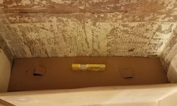
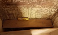
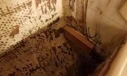
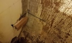
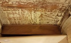
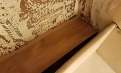
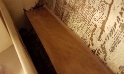
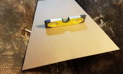
Using my plywood mockup, I placed the tank in the desired location outboard of the head and made some marks on the two adjoining bulkheads where the ends of the tank fell, which would give me a starting reference point for the new platform’s location. From there, I created a cardboard template of the space, first with a rough piece on which I could scribe, then a more accurate template based on the first go-round. Once I was satisfied with the template, I transferred it to 12mm plywood and cut out the platform itself, leaving 1-1/2″ extra width inboard of the tank width itself to allow for support cleats and minor adjustments. This left some open space within the locker that would be required for hose access and the like.
After marking the ends of the platform on the bulkheads (with the platform level in both directions), I removed it and used a hole saw to cut a large hole through the forward bulkhead and into the space beneath the starboard settees, where the overboard pumpout through hull would eventually be located. To comply with discharge requirements, all waste would be routed into the holding tank first, but from there would be the option of evacuating the tank to a shoreside facility (through a deck fitting) or overboard via a hand pump when the boat was in waters legal for such behavior.
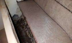
After cleaning up the space, I installed a pair of hardwood cleats for the ends of the platform, securing them to my marks with epoxy and screws, before installing the platform on the cleats and against the hull with more epoxy, and a pair of screws into the cleats just to hold it. I coated both sides and all edges of the platform with epoxy before installation, and smoothed in a nice fillet along the hull and at any gaps at the ends.
To complete the installation, I installed two layers of heavy fiberglass over the platform and up on to the hull.
Now that I was on a roll, and anxious to finish up structural and epoxy work in the boat’s various compartments, I decided to work next on the new support platform for the boat’s electric propulsion motor (and please forgive me if by habit I lapse into calling anything here an “engine”). With the basics of the system chosen by the owner now determined, I was ready to figure out the motor placement and also where the large battery bank would be stored.
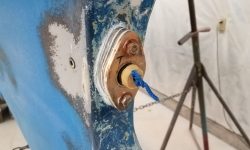
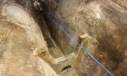
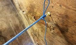
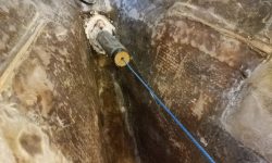
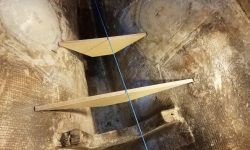
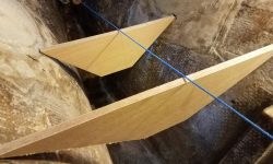
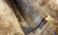
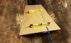
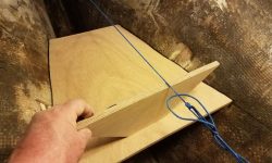
To begin, I set up a string through the shaft log so I could determine the shaft position and angle, which, as always, was the key reference point for such an installation.
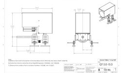
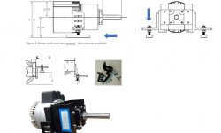
A great benefit to electric propulsion motors from my standpoint is that, because the motor is compact and lacks all the protrusions and low-hanging transmissions and oil pans found in diesel engines, it can be mounted on a simple flat platform, and in this particular boat such a basic platform worked well with the given space in the engine room. Using the reference drawing of the chosen electric motor, and the measurements contained therein, I chose as a starting point 5″ below the shaft centerline, which was well within the requirements of the motor installation itself and would also give ample room for minor adjustments in height later. If, during final installation, I found it beneficial for whatever reason to add height to the platform, it would be straightforward to do easily and accurately, but the mounting system with this motor provided substantial adjustment capability for myriad situations.
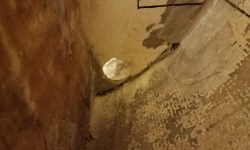
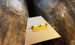
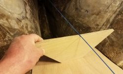
To transfer a starting baseline down from the shaft centerline, I cut a pair of plywood pieces to 5″ in height, and wide enough (and with sharp angled ends) to extend from hull to hull in a couple different positions along the shaft line. With the angled ends resting on the hull, I could level the plywood and then use a small straightedge held tight to the bottom edge to transfer a mark to the hull at the new, lower height. I drew a line between the two points on each side with a flexible metal ruler. Positionwise, I planned to begin the platform just at the forward edge of the old scupper locations (which would soon have new seacocks installed), and extending 18″ forward from there, which happened to be the overall length of the electric motor and housing, but mainly this platform size would give me final mounting options later, as the full length wasn’t required for the mounts themselves.
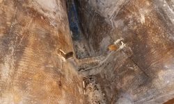
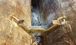
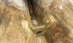
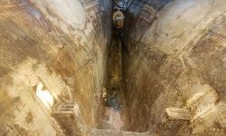
The line ran into the V-shaped small bulkhead that was leftover from the original engine installation, so as best as I could I transferred the new line around the support and cut off the top with a saw, which I found to be difficult in the small space, leading to bent blades and, on the starboard side, an inaccurate cut–but for the moment it was good enough. Now I could continue the line forward as far as needed, after which I measured for and cut a basic plywood template to fit.
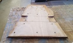
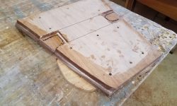
My first cut on the old support had allowed the cardboard to pass by, but I wanted the final platform to rest just on top of and wrap around the existing support so as to incorporate it into the new structure. I planned to build the platform from a laminate of 2 thicknesses of 12mm plywood, so I made new marks on the top of the support using a scrap of the plywood as a guide, then cut to the new marks with a grinder and cutoff wheel, which was accurate in the confining space but created lots of wood smoke from the support’s plywood core.
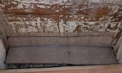
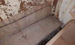
Now I transferred the template shape to one sheet of 12mm plywood, and after some minor adjustments fit the piece in place, level from side to side, in the proper longitudinal position, and 5″ below the shaft centerline.
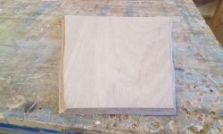
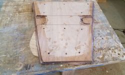
My last task before knocking off for the day was to use the first piece of plywood to transfer the shape to a second layer, which I glued to the first layer with epoxy adhesive after cutting out little notches in the bottom layer to fit around the engine room bilge support. I used temporary screws to clamp the two pieces together while the epoxy cured overnight.
Total time billed on this job today: 8.25 hours
0600 Weather observation: 8°, clear. Forecast for the day: Sunny, 24°


