

December 4, 2019
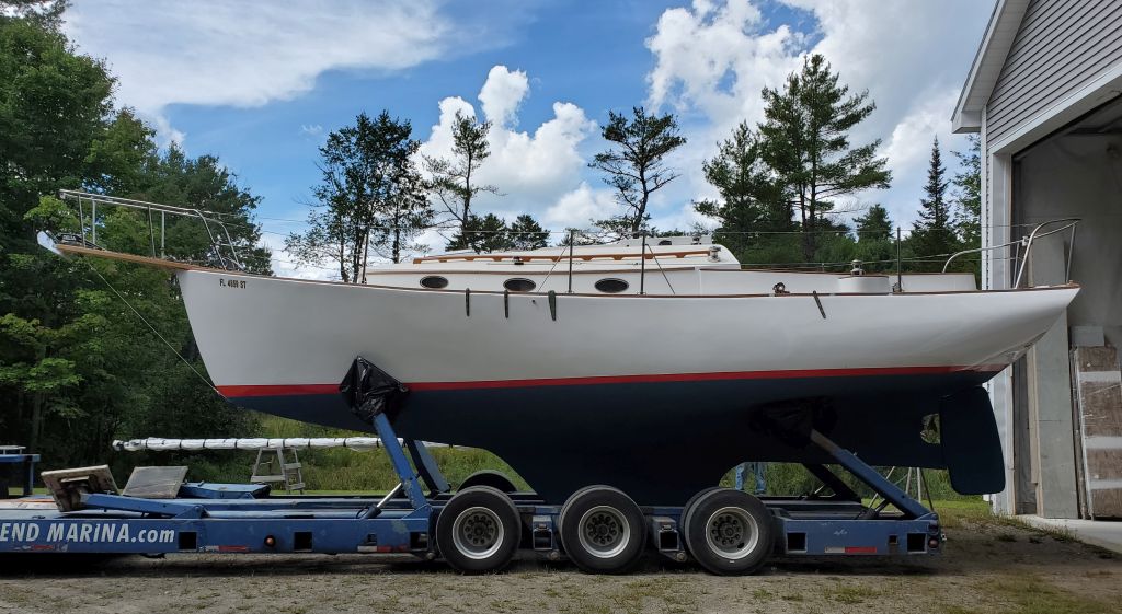
Scupper 195
Wednesday
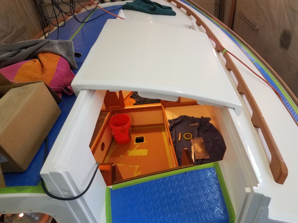
Now that the interior companionway hatch paint was complete, I was ready to move on with its final installation. First, however, I wanted to install a solar vent that the owner requested. To my dismay, however, when I opened the package I found the vent was absolutely massive, which was one thing, but even worse, it was incredibly tall/deep, and I knew at a glance that the housing was far too deep to work in the companionway, which was only roughly 3/4″ thick. It had been quite a while since I’d put one of these in, and apparently these vents have changed significantly from what I recalled.
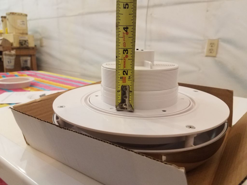
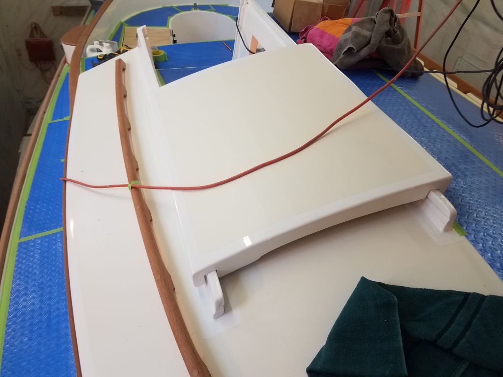
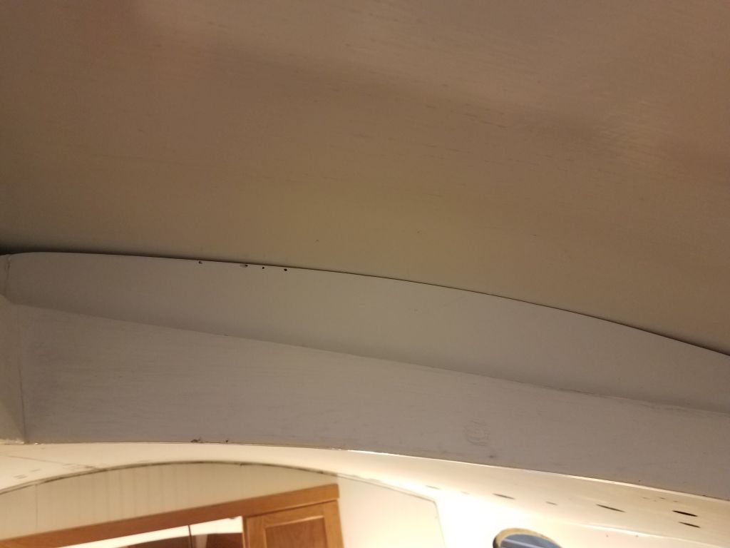
I didn’t think there was much clearance below the hatch where it passed over its rails on the boat, but to be sure I brought the hatch up on deck and placed it in position, and checked the clearance beneath: essentially none. This meant that any vent in the hatch would require a flush fit from beneath. To an extent, I could install a minor riser beneath the vent to reduce its depth a little, but not as much as would be required by the huge vent I’d ordered. I packaged up the large vent for return, and sourced and ordered another, smaller version that I thought had a better chance of working.
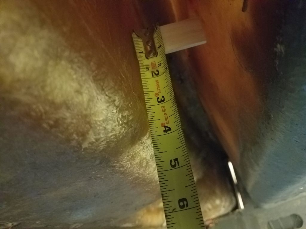
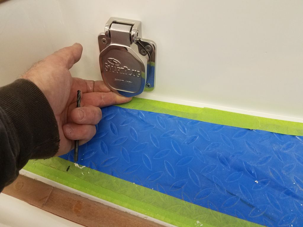
Putting that temporary failure behind me, I moved on to the AC shore power inlet. The owner had got in touch to let me know that he thought the inlet should be on the port side, which matched his slip configuration better than the starboard, so to confirm the possibility I used my little wooden stick to check the clearance inside the port coaming just aft of the winch island, where the plug would be out of the way of sailing gear. With the top of the stick wedged in place within the coaming, I measured beneath it (about 3.5″ to where I estimated the top of the deck to be), which was enough space to install the receptacle there.

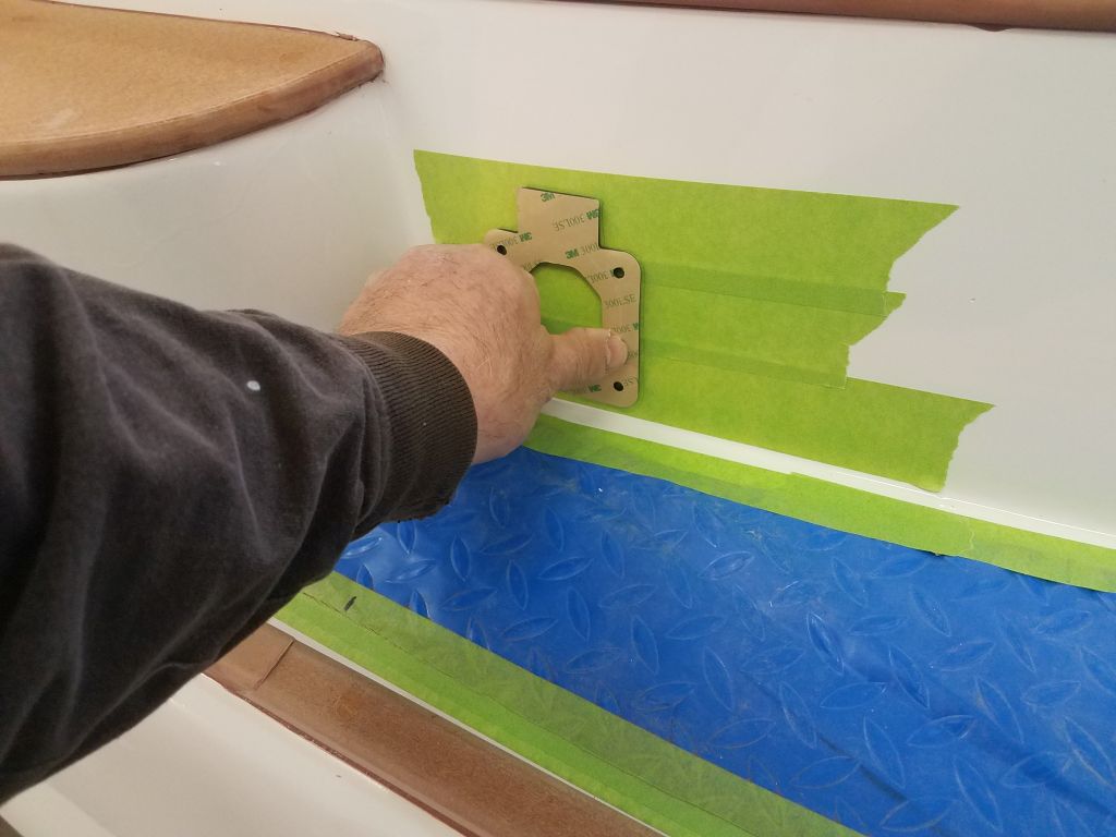
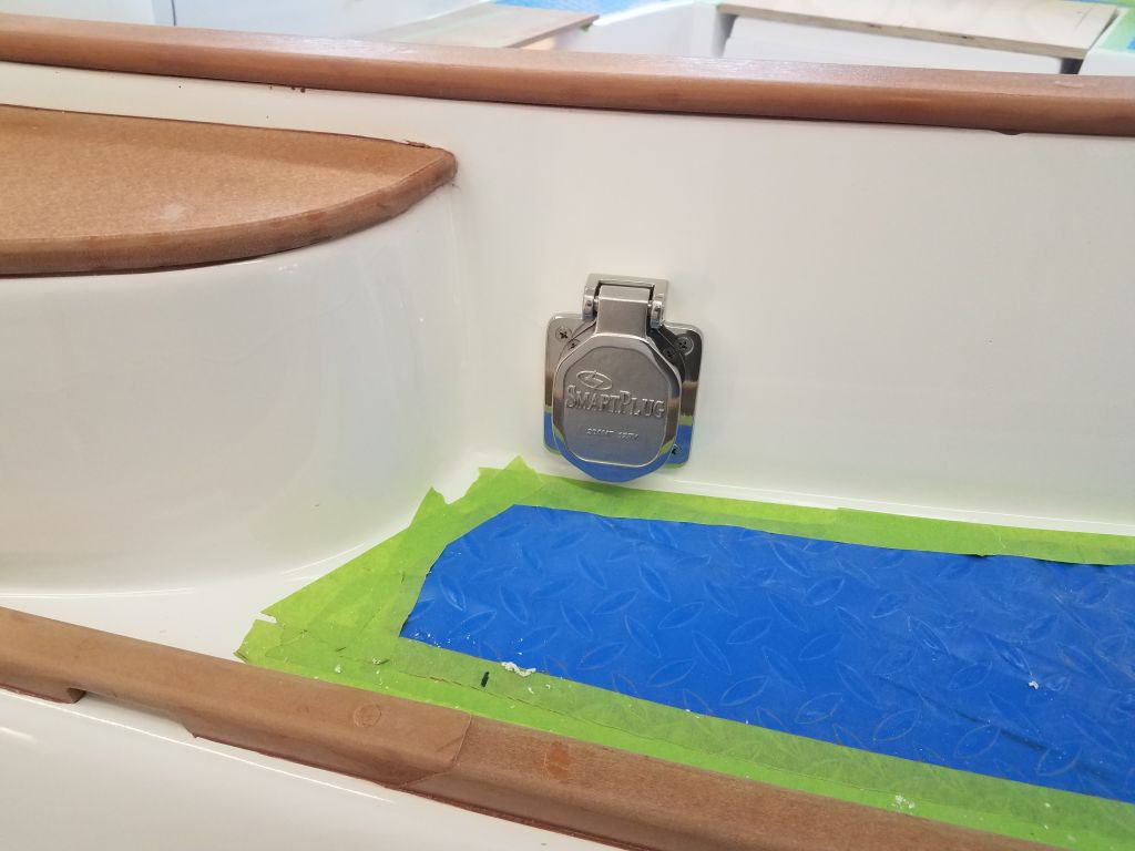
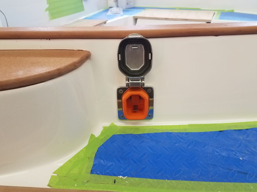
With the position confirmed, there was no time like the present to do the installation, so using the backing gasket as a guide, and confirming the cutout’s location against the required maximum height from within, I cut a hole for the receptacle and dry fit it with some screws. The housing fit inside the coaming with a little room to spare. Of course I’d have to do the wiring from outside before installing the receptacle, but this posed not problem. The receptacle ended up fairly close to deck level by necessity, but this still allowed easy finger access to lift the cover, and as an added yet unplanned benefit, the cover, when opened completely, remained just below coaming height.


I was prepared to go ahead and pre-install the wiring and complete the receptacle installation, but after giving it some thought I realized that I should use 10/3 wiring from the plug to the panel, partly because it was some distance to the panel, wiring-wise, and partly because of the anticipated loads the boat’s pair of battery chargers (one for the 48-volt engine bank, one for the separate 12-volt house bank). I had 12 gauge wire in stock, but had to order the 10 gauge since I rarely use that size.
With another job temporarily stymied by the impossible desire to have everything I could possibly need for any situation on hand the instant I needed it, I moved on to the electric motor, looking to wrap up its installation as much as possible. By design, I chose not to have the new 6-volt batteries for the engine and house banks on hand till later in the project, when the wiring and charging system was complete and I could maintain the batteries, so I knew I couldn’t completely wrap up the battery cabling, but I could take care of the basics now, starting with the raw runs of positive and negative cabling from the engine to the eventual battery bank.
To begin, I used one of the battery boxes I had on hand to make some temporary marks in the engine room, largely for overall height so I’d not install any cabling below that level, but also to mark out a cable run in the center of the forward battery shelf, where I planned to run the cables between the two boxes that would sit on the shelf. There would be four battery boxes in the engine room, each holding a par of 6-volt batteries: two on the forward shelf, and one each on the shelves flanking the engine room on each side.
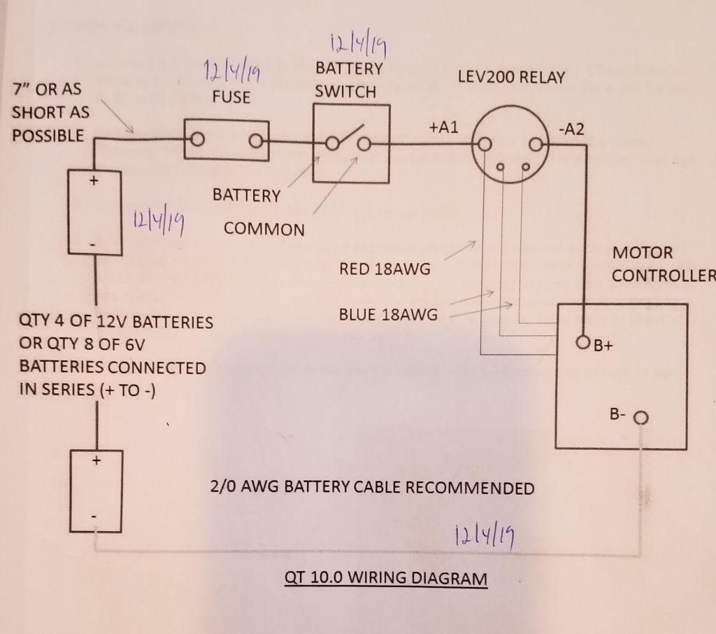
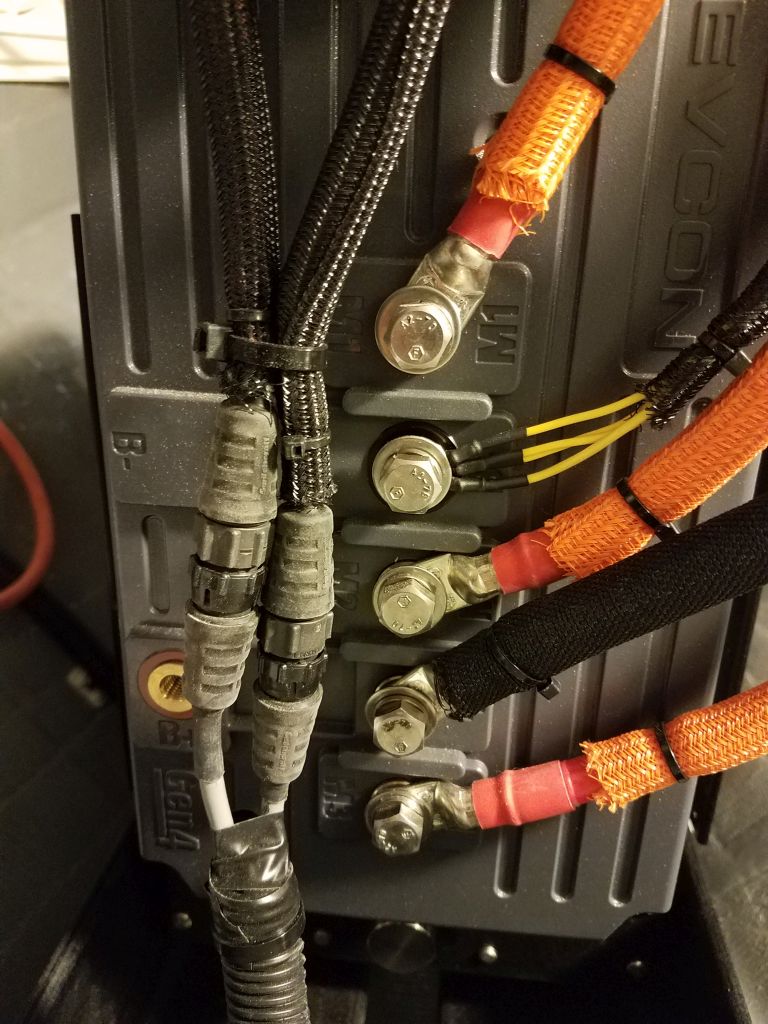
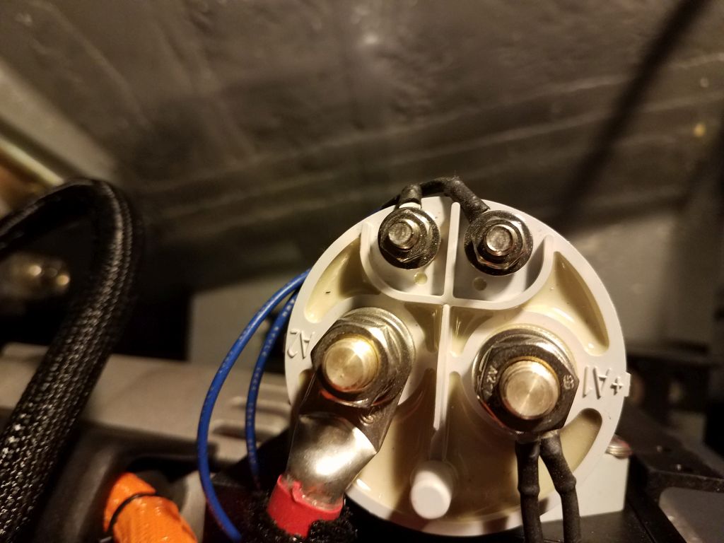
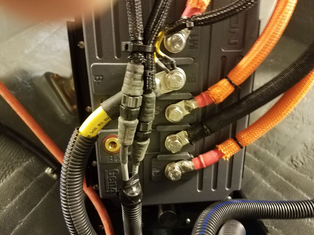
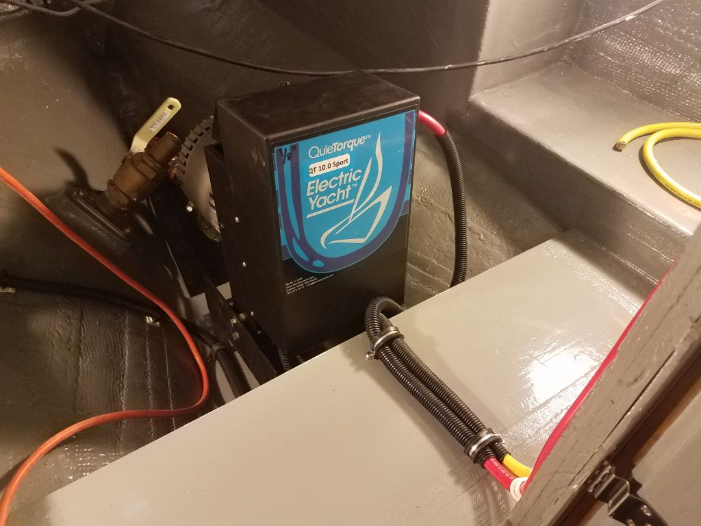
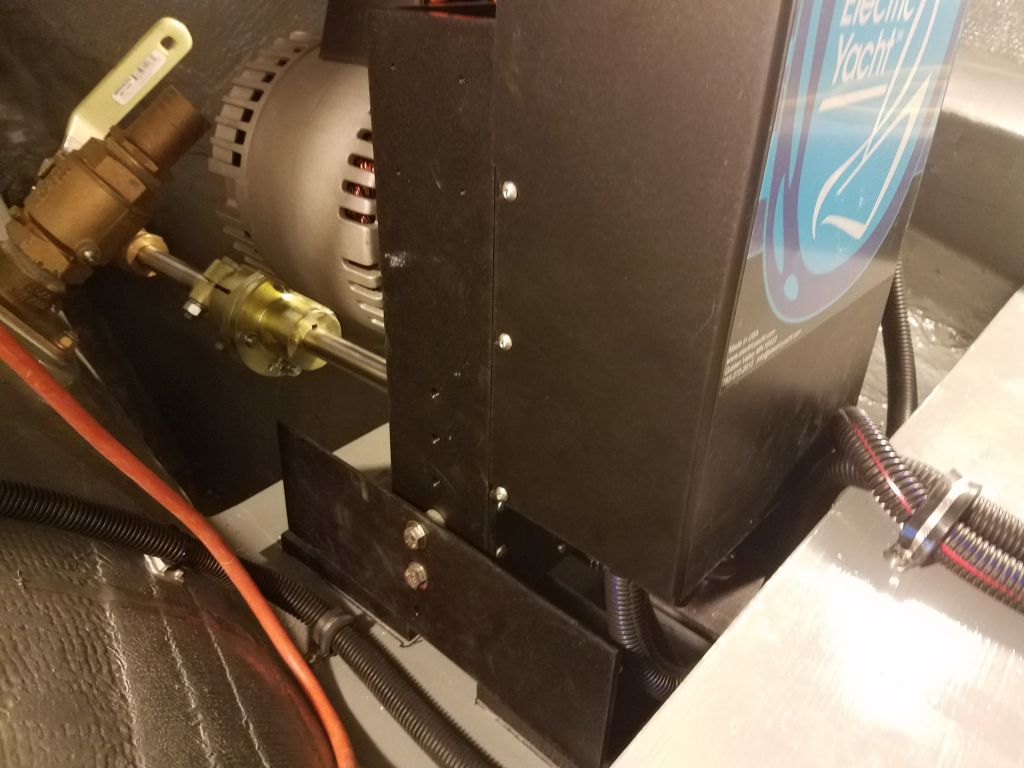
The engine wiring plan, shown below, was straightforward overall, and all the engine-based cabling and wiring (to and from the motor and motor controller box) was pre-installed at the factory, so my job now boiled down to installing positive and negative cables to the required terminals on the motor itself: that is, terminal “A1+” on the side-mounted solenoid (positive) and the B- terminal on the motor controller (negative).
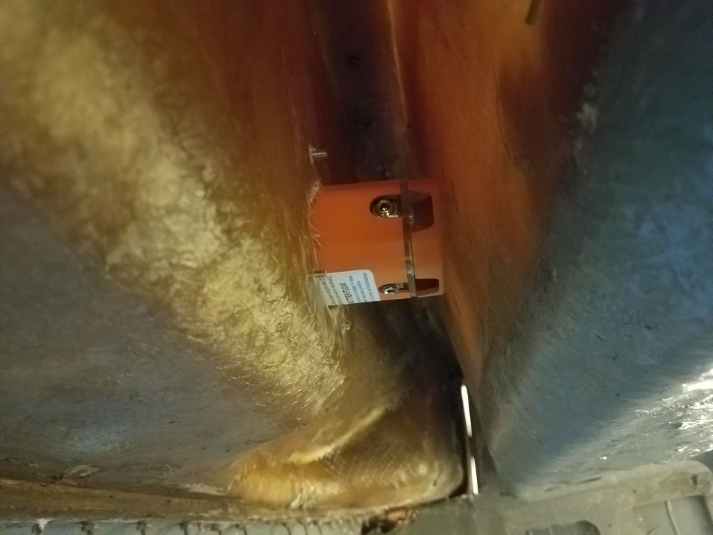
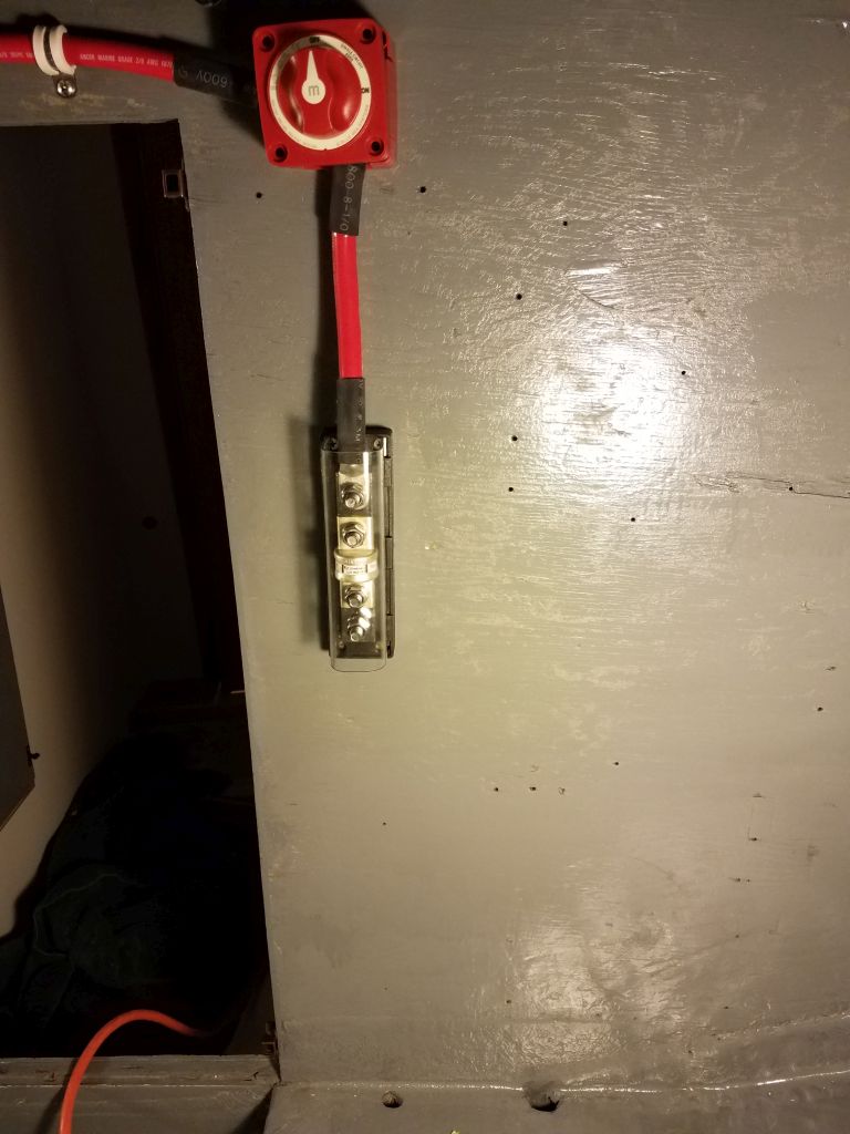
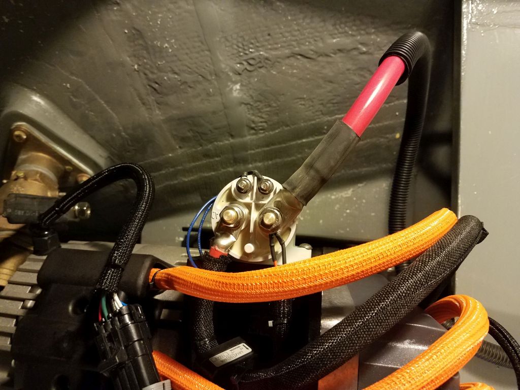
For no particular reason other than best access, I decided the positive side of the bank would start on the starboard side, where the access door from the head was located, and to begin I installed the 250-amp fuse holder a few inches above the battery box, staying close enough that the final cable length between the battery terminal and the fuse would be as minimal as possible. I’d wait to install that short length of cable till I had the batteries on hand.

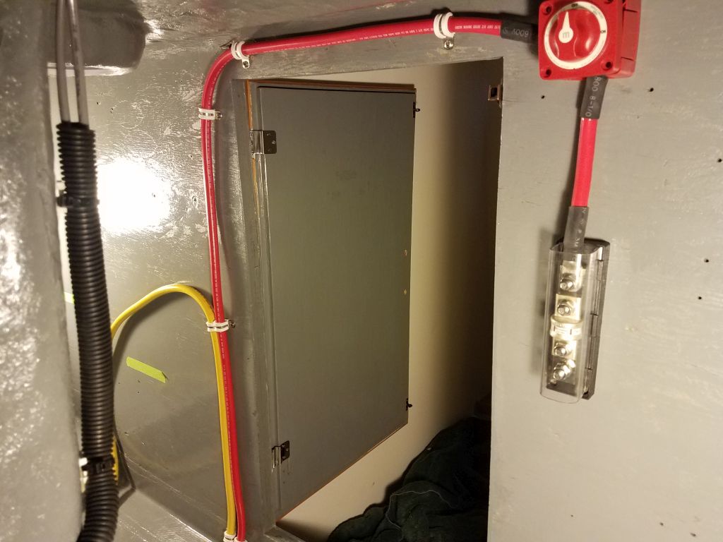
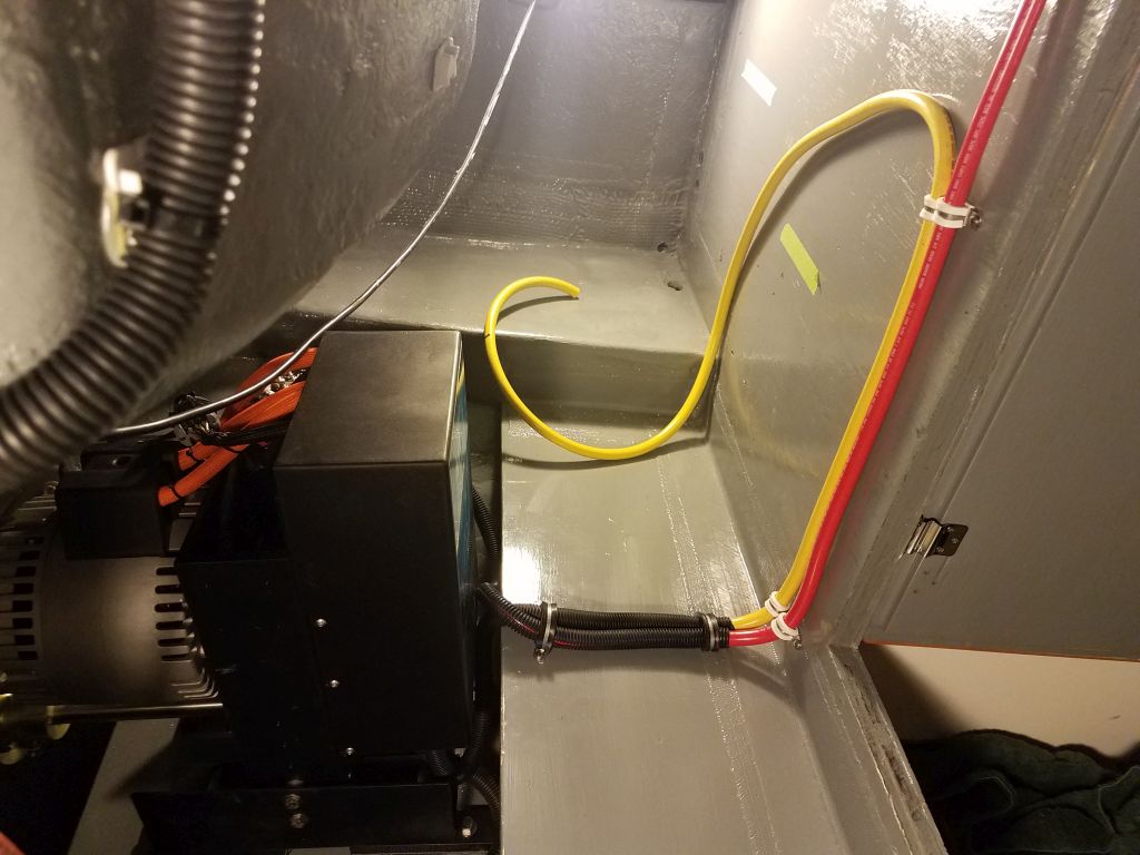
Next in the circuit was an on-off switch, a basic battery switch, which I installed a bit above the fuse and easily accessible from the engine room access door, connecting it to the fuse with a short length of 2/0 cable. Then, I led another length of the cable from the switch, above the doorway, and down the bulkhead and across the battery shelf through the open area in the center that I’d laid out. (Note that the photos might jump a bit ahead of the text from here on since, because of poor access, I only photographed the setup when I’d completed the day’s wiring.)

I protected the cable with some flexible conduit where it crossed the battery shelf and engine space, and connected the other end to the proper terminal on the solenoid.
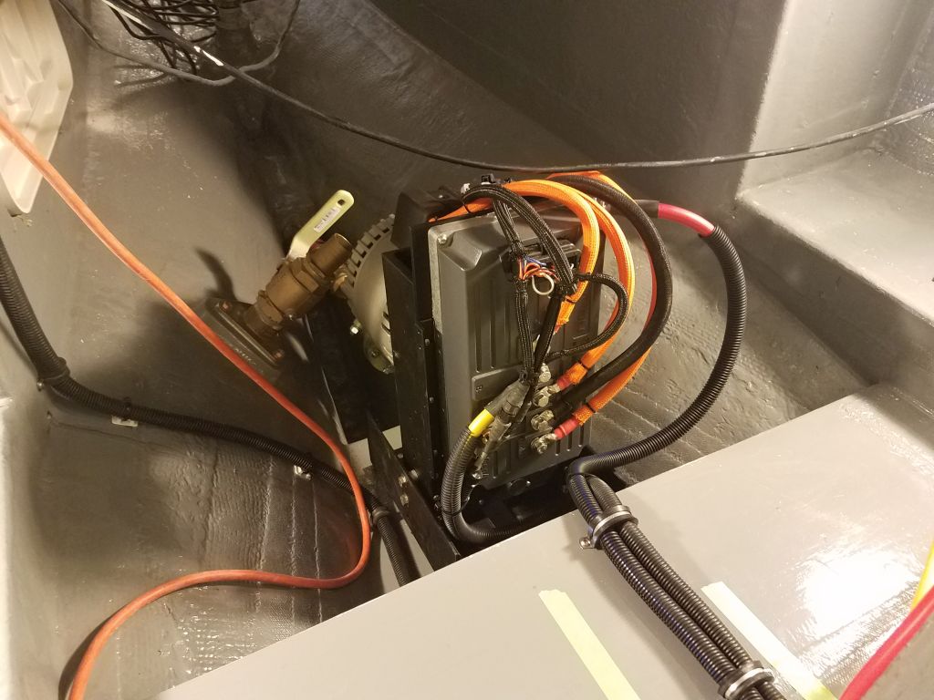
The negative battery cable needed to lead from the B- terminal on the controller box over to the port side of the eventual battery bank, so leaving ample cable for later termination, I led the cable from the engine and across the battery shelf, secured in closely with its positive compatriot. I ran out of line clamps of the right size, so for now I left most of the yellow cable unsecured, but I’d take care of that once my replacement clamps arrived. The 2/0 cable is heavy and stiff to work with, and I had to leave clearance for the sheet metal control box cover as I planned these cable runs. Upon review, I realized I could redirect slightly the red cable run from the battery shelf to the solenoid connection, and made plans to do so.
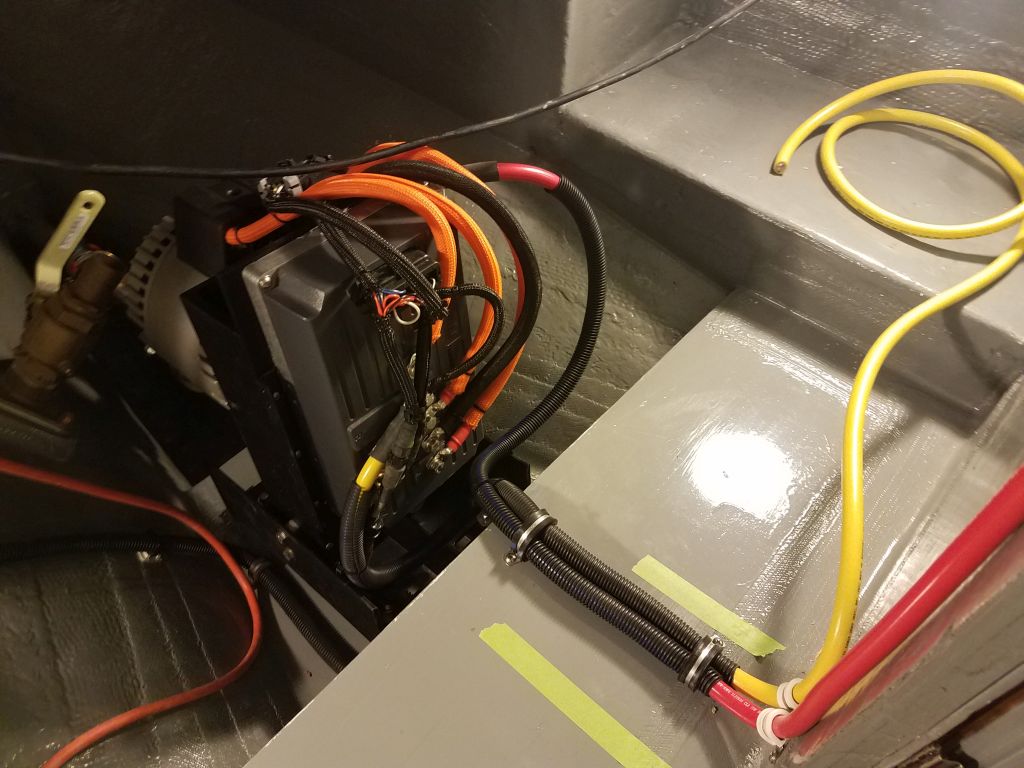

With the bulk connections complete, and after double-checking the connections and tightening the bolts securely, I decided to install the cover to protect the wiring and because it was unlikely I’d need to get back in there.

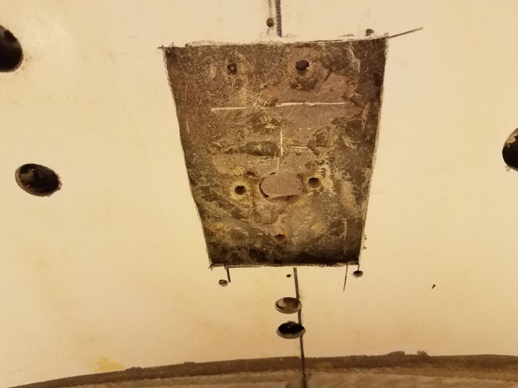
Since the designers saw fit to place the main bulkhead only 12″ forward of the mast step, the mast step required a compression post beneath to transfer its loads to the keel below. Looking to complete and install this post in the near future (and also to finalize how it was going to work with the new cosmetic plywood overhead panels), and also as I prepared to install the mast step on deck at the earliest convenience, I turned to the underside of the deck now to figure out how to proceed. In the original fiberglass liner/overhead, holes had allowed access to the nuts and washers that had originally secured the mast step, but now I thought it would be easier if I simply cut out a portion of the old liner to open up access to the whole space.
Of course one thing led to another, and my initial cuts showed that there was a mass of (what turned out to be) unthickened polyester resin filling the space immediately beneath the mast step, with little hollows where the mast step bolts had been. This had been to create a solid transfer between the deck and the liner, and thus with the original compression post, and this had worked fine for the boat’s life up till now.
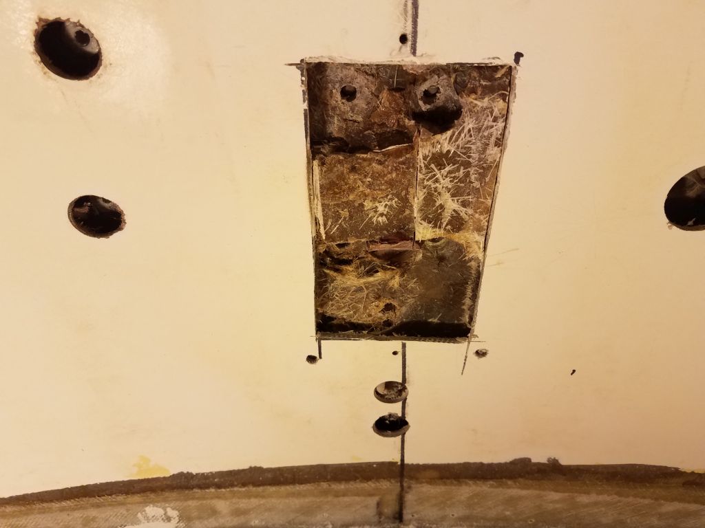
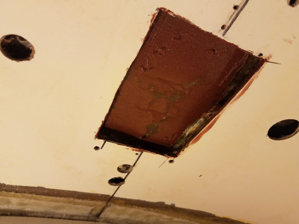
Since I had the area open now, I decided to remove the old resin and start fresh with a solid laminate of fiberglass instead; because the whole area would be covered with my already-completed plywood panels, the appearance of this area didn’t matter. So at some length I cut, chipped, and sanded away the old material till I reached the bottom of the deck laminate. This left a somewhat uneven surface, so once I’d cleaned up and just before quitting time, I applied a skim coat of thickened epoxy that would give me a better base for the solid fiberglass once it cured.


Total time billed on this job today: 8 hours
0600 Weather Observation: 12°, clear, 8″ snow from yesterday. Forecast for the day: Mostly sunny, 35°