

April 2, 2019
Scupper 114
Tuesday
Normally, I’d leave interior varnish work till the end of the day, so I could work in and around and wherever, but since I wanted to be sure to get the base coats underway, and with the whole boat prepared for the purpose before I had to leave unexpectedly the day before, I chose to do the varnish work first thing, to ensure its completion, all the more so because I wasn’t sure how long it would take.
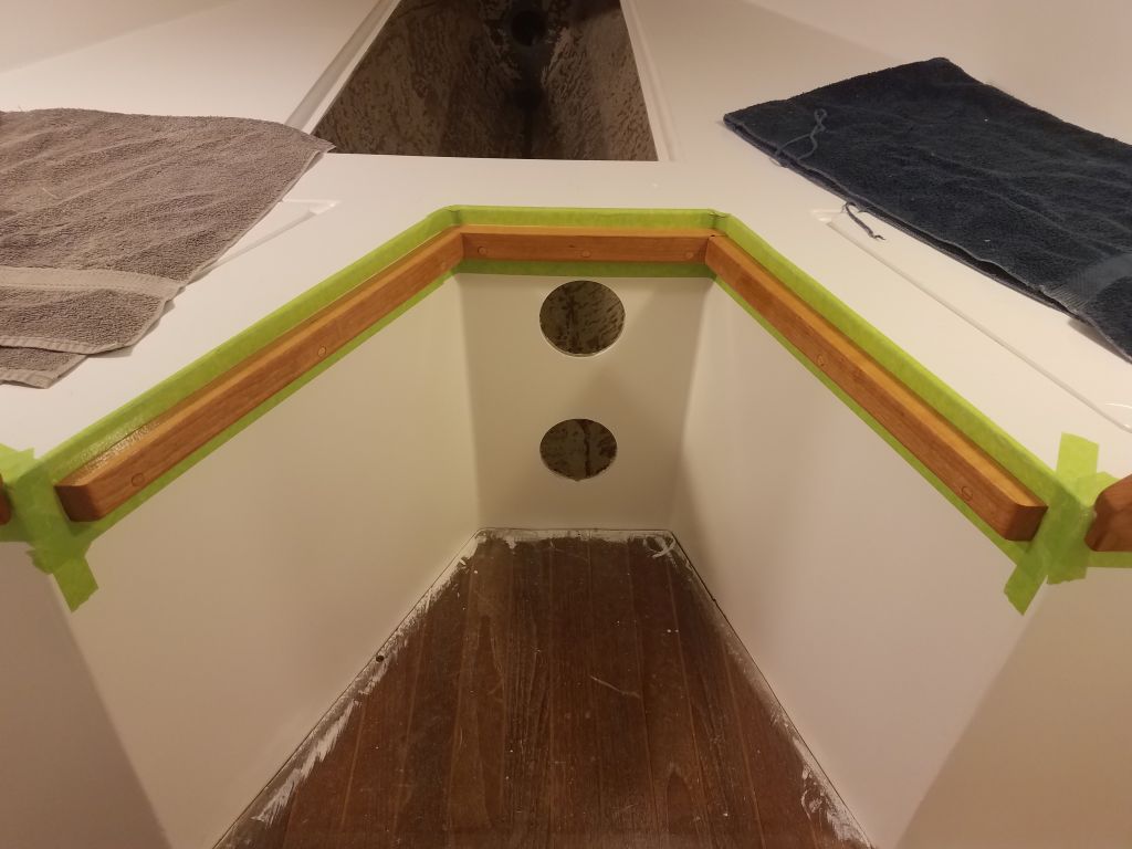
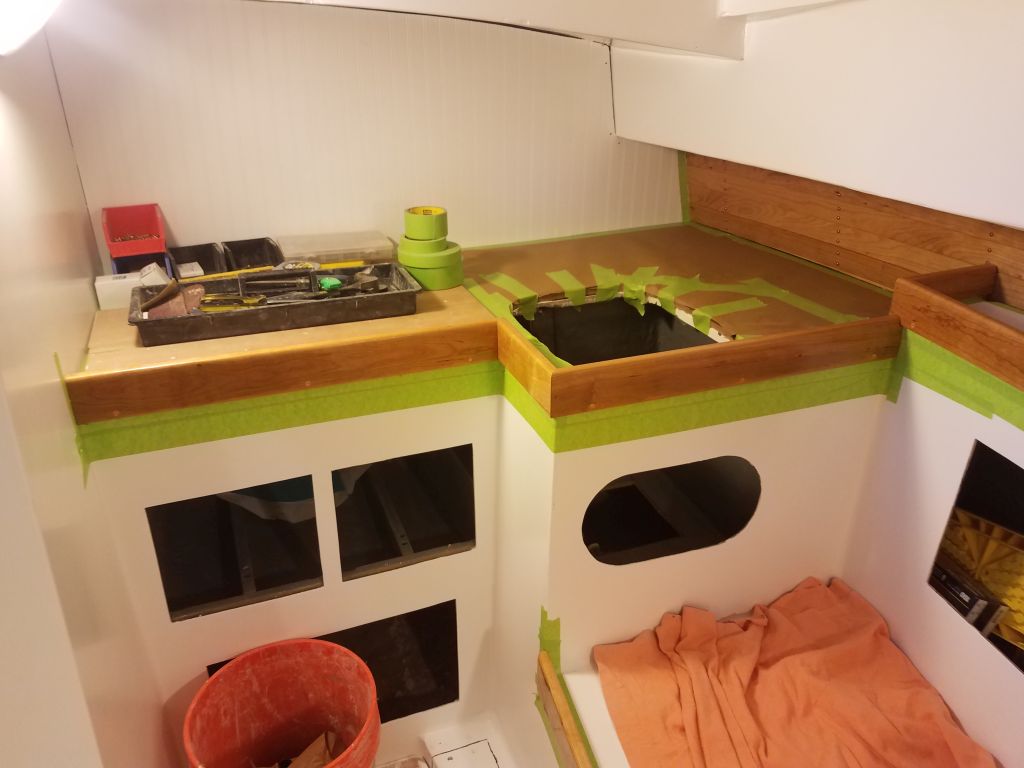
I began with the small trim pieces, electrical locker panel fronts, and the forward hatch frame, all of which had been underway for some time and were using more or less full-strength varnish at this point. I say more or less because I find that in ambient shop temperatures (usually in the mid-50s), it’s beneficial to add a bit of reducer for flow purposes.
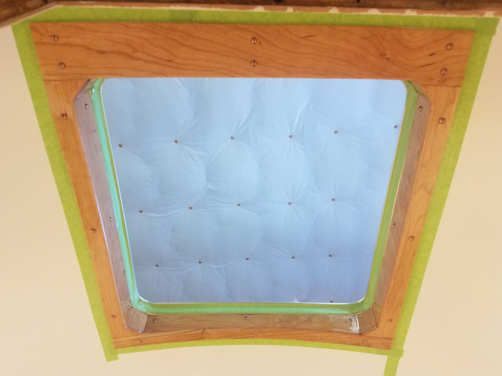
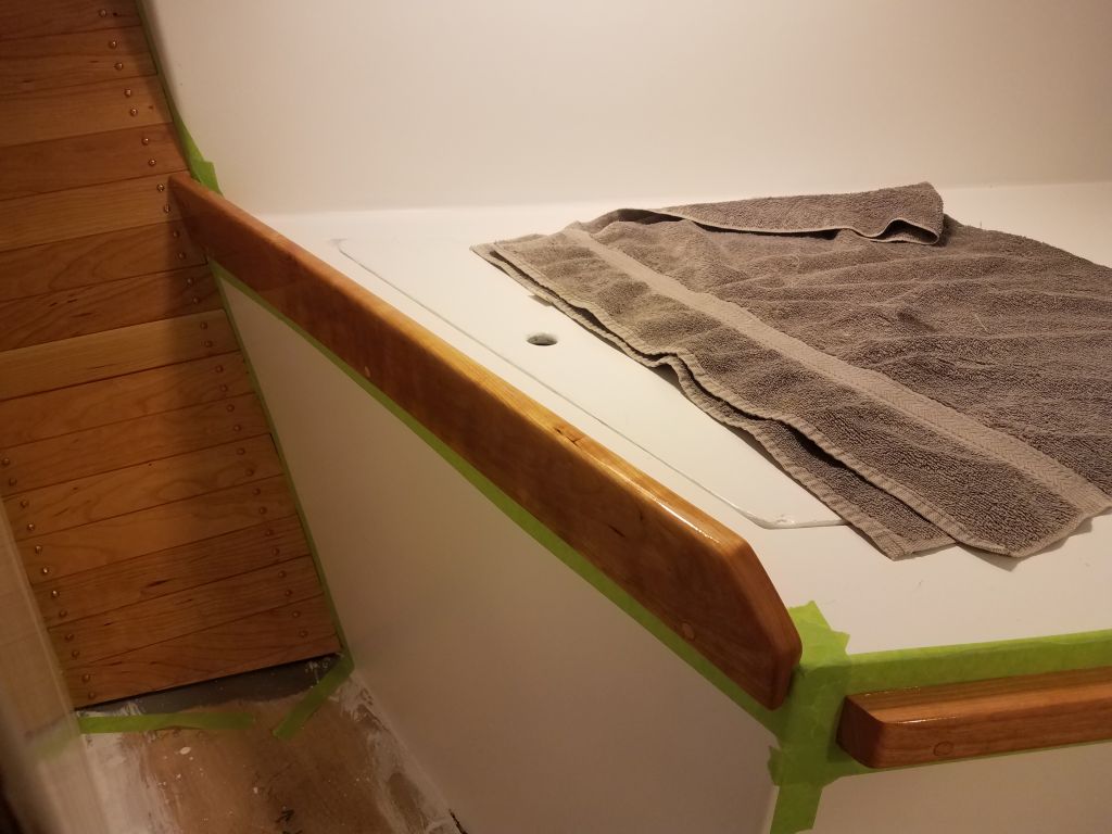
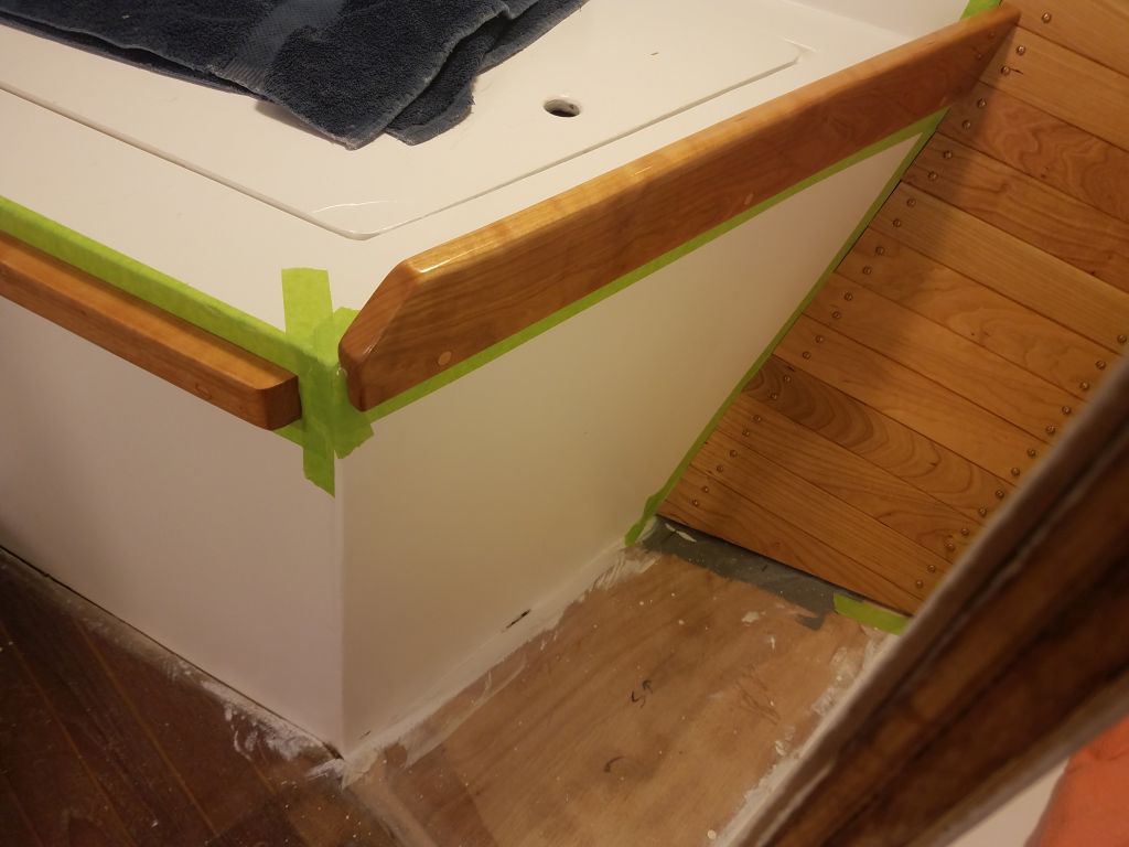
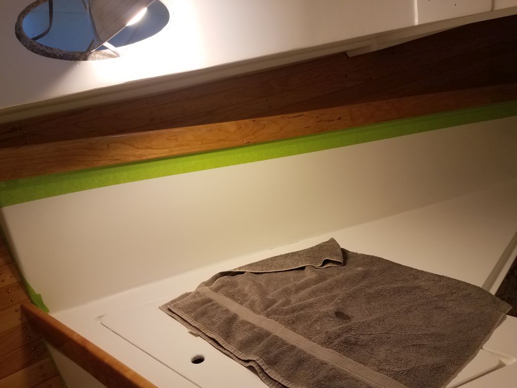
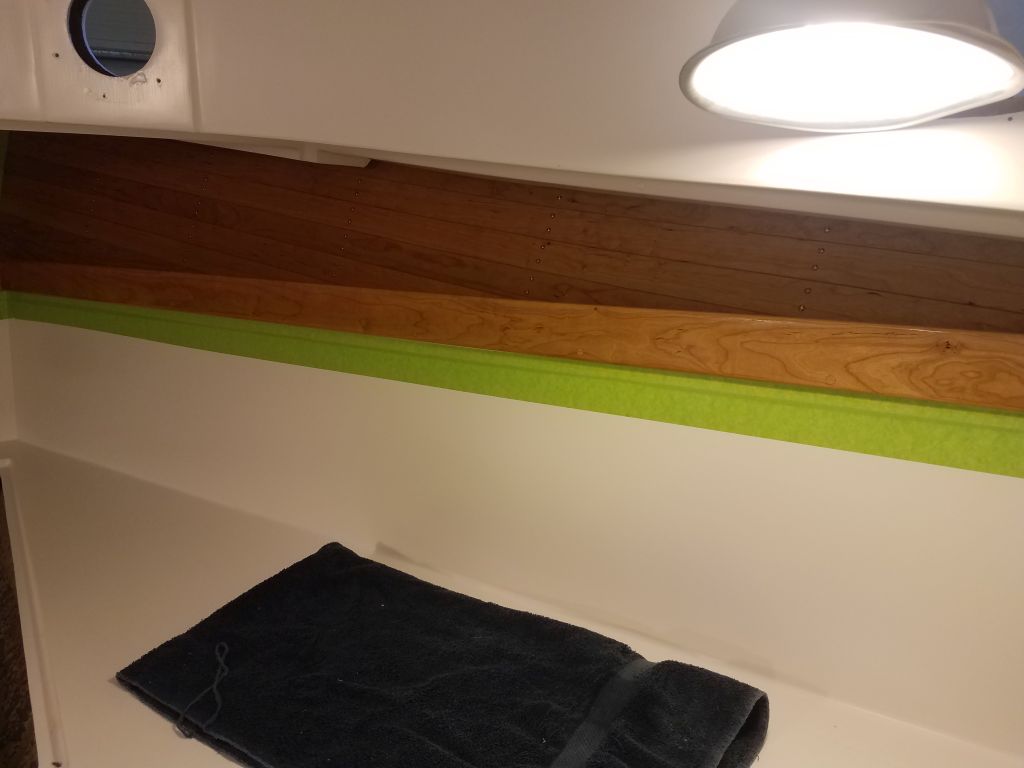
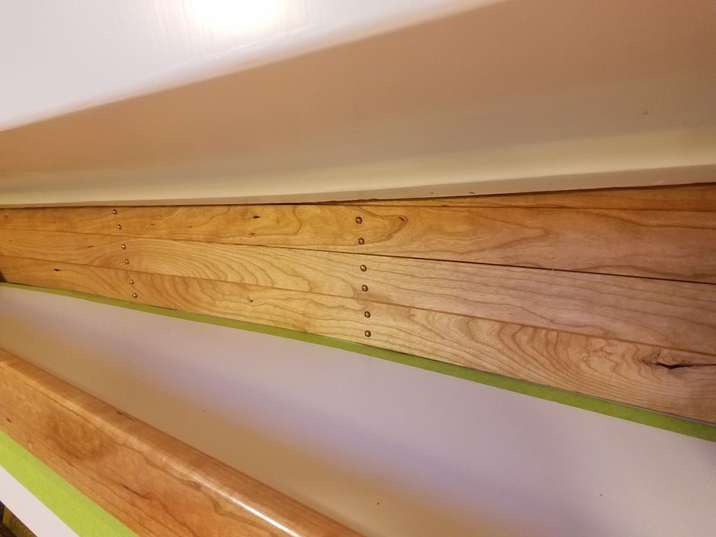
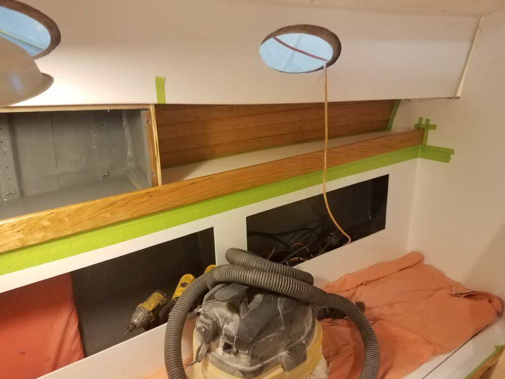
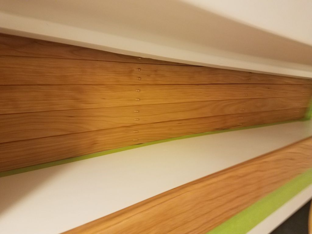
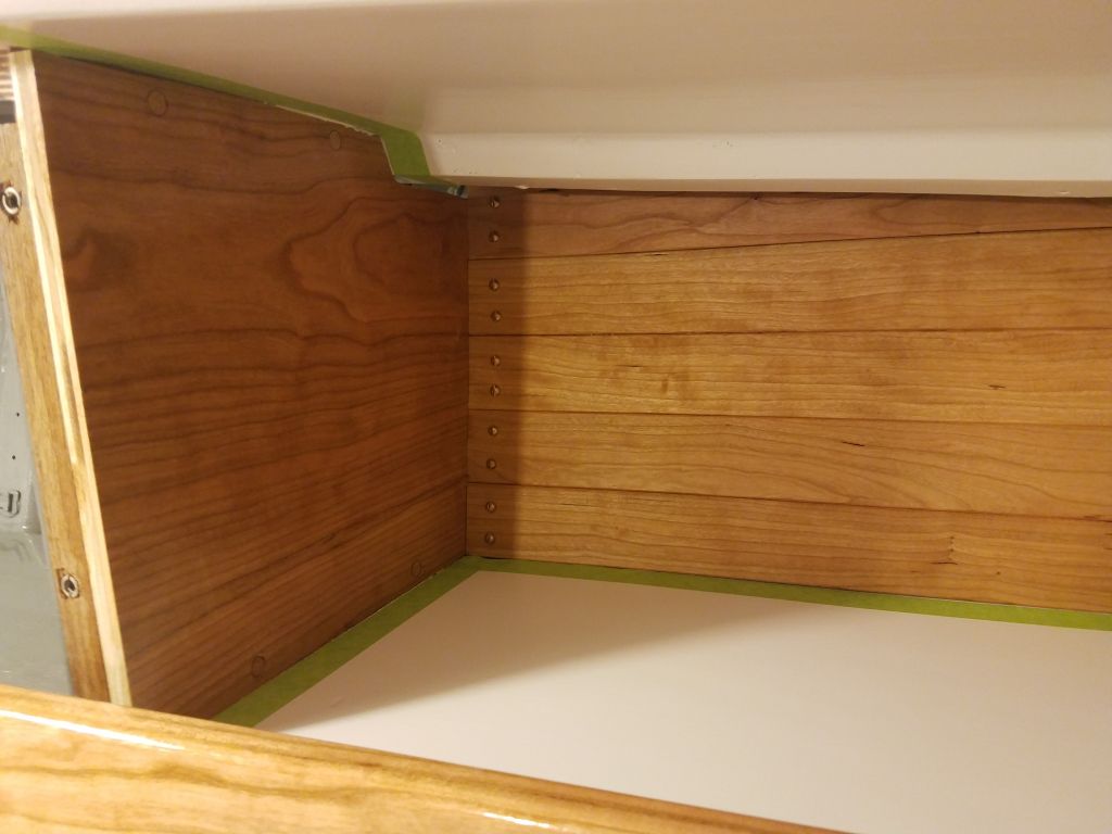
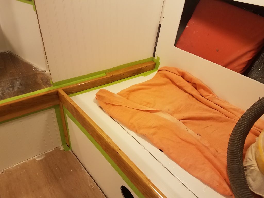
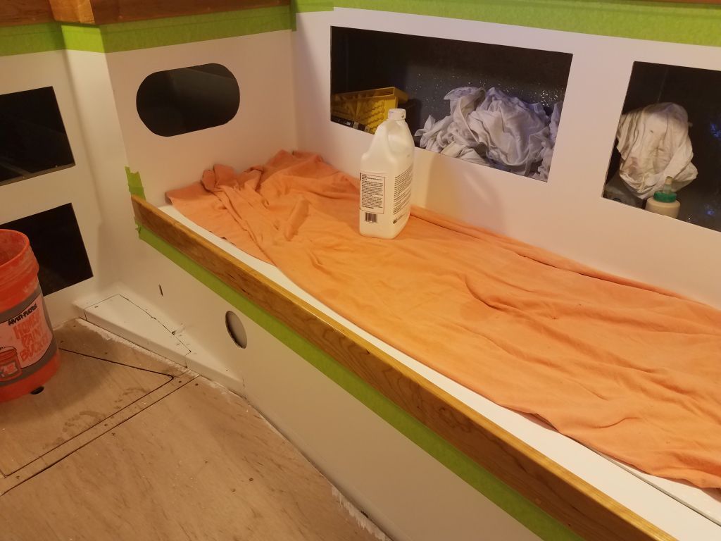
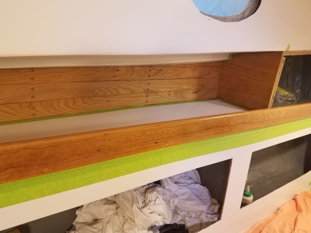
I like to use a wiping tung oil varnish finish for the ceilings, as it’s quick and neat to apply over the large areas with many fasteners, and cures to a satin finish virtually identical to that which I’d ultimately achieve on the other trim with the rubbed-effect satin product I’d finish with. On the ceilings, I began with the first coat of the wiping varnish on the ceilings before moving on and applying the first coat of varnish to all the installed trim in the boat. This was really the second coat on the trim, since all of it had already received a sealer coat before installation, but with the new bungs and light sanding, it effectively reverted to coat one for my purposes now.
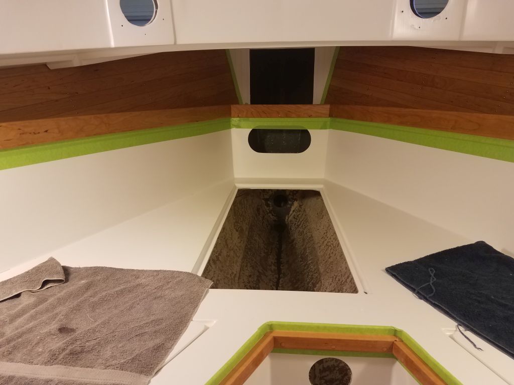

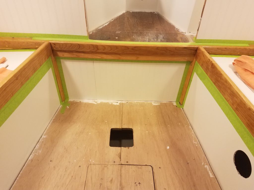
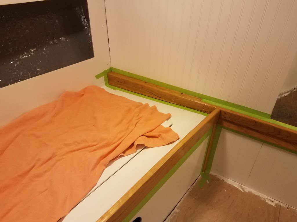
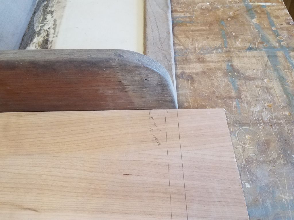
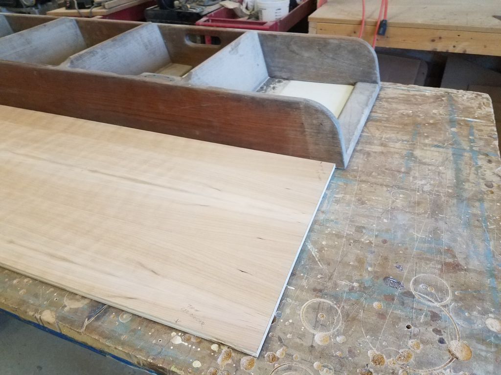
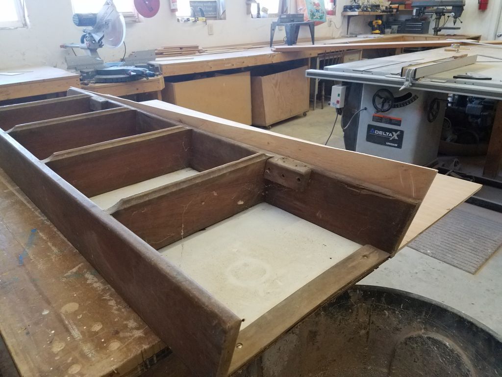
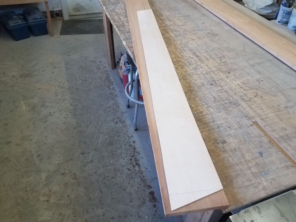
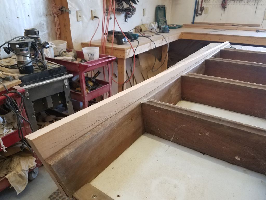
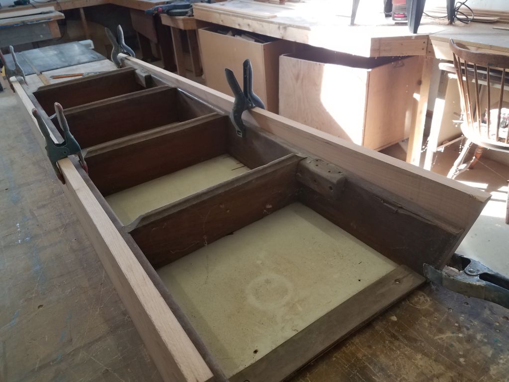
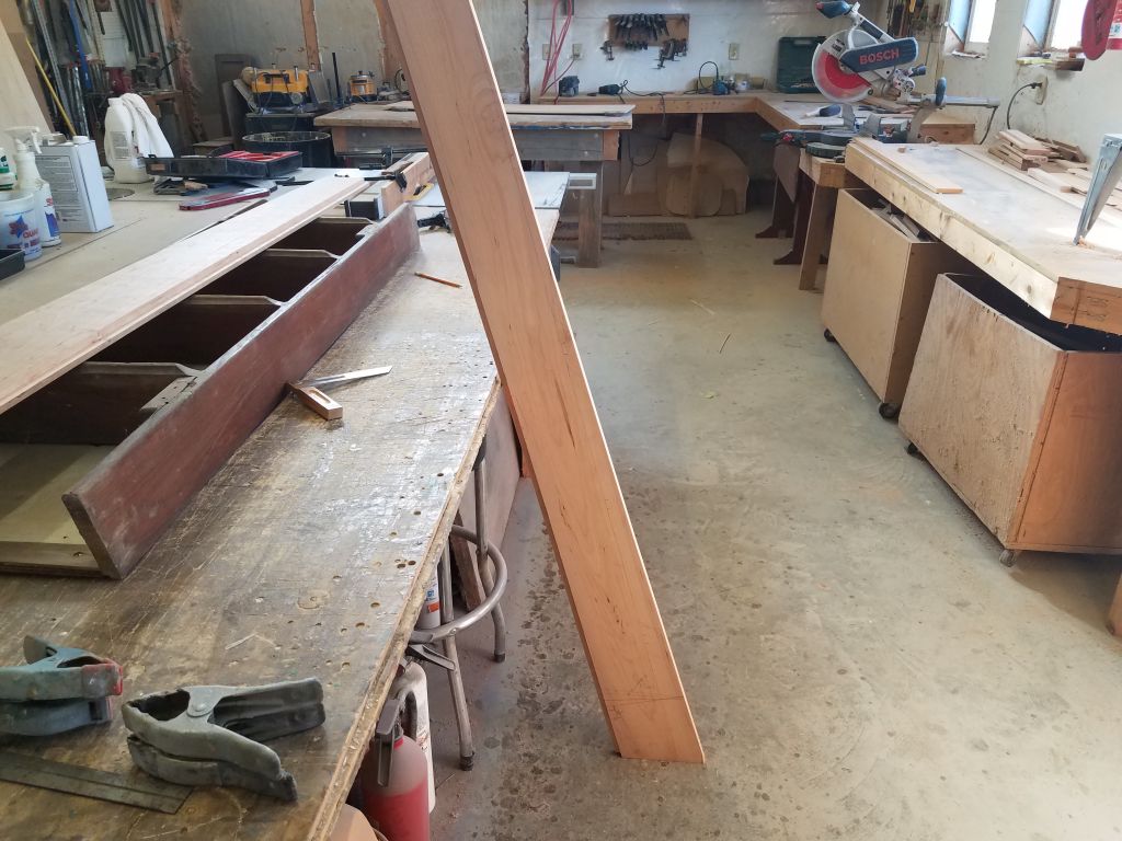
Knowing that the fresh varnish would ban me from the cabin for the rest of the day, before I started early in the morning I test-fit the plywood panel I’d previously cut for the companionway ladder/doorway assembly, as I planned to work on this down in the shop for the remainder of the day. I’d sized the panel according to the original ladder assembly, but left it intentionally over-long for final trimming, so now, with the panel in place and set up at the proper angle, I made a few reference marks where the panel passed key parts of the boat since at the moment I wasn’t sure how the original ladder had worked (later I reviewed the photos of the original interior to help work this out).
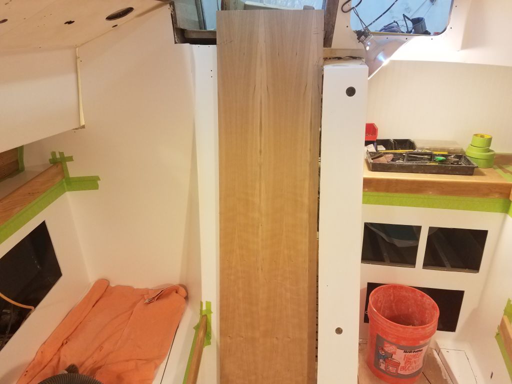
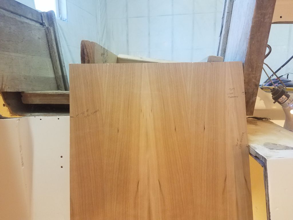
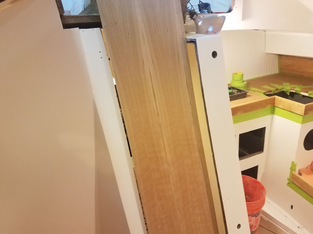
The original ladder assembly had extended up even with the threshold of the companionway, which was one of the reference points I’d marked on my new panel, so with this and the original ladder as guides, I eventually chose to trim the top of the panel straight and square about 3/4″ lower than that, leaving room to add solid trim at the top that would incorporate the ladder angle and cover the edge grain of the plywood.
During earlier discussions, the owner had requested a few small, but significant, changes to the ladder, including increasing the angle if possible, as well as providing back-angled treads for increased security. Because the angle of the basic assembly was required to match that of the adjacent structures in the boat, which, like the original ladder, were sloped at 15°, the only way to practically change the ladder’s final angle was to add in the angle on the side rails of the ladder itself, increasing its width towards the bottom. We were shooting for an increase to 20°, which had the effect of actually lessening the steepness of the ladder and would make the ascent and especially descent easier going forward. This was a reasonable compromise between the fixed requirements of the existing structures and the desired ease of ingress and egress, while avoiding the ladder taking up too much space in the process.
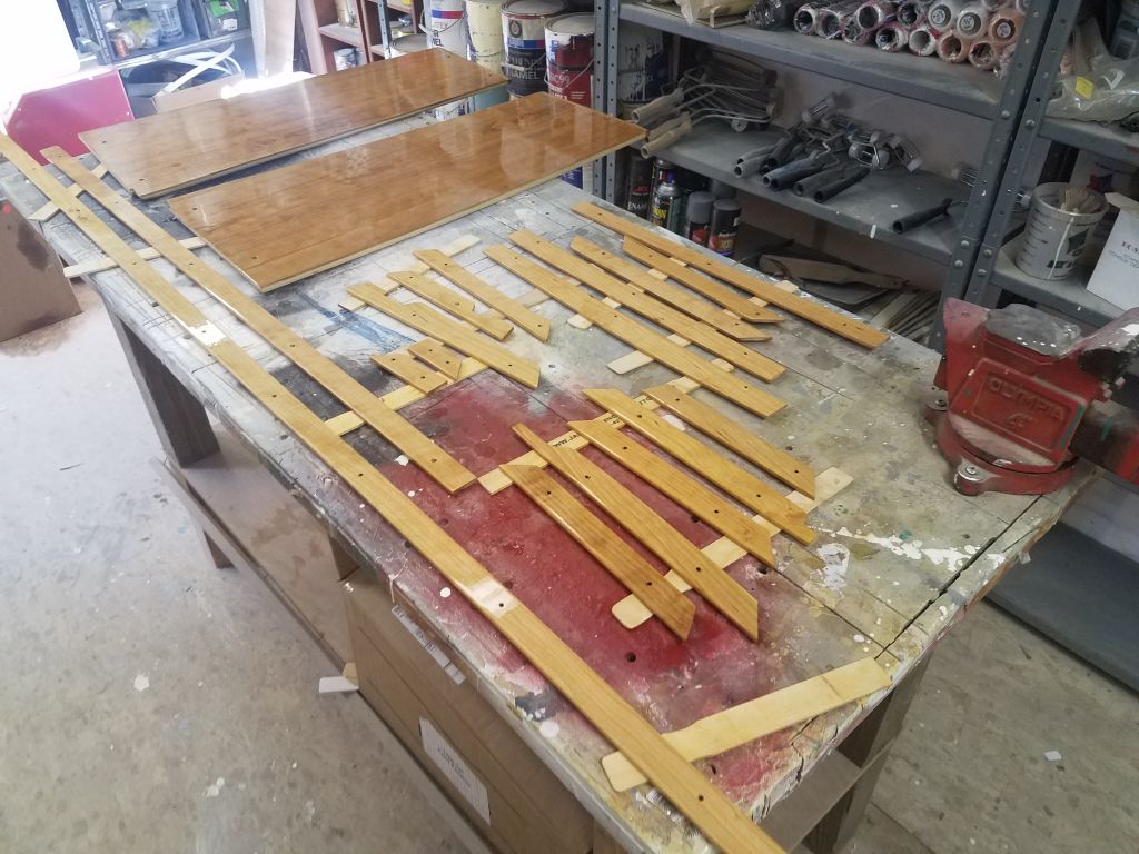
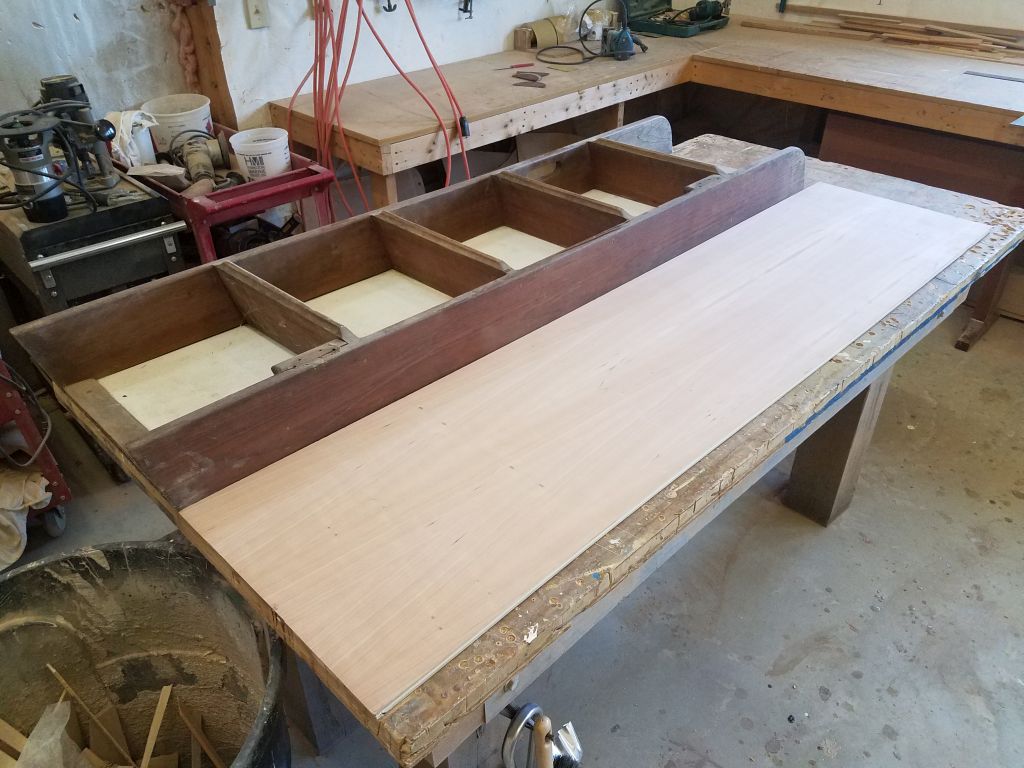
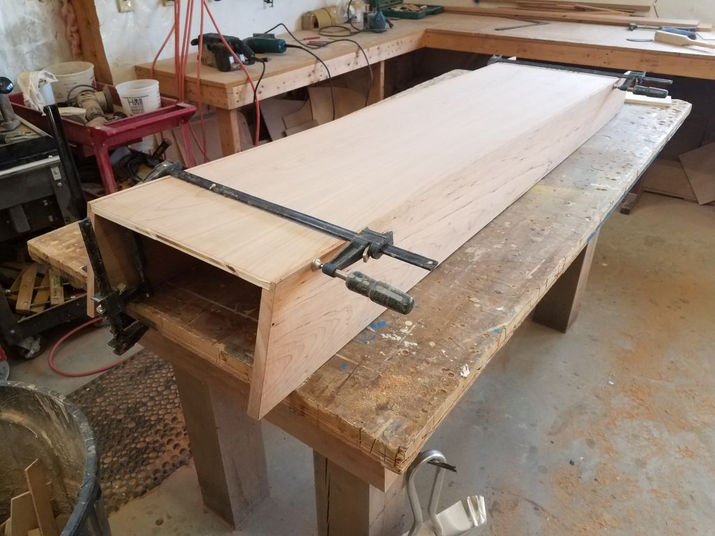
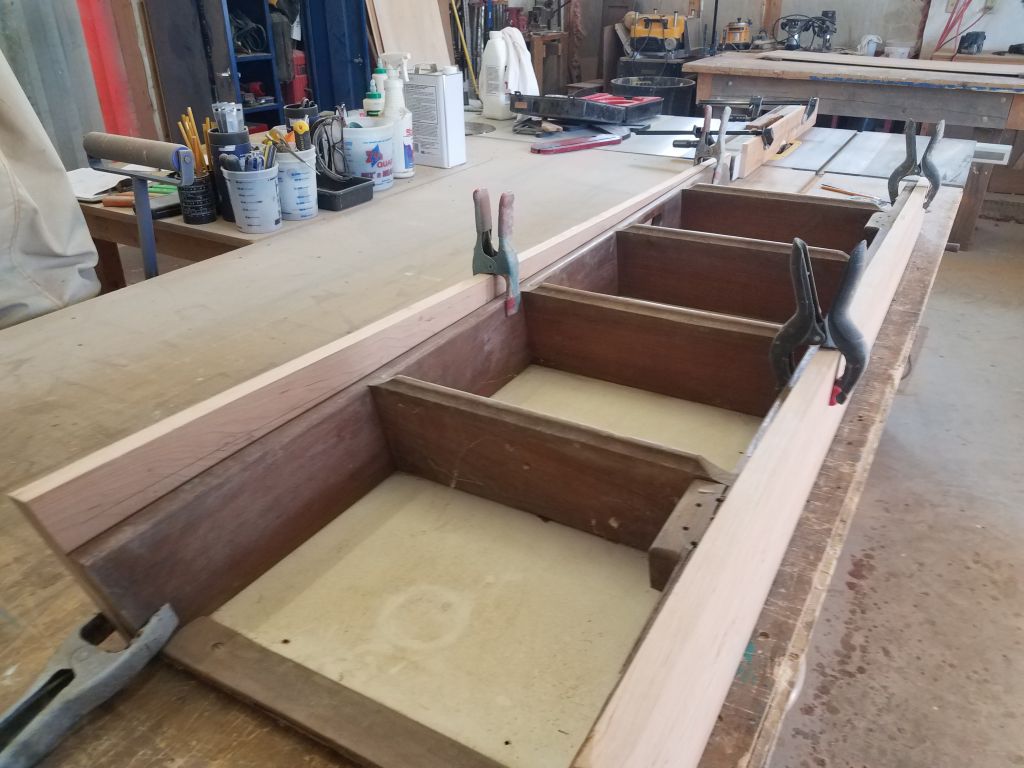
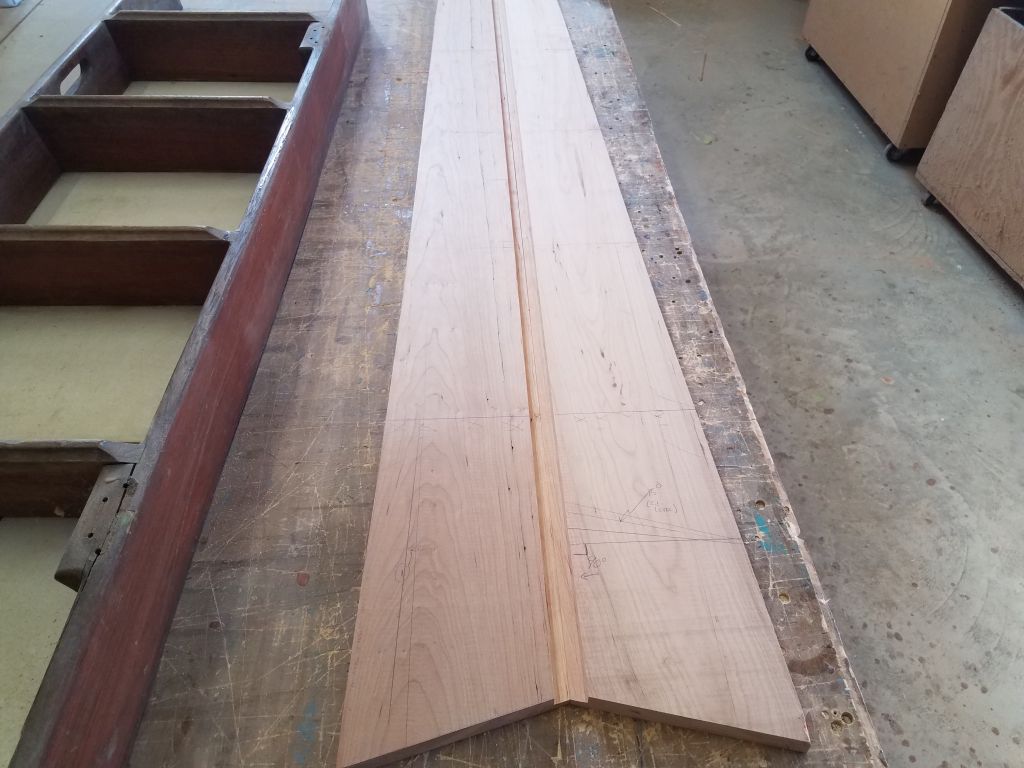
To this end, I spent some time laying out the new side rails on some pattern plywood, working within the known constraints of the cherry lumber I planned to use (much earlier, I’d set aside two wide, clear boards for this purpose) and with the desired improvements in the angle. This ultimately increased the width of the rails (and the depth of the ladder) by 2″ at the bottom, while keeping the original dimension at the top.
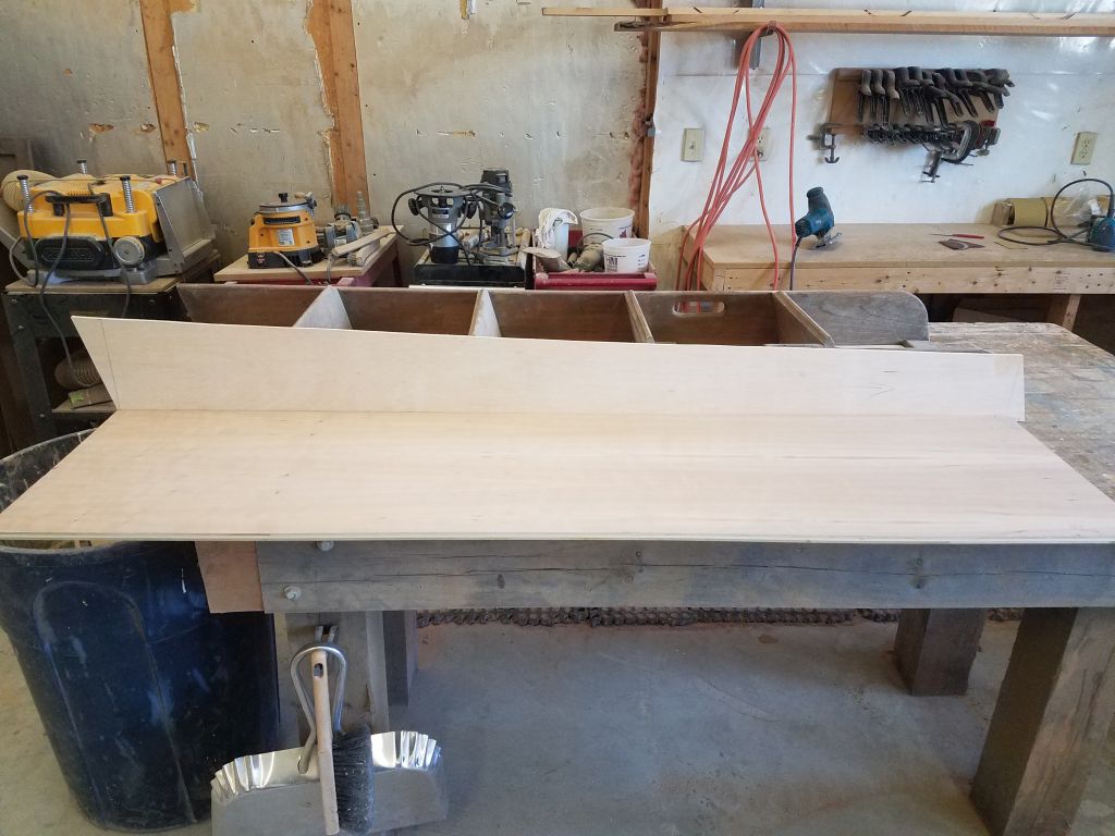
With a pattern in hand, I could trim the two side boards to the proper (but still over-length) length and then cut the new angled outer edge with a straightedge and a circular saw. I cut the angle on the bottom sides of the boards, but left the tops untrimmed for now.

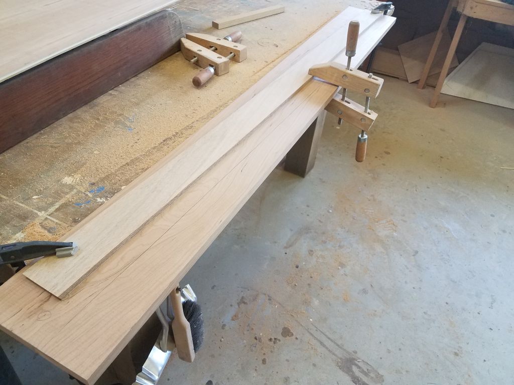
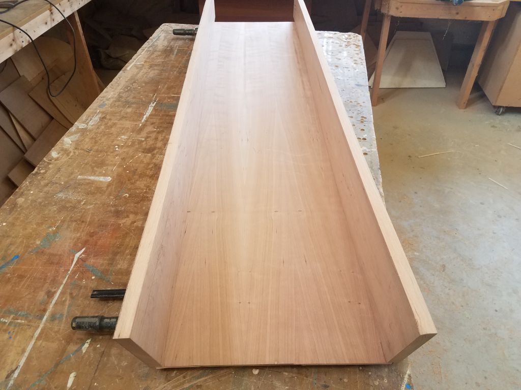
To cover the edges of the plywood back structure, and add strength to the whole assembly in its final construction, I laid out and cut rabbets on the back edges of both side rails, which would allow the 1/2″ plywood to sit flush within. I trimmed the plywood as needed to keep the ladder’s overall width where it needed to be according to the original ladder.
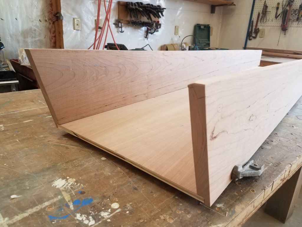
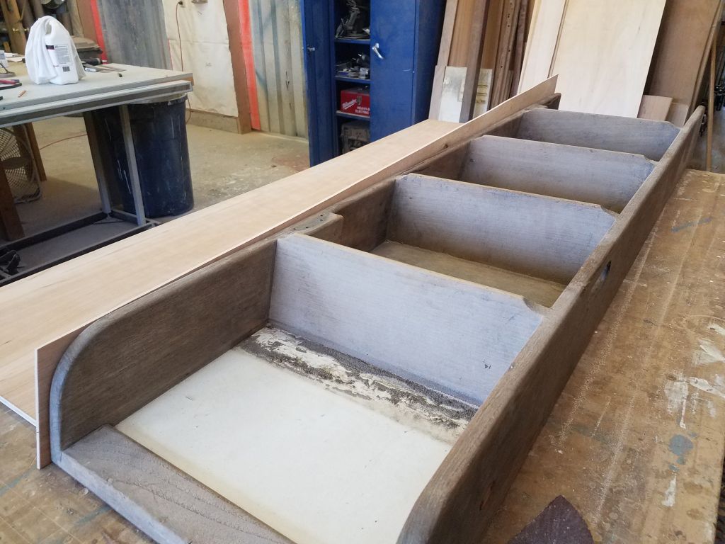
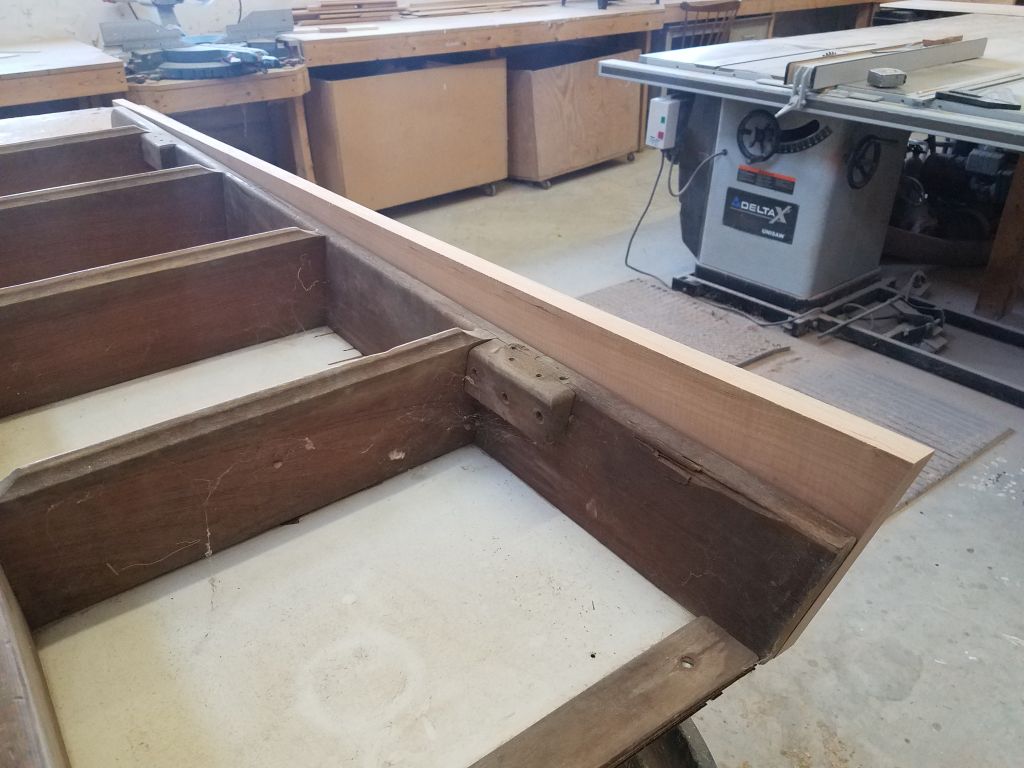
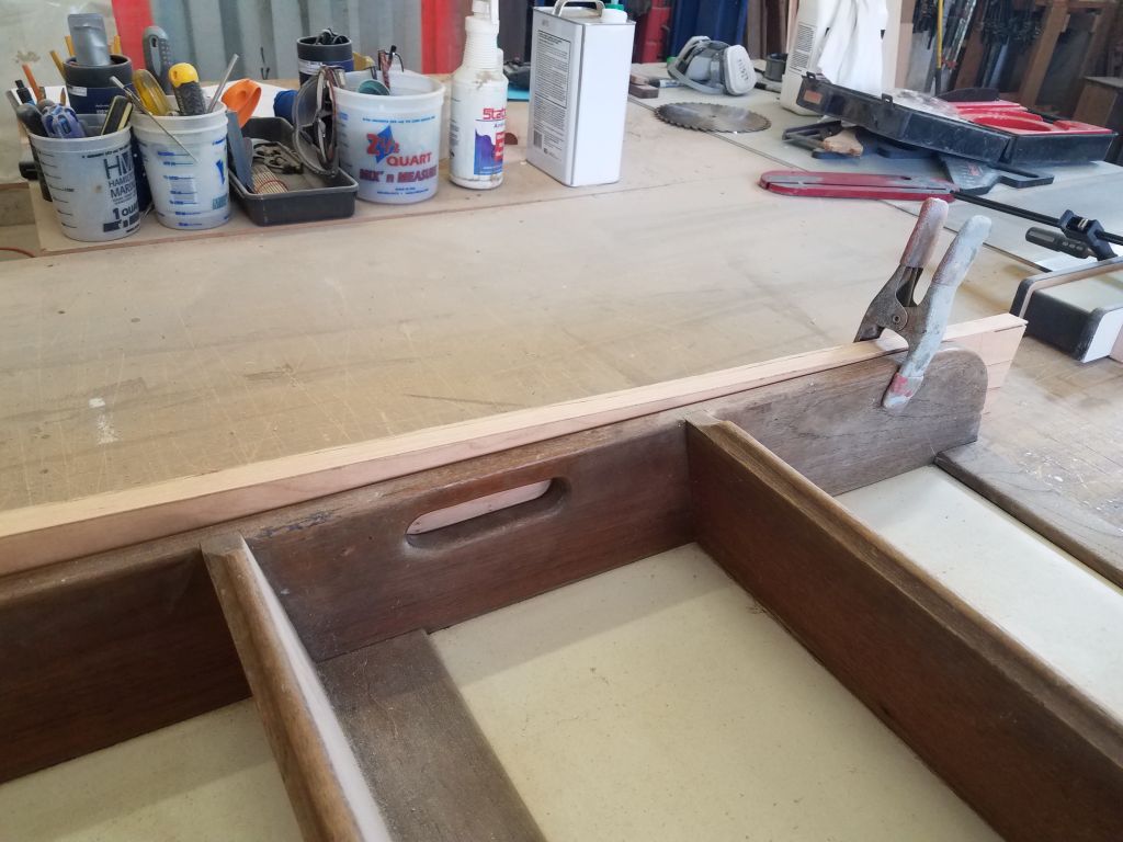
Now I clamped the new side rails against the original ladder, and, taking some alignment and measurements from the old ladder, transferred the treads’ positions to the new rails. I also transferred the position of the handle on the outboard side of the ladder, though later I moved the position closer to the edge of the new rail to match the offset of the original, as the new rail was an inch or so taller here now thanks to the improved angle.
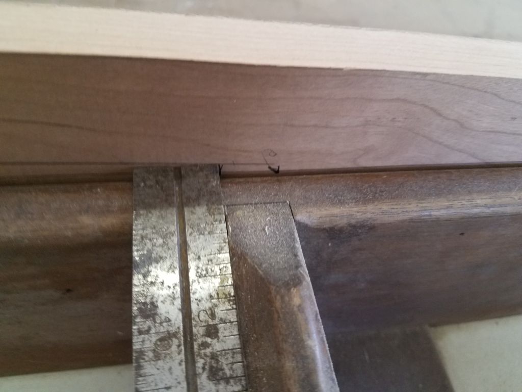
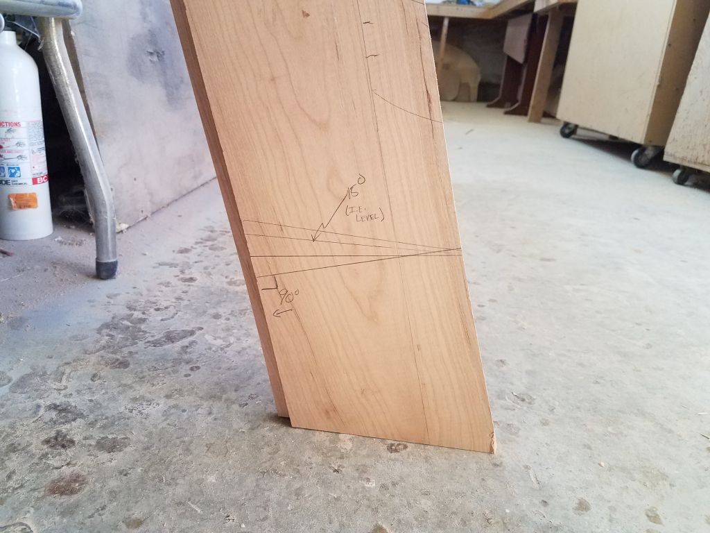
With the treads’ basic positions now marked, I wanted to incorporate a new angle to the treads, so that they angled down slightly at their back sides; the old treads had been essentially level, which didn’t lend itself to footing as secure as it might be with an angle to help the foot have somewhere to go. “Level”, in this case, meant parallel to the bottom of the ladder with its 15° angle, which I marked in a test portion of the board along with a few other options, including one where the new treads would actually be square to the back (straight) side of the ladder. With the test ladder rail propped up against the bench at its final angle, I checked the layout lines to see how they looked in proper perspective, trying to choose which angle worked best for the new treads. At the end of the day (figuratively and literally), I was leaning strongly towards the layout that was square to the backs of the rails, and went as far as to lay out the top edges of each tread location at this angle, but since time was out for the day it was a good opportunity to let the idea settle and mull the pros and cons before committing to the cuts required to support the treads in the side rails.
Total time billed on this job today: 8 hours
0600 Weather observation: 20°, clear. Forecast for the day: Sunny, 47°