

March 3, 2020
Scupper 254
Tuesday
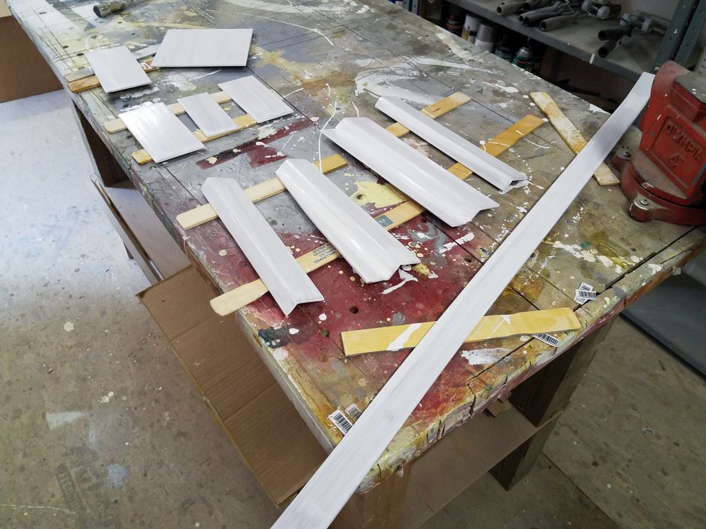
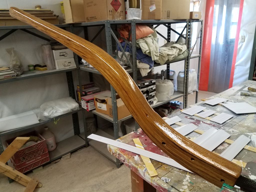
I continued work on the fiberglass liner cover plates as needed, which in this case meant lightly sanding and cleaning up the two newly-glued pieces from last time, and finalizing the sanded finish on the remaining sections as needed. After test-fitting the newly-extended section for the port side, I applied a coat of primer to all pieces. At the same time, I lightly sanded the tiller and applied a second coat of varnish.
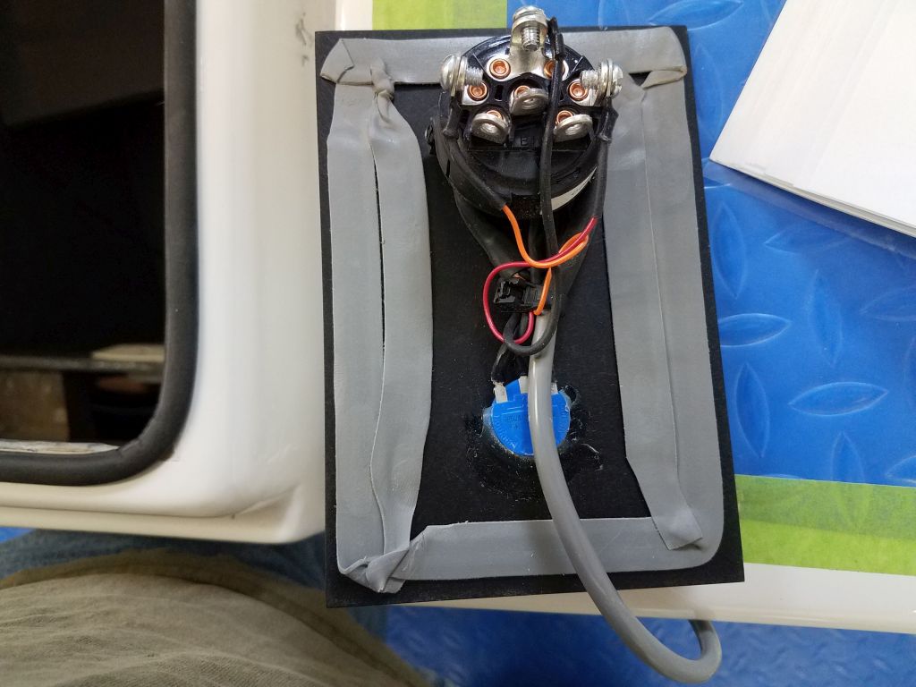
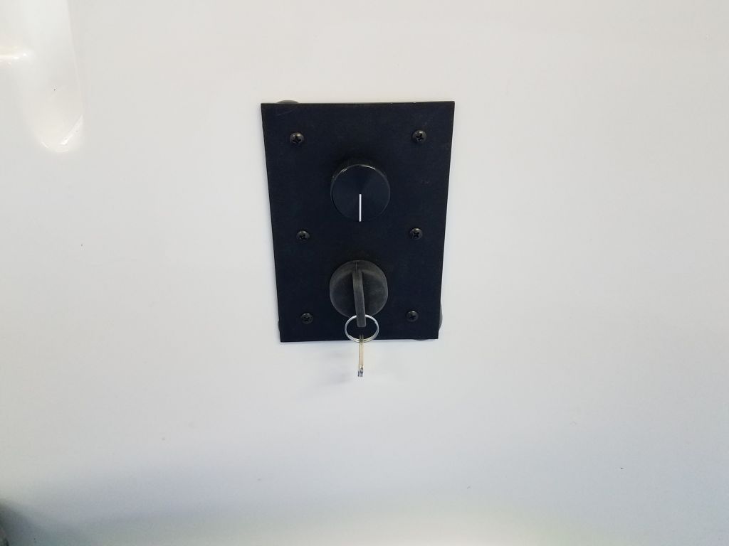
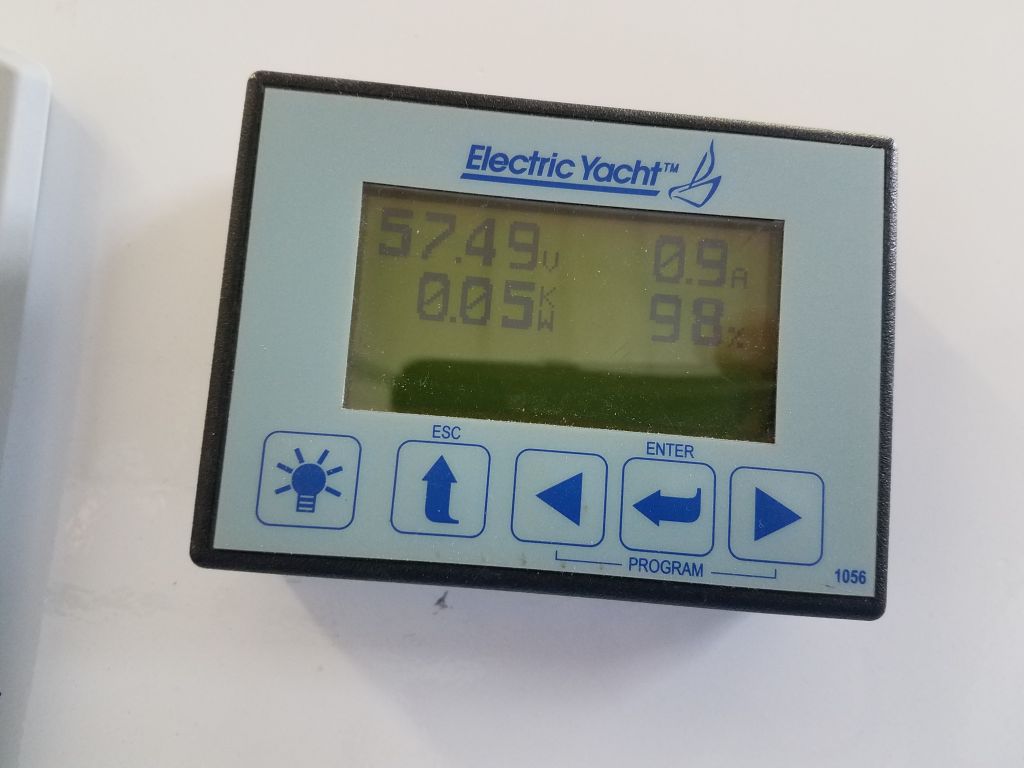
I spent some time on a more involved test of the electric motor and controller, eventually figuring out how to shift from forward to reverse (it wasn’t immediately clear that the key switch was the “gear shift”, and that turning it one way or the other selected the direction of the motor). I had to switch a pair of wires on the back of the key switch, as indicated in the instructions, in order for the key switch to work logically, with forward being forward and aft being reverse. With the boat on the hard, I had to severely limit how much I operated the shaft for now, lest I cause damage to the Cutless bearing, but in any event the propulsion system worked as it was supposed to in both directions.
Satisfied with the engine controls and that the wiring as as it should be, I permanently installed the control panel with butyl tape sealant and six screws.
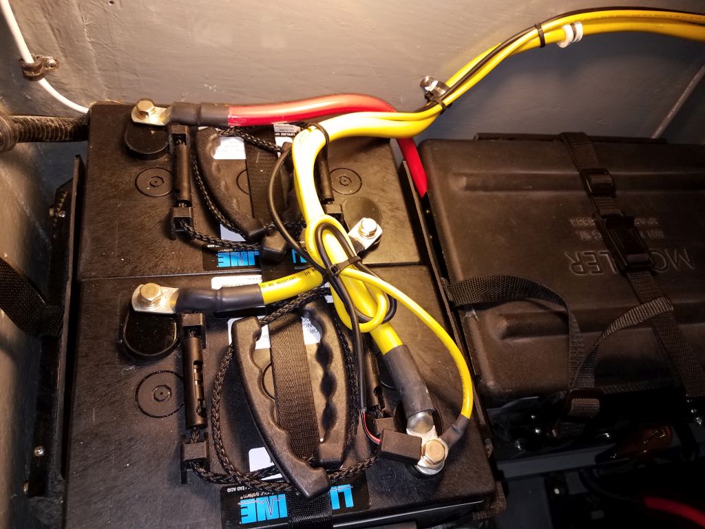
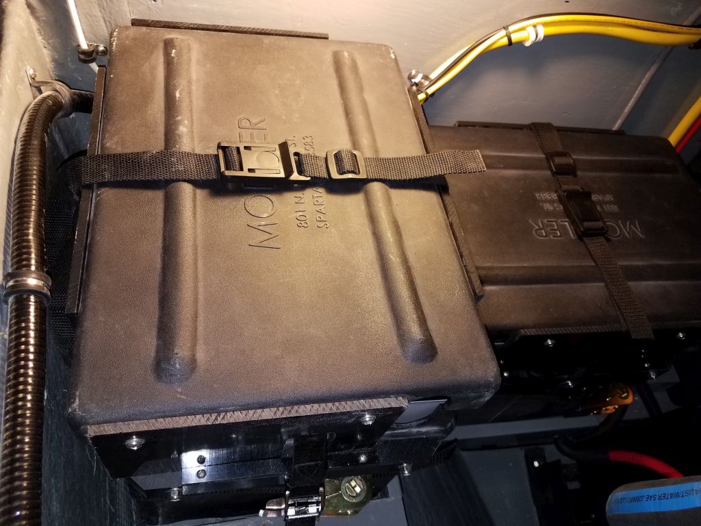
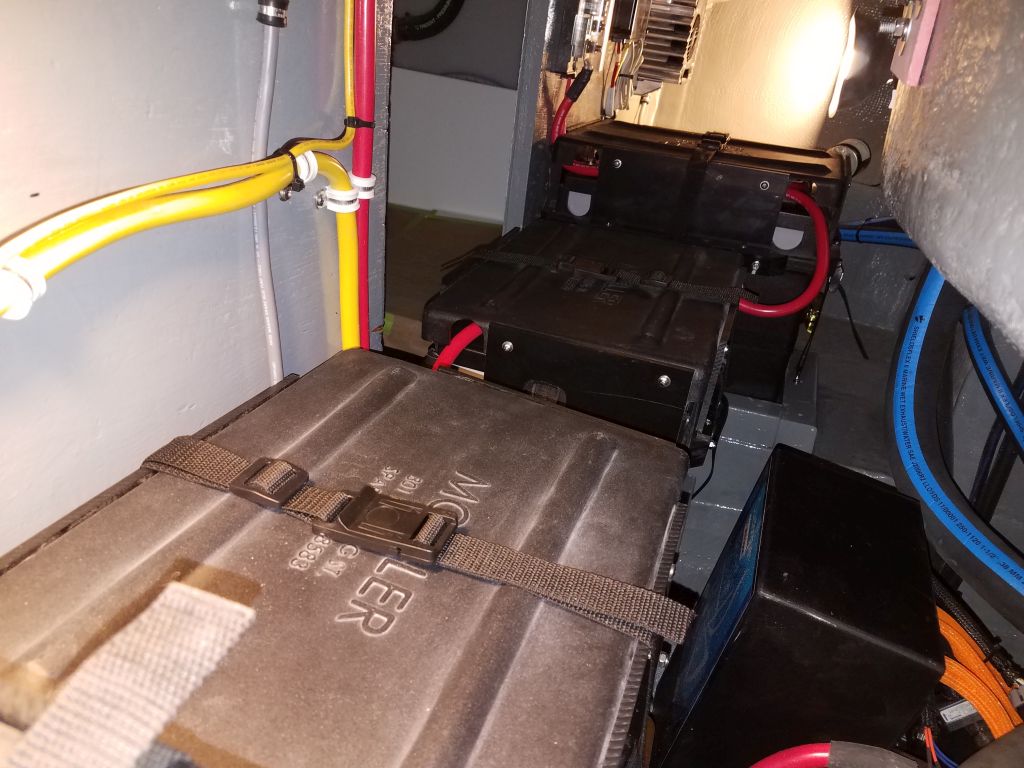
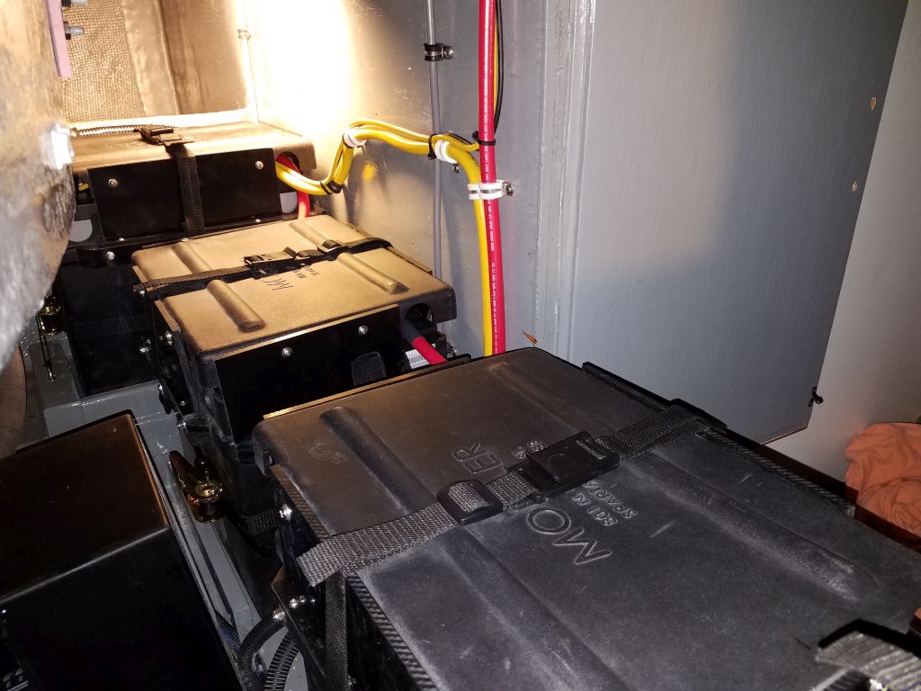
Before moving on to energize and test the charger for the engine battery bank, I took a few moments to finalize the wiring at the port outboard batteries, cleaning up and securing the charger and temperature sensor wires and securing the battery box top; I’d not been able to properly finish this when I made the final connections the other day.
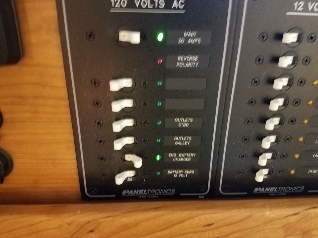
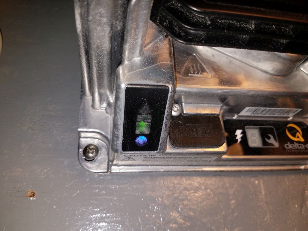
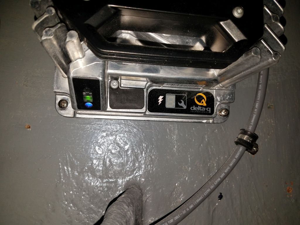
After plugging in the shore power, flipping the proper switches, and resetting the GFI outlet in the engine room (these seem to come pre-tripped when new), the battery charger powered up, and all lights that should have been lit were lit, and things that shouldn’t have lit up didn’t (i.e. error lights or codes). Once I’d confirmed proper operation, I left both this charger and its counterpart for the house battery bank energized for the rest of the day as a chaperoned test to ensure nothing untoward happened.
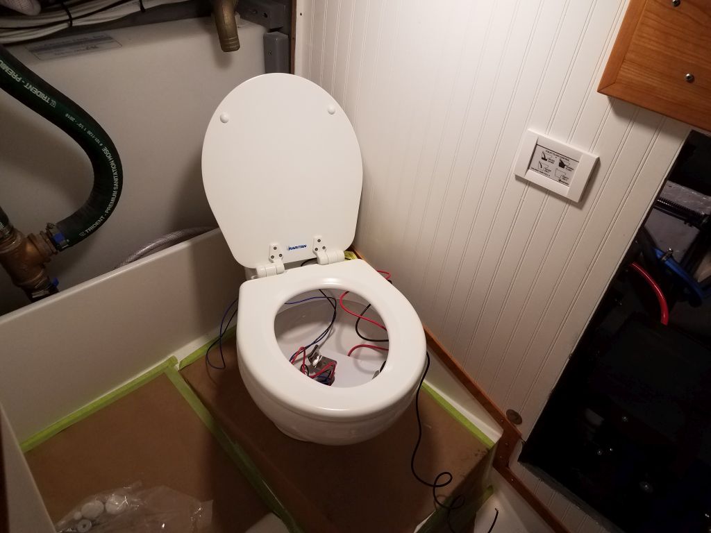
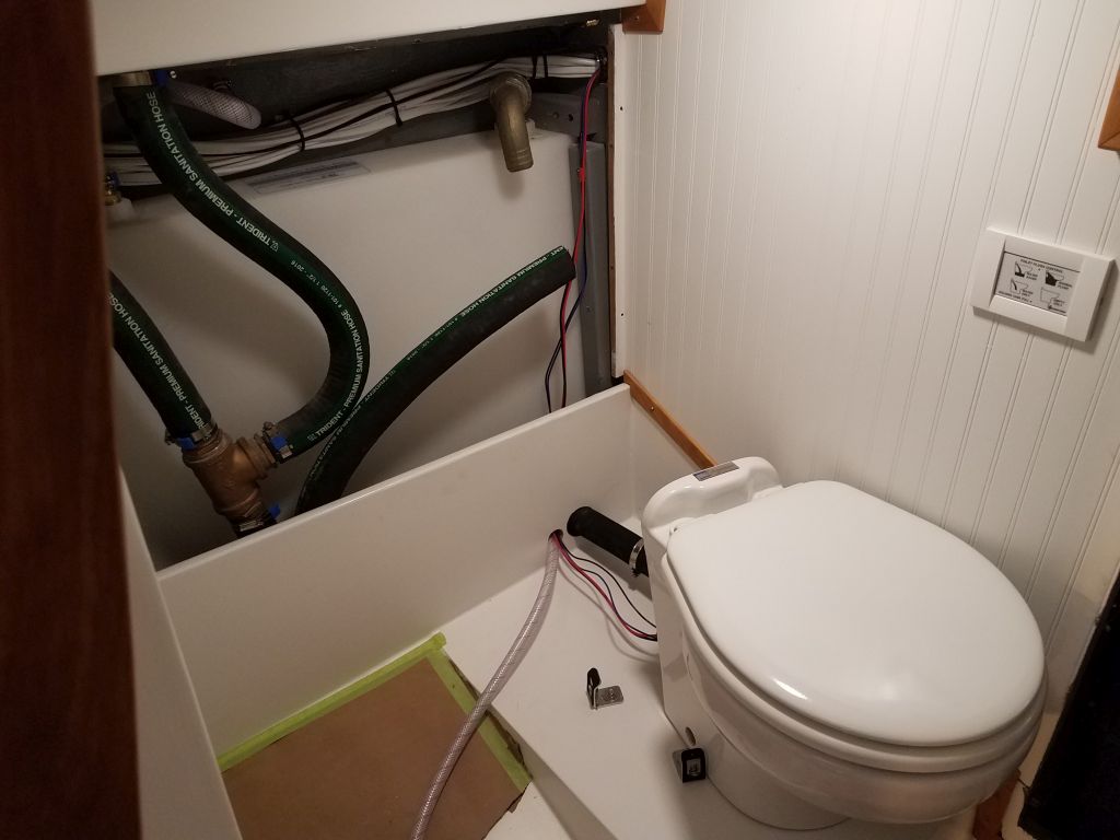
With the propulsion system and battery bank checked out and complete, the last major job aboard was to complete the installation of the head. I’d already done everything I could to prepare, so all that was left (one of those funny phrases in boat restoration…) was to install the throne itself, including water supply and discharge hoses and four wires.
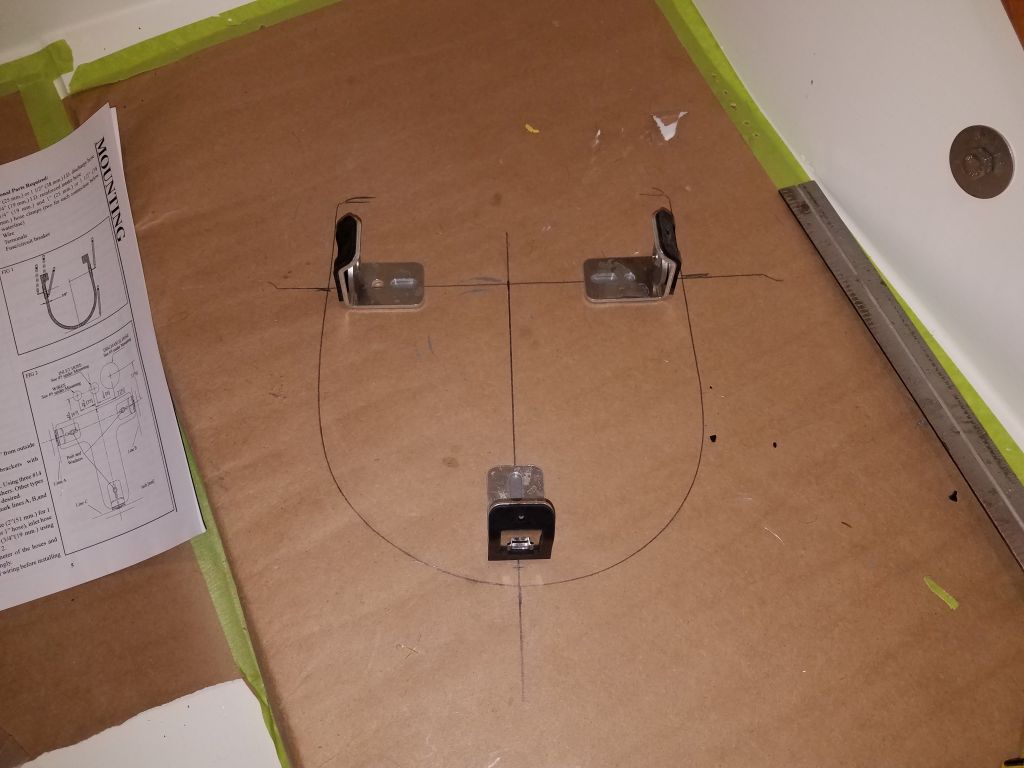
With the character and dimensions of the head platform and head compartment itself, I eventually settled on what I thought was a good position for the toilet bowl. I had to factor in arm and leg room, the shape of the nearby hull, space to allow the lid to open more than 90 degrees, and also leave room for the hoses to exit the back of the toilet. While the toilet was designed to have its hoses and wiring exit straight down from the back of the china bowl, and the bowl backed up close to a bulkhead, in this case there was no access, nor room, for this sort of arrangement, and I’d always known I’d have to run the hoses in a different way. My final location struck the required compromise between all the factors, and I marked the outline of the bowl right on the protective paper I’d had in the head during the project.

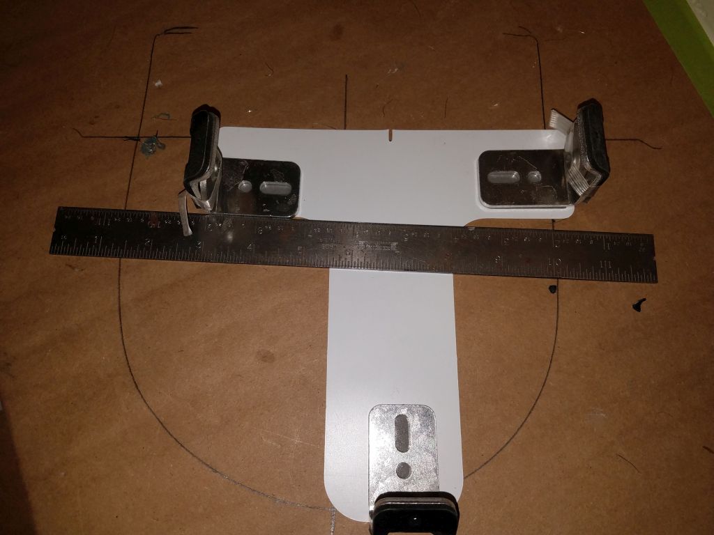
The bowl was to be secured to three hidden brackets that fit inside, with bolts that passed through holes in the bottom of the unit. As needed, I marked these locations to help align the three brackets, which came pre-stuck to a piece of cardboard that I supposed was to hold the brackets in the proper position and alignment, which could have been helpful if indeed the brackets were properly aligned and positioned on the cardboard, which they were not. So I removed the brackets from the cardboard (whatever they used to stick them on was extremely adhesive) and installed them according to my layout marks and in accordance with the instructions, securing them to the platform with the included screws and washers. Then, having previously noted the approximate locations where I wanted the hoses to run, I drilled two holes through the small bulkhead behind the platform and into the holding tank space, and with some effort eventually led in the heavy discharge hose, leaving both ends detached for now pending final head installation. The fresh water intake line I had led into the compartment some time before, and now had only to lead it out through its own new hole towards the toilet.


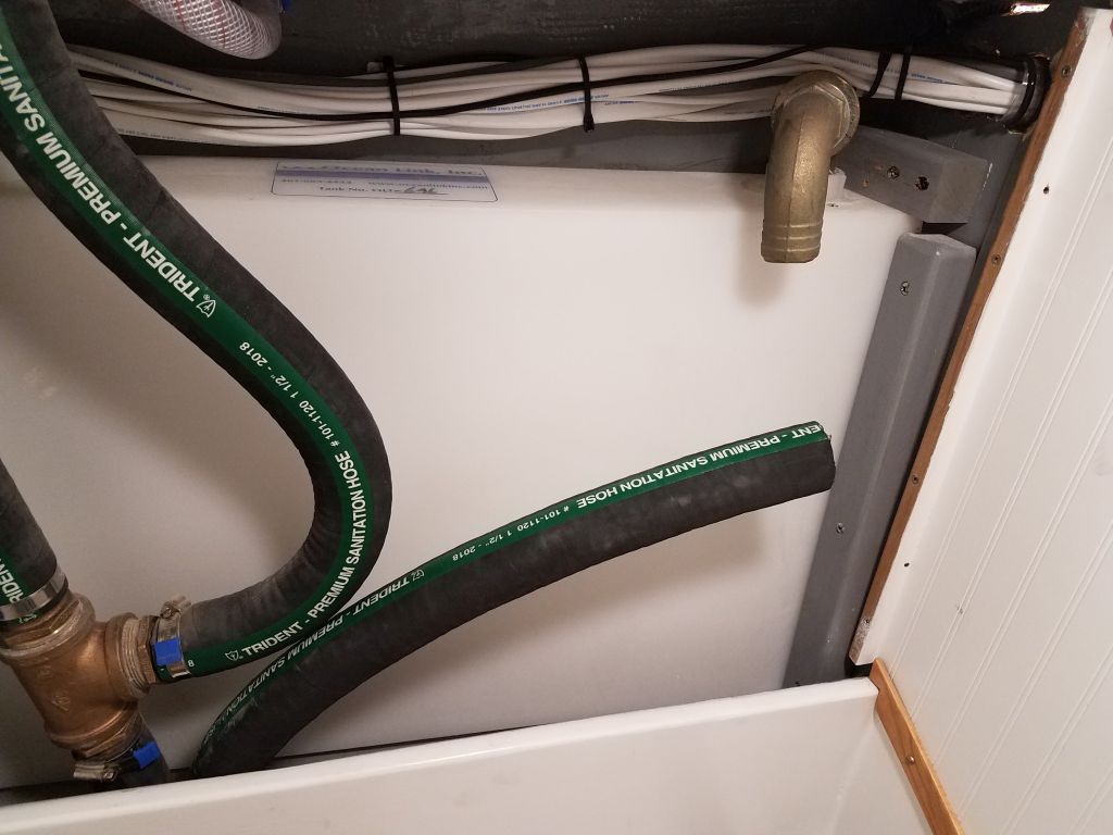
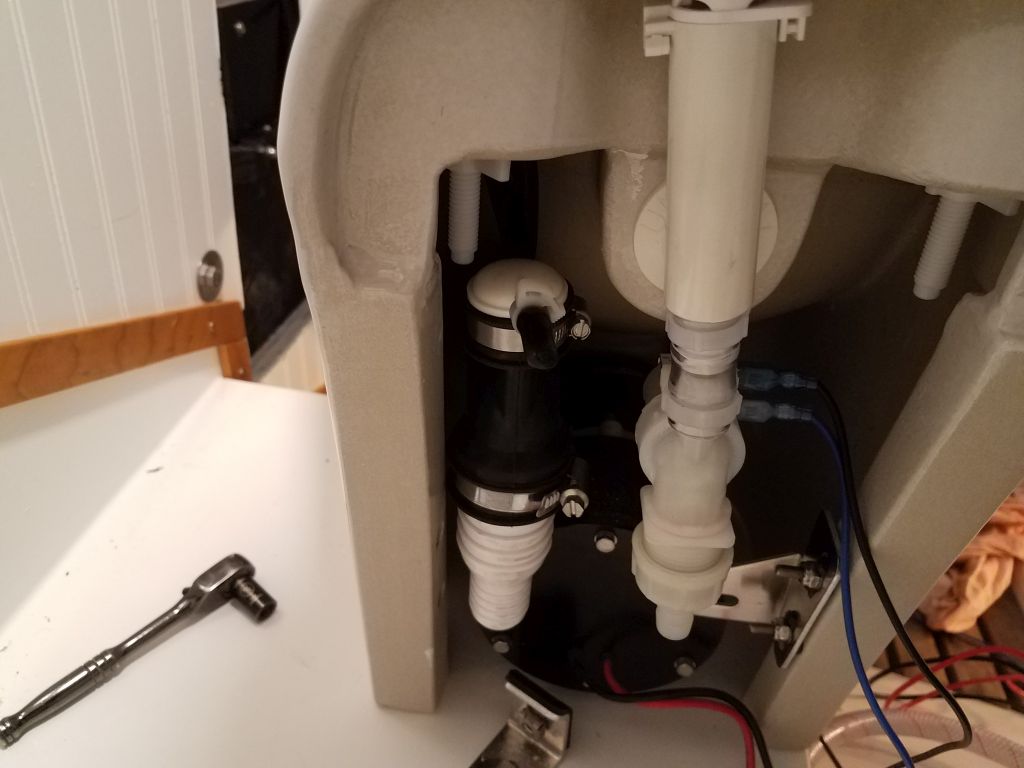
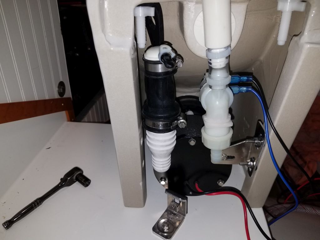
I had hoped and planned to complete the installation now, but I ran into difficulty with the discharge hose connection. As I noted before, the design intended this hose to lead straight down, and the discharge attachment arrangement inside the toilet bowl didn’t easily accommodate deviation from this engineered solution. There was flexibility in the discharge connection, but I found that with the hose attached and a fairly aggressive bend to lead out to the bulkhead, the rubber thingie inside the toilet tended to kink. At length, after trying various things, I came to the conclusion that I needed an elbow fitting in there in order to make the bend while keeping the discharge assembly happy, and since I didn’t have one on hand I’d have to postpone final installation till a little later. Fortunately, there was (or, I should say, appeared to be) ample vertical clearance to accommodate an elbow, so I hoped that it would work out well once I had it on hand. I would have preferred to avoid the extra fitting, but so it goes with anything on a small sailboat (or, I imagined, any boat).
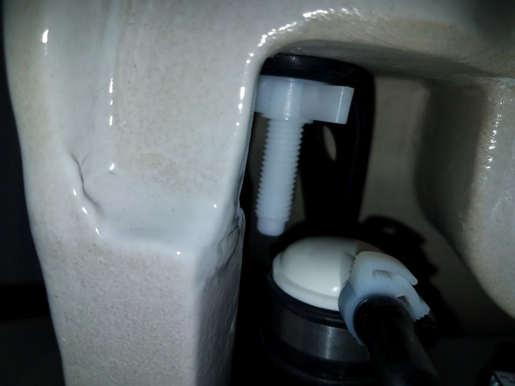
During this process, I’d found that it looked like it would be beneficial if I pre-installed the rubber bracket included with the discharge assembly, and which was designed to be secured from above by one of the bolts holding on the toilet seat, so I took care of that now to ease angst later on.
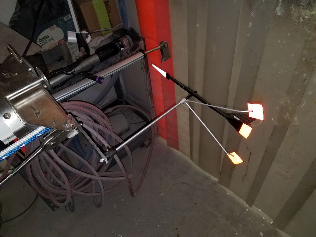
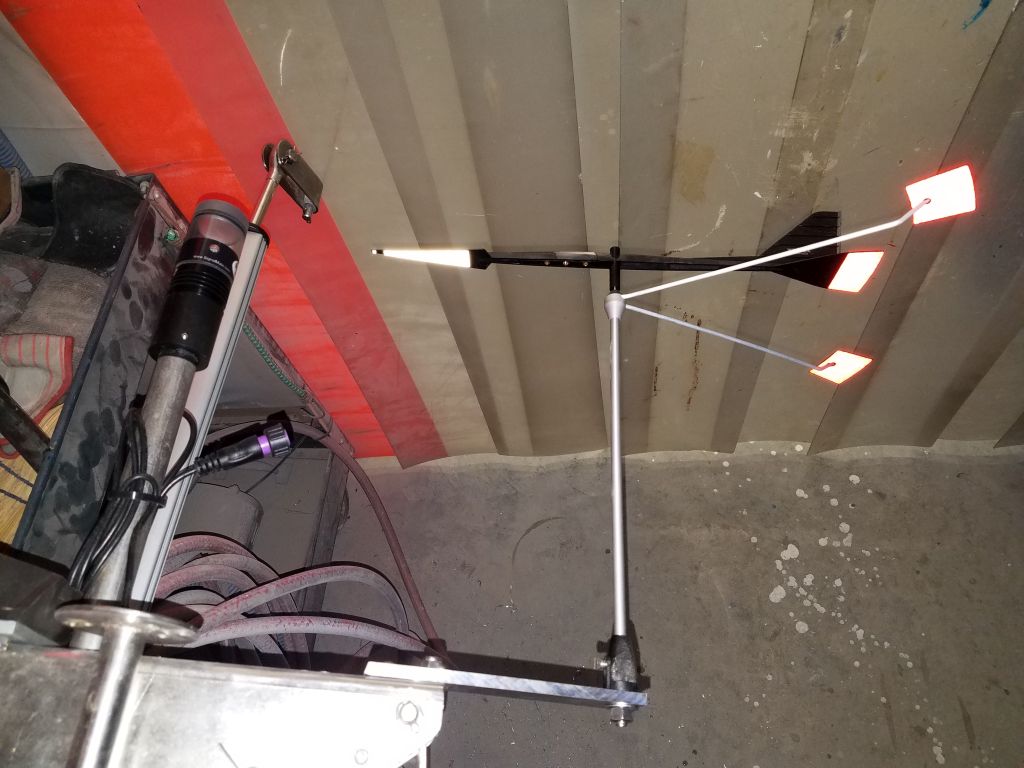
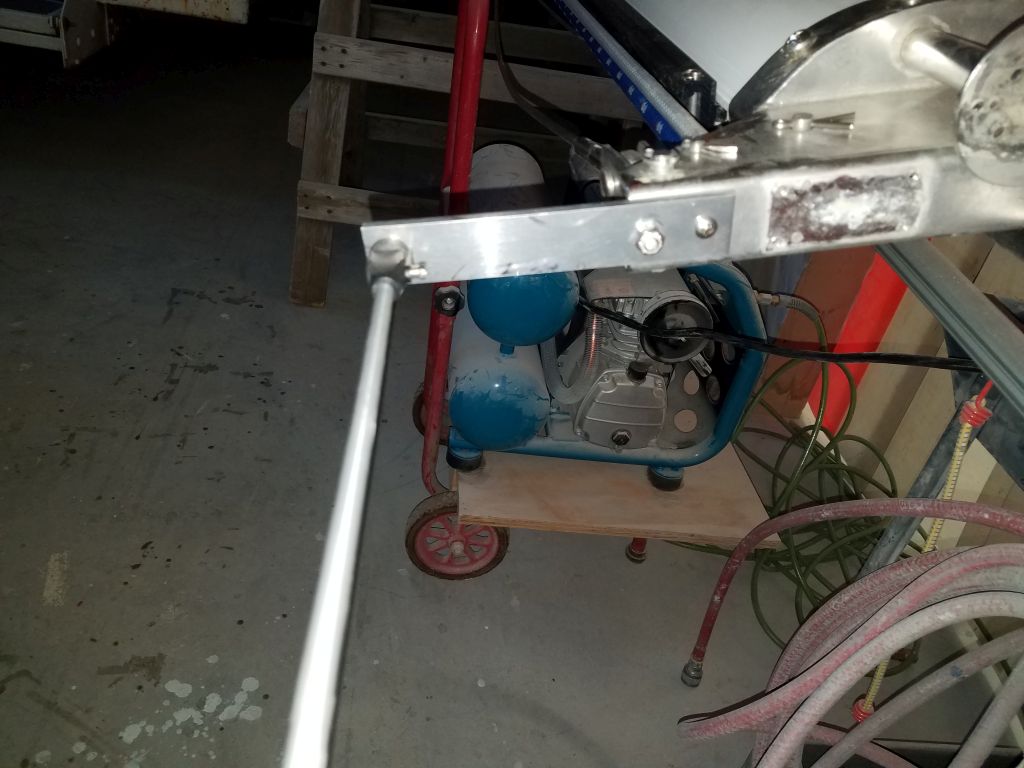
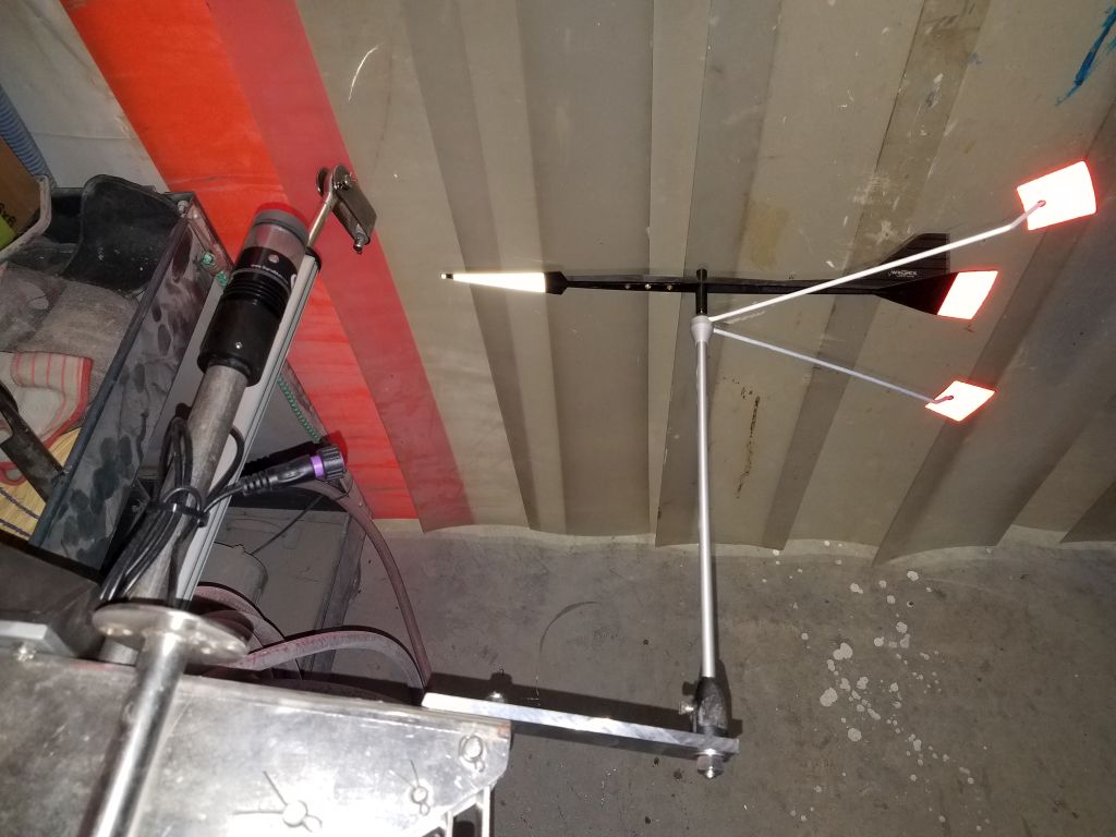
Having taken the head as far as I could for the moment, I finished up the day by installing the new aluminum bracket I’d purchased for the masthead, and completing the Windex installation. I secured the bracket to an existing hole in the masthead unit, along with an additional screw to keep it from twisting, and bolted the Windex mount to its after end, giving the vane ample clearance with the lights forward. I removed the vane for safekeeping.
Total time billed on this job today: 8 hours
0600 Weather Observation: 34°, partly cloudy. Forecast for the day: Mostly sunny, 51°