

September 17, 2018
Scupper 61
Monday
I’d originally planned on removing the rudder at some point when I lifted and moved the boat, since there was not enough clearance to the shop floor with the boat in the shop to allow a complete removal of the shaft. However, for the moment I planned to keep the boat where she was, and after some consideration I decided I could attack the rudder repair now without completely removing it–barring unforeseen circumstances, of course.
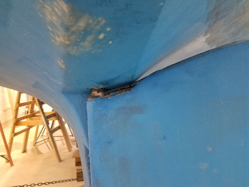
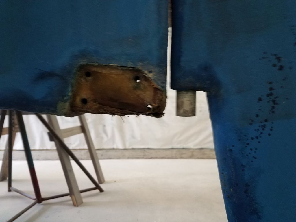
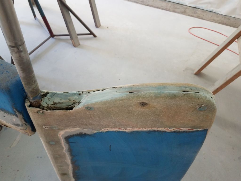
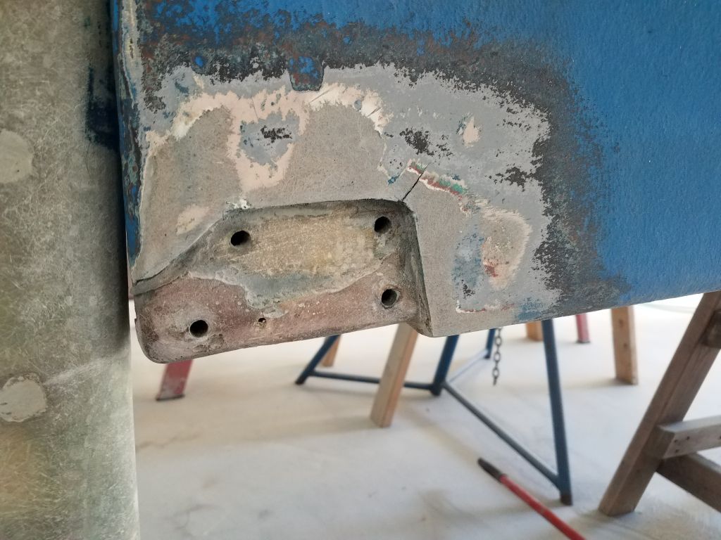
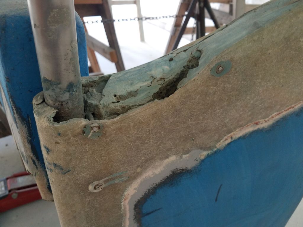
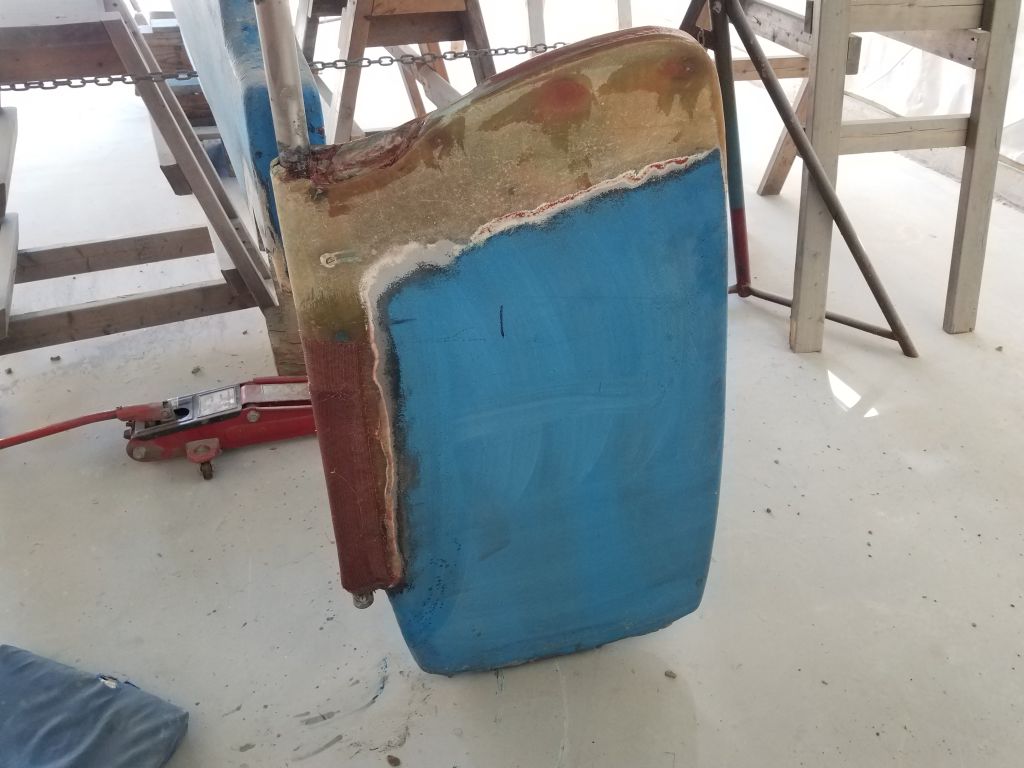
The main problem with the rudder was at the top edge, where the blade had hit the hull over the years since there had been no rudder stops installed in the steering system to prevent such an occurrence. This had crushed the fiberglass and crumbled the interior structure of the rudder (basically a mix of solid putty).
(Photos from earlier in the project)

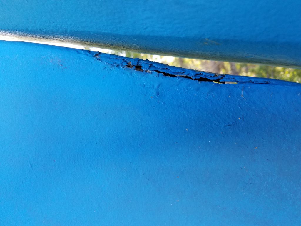

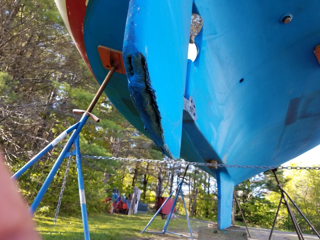
There was also a crack along the seam at the centerline on the leading edge of the blade–a common issue with rudders on many boats–plus additional damage to the bottom edge of the blade, which would also require some rebuilding work. (Photos from earlier in the project)
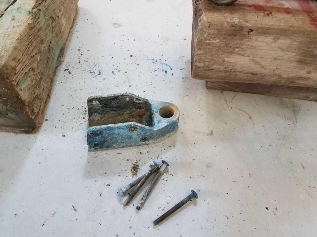
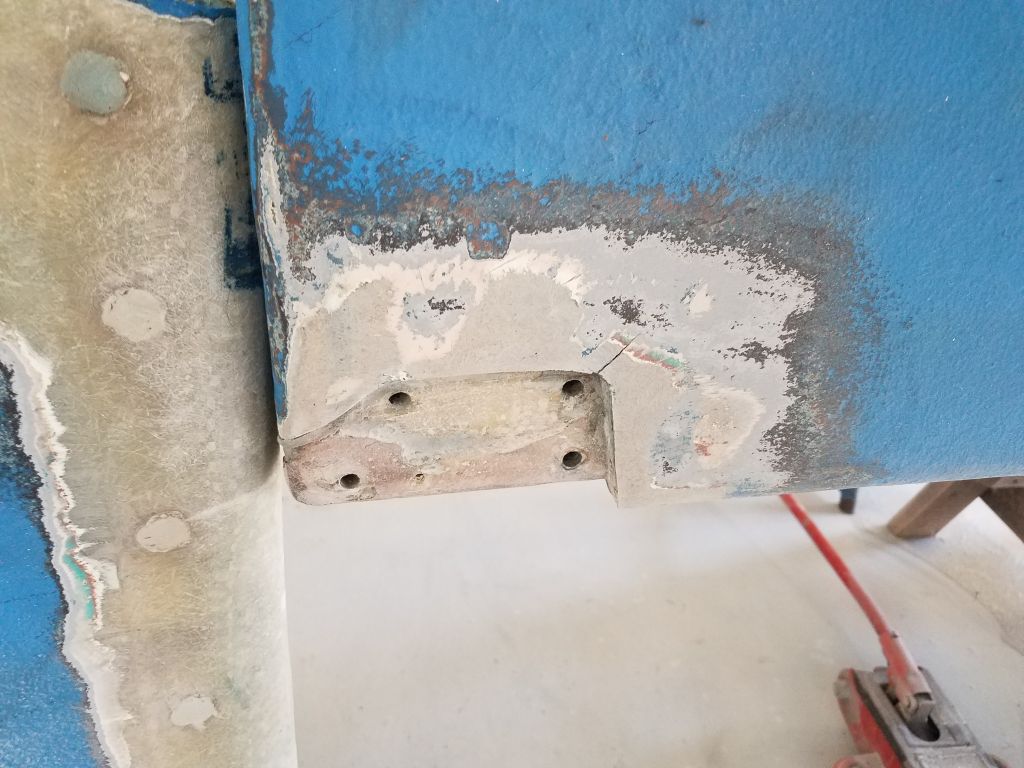
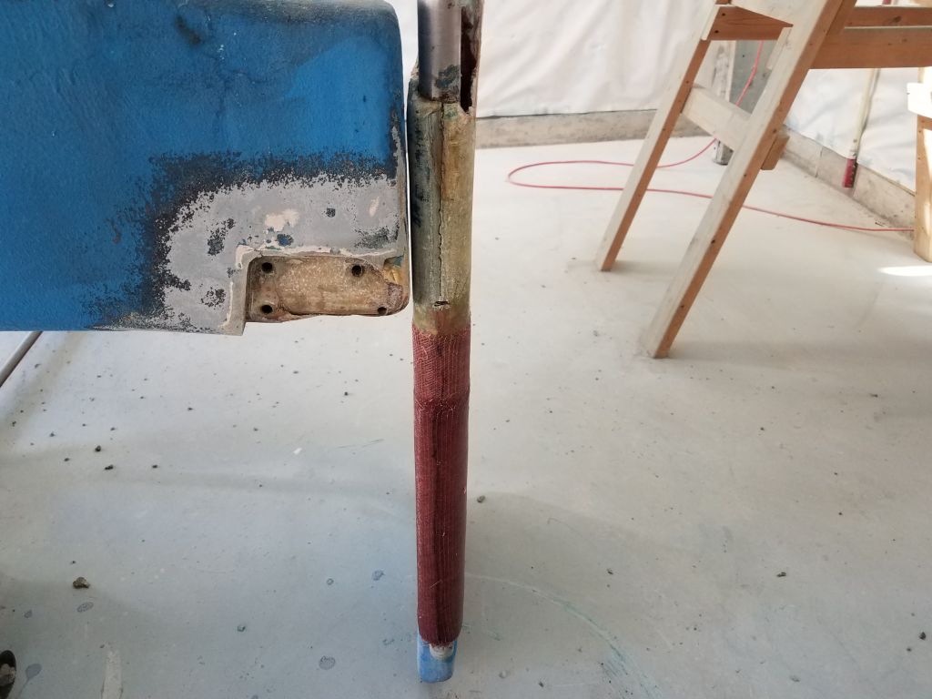
A bit earlier in the project, I’d prepared for the rudder’s removal by releasing the interior stuffing box nut and partially removing the bolts securing the bronze shoe on which the rudder shaft rested.
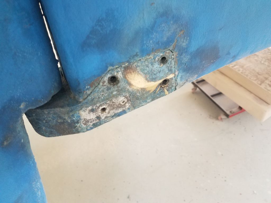
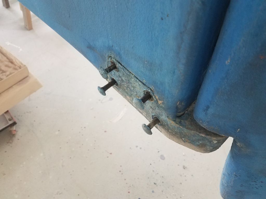
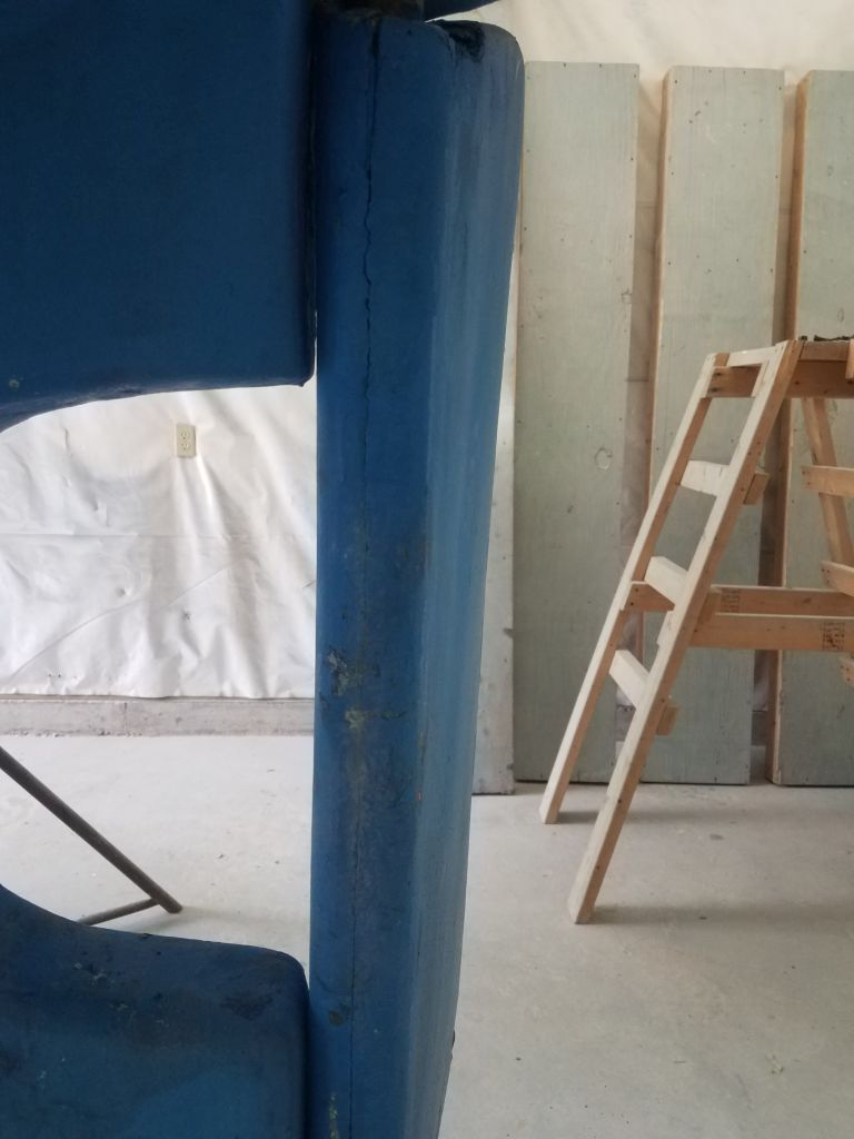
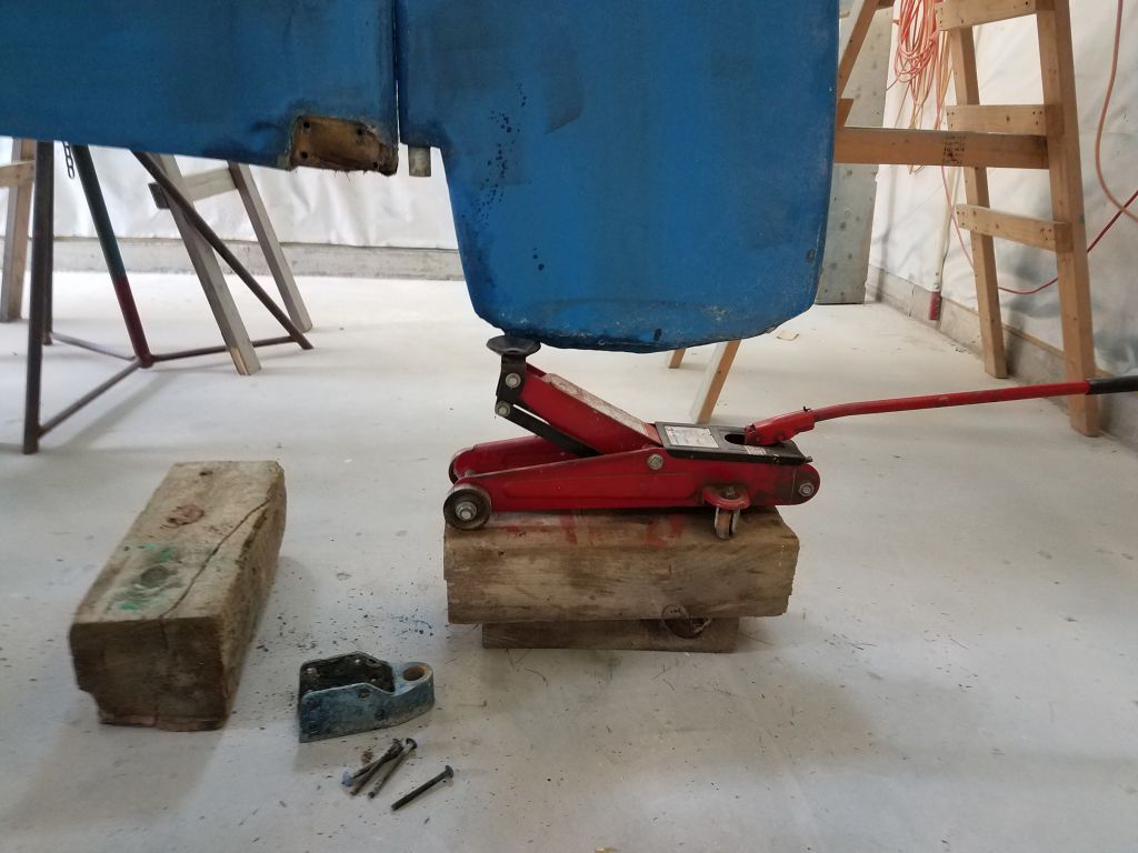
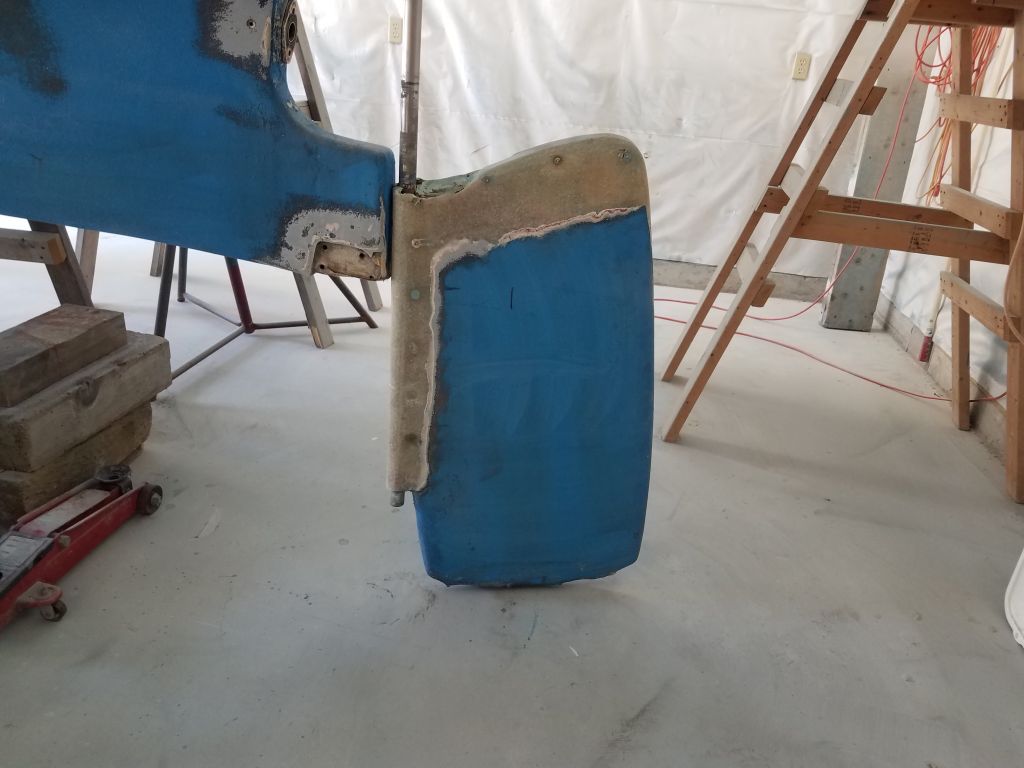
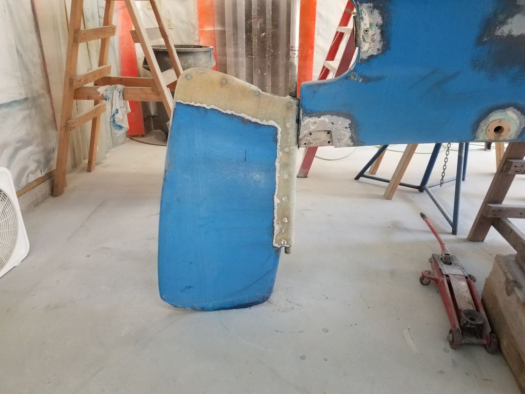
I set up a jack beneath the rudder to help me lift it off the pintle on the bronze shoe, and also to help me control the rudder’s descent. There was little clearance to lift the rudder given its relatively tight fit against the shape of the hull, but it was enough to ease the pressure on the shoe and allow me to remove the bolts, after which the shoe dropped to the ground of its own accord; there was only a little bit of silicone sealant behind it. Then, with relative ease, I could lower the rudder the rest of the way to the floor (after dropping it partially and removing the jack and blocking).


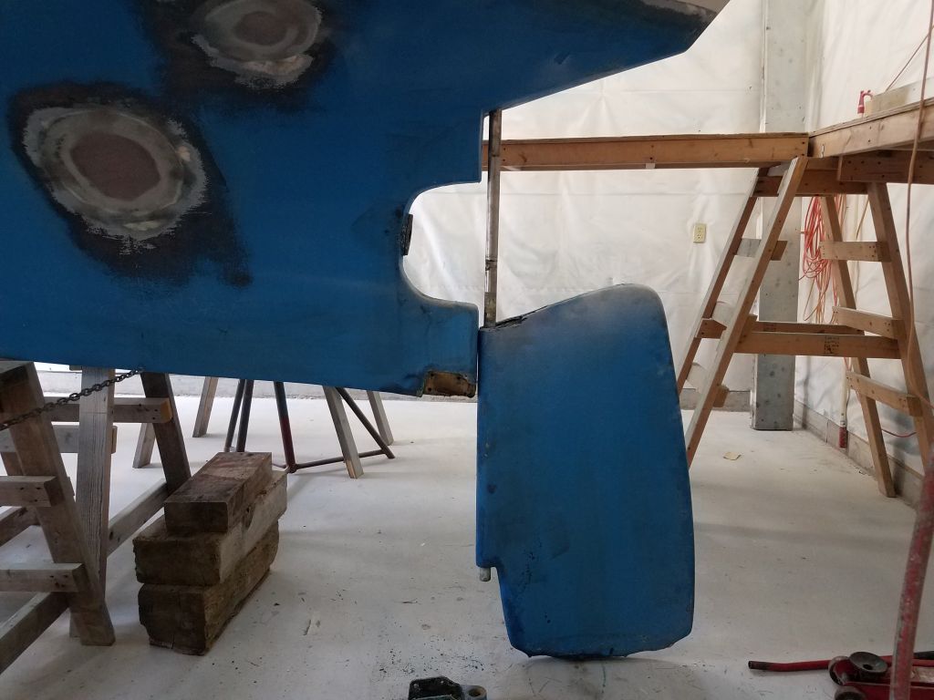
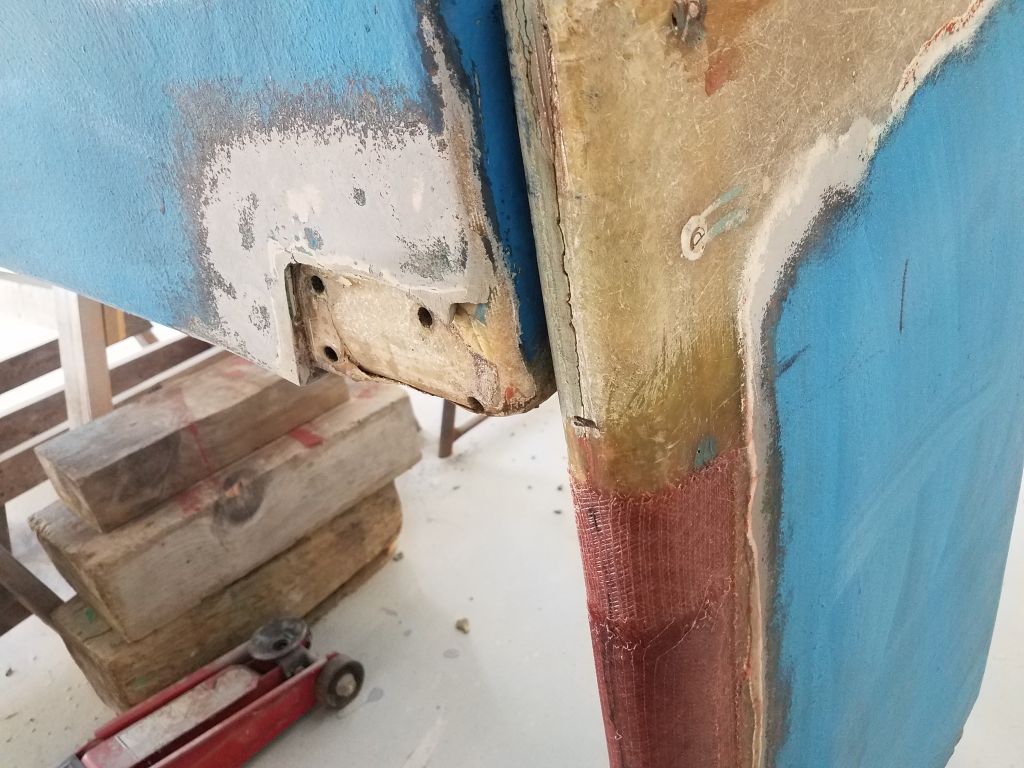
With the rudder down, I could access the top part of the blade–the most-damaged area–and also the leading edge, at least roughly half at a time. I hoped the scope of repair would fit within the limitations of the access, which indeed it appeared it would. The bottom of the blade I could deal with later, once I’d dealt with the top and leading edge.
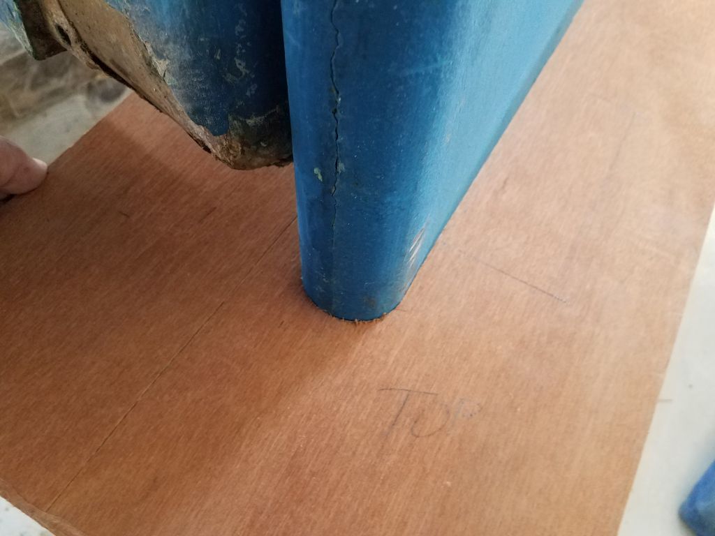
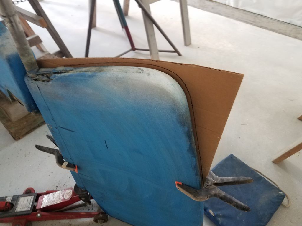
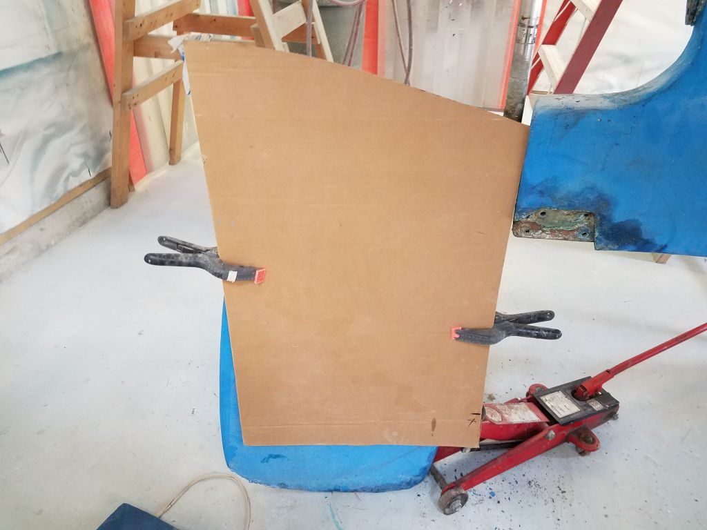
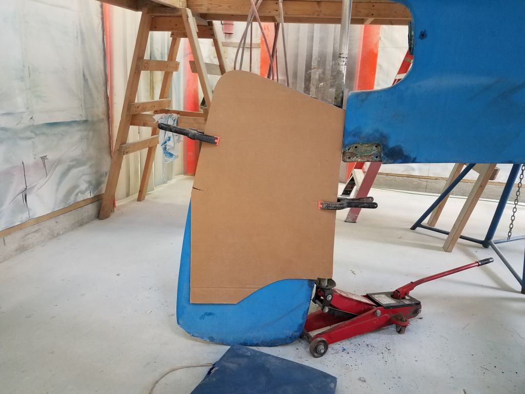
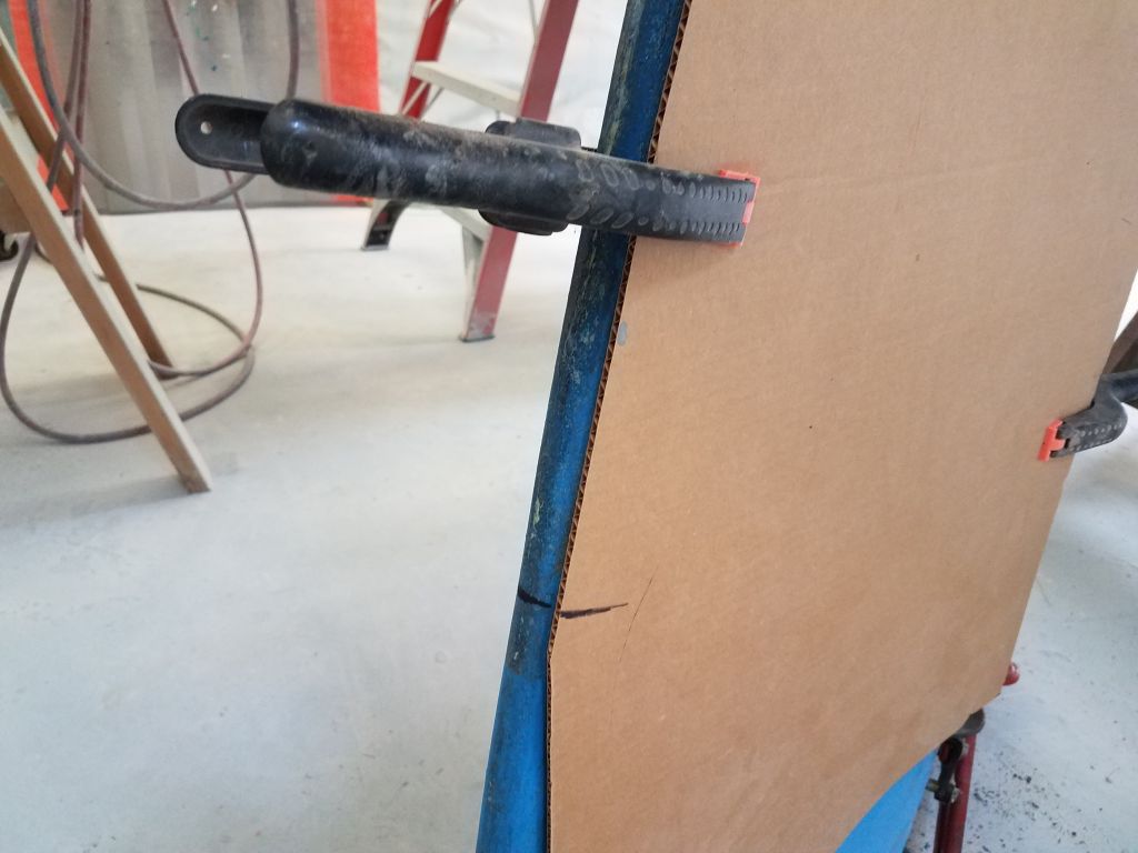
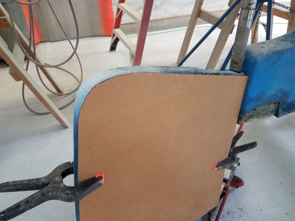
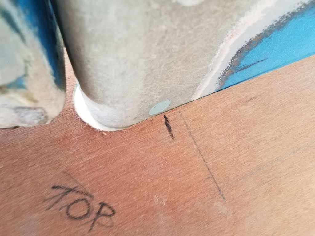
Clearance between the rudder and the skeg and hull was tight, and there was no room to add extra material to the rudder in the course of repair, particularly at the leading edge, which had virtually no clearance between it and the skeg. So to reinforce the cracked, curved edge, I’d need first to remove sufficient material to accommodate the thickness of new reinforcement. To ensure that I maintained the existing shape and contours, I began by making a simple template–first from cardboard, then eventually from 1/4″ plywood–of the leading edge. This would guide me as I ground off material and built up the new.
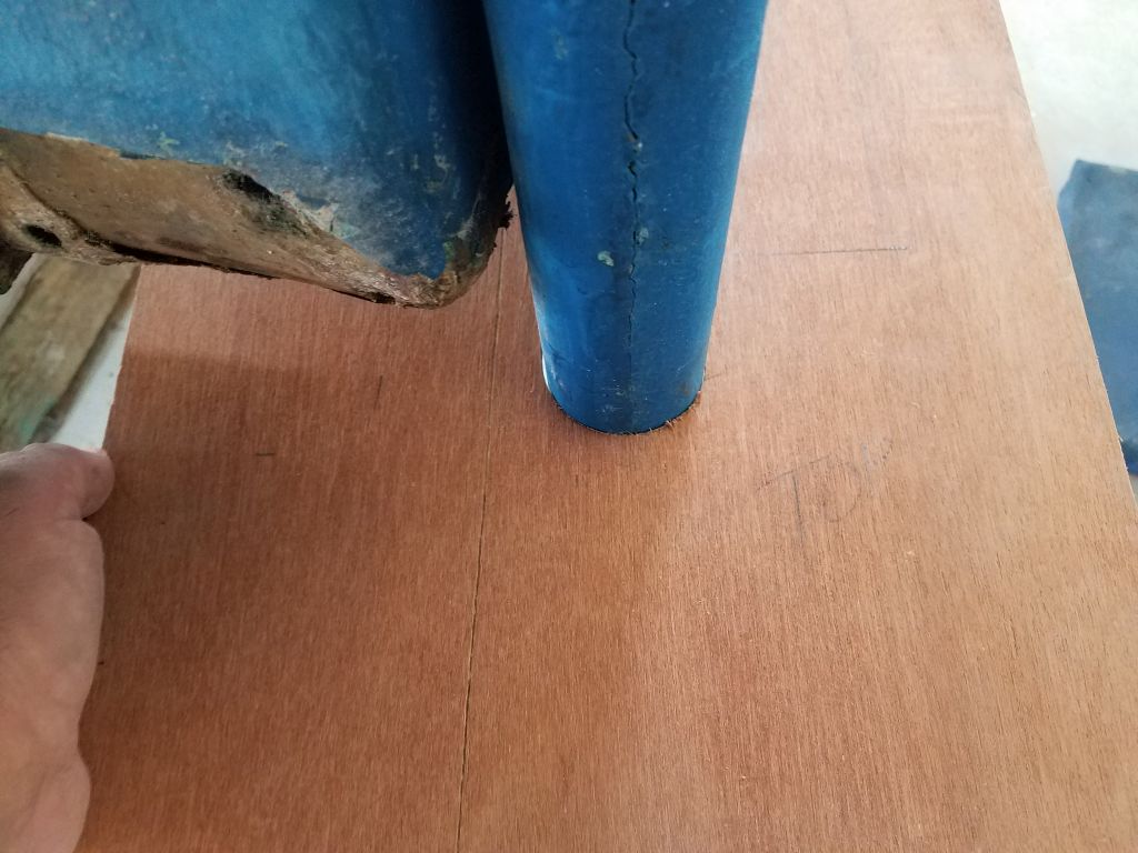
I also made a quick cardboard template of the shape of the top of the rudder, using the relatively-intact starboard side as my guide. The template would help me keep the rebuilt top in the correct shape, though this wouldn’t be much of a challenge since the top of the blade was basically a straight line from the rudder shaft aft to where it curved down to meet the trailing edge.
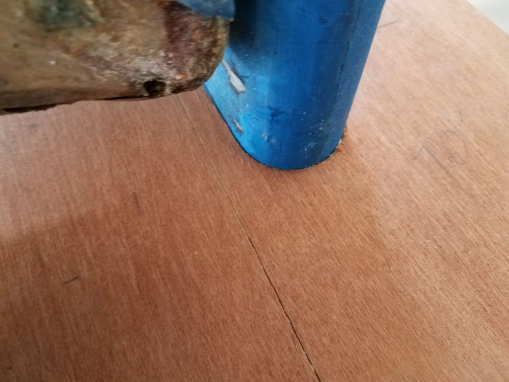
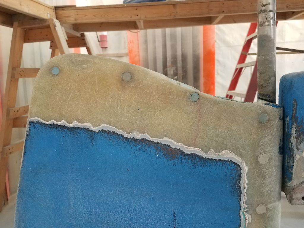
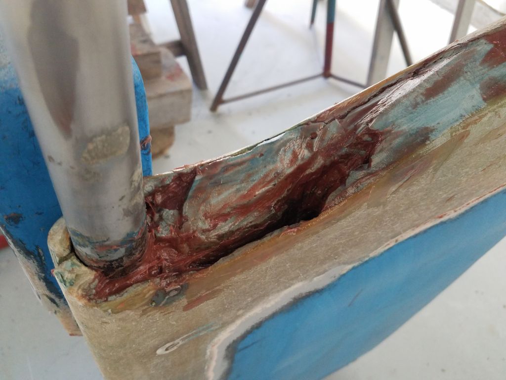
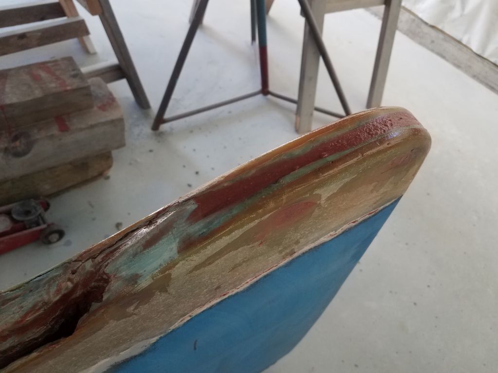
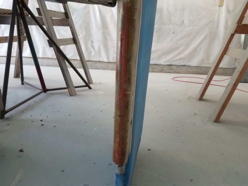
Templates complete, I ground the leading edge of the rudder as needed to remove paint and gelcoat, and also deep enough to accommodate several layers of fiberglass that I planned in order to better reinforce the cracked edge. I ground a bit into the crack running along the edge (the crack was simply where the two halves of the rudder came together but had been inadequately reinforced). At the top of the rudder, I ground into the damaged areas enough to remove all loose fiberglass and the damaged filler in between, and also sufficiently down onto the blade to allow room for new fiberglass that I’d wrap over the top during the rebuilding process. The round areas lining the edges of the rudder are filled areas covering the heads and bases of bolts that someone had installed long before in an attempt to reinforce the rudder. I saw no reason to remove them, as they’d end up fully encapsulated within the rebuilt blade.
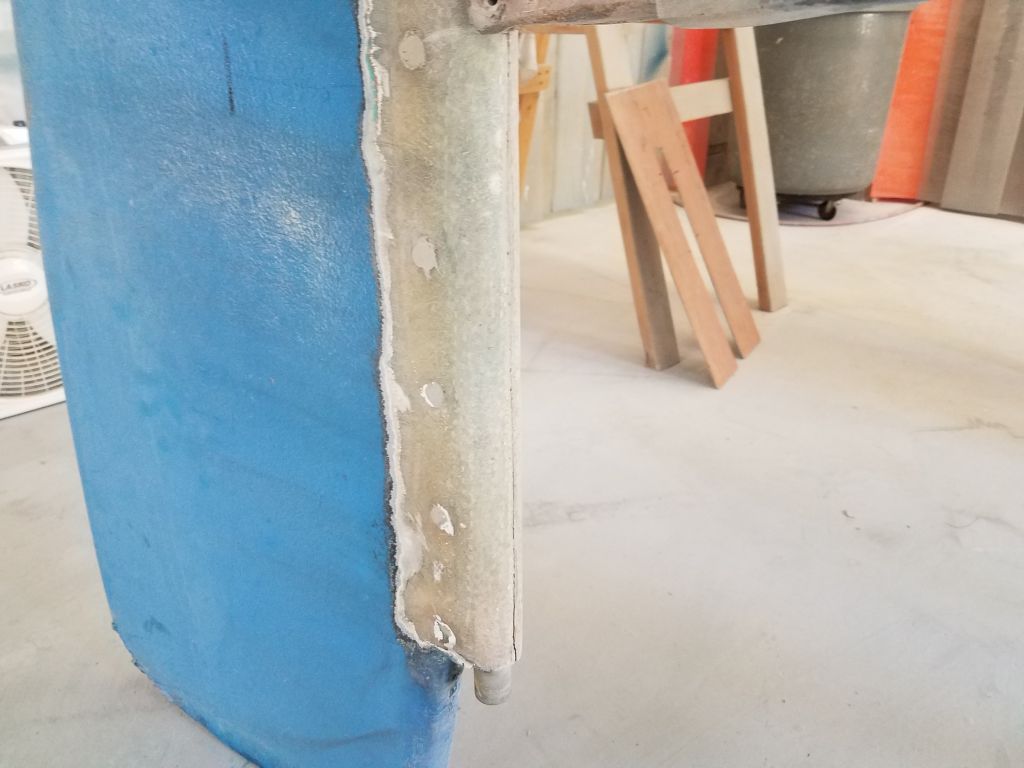


Holding my leading edge template against the rudder according to some reference marks I’d made before grinding, I could see that I’d removed enough material to allow for the rebuilding.
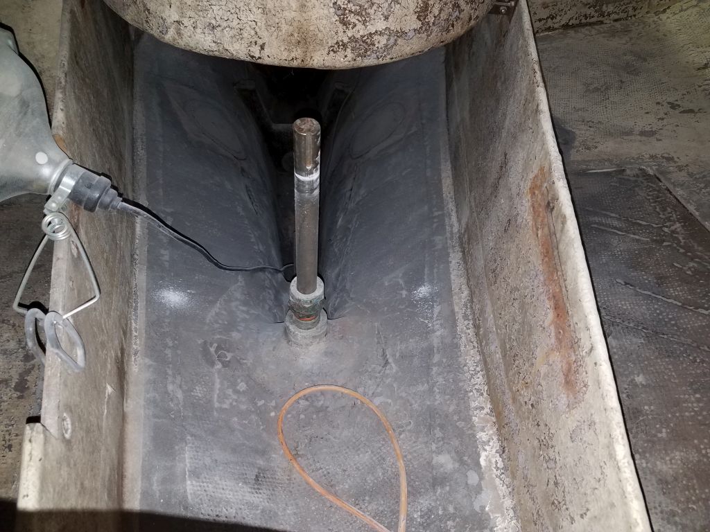
I also sanded the skeg around the edges of the rudder shoe recess, to clean and prepare this area for eventual reinstallation.
Despite these shortfalls, the blade itself, over most of its area, seemed sound enough, and short of starting from scratch I felt that the repair scope was such that I could–and would–proceed with the repair in place, despite the fact that ideally it would have been nice to fully remove the rudder. But I didn’t see the need to spend the time and effort to lift and move the boat in order to drop—and then later reinstall–the rudder given what I’d found so far. I had full access to the top and (later) bottom of the blade, and I could address the leading edge reinforcement in two overlapping sections, since the skeg interfered with part of the rudder even with it dropped as far as possible. But raising the rudder part way after fiberglassing the lower part would allow me the access to the upper section as needed.
Now that I’d cleaned out loose and broken material within the top of the rudder and exposed solid material all around, it was time to build up–in several separate applications to avoid undue heat during curing–the interior of the rudder, now with a solid epoxy mixture of structural components like chopped strand and high-density filler. After two applications during the afternoon, I reached the top of the existing sides of the blade. Additional material to bring the rudder back to its final shape would have to wait till these first stages cured overnight.
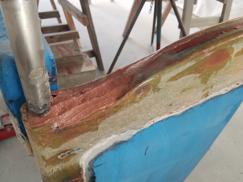
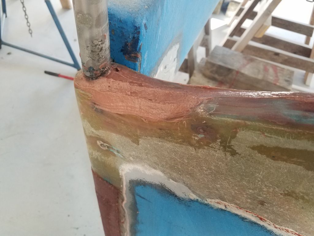

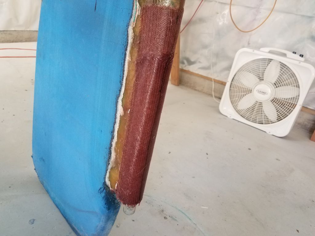
Meanwhile, I got to work on the lower section of the leading edge, beginning with some strengthened epoxy filler in the groove I’d ground out over the crack, then following with two layers of biaxial tabbing set in epoxy. I left room on the second layer so that the second layer from the top section could later overlap and conjoin the two sections accordingly.

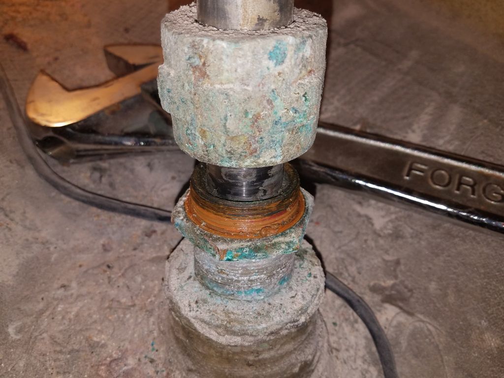
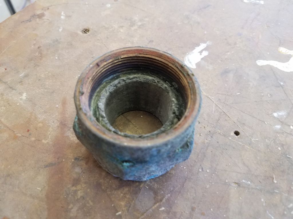
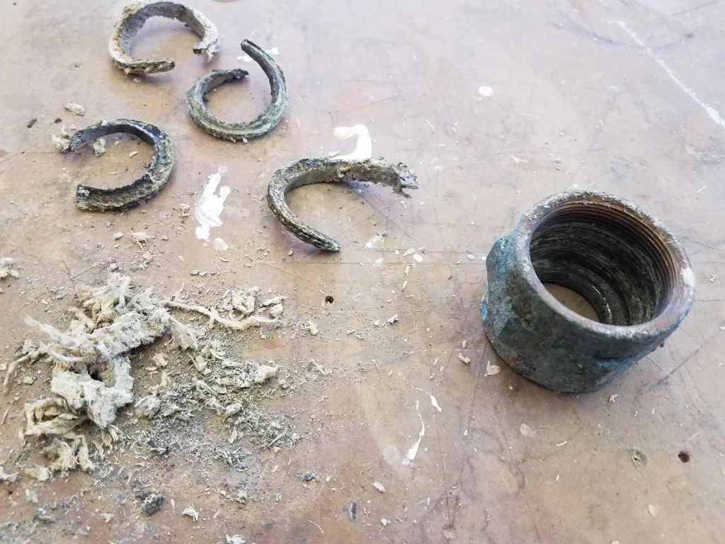
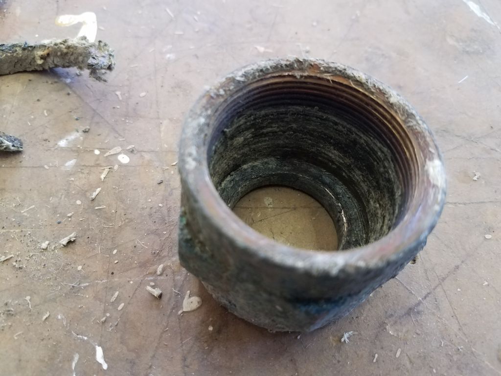
While I had the rudder dropped, I removed the packing nut from inside so I could replace the packing before reinstallation. The old packing (5 rings, though the fifth disintegrated to dust upon removal) was well-worn and overdue for replacement. I’d cleanup the bronze nut and corresponding threads on the rudder tube before installing new packing and reinstalling it once the rudder was done.
Total time billed on this job today: 5.75 hours
0600 Weather Observation: 64°, foggy. Forecast for the day: Fog, then eventual clearing, around 80°