

December 20, 2019
Scupper 207
Friday
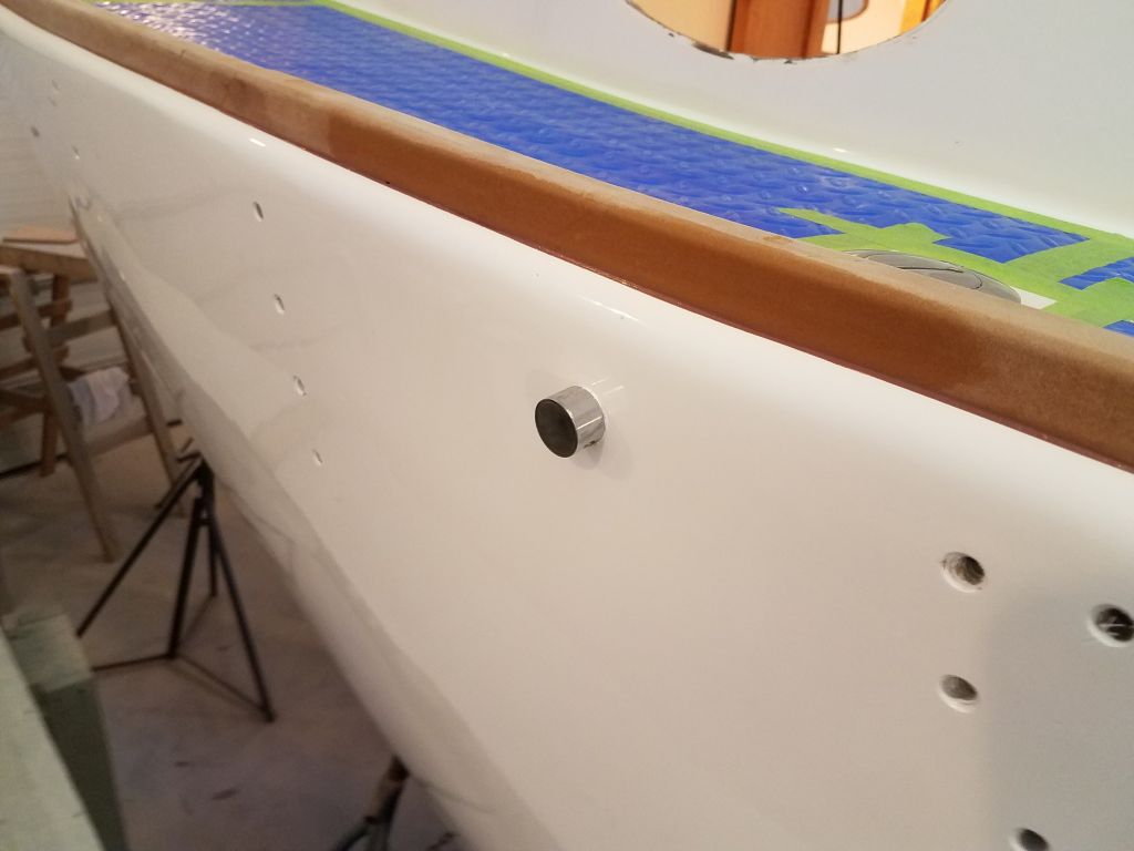
I got started by installing the replacement vent I’d ordered for the water tank. This one was long enough to still work after passing through the thickness of the hull.
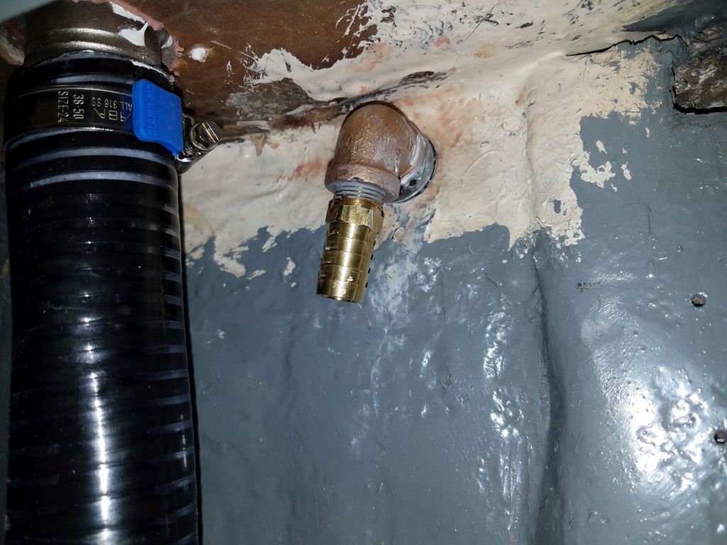
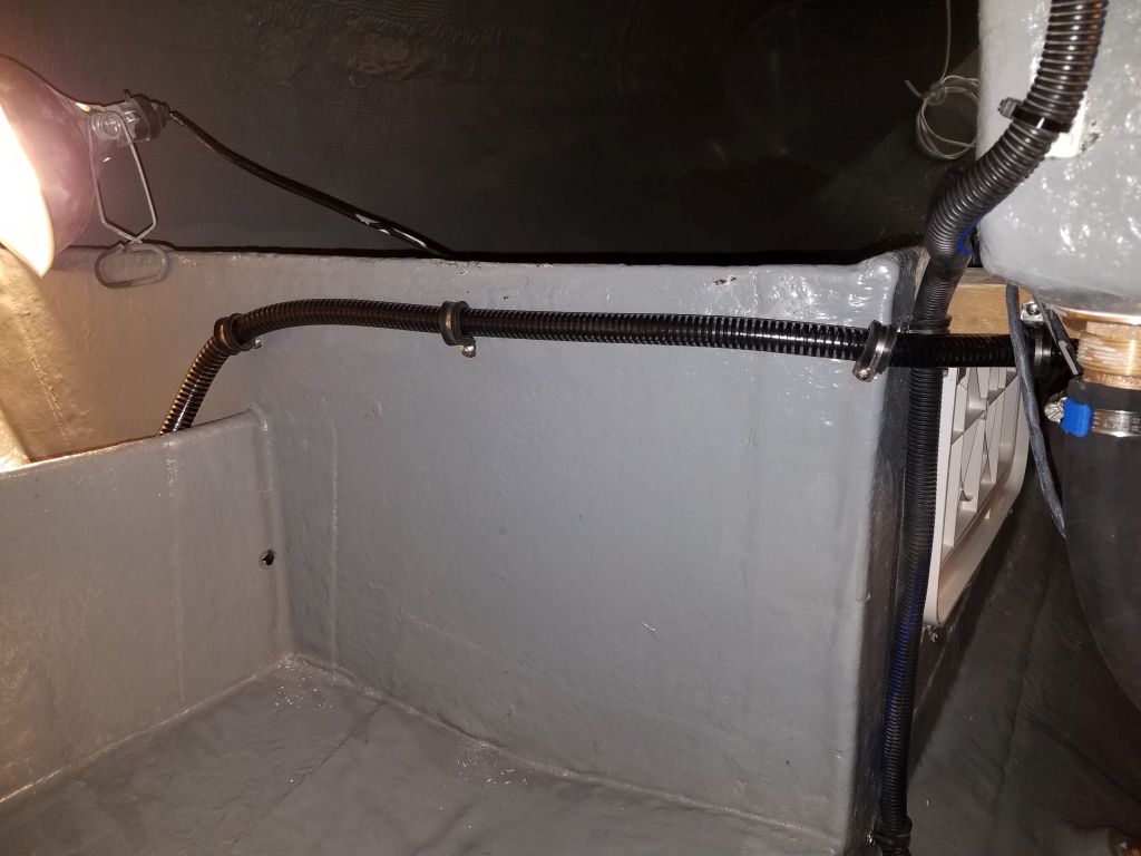
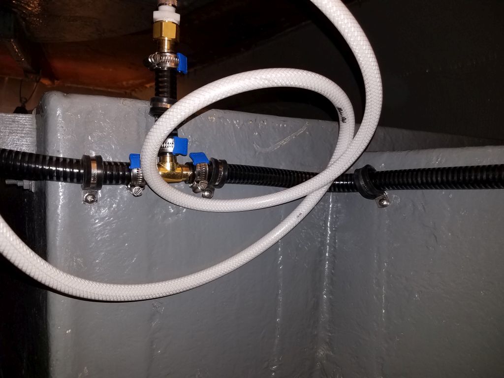
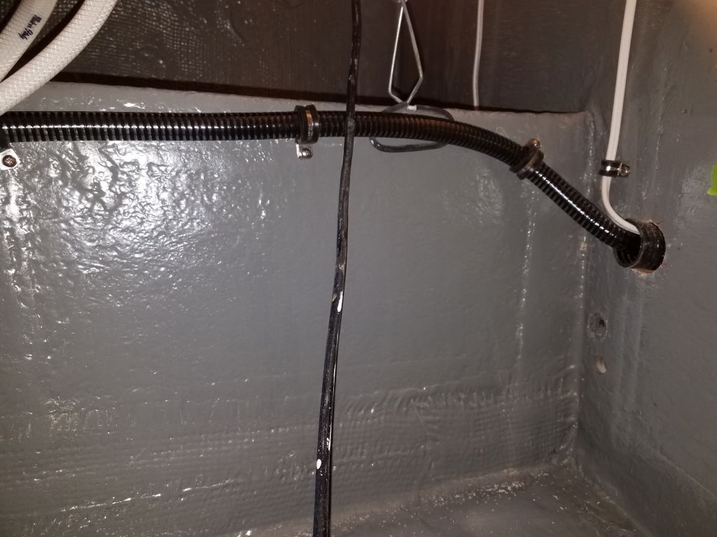
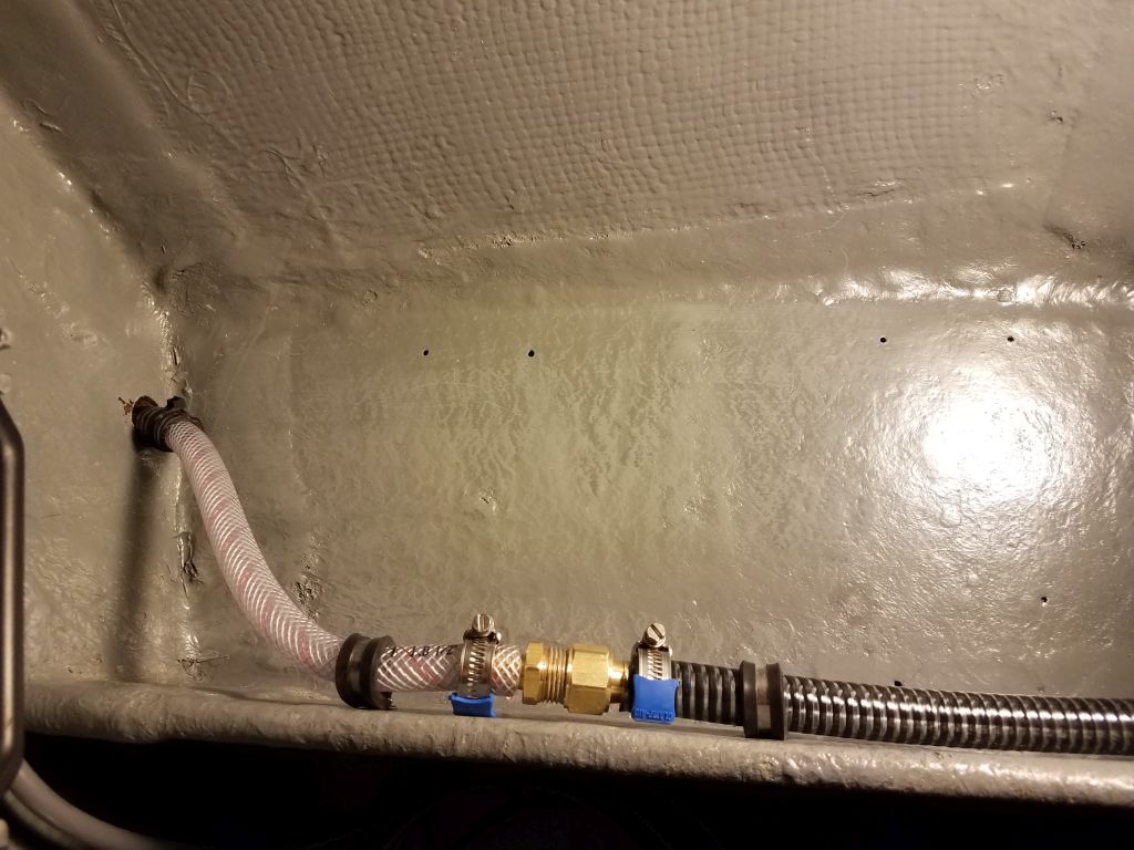
Sticking with the plumbing theme for now, I finished up the water hose run leading from the water pump aft, first through a tee fitting on the port side to accommodate the cockpit shower, then across beneath the cockpit and eventually through the bulkhead into the head area, where the water hose would eventually supply the fresh water flush toilet. Near the end, I reduced the supply line from 5/8″ to 1/2″ to accommodate the nipple on the toilet intake.


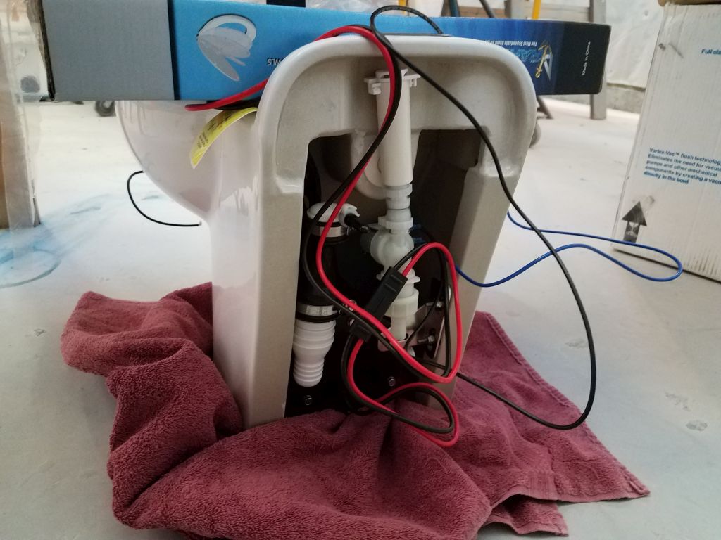
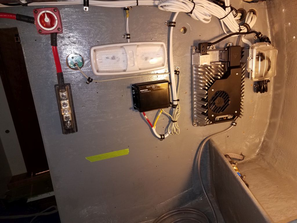
I had expected to install a few more wires from the toilet control box to the head, but found that the wires needed were pre-installed inside the back of the toilet itself, so running them to the control box would happen later on, when I installed the toilet permanently. For now, I didn’t want to do that as I wanted to be sure I finished up as much related (and other) work in and near the head before filling the space with the throne. For now, I put the cover on the control box in the engine room and left it be.
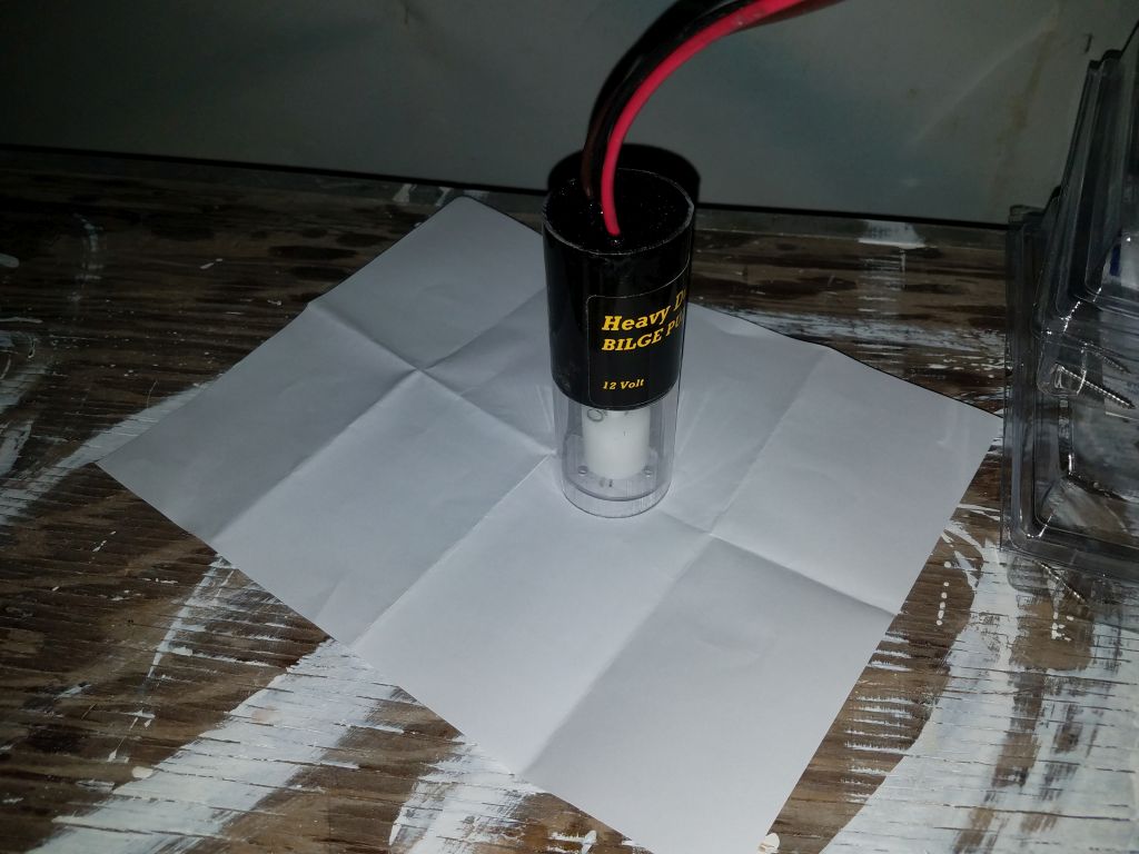
Next on the agenda was the two electric bilge pumps. I planned a diaphragm pump for routine dewatering. This pump, which would be mounted high and dry away from the depths of the bilge, had a smaller flow capacity, but with its diaphragm pumping action and hose to the deepest part of the bilge sump in shaft alley, it would work well to keep the bilge as dry as possible, and wouldn’t allow backflow when the pump stopped.
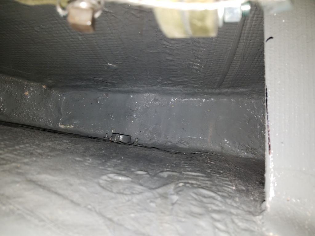
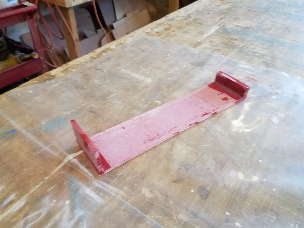
In order to mount an automatic float switch, I needed to build a little platform to secure the switch and be able to lower it into the bilge sump, since this area was mostly inaccessible and there was no way to secure the switch directly to the boat in any event. After measuring the depth required, and allowing for a means of securing the little platform to the engine beds, I built the simple arrangement from prefab fiberglass panels. The switch I chose was a cylindrical fully-enclosed type that hopefully would work consistently without clogging, and was designed to be held in place with a u-shaped bracket; the width of this bracket determined the width of the support I built, but I also included a little base platform on which the pump could rest so it couldn’t slide out of its bracket. I glued up the new bracket with epoxy and left it to cure. I realized later, as I reviewed the photos, that I’d glued the top piece–the smaller chunky piece–on the wrong side. I’d meant the L-shaped bracket to face aft, and for the chunky top to fit over the aft side of the engine platform to accept screws. That said, I thought the bracket would work even turned around, but I’d soon find out.
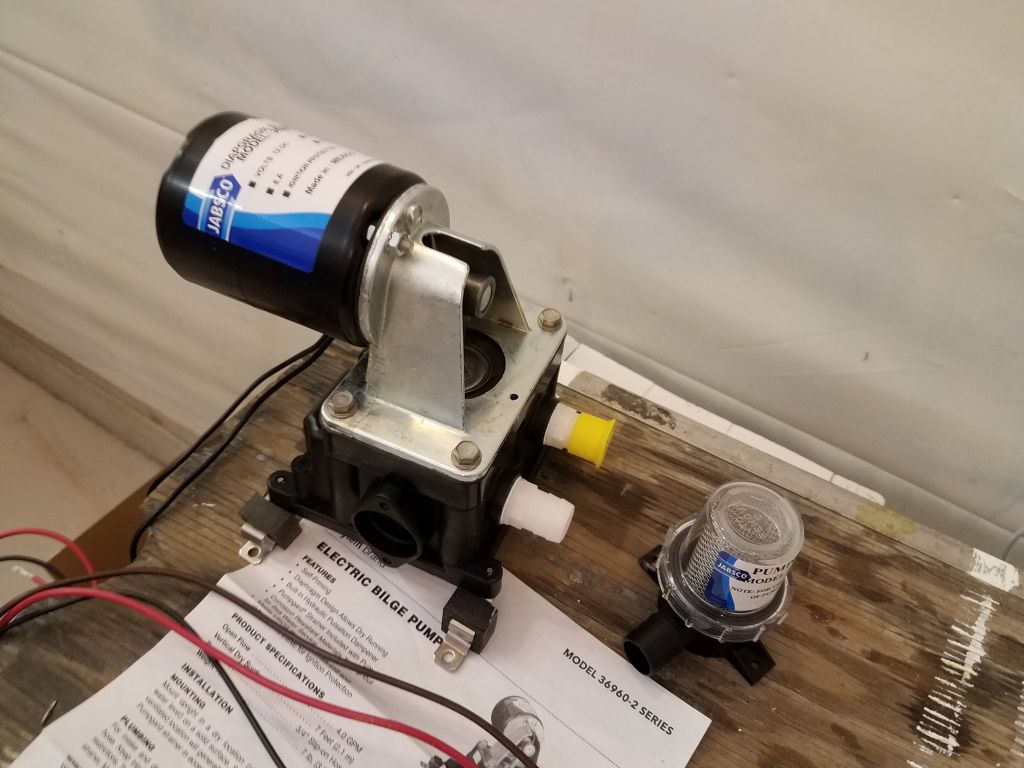
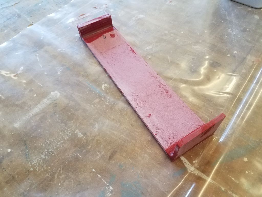
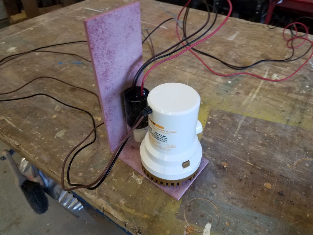
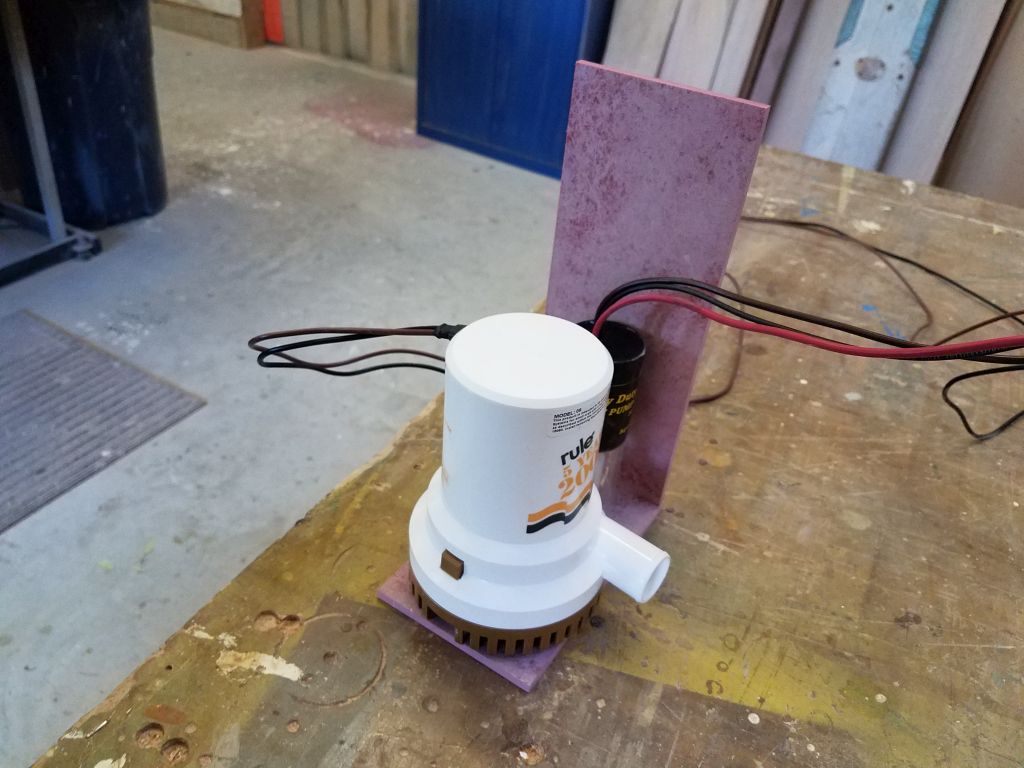
As a backup, and for more potentially significant electric dewatering, I also planned a 2000GPH (0′ head) centrifugal bilge pump to be mounted further forward, in this case in the space accessible through the bilge hatch in the galley. To secure this pump, along with its automatic switch, I built another simple platform, which here I planned to adhere directly to the flat base of the bilge through this locker opening, providing a place to screw in the pump strainer/base and the float switch’s bracket. I made the vertical part of the bracket tall enough to provide a mounting point for the wires, to keep them elevated out of the bilge, and glued up the simple bracket with epoxy. There’d also be, of course, a manual bilge pump to come.
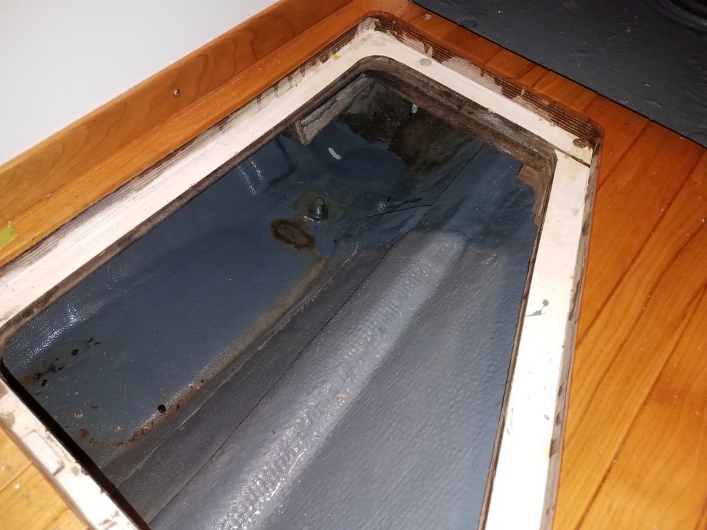

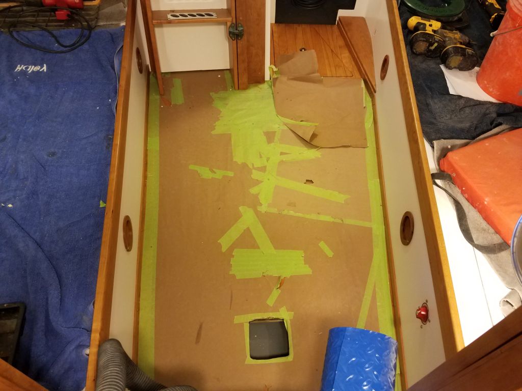
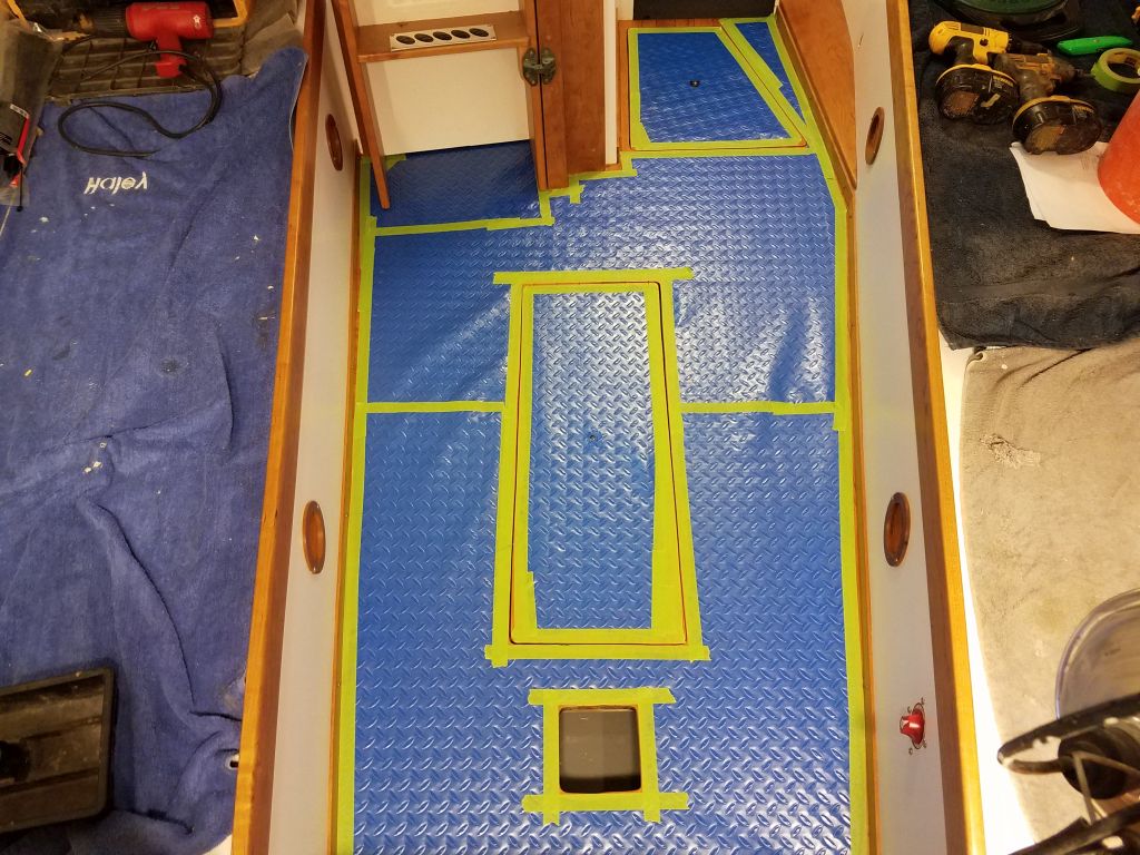
Speaking of bilge access, in order to install the final wiring runs for the mast and some related wiring that would lead from the compression post, I needed to regain access to the forward part of the bilge, which access hatch had been covered for much of the construction with protective paper. In addition, the paper had seen better days, and I’d been patching numerous rips and tears as they occurred. Now, though, I removed the old paper and installed new protective plastic (same as on deck) to the sole, keeping the covering separate over both bilge access hatches so I could come and go as I pleased in the coming days and weeks.
I eased out of the day and the week by looking in some detail at potential anchor windlasses for the boat.
Total time billed on this job today: 6.5 hours
0600 Weather Observation: 4°, clear. Forecast for the day: Sunny, 26°