

December 18, 2019
Scupper 205
Wednesday
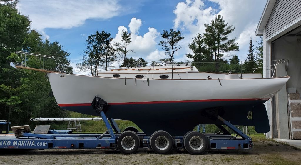
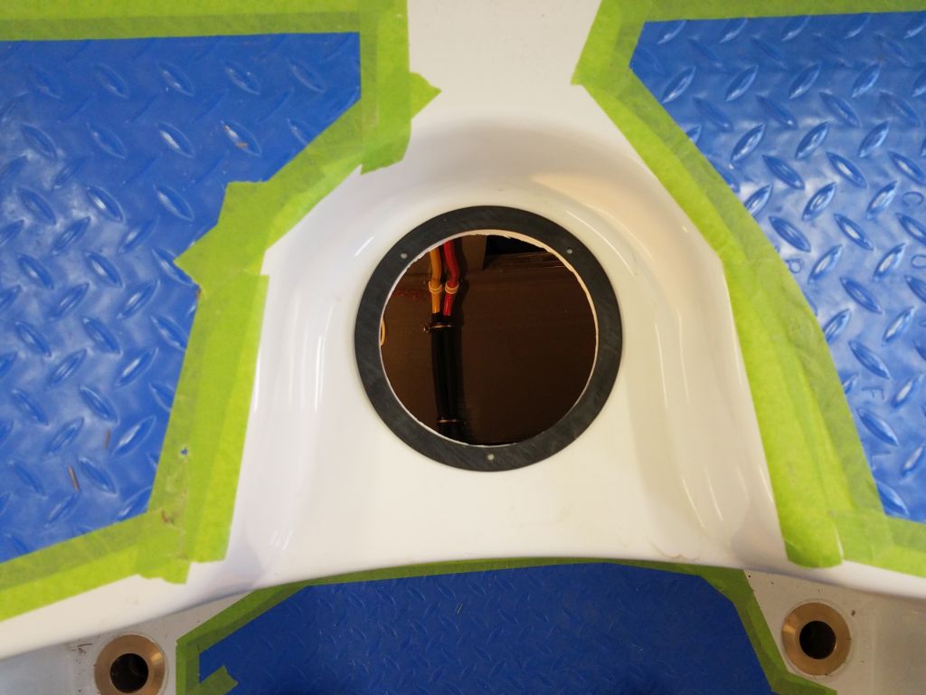
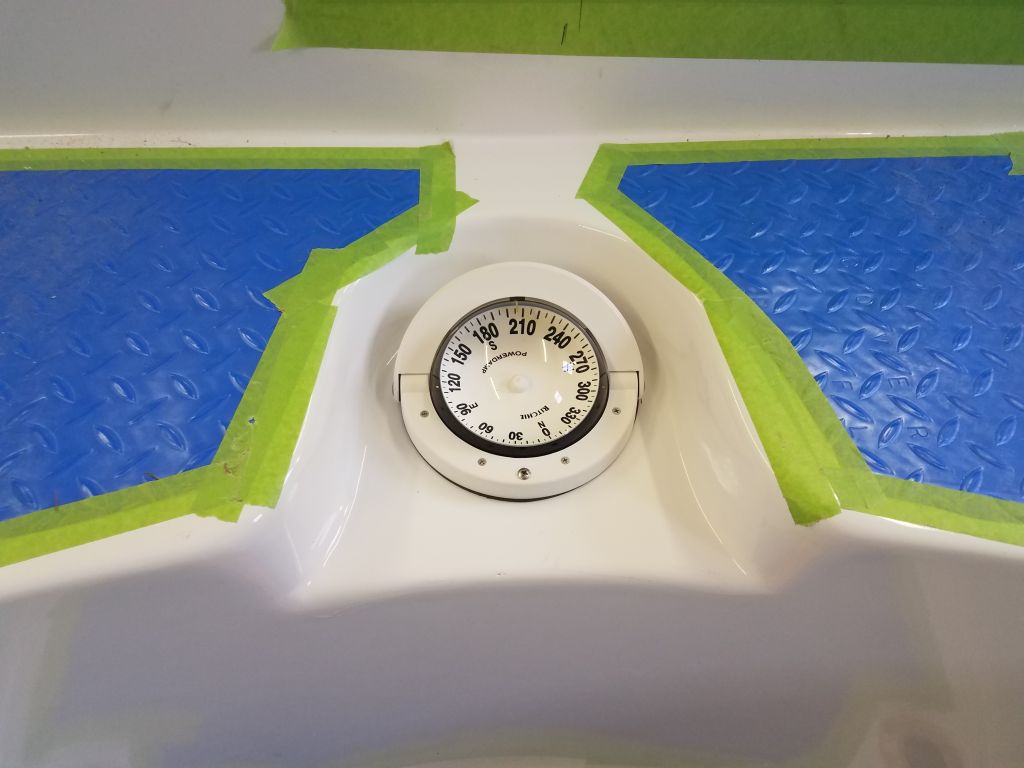
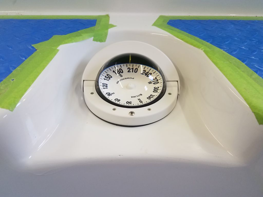
I started the day in the cockpit, where I installed a new compass in the molded recess at the forward end. The large hole I’d drilled there long ago to remove the engine was the perfect size to accommodate the new compass. Installation was straightforward with the supplied gasket and three screws, and afterwards I made up the wiring for the compass light belowdecks.
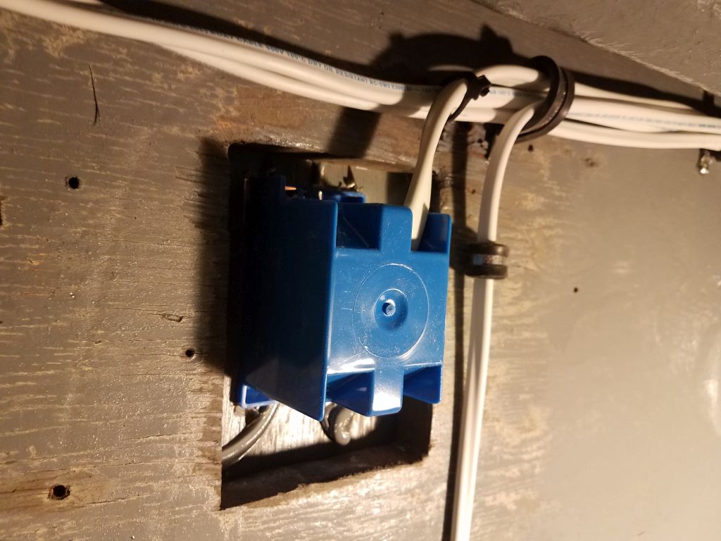
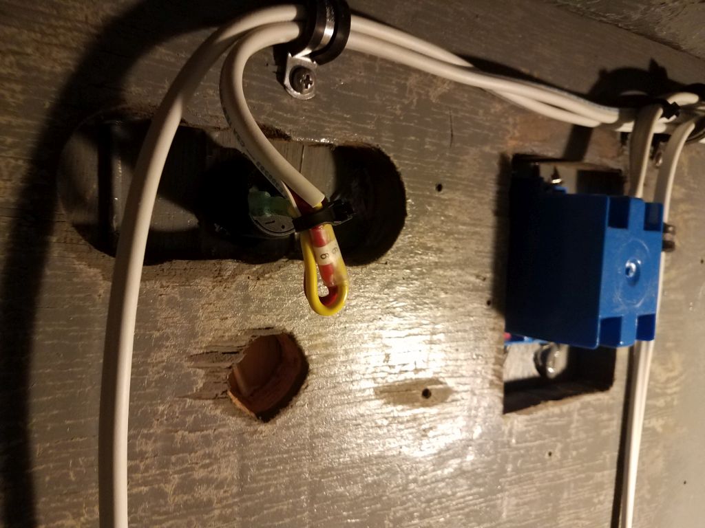
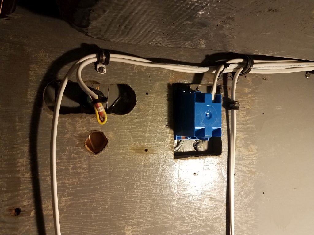
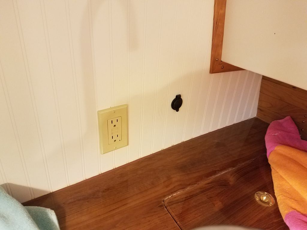
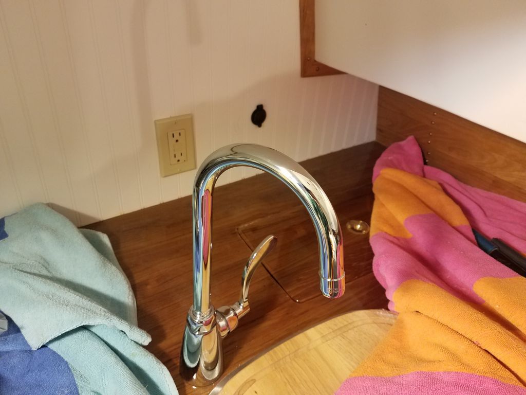
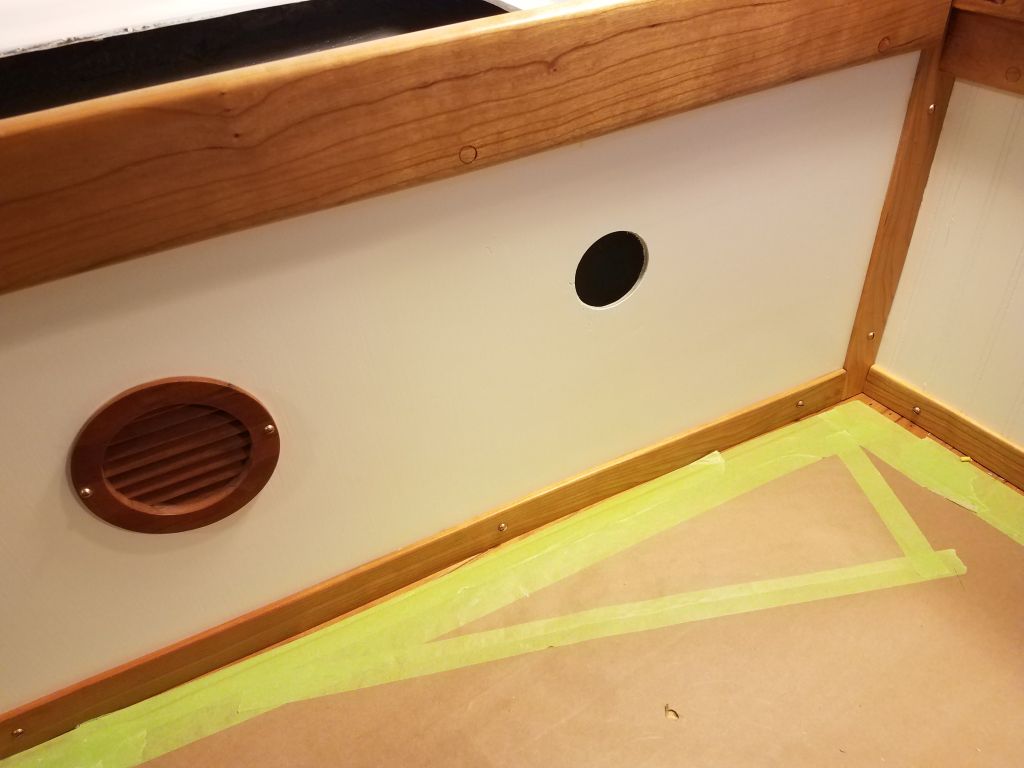
In the galley, I prepared to install both a 110-volt and 12-volt outlet, and cut the required openings for their installation. I installed an outlet box and completed the wiring for the 110-volt outlet, and similarly installed the simple 12-volt socket and completed its wiring as well.

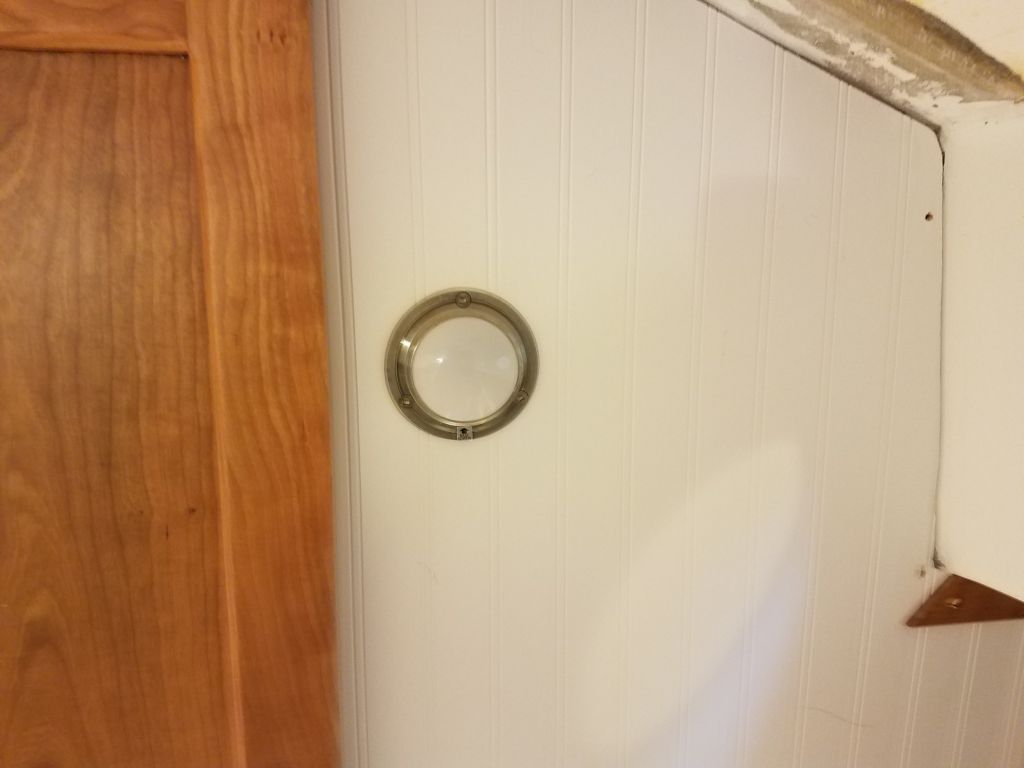
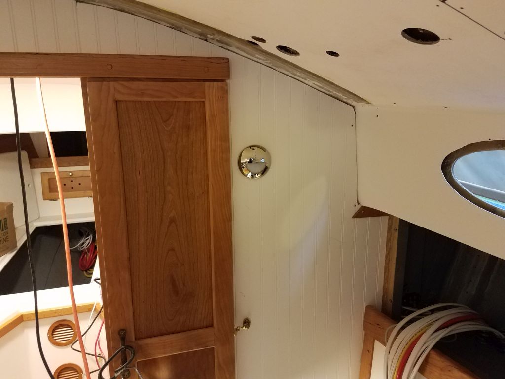
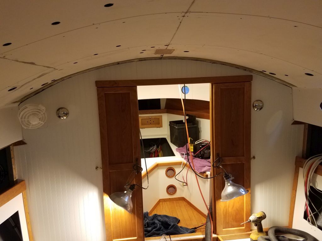
I connected the newly-arrived transducer extension cable and led it the short distance up to the area where the display would soon be installed (no pictures). Then, I moved into the main cabin, where I decided to install the starboard bulkhead light fixture. Because the doorway to the forward cabin was off-center to starboard, I mounted the light at the same height and as close to the same transverse position as on the port side, while accommodating the open doorway. For now, I just led the wires through the bulkhead for later attention.

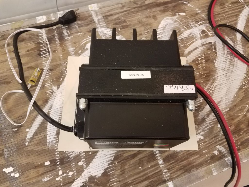
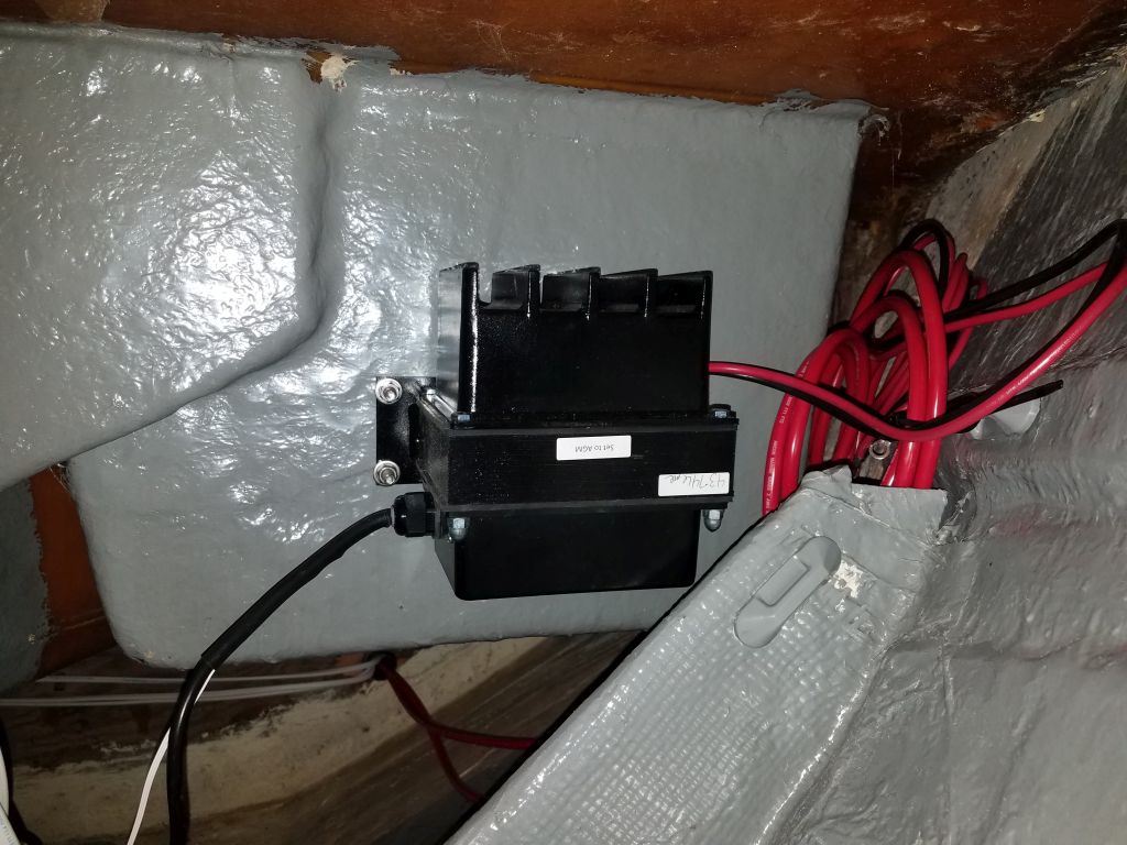
While I’d been working below the v-berth over the past couple days, I’d pre-selected the location for the charger for the house battery bank, and now I went ahead with its physical installation. The location I chose was on the port side, on the forward face of the port storage locker below the berth. There was ample room on that surface, plus the bolts to secure the charger would be out of sight inside the locker.
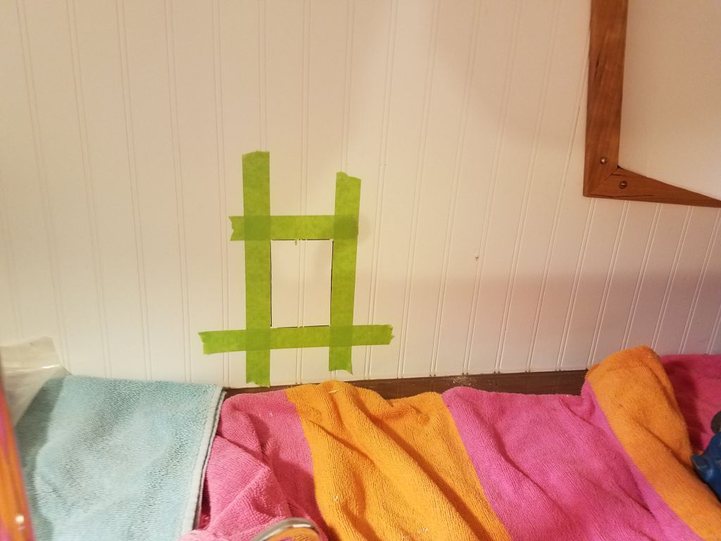
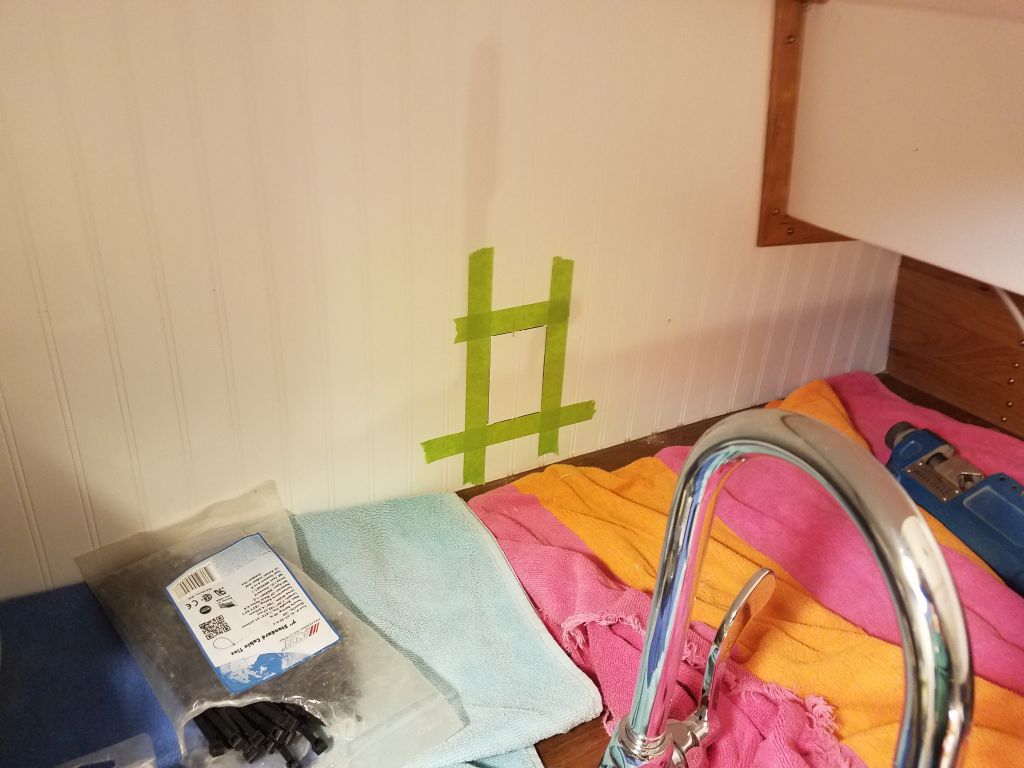
The charger was extremely heavy, and to ease installation I made a simple template of the base design and the overall shape of the charger to help me position the holes.
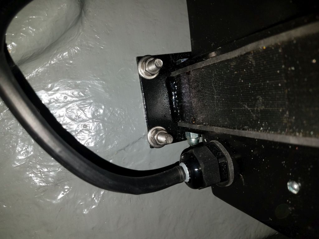
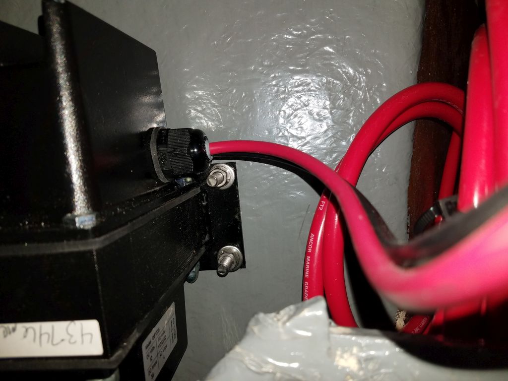
In the boat, I collected all the tools I’d need and got set up in the v-berth, then drilled the mounting holes according to my template. Then, with some difficulty thanks to the weight of the charger, I secured it to the bulkhead with four 5/16″ bolts, incorporating larger washers on the inside of the locker. I positioned the charger so that its short power cord would be within reach of the outlet box I planned to install (and had arranged accordingly during earlier “thought sessions” while working elsewhere up there), and its included battery cables were of ample length to reach the battery box once installed.
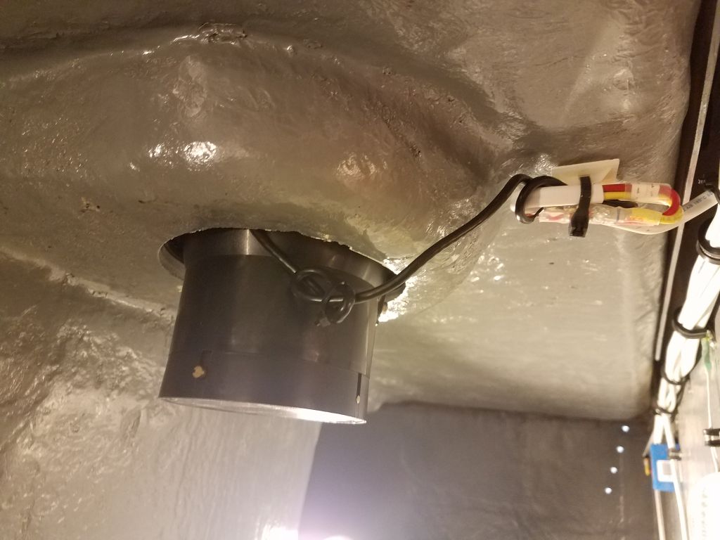
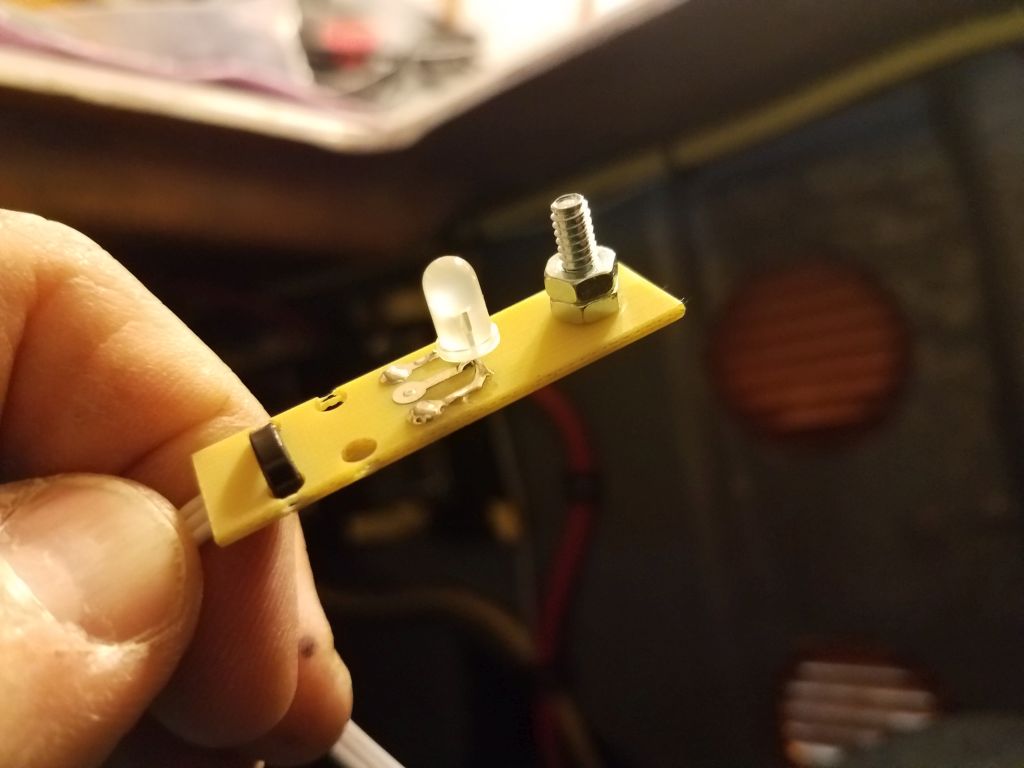
Appended to the power cord was a short length of wire with a rudimentary “remote” indicator light attached. This cable was only 18″ or 24″ in length, vastly limiting its remote-installation capabilities, and the entire thing was somehow inelegant and poorly planned, with an ugly stud required for mounting and only a basic lamp as an indicator, all crudely attached to the most minimal circuit board imaginable, and with a thoughtlessly-short length of cable to allow mounting options. The indicator lamp built into the charger was not accessible for regular or even sporadic viewing in the charger’s location.
This meant the only feasible mounting location, when considering the cable length and the other realities of the available space (including, not unimportantly, access from within and the thickness of the various surfaces), was the forward section of the v-berth cutout, where the fiberglass panel was about 3/16″ thick and could potentially accommodate the light. As of this writing, installation details were under review. The good news is that I installed (or am technically still installing) a nice battery monitor for the house bank, so this monitor would more than obviate whatever minimal information the charger indicator light might provide.
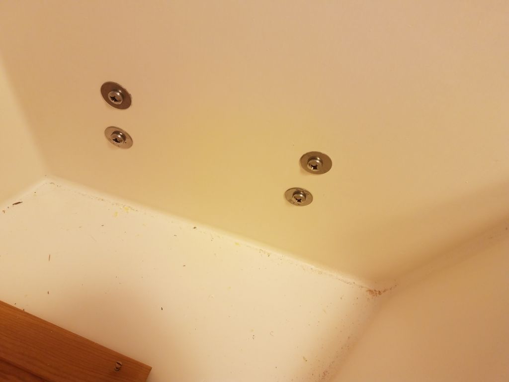
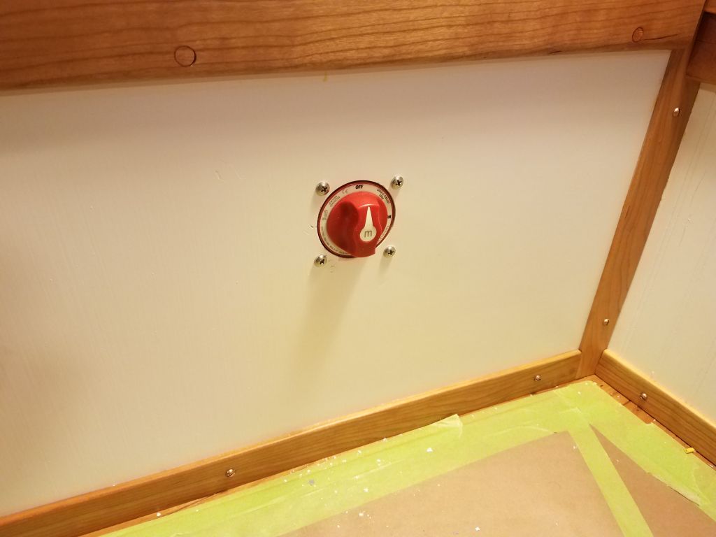
Next, I installed the house battery switch, choosing a location in the port settee base. After drilling the required 2-5/16″ hole, I flush-mounted the switch from behind, making up the cable ends and securing them as required to the switch before installing the back protective cover and installing the whole switch with four bolts, which I’d return to later to remove the excess length.

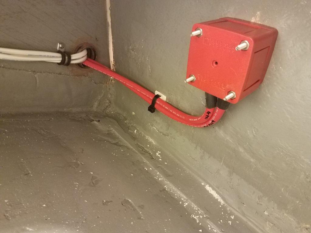
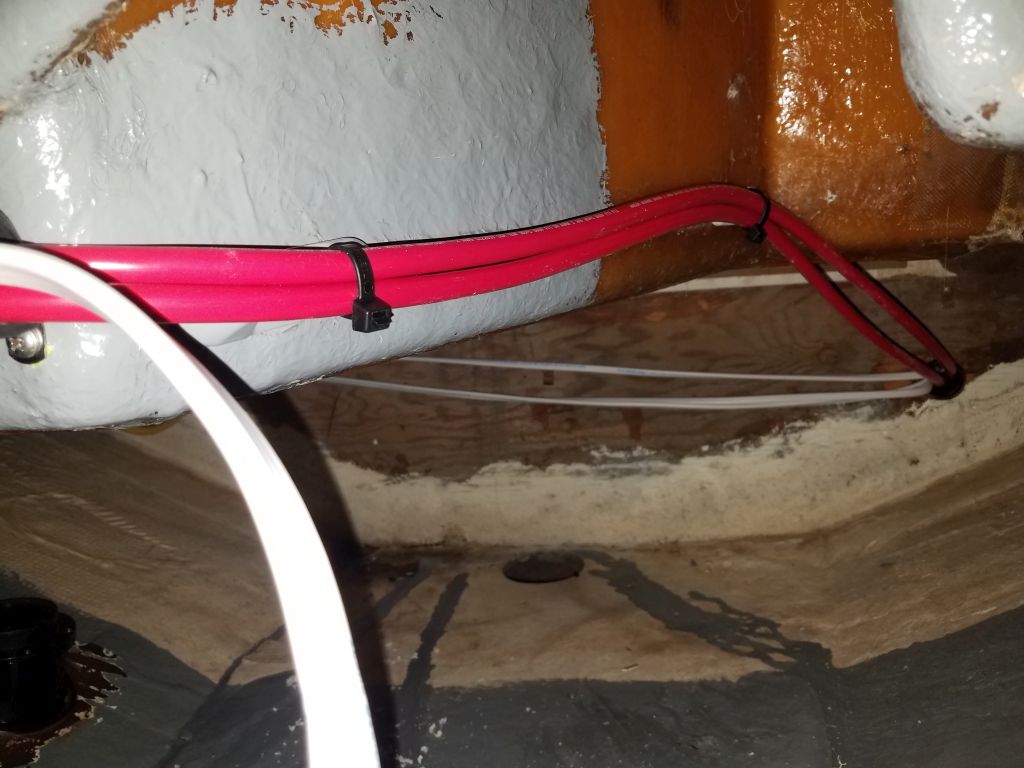
I pulled the excess cable forward and secured it below the v-berth unit, and finalized the connection for the “downstream” cable leading from the switch to the positive distribution buss. I left the other cable unterminated for now, as it would eventually connect to the battery positive but I didn’t yet know how long to make the cable.
Total time billed on this job today: 8 hours
0600 Weather Observation: 25°, cloudy. Forecast for the day: Snow showers, cloudy, 31°