

June 21, 2019
Scupper 161
Friday
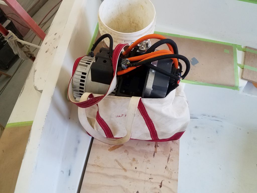
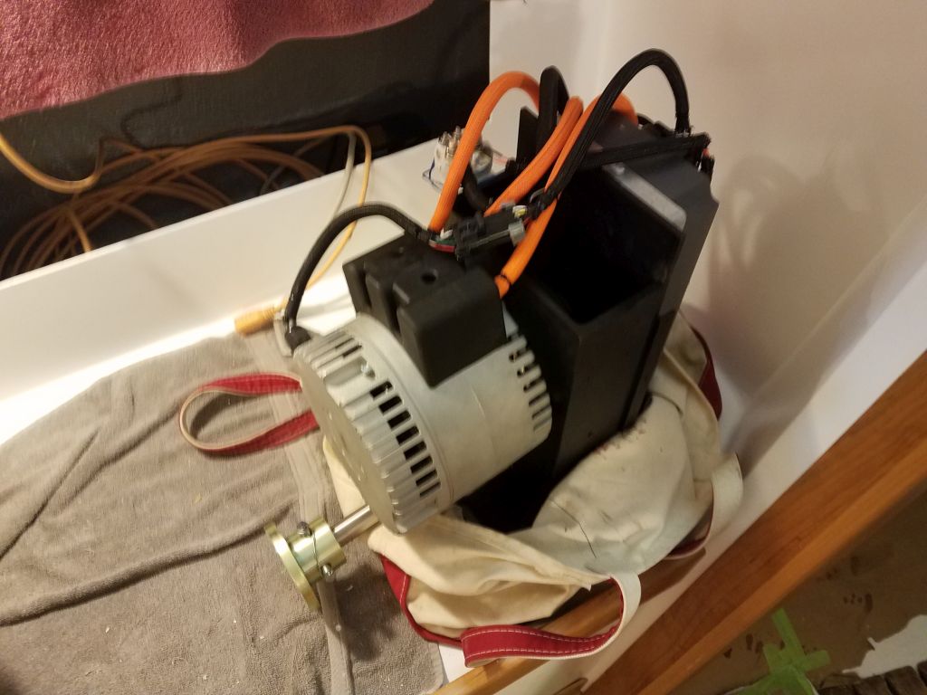
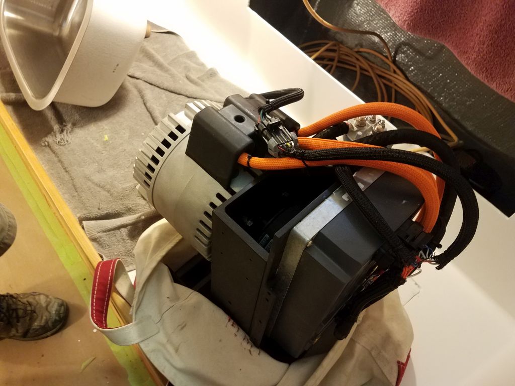
One advantage of an electric propulsion motor from an installer’s point of view is that the assembly is smaller and lighter than a diesel engine, but that said the motor was still quite heavy and rather ungainly to maneuver. To get the motor up and into the boat for the beginnings of installation, I put it into a large tote bag, which made it relatively easy to get up the ladder, into the cockpit, then down safely into the cabin, and eventually into the engine room.
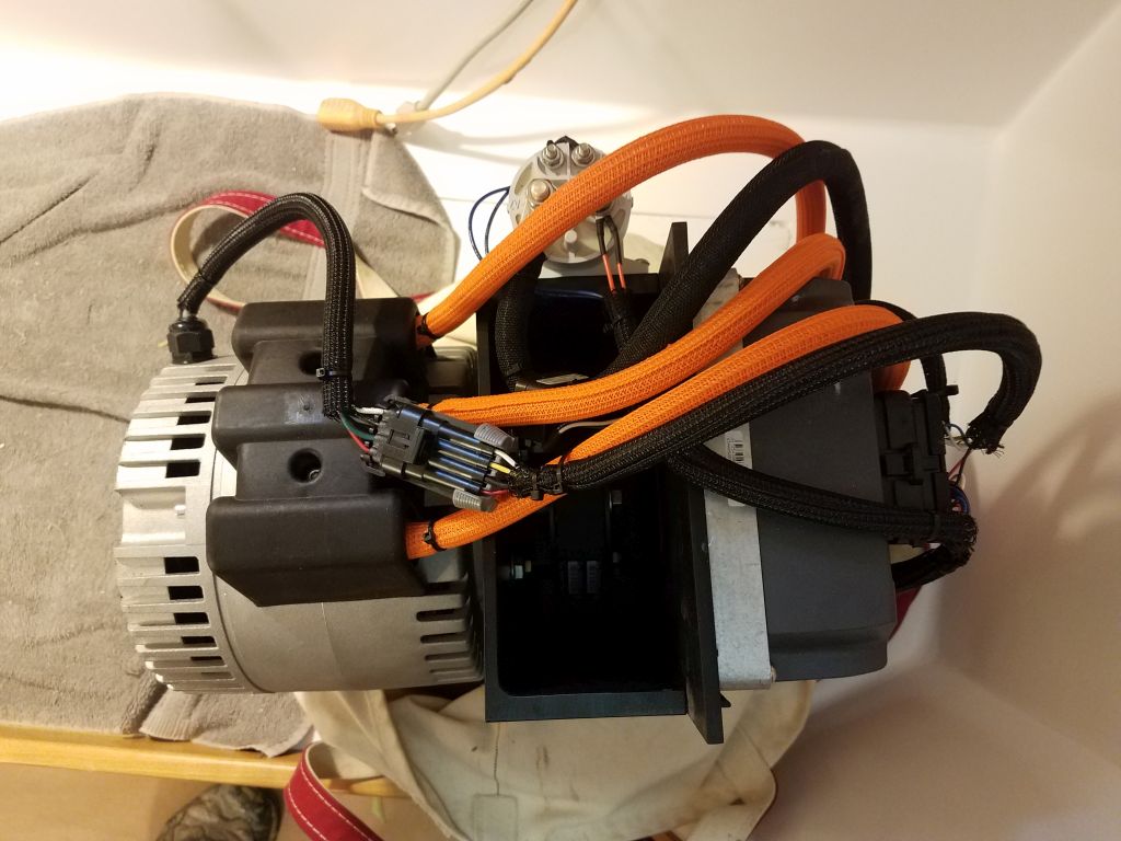
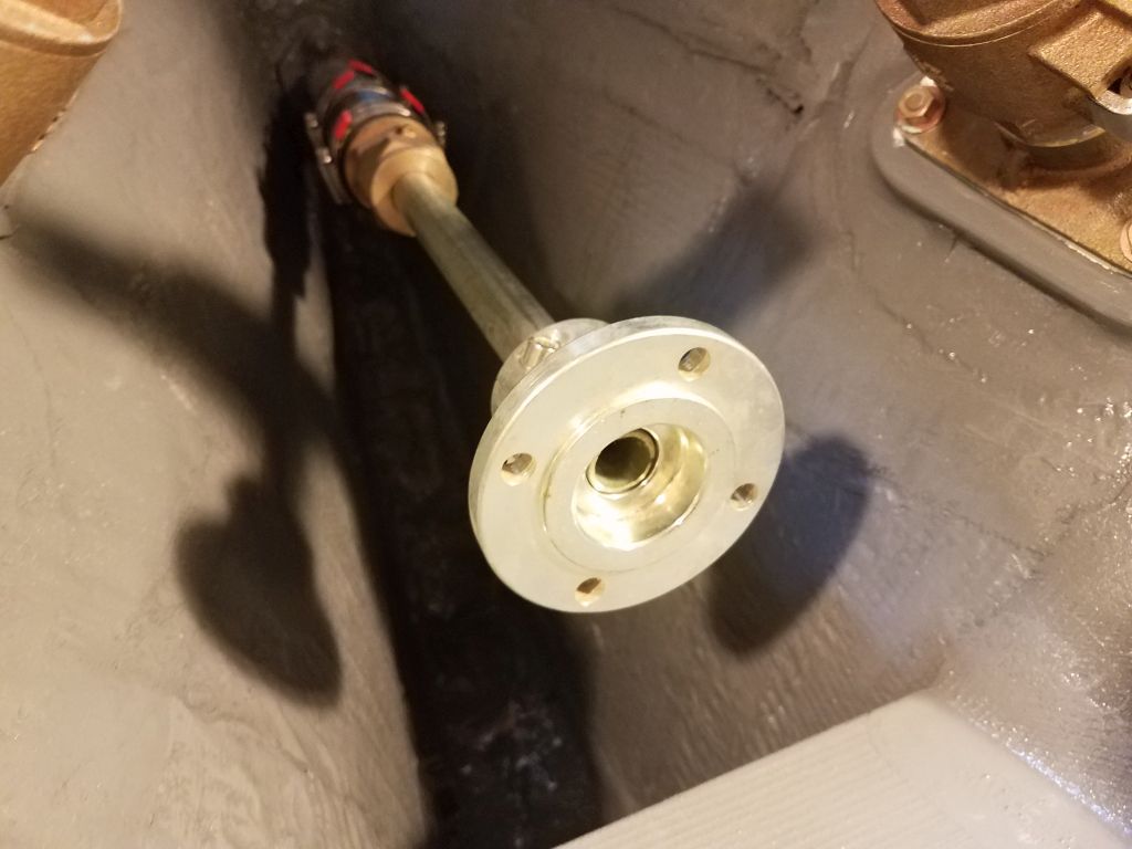
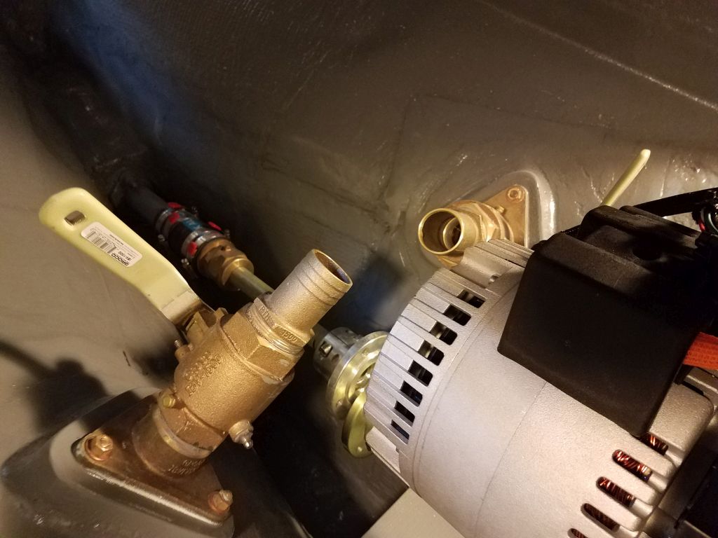
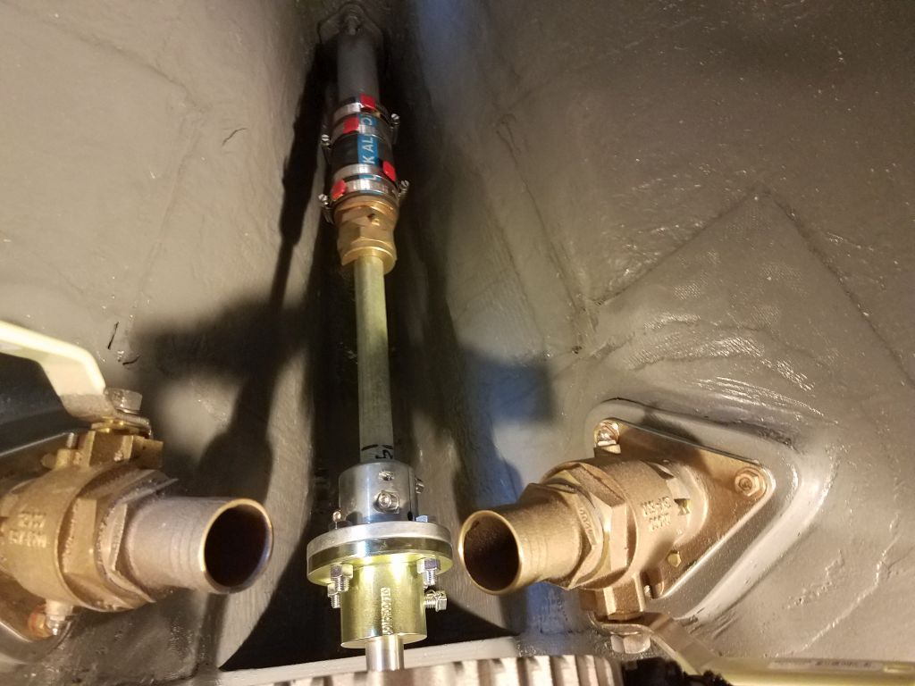
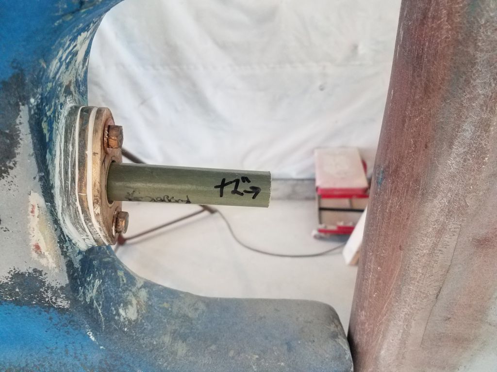
My immediate goal was to finalize the position of the motor (I might slip and call it an engine) in the engine space, and to align it properly with the stern tube and a stand-in propeller shaft. The configuration of the aperture and rudder prohibited installation of the shaft from outside, so before I could permanently install the motor I’d have to measure for, order, and obtain the new propeller shaft. The output shaft from the electric motor featured a typical coupling on the end, ready for easy mating with a standard shaft coupling, one of which I had on hand. Using a length of 1″ fiberglass tube as a propeller shaft, I installed the coupling and inserted the shaft from inside the stern tube.
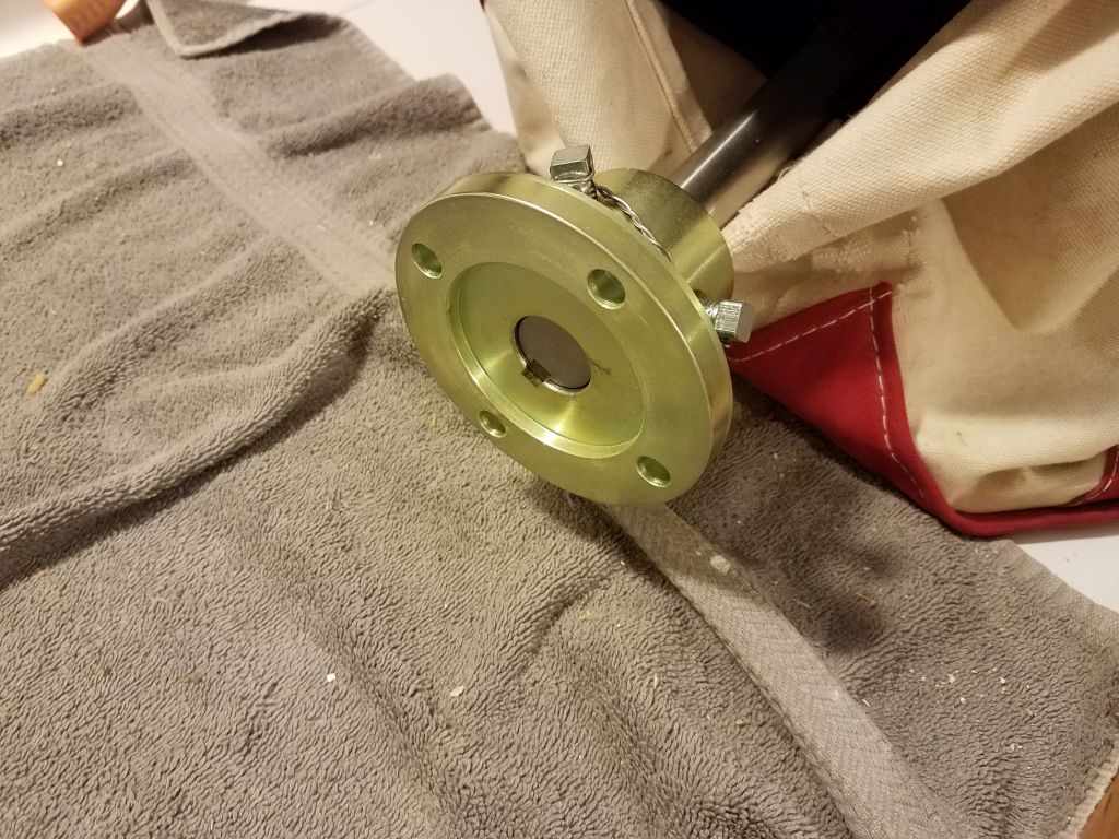
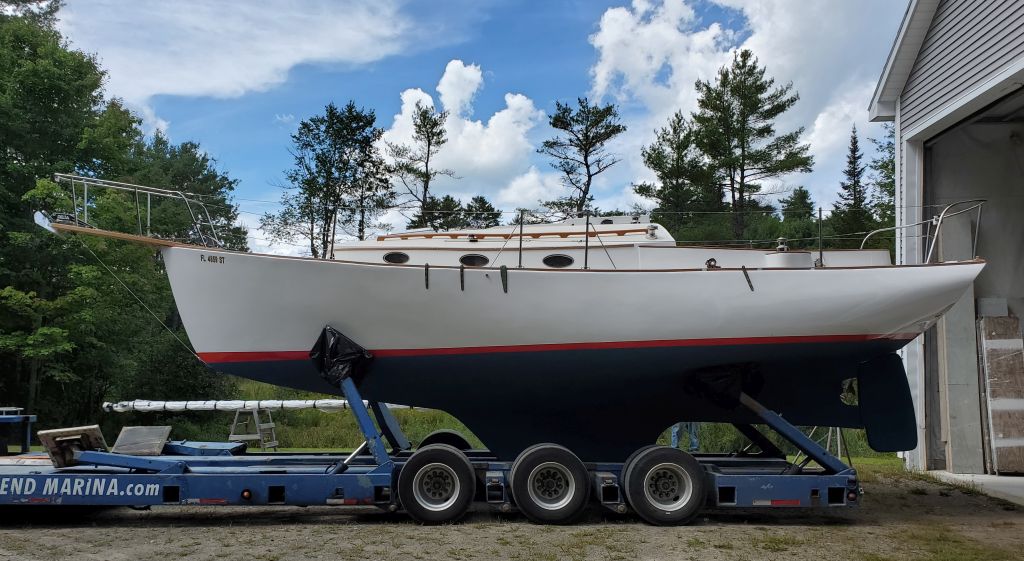
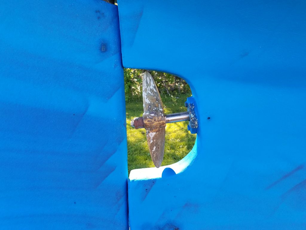
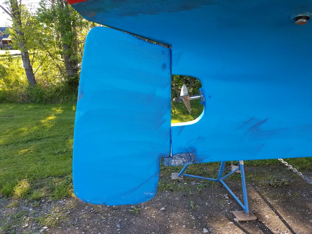
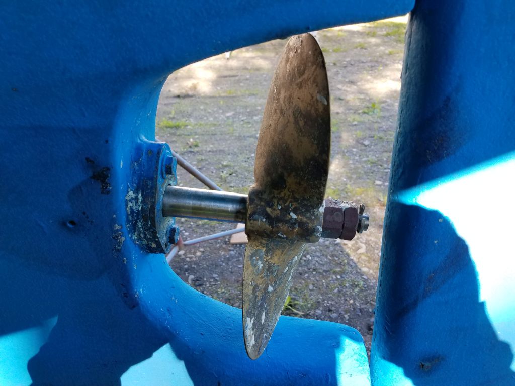
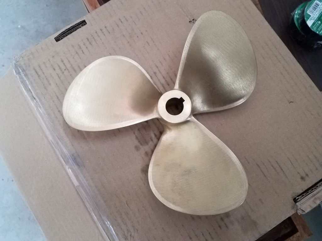
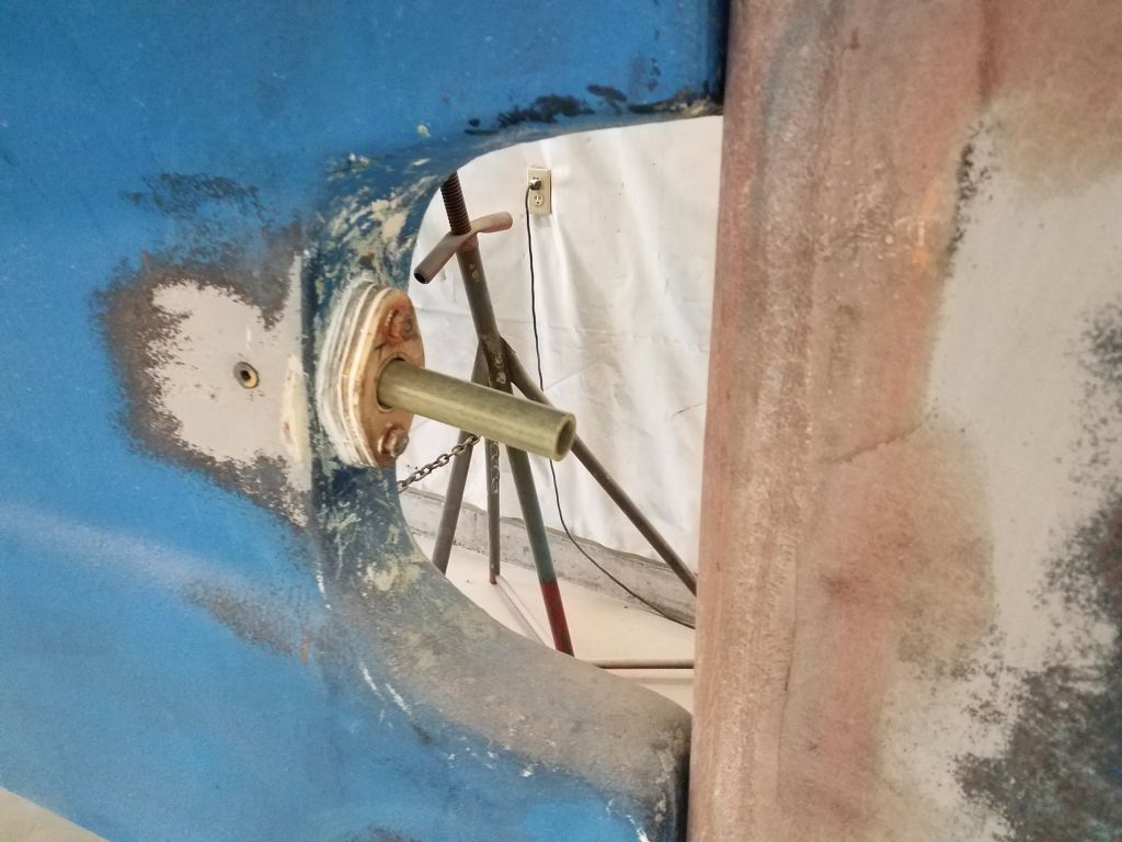
The small aperture size, and again the interference from the rudder, also meant that I planned to install the new propeller over the shaft before final engine installation, and to that end I’d already purchased the 10×8 3-blade propeller required for and specified by the electric motor manufacturer for this boat and her undersized aperture. The first photos here, dating to June 2017, show the original propeller and the aperture setup; the final photo shows the new propeller.
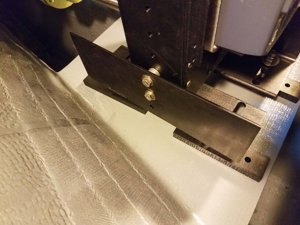
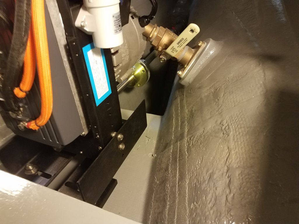
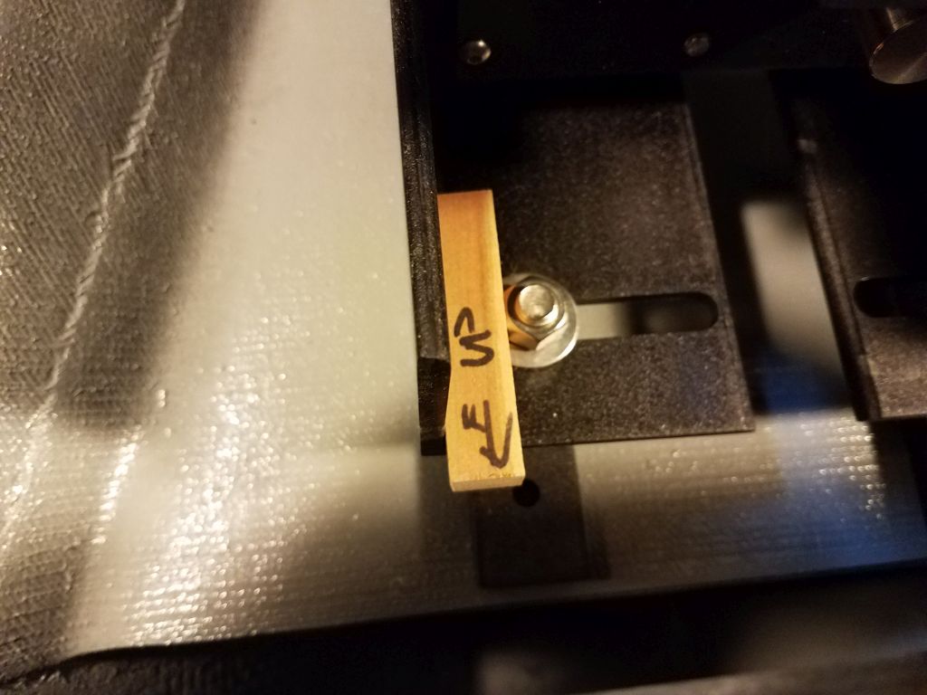
With the shaft now in place from inside, I moved the electric motor into position on the platform I’d built earlier (using dimensions from the motor manufacturer to determine its height vis-a-vis the existing stern tube). The L-shaped mounting brackets were already in place on the motor, but I’d not yet installed the actual adjustable feet, so, not unexpectedly, the motor sat about 2″ too low.
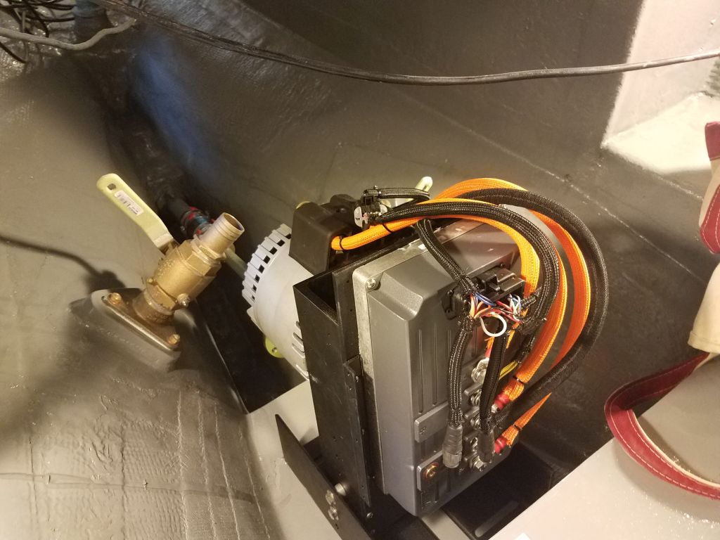
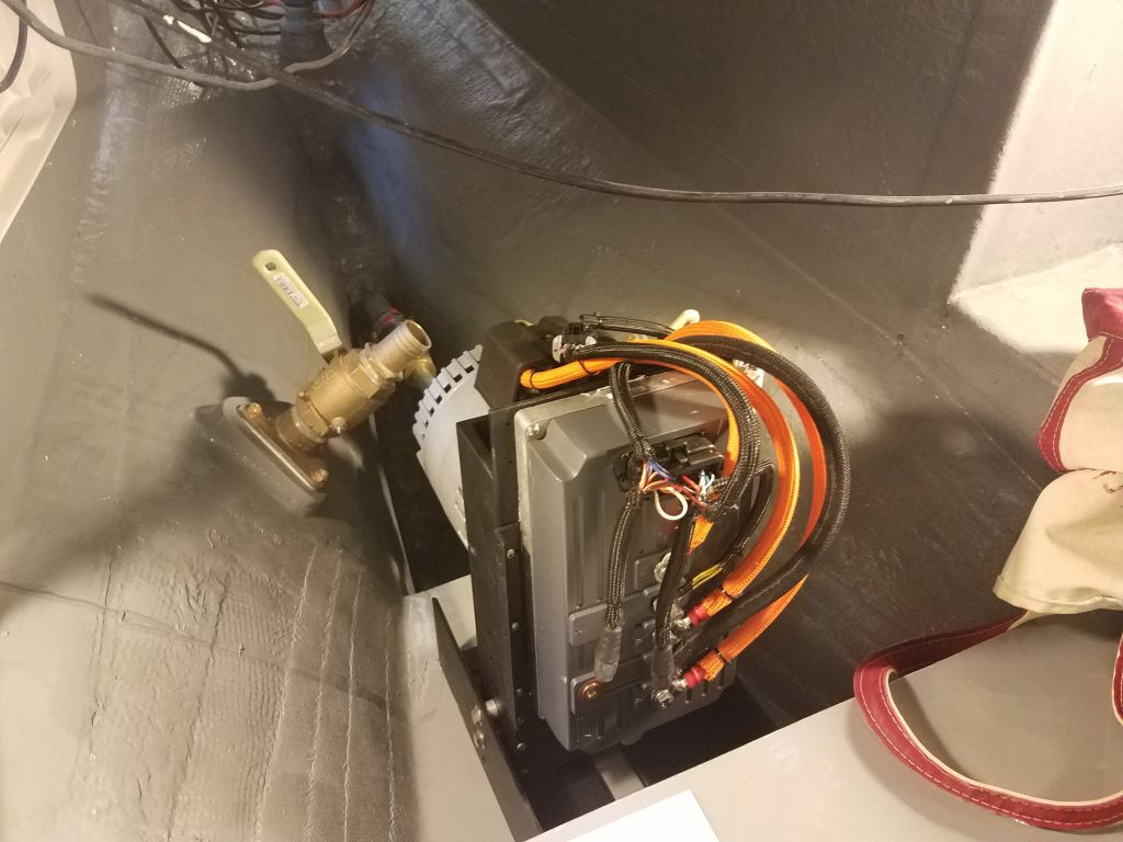

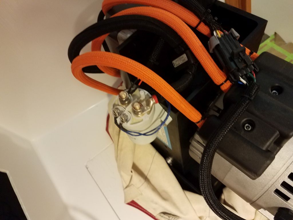
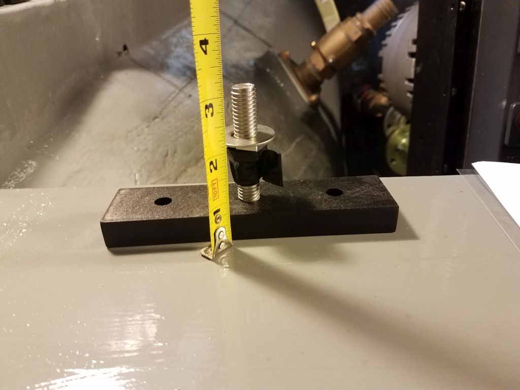
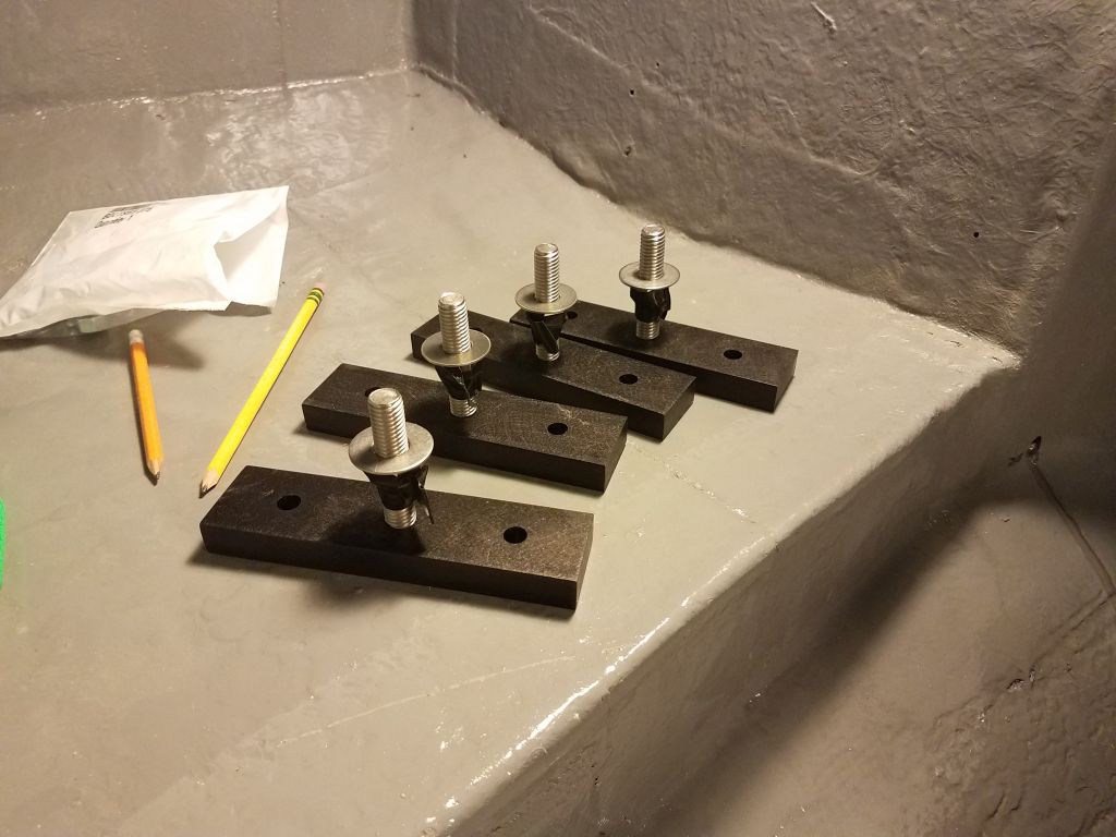
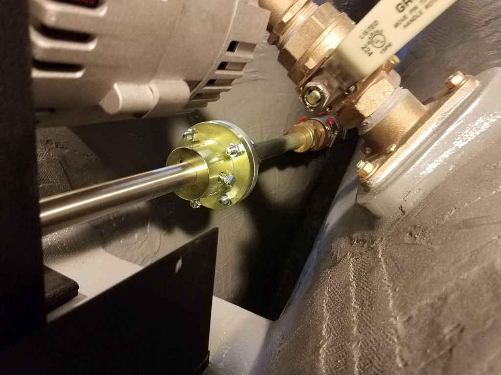
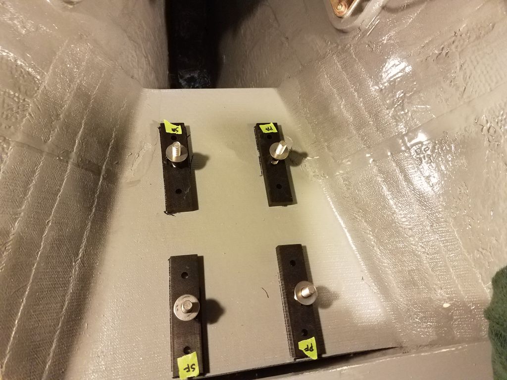
I set up the four adjustable mounts with nuts and washers at 2″ above the base, then installed these in the slotted holes on the mounting brackets. This raised the motor, and its output shaft coupling, to virtually the perfect height and alignment with the propeller shaft coupling.
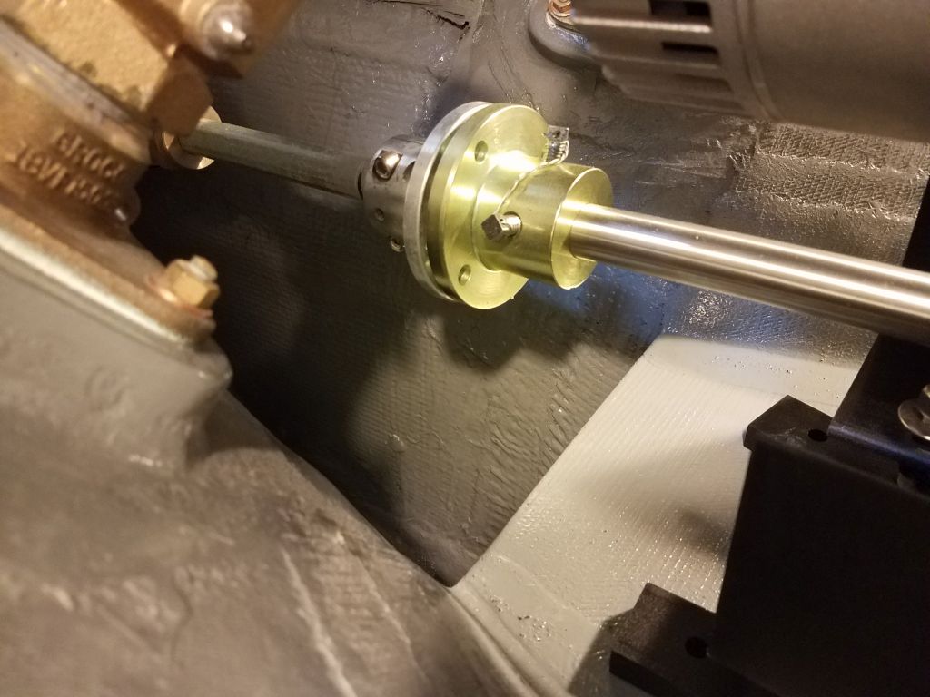

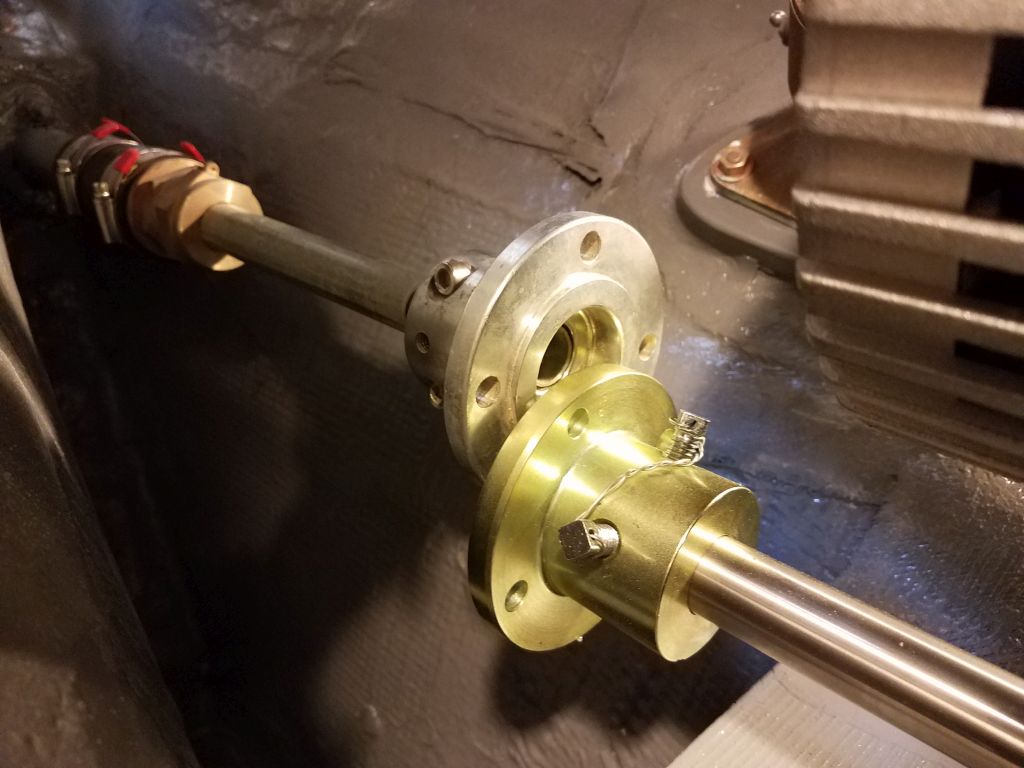
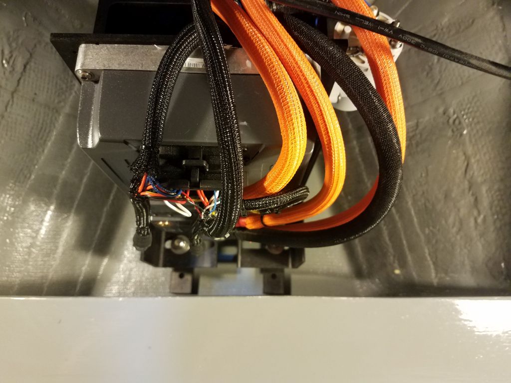
After minor adjustments to the motor’s position on the platform as I optimized its longitudinal position and fine-tuned the couplings’ positions, I secured the two couplings together temporarily.

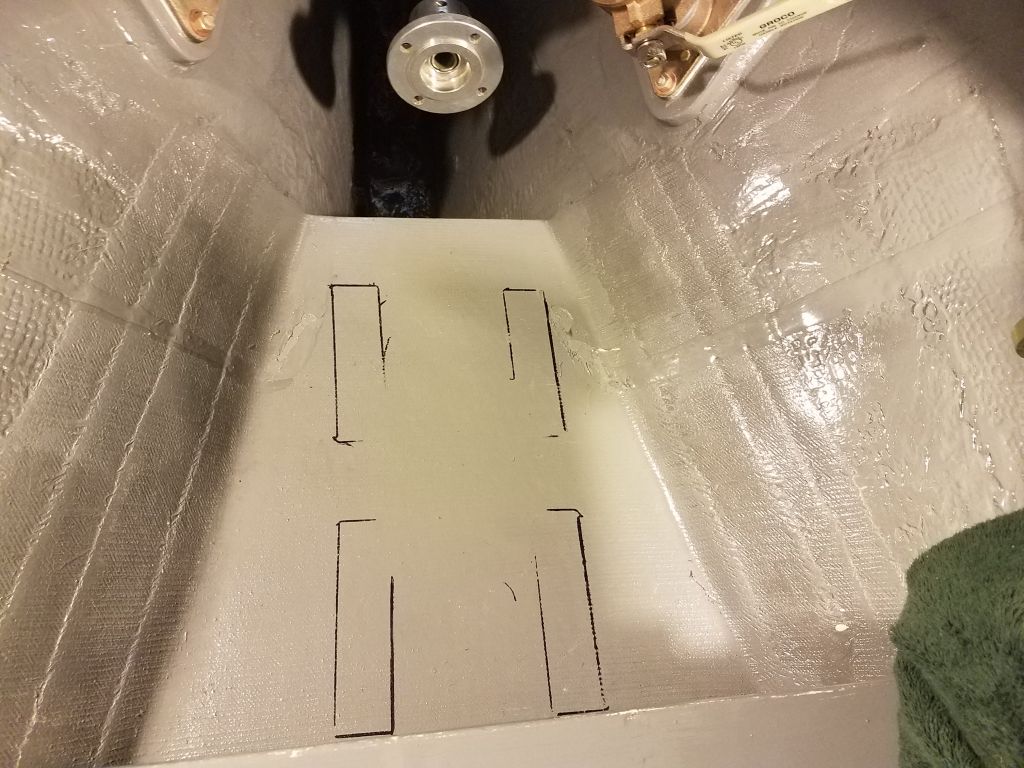
With the engine’s position now set, I finalized the positions of the four adjustable mounts on the platform. With transverse slotted holes in the engine brackets, I chose to keep the mounting studs in just a bit (3/4″) from the outermost reaches of the slots to allow some room for adjustment later if needed, and used a small spacer block to set all four locations in this way. Then, I marked the engine platform around each mount so I could locate and permanently install them momentarily.


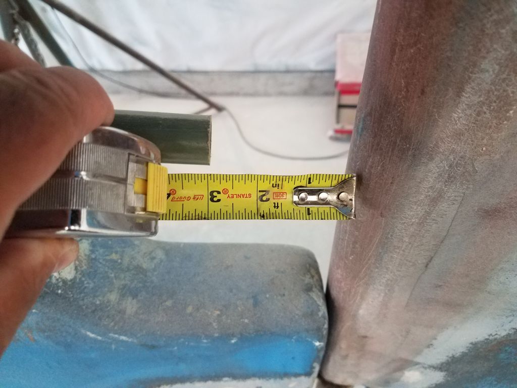
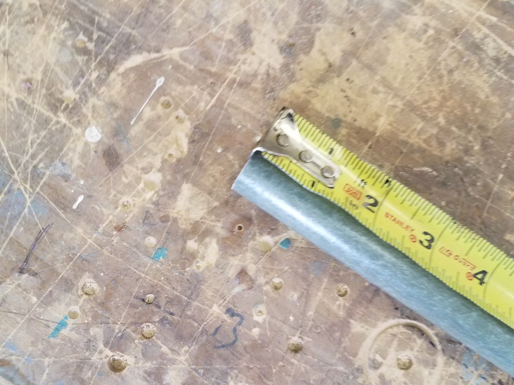
With the motor where it belonged, outside the boat I measured for the actual shaft length. The piece of fiberglass I was using ended 3″ forward of the rudder, and after reviewing photos of the original configuration and how far aft the shaft projected, I decided that the new shaft should be 2″ longer than whatever the length of my fiberglass stand-in was. This would leave 1″ clearance between the shaft and the rudder, keep the propeller well aft for maximum aperture clearance, and still allow room on the shaft for a zinc forward of the propeller.
Now I could remove the electric motor once more and, after removing the adjustable mounting feet, I located them according to the marks I’d made, and bolted them to the engine foundation. The way these sat beneath the angle brackets, and given the confines and contours of the engine room, meant that it was much easier or even required to pre-install them like this. I would make maneuvering the manageable-yet-still-heavy electric motor into place a little more awkward (needing to be careful of marring the threads on the studs), but it would be do-able.
I’d leave things here till I could get the new propeller shaft made.

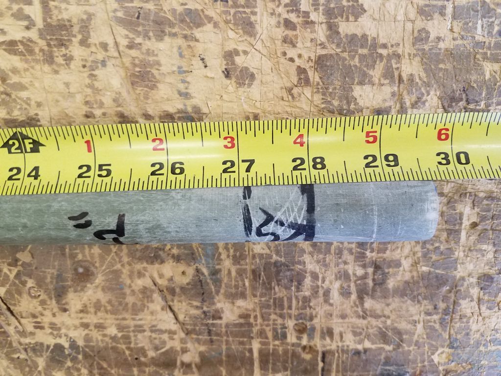
With my temporary shaft out of the boat and the coupling removed, I measured the full length (29-3/4: on the generous side), and added 2″ to obtain the final shaft length of 31-3/4″.
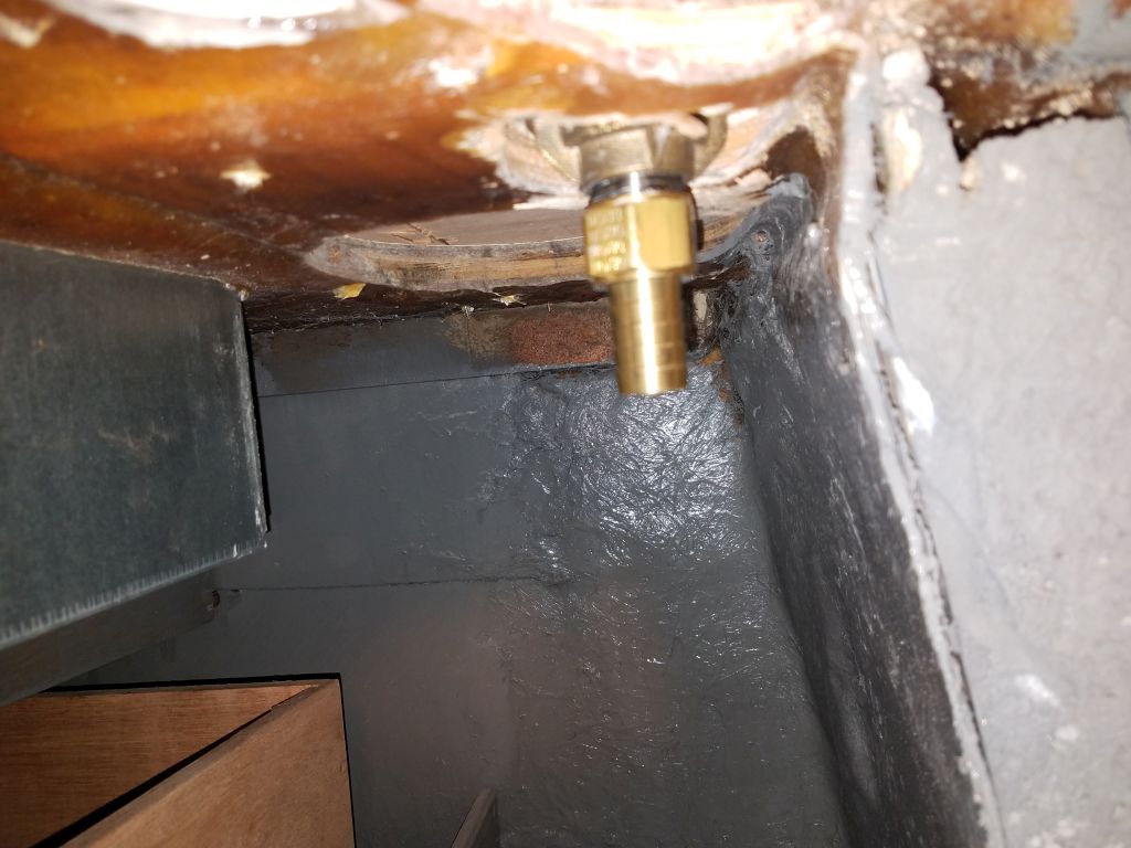
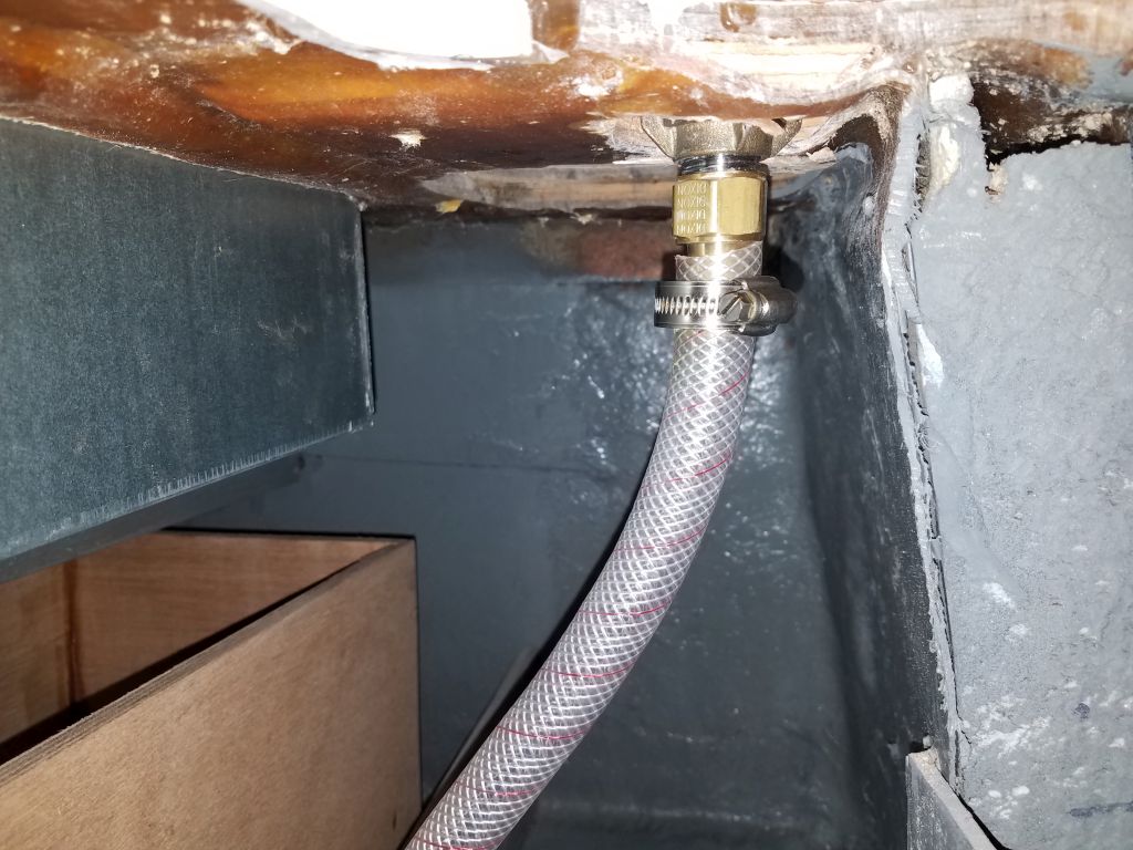
Later in the day, after my delivery of the fitting required to finish off the faucet installation, I did indeed finish the installation, threading on the female pipe-hose fitting with pipe dope, and securing a length of hose now to make it easier later on.
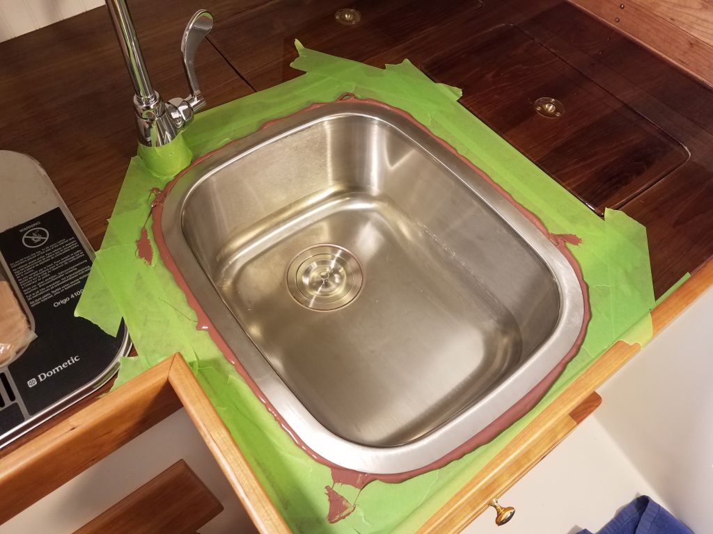
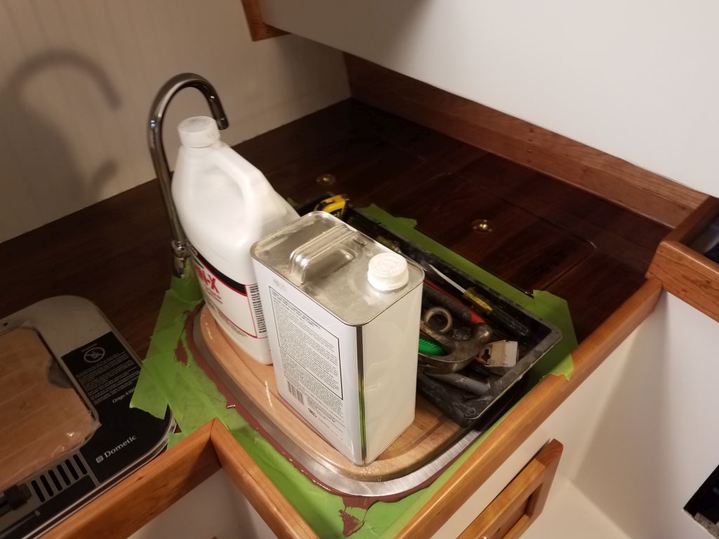
With that complete, I installed the sink permanently in a bed of adhesive sealant, weighting it down till the adhesive cured by filling the sink bowl full of tools, with additional weight on top of the sink board.

Total time billed on this job today: 4.5 hours
0600 Weather Observation: 58°, fog, clouds, showers. Forecast for the day: Showers and rain, 69°