

January 24, 2020
Scupper 227
Friday
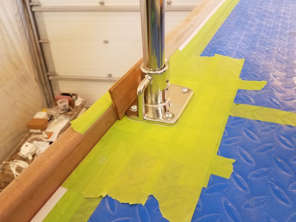
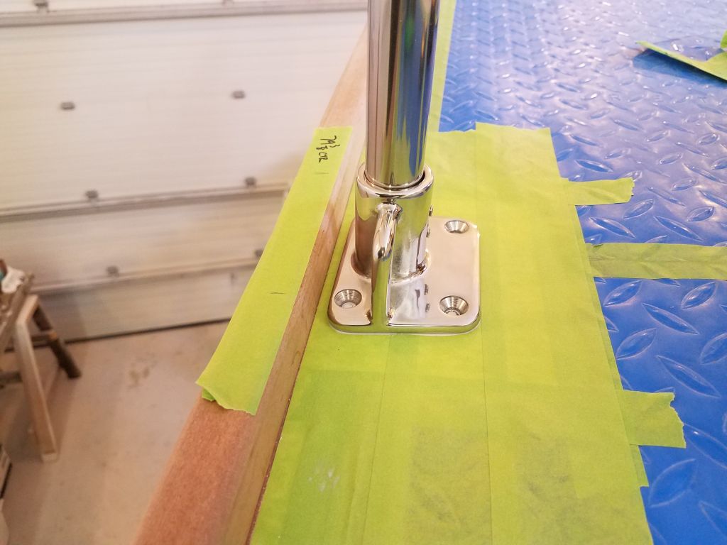
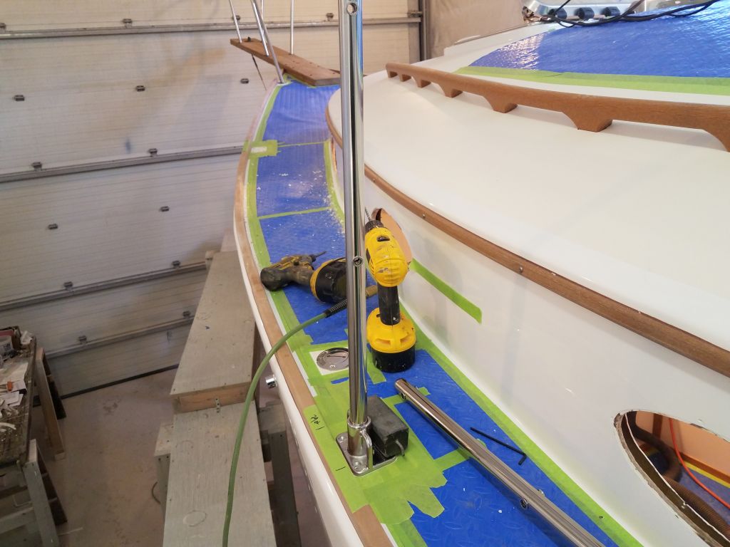
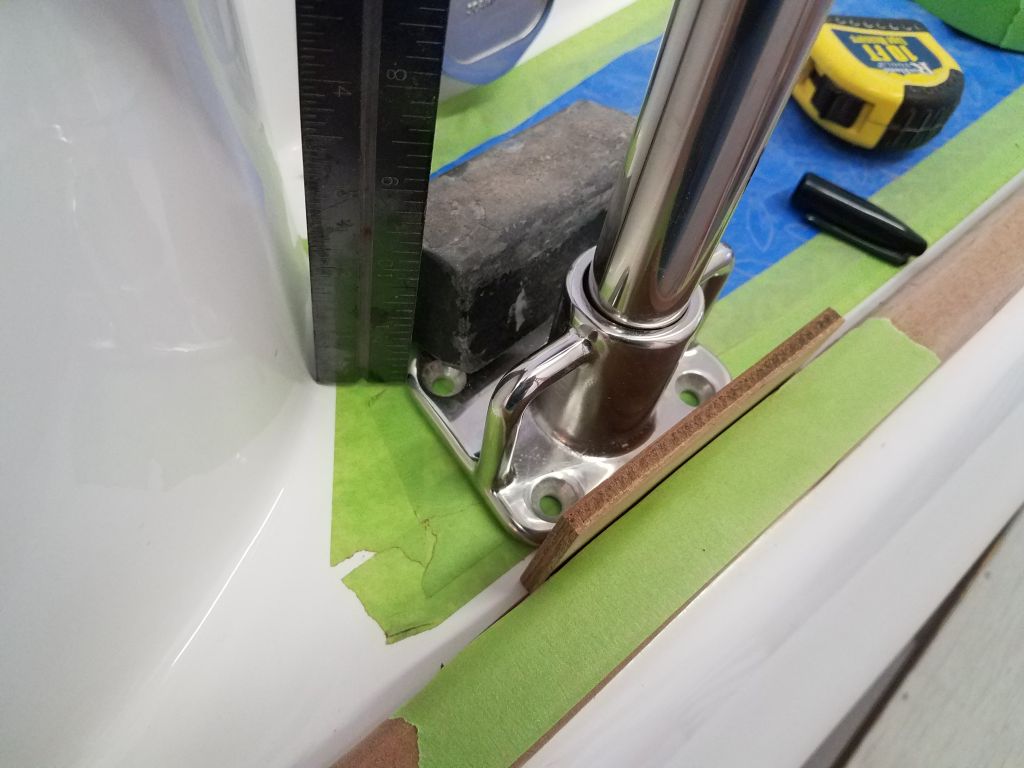
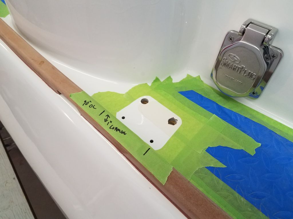
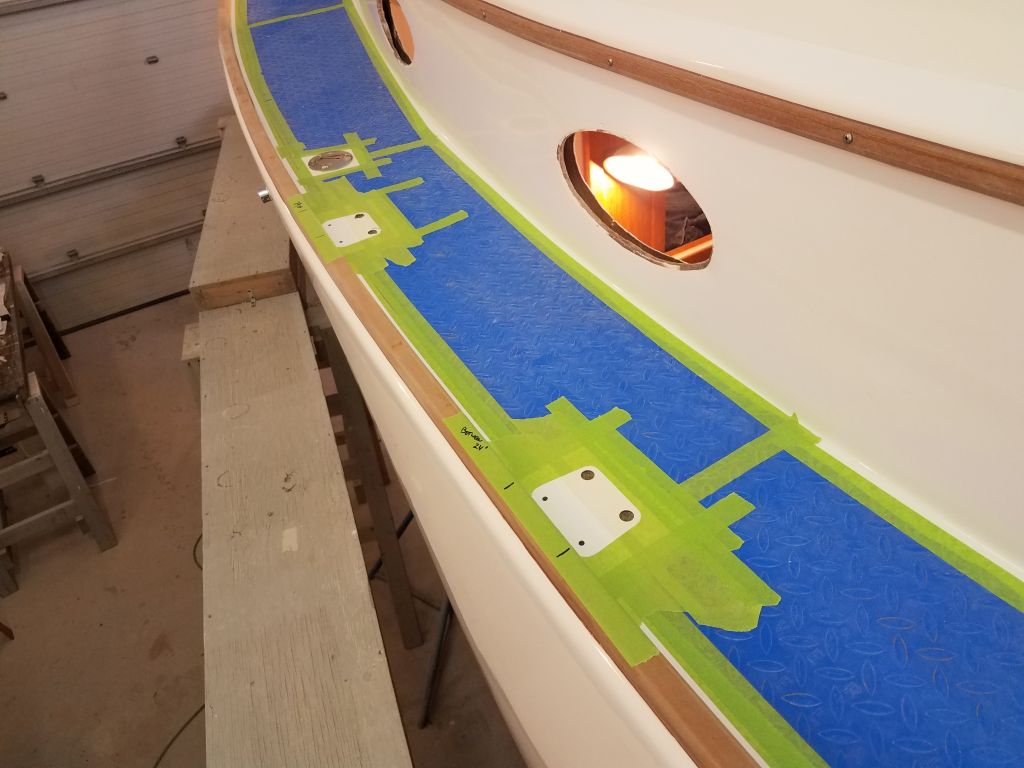
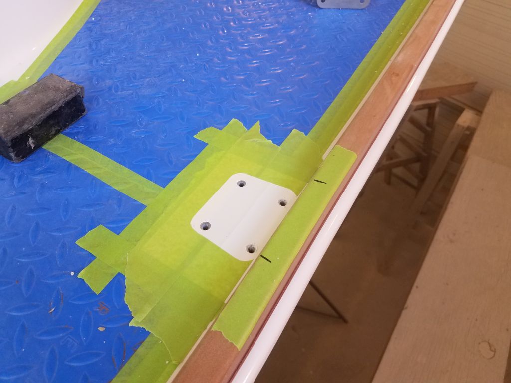
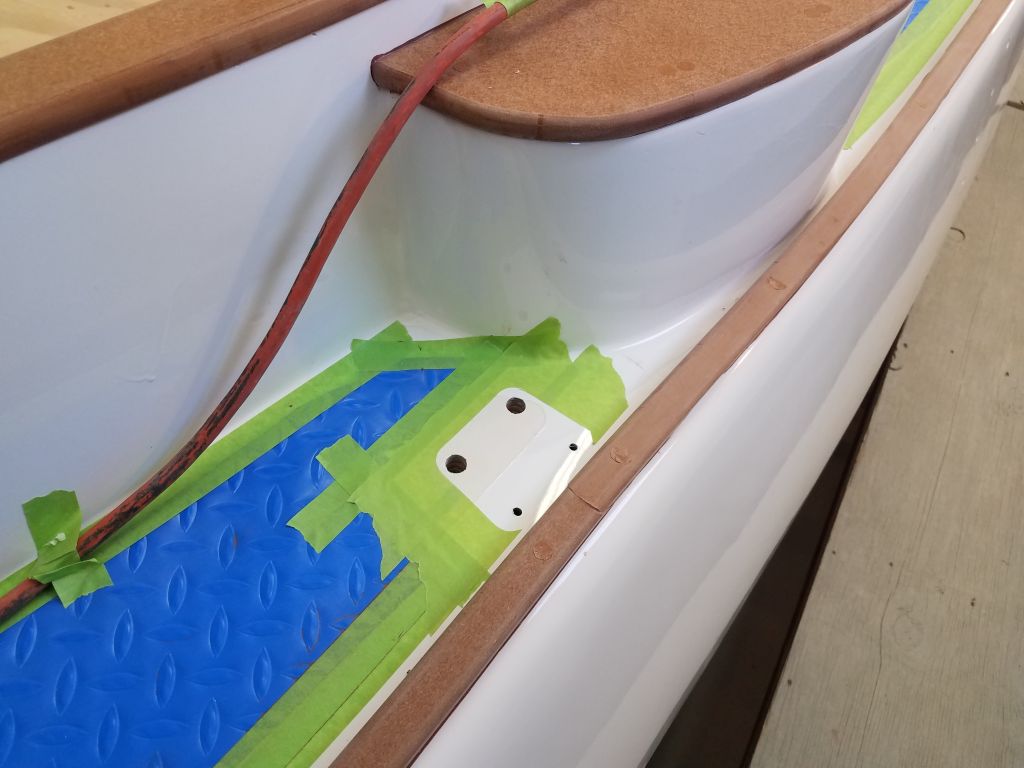
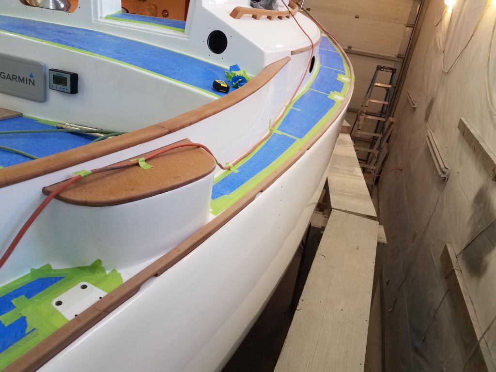
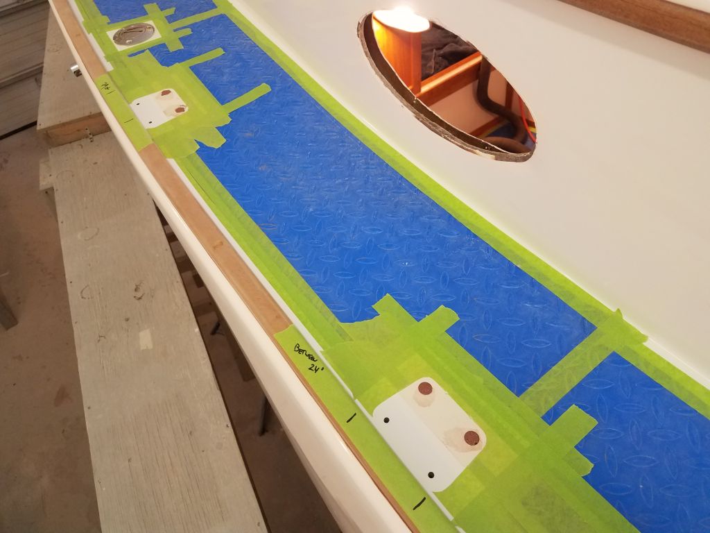
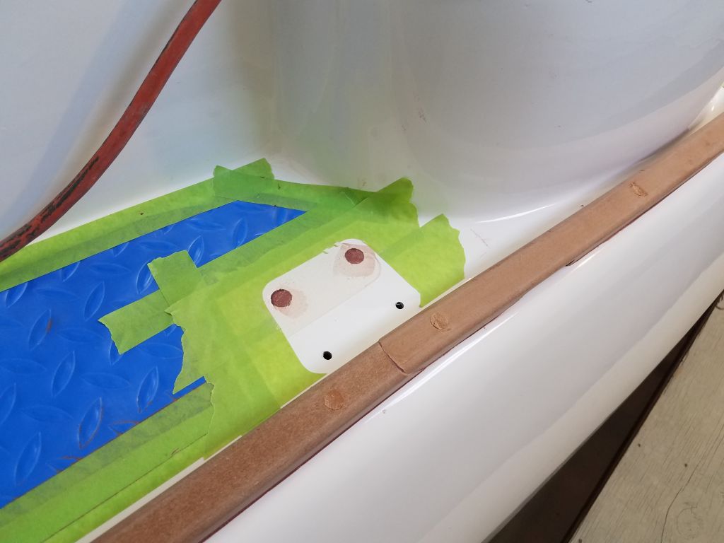
On hand I had two of the eight new stanchions and bases required, but this was enough for me to start the final layout and deck preparations. Starting on the port side, where I’d done the initial new layout, I prepared the deck in way of each new stanchion base by cutting away the plastic deck cover and installing masking tape, before placing the stanchion base 1/4″ inboard of the toerails (using a wooden spacer) and, after confirming the stanchion placement and measurements, marked and drilled fastener holes, and removed masking tape beneath each footprint. I made notations as to the stanchion’s measurements that I could refer to later when replicating the layout to starboard.
On the port side, the forward stanchion holes penetrated solid deck, with no core, so I could complete the hole preparation by tapping for machine screw threads and milling a countersink at deck level, but the inner sets of holes at the after three base locations on this side went into cored sections of the deck, so for those holes I drilled 1/2″ holes through the top skin and core to remove the core around the eventual fastener locations.
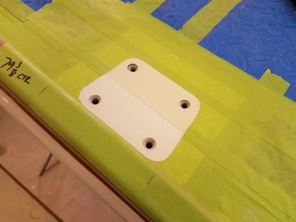

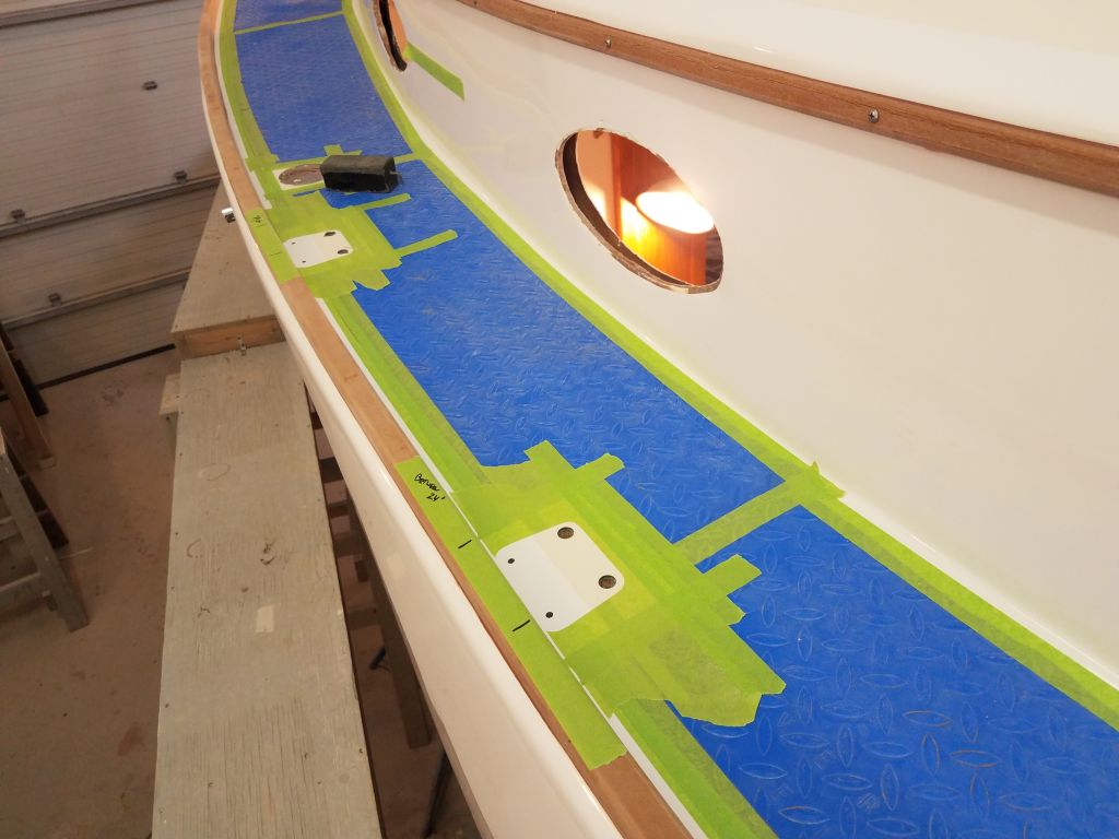
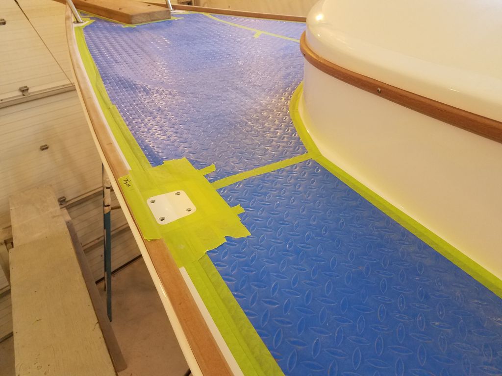
Next, I repeated the layout and prep process on the starboard side, using the measurements from the port side as a guide. Here, with the original deck construction still in place, all three forward stanchion locations featured solid fiberglass at all four hole locations, and only the aftermost base (aft of the winch island) required overboring for the inner set of holes.

Finally, I filled all the overbored holes I’d prepared with a thickened epoxy mixture. Now everything would be ready for final installation as soon as I received the additional new stanchions and bases.

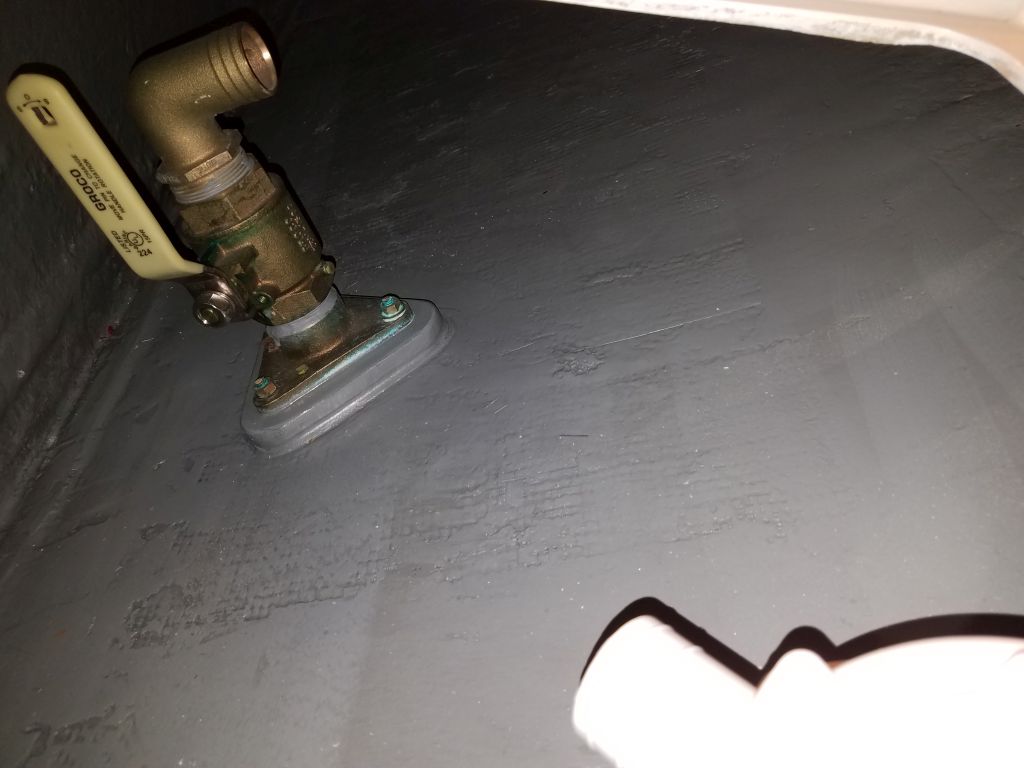
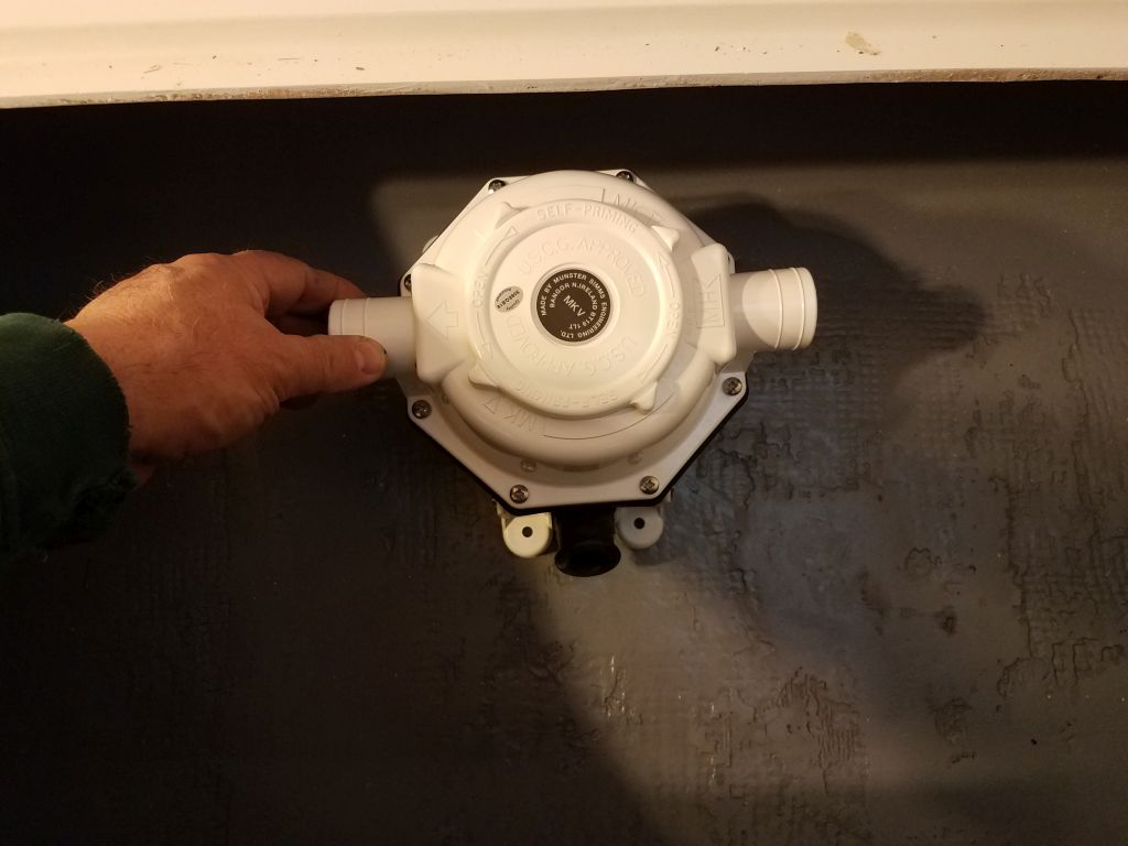
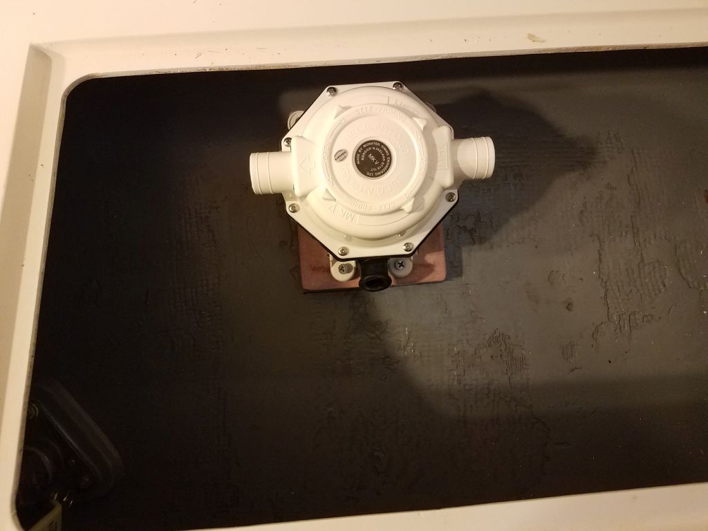
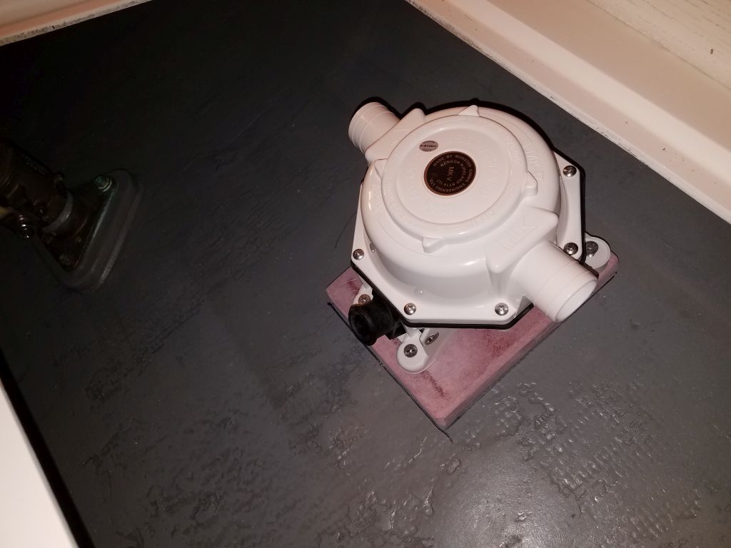
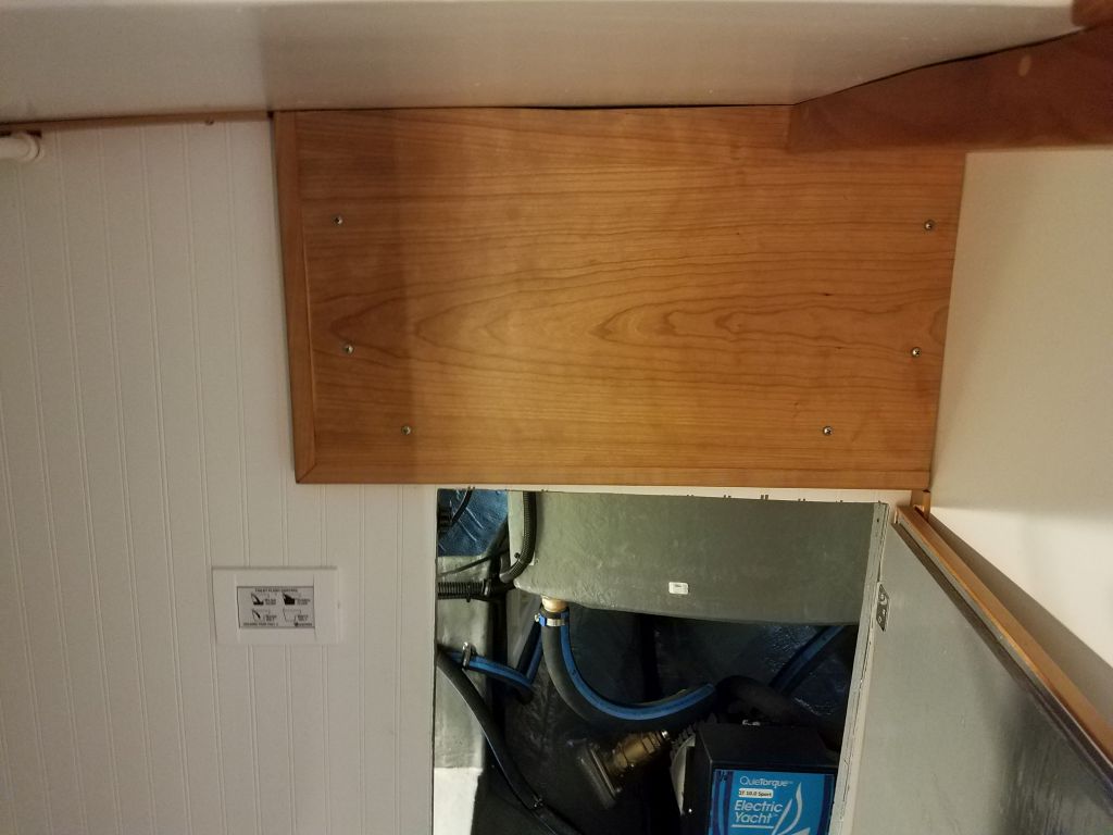
The head setup included the ability to pump the holding tank overboard in areas where it might be legal, and to this end I’d ordered a manual sanitation pump for the purpose. This would have to be mounted to the hull inside the starboard settee lockers, nearby the through hull designated for this purpose, so I began with a quick dry fit to see where the pump should go. As arrived from the factory, the intake and discharge ports were cocked at an angle to the axis of the pump, which wouldn’t work effectively in this situation, so to begin I repositioned the top of the pump–which included the ports–to a different alignment that would work better, a simple matter of removing the fixing screws, rotating the housing, and reattaching. This new alignment would better allow the hoses to run freely between the holding tank locker, pump, and through hull.
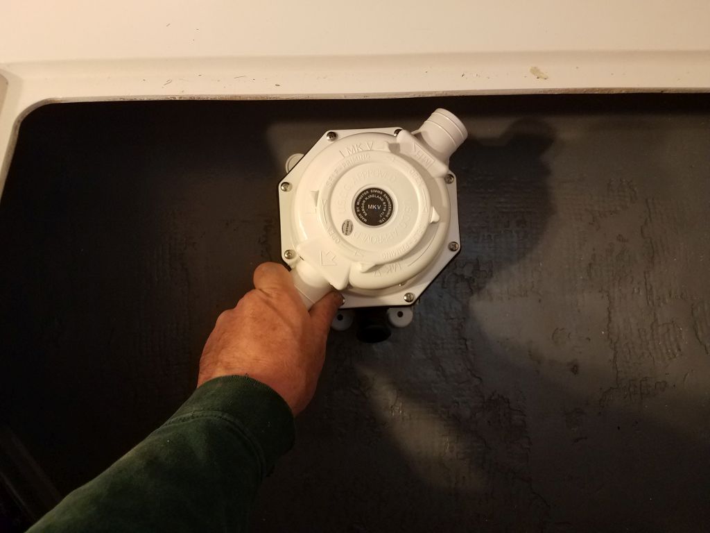
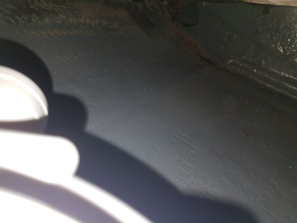
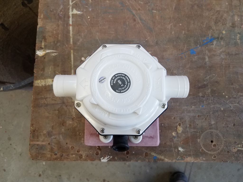
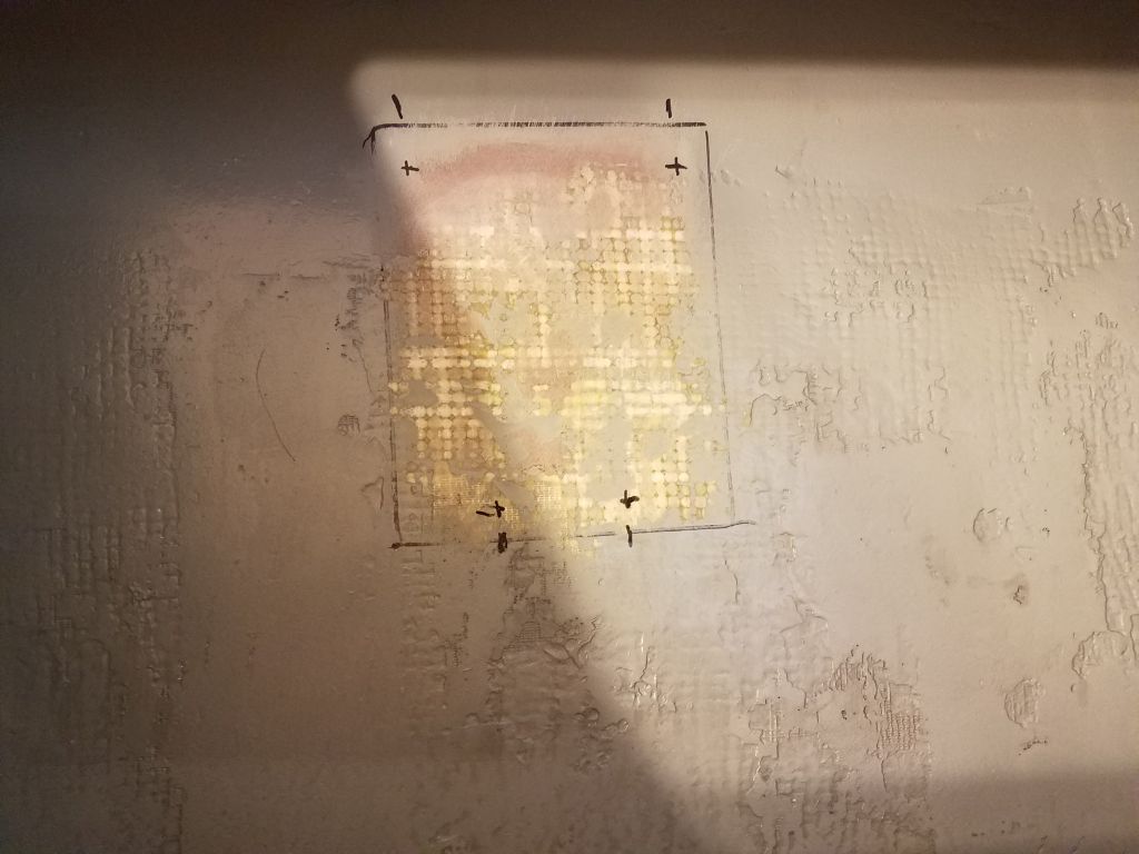
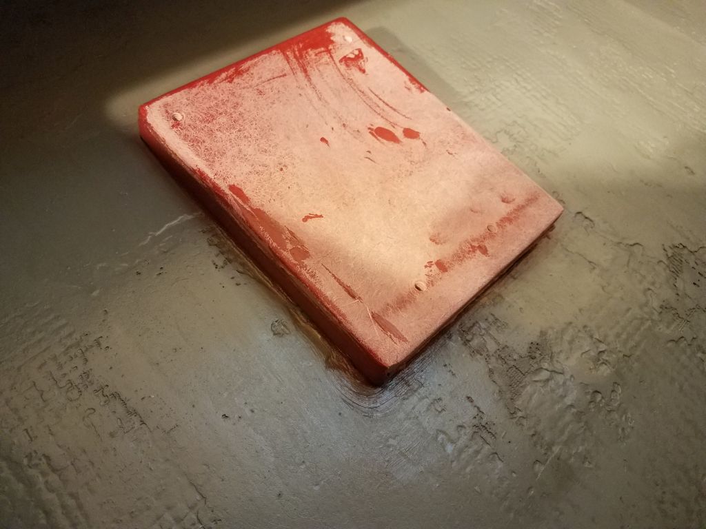
To mount the pump, I needed a base on the hull, so from some leftover 3/4″ prefab fiberglass I cut a base to fit the pump, and after smoothing the edges and predrilling/tapping for 1/4″ machine screw fasteners, and sanding away the paint in the locker, I epoxied the base in place on the hull. Once the epoxy cured and I could paint the base, I’d install the pump with the fixing screws for which I’d prepared it, and run the hoses.


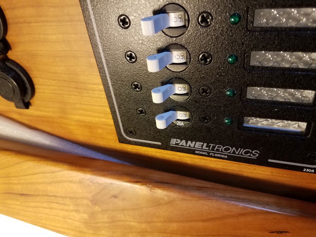
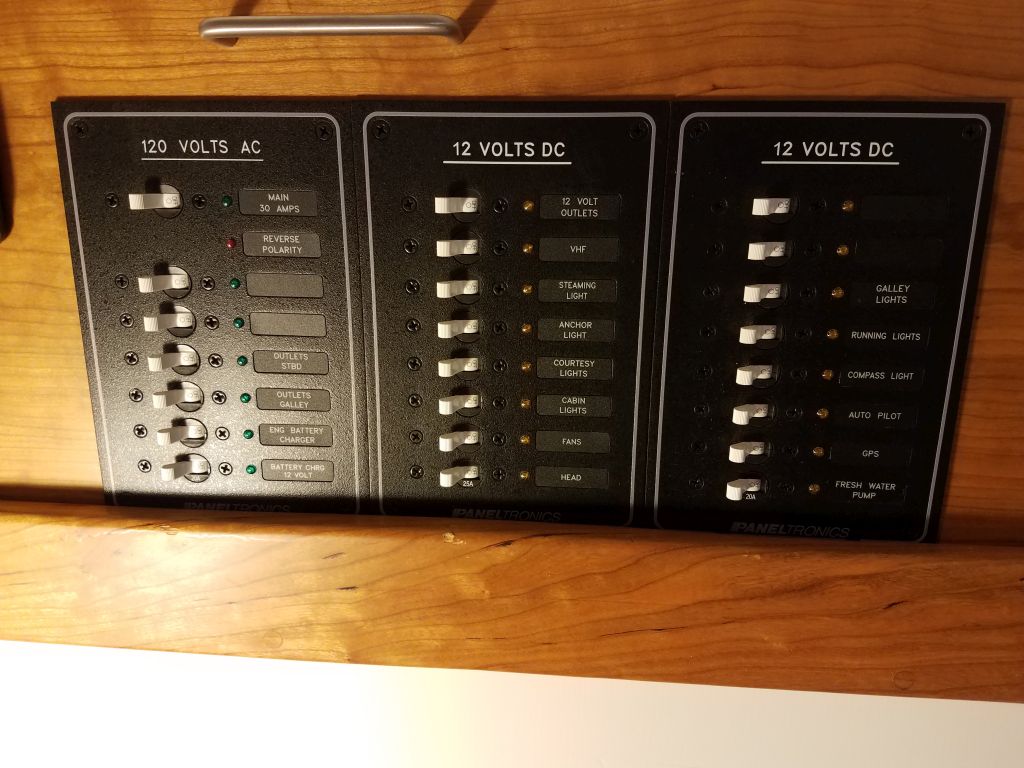
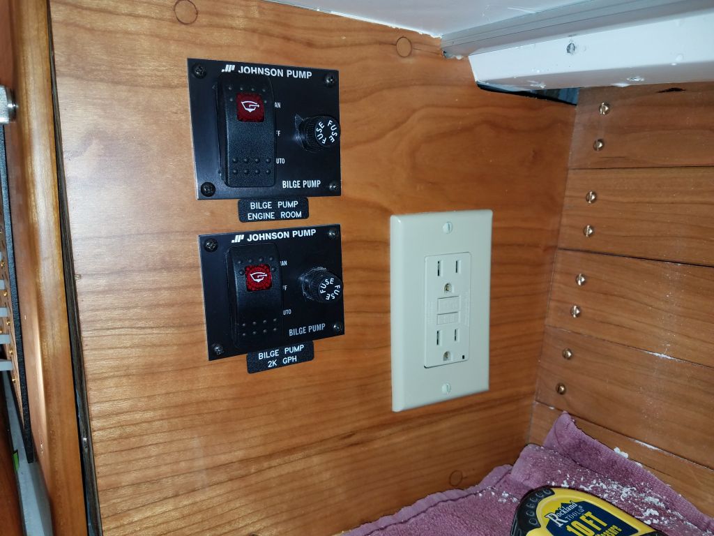
During the electrical work, one of the AC circuit breaker handles had broken off, so now I replaced the damaged breaker with a new one. Afterwards, I installed the labels I’d ordered for the panel circuits and bilge pump switches.

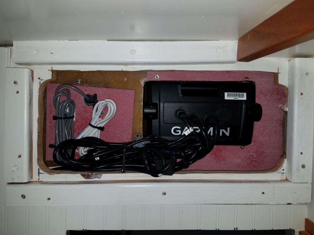
The day’s courier delivery brought me the Garmin transducer cable adapter I needed, so with that I completed the GPS and associated wiring, secured the excess cabling, and reinstalled the cosmetic cover panel in the head.

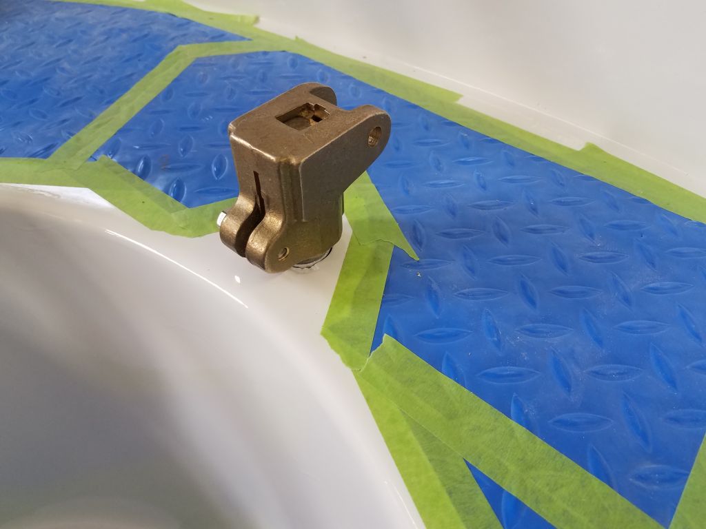
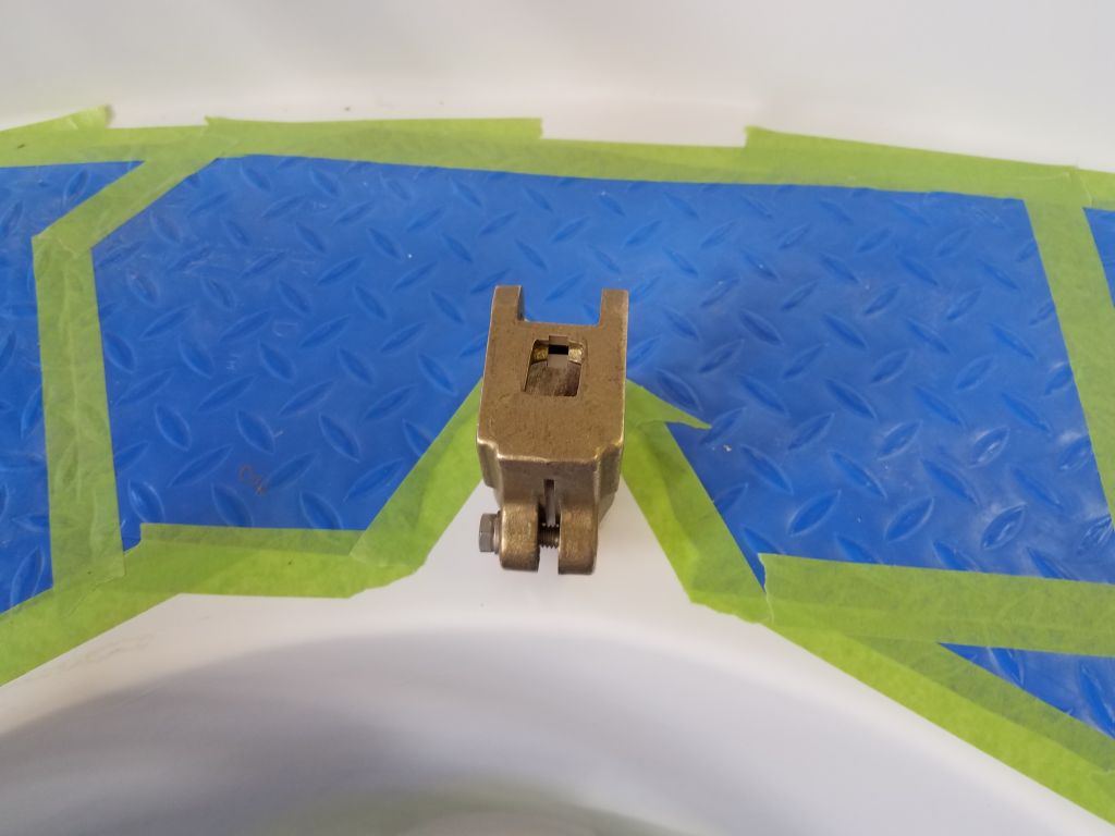
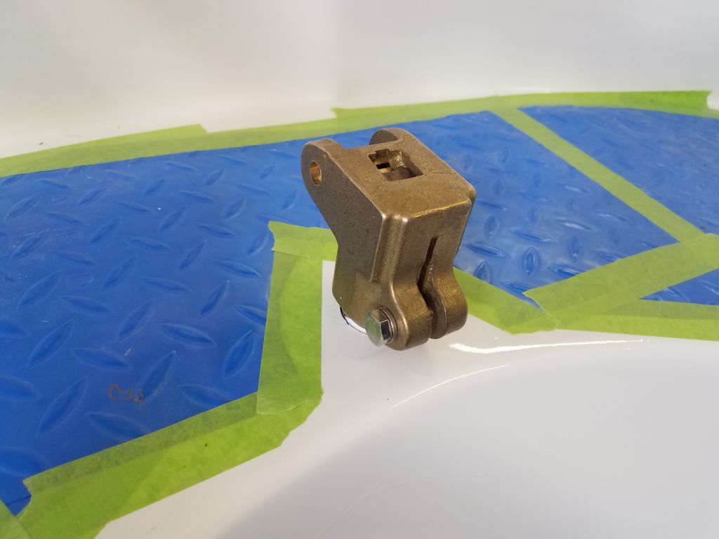
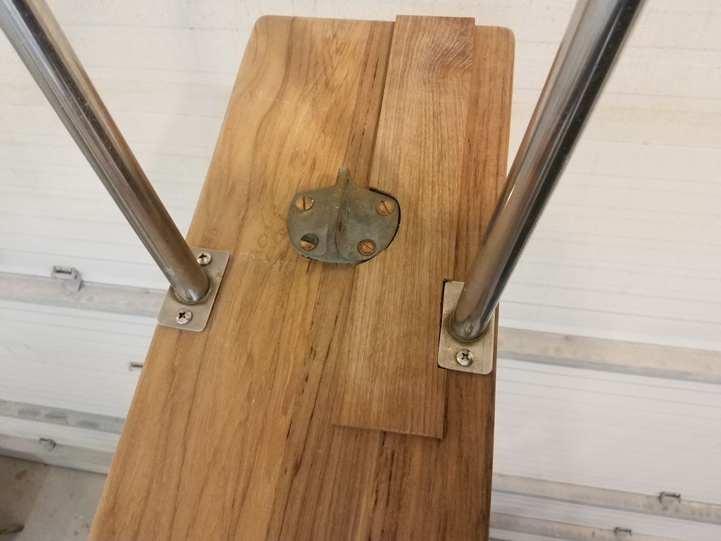
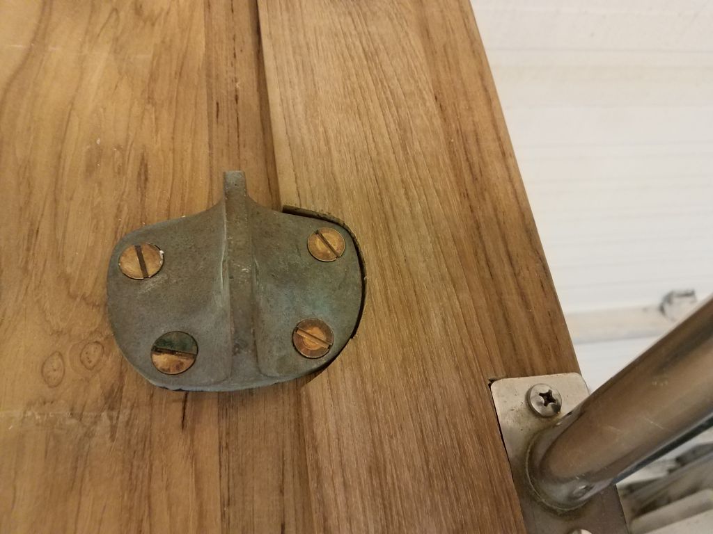
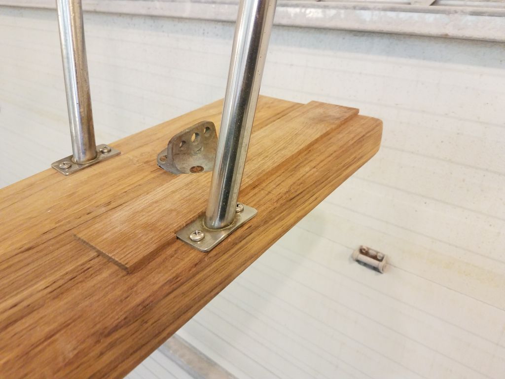
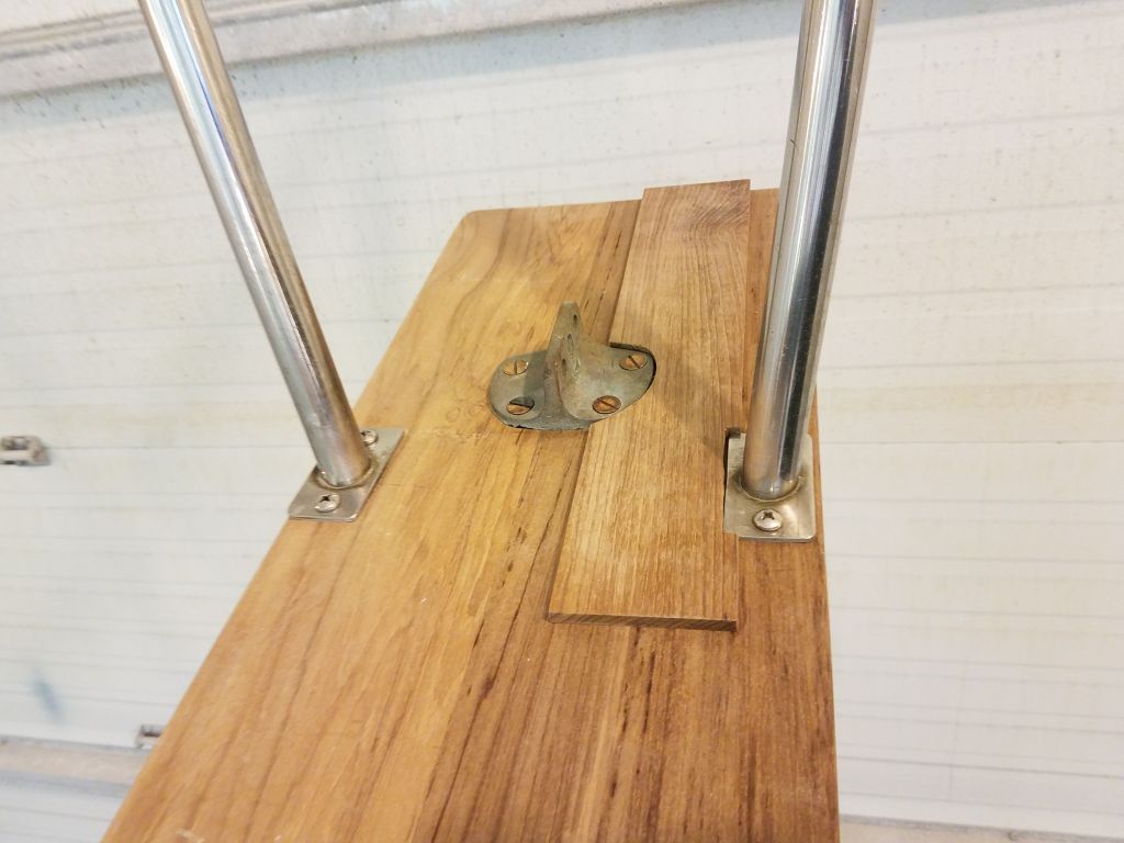
I’d had it lying around for some time, but now I finally got around to installing the new bronze tiller head on the rudder post. I’d removed the tiller strap for the purpose, and kept it in the shop for the moment till I could start designing and building the new tiller sometime later in the project.
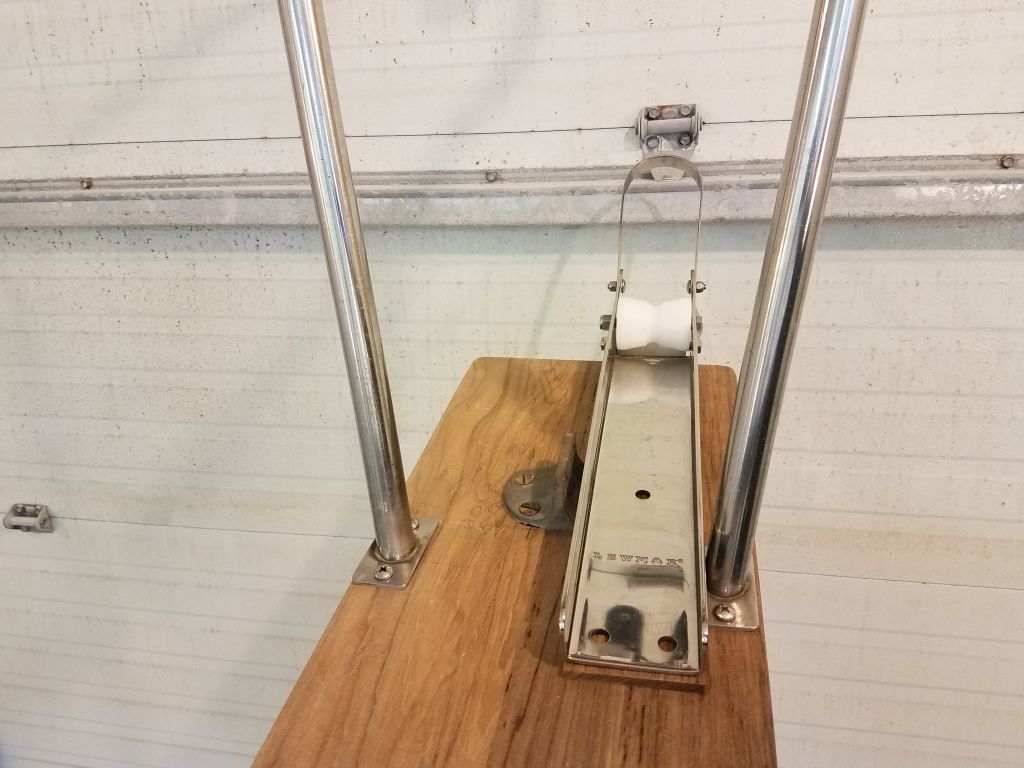
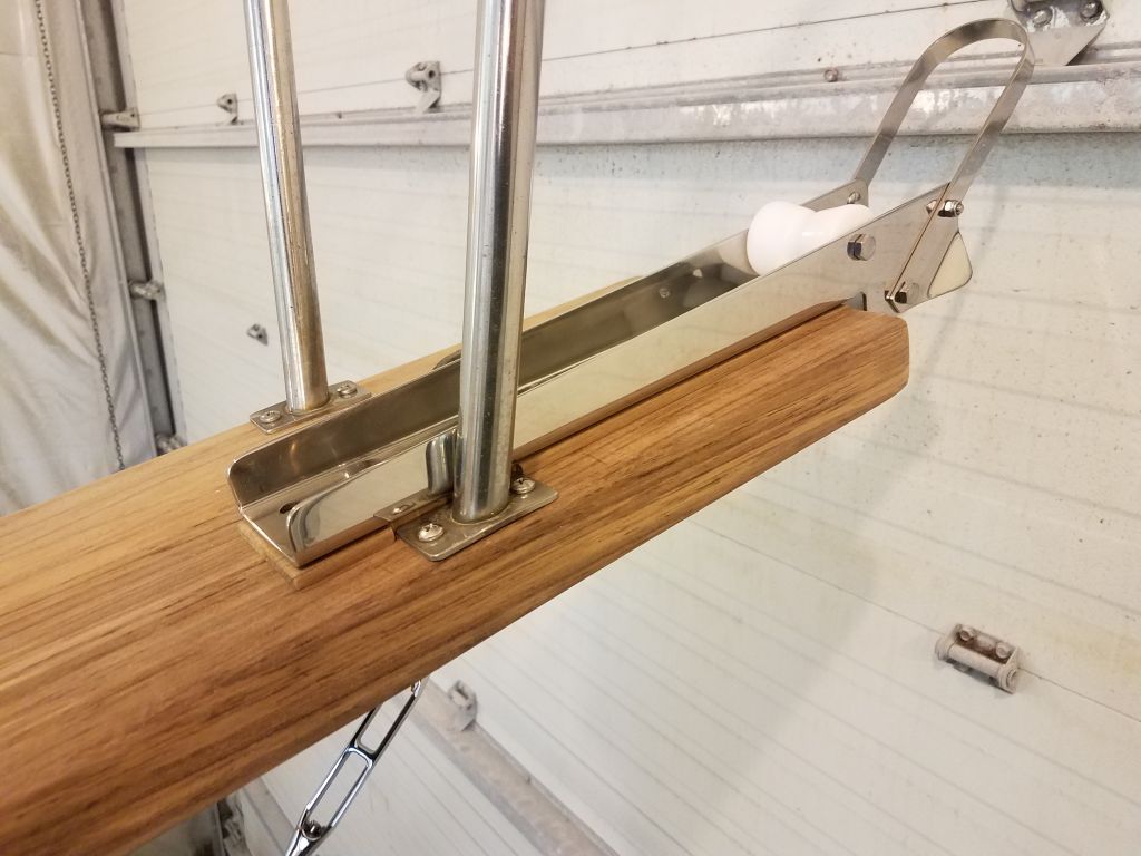
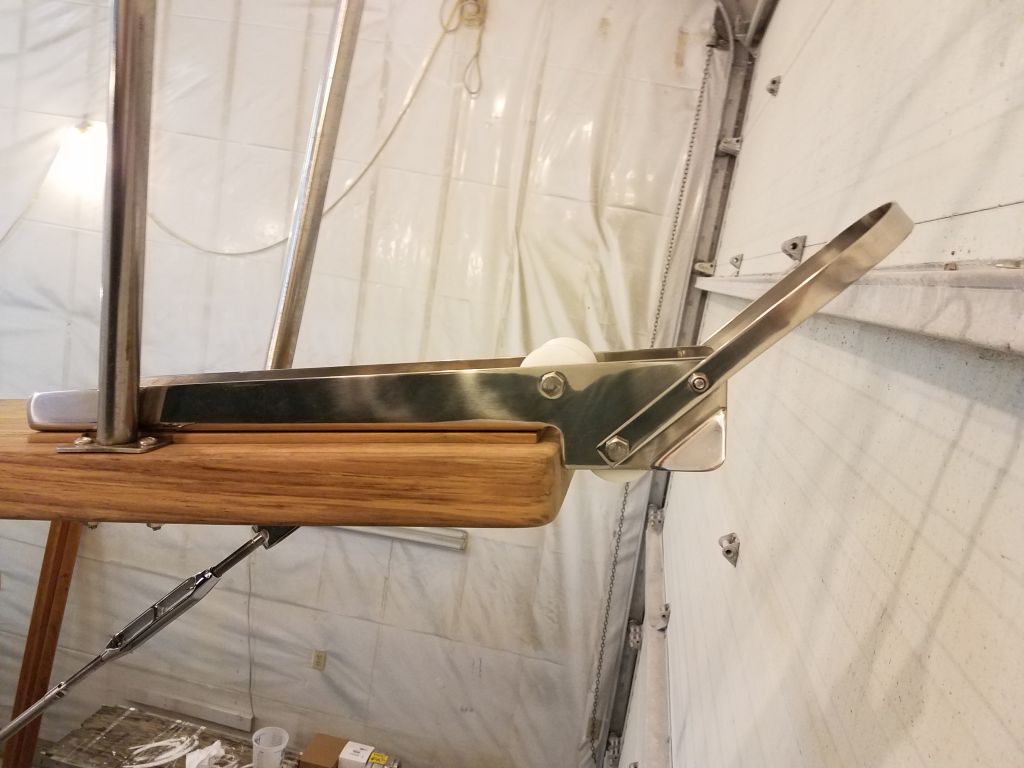
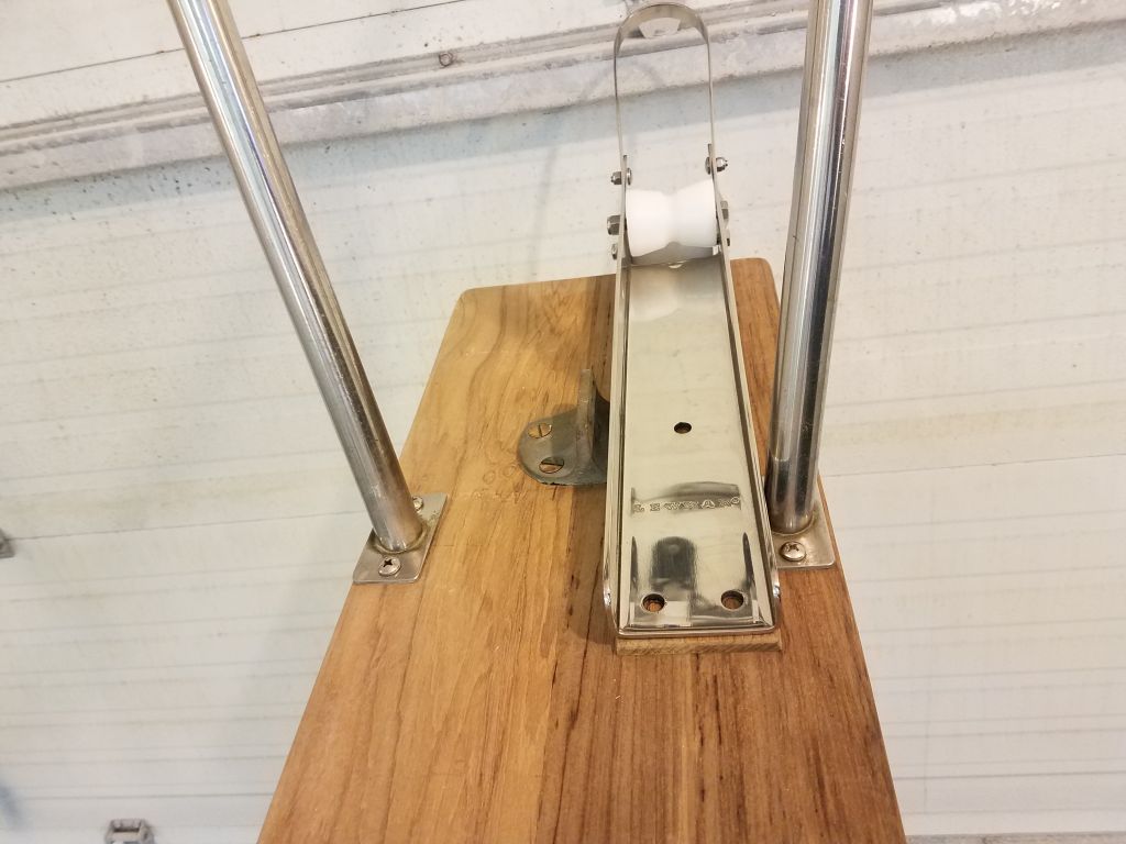
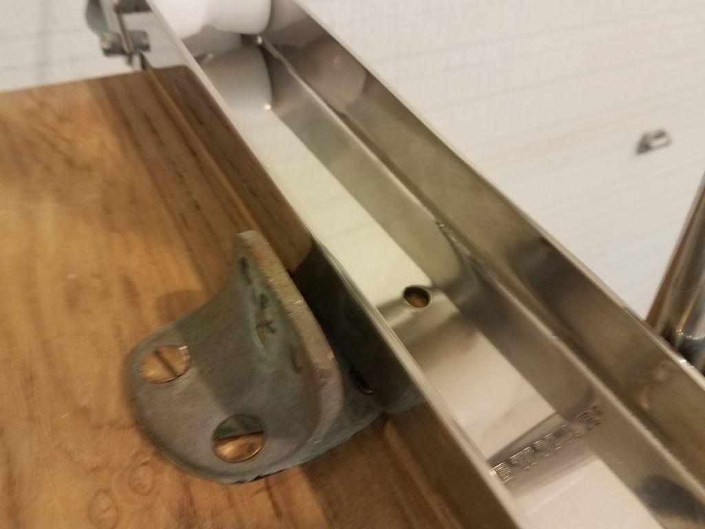
Earlier in the week, I’d ordered the anchor roller designed to fit the owner’s choice of Delta anchor, but I worried that the space on the bow platform was more limited than I’d originally anticipated, thanks to the pulpit bases intruding. Because of this, I’d ordered three additional types of anchor rollers as a trial, hoping one of the smaller, narrower ones might work, but unfortunately all the smaller ones simply weren’t up to the task of the anchor at hand.
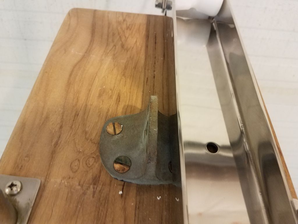

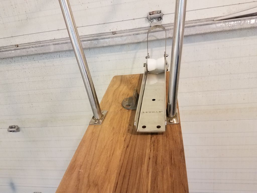
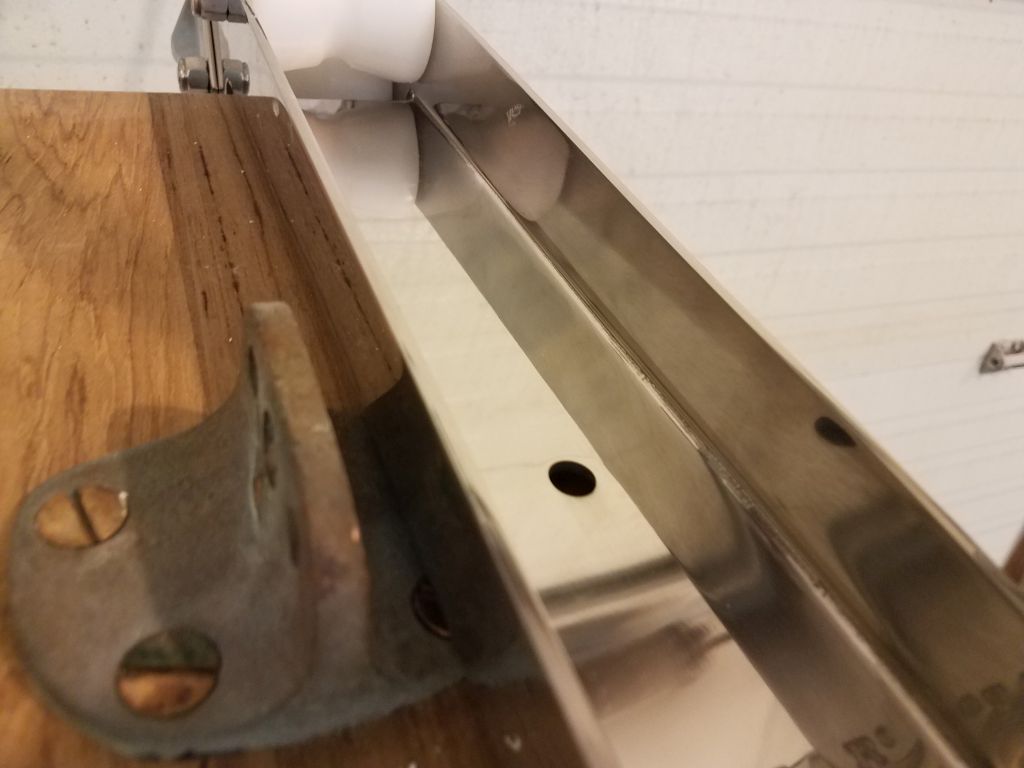
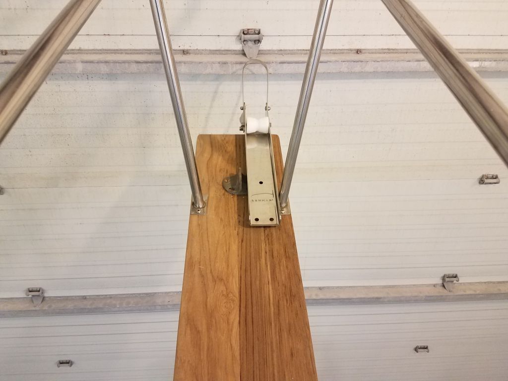
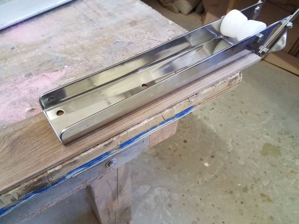
At issue with the Delta roller was the fact that the space between the headstay attachment point and the pulpit mount was narrower than the roller itself, and also there was a clearance issue (potential) between the headstay attachment and the side of the anchor roller. But now that I’d discounted any of the other rollers as a possibility, I took another hard look at the situation, and realized that with a 1/4″ spacer beneath the roller, and cut to fit around the impediments, the roller would otherwise work as intended–provided I could pre-install the lower toggle on the new roller furling headstay assembly, since access to the clevis pin and/or cotter pin would be limited or impossible with the roller in place. Otherwise, there was room for the toggle to fit, and with the 10″ raised height of the furler drum I’d requested, there would be no other access or clearance issues.
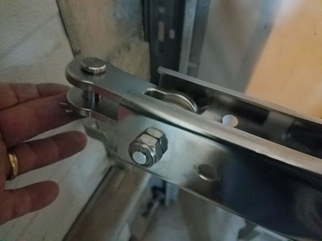
At first glance, it looked straightforward to remove the toggle from the headstay, but it turned out that the pin securing it and the headstay turnbuckle was more complicated than that, featuring a pair of nuts, spacers, and even a cotter pin inside the assembly. What I thought would be a simple bolt removal turned out to be more than that, and after a quick failed attempt I regrouped and thought I would ask the riggers about it before I went ahead with the removal, as it seemed there might be a trick or two needed.

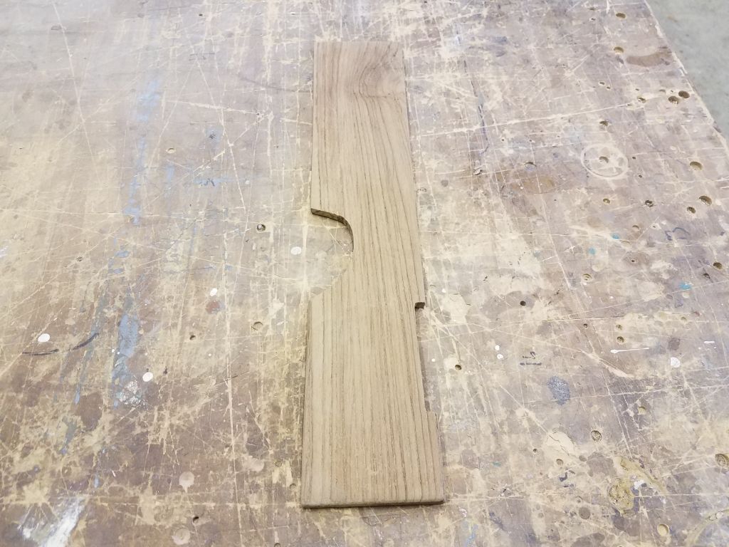
Still, one way or another I planned for this to be the way forward, so from some scrap teak I made a spacer to fit beneath the roller, with cutouts as needed to clear the two impediments, and with a dry fit I was pleased with the prospects, and the roller was right where I’d always figured it would be when imagining the windless installation. I’d await final installation till I cleared up the toggle issue, but was glad I’d found a workable and practical solution to the tight quarters at the end of the bowsprit.


Total time billed on this job today: 7.5 hours
0600 Weather Observation: 20°, partly clear. Forecast for the day: Partly sunny, 37°