

January 30, 2020
Scupper 231
Thursday
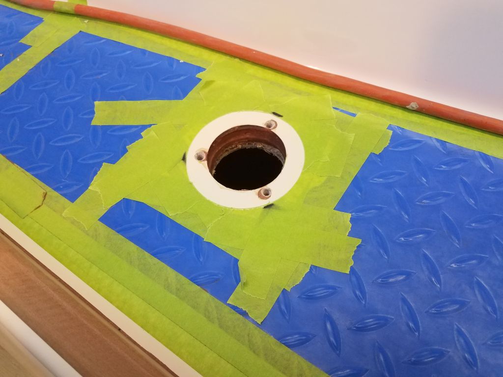
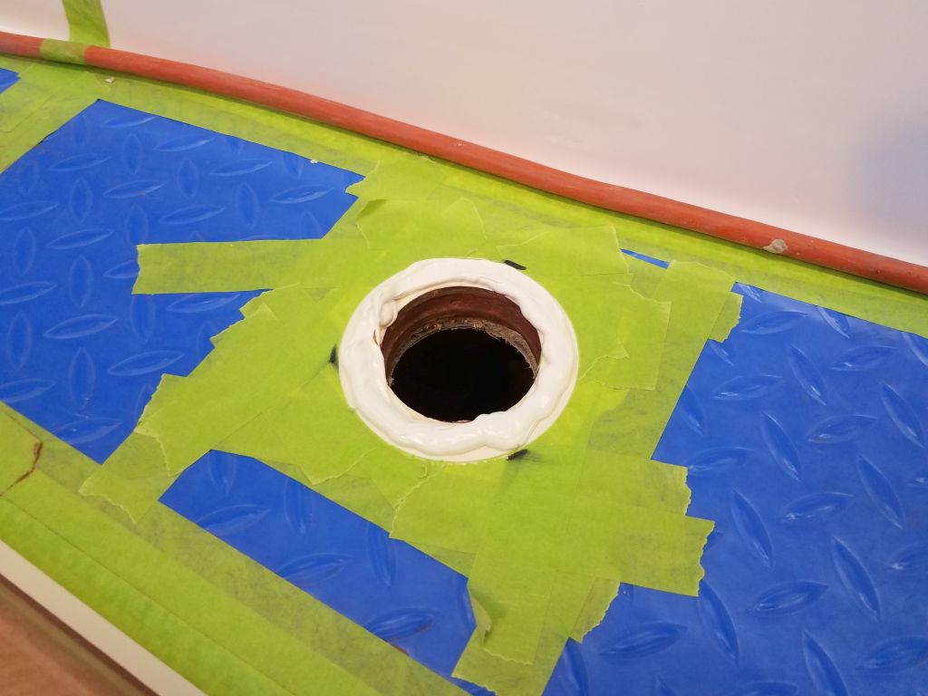
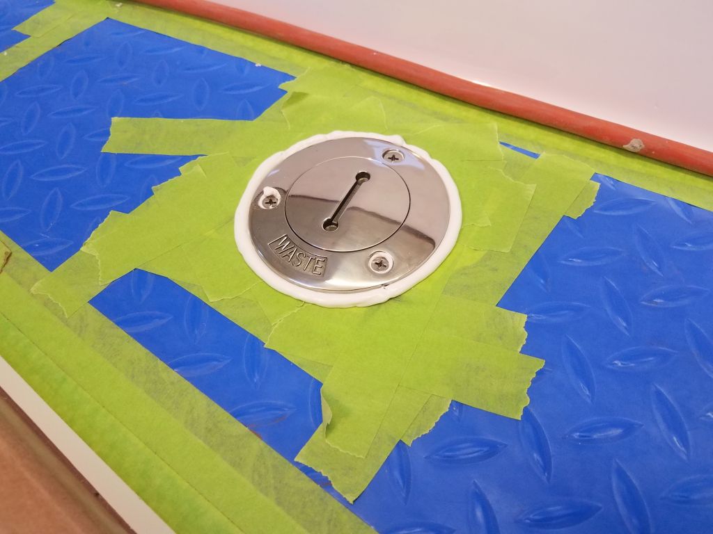
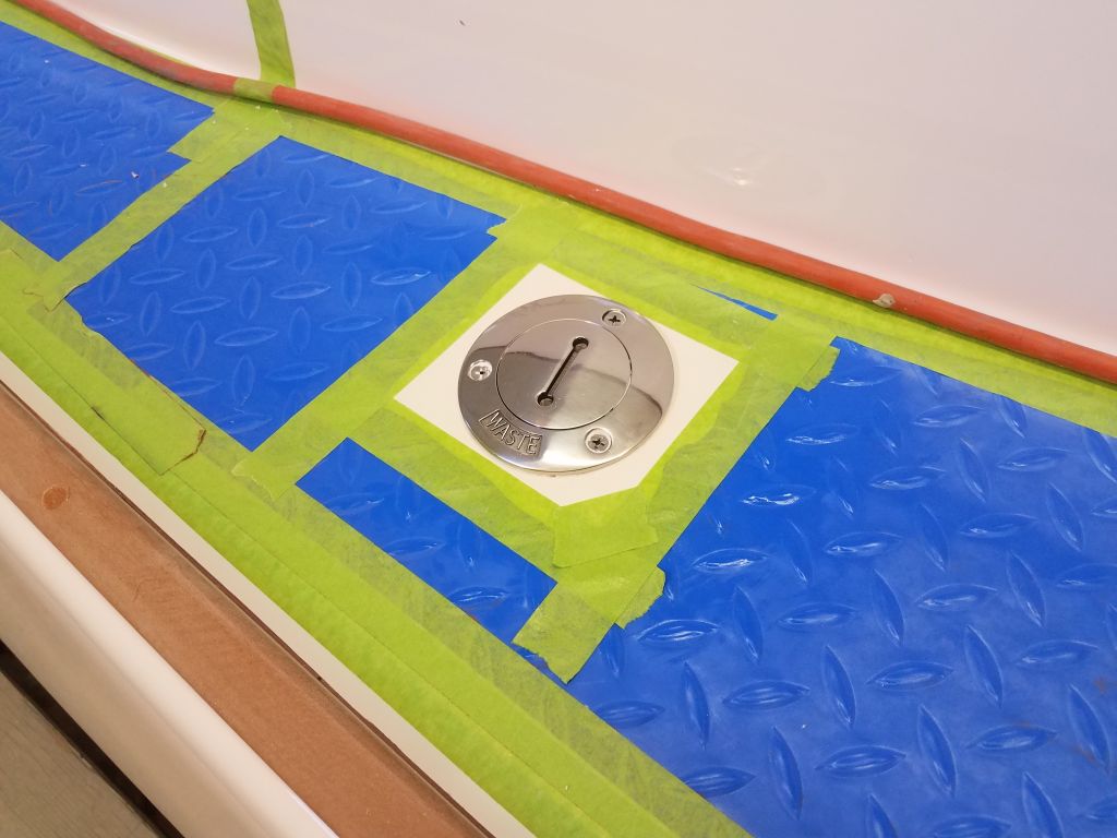
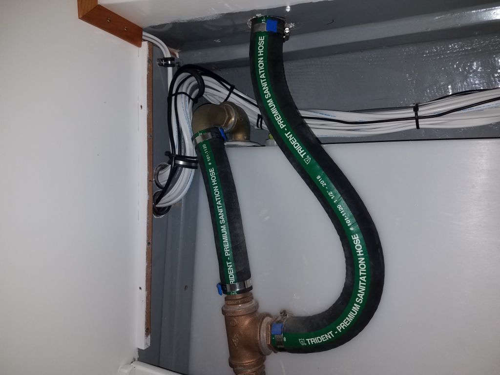
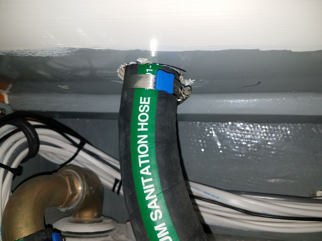
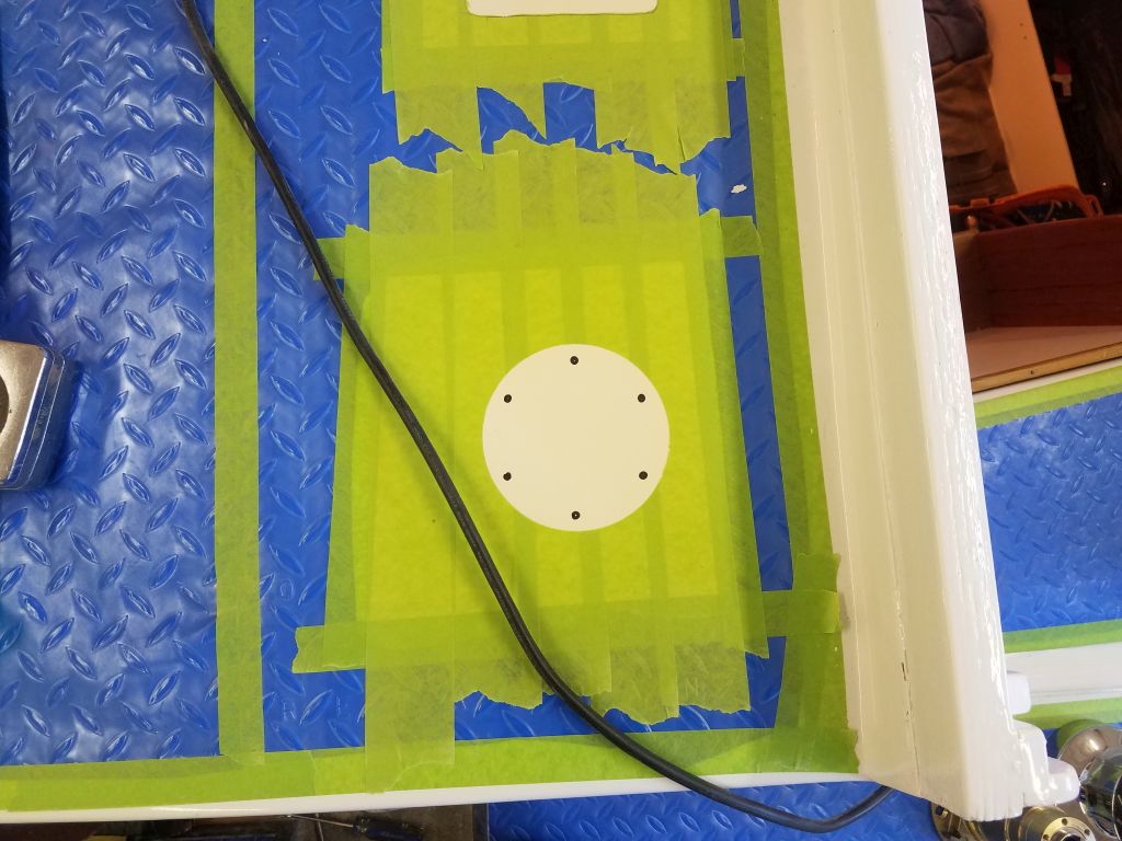
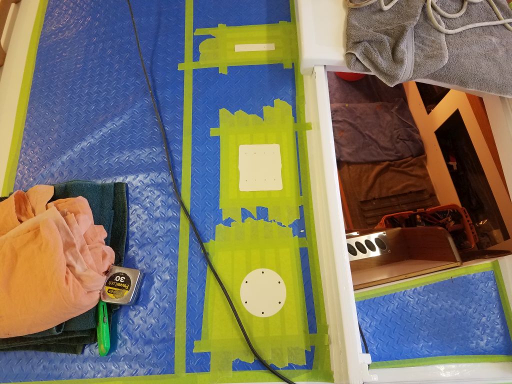
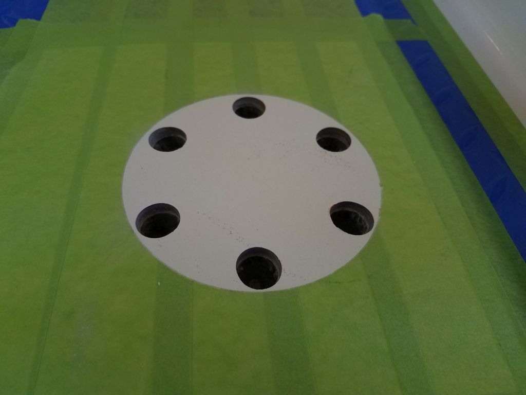
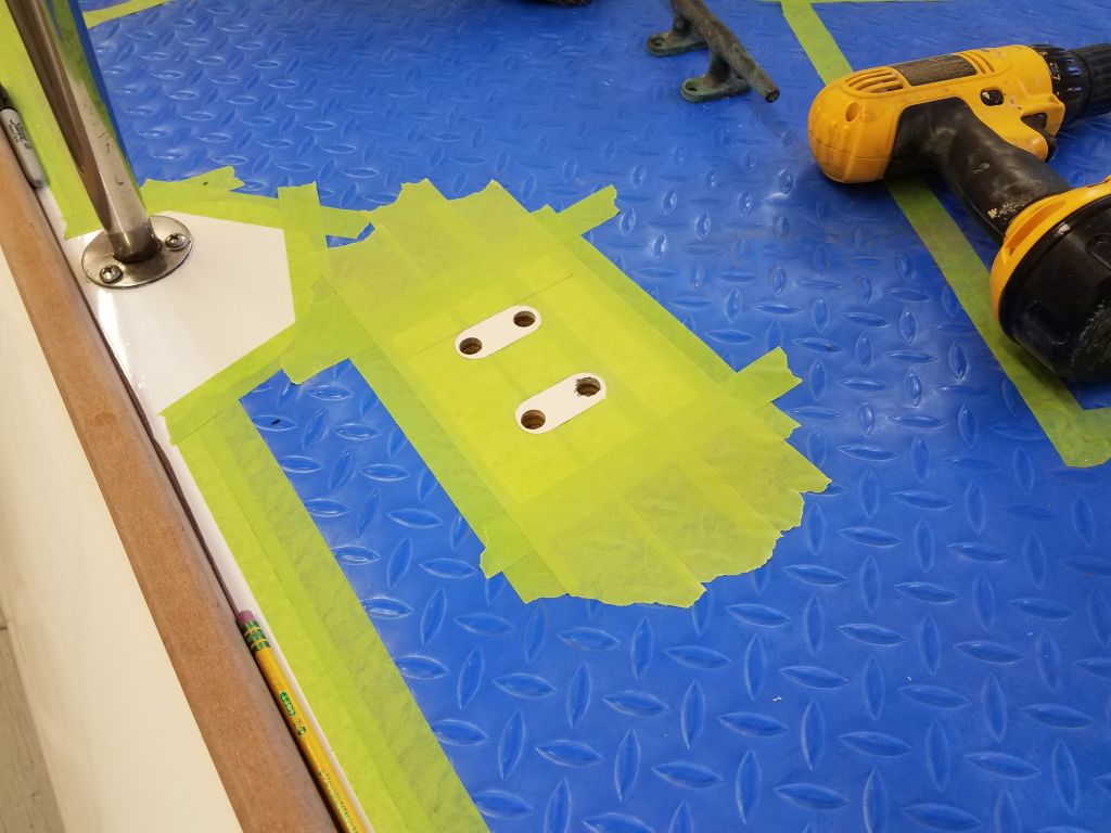
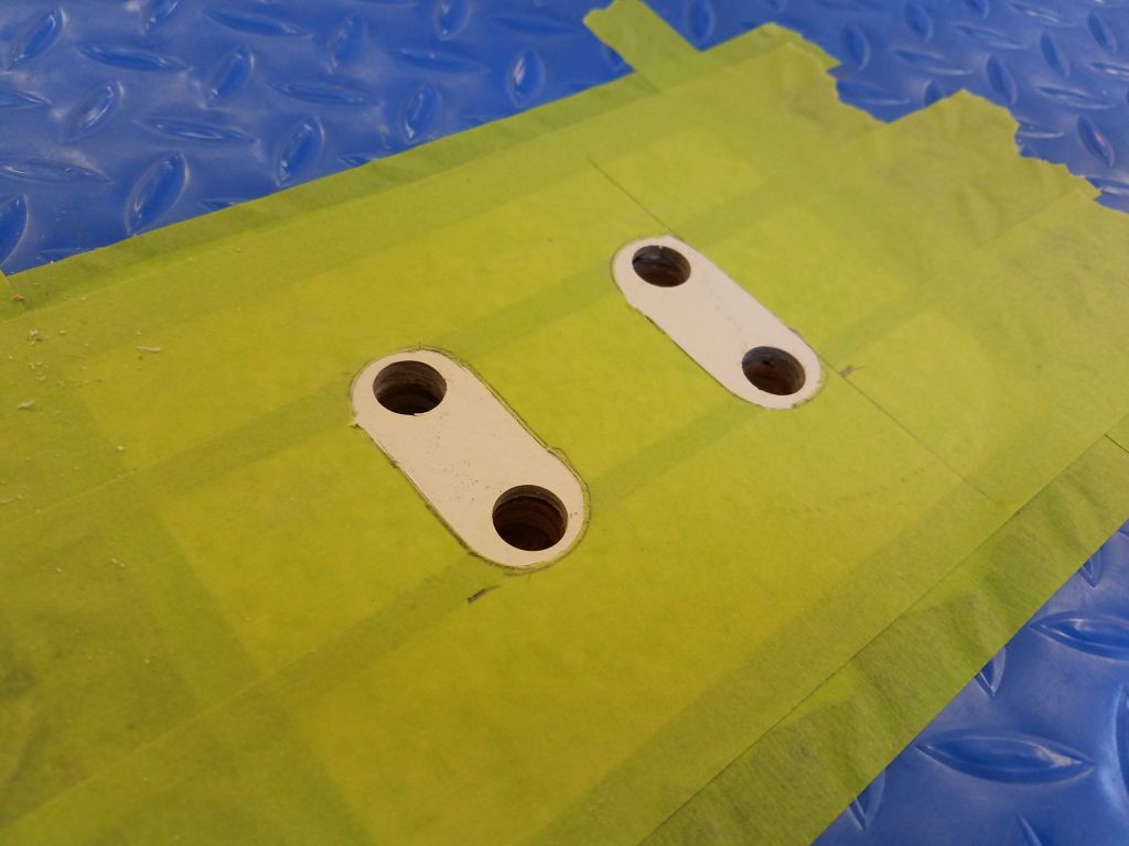
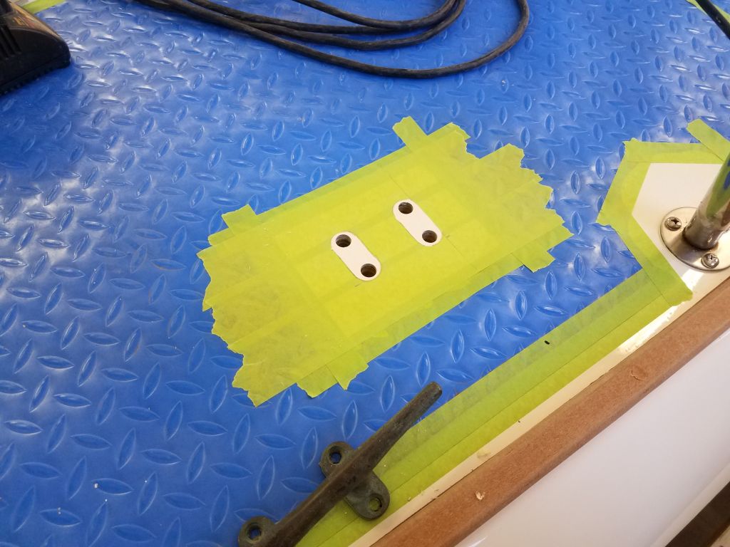
To begin the day, I finished up the new waste deck plate installation, a straightforward matter of the usual drill/tap/countersink/sealant process. Afterwards, I secured the hose belowdecks. All that remained to complete the waste system was the head installation, but I was in no rush to install that till I knew I was finished moving about in the tight space.
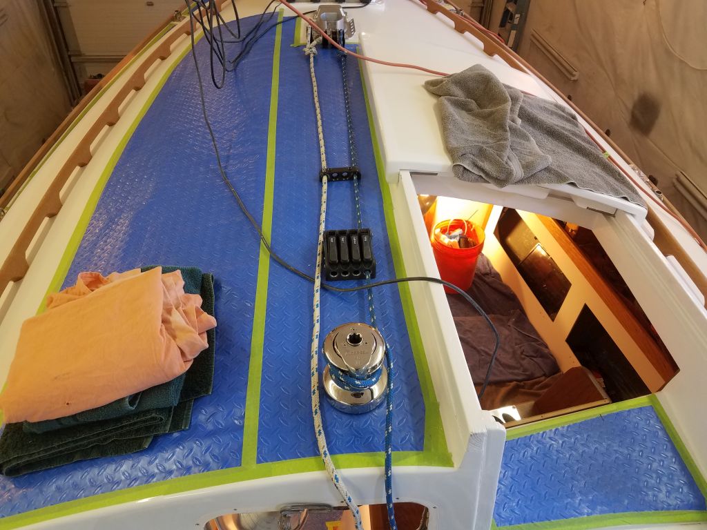
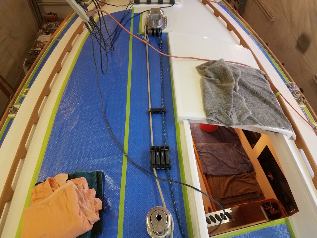
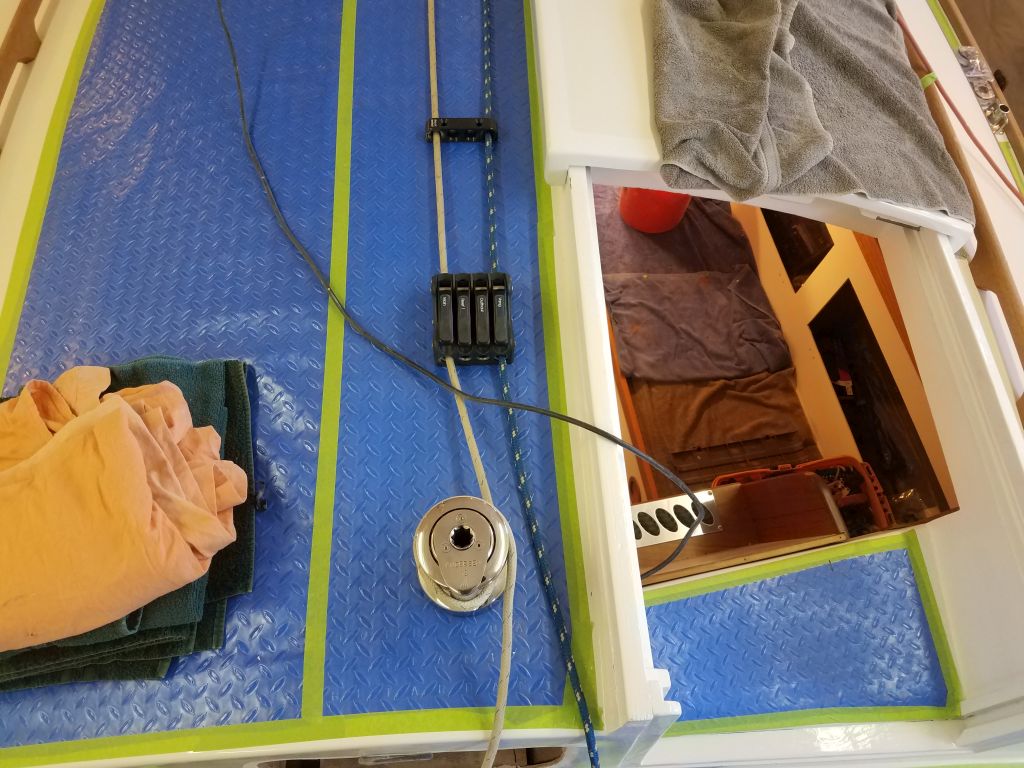
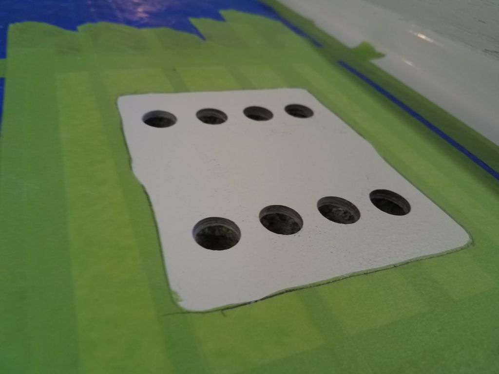
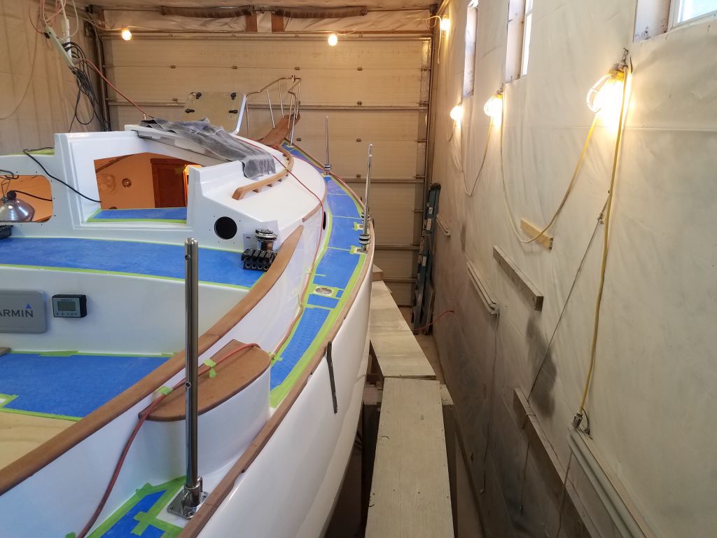
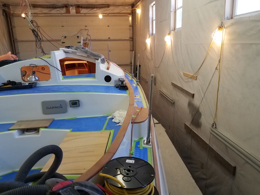
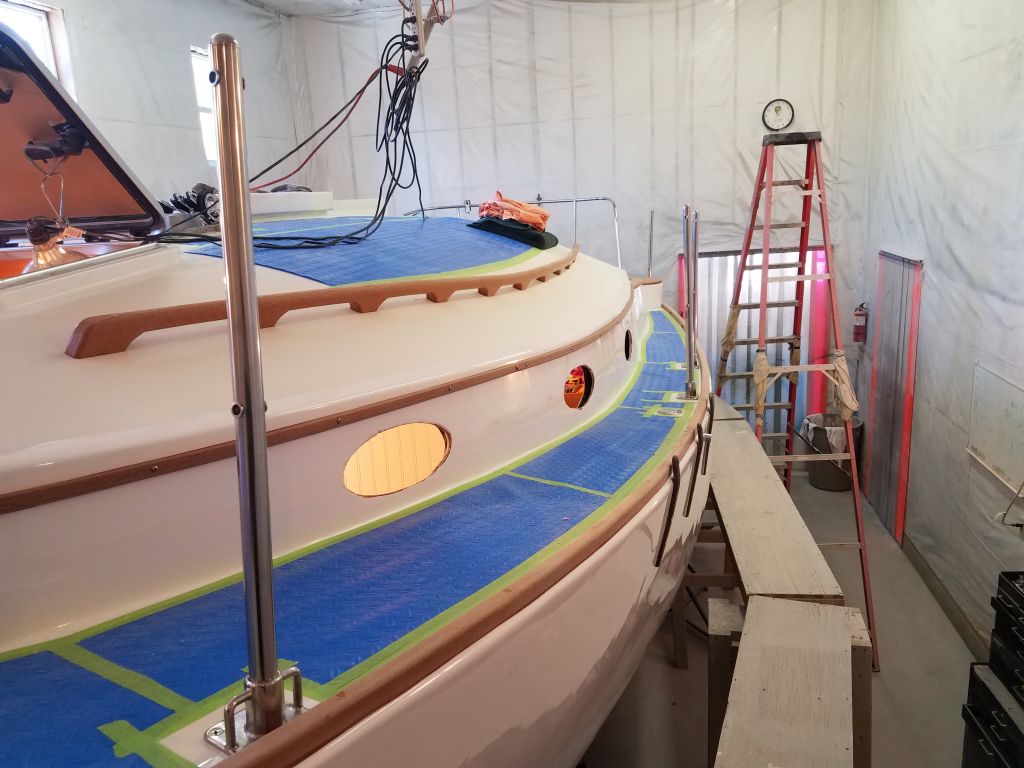
Next, I turned to the new deck hardware for leading some of the control lines aft from the mast to the cockpit. In all, there’d be four lines coming aft: main halyard; outhaul; reefing line; boom vang. The new mast organizer plate had plenty of room for the four turning blocks required at the mast base, and I installed these now so I could mock up the lines leading aft. It was a straight lead aft alongside the companionway, which greatly streamlined the overall installations ahead.
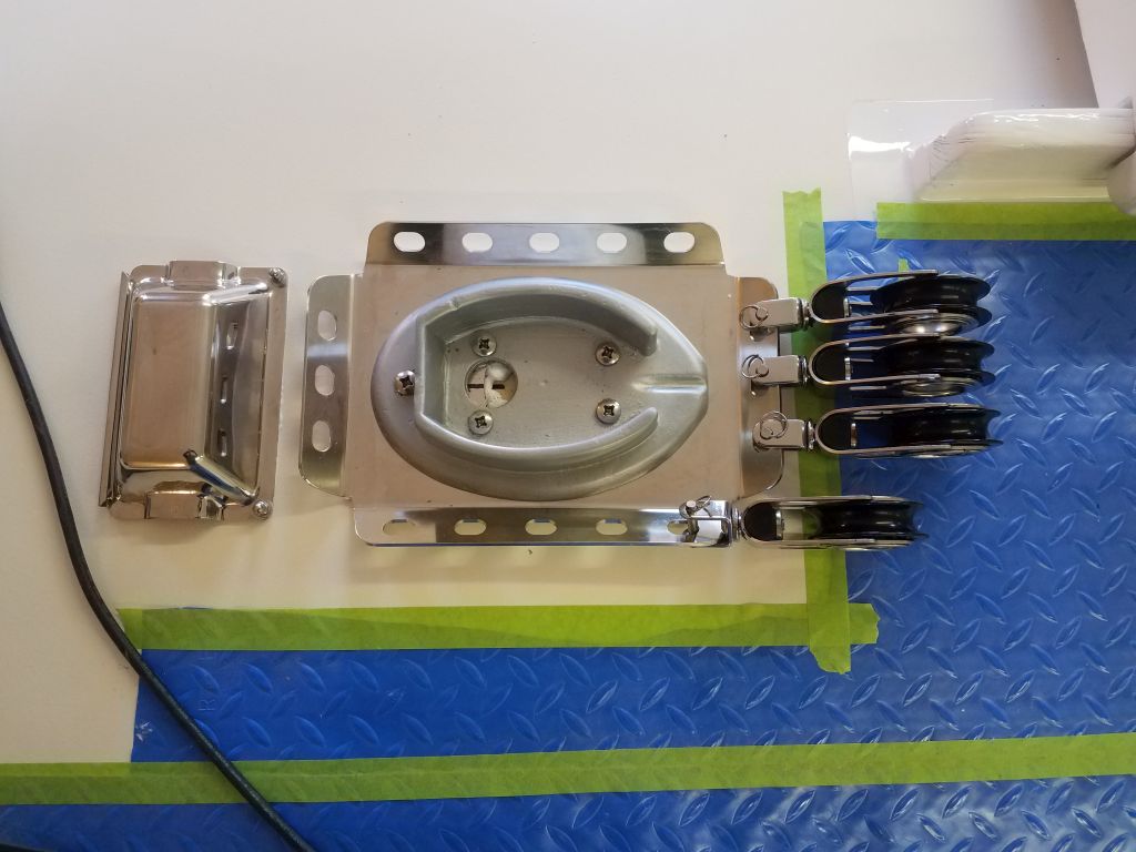
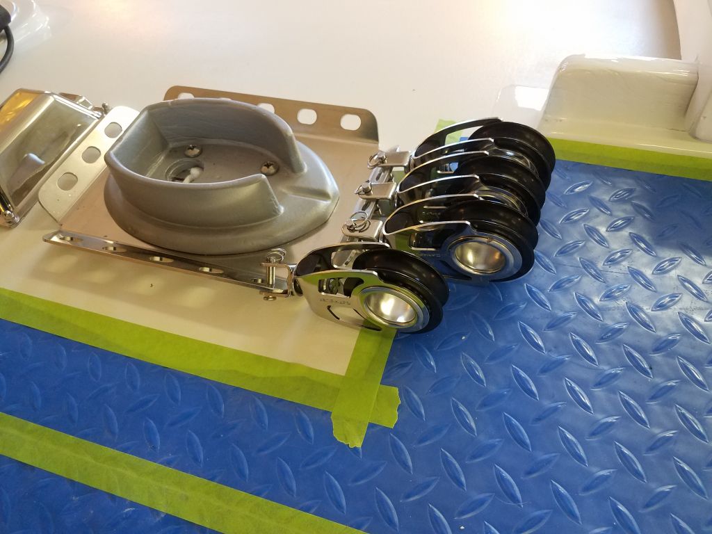
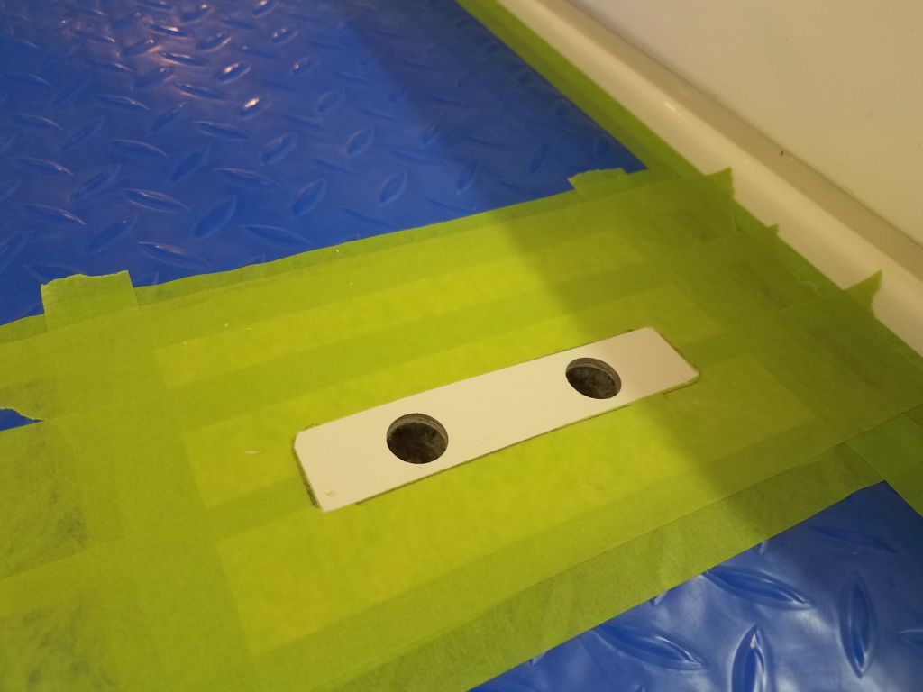
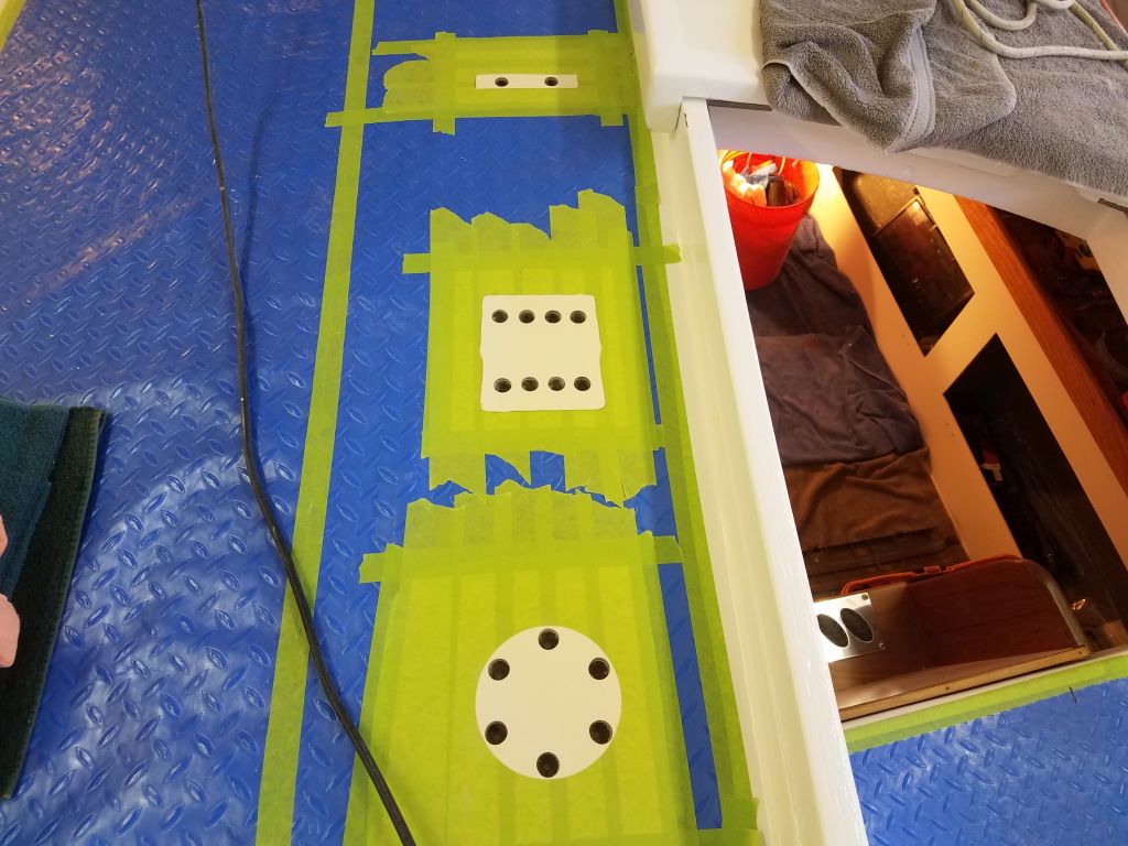
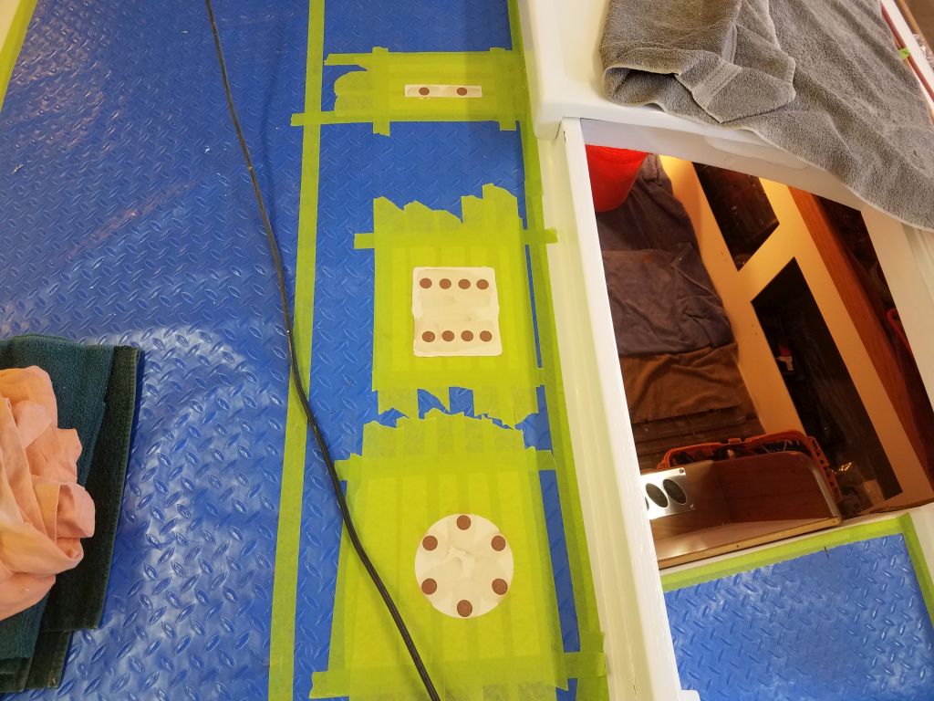
With a couple old shop lines standing in for the real things, I spent some time working out the final placement of a small 4-position fairlead, 4-position rope clutch, and a new self-tailing winch on the aft end of the cabin trunk, near the companionway opening. I wanted to locate the fairlead in such a way as to keep all four lines as straight as possible, though with the outlying main halyard block on the port side, the line would necessarily take a bit of an angle. But even so, the leads were straight enough to obviate any need for a fancy sheave-based deck organizer, allowing me to use the machined aluminum fairlead instead. The first line I’d used during early layout for the main halyard (the line to port) was too large to fit through the rope clutch, so later in the process I replaced it with a smaller line seen in some of the photos.

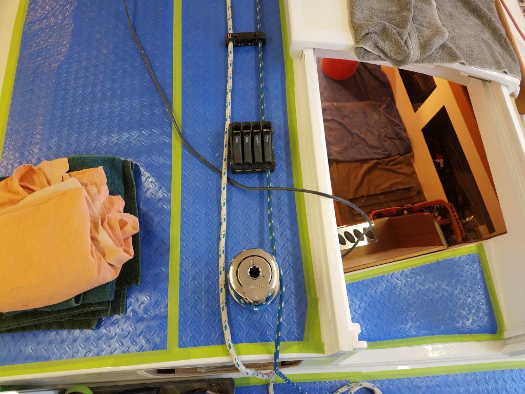
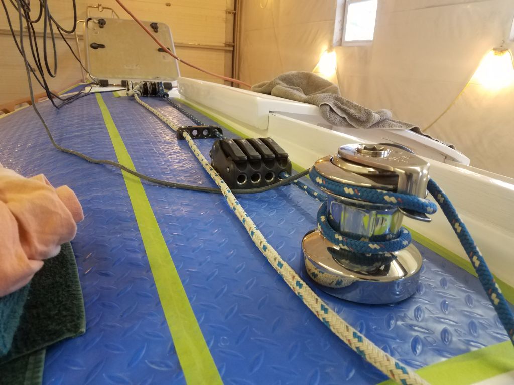

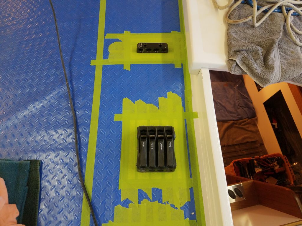
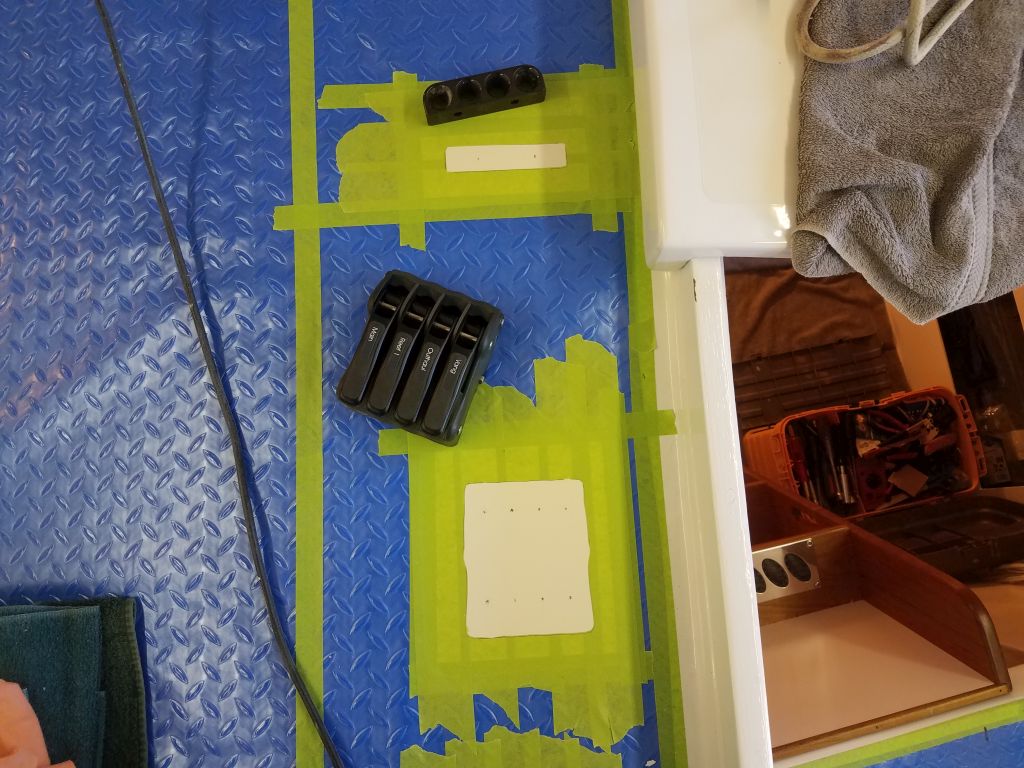
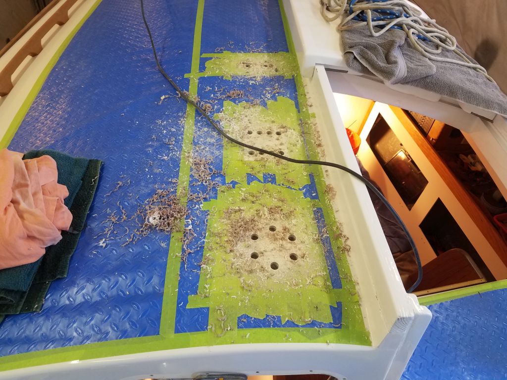
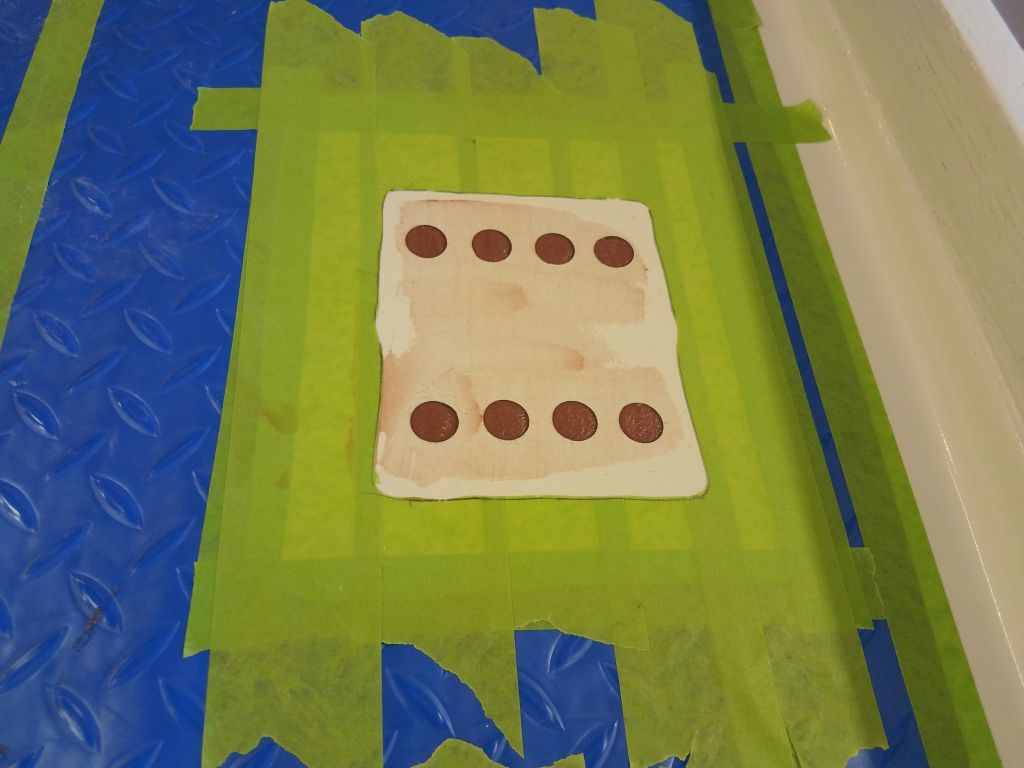
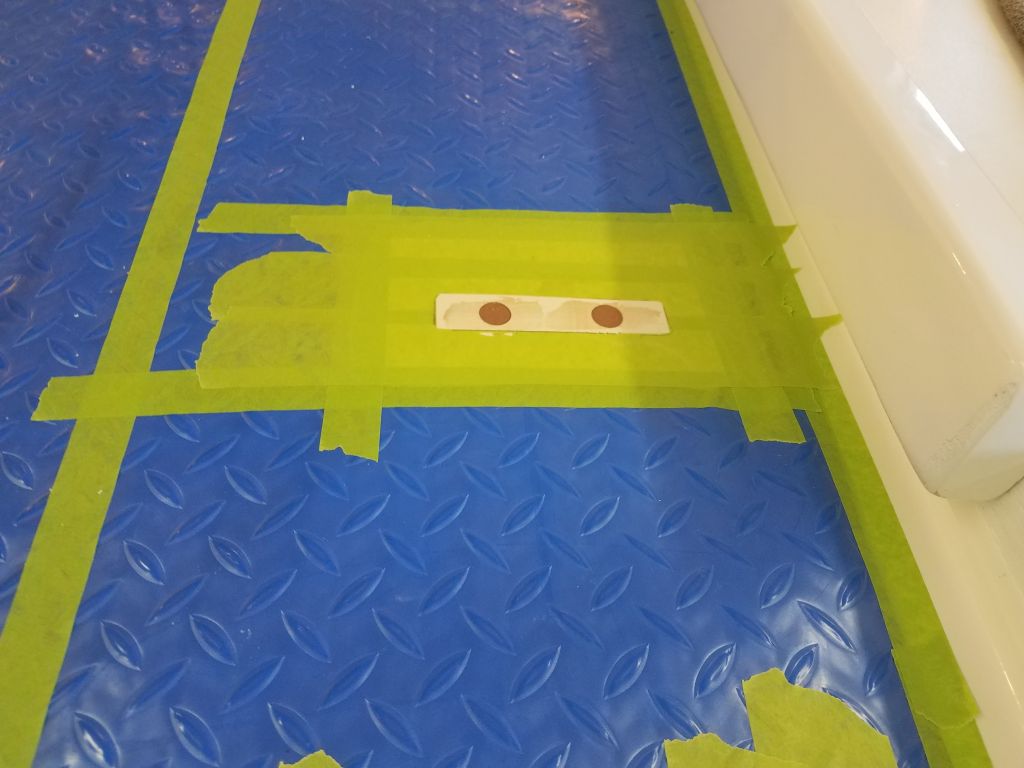
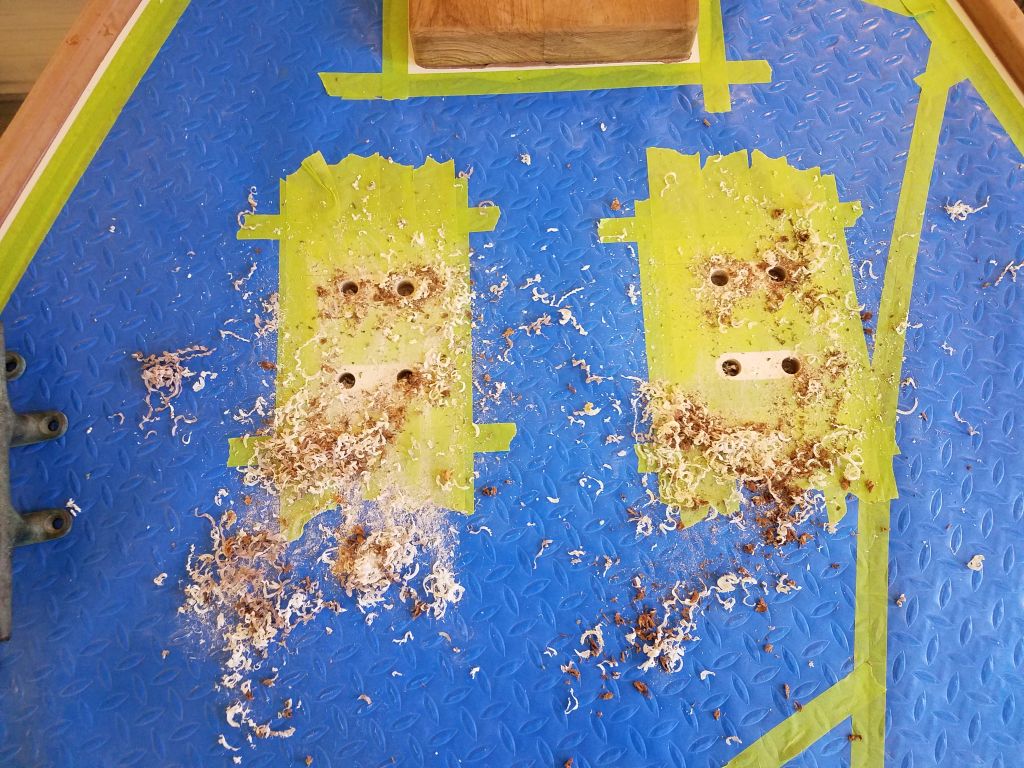
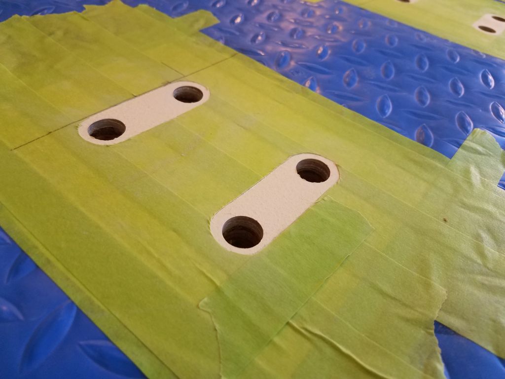
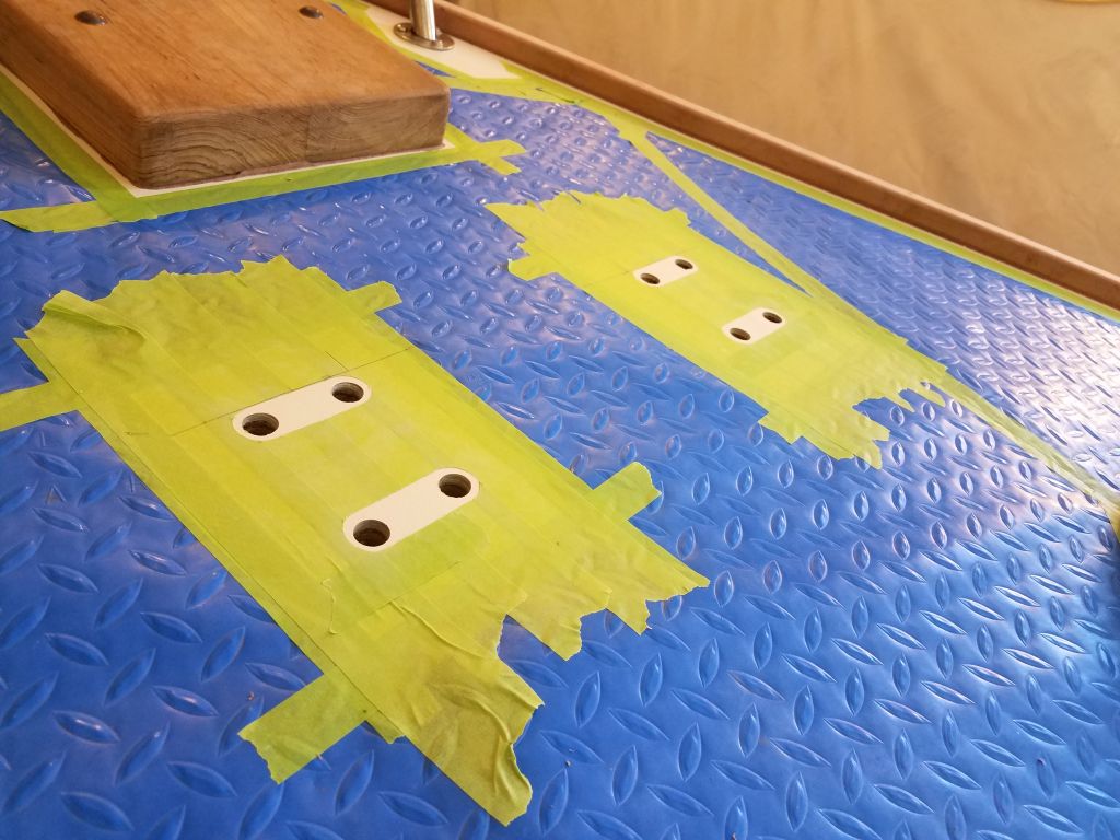
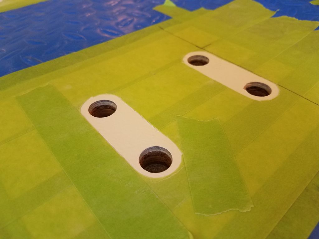
After a while, I finalized the positions of the three pieces of hardware, and after preparing the deck in each area by cutting away the plastic deck covering and replacing it with masking tape beneath each fixture, I relocated and marked the base positions of all the hardware, and marked the fastener locations. Then, with a 5/8″ Forstner bit, I removed the top laminate and coring from all the fastener locations, and, after cleaning up, filled the fastener holes with a thickened epoxy mixture in the usual way.


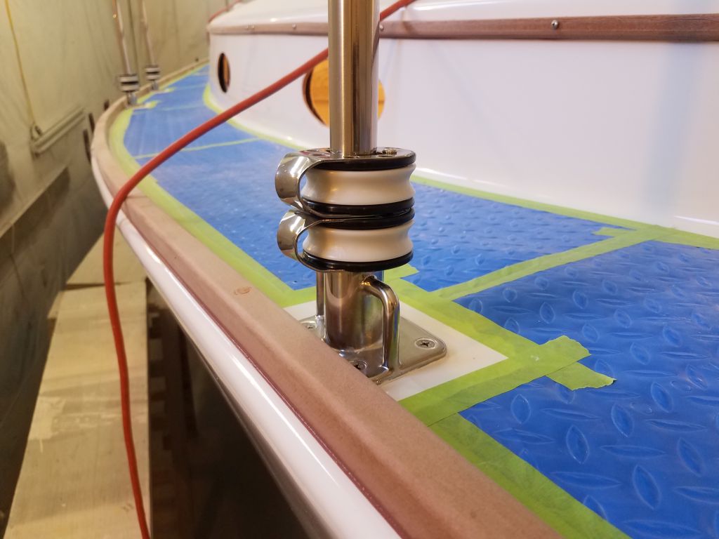
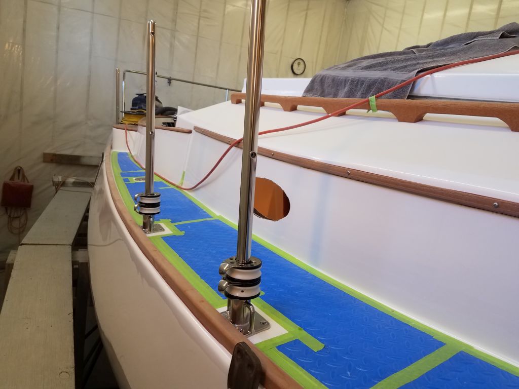
The pile of new stanchions on the aft deck was getting in the way, and with the bases all in place I could take a moment to clean out the little circle of now-cured sealant squeezeout within each base socket and install the stanchions with their setscrews. On the starboard side, I added two furler line lead blocks to each of the forwardmost three stanchions, as these had to be in place before the stanchion was installed in the socket. I’d already notified the riggers that the pulpits and stanchions were ready for them to come measure for new lifelines.

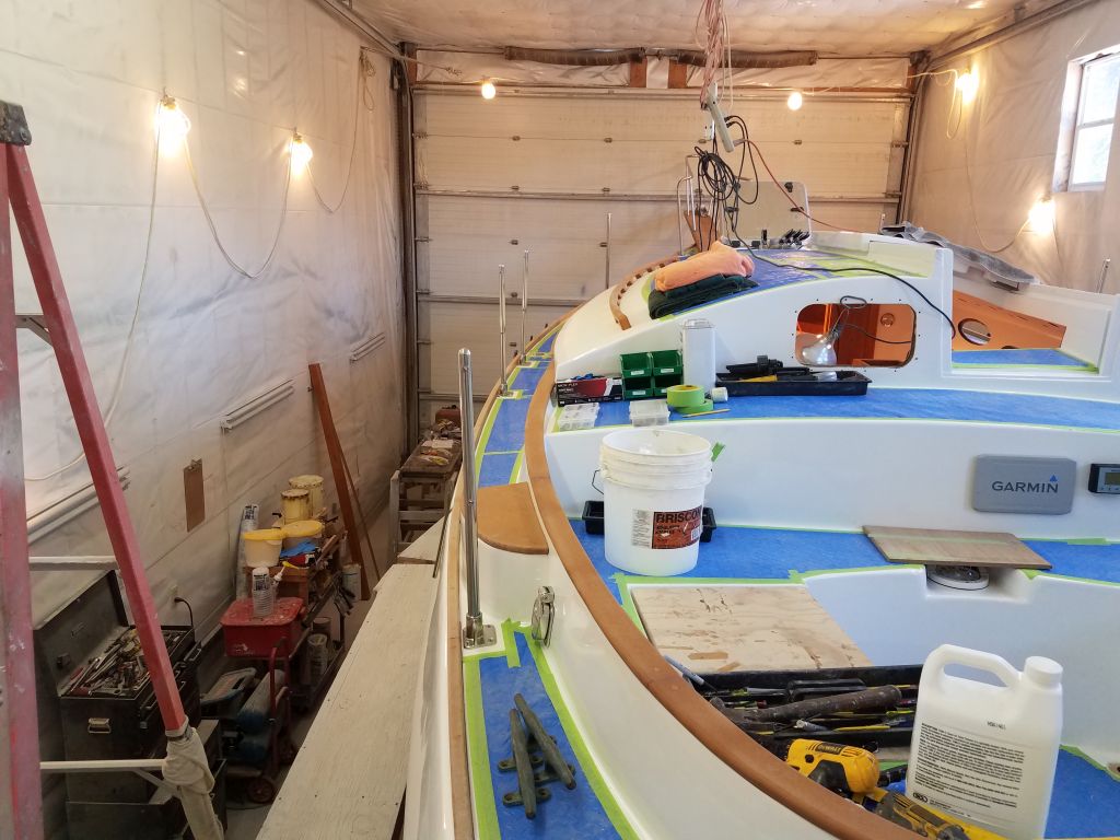
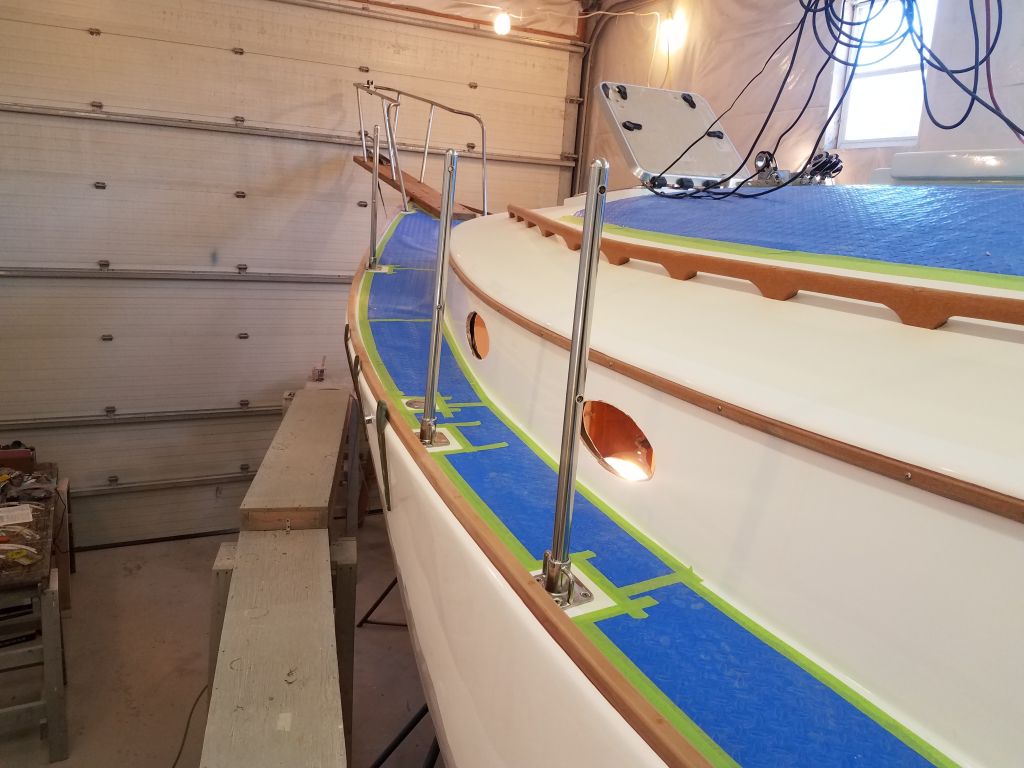
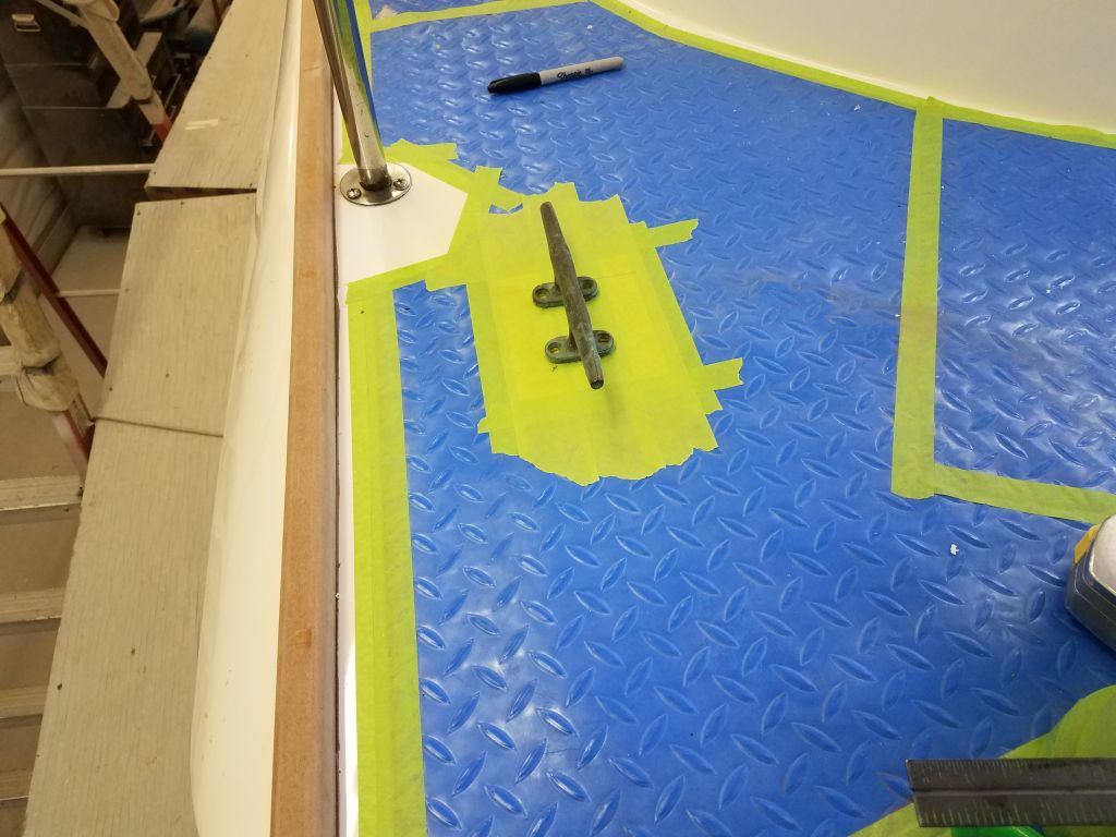
Continuing with hardware, I turned to the mooring cleats: two at the stern, two at the bow. Starting with photos of the boat as she’d arrived, I positioned the stern cleats in generally the same areas, though I made some minor adjustments as I deemed proper. In this case, the cleats ended up 6″ from the toerails, and 6″ aft of the forward stern pulpit bases. This location kept the cleats out of the way and the poop deck fairly clear, while still allowing a fair lead to the eventual stern chocks at the taffrail. As usual, I marked the holes and drilled out the deck core at each location. I planned to return later to fill the holes, but for now I continued with related hole prep.


On the foredeck, I determined the location of the bow mooring cleats, working roughly from an old photo, and went through the usual deck preparation and hole-drilling steps for these locations as well.

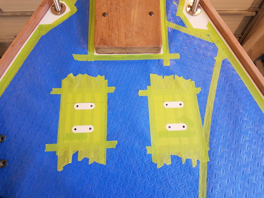
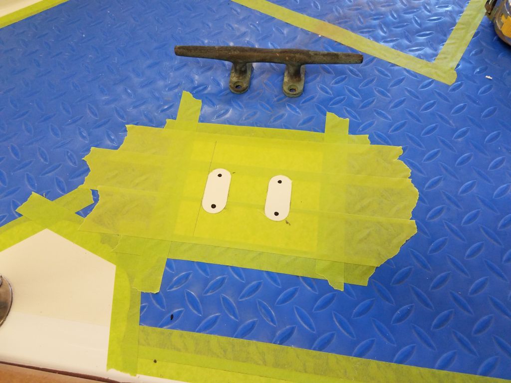
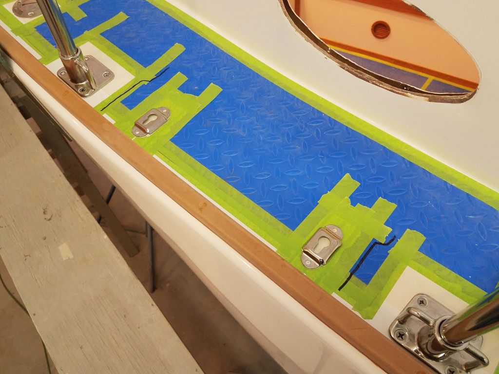
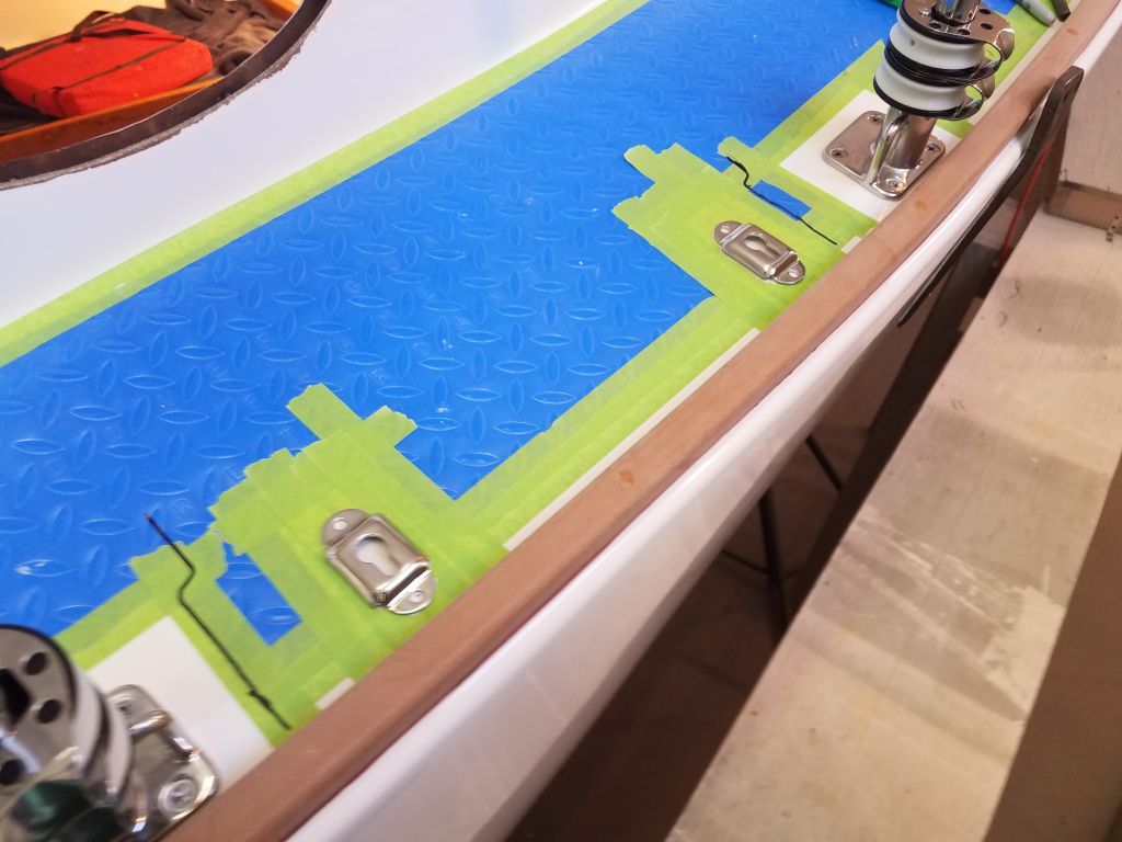
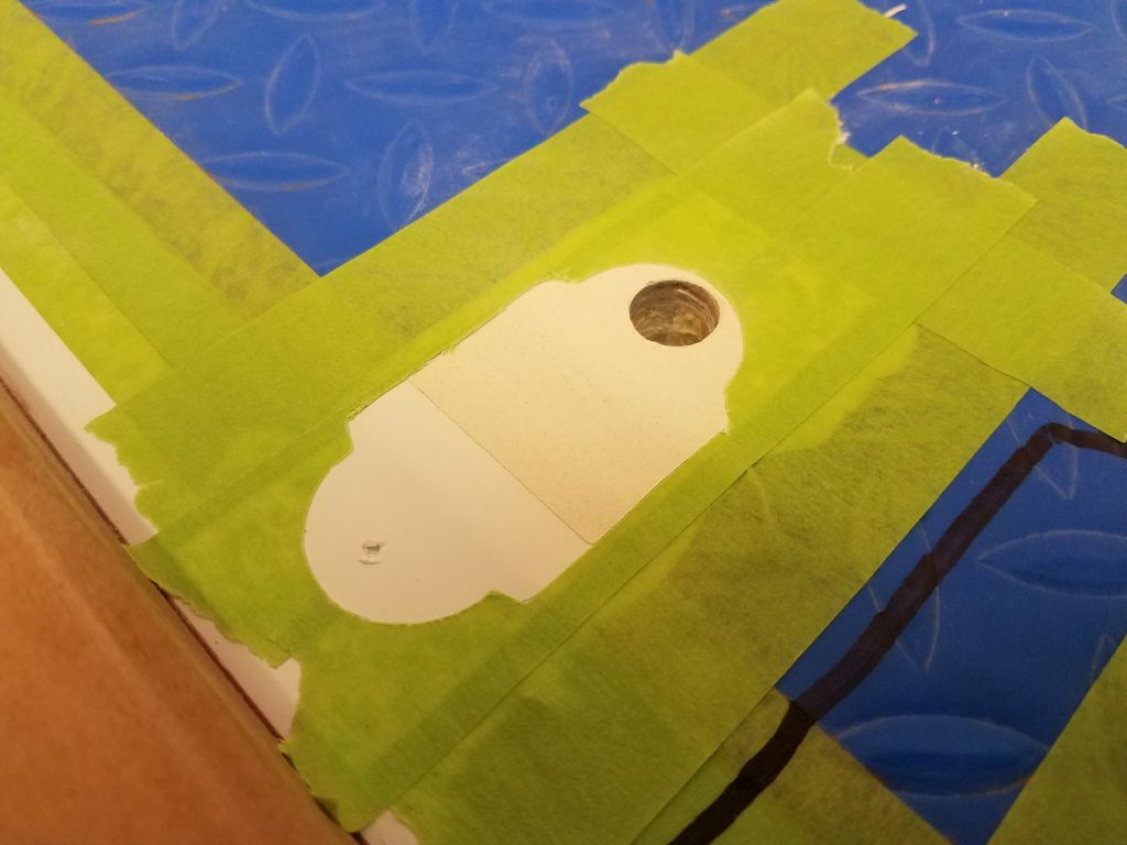
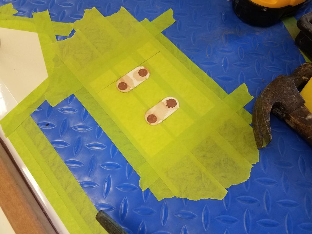
After lunch, I continued some hardware prep with mounting hardware for a portable boarding ladder the owner had sent. During earlier discussions we’d determined to place the ladder at the new lifeline gate opening amidships–with mounts on both sides of the boat–which was convenient and made sense for various reasons, including the opening gate; the relative flatness of the topsides there; and proximity to the after shrouds for a convenient handhold.
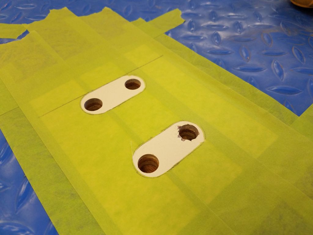
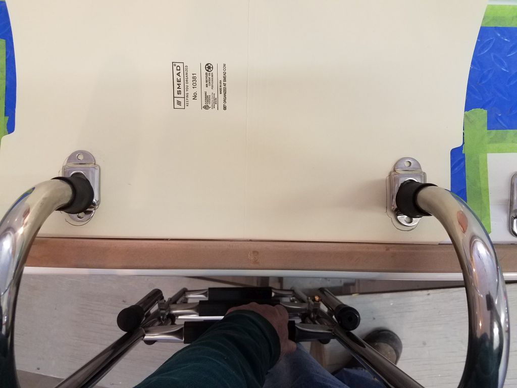
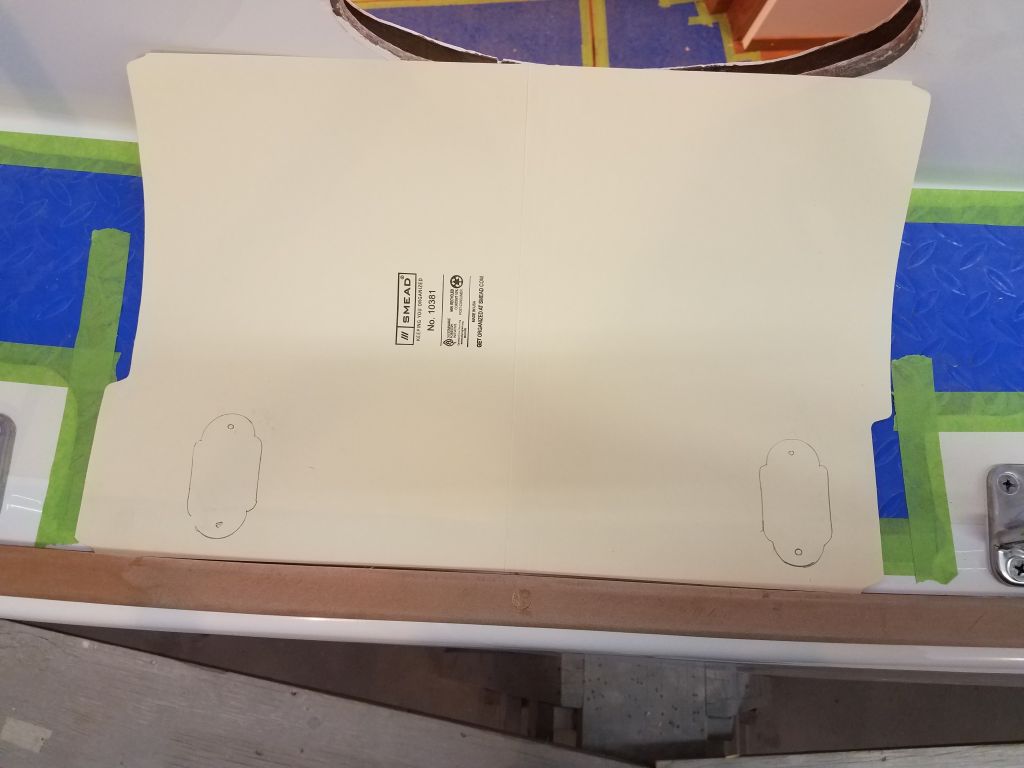
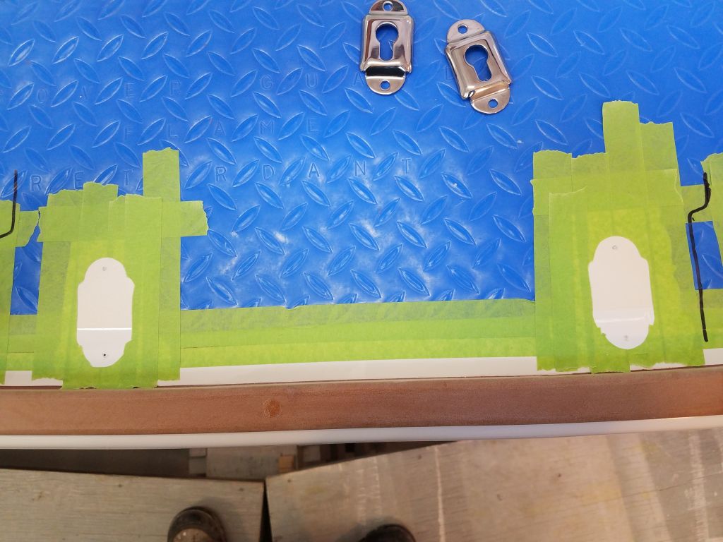
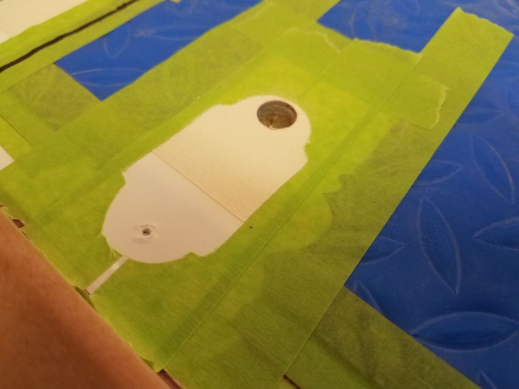
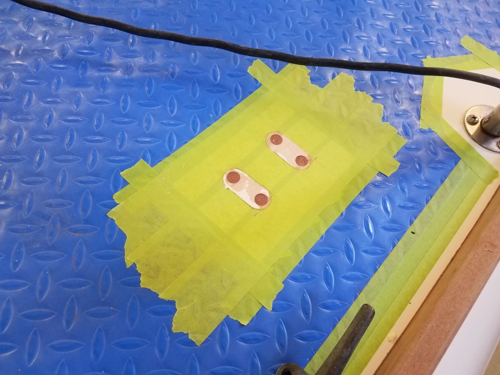
Placement of the keyhole-shaped mounts had to be precise to allow the ladder to work properly, so I installed a pair on the ladder and tightened the screws all the way so they wouldn’t move. Then, I used a file folder as a template to draw out the placement and make it easier to lay out and install the mounting hardware. In the photos, the ladder is a bit misaligned thanks to the challenges of holding it and photographing, but I’m sure they get the point across.
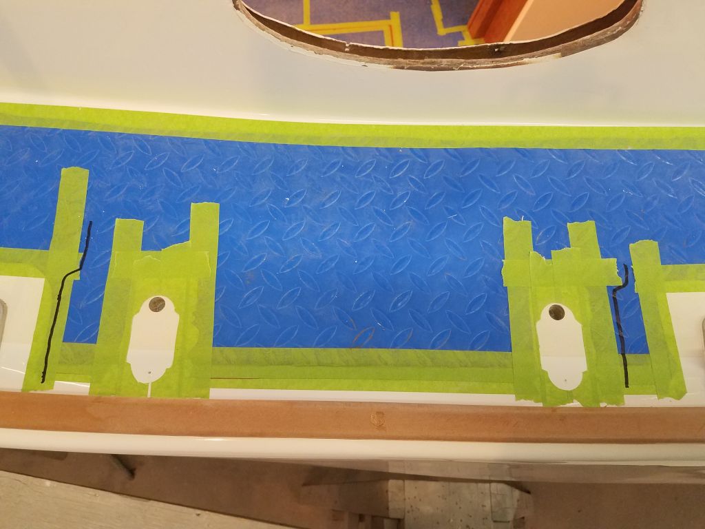
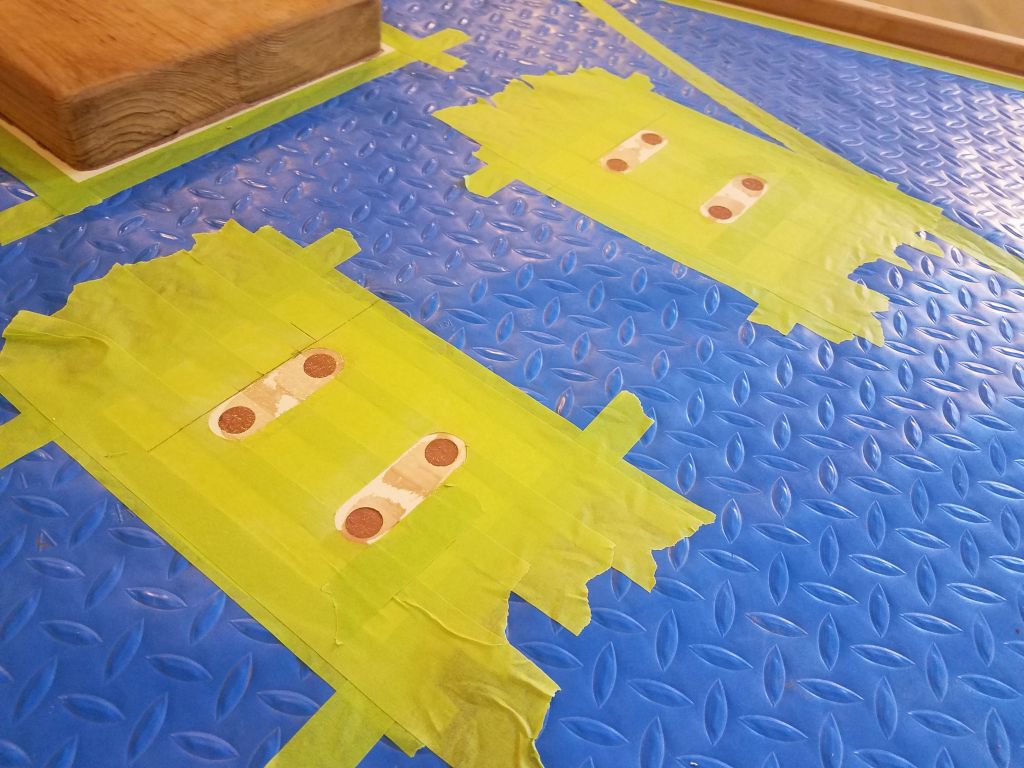
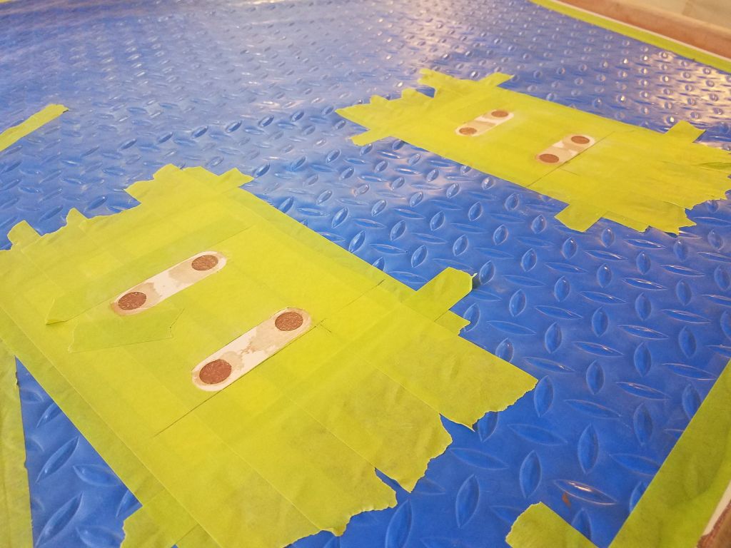
With the little template complete, I could align the file folder between the stanchion gates, then centerpoint the fastener locations to the deck to allow further marking and hole preparation–and easy to repeat on the opposite side of the boat.
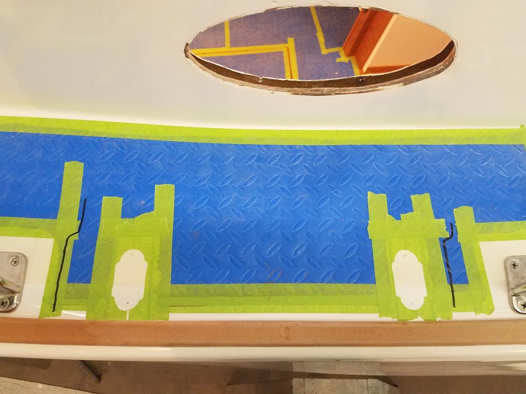
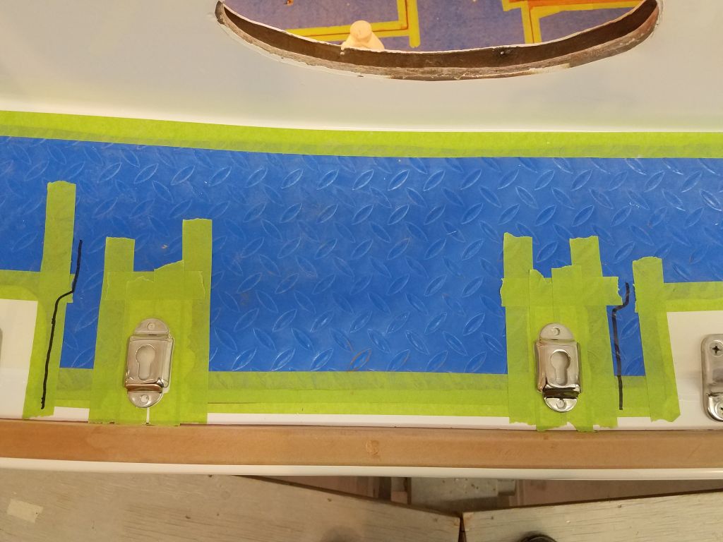

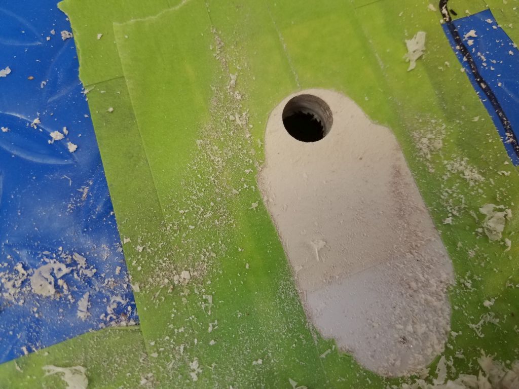
With the mounting locations all prepared, I drilled out the top laminate and core from the inner holes on the port side, where I knew there to be core material. On the starboard side, I should have remembered from my recent stanchion installations that the inner holes were also in solid fiberglass, but alas, only after I’d drilled a 1/2″ hole through the deck after expecting to find coring did I recall. Not to worry, as I just masked over the hole from beneath and filled it with epoxy along with those on the port side. The outboard holes on each side went through the solid fiberglass near the deck edge.
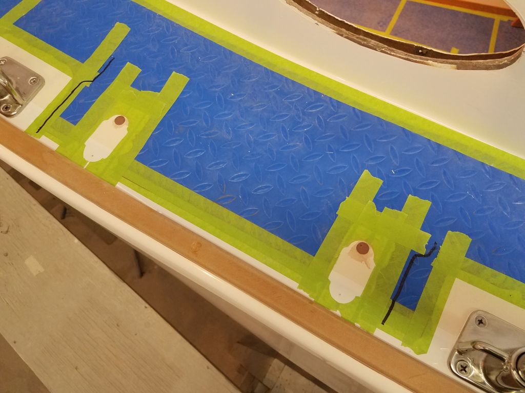

While I had the thickened epoxy going, I also filled all the new holes for the mooring cleats.
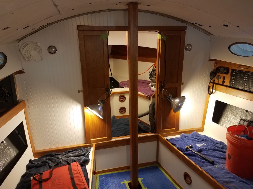
I’d been holding off on installing the compression post in the cabin because the interior was so much easier to move around without it, but inevitably the time did approach where it would need to go back in for good. Though I still planned to await installation as long as I could, I decided to get going on the final sizing and related prepwork, since I would also have to make a modification to the overhead panels to fit around the post.
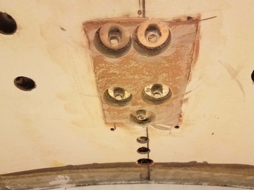
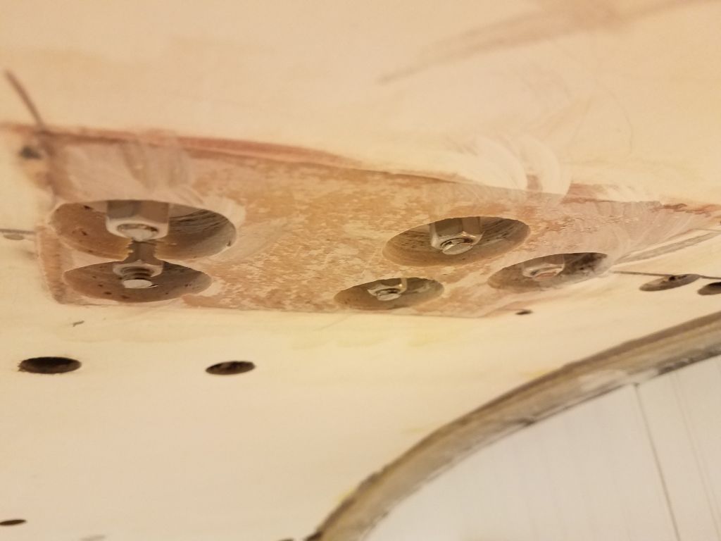
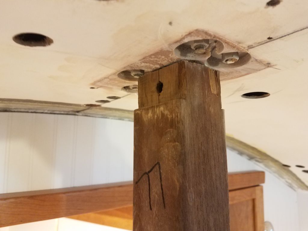
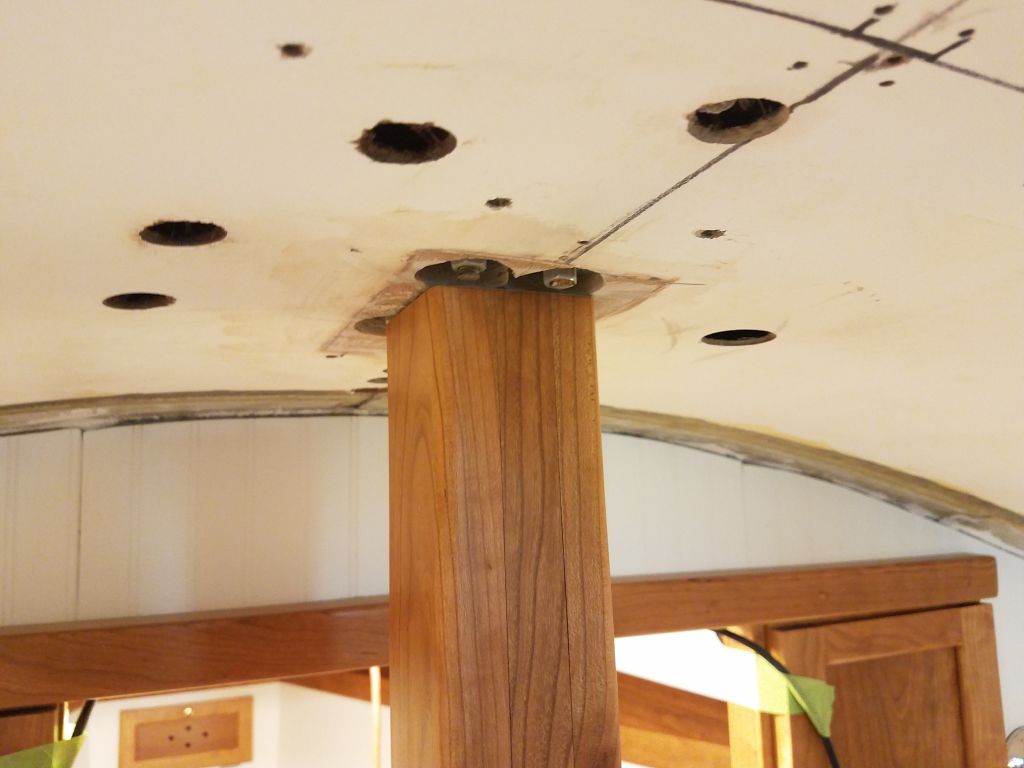
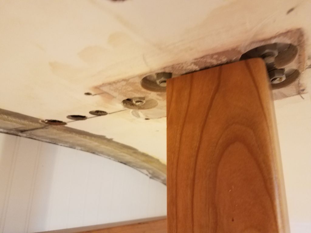
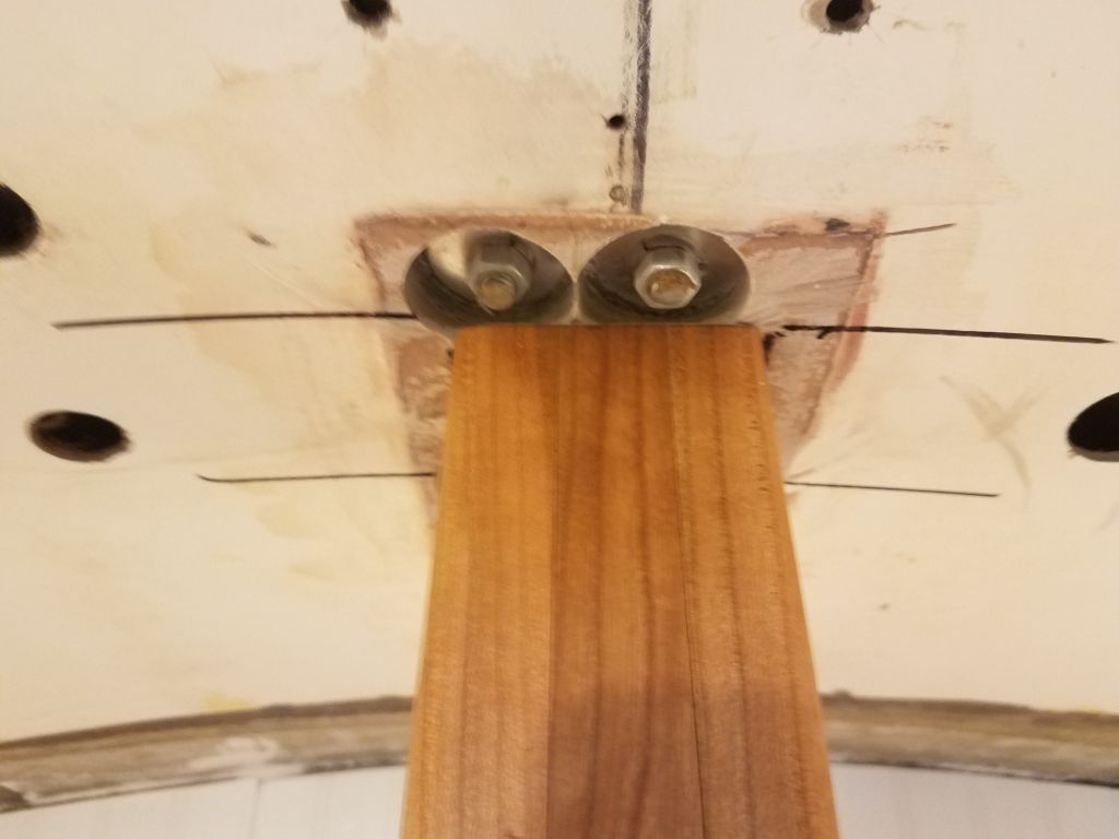
To begin, I cut off the excess bolt length from the bolts securing the mast step. These needed to be flush with the existing overhead. I cut these off with a grinder and a cutoff wheel, a task I really hate in a finished space; I covered the nearby settees and cabin sole with extra towels and blankets to catch (successfully) the red-hot bits of cutoff stainless.
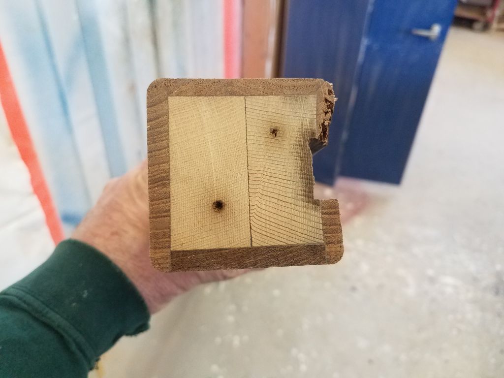
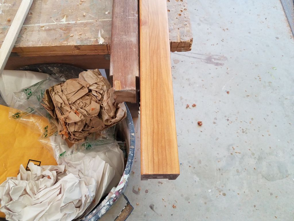
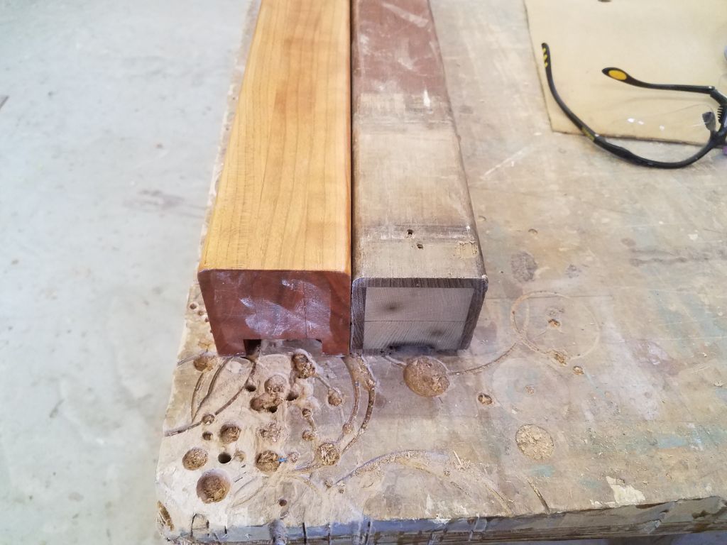
Using the old post as a mockup, and after a few measurements, I cut the old post to the length needed to fit. This took some trial fits and minor adjustments to get just right, as it had to be just so in order to slip into place yet come up tightly right beneath the mast step.. When I cut the bottom off the post, I was surprised to find that it was built of some other wood in the inside, with just 1/4″ teak wrapping ’round the edges.
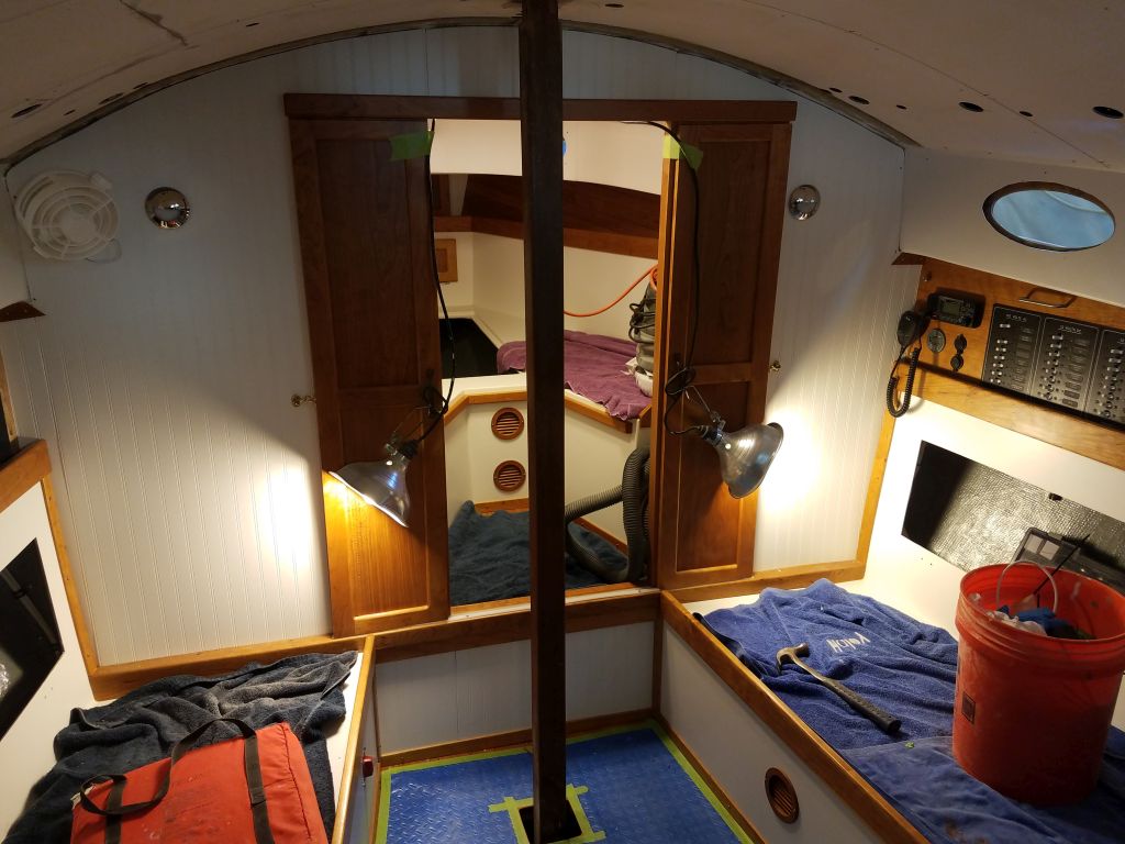
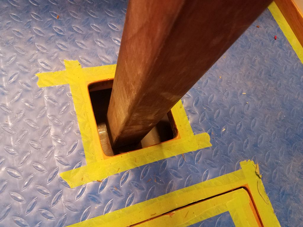
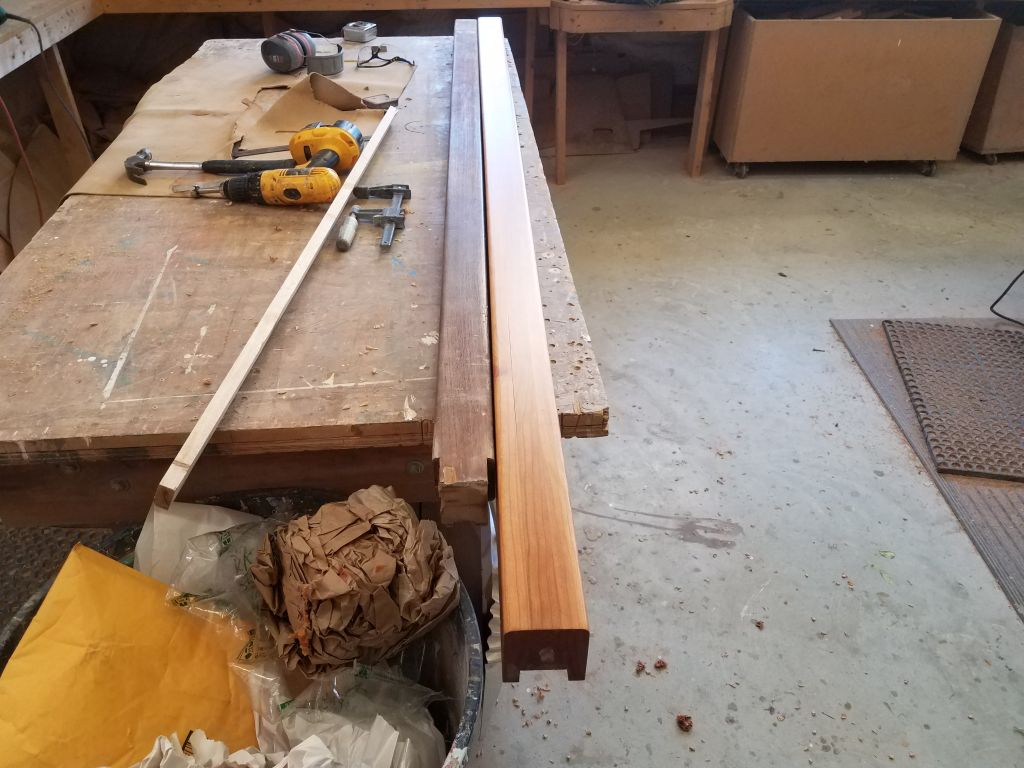
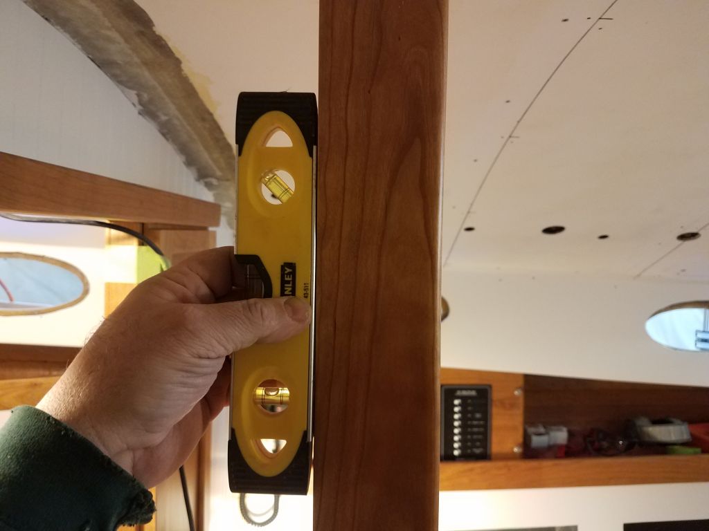
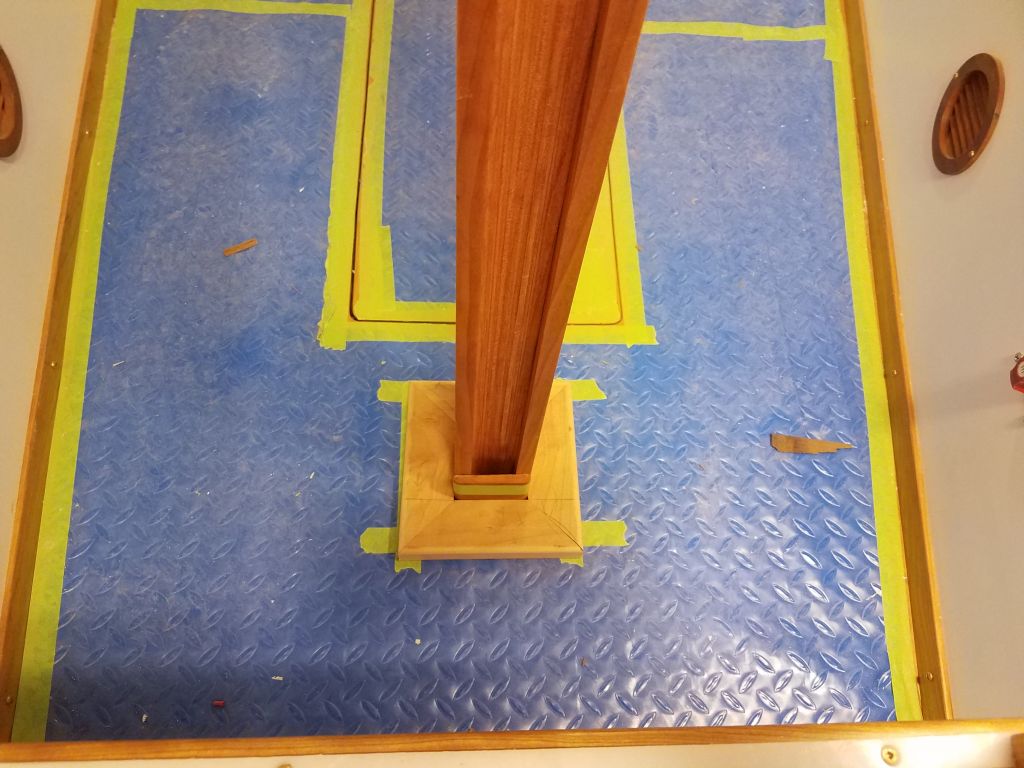
Satisfied with the length of the mockup (i.e. original post), I transferred the measurement to my new cherry post and cut it to fit. Then, I positioned it right below the mast step, and after levling the post in both directions made some reference marks on the overhead that I could use later to modify the plywood overhead panels to fit.

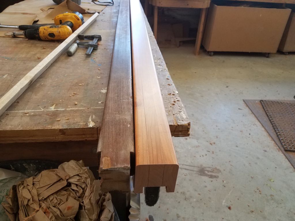
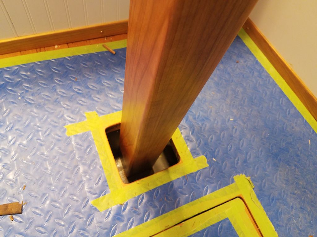

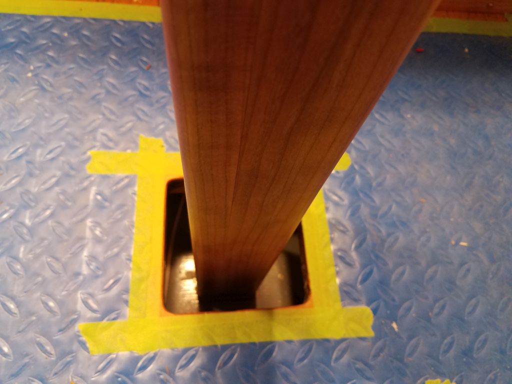
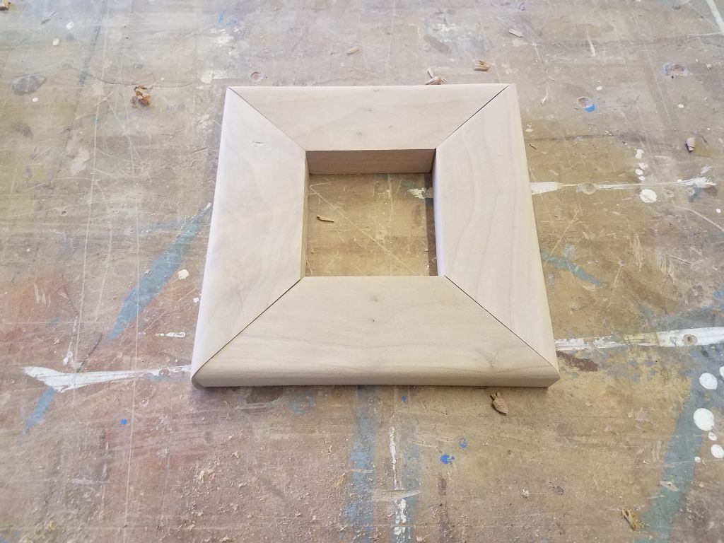
To keep the base of the post in place, I’d long ago abandoned the as-arrived idea of cleats at the very bottom of the post, where the bilge was basically inaccessible thanks to cabin sole supports and particulars of the bilge space itself, and the post simply rested on a new and strong piece of solid fiberglass I’d installed there much earlier in the project. Instead, I planned to use trim pieces at cabin sole level to align and position the post, as well as to cover the over-large hole I’d left in the sole. So with the post properly and plumb-ly positioned, I made up four pieces of mitered trim from 2″ wide, 7/8″ thick cherry to fit around the post, with ample overlap to screw to the cabin sole later.
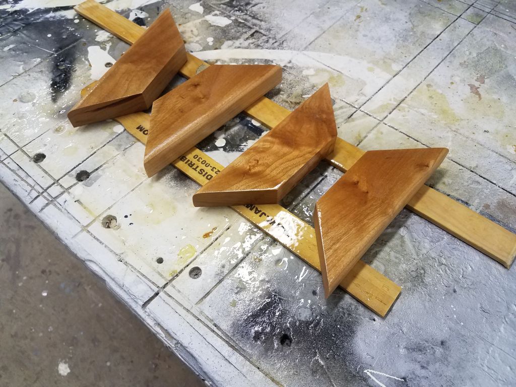
Once I’d rough-cut the pieces to fit, I sanded them clean and smooth, then began the varnish process. Meanwhile, for now I removed the post to await final installation as late as possible in the process.

Total time billed on this job today: 8 hours
0600 Weather Observation: 10°, clear. Forecast for the day: Sunny, 28°