

December 19, 2019
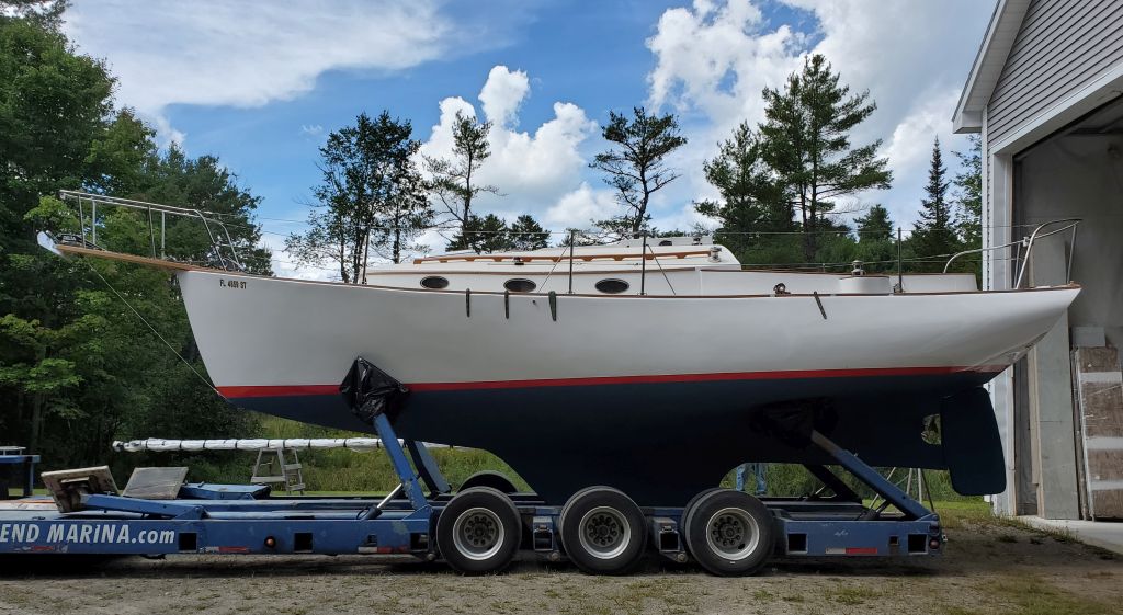
Scupper 206
Thursday
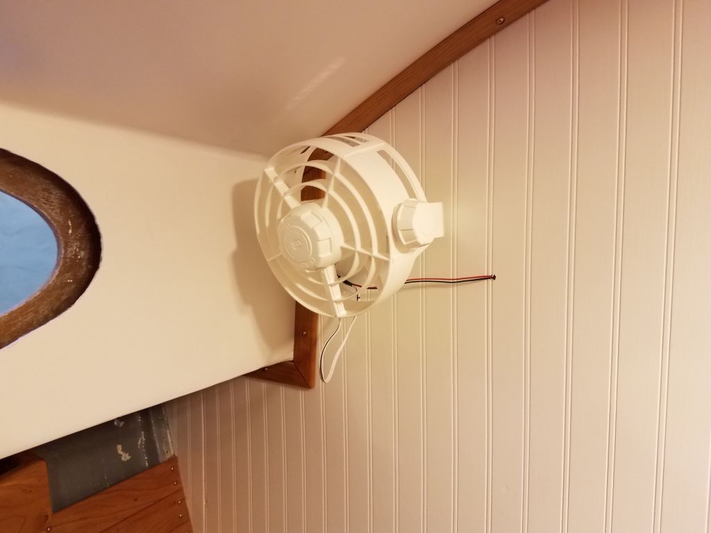
Working in the forward cabin, I continued with the second fan, which I located on the starboard side in the upper corner of the bulkhead (where it was near the wiring from the starboard bulkhead light in the main cabin), and secured the wiring for both appliances behind the trim at the edges of the bulkhead before leading it aft into the electrical locker. I found that a little butyl tape was handy for holding the little wires in the groove behind the trim. As with the port side, I’d make a piece of trim to cover the exposed wiring on the bulkhead in the near future.
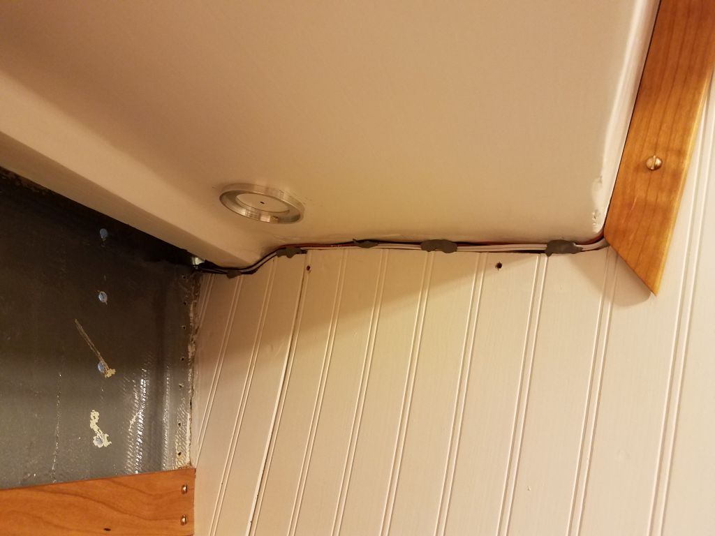


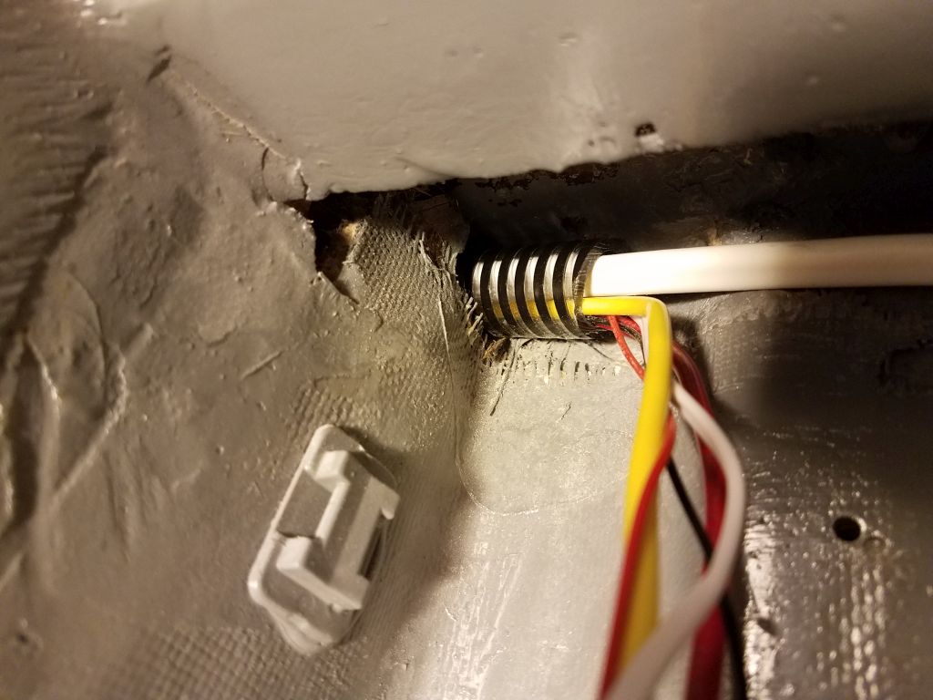
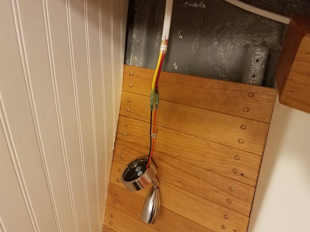
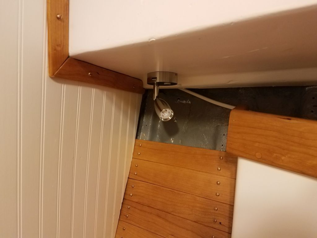
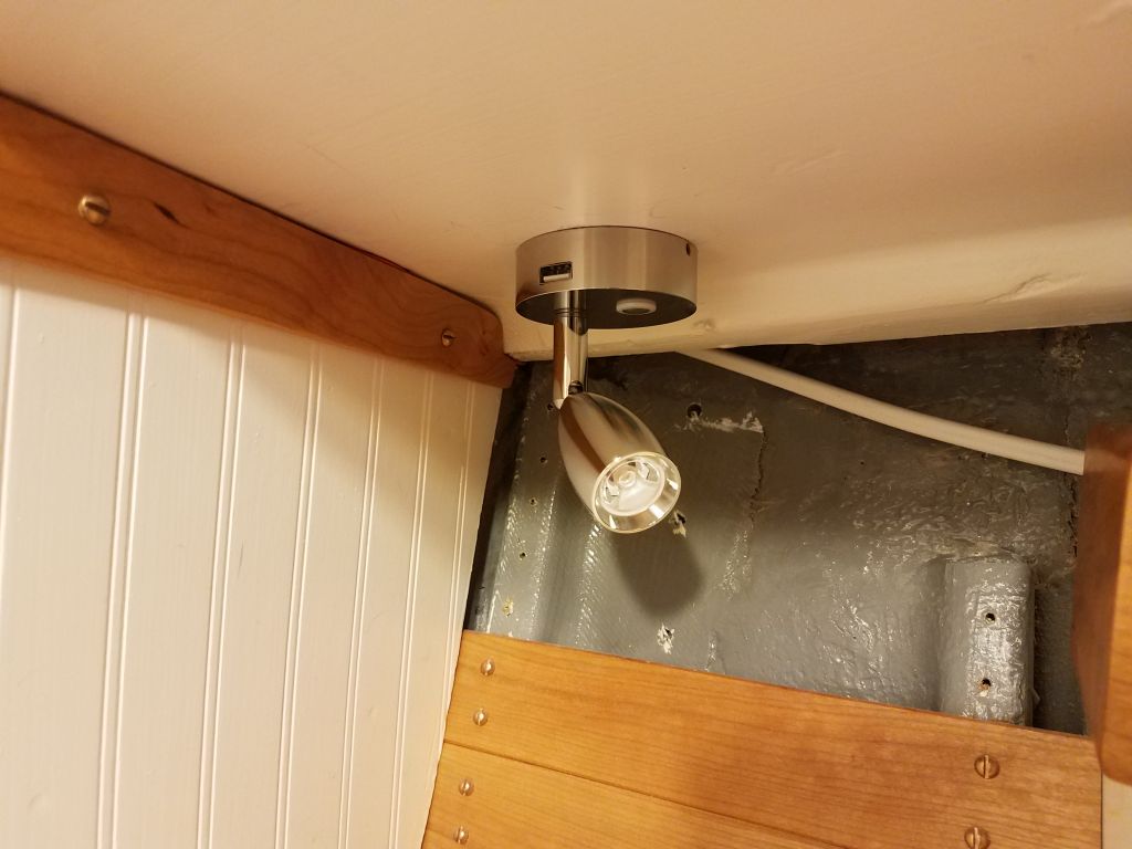
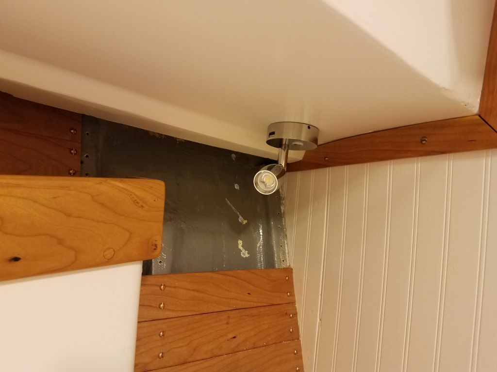
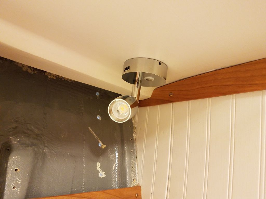
After considering and rejecting various locations, and taking into account the owner’s wishes and the physical requirements of the spaces, I eventually installed the two small berth lights (one per side) under the sidedecks just aft of the berths, where there was open space, relatively convenient for hidden wiring, and to keep the lights out of the way. These lights also incorporated built-in USP ports, and swiveled in all directions. On both sides, I was able to run the wiring the short distance beneath the liner and then aft to the main wiring areas. Note that those top few ceiling boards on both sides will be replaced as soon as I finish the wiring and install the forward chainplates.
I had hoped to begin installing the underdeck secondary lighting, i.e. LED strips, as I’d recently received all the materials I thought I needed, but I found that the diffuser covers I’d selected didn’t work with the LED strips that I had, so I spent a little time sourcing replacement diffusers and would await installation till another day.
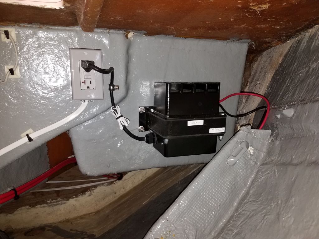
Instead, I turned to the battery chargers again, and in the forward cabin, armed with new supplies, I installed an outlet box, wired in the AC outlet, and finished the charger installation. After discussion, the owner had decided not to install the poorly-executed indicator lamp that came with the charger, since it would have been an eyesore and the digital battery monitor would provide all the salient information anyway. Once I’d finalized the battery box and house battery location, I could run the charging wires from the charger to the box, but for now left them coiled aside.
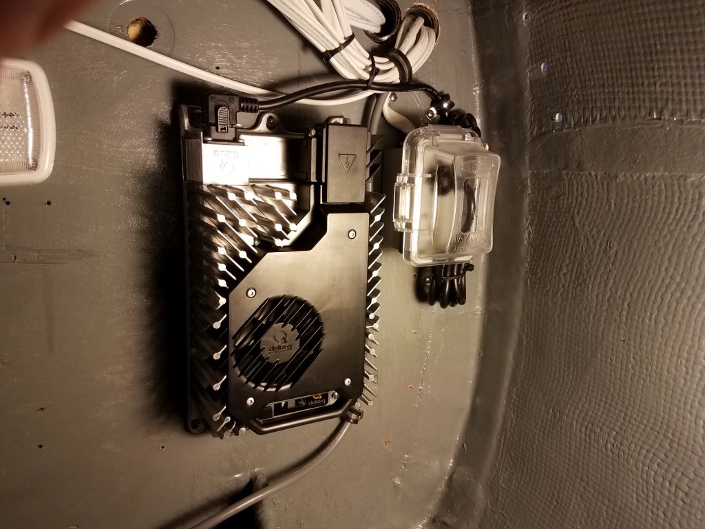
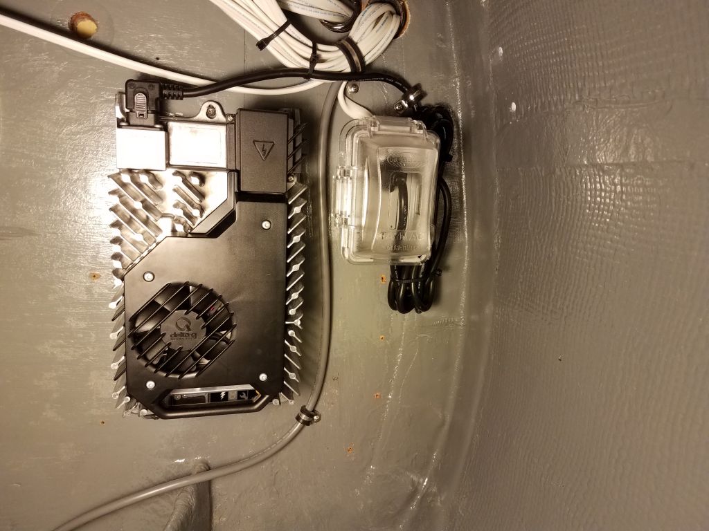
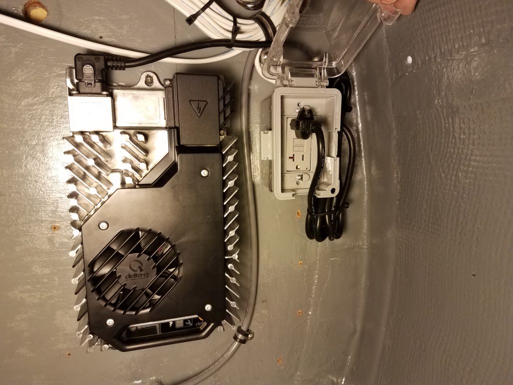
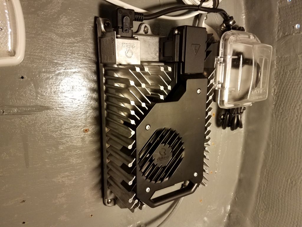
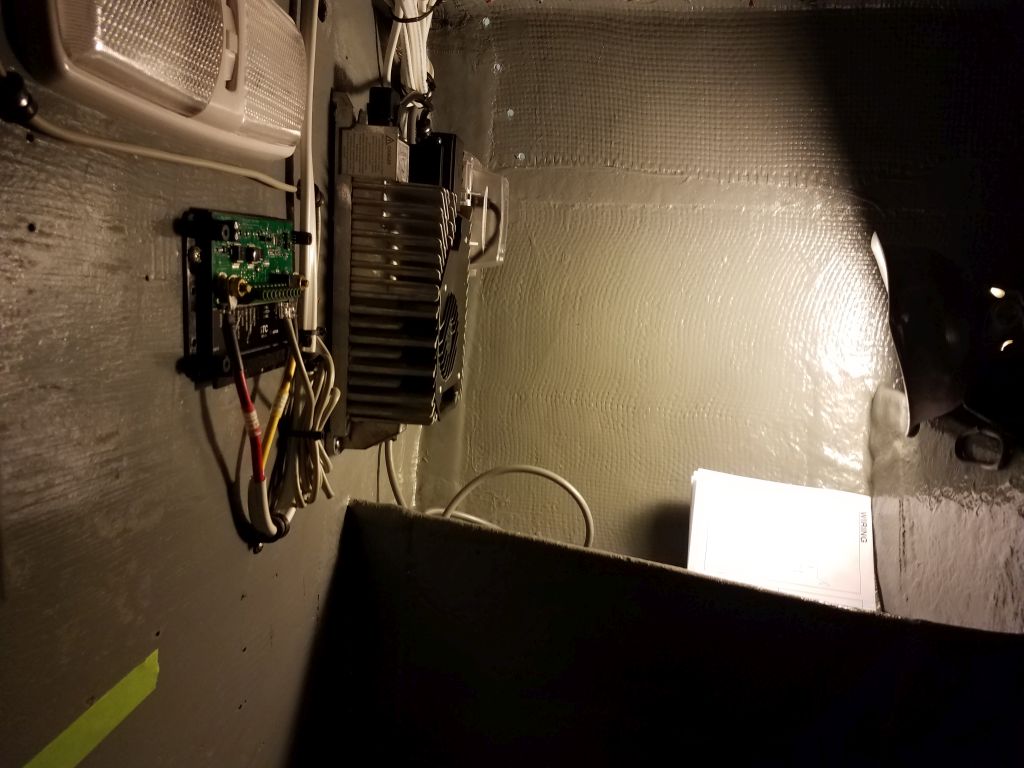
The 48-volt charger for the electric motor power supply was a different manufacturer and design, and was easier to handle and install. I chose a location on the starboard engine room bulkhead that was out of the way yet accessible, and left room for an outlet box for the 110-volt supply to the charger. On this outlet, I added an external cover to protect the plug, and secured the generous excess power cord out of the way next to the box. Once the engine batteries were in place, I’d complete the charger wiring, which would include a temperature sensor along with the charging wires.
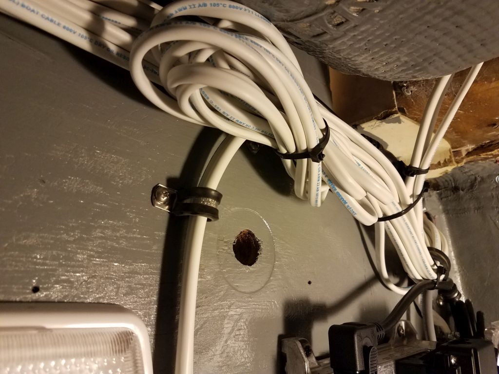
For future expansion, I’d run one extra circuit aft into the engine room, and now I coiled up and secured this excess cable.
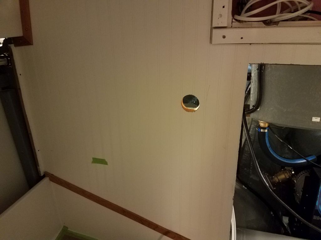
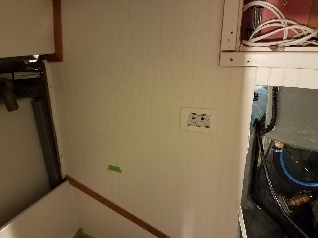
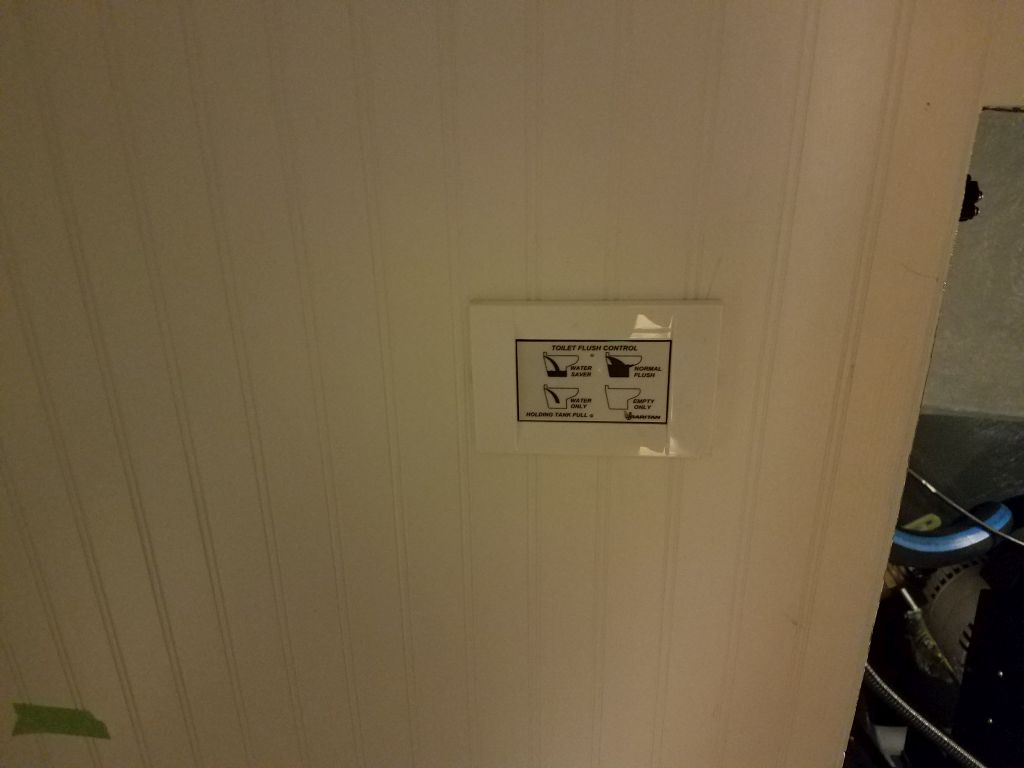
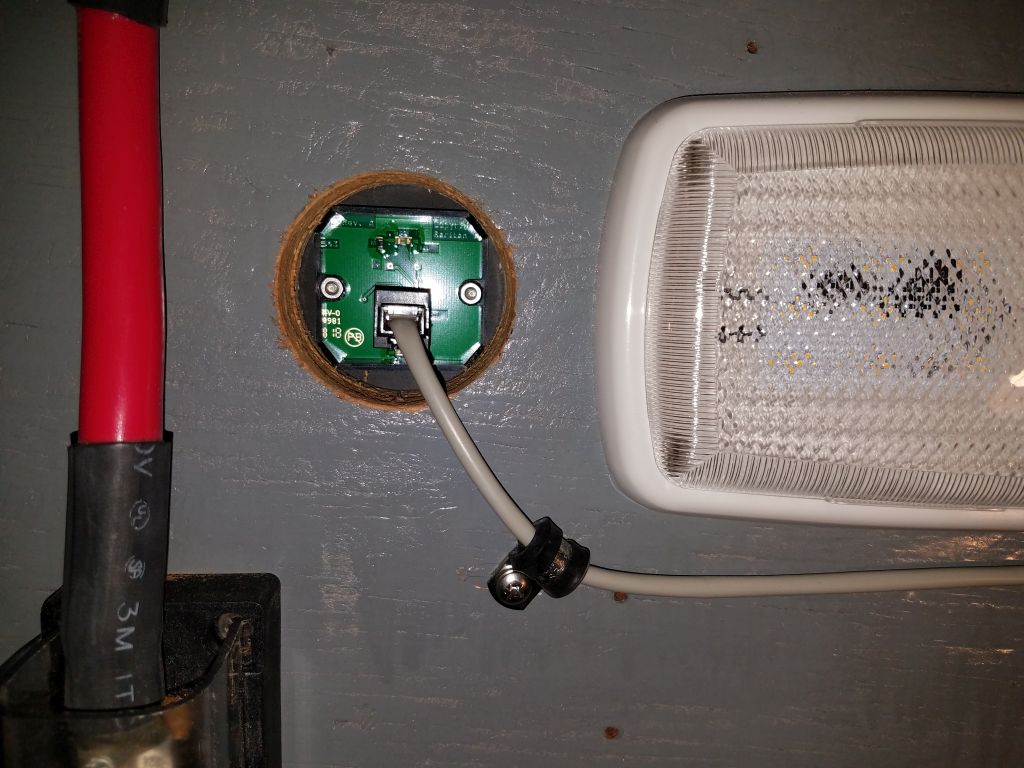
It made sense to continue in the engine room and finish up what was needed to terminate and secure the remaining few wires, starting with the large 8AWG wire pair required for the electric head controller. With all components of this system now on hand (the toilet itself had been backordered for a couple weeks), I felt ready to begin the installation, starting with the small control panel in the head itself. After confirming measurements of the throne, and working within existing limitations of the space and the opposite side of the bulkhead, I chose a location for the control and drilled the large hole required for its installation, then installed the panel and its Ethernet cable that would connect it to the control box.
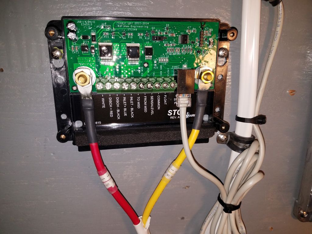
Next, I chose a location for the control/wiring box, keeping it out of the way of the eventual battery boxes yet close and convenient to the main wiring. With the box in place, I could terminate and connect the main power cables, and also the Ethernet cable from the control panel. There were a few additional wires required that would run between this control box and the toilet itself, and I’d continue installing these wires next time, but for now the day was done.
Total time billed on this job today: 8.25 hours
0600 Weather Observation: 14°, mostly clear. Forecast for the day: Sunny, windy, 17°