


March 19, 2021
Lyra 41
Thursday
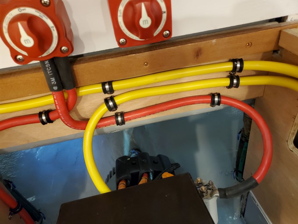
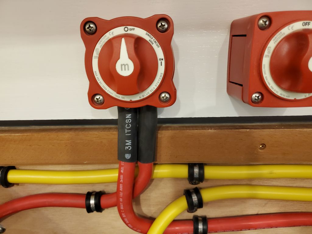
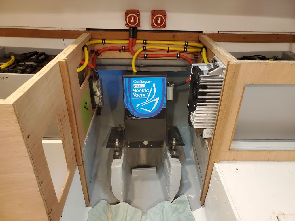
Other business kept me away from the shop till after lunch, but during the afternoon I finished up the rest of the heavy battery cables required for the electric motor. Now that the aft bulkhead was painted and cured, I could start by installing a pair of battery switches above the engine room: One for the motor, the other for the house bank. These two switches were the same model, but there were slight differences in their housings. To hold the rear housings in place while allowing removal and installation of the front part of the switch, I added a pair of small screws through the back of the housings. I installed the switches clear above, but close to, the top of the countertop, and later planned to modify the countertop section to slide past these and the house battery cables.
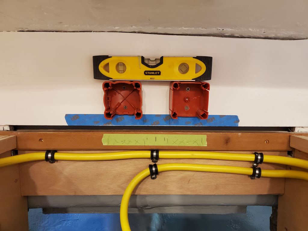
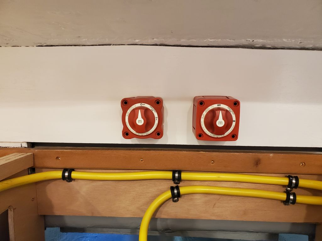
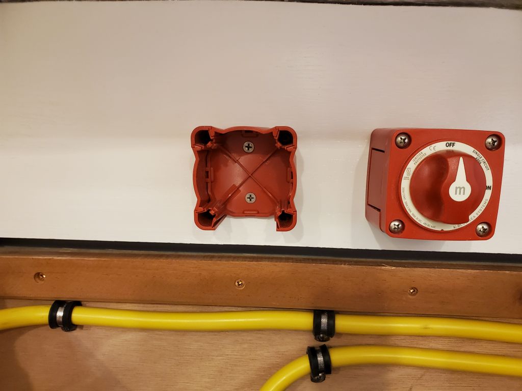
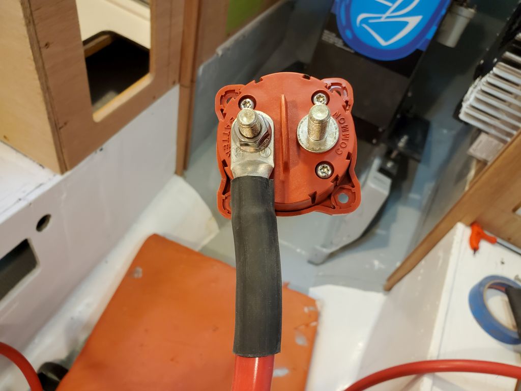
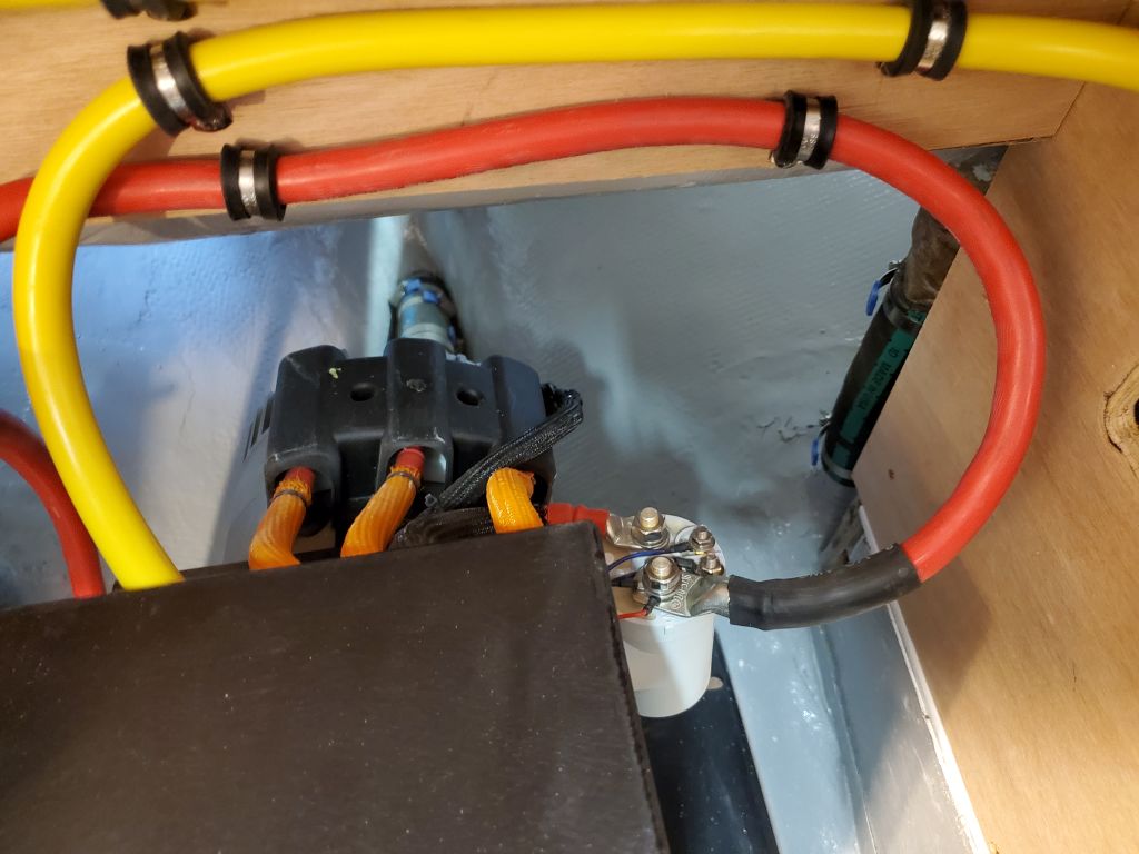
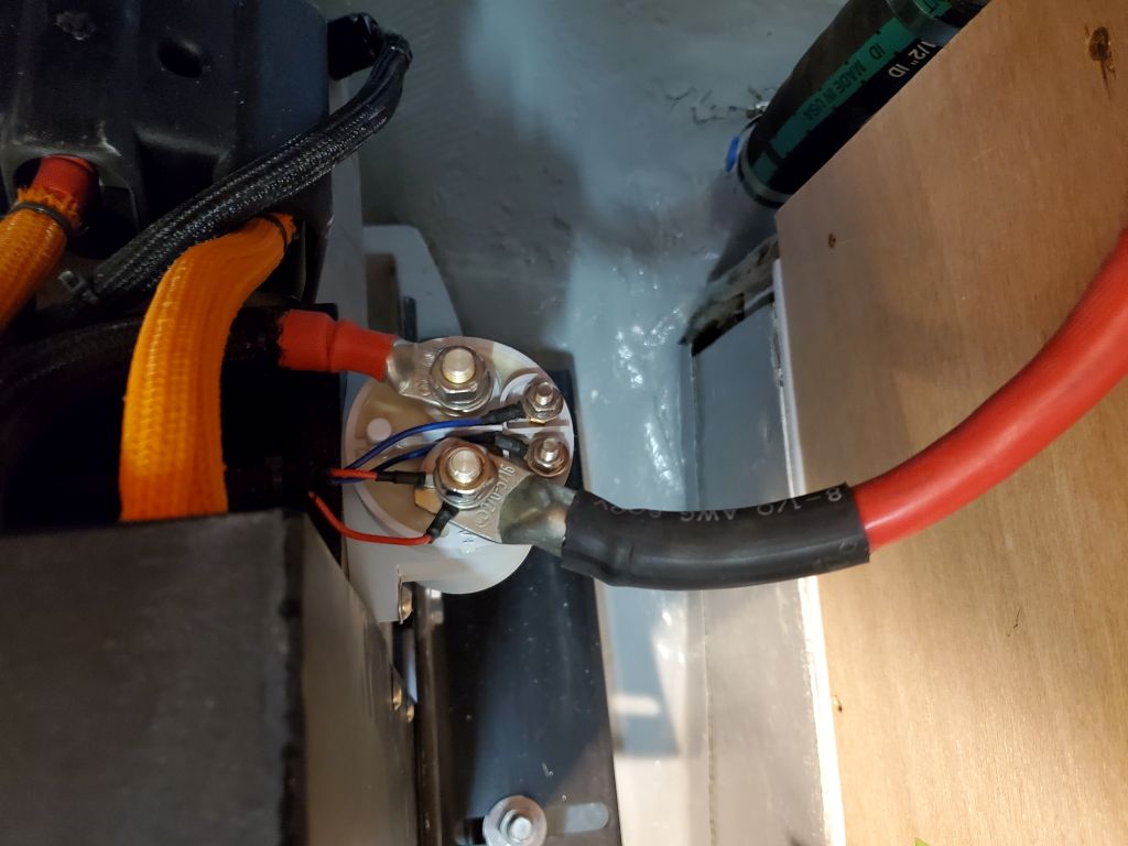
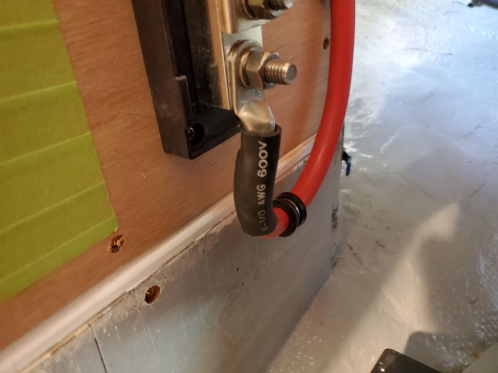
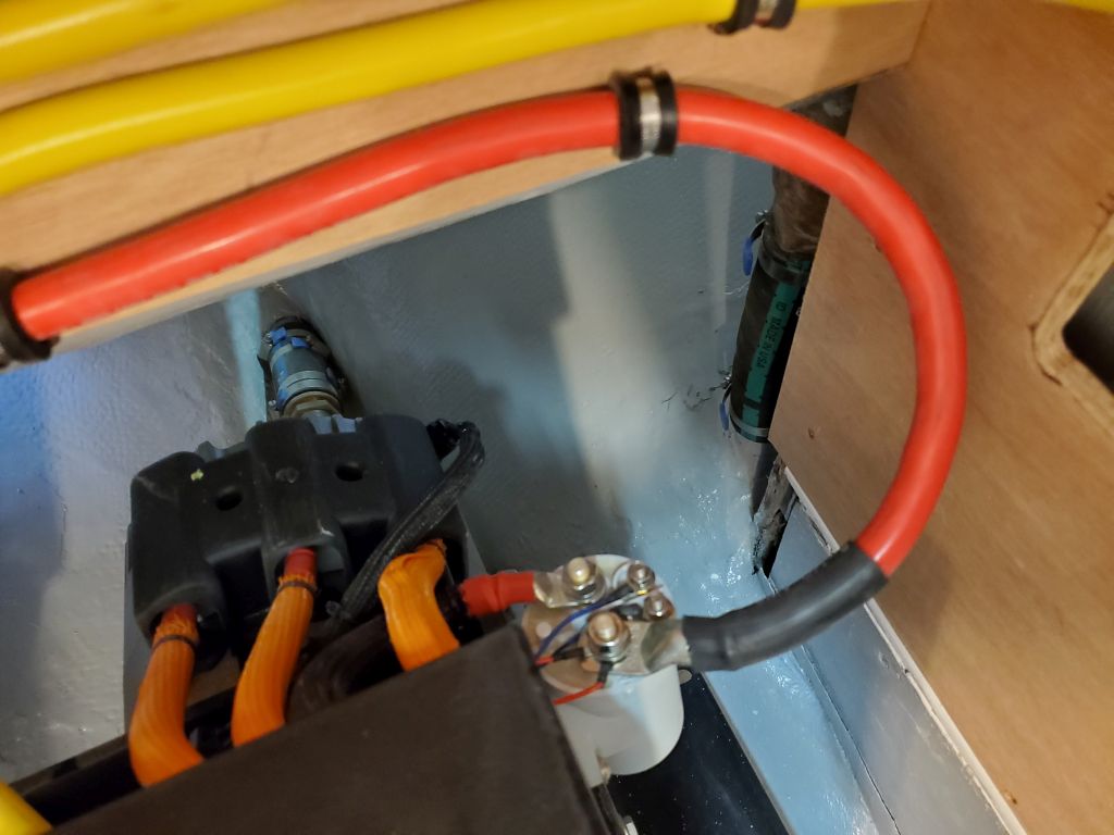
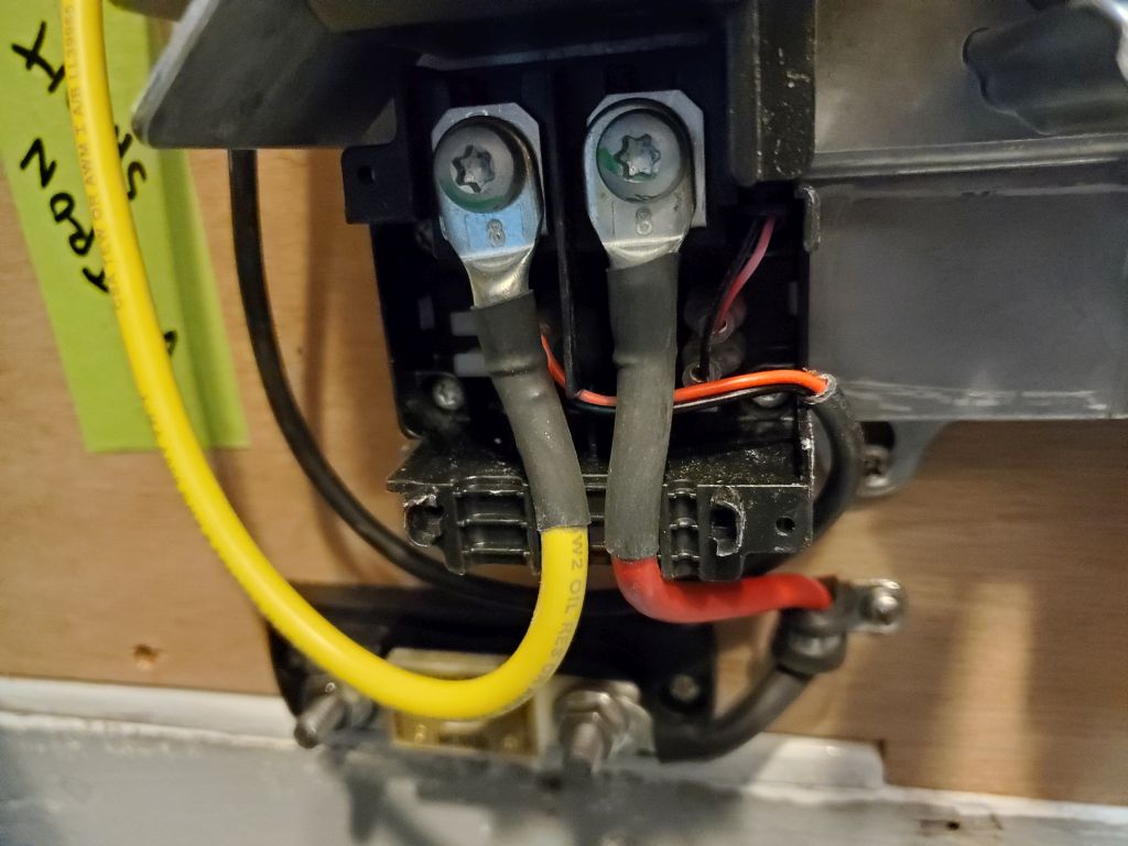
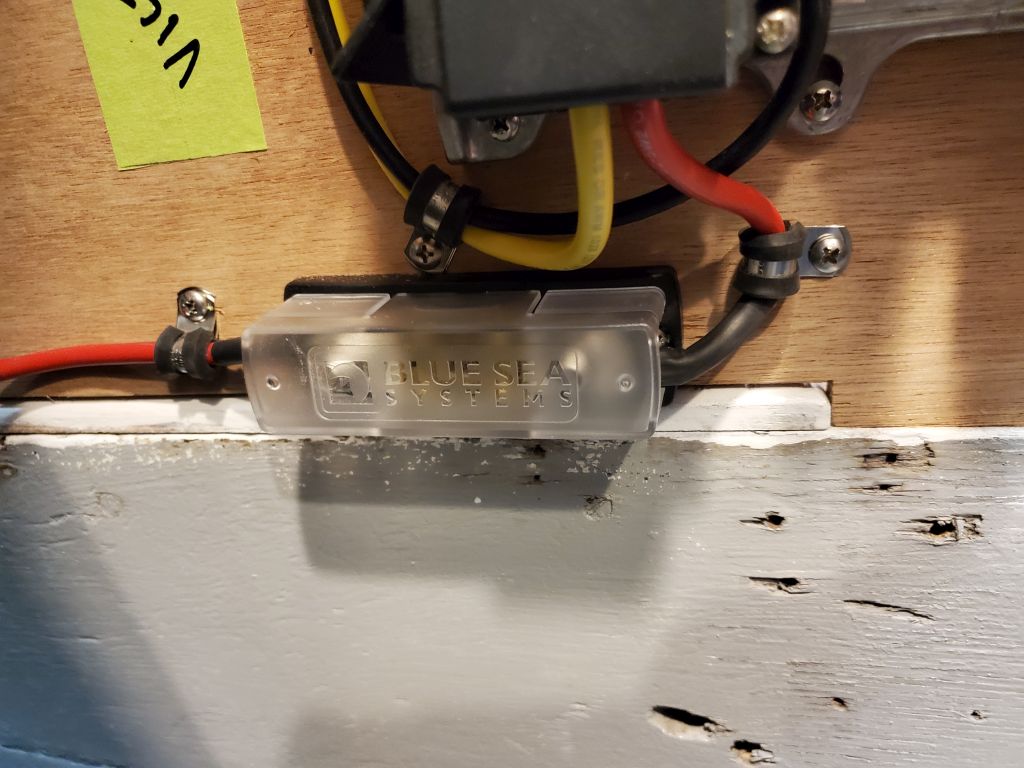
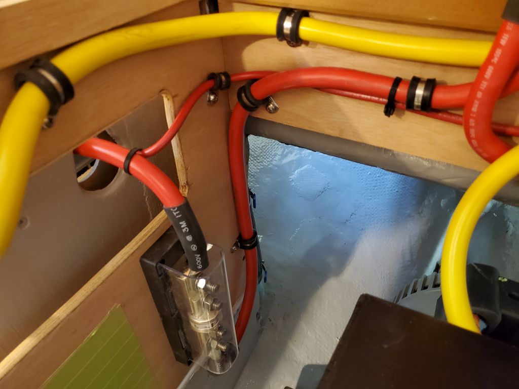
Two large cables remained: From the battery bank positive (via the fuse holder on the bulkhead) to the switch, and from the switch to the connection point on the electric motor. Unfortunately, the position of the studs on the switch itself were reversed from how I would have liked them to be for this configuration, but this couldn’t be helped–nor was it of any matter, other than requiring the cables to cross one another below the level of the countertop.


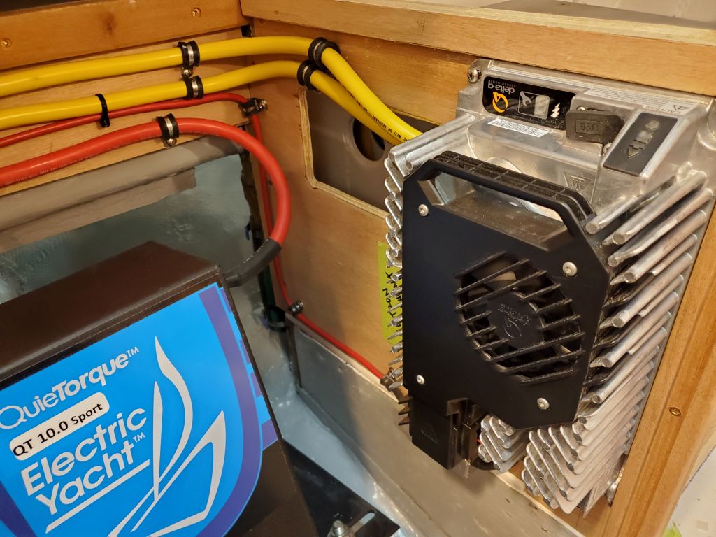
With the battery cables in place and secured as needed along their lengths, I turned to the engine bank battery charger. Documentation for this charger’s installation was hard to come by, with nothing included in the box per the usual convention these days, and in fact ultimately elusive to me during my initial internet search for same. Fortunately, I fooled them: I’d installed one before, and could refer to my previous installation and some hard-won (at the time) instructions for wiring the charger that I dug up from when I installed the other charger about a year before, and, knowing this, I cut short my time-wasting internet search in favor of my past notes.
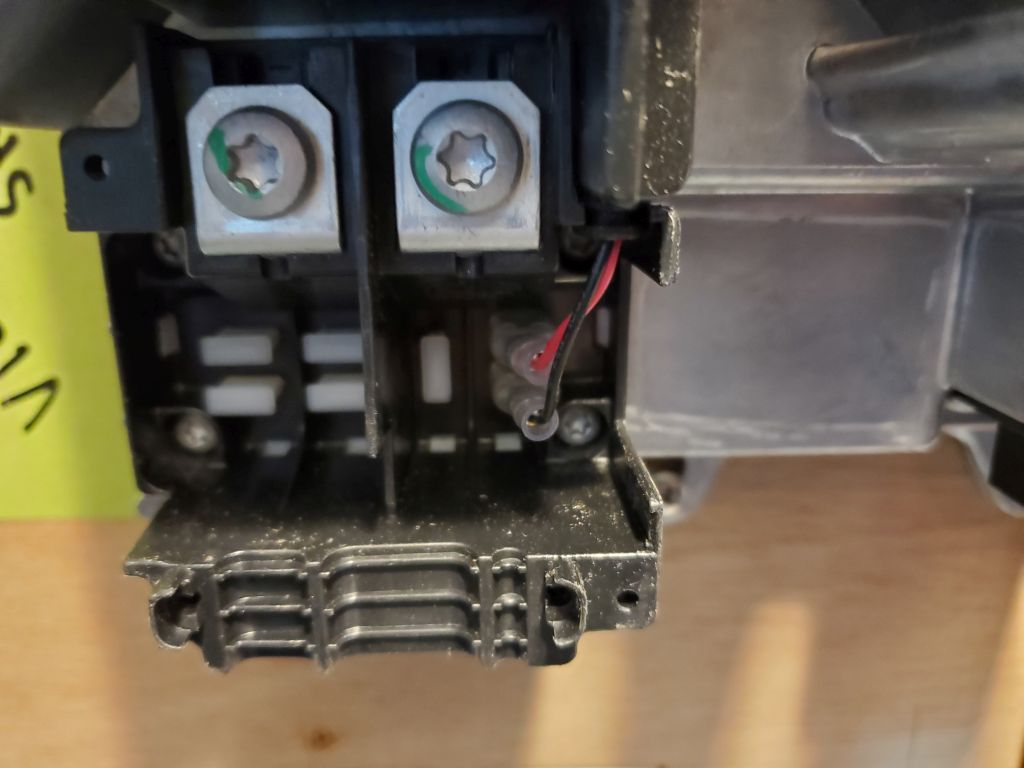
The charger required positive and negative leads to the battery bank, plus a battery temperature sensor connected to the bank negative terminal. The requisite terminals on the charger housing were poorly, if at all, marked, so my previous installation experience was invaluable.
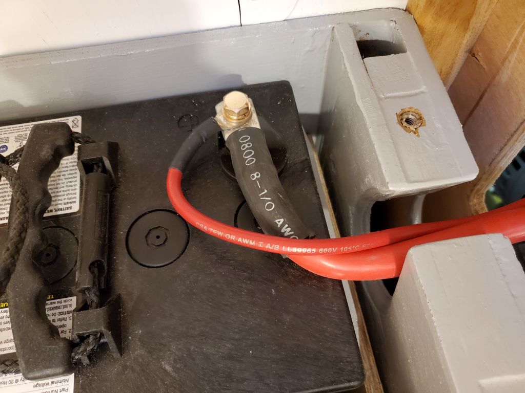
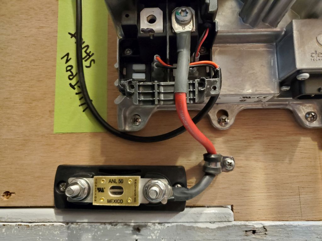
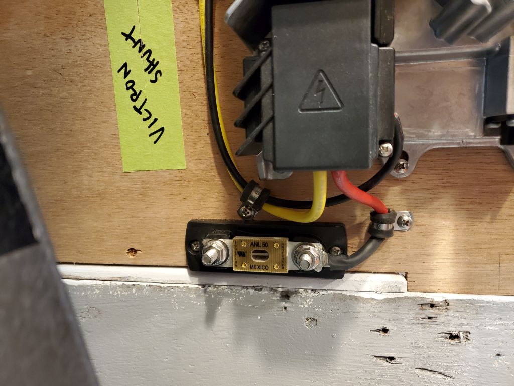
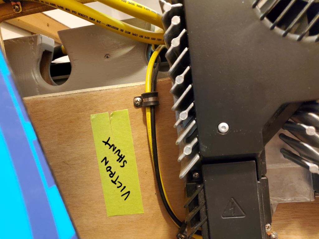
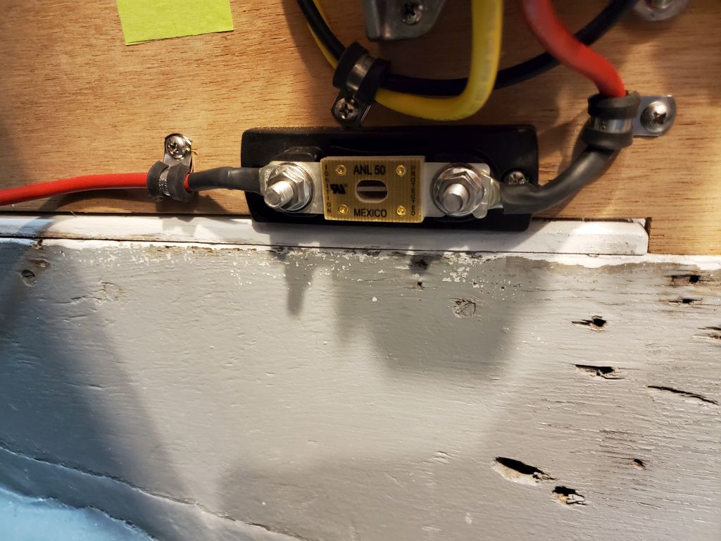
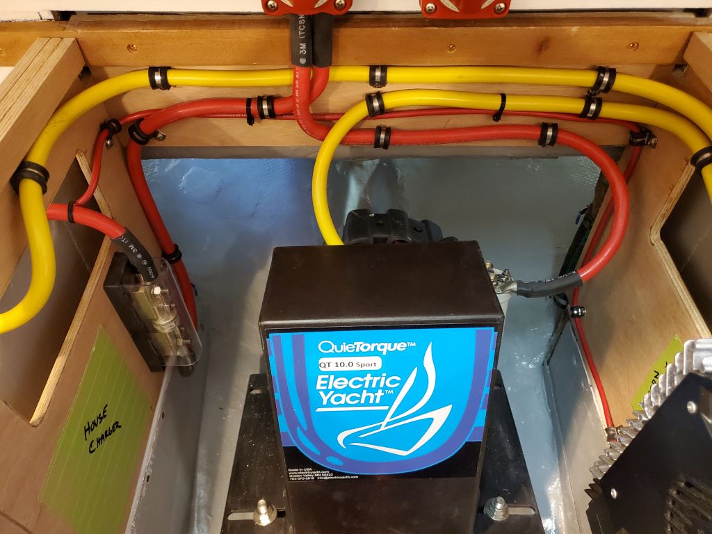
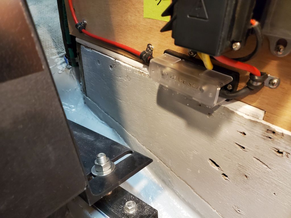
For the charger wiring, I chose 8AWG cable, somewhat larger than the charger documentation suggested, and ran the positive through a 50-amp fuse that I mounted just below the charger. This fuse was recommended in the general charger wiring documentation that came with the electric motor. From the fuse, I led the positive wire across the engine room and to the bank positive terminal on the starboard side.
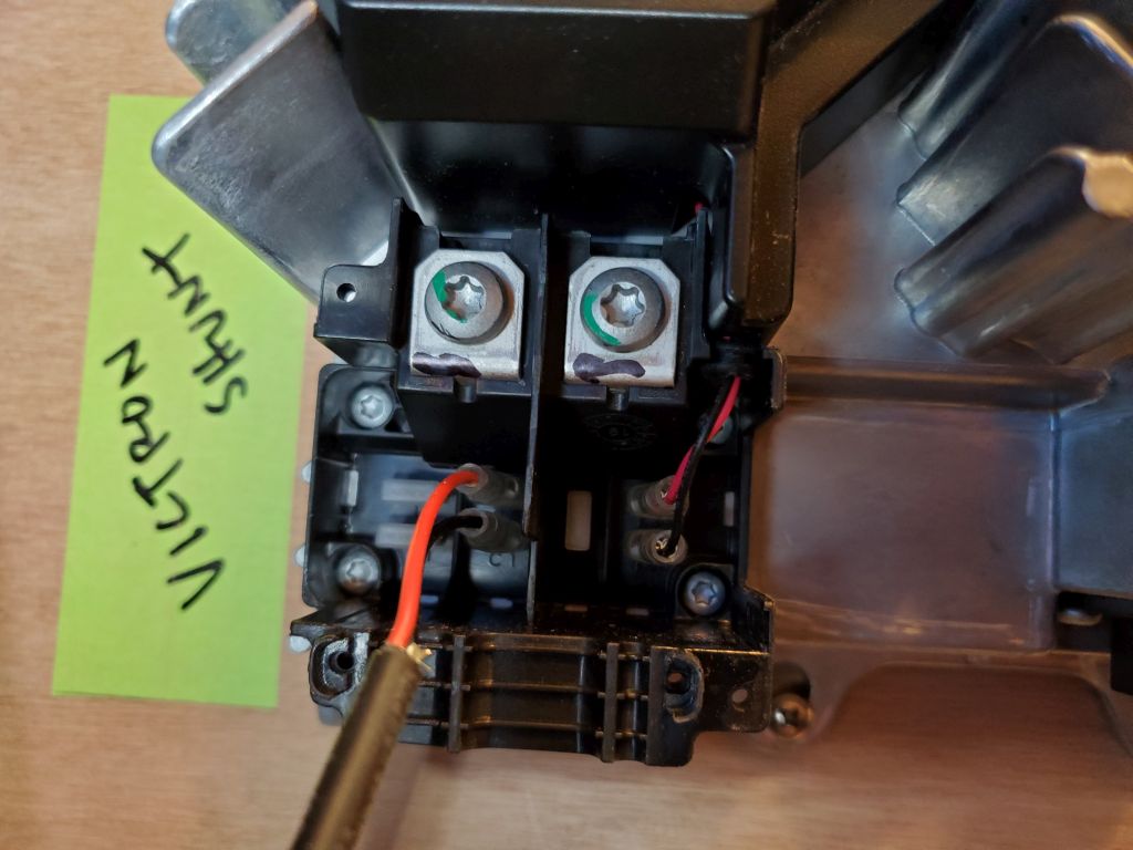
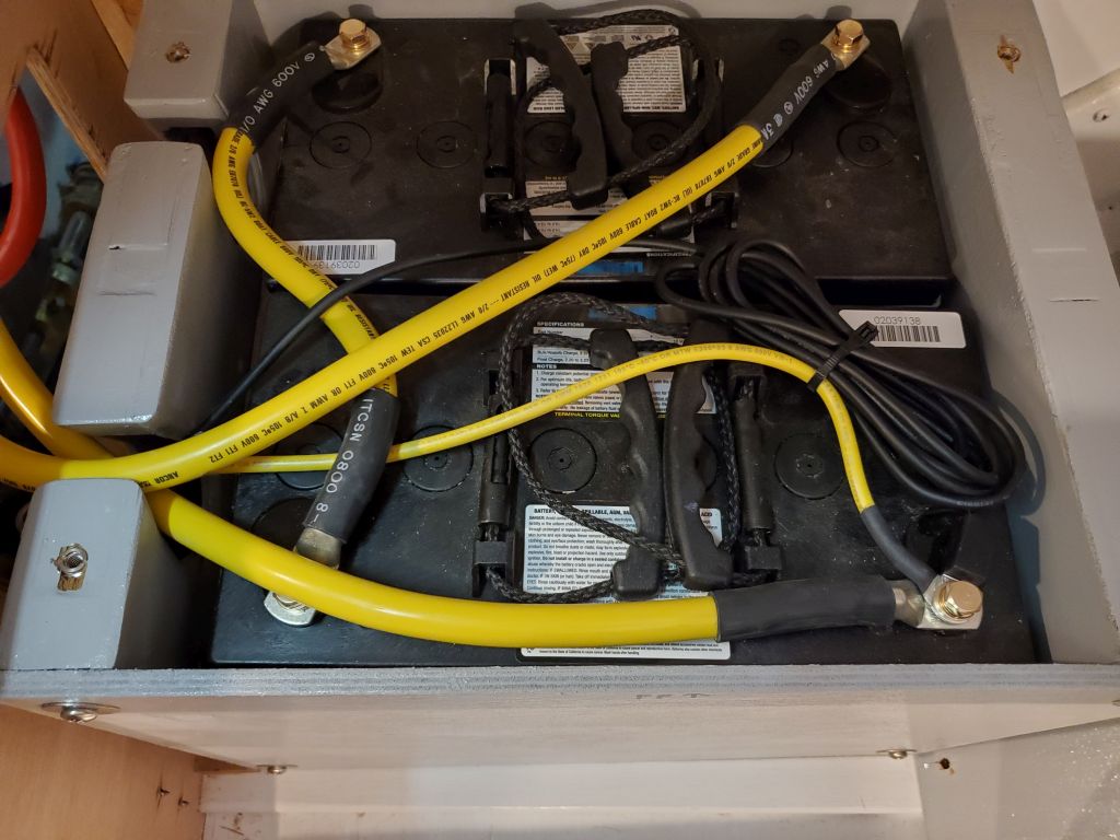
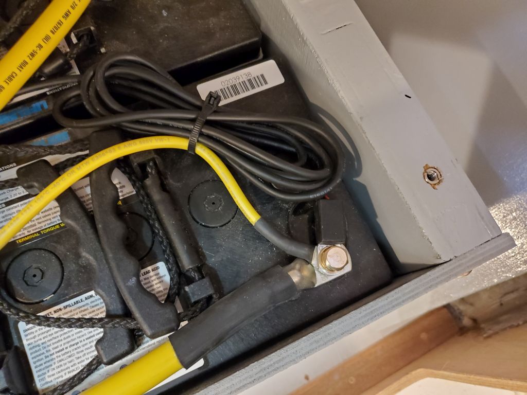
I led the negative cable, plus the wiring harness for the temperature sensor, up alongside the charger and into the port battery box, where I secured the wires to the negative terminal. To make room, I moved the “shunt” over a bit, as there was still lavish space available for it elsewhere.
All that remained to complete the electric motor installation now was to install the supplied control lever and battery monitor panel in the cockpit, which I would do once the cockpit was painted. Next time, I’d double-check all my connections, then test-fire the charger.

Total time billed on this job today: 3.25 hours
0600 Weather Observation: 35°, cloudy. Forecast for the day: Chance of showers, 49°