


March 17, 2021
Lyra 40
Wednesday
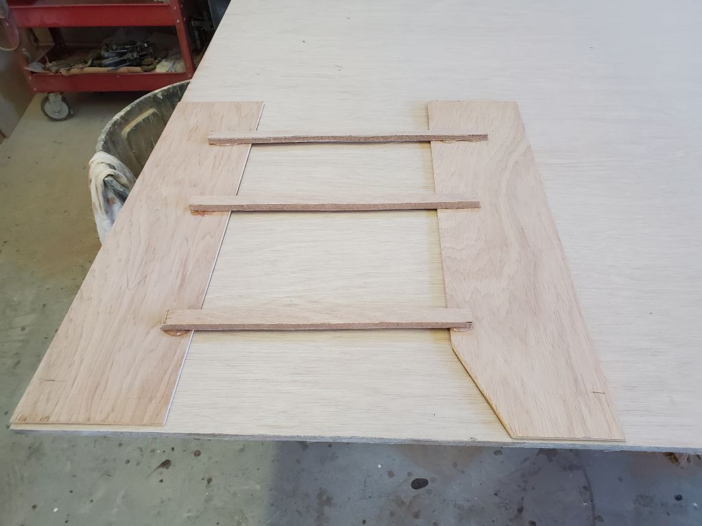
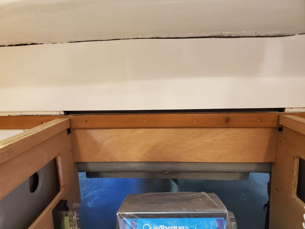
The last piece of countertop for the galley proper was the small section above the engine room. From scrap plywood, I made a simple yet accurate template, then cut the section slightly overlong from 12mm plywood, marking and trimming the forward edge to match the forward edge of the engine room side trim.
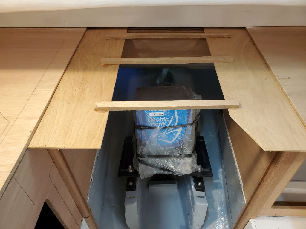
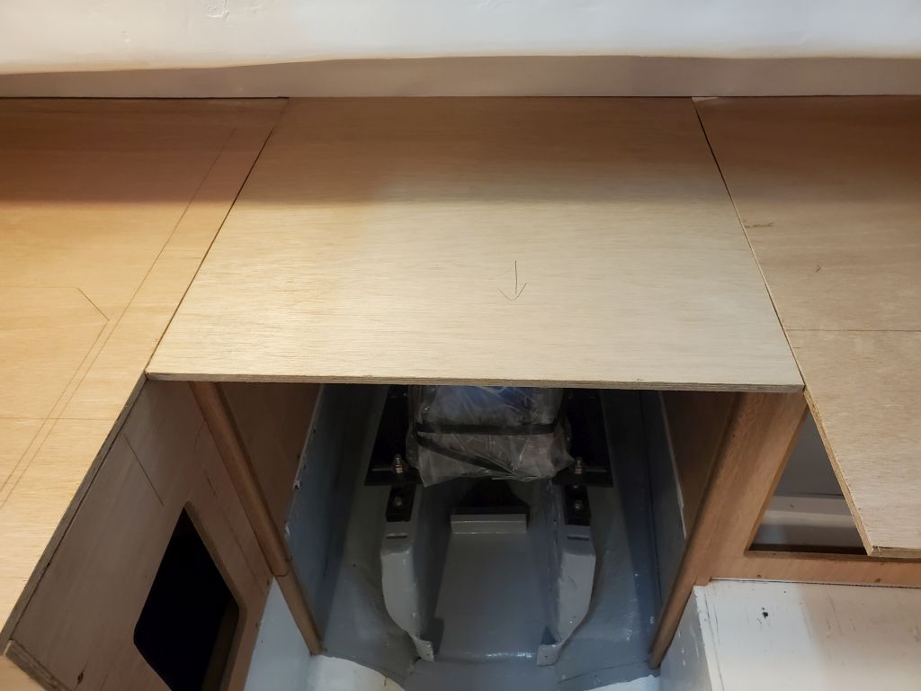
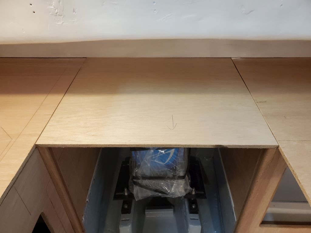


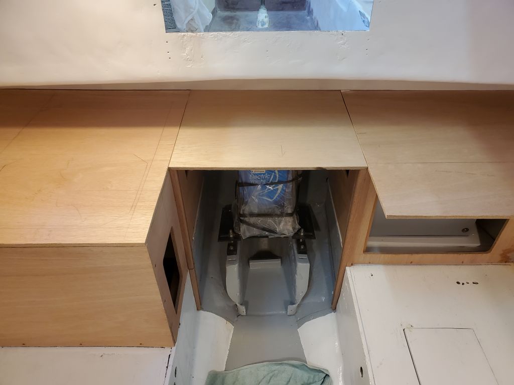
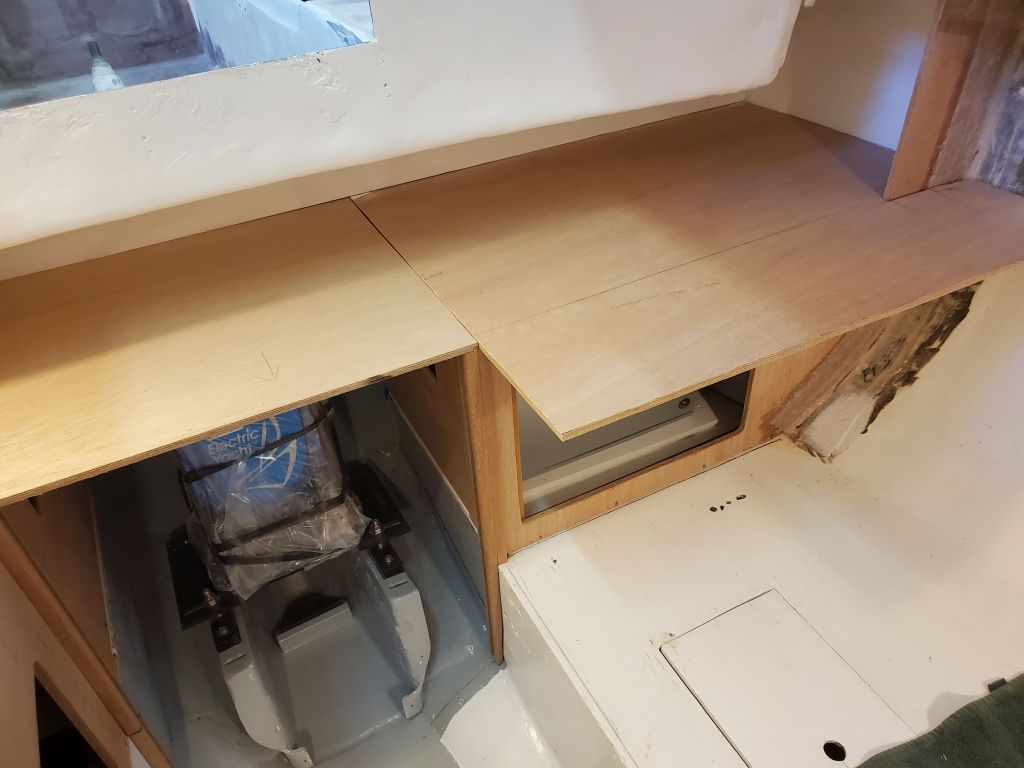
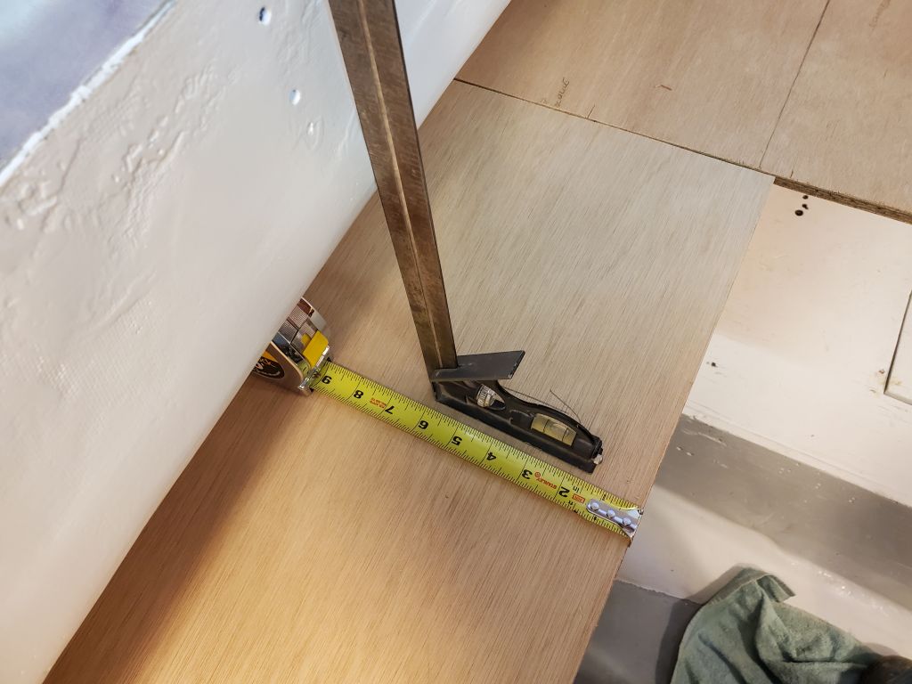
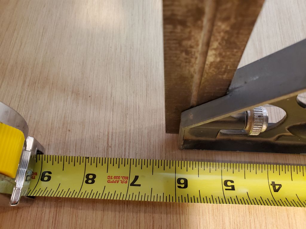
This design left over 6″ of clear countertop beneath the companionway and forward of the bridgedeck, good enough for galley work and potentially available as a first step depending on the final companionway ladder details.
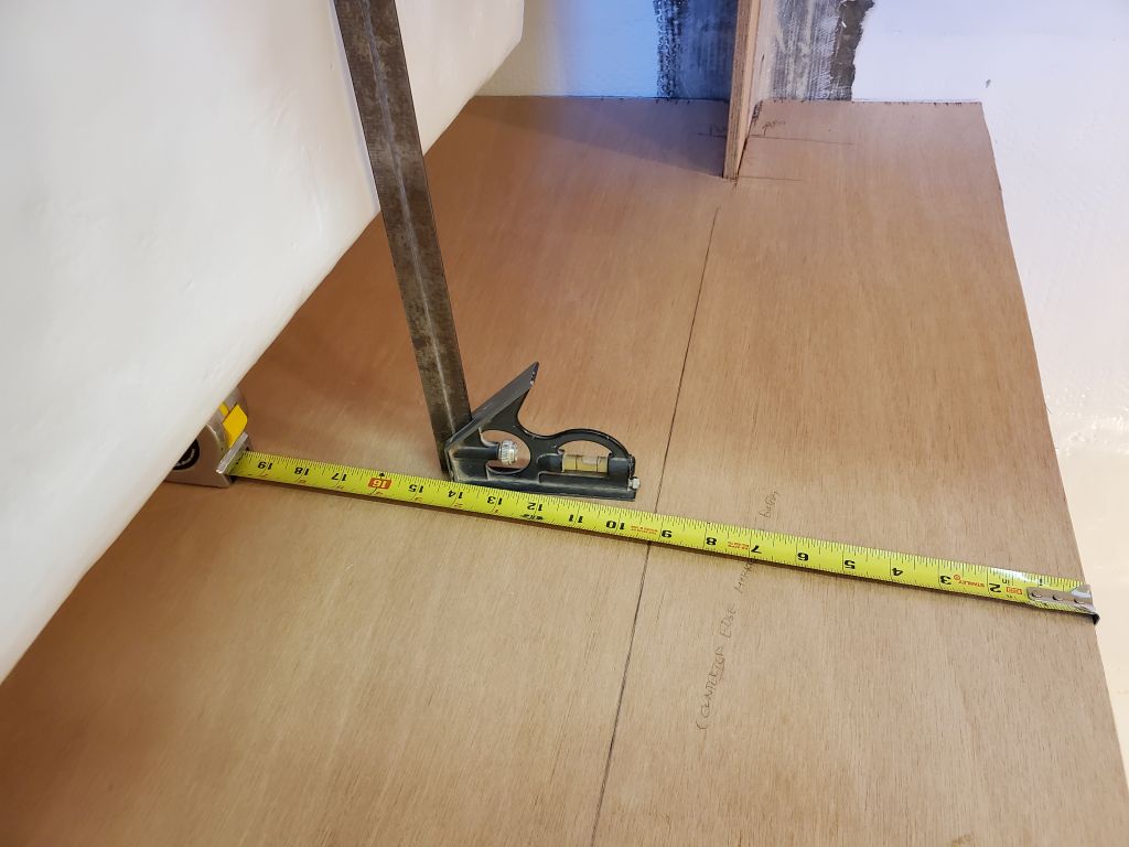
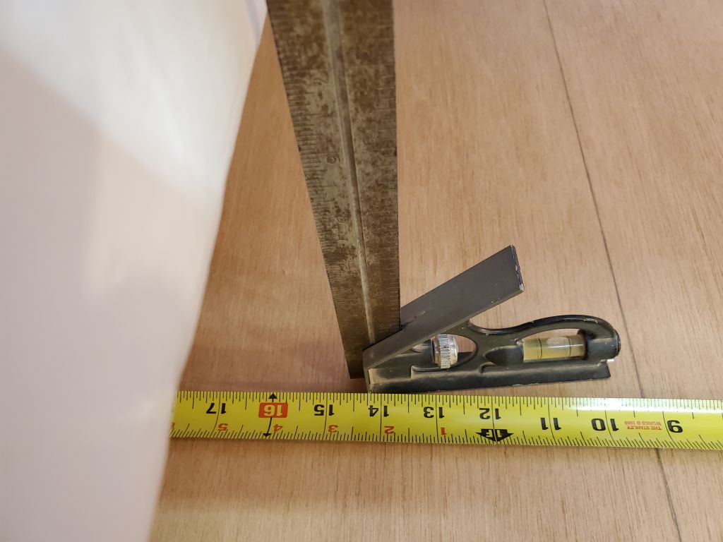
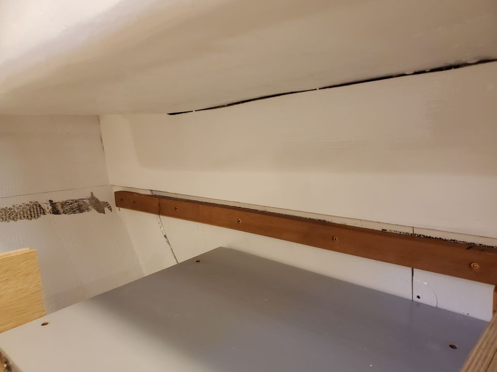
On the port side, with the wide overhang, there was over 14″ of clear counterspace before the bridgedeck.
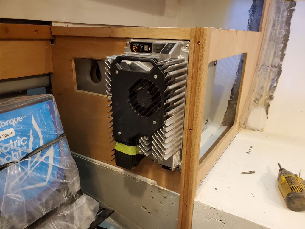
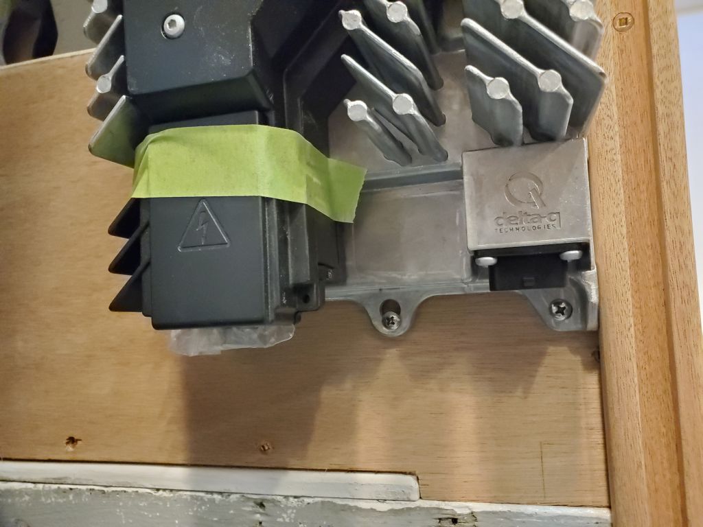
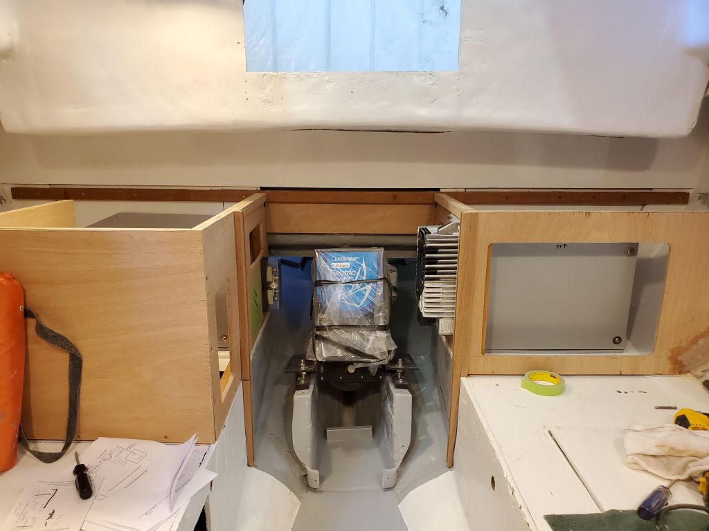
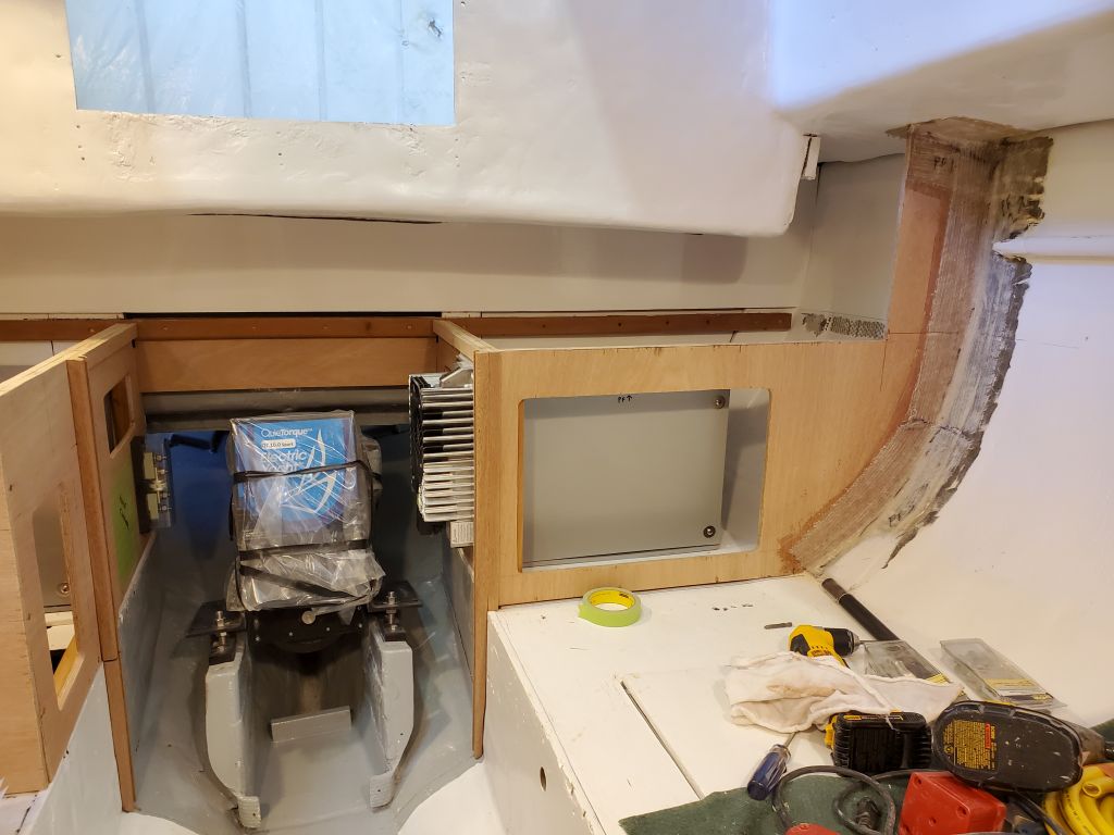
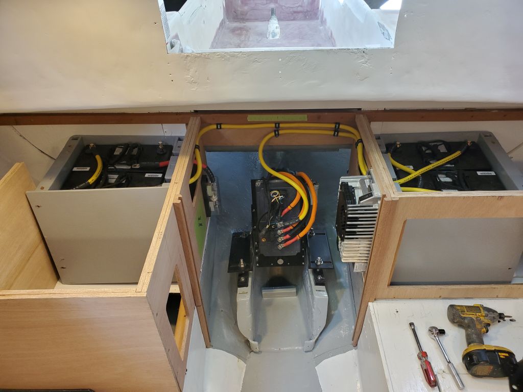
With all the basics of the galley and engine room in place now, I could shift focus for the moment to the critical installations and wiring related to the electric motor. In the engine room, I started by installing the large 48-volt charger at the forward edge of the port bulkhead. This charger design is a little like a pushmi-pullyu, as both ends, yet neither end, was really heads up: Whichever way it was oriented, something was upside down. I considered both ways of mounting it before finally deciding that the power cable and battery cable connections would be better off at the bottom, and the “controls”, as it were, at the top–even though they’d be upside down. This orientation allowed me to keep the top of the charger just beneath the countertop support cleats, with ample room beneath for the cables and even a 110-volt outlet should one be added later.

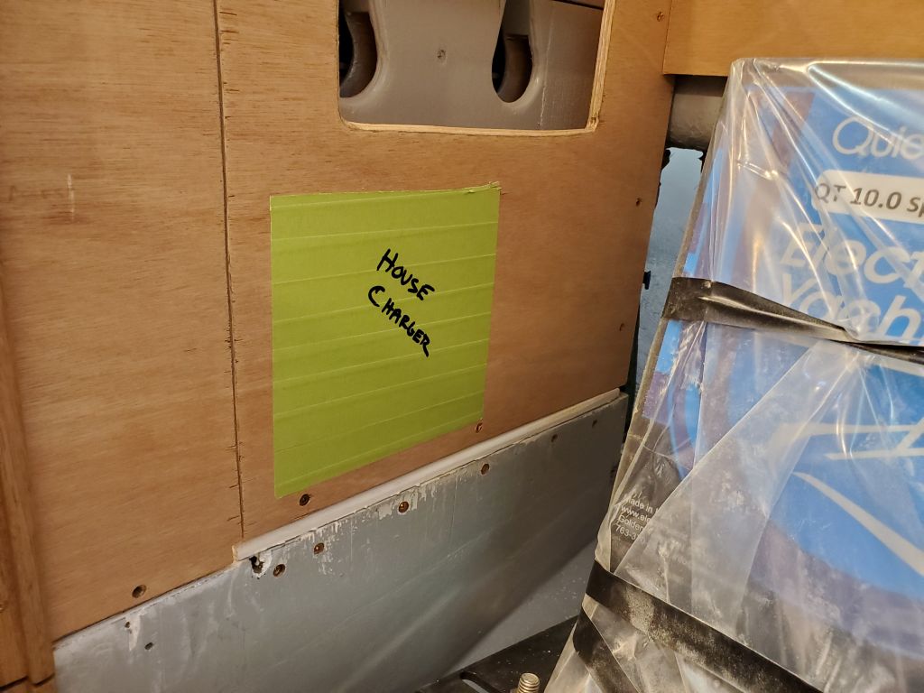
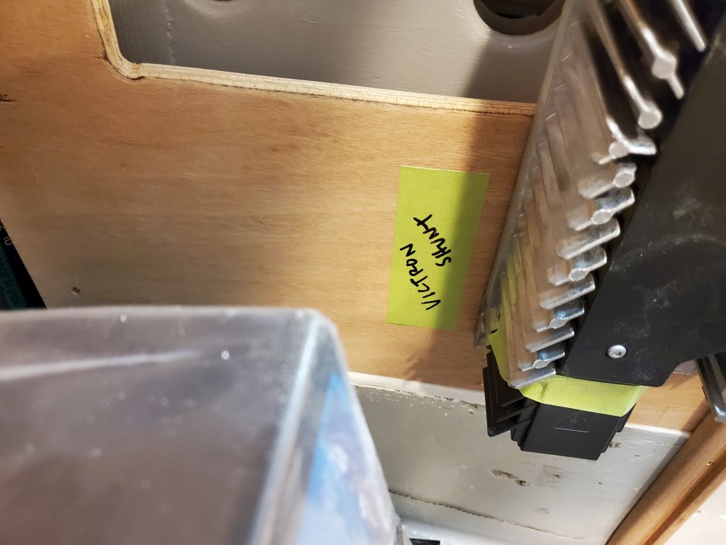
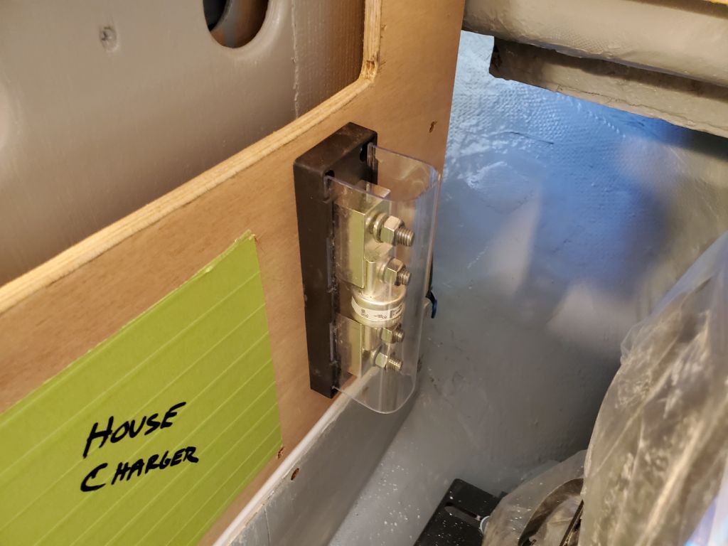
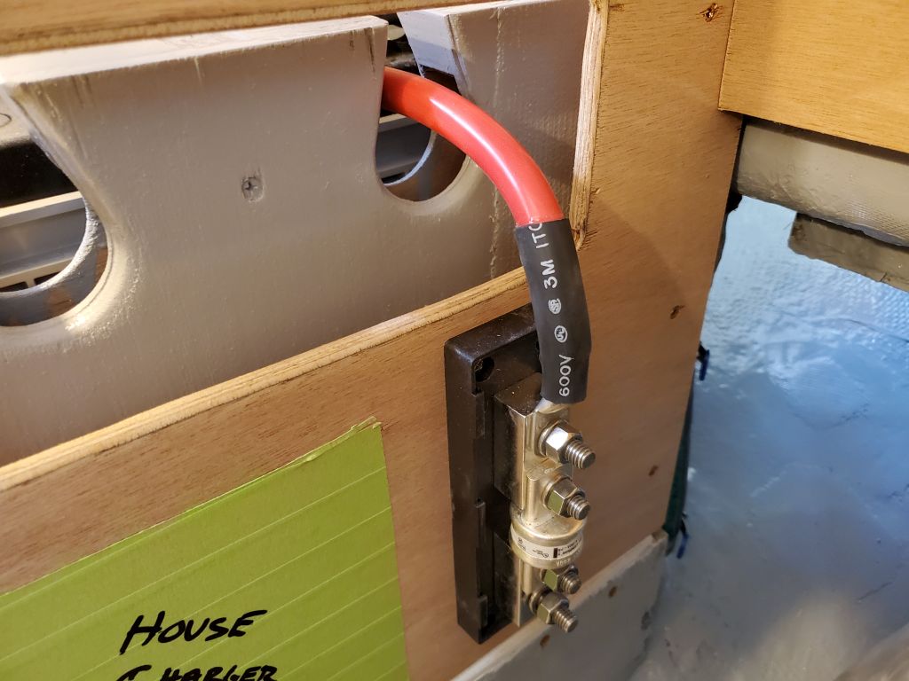
I didn’t have the 12-volt charger for the house bank on hand, but had a mockup of its overall size, and to reserve space in the engine room I marked out the future mounting position with tape. Similarly, I marked out a mounting position for the shunt required for the battery monitor the owner had for the house bank, leaving ample room for this installation and its wiring next to the engine bank charger on the port side.
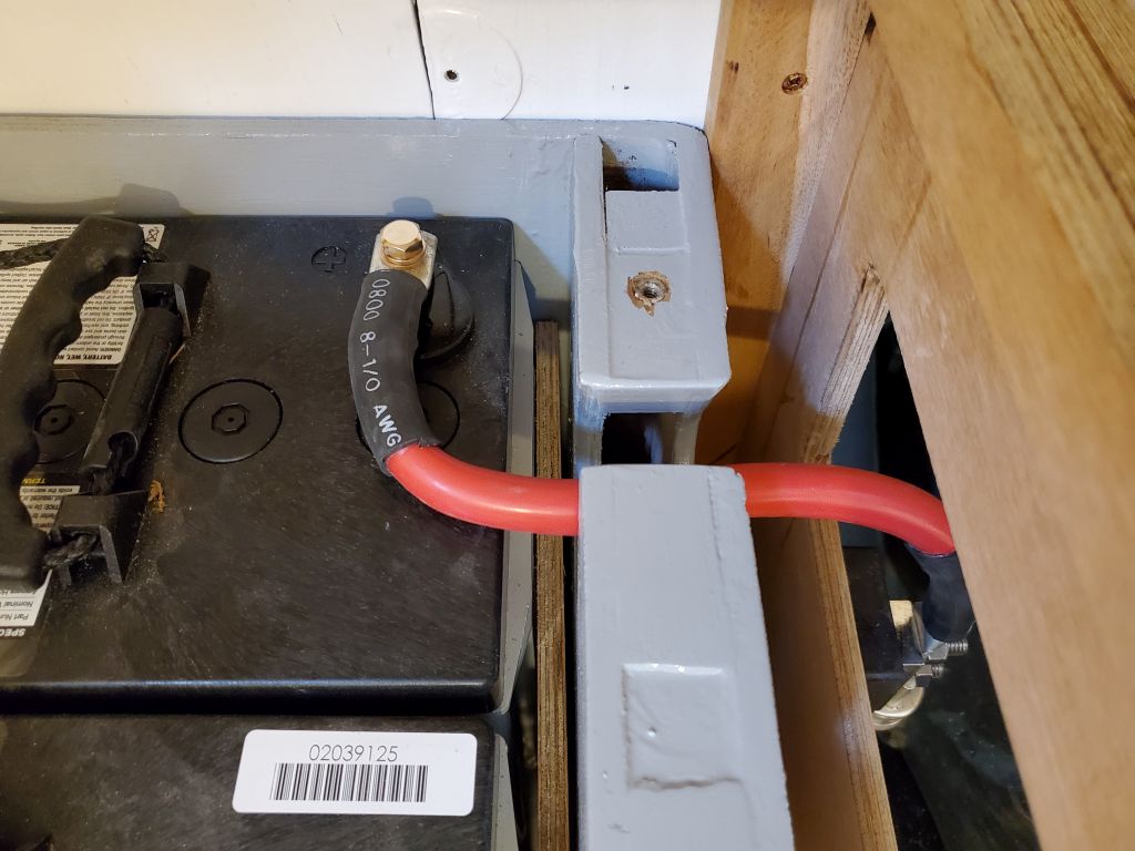
The final bit of hardware to pre-install was the large fuse housing for the propulsion bank, which, after considering the whole battery wiring setup in general, I eventually located on the aft end of the starboard bulkhead, inline with one of the battery box wiring ports.
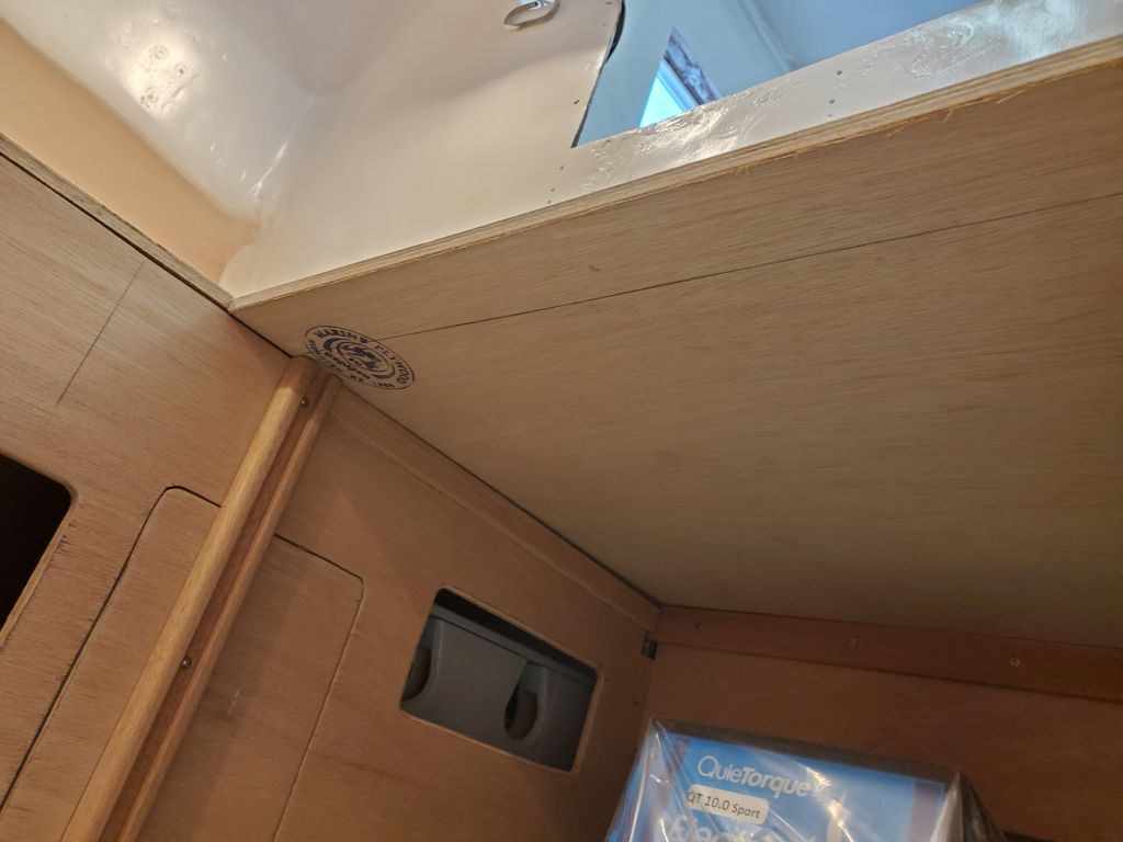
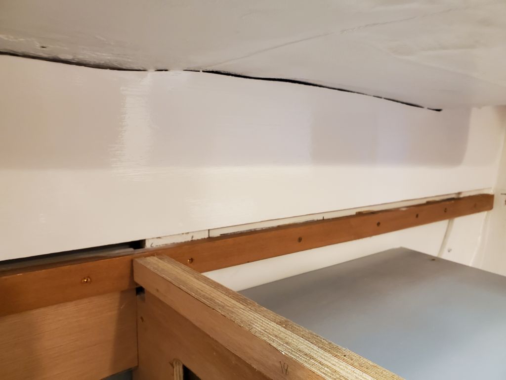
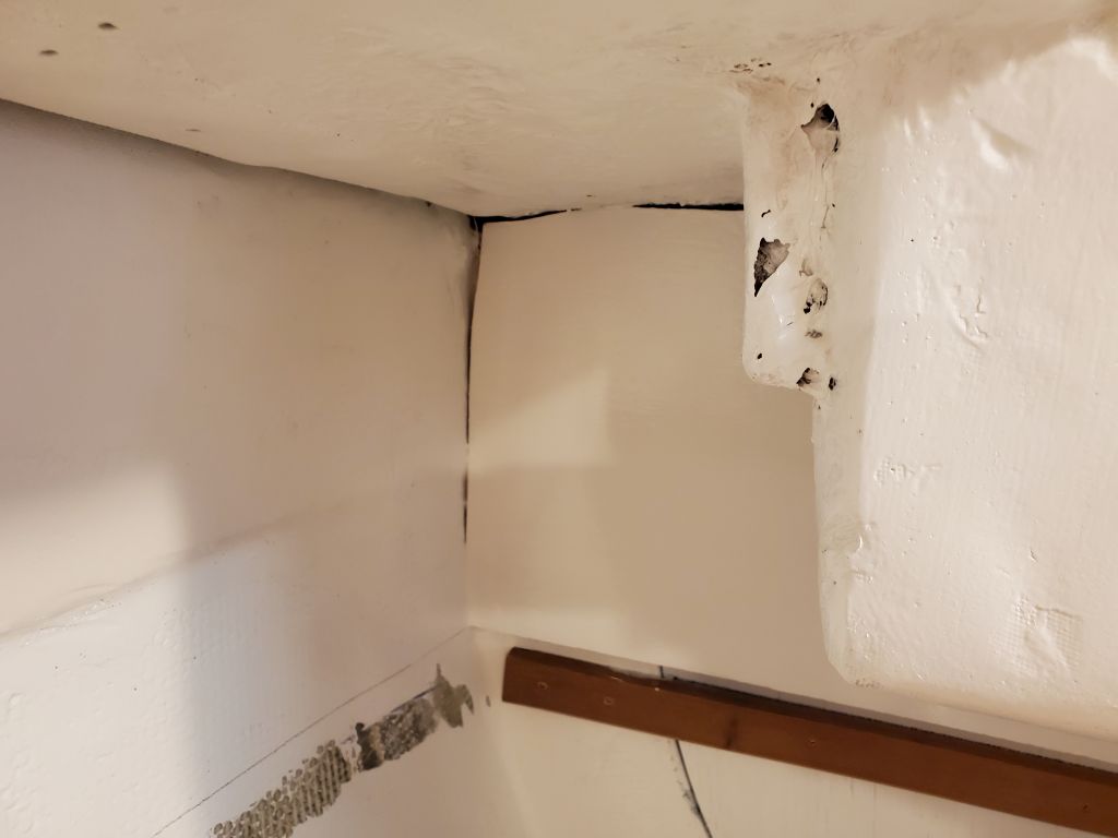
Before continuing, after a light sanding I applied a coat of the semi-gloss white enamel paint to the aft bulkhead above the galley, as I needed this bulkhead complete before I could install the battery switches. This had a little time to set up before I got back to work in the engine room, but in any event I didn’t need to touch it as I continued working.

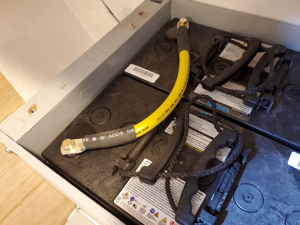
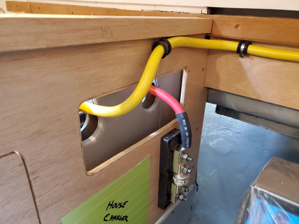
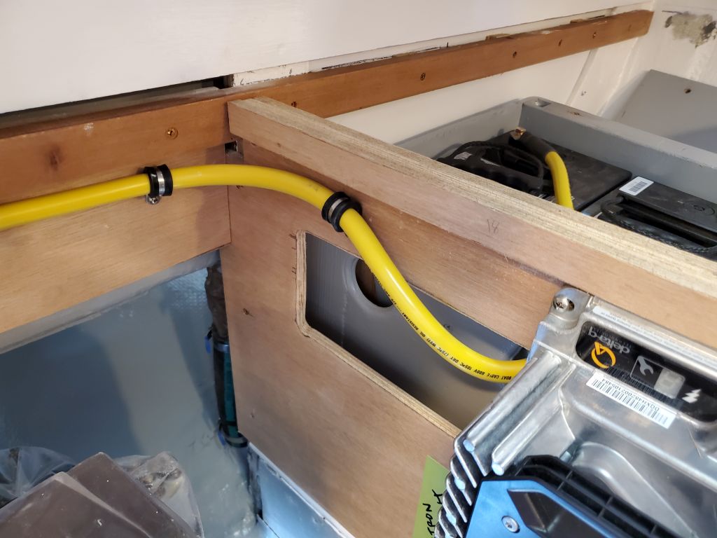
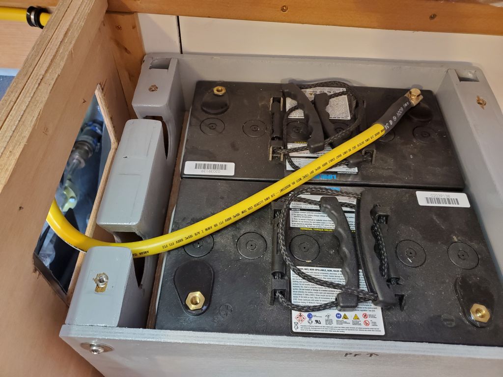
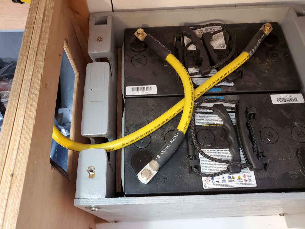
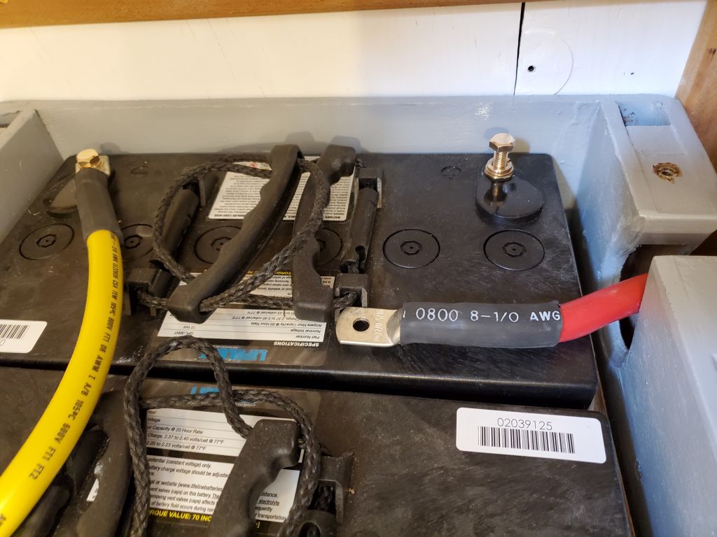
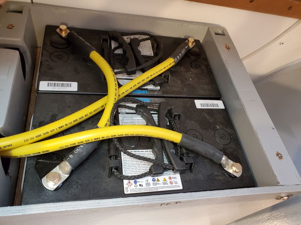
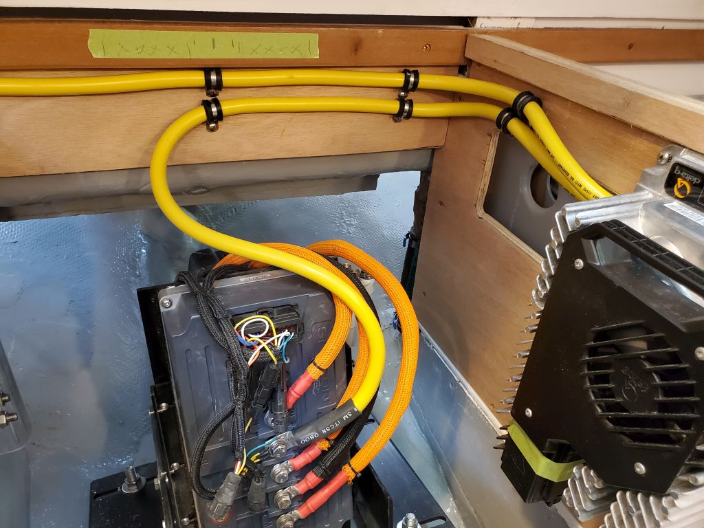
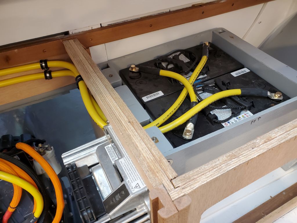
Starting with the positive cable from the battery bank to the fuse holder, I spent the remainder of the afternoon installing all the cables required to tie the batteries together in series, creating the 48-volt bank required for the propulsion motor, the first step in the final motor wiring. With the positive terminal of the 4-battery bank thusly determined, I moved through the remaining batteries connecting negative to positive with jumpers–which in this case included a long jumper that extended across the aft end of the engine room to the port battery bank. I used yellow cable for these jumpers since logic suggested it was debatable what color they should be anyway, and I always used more red cable than yellow, so as a matter of supply it seemed to make sense. I planned the cable runs so as to maximize space for additional wiring in the space, and to provide room and passage for the additional cables that would come later, once I was ready to mount the battery switches.


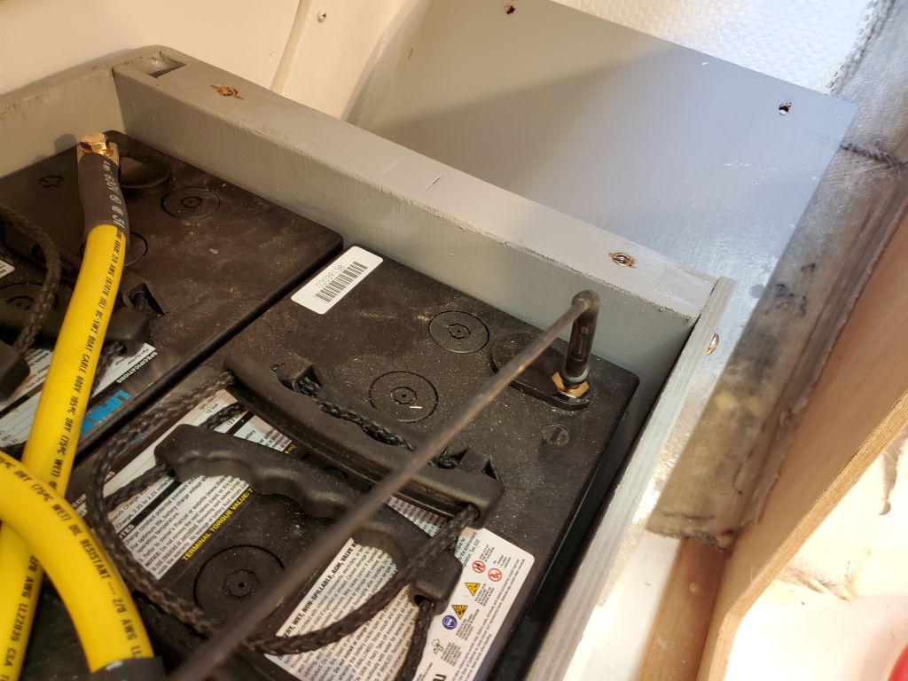
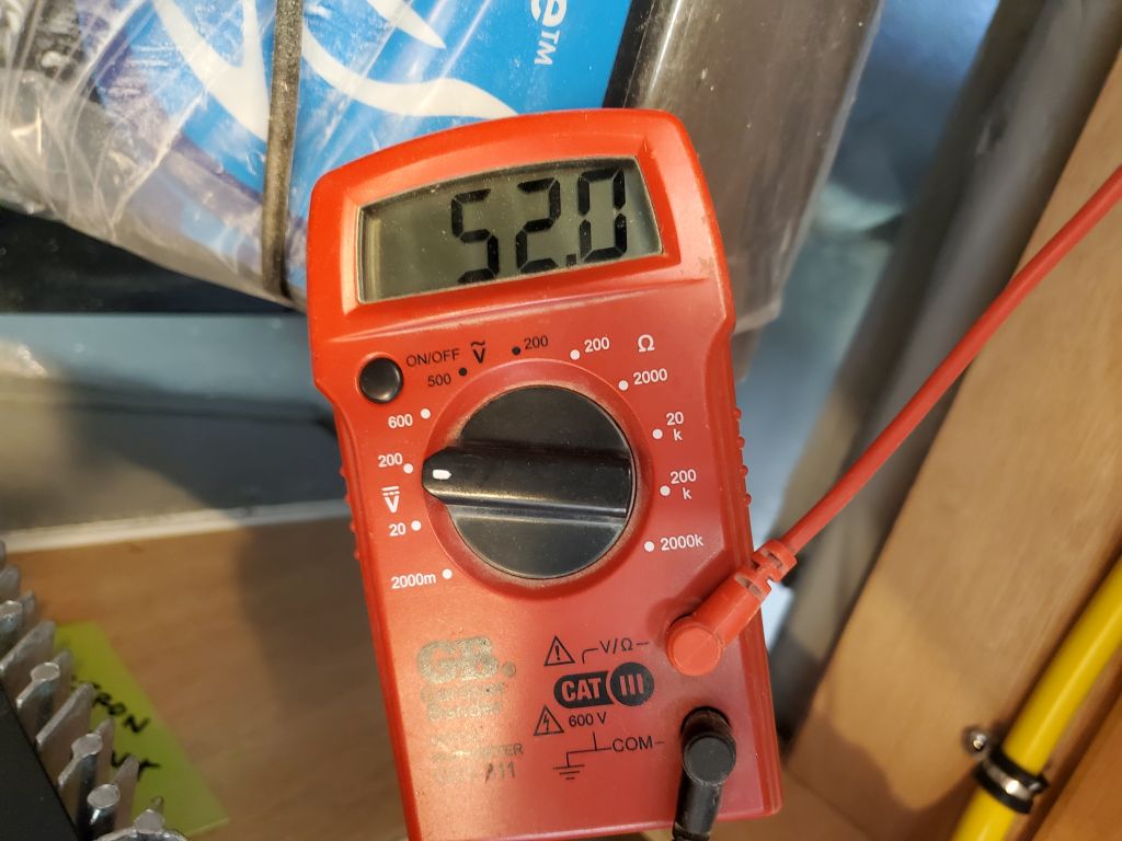
With all four batteries connected in series, I tested the voltage between the bank positive terminal to starboard and the bank negative terminal to port: 52 volts, which was what I’d expected from a fully-charged new bank of nominal 48-volts. This was quite a stretch for the standard leads from my meter, but they just reached.
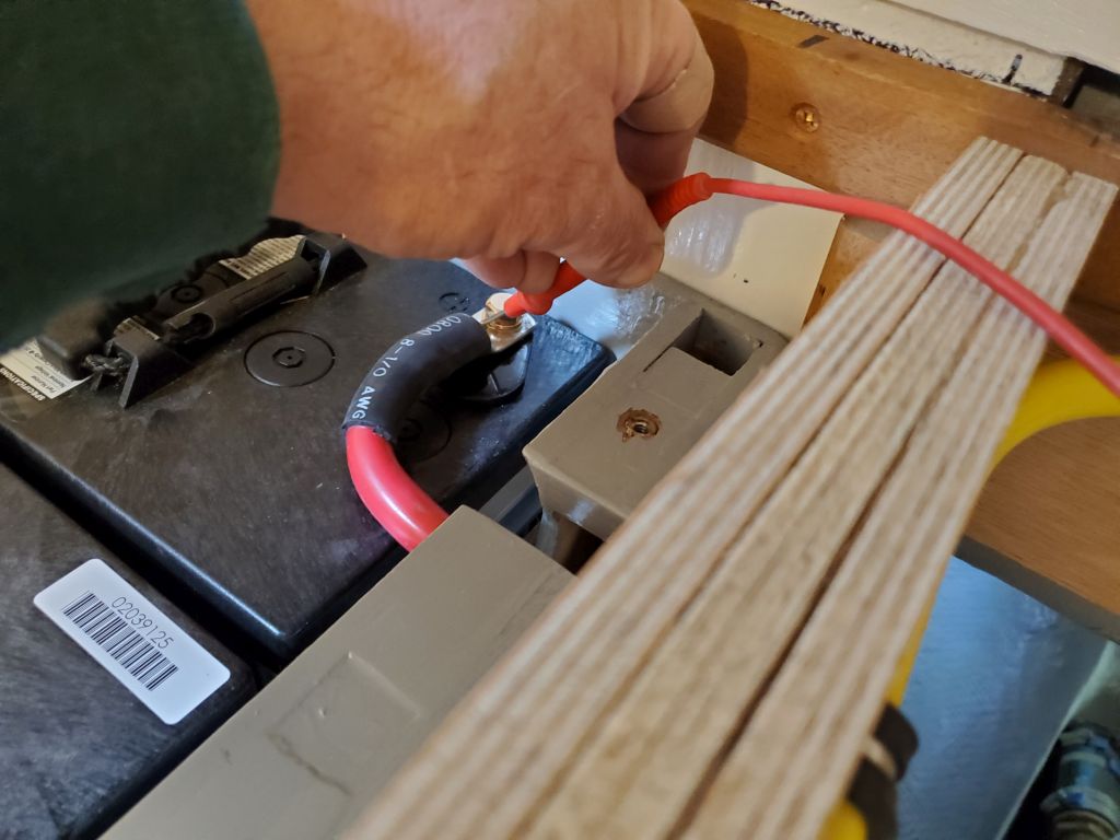
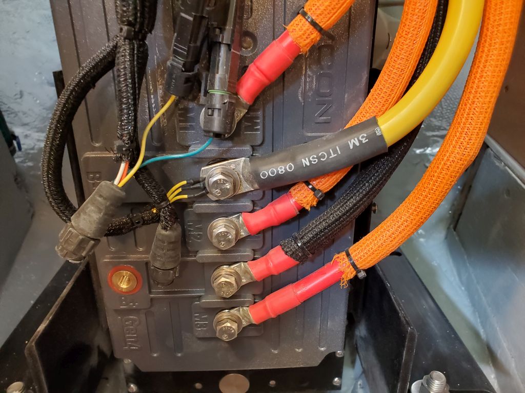
For now, I disconnected the positive wire till I had the rest of the system installed, and to finish up for the day I installed the negative cable from the bank negative on the port side to the appropriate terminal on the front of the electric motor controller, leading the cable around the back of the engine room and down the front of the motor along with the various pre-installed cables already there.
Next time, I planned to finish up the cabling with the remainder of the positive side of the system.
Total time billed on this job today: 5.5 hours
0600 Weather Observation: 16°, clear. Forecast for the day: Sunny, 50°