March 1, 2021
Lyra 28
Monday
In the lazarette, I gave the newest work a light sanding as needed (the chocks for the generator and the new engine exhaust fill), then installed a fiberglass patch over the inside of the engine exhaust to complete the work there.
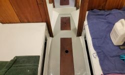
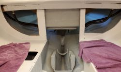
Some of the low-tack masking tape lining the cabin sole had lived up to its name and come partially unstuck and, in some cases, completely loose after the painting, and this left a less-crisp line of demarcation than I’d hoped for, but the new sole still looked OK. I’d probably do another coat later in the project, but for now I could install the bilge hatches and cover the sole with some cloths for protection while I turned to other pursuits.
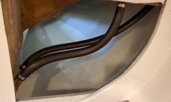
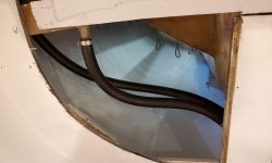
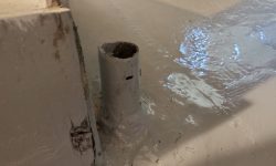
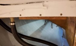
The first order of reassembly business now that the cabin painting was essentially done (pending touch-ups and new work to come) was the cockpit scuppers, including the seat and sidedeck drains. These areas would soon be inaccessible or, at best, challenging to access, so now was the time to install new hoses and clamps all around.
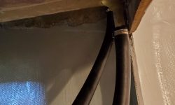
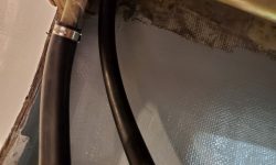
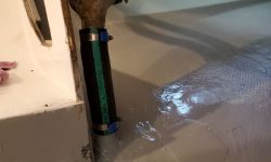
The sidedeck and cockpit seat drains led from their openings to a sort of Christmas tree arrangement of fiberglass tube barbs glassed to the main cockpit scuppers. I’d measured these at 1″ diameter, and bought hose accordingly. So I was rather surprised when on the very first hose, I had great difficulty getting the hose to fit over the fiberglass tube beneath the cockpit. I fought with it for a while but couldn’t stretch the hose over the tube and get it down far enough, so I ended up sanding the exterior of the tube a bit, after which I could finally get the hose on and clamped successfully. Fortunately, this particular tube seemed to be an anomaly, as the other end of this hose–and in fact all the remaining hoses–slid on their respective tubes without any undue issues.
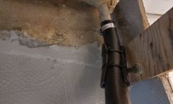
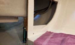
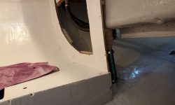
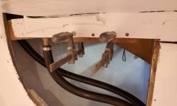
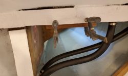
On the port sidedeck drain hose, I added some chafe gear where the hose led close by some bolts sticking out the back of the nearby bulkhead.
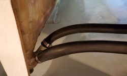
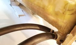
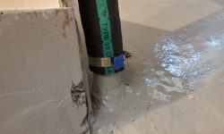
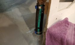
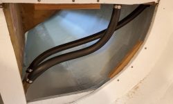
Next, I turned to the 1-1/2″ hoses for the main cockpit scuppers. These short hoses led directly from the fiberglassed scupper tubes to similar tubes glassed into the hull nearly directly beneath, leaving little room for hose manipulation. Knowing this issue in advance, I’d purchased hose specifically for the task that was a bit more flexible than the typical hardwall, wire-reinforced hose I might have otherwise used, hoping it would fit better in the tight space. The fabric-reinforced coolant hose would be plenty strong, but much more supple for installation.
Before beginning, I made a mark on the hull tube end to give me a reference for how far onto those tubes, at a minimum, the hose needed to extend for good clamping. If I couldn’t see the mark when all was said and done, I’d know all was well. As it happened, the hose worked well for the application, as hoped, and I had little trouble installing it by forcing it down onto the hull barb as far as possible, then bending and manipulating the top end onto the tube beneath the cockpit, after which I could pull the hose back up while still leaving plenty of hose on the lower barb for clamping.
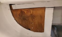
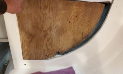
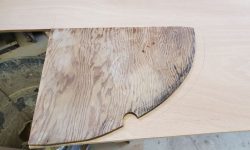
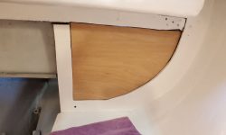
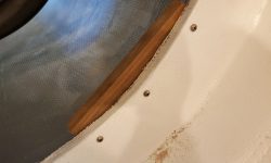
The starboard aft bulkhead originally (and still) had a little plywood insert to fill in the space, but because the port side had been behind the old icebox, there was no such piece there. Now, to fill in that side, I used the starboard piece as a rough template to mark and cut out an insert from 12mm plywood to fit the port side. These inserts would never be seen once the interior was finished, but would close off the lockers from the cabinets and interior spaces, and vise-versa. They’d remain theoretically removable should it be necessary sometime far down the road.
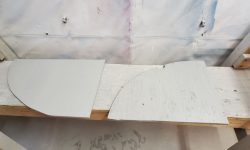
To prepare for installation, I painted the back (locker) sides of the two sections with the gray bilge paint. The old piece (on the right in the photo) soaked in all the paint in short order, leaving an almost bare-looking surface, and I’d meant to recoat them at the end of the day, but forgot, so I’d do that next time.
There were a couple wooden cleats behind the bulkhead web that would help support the inserts, and give places to install fasteners, but the port side needed a couple more, and I thought another one at the top of the starboard side would be helpful, so from leftover teak cutoffs I made up a few new cleats and secured them with screws, ready to accept the plywood soon.
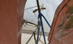
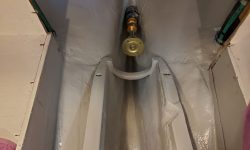
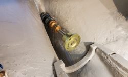
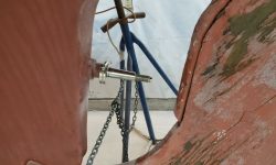
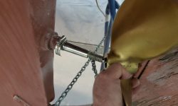
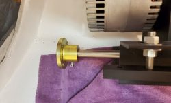
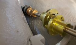
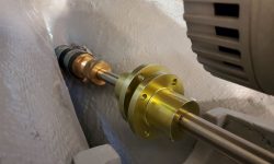
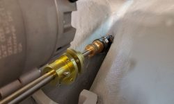
Now I was ready to start the basics of the electric motor installation. To begin, I temporarily installed the shaft coupling on the prop shaft (leftover shaft–but much newer than original and in excellent condition–from the Atomic 4 installation), and temporarily installed the stuffing box (no packing yet installed) on the stern tube so I could install the shaft and position it where it needed to go. Beforehand, I’d made a mark on the shaft to show roughly where the prop hub ended up, which showed a sort of minimum amount of shaft that had to extend aft of the Cutless bearing, and with the shaft in place I moved it around as needed to ensure that the propeller could be installed in the space between the shaft and rudder, which pretty much finalized the shaft position. I secured a hose clamp around the shaft so I wouldn’t be able to pull it in further than this.
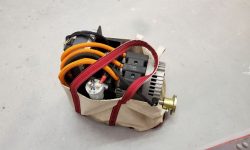
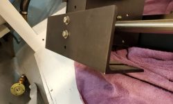
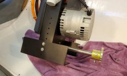
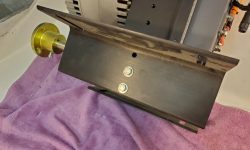
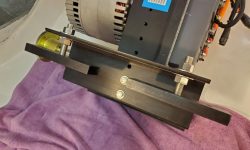
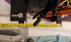
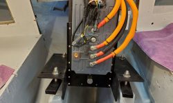
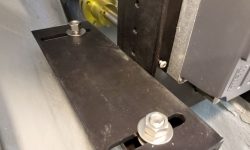
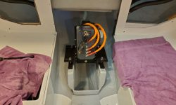
To bring the electric motor assembly into the boat, I found it handy to put it in a large tote bag, which made carting the weight up the ladder less awkward. Once in the boat, and after familiarizing myself with the basics of installation per the instructions, the first thing I needed to do was reorient the mounting flanges, which could be positioned in various ways and at various heights to accommodate many different installation scenarios. For this boat, I needed to turn the mounting slots outward (to accommodate the 11-1/2″ mounting centers of the existing foundation), and, based on a rough measurement of the shaft height, I thought I needed to turn the flanges over so the actual mounts would hang beneath, giving the motor something approximating its correct height vis-a-vis the prop shaft. These changes were straightforward and served as a starting point, though I knew various adjustments would be needed.
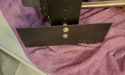
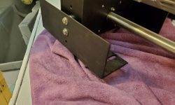
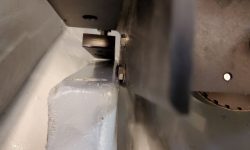
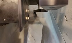
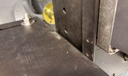
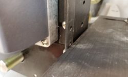
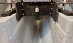
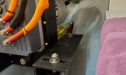
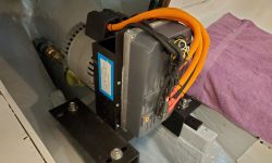
With the flanges realigned and the mounting feet loosely secured where my eyeball roughly thought, I tried the fit on the foundations, but immediately had a problem: The L-shaped mounting brackets, secured to the engine unit with bolts and spacers, were a bit wider than the inside of the foundation, and the engine had to sit down within the space a bit because of the position of the shaft.
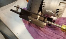
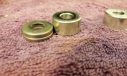
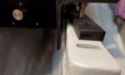
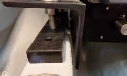
The first fix seemed just to be to reduce the width of the spacers (the purpose of the spacers is indefinable, but I wanted to try and keep them). On hand I had some extra-thick 5/16″ washers, two of which were about half the thickness of the original spacers, so I installed them and tried again. However, this was still too wide to fit as is.
Now I thought I’d try the flanges without any spacers at all, which led to a related minor issue with the motor: The little L-shaped brackets on the front of the unit, which accepted the front cover (not in place here) and screws, extended down just below the mounting flanges, which would prevent them from being secured tightly to the motor housing if I removed the spacers (this may be the only point of the spacers, come to that). That would be an easy fix if needed, so for now I simply removed these two brackets, then attached the L-shaped flanges directly to the motor housing.
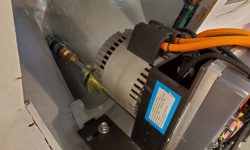
Now everything fit between the foundations, but the whole engine was a bit low, as evidenced by the way the two shaft couplings were misaligned. That was to be expected and represented minor adjustments. Now, the electric motor assembly is a lot lighter than a diesel or gas engine would be, and isn’t too bad to move around, but still, one hopes not to move it on and off the engine beds too many times in the course of an afternoon. This had already been quite a bit of moving around so far.
It was late in the day and I’d been determined to have the engine sitting on the foundations by the end of the day, but as I made some height adjustments to bring the couplings into alignment I realized that I’d have to realign the L-brackets differently, as the engine was ending up too high on the mounting studs, right at the top so far and the engine wasn’t yet adjusted correctly.
This was no particular problem, but by now it was too late to consider removing the engine and starting over, so I left that task for next time, when I’d determine how best to position the L-brackets and then get the engine properly set up and at the right height.
Total time billed on this job today: 7.5 hours
0600 Weather Observation: 36°, light rain. Forecast for the day: Showers and rain, 45°, becoming sharply colder overnight


