

March 4, 2021
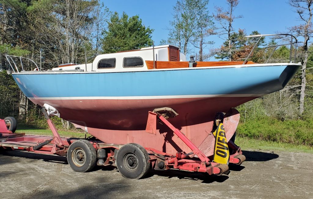
Lyra 31
Thursday
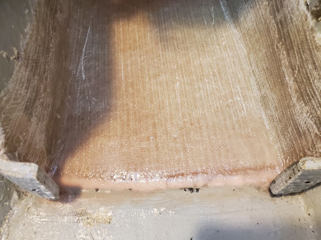
The newly-glassed house battery platform in the engine room required a light sanding to ease any sharp edges and remove some fiberglass shards at the ends of the platform.
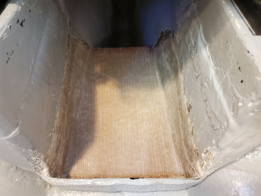
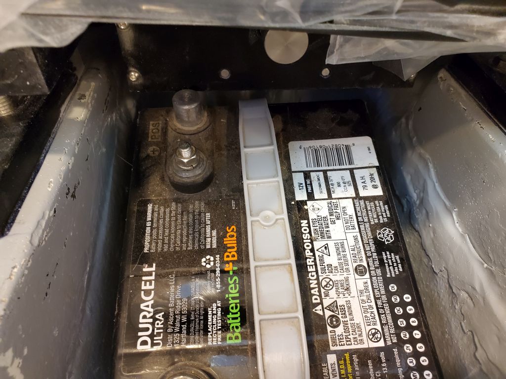
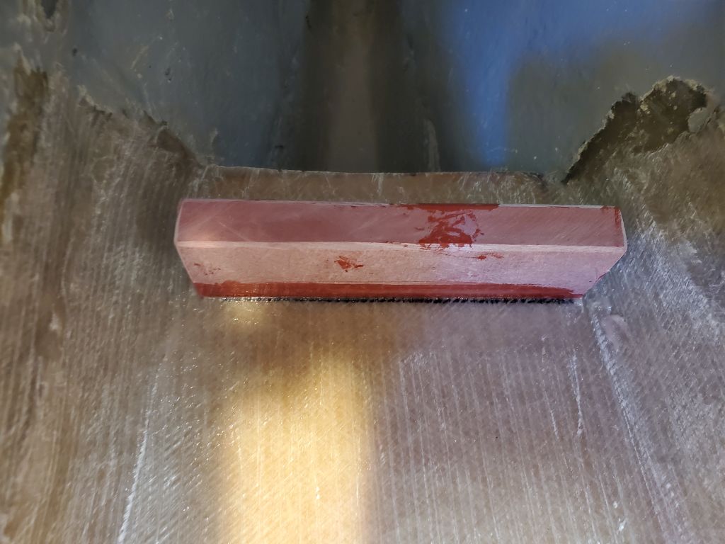
Afterwards, I thought I’d try the actual battery to check the fit. To my horror, I couldn’t get the battery in: The angle required to twist the battery over the fiberglass end of the engine foundation was such that the battery wouldn’t slip into place on the platform. I was sure (so I reassured myself) that the battery would fit: I’d measured it nine ways to Sunday. But the height of the battery increased enough during the installation over the fixed end that it wouldn’t drop down onto the platform.
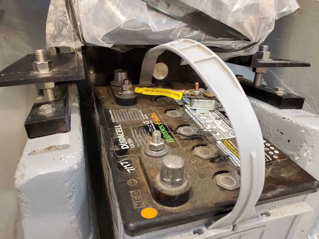
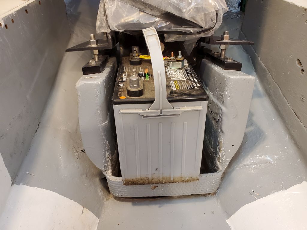
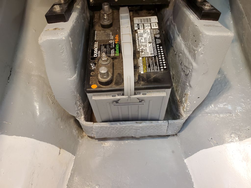
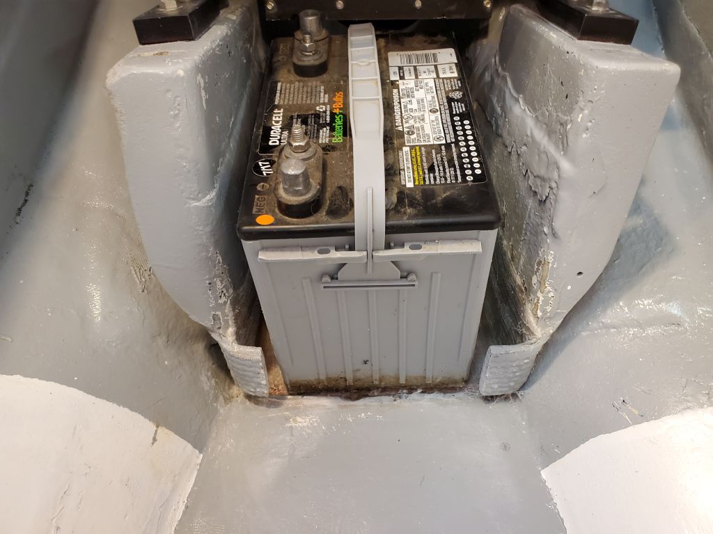
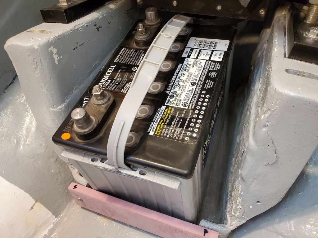
I knew the battery would fit once it was in there, so fortunately this was a straightforward fix: I cut out a battery-sized section of that transverse strip that allowed the battery to slide into position on the flat, after which it fit as expected with ample clearance at the aft end between the terminal and the electric motor housing above (more than the photos make it appear), vindicating myself.
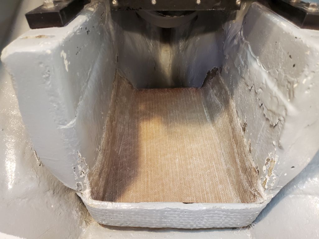
Since I’d planned for that fixed strip to act as the forward fiddle to help secure the battery, I made up a new, removable fiddle from 1/2″ prefab fiberglass and secured it to the tabs remaining from the original with machine screws in tapped holes; there was enough room behind to add nuts and washers later, but no need for now. At the aft end, I cut another section of fiberglass to form the fiddle for that end, as planned from the getgo.
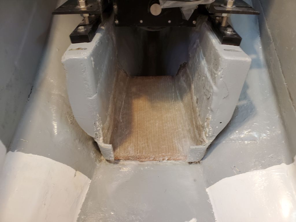

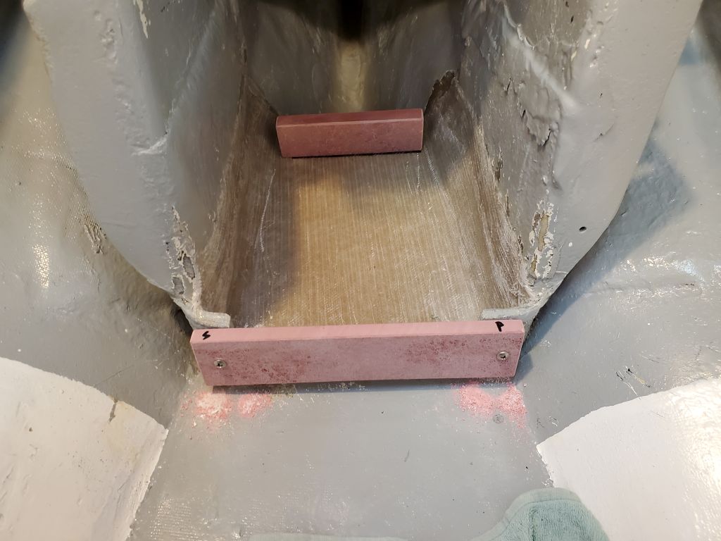


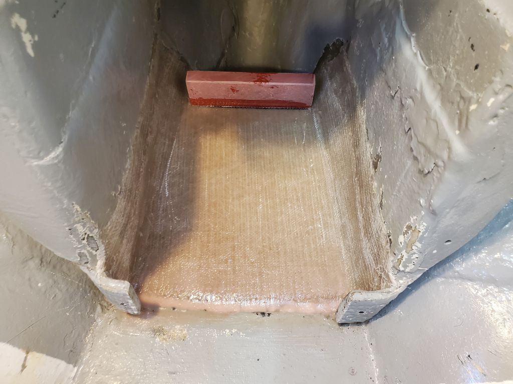
After final preparations, I glued in the after fiddle with epoxy, and used some of the excess to smooth over the transition between the platform and the cabin sole at the forward end.

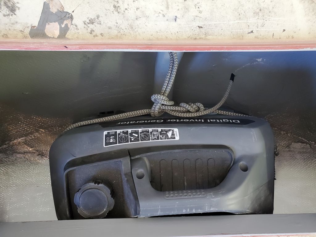
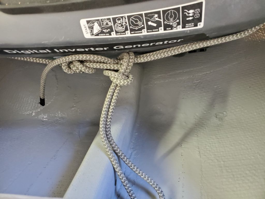
Moving on, I finished up work in the generator storage compartment in the lazarette. To secure a lashing line, or perhaps a ratchet strap, either of which would hold the generator securely, I installed a pair of padeyes to the original plywood backing on the aft cockpit bulkhead. The generator fit snugly on its own, and the lashing would ensure that it wouldn’t tend to move at all.

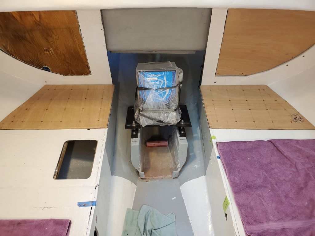
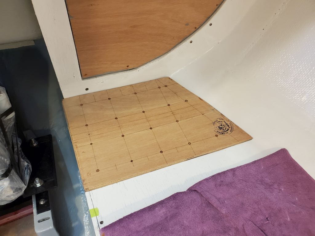
In the cabin, I installed the 12mm plywood “subfloors” for the battery boxes on the settees on either side, securing them with screws in a grid pattern I laid out beforehand. The multiple screws ensured that the extra layer of plywood would work as one with the settee beneath. Later in the day, after removing a partial splintered wood cleat and old nails leftover from the original galley on the starboard side (I hadn’t known this stuff was still there when I’d painted the interior earlier, so I painted over it), and after I was sure I was done with work in the boat itself, I applied a coat of primer to the bulkhead filler panels and the new work on the settees.


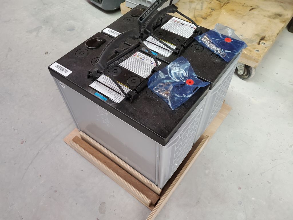
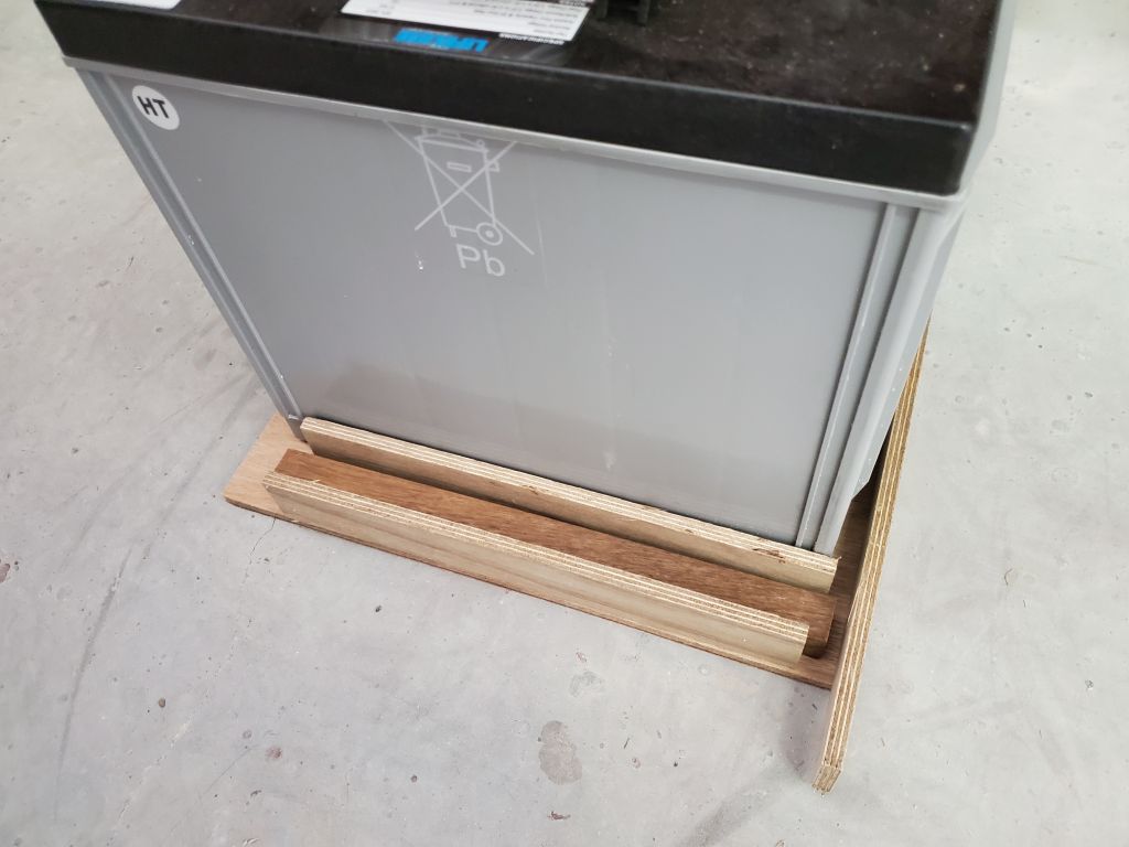
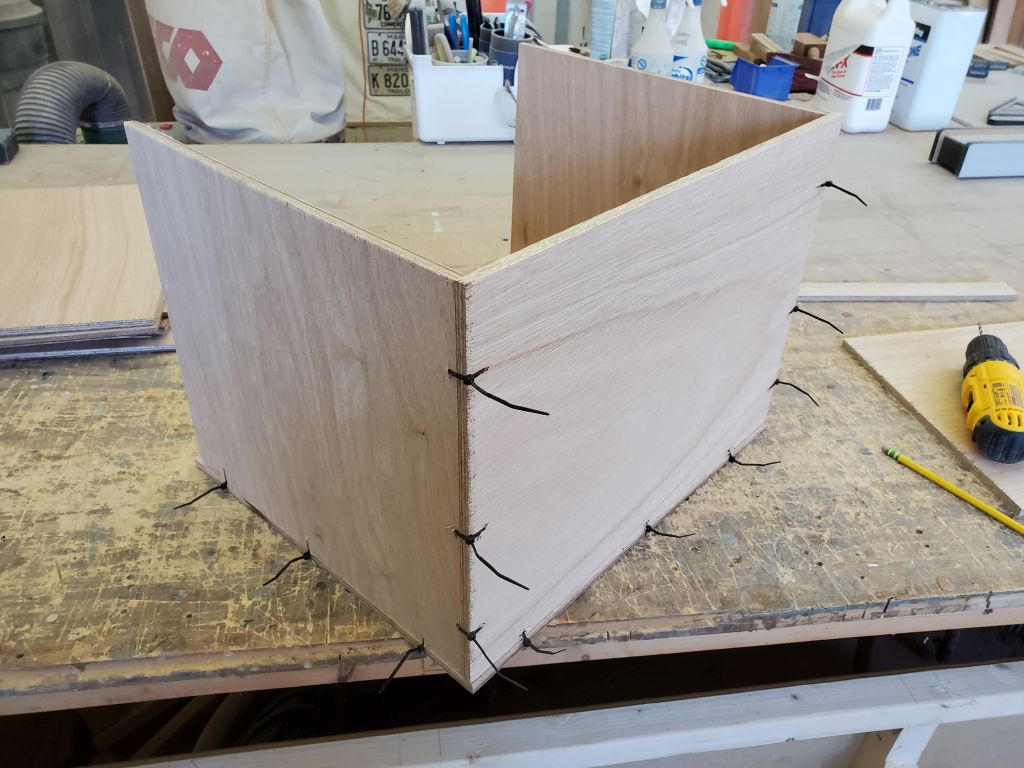
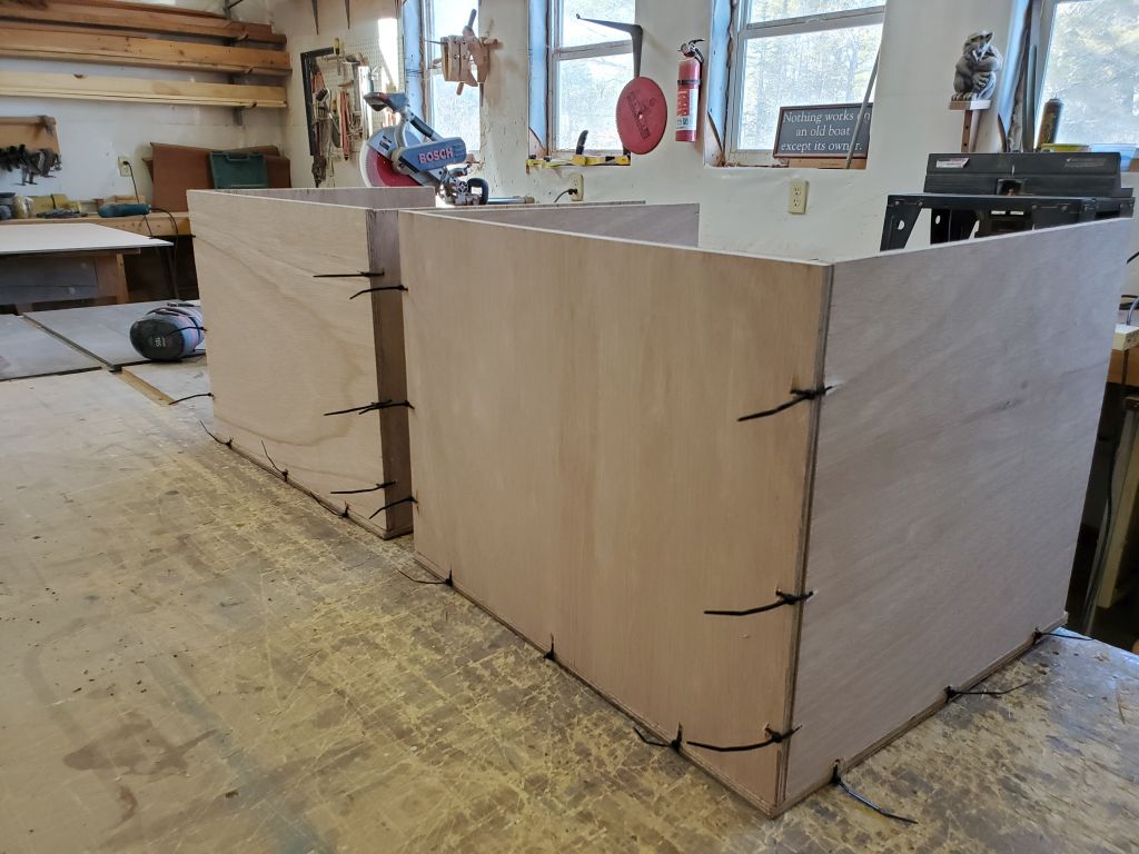
With all the battery location and related questions now answered, I spent the rest of the day building the battery boxes to hold and secure the four AGM batteries for the engine bank. Because there was no direct overhead access to the battery locations, and given the weight of the batteries (100 lb each), I designed the boxes to accommodate installation (and someday removal) through the fronts of the boxes, along with traditional top access for inspection, wiring, and maintenance. For this, the fronts needed to be removable, yet secure, so my design featured hardwood cleats on each side of the box and, to provide security for the batteries within, a second wall on the inside of the cleats to cover them and give the batteries a bearing surface. So with all this in mind, I eventually sized the bottoms for the boxes accordingly, cut one to size from 9mm plywood, and test-fit a pair of the batteries along with mockups of the sides and back.

Satisfied with the basic size as defined by the test bottom, I cut all the remaining plywood to build two boxes, then assembled them with small holes and plastic zip ties to secure the pieces together. For this assembly, only the bottom and three sides were necessary, as the fronts would remain removable; the cleats and “inner sides” would also be installed later.
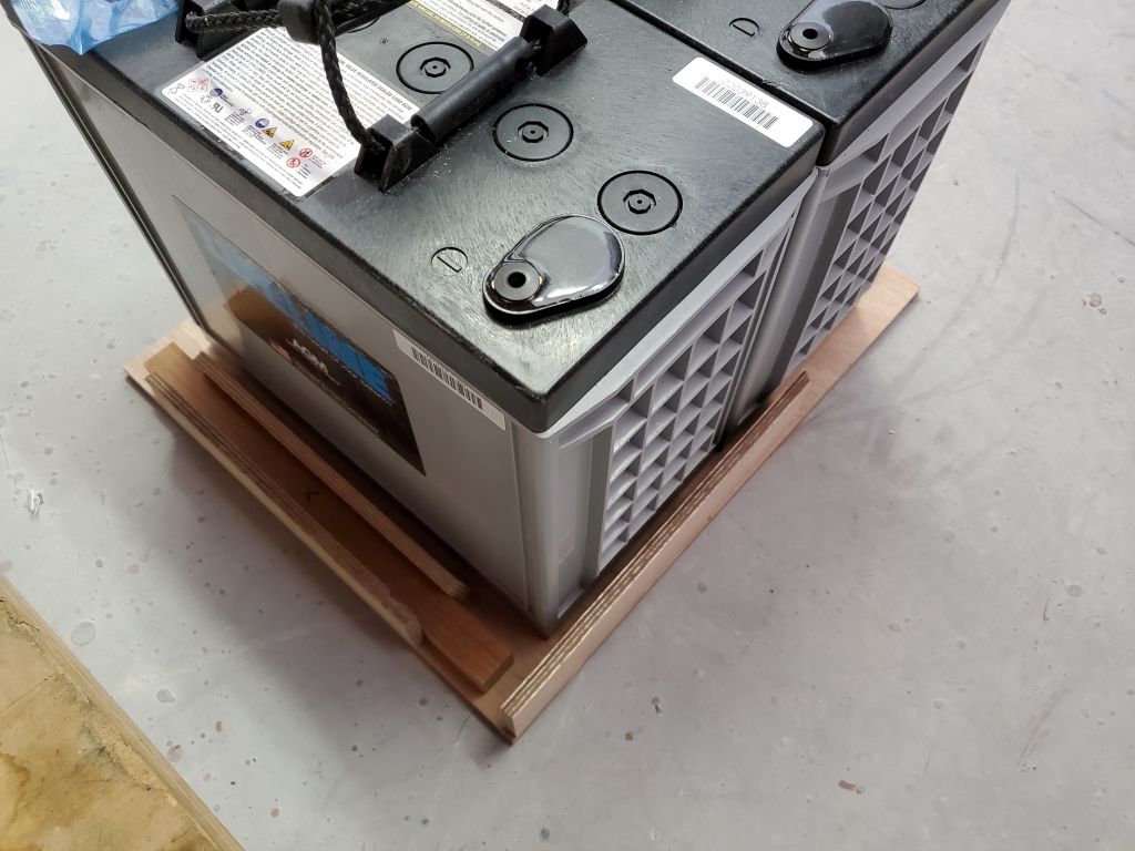
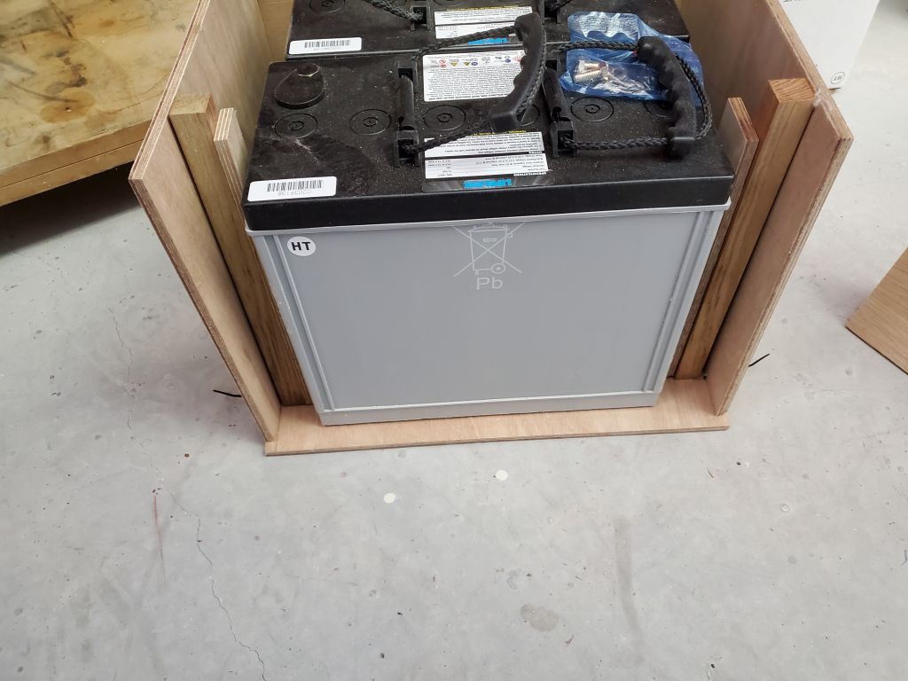
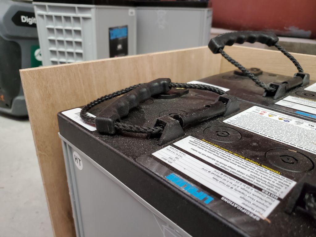
With the boxes dry-assembled, I checked the fit once more with the batteries and the full mockups of the sides, with their 1″ square hardwood cleats and an inner layer of 9mm plywood. Above the batteries, I left substantial clearance to allow for the handles to lie flat and room for terminals, wiring, and so forth.
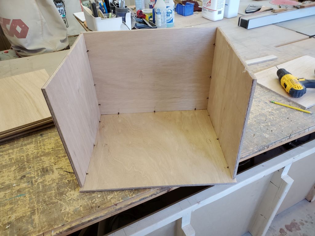


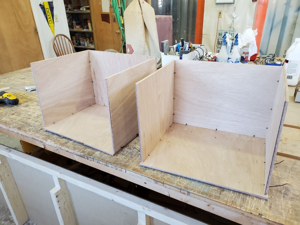
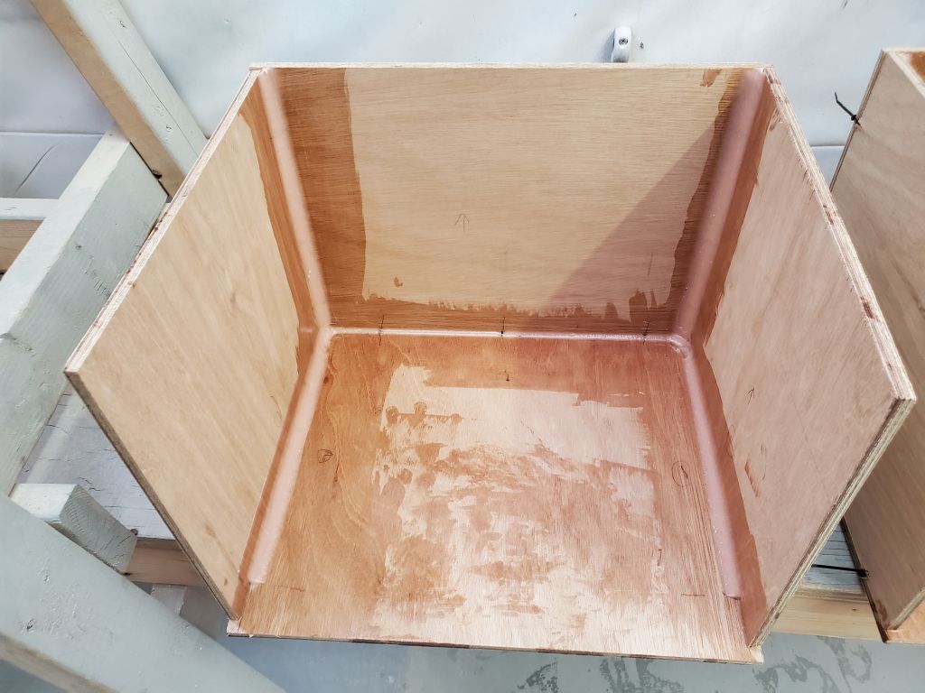
Next, I installed epoxy fillets inside the boxes to secure the pieces together permanently, and left them to cure overnight. I kept the fillet at the corner between bottom and back fairly small so as not to impede the batteries’ flat stowage within, and stopped the side fillets roughly 1″ short of the front to allow a full-sized cleat to be installed there. (I’d shorten or modify the two other cleats for each side to fit around the fillets.)
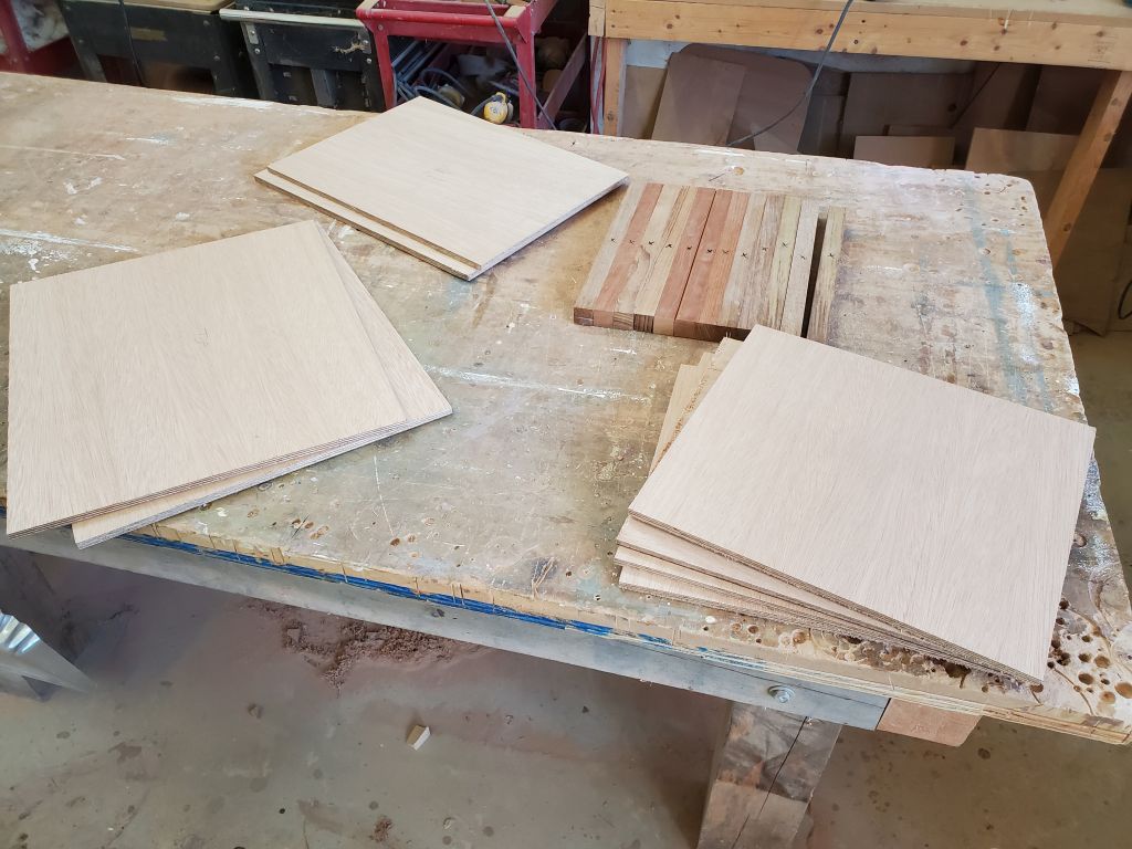
Finally, I cut, from 9mm plywood, the pieces I needed for the inner sides, the tops, and the fronts of the boxes, along with a few additional 1″ cleats, which pieces I’d left till now so I could concentrate on getting the main shells of the boxes assembled and glued before the end of the day.


Total time billed on this job today: 6.5 hours
0600 Weather Observation: 22°, clear. Forecast for the day: Sunny, 34°