

March 3, 2021
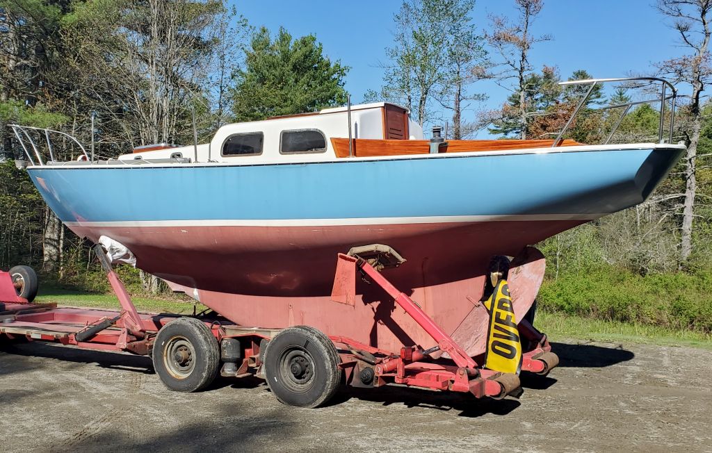
Lyra 30
Wednesday
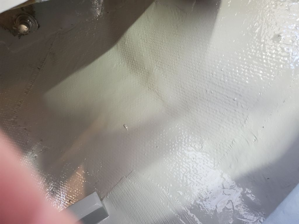
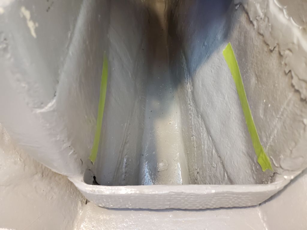
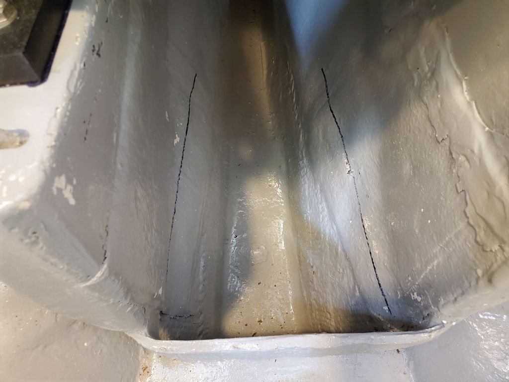
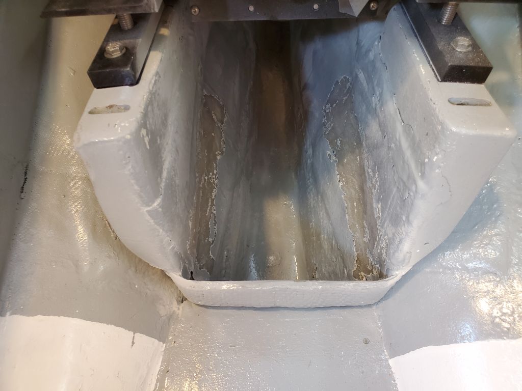
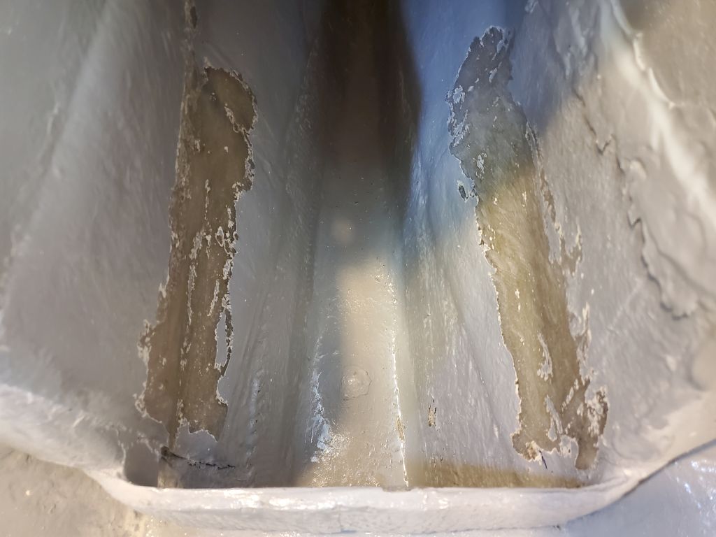
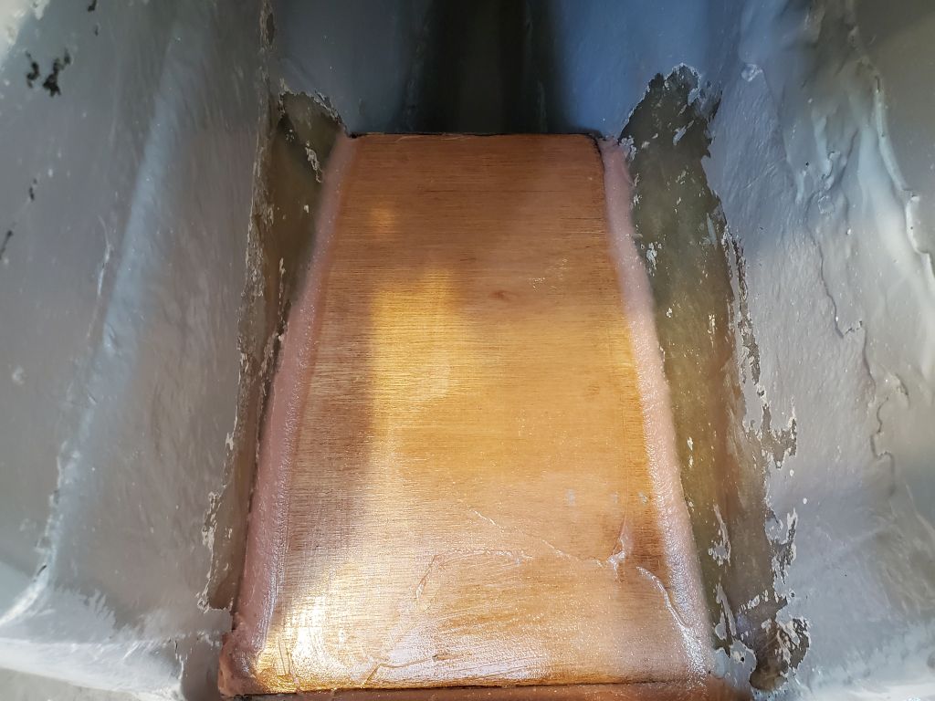
After some final cleanup in the generator locker, I applied a coat of the gray bilge paint to all areas and the new work. Because many one-part paints sometimes have trouble curing over fresh epoxy, I’d applied a few test dabs the day before to see if the paint would dry overnight–it did–so I felt safe proceeding without a two-part primer tie coat, which I often used to speed things along.


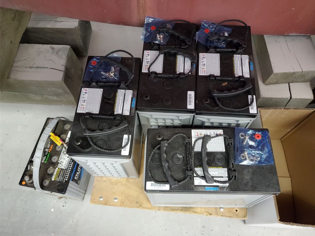
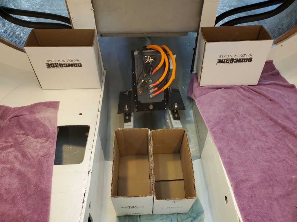
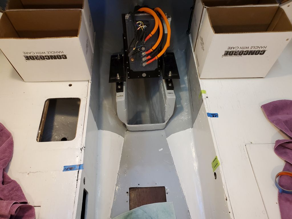
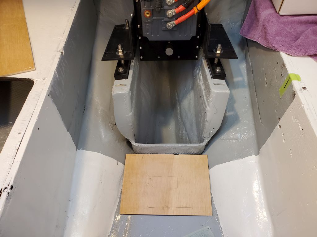
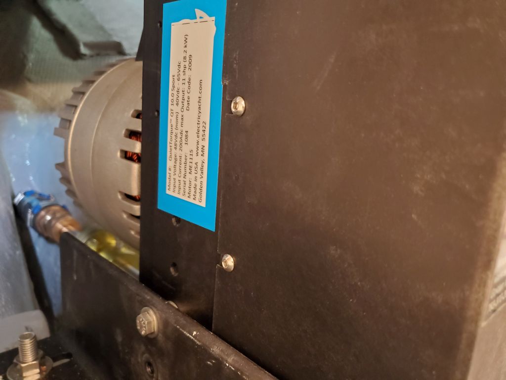
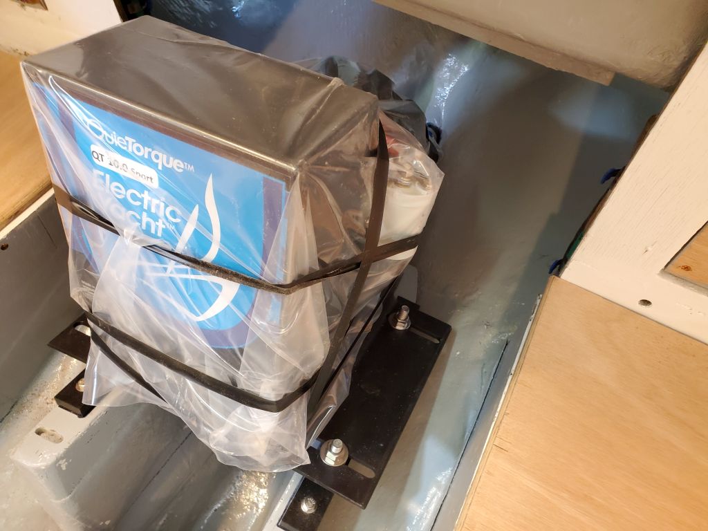
With the electric motor installed, the next matter of importance was the juice for the motor: The batteries. The powerplant required four 150 amp-hour 12-volt batteries to make up the 48-volt bank, and now it was time to finalize the battery locations and build boxes as needed to hold them.
The initial plan the owner and I had been considering had one pair of the batteries in a box just forward of the engine room, which box would end up being part of the companionway ladder and steps; the other two batteries, in this plan, would be located on either side of the engine near the aft bulkhead. But during continuing conversations with the owner throughout the morning, we challenged various aspects of the plan and made changes accordingly.
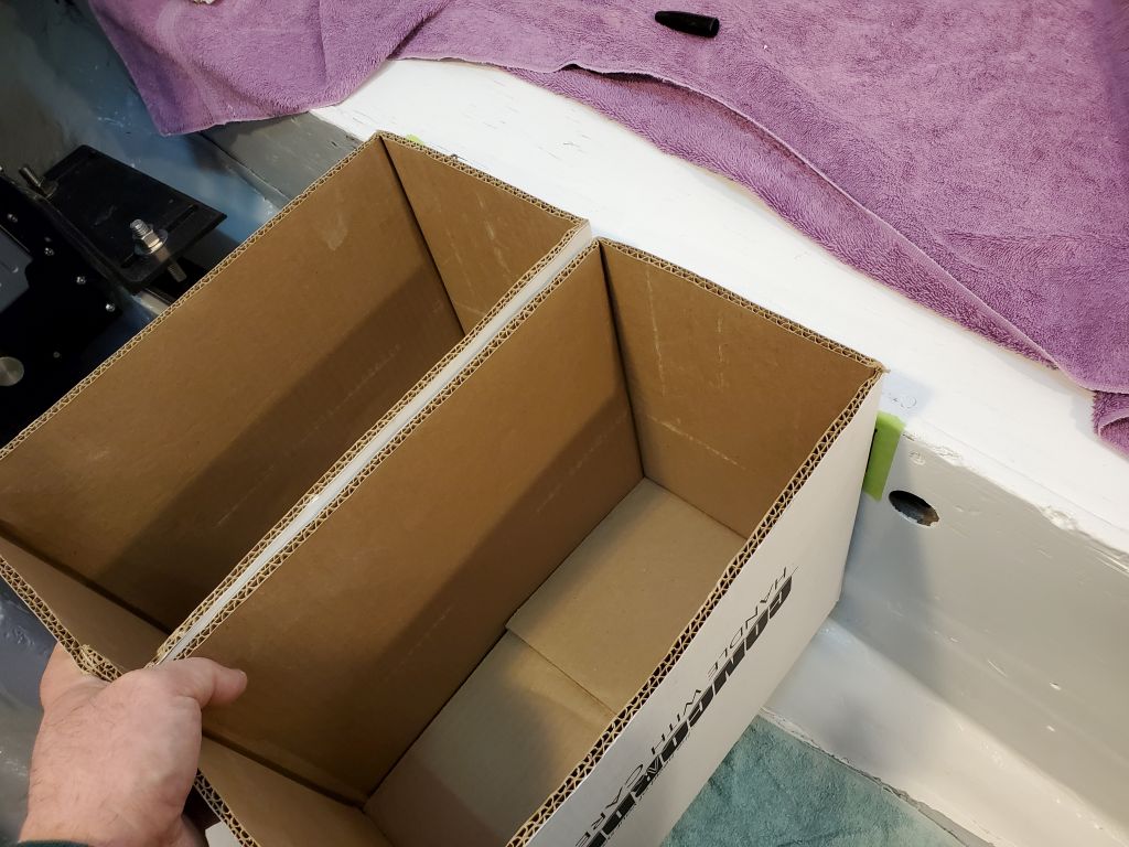
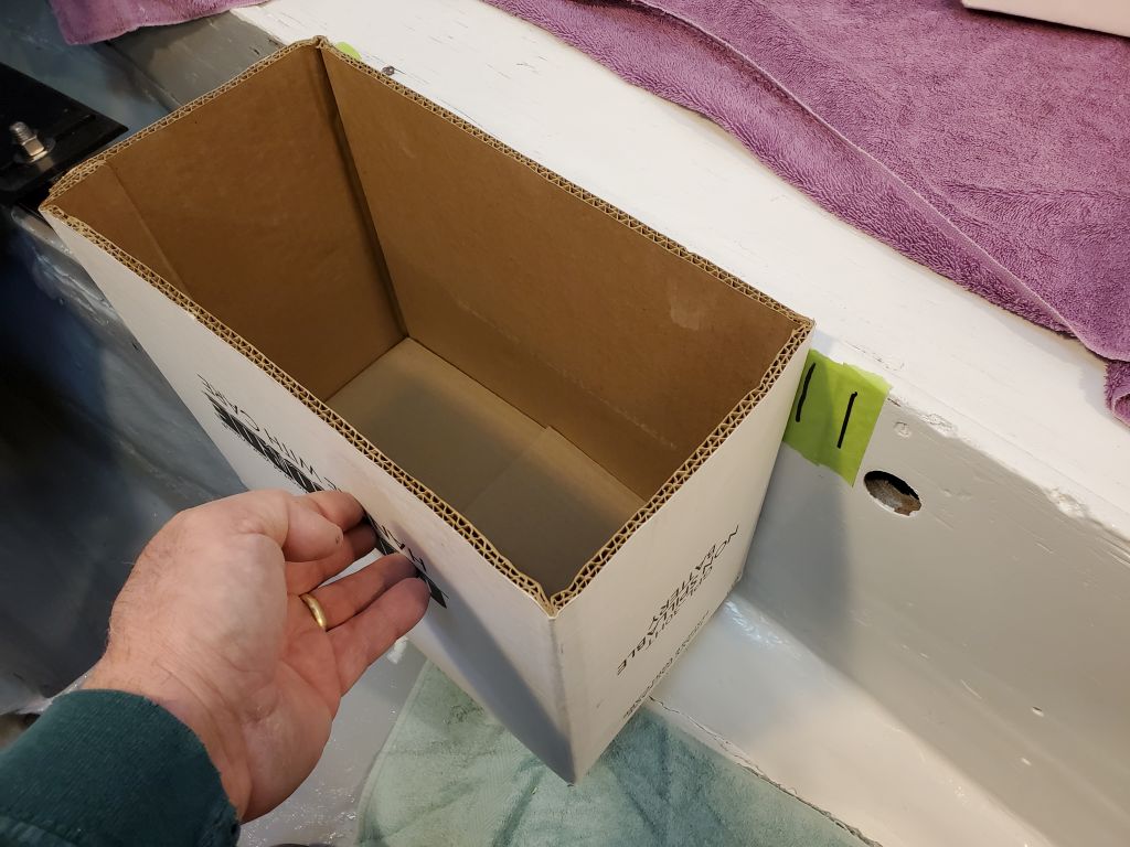
Among other considerations, one of the things I looked at was whether the pair of batteries forward of the engine would take up less room when oriented longitudinally or transversely; it turned out that they were shorter than the pair was wide by about an inch, so if we went this route we’d stick with the orientation as shown above. In the final photo below one can see the tick mark about an inch forward of the box representing the battery.
The owner was loath to give up the cabin sole space required for the batteries in front of the engine, and with further discussions (and here I’d be remiss to fail to mention the brilliance of the owner in coming up with the idea) we decided it would be better–with few real detriments–to place a pair of the batteries on each side of the engine, on the settees forward of the bulkhead. This plan had the benefits of opening up the cabin space, simplifying battery box construction (two versus three), and further simplifying the battery wiring later on. Weight distribution was equal from side to side, and while in a perfect world it would have been nice to locate the batteries somewhere further forward (and even more ideally on the centerline), the realities of the boat and other competing needs were what they were and were well defined, and, as in all things, compromise represented the way forward. In fact, once the decision was made, this battery plan seemed completely obvious and better in all respects.
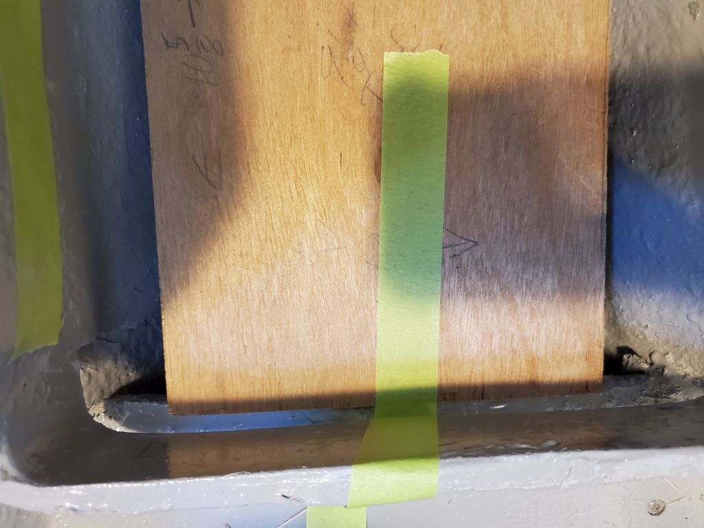
In these photos, the blue tape marks on the settees represent 6′ from the forward bulkhead on each side, the minimum “sleep-able” length for the settees that might drive other aspects of the engine room and galley construction.
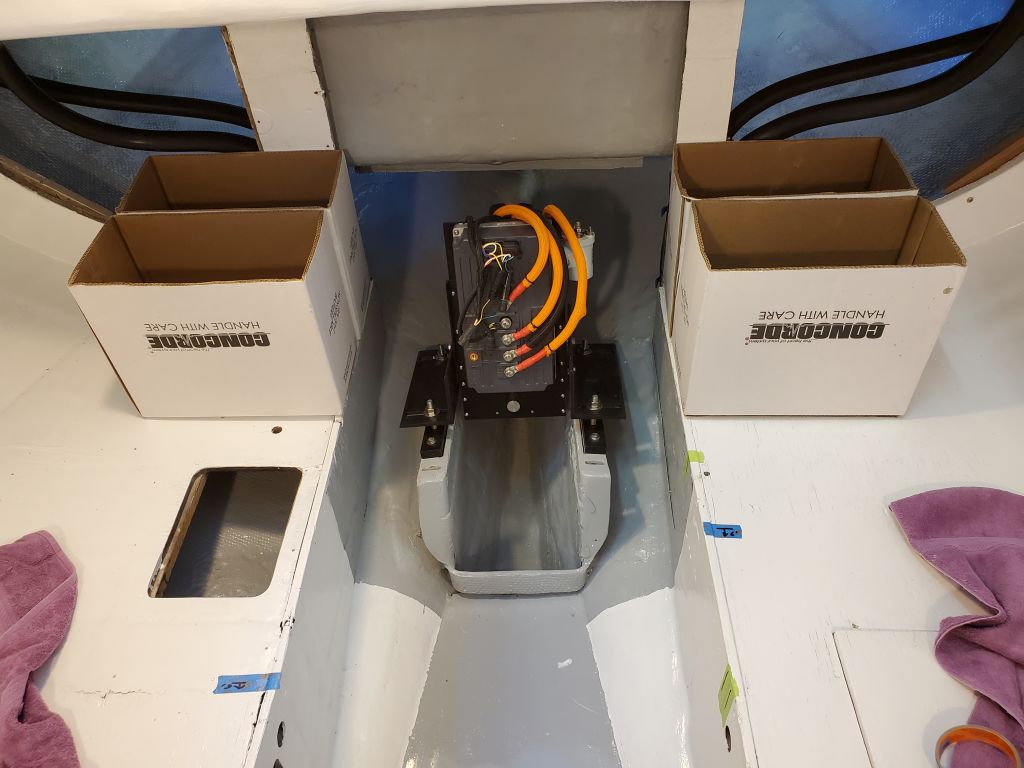
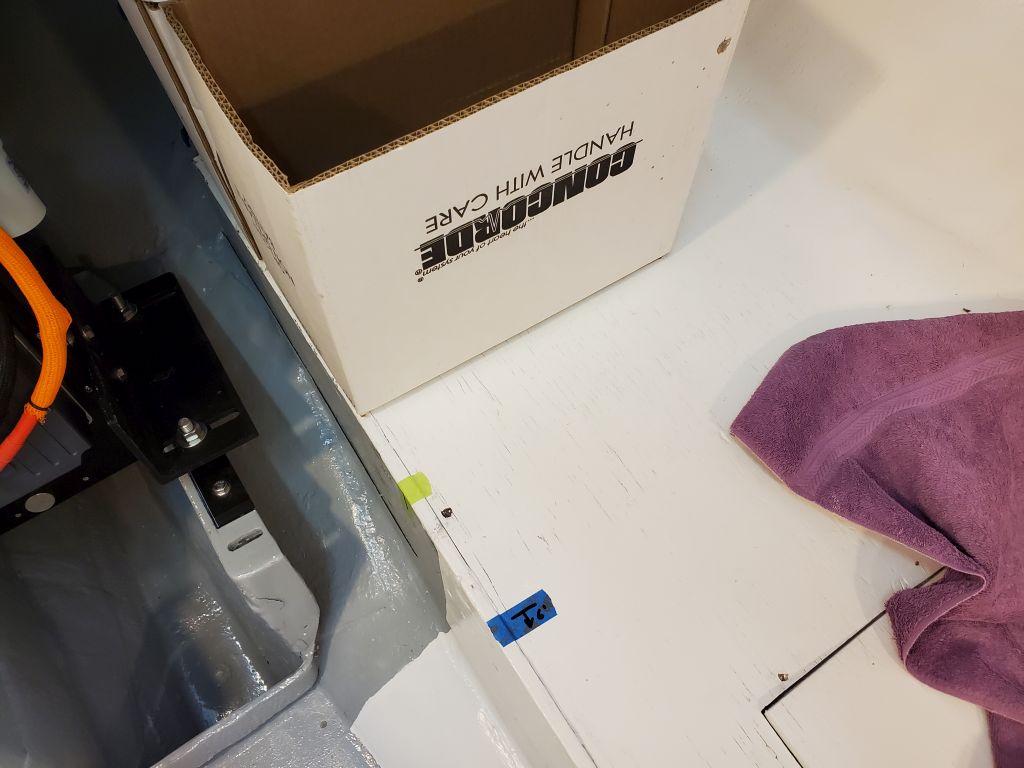
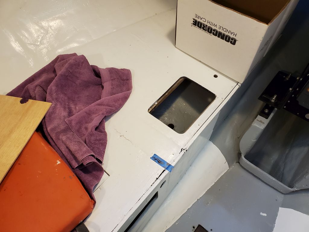
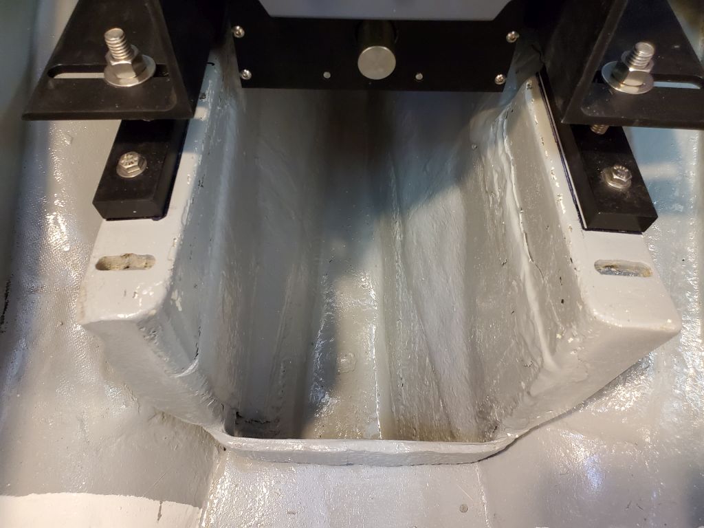
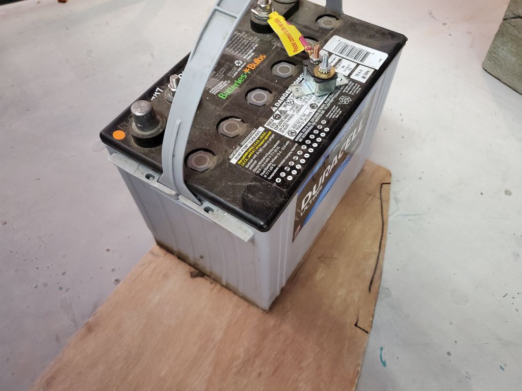
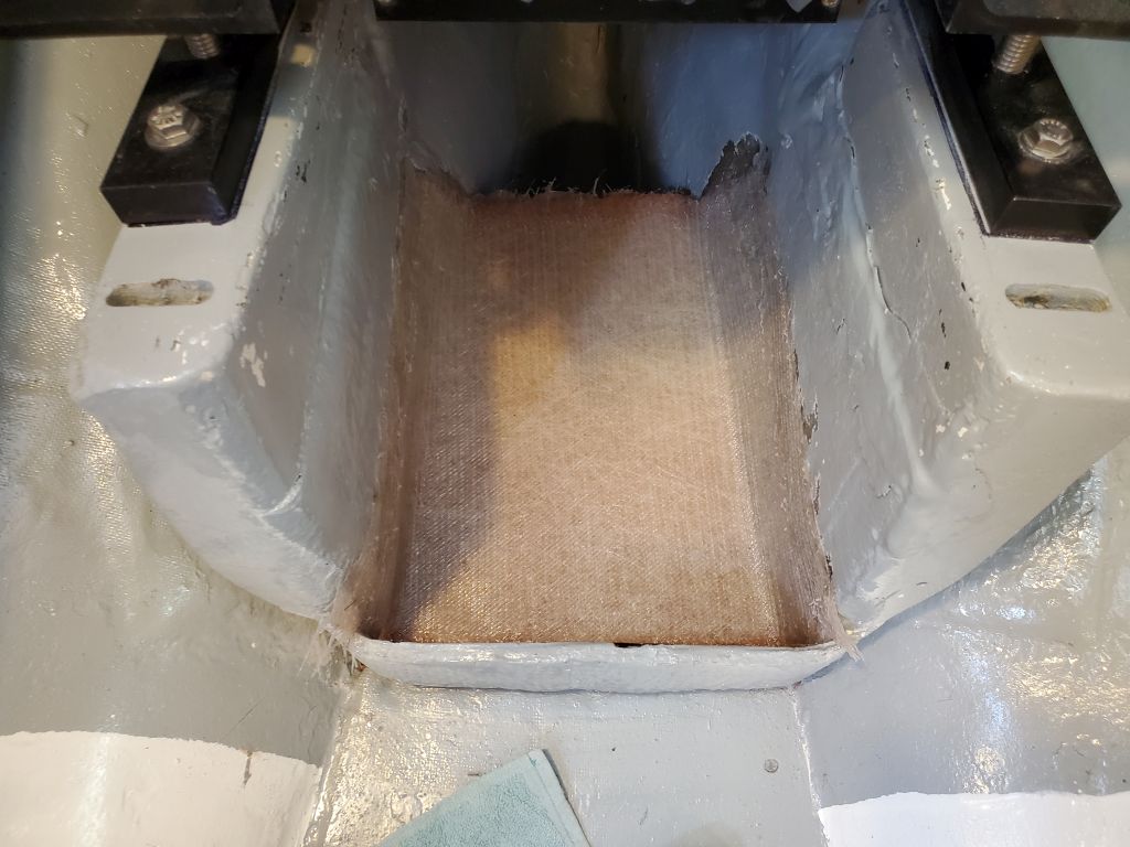
In addition to the engine batteries, the owner hoped to use a single 12-volt standard group 24 battery for the house power, keeping it separate from the propulsion bank. This would be easy enough to fit somewhere, though we’d not formulated an exact plan just yet. But as I worked around the engine space on these other early tasks, my eye kept going to the yawning space forward of the engine between the foundations: It sure looked to me like it was perfectly battery-sized. This would be a great location (thought I) if it worked, and the owner agreed, so I pursued the notion.
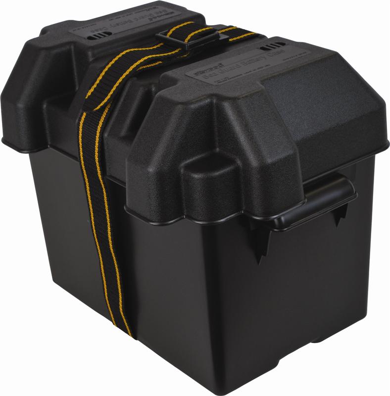
My first thought was to store this battery in a standard plastic battery box for convenience, and I made up a quick plywood template sized according to the overall dimensions of the box, though the 2D template required imagination to turn into the bulky assembly that would be the full box with its vented cover, which was larger than the template I made–but it’d be clear soon enough if it would fit.
It was immediately clear that the prefab box would not work in the space: It was too tall, and the top was far too bulky to fit in the narrow space, with nowhere near enough clearance to the bottom o the engine and the forward end of the driveshaft. The base of the box, for which the template was sized, was too wide and thus sat too high in the bilge thanks to the curves of the hull beneath.
A quick test showed that the box would fit in the space forward of the foundations, but who wanted that–we’d just cleared that space thanks to the new engine battery plan, so this was a non-starter (though it never hurts to have workable alternatives in hand).

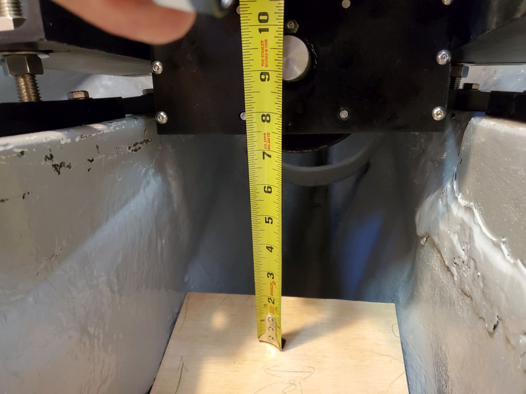
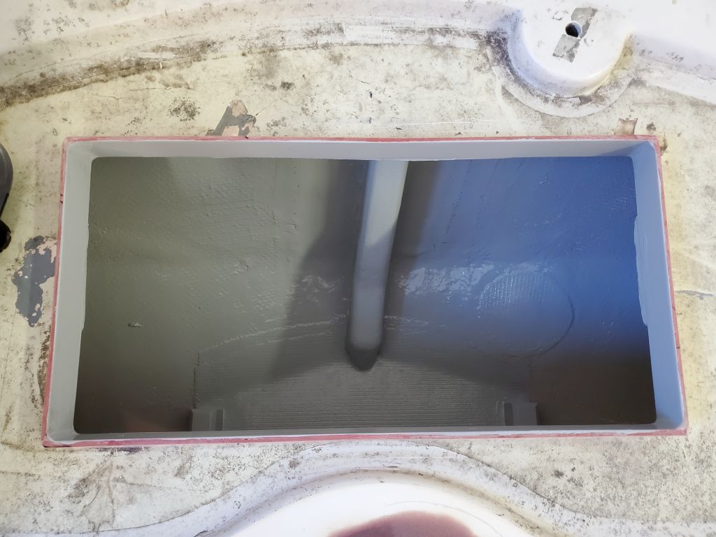
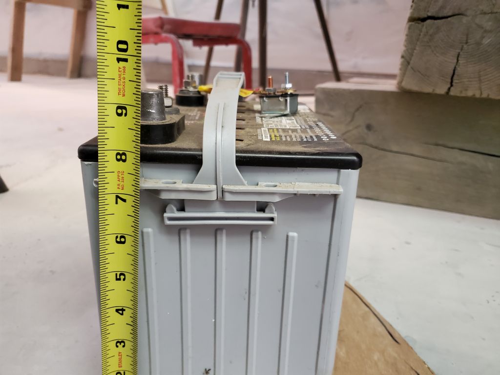
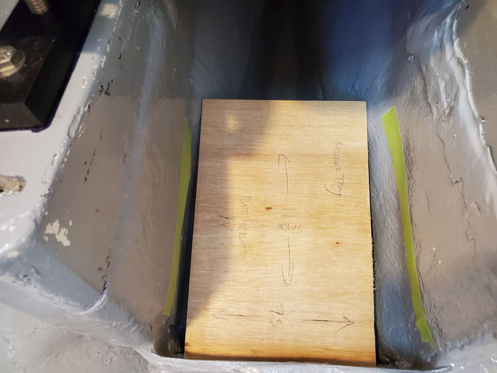
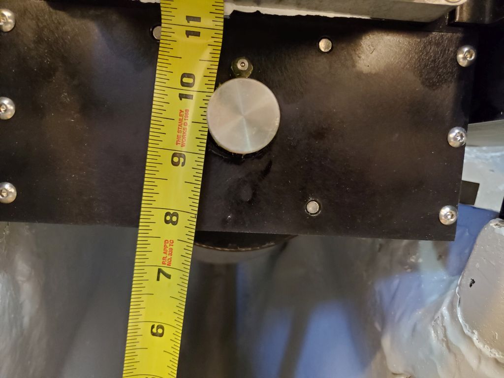
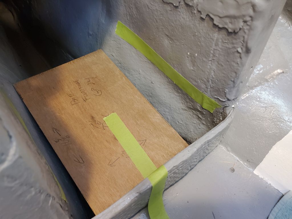
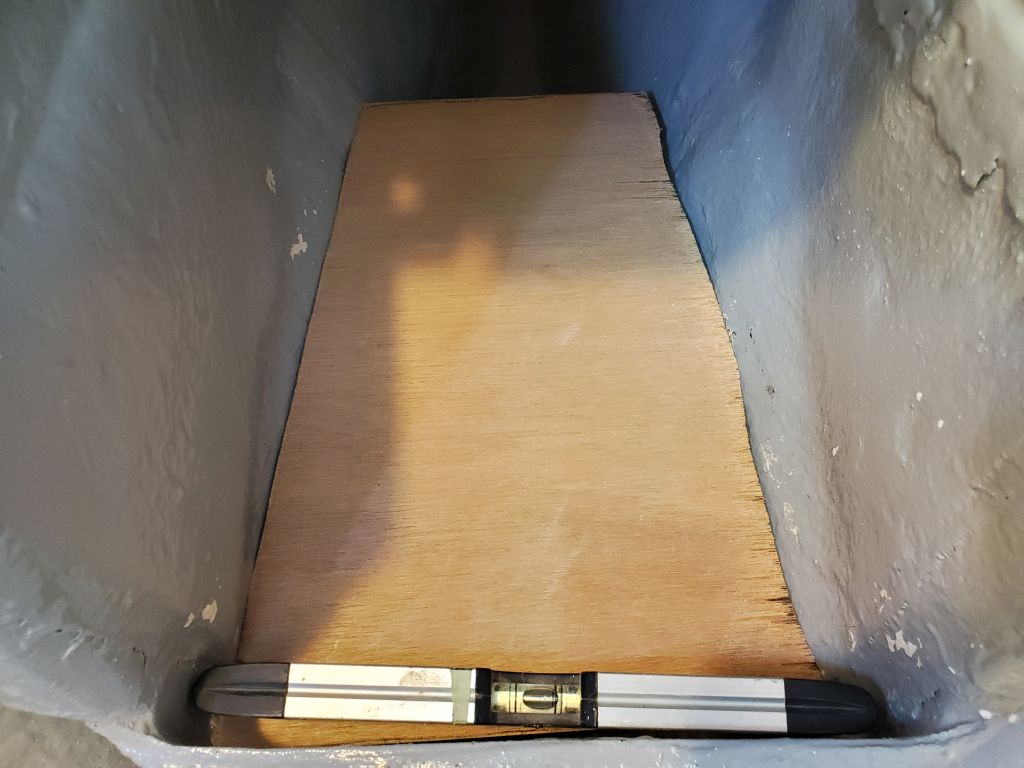
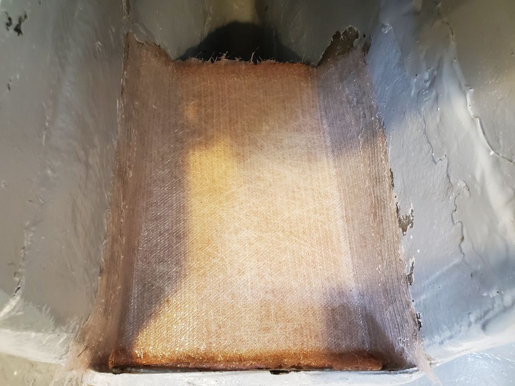
Next, I made another template to the size of a simple battery tray, one of those plastic ones with the hold down clamps or straps. At the same time, I made another template of the actual battery footprint, just so I’d have that reference as well since now the battery dimensions themselves (especially height) would drive the final solution. The battery was 9-1/4″ tall to the top of the terminals.
Again, the plywood template for the prefab base was just a touch too large, and wouldn’t fit low enough in the bilge to allow a safe clearance overhead. While it was almost OK, it was a touch too close to the underside of the engine and the shaft end.


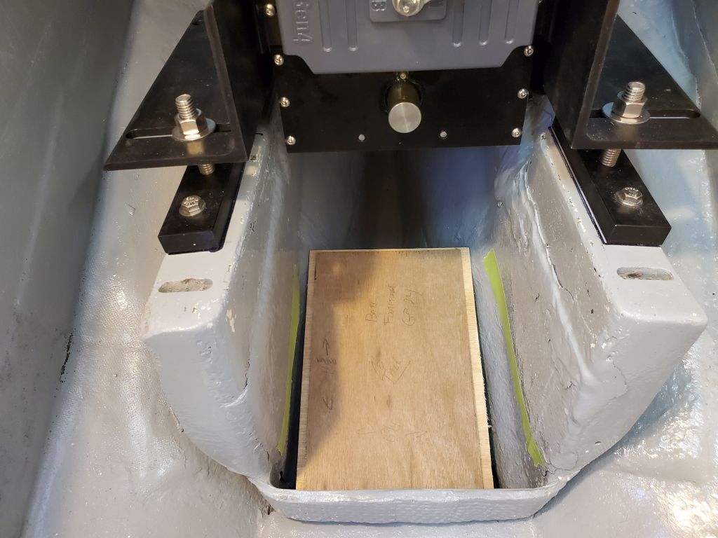
However, all was not lost: the fit was so close with the prefab base that it was a natural progression now to simply use the battery base itself as a template, and if I planned a minimally-sized platform based on that, the battery would fit–which matched what my eye had told be earlier in the morning. This plan just meant that I’d rely on cleats (the forward section of the engine foundation would act as a forward cleat) and a strap to secure the battery to the platform itself, and this proposal would give ample clearance overhead for the battery, terminals, and any wiring.
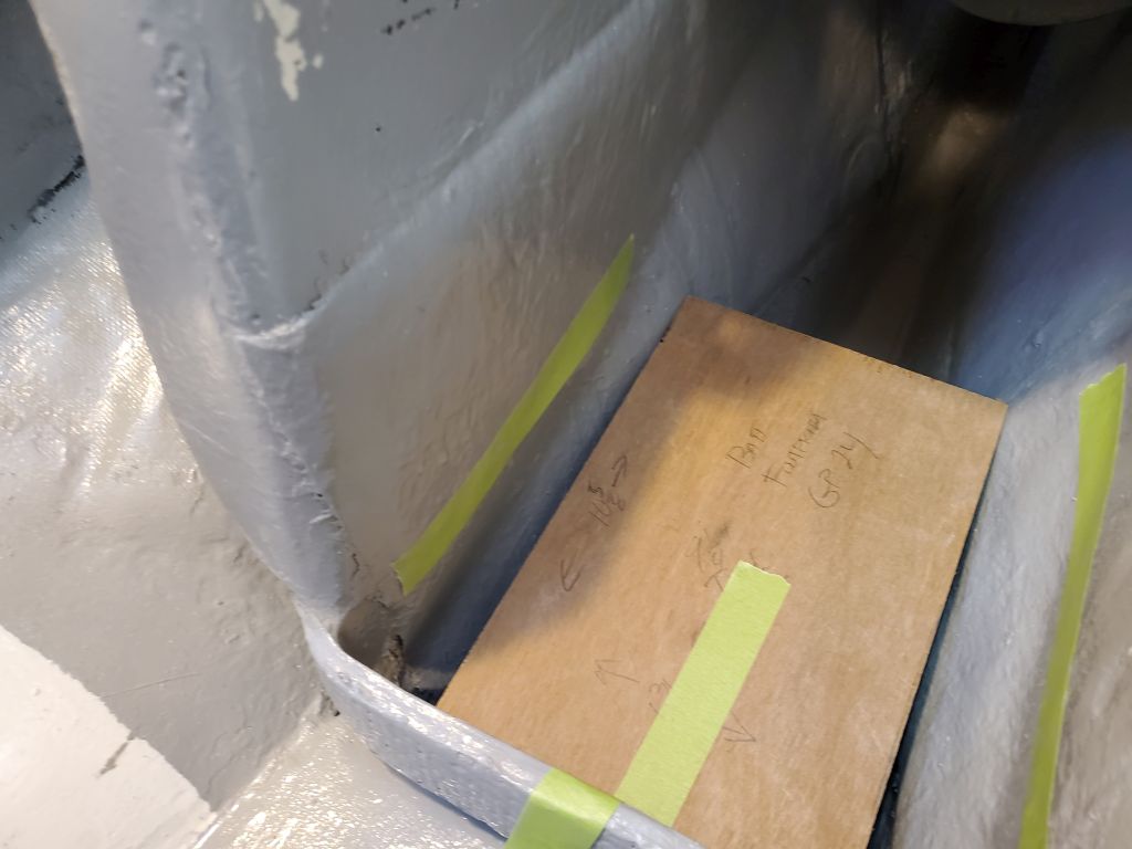
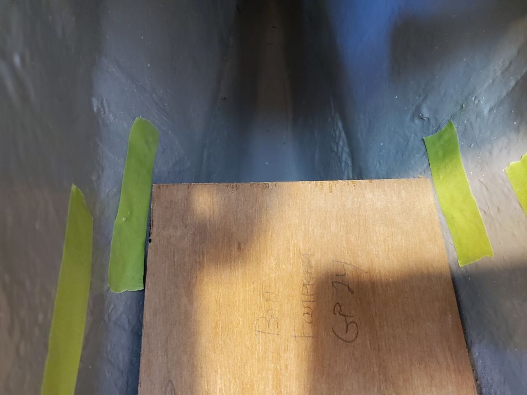
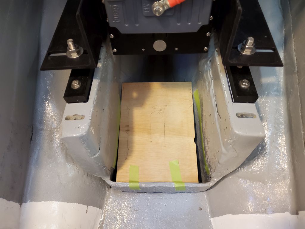
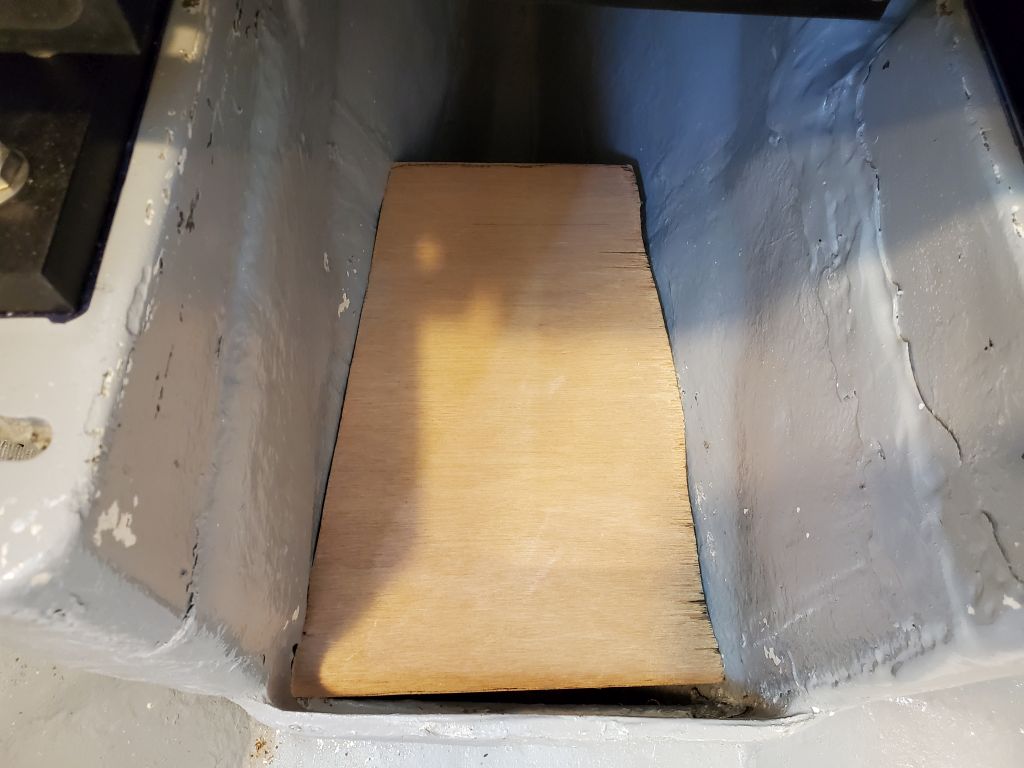
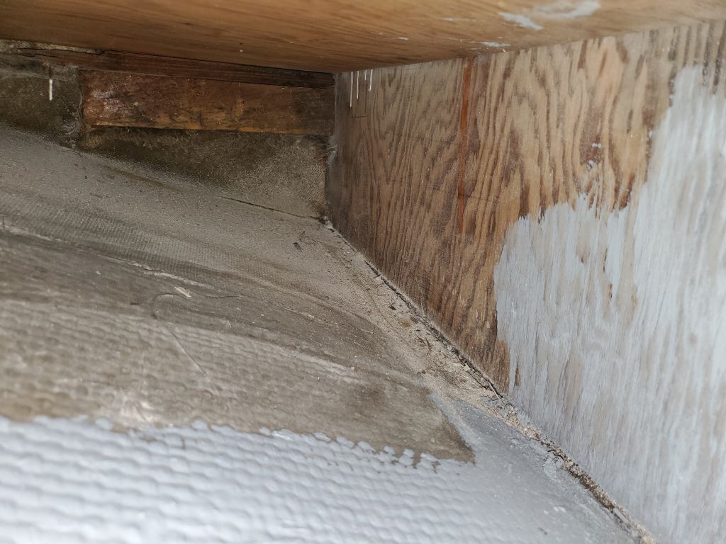
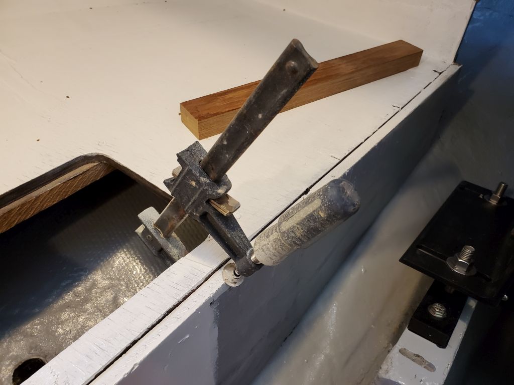
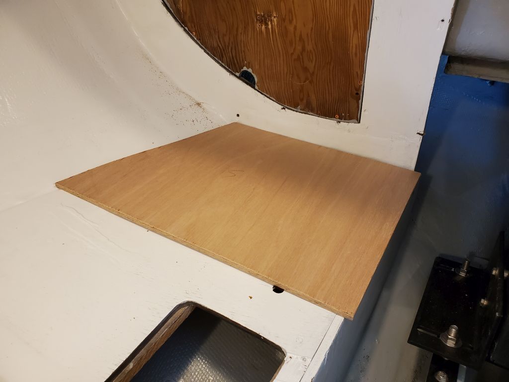
The owner agreed with this plan, so now I could get started on the actual construction. Using my battery-base template, I scribed the shape of the hull and transferred the pattern to 12mm plywood, which I cut to fit. The vast undulations on the port side are from the original tabbing securing the foundations above. I’m frequently amazed at how much work it must have taken Pearson to install tabbing and other fiberglass work with such roughness and bulginess, as if they were trying to make it as awful as possible–a real art form in itself, I suppose.
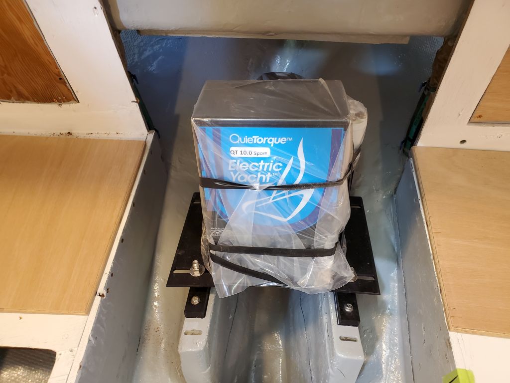
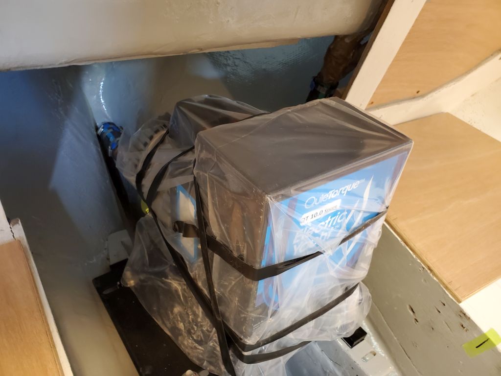
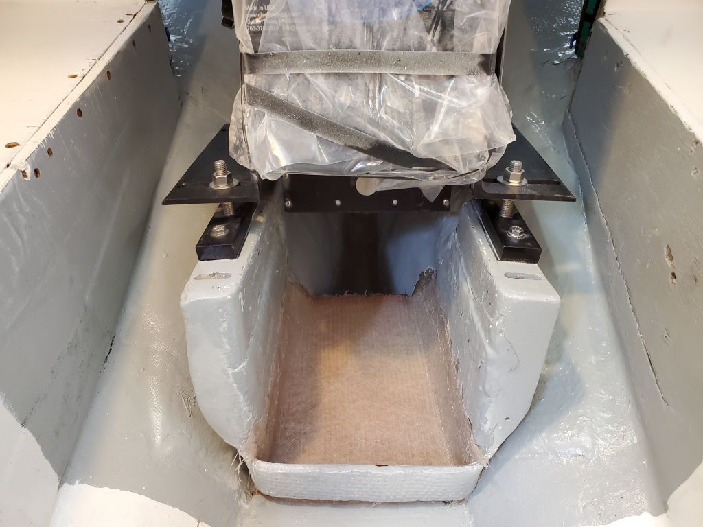
Before continuing, I decided to install the motor front cover for protection, then wrapped the whole assembly in plastic to keep out dust and such during the nearby constructions.
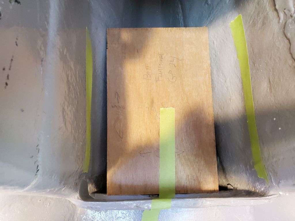
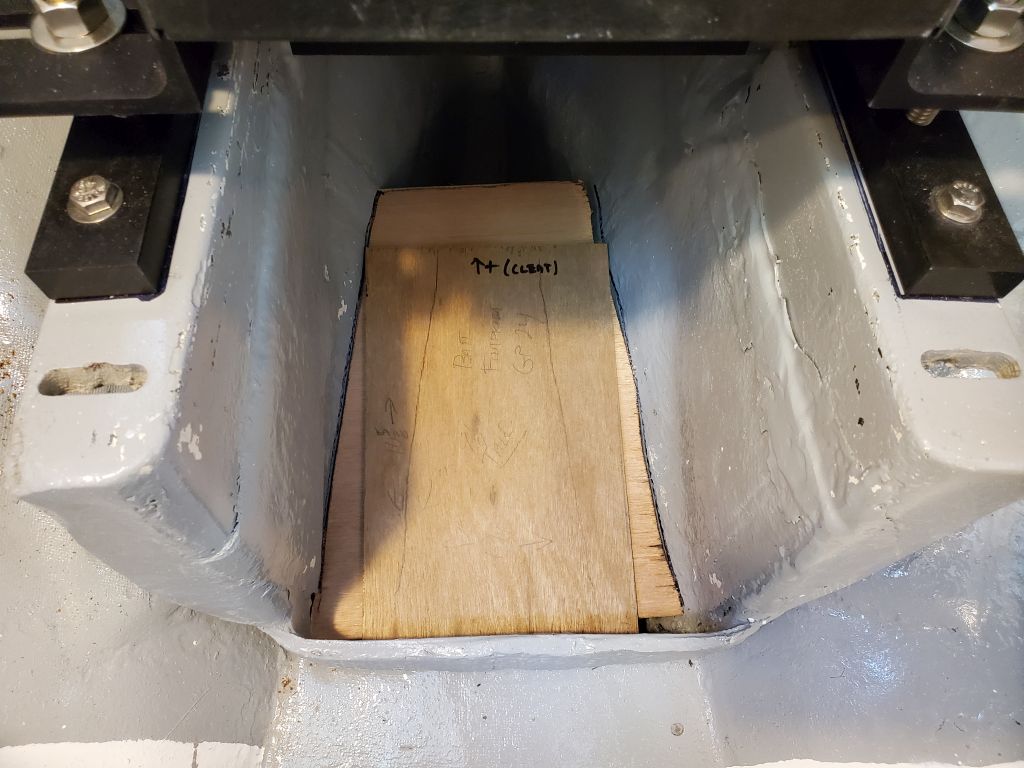
In any event, once I got the platform to fit where it needed to, I marked the hull on each side and sanded away the paint from an appropriate area to allow bonding space for epoxy and tabbing. After cleanup, I epoxy-coated the base and edges of the new platform, then installed the platform with thickened epoxy adhesive and fillets before installing two layers of fiberglass over the top and up the sides of the engine room to fully secure it.

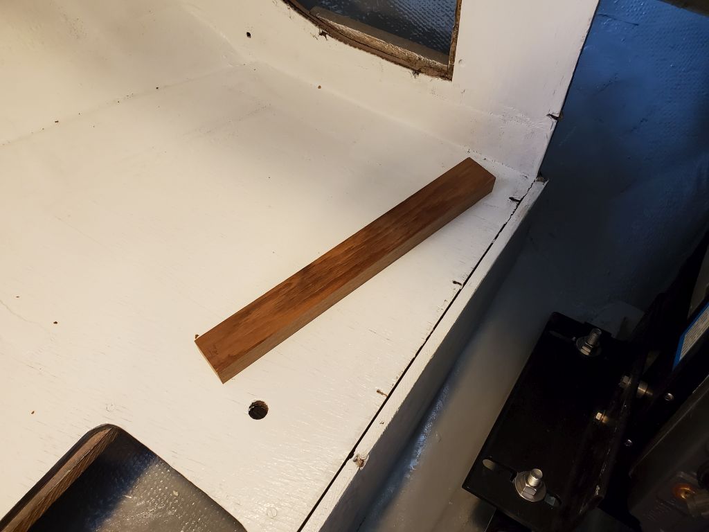
Now I could get back to the propulsion batteries. The starboard settee outboard of the engine room was flimsy where the top met the side, as there was no means of support here–this had been hidden inside the original galley. I had enough access from a nearby cutout that I could install with screws a hardwood cleat inside the space to support and secure the two parts of the settee together, greatly improving the structural qualities.


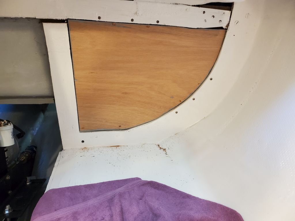
Getting ready for some of the new construction ahead, I installed the two bulkhead filler pieces, using screws to secure each to the cleats behind. I planned to prime and paint the forward-facing sides presently. These were not glorious feats of cabinetmaking, and the original bulkhead was almost comically out of square, plum, and straightness (again, it takes dedication to install something with quite this level of badness–though at least it was strong), but these awful fillers would be completely hidden when all was said and done, and gave at least theoretical access to the spaces behind in the future.


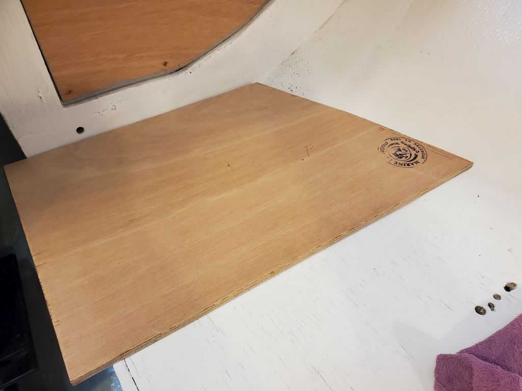
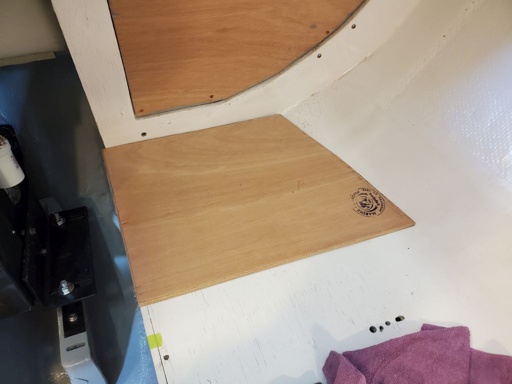
To add additional support for the heavy battery banks–200 lb. per side–I planned to add a secondary layer of plywood over the settees, spanning between the tabbed edges at the hull (strong) and the vertical sides of the settees bordering the engine room (also strong enough). From 12mm plywood, I cut two pieces to fit, each wide enough for the forthcoming battery boxes and long enough to span the settees as needed. I cut the outboard ends to fit the shape of the hull as needed. I planned to screw these to the existing settees, but before doing so and since it was the end of the day, I epoxy-coated the bottom sides of the new pieces for protection (the exposed surfaces would receive primer and paint to match).


Total time billed on this job today: 7 hours
0600 Weather Observation: 14°, clear. Forecast for the day: Partly sunny, 36°