

April 13, 2016
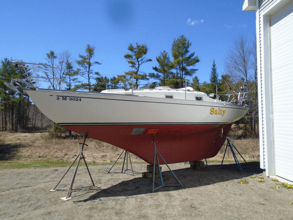
Salty 39
Wednesday
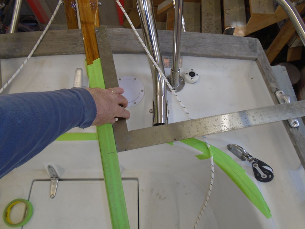
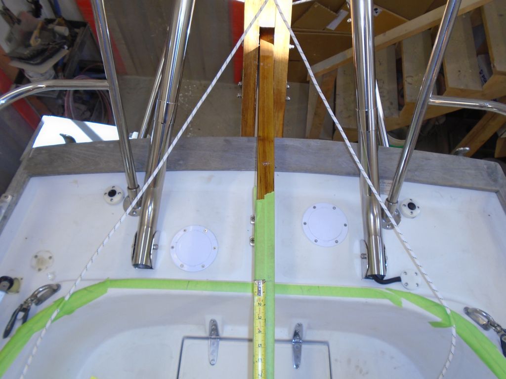
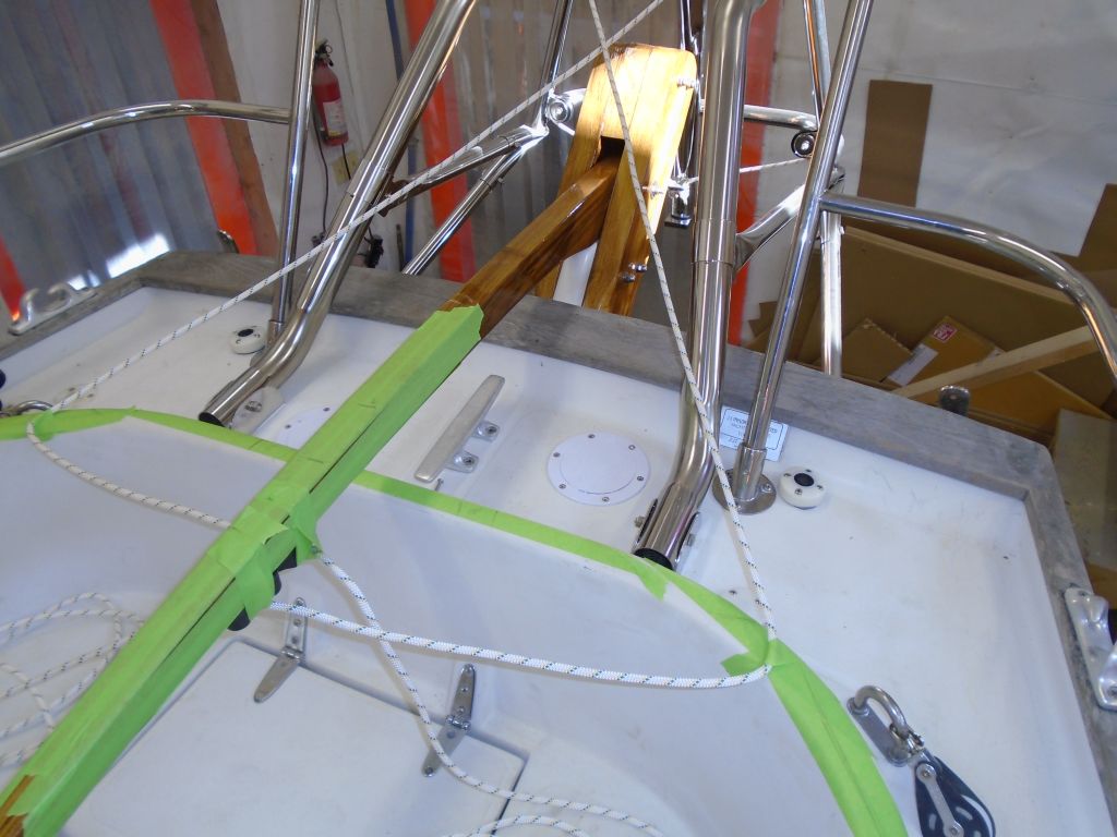
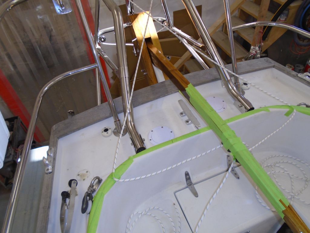
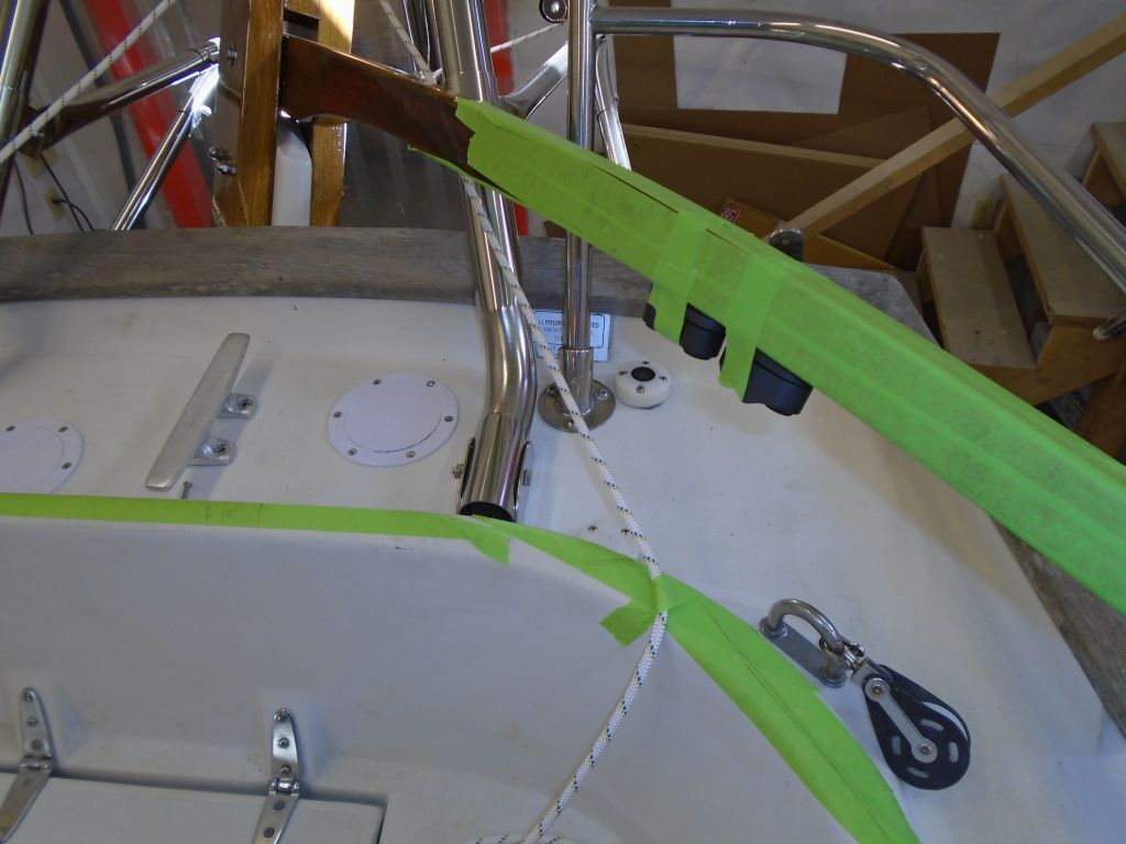
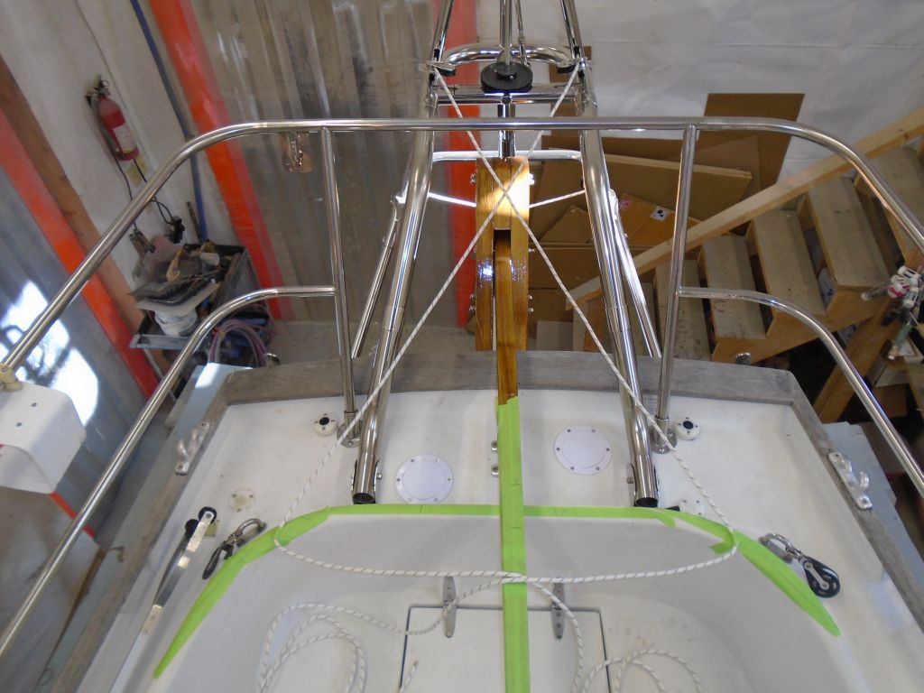
To determine what sort of hardware was required to run the pendulum lines from the Monitor windvane, I mocked up the two lines, using the supplied instructions as a guide. With tiller steering, the lines must cross when the leave the vane, so I led the lines to the opposite sides accordingly.
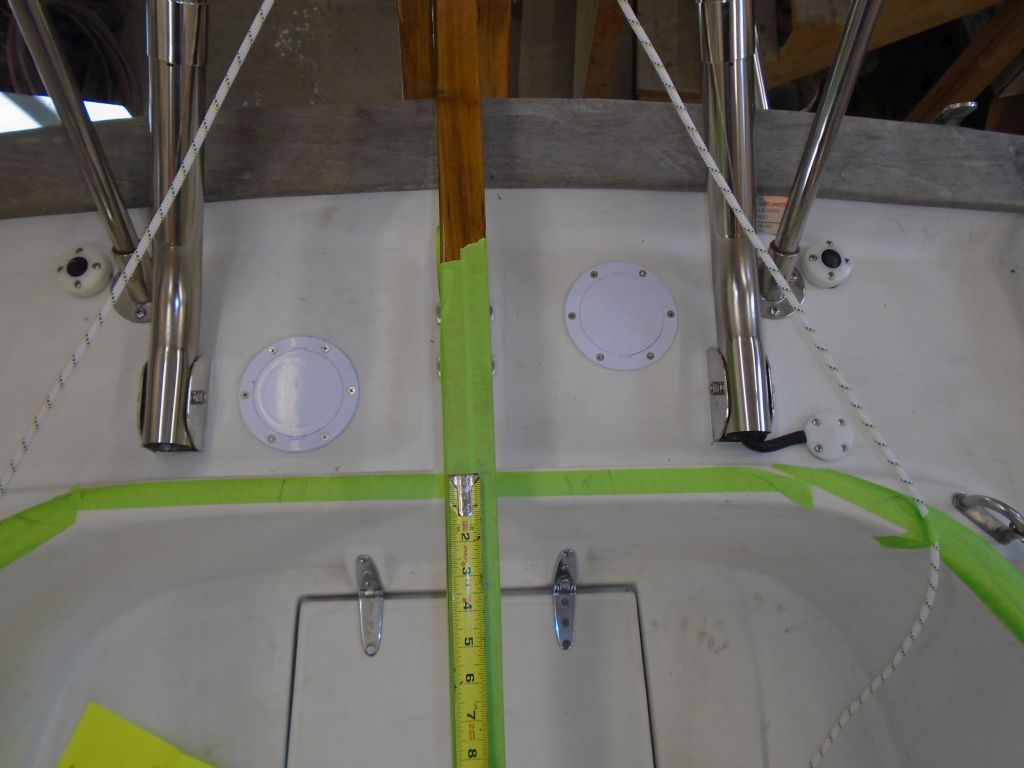
The guidance suggested that the lines should attach to the tiller approximately 30″ forward of the rudder post, so with protective masking tape covering the tiller (and the coaming surfaces, for marking purposes), I measured this distance, which ended up right over the aft coaming.
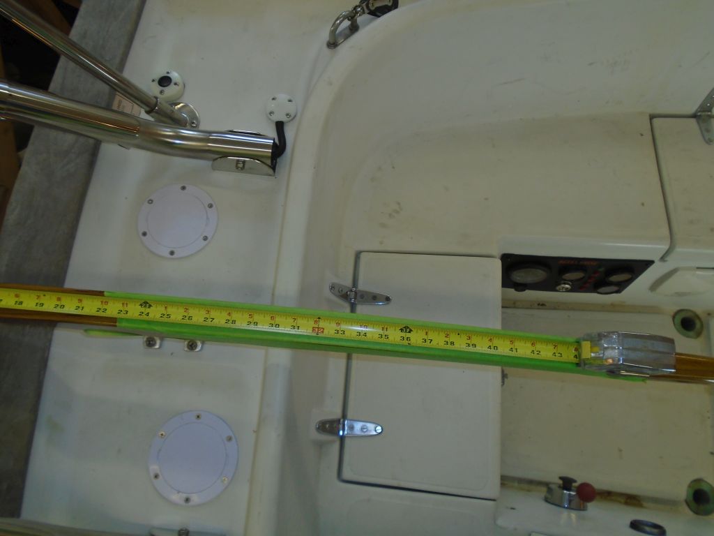
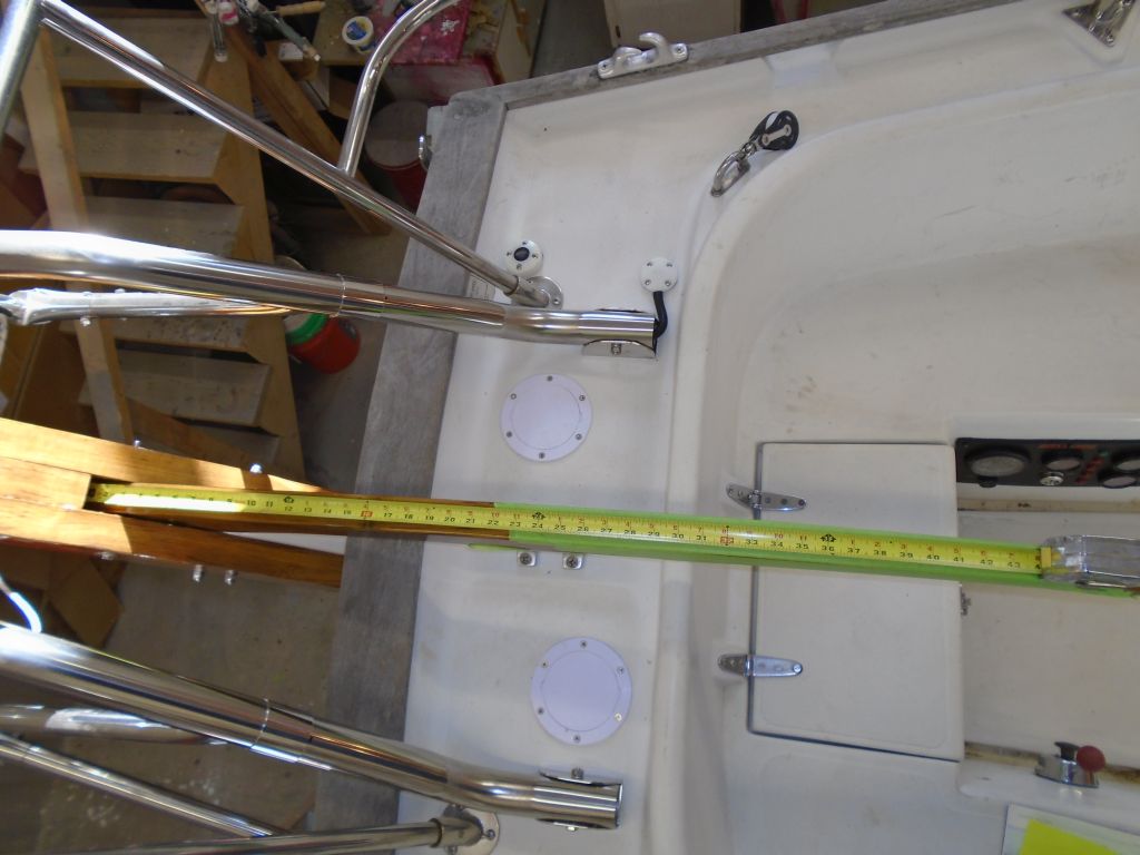
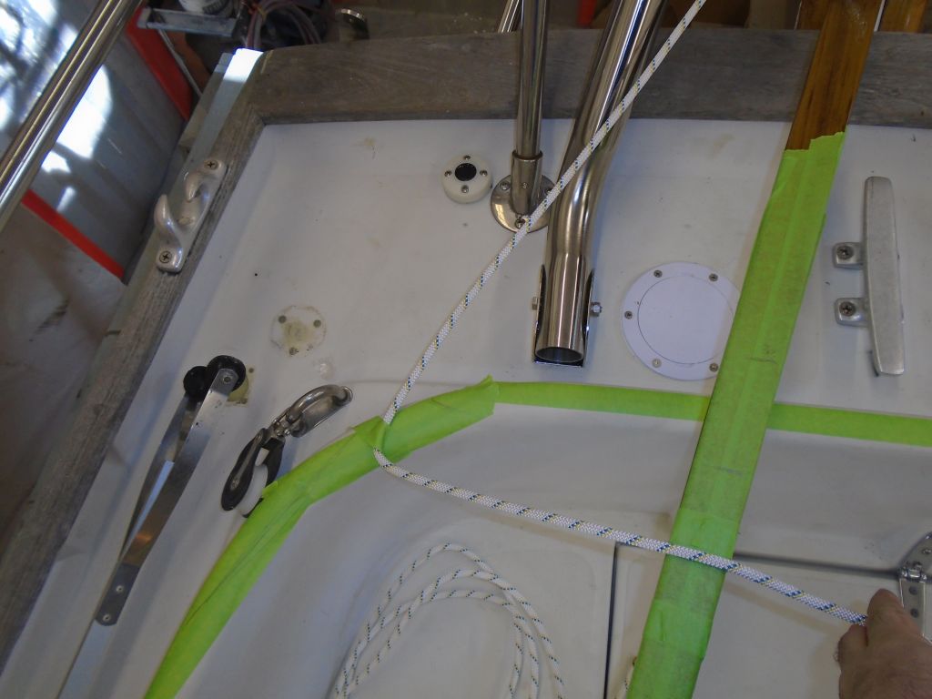
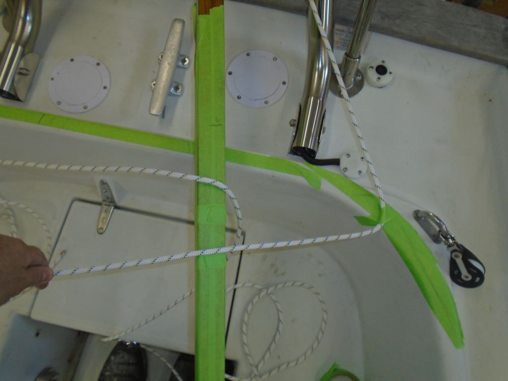
The instructions suggested that the control line should lead at right angles to the tiller when the tiller was turned 15° to the side, so I made marks on the coaming when the tiller was at this angle, and used a square to roughly locate the turning blocks’ locations on the coamings. The design of the coamings, and the way the lines led forward from the vane, limited the realistic options for block placement, so I adjusted the proposed tiller mounting location forward as needed (about 3″ or more forward of the 30″ mark) in order to achieve close to the desired 90° angle for the control line from the tiller to the coaming block.
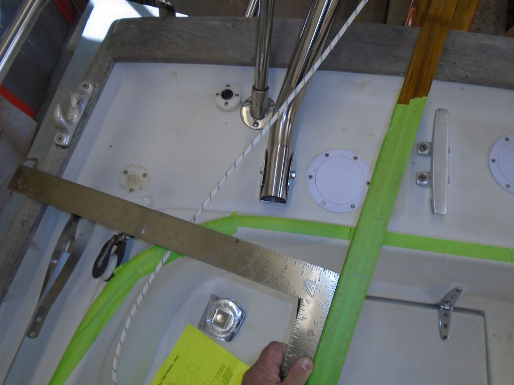
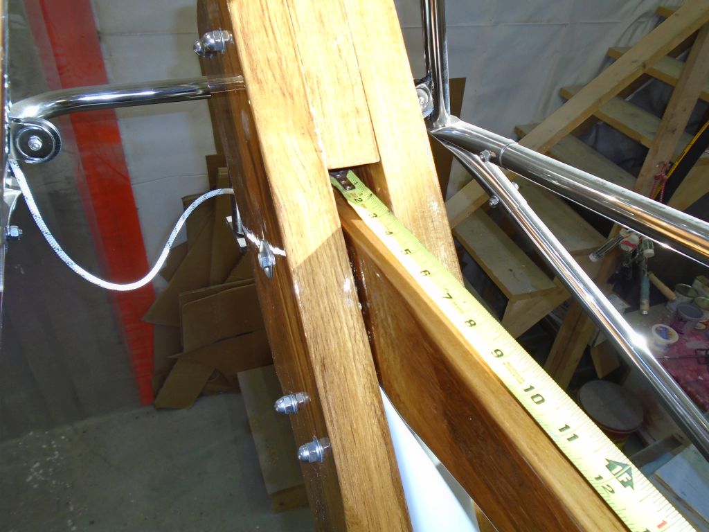
The tiller attachment kit included two cam cleats to mount on the underside of the tiller. With the design of the tiller, and how it related to the coamings as it turned, this was a second reason the attachment point needed to move forward, as the cleats would interfere with the coaming if mounted any further aft.

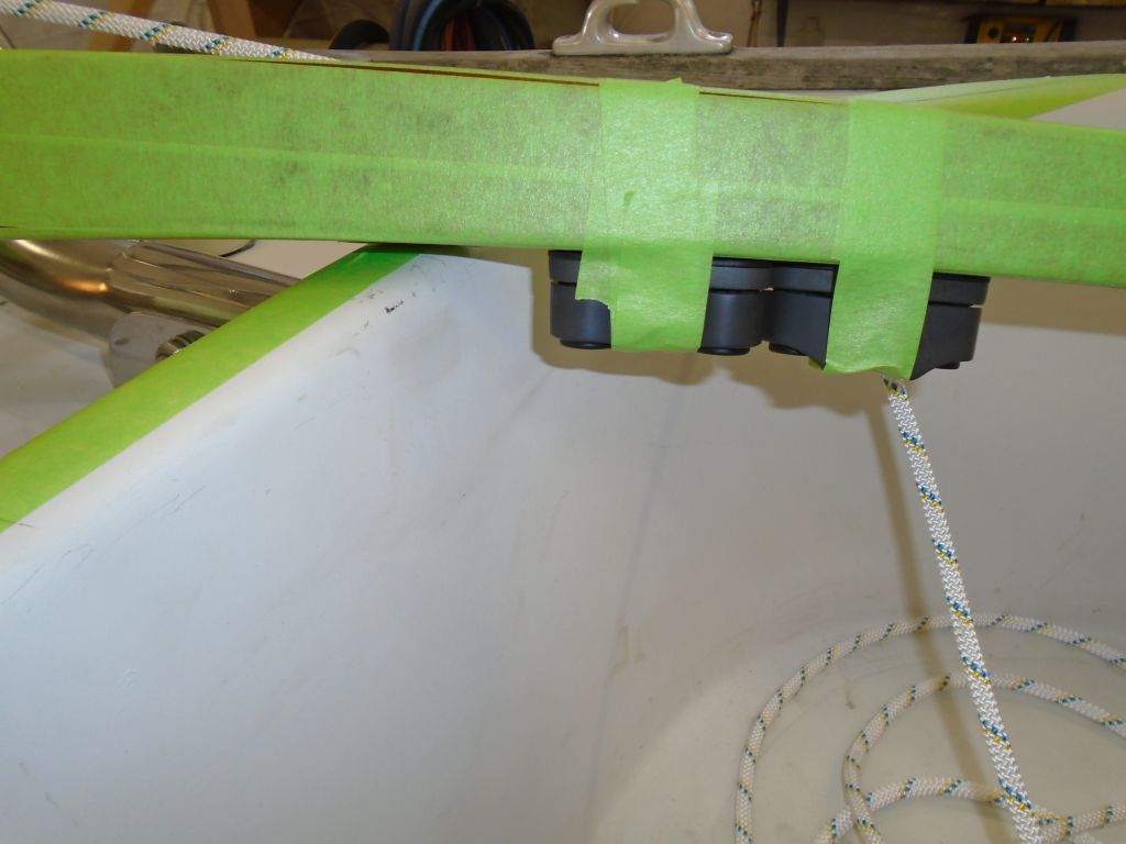
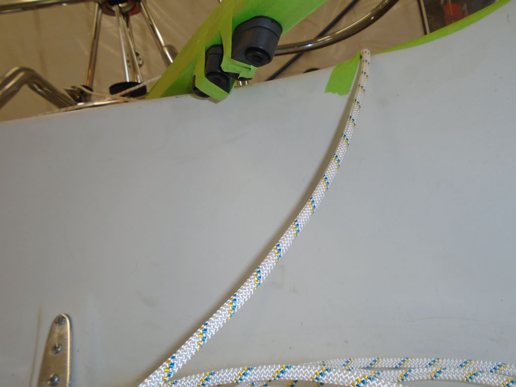
Of course the tiller could be lifted for additional clearance beyond this point, but mounting the cleats any further aft would likely interfere with normal use of the tiller both on and off the windvane.
In the end, this arrangement looked like it should work well, and at least allowed me to order a pair of cheek blocks to mount on the coamings. The proposed leads were straight and fair, and with the minor adjustments to the ideals suggested by the manual, fulfilled all basic requirements. I took the time to check with Scanmar, manufacturer of the windvane, about any repercussions from locating the tiller attachment further forward, and the answer was that this increased leverage on the tiller–not a bad thing–and there didn’t seem to be any negatives given the overall installation situation. The reality was that there wasn’t much for other options anyway, but it was good to know that the minor adjustments required wouldn’t negatively impact the performance.
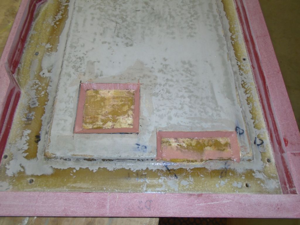
After an appointment away from the shop during the mid-morning, I got back to things with the engine hatch. The clearance above two sections of the engine–the secondary fuel filter and part of the cooling system–was tight enough that I decided to omit the hatch coring in those two areas. I hoped that final alignment adjustments on the engine would actually lower the front of the engine, increasing this clearance, but I couldn’t be sure, and if I had to raise the engine at all, clearance could become an issue. So after marking the rough perimeters of the areas in question, down on the bench I cut out the coring from these areas, then sealed the exposed core and created fillets with thickened epoxy around the edges of the cutouts.
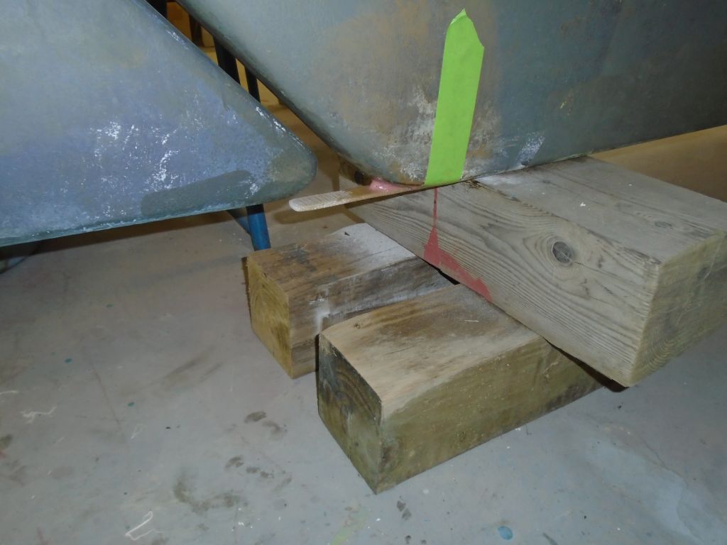
While I had the epoxy going, I quickly prepared the bottom edge of the aft side if the keel and installed a slim fiberglass batten to extend aft beyond the slot formed by the rudder and keel. This batten would help any lines that one might run over to slip aft cleanly, and reduce or minimize the chance that they might get hooked in that open slot before the rudder. I taped the batten in place while the epoxy cured.
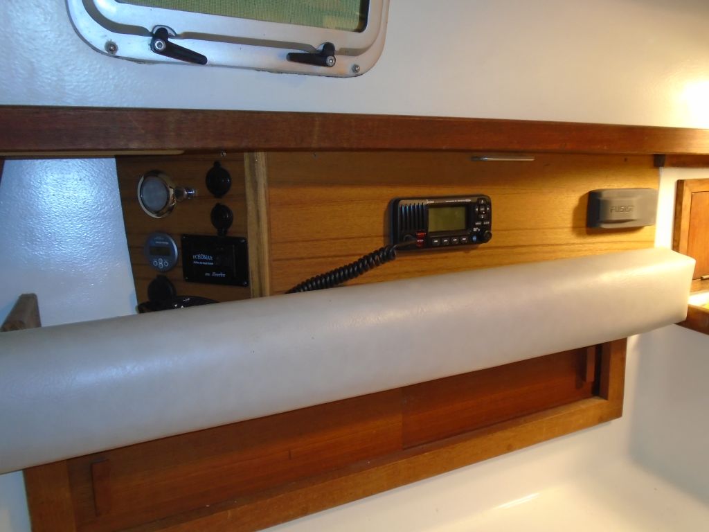
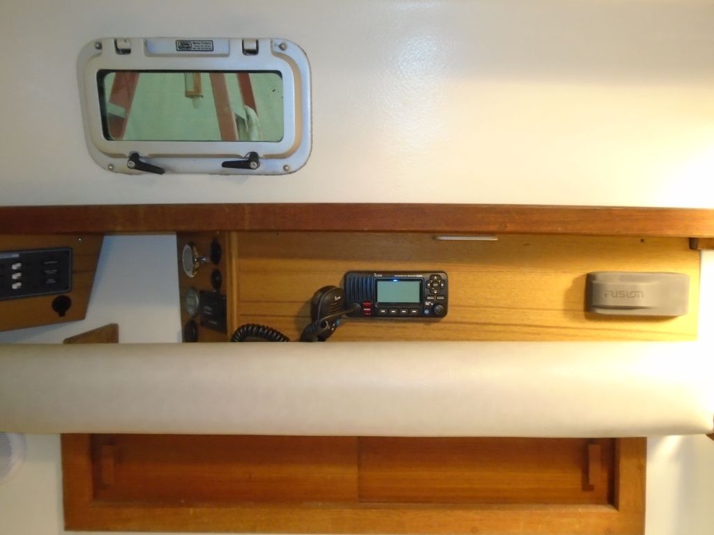
With the owner’s new VHF radio now on hand, I could move forward with the final installation on the new electronics locker panel, along with the recently-arrived stereo control unit. With minor adjustments that the owner and I had discussed previously, I laid out the cutouts for these two components according to the diagram and mockup I’d worked out a couple weeks prior, then installed the two units to the panel.

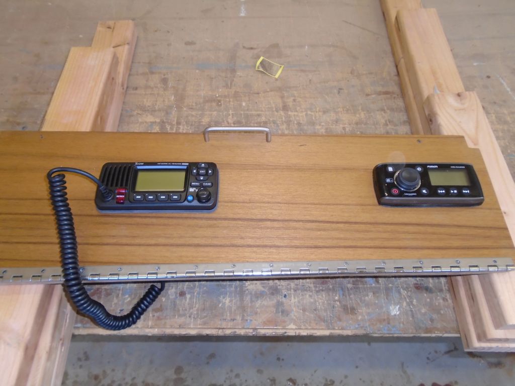
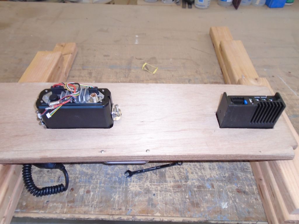
With the hinged panel resecured in the boat, I made up the final wiring connections. I didn’t have an antenna connector on hand for the VHF, so I’d finish that up once I got the new parts required. Both units had various extra wires that I tied up as well as I could; for the stereo speaker wiring, I installed removable connectors so the whole panel could be removed for storage during the off-season. I sent the owner some options for mounting the VHF microphone.

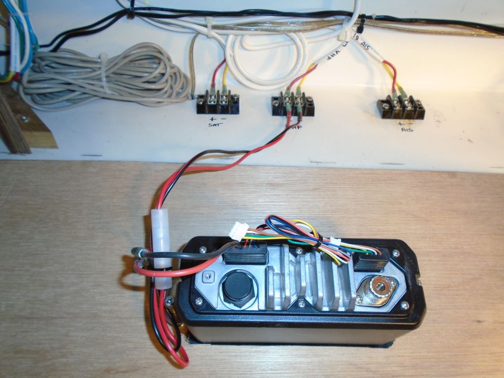
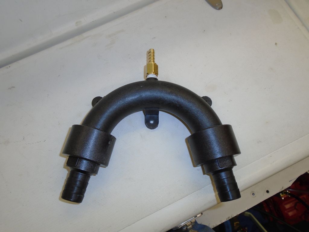
I was all set to finish up the plumbing for the engine’s raw water siphon break, which I planned to mount in the cockpit locker. I removed the supplied valve fitting from the top of the siphon and installed a hose nipple that I could hook into the existing overflow hose that connected with the exhaust gooseneck at the transom, and prepared a hole to communicate between the engine room and cockpit locker for the hose runs. To my dismay, however, I discovered that the connection on the engine was for a larger hose than I’d thought–1″ versus 3/4″–and the offcuts of 1″ hose that I had on hand weren’t long enough to make the journey required, so I had to halt the project and order enough 1″ hose to do the job. It seemed to me that these connections were different every time I installed one of these engines–I was sure I’d used 3/4″ hose before, but perhaps my memory was just short. In any event, final installation, with all the basic preparations made, would be quick once I got the new hose.
Total time billed on this job today: 6.25 hours
0600 Weather Observation:
25°, clear. Forecast for the day: sunny, around 50