

March 29, 2016
Salty 29
Tuesday
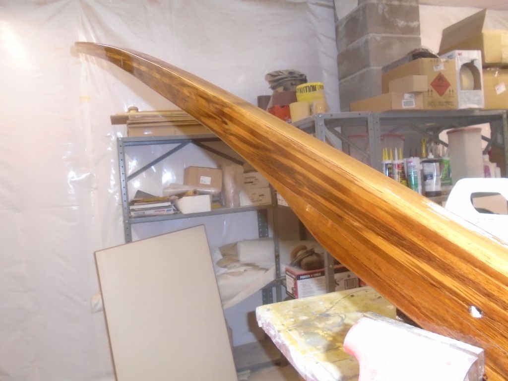
Not wanting to let the varnish work fall too far behind, I sanded and varnished (5) the tiller once again.
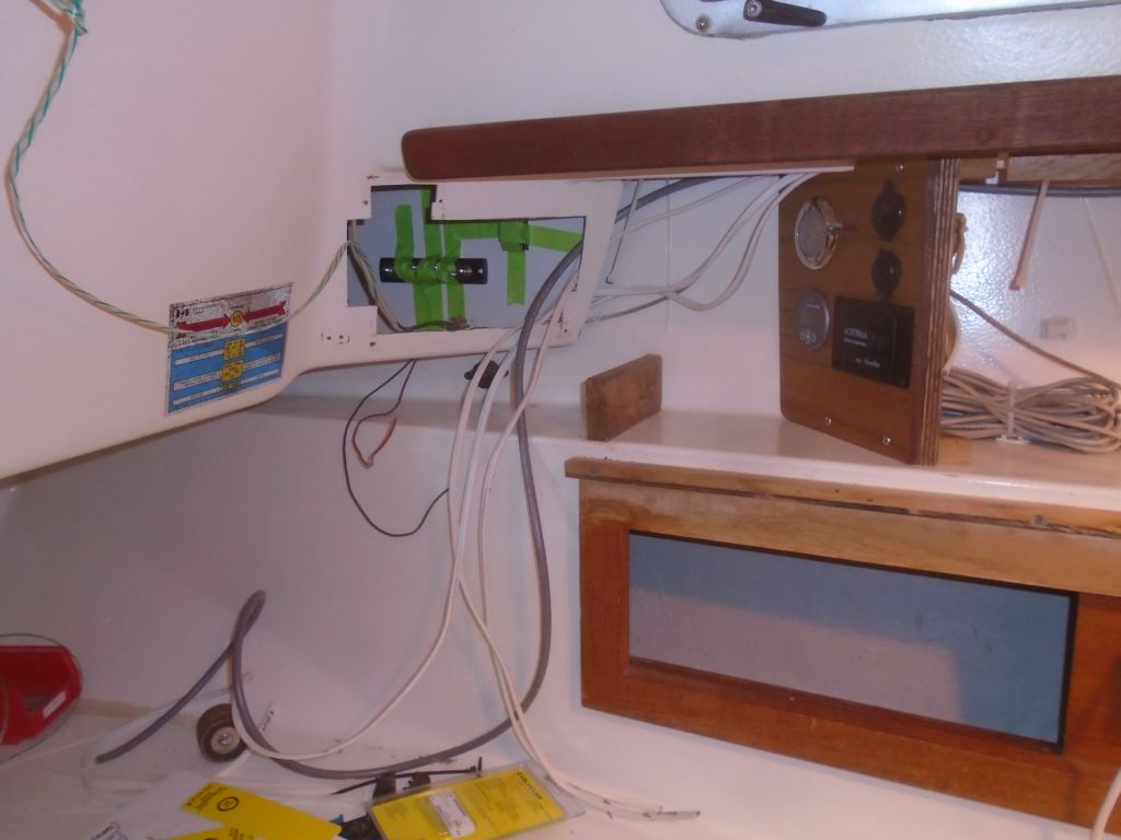
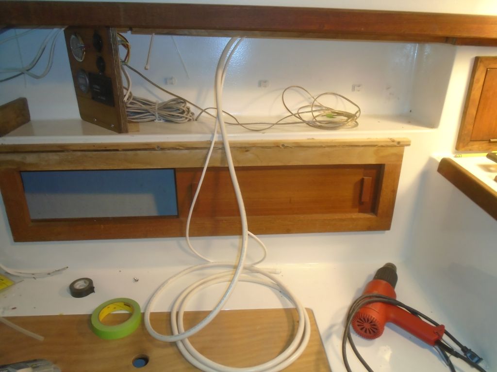
I wanted to minimize running wires back and forth across the aft end of the boat, but I couldn’t avoid it entirely. The red LED light in the electronics locker would best be tied in to the cabin lights circuit, and operated separately on its own switch nearby. I didn’t have a switch on hand, so I ordered one, and then I pre-wired (to the extent possible, other than connecting to the new switch) the back of the light fixture and, using the messenger lines I’d run in when I removed the old wiring, pulled the wire across through the after wire chases so it could connect with the cabin lights circuit on the starboard panel. At the same time, I pulled through a length of speaker wire to service the starboard speaker now or in the future, and pulled through a new length of messenger so I could run additional wires as needed.
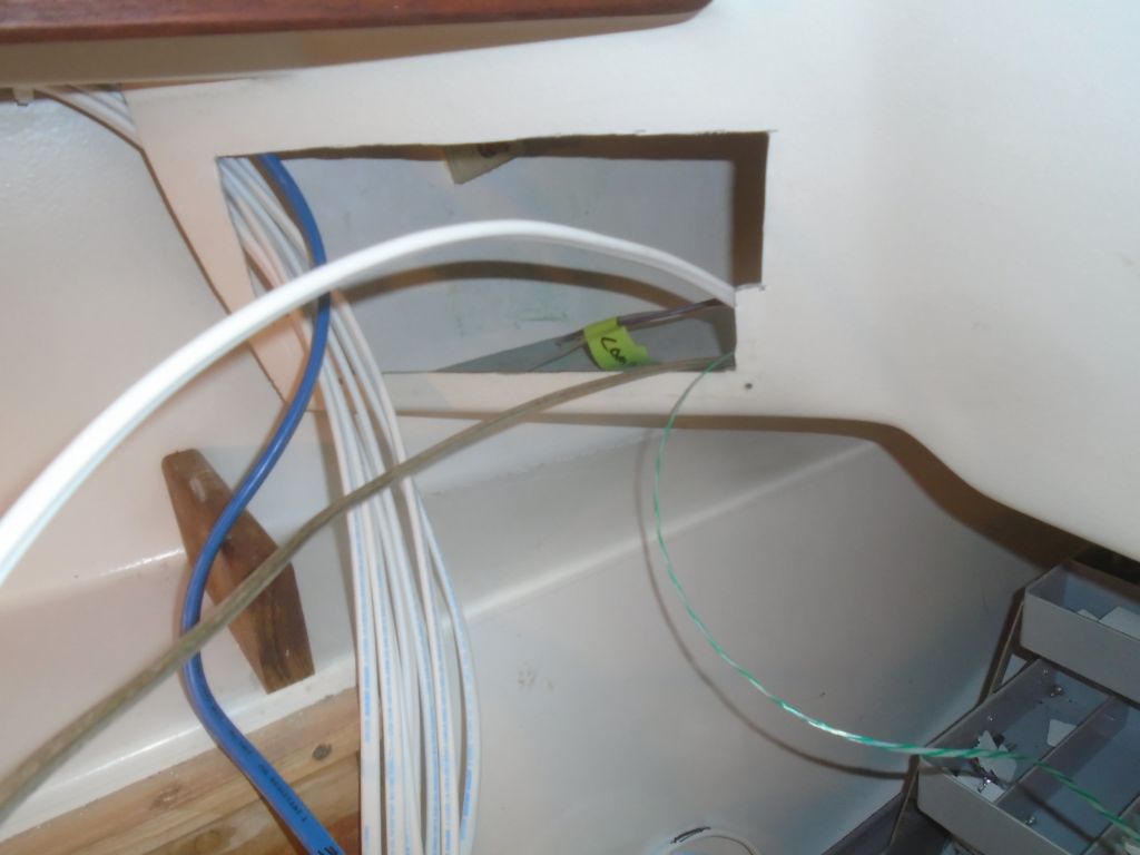
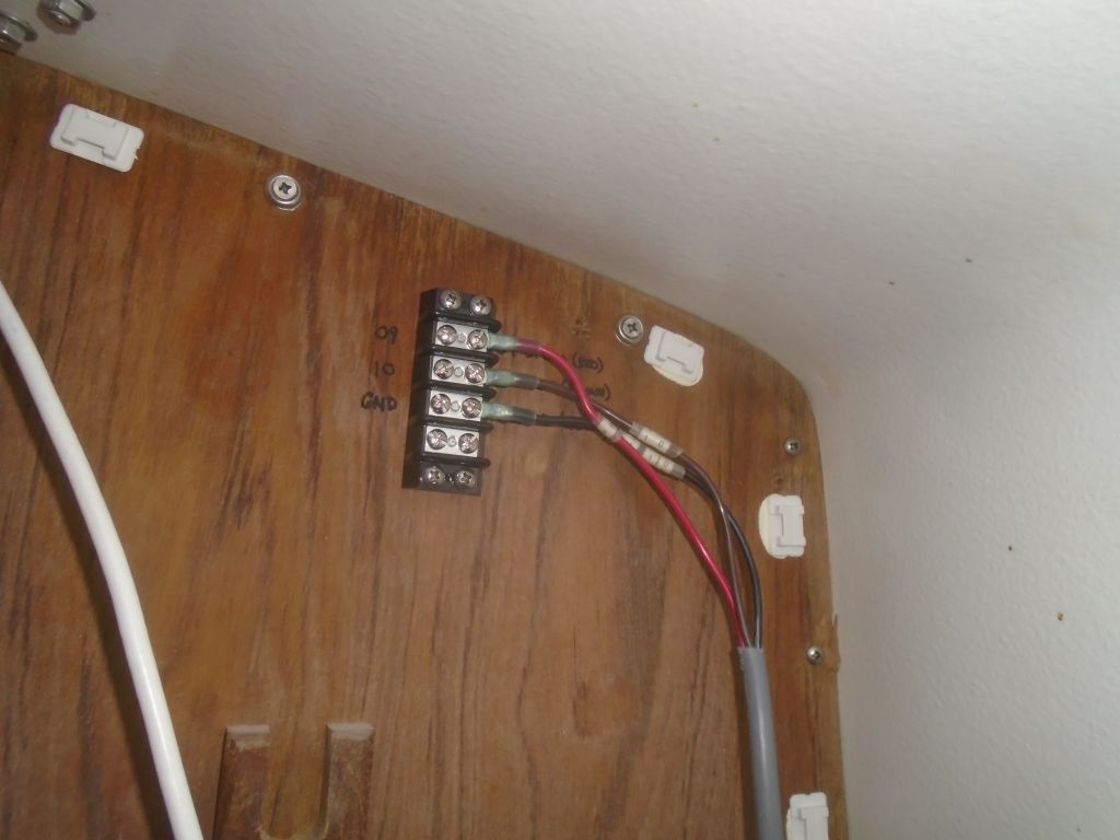
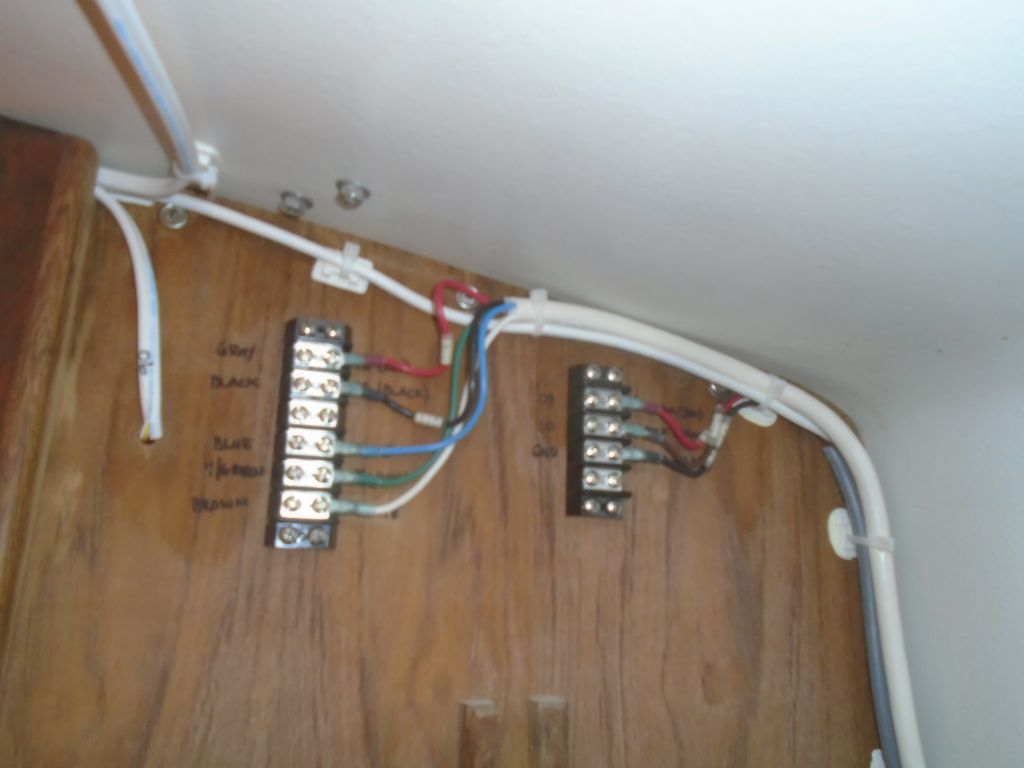
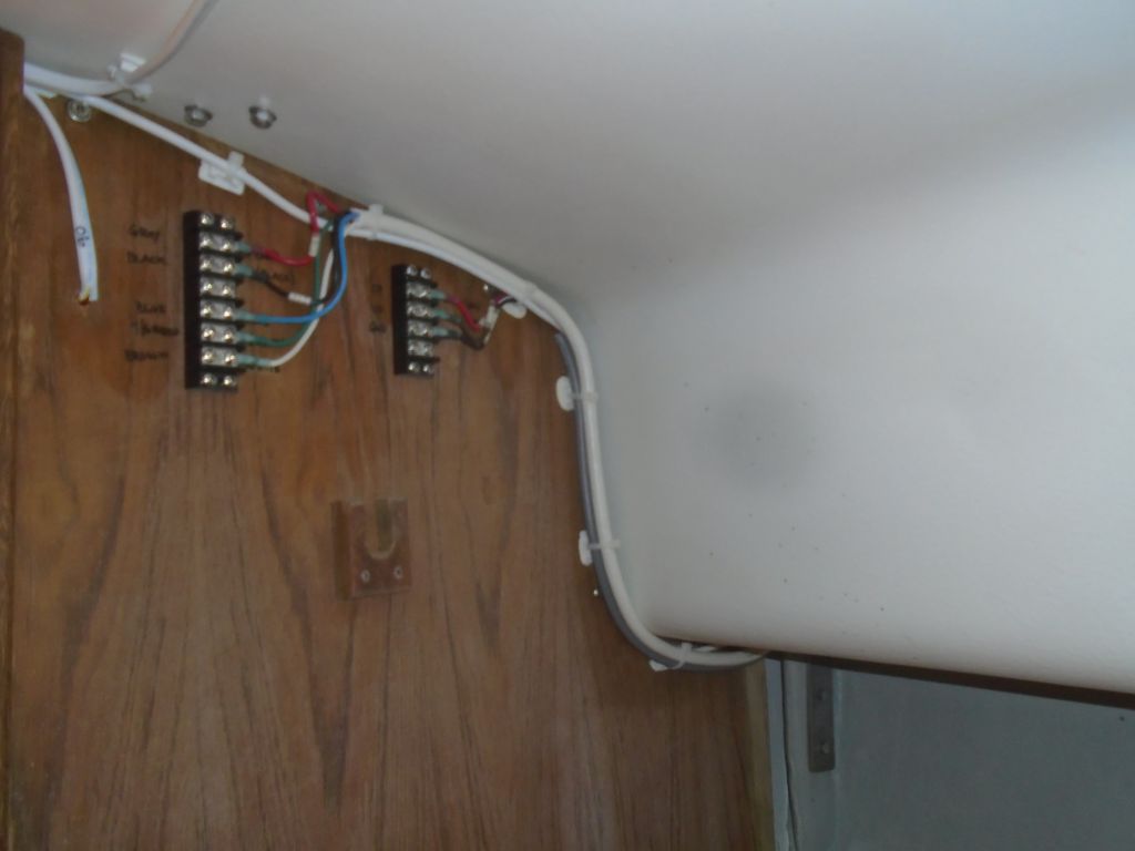
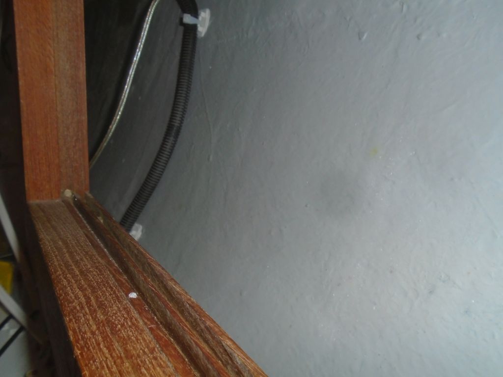
Mast wiring requirements on this boat included a VHF antenna cable, as well as three wires for the combination steaming/deck light (two leads plus a negative), and five wires for the masthead unit containing the radar target enhancer and all-round white LED light. The wires from the mast would need a point of easy connection in order to allow for unstepping the mast. To keep the wire runs easy and clean, I used multi-conductor cable for each. I’d had to order a length of 5-conductor cable for the RTE, so I started now with the 3 wire cable for the mast light, leading the wire forward into the hanging locker on the port side, where I installed a terminal block for the wire connection. I labeled each wire accordingly, and left the panel end to run long for now while it awaited final termination there.
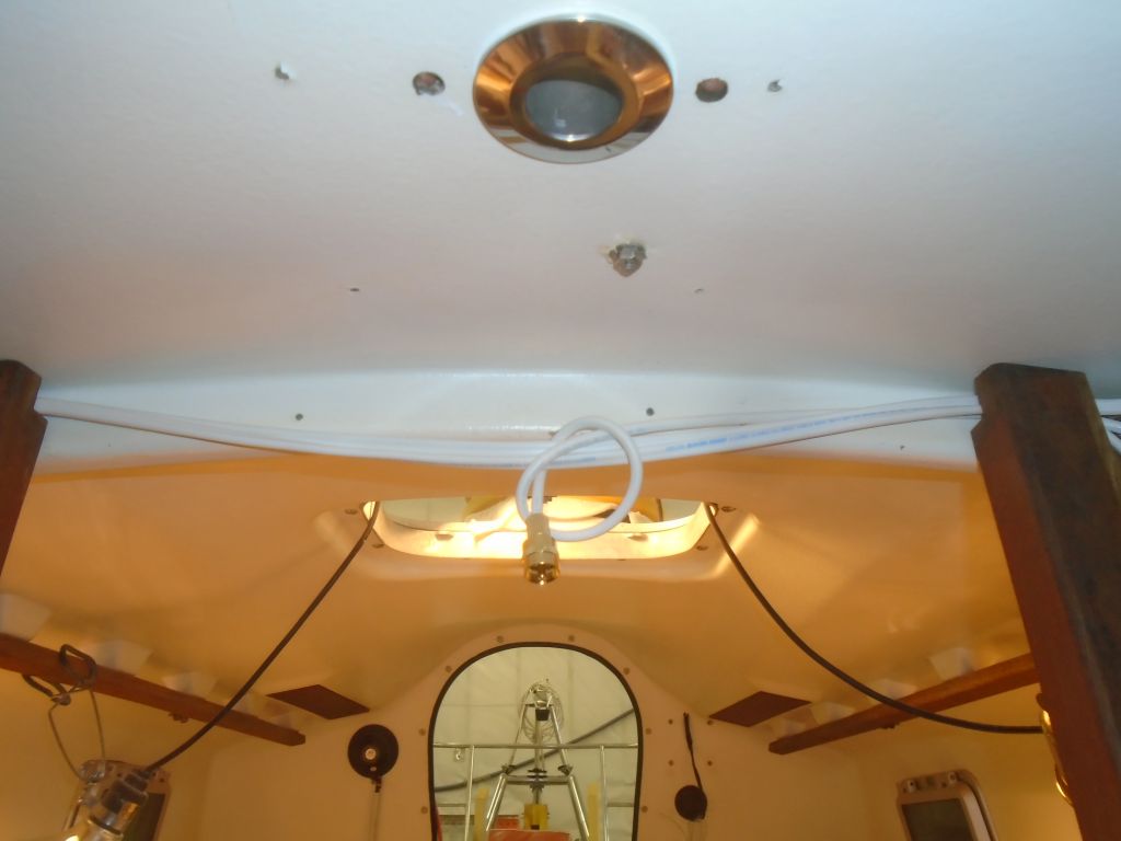
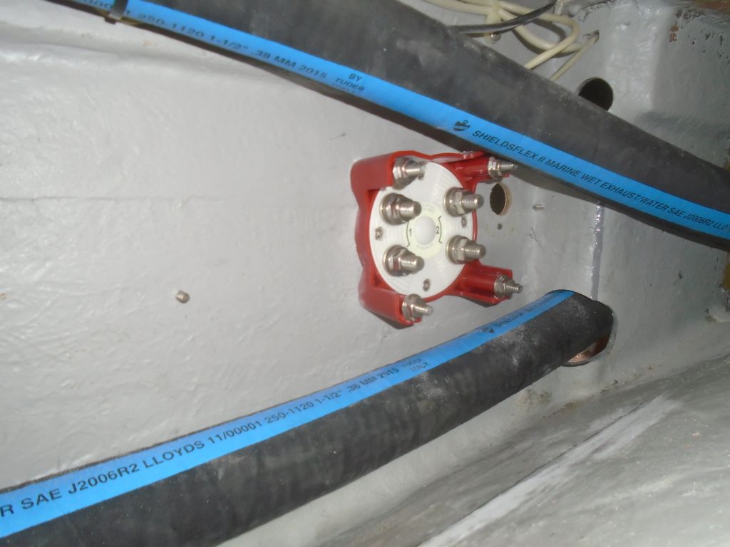
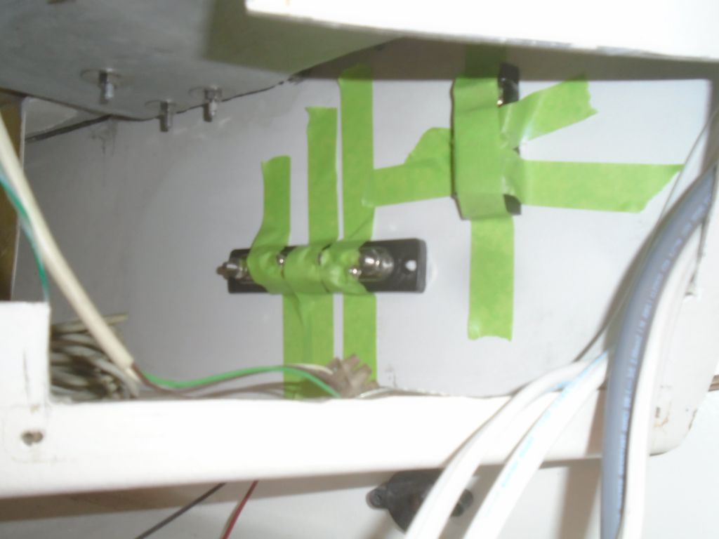
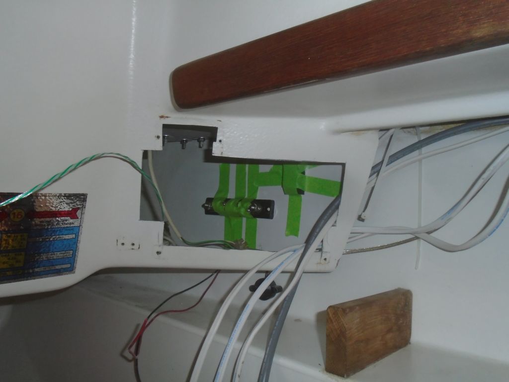
Next, I ran in a length of VHF cable, leaving the after end a bit long and unterminated for now, but because the connector from the mast end would be too large to pass through the smallish opening in the beam to reach the wiring area, I made up the connection end near the new mast wiring deck fitting, where it would be hidden inside the small cover box on the overhead.
Later, with the new 5-conductor cable on hand, I installed a second terminal block for the RTE and anchor light, and made up the five wires there before securing the mast wiring runs along the bulkhead and pulling aft all the excess wire from the various runs, leaving the aft ends unterminated for the moment. I labeled all the new wires and the terminal block as needed to ensure proper connections when the mast was stepped, now and in the future.

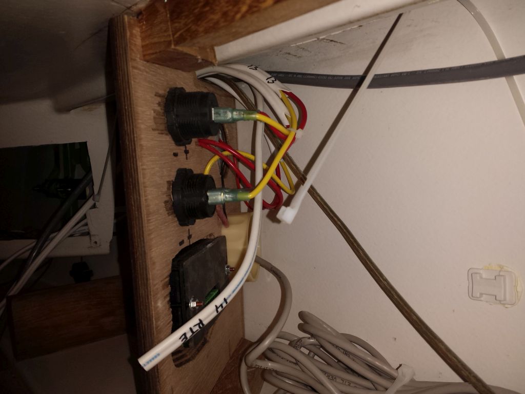
To the two power outlets in the angled panel, I led two short wire pairs, and made up the ends at the outlets’ terminals. With other wiring going on nearby, it’d be a little bit till I could do the final cleanup and securing of the wiring in this area.
The question of where to install the various components of the battery system–distribution busses, the Automatic Charging Relay (ACR), and the shunt for the battery monitor, had been on my mind for a while. These connections needed to be readily accessible for installation, but also well-protected and out of sight. The challenges involved in running in the various lengths of larger battery cable also dictated (or eliminated) various possibilities, particularly with an eye towards minimizing cable runs, and I considered the various possibilities for how to lead the cables to and from the new house battery compartment and wherever the start battery would end up (hopefully the forward end of the engine room), and at this writing there were a few possibilities in play that could work, which was all I really needed to know at the moment. When the time came soon to actually run the cables, I’d figure out which option worked the best for me, and for the future.
The engine room didn’t really have the space (not once the engine and its ancillary installations were complete, and in any event wasn’t the best location for most of this anyway. There wasn’t room in the battery locker itself. Eventually, I decided to build a small wooden platform–which would be the surface to which I’d actually install the distribution busses and other items–that would fit in the port settee locker against the hull. This would give the access required for maintenance and installation, and with the components well-covered would protect the wiring within, without impinging too much on available storage space. This particular locker already contained a bilge pump and related hoses, plus the depthsounder transducer. As a bonus, it was also convenient to lead in the Ethernet cable for the battery monitor, which was located directly above (well, semi-directly), and since the batteries were also on the port side, wiring would be as efficient as possible.
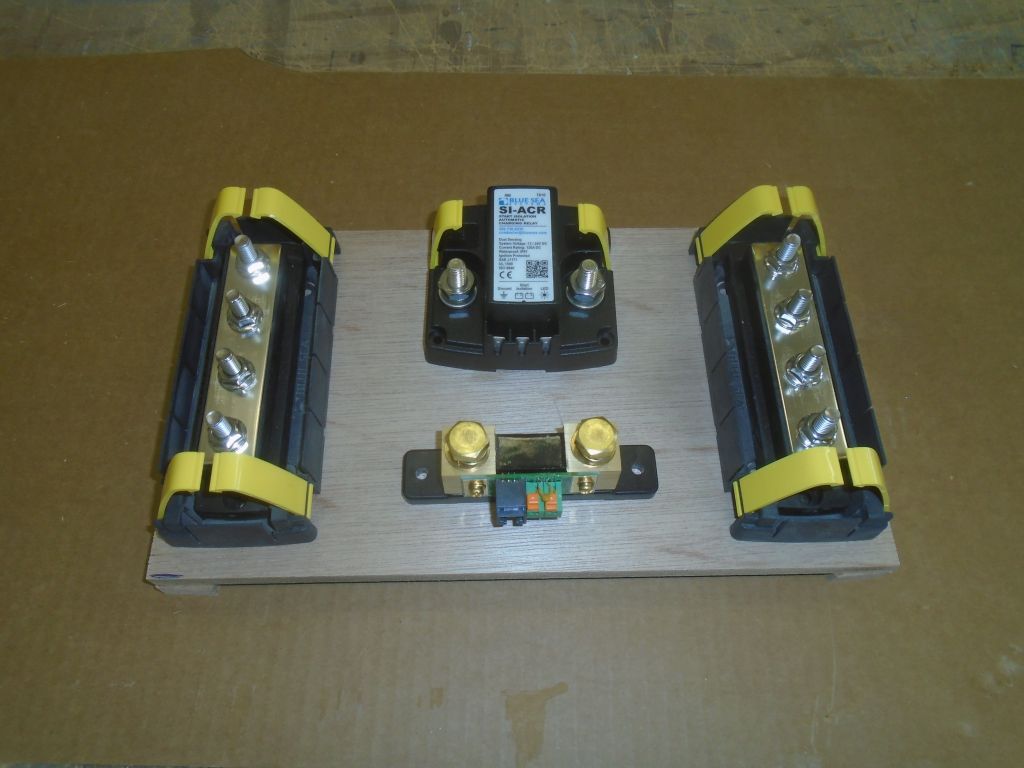
To this end, I laid out a plywood panel to contain the positive and negative distribution busses, the ACR, and the monitor shunt. I built plywood “legs” so the platform would only rest on the hull in specific areas, and, after a test-fit, I epoxy-coated the whole platform in advance, leaving it to cure. In the locker, I prepared the eventual bonding surface by sanding the factory locker gelcoat where the legs would rest.

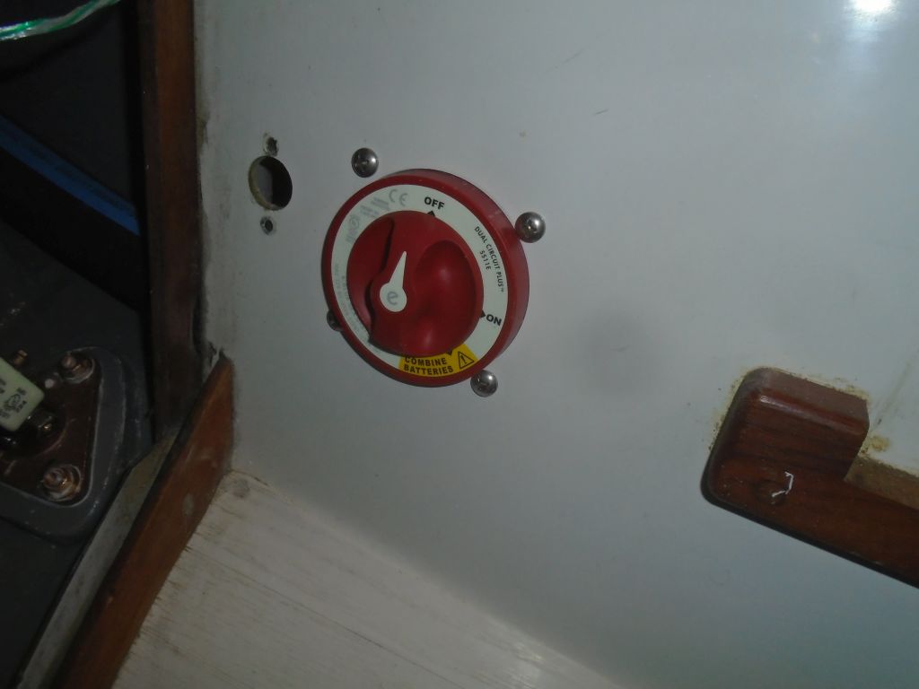
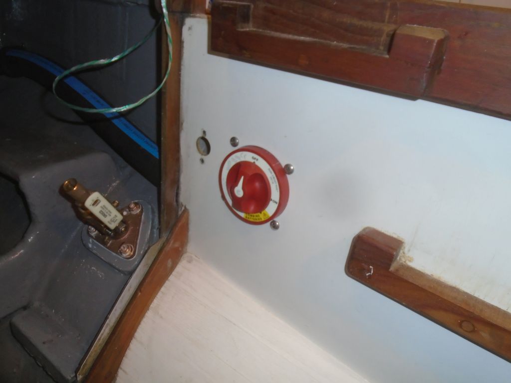
It made sense to install the new battery switch on this side as well; the old switch had been to starboard. I mounted the new switch from the back side of the locker side, beneath the companionway steps.
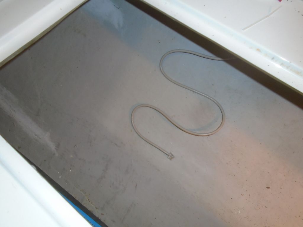
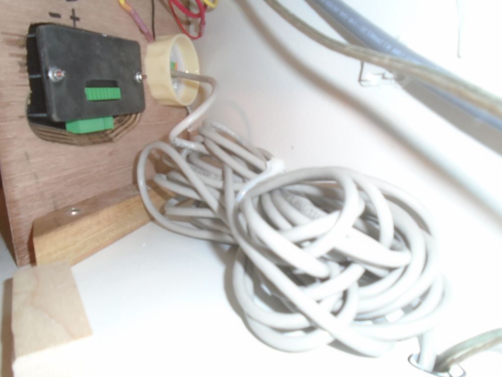
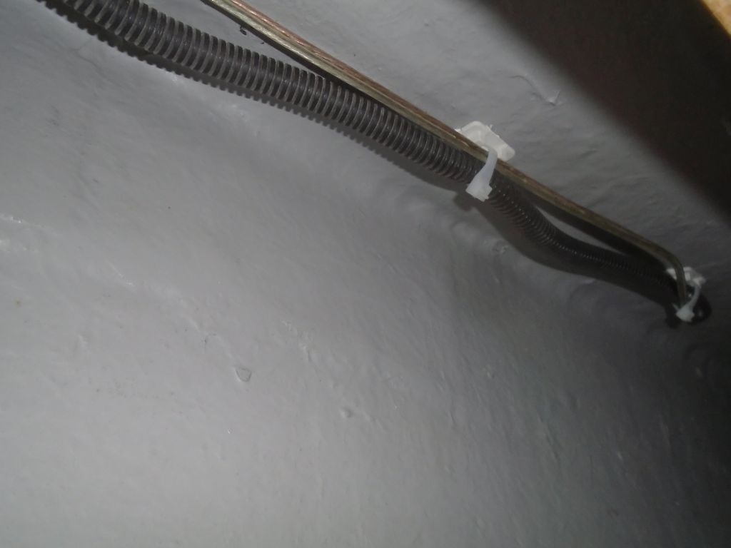
Now I could run in the Ethernet cable for the battery monitor–the only direct connection between the display and the other wiring. There was room to run it hidden through the settee bottom and into the locker behind, then up into the new electronics locker above, where I tied up all the excess cable (I decided it was best to have it here) and connected the cable to the monitor. Inside the locker, I protected the cable with split loom, and secured it out of the way as much as possible. I also led in, through the same opening from above, a length of speaker wire for the port speaker, which would eventually be installed just aft of the sliding locker doors on each side.
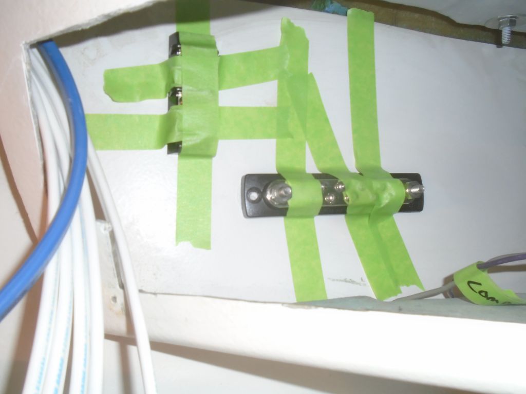
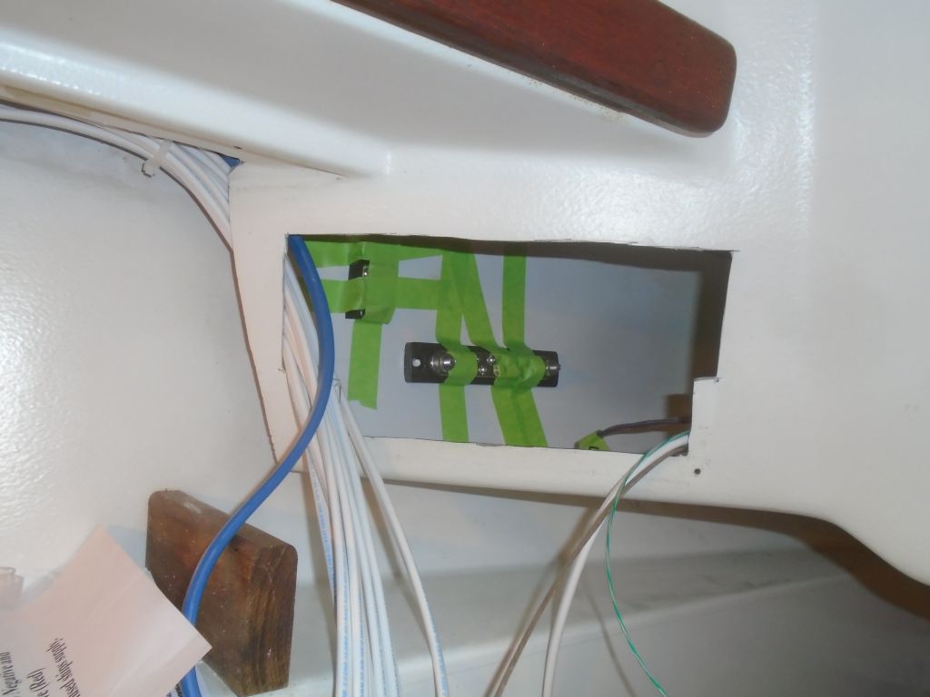
To prepare for the final wire termination in the two electrical panel locations, at the end of the day I used adhesive to install negative distribution busses and terminal blocks on each side, against the hull liner. I lightly sanded and solvent-washed these areas before securing the components with adhesive and tape to hold them while the adhesive cured. The terminal blocks would help minimize individual wire leads to the circuit breakers on the panel for some of the circuits containing multiple installations, such as cabin lights, electronics, and power outlets.
Total time billed on this job today: 7.25 hours
0600 Weather Observation:
Showers, 35°. Forecast for the day: clouds, showers, and eventual clearing; windy. HIgh in the 40s