

March 21, 2016
Salty 22
Monday
I started the day with another light sanding on the rudder cheeks and tiller, preparing them for their next coats of varnish. I’d intended to get back to this later, but it didn’t happen.
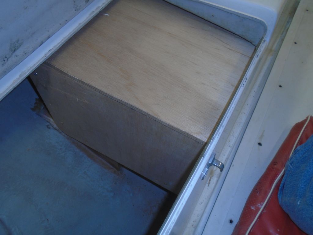
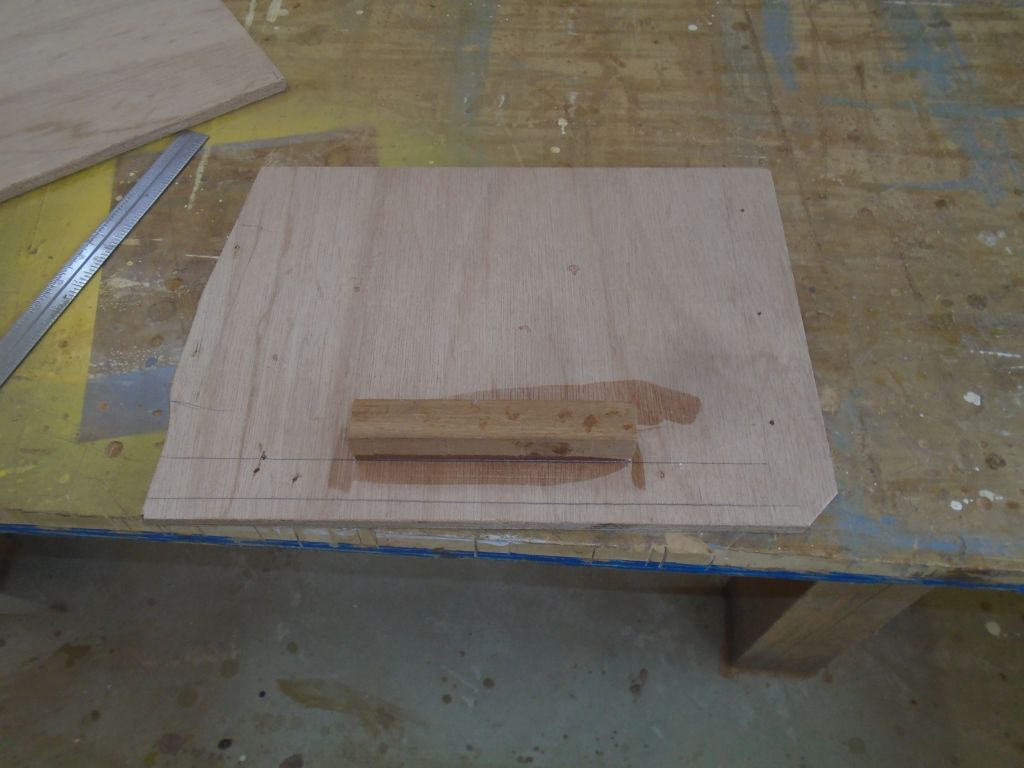
To finish up the main construction of the battery box in the cockpit locker, I had to build a top–a simple-enough proposition complicated by the fact that the locker and the box’s position within were not neat and square, and the height of the box meant that I couldn’t access the inner part of the lid for basic patterning and fitting. So I started with a narrow strip of cardboard so I could scribe the shape at the forward end, which was the most critical cut to make. I transferred this to a slightly oversized piece of plywood, and with the back side of the box removed, and a temporary cleat on the inboard edge of the locker to hold the top, I could finalize the shape of the top along the two locker edges–both of which required various contours and shaping–before marking the two straight cuts at the plywood edges of the box. It just took several rounds and ups and downs from the shop to eventually complete the new top.
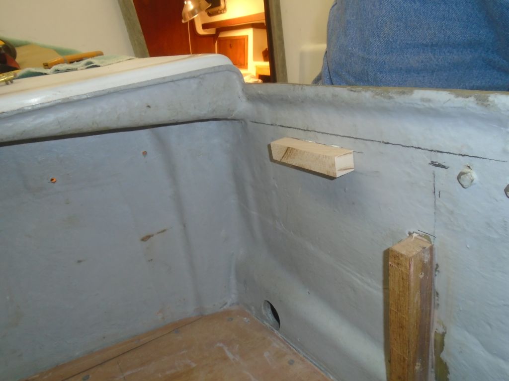

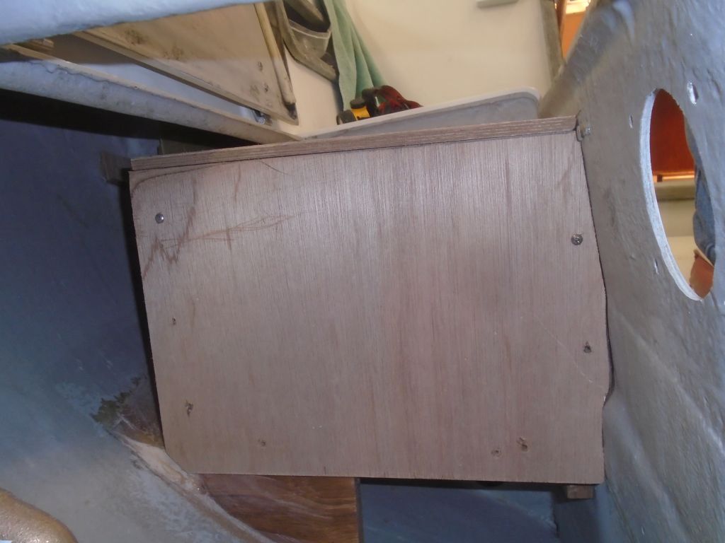
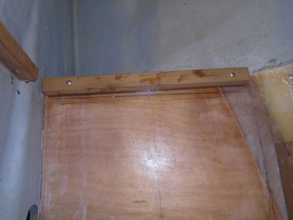
After making some reference marks inside the locker, and with the top in place, I prepared and installed with epoxy some hardwood cleats to support the top on the two locker edges, and a second pair of cleats slightly above, into which slots the top would slide. This would hold these two edges securely, and I’d install some sort of latch to complete the security of the top.

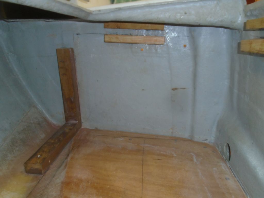
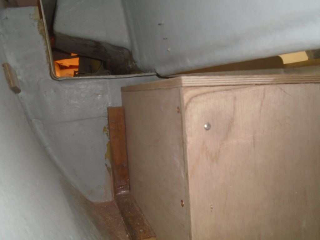
Meanwhile, I permanently secured the aft support cleat on the battery platform with epoxy, and added a little cleat to the inside of the back panel, just for ease of installation and alignment purposes. This cleat would rest on the shelf cleat and help the user install the back panel whenever it was necessary.
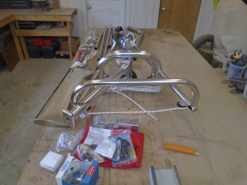
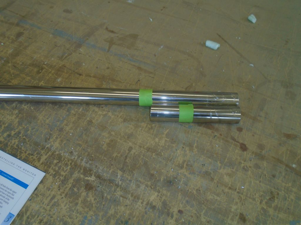
Next on my agenda was the new Monitor windvane, which installation I looked forward to, though I knew it’d likely present some challenges. When the unit arrived several weeks earlier, I’d taken the time to remove all the packing material–of which there was a huge trash bag full–so now I could more easily remove and lay out all the frame and support pieces on the bench for inspection.

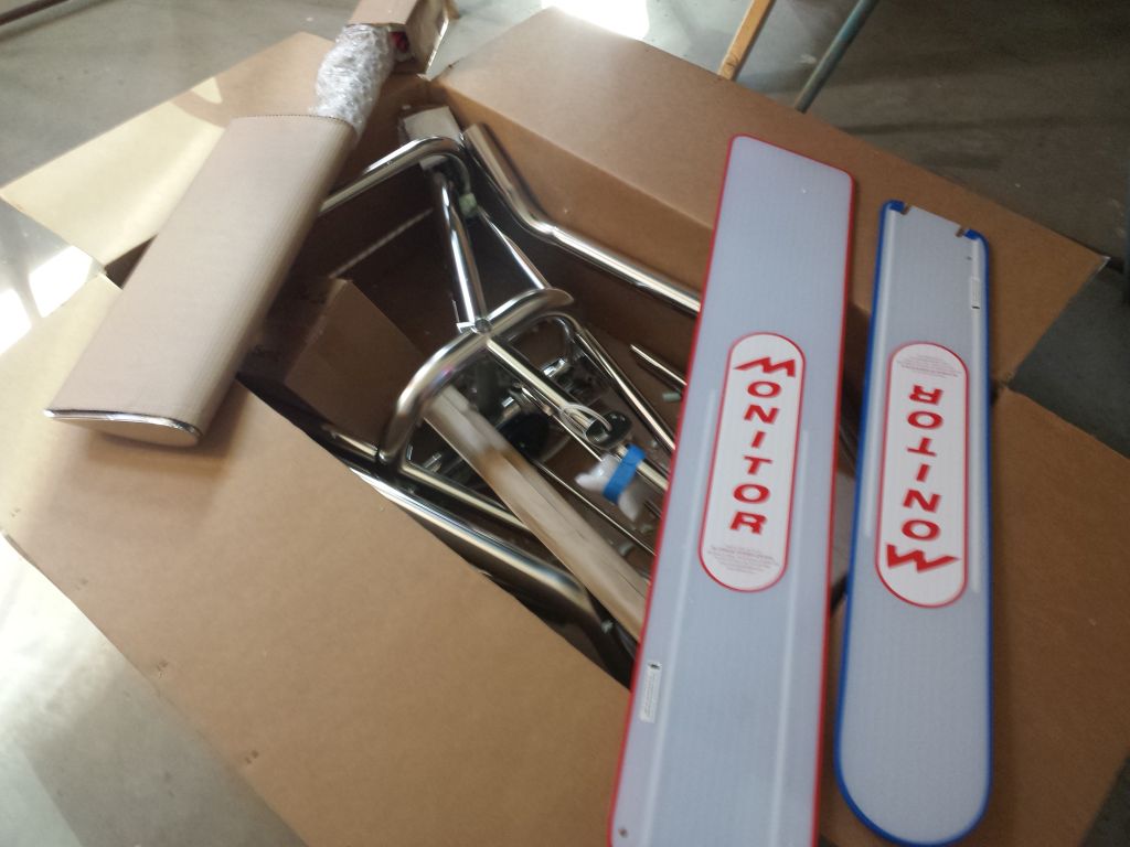

I’d already read through the extensive instruction manual once, but now I did so again, now with more attention to the specifics of this boat. I also reviewed the photos available of other Contessa 26 installations available on the Scanmar website.
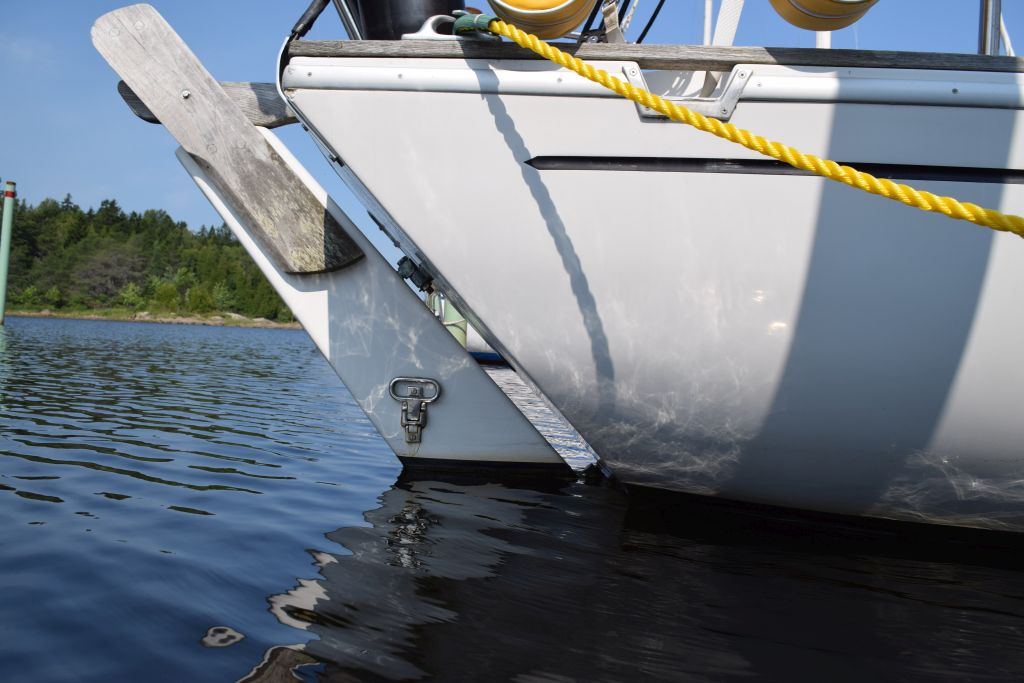
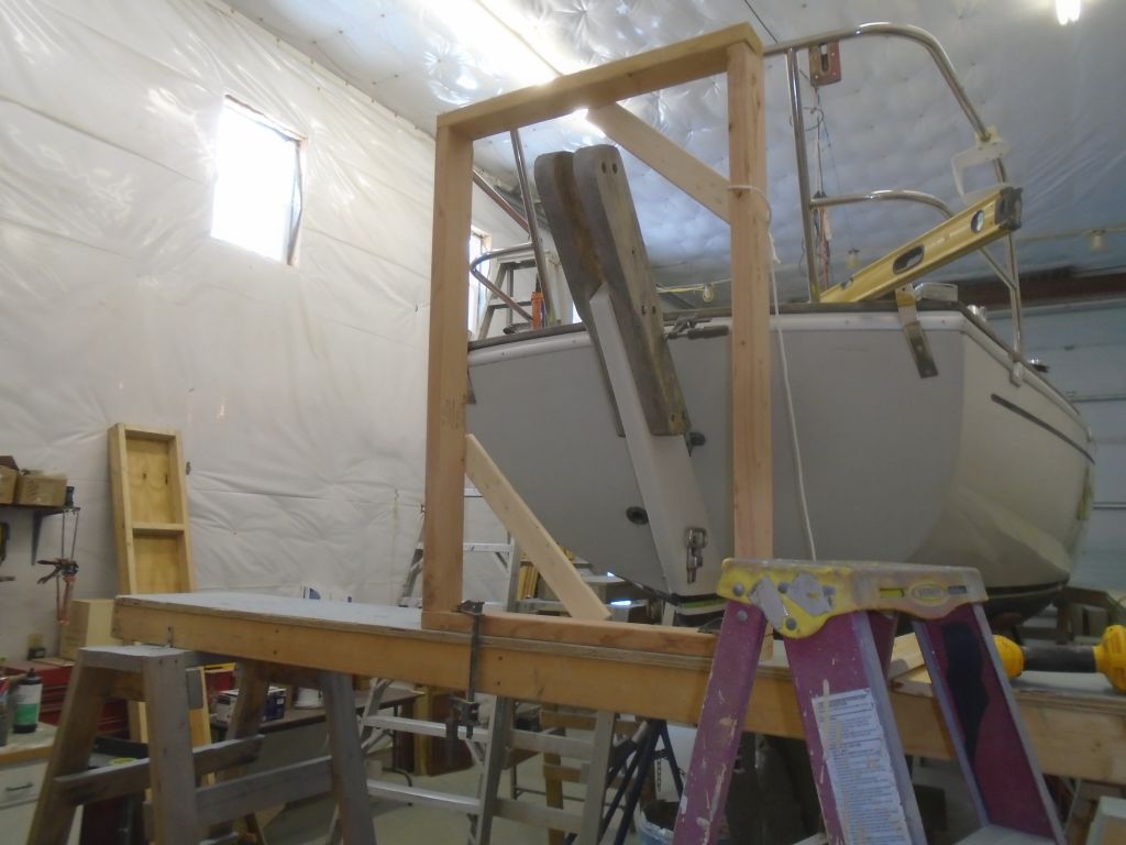
The first–and main–challenge was to somehow position the frame where it needed to be, suspended in mid-air. The manual suggested lines, but that wouldn’t work in this case because the frame would actually be mostly above deck level, and also had to be so far aft in order to clear the outboard rudder–which, with the strong transom rake and low topsides of this boat, probably made it one of the more challenging overall installations. All along, I’d been thinking that I wanted to build a wooden framework to support the windvane during the installation, and now I prepared to move forward with that idea.
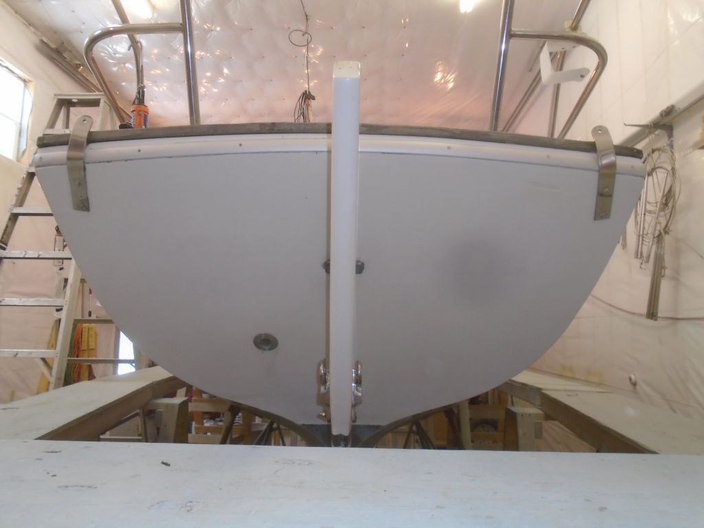
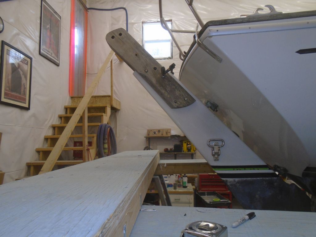
Before beginning the installation steps, I had two small details to deal with. First, I removed the old hailport from the transom, which the owner had requested, and to ensure that it wouldn’t end up beneath any of the frame pieces (it didn’t, but that’s neither here nor there). Then, to ensure proper clearance and positioning of the vane, I temporarily installed the old rudder cheeks just to give me the ultimate top/aft point of the rudder, which would ultimately be the defining point of the vane’s positioning. The rudder, and the space between the cheeks, would also be the ideal centerline for the vane.
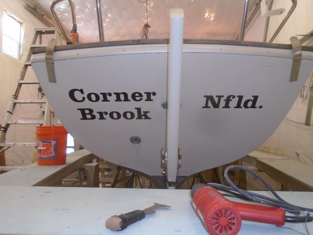
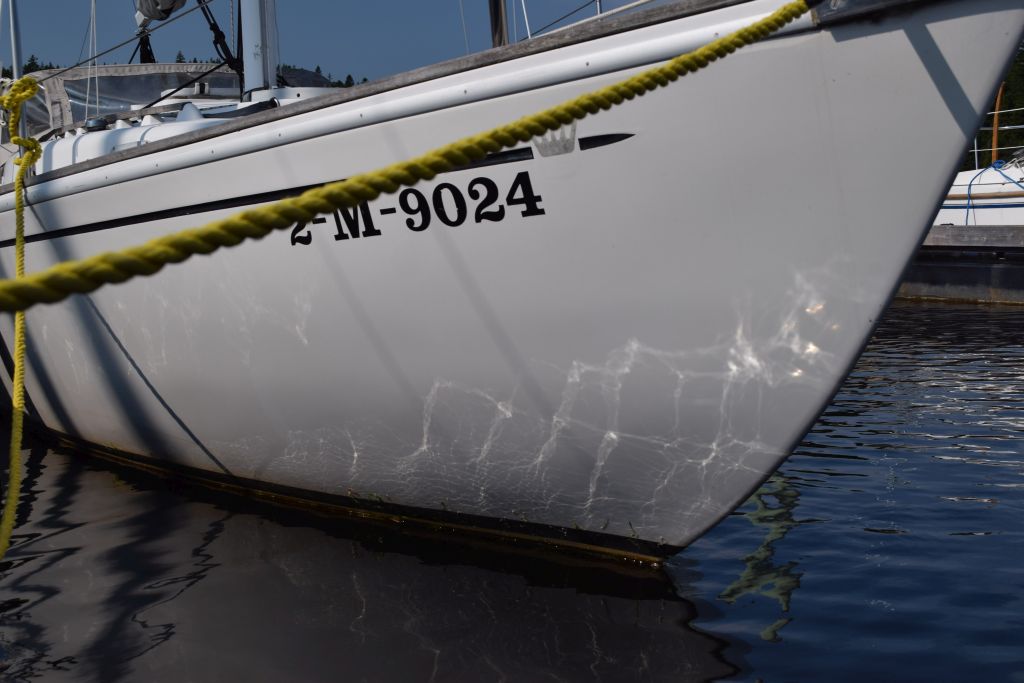
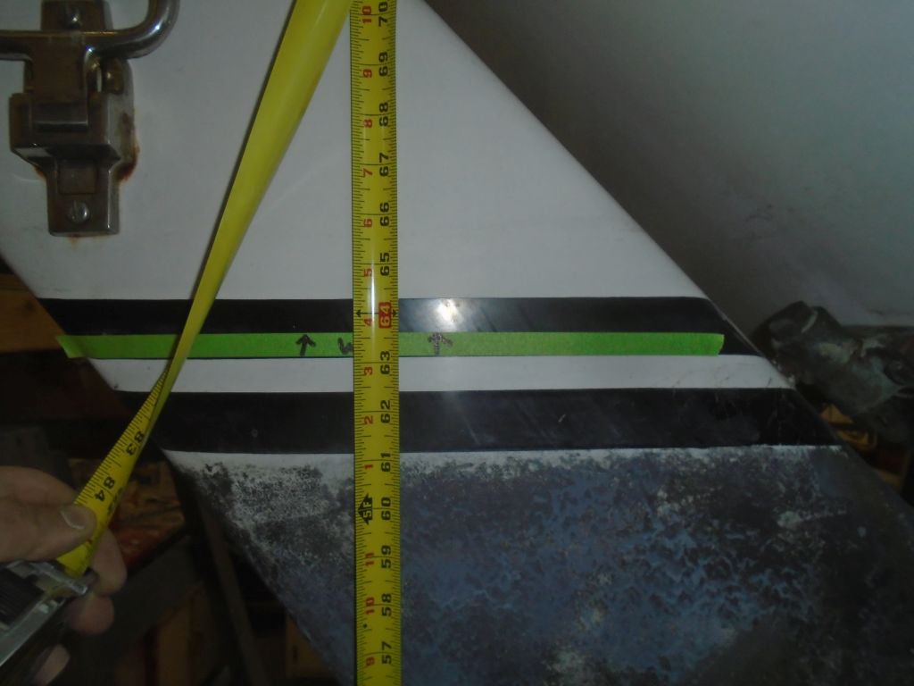
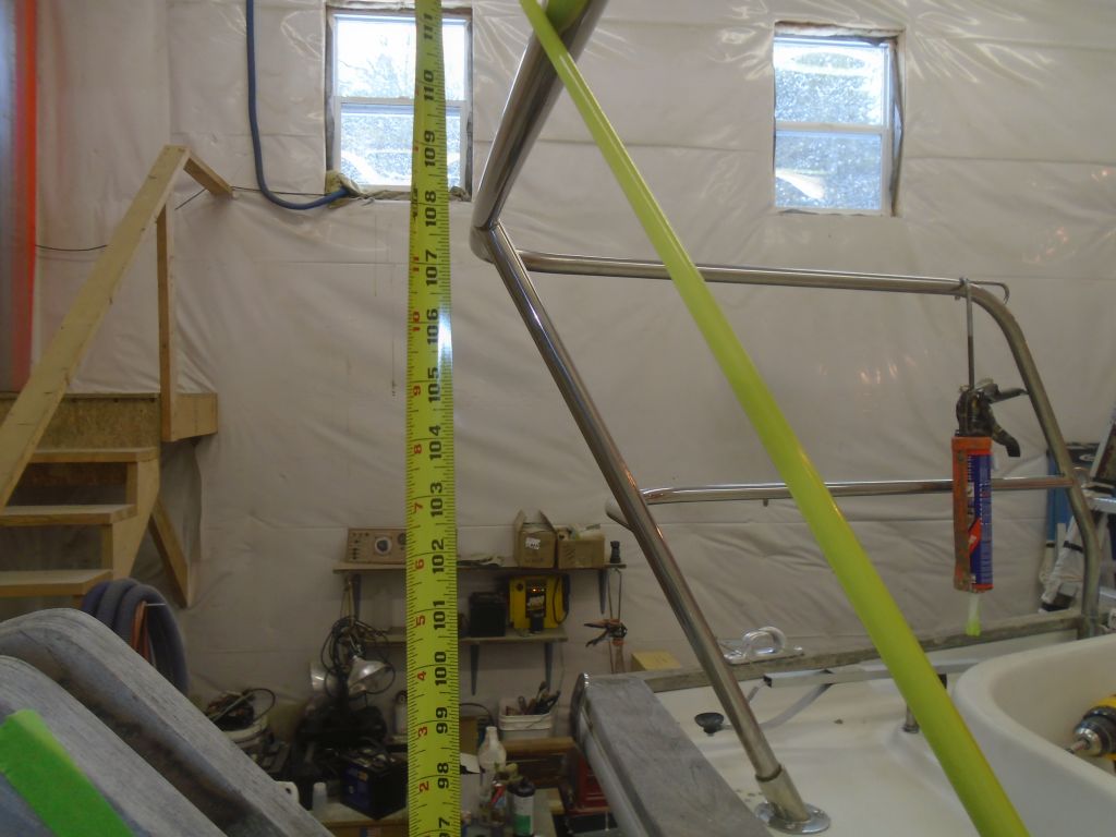
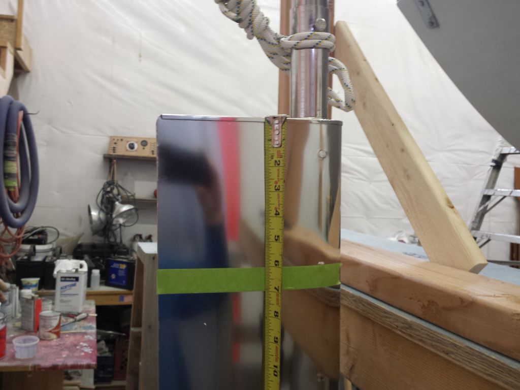
The final position of the windvane depended on the actual waterline: the center of the main frame tube was supposed to be 42″ above the boat’s waterline, which, with the overall dimensions of the various parts of the vane, would position the vane’s paddle in the correct position, with approximately six inches of the paddle above the waterline. There was a fairly clear idea of the actual waterline on the boat in the form of a scum line–it was (as past experience with sisterships suggested) well higher than the factory’s DWL–and the owner provided me with key photos showing the boat in the water, which confirmed what the scum line suggested. Working from the photo, and from the actual line on the boat, I marked the waterline position with masking tape. This mark was 63-5/8″ from the floor in this case, and now I could add the required 42″ to this to achieve the from-floor measurement of 105-5/8″ to the center of the main frame tube.

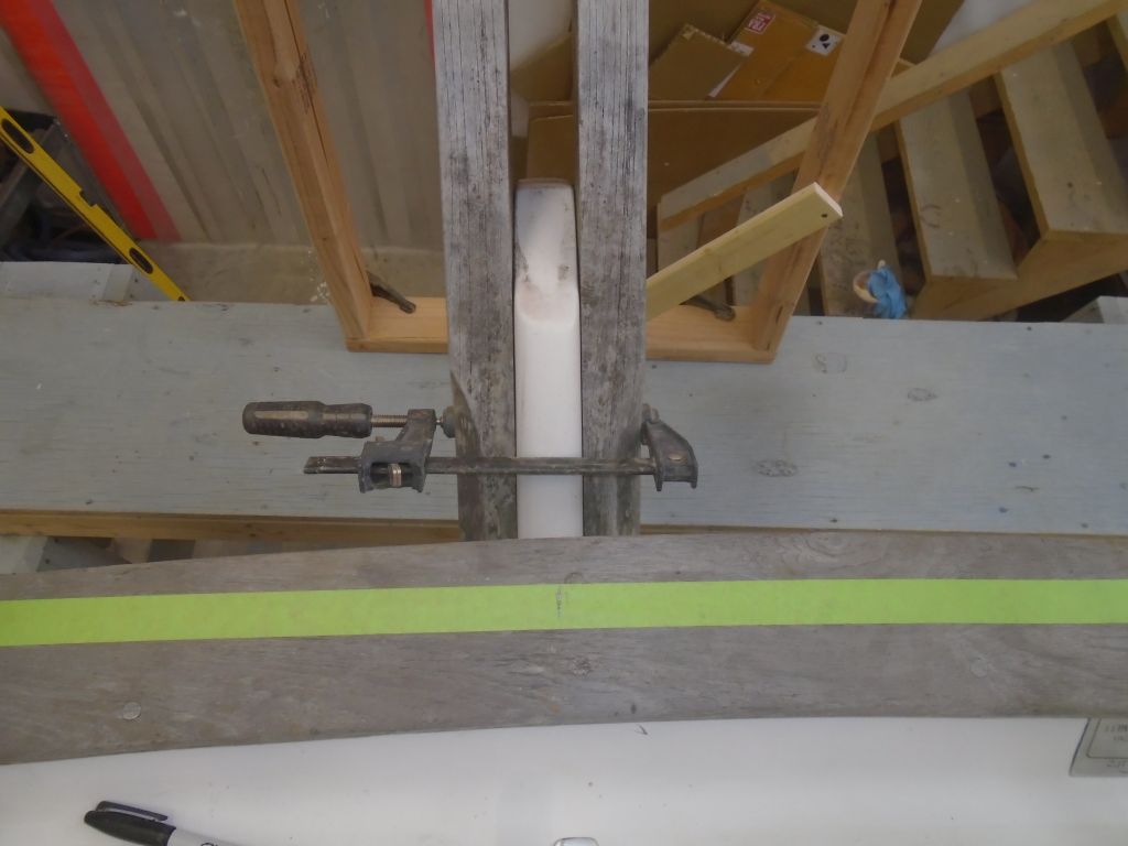
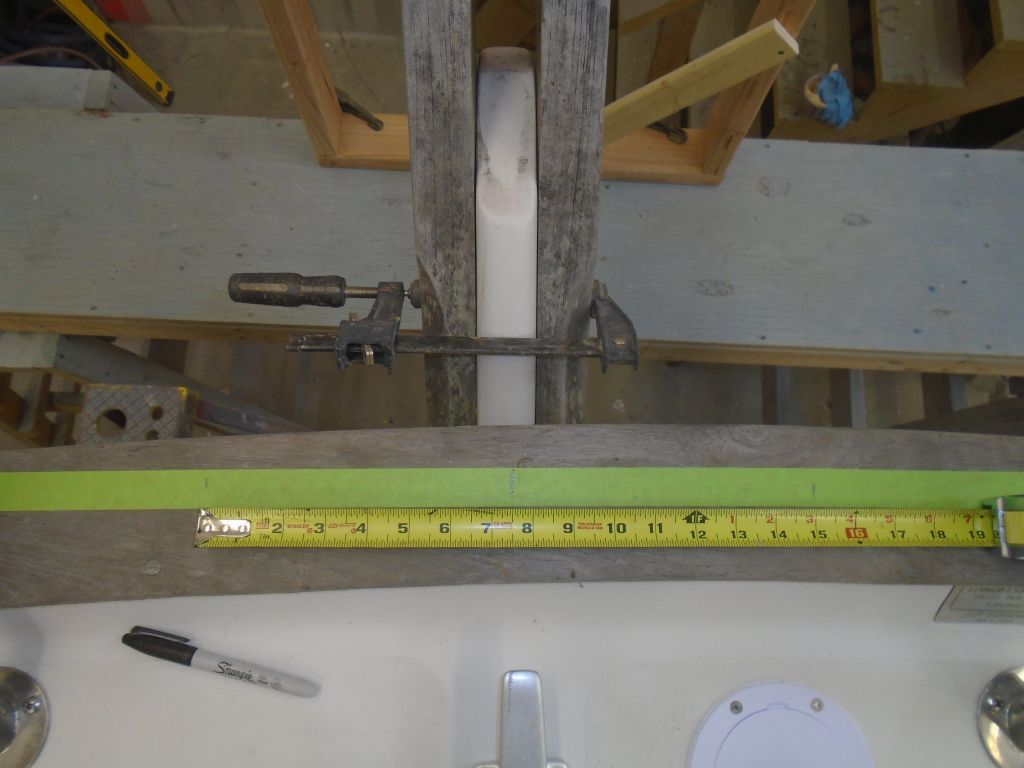
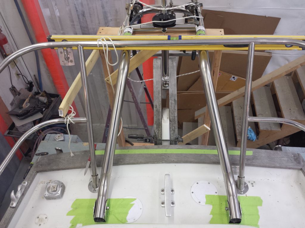
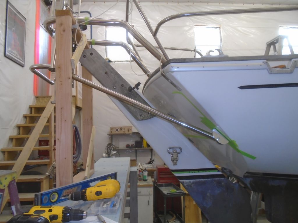
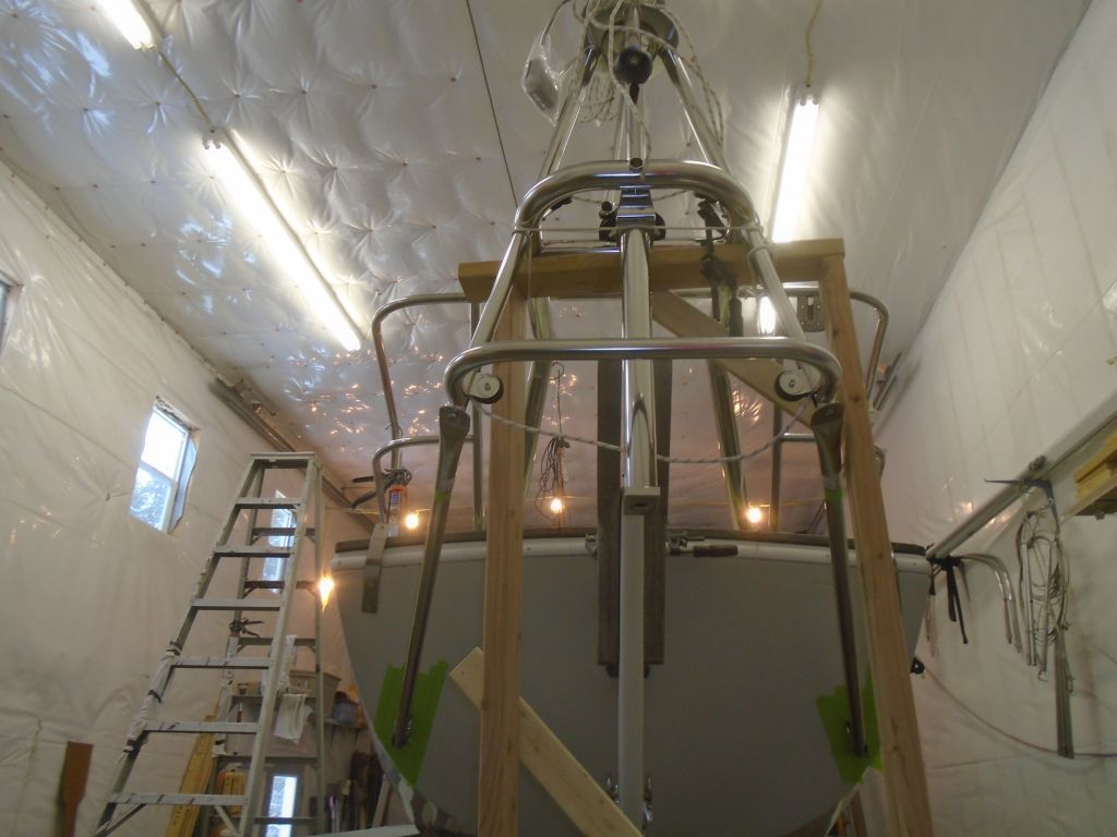
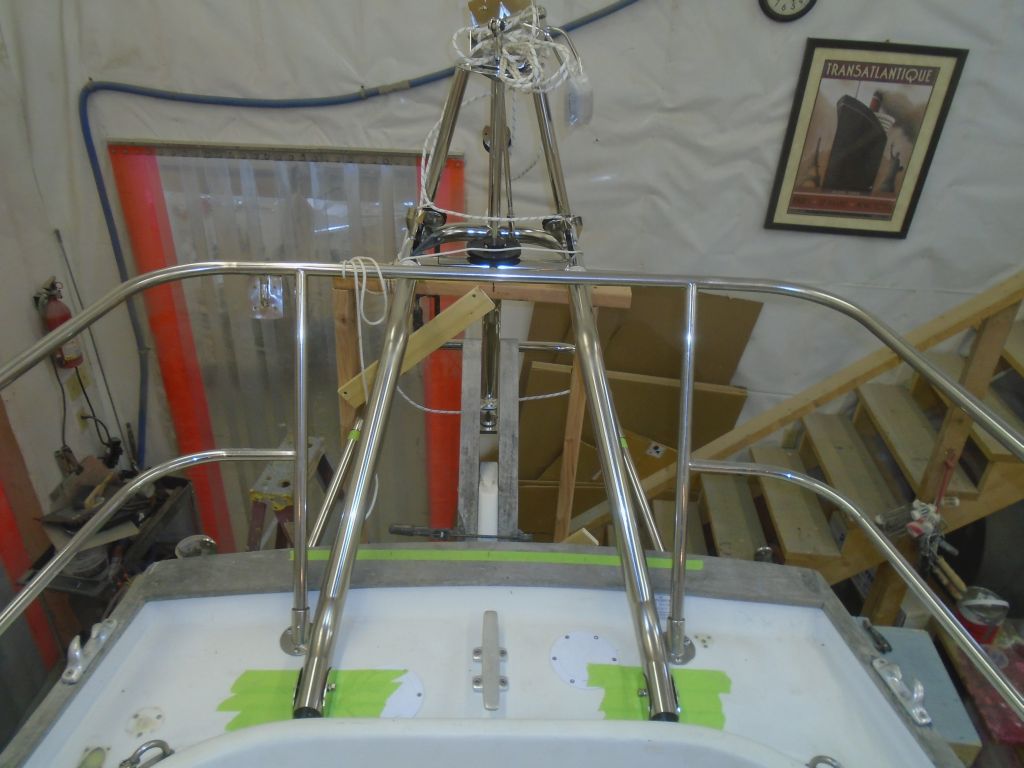
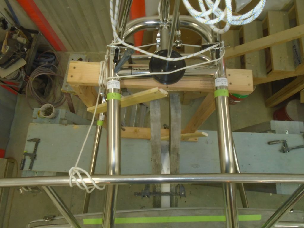
Now, working through a series of calculations based on the existing height of a staging platform that I set up behind the boat, and using the bottom portion of the vane’s frame as a support point (15″ below the main tube), I constructed a simple frame from 2x4s that, when added to the staging platform, would support the vane at the correct final height. On deck, using the center of the rudder as my guide, I made some basic marks to show the centerline and the centers of the main windvane support tubes (15″ on center, or 7-1/2″ on each side). As it turned out, I needed only the visual key of the rudder itself in this case, which was a far better centerline indicator than any measurement.
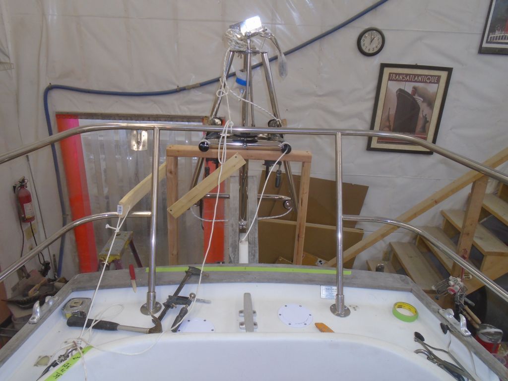
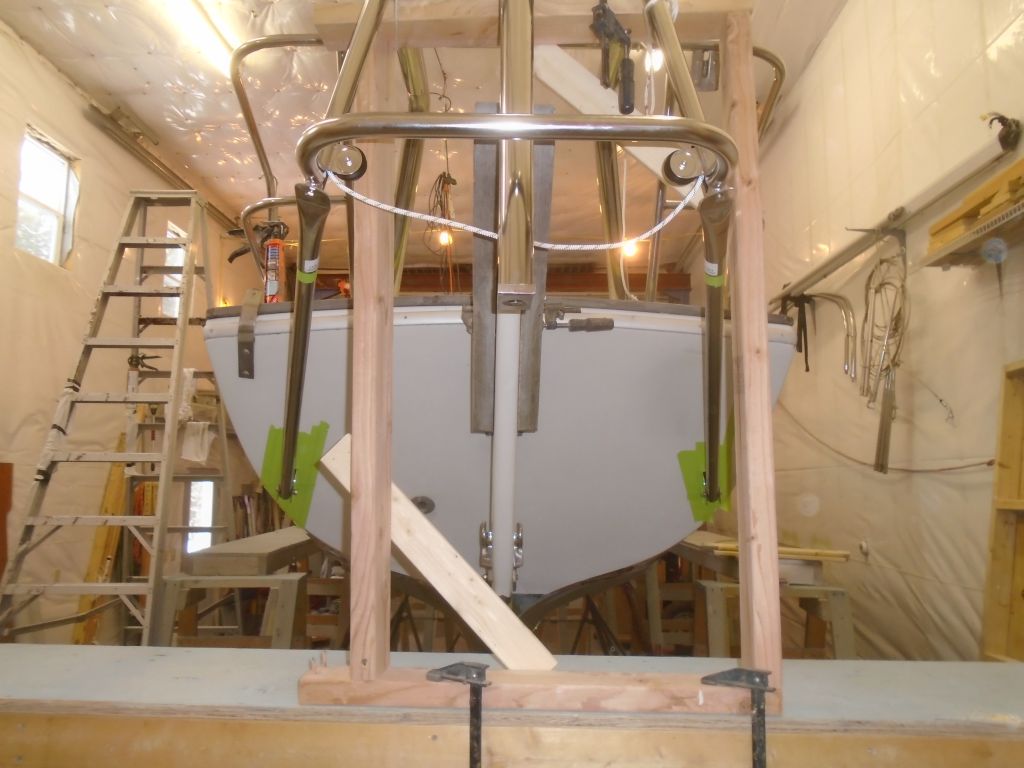
With my supporting framework secured to the staging platform, I moved the whole arrangement to roughly where I though the vane would want to be–as close to the top corner of the rudder cheeks as possible.
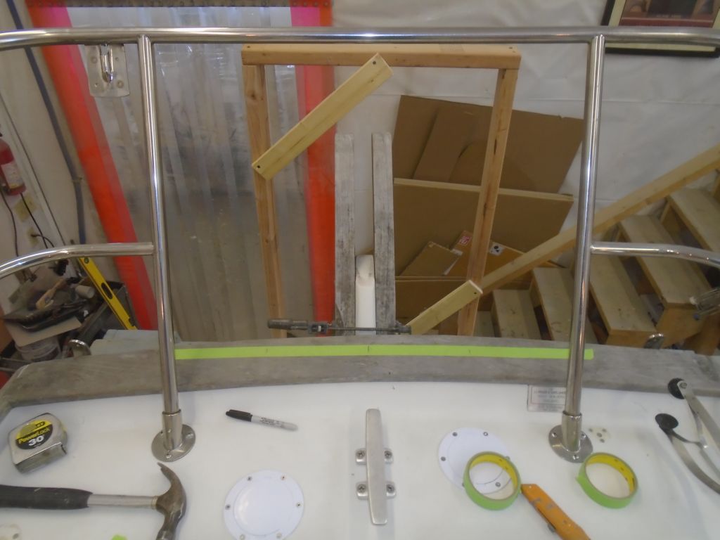
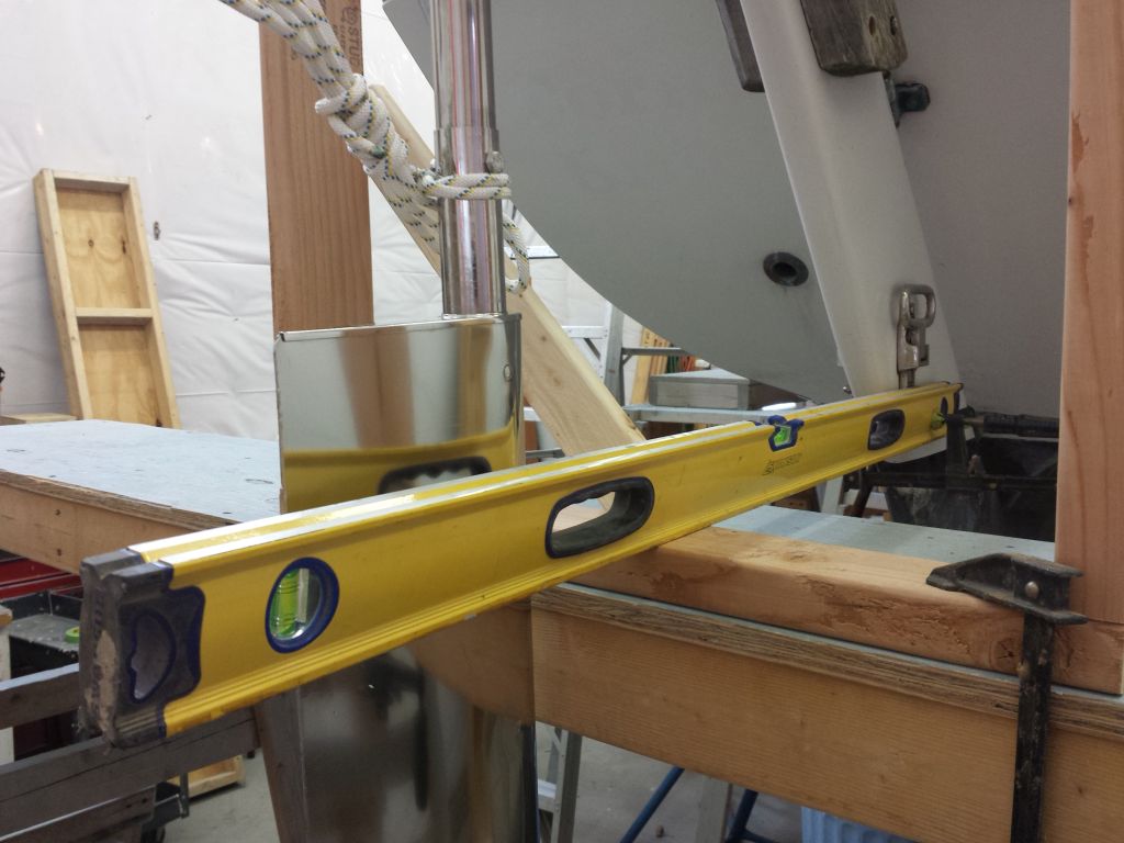
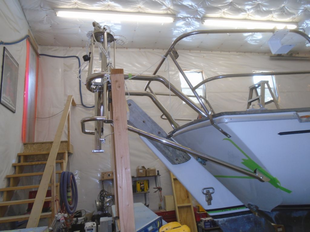
Next, I could rest the windvane frame itself on the platform and see how I did. I clamped the vane to the top support, and added a couple safety lines to secure the whole arrangement. The center of the tube was right where it should have been, or possibly just a touch higher, which is the direction I wanted to err anyway.

I temporarily installed the vane paddle, and, with a level, extended the waterline mark aft so I could put some corresponding tape on the paddle and confirm that the vane’s position was correct and in accordance with the supplied drawing for this boat. It was.
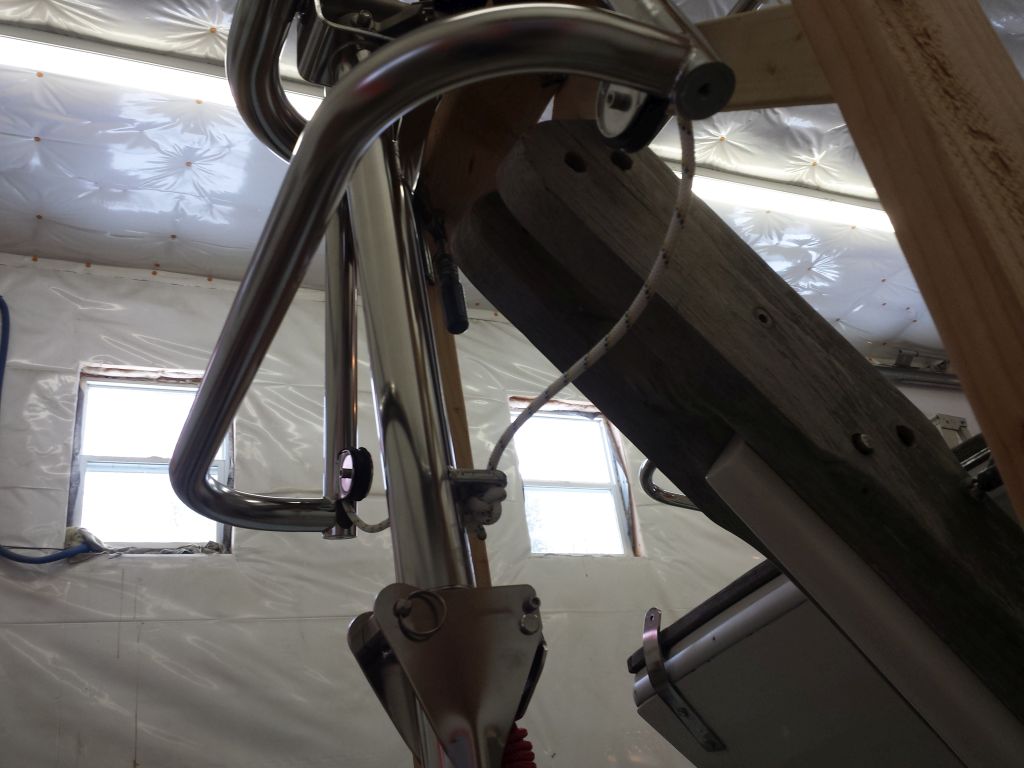

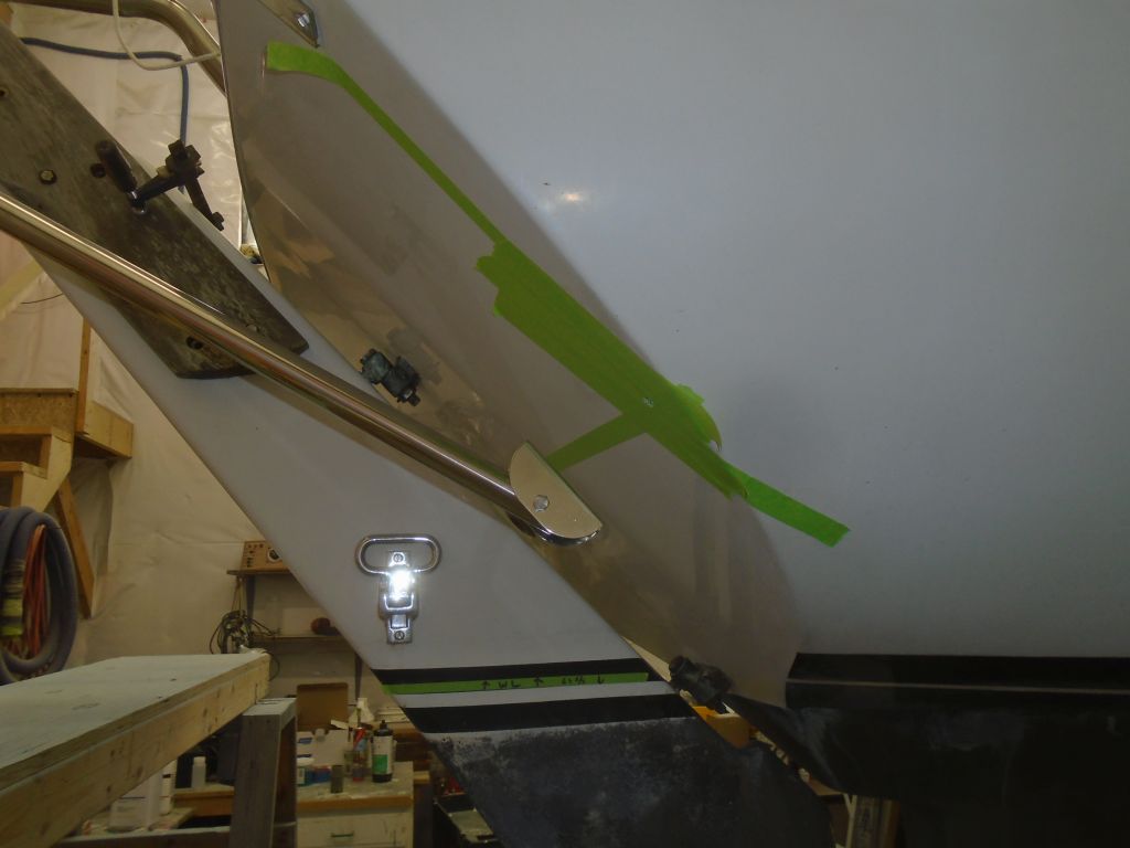
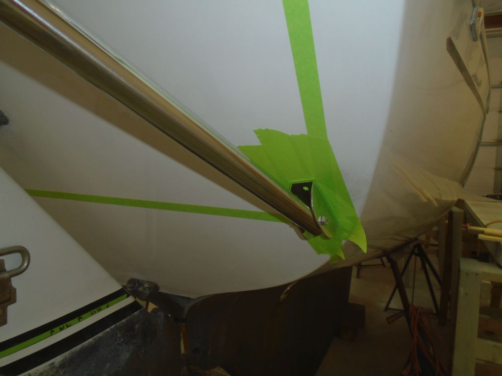
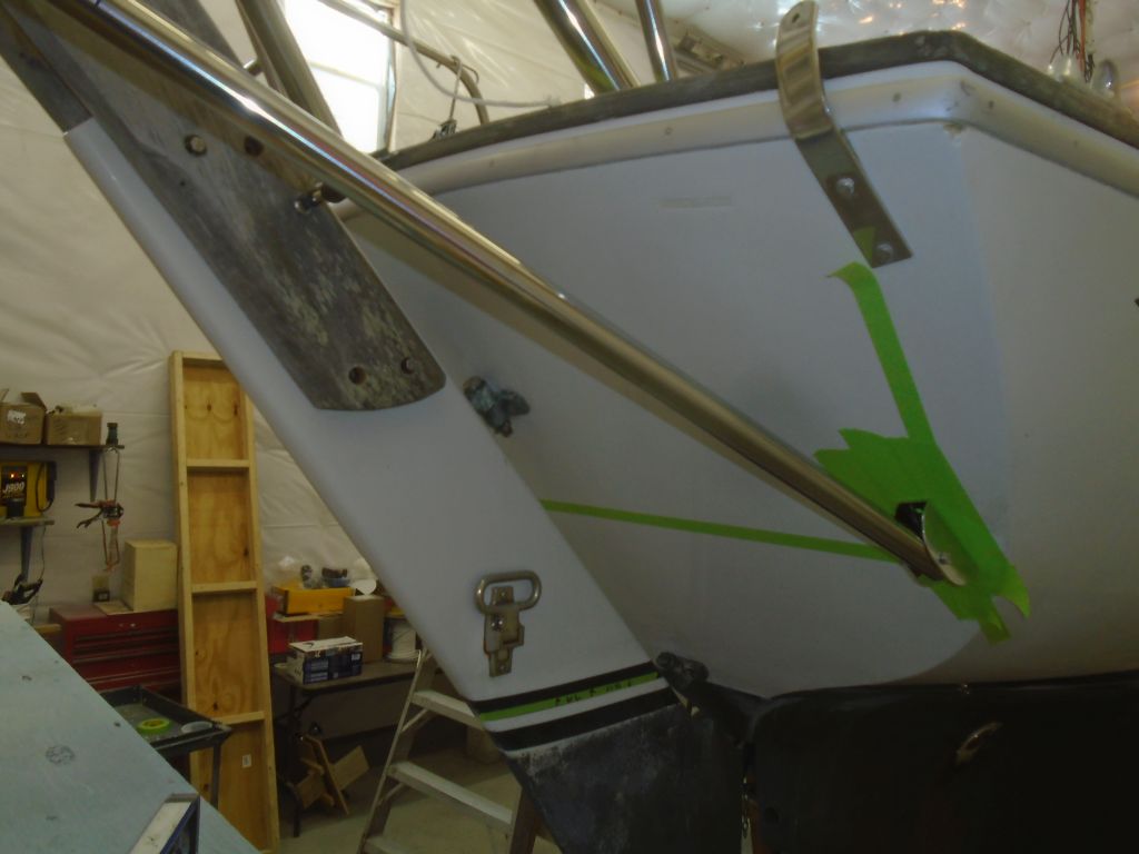
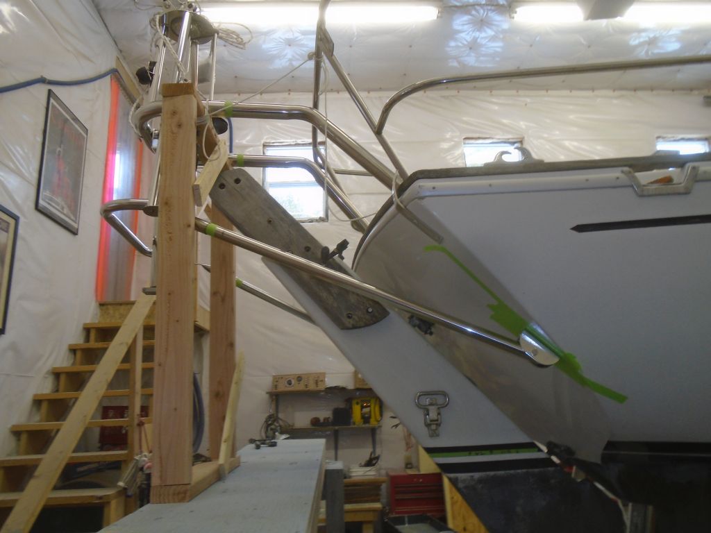
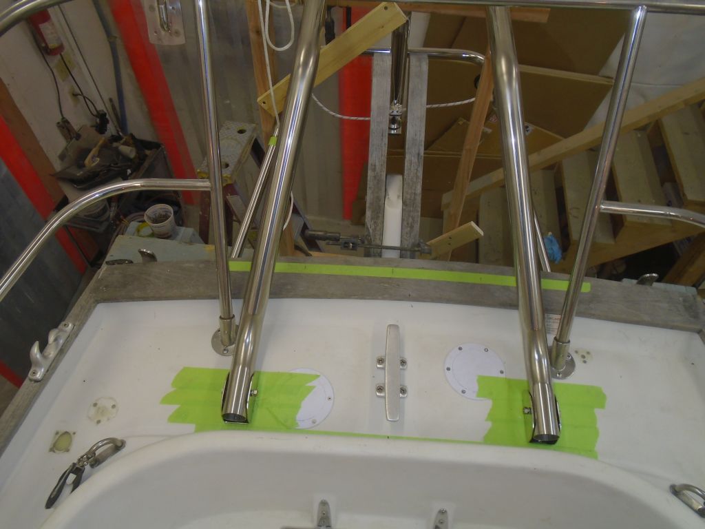
Starting with the large upper support tubes, I worked through the installation steps as required. ON this boat, the upper tubes were deck-mounted, and featured a bent shape to accommodate the vane’s position relative to the boat. Based on where I had the vane positioned vis-a-vis the rudder, I could shorten the tubes a bit, something that was encouraged (as necessary) by the manual with the ultimate goal of keeping the vane as close to the boat as possible–or, more specifically, no further away than strictly necessary, So with the mounting brackets temporarily in place, and the support tubes set in, I marked the excess length and also marked for a through-bolt that would secure the tubes to the mounts. With these basics, I could temporarily secure the mounts to the deck; I’d have to come back and properly prepare the mounting holes and ultimately secure the mounts with sealant, but for now I secured them directly to the deck with tapped holes. With the tubes cut to length, and the through-pin holes drilled, I secured everything in place temporarily. Throughout this process, I strove to ensure that the vane was level in both directions, and properly centered on the rudder.
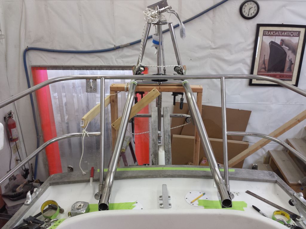
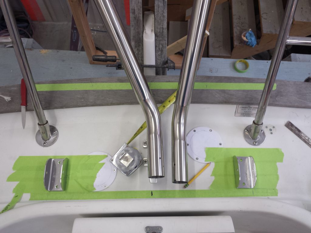

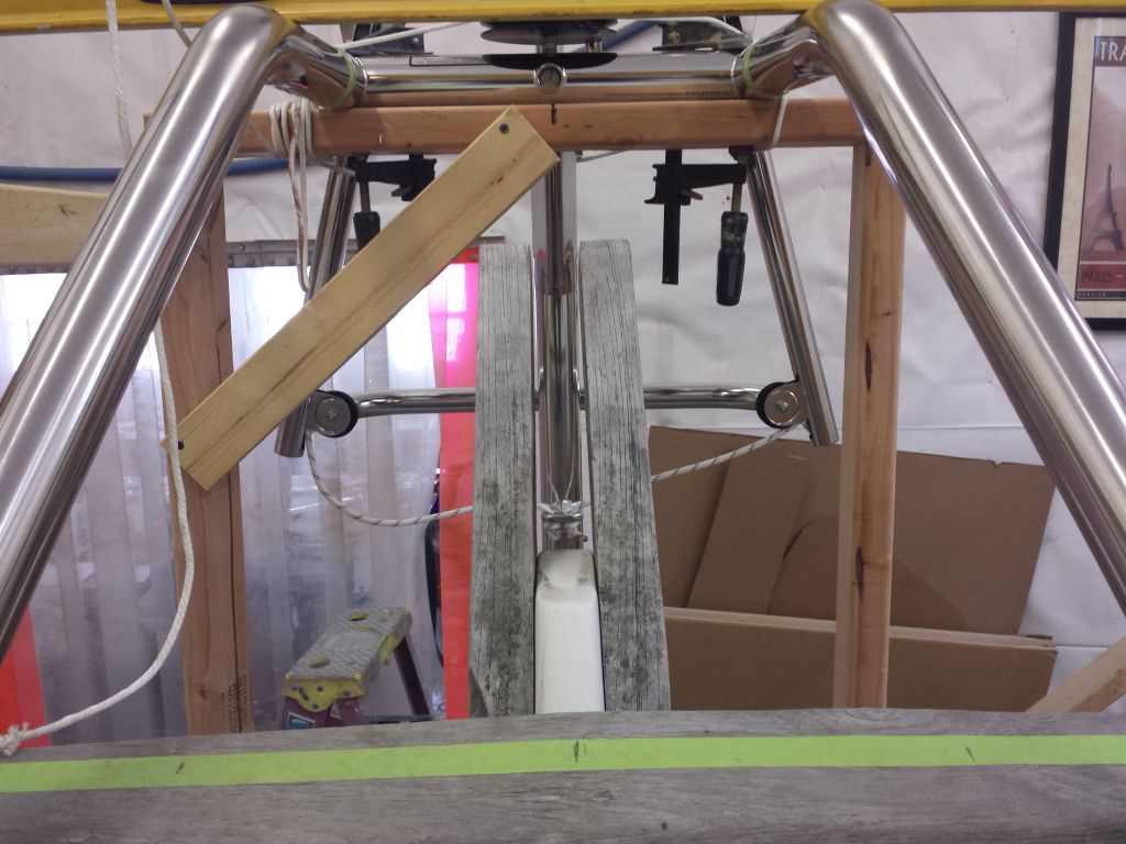
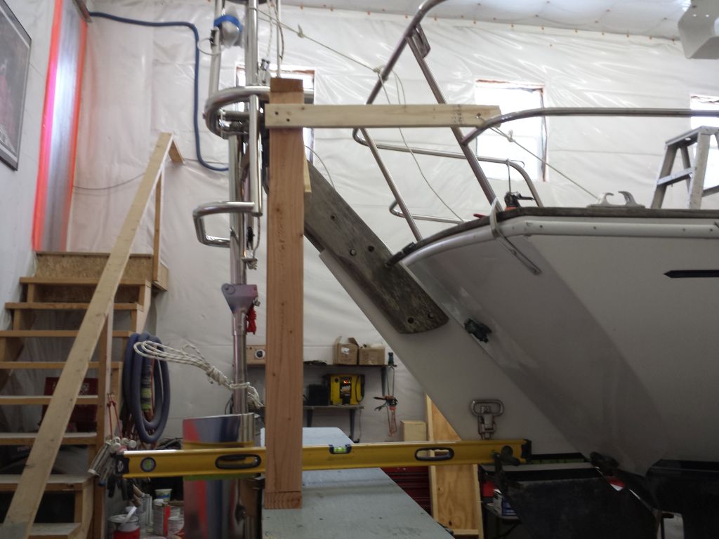
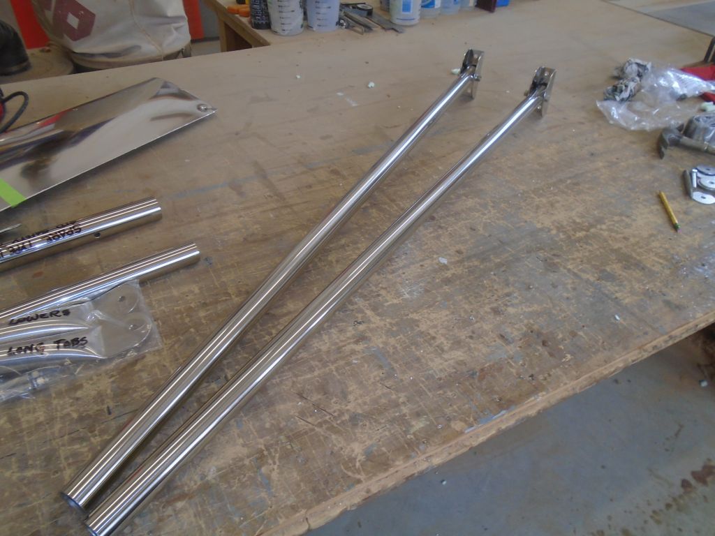
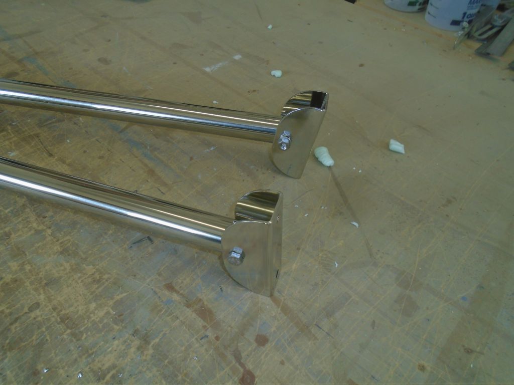
Sometime later, I’d have to drill holes through the vane end of these tubes to secure them there, but for now I was ready to continue with fitting the two lower braces, which would run between the bottom of the frame and the transom. The provided tubes were pre-drilled at the end to fit into the brackets–something that was normally done for the upper tubes as well, except in cases like this where the final mounting position couldn’t be pre-determined–and would fit into a socket end at the frame, which bolted right to the bottom of the frame in a threaded hole. Using various guidance from the manual and mounting diagram for this boat, as well as photos of other installations, I determined that the lower tubes as provided were overlong, so once I figured that out I could start to position the brackets on the hull, and from there determine the final length of the tubes.
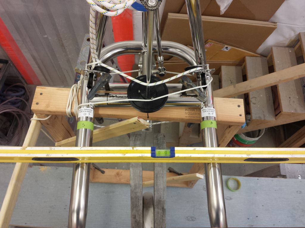
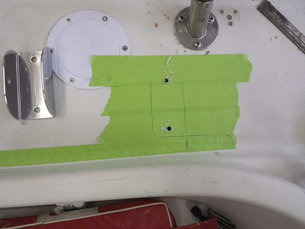
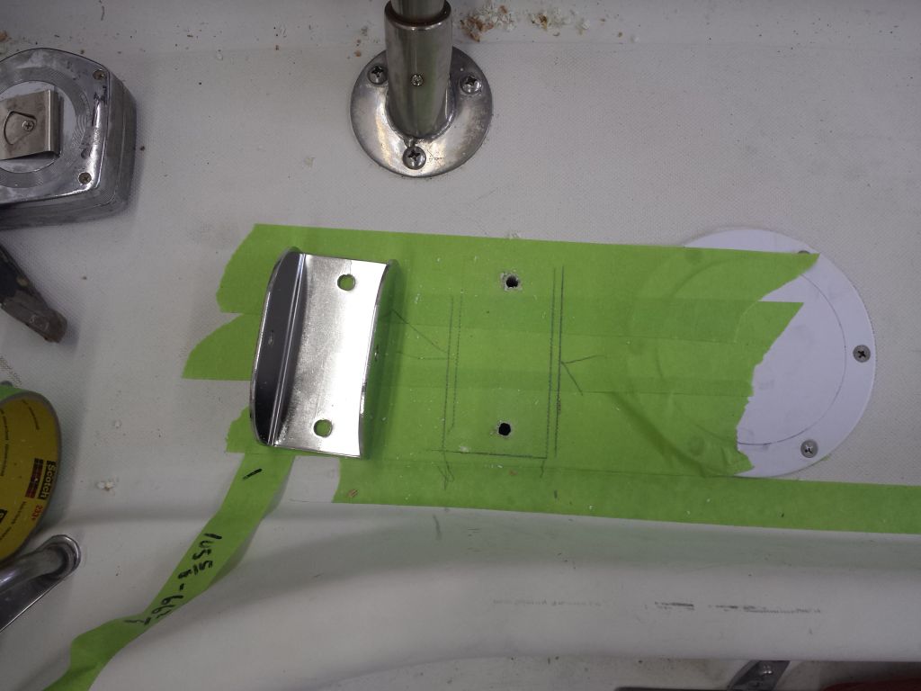
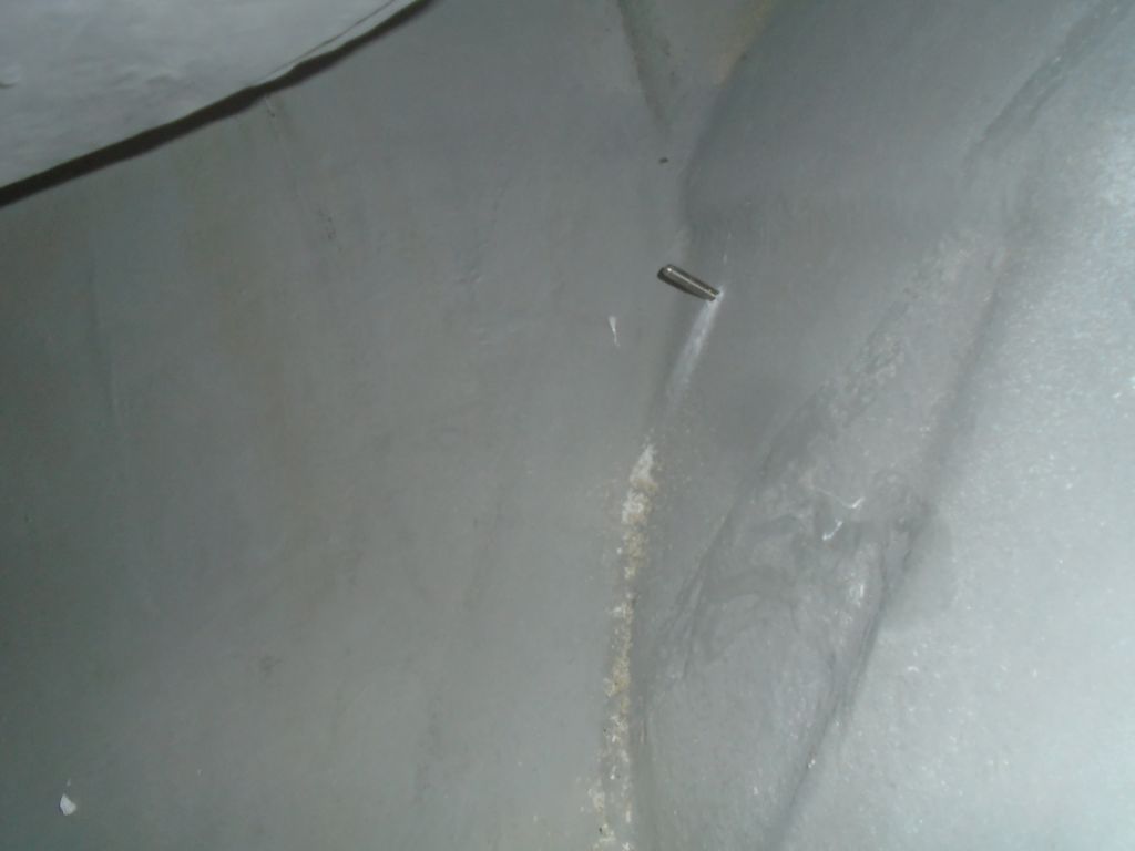
Starting with the starboard side, I held the pieces in place as needed to determine where the bracket should mount (the tube should angle down about 15° from the frame, and outboard the same amount–with the extra guidance of about 45″ between bracket centers, according to the diagram. These criteria helped me determine roughly where that bracket should be, though none of the dimensions were absolute, Then I could figure out where to cut the tube, which I did next, and dry fit it in place so I could begin to secure the bracket on the hull. For now, I drilled and tapped the lower bracket hole to accept a 5/16″ bolt. The upper hole was blocked by the tube itself, and I marked the position of the bracket so that later I could return and prepare the second hole.
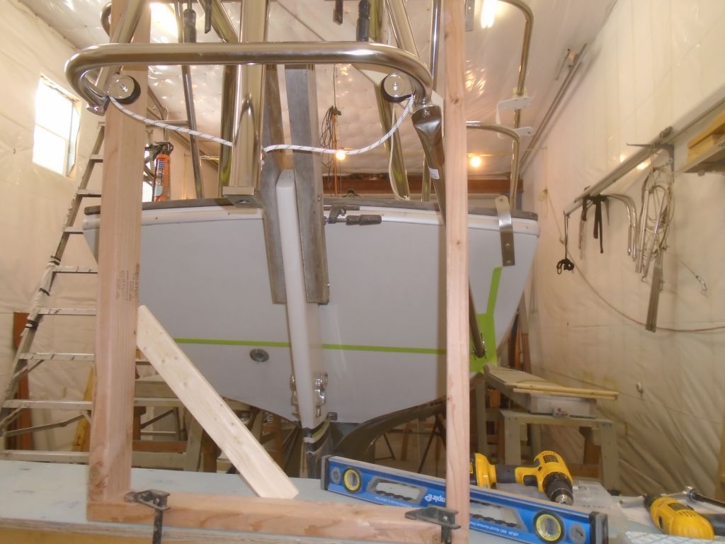
I repeated the process on the port side, though I first had to modify my wooden support frame a bit, as it blocked access to the point on the frame where the tube needed to go. I’d used an arbitrary piece of lumber to determine the width of my wooden frame, and this was just a bit too wide. I cut another vertical support and installed it further inboard, then removed the offending piece for clear access to the vane’s frame base.

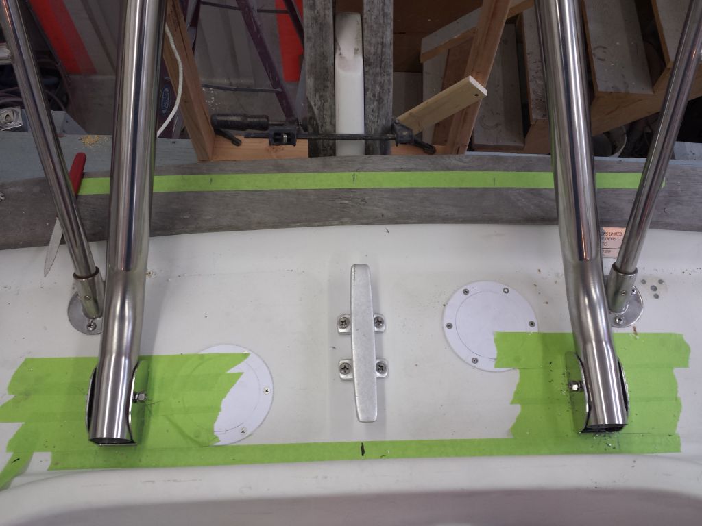
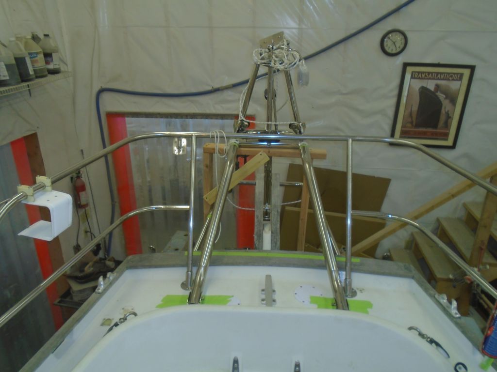
I could have just cut off the second tube at the same length as the first, but because boats are frequently asymmetrical, I thought it’d be better to go through the various dry-fitting steps as I did before, though this t ime I had a known point on the transom for the bracket. As it happened the tube ended up exactly the same length, and before long I had it temporarily installed as well.

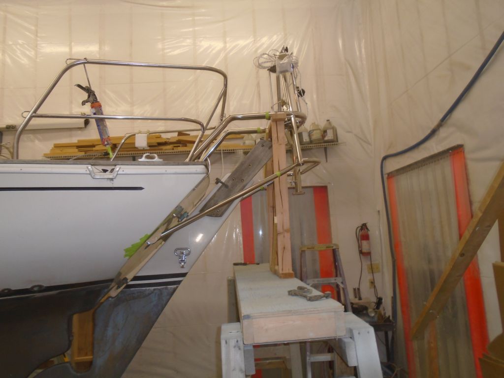


These four tubes formed the main support structure for the vane, but there was also a pair of diagonal supports that I’d install between the bottom of the vane (where the lower tubes attached) and the upper support tubes. But it was the end of the day, and I’d continue with that next time. Though I’d felt like the installation process had gotten off to a slow start–intangibles like layout and instruction-reading somehow seem like anti-progress, though I know they’re not–I was pleased with the vane’s installation status by the end of the day, and there was no doubt that it was an impressive and artful piece of hardware.
Total time billed on this job today: 8.5 hours
0600 Weather Observation:
Snow, moderate. Forecast for the day: snow, 3-6″ predicted, ending in the afternoon and clearing.