

March 26, 2016
Salty 27
Saturday
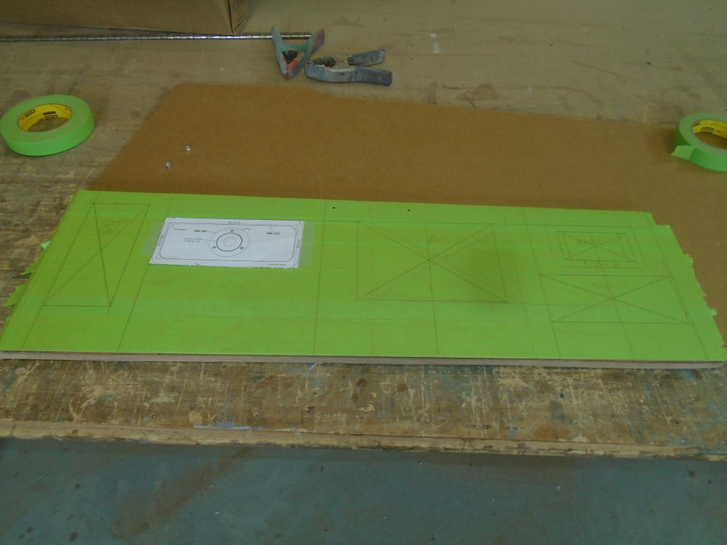
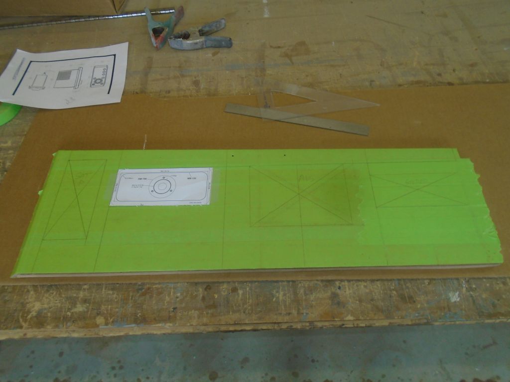
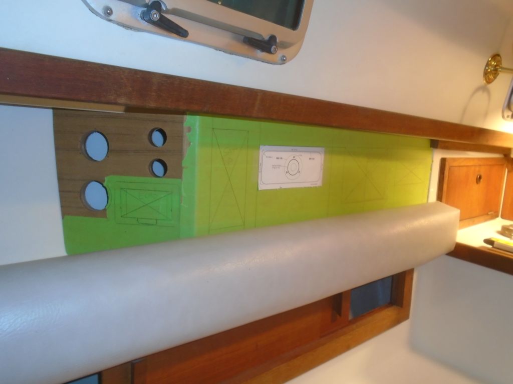
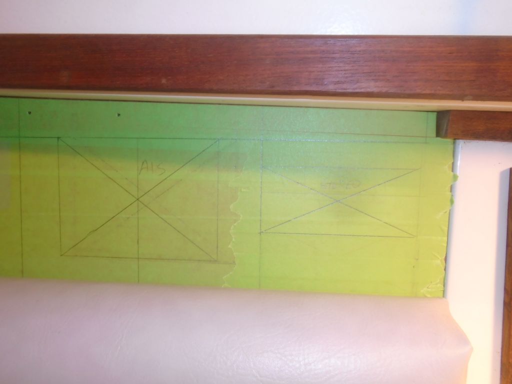
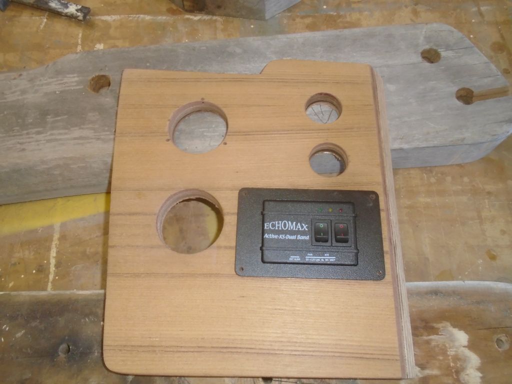
At my request, the owner provided me with a quick sketch of his proposed layout for items in the new electrical locker, which I used to lay out the actual sizes of the listed equipment on the panel, which I covered with tape for layout purposes. I tried to leave a full 3″ buffer at the bottom, plus more than an inch at the top, to account for support cleats, hinges, and other obstructions (like the backrest) Then, I test-fit it in the boat with the backrest in place to see how it worked out in reality.
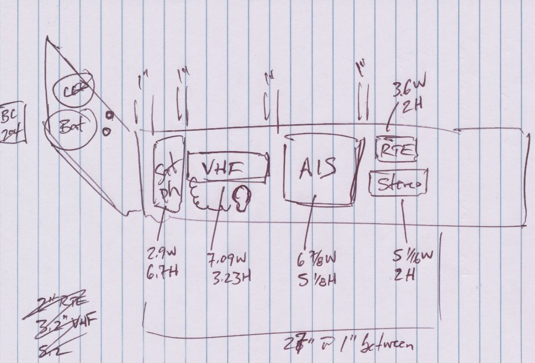
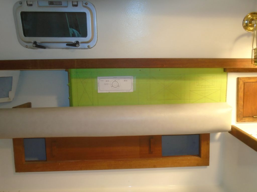
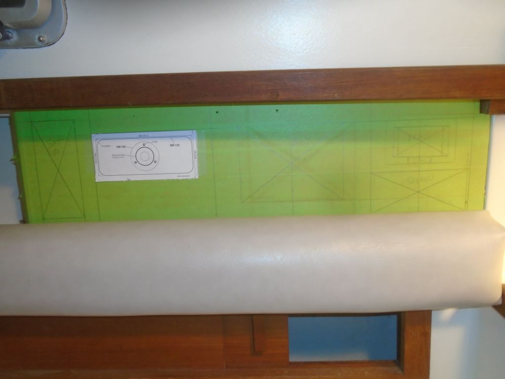
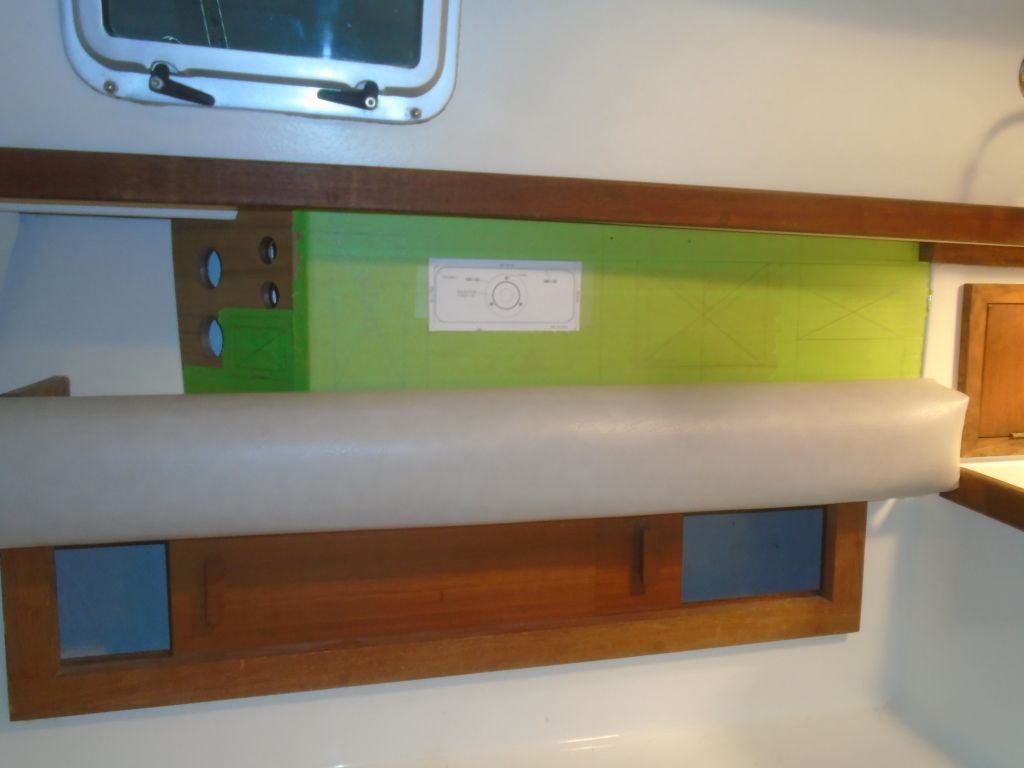
While it would work with this layout if necessary, the two items at the forward end were pretty scrunched in, and the stereo was lower than ideal, and partially hidden behind the backrest. I thought it might work better if I moved the small control box at the top (for a masthead unit combining a radar target enhancer (RTE) and an anchor light) to the angled after panel, where it could share space with the battery monitor and other installations, and this would open up the forward end of the large panel for the stereo to move up. This seemed to work better, and the owner approved the change, though with final decisions still pending on some of the installations and whether or not they would happen nor or in the future, we decided to wait on cutting any of the large panel till later.
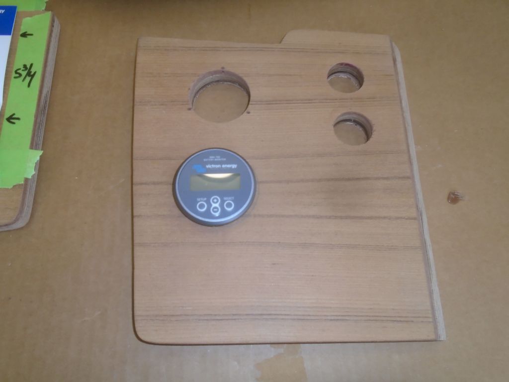
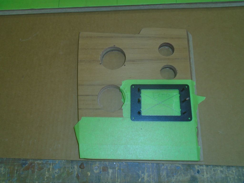

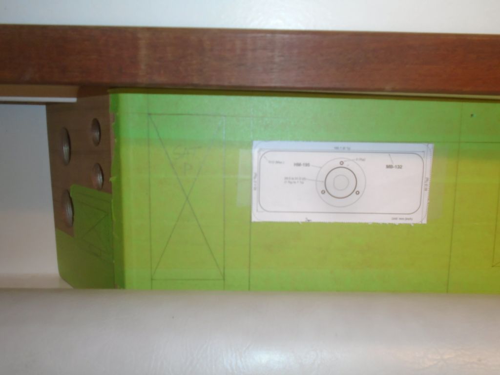

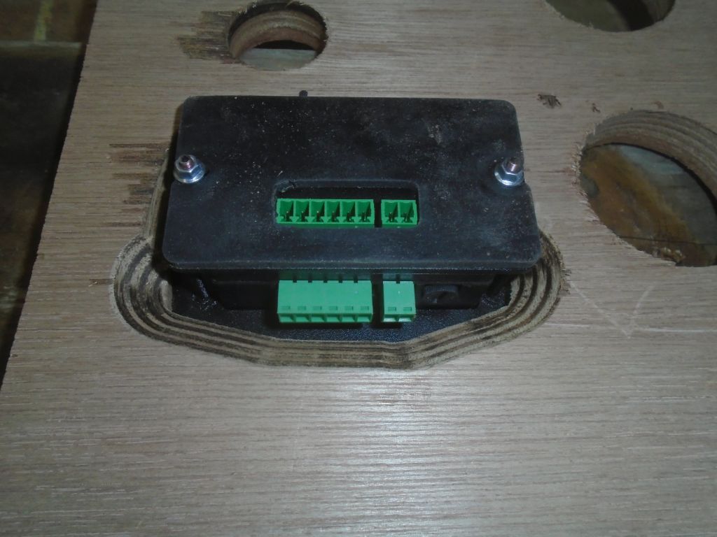
Still, I could proceed with the cutout for the RTE in the angled panel. Using a supplied flush mount kit, I laid out the opening and cut it as needed. The flush-mount kit and control box itself appeared to have been designed for a thin metal panel, and the way the wiring connections to the control box worked required that I expand the cutout on the bottom edge–basically extend it as far down as I could while still allowing the coverplate to cover the hole–and even use a router with a chamfer bit to pare away material on the back side to allow access to the wiring block on the control.
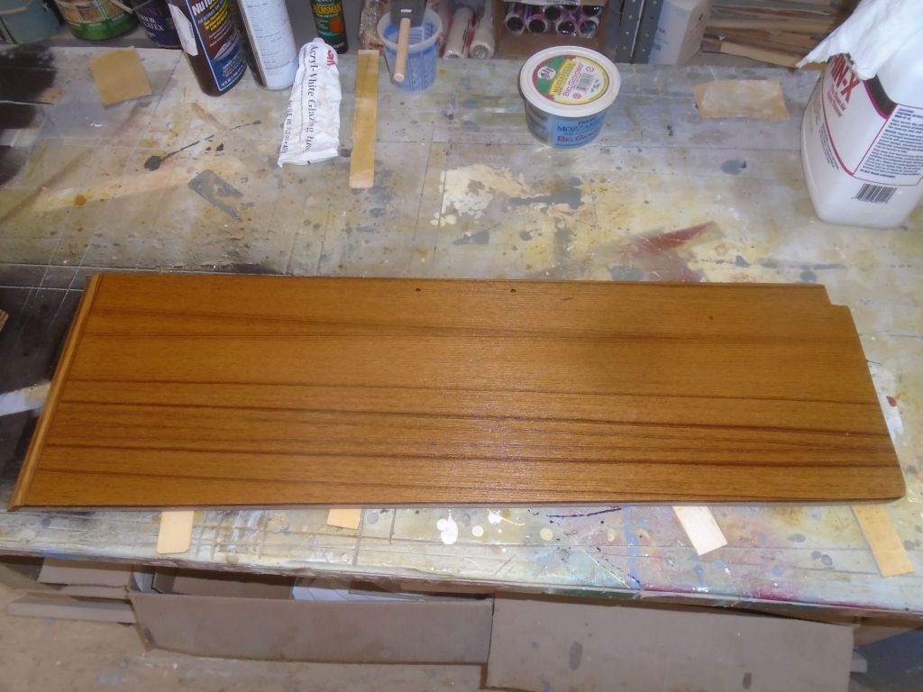
With the panels complete for now, I lightly sanded as needed, then applied coats of teak oil to match the other woodwork.
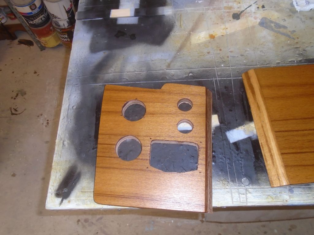
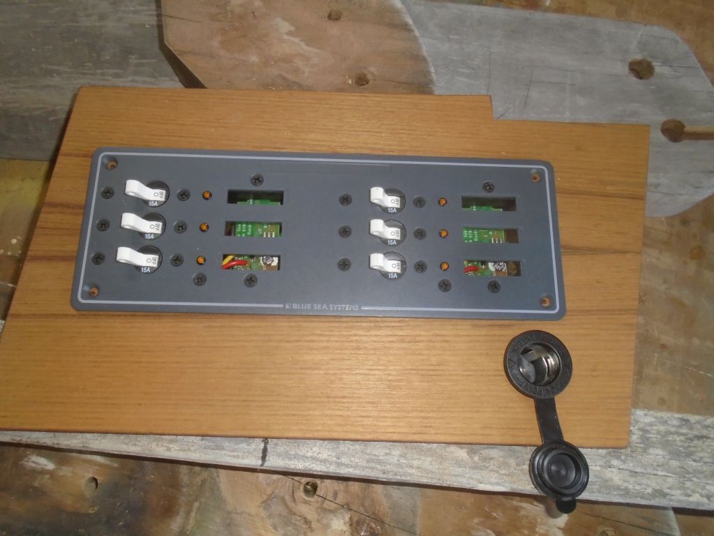
The owner re quested a second 12V outlet on the port electrical panel, so I went ahead and prepared the opening for that now.
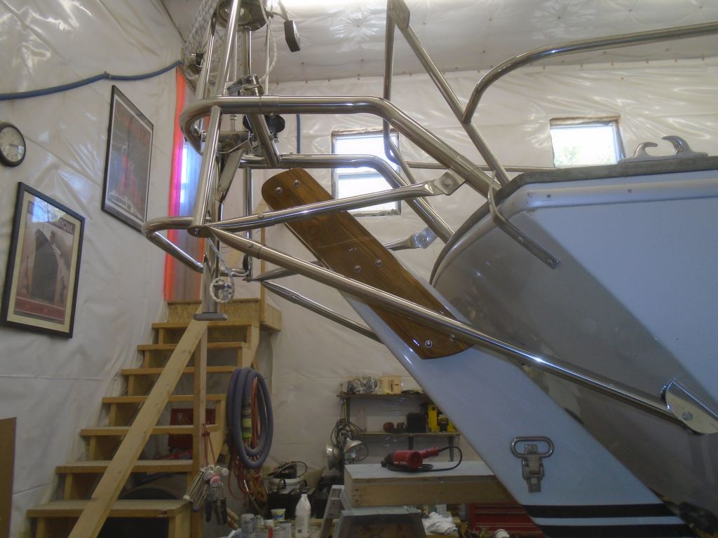
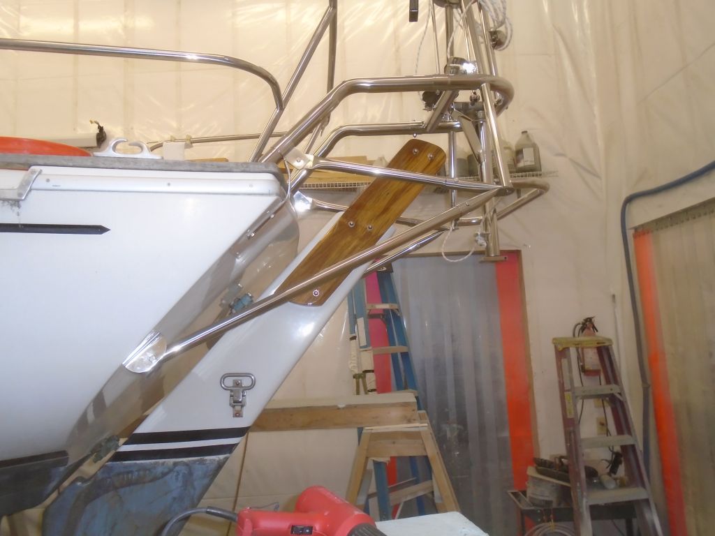
Later, I installed the new rudder cheeks, now that their varnish work was complete. I thought I could install the side pieces loosely, then insert the center part at the top, but this didn’t work well at all, so after some frustrating moments I removed the cheeks and pre-assembled the three sections on the bench before installing the whole assembly on the boat. The whole process was more difficult than I imagined it could be, since, despite having copied the original cheeks exactly–including the bolt holes–I had trouble aligning things, and had to ream out the bolt holes, which had gotten some varnish in and didn’t make it easy to install the threaded rod.
In the event, I got the cheeks installed with new stainless steel threaded rod and acorn nuts on both sides. What I thought would be a 5-minute job ended up taking over 30 minutes, but why this sort of thing continued to take me by surprise was the only real question.
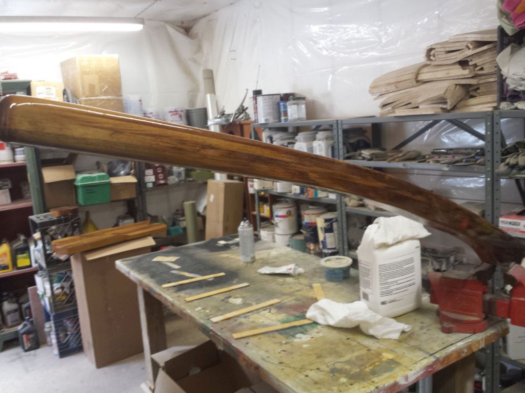
After the usual light sanding, I applied another coat of varnish to the tiller.
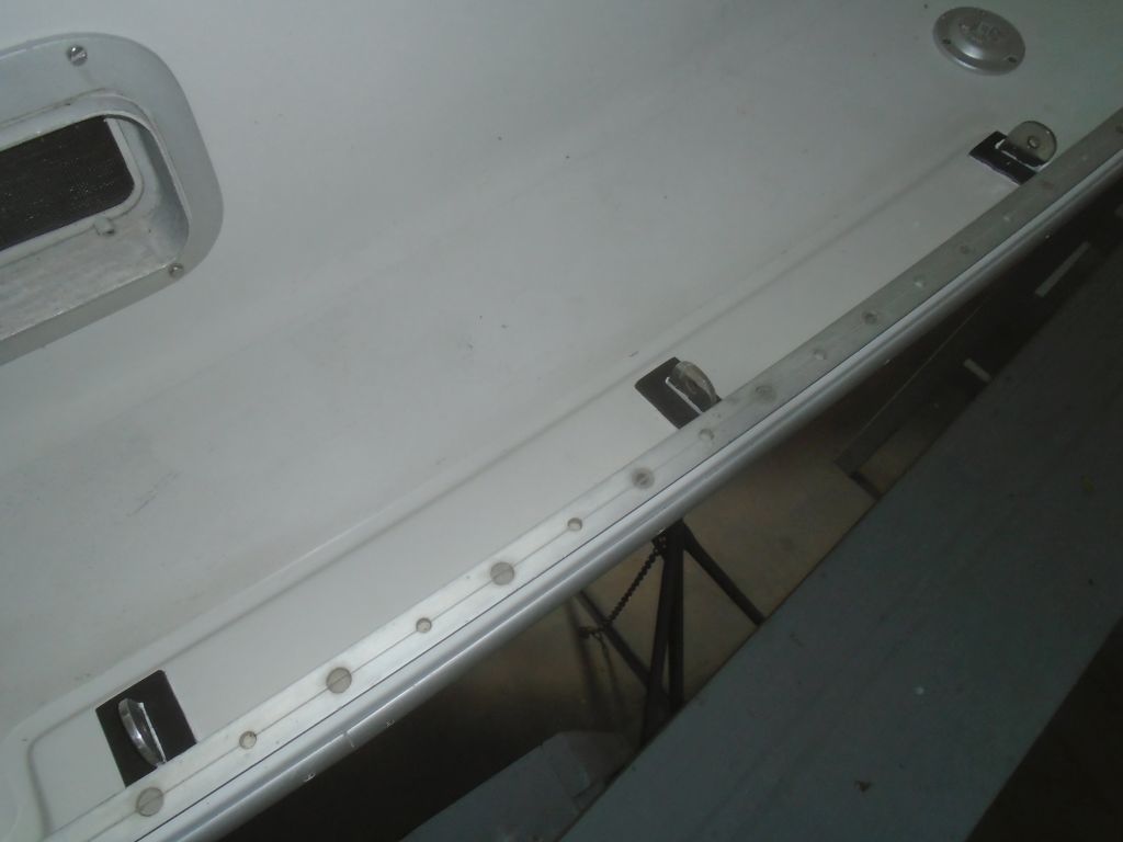
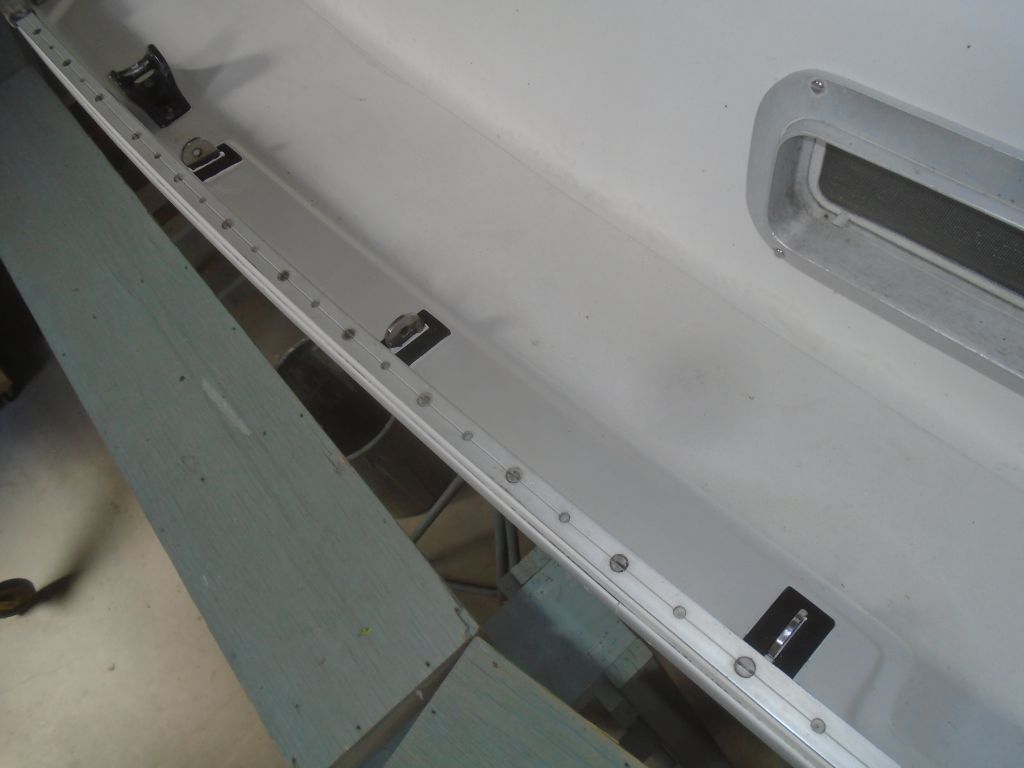
Continuing with various small and loose ends, I cleaned up the excess ( and now-cured) sealant from around the chainplate covers.
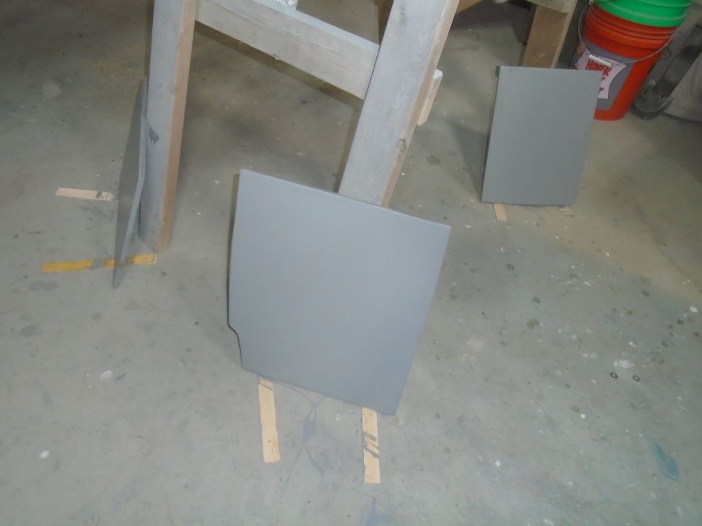
Meanwhile, I applied a coat of paint to the battery box pieces.
Total time billed on this job today: 4.25 hours
0600 Weather Observation:
30°, cloudy. Forecast for the day: Clearing, high in the low 40s