

March 13, 2016
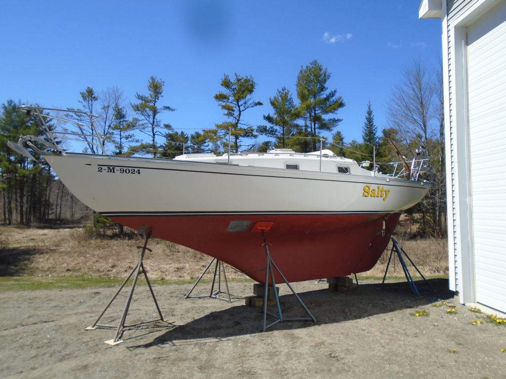
Salty 15
Sunday
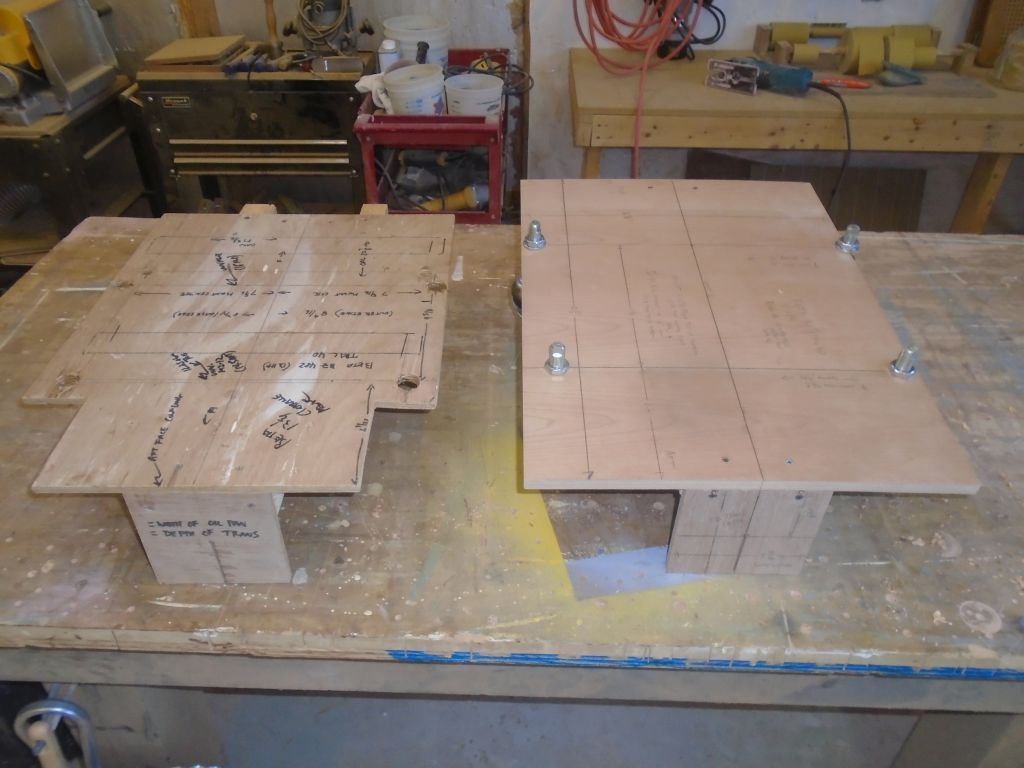
With some time on hand, I thought I’d take care of a couple small jobs, starting with a new engine installation template. I’d had on hand an older template, left over from another Beta 14 installation some time ago, but the template was in rough shape and had been modified (I’d used it for some initial engine calculations on this project as well), and there had been some changes in the design of the engine since that time.
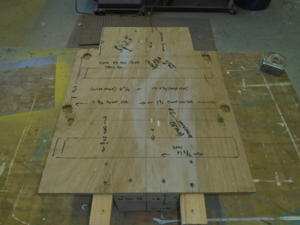
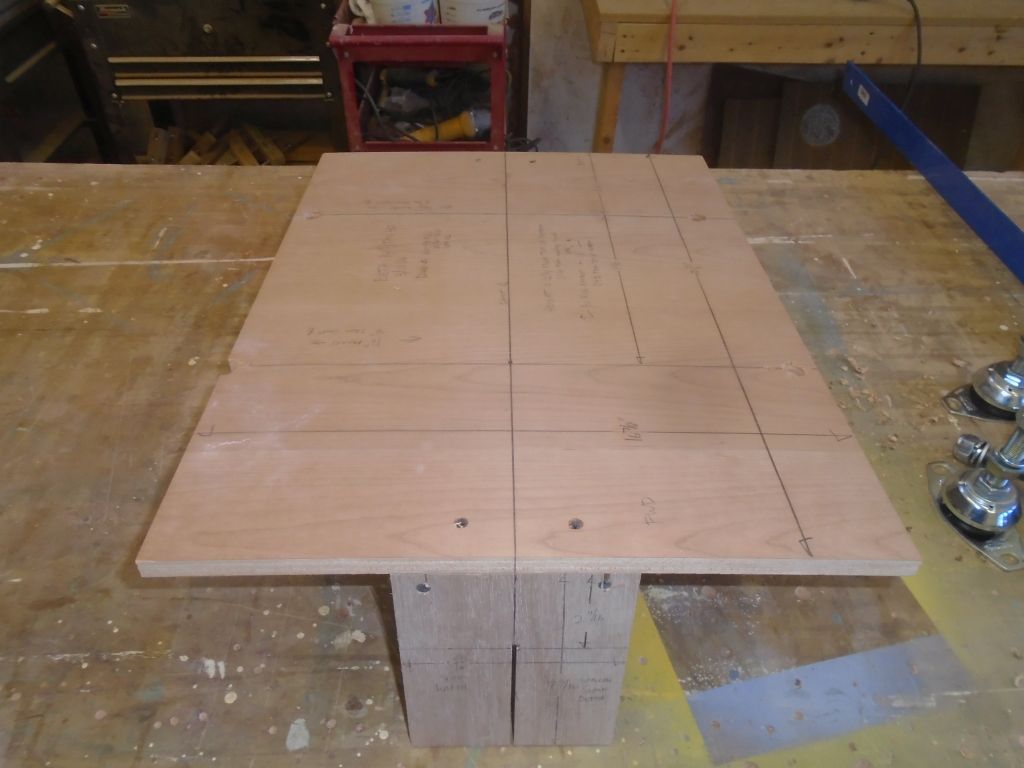
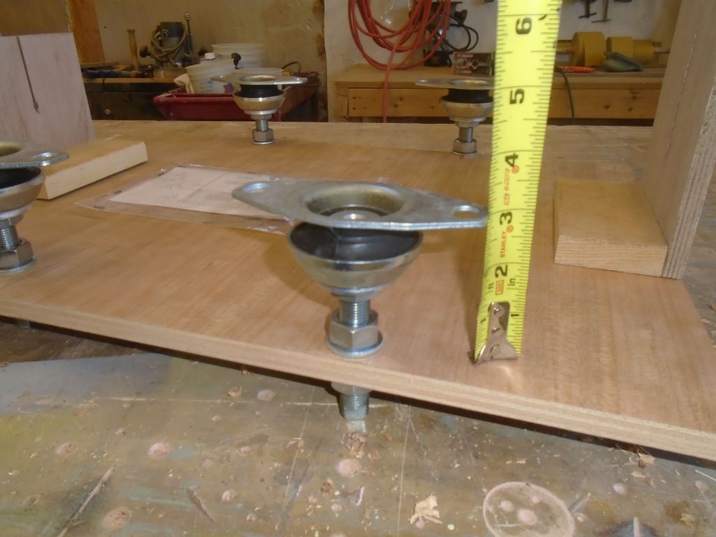
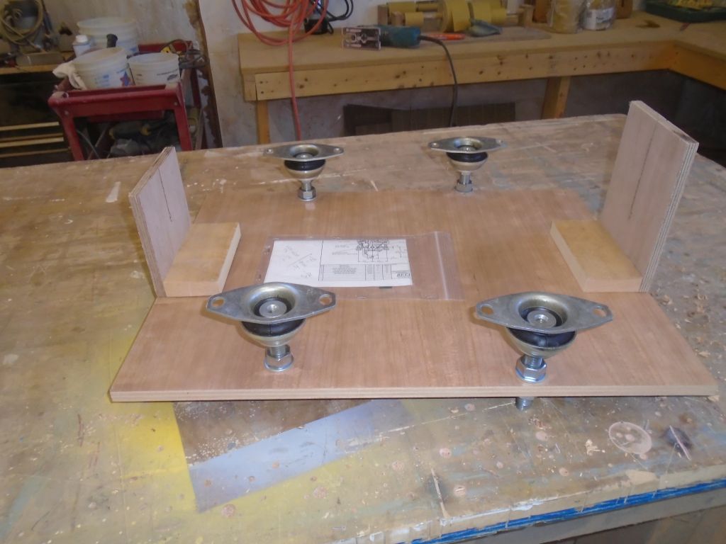
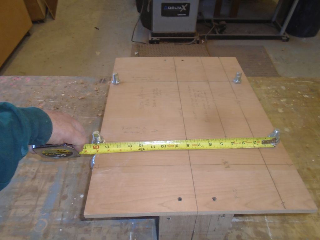
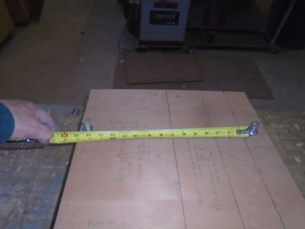
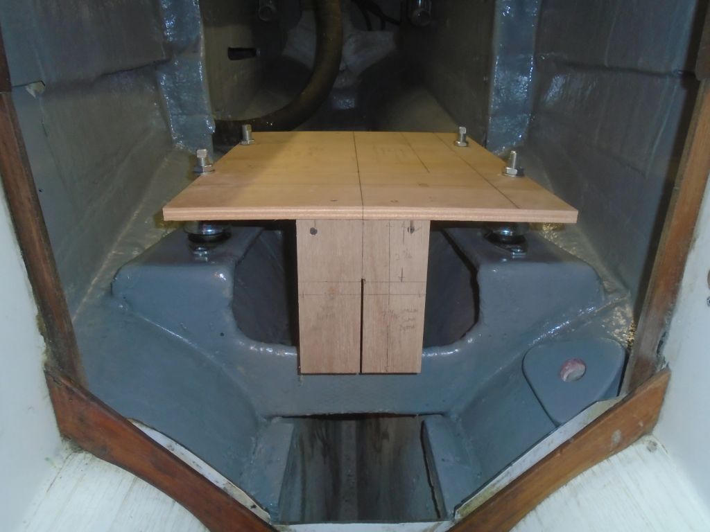
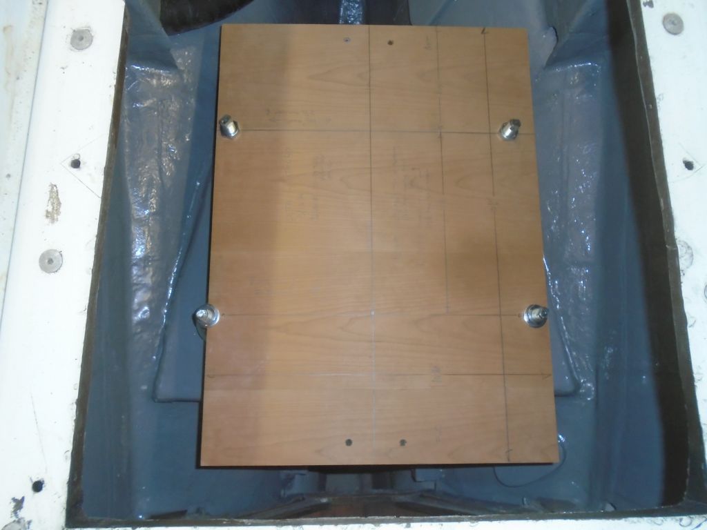
With an updated engine drawing, I prepared a plywood base that corresponded with the maximum length and width of the engine, and attached to its bottom an extension fore and aft, which mainly gave me the shaft centerline, which was the most critical dimension for proper alignment. At the aft end, I built the extension to correspond with the depth of the transmission housing; the forward extension corresponded to the depth of the oil pan (though not the location). This gave me all the maximum dimensions required to ensure that the engine would fit as expected. I also noted the overall height above the platform. I marked the engine mounting locations, using the drawing as a guide, and temporarily installed the adjustable mounts, starting with a 3″ depth, which was right in the middle of the mounts’ specified adjustment range. In this specific instance, I’d ordered the new engine with 14.5″ mounting centers at the aft side, and 16″ at the forward, as this would work best with the existing engine foundations. Because the “centerline” of the engine ( aka the shaft centerline) was actually not symmetrical with the overall dimensions, the starboard forward, at this wide dimension, was actually almost off the template completely, since the center of the mounting flange was wider than the overall width from engine center.

I quickly tested the new template in the boat to check the fit. It looked good overall, but I thought my initial adjustment on the mounts was probably too high (the shaft centerline was above where it needed to be), but I’d adjust those and finalize the template (and therefore engine) position a little later on. The template would be ready whenever I was.
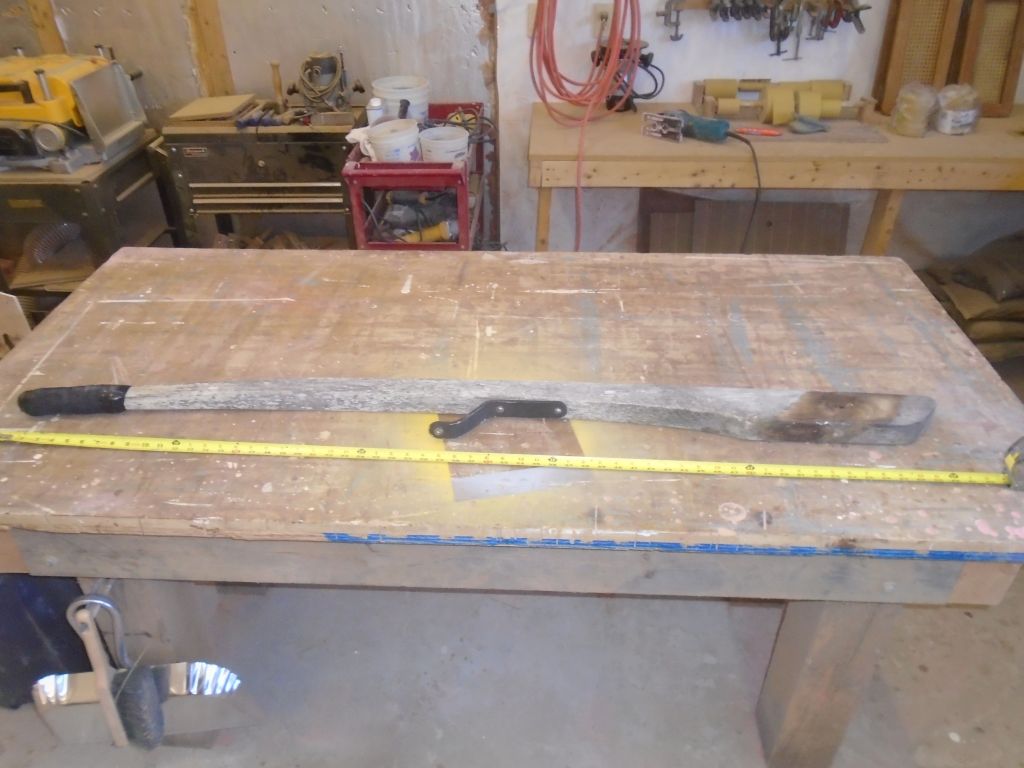
Next I turned to the tiller. The original tiller, made of solid wood, was in poor condition, and I was tasked with building a new one from laminated teak. To start, I removed an old autopilot mount and the friction tape wrapping from the tip end, leaving the bare tiller to use as a guide for laminating the new one.

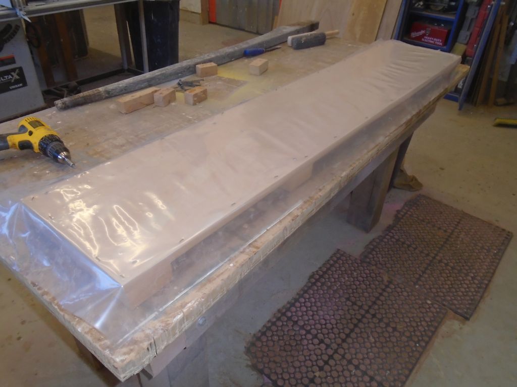
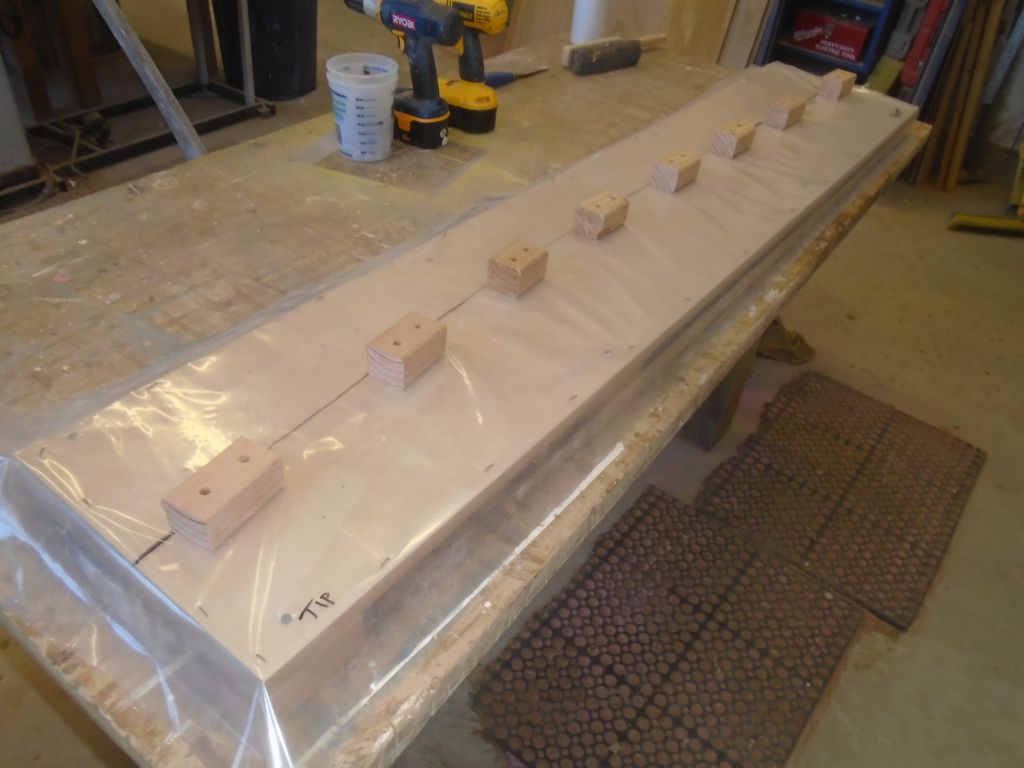
I dug out an old laminating template that I’d used on some project or another in the past, and removed the old blocking and plastic left over from that job. With a clean, flat template re-covered in plastic sheeting, I used the tiller to mark the curvature on the plastic, then installed clamping blocks as needed against the line–enough blocking to bend the wood strips into the fair curve required, and to provide ample clamping area. I like laminating templates built on the horizontal like this (as opposed to a vertical orientation, where the laminations are clamped on top of a form that is open on both sides) since it makes aligning the strips with one another (i.e. flush) much easier, since one can press and (if needed) clamp the whole assembly to the flat base, which ensures that the lower (template) side of the lamination will be flat and smooth. Epoxy-coated laminations are extremely slippery, and the flat base means that one need not be fighting alignment through the clamping process. The end result also makes shaping and dimensioning the finished piece that much easier since there’s a flat and consistent side from which to start, and it’s quick and simple to build the template.


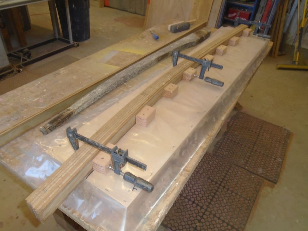
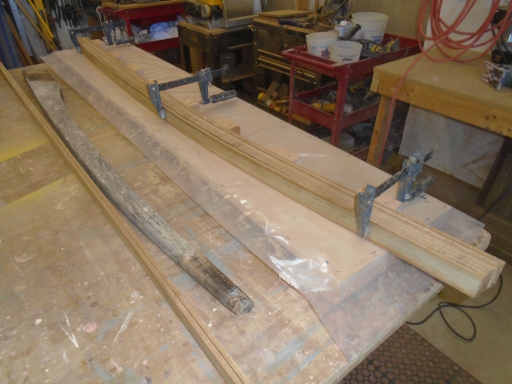
From some leftover teak on hand, I milled a series of 1/4″ thick strips, each a bit over 1-3/4″ wide (the raw dimension of the rough stock), from which to laminate the new tiller. The finished piece needed to be about 1-5/8″ thick. These strips bent easily to the minimal curvature required.
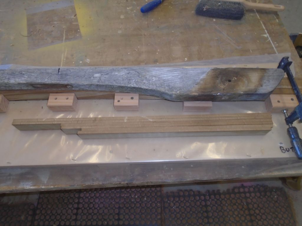
The tiller was fairly consistent and relatively narrow over much of its length, but the butt end flared quickly into a depth almost twice that of the rest of the tiller. Gluing the whole blank to that dimension would be wasteful of material, and more difficult to glue all at once, so with enough strips to complete the tiller other than the butt end, I cut some additional strips into shorter lengths, and these would become the deeper butt end later. I’d glue up the main blank first, then add on these strips at the end afterwards.
The template would require a little more prep work, mainly some bits of plastic to prevent the blank from sticking to the template blocks, and as tempting as it was to continue and glue up the blank, I was running short on time and would continue sometime later.
Total time billed on this job today: 2.75 hours
0600 Weather Report:
50°, clear. Forecast for the day: sunny, high 60°