

March 22, 2016
Salty 23
Tuesday
Before I could truly finalize the Monitor installation, I needed to properly prepare various fastener holes for the mounting brackets, which meant disassembling everything; I couldn’t complete the diagonal braces (which would run between the bottom of the Monitor frame and the upper support tubes) till I could properly and permanently install the main support tubes.
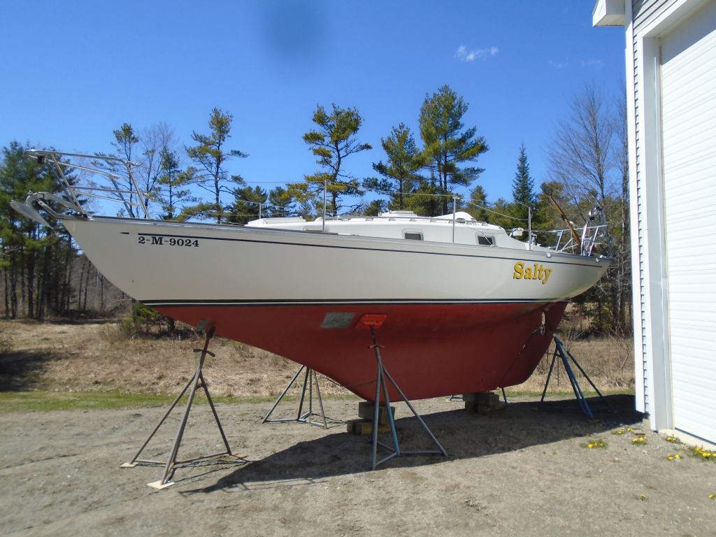
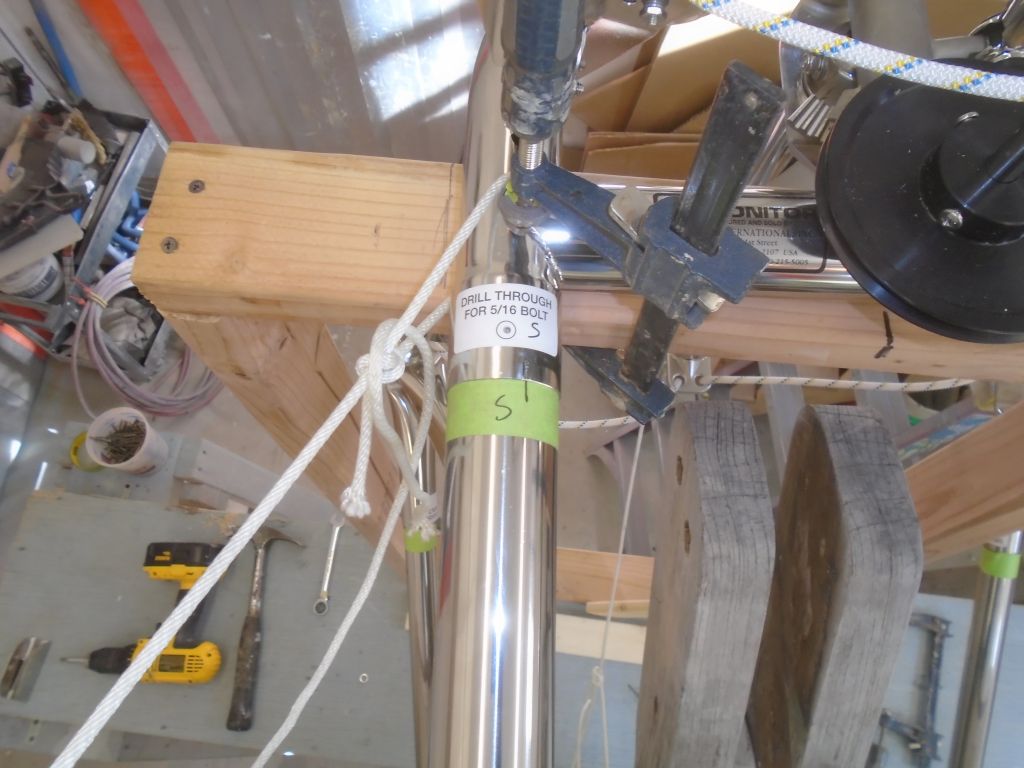
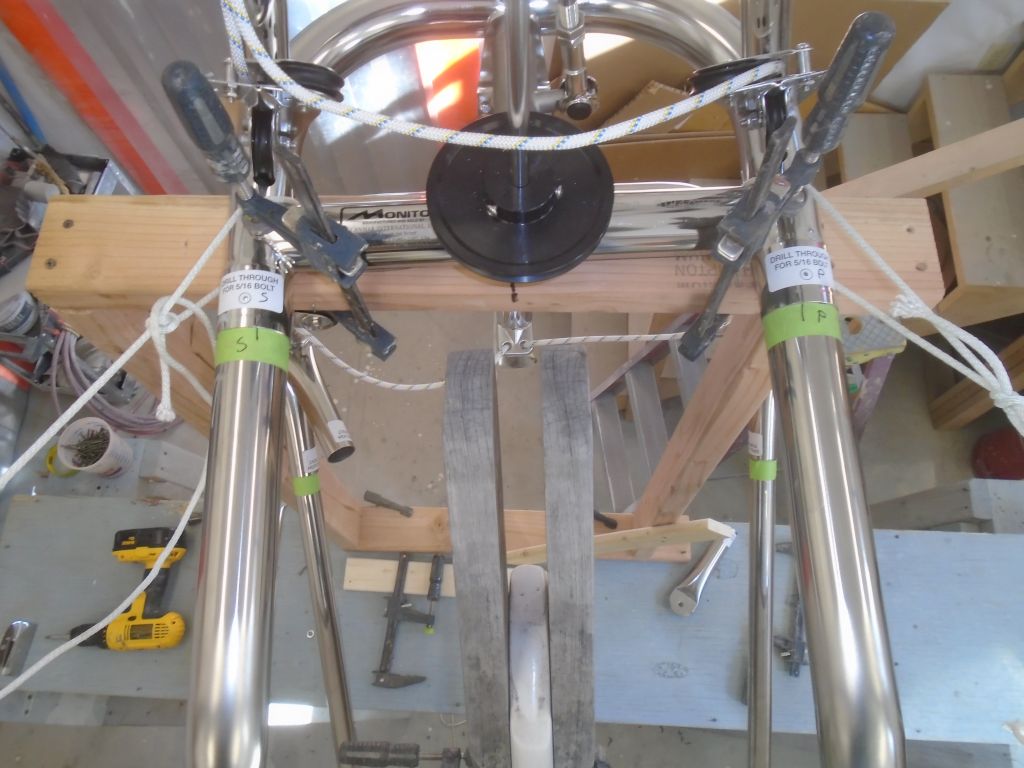
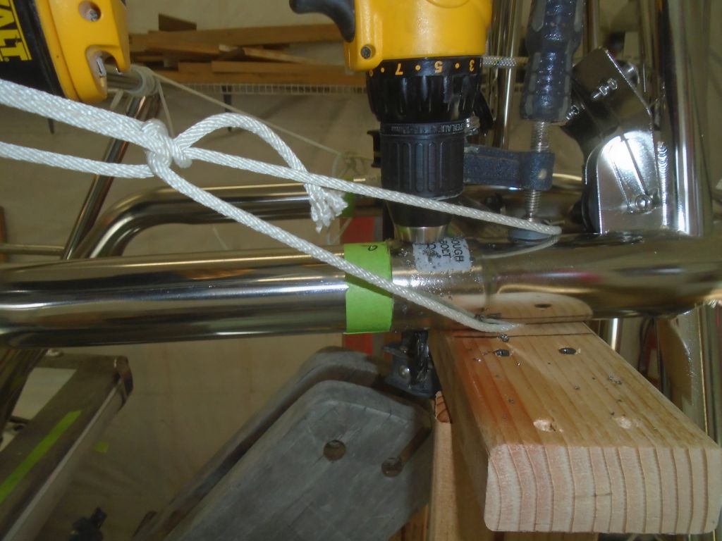
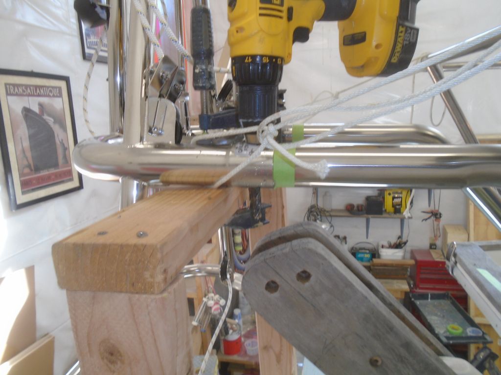
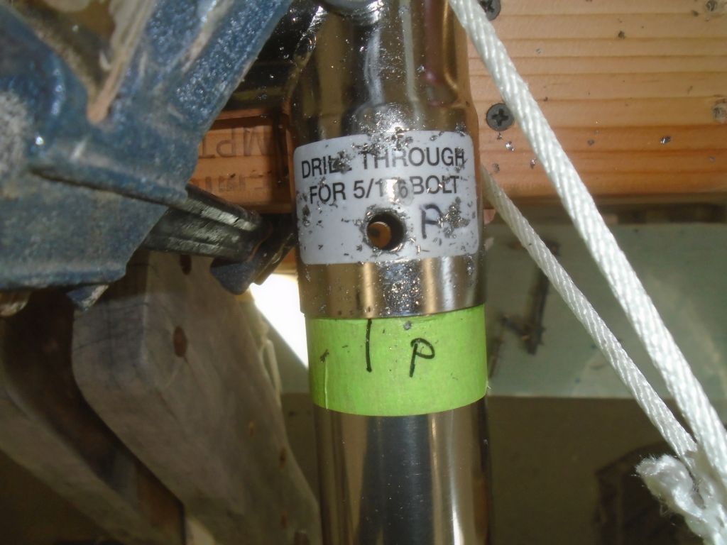
But before going down that road, there were a few more things I could and should do first, starting with drilling holes through the main support members at the windvane frame itself, in two pre-marked (at the factory) locations. This would ultimately pin the upper support tubes to the frame. All the frame and support members would eventually be pinned like this, and I’d do the remaining drilling and pinning later, but this set was the most critical, and the upper tubes weren’t going to change their position at all, nor did I want them to, and I also had to install inserts within the tubes that would prevent compression when the tubes were bolted together though the new holes. So while the upper tubes were in this position, I drilled through the two required locations with a 5/16″ bit.

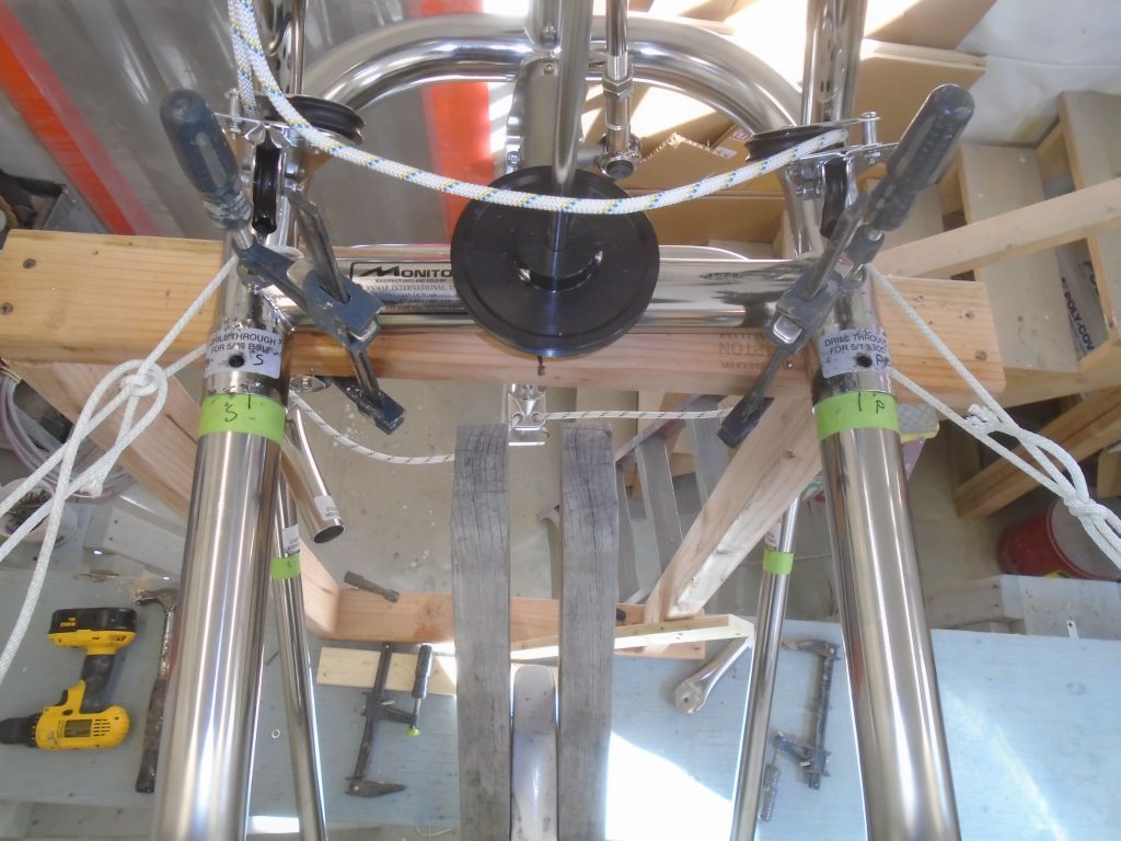

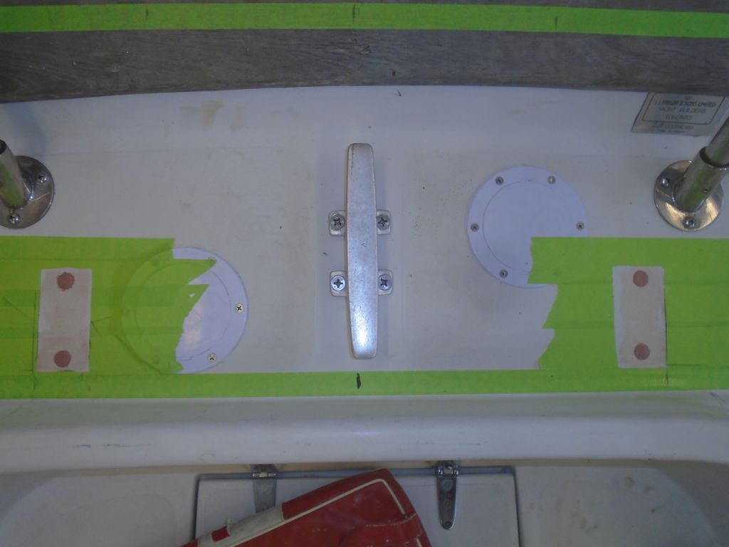
The locations of the upper brace brackets were already marked on the masking tape on deck, as were the lower brace brackets, So now, I could remove the support tubes so I could finalize the hull and deck bracket installations. With the windvane frame supported by and secured to the wooden framework I’d built, I removed all the support tubes as needed, then unbolted the brackets and made final hole preparations by boring out the locations with a 5/8″ bit to remove any core. I found that the two forward holes on the deck brackets were actually in an area of solid fiberglass, just forward of the transition to the plywood core, so as it turned out I’d not needed to overbore those two holes, but who knew.

The upper set of holes on the transom brackets were in a section of the transom cored with plywood; I knew this because I could see the outline of it from inside. The lower holes were in solid fiberglass, but with the upper holes properly marked based on the bracket position, I overbored the holes to remove the core from the upper locations.
Preparations complete, I filled the new voids with thickened epoxy, leaving it to cure overnight, after which I’d be able to complete the installation.
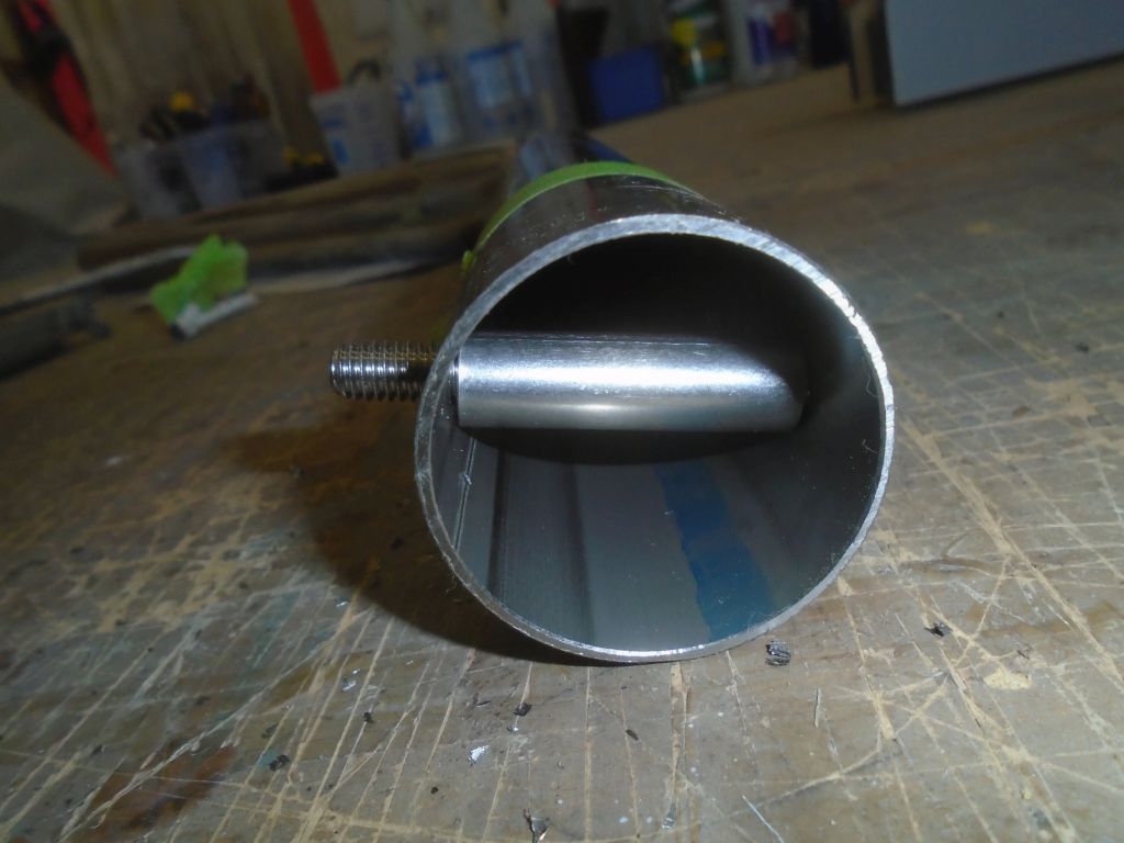
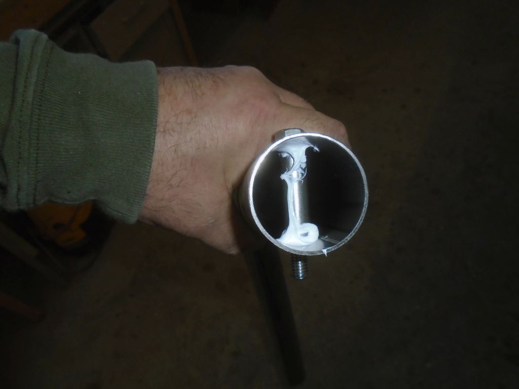
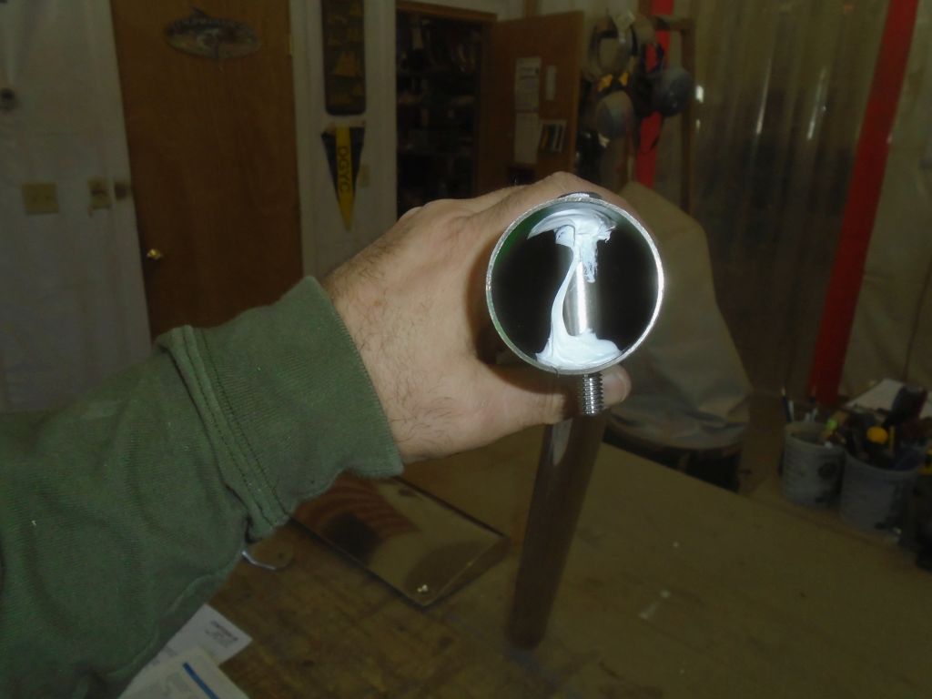
Down on the bench, I installed the stainless steel inserts in the two main support tubes, using some sealant to hold them in place. I kept them aligned by running through the bolts that I’d eventually use to secure the frame and tubes. I set them aside for now. I’d have to repeat this process with other frame support members later.
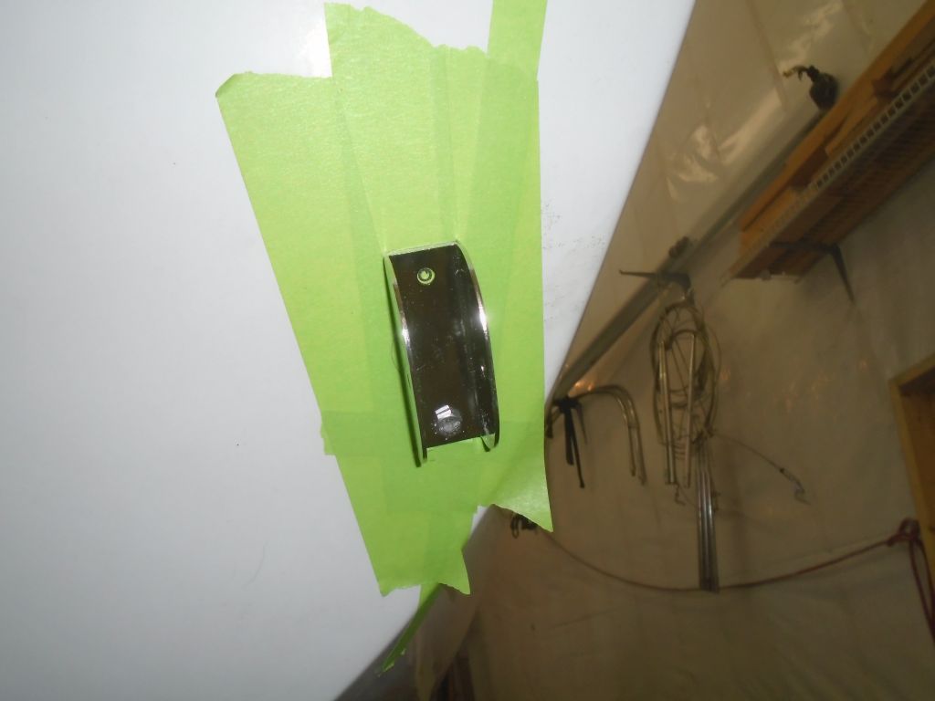
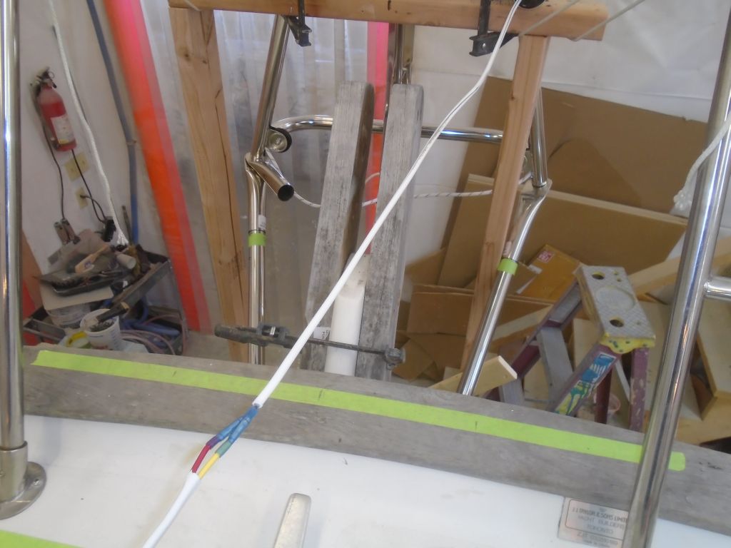
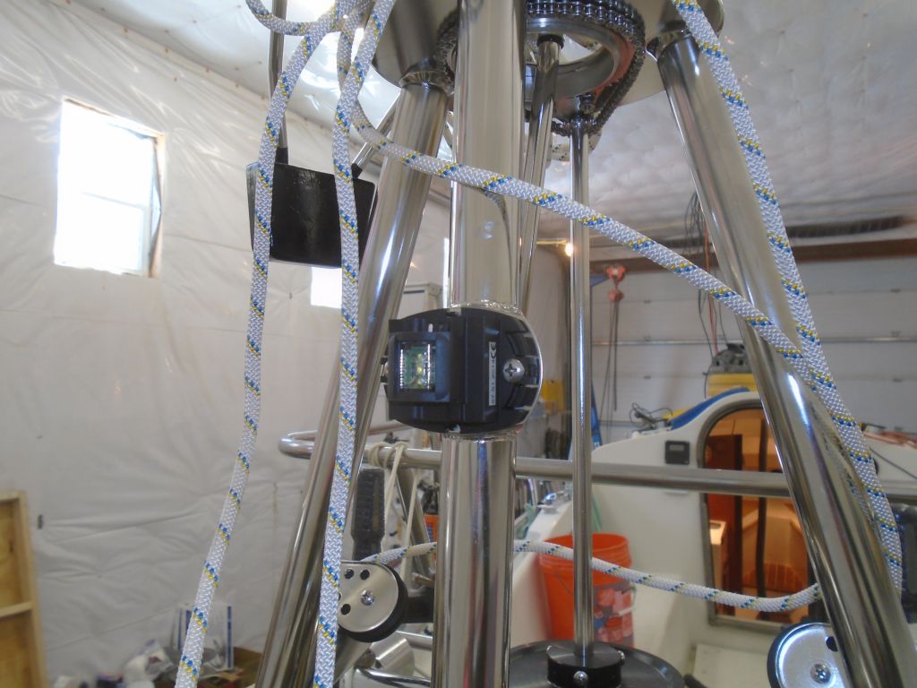
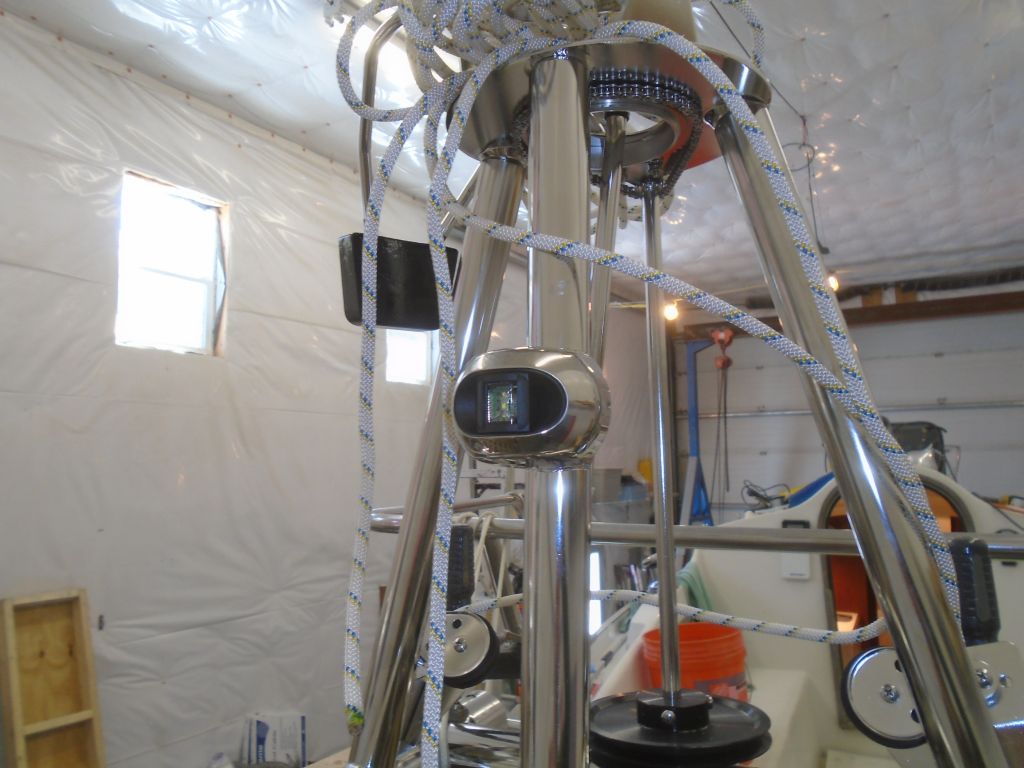
This windvane came with an LED sternlight built into the upper part of the frame, and the light was wired through one of the upper supports. With the extra-long upper support tube on this boat, the wire length supplied from the factory (which would have been adequate for most installations) was not long enough to extend all the way through the tube, so while things were disconnected I added a wire extension that I could run through the whole tube during final installation. Then, secured the light fixture to its welded bracket (it had been shipped pre-wired, but not bolted in plate, presumably to prevent damage during shipment). The light came with a little stainless steel cover that I snapped on afterwards.
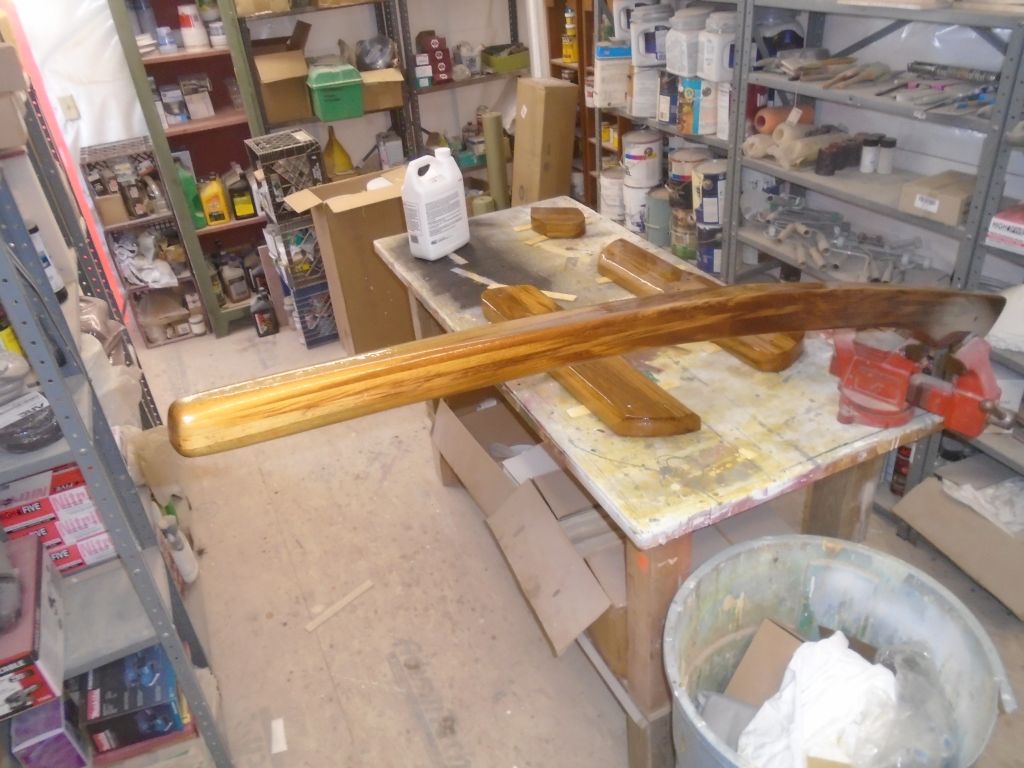
That was it for the Monitor for the moment, and I wrapped up the morning with a new coat of varnish on the tiller and rudder cheeks.

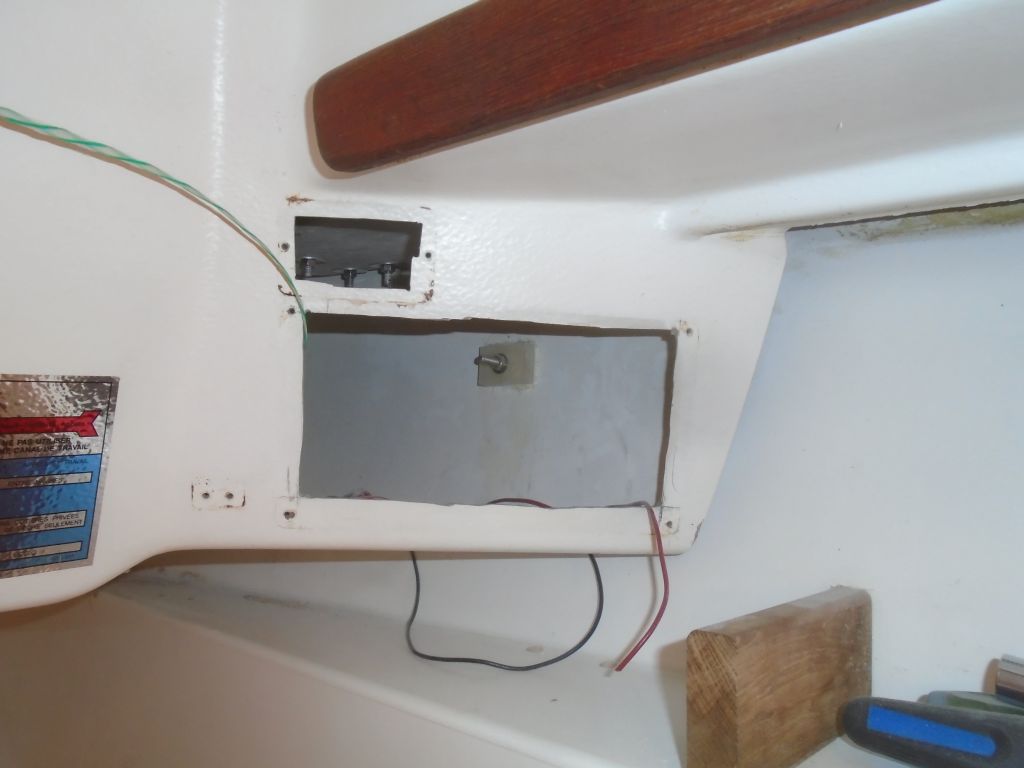
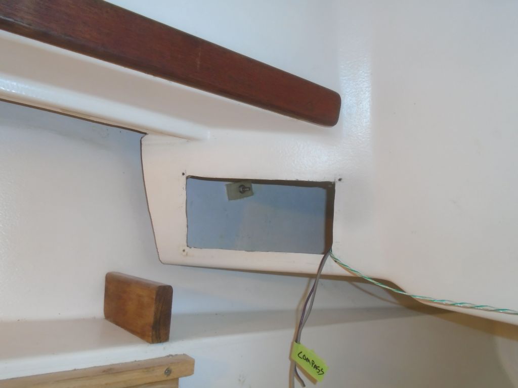
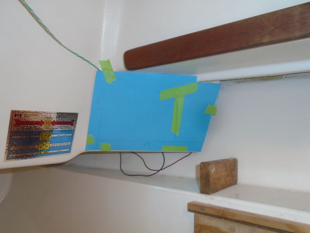
The owner asked me to build an enclosed locker above the port settee for various electronics mounting, and through various discussions we’d arrived at a raw concept. Before beginning to lay out the ideas in a mockup, I wanted to see how the new electrical service panels were going to fit in the two locations at the aft end of the cabin, where the originals had been located, since the panel layout might affect certain aspects of the electronics locker.
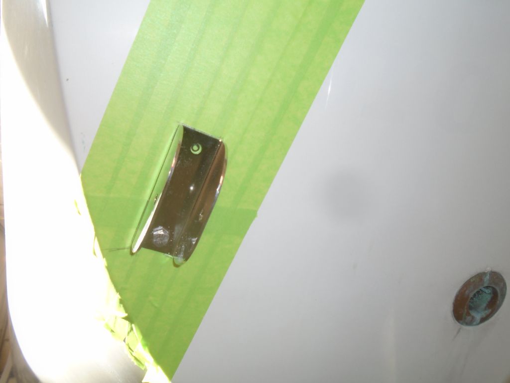
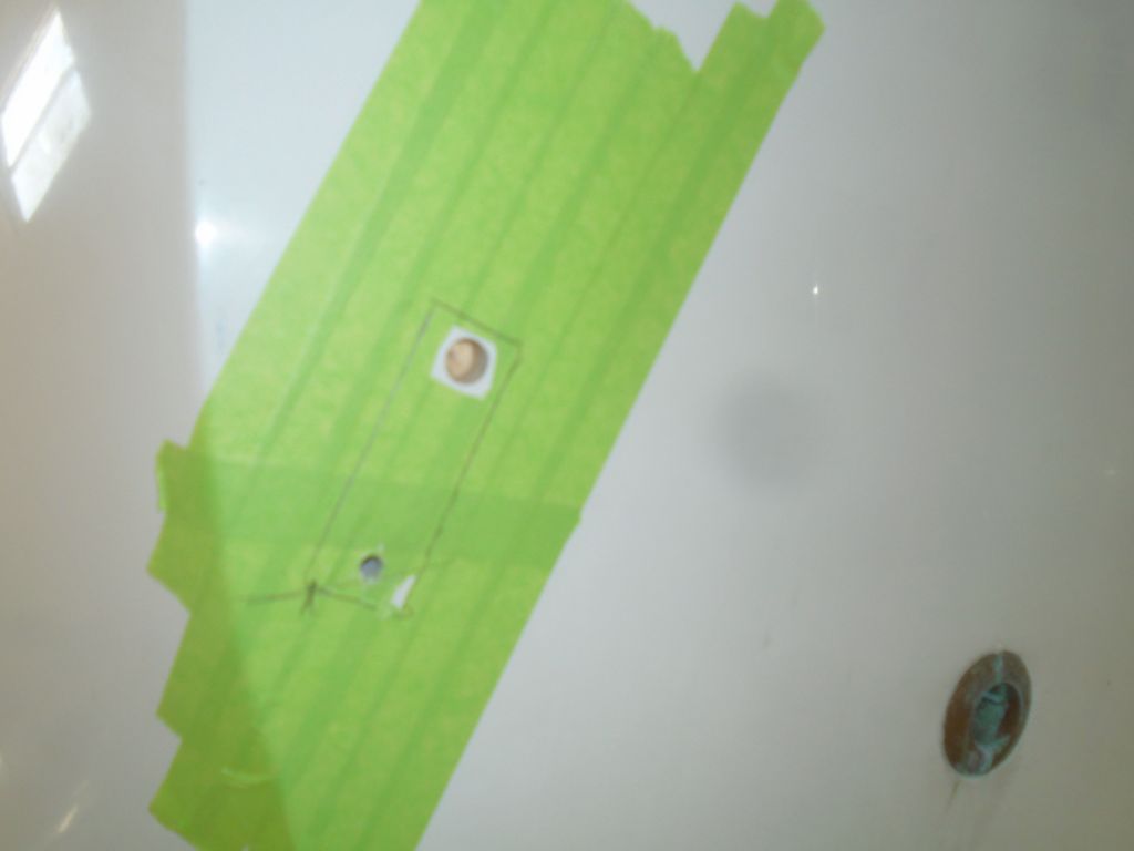
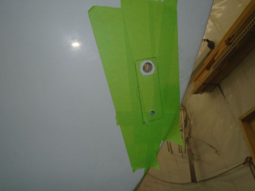
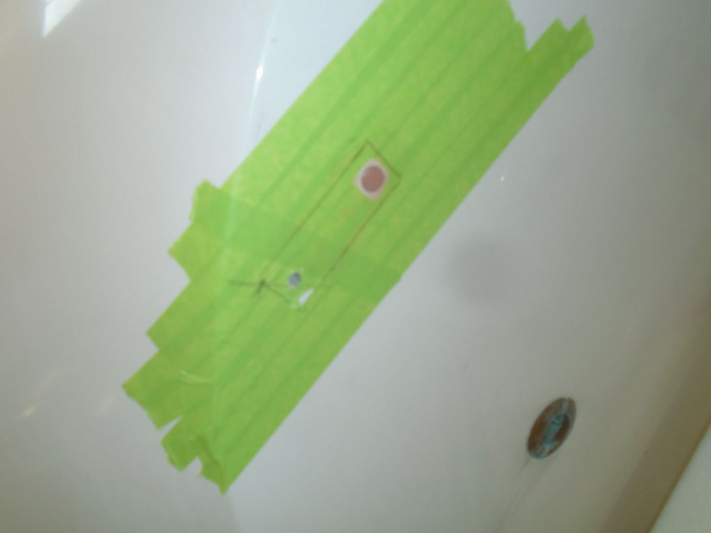
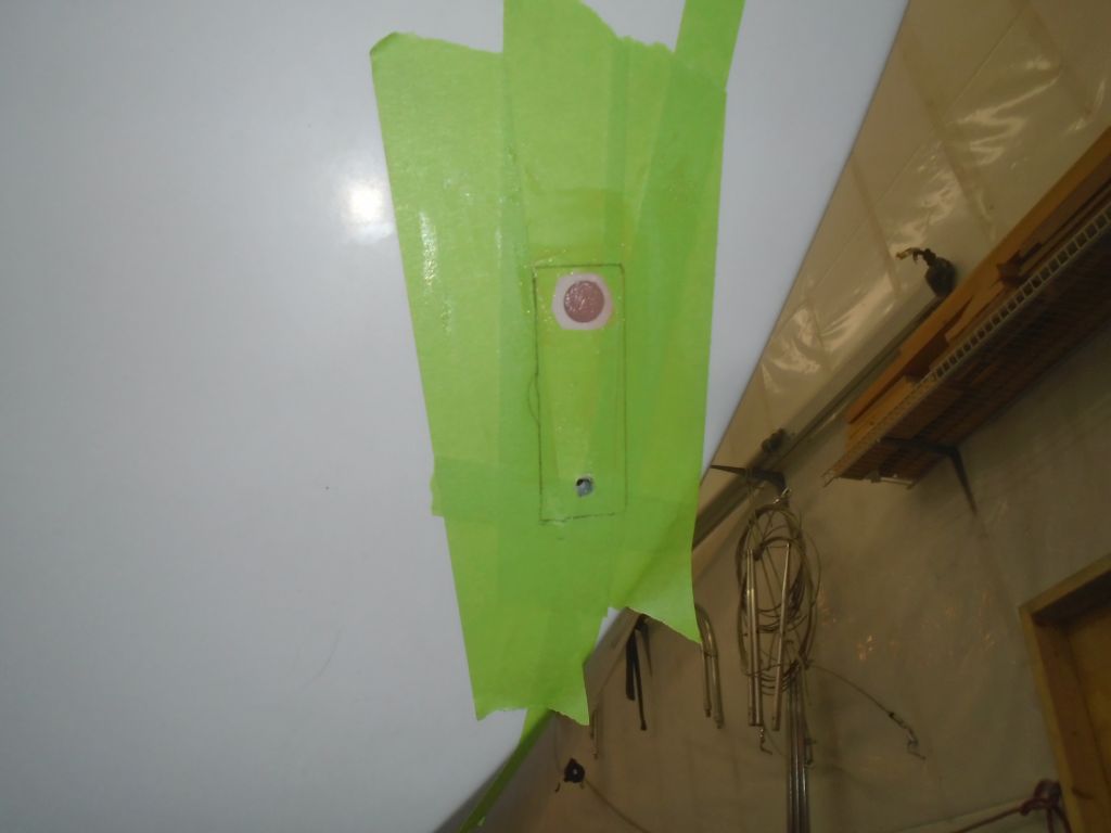
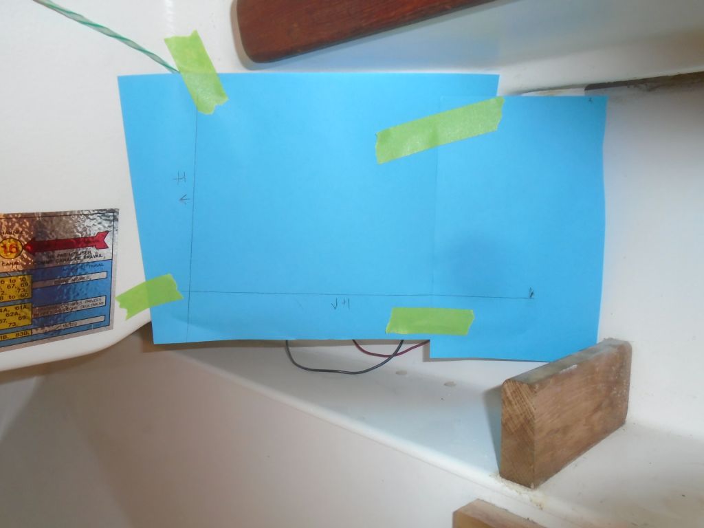
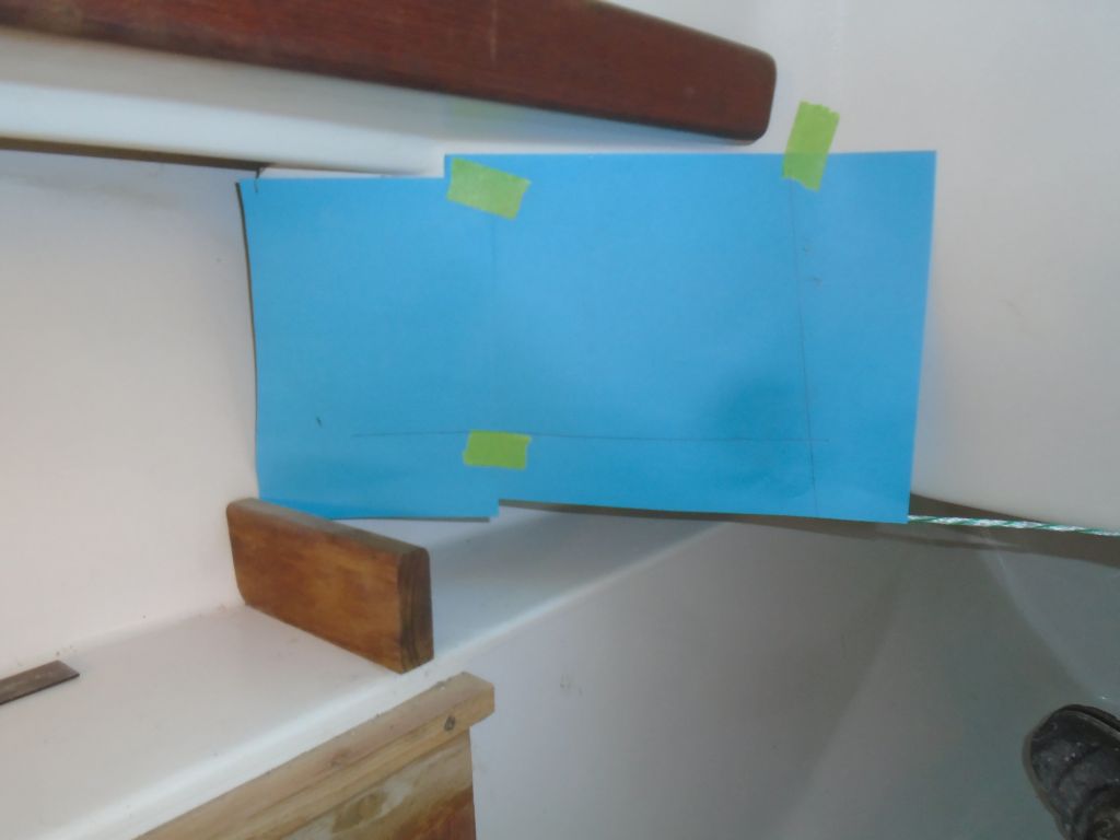
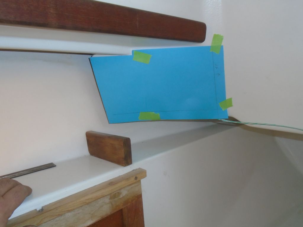
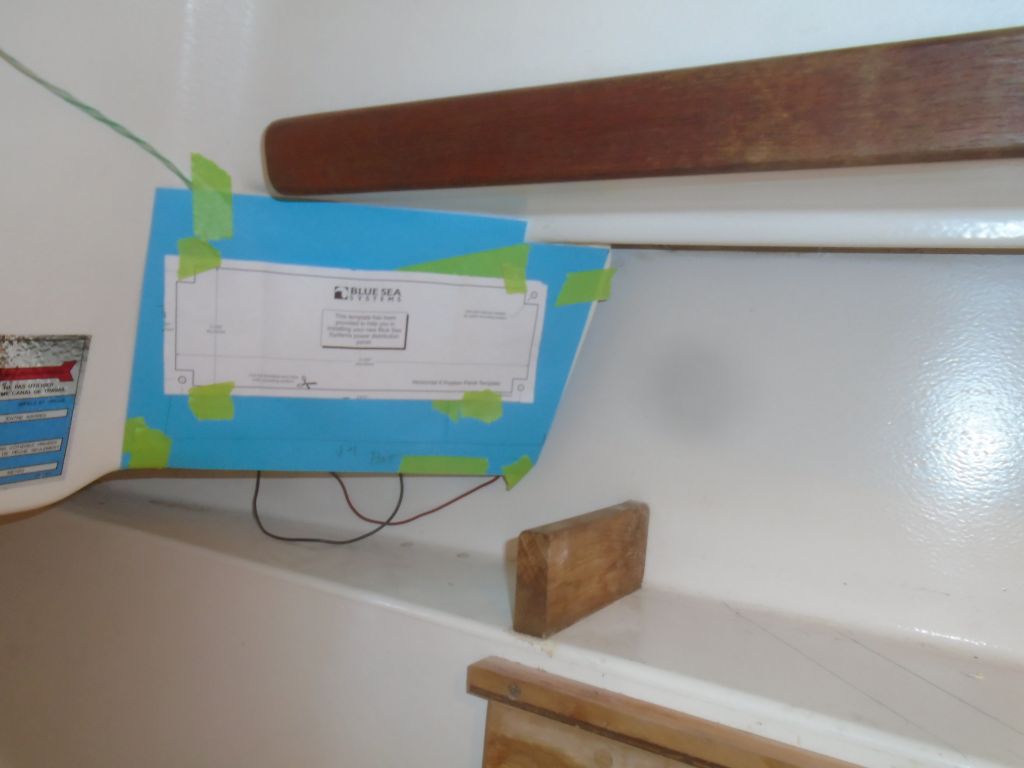
The new panels–one per side–were slimmer than the originals, and so to cover the old holes I’d need to build some covers for the original surface. I made simple patterns of each side (of course they weren’t symmetrical from side to side), which I’d use later to make veneer panels. Then, on the port side, I taped in a representation of the panel’s outside dimensions so that I could see how, or if, it affected any decisions we might make about the electronics locker.
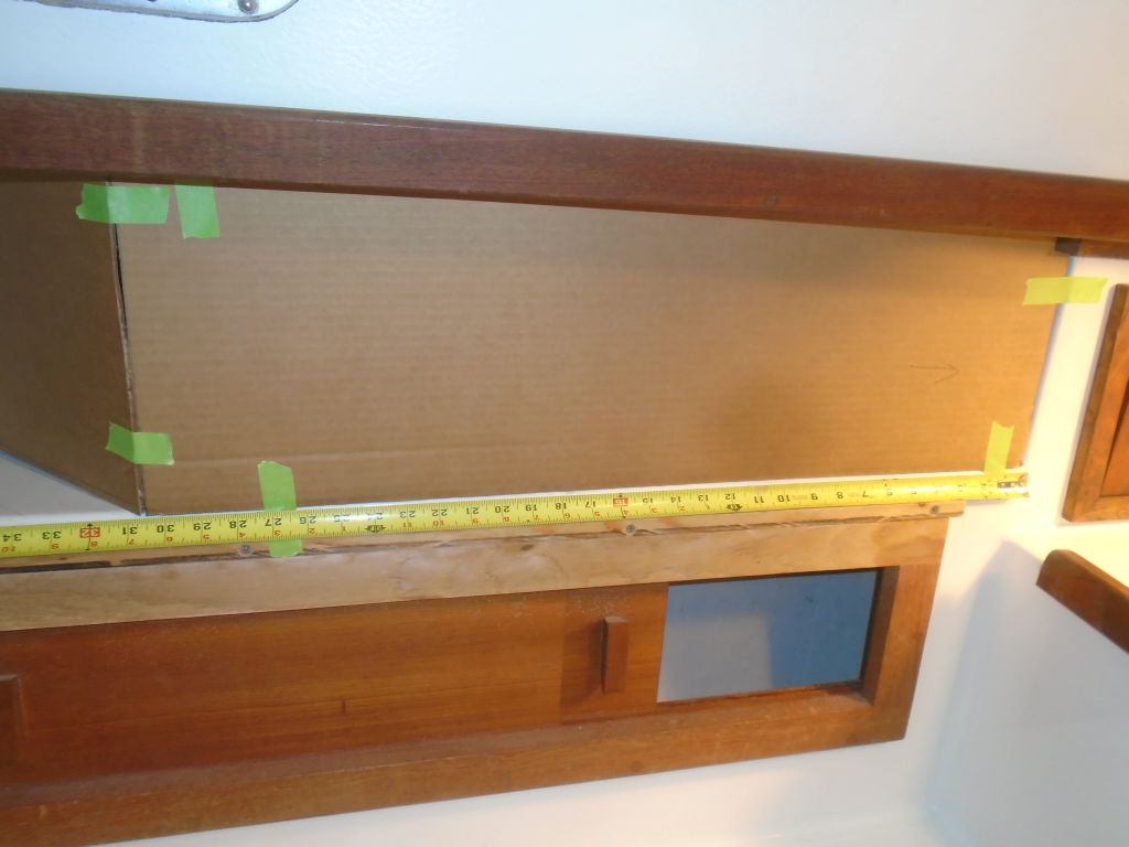
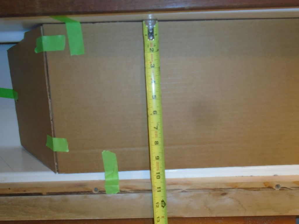
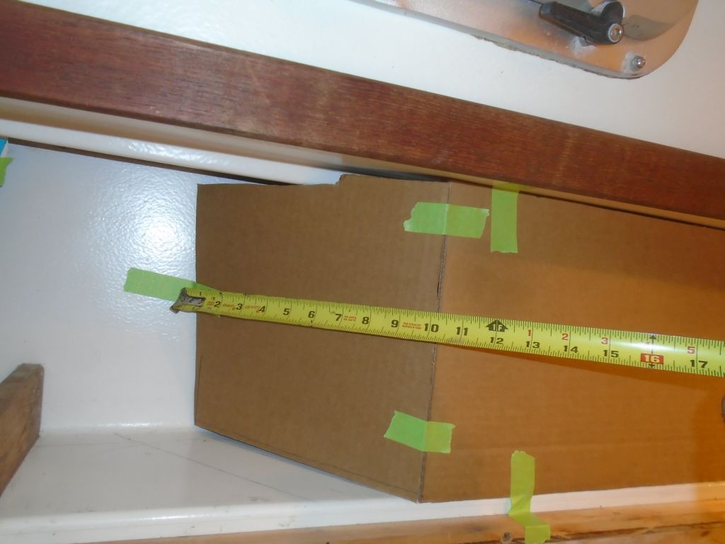
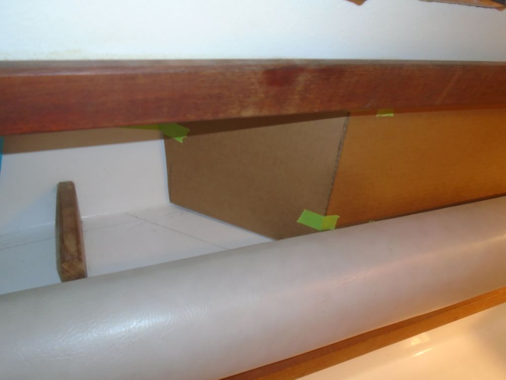
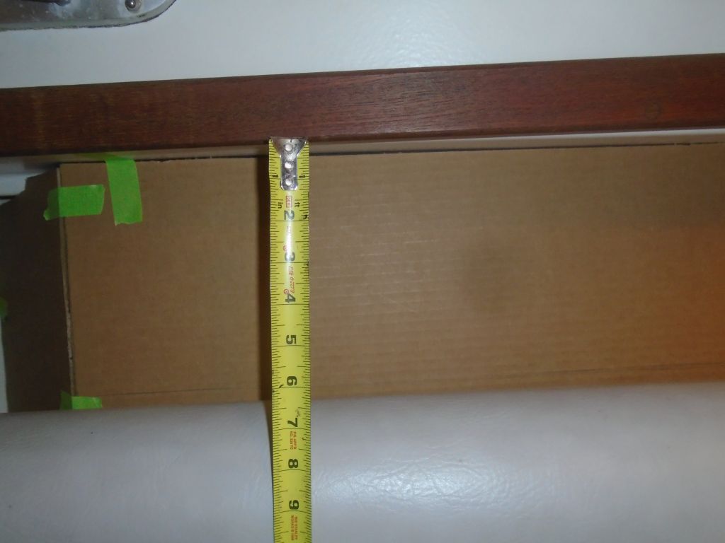
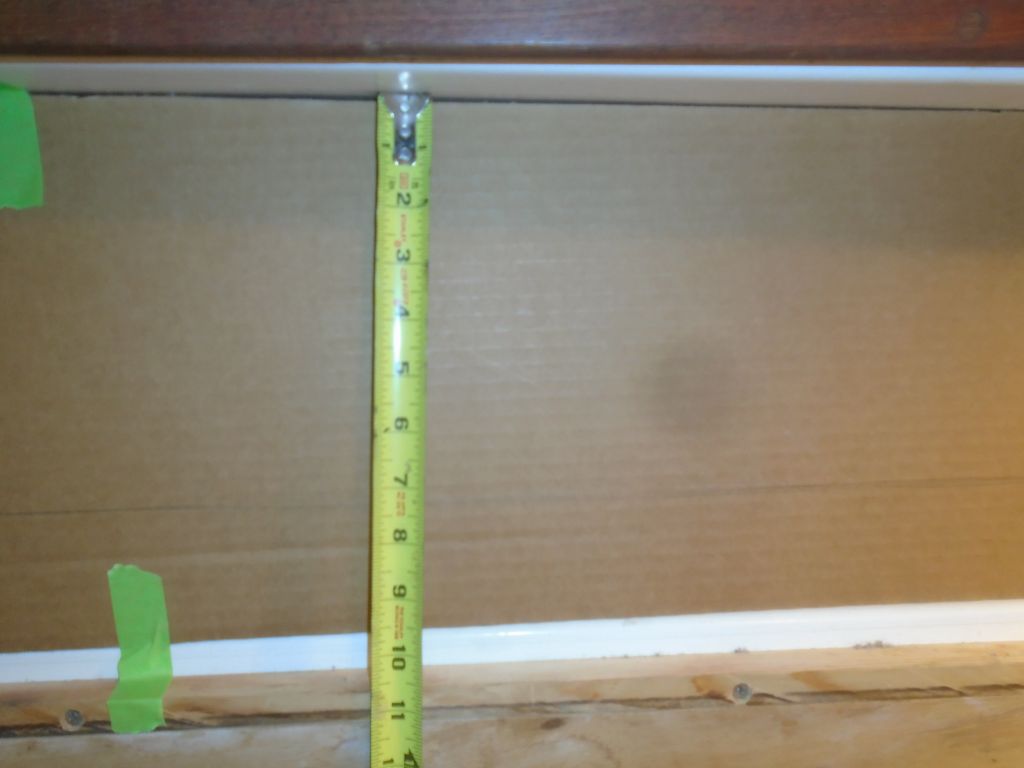
The rough idea for the new locker was to mirror the angle of the electrical panel at the aft side, leaving a little nook for securing and charging the usual small devices of today, then extending forward to the galley with a flat panel suitable for flush-mounting things like a VHF radio, stereo, and other things. So I measured the angle and reproduced it on the forward side of that little wooden fiddle, choosing a more or less arbitrary starting point by eye, to leave some space between the fiddle and the new panel for storage of small items. From there, it was a pretty simple matter to cut some cardboard into the rough shapes required to produce a 3D representation of at least the first run at the new locker.


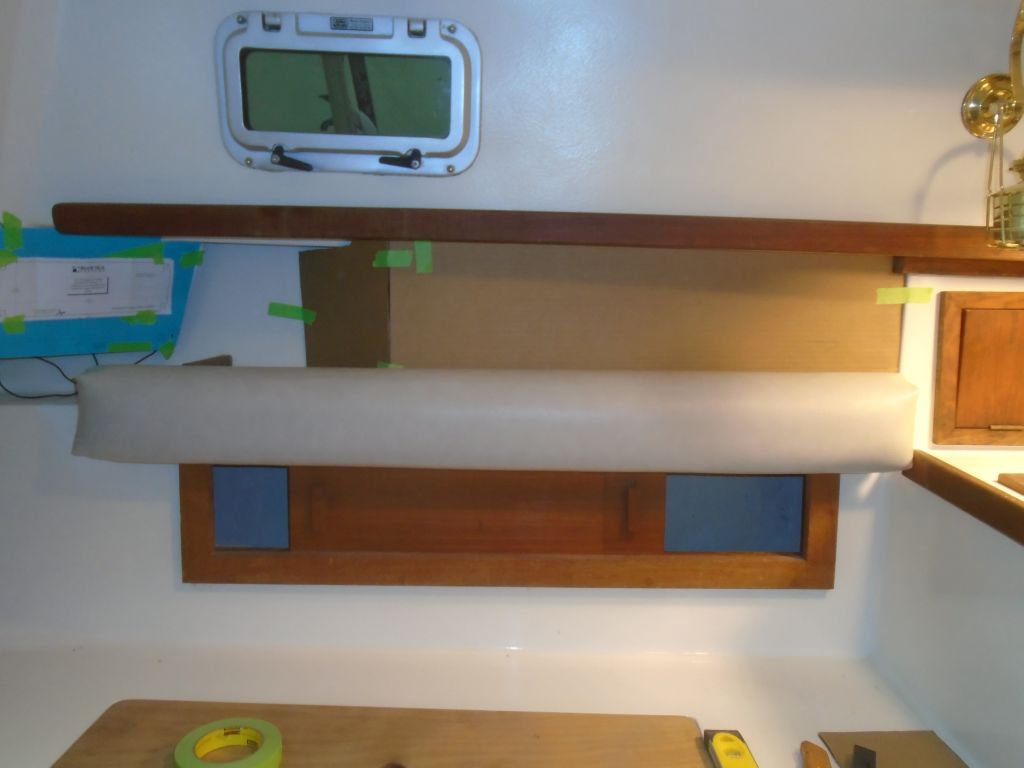
The backrest was going to have an impact on the amount of usable space on the new locker panel, and would also enclose securely the little shelf at the aft end, so I placed it in position to determine how it affected things. It did create a very nice, cozy area to place a camera, phone, or other handheld device, but effectively reduced the height of the flat panel by a few inches. For now, I didn’t try to construct a panel that might span between the electrical panel on the left (aft) and the new angled panel on the right (forward), but the angles involved would make it tricky to shape, and the overall size of the new electrical panel on the aft angle meant that any depth available behind such a connector would be pretty minimum, perhaps an inch or so, in order to clear the panel.
With these basics in place, we had something to work with, and I could make changes as needed from here based on the owner’s feedback.
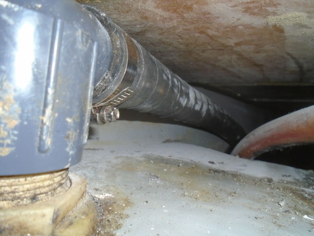
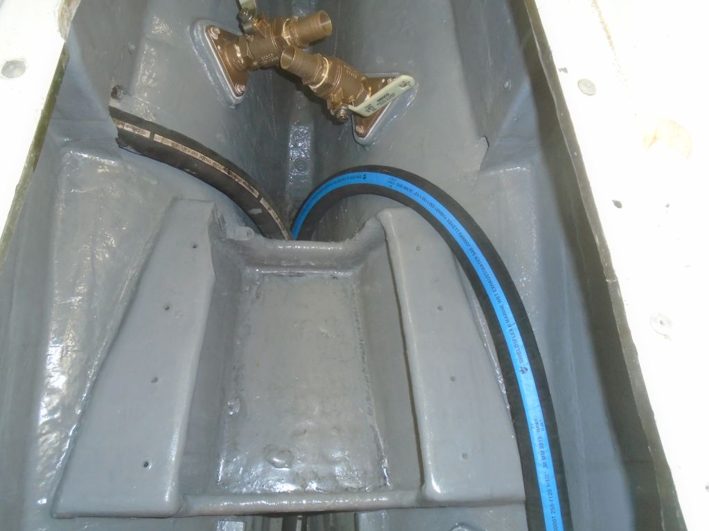
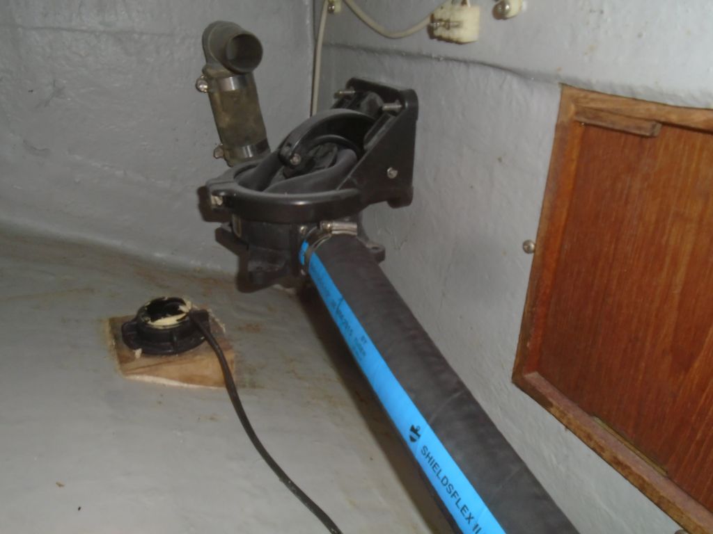
Now I moved on to several smaller jobs, starting with replacing a round access panel into the holding tank beneath the cabin sole. The existing deck plate was missing its screw-in cover–no one knew where it was–so I bought a new one, Of course the cover from the new deck plate was a slightly different size from the existing ring, so I had to remove the whole ring and replace it with the new one. One should never expect the easiest way to actually work. Meanwhile, I reconnected the waste tank pumpout hose, which led aft through the engine room and up to a deck plate.

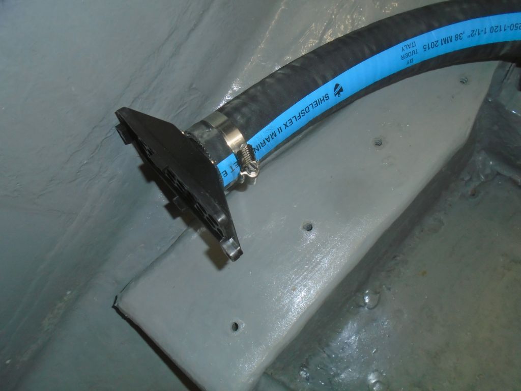
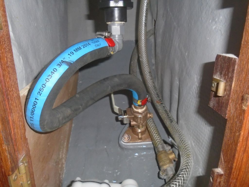
With new hose freshly on hand, I began to replumb the cabin-mounted bilge pump, and started with its new suction line, which ran through the engine room on the port side and down into the sump beneath. I installed a filter on the bottom of the hose and led the end forward, where I reconnected it to the existing pump. I thought it best to run these lines now, while I still had the best engine room access, rather than fight them around the engine later. I’d planned and expected to continue with the discharge line, which would run back aft to the new through hull valve, but the lengths of hose I’d planned to use, and which I’d previously determined I had on hand (and thought was adequate) turned out to be a little too short to make the run, so I had to order a longer length, delaying the completion of this pump’s plumbing for a bit. I also planned to work on the new cockpit-mounted pump in the immediate future.
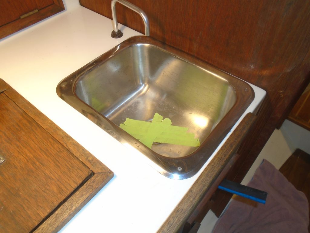
Continuing with the sort of stream-of-consciousness knock-off-the-list jobs that seemed to be making up my afternoon, I reinstalled the galley sink in new sealant, and installed a new drain hose to the new through hull.
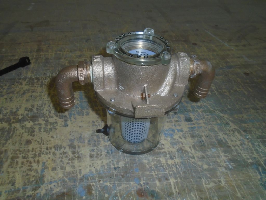
Thinking ahead to some of the engine’s ancillary systems, and looking to fill a final void in the day, I prepared the new raw water strainer for installation by securing two 90° pipe elbows to the housing, ready for hose connection.
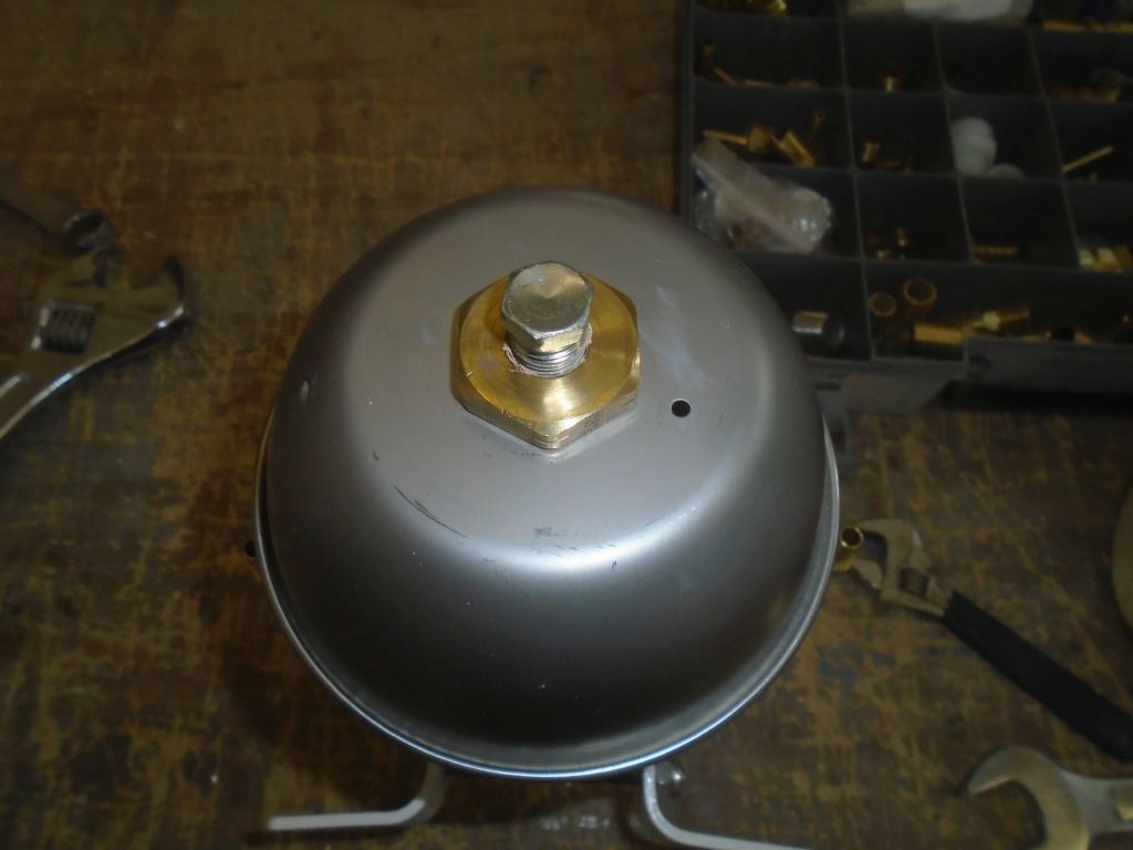
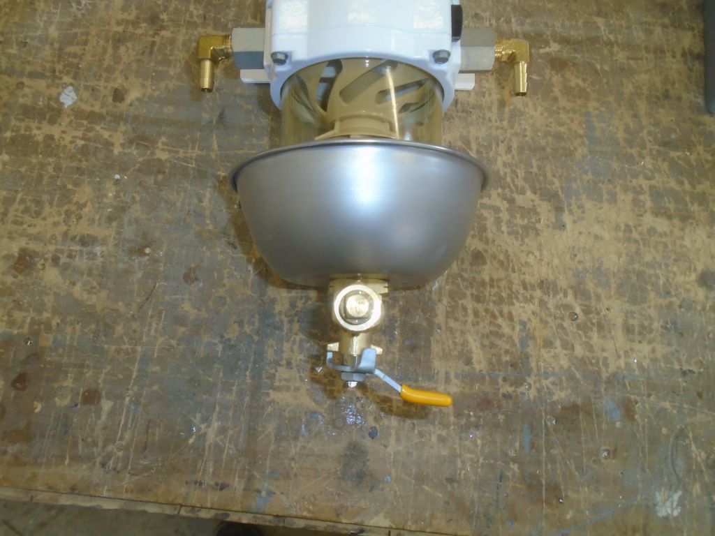
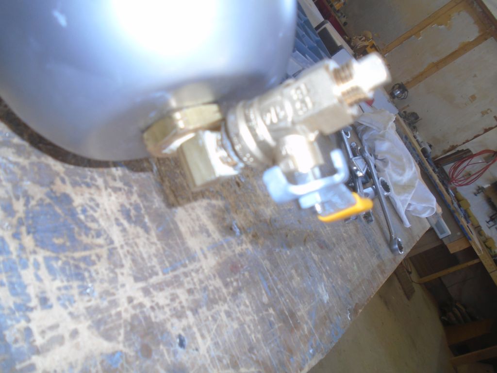
Finally, I prepared the new fuel filter for installation, first by installing the special and required adapter fittings into the filter housing, then a pair of 5/16″ brass elbows for the fuel hose.

To make maintenance easier, particularly in tight spaces, I liked to add a valve to the drain fitting on the filter bowl. In this case, with limited headroom, I planned to mount the filter as low as possible, to leave room for cartridge replacement from above, so I installed the drain valve on a 90° elbow off the bottom of the bowl, replacing the original drain plug.
Total time billed on this job today: 7.5 hours
0600 Weather Observation:
20°, clear, 6-8″ new snow from yesterday. Forecast for the day: Sunny, high around 40.