

March 24, 2016
Salty 25
Thursday
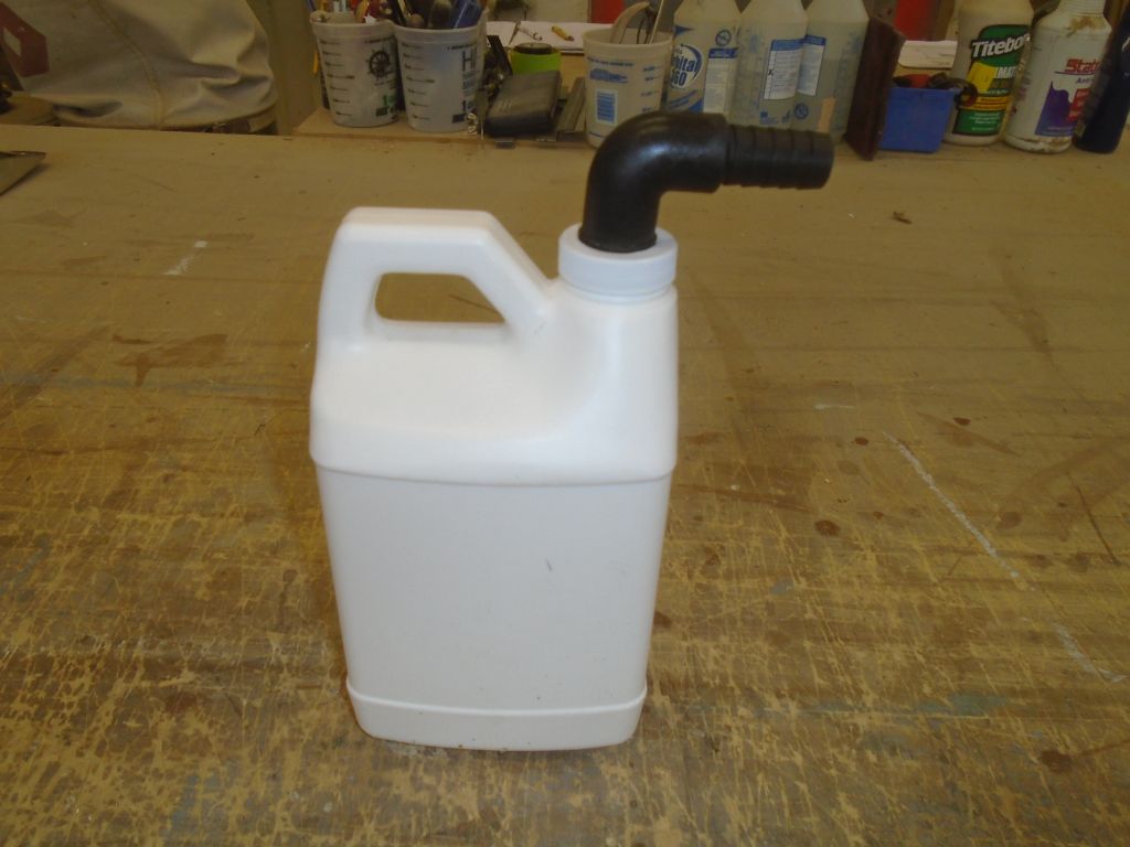
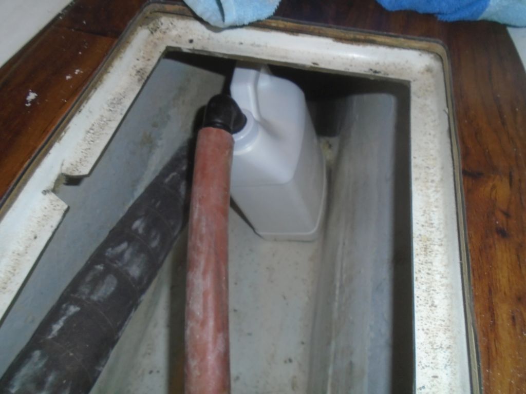
The built-in icebox had been draining into the bilge, which the owner didn’t like, and he suggested adding a small container in the bilge, into which the icebox could drain naturally; the jug could be easily emptied as needed. To this end, I chose a container size that would fit easily in the storage area beneath the cabin sole and be easy to maneuver, and added a hose fitting to the cap to connect the icebox hose. I’d add a simple means of securing the jug later, but I’d need to glue in some anchor points.
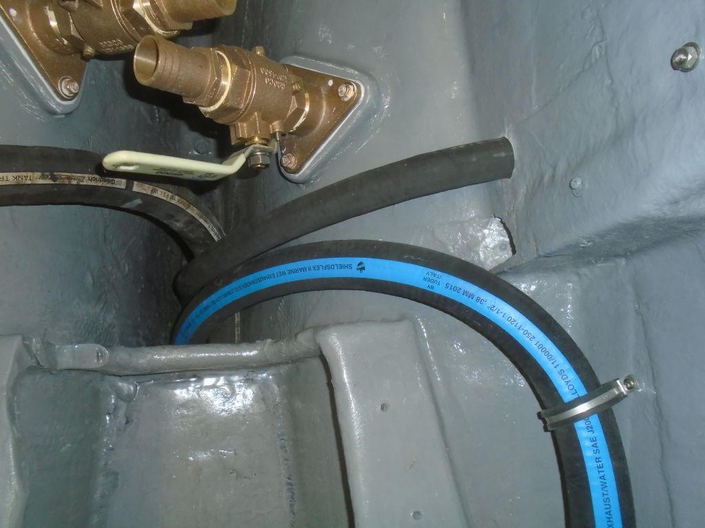
In the engine room, I added a support clamp for the bilge pump hose, to hold the hose clear of the engine beds, and also secured the waste tank hose beneath the engine pan so it didn’t droop down into the sump.
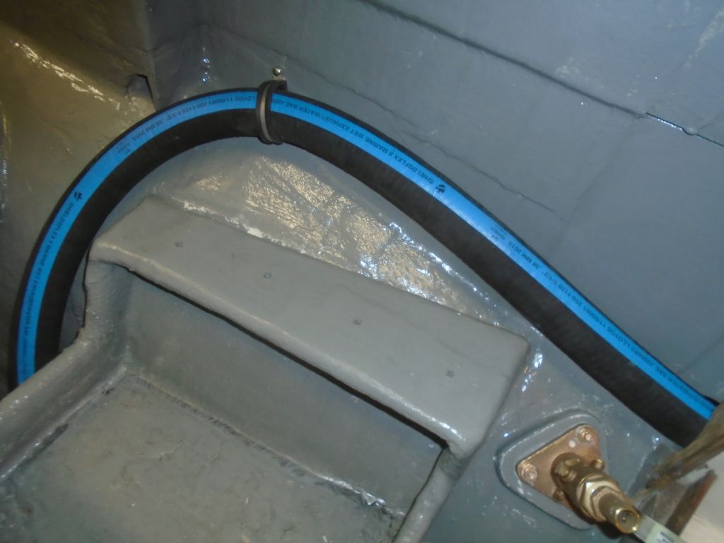

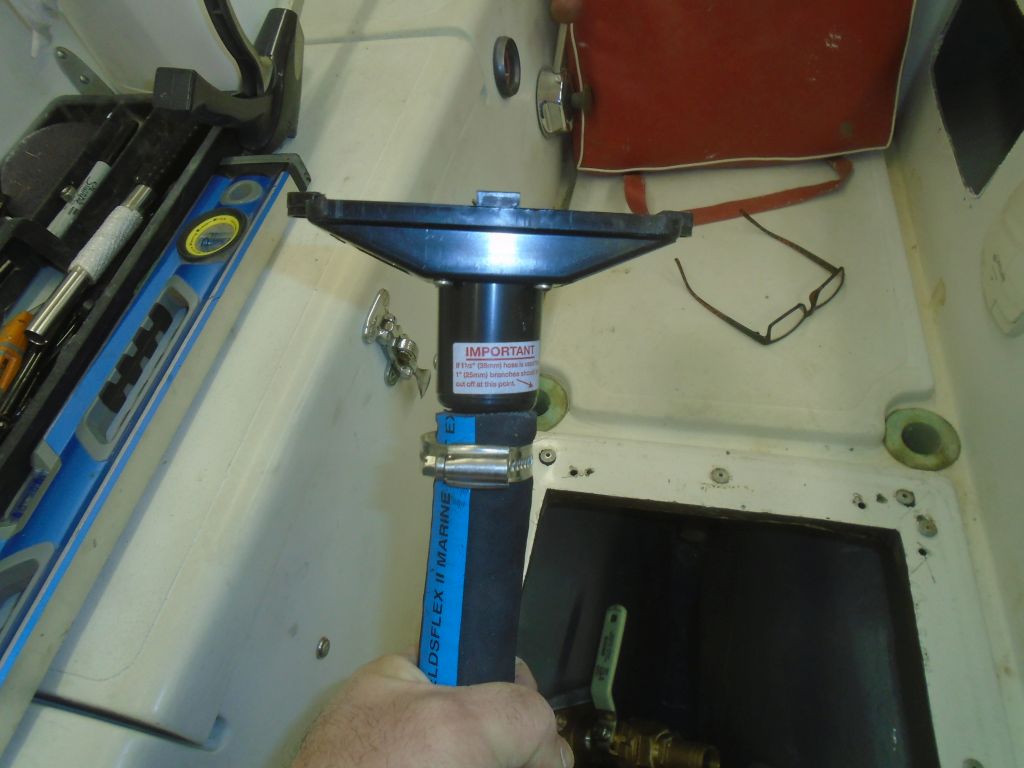
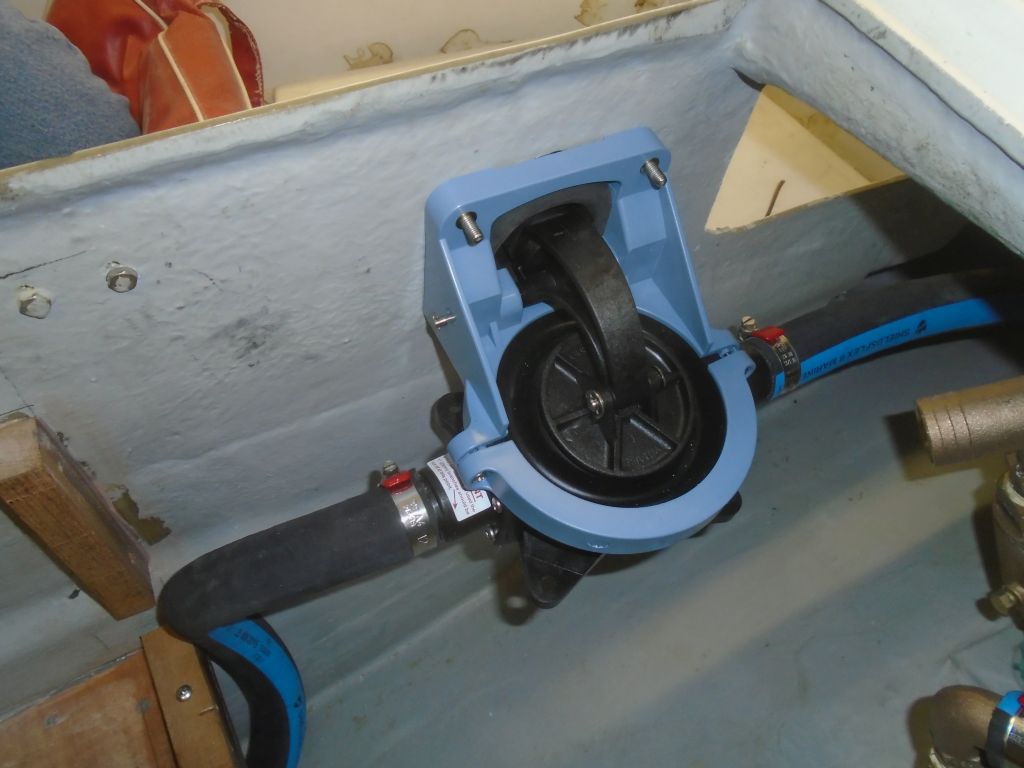
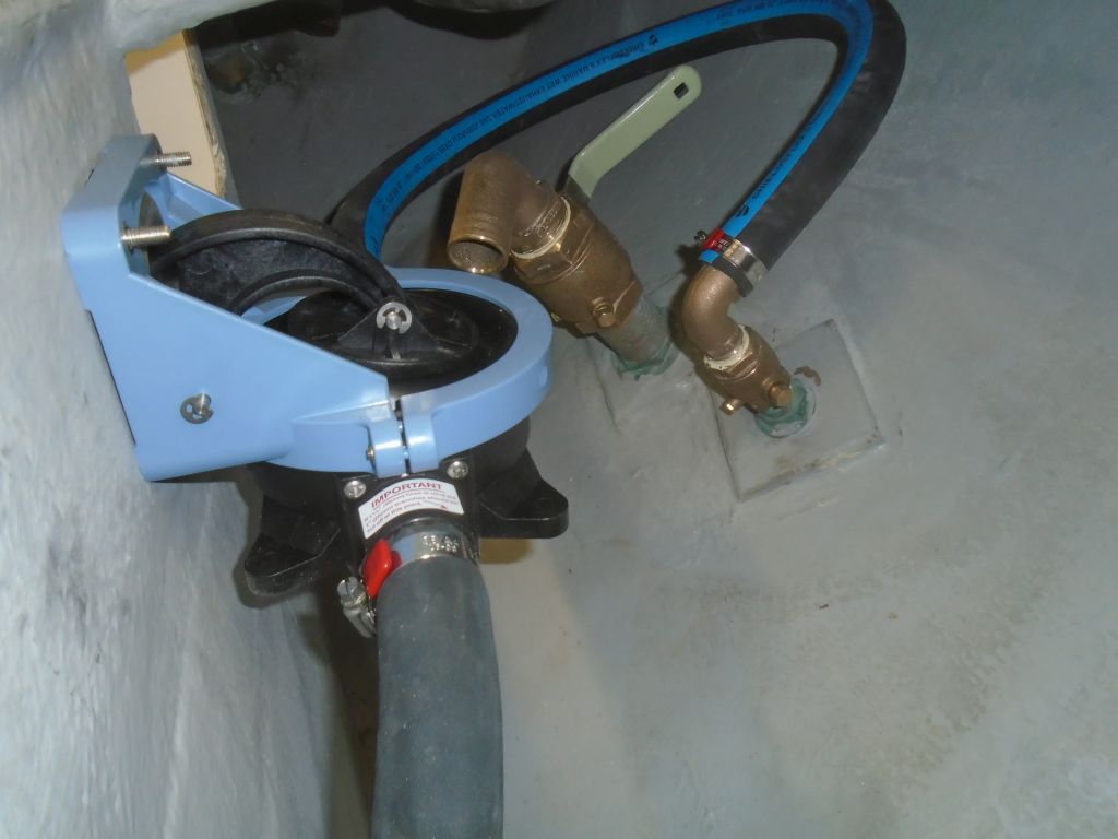
I led a new 1″ hose from the cockpit bilge pump into the bilge sump, equipping this hose with a suction strainer as well, then completed the bilge pump discharge to its overboard fitting. Later (not shown), I added a hose support clamp at the forward end of the pump to keep the suction hose clear of the nearby battery box.
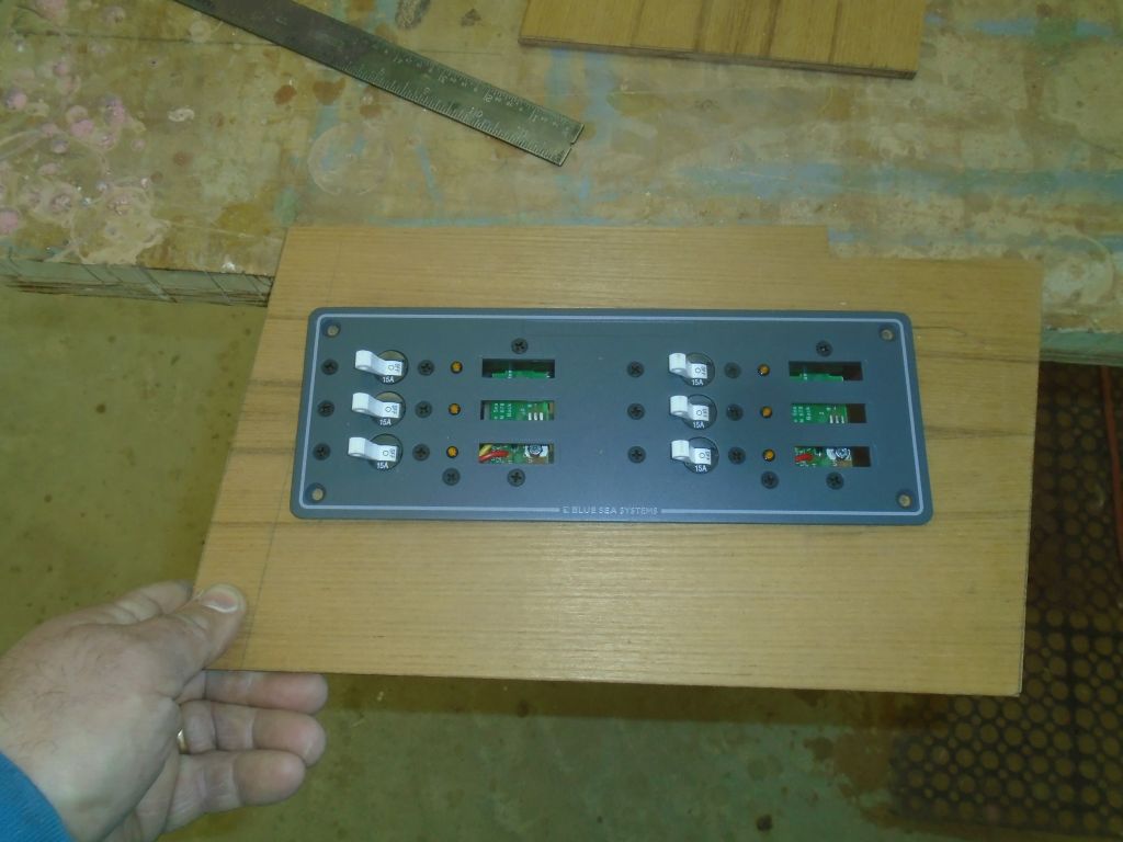
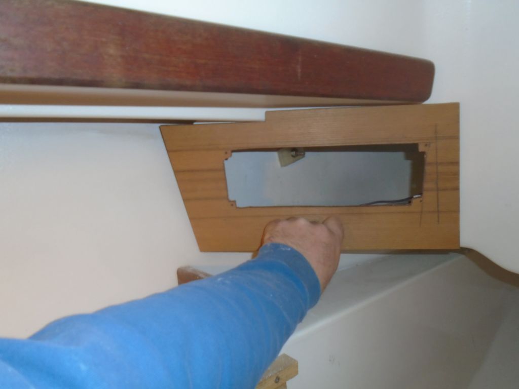
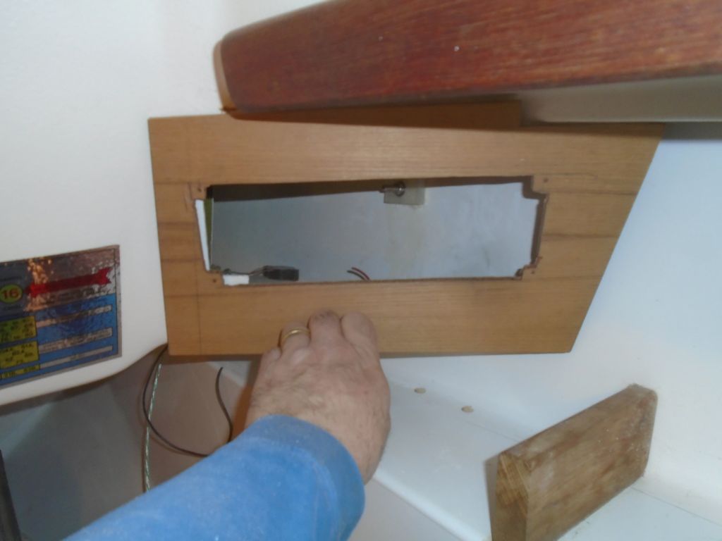
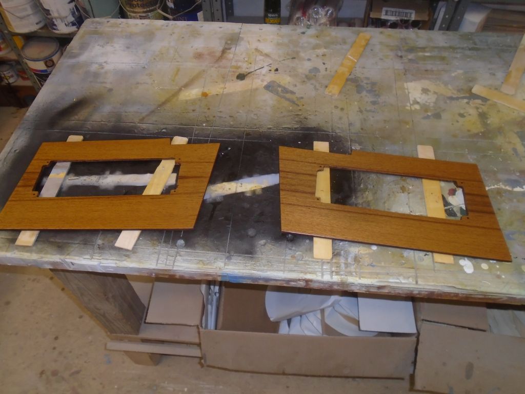
I’d be turning to the new wiring soon, and before I got to that I wanted to be sure the electric panel locations were ready. I knew I’d need to modify the existing openings in the angled panels at the aft end of the cabin, so I used my paper templates to prepare two teak panels to cover the area, and laid out and cut out the openings in the new panels to accept the chosen six-position service panels.
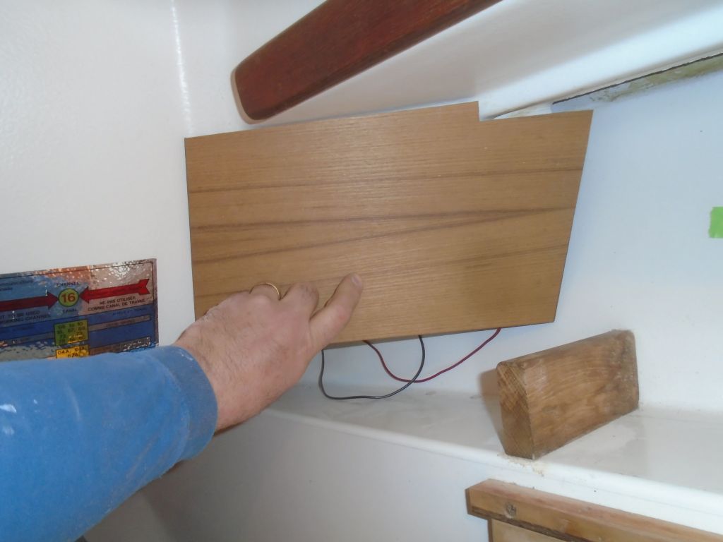
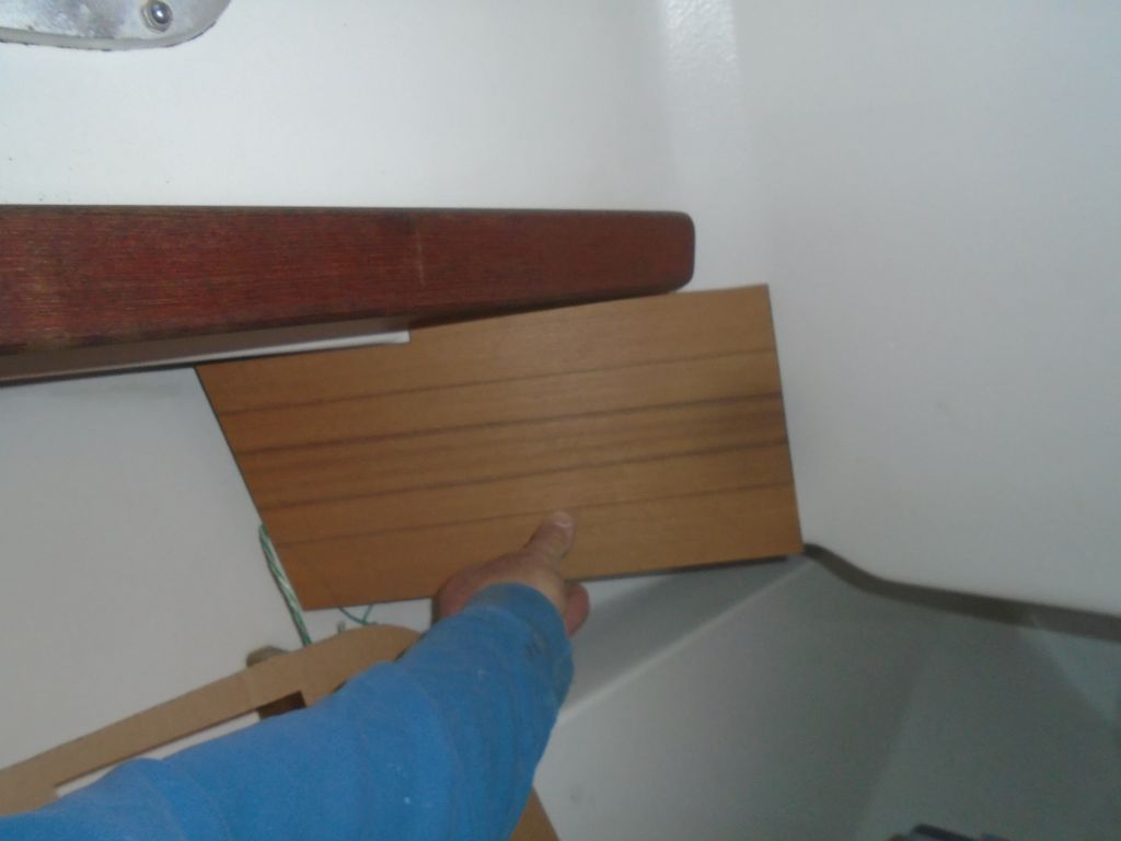
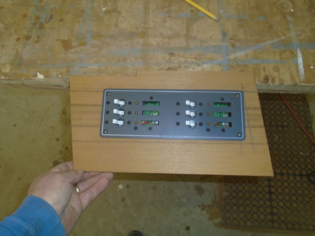

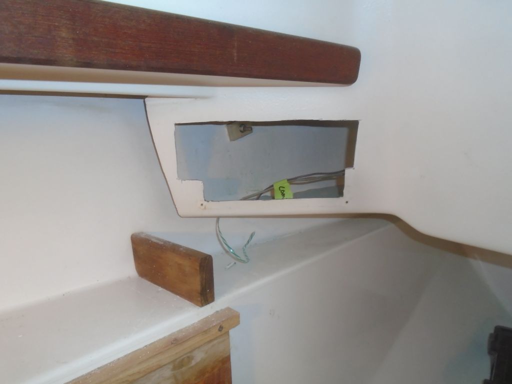
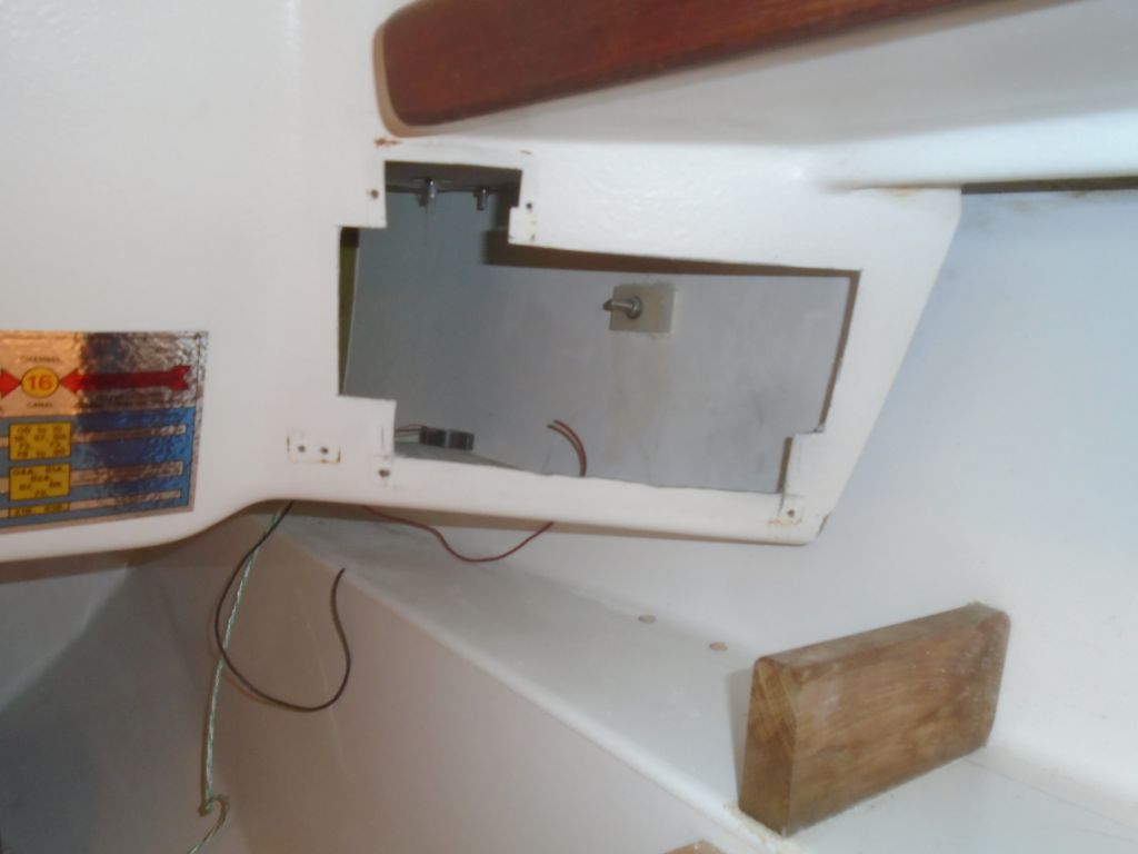
With the panels and openings prepared, I could trace out the new opening on the existing panels and cut out what was needed.
To match the existing interior woodwork, I finished the new teak with teak oil, applying a few coats over the balance of the day.
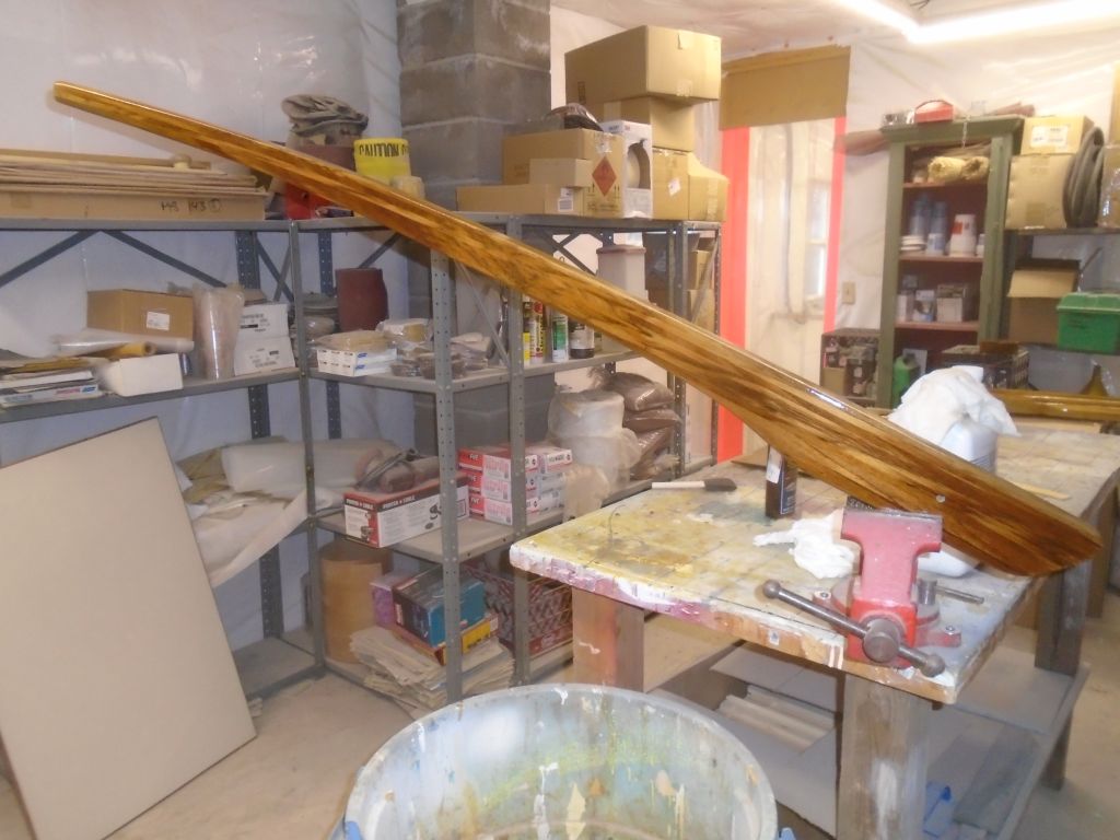
Meanwhile, I continued work on the tiller varnish–coat #3.
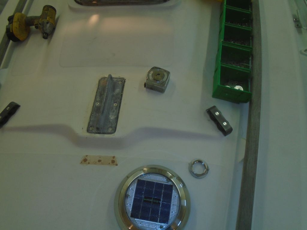
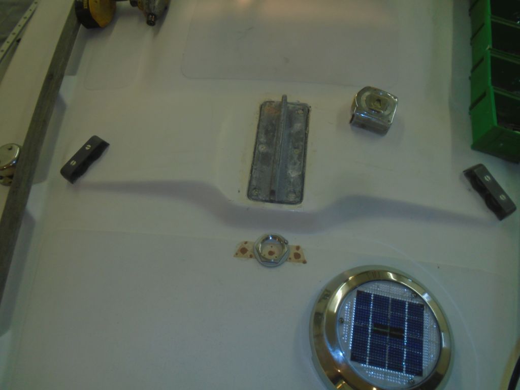
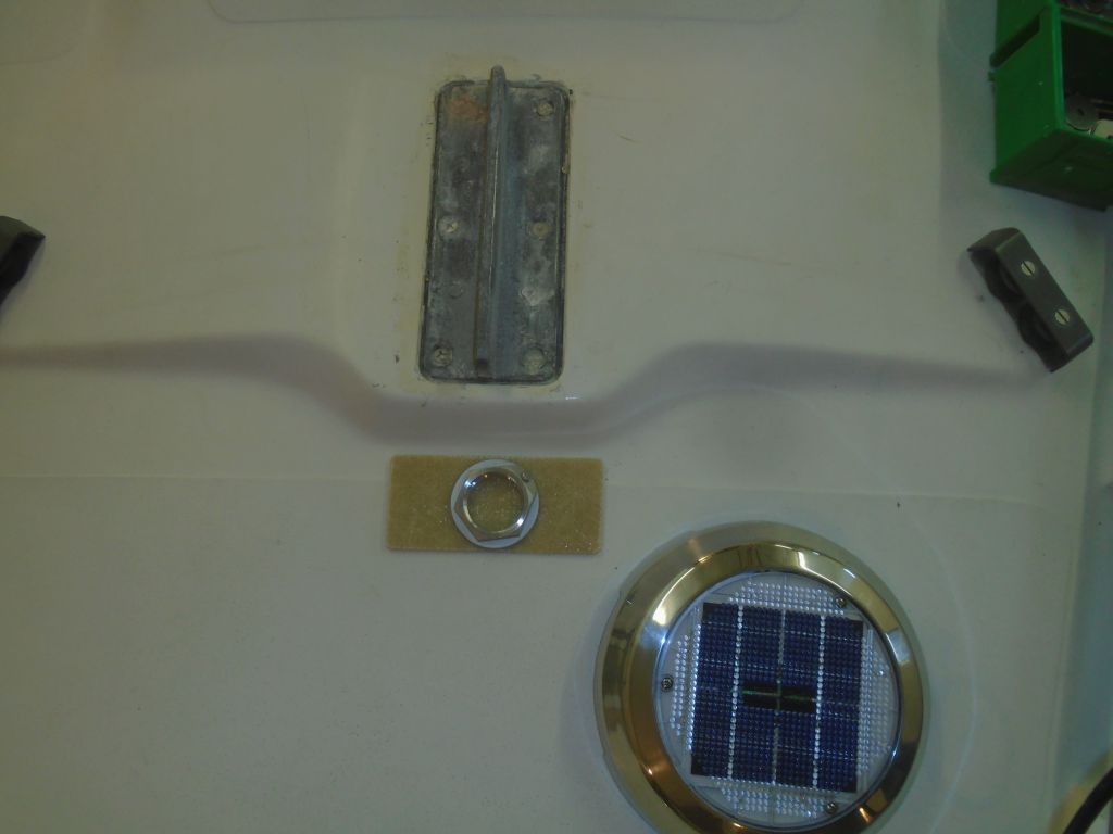
The mast wiring was to be rerouted outside the mast base and through a new deck fitting, and, wanting to drill and properly prepare the mounting hole, I worked on layout now. Ideally, I would have liked to have the wire come into the boat in a hidden area, like within the port locker forward of the galley, but this was simply too far outboard and away from the mast to be practical. The closest possible location is represented by the through hull nut placed on the deck aft of the solar vent, and the corresponding area below would be to the right of the solar vent inlet–any closer to centerline would be exposed in the main passageway. Unfortunately, this location wasn’t going to work.
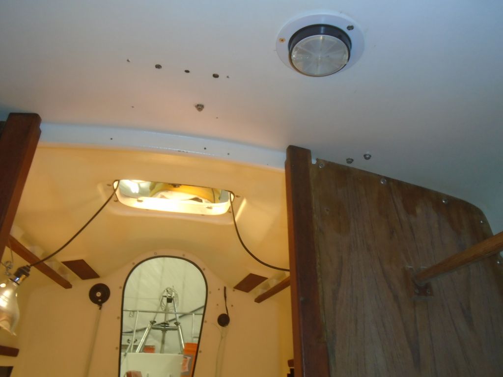
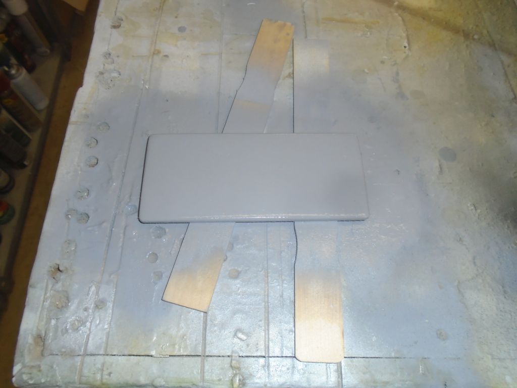
However, there was already a teak cover, left over from the old wiring installation, that would hide the area in the center of the passageway, so I thought the fitting could be installed there, directly ahead of the mast, and then the wires routed through the existing trim system below. This would also help me hide the old–now filled–mast wiring locations, and kept the mast wiring conduit close to the spar and out of harm’s way. So from some 3/16″ thick fiberglass sheeting that I had on hand, I built a little panel that could cover (cosmetically) the old patched holes, and also give me a mounting location for the new 1-1/4″ through hull that would serve as the main wiring conduit. Afterwards, I applied some primer to the new panel to prepare it for paint before installation.
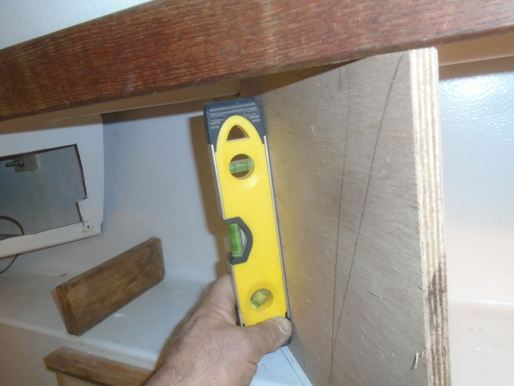
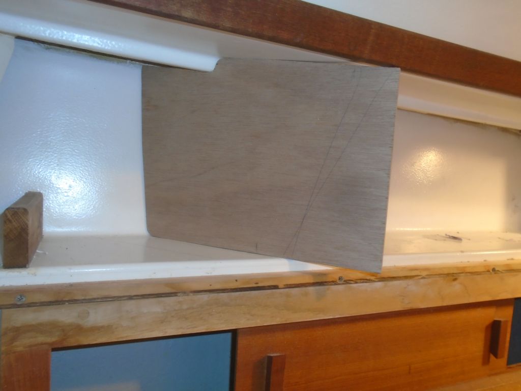
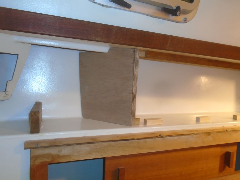
With my electronics locker concept winning approval from the owner, I moved forward with the actual construction. Using my rough cardboard mockup as a guide, I scribed the shape of the area on each of the two panel sections, and used this to create–over a series of test-fits and adjustments–the after angled panel first. To support the panel now and in the final construction, I added a hardwood cleat on the bottom shelf, and later, with the plywood panel in place and properly plumbed, added a second cleat on the overhead to hold the panel vertically, For now, I left the end of the panel to run wild, as the front panel would overlap it and I needed to complete some additional layout before I could make the final cut. This was the structural part of the new panel, made from 12mm marine plywood; when all the cuts were done, I’d cover it, and the front panel, with teak plywood.


The front panel was to be flush with the edge of the molded shelf and, at the forward end, with the molded galley cabinet. The final panel thickness was to be 3/4″, so support cleats and layout lines needed to reflect this when I transferred the layout marks aft to the angled panel. Also, the angle at the forward end, where the panel would meet the galley, wasn’t necessarily a plumb line, so I glued together a simple jig at the same angle, and used it, along with another piece of wood cut at an angle on top, to mark the aft end appropriately.
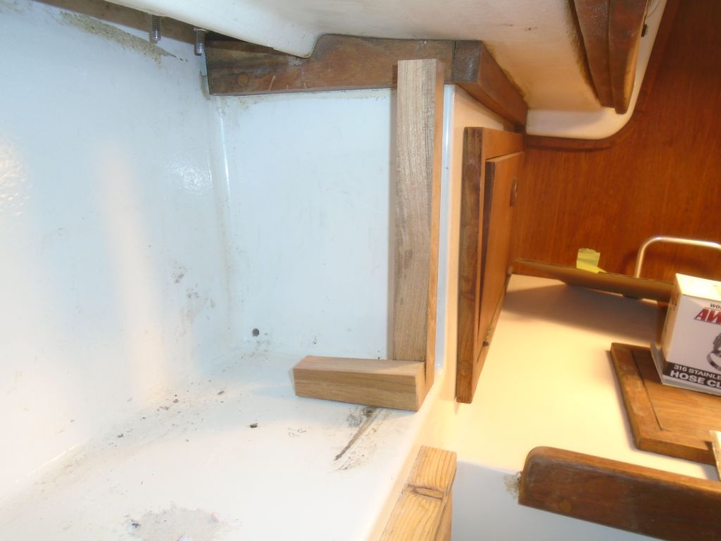
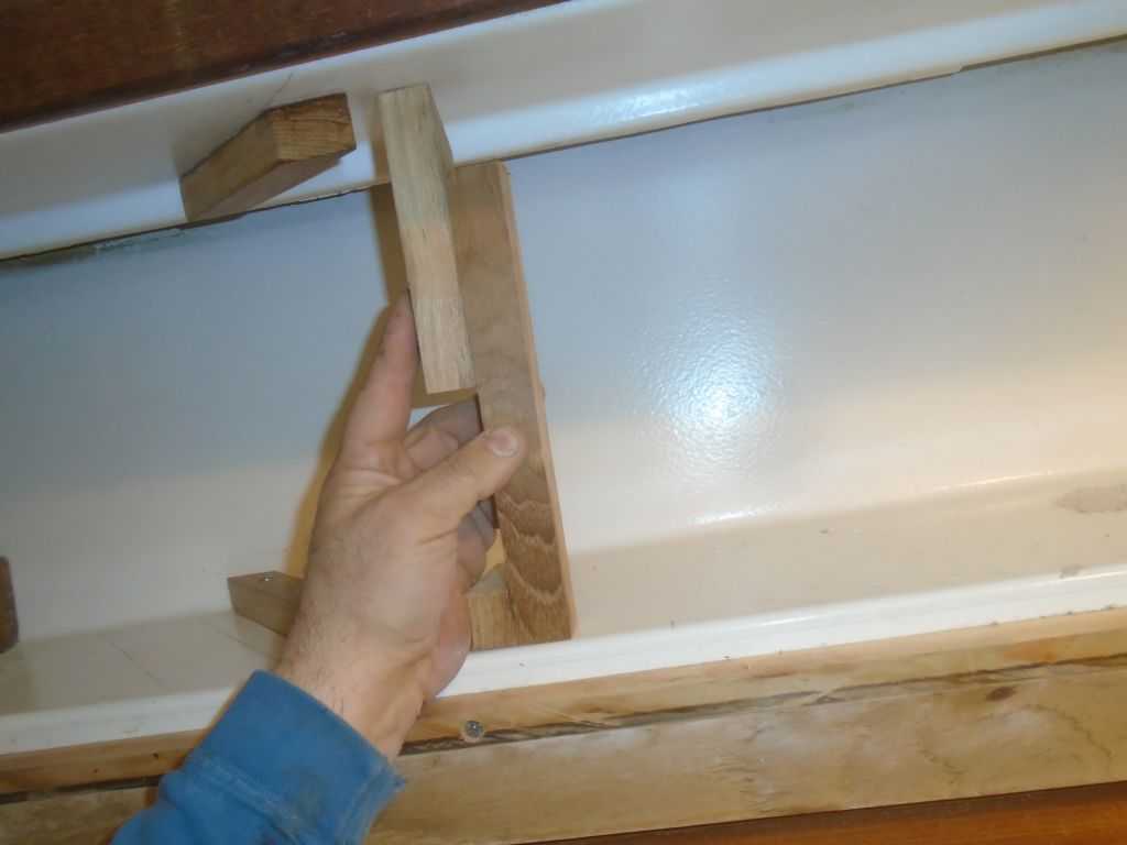
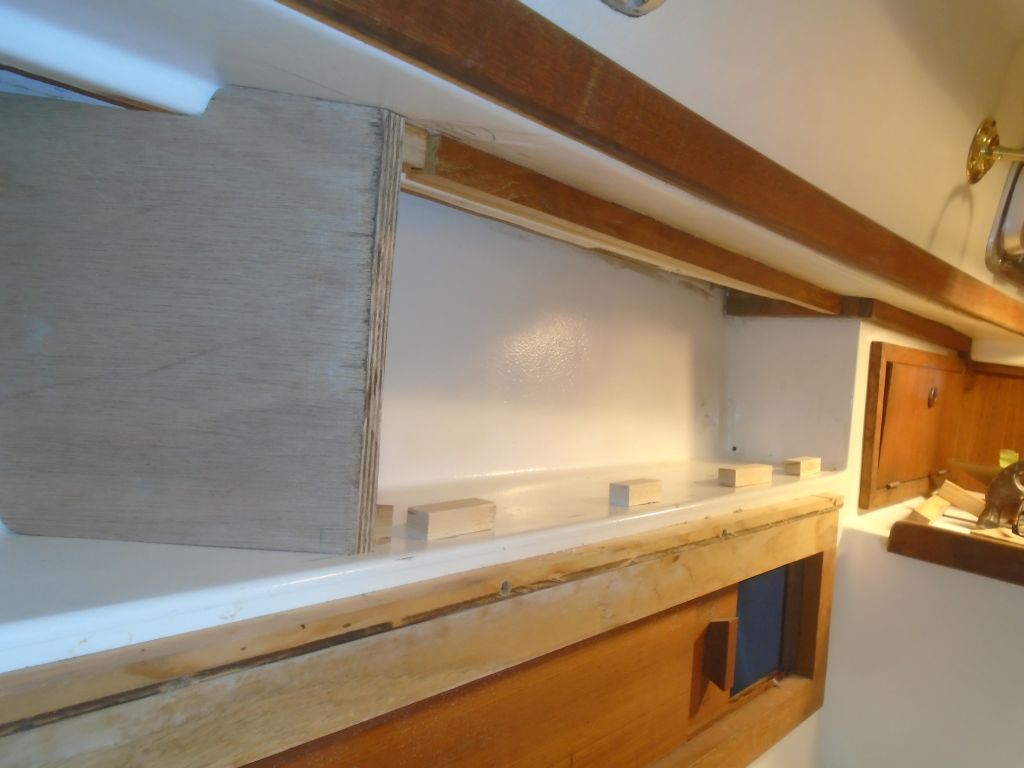
From there, I could cut and install (with epoxy and, to hold it while the epoxy cured, some dabs of hot glue) an upper support cleat along the overhead. The bottom edge of the panel would feature a hinge that would secure it to the existing cabinet, but for layout purposes I glued in some temporary support blocks.
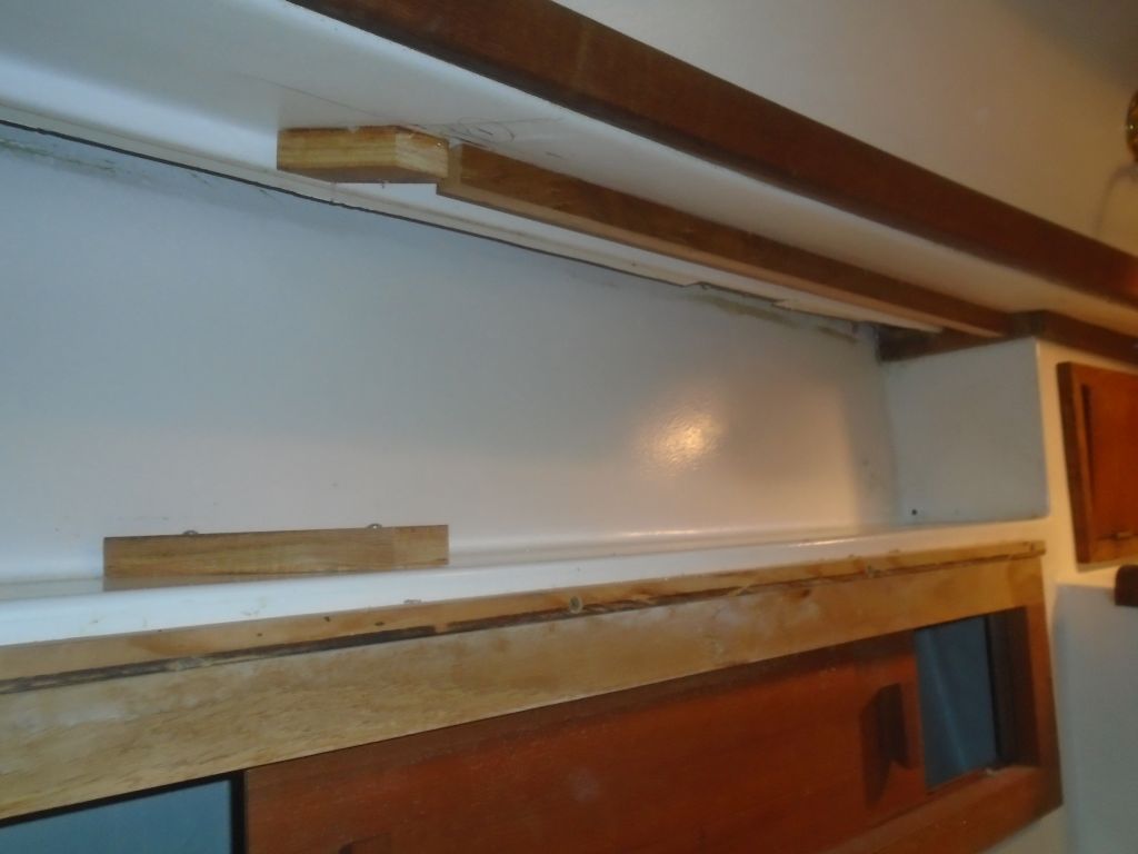
With the inner edge of the front panel thus determined, I could now mark the angled aft panel at the correct spot top and bottom, and cut the end on an angle so the front panel could pass over it. This angle (which mirrored the angle of the molded electrical panel area) turned out to be 45°.
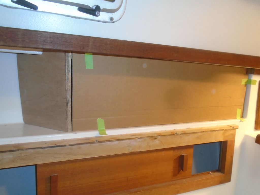
With the cardboard version of the front panel in place, I could scribe its edges, and I’d use it to prepare the structural front panel next time.
Total time billed on this job today: 7.25 hours
0600 Weather Observation:
25°, clouds and flurries. Forecast for the day: Chance of snow or sleet, high around 33°