March 30, 2016
Salty 30
Wednesday
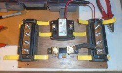
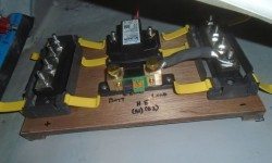
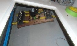
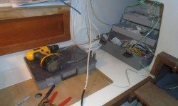
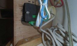
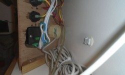
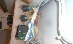
Moving forward with the battery buss assembly, now that the epoxy-coated platform had cured, I pre-assembled the various components on the board. Considering how the wires would eventually lead, I decided to turn the ACR around so the wires would come out cleanly on the free side of the platform. Before final installation, I pre-wired anything I could, including a negative lead between the shunt and negative distribution, and a small fused ground wire from the ACR Then, with the hull prepared in the bonding area and a small block hot-glued in to hold the platform against sliding, I epoxied the assembly to the hull and left it to cure.
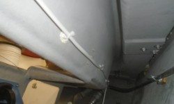
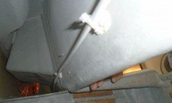
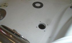
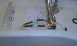
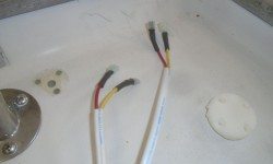
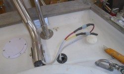
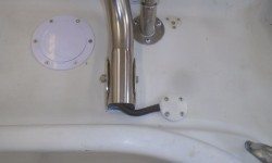
To wire the stern light, built into the Monitor windvane, I led aft a wire pair along a pre-determined route behind the cockpit coaming, then, next to the support tube base containing the stern light wire, installed a side-entry cable clam to accept the wire. This section of the deck was non-cored, so I didn’t need to do any special hole preparations. To allow for possible removal of the windvane, I made up the stern light wiring with removable connectors, leaving enough slack belowdecks to allow the wiring to be disconnected if needed. Back at the electrical panels, I ran the bitter end of the wire across from port to starboard, so I could join it with the bow light wiring to a common breaker on that side.
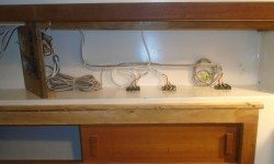
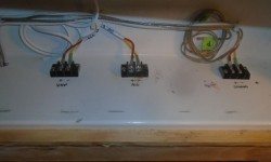
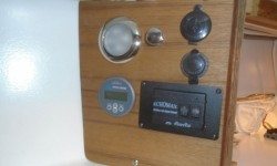
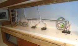
Meanwhile, I continued with the final wire runs on the port side, beginning with three circuits up into the new electronics locker, where I installed terminal blocks to allow easy removal of the entire front panel (which would include the various electronics), which the owner had requested. For now, I tucked in spare speaker and VHF cable wire while awaiting the final connections of those items.
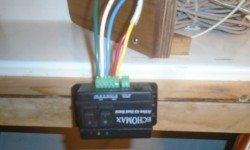
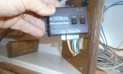
I connected the required five wires to the RTE control box, including a power supply from the panel, then the three wires from the mast wiring. I led aft the two wires that would supply power to the masthead all-round white light, which would be switched separately. I wired the RTE box from the bottom, highlighting why I needed the extra space carved out of the back of the panel. To access the screws that clamped the wires in place, I had to remove the control box from the mounting kit temporarily. There was a set of back wire terminals a little higher up, but I didn’t have any sort of connectors in my inventory that fit the terminals therein.
Later, I installed a simple pull switch to operate the LED night light in the panel (which would be incorporated into the cabin lights circuit), and secured the various wiring in the new electronics locker.
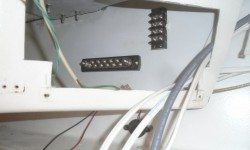
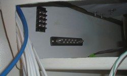
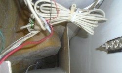
I thought that was pretty much it for bulk wiring circuits, and now I was ready to move on to the final termination of all the new wires. To begin, I untaped the glued-on terminal blocks in the two locker areas, and, on the port side, secured up and out of th e way a mass of transducer cable for the knotmeter.
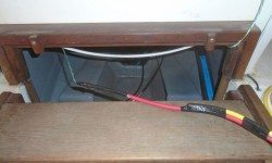
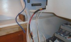
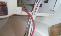
To connect the panels and distribution busses with the battery system, I ran battery cable into each of the two electric locker areas through the hidden wire conduit behind the bulkhead, hopefully the last wires I’d have to lead through.
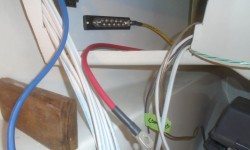
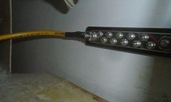
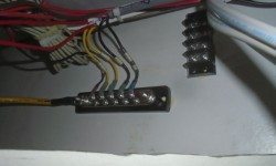
Then, I made up the ends, connecting the yellow wire to the negative distribution buss on each side, and leaving enough slack in the positive wire to allow for connection to the panel later, and to allow removal of the panels for wiring and servicing.
Finally, I began to make up the negative wire ends, starting on the port side. I labeled each wire with its circuit number as I went. I’d continue this process with the remaining wires, and eventually make up the positive ends to the panels and terminal blocks as required.
Total time billed on this job today: 6.75 hours
0600 Weather Observation:
25°, clear. Forecast for the day: Sunny, 50


