

September 29, 2016
Acadia 9
Thursday
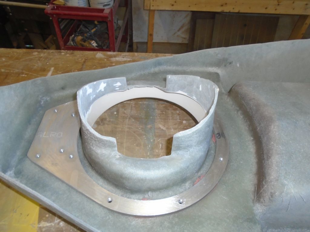
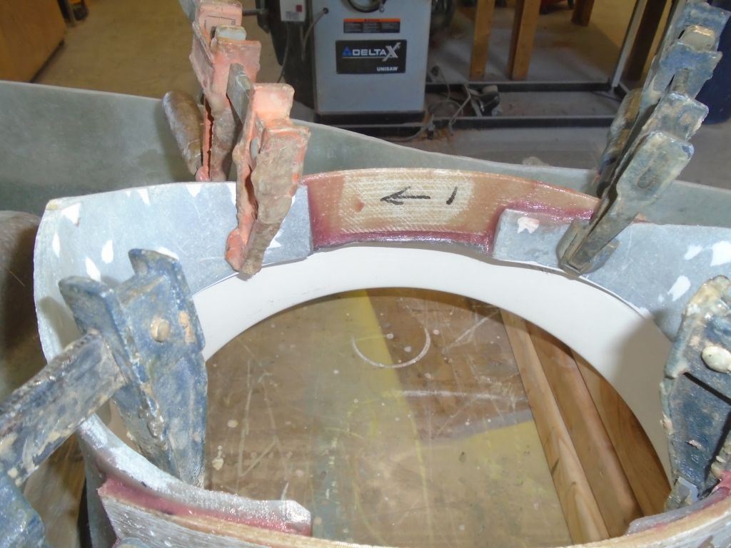
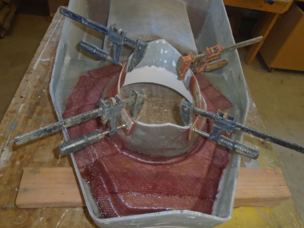
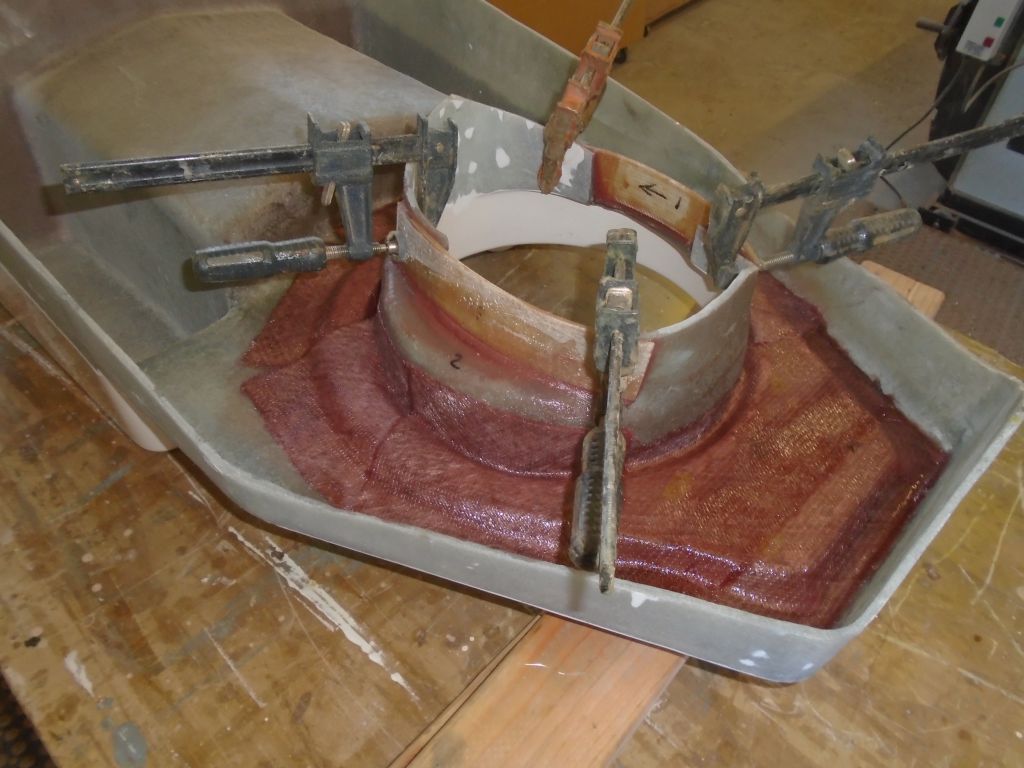
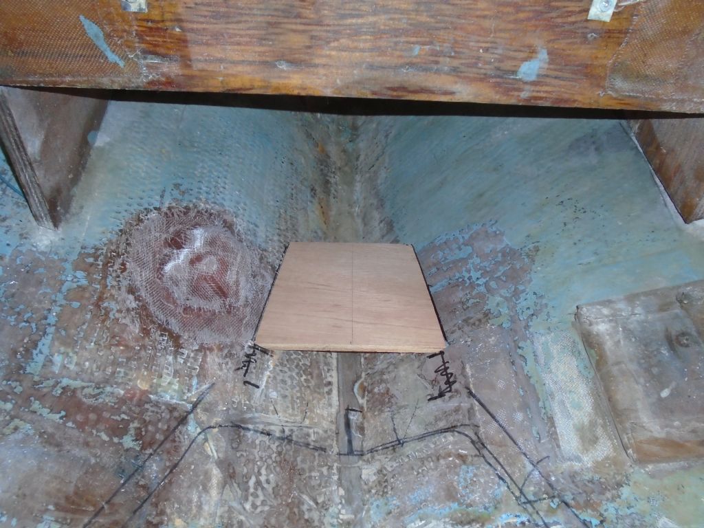
Now that the backing ring was secured, I could remove all the mounting studs that had aligned it while the epoxy cured. Then, I focused on creating new sides for the Saildrive leg opening, where I’d cut out the material earlier to allow the leg to spin as required. The new sides would make it easier later to glass in the opening from outside, but needed to follow the curvature of the cutout so as not to impede the rotation of the drive leg during final installation a little later.
I happened to have on hand some leftover strips of epoxy laminate that I’d made for some previous project, and they were just right for the job: the right width, and the right thickness to be flexible enough to bend to the curve, yet stiff enough to hold that curve appropriately and maintain the width of the opening required for the drive leg rotation.
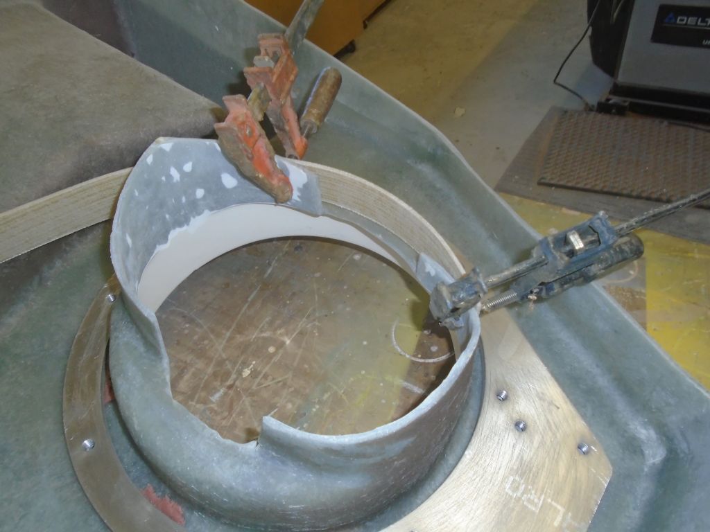
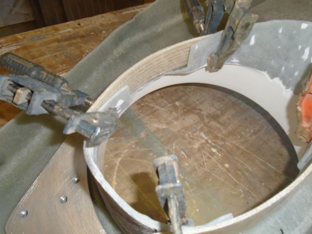

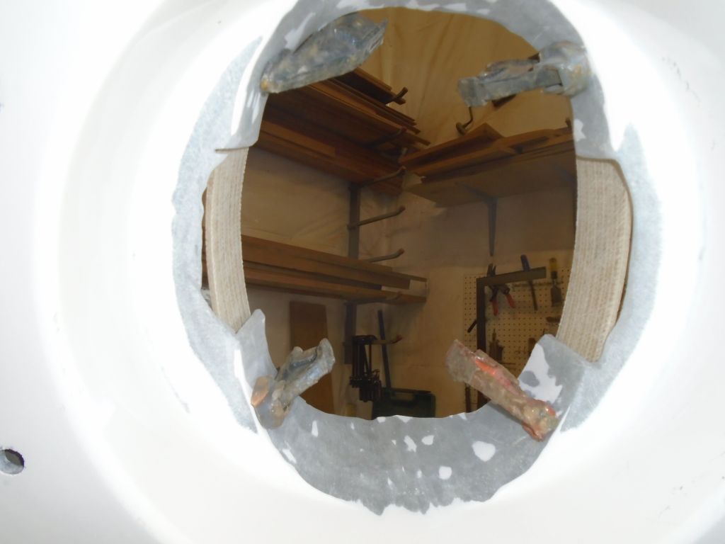
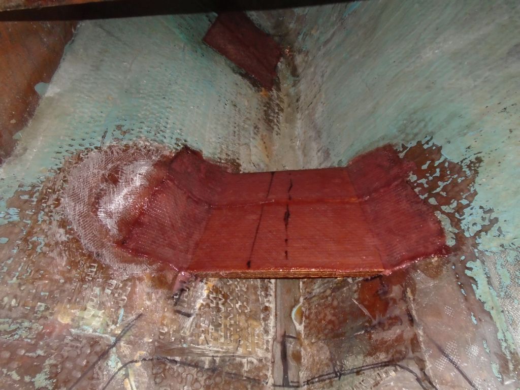
I secured the new pieces with thickened epoxy adhesive, clamping them securely and near the ends of the s trips to spring the curved center portion well outward, following the curve of the top cut in the foundation. Later, once the glue was cured, I’d trim the excess material as required, since the strips were constant width and the opening featured an angle or curve. I filled the small gap between the bottom of the new sides and the existing foundation with an epoxy fillet, and planned to glass from the inside (i.e. the bottom, exposed side) now, as well as from the outside (inside the hull opening) later, once everything was in place.
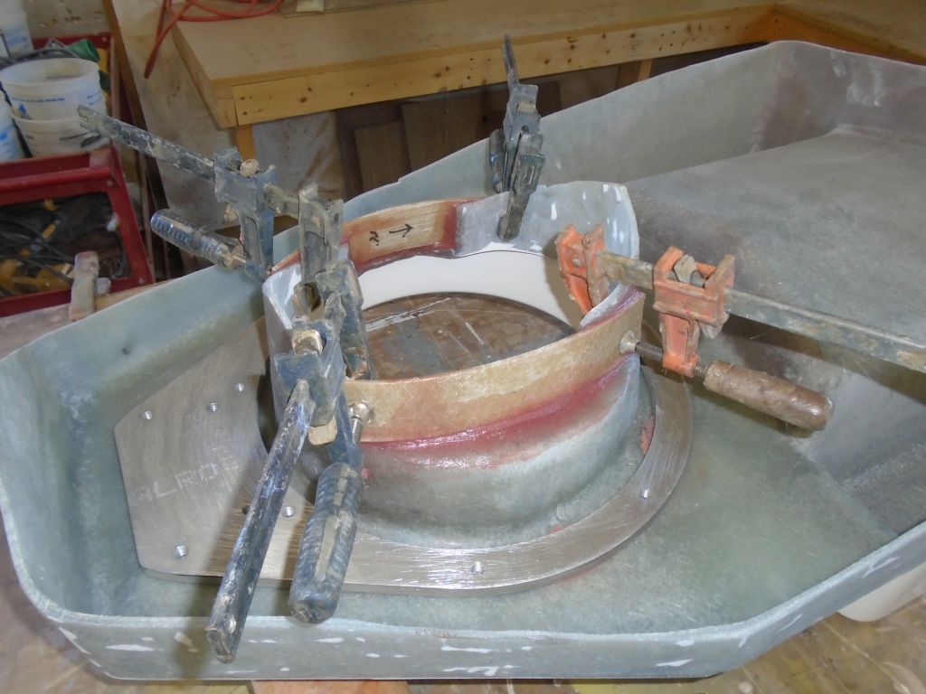
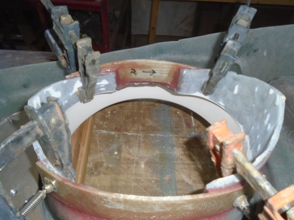
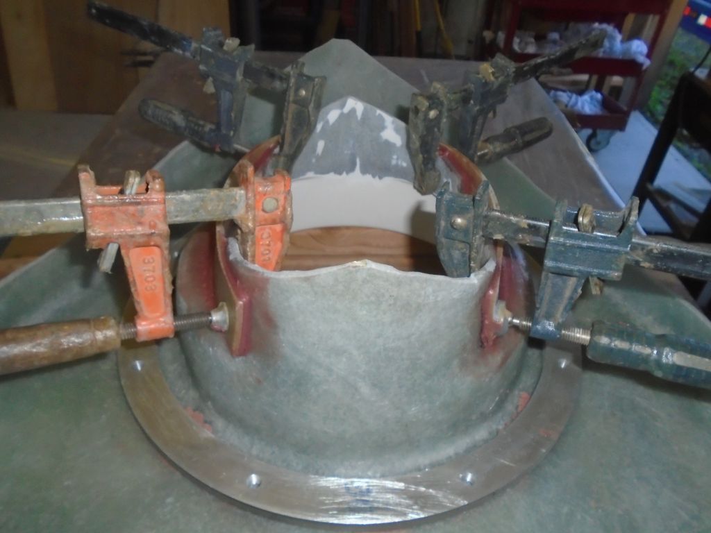
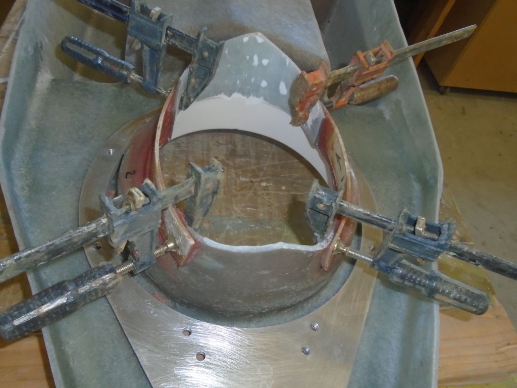
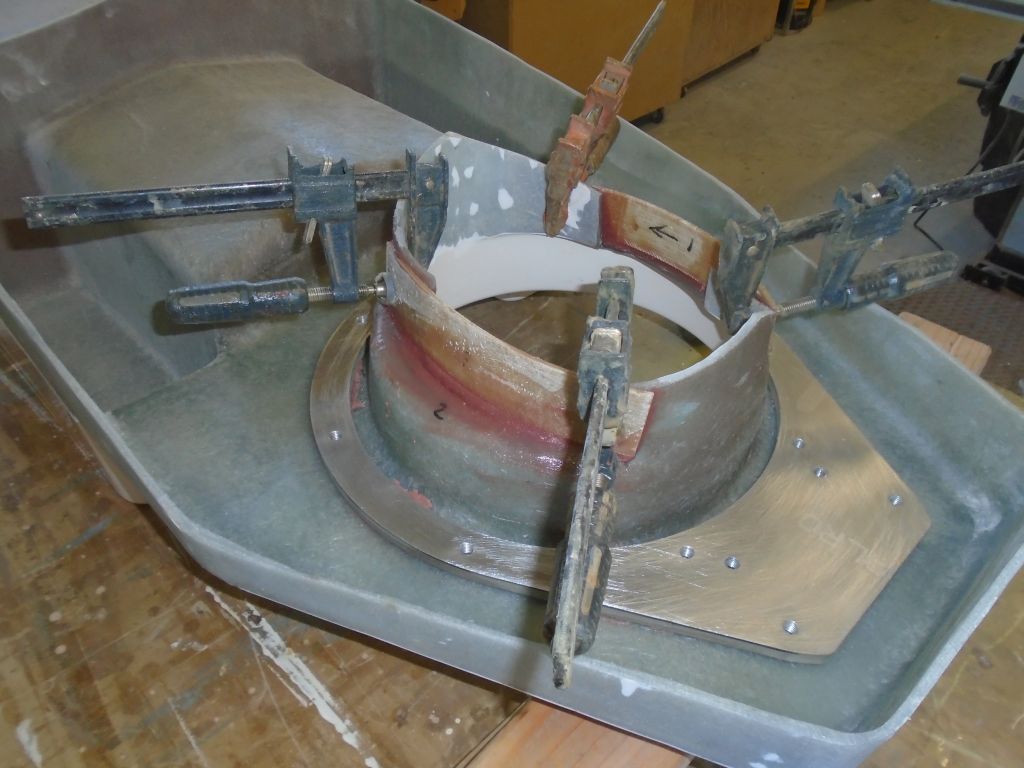
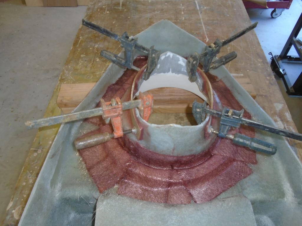
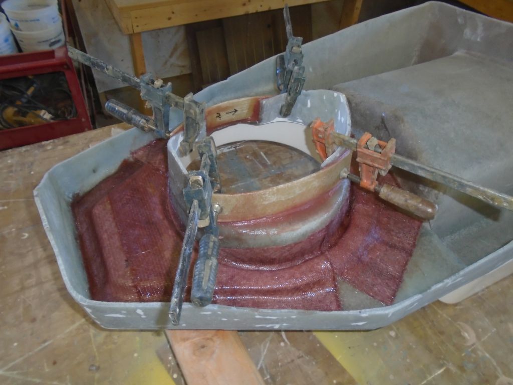
I scuffed up the top of the aluminum backing ring, and placed small bits of tape over all the threaded holes for protection. Then, I fiberglassed it in place with various pieces of tabbing and epoxy resin. I didn’t get fancy in the preparations (i.e. angled fillets and smooth edges around the ring) because I saw no call for it, as this tabbing really only secured the ring against movement during installation of the leg. and provided no structural requirements beyond that. Frankly, the epoxy adhesive bonding the ring would have been sufficient as is, but it was a simple additional step to complete. The tabbing encapsulated the ring and secured it to the foundation on both sides; the masking tape prevented the resin from fouling the bolt holes and, in this installation, had no bearing on the function of the tabbing as required.

Leaving the new glasswork to cure, I prepared to focus on myriad ancillary tasks that lay ahead before I would actually install the engine foundation and engine. These tasks included directly related systems such as the fuel and exhaust system, but also indirectly involved existing systems like the fresh water and electrical systems, namely how these systems ran through and were installed in the engine room. With a wide-open space, now was the time to square away these details. To that end, and planning ahead, I began to prepare an order for various materials that I’d require to complete these installations and changes, and assessing on-hand inventory as needed.
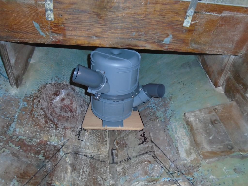
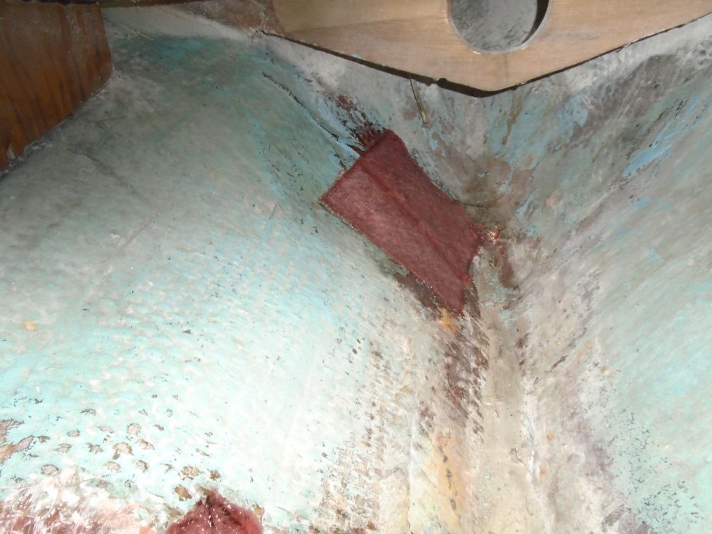
One of the immediately related installations was a new waterlift muffler for the exhaust system, as the original was in poor condition and I’d discarded it. The owner had purchased a new muffler along with the engine, and with this on hand I determined its future location just aft of the engine room, The muffler allowed rotation of the inlet and out let ports, as well as the top and bottom of the unit, which made it easy to configure for the specifics of this installation–a handy feature, since (as usual) space was at a premium behind the engine. Specifically, headroom was tight in the chosen location beneath the fuel tank, which was where the muffler needed to go in order to remain aft and clear of the new engine foundation.
Satisfied that the chosen location would work, I built a little plywood platform to support the muffler and fit into the shape of the hull. Then, I epoxy-coated the plywood on all sides, and secured it to the hull with some thickened epoxy on the bearing surfaces and fiberglass tabbing over the top and onto the hull. At the same time, I completed the interior patch of the old propeller strut location, which area I first sanded clean, then filled the bolt holes as needed with thickened epoxy, and finally installed as layer of fiberglass over the top.
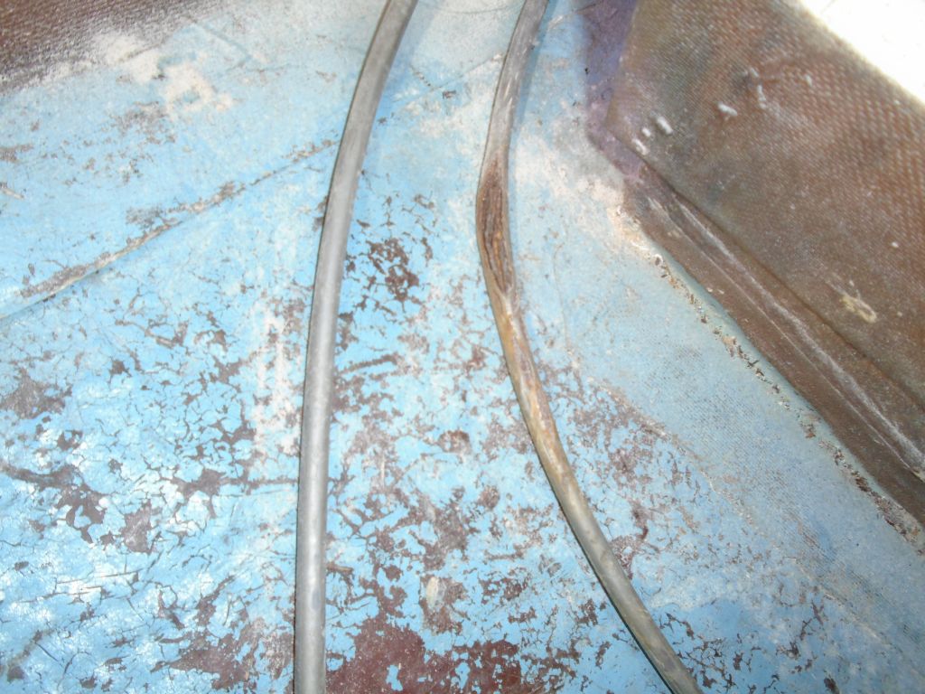
Looking to round out my current order of necessary supplies, I turned to the engine control cables, leading through the pedestal. The old cables were probably original, and one of them was split and damaged, and required replacement.
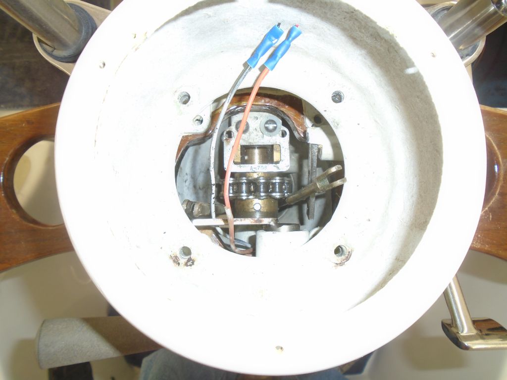
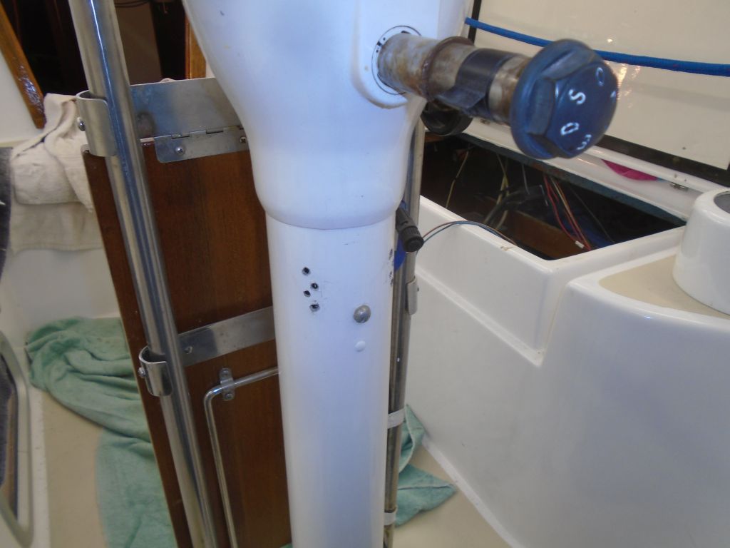
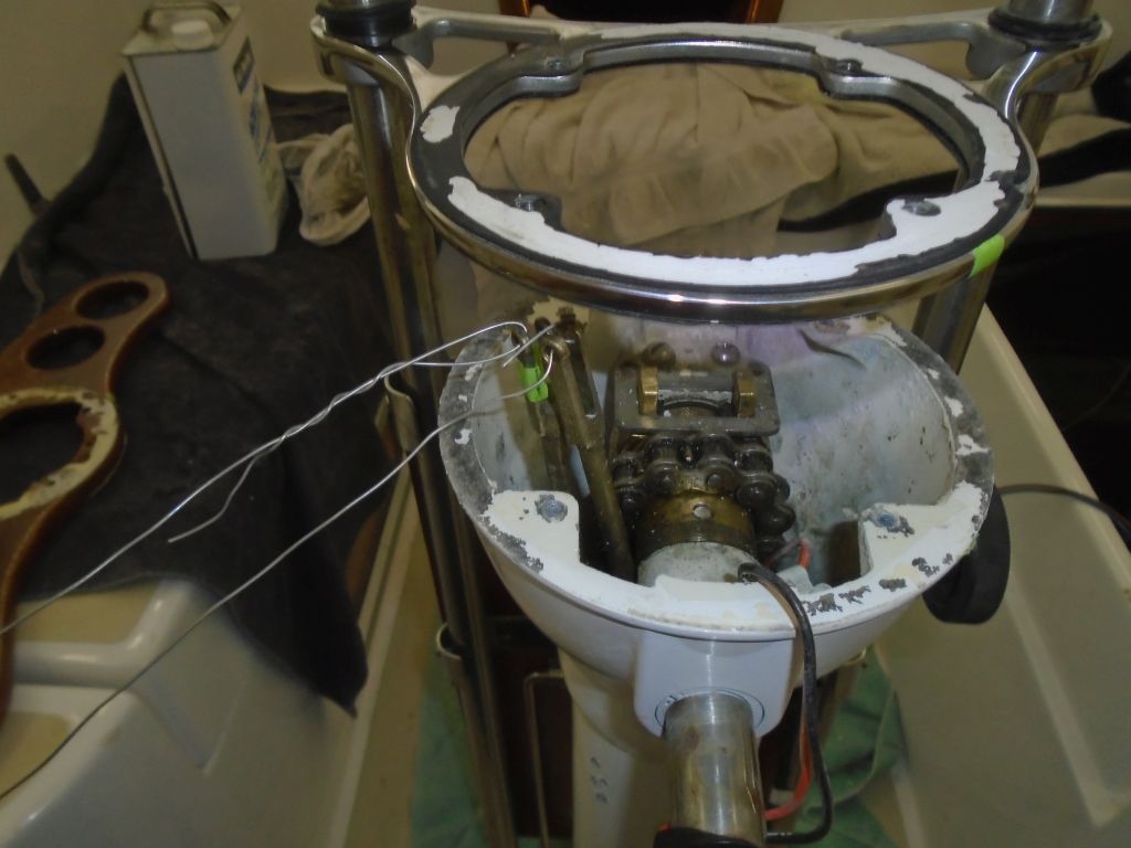
To access the tops of the cables so I could remove them, I removed the binnacle compass, exposing the controls and cable connections. Removing the clevis pins proved to be no problem, but of course there was more to this seemingly simple task than I’d first thought. Though it seemed obvious in hindsight, based on the way these sorts of cables work, initially I’d not considered the fact that the cables would be secured somehow within the pedestal. But of course they were, with what turned out to be a devious little clamping system, and this prevented the cables from moving. As pedestal-mounted control cable replacement or removal had never been something required in my past, I had to consult the online documentation available to determine how to proceed from here.
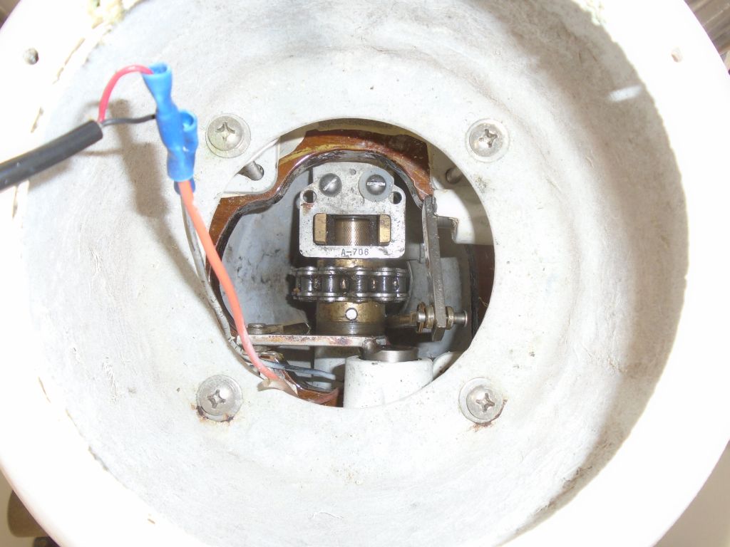
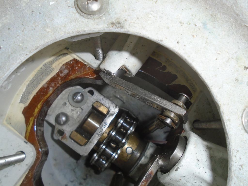
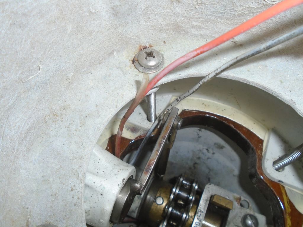

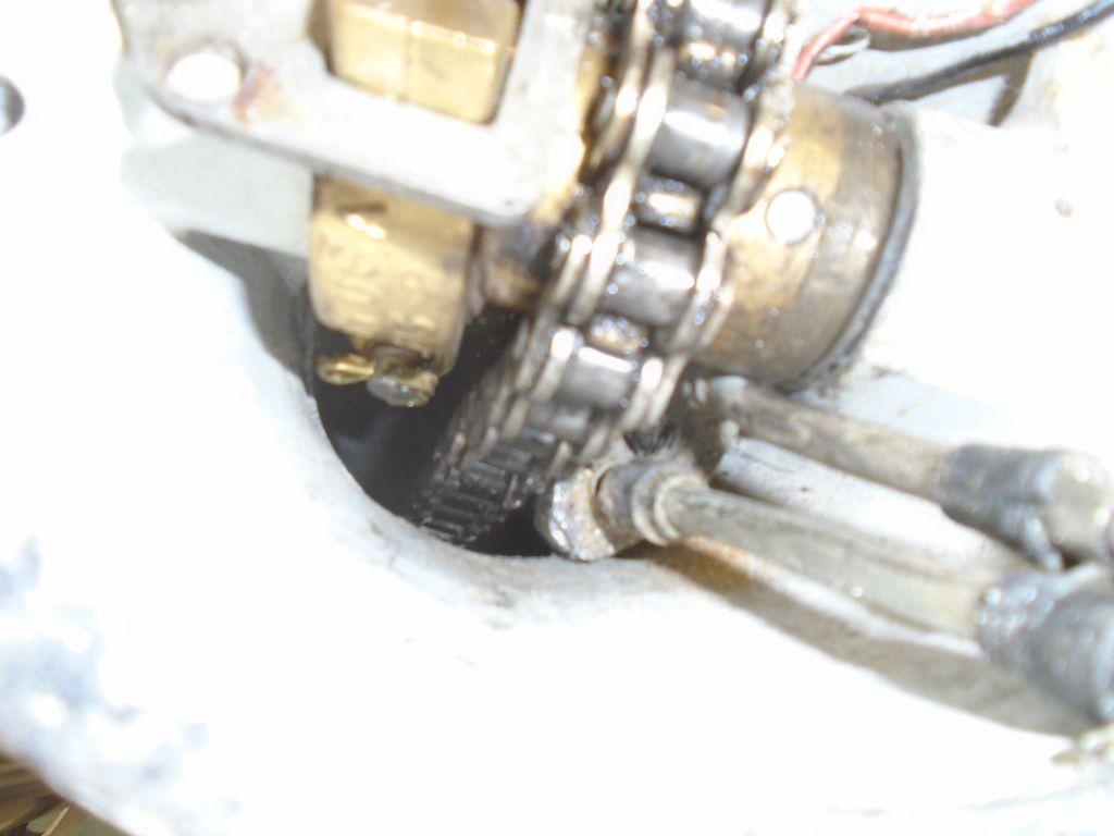
I found that there was an internal clamp below the wheel shaft, with a screw securing it from outside. This screw was hidden behind the autopilot mount, so it took me a while to find it. Releasing the screw-and the clamp was no particular problem. But I knew I was in trouble when I read in Edson’s own instructions that there was “limited room” inside the pedestal to allow the clamp to move. Following the prescribed procedure, which called for pushing the cables–and clamp–down from the top till I could get the throttle cable over to the left (port) side of the pedestal along with the gear cable, I soon found that the cable clamp would not pass by the steering chain, and even getting the cables to one side had required removal of the entire pedestal top to improve access. The instructions suggested the clamp would fit, and allowed further suggestions how to eke it by, but after fighting the arrangement for some minutes, it eventually became clear even to this stubborn and highly annoyed individual that it simply wasn’t going to be removable until I slackened the steering cables and moved the chain off the sprocket.
Lucky you, friendly reader, I will spare here the details of my private thoughts on this frustratingly thoughtless design–as well as some of the specifics of what I went through to even get as far as I did–but I’d sure enjoy the chance to have a little chat sometime with some of the folks who design things that are so eminently unserviceable out in the field. Suffice it to say that spending two hours completely disassembling the pedestal ultimately only to fail to remove–never mind replace– these cables, and necessitating further disassembly of the steering system to effect what seemingly should be (to me) a simple maintenance procedure does not suggest good design. (I didn’t even want to think about the prospects of re securing this cable clamp inside the pedestal later…yet of course I must consider it.) I’d revisit the cable replacement on another day. All I’d really wanted from this exercise was to confirm the lengths of the cables so I could order replacements, and in the end I simply estimated.
Total time billed on this job today: 6.5 hours
0600 Weather Observation:
45°, mainly clear. Forecast for the day: sunny, 60s.