

October 12, 2016
Acadia 16
Wednesday
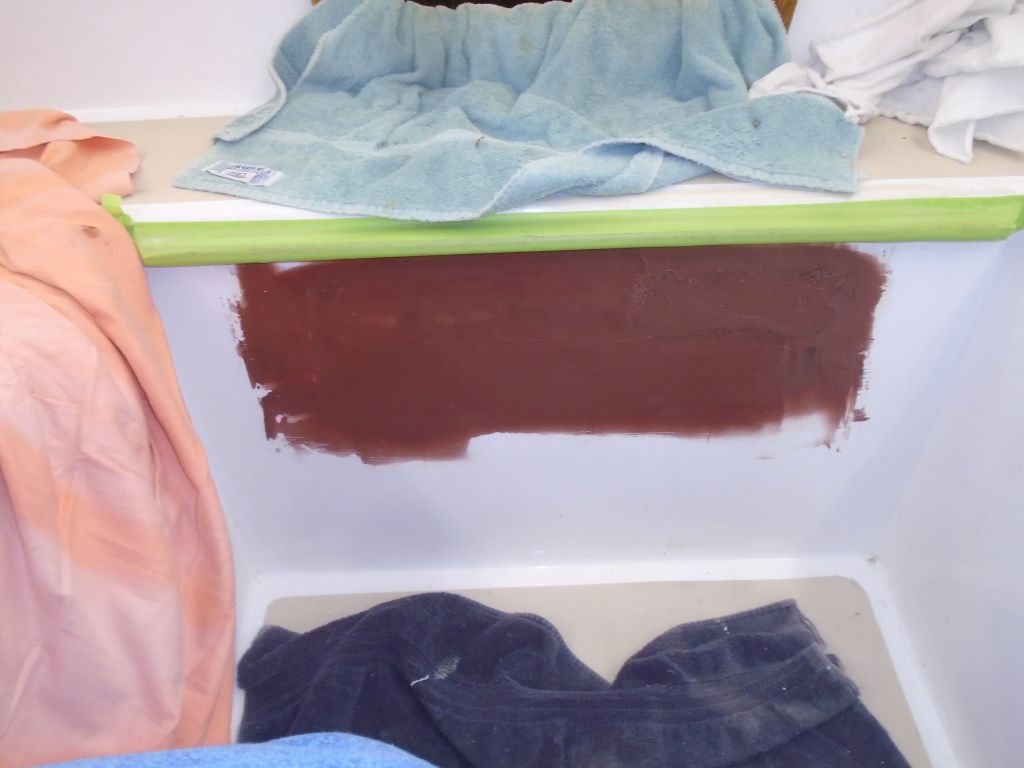
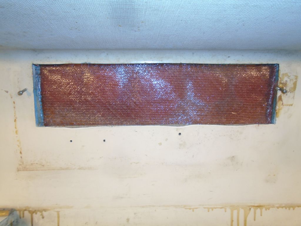
The fiberglass patch over the old instrument gauge holes was ready for sanding, which was my next step before applying a coat of fairing compound over the new laminate on the exterior, and adding a layer of fiberglass over the inside section of the old holes. (I forgot to take a picture of the freshly sanded exterior..)
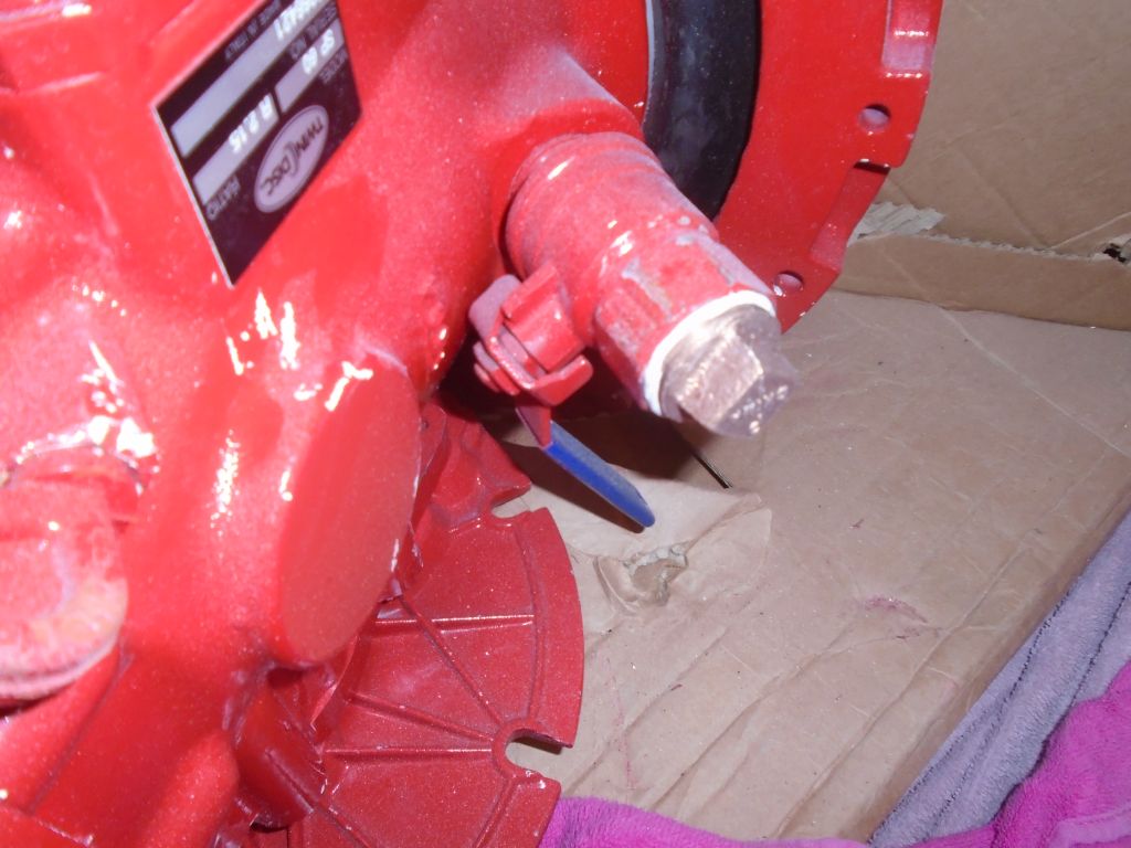
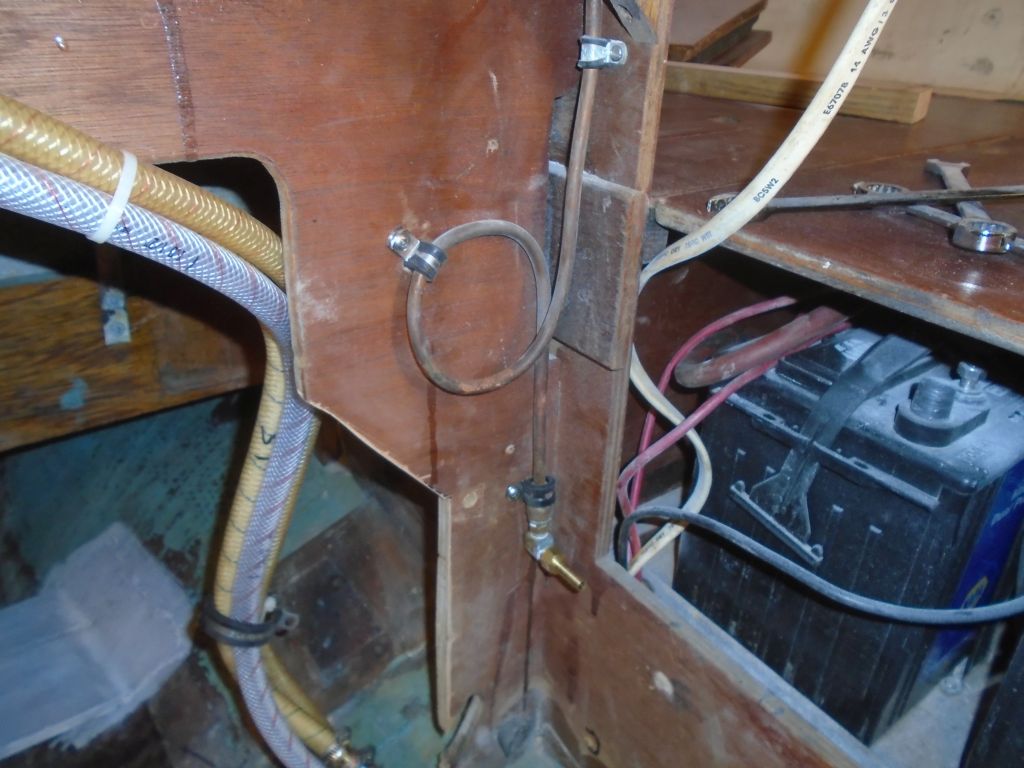
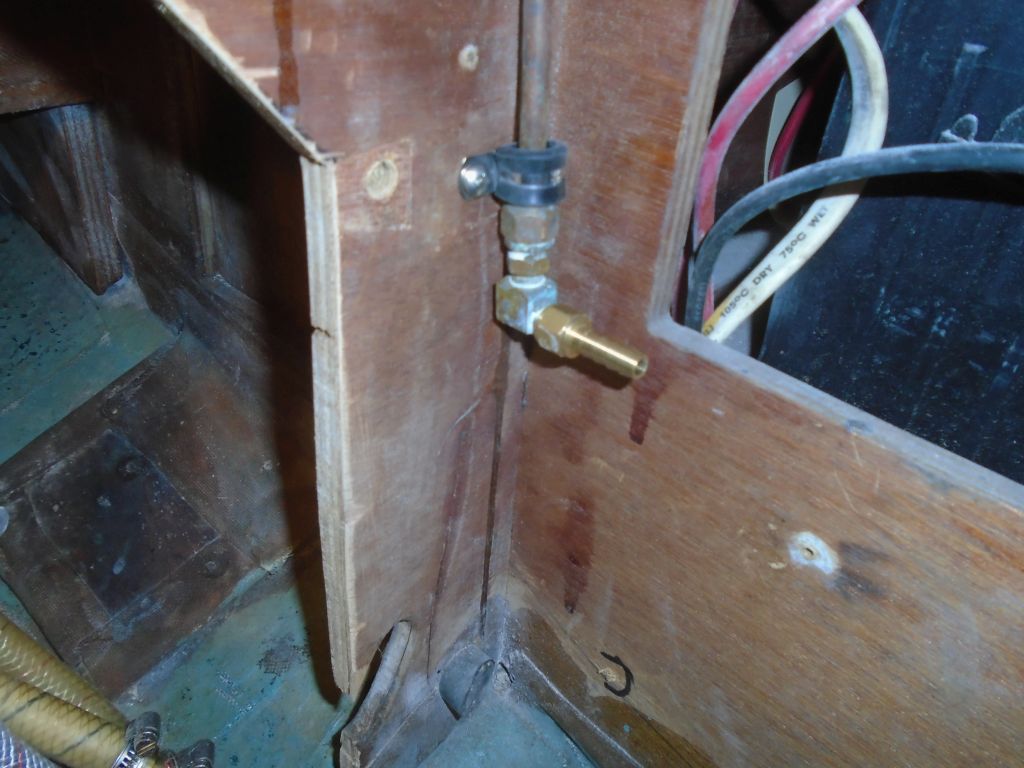
Earlier, I’d removed a hose barb from the integral raw water intake valve on the drive leg. The leg featured a built-in cooling intake system, much like that of an outboard engine, but anecdotal evidence suggested that the little intake ports on the leg could become clogged with debris or marine growth, and would be difficult to clear should this happen. Consultation with Beta Marine indicated that there was no requirement to use the built-in intake versus using a separate intake (already fitted on this boat), and the owner and I decided on this course. I elected to leave the pre-installed shutoff valve in place, but added a bronze plug in place of the old hose barb as a more secure means of keeping this inlet shut off.
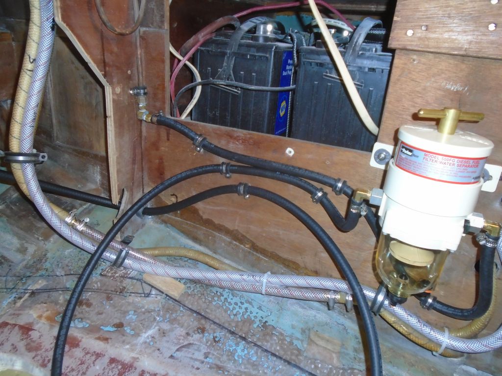
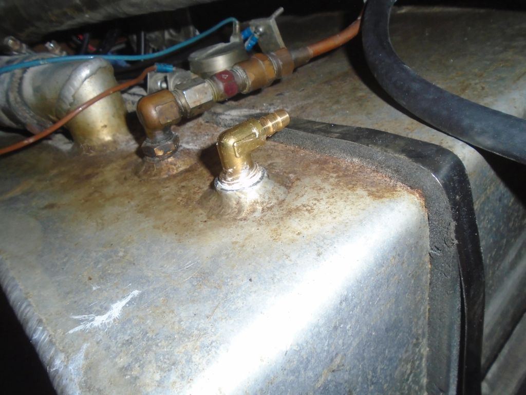
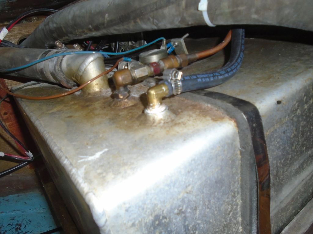
Continuing work on my diminishing list of pre-engine installation tasks, I worked on the fuel system. With the proper adapter for the original flare nut on the annealed copper fuel line now on hand, I connected an elbow and hose barb to direct the fuel supply line forward to the fuel filter inlet. I kept the original copper fuel line intact because it was in good condition, was carefully plumbed into a nice flush shutoff valve in the quarterberth, and there was no reason to make more work than necessary.
Next, I ran 5/16″ fuel hose from the new barb to the fuel filter, securing it along the way. I also ran a length from the filter outlet back towards where it would eventually connect to the engine, leaving some excess awaiting the final connection once the engine was installed. I also led aft an additional hose for the fuel return line, which I led into the after compartment through an existing hole lined with chafe guard.

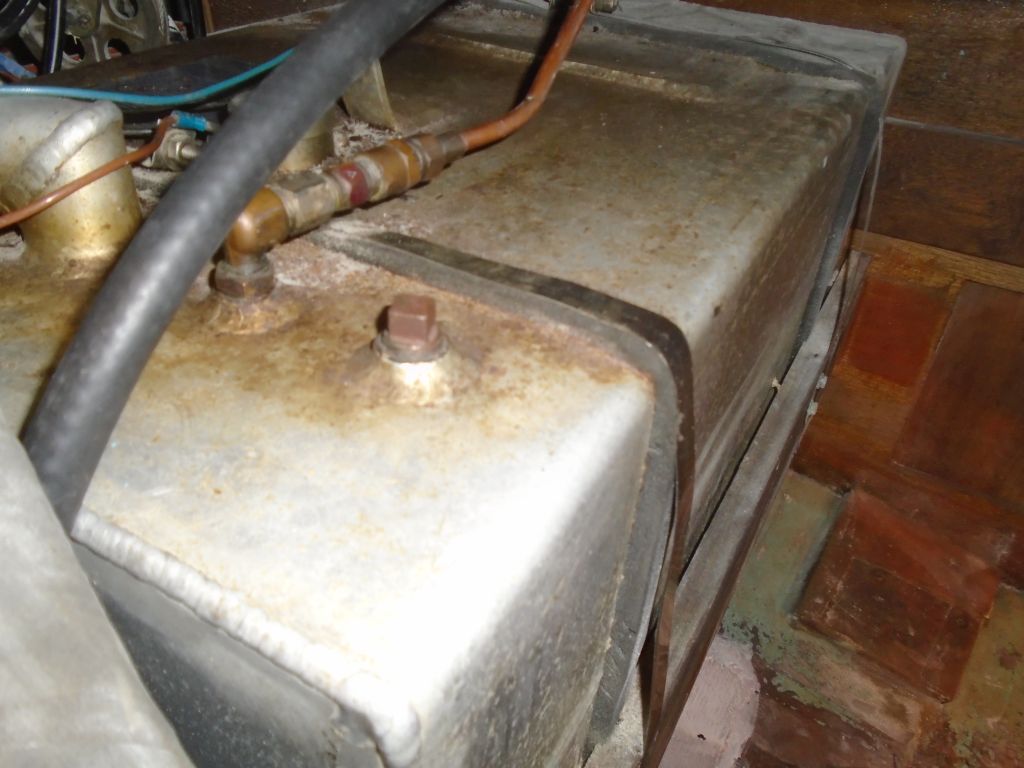
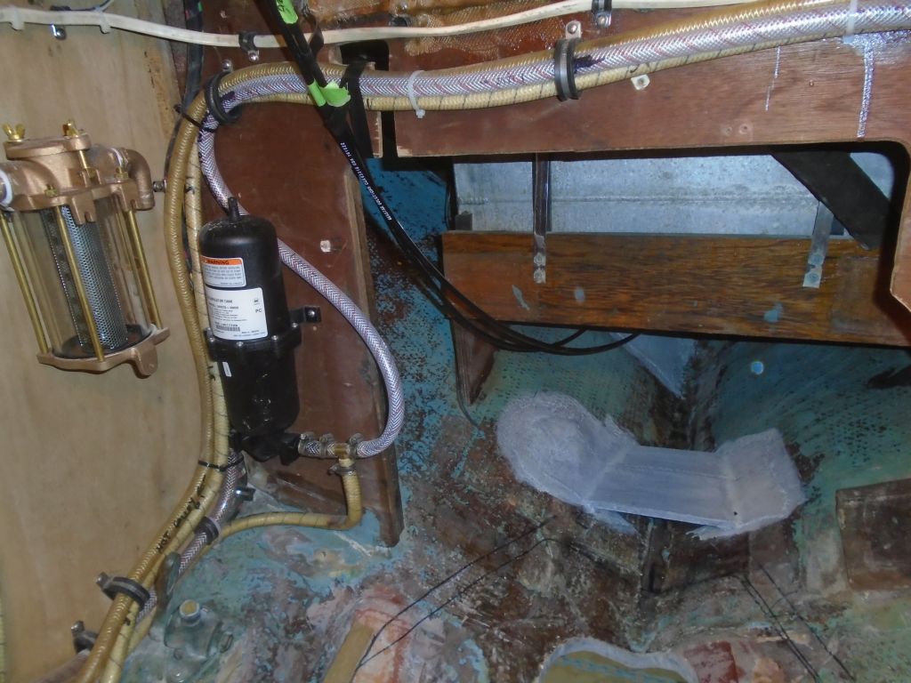
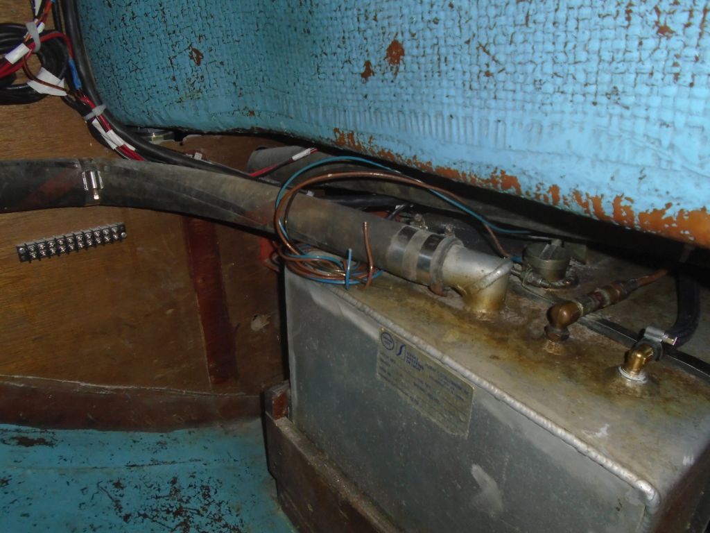
In the locker aft of the engine room, I secured the new return line (the old Volvo didn’t have a return fuel line leading to the tank) with rubber-lined clamps up the bulkhead, then alongside the copper supply line to the top of the tank. I replaced a blank plug on the tank with a 5/16″ elbow and hose barb to accept the new hose connection.


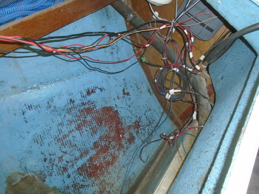
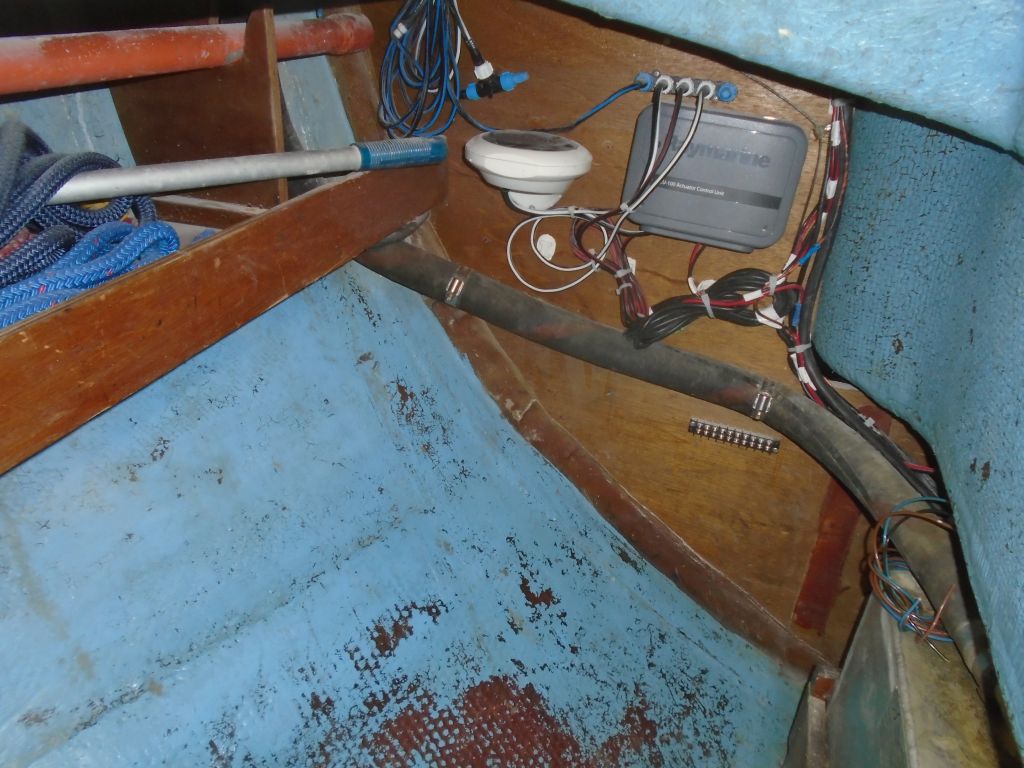
Earlier, while removing some obsolete wiring, I’d removed sundry failed wire tie mounts securing a wiring harness through the cockpit locker, leaving a mess behind. Now, I installed new wire tie mounts here and elsewhere in the immediate vicinity to allow me to resecure these wires, along with the new engine panel’s wiring harness (which I led aft to the panel and then forward into the engine room pending final connection). Getting them out of the way, I also led the new engine control cables forward beneath the fuel tank, securing them for hte mom ent to leave the hull space clear for imminent painting.

I also took the opportunity to separate an old taped-up wiring harness so I could pull free the wires leading to the fuel tank sender, which the owner reported had not been working. I had a new fuel gauge on hand, and hoped that new wires and the new gauge would take care of the problem. I wasn’t sure if removing the sending unit was possible with the tank in place, but I’d only go there if other efforts failed to succeed.
To round out the day, after final preparations I painted the section of the engine room beneath the fuel tank with a 50/50 blend of Bilgekote white and gray, stopping at the new muffler platform. Later, I’d paint the rest of the engine room, but not until the new foundation was tabbed in place.

Total time billed on this job today: 7 hours
0600 Weather Observation:
Mostly clear, 40°. Forecast for the day: sunny, 60s