October 7, 2016
Acadia 13
Friday
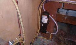
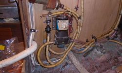
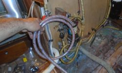
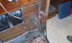
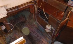
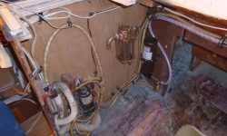
Continuing with the engine room preparatory work, I focused again–and first–on the fresh water plumbing, picking up where I left off. I added a new length of hose leading from one side of the tee fitting downstream of the new accumulator tank to eventually service the cold supply for a water heater. I led this, and the other pair of hoses, around the back end of the engine room and down to the port side, where the hoses fed into the cabinetry near the forward end of the engine room. I secured the hoses with rubber-lined clamps as needed to keep them safe and out of the way.
Near the pump, I found room for another tee fitting that was part of the original configuration, where the two tank supply lines conjoined, and, as required, I shortened and reconfigured these hoses to lead into the water pump suction side. I extended a hose leading from the port tank, exiting the cabinetry on that side of the engine room, but for now I left this length of hose unconnected pending the installation of the engine foundation, after which I’d know how and where to lead and secure the final length of hose.
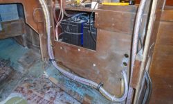
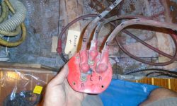
When I removed the old engine, I’d removed the original battery switch and its cables, which were in the way at the time. Now, the potential routing of these cables would have an impact on my chosen fuel filter location, near the head of the engine room to port. This might require releading or replacing the existing cables, so to start I marked and removed the three cables from the back of the switch, and reinstalled the switch in its original position. I’d route the cables back to the switch later, but their original routing left something to be desired and for now these cables were secondary to the requirements of the fuel system.
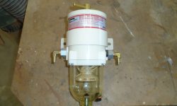
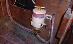
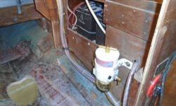
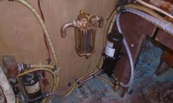
After preparing the new fuel filter–supplied by the owner with his engine purchase–with the appropriate fittings, I installed it on the blank cabinetry at the forward port side of the engine room where it’d be easily serviceable under any conditions. I left room above the filter to allow removal of the cartridge even when the overhead cabinetry and drawers were in place. Clearance between the filter and the engine would be tight-ish, but the footprint of the engine foundation was outside that of the filter, and according to the engine drawing the engine should remain inside the edge of the foundation here. Later, I’d connect the filter, using new hoses, with the existing length of copper tubing that remained at the aft side of the engine room. First, though, I required an adapter fitting to convert from the flared nut end of the tubing to a hose barb.
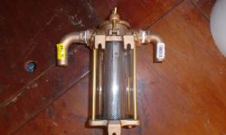
The final pre-installation in the space was the raw water filter, which I mounted on the starboard side directly above the raw water intake seacock. I’d connect its hose runs later.
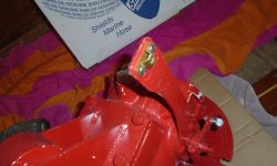
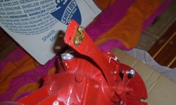
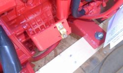
Engine control cables require fussy little clamps at the engine and transmission to hold the cable in place, and before installation I always liked to replace the irritating shallow-slotted screws and tiny metric nuts with 5/32 Allen-head bolts and #10 nuts for ease of installation in dark and tight confines typical of most engine rooms. One likes to remove unnecessary frustrations wherever possible.
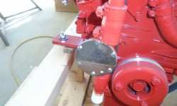
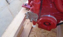
Similarly, I always replace the tiny original screws holding on the raw water impeller cover plate, choosing instead large knurled fasteners for ease of use. When the pump impeller fails underway, the last thing one needs is a slotted screwdriver and minuscule screws standing between quick replacement of the impeller. Easy fasteners promote sound maintenance practices too, for annual inspection and replacement of the impeller.
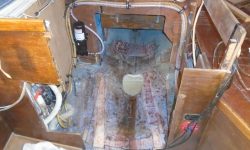
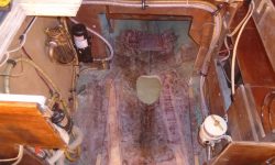
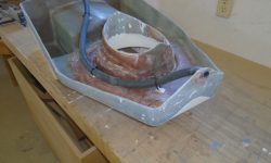
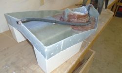
The epoxy securing the limber hose I installed through the base of the engine foundation was cured, and I cut off the excess hose length as needed.
Total time billed on this job today: 3.25 hours
0600 Weather Observation:
42°, clear. Forecast for the day: Sunny, near 80


