

November 30, 2018
Dharma Rose 6
Friday
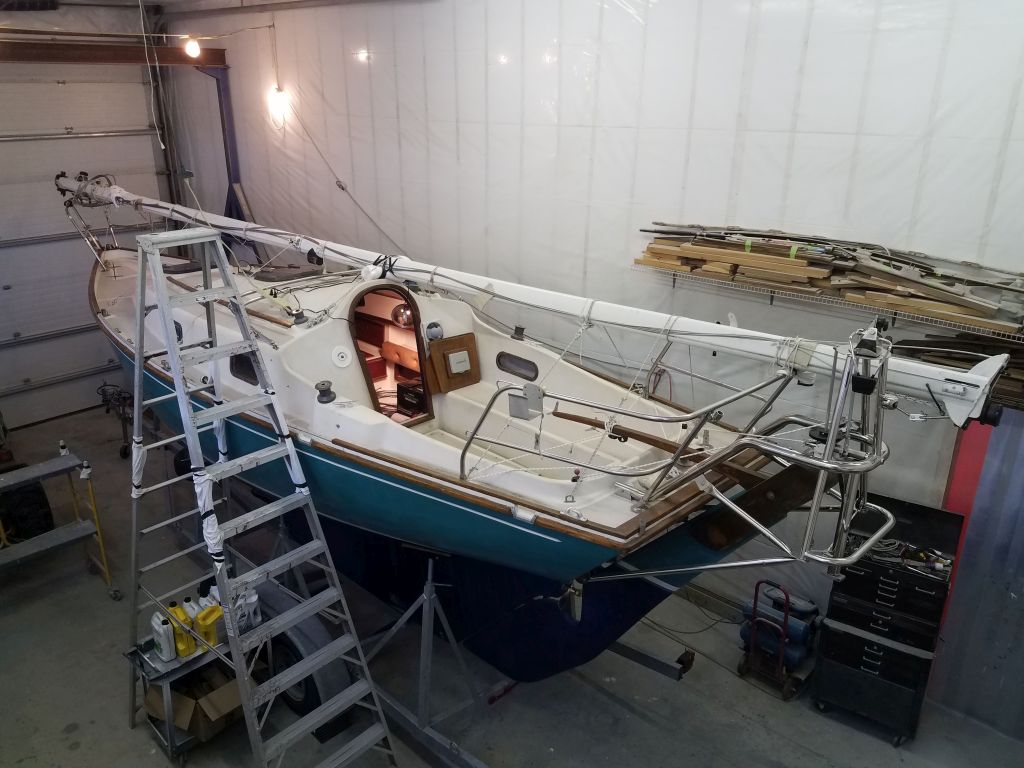
I had a short day planned, but wanted to make good progress in the engine room first. I planned to build the new engine foundations from 3/4″ G10 composite sheeting, an almost foolishly strong and hard fiberglass and epoxy product that’s overkill for almost every proposed situation, but provides the durability and piece of mind one might consider useful in something like an engine bed. G10 is also heavy and difficult to work, and therefore machining tasks are best kept to a minimum.
To template the position and shape, of the new foundation pieces, as well as continue to check the overall engine alignment and proposed placement accurately, I chose to build basic mockups of the foundations from some scrap pine lumber that was light as a feather after more than 12 years aging in my shop, and easy to work to boot.
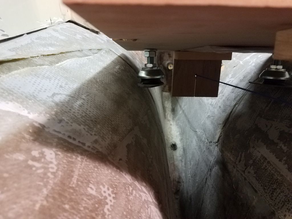
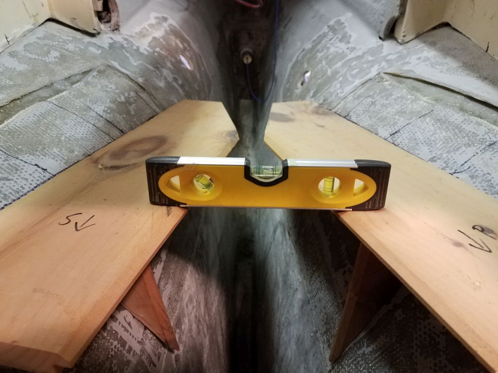
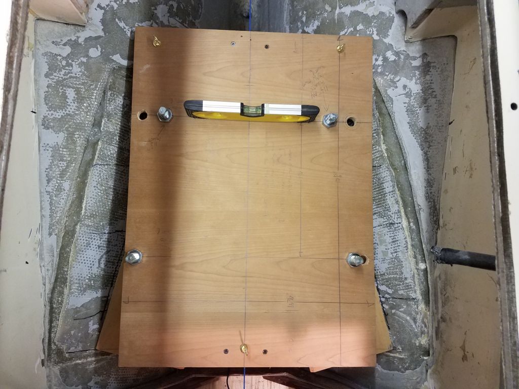
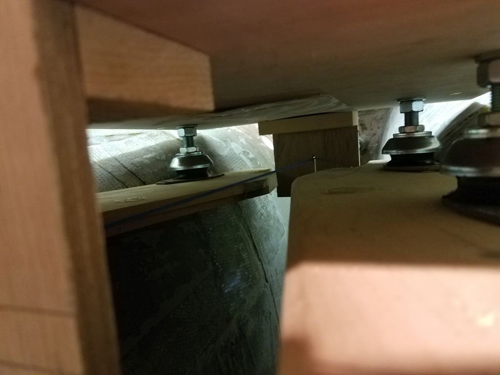
With the engine template suspended in the engine room over the taut shaft alignment string, I fine-tuned the position as needed, getting it as level and accurate as possible. Because of the suspension’s propensity to sway the whole template a bit aft, I used a handy bitter end of string to pull the template forward to my desired position, and checked and adjusted again till the template, still level, allowed the string to pass through the centers of the forward and aft template holes.
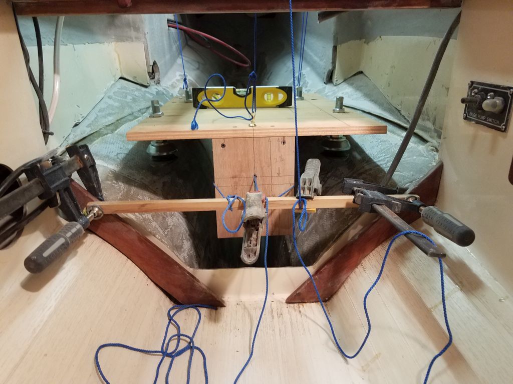
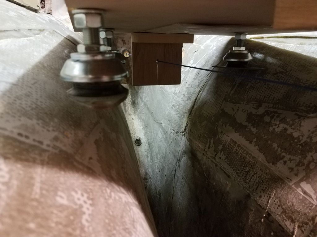
To help with basic positioning throughout the process, I used a metal straightedge to transfer and make reference marks from the centers of the mounting studs to the sides of the engine compartment. Then, with a small steel rule held tightly to the bottoms of the forward mounts, I transferred their heights to the hull side, making tick marks on each side. I re-checked the level each time, since the whole template was easily knocked out of position in its dangling lines.

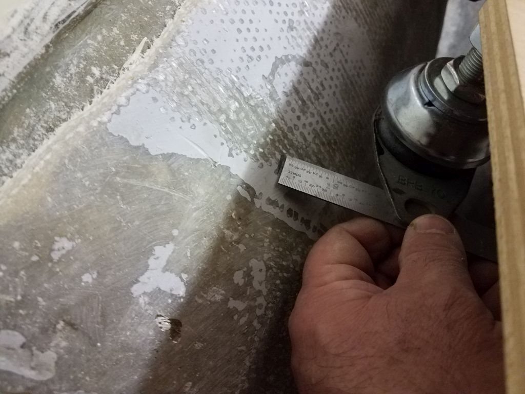

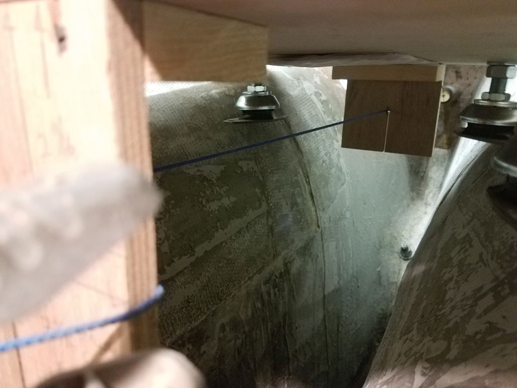
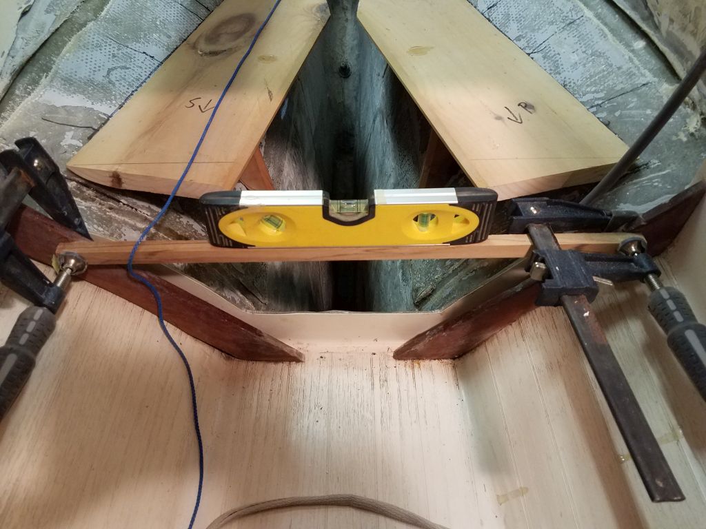
The tight confines of the compartment and the way the engine template hung over the curvature of the hull prohibited clear access to the after mounts, so to help mark their position I first removed the two forward mounts, re-checked level and position, then managed to get some rough marks aft where the mounts contacted the hull. I couldn’t manipulate the little ruler and pencil like I did forward, but in this case the after mounting bases just touched the hull at their outboard sides, which was enough for me to get reference marks that would serve the required purpose.

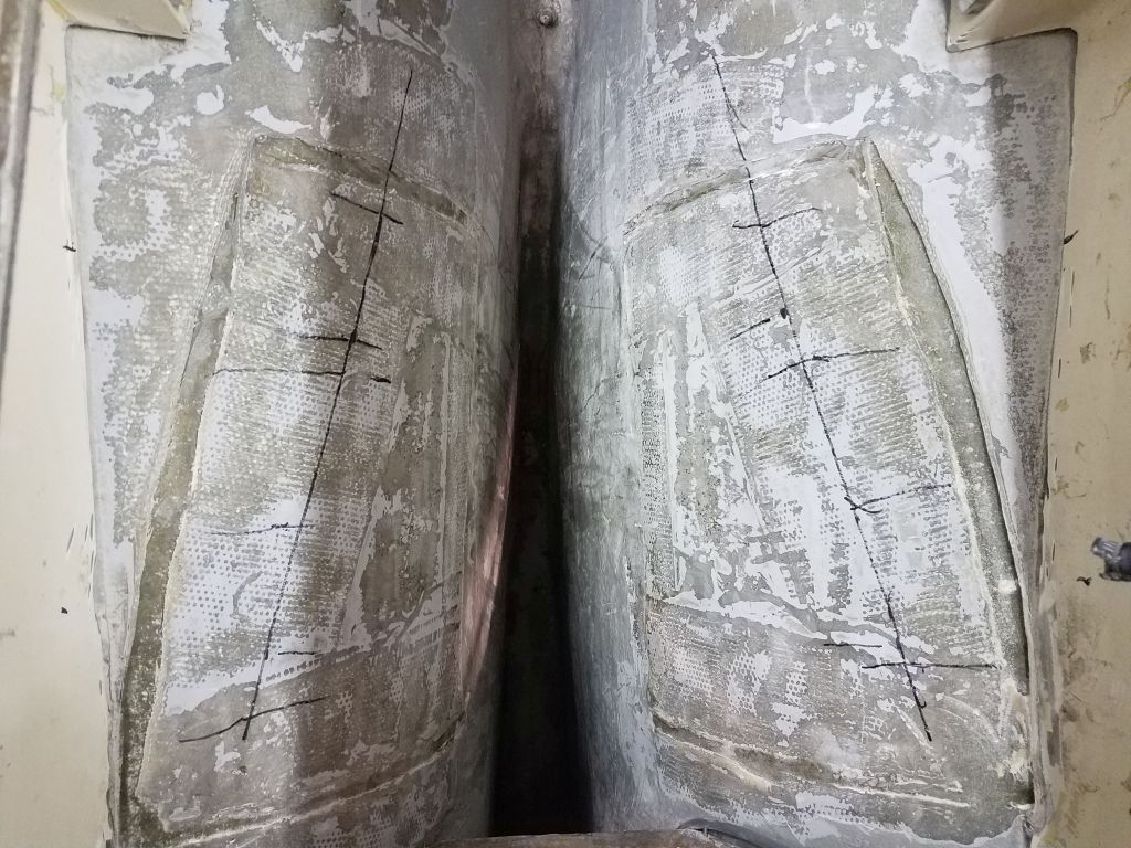
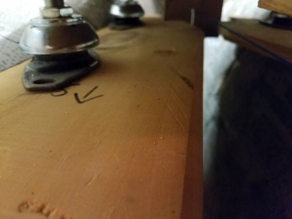
Once I had all four mounts’ locations marked, I removed the template and string for now to open up access to the space, and darkened the four tick marks with a pen before connecting them on each side with a flexible steel rule; the lines turned out more or less straight since the hull curvature here was transverse more than longitudinal. These lines gave me the reference for where the flat engine foundations needed to be. To help with overall dimensioning, I made rough marks to correspond with the flex mounts’ positions and lengths on each side. I didn’t want the new foundations to be any longer than strictly necessary, to aid all future access to the engine and the space, but also needed to account for some necessary wiggle room to allow the engine to be properly positioned fore and aft as dictated by the vagaries of the installation when the time came.

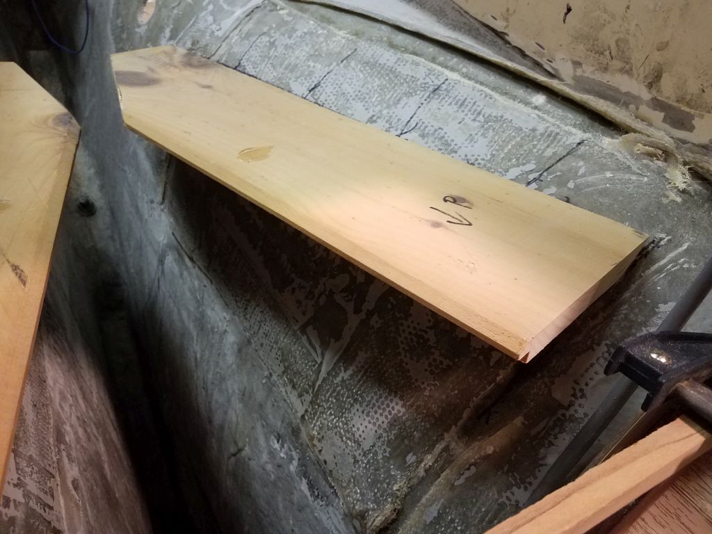
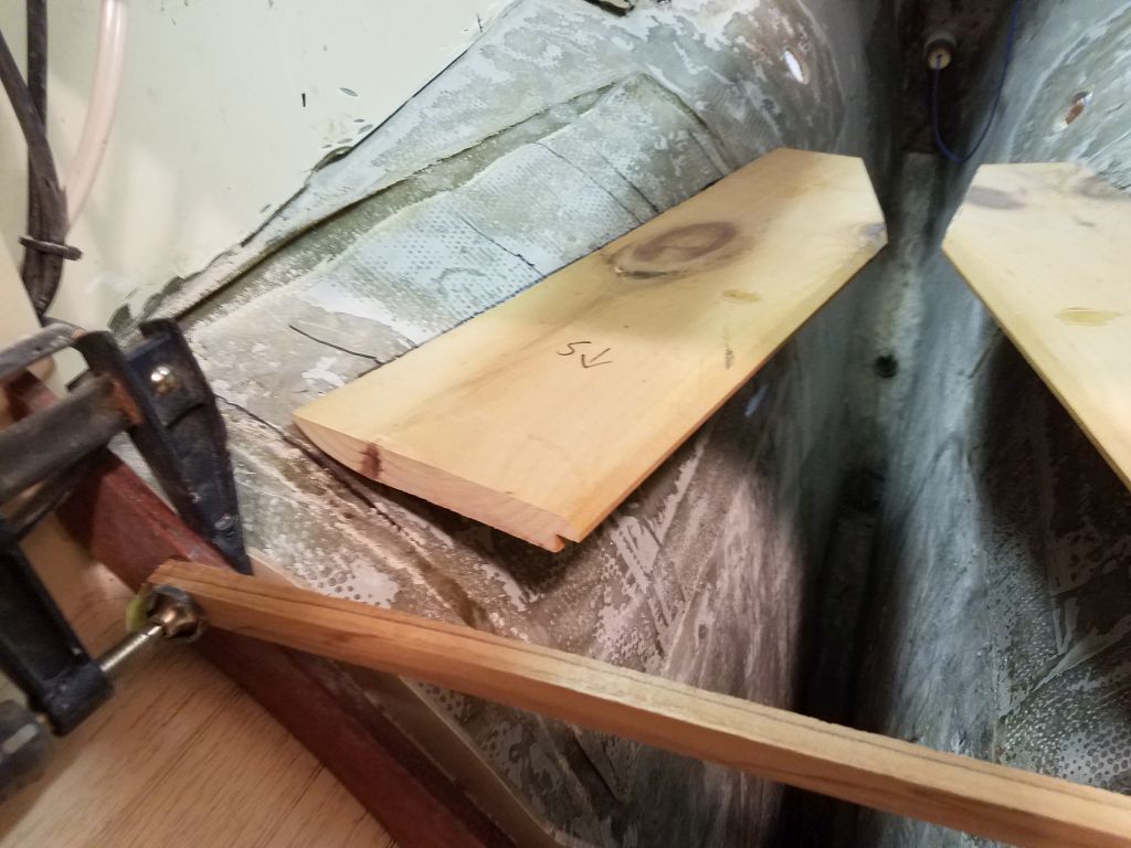
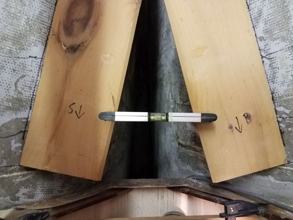
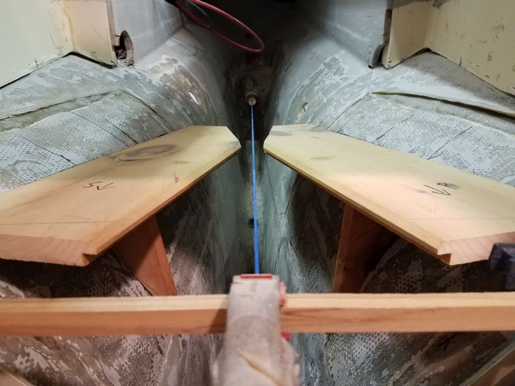
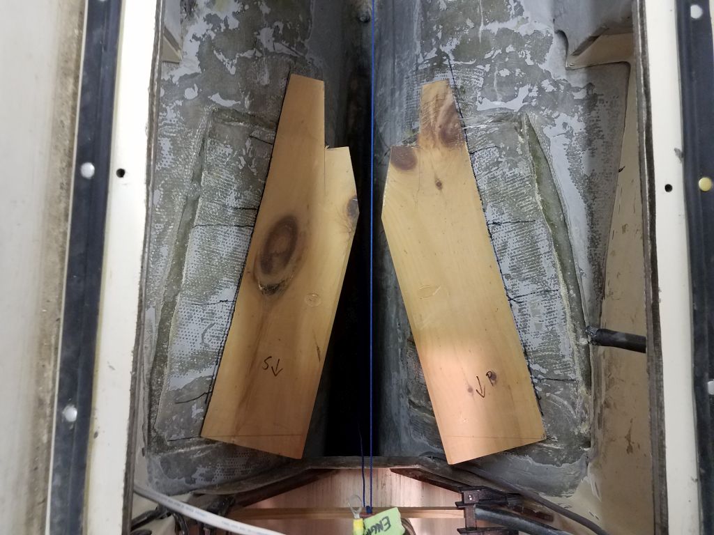
From scrap pine board, I made two pieces 24″ long and whatever its width was (about 6″). The width at this stage was unimportant, and the length was just a starting point; similarly, the inelegant ends would eventually be massaged into something more situationally- and aesthetically appropriate. I cut as steep a bevel on the outboard side of each piece as possible, and knocked off the after corners of each board so that the two sides together wouldn’t interfere with one another. After a couple brief test fits and some minor reshaping with a sander to allow the templates to fit more or less closely against the hull on each side, I tacked them in place with some hot glue along the lines I’d marked earlier, striving to force them level in the process.
The starboard forward end ended up a bit higher than I’d planned, accounting for the slight off-ness [sic] of the level, but that didn’t matter for these purposes, as my goal, other than checking the basic positioning for later, was just to provide simple templates from which I could more easily and efficiently shape the granite-like G10 material later, and the minor discrepancy didn’t affect the shape of the mockups (nor of the final fiberglass) at all. The time for ultimate accuracy would be during the final and permanent installation later.
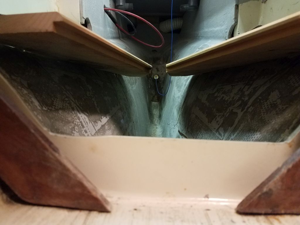

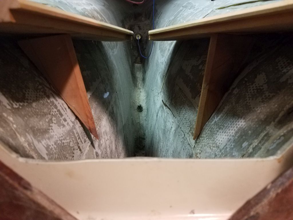
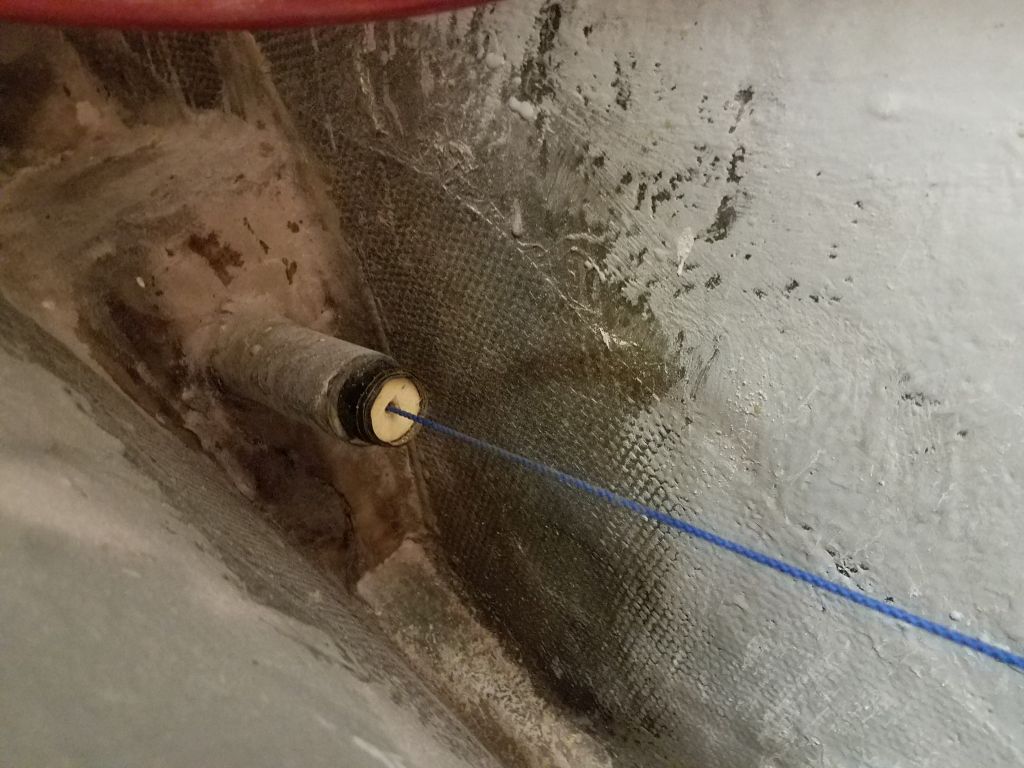
With the rough cutting complete, and the boards tacked in place, I glued the little triangular offcuts from the aft end beneath each side to help support the boards from beneath, again holding the inboard edges of the board level while I did so. Afterwards, I restrung the alignment string from the shaft, this time working just a little harder to ensure its accuracy.

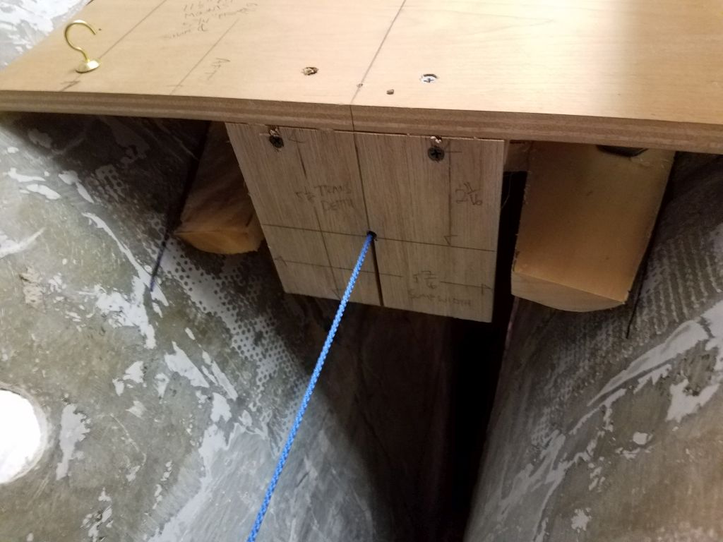
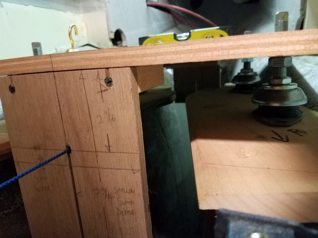
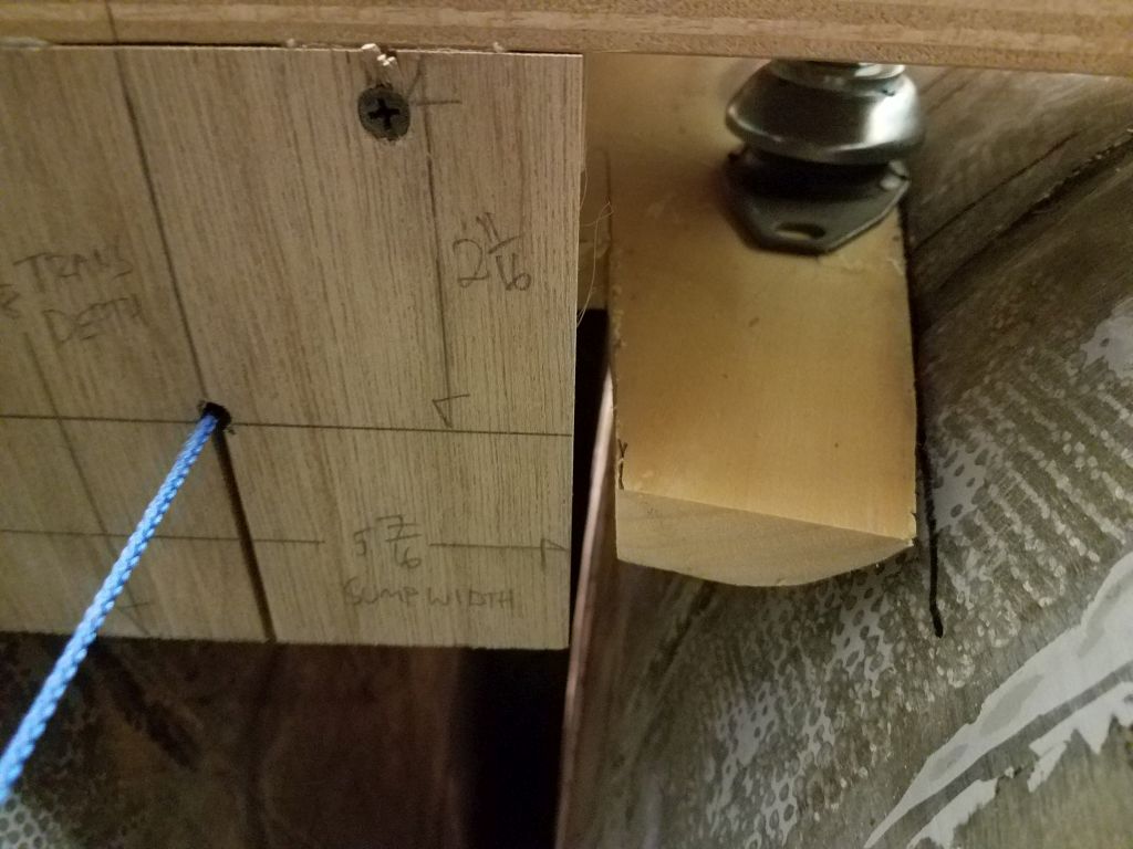
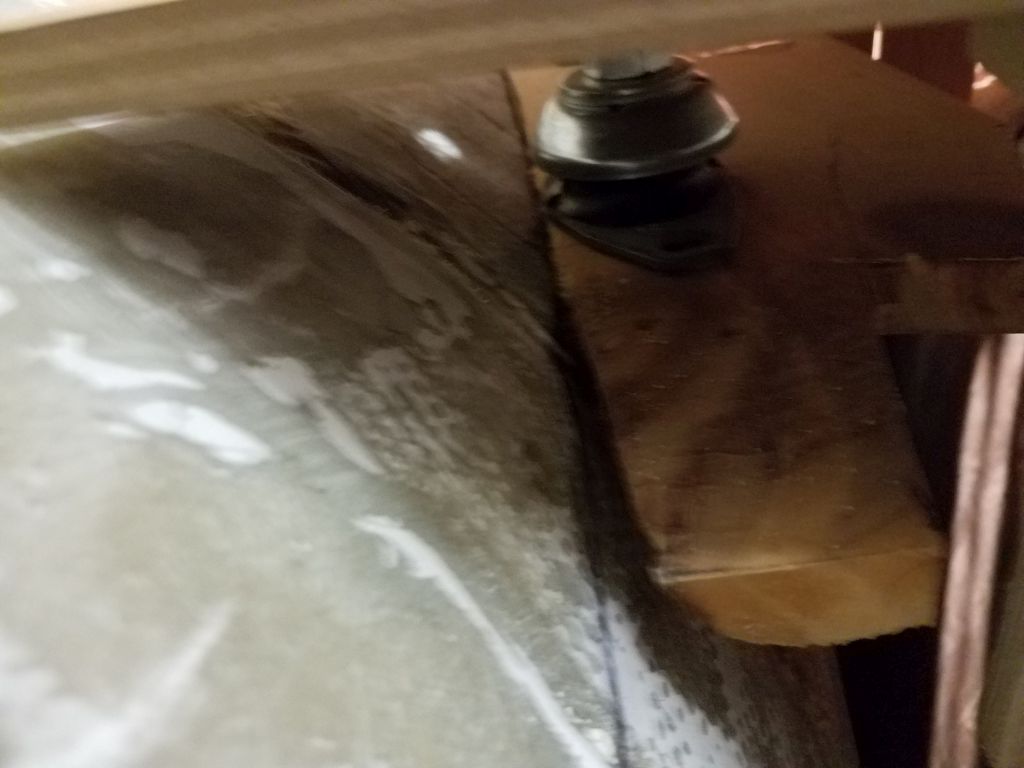
Test-fitting the engine template again, I immediately saw that I needed to provide clearance at the aft end for the down-hanging plywood board that provided the shaft centerline mark (and also happened to correspond to the transmission width and depth for this engine), so I carefully cut out some extra material with a handsaw to allow a proper fit. Then, I installed the template and made whatever adjustments were necessary to properly position it.


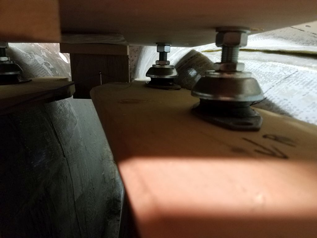
I was pleased to see that the engine fit well on the mockup foundation, particularly at the difficult and tight after end. I was running out of time in my self-shortened day, but before knocking off I made reference marks as much as possible to show the positions of the four flex mounts; again, reaching the after mounts was virtually impossible given the shape of the template–which, we must not forget, represents the overall size of the largest dimensions of the engine and transmission together, and is not necessarily representative of the actual shape thereof–but I managed to get some scribble marks in there that would be enough to allow me to determine where to mark and cut the foundation mockups to their final desired shape next time.


Total time billed on this job today: 3 hours
0600 Weather Observation: 25°, mostly clear. Forecast for the day: Mainly sunny, 40°