

December 18, 2018
Dharma Rose 18
Tuesday
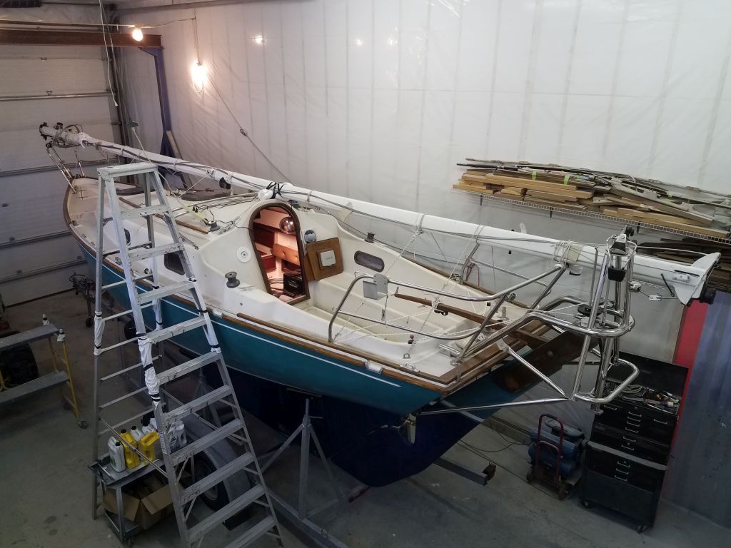
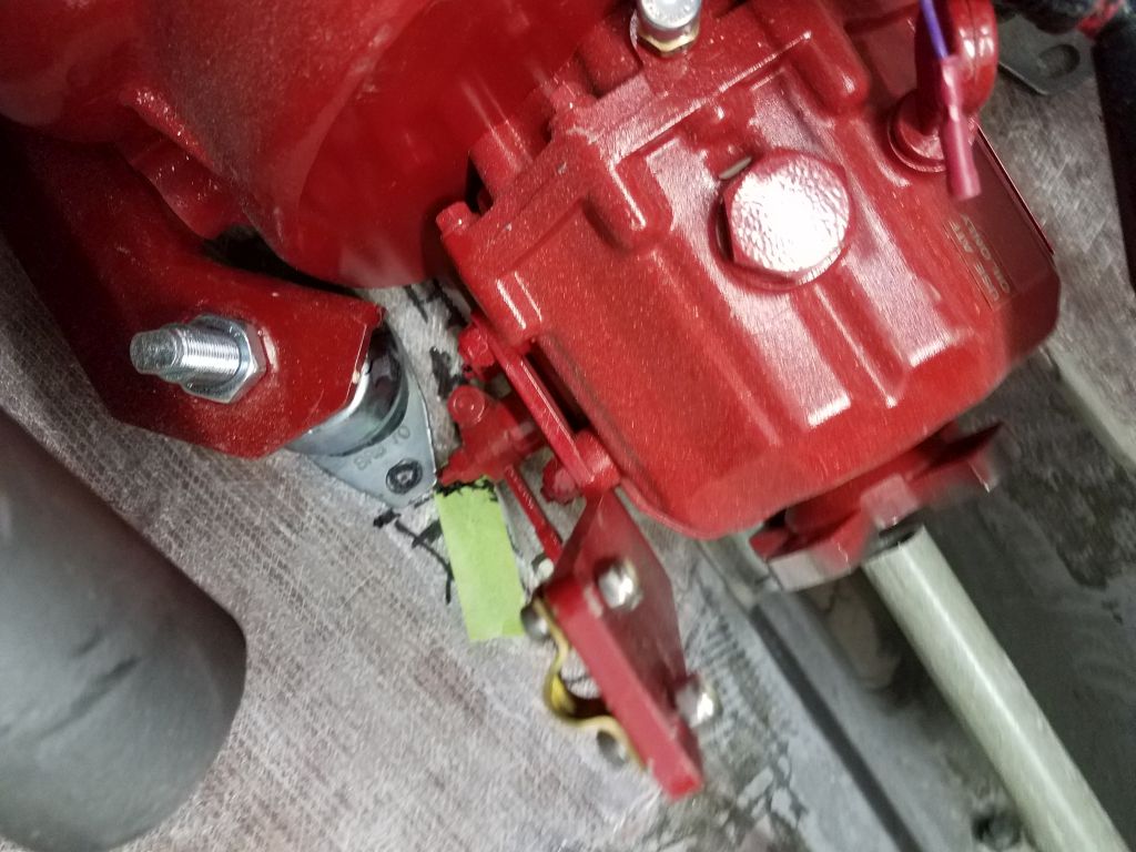
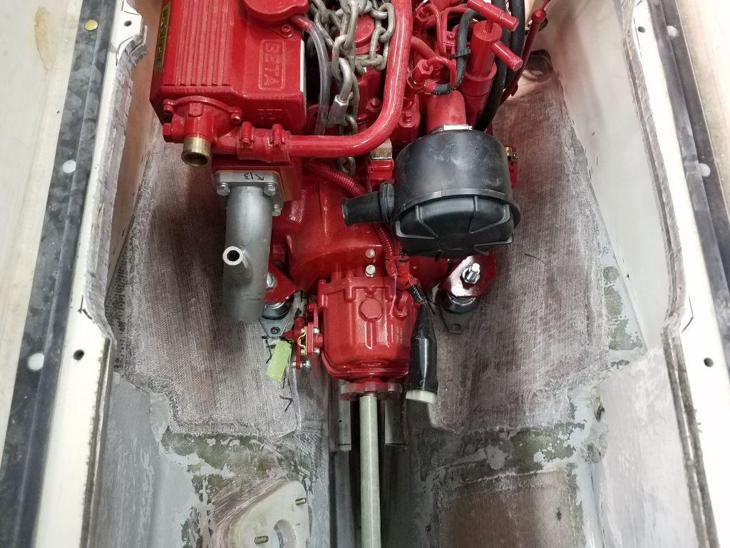
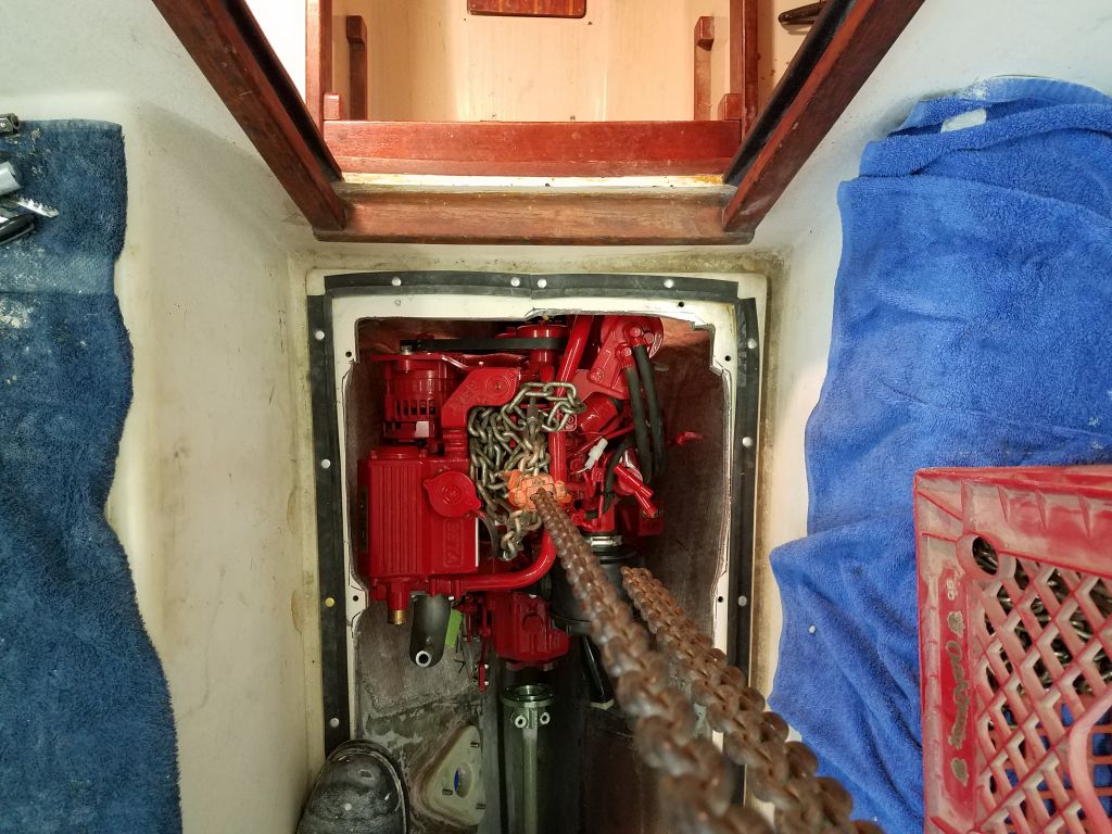
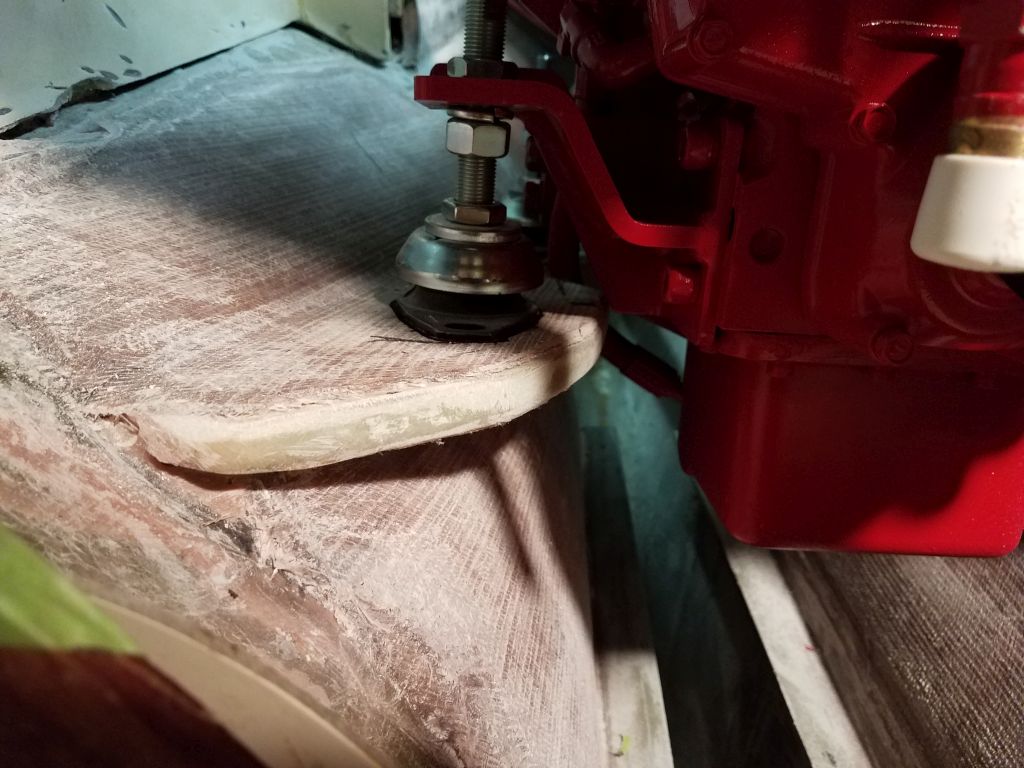
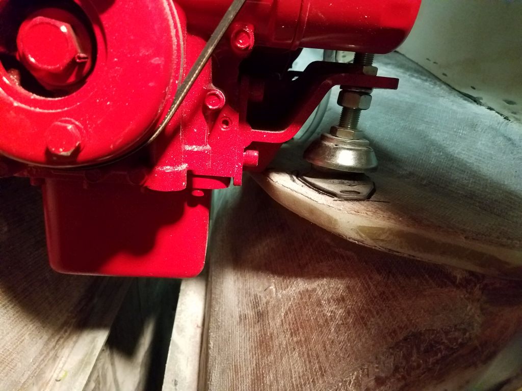
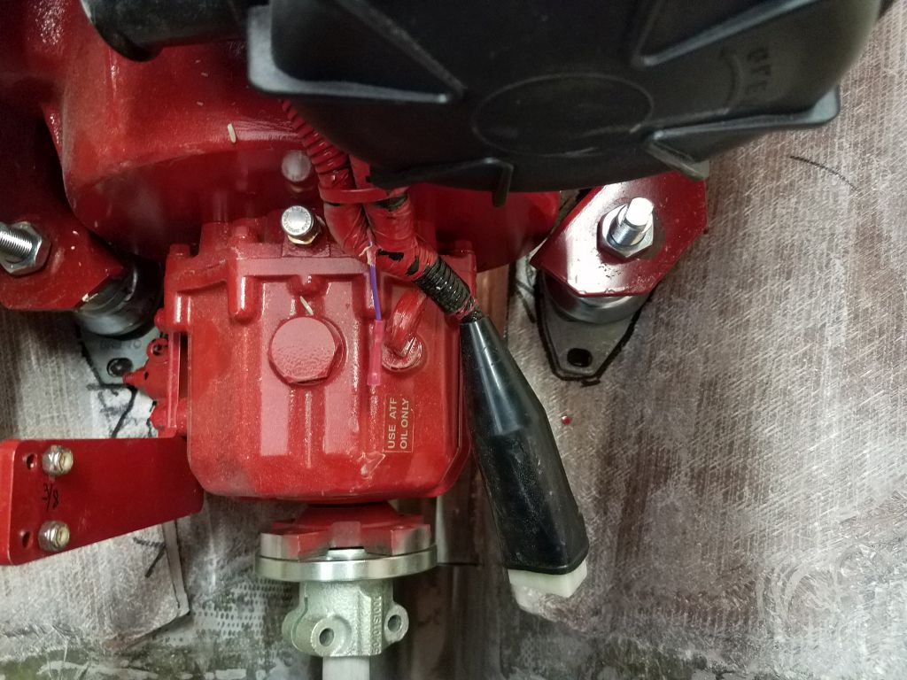
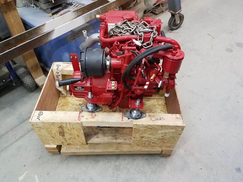
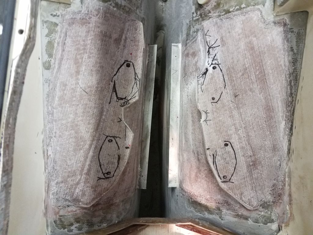
With the engine still in place on the foundations after resting overnight, I made some final reference marks to determine where I needed additional cuts, mainly at the port aft end to improve clearance for the transmission shift lever. Then, I removed the engine so I could make the cuts, before lowering the engine once again and repositioning it on the foundations.
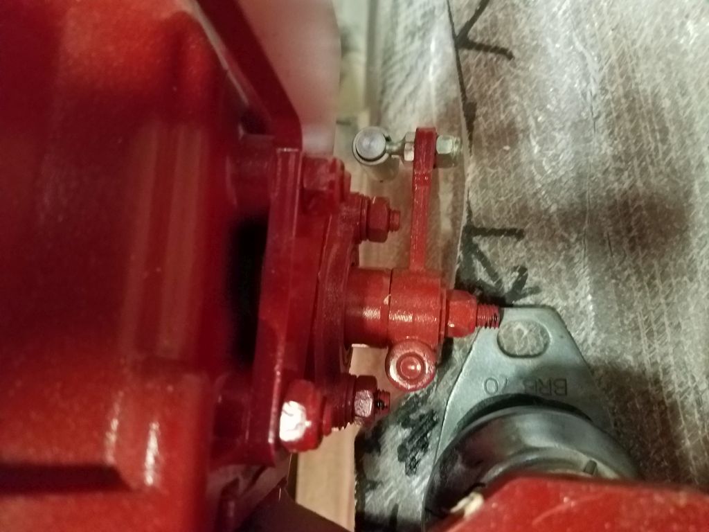
The new cut at the aft end helped, but I found that I’d need to open up the cutout a bit at the forward end to allow full operation of the lever, so I noted the changes . For now, the engine was sitting properly enough on the foundations that I could move on with some of the immediately-related work that I wanted to accomplish now.
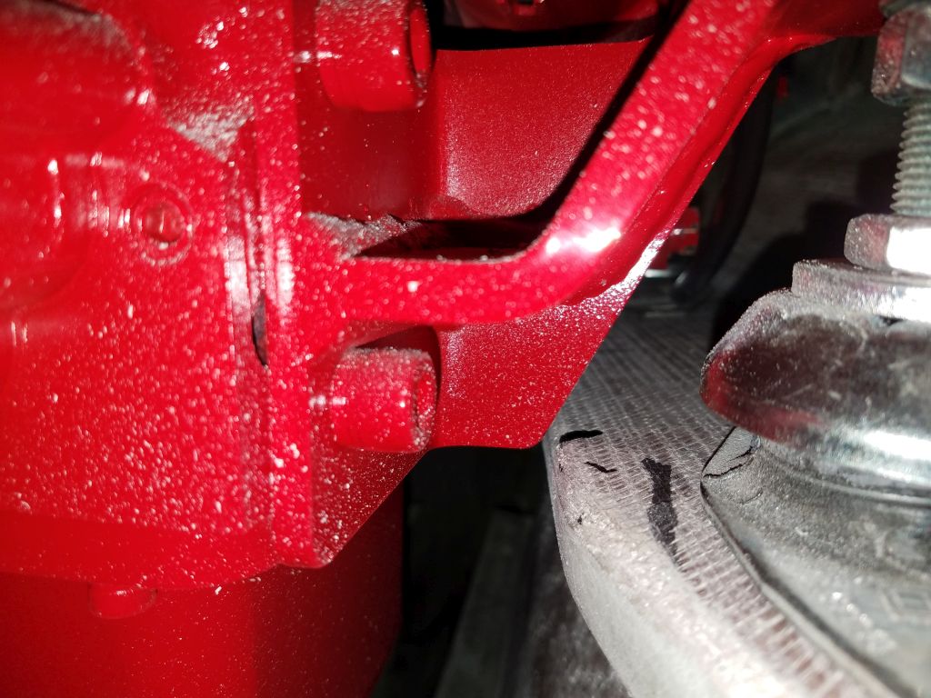
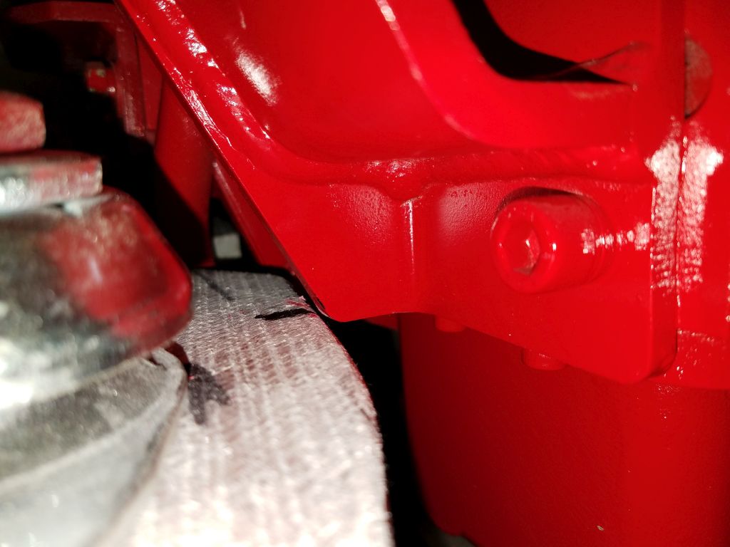
Part of the engine block came within a whisker of contacting the edge of the foundations just aft of the forward mounts, so I made some marks there so I could slightly open the area later, once I’d removed the engine again.
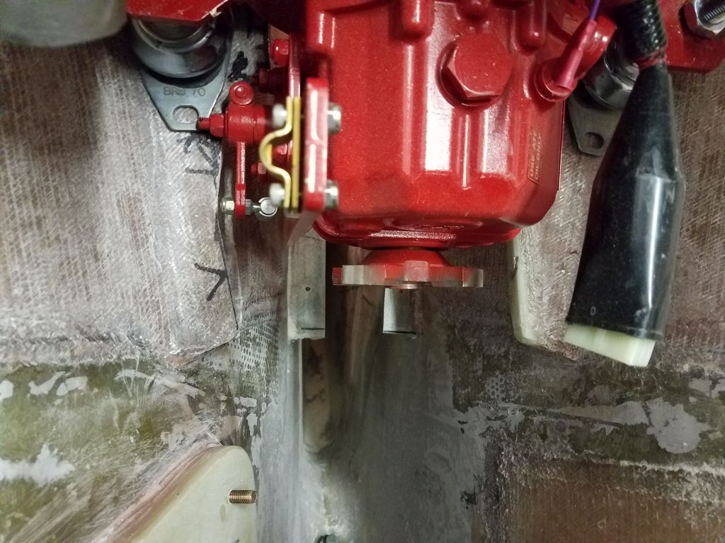
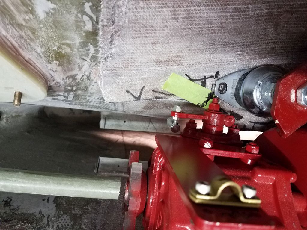
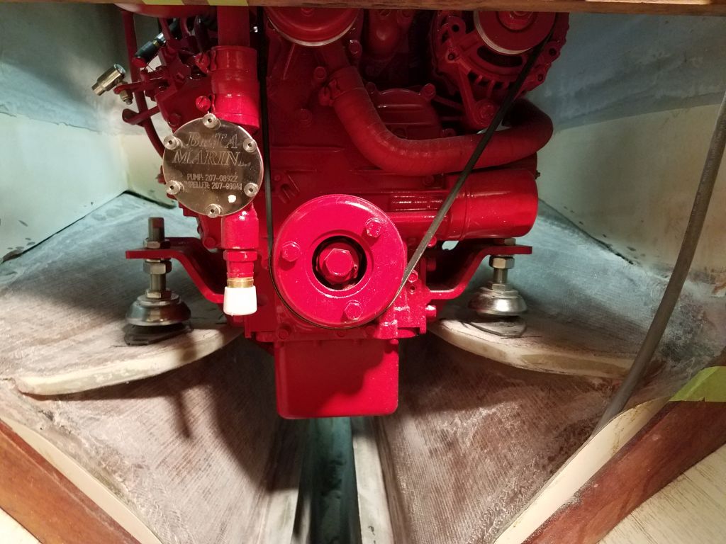
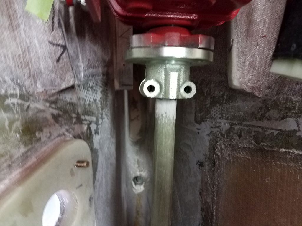
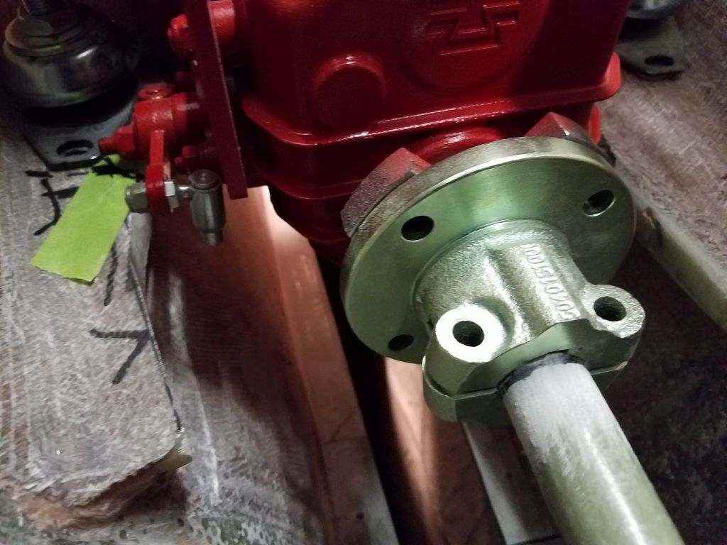
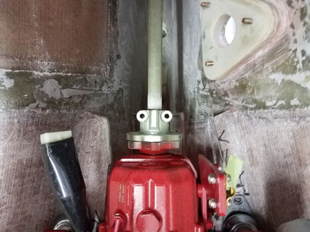
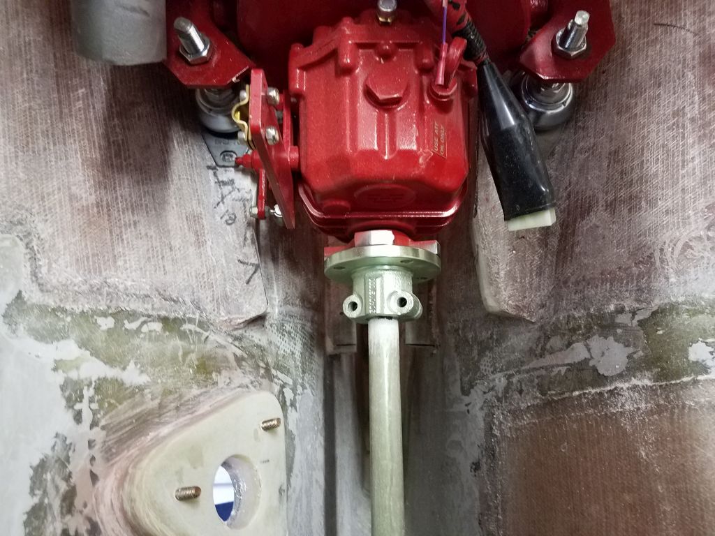
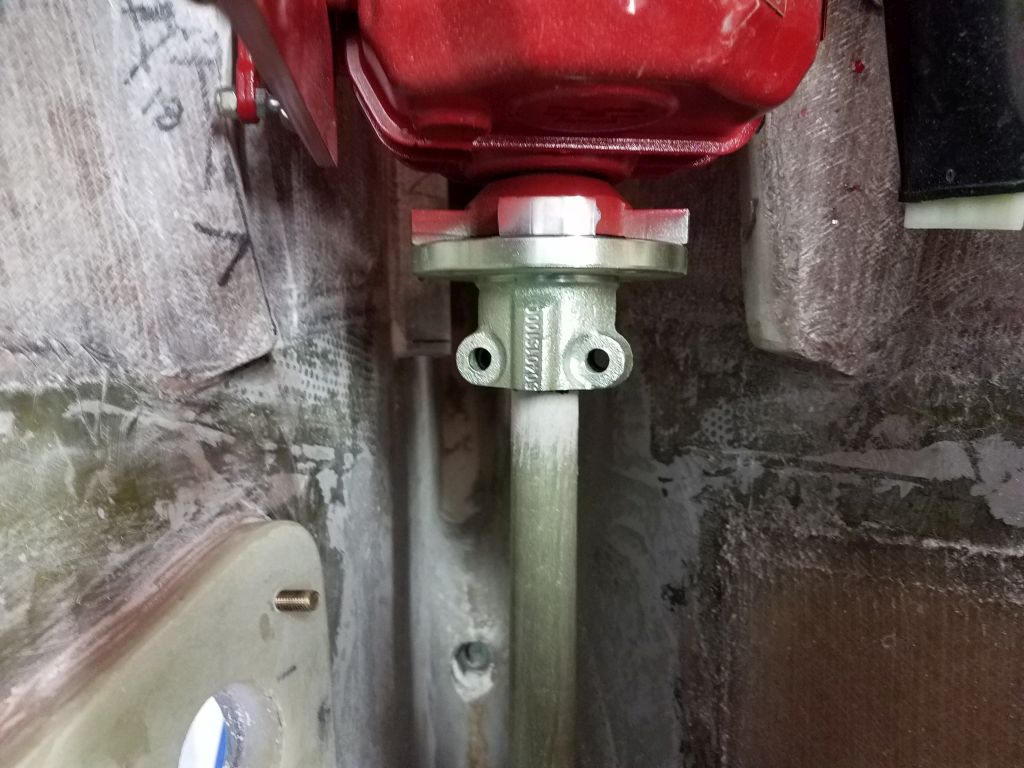
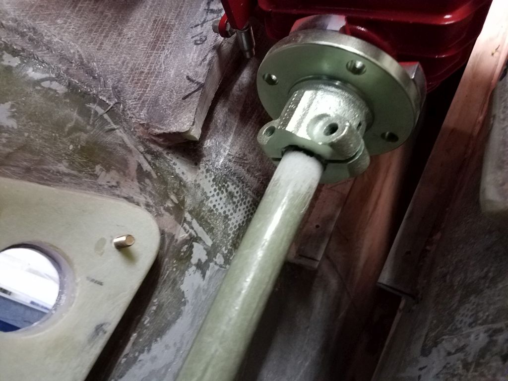
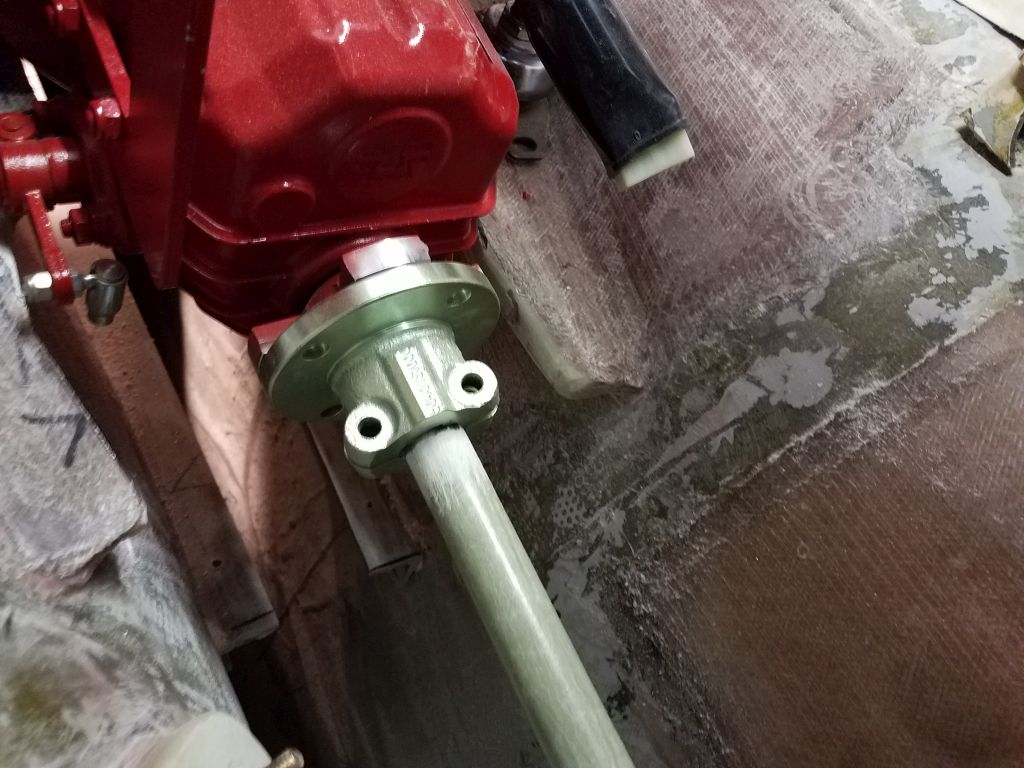
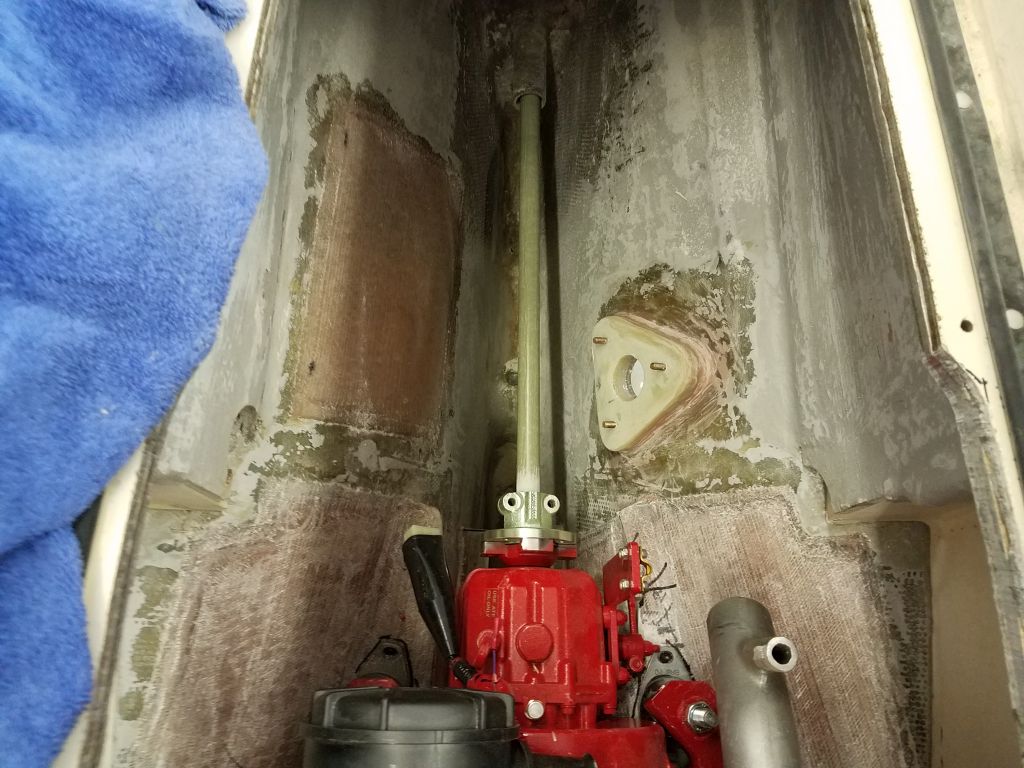
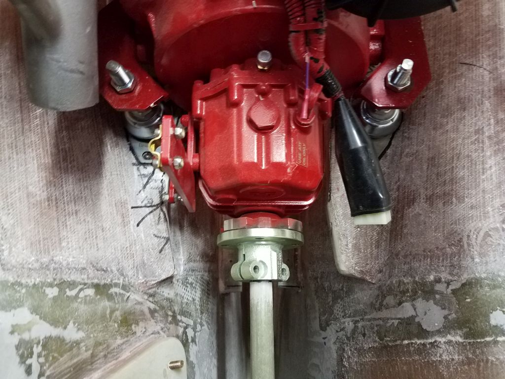
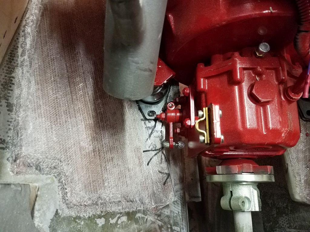
Using the stand-in propeller shaft as a guide, I joggled the engine around a bit to get it positioned generally in the right spot so that the shaft lined up with the center of the transmission coupling.
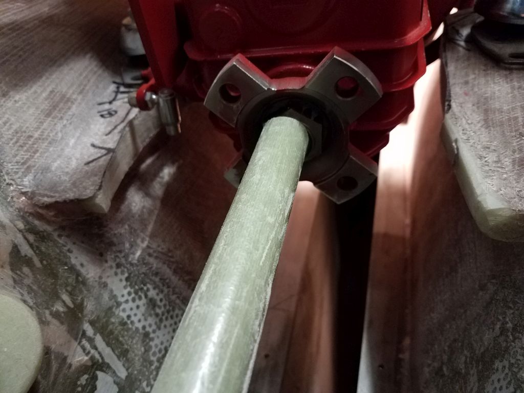
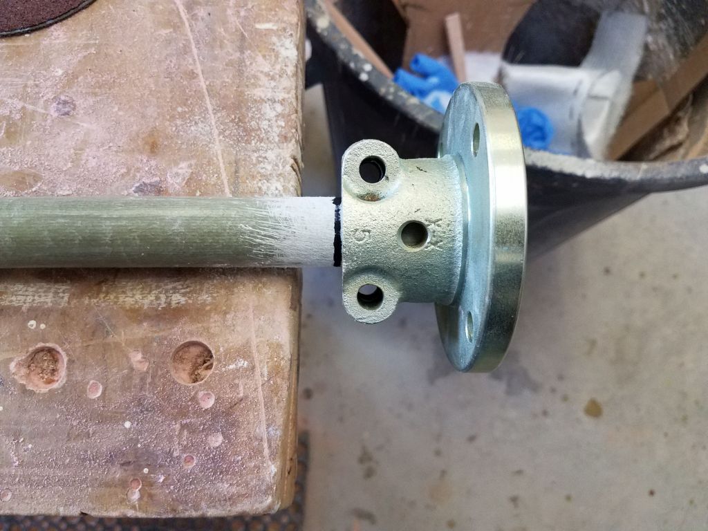
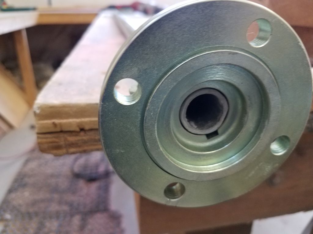
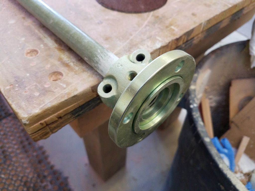
To get a better sense of the rough engine alignment, as well as measure the final length of the propeller shaft, I temporarily installed the shaft coupling on the end of the fiberglass shaft, which required a bit of sanding so it would fit. With the coupling in place and the shaft back in the boat, I lined it up with the transmission, and while the initial line-up was pretty good, the coupling faces were slightly off on one side, so I made some adjustments to the engine’s transverse and longitudinal positions, and slightly to the height of the aft mounts, which brought the coupling faces more tightly together, good enough that I felt like I could start to mark the shaft length, as well as the engine mount locations on the foundation.
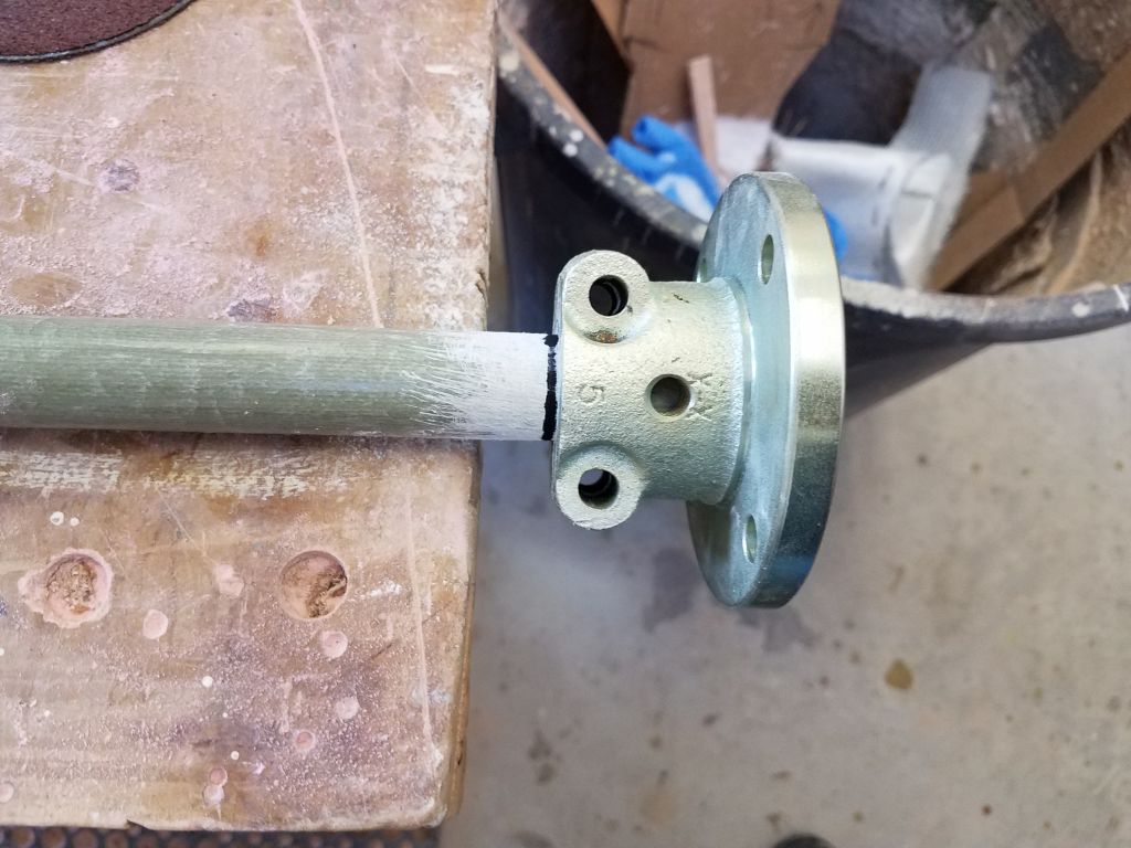

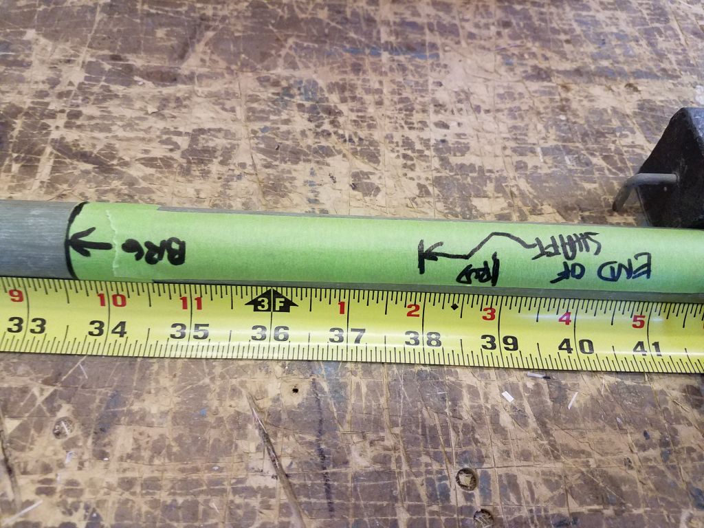
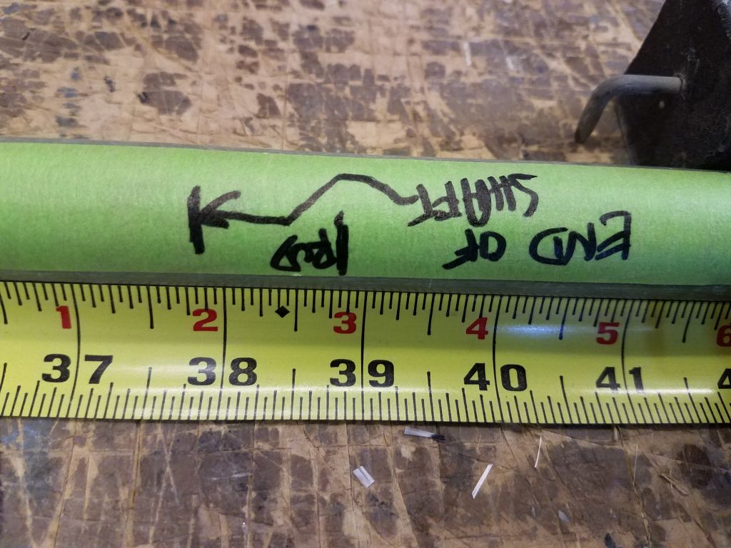
After double-checking the shaft position in the coupling, and ensuring that the coupling was properly placed vis-a-vis the transmission coupling, I went outside to mark the shaft where it exited the Cutless bearing, and used my notes from the original setup to mark the end of the shaft 4-1/2″ aft of the stern tube, leaving about 1″ clearance forward of the rudder, as before.
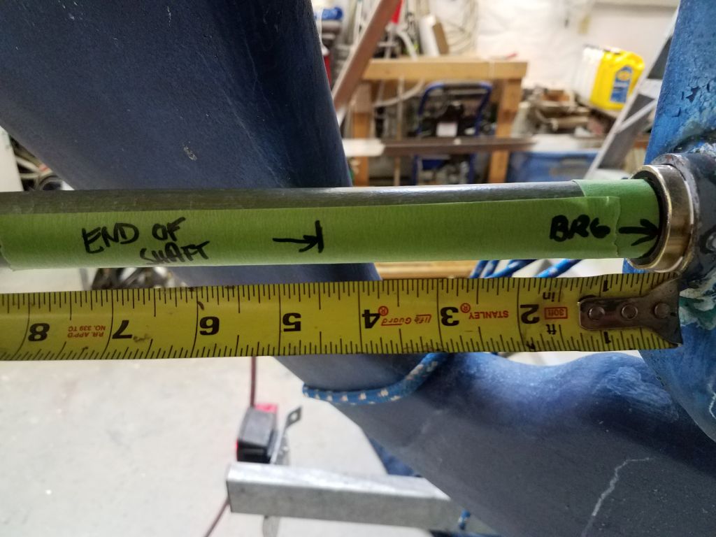
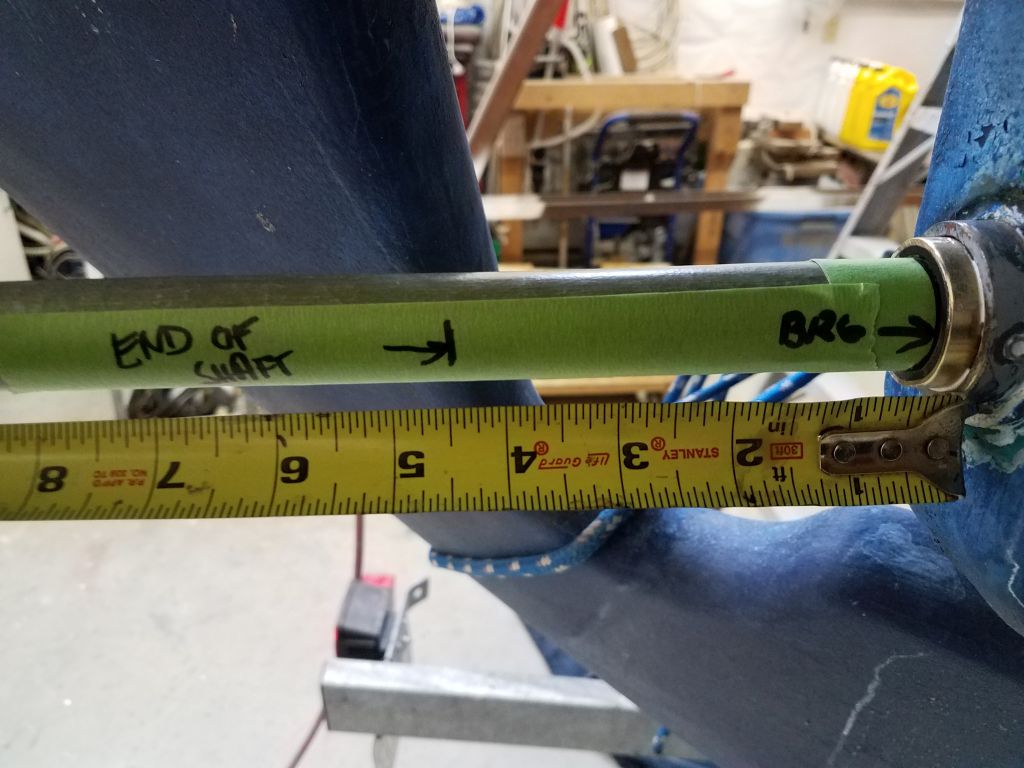
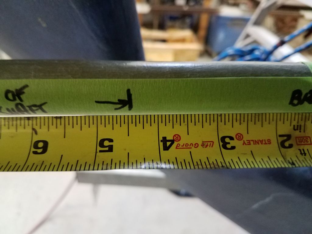

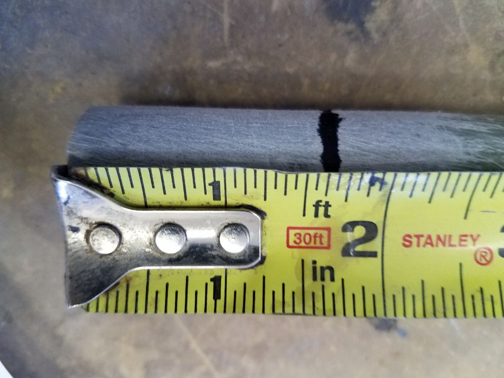
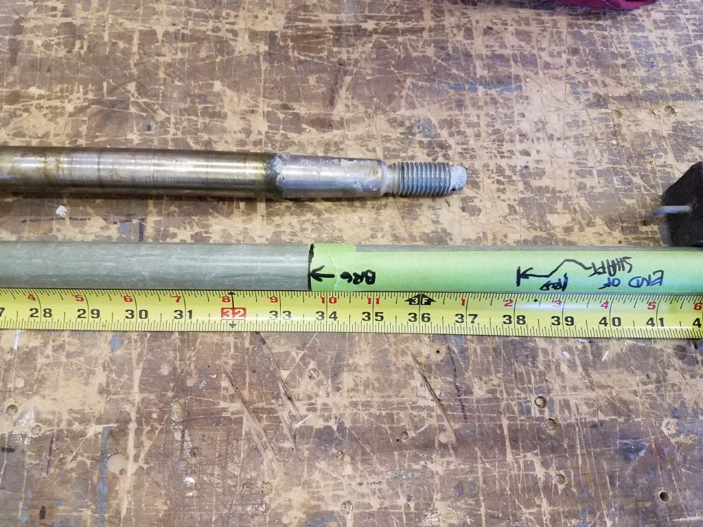
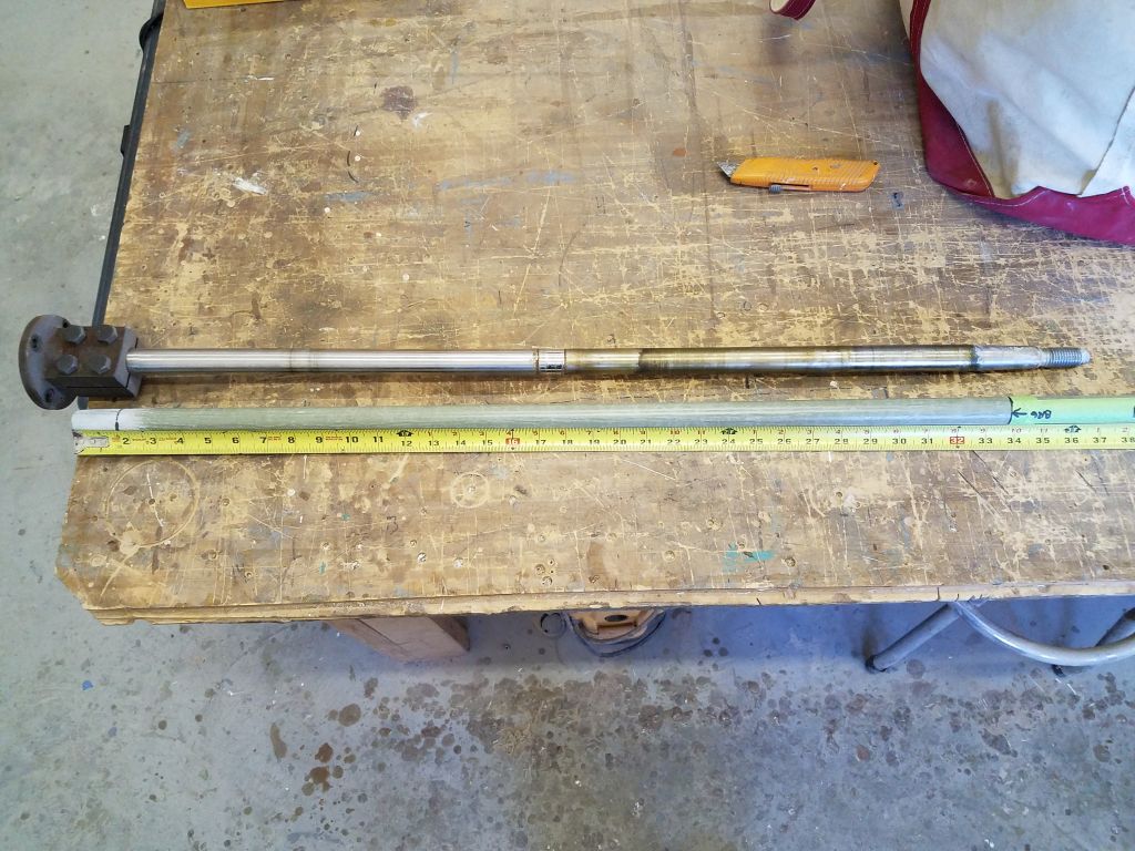
Now I could remove the shaft and make the final measurements so I could order the new shaft soon. The actual shaft length in this form came to 37-7/8″, and I’d need to make an allowance for the thickness of the flexible coupling that I’d install between the shaft and transmission couplings during the final installation. I held the old shaft against the new mockup just as a reality check; if something was far off, I’d check the measurements again. As expected, though, the lengths were close, but slightly different thanks to different engine lengths and positions.
This completed the initial round of engine fitting, and I removed the engine back down to the shop floor for storage till I was ready for the final installation.
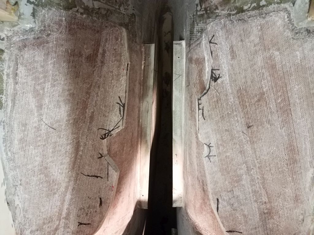
Next, I used sanders to clean up and smooth over the various cuts I’d made in the engine foundations and around the engine hatch, and to further massage the cuts around the transmission lever, where I’d made additional marks to enlarge the cutout. I used a small drill bit just to mark the centers of the engine mount holes that I’d marked, so that these locations would survive through the final engine room painting. I didn’t want to drill the final bolt holes till I was positive of the engine position later.
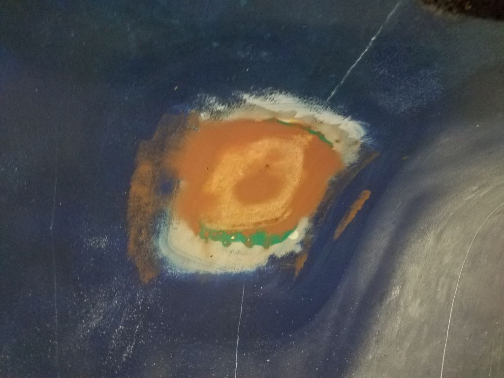
While I was at it, I lightly sanded the patches (inside and out) over the starboard scupper through hull, as well as the new floor in the battery compartment in the cabin.

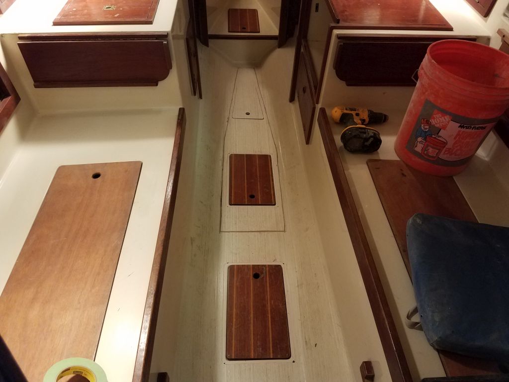
Meanwhile, inside the boat I unclamped the cabin sole and cleaned up all the masking tape, completing the work there for all intents and purposes.
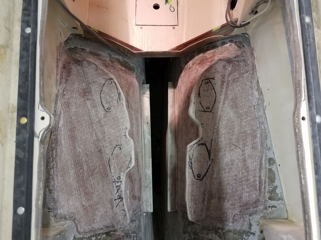
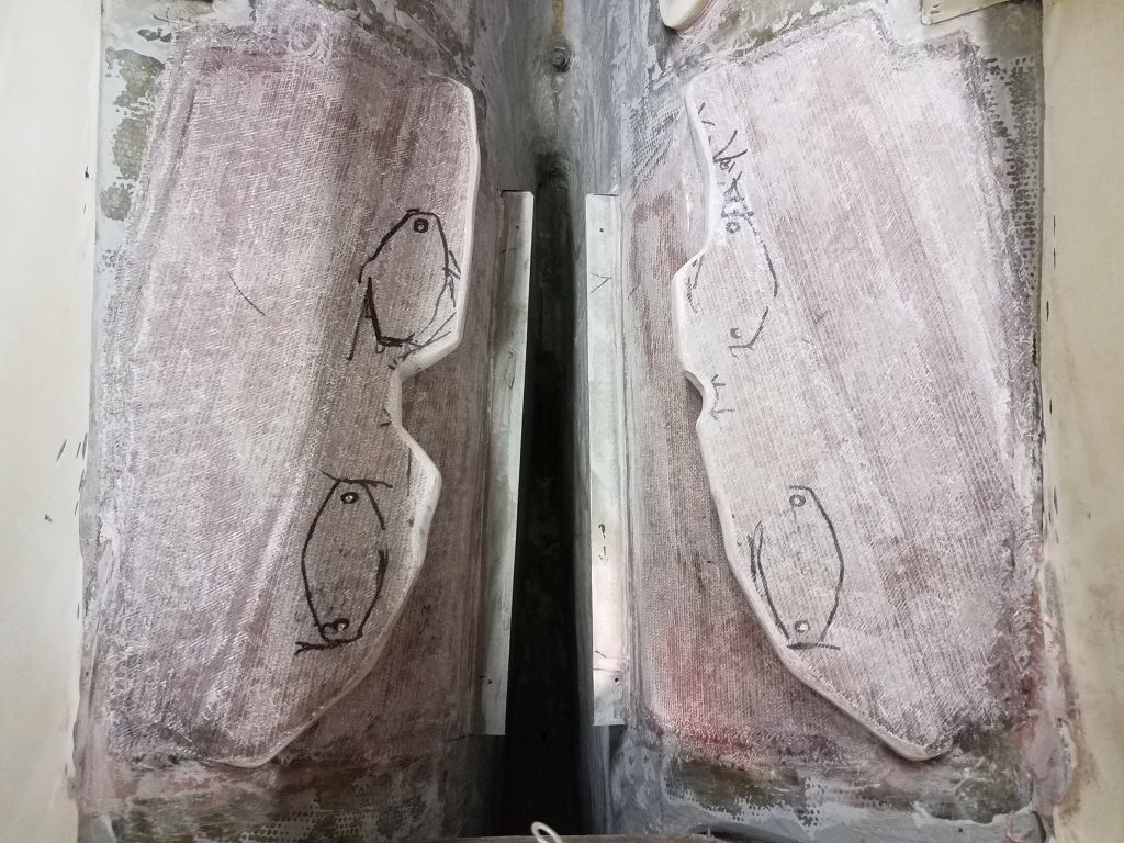
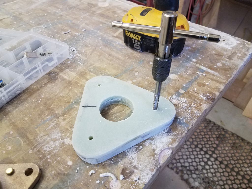
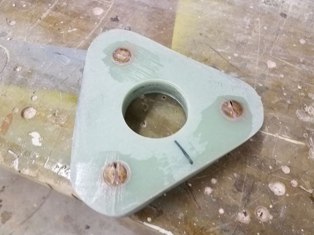
After cleaning up from the past couple days’ work in the engine room, I moved on with the through hull backing pad replacement. After cleaning up the new pad, I laid out, drilled, and tapped the fastener holes for the mounting bolts from the underside of the pad, just as I’d done originally.


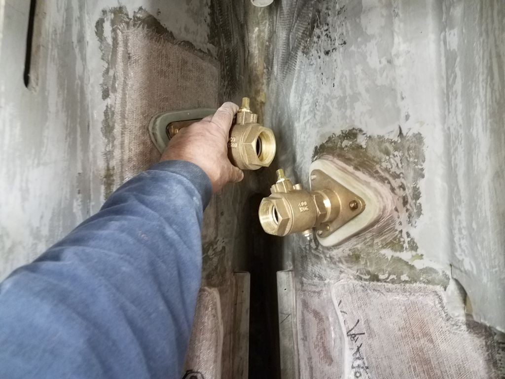
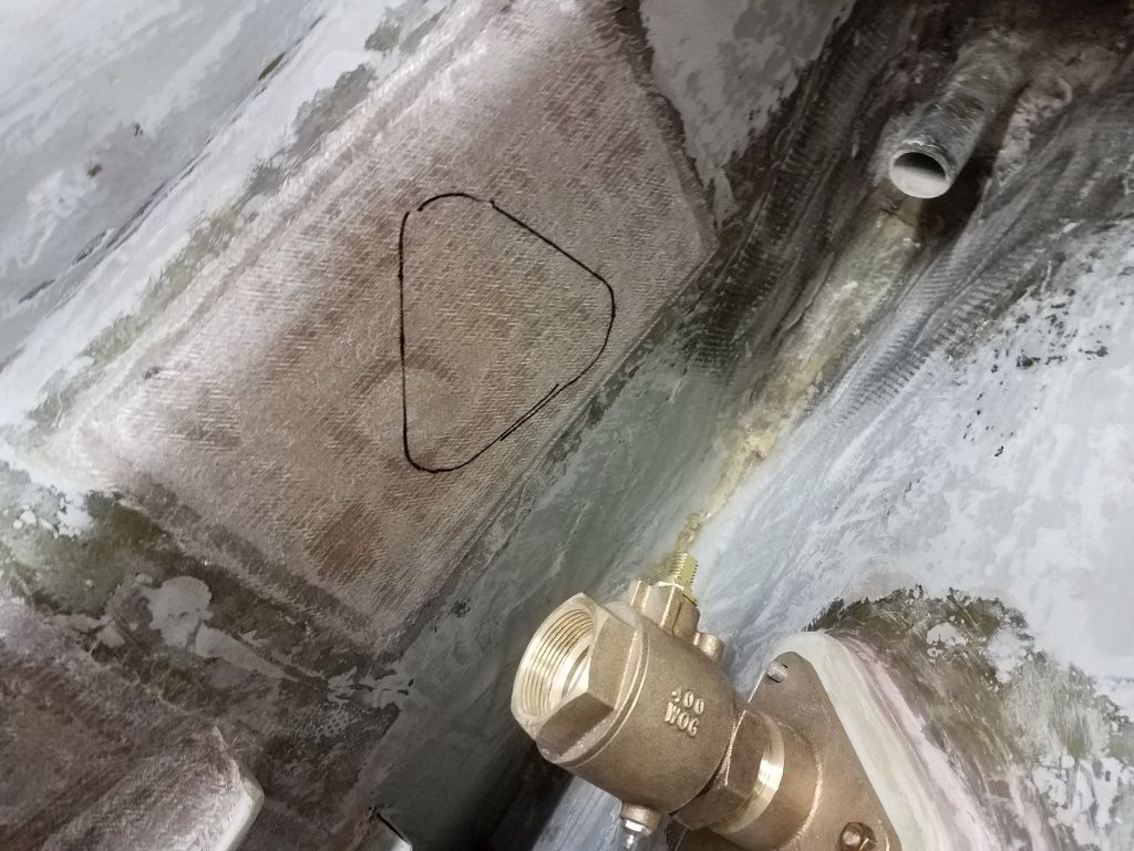
In the boat, I temporarily installed the port flange and valve, then, with the starboard side dry-assembled on the new pad, checked for clearance between the two valves and marked the hull accordingly for the new starboard pad. Meanwhile, I applied a layer of fairing compound over the outside of the patch. I’d wait to drill the new hole through the hull till the new pad was installed.
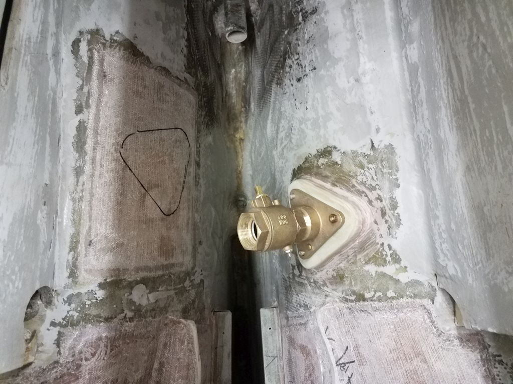
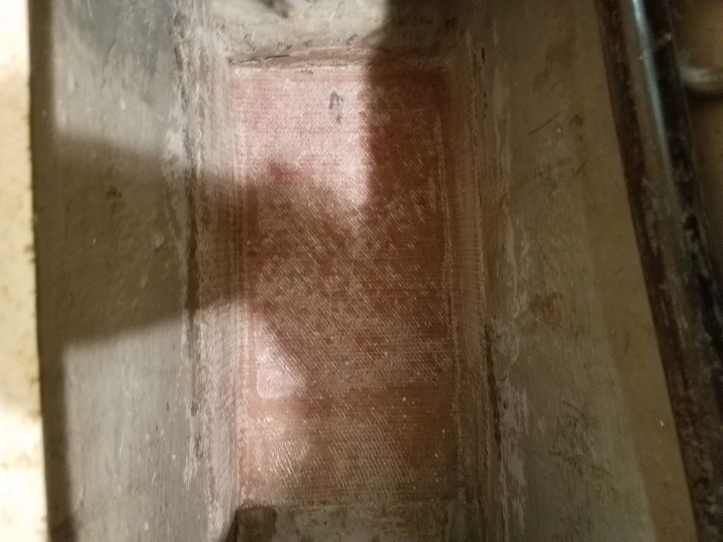
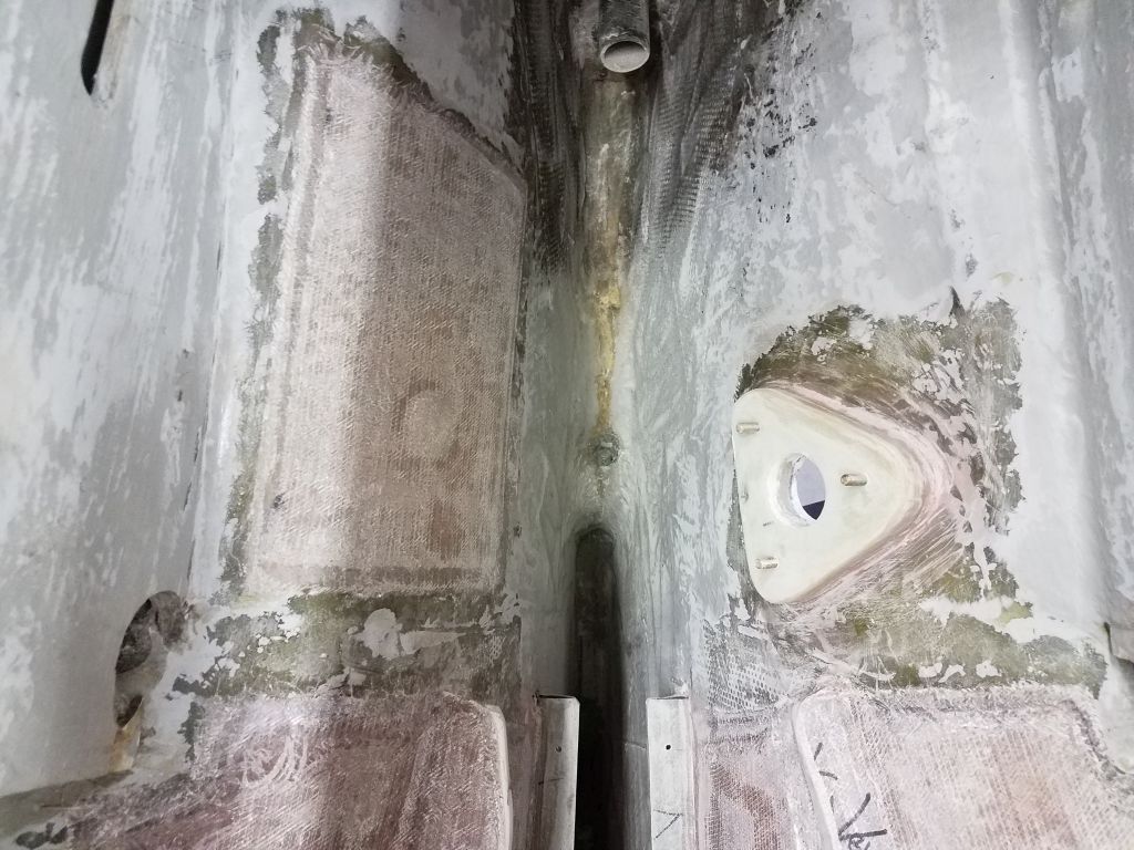
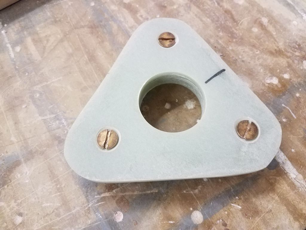
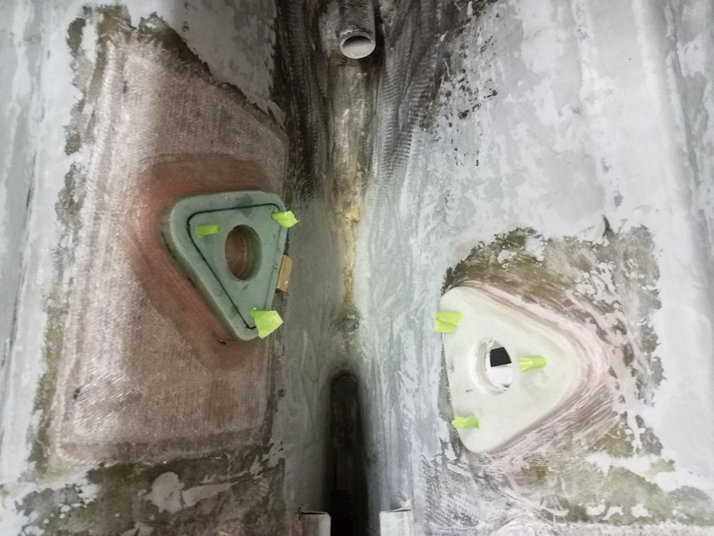
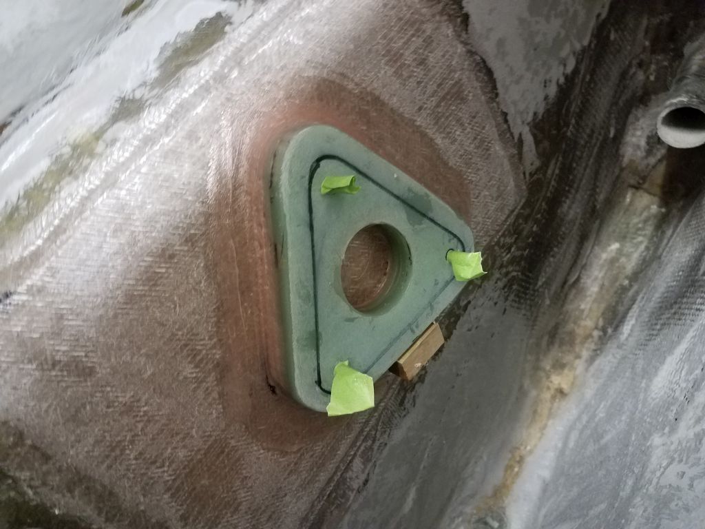
To install the new pad, I first loosened the three bronze bolts a bit, and added epoxy adhesive to the base of the threads to help hold them permanently in place. Up in the boat, I installed a support block with hot glue, which would help hold the pad in place on the near-vertical hull, then installed the G-10 pad in thickened epoxy. I left the new pad to cure overnight.

Total time billed on this job today: 5.25 hours (plus 1.25 hours not billed for the through hull rebuild)
0600 Weather Observation: 21°, cloudy. Forecast for the day: Slow clearing, windy, highs in the 20s