November 29, 2018
Dharma Rose 5
Thursday
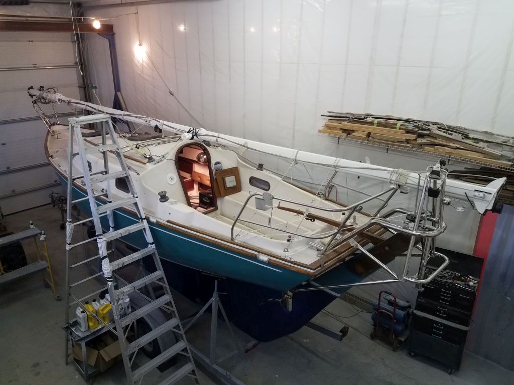
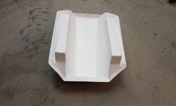
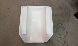
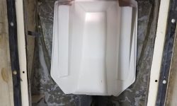
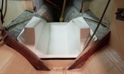
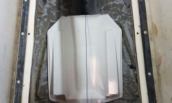
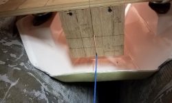
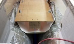
Before leaving the shop for a meeting in mid-morning, I spent an hour or so trying out the pre-fabricated engine foundation and drip pan that the owner had purchased from the original Contessa 26 builders in England. It was a nice-looking, clean fabrication that would streamline engine installation if it worked properly on this Canadian JJ Taylor version of the Contessa, which had some key differences in engine placement that I worried might make the pan a non-starter.
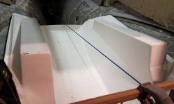
As it happened, the molded pan fit the hull well enough, but despite its clean fit to the hull shape itself, I could tell immediately that the pan was sitting far too high, and while modifying the pan was a possibility, the height difference at first glance appeared significant, given my knowledge of about where the engine needed to be, plus the way the shaft tube and foundation pan visually aligned (or not) in their respective locations.
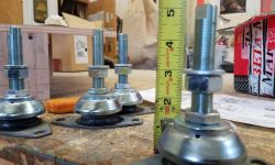
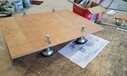
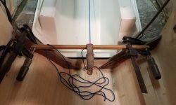
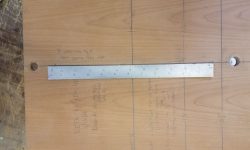
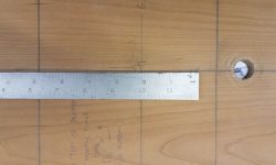
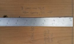
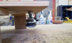
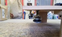
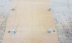
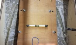
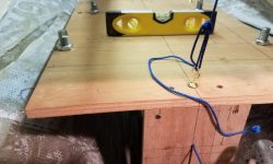
I retrieved from storage my plywood template for the Beta 14, which I built previously for another job a couple years before, and double-checked that the dimensions of the new engine hadn’t changed at all by reviewing the latest version of the Beta measured drawing, which still corresponded with the one I used to build the template in 2016. I set the flexible engine mounts to a mid-range 3″ height (as measured beneath the template base, which is representative of the base of the steel engine mounts themselves), as this would allow adjustment in either direction within the recommended adjustment limits of the mounting studs. I used a thick flat washer to simulate the height of the split locker washer that I’d use during the final engine installation so as to keep the adjustment height of the mounts as close to the real thing as possible. Then, I bolted the mounts to the template, using holes I’d bored for the 14-1/2″ mounting centers on this engine.
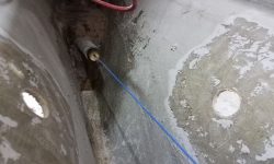
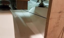
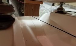
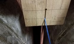
To start to get a rough sense of where things were, and a reality check for the engine pan, I set up an alignment string through the stern tube, holding it centered in the tube at each end with a wooden plug and securing the string tightly inside the boat after aligning it by eye through the center of the stern tube and plugs. The string represents, of course, the centerline and plane of the propeller shaft, the one critical reference point from which all engine placement follows. It was clear once more that the fiberglass pan was much too high, though the closeness of the string to the upturned aft end of the drip platform was the least of my concerns–though it did highlight just how misaligned the molding was in this boat.
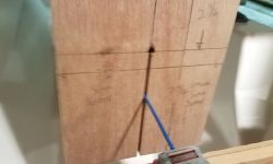
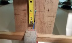
I set the engine template atop the engine foundation and checked its placement vis-a-vis the alignment string. At the forward end, as currently placed and adjusted, the string was 1-3/4″ below where it should have been (i.e. the engine was 1-3/4″ too high), while at the aft end it was even worse, as the string was nearly 3″ below its proper location (i.e. the engine was 3″ too high at the aft end). This was a pity, since otherwise the template fit so nicely on the prefab bed.
I could adjust the engine mounts down by 1/2″ or so, but of course that wouldn’t even begin to make up the large discrepancy. And while I’d not discounted it completely yet, I was skeptical that I’d be able to modify the existing pan enough to make up the large difference in height and basic placement.
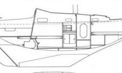
At issue, I believed, was a fundamental difference in the longitudinal placement of the engine in a Canadian boat versus the original English version. Though I’d never been aboard an English boat, various photos and other information, some of which went back to early project discussions with the owner in April, suggested that the engine in the English boats was substantially further forward, perhaps a foot further, which extended the engine room into the cabin beneath the companionway steps. Given the shape of the hull, if I could have slid the foundation a foot forward, it would have ended up also substantially lower, making for a good fit–as indeed it seems to be in the English boats.
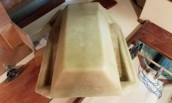
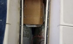
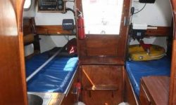
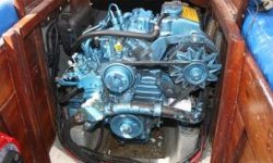
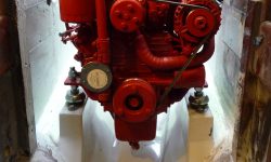
This series of images shows how the engine room is arranged in an English Contessa 26. In the Canadian version, the entire engine is well aft of the companionway bulkhead, and this key difference is why the molded pan ended up not being a feasible installation in this boat.
This photo, which the owner sent me some time back, shows the actual engine pan in an English Contessa, complete with Beta 14 atop. A nice fit…but this also clearly shows how far forward the engine is by comparison.
In arriving at these various conclusions, I also spent some time reviewing two other Canadian Contessa 26s that I repowered with Beta Marine engines, one, Equinox, in 2007, and the other, Salty, in 2016. Even these two ostensibly identical boats had key differences in their engine placements, and even with intensive review I still couldn’t put my finger on exactly what was different, other than Salty’s engine beds and engine were quite a bit higher for some reason; since the shafts both seemed to exit the deadwood in the same place in the aperture, the only thing that could be different and lead to a couple-inch difference in engine height might be the angle of the stern tube itself. In any event, these differences led to individual challenges in each case, and frankly this was all neither here nor there other than to help solidify my next notions.
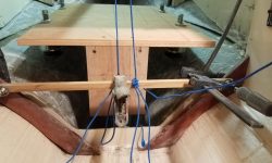
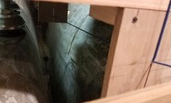
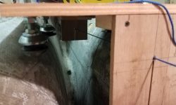
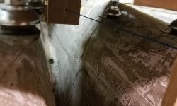
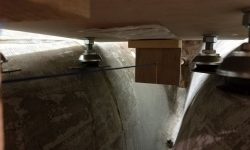
My next notions, as it were, were to check how the engine fit in the bare compartment, to identify or confirm my thoughts on how the after set of mounts would work in the space. So I removed the fiberglass pan, and set up the template in the engine room, holding it as necessary for the moment with some rough strings. My immediate goal was to determine how the after mounts would fit, or not fit, as the case would be, at their current 14-1/2″ width. I suspected based on the general appearance of things that they’d be too wide, and indeed the flex mounts contacted the hull much too high up, and didn’t allow the template to move down to where it needed to be with the shaft alignment string.
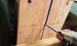
To deal with this (actually completely expected) issue, I removed the template and after set of flex mounts, then laid out, marked, and drilled new holes for the after mounts at 11-1/2″ centers, or the so-called Atomic 4 mount. Since the steel engine mounts were bolted on, and could be swapped at will, I planned to order a set of the narrow mounts for the aft end, which would reduce the width in the engine room to a workable point.
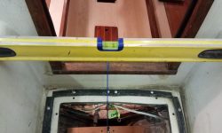
Before continuing, I double-checked the boat’s level from side to side, since now I was starting to approach more critical measurements and alignment procedures. Even though I’d adjusted the boat earlier, I wanted to be sure none of the machinations of engine removal and other work had shaken things out of alignment, but things still looked good, so I could proceed.
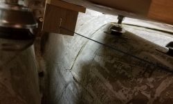
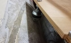
Once more I hung the engine template in the engine room with strings from above–a not-so-ideal means, but good enough for now, and simple and quick. With a few height adjustments, I eventually got the engine string through the two centers fore and aft as needed, and within a reasonable tolerance for the purpose at the moment. Even with the narrow aft mounting centers, there was just barely enough room there for the dangling flex mounts, given the indelible contours of the hull shape. I had room to move the engine a bit fore and aft as needed, and the way the support strings were it tended to pull the template aft a bit, so I felt like I had a workable (just) solution at hand. This is a small boat with a sensual, but confining, shape.
At this point I completely abandoned any pretense at considering the use of the prefab engine foundation, since if nothing else this exercise had shown that full-width mounting centers simply couldn’t work with this engine position, and perhaps this kept open the door for the owner to resell the molding to someone with an English boat. When considering modifying the template in the early stages, my concern was doing irreversible damage to the foundation that would render it completely useless to anyone, especially when I had grave doubts of any modifications’ effectiveness to begin with, so I was grateful to move on in a new direction and set aside the prefab–though I certainly would have liked it to work here, as it would have been a nice and convenient means of installing the foundations rather than starting from scratch.
I ordered materials from which I’d build the new foundations, and left things for the day.
Total time billed on this job today: 6.5 hours
0600 Weather Observation: 36°, cloudy. Forecast for the day: Mainly cloudy, windy, snow showers, around 40°


