February 12, 2016
Danusia 35
Friday
With a new Cutless bearing that I’d ordered after removing the shaft several days before still a no-show from my original vendor, I’d ordered another one from a second vendor, and it arrived on Thursday afternoon while I was working on a remote project. So with plans to reassemble the shaft, stuffing box, and coupling, I got back to work early in the morning so I could finish up the stern tube repair and prepare the Cutless bearing before my helper arrived to squeeze himself back into the bilge and put things back together.
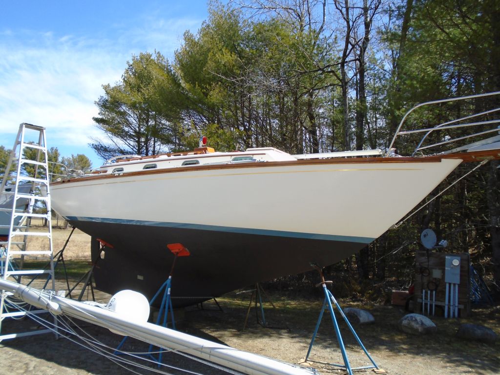
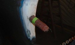
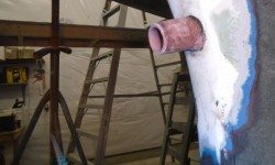
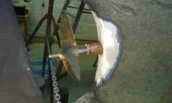
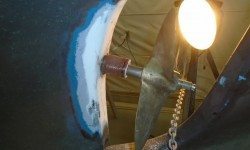
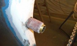
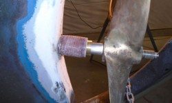
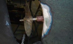
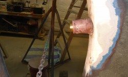
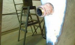
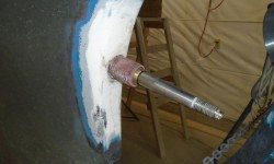
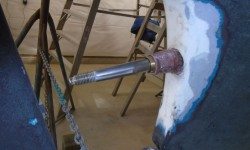
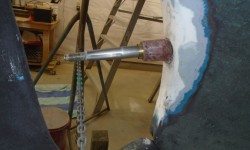
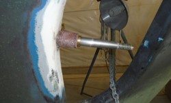
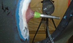
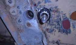
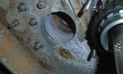
With some photos of the original setup as a general guideline for how much stern tube should be protruding from the deadwood, I mocked up the shaft through the tube now to make some reference marks and see how it all played out vis-a-vis the original photos and my own sense of things. Eventually, I determined that the stern tube had stuck out about 2″, and I masked off a reference line at this dimension so I could cut off the excess tube. After double-checking the dimension, I made the cut, and once more mocked up the shaft and propeller to ensure that there was ample room between the tube and the prop hub.
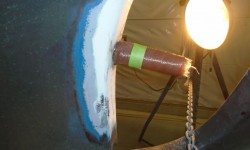
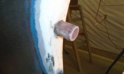
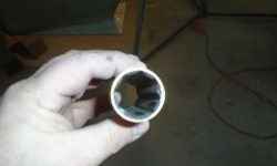
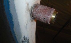
With the tube at the right length, I turned to the Cutless bearing. I had to lightly sand the inside of the tube to make the fit a little easier, but then the bearing slipped in with just the right amount of friction. The brass body of the bearing was necessarily slim, and the rubber lining minimal, in order to fit a 1″ shaft through a 1-1/4″ ID tube.
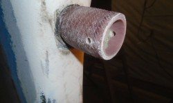
Pleased with the overall arrangement from the mockup, I prepared two threaded holes, at 9 o’clock and 3 o’clock on the stern tube and about 1/2″ in from the end, to accept set screws that would hold the bearing in place. Before installing the set screws, I used a small drill bit to just barely dimple the brass bearing housing at each location to better accept the set screw point. Then, I installed the bearing, using a tiny amount of sealant on the body to help secure it and leaving about 3/8″ of the bearing standing proud of the end of the stern tube.
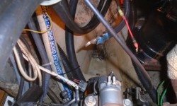
Normally I might have liked to have faired in the tube with the aperture before proceeding with the shaft, but with a desire to wrap up the stuffing box project and with schedule constraints, I could take care of that later. I finished up the preparations just in time for my helper Jason’s arrival, and we got right back to the reassembly, starting with cleaning up the bilge area aft of the engine while access was as good as it would ever be.
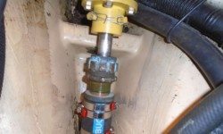
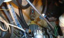
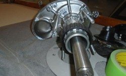
The packing box hose was an extremely tight fit over the stern tube, but Jason eventually got it on and secured. Then the space between stuffing box and transmission coupling was so minimal as to leave barely enough room to actually fit in the shaft coupling and brass key, a process made more difficult by the fact that most of the work had to occur one-handed. But though challenging, of course it was possible to reassemble, and without too much fighting Jason got things put back together and secured the coupling set screws into their shaft dimples, and moused the bolts to prevent movement. From there, it was a relatively simple matter to bolt the coupling back in place to the transmission coupling with new bolts.
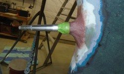
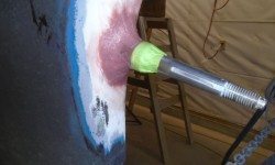
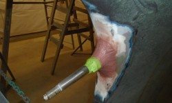
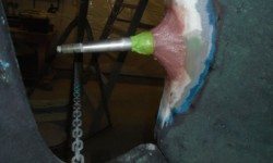
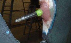
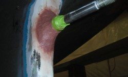
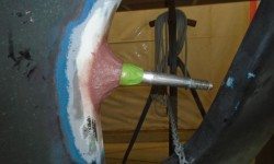
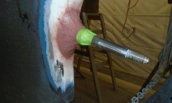
With that done, I could start fairing the stern tube in to the aperture, much the way it had been when we started. To save some future person some of the agonies we experienced during removal, I chose to leave the bearing set screws exposed, rather than burying them beneath the fairing as they’d originally been. So I masked off the very end of the stern tube, and over the exposed end of the bearing and shaft, then mixed up a preliminary batch of epoxy thickened substantially with structural and adhesive fillers, smoothing it into place around the stern tube and approaching the final shape, though to avoid excess exotherm I’d do the buildup in 2 or 3 total applications. I figured the first application would cure past the “hot” stage before the end of the day and would allow another application later, so for now I moved on to the next thing on the list.
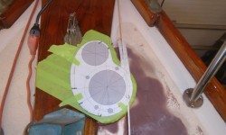
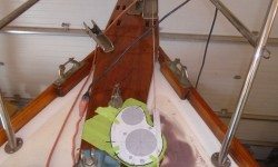
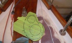
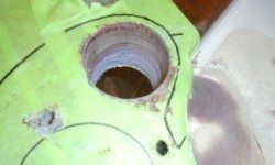
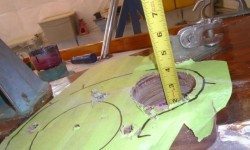
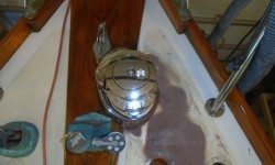
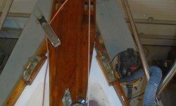
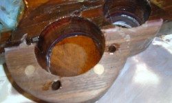
It was time to drill the large holes required for the windlass installation, which would allow me to dry-fit the windlass and make sure everything was looking good. So on the foredeck, I carefully set up the base template once more, ensuring its proper alignment with my teak base and, more importantly, with the anchor roller on the platform. Satisfied, eventually, with the layout, I used a center punch to mark the centers of all the holes I had to prepare, including a 3-1/8″ hole for the chain pipe; a 4″ hole for the windlass shaft and body; and four 3/8″ holes for the fixing bolts.
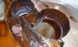
Starting with the chain pipe hole, I used a hole saw to create the opening. This was a long process, as this particular bit was very dull, as it happened. With frequent stops to clear the teeth on the saw, and occasionally chiseling out the waste from within the hole to allow the hole saw to penetrate the growing depth, I eventually made my way through the roughly 2″ of solid teak, then a 3/8″ (more or less) thickness of solid fiberglass deck (the fiberglass was much easier to cut than the teak), then a thick layer of filler/putty/adhesive, and finally the aluminum cross member inside the chain locker. With the nearly 4″ deep hole complete, I retired the exhausted hole saw permanently with honors.
The next hole, for the windlass shaft and body, was even larger, but as it turned out it was much easier to drill. After giving my heavy-duty drill some time to cool off from its own heroic efforts on the first hole, I chucked in the 4″ hole saw for the final hole. This saw was much sharper, and cut the teak with greater ease, and this large hole also ended up completely aft of the putty/aluminum structure I’d dealt with on the forward hole, so with hardly any ado at all, I was through. Drilling the four small holes for the fixing bolts was a cinch.
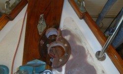
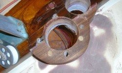
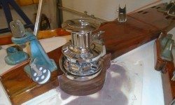
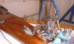
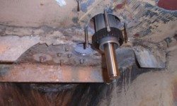
The windlass fit into place quite nicely, and with it finally through the deck I could look from beneath and start to figure out the details of a backing plate that I felt was required for added strength. Fortunately, I’d not need to worry much about building up the backing plate to match the thickness of the aluminum sub structure, as the bolting area of the windlass was aft of this point, other than one bolt that was close to the edge and would require something thicker there.
Meanwhile, on the deck side I was pleased to find that the lead from the anchor roller to the chain wildcat was even better in reality than I’d hoped for while laying out the templates.
I’d move forward with the final windlass installation details in the immediate future, but for now my next task was to seal the insides of the large holes (and, as much as I could, the smaller bolt holes) with epoxy to help protect the wood within. Fortunately, there was no core material to deal with in any of these holes.
The windlass base itself had no flat surfaces to speak of, and wouldn’t be easy to seal well. It came with a gasket, which hardly seemed sufficient on its own, so I’d find a way to add some better sealing material at the most critical parts of the windlass’s deck penetration.
To round out the day, I applied a second coat of filler to the stern tube, as the original coat had cured sufficiently over the past four hours.
Total time billed on this job today: 7 hours (Tim); 1.5 hours (Helper)
0600 Weather Report:
-10°, clear. Forecast for the day: sun, high 16°


