

February 8, 2016
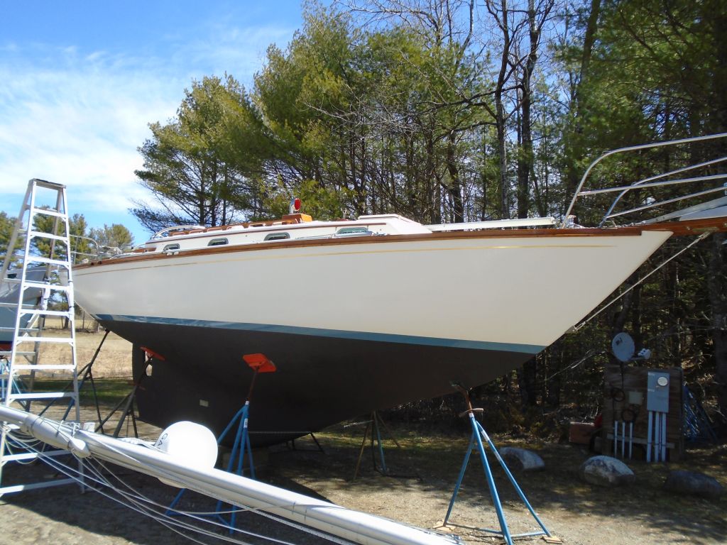
Danusia 31
Monday
Having ignored the steering pedestal at the end of last week, I took several minutes first thing to clean and sand the last application of fairing filler on the base. The pedestal was now ready for primer, but for the moment I had bigger fish to fry, so I’d get back to the pedestal in due course.

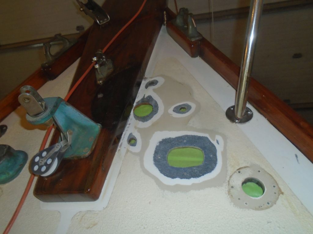
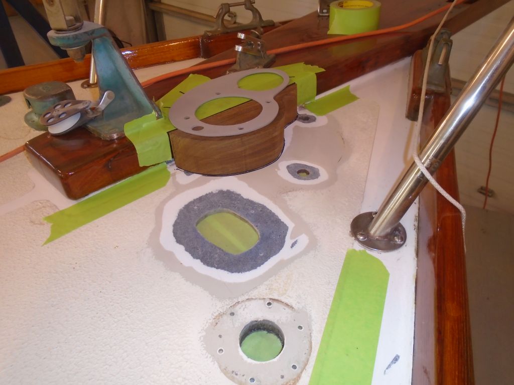
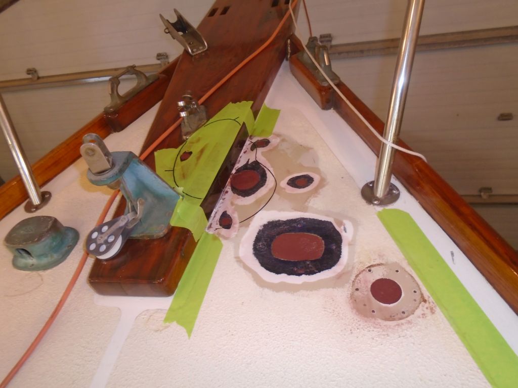
I set up for and spent some time sanding the foredeck, both above and belowdecks, to prepare the various obsolete holes in the deck for filling and patching so I could continue the physical windlass installation. This included the old windlass shaft hole and bolt holes, the old manual chain pipe, and the old foot switch opening. After cleaning up, I masked off the holes from beneath.
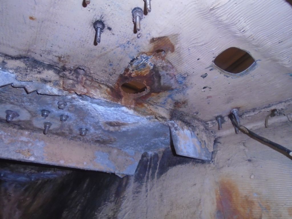

I trimmed the teak windlass pad a little smaller, which I thought looked much better, and spent a few moments working on its basic placement once more, as yet another confirmation of the location and to ensure that the way was clear in all ways, above and belowdecks. The chain pipe was close to the staysail stay location, but with the large full-width glassed-in aluminum backing plate beneath I didn’t think there would be an issue with support. This area of the aluminum (as seen in one of the photos above) was already partially cut away and corroded from the old windlass installation, and happily the new chain pipe would pass right through this area.
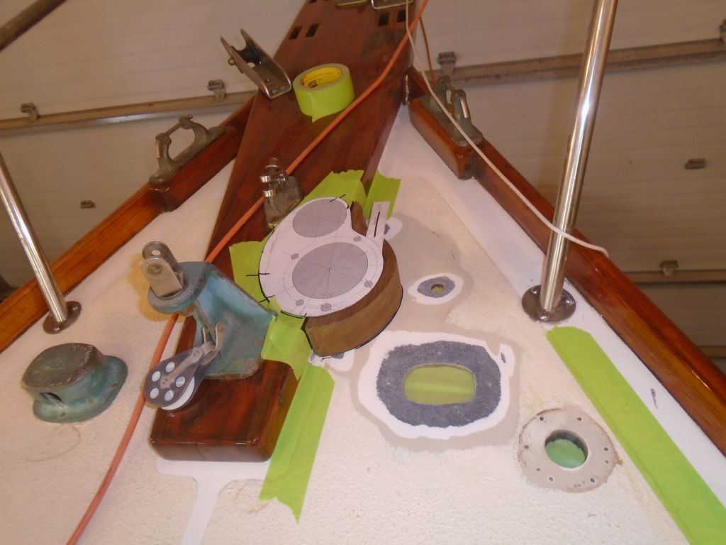


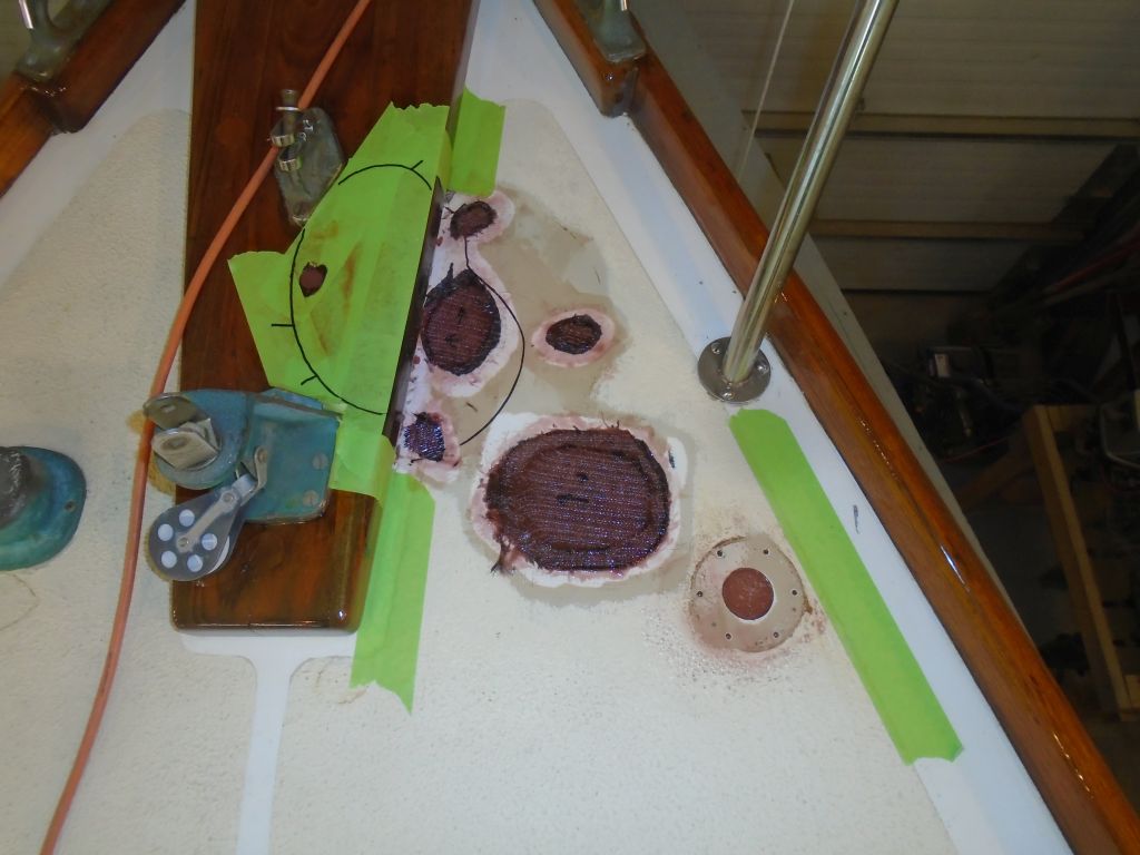
Next, I filled the various holes with a thickened epoxy mixture. Later in the day, when the fill had cured somewhat, I applied fiberglass patches to the top sides of the openings where needed. I didn’t fiberglass the switch location since I planned to locate one of the new switches in the same place, but since it required a different sized (and much larger) hole I’d filled the original so I could redrill as needed.
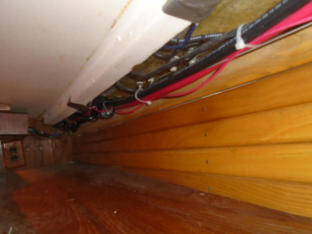
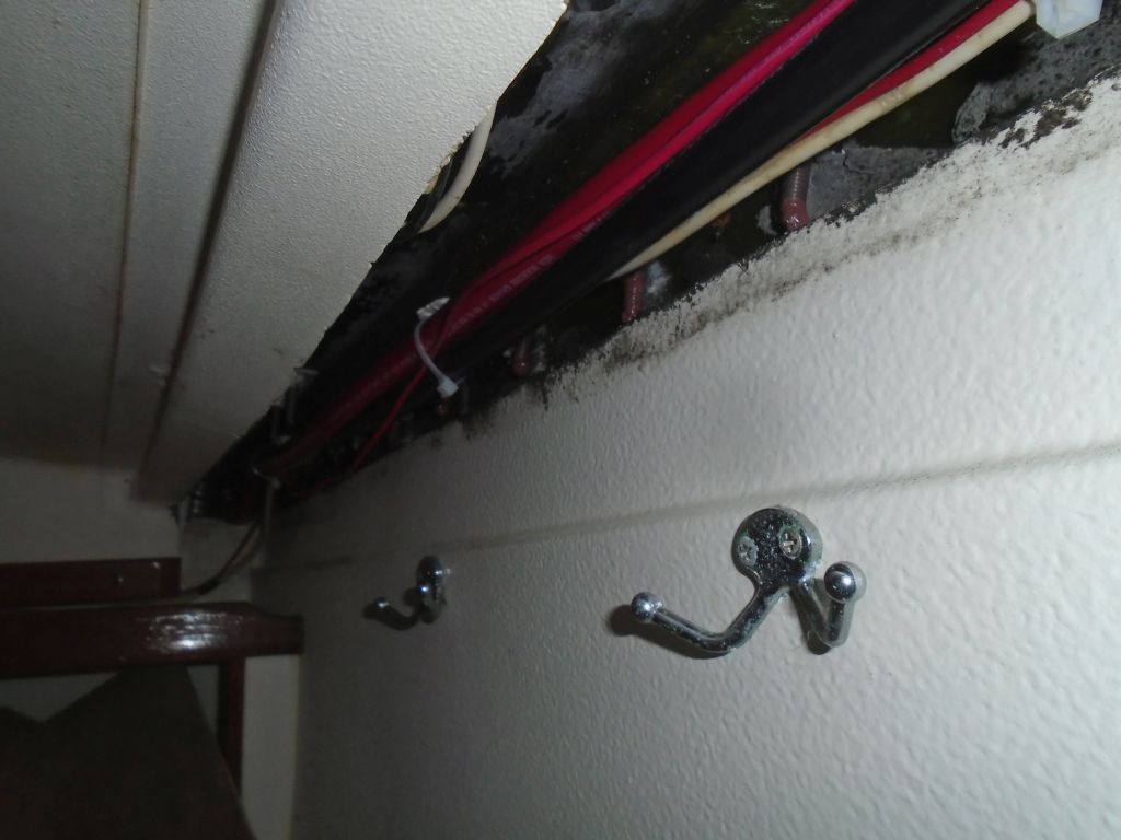
Preparing for the new windlass wiring, I installed wire tie mounts along the underside of the deck in the port wiring channel.
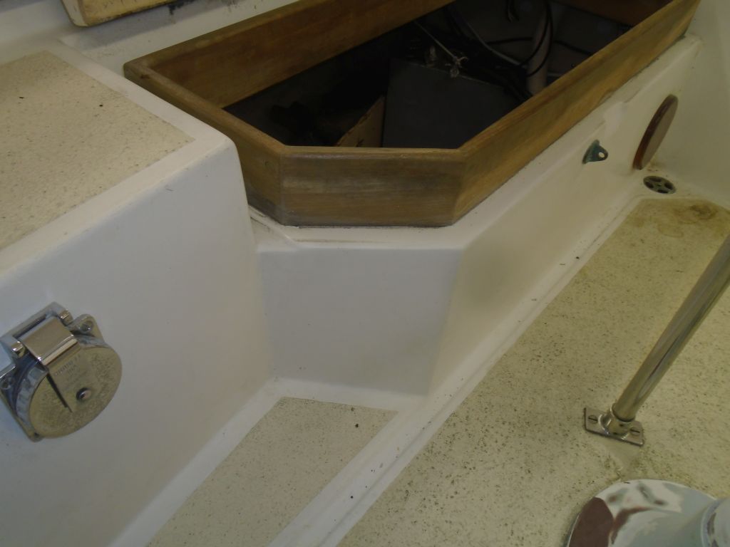
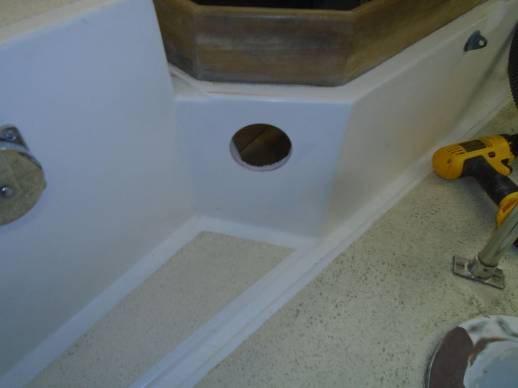
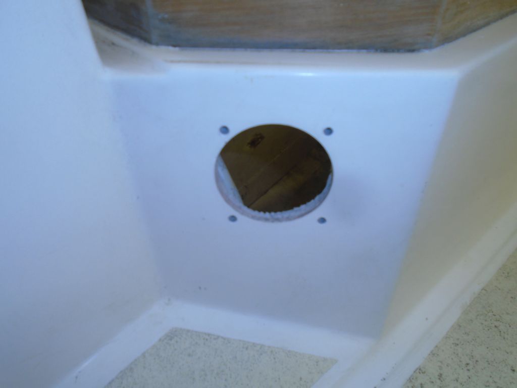
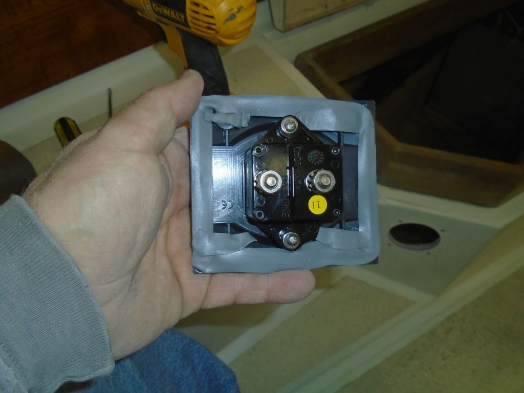
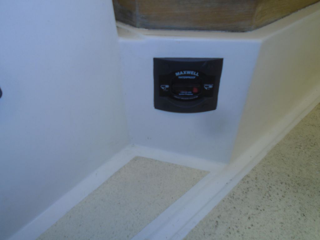
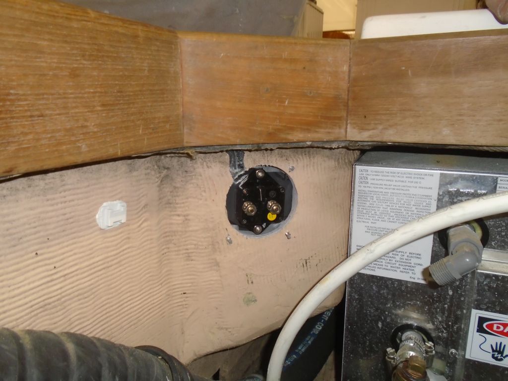
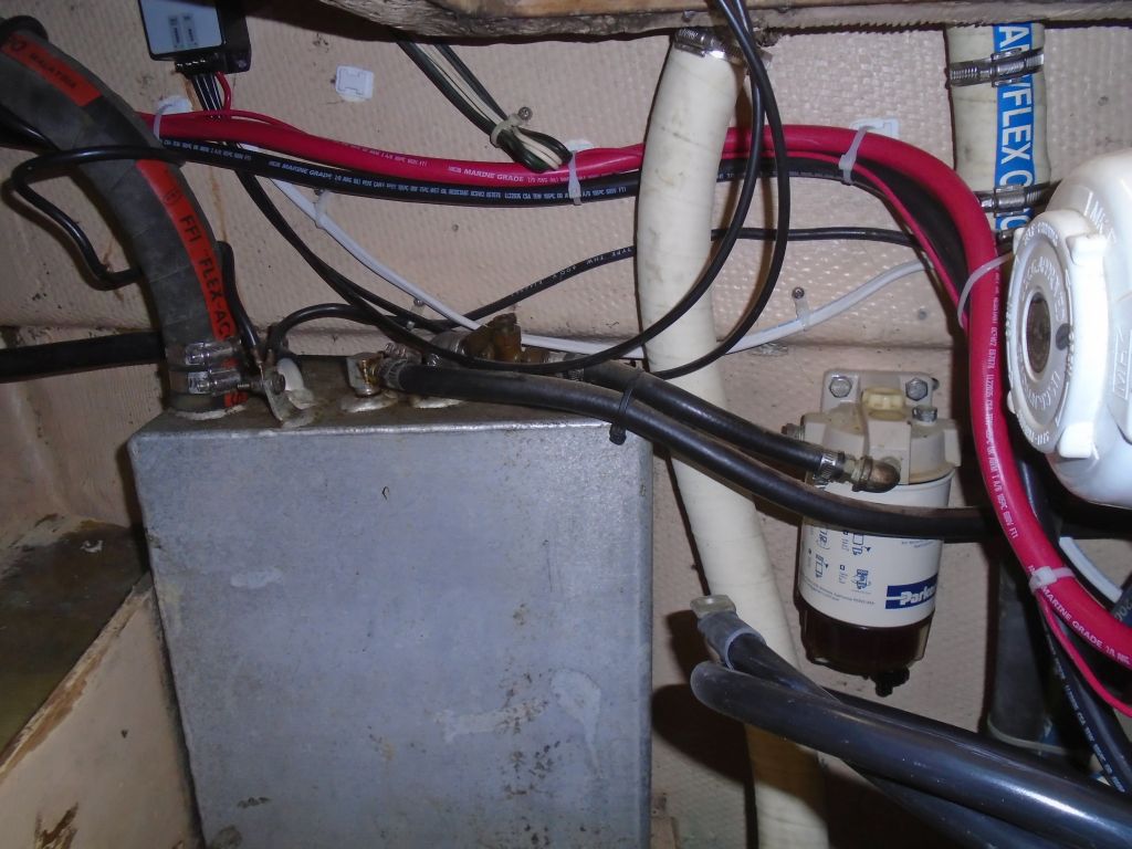
The windlass required a main breaker, and we chose to locate this in the cockpit. I found a good spot near the helm on the port side, which was convenient to both the main power source (battery) and the route forward for the wires. I installed the breaker in the huge hole required for it. (What is it with equipment manufacturers’ obsessions with massive holes for their installations?)
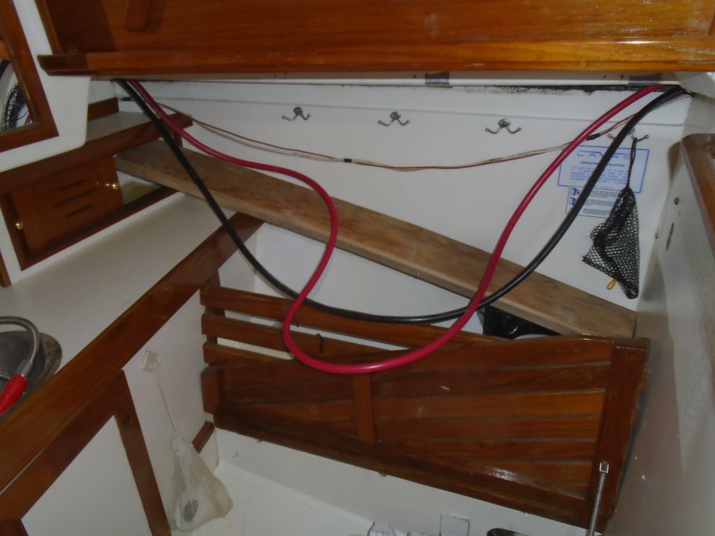
Now I led in new cables for the windlass, size 2/0. This is what had been in place for the old windlass, but I realized belatedly that they were somewhat larger than what was actually required by the new unit. Better to have too much cable size than not enough, but the heavy cable was no fun to work with. I spent some time interpreting the various wiring diagrams for the windlass and its accessories, working up my own rough drawing for the wires required for this specific installation, including two foot switches and a remote control unit.
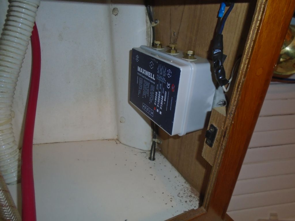
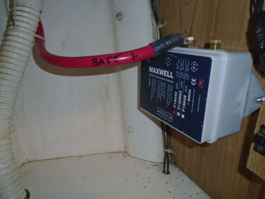
Space considerations and manufacturer admonishments dictated that the windlass control box (aka solenoid) be mounted safely away from the chainlocker, and there happened to be a relatively convenient space in a locker at the aft end of the port v-berth. The control box was very large but easy to mount with a pair of bolts, retaining decent if not ideal access to the cable terminals on top and smaller wiring terminals on the bottom.
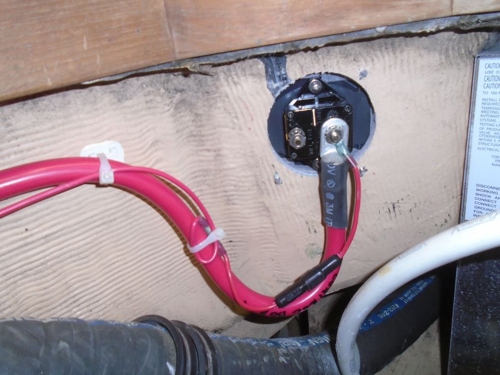
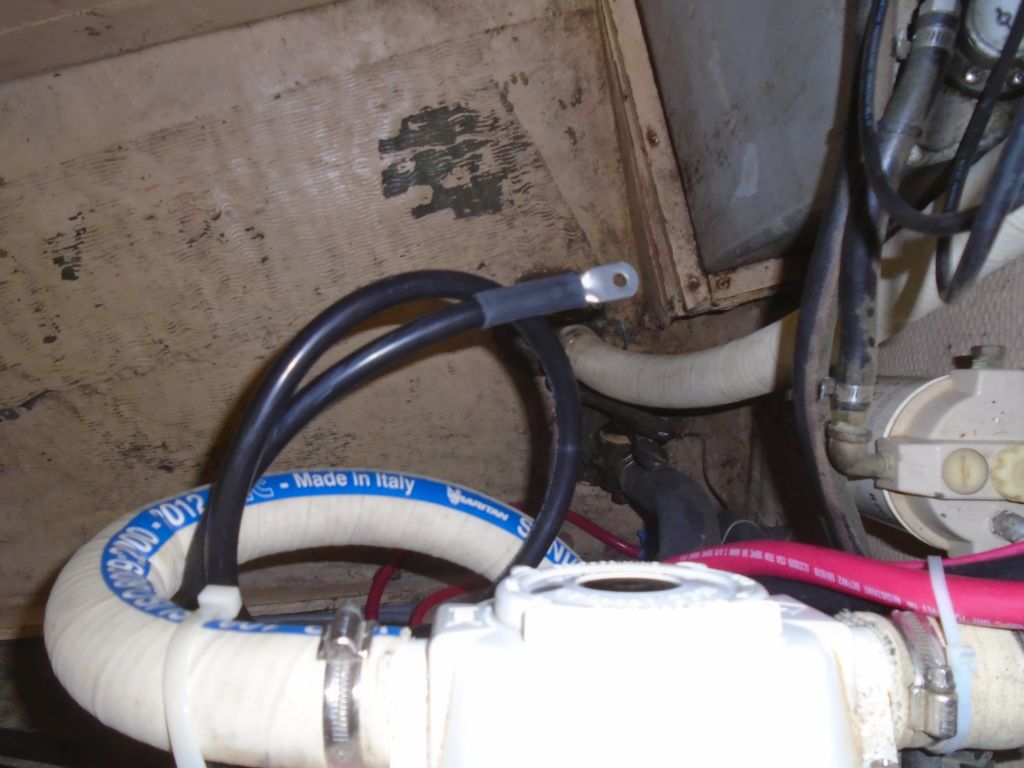
There’d be a pair of the heavy cables running from the control box to the windlass itself, and one positive cable from the cockpit (breaker switch/battery) to the control box. In addition, one negative cable had to run from the battery compartment directly to the windlass motor for grounding. So with the two longest runs led in, I made up the first two terminal ends as needed, for the control box and (eventually) the negative cable for the windlass motor. I also led in a smaller wire required by the wiring diagram. These were all the longest wires in the installation.

This allowed me to pull back and tie up the excess wire along the wiring route aft and into the cockpit locker so I could make up the ends there as needed. The exact termination point of the negative cable would probably be a battery terminal, as I didn’t see a negative distribution buss, but with the batteries removed and not a lot of excess cable I simply made up the terminal at the very end of the 35′ of cable length that I’d provided, which would allow it to reach to the battery compartment easily. For the positive wire, I ran it aft to the new breaker switch, where I installed it (and the smaller wire mentioned above) to the proper terminal, along with a terminal cover. I’d continue the wiring next time.

Total time billed on this job today: 7.75 hours
0600 Weather Report:
10°, mostly clear. Forecast for the day: clouds increasing, breezy, snow late in the afternoon and evening.