

January 15, 2021
Lively Heels Phase 3-5
Friday
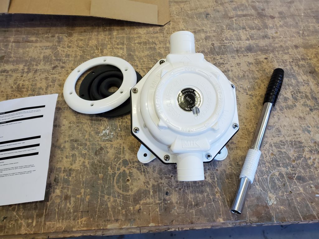
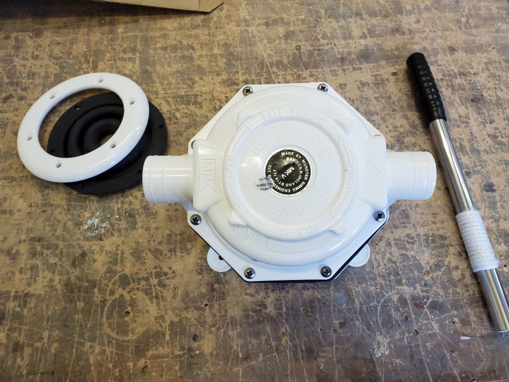
With the old sewage system out of the way, it was time to turn to the replacement system. The owner requested a simple system that would send all waste to a new holding tank, and from there the tank could be either manually pumped overboard in appropriate waters, or discharged to a shoreside facility when needed. In the time since I finished removing the old system, I’d ordered the new tank, though it had not yet arrived, as well as other components of the new system, including the manual waste pump: Another Henderson/Whale Mk IV like the toilet pump itself.
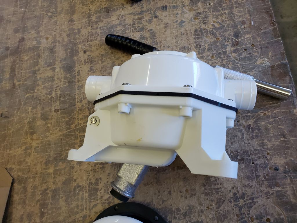
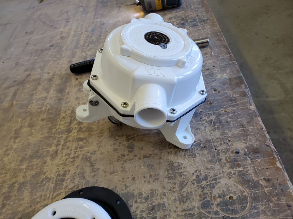
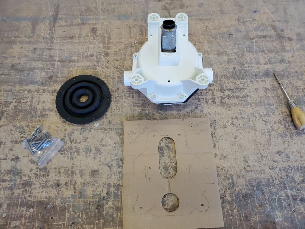
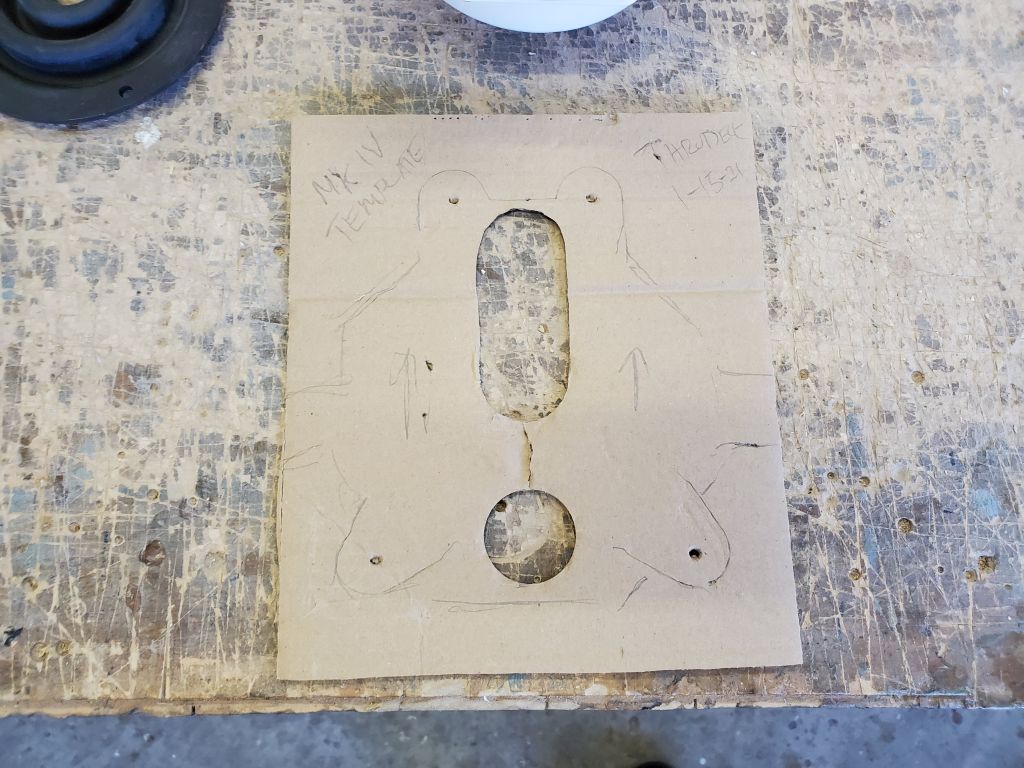
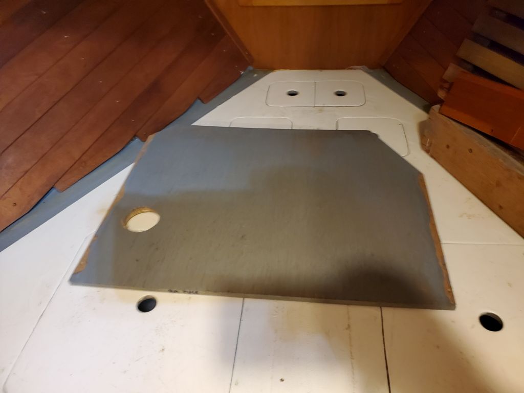
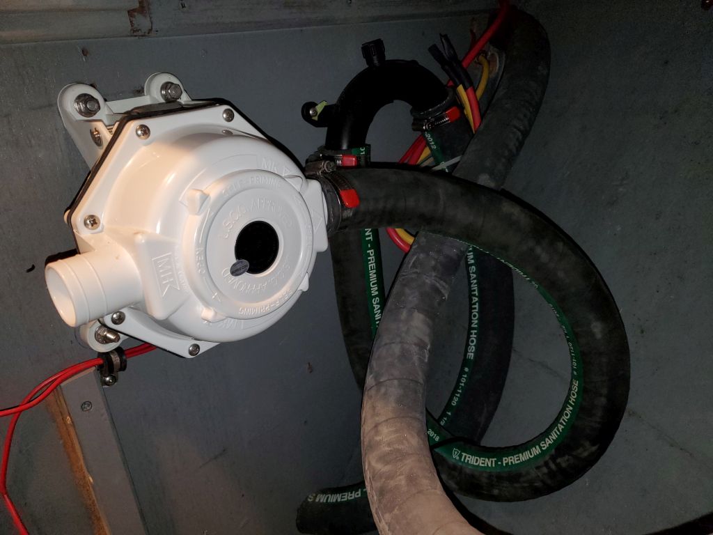
Now I prepared to install the new waste pump. The instructions for the through-deck (or through-bulkhead) talked of a mounting template, and it seemed I might have used a template for the original head pump I installed in 2014, but I could find no such template available, so I made my own template to show the cutout required for the pump handle and four mounting bolts for the pump itself. I also rotated the pump’s cowl to change the flow direction from the standard vertical orientation to a horizontal orientation that would better match the installation specifics at hand.
In the compartment beneath the forward berth, I removed a side panel to gain better access to the existing sewage hoses.
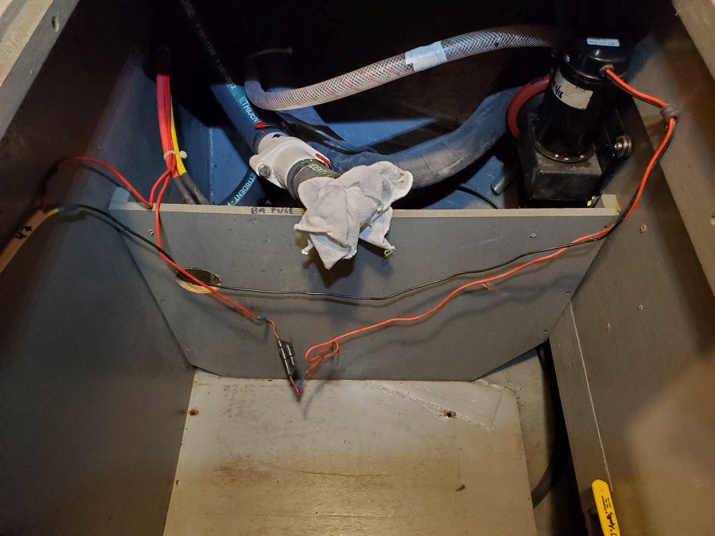
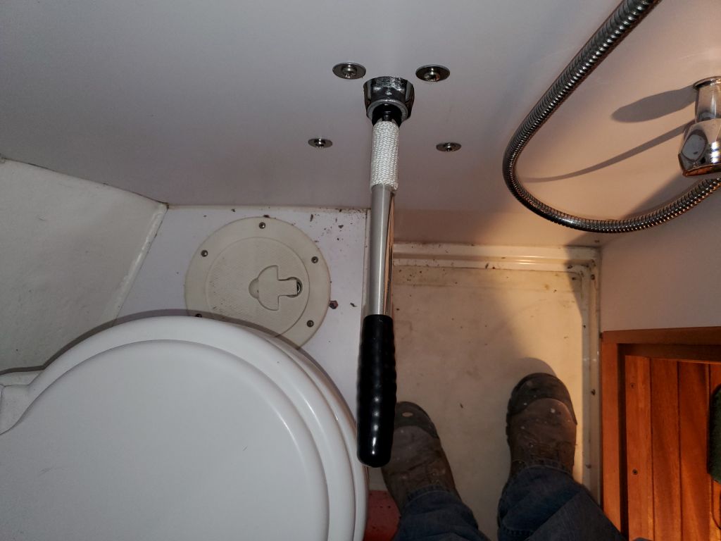
There were severe space constraints for the new pump, between the height of the berth platform, the nearby faucet controls, and the head platform and toilet itself (for pump handle clearance). Ultimately, these various obstructions, along with the bulk of the pump itself, more or less dictated only a single possible location for the pump, which fortunately happened already to be a clear space within the forward compartment.
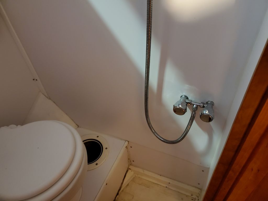
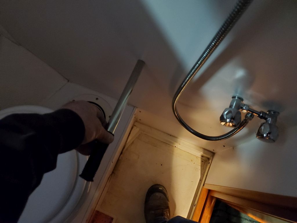
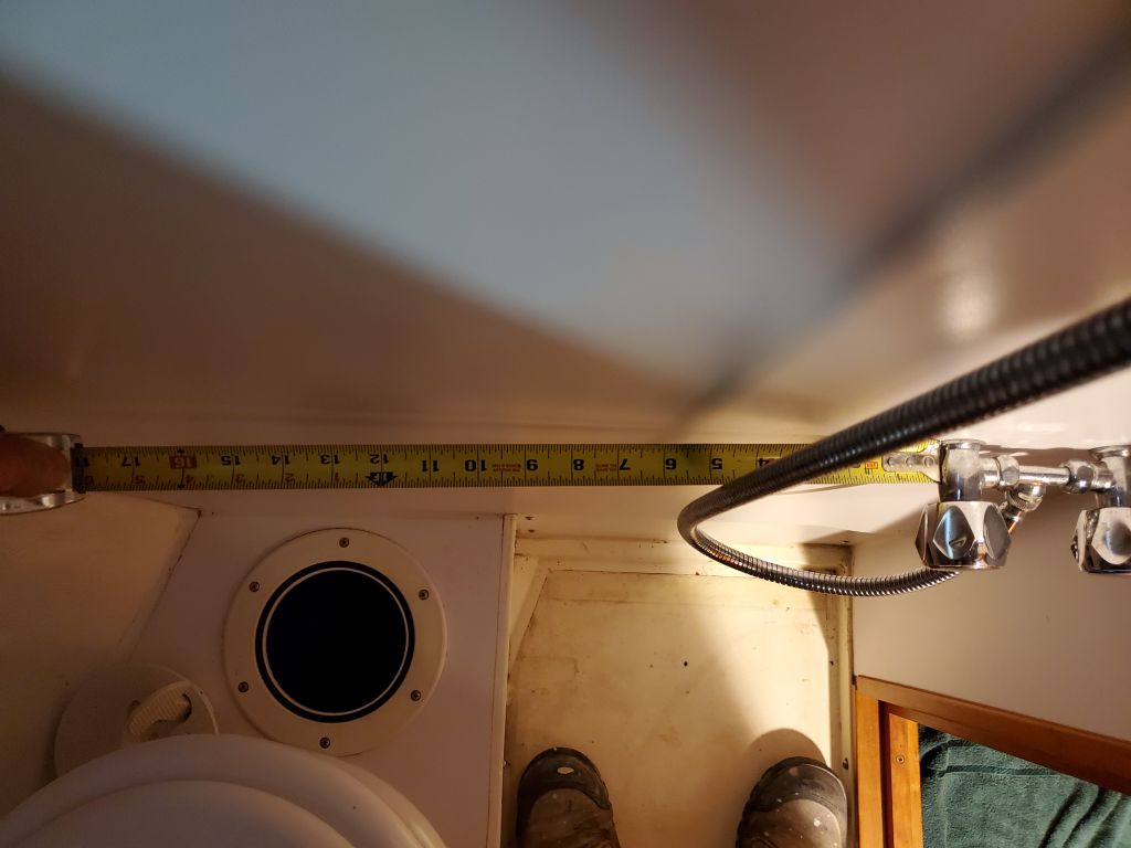
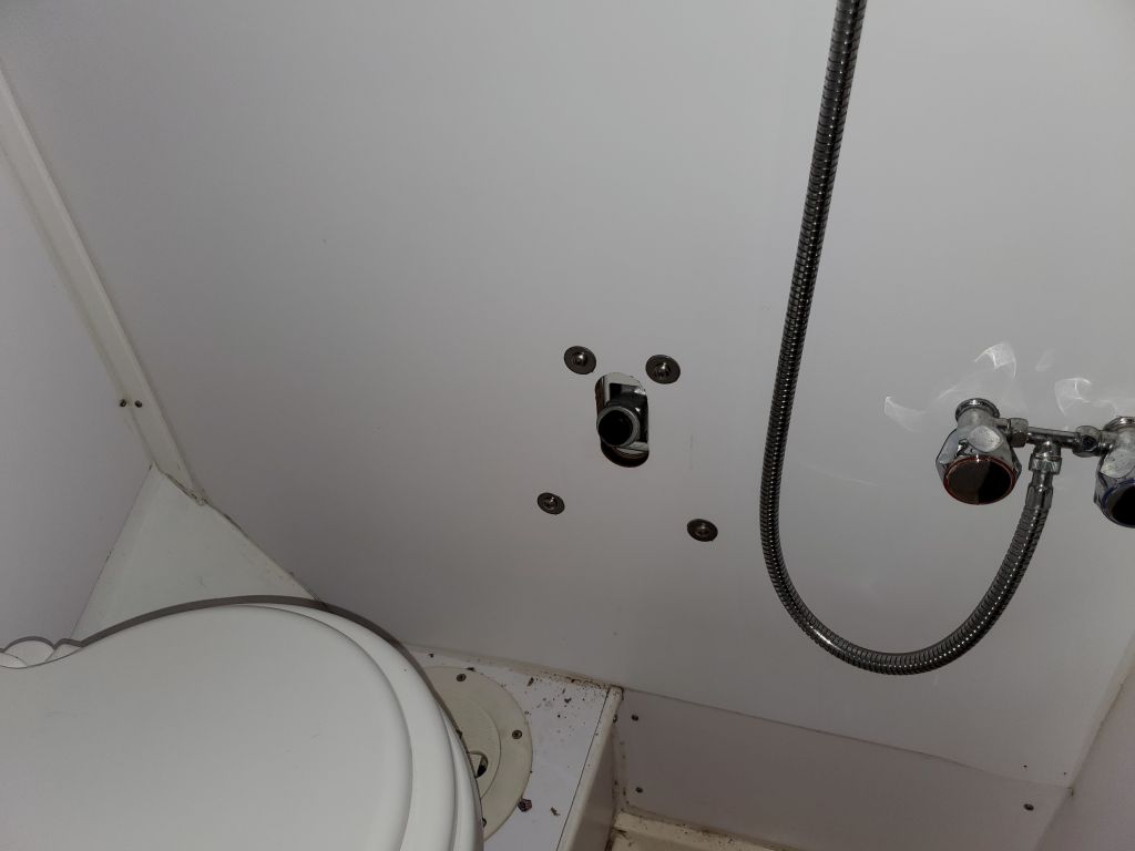
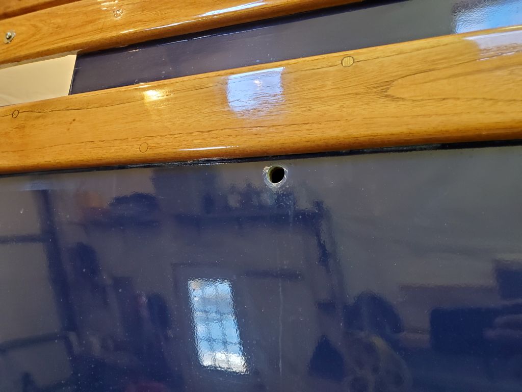
With the basic location determined, I used my homemade template to mark the mounting holes and pumping slot on the forward side of the bulkhead. I drilled a pilot hole through the rough center of the slot to double-check that there would be handle clearance in the head compartment; even in the best location the clearance was tight, but it was sufficient to allow full throw of the handle in both directions, without interference with the toilet. From there, I could cut the slot for the pump handle.

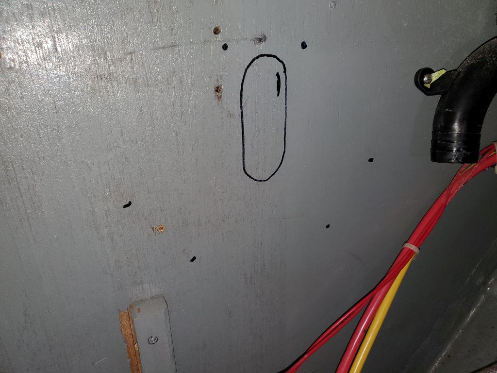

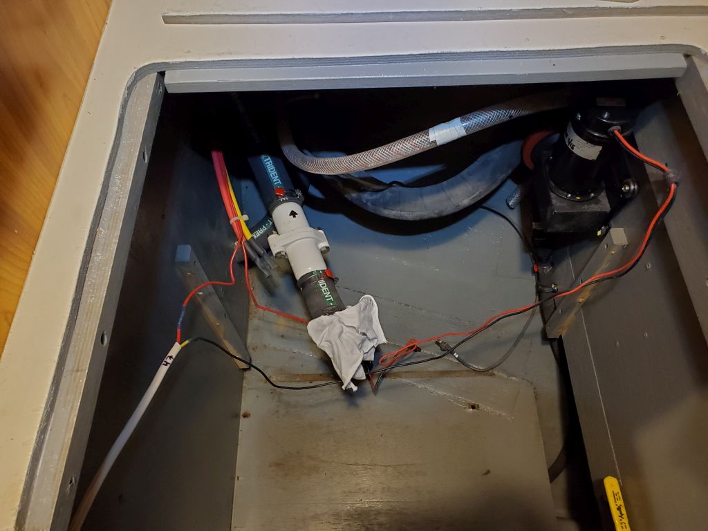
As essentially straightforward as this installation was in theory, in practice it required a lot of back and forth between the forward cabin and the head, a process complicated by needing to continually clamber in and out of the tight (and high) opening to the forward cabin, and into the adequate but still tight space where the old holding tank system had been, and so forth. I had to do this multiple times as I laid out and drilled the four mounting holes for the pump, as well as securing each of the bolts in turn, since I couldn’t access both sides of the bulkhead at the same time. I sealed each bolt penetration with a large washer and butyl sealant, and eventually the pump housing was in place.
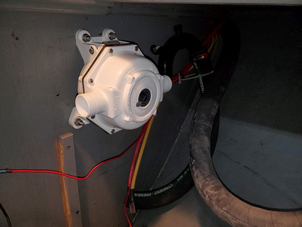
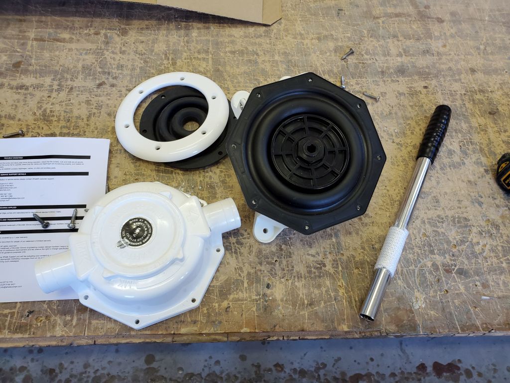
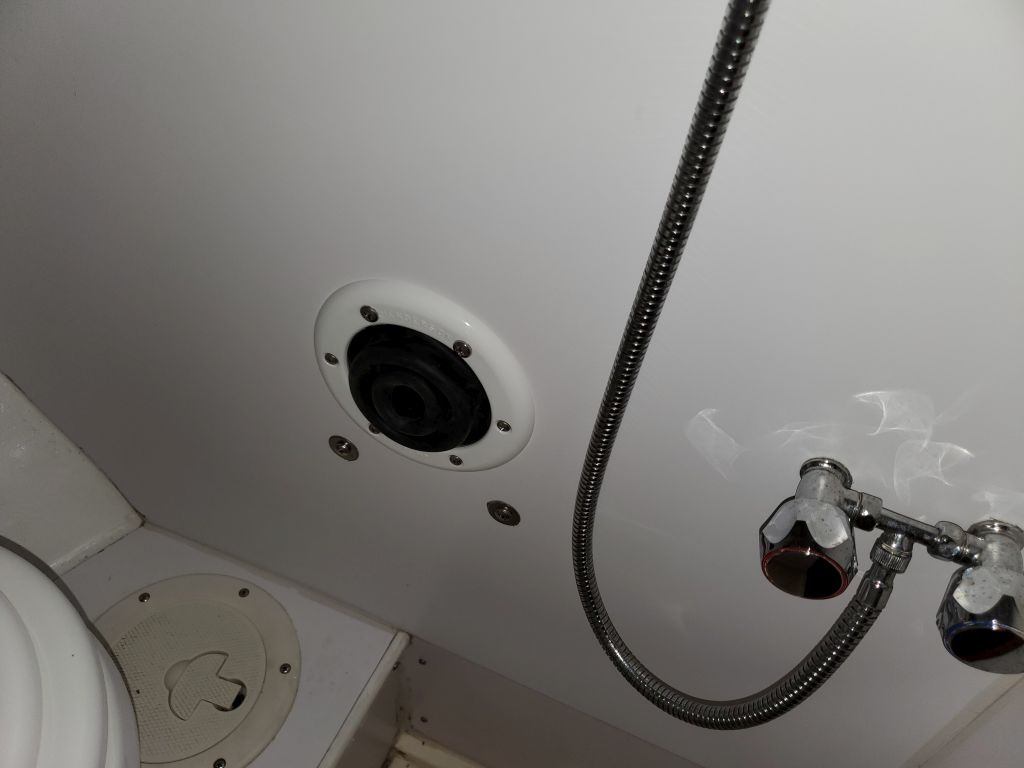
Now I could finish the installation with the rubber bellows and cover plate from the head side. I’d forgotten from my last such installation nearly seven years earlier that the top two holes in the bellows mounting ring corresponded with the top pair of bolts securing the pump, so I had to remove these two bolts and reinstall them through the plastic ring–no trouble, just more back and forth and repeating the processes I’d done earlier. In addition to the rubber bellows, which flange extended behind the entire mounting ring, I added more butyl tape sealant behind the ring to seal all the fixing screws.

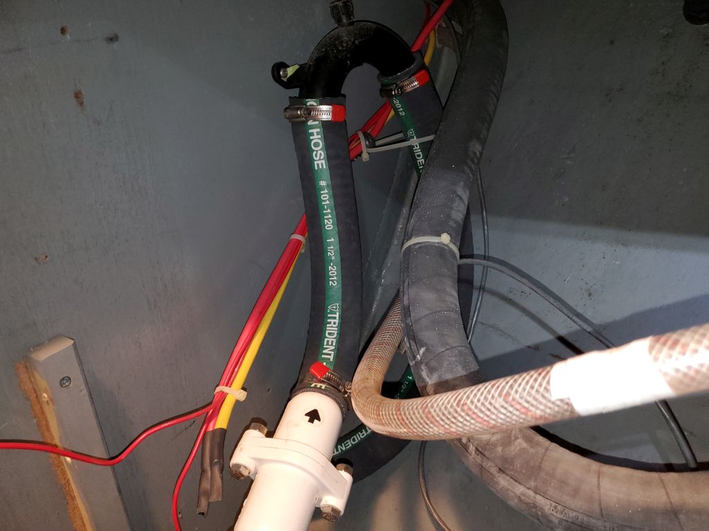
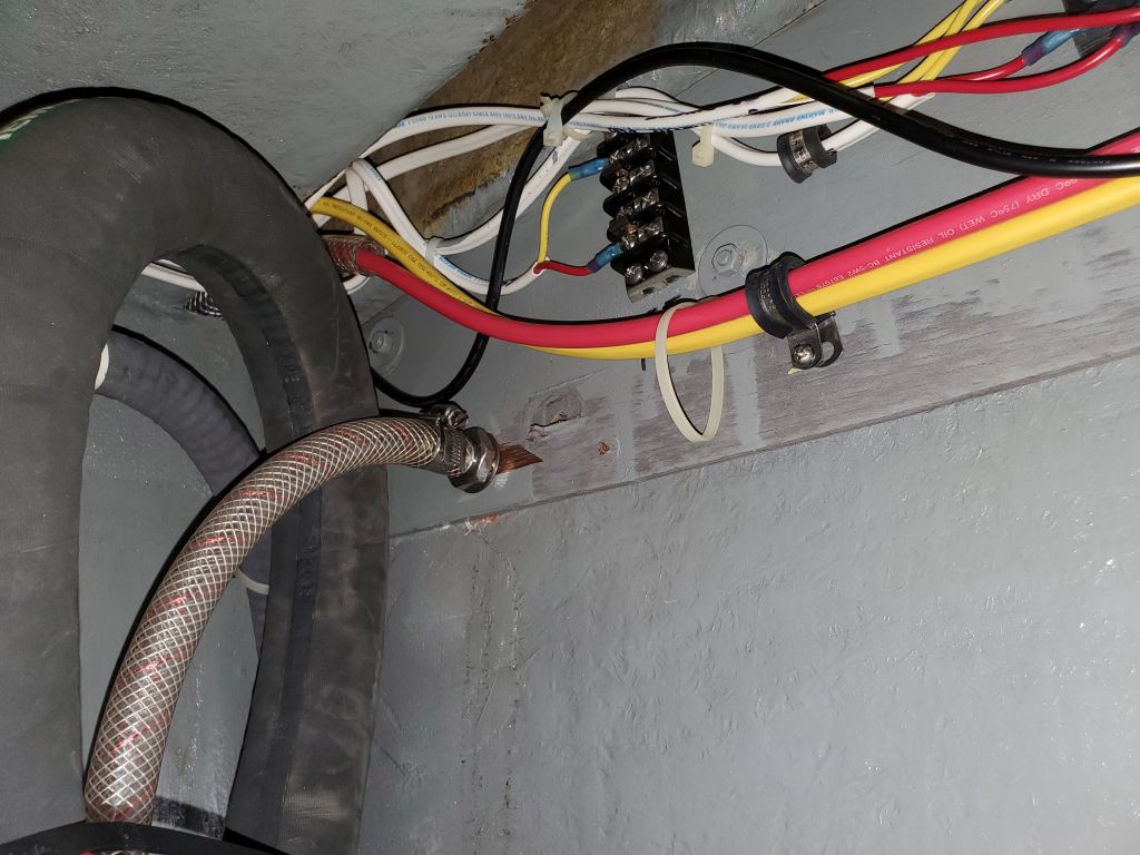
To finish off what I could of this installation for now, I installed a new discharge hose from the pump to the existing, and nearby, loop that led to the overboard discharge through hull. The proximity of the two connections required a hose loop to accomplish; the hose threading the needle through the loop is the actual and original discharge line from the toilet, which I would later connect to the inlet of the new tank once it was installed.
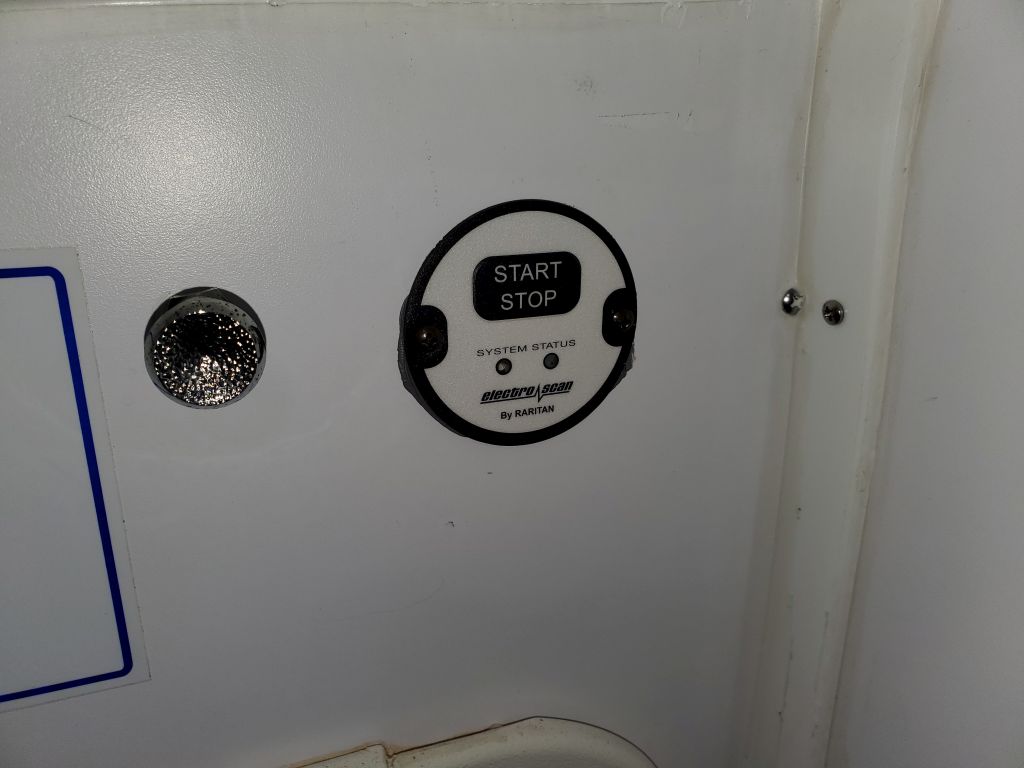
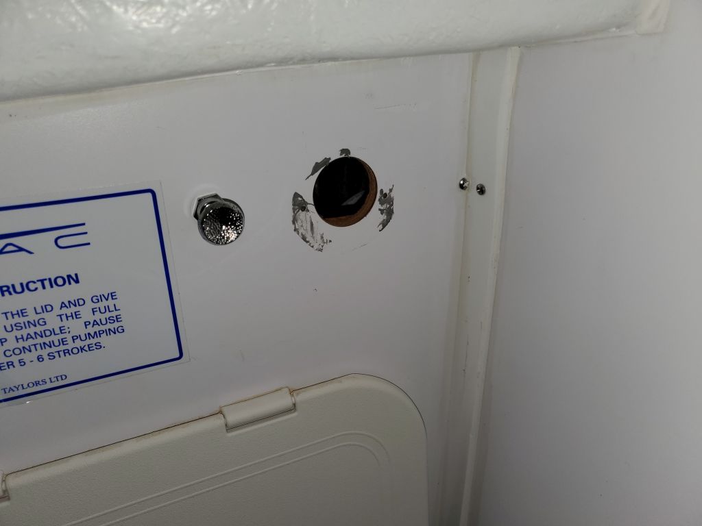
Meanwhile, while working in the head space I took care of a couple smaller removals. First, I removed the small control panel from the old electric head treatment system, leaving a 1″ hole in the bulkhead that I’d cover with something or other for cosmetic purposes in due course. I also removed the associated cabling that had led to the control box that I’d removed along with the old holding tank previously.
Because the owner wanted a different type of through-hull vent for the new tank, I also removed the old vent hose and vent fitting from the hull, which was located in the space behind the head panel. I’d replace the fitting and hose in the near future.

Total time billed on this job today: 4 hours
0600 Weather Observation: 32°, cloudy. Forecast for the day: Becoming sunny, 37°