

November 23, 2020
Lively Heels Phase 3-3
Monday
Picking up where I left off, I continued the tine-consuming work of removing the components of the old heating system, still focused mainly on the wiring for now even as I absorbed the existing hose situation in person and determined how to proceed on that front.
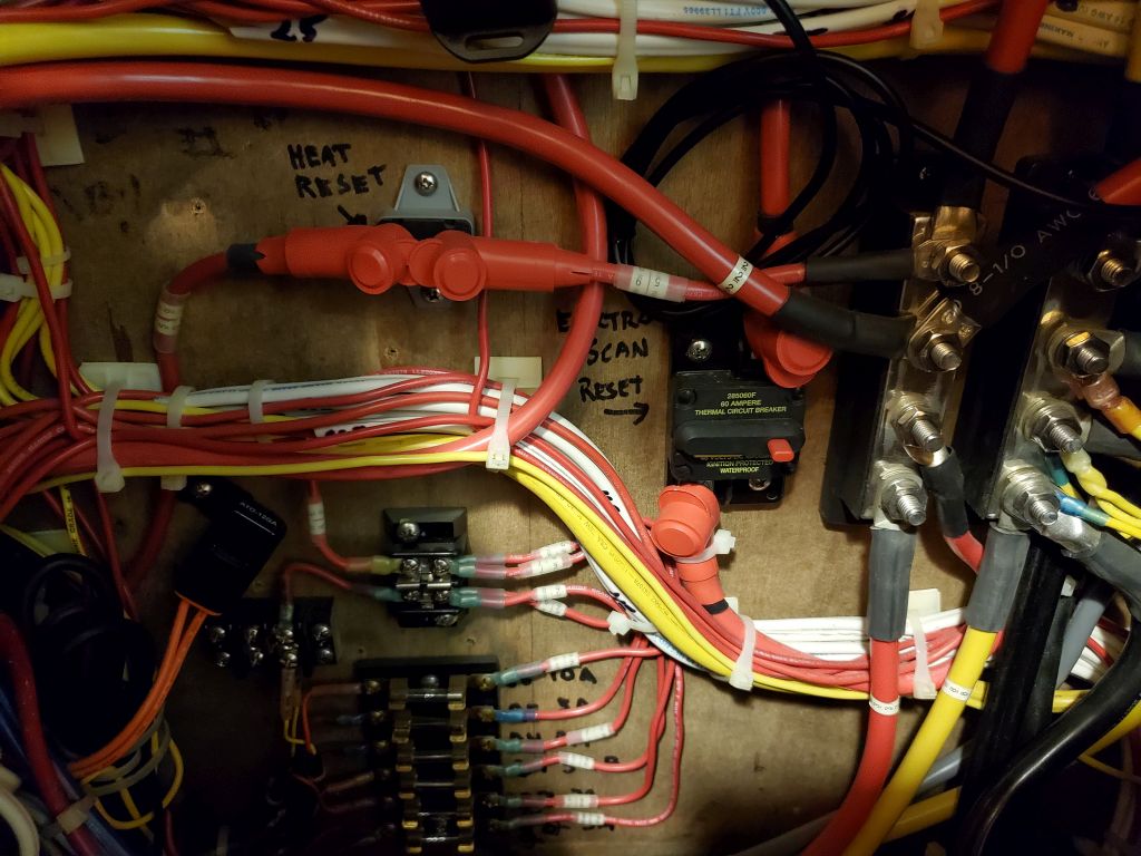
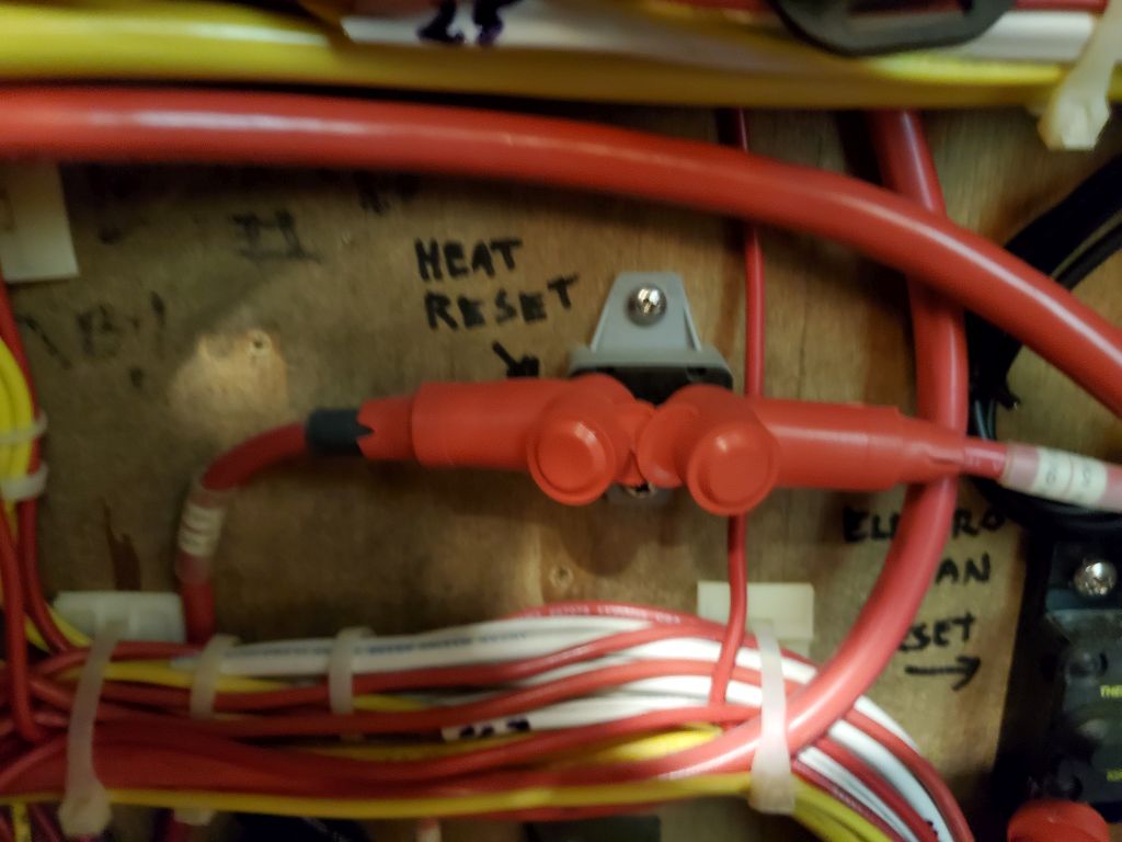
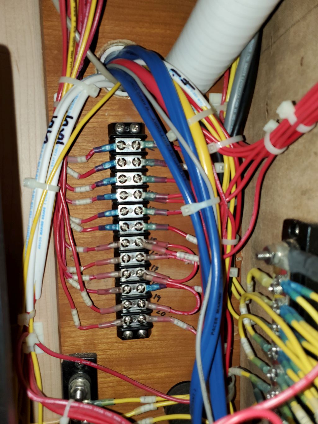
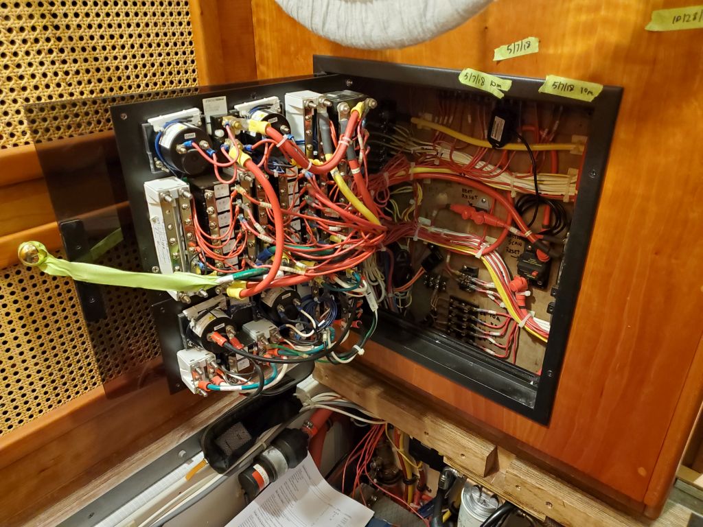
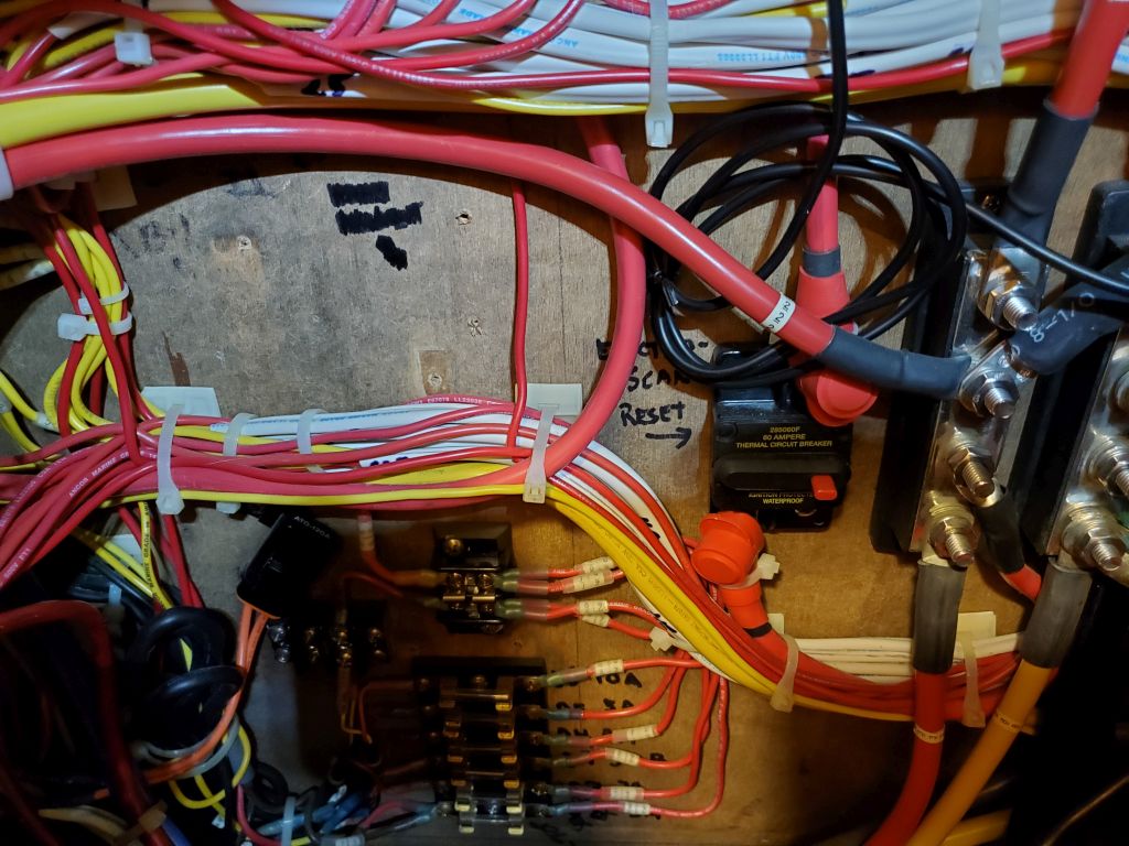
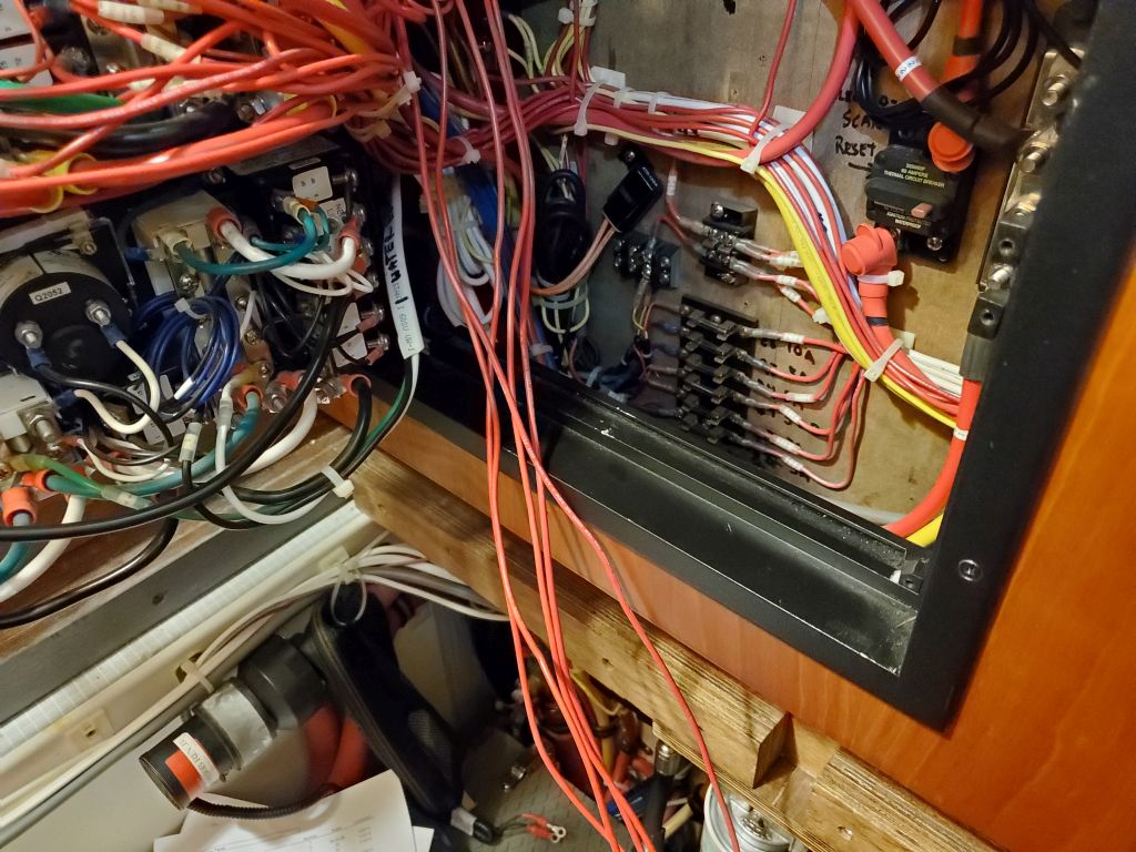
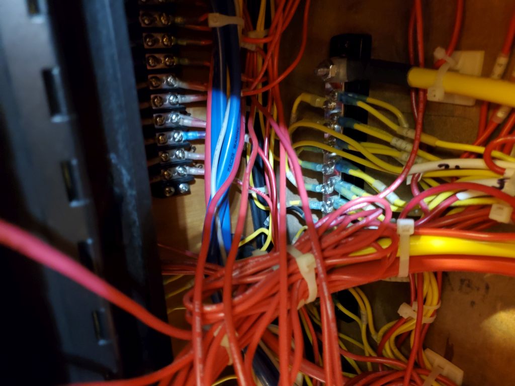
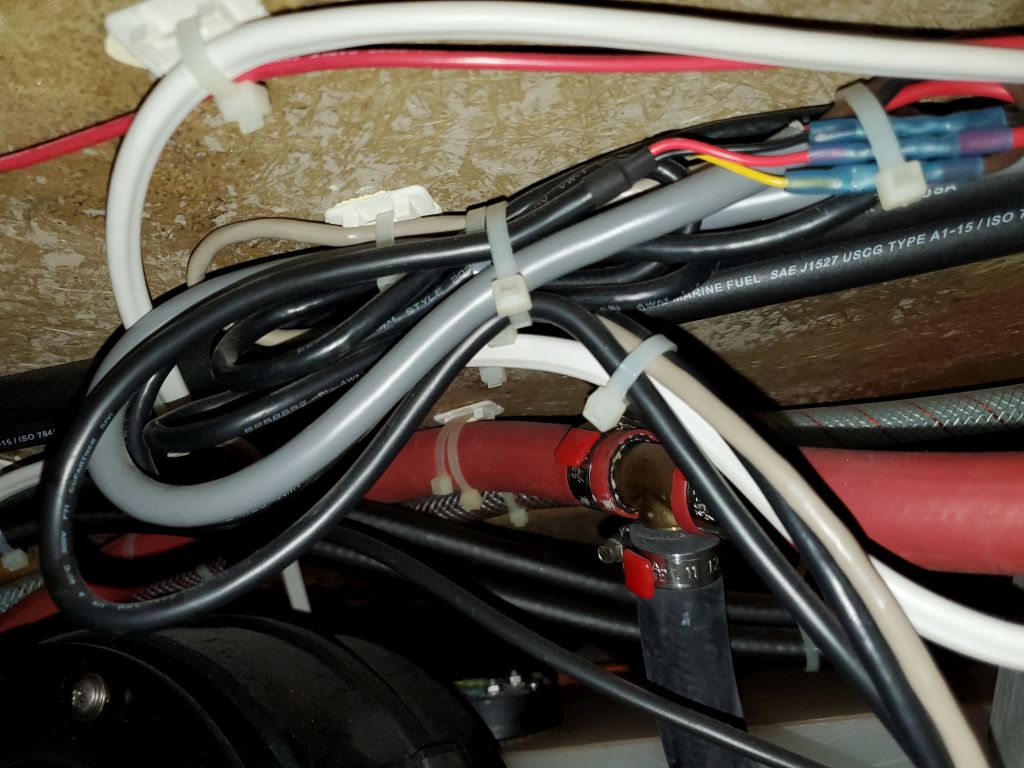
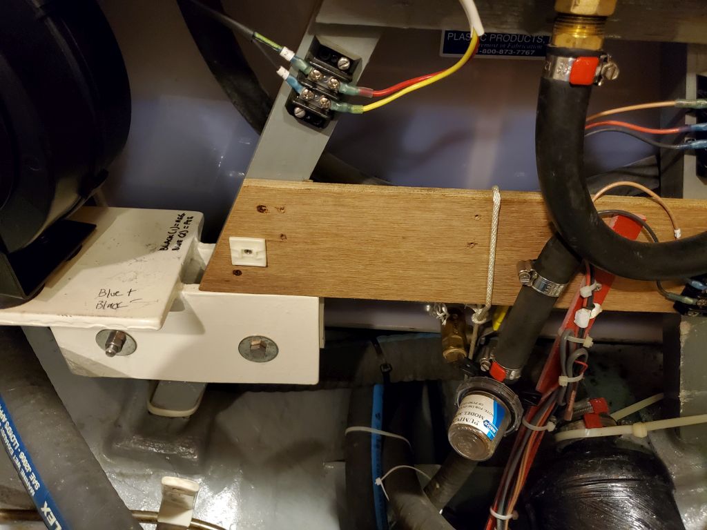
There were 6 or 7 wires I’d removed from the main heating control board in the engine room earlier, and now I had to pull them back into the console and eventually remove them entirely. This took quite a bit of time since I had to determine their paths, and carefully remove various wire ties and cable clamps to release the wires, before finally tracing them to their ultimate connections, which in this case were mainly on a terminal block on the port side of the console, though two now-unneeded wires led to the thermostat in the main cabin. I consulted and modified as I went a wiring list I’d made at the time of installation to ensure the numbered wires I was removing were the right ones, and that they were removable without affecting anything else.
Access was tight, as always, and these wires had been installed very early in the original wiring process, starting in 2012, so they were pretty buried and contained within several ever-growing wire bundles, but at length I removed them all cleanly, along with the main circuit breaker and power cables for the defunct boiler. The old wires joined the control box and parts of the fuel system that I’d removed before.


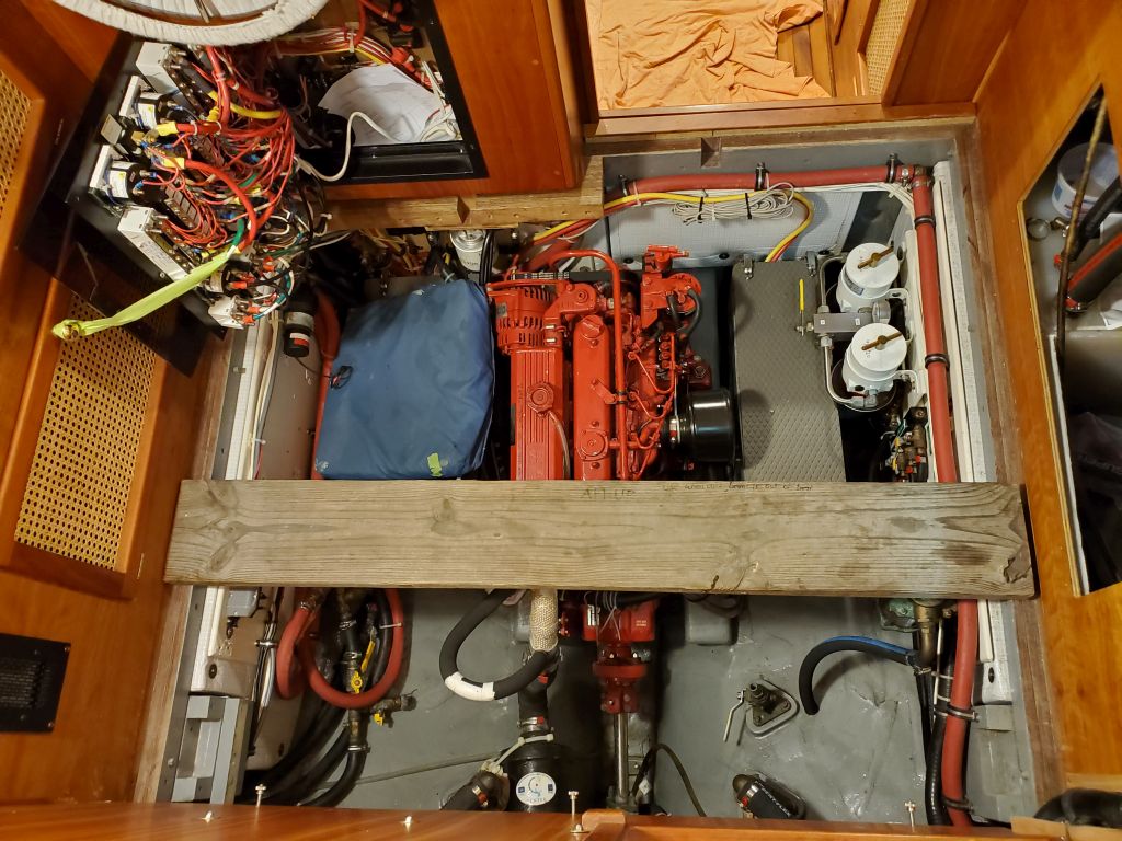
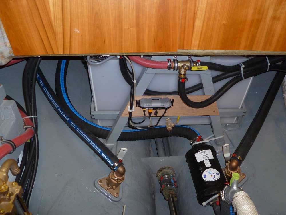
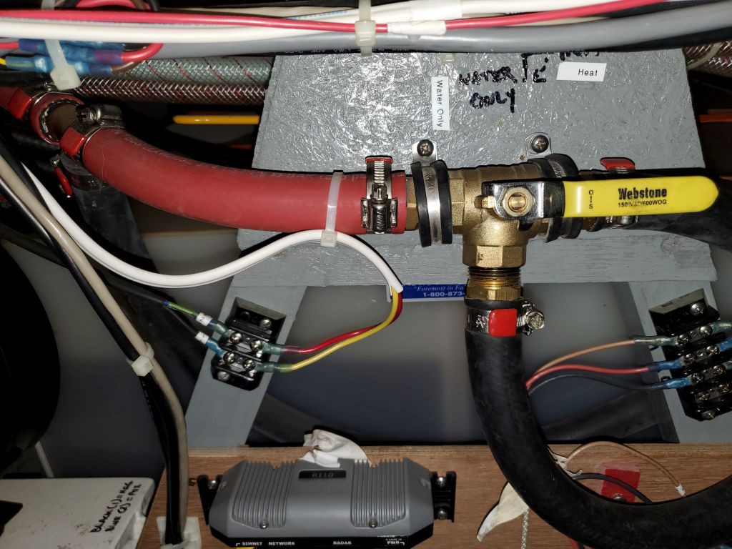
Meanwhile, I continually assessed the heating system hoses which the owner had temporarily jury-rigged and connected after removing the boiler earlier. The original system had been configured to allow heat and domestic hot water firing by the diesel boiler (now removed), or by the engine’s coolant bypass system, and for the moment this meant that the engine could and did still work to heat the system by way of a slim heat exchanger located down behind the port battery box. Under this setup, the engine coolant warmed the heating system coolant (currently an entirely independent system), and a circulator pump moved that coolant through the system fixtures, which included the domestic water heater and two cabin heaters.
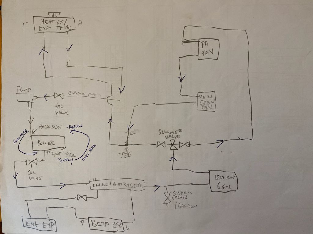

The project goal was now to simplify as much as possible the existing setup. One option was to keep things more or less as is, which would be more straightforward in terms of actual work now, but would have only a minimal effect on removing excess hose and equipment. The electric circulator pump would still be required in this scenario, and if we went this way I planned to wire it through a new switch for ease of operation. There was still an opportunity to clean up and somewhat simplify the existing hoses, but they’d mainly be required and stay in place as is.
A second option that could greatly simplify the system was to plumb the engine’s coolant bypass (currently used only to run through the heat exchanger as indicated in the above schematics) directly into the heating system, using the engine’s coolant pump to circulate through the water heater and two fan heaters. I contacted a knowledgeable source at Beta Marine about this to confirm, since I was unsure about the ultimate capacity of the engine’s coolant pump. Under this scenario, I could remove a large portion of the old system, including hose runs, a separate high-mounted coolant tank, and the heat exchanger on the port side, and this would lead to a greatly simplified plumbing situation. Shutoff valves in the coolant bypass (already in place in the existing system as well) could isolate the heating runs if needed or desired. This option would require a substantial amount of work now, but the boat might benefit from the greater simplicity in the future.
For the moment, I didn’t know which way we would ultimately choose, and other considerations remained, so I wasn’t ready to start the work just yet.
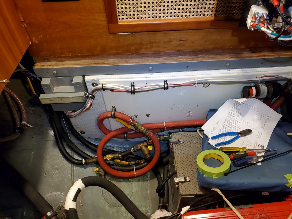
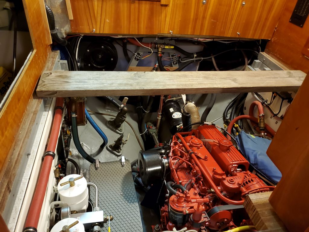
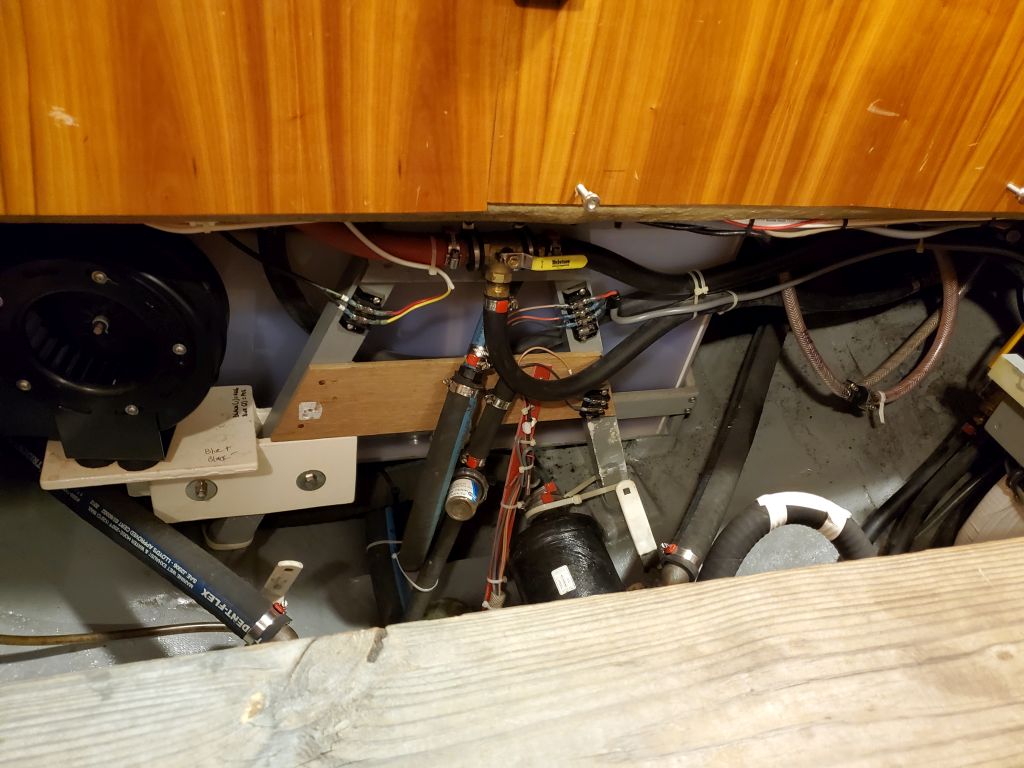
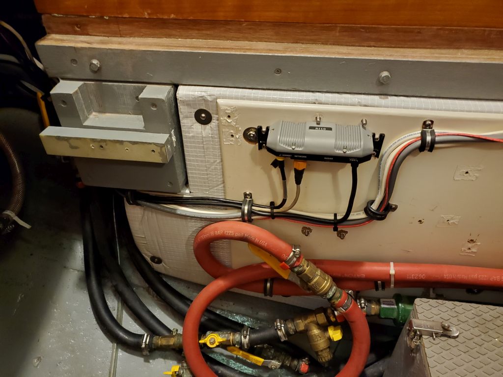
In the meantime, I addressed another of the owner’s concerns. Because of the radar’s location on the mizzen mast, back in the day during the original project I’d located the radar network interface and connection box at the aft end of the engine room, where it was convenient to the radar’s cable that had to be removed each winter when the masts were unstepped for storage. The first picture below is from the original installation of this interface box on 9/9/2012; the other ones from now.
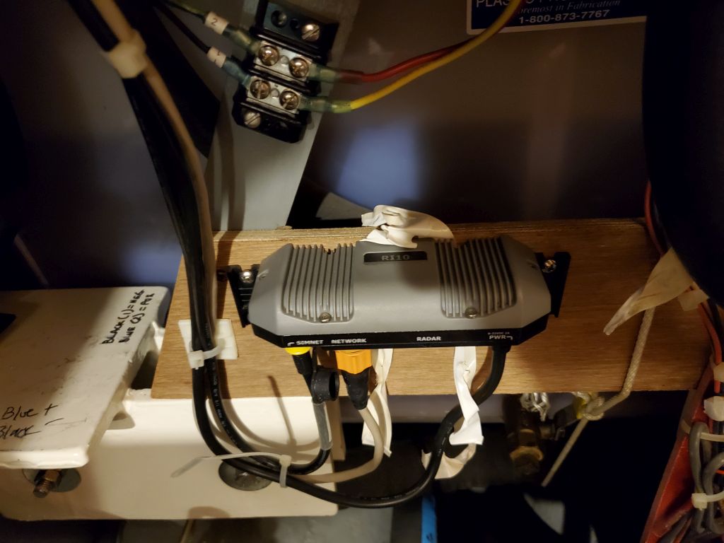
This location was fine except it was difficult to reach when the engine room was fully put together with the removable after support beam in place (not shown in these photos). The owner indicated that for such a simple and necessary job twice per year, it was unnecessarily difficult to access the box, since removing the heavy support beam also required removing all three pilothouse floor panels completely. So he requested if I could find some other location for this interface that would be easier to connect and disconnect each time.
I wasn’t immediately sure what I could do with the box, but I determined there was ample excess wiring tied up nearby, which at least offered some options. After releasing the wire bundle, and detaching the box itself, I considered a few different locations, none of which were suitable for one reason or another (impractical; wires too short; no room to mount the box; etc.) before eventually zeroing in on the mounting panel on the port side of the engine room, where the boiler and its related components had been located. With some minor rerouting of the existing wire bundle that I’d only just remounted earlier in the day, there was an open and convenient space for the radar network box, and plenty of cable length to lead it there.
This location would be much easier to connect and disconnect, though the radar wire itself, which led through the cockpit deck just aft of the pilothouse, would have a longer run to reach it, but I checked the original photos and logs from when I installed the radome on the mizzen in 2015, and determined that there was plenty of cable length available for this, so I went ahead with the move. This had the benefit of enhancing the bundled cable runs around the aft corner of the engine room from how they’d been originally.

Total time billed on this job today: 5.75 hours
0600 Weather Observation: 48°, showers. Forecast for the day: Heavy rain, 53°