

February 26, 2018
Jasmine 59
Monday
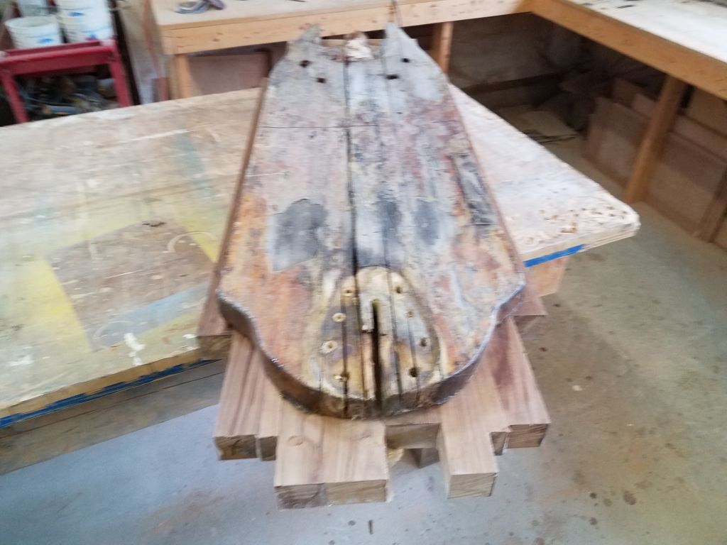
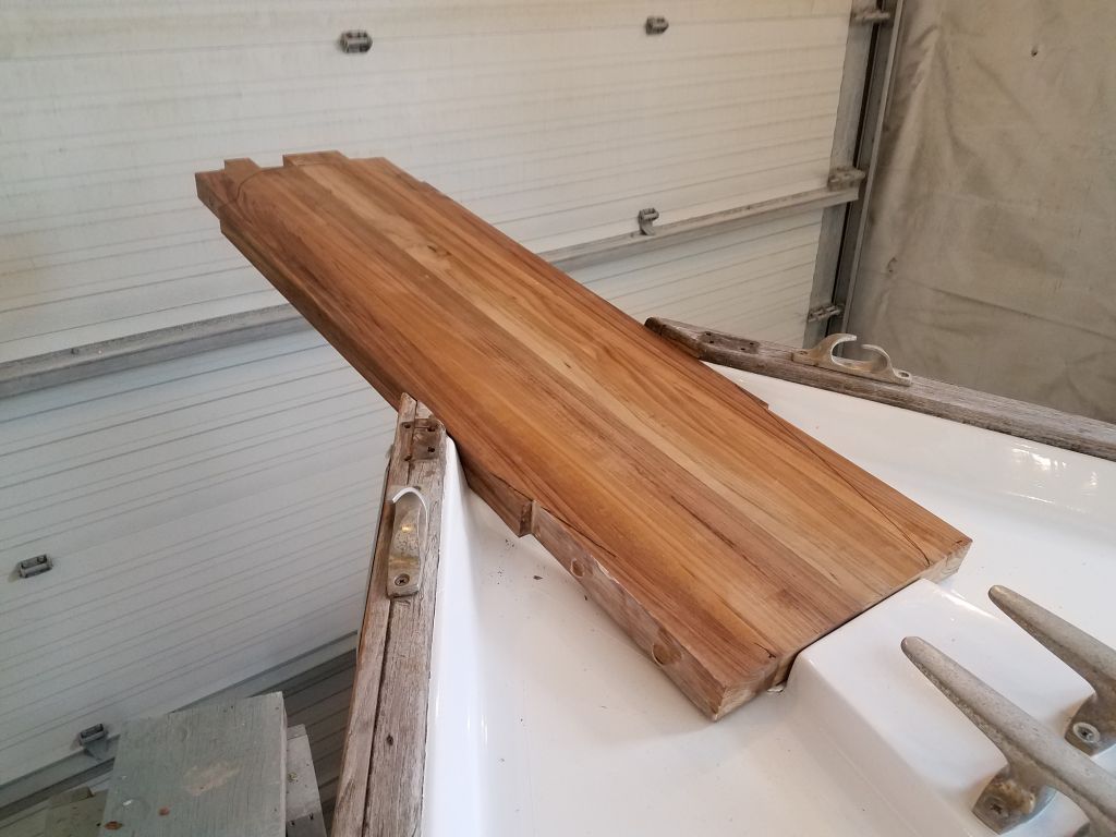
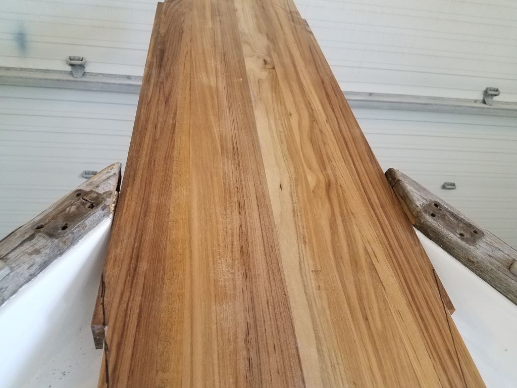
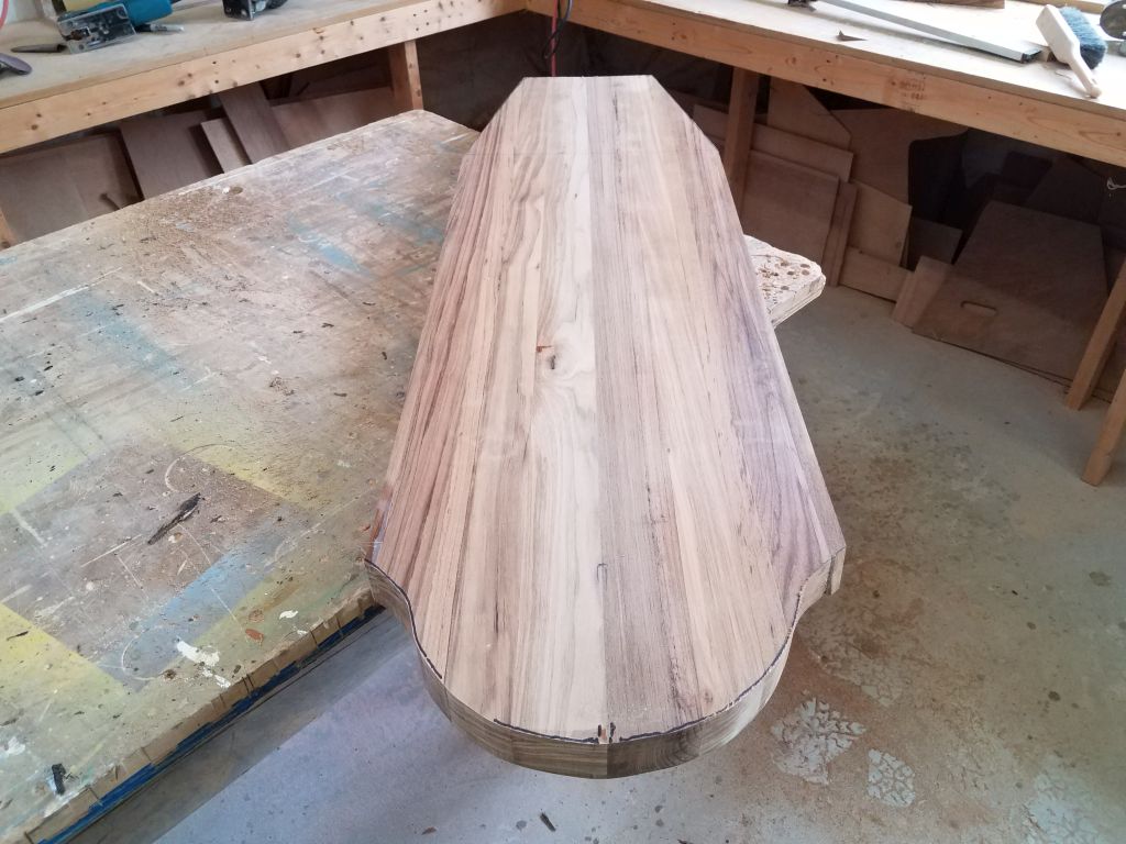
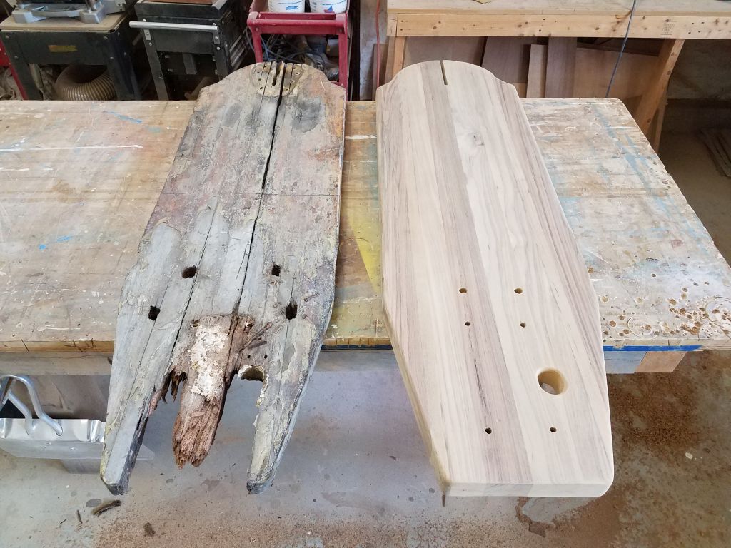
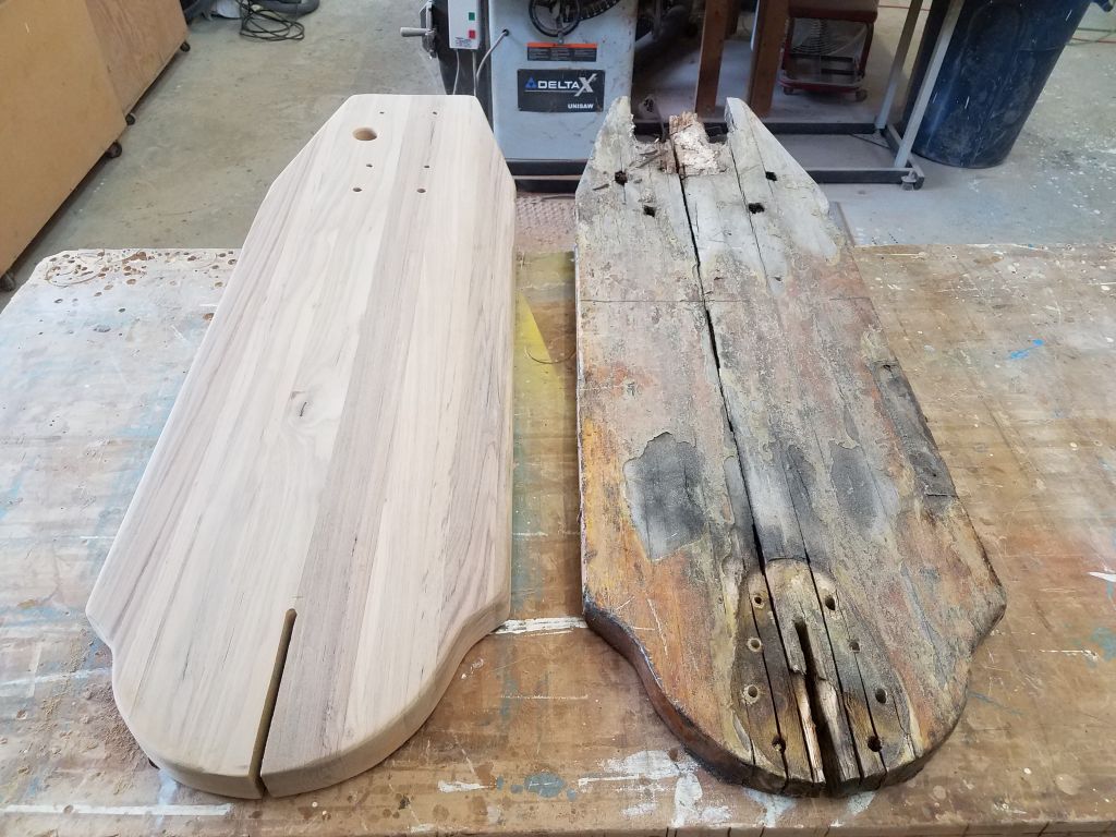
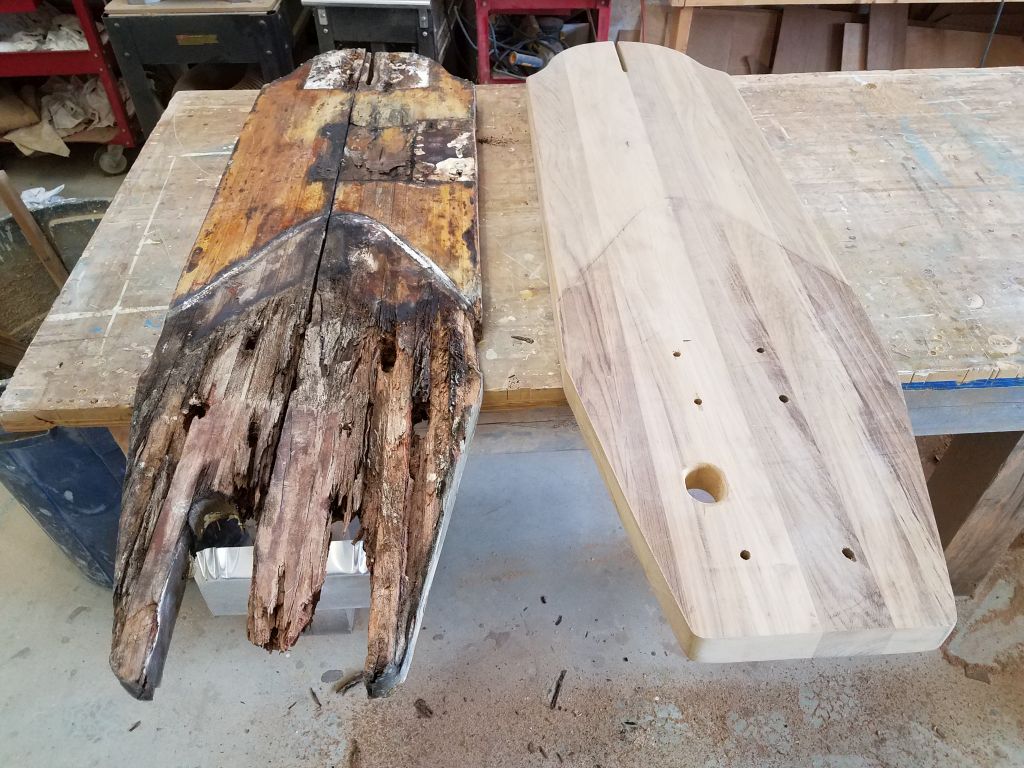
I unclamped the glued-up bow platform and sanded away any excess epoxy from the top and bottom surfaces. Then, using the old platform as a guide, I trimmed the two long sides till they were close to the final width, then trimmed the after edge square. The old platform was in such bad condition that I didn’t want to entirely rely on using it as a template, or even on measurements, so I erred on the side of caution and kept the new blank a bit wide for now–so wide that it didn’t yet slip into its opening between the bulwarks.


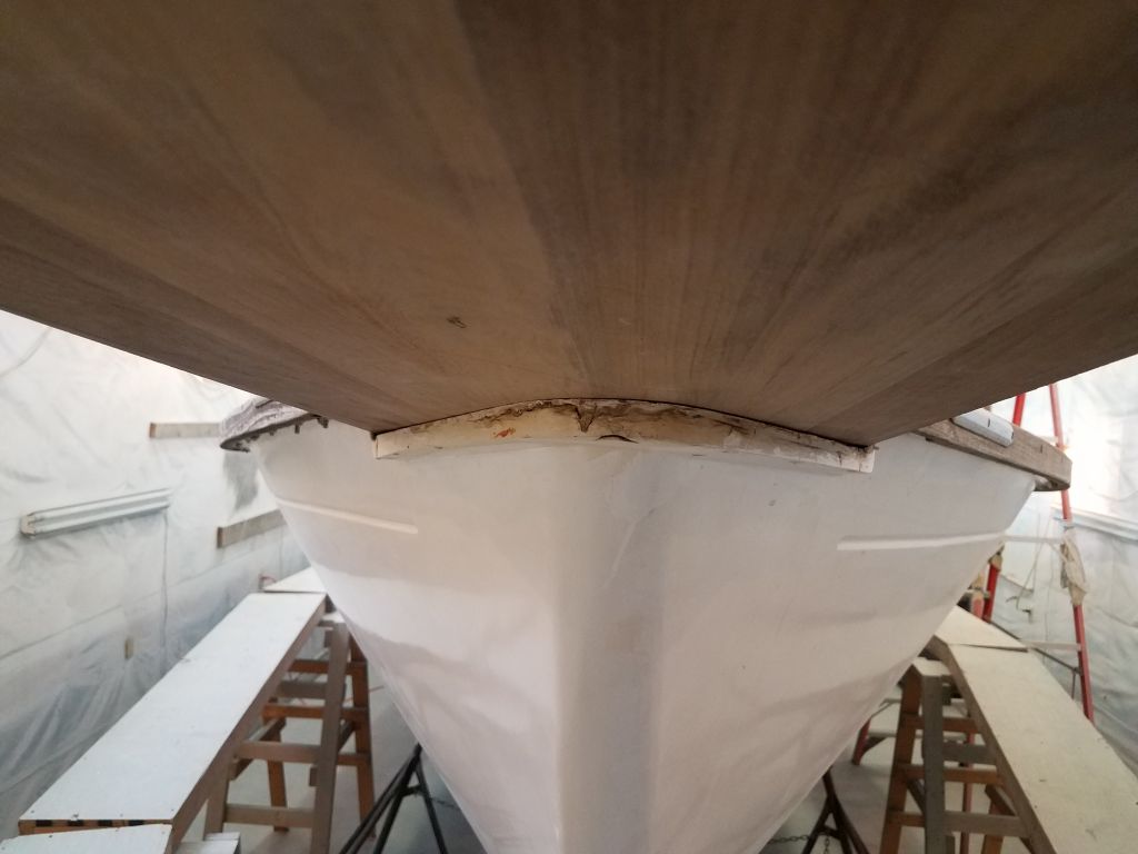
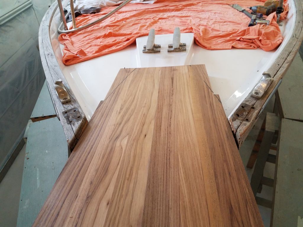
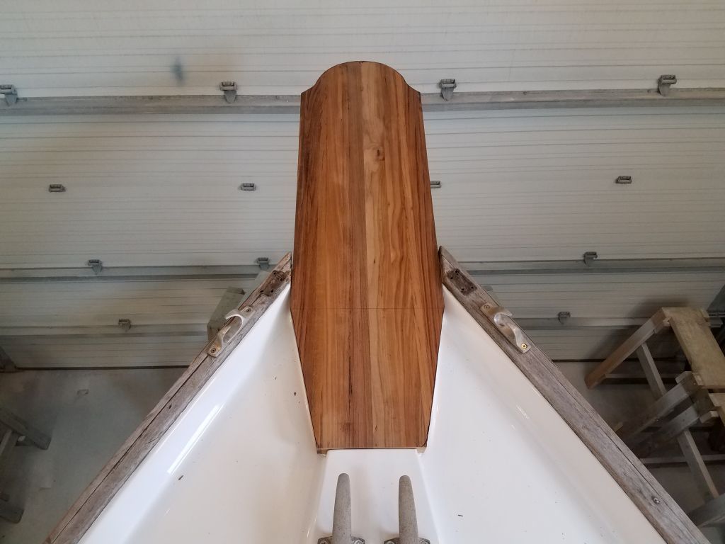
After measuring the opening and comparing the width of the platform visually, I felt comfortable trimming the blank down to size, taking another 1/8″ off each side, and now the blank fit properly on the bow. I’d left the blank rectangular for now, but with it in place I could make some reference marks for the angled cuts that would taper the aft end down to meet the forward edge of the raised cleat platform just behind.
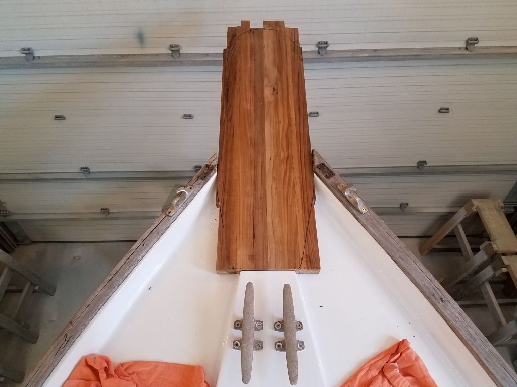
Back down on the bench, I made those cuts, and also used the original platform to layout the curves at the forward end so I could cut that as well.
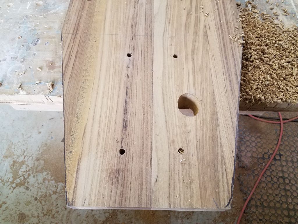
While the platform was in place this time, I went belowdecks to the chainlocker beneath and made some marks up through the existing holes for the windlass bolts (4) as well as the larger hole for the anchor chain. Although I had some paper templates of these locations, it never hurt to use reality as a guide instead.
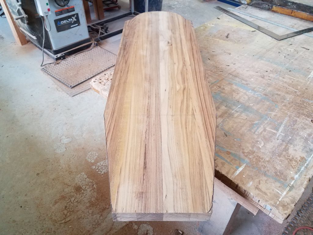
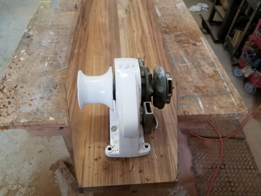
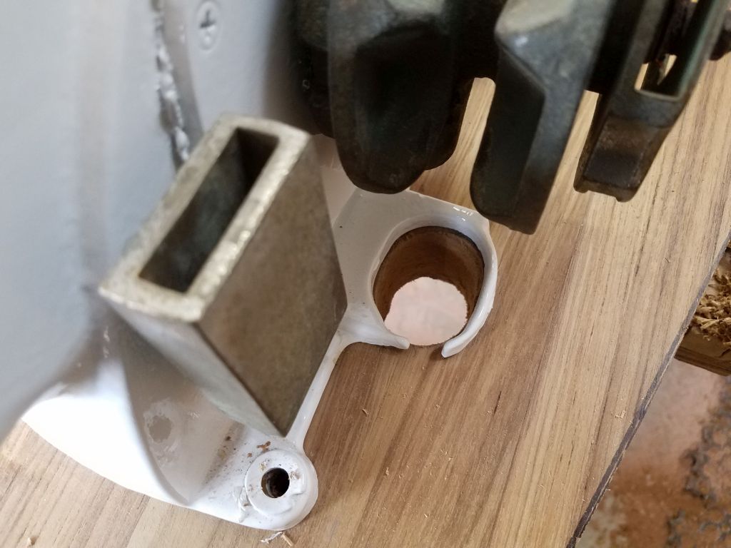
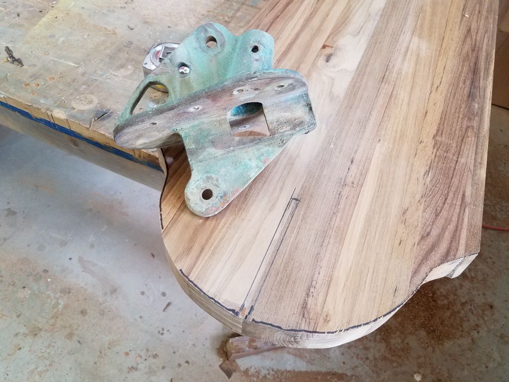
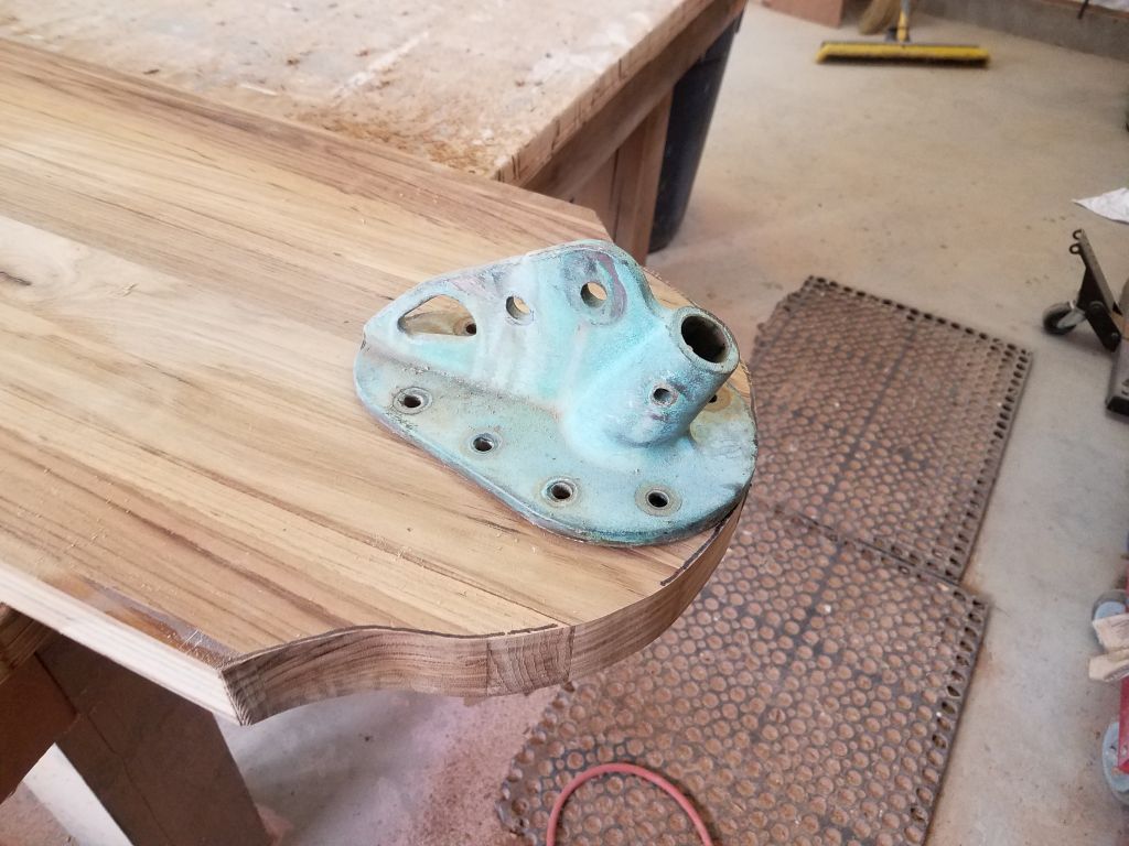
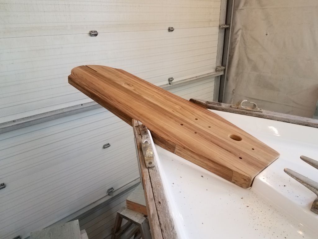
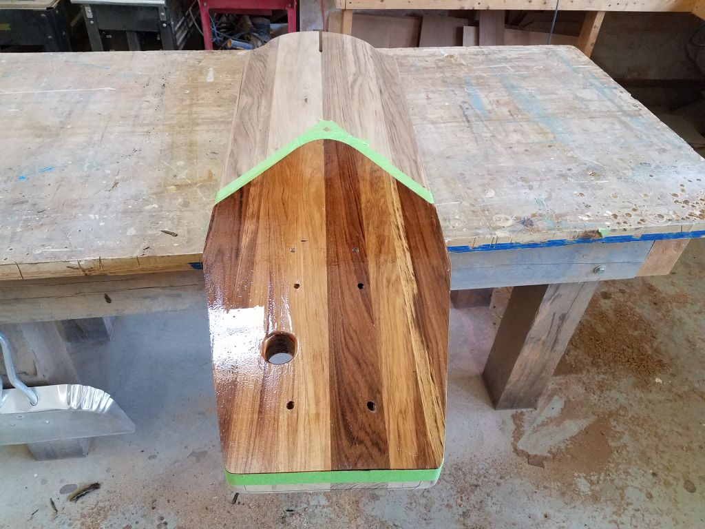
On the bench once more, I drilled 1/8″ pilotholes through each of my marks on the bottom, thus locating them on the top surface of the platform, and then placed the windlass over the holes to finalize the layout and drill the bolt holes and chain hole as needed. Meanwhile, at the forward edge of the platform, I laid out and cut the slot to accept the bronze stem fitting, which I wouldn’t permanently install till the platform was in place in order to save weight. One more test fit on the boat, and I was ready to finish up the platform.
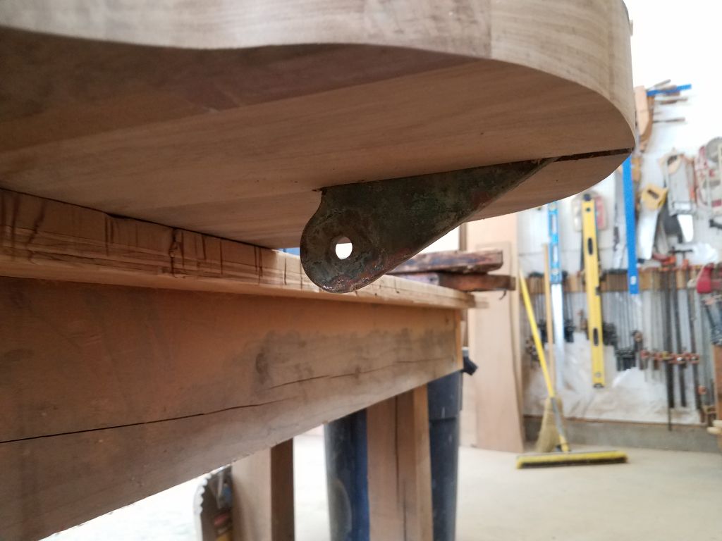
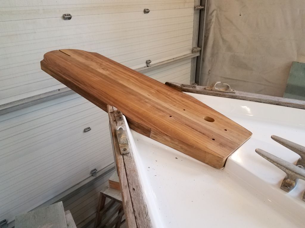
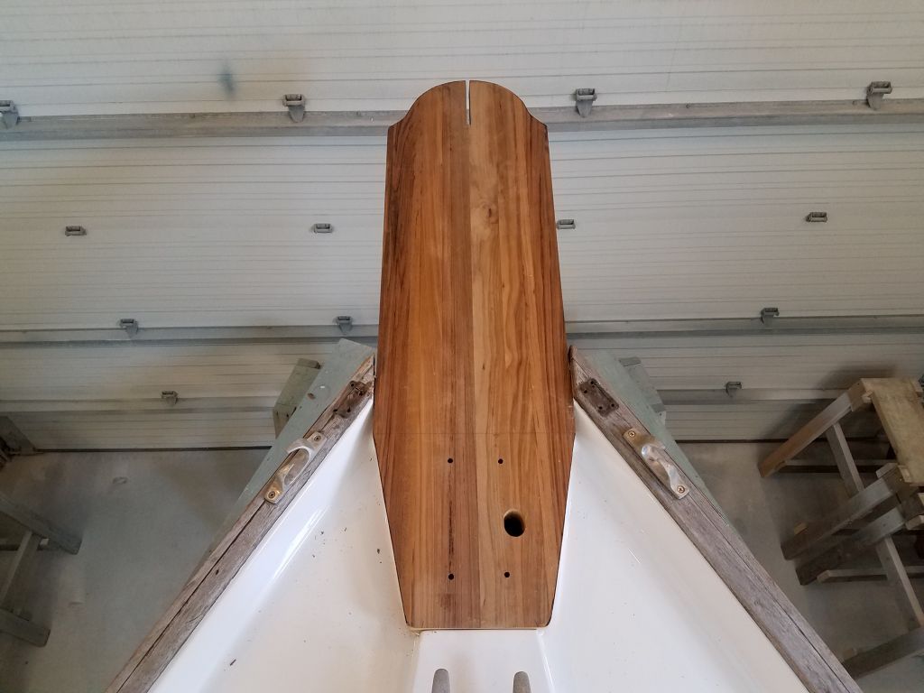
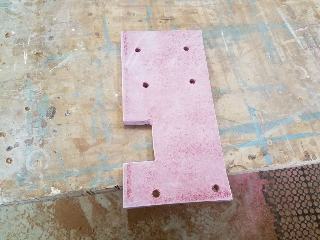
I rounded over various edges of the platform, both on the top surface (everywhere but the short sections where the platform lay against the bulwarks) and bottom edge (the protruding portion beyond the stem), and sanded the whole platform clean and smooth. Meanwhile, I prepared a 3/4″ fiberglass backing plate for both the anchor windlass and the platform itself, and laid out another pair of bolt holes for securing the platform, located just forward of the windlass. The six bolts, including four for the windlass, would be sufficient to secure the platform along with adhesive sealant.


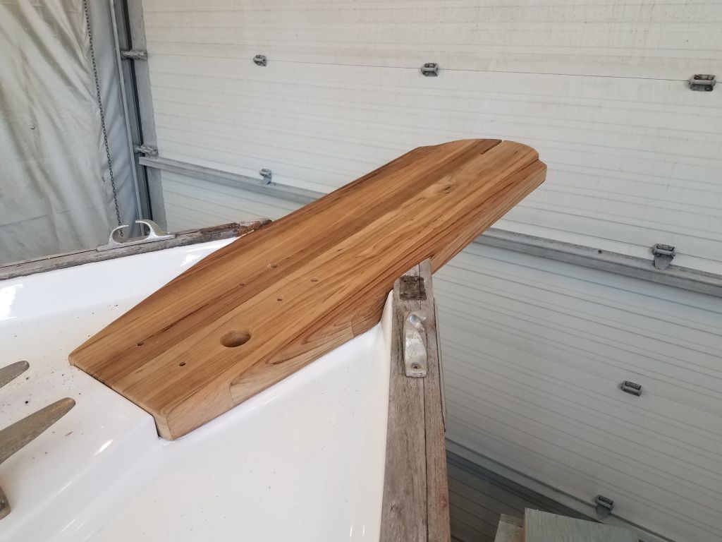
Before installation, I marked off and epoxy-coated the faying surface of the platform for protection and to promote good bonding, leaving this to cure overnight. I had the long bolts needed for the platform installation on order, and would complete the installation once they arrived.
While I had sanding tools going, I cleaned up the new mast step riser that I’d laminated earlier, removing excess epoxy from the joint and smoothing the whole thing as needed to prepare for primer and paint.

Preparing for the electrical installation ahead, I began by installing wire tie mounts at intervals along the known wire runs–that is, along each side of the cabin under the gunwales and through cabinetry as needed. I used adhesive mounts that experience had taught are best left along for a day before putting them to use, despite claims of fast curing for the adhesive. Most of the mounts landed on the gelcoated liner throughout the cabin, but even so I lightly scuffed each location and cleaned with solvent before applying the adhesive, as the fantastic bonding claims of this adhesive had long proved themselves caveat-worthy.
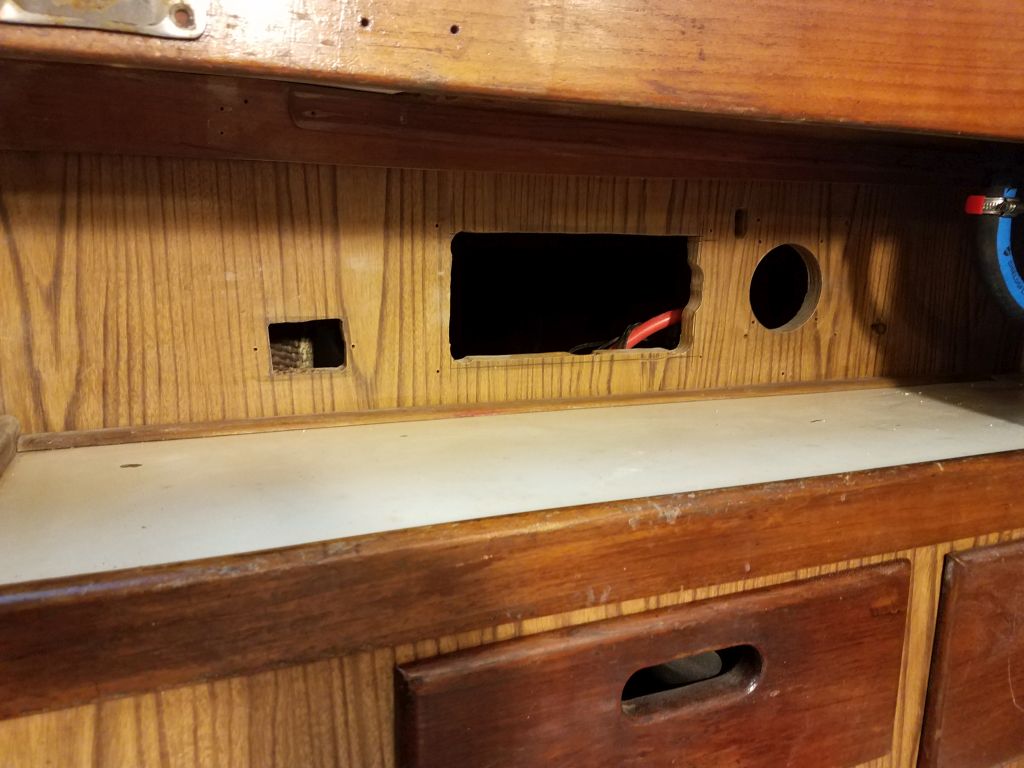
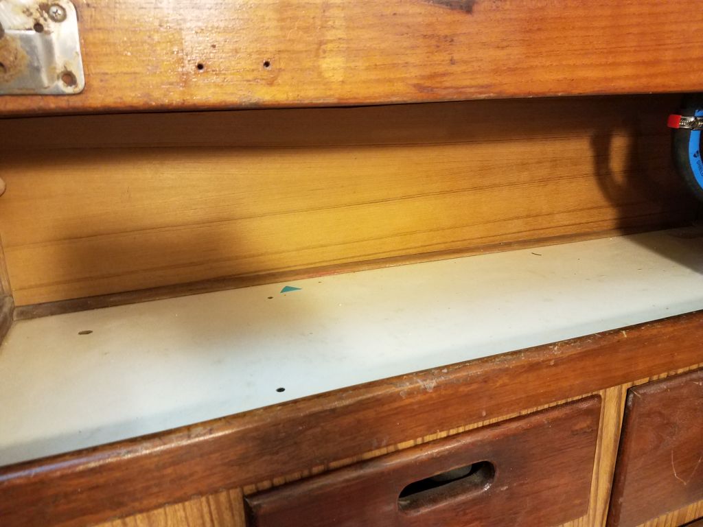
The owner wanted to centralize the electrical panels and other controls in the long, narrow space under the port bridgedeck, which also had convenient and direct access to the batteries and related components behind. This space had apparently contained a panel and other installations previously, and had some large holes already in place. Since it was a tight and difficult space to work in, and to allow convenient and attractive layout of the various new components as well as cover the existing holes to give me the freedom of layout I wanted, I chose to prepare a simple cosmetic panel over the top, which I patterned to fit the slightly tapered space and cut from some leftover 1/4″ teak plywood I had on hand.

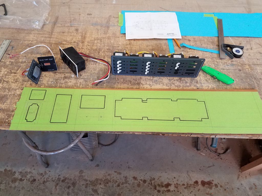
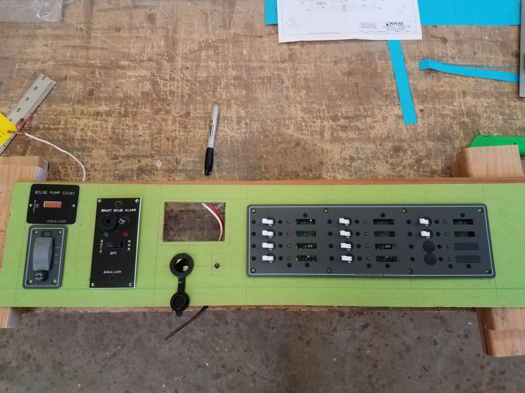
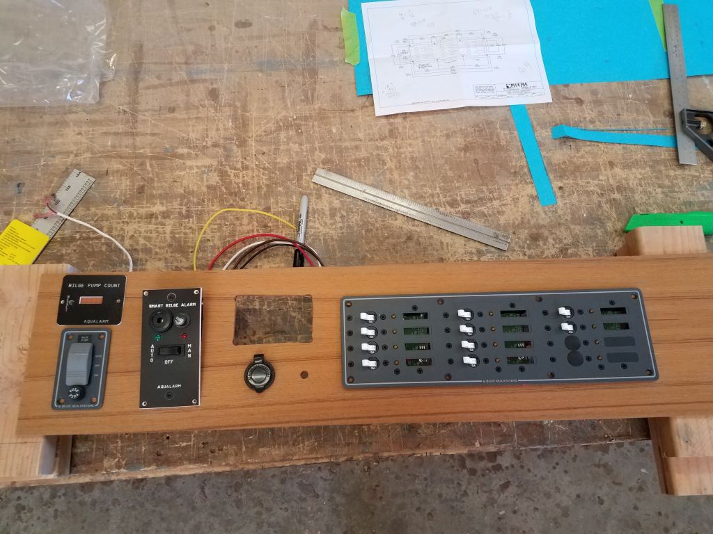
With the new face panel cut to fit, I had some fun laying out the various installations, which included the following:
- Bilge pump switch
- Bilge alarm panel
- Bilge pump counter
- 12-volt outlet
- Toggle switch for the tricolor/anchor light combo
- 12-position circuit panel
- Battery meter (not on hand, but I had the measurements for layout)
I covered the teak with masking tape to allow me freedom in drawing in the outlines of the components, since space was tight and I wanted it to look good. Through trial and error, and working around–while not specifically tied to–the location of the existing large opening in the bulkhead, I eventually came out with a layout that worked well in the panel, and made the cuts required to install the various devices. I’d use the face panel to lay out the cuts needed on the bulkhead itself before installation, but for now the day was over.
Total time billed on this job today: 7.5 hours
0600 Weather Observation: 33°, fog. Forecast for the day: Becoming sunny, highs in the 40s