(page 5 of 8)

Lyra 36

Thursday

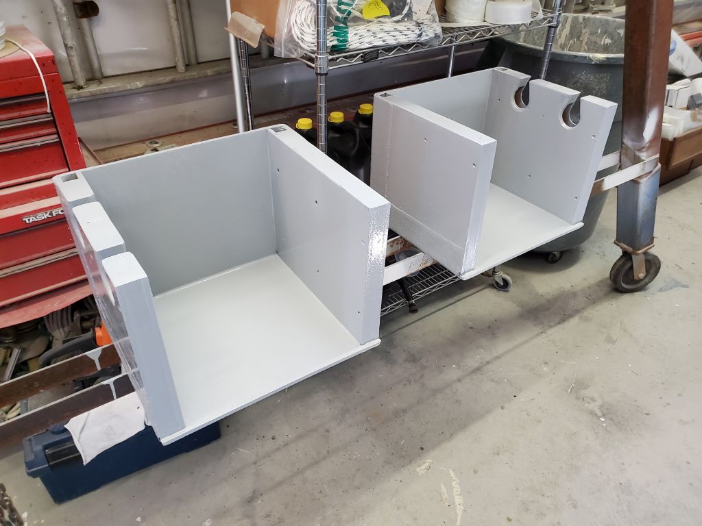
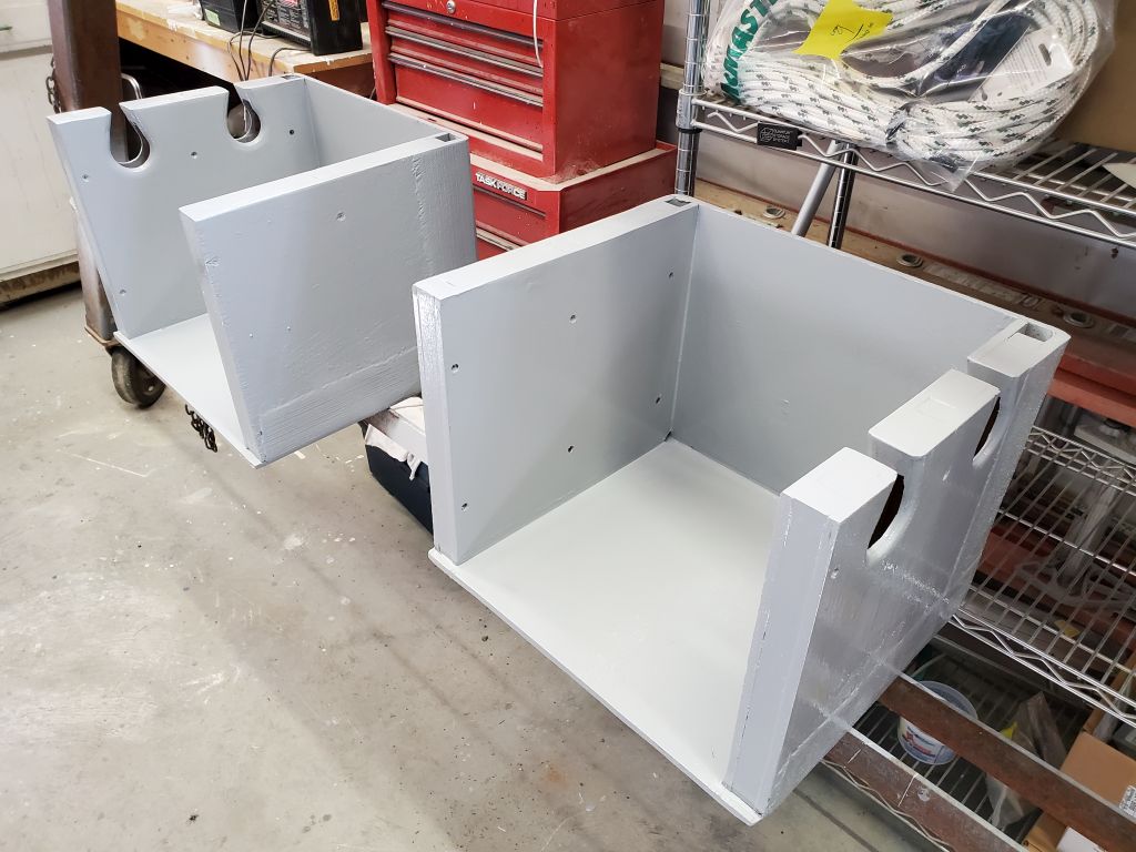
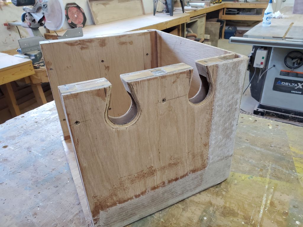
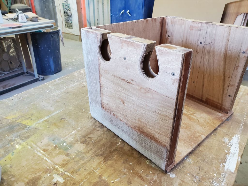
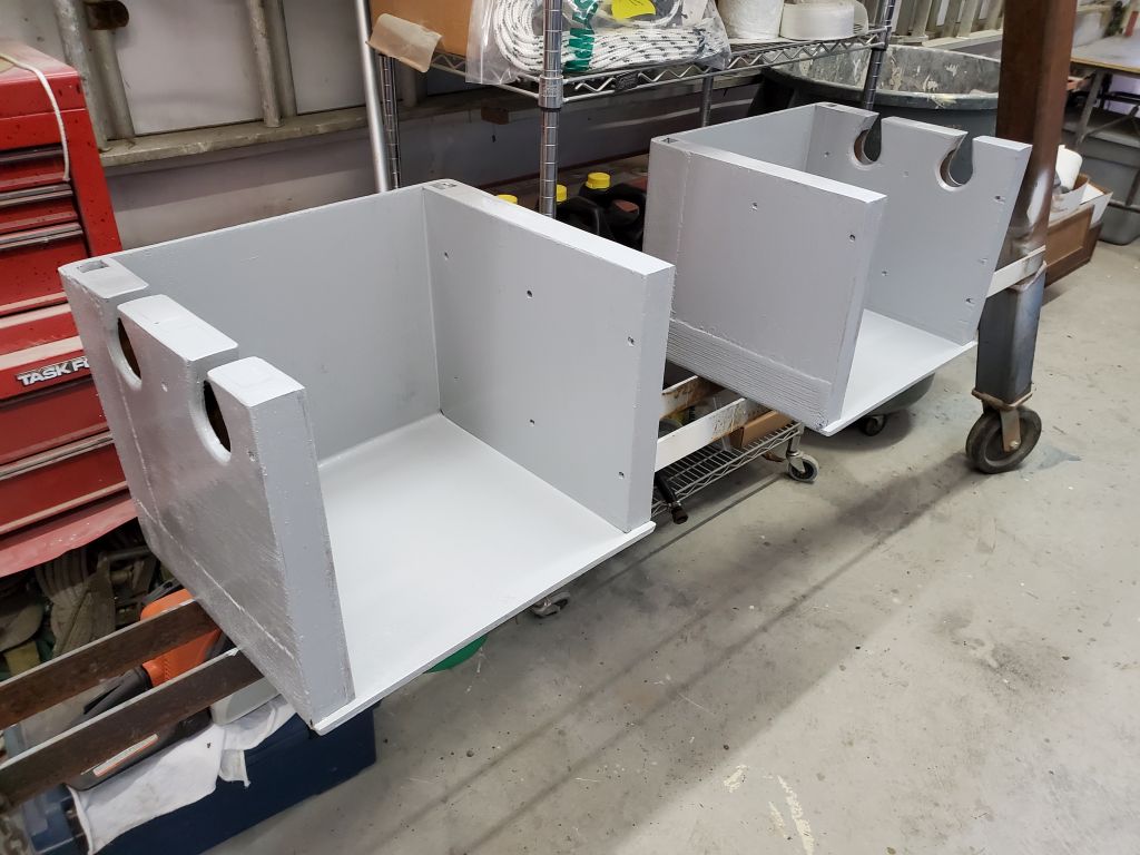
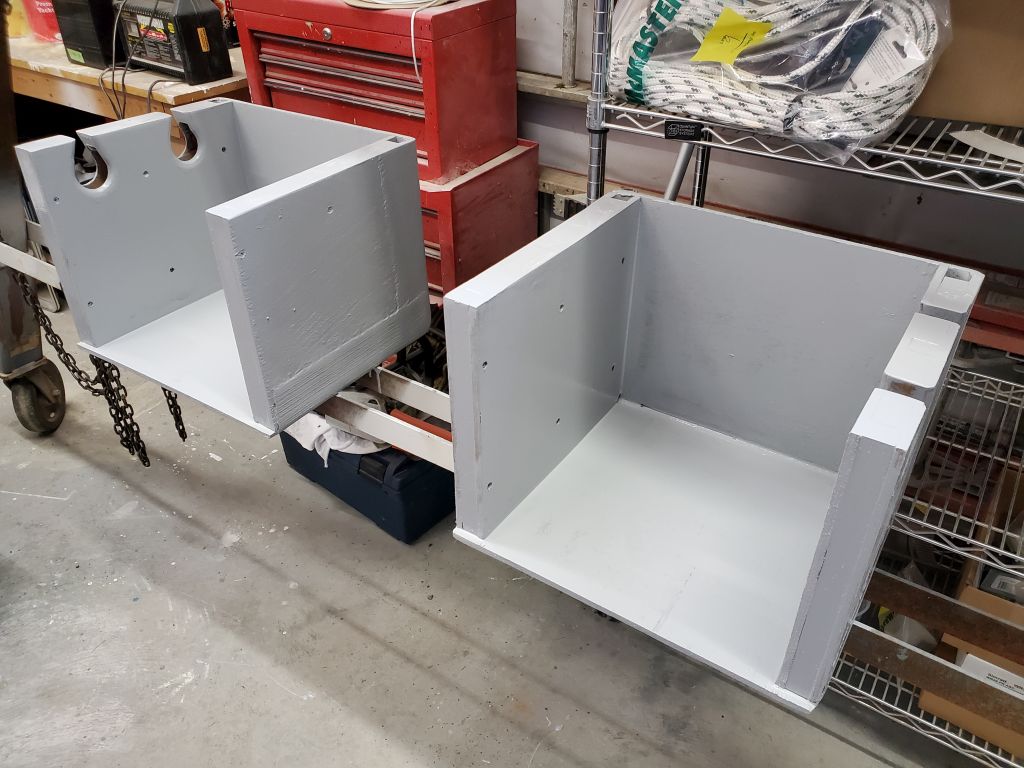
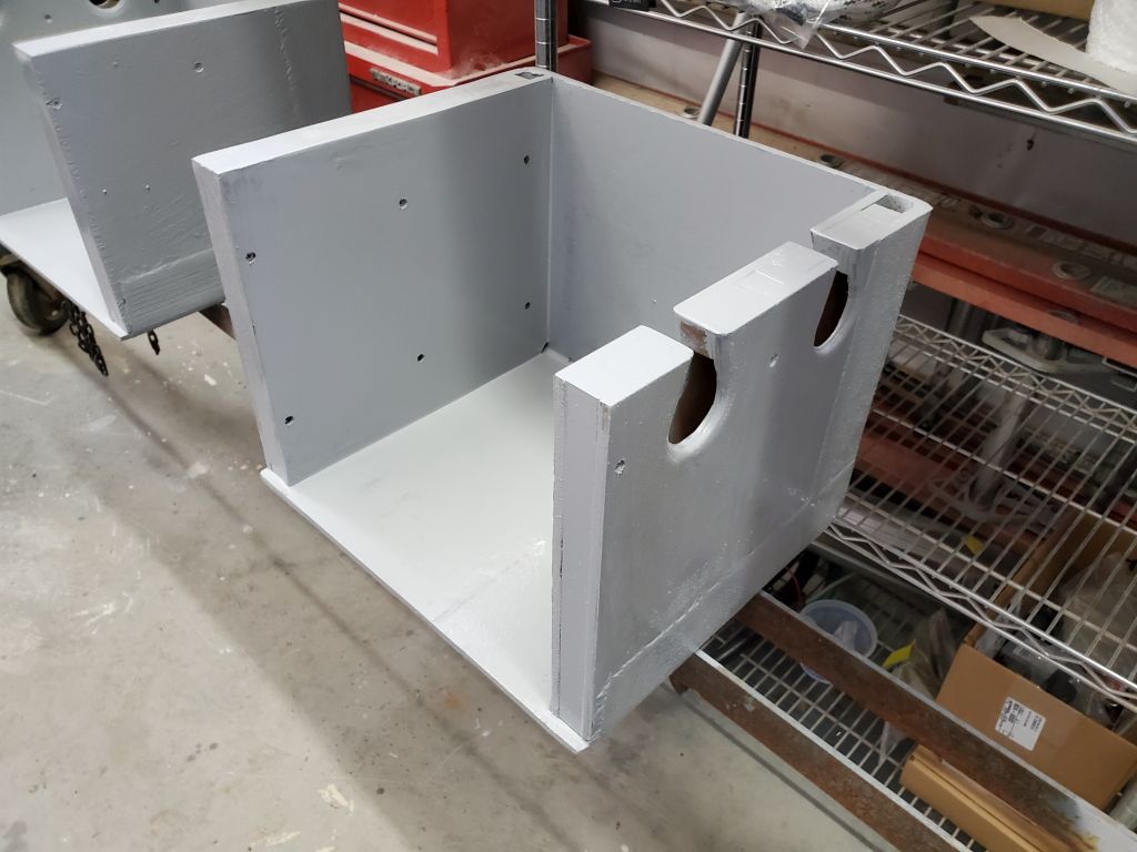
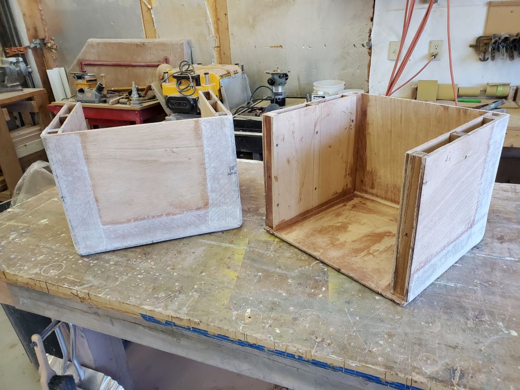
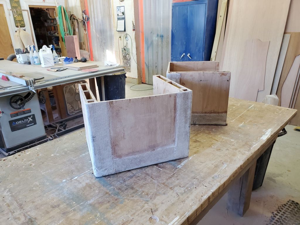
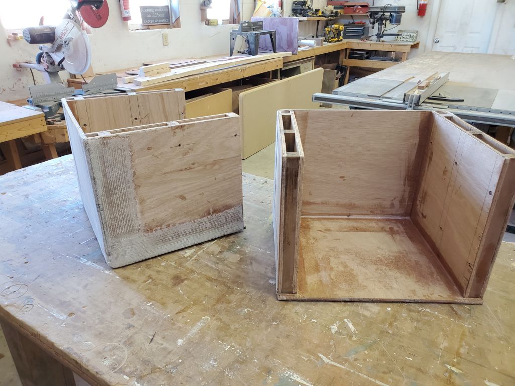
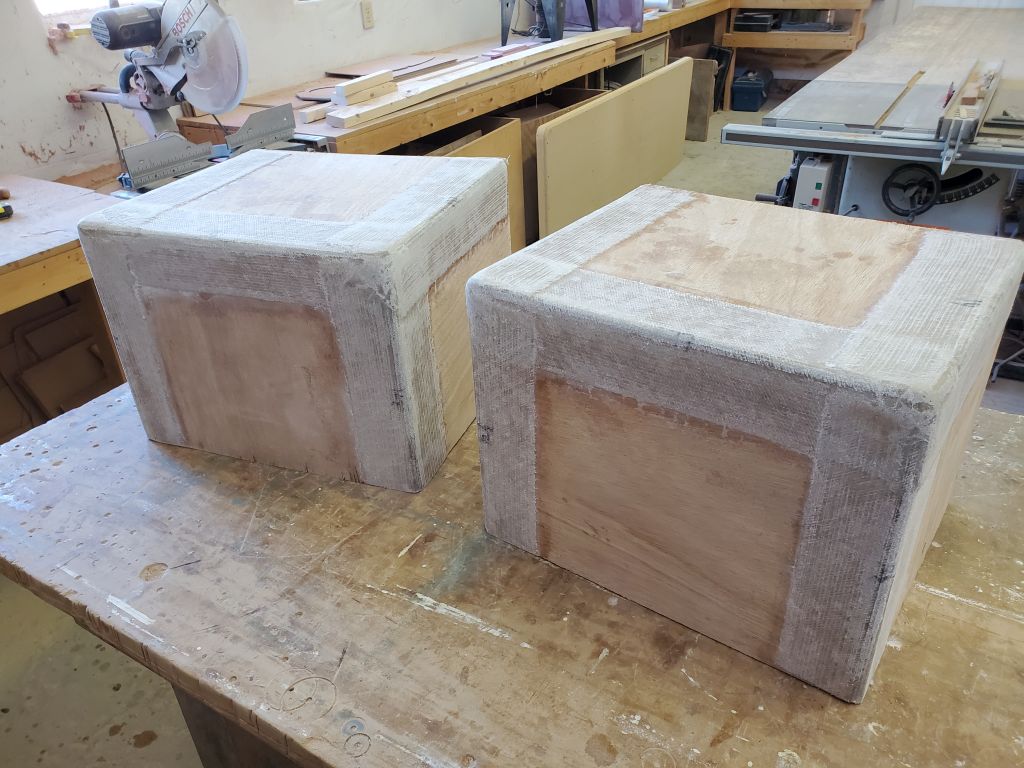
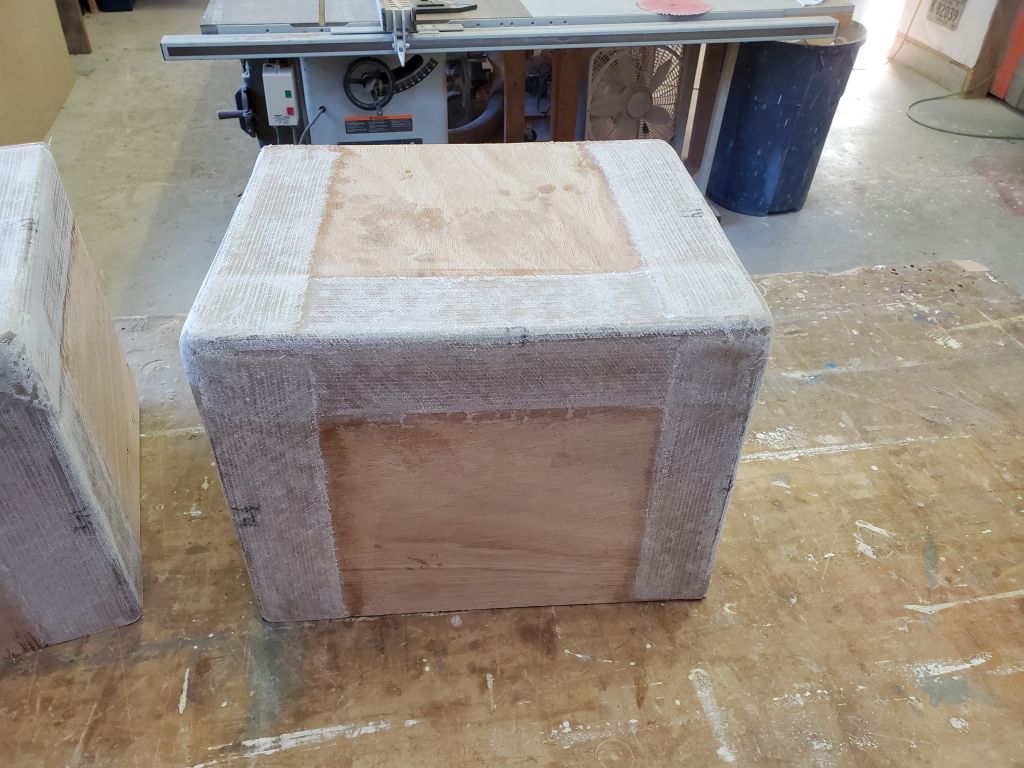
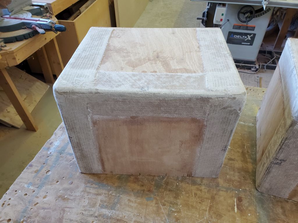
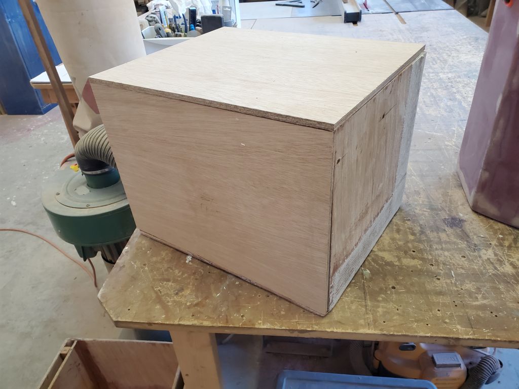
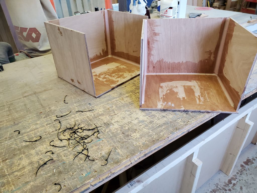
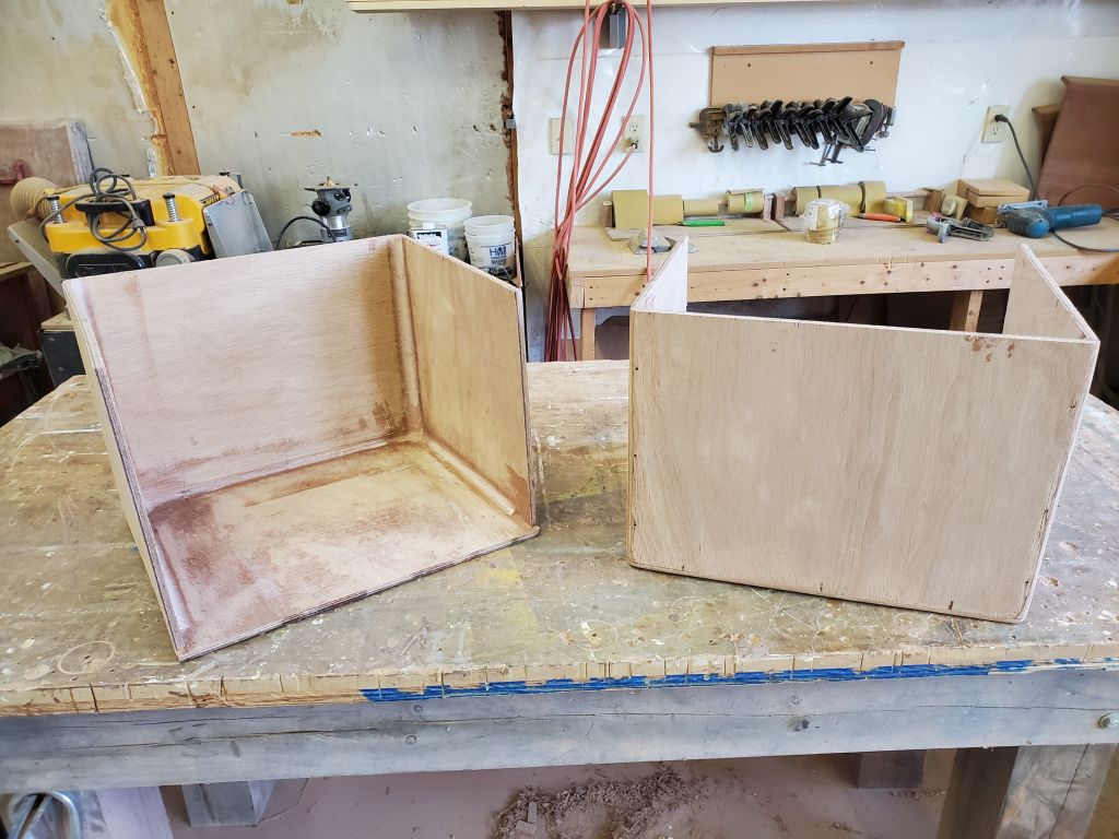
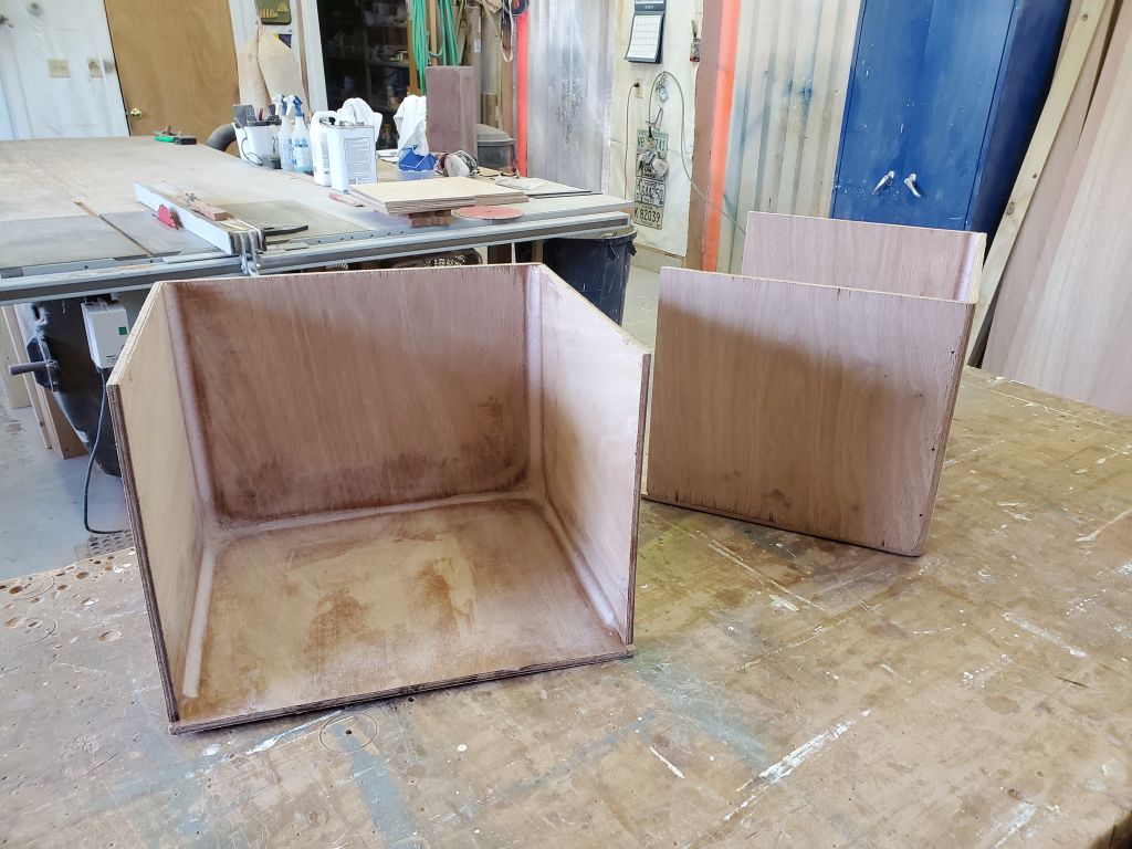
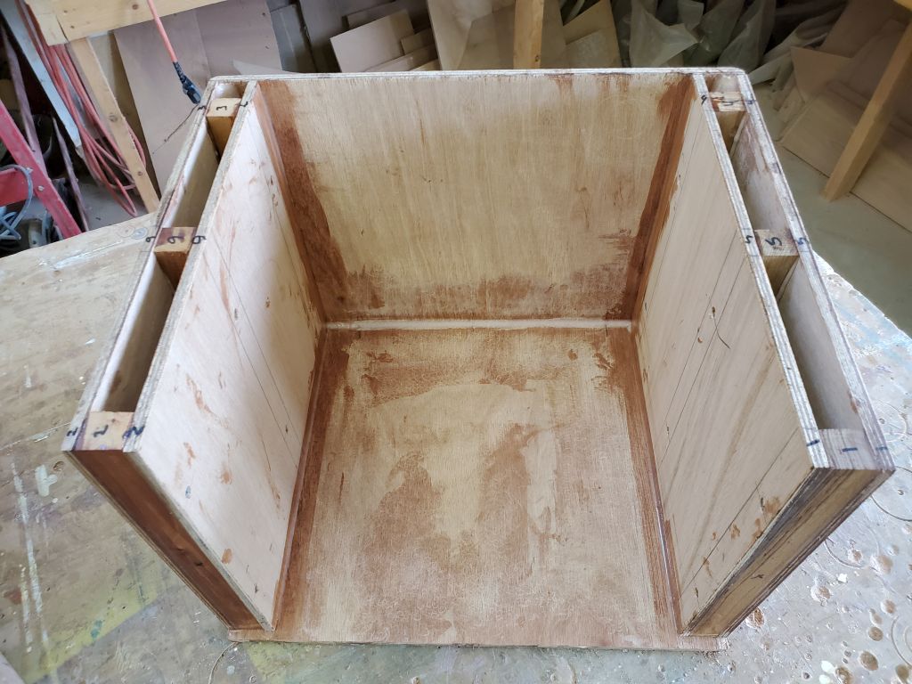
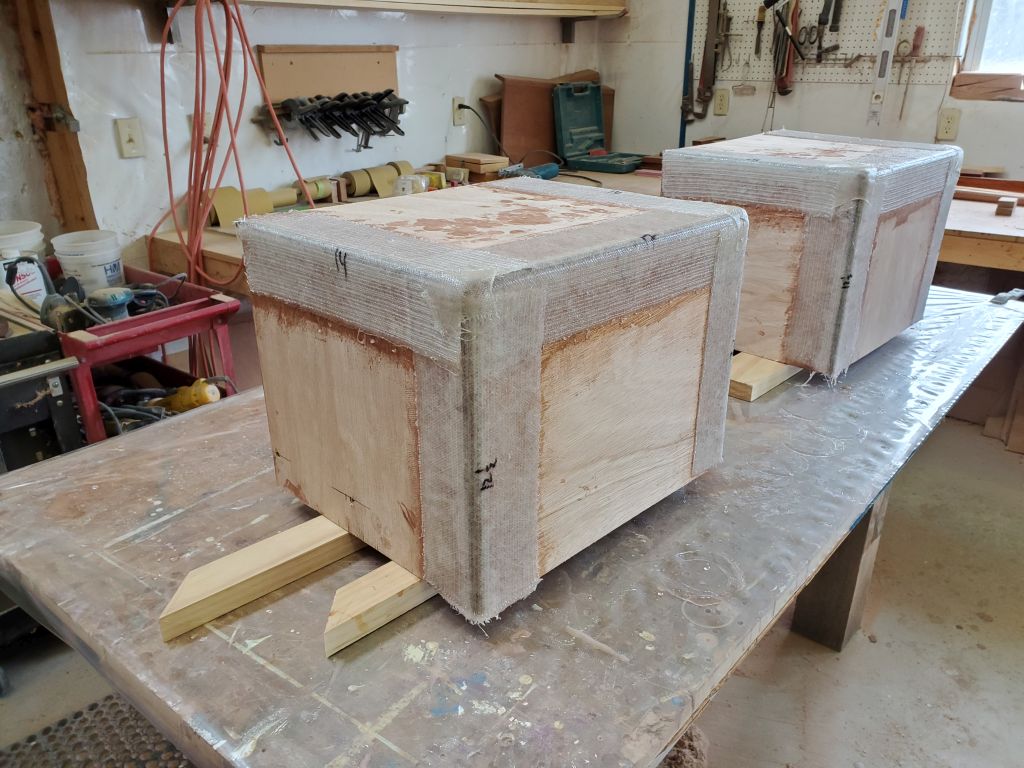
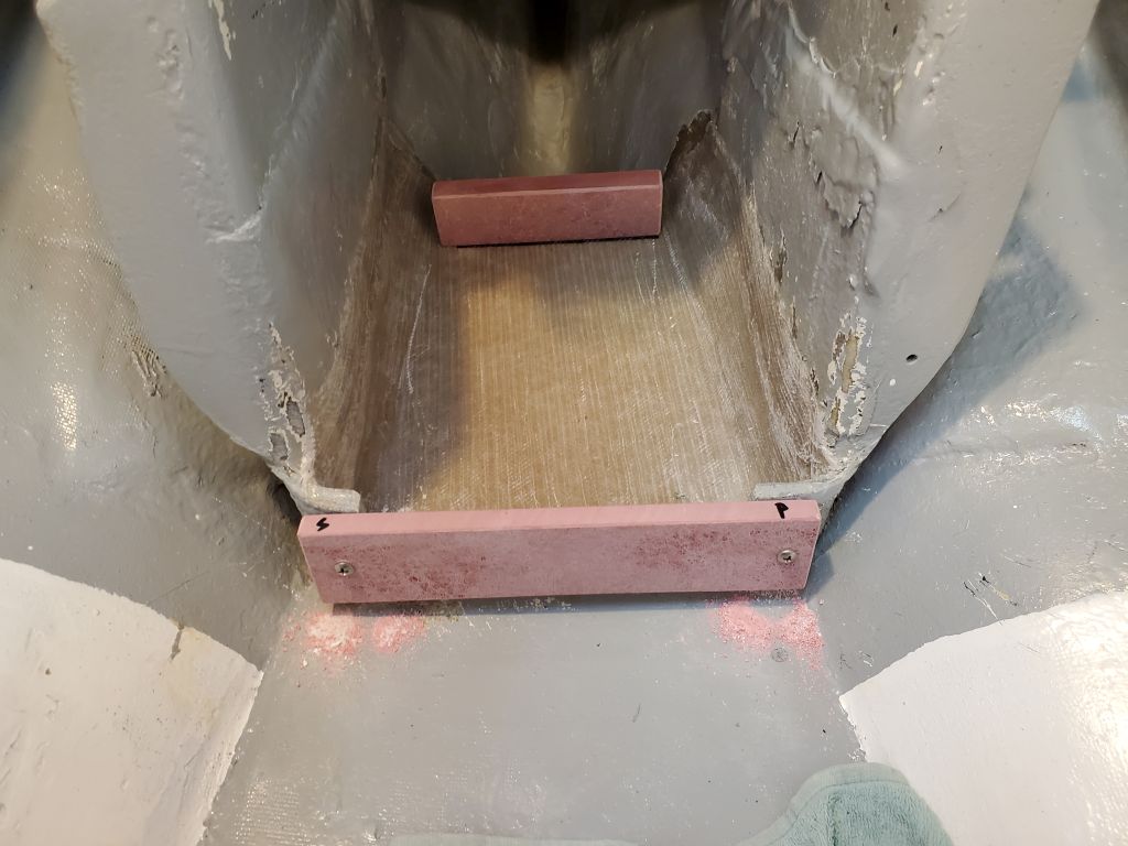
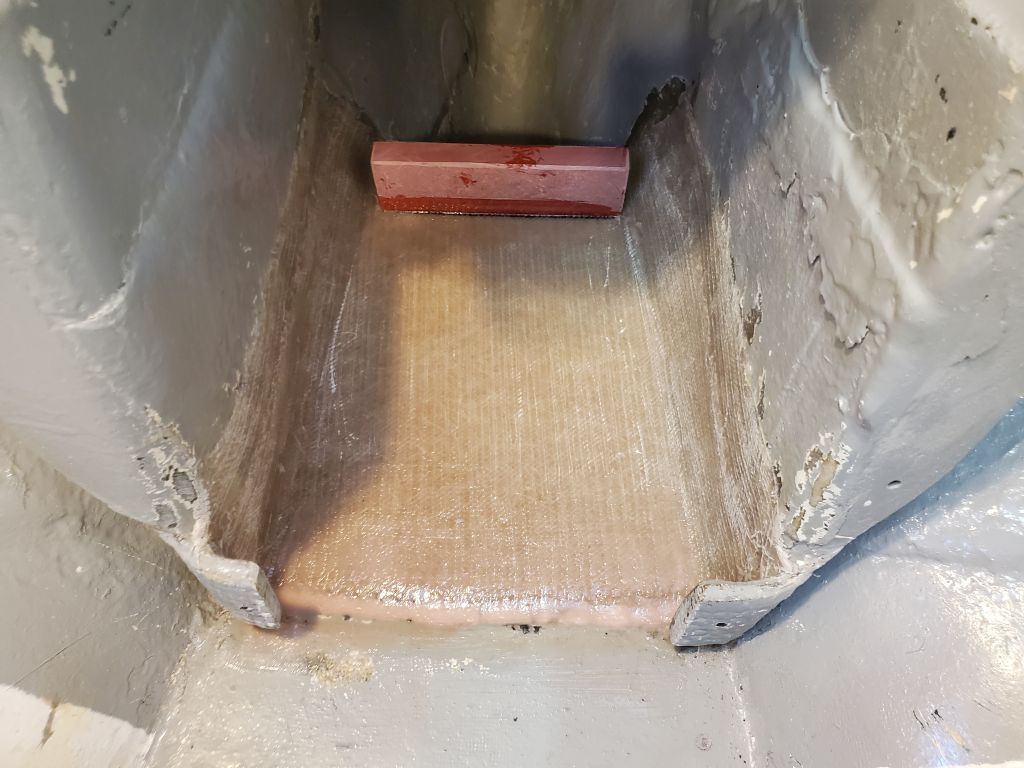
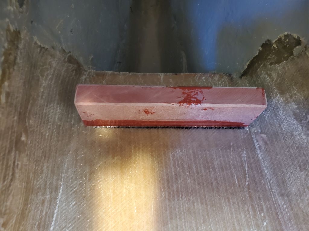
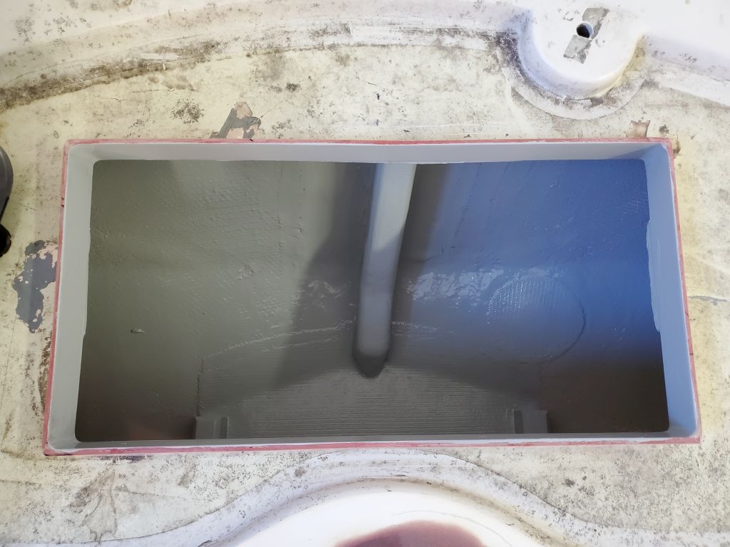
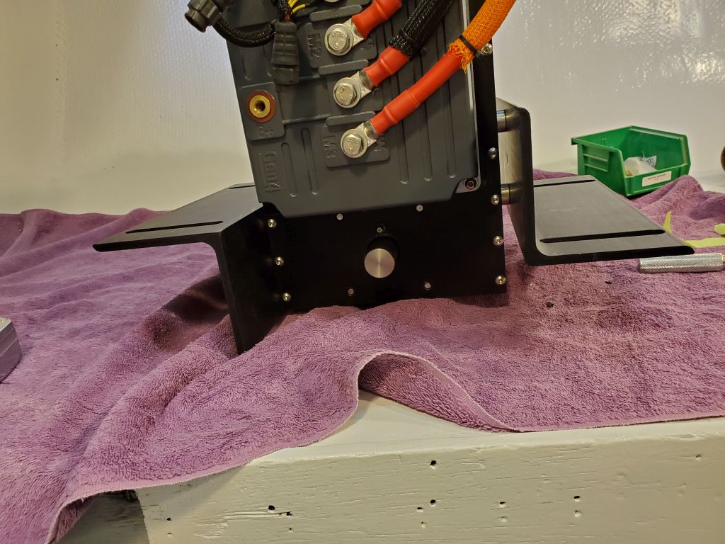
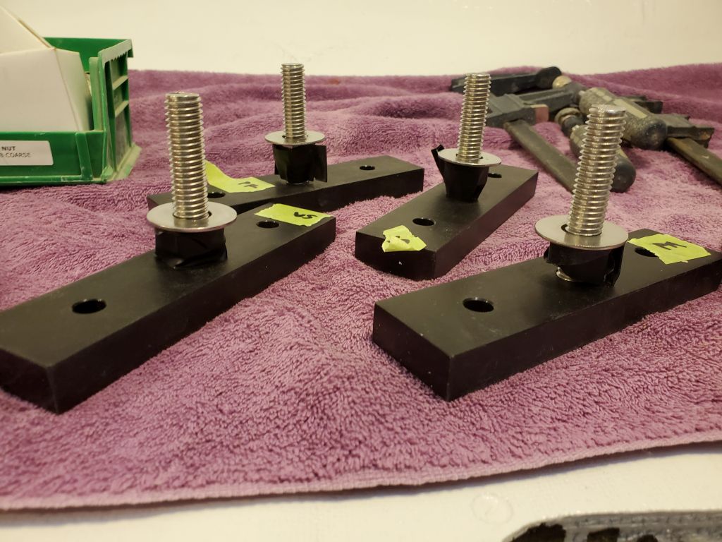
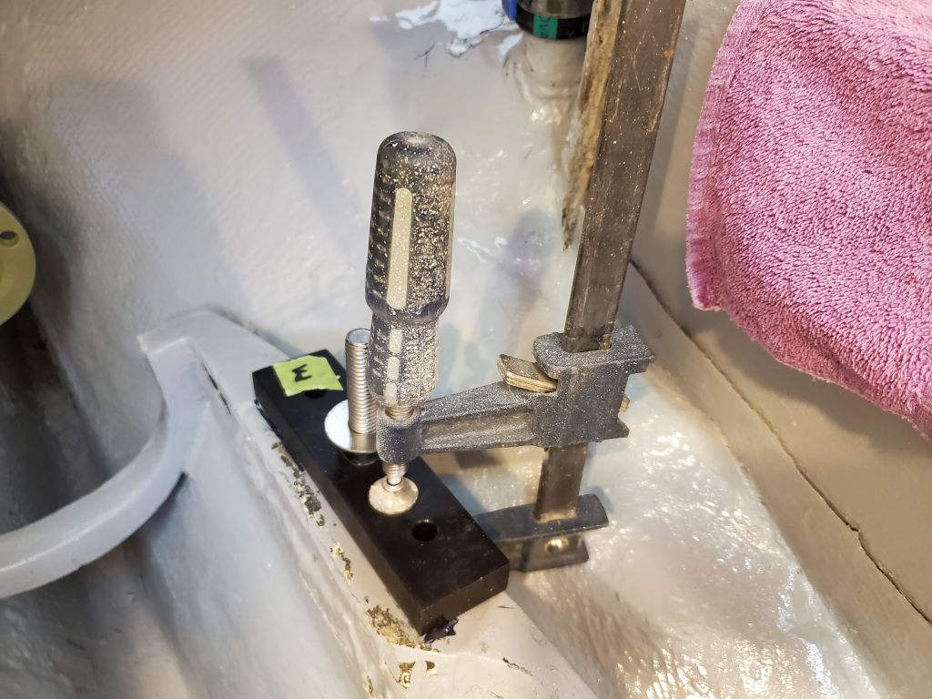
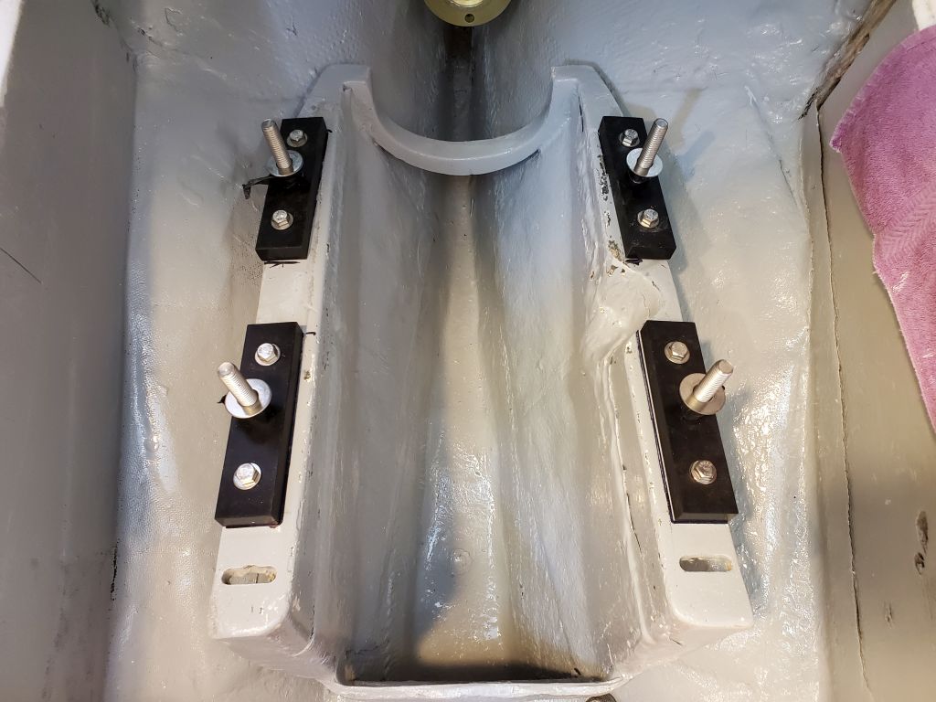
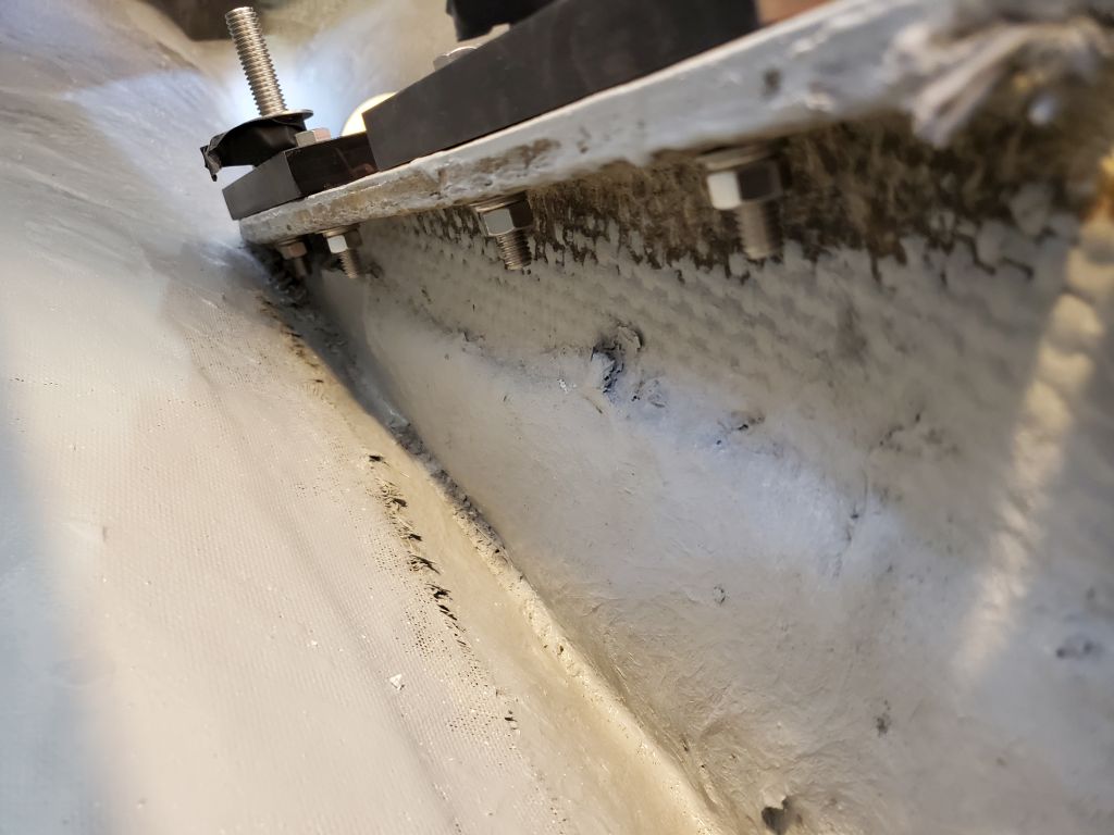
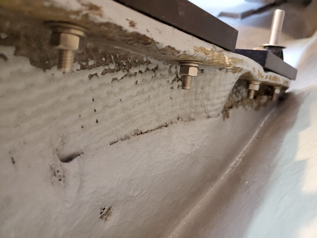
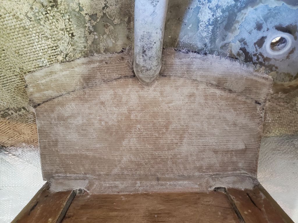
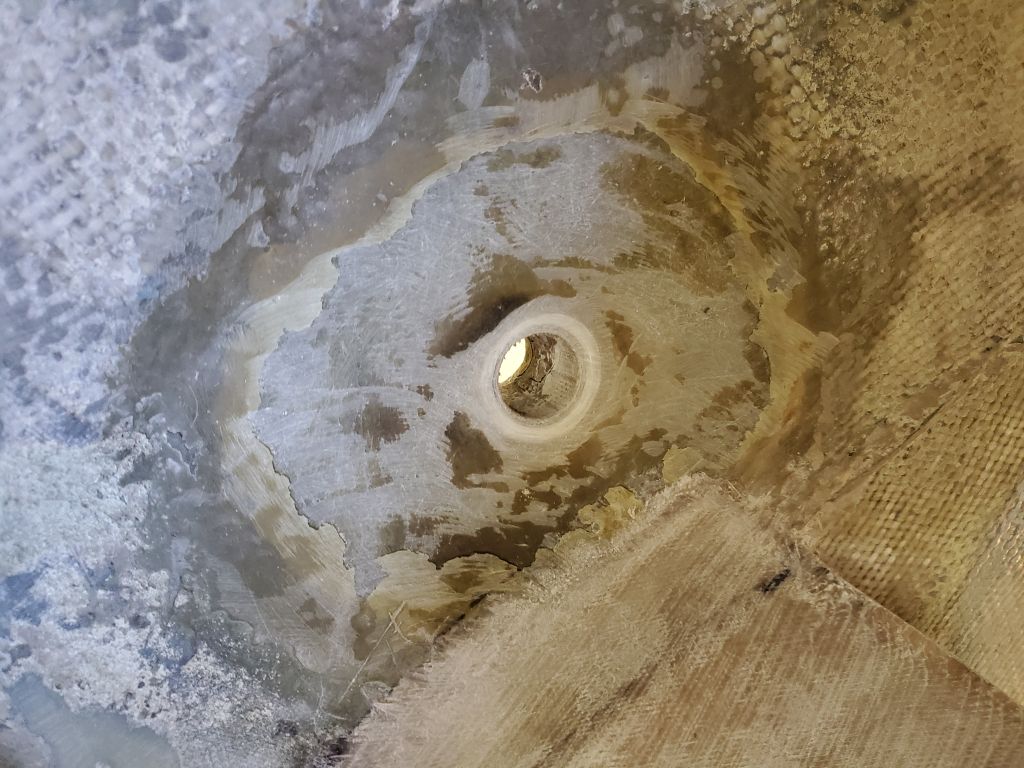
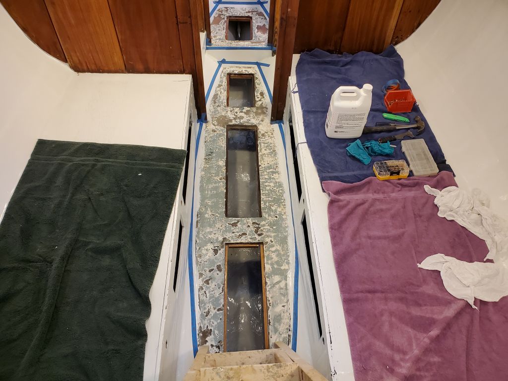
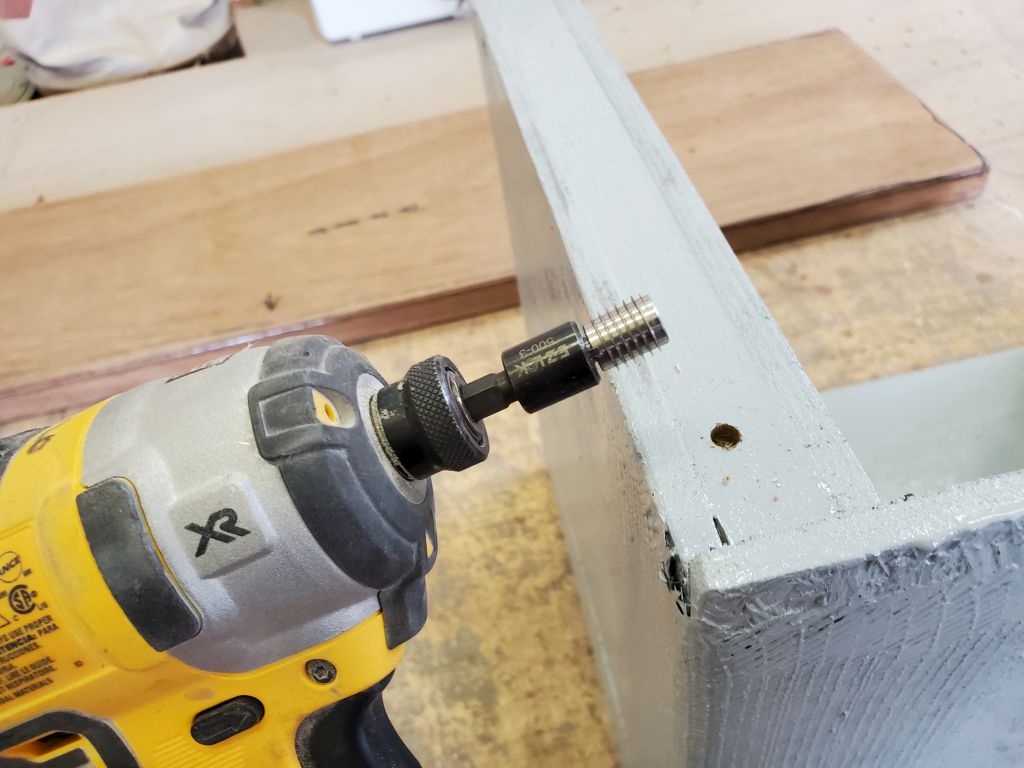
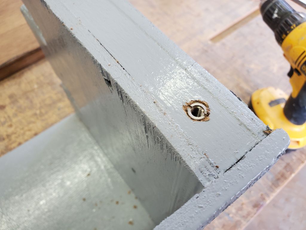
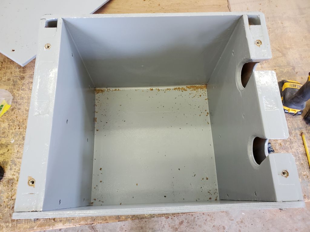
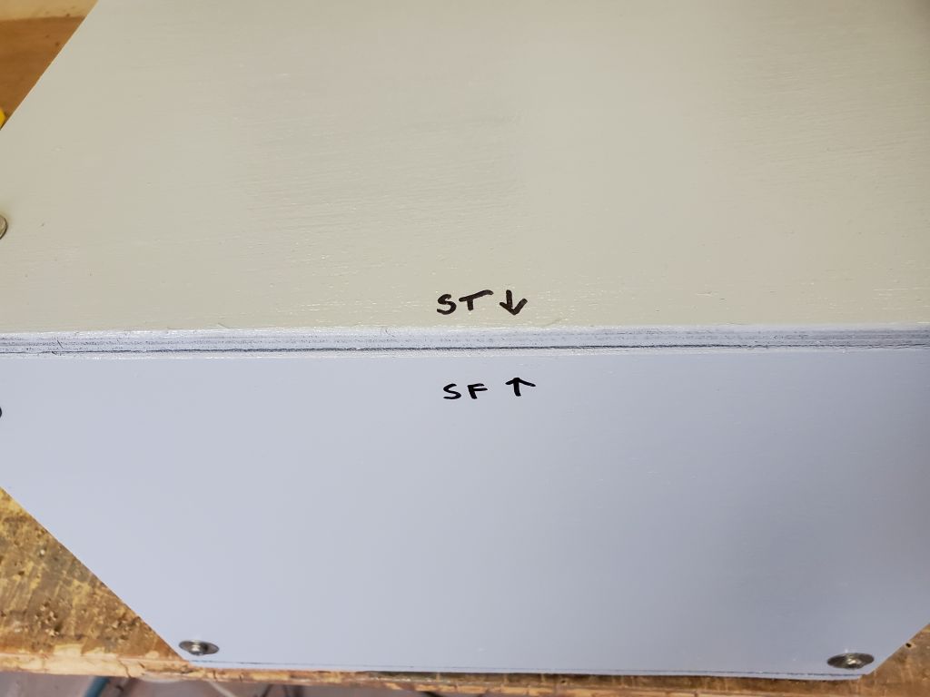
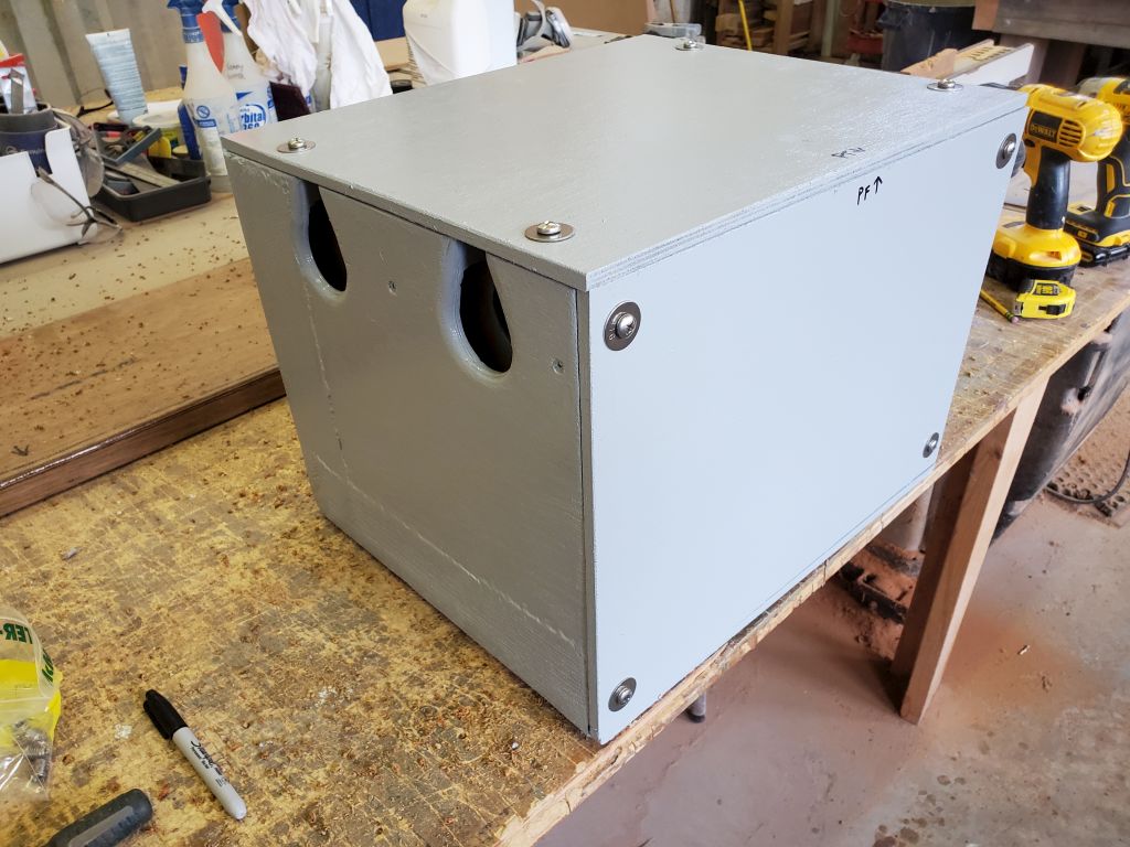
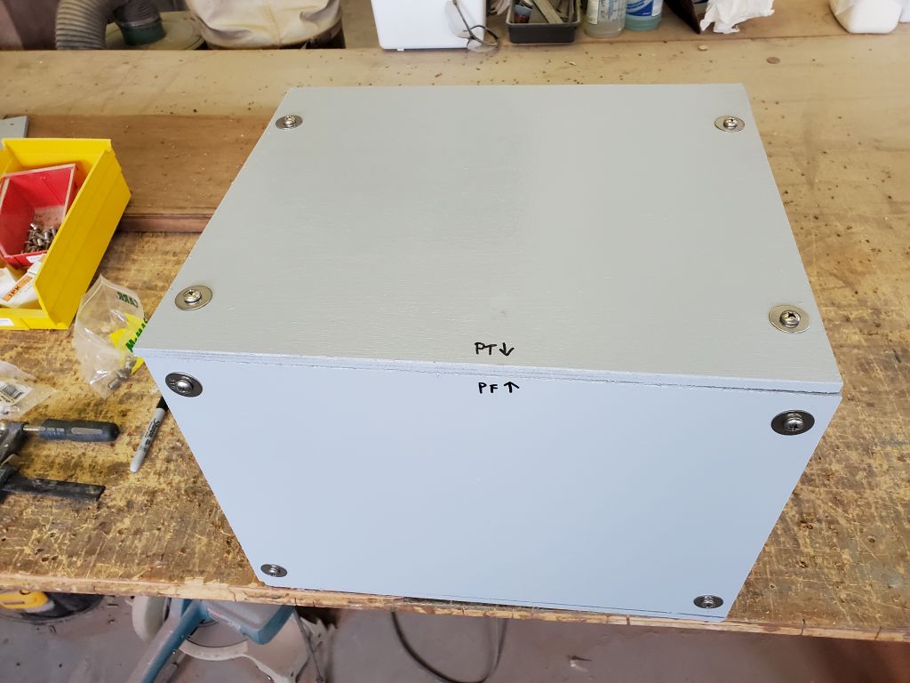
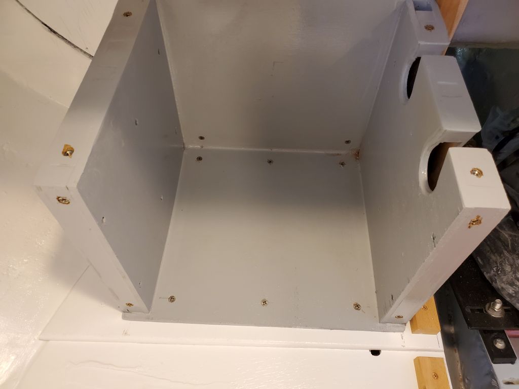
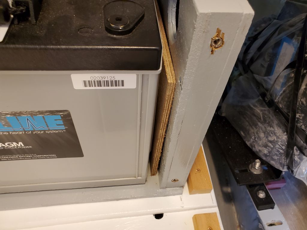
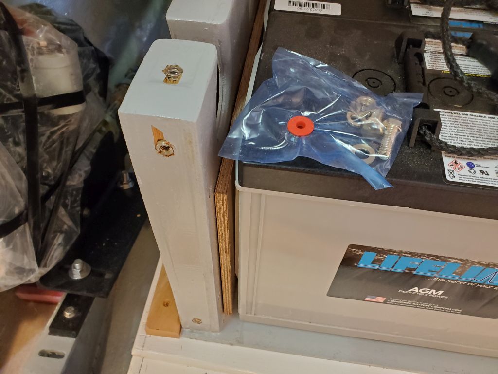
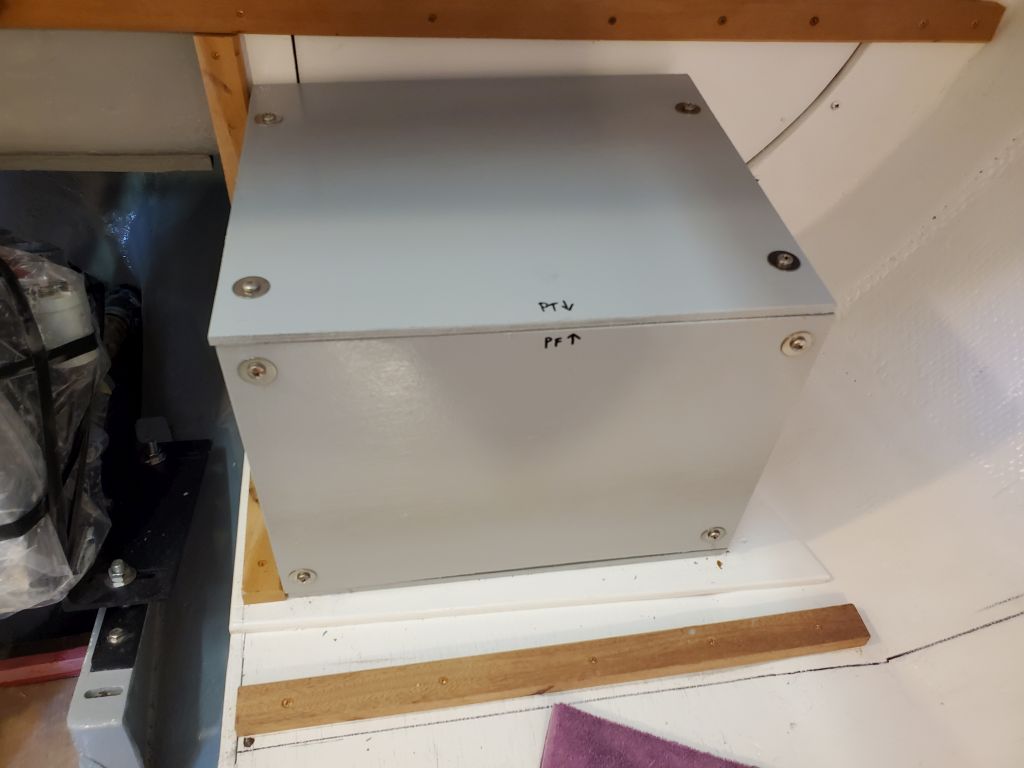
Now that the painting was complete, to finish up the battery boxes I installed a series of stainless steel threaded inserts to accept fasteners from the removable front and top panels.  These inserts, with sharp, aggressive outer threads, got installed in a predrilled hole in the wood with a special installation bit, and provided 1/4-20 machine screw threads on the inside.  I installed eight on each box:  four each for the top and front panels.

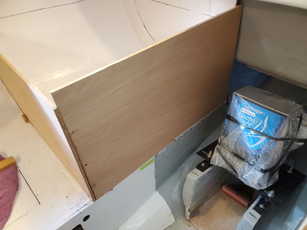
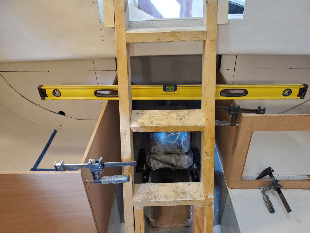
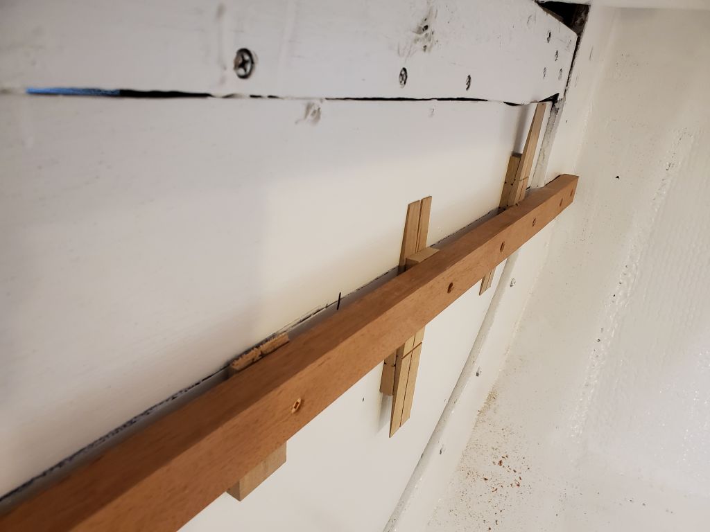
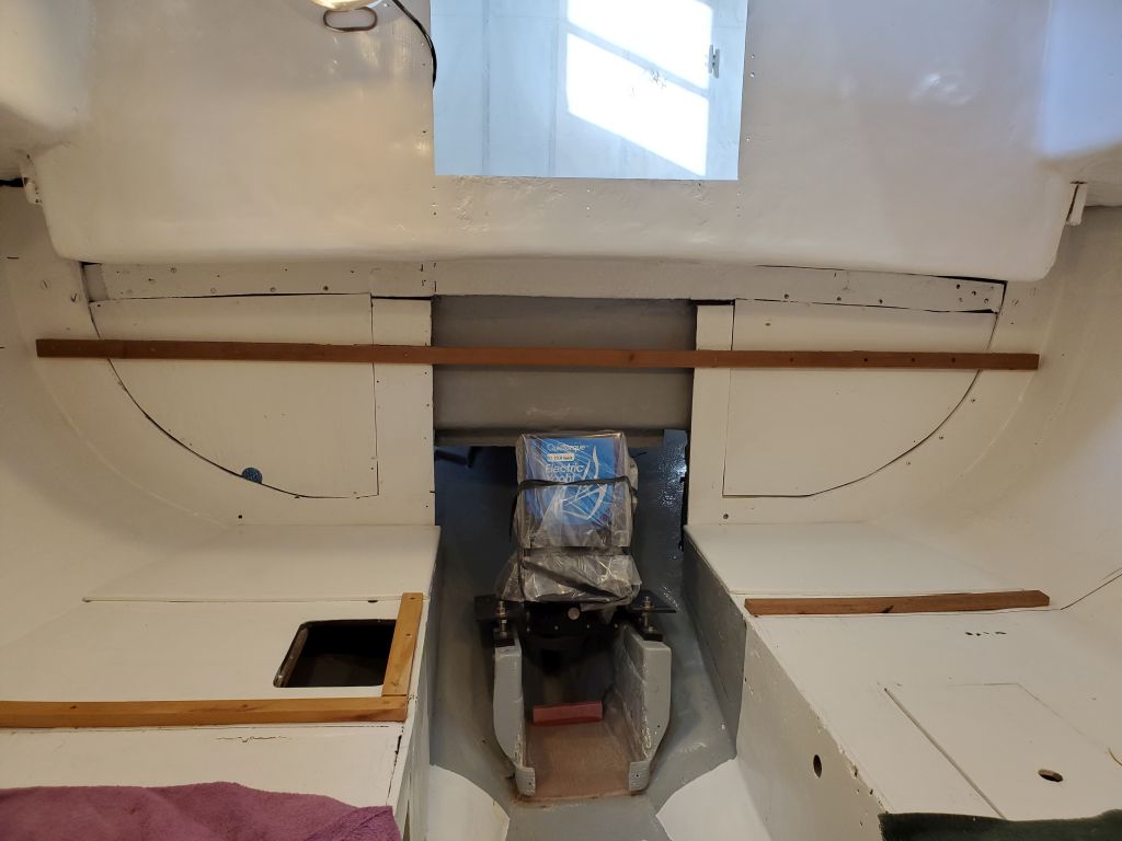
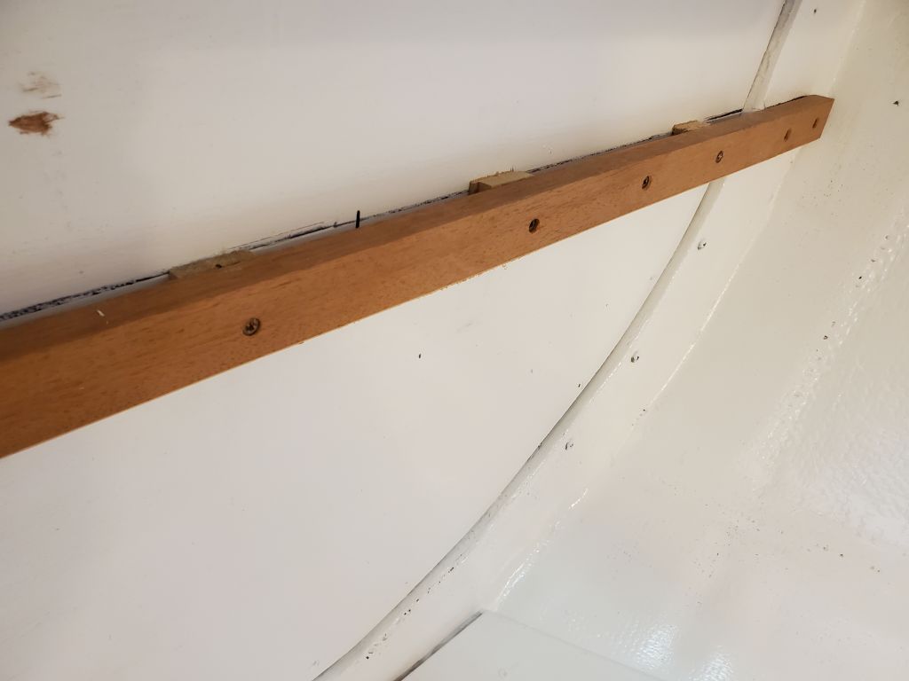
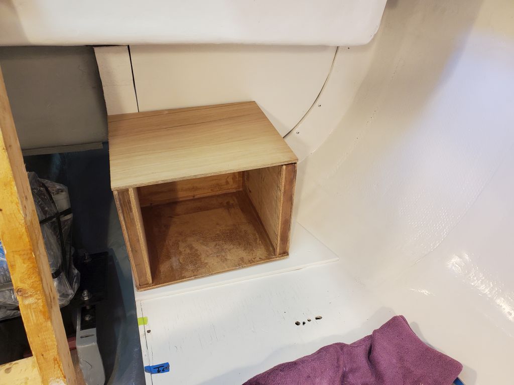
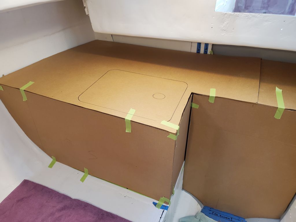
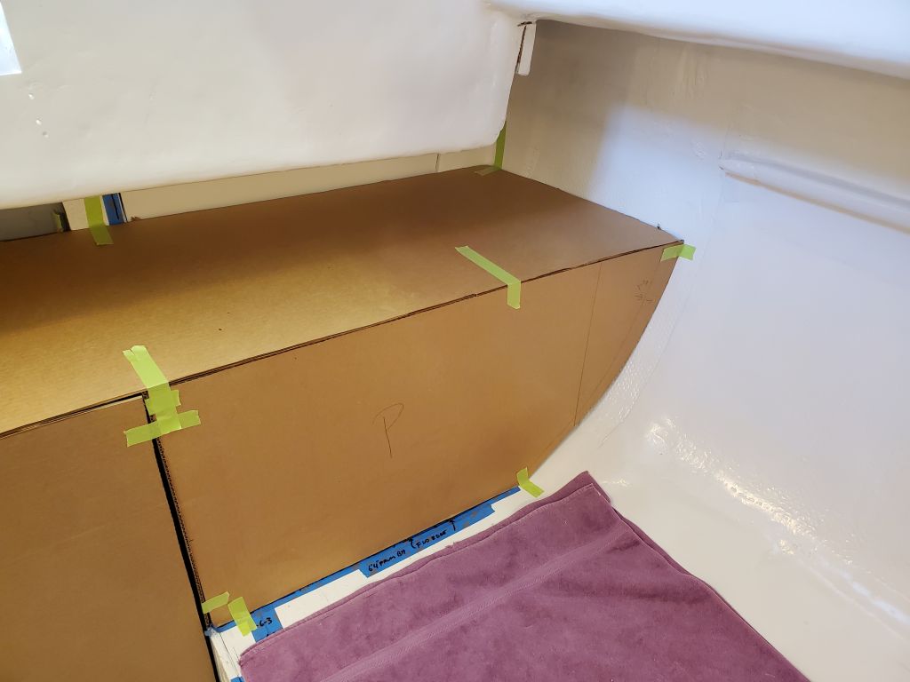
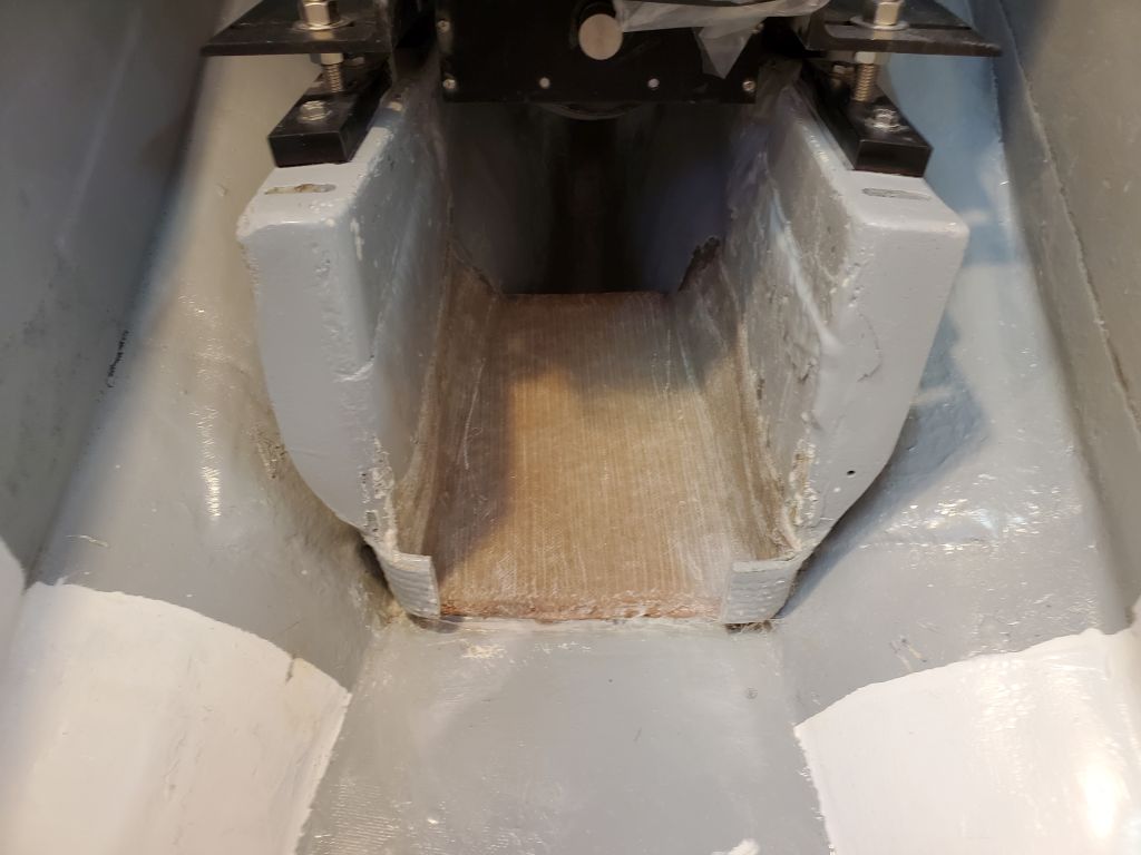
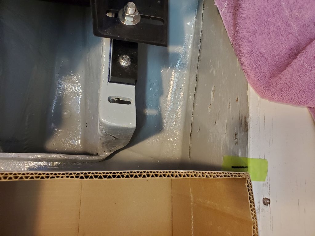
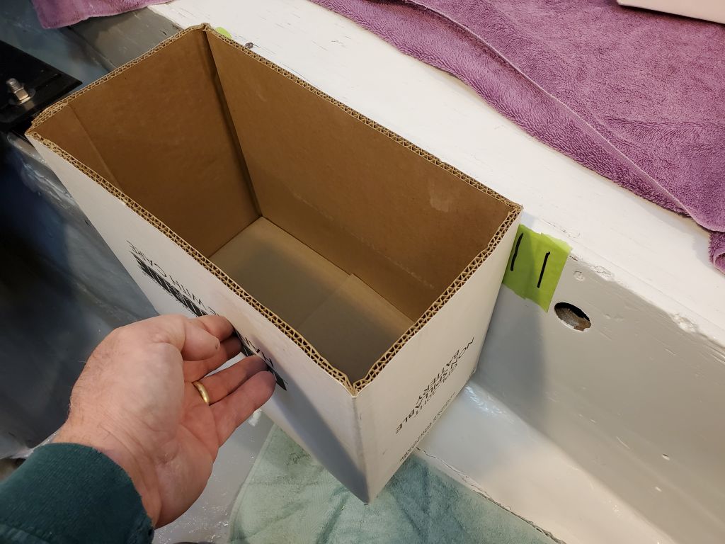
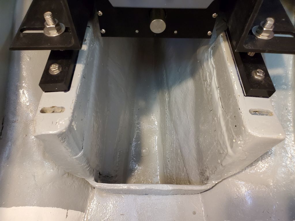
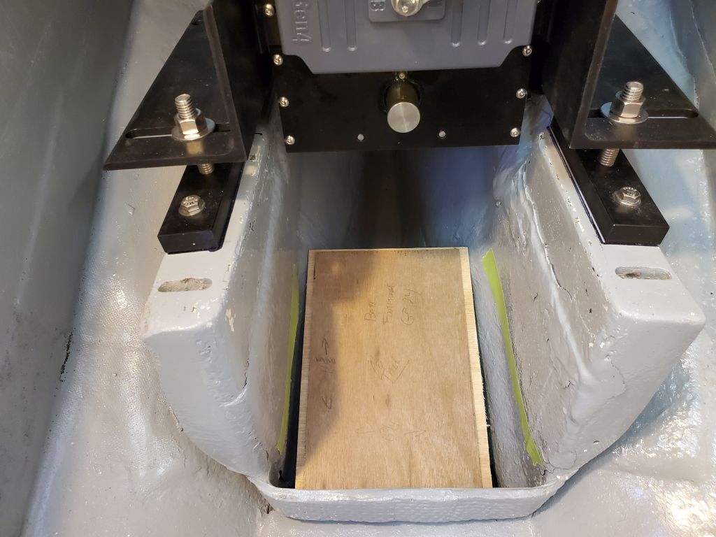
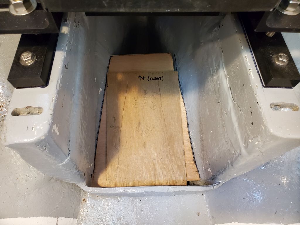
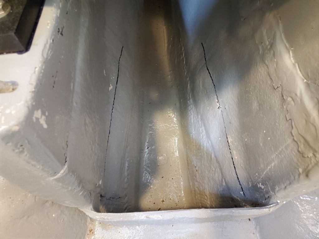
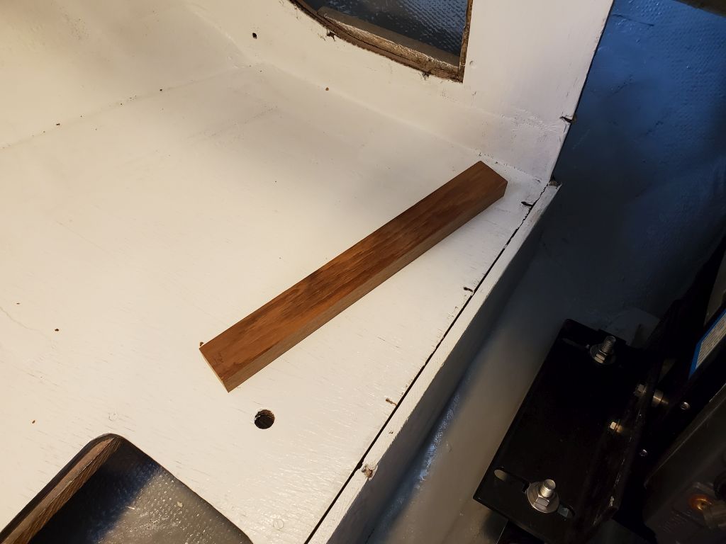
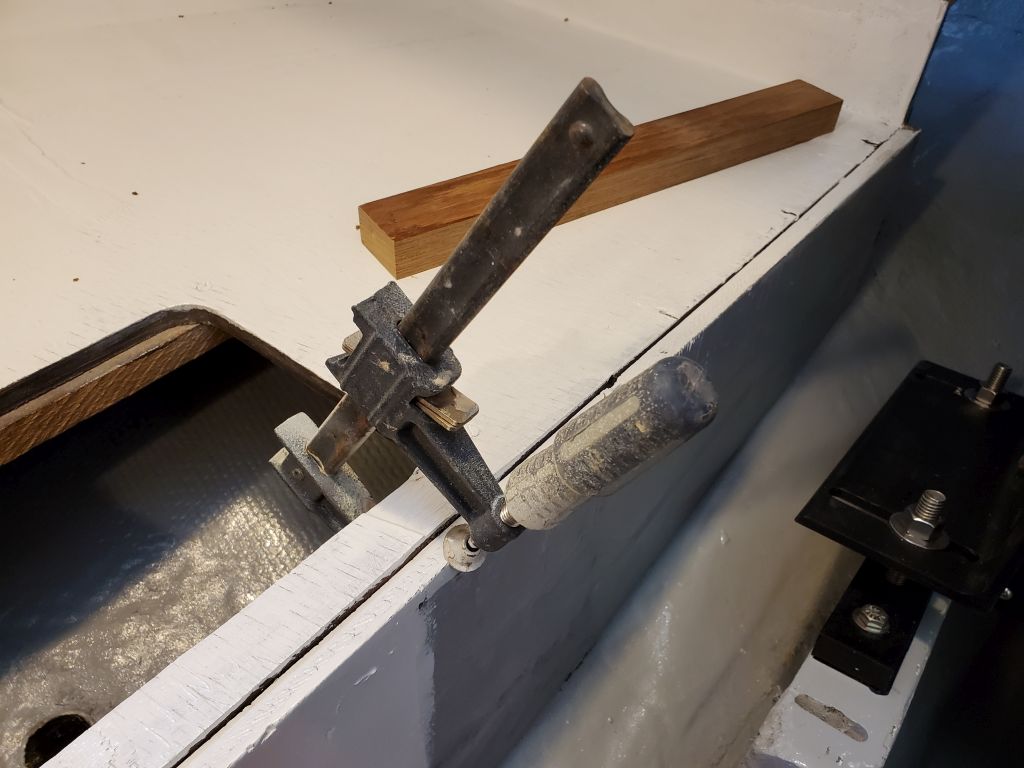
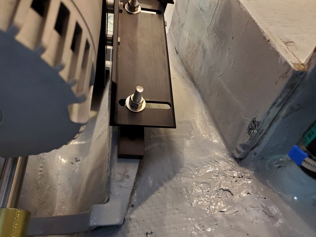
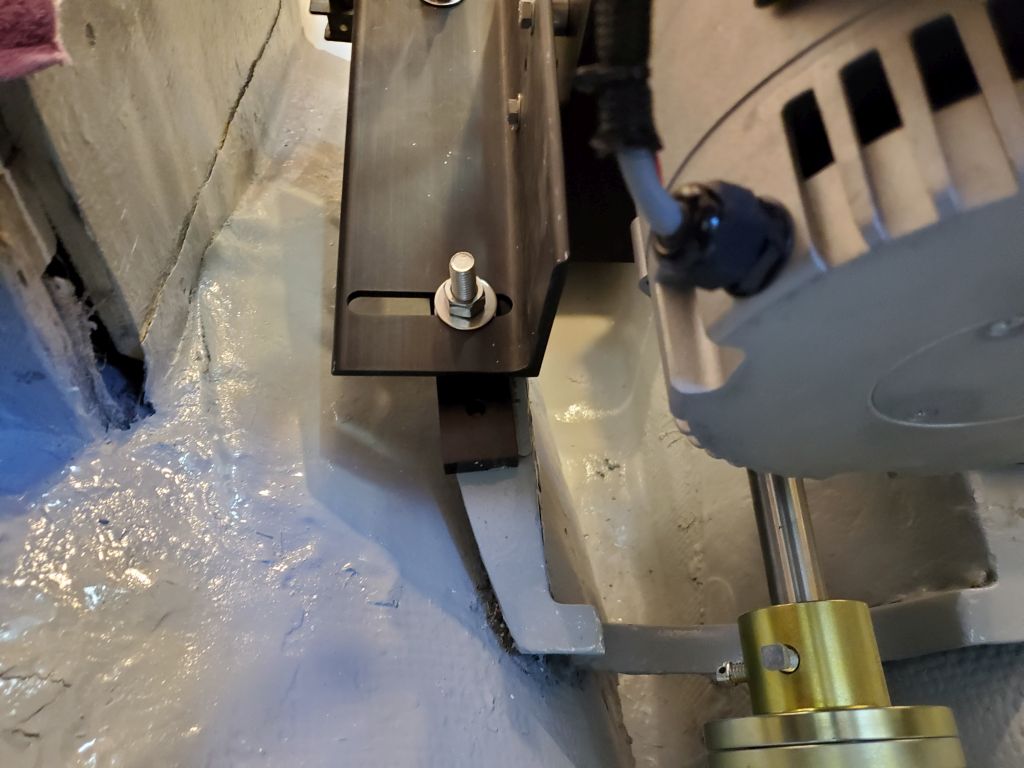
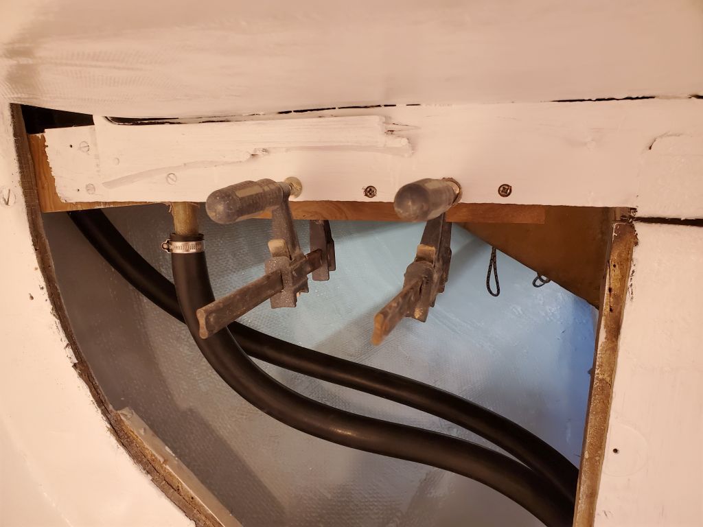
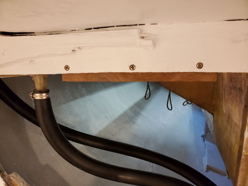
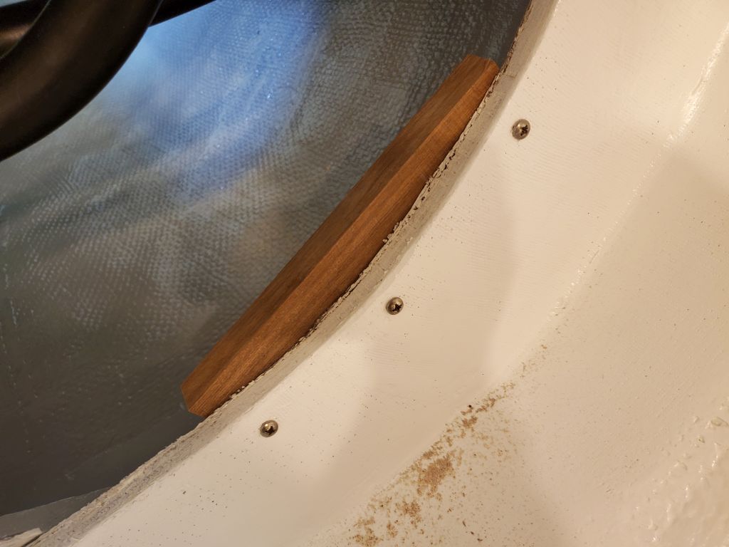
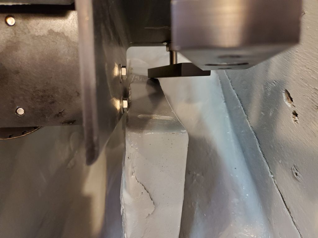
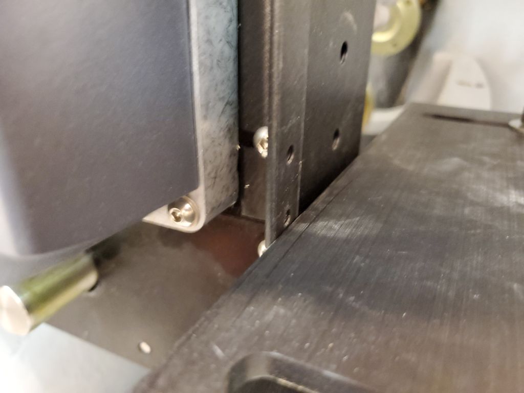
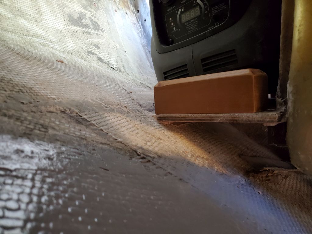
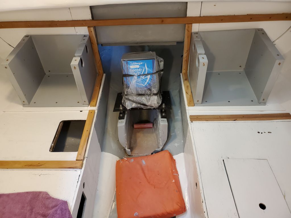
Test-fitting the boxes in the boat, I found immediately that my thought of using the boxes to support the longitudinal engine room panels was not going to work, as the various undulations of the original boat structure meant that the boxes did not line up perfectly with the plane of the panels.  So I installed more hardwood cleats to line the engine space, which would ultimately support the panels.

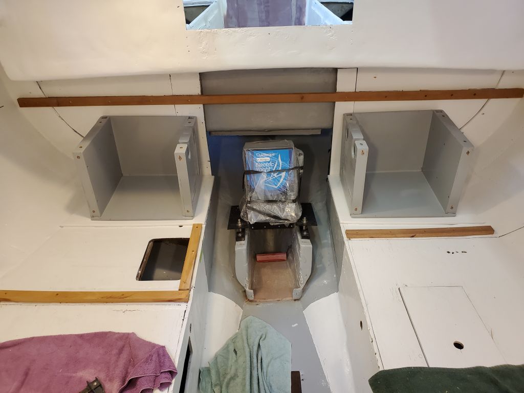
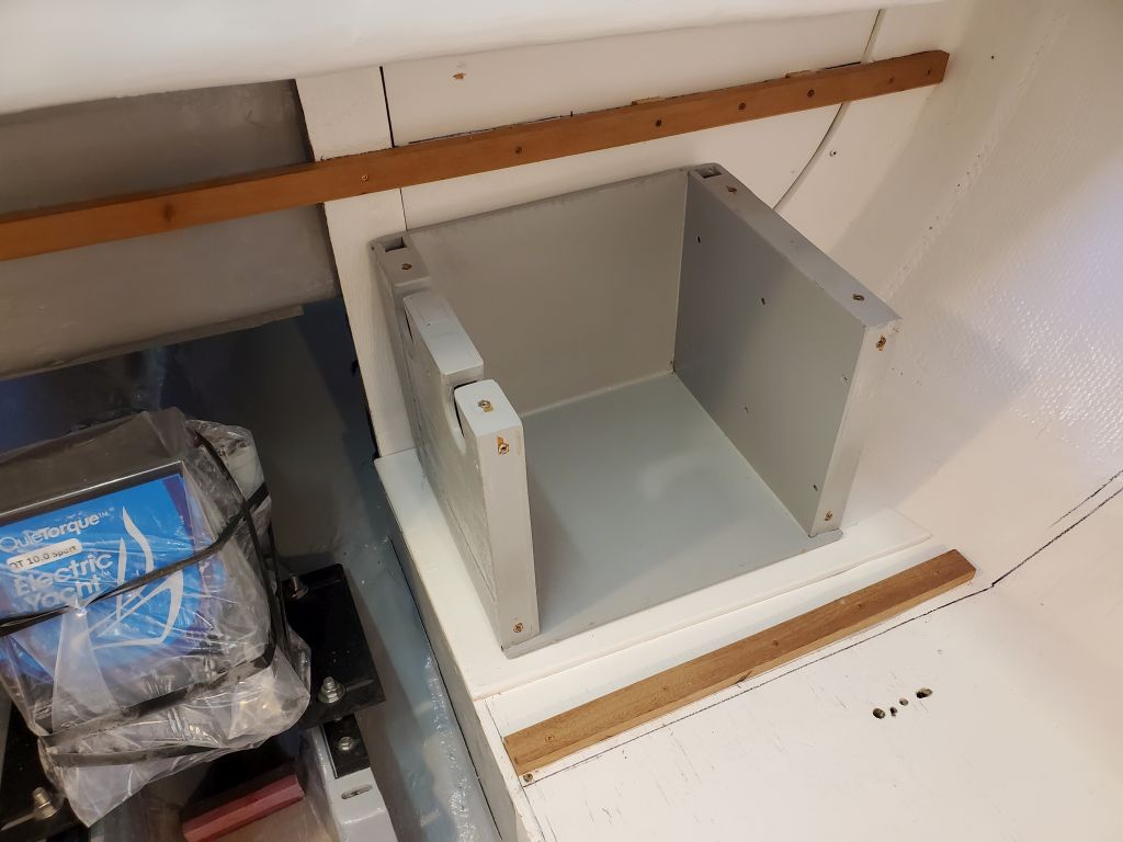
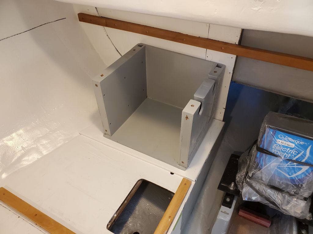
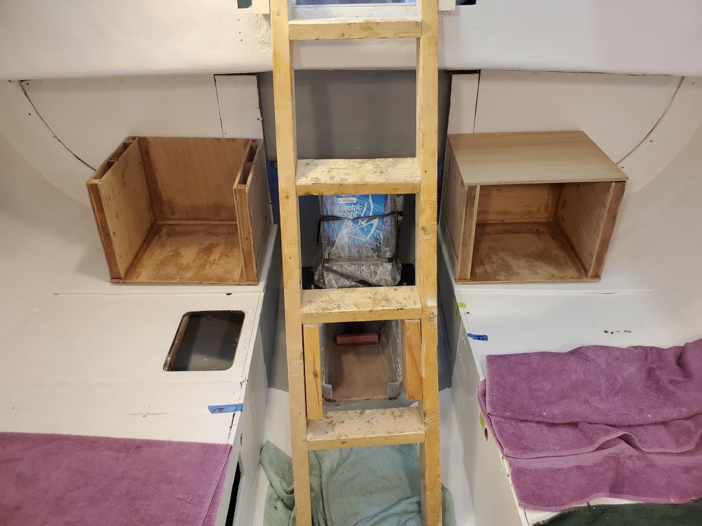
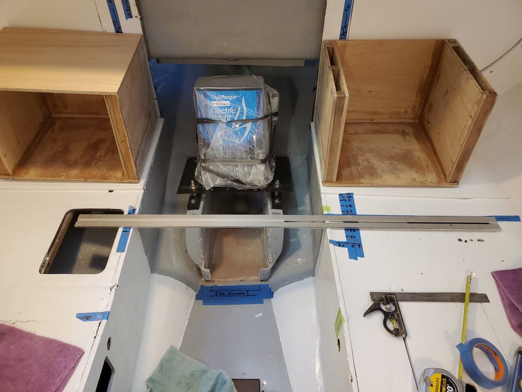
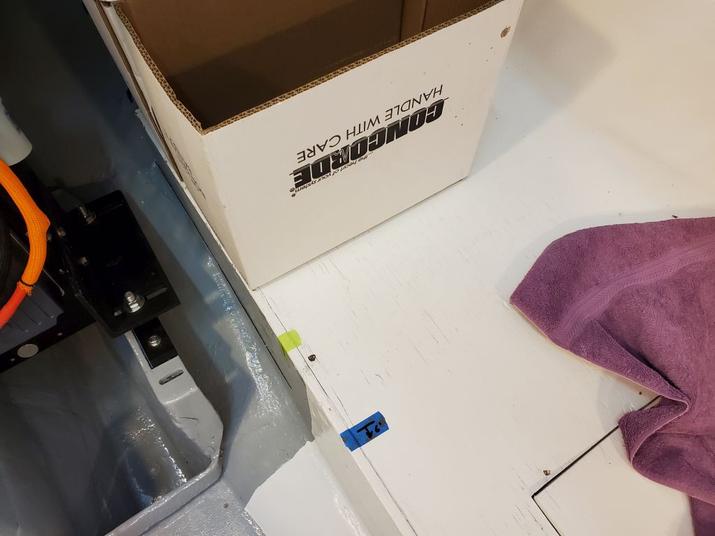
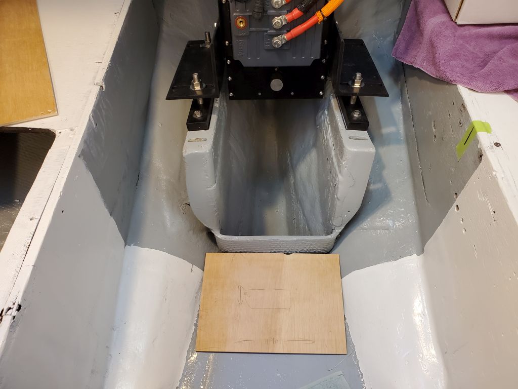
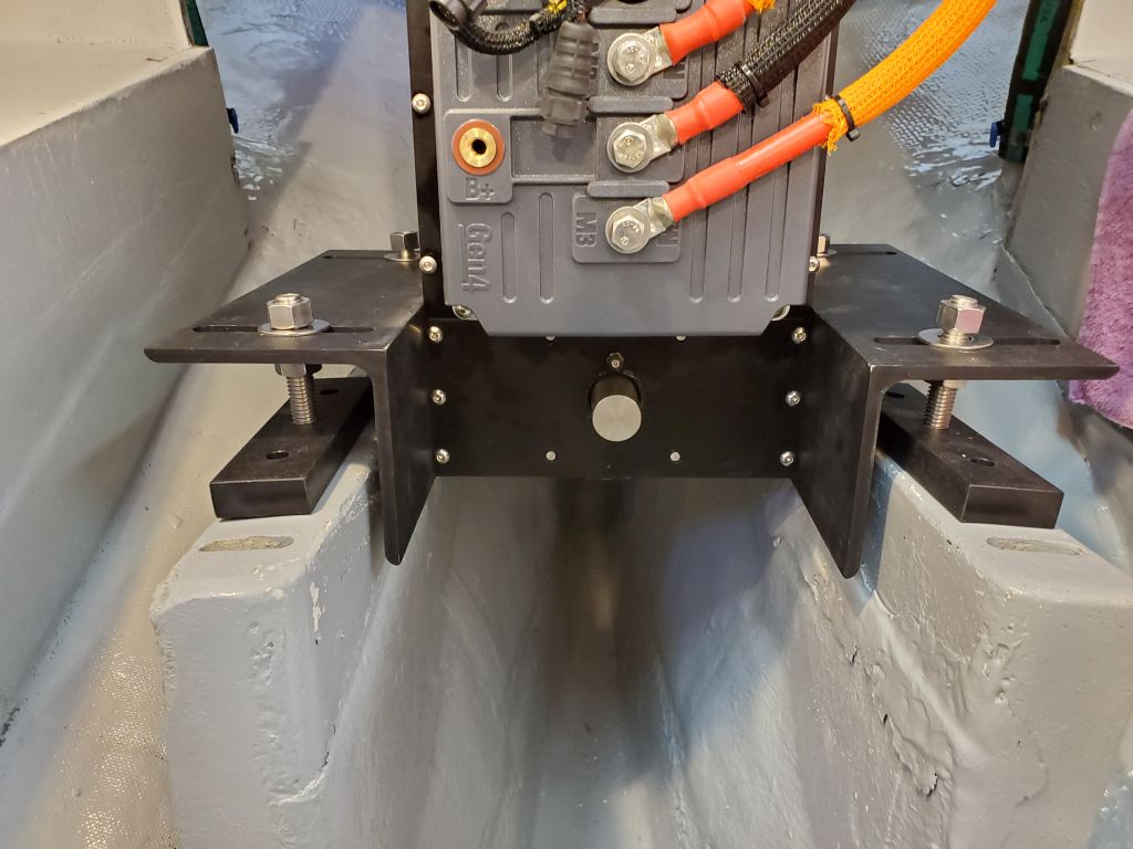
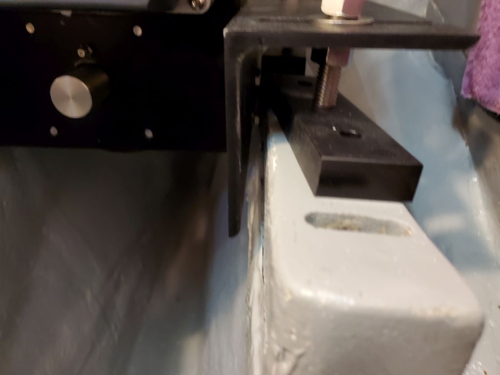
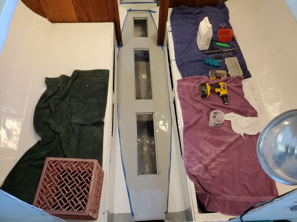
I permanently installed the battery boxes with eight screws per side:  Six through the box bottoms into the reinforced berths beneath; and two longer ones in the backs and into the fiberglassed portion of the aft bulkhead.

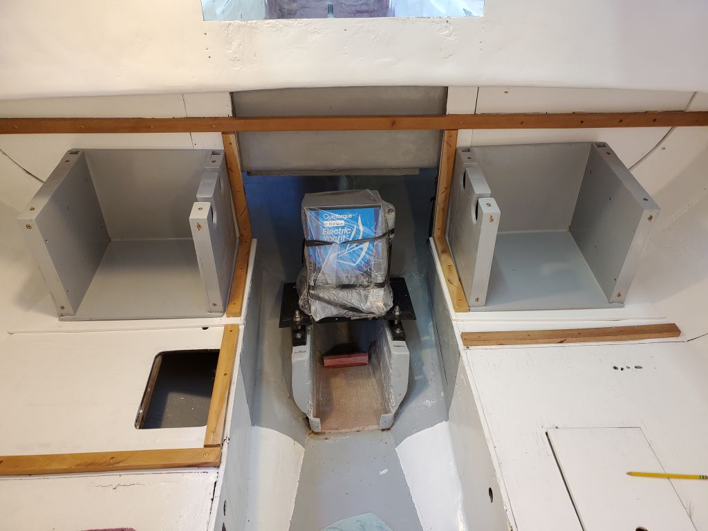
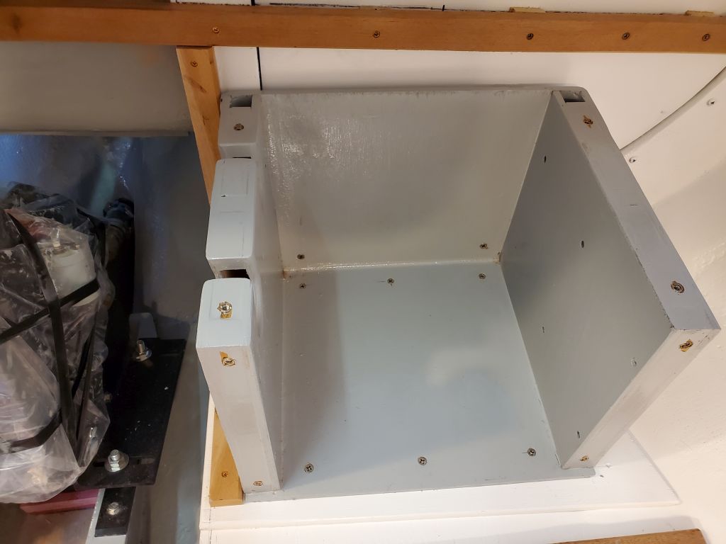
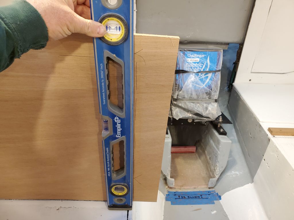
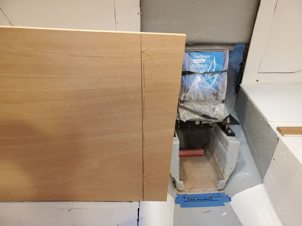
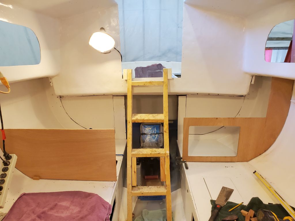
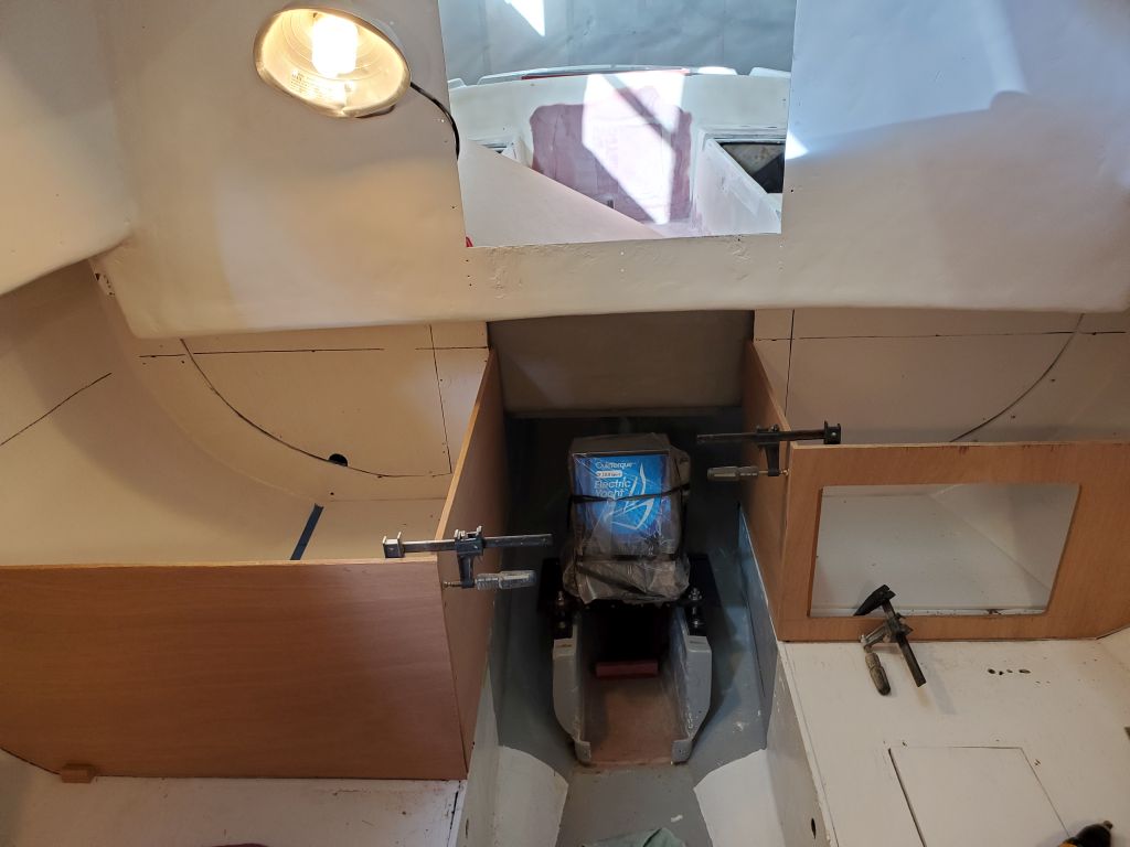
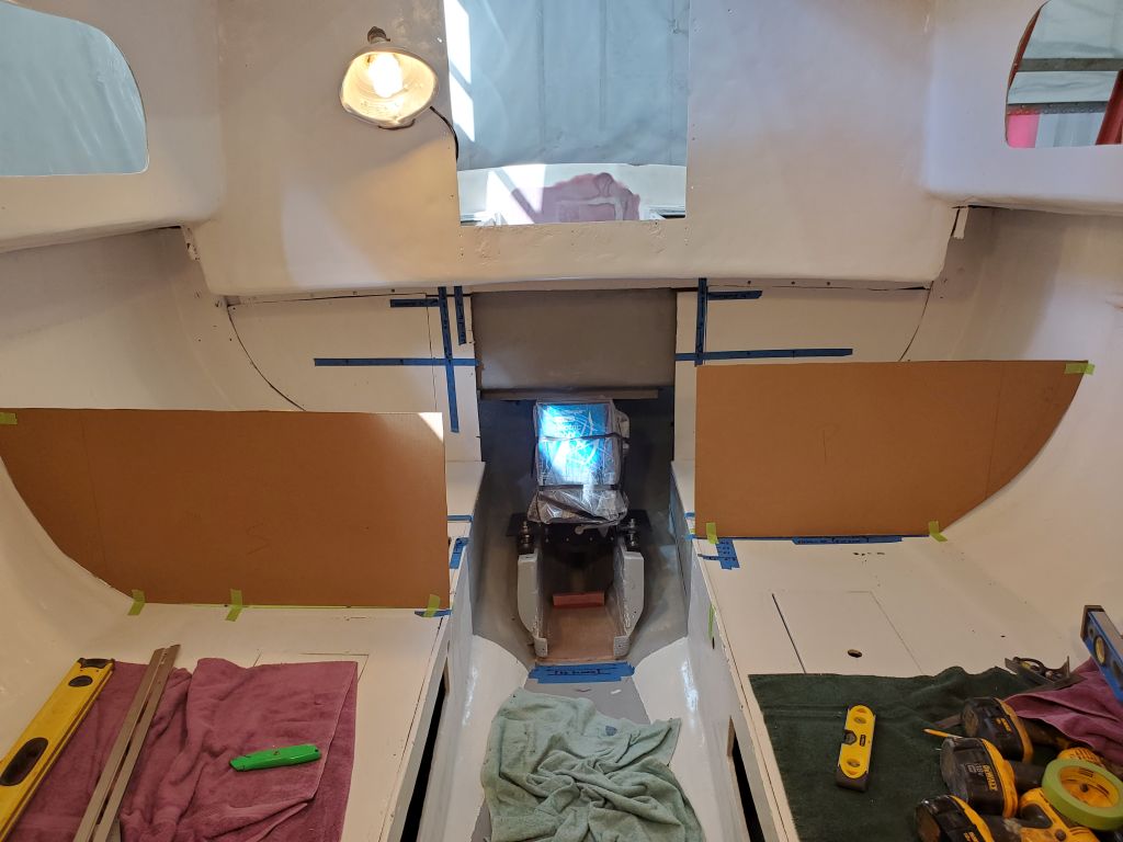
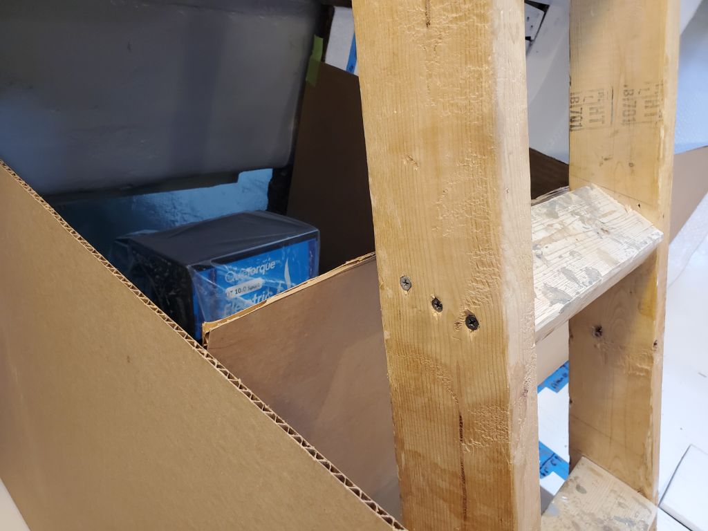
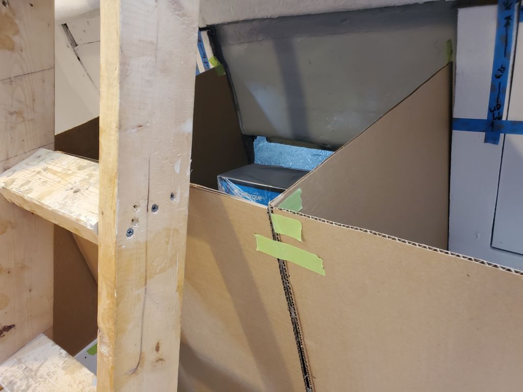
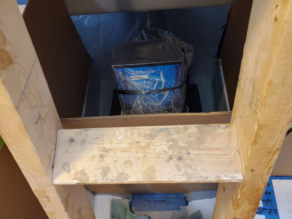
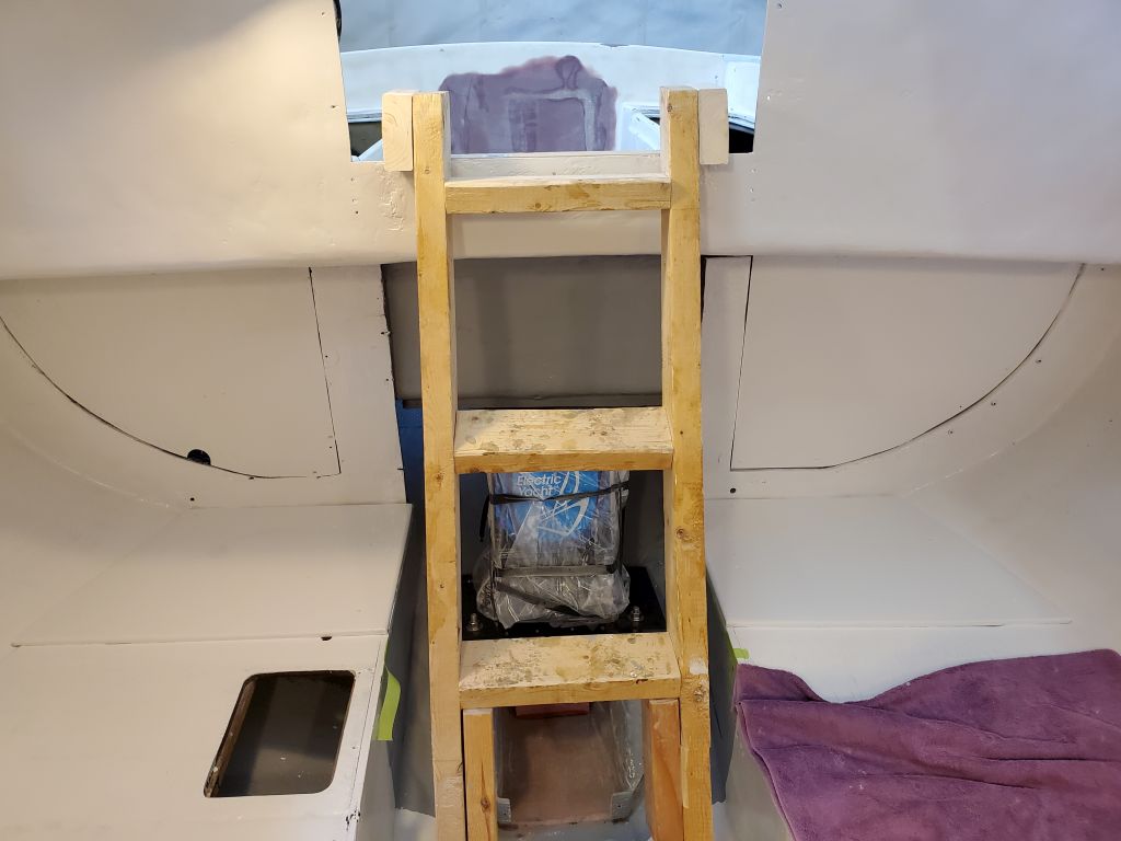
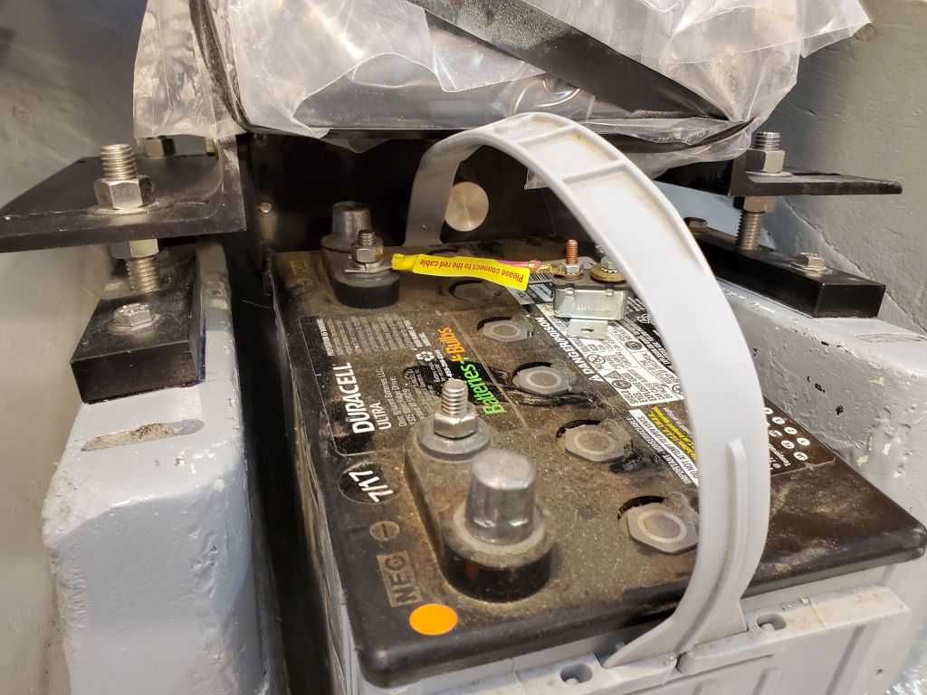
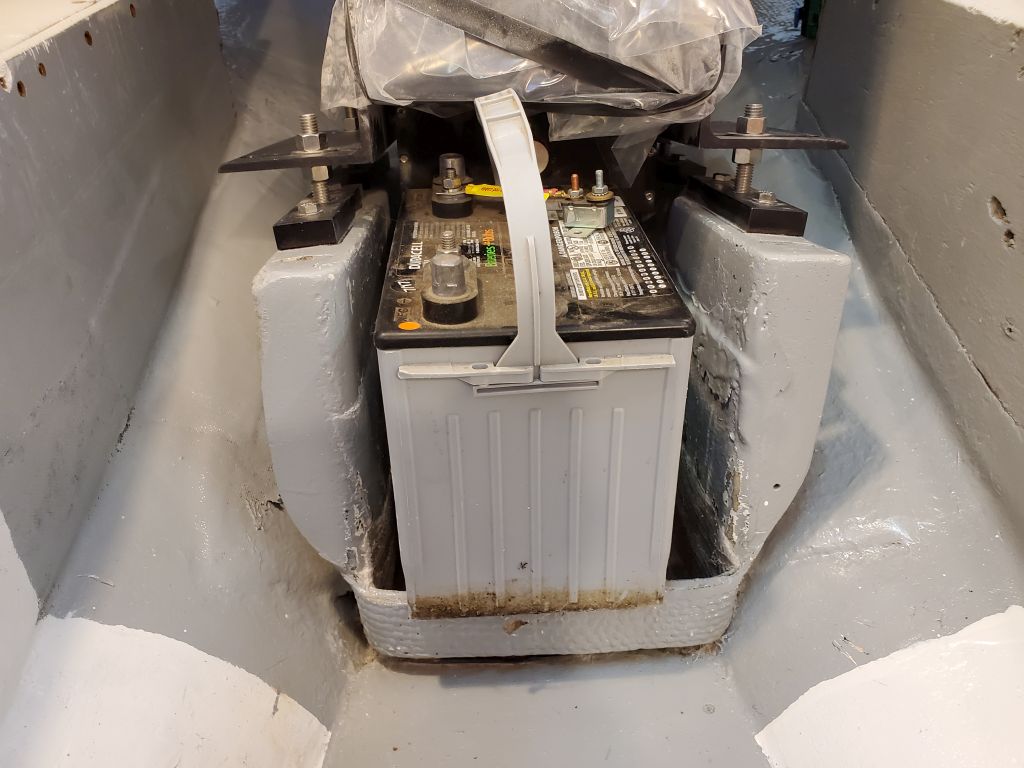
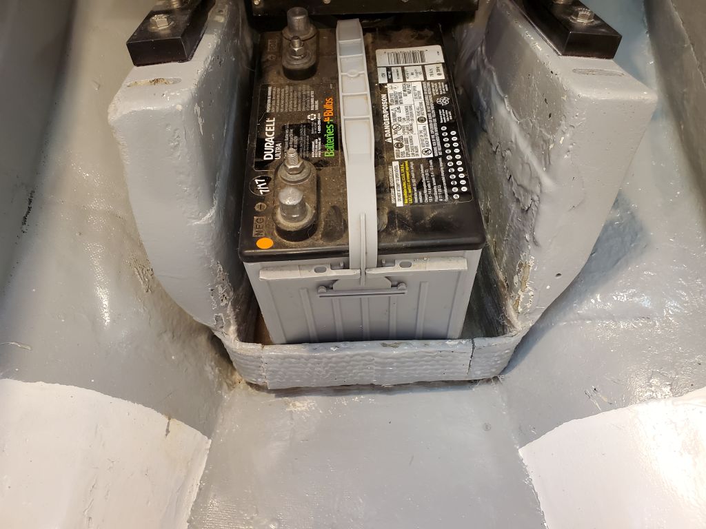
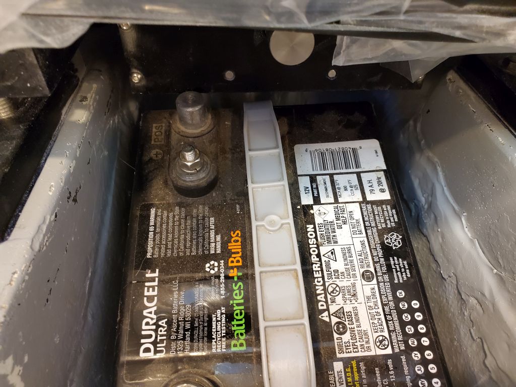
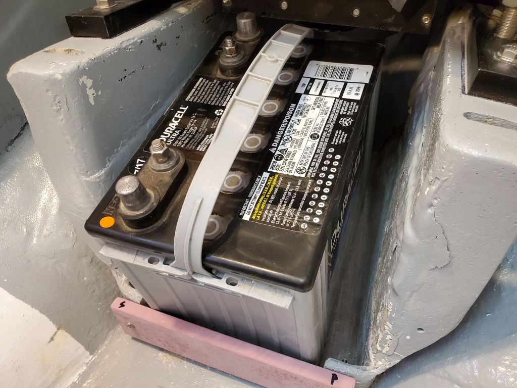
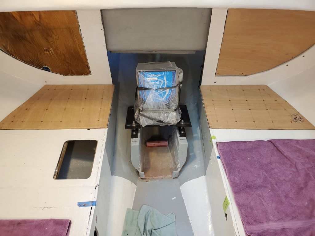
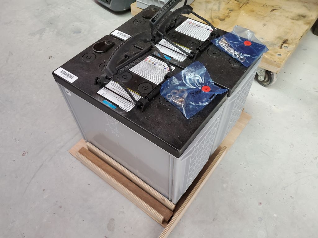
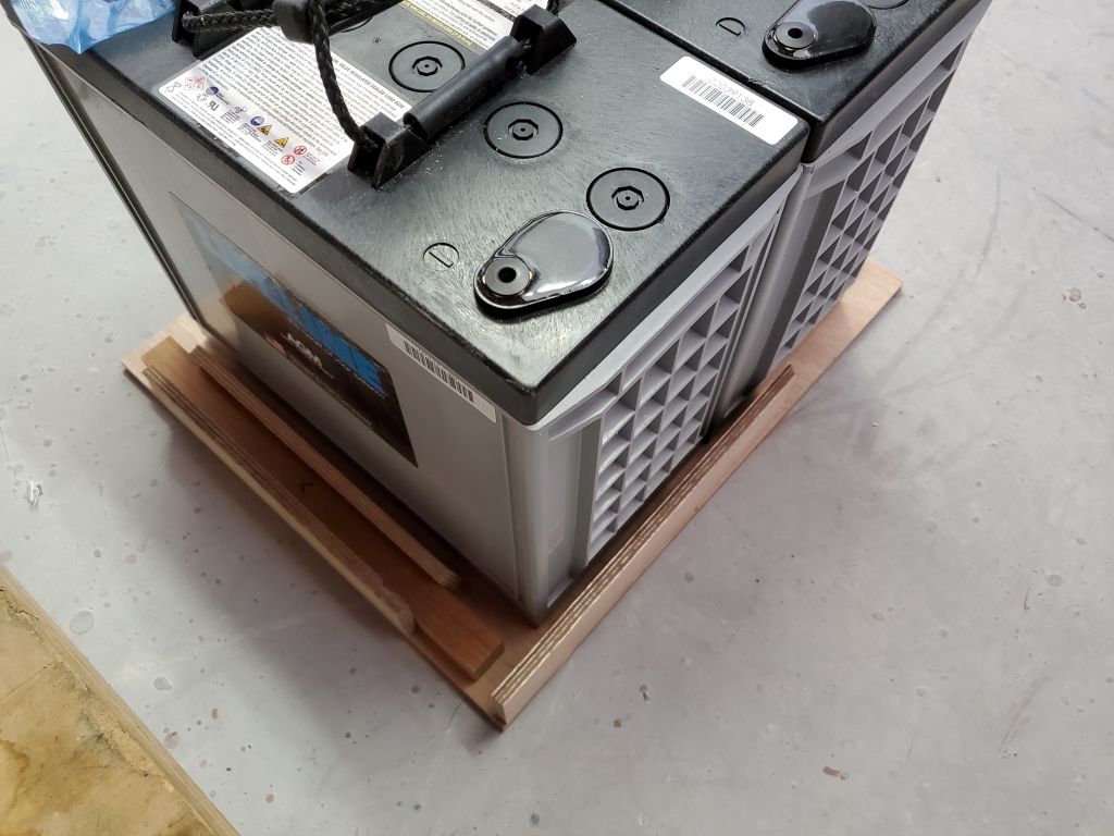
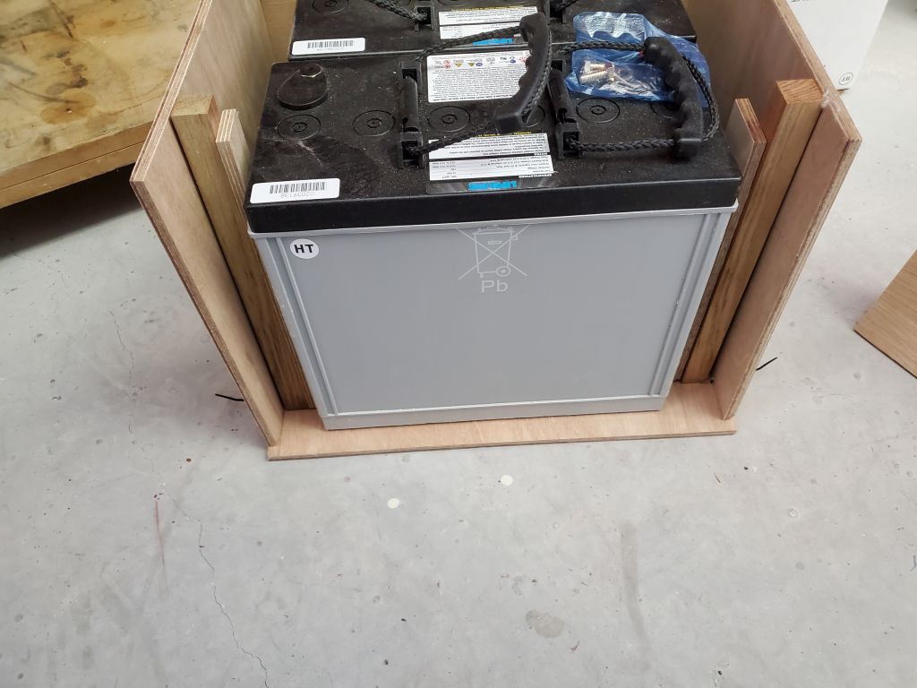
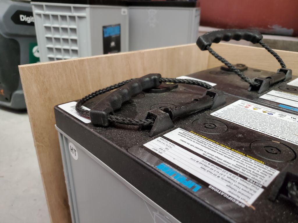
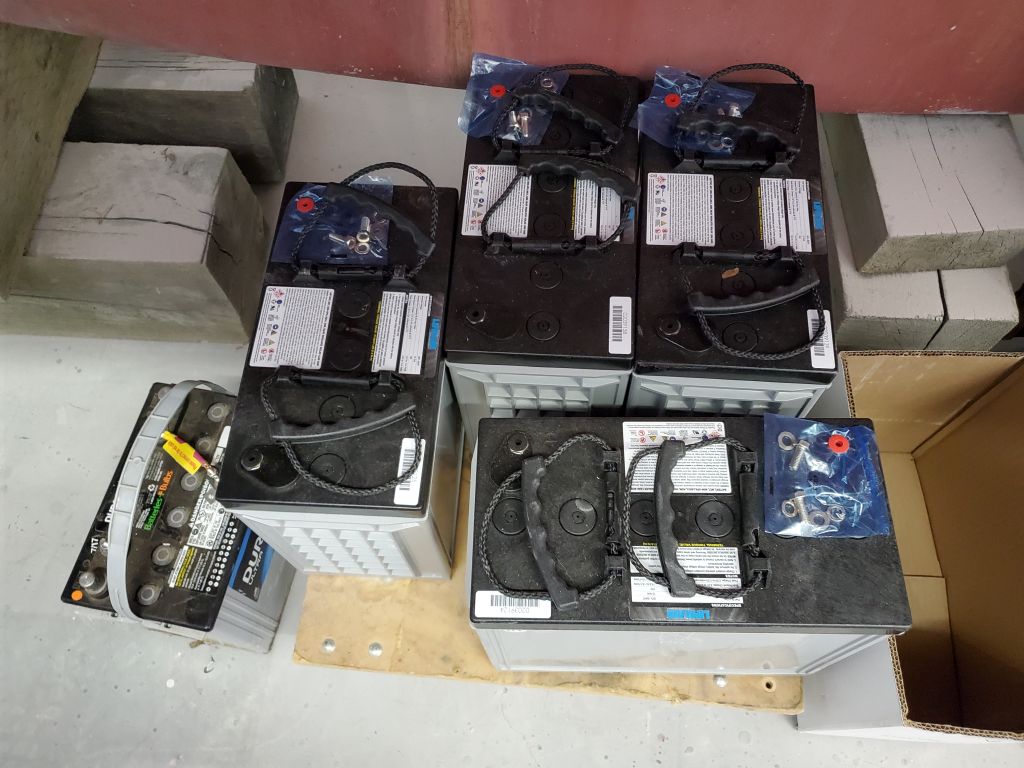
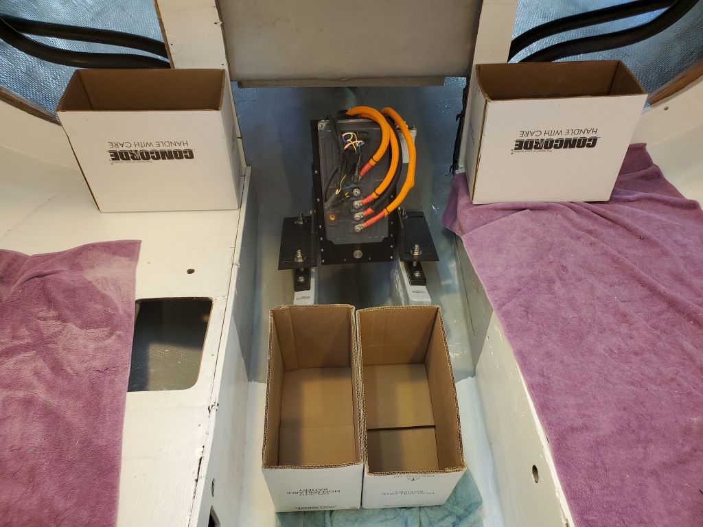
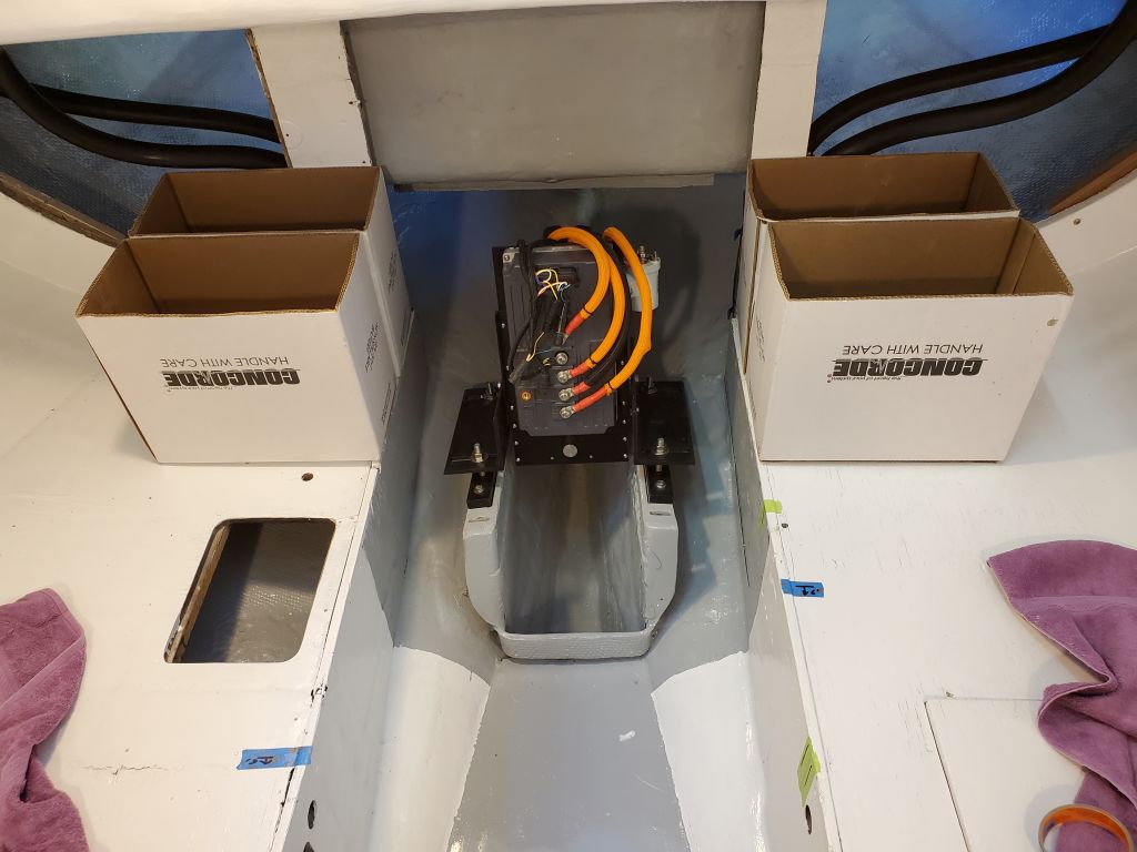
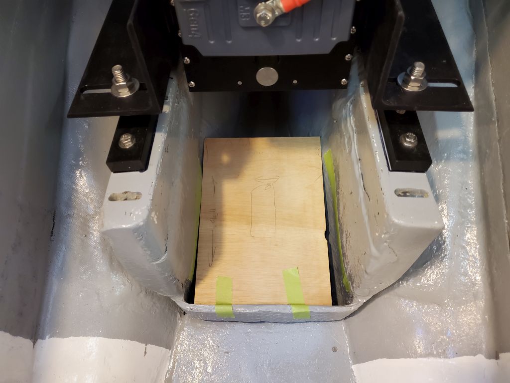
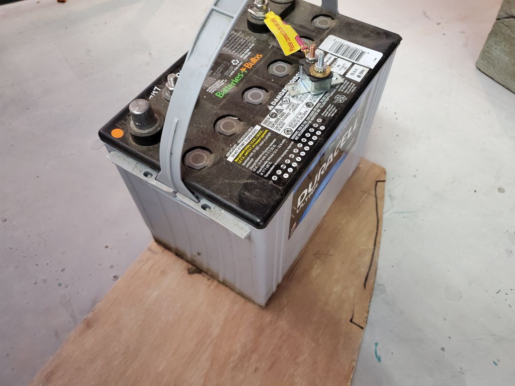
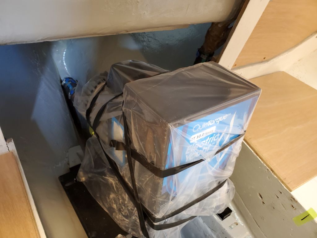
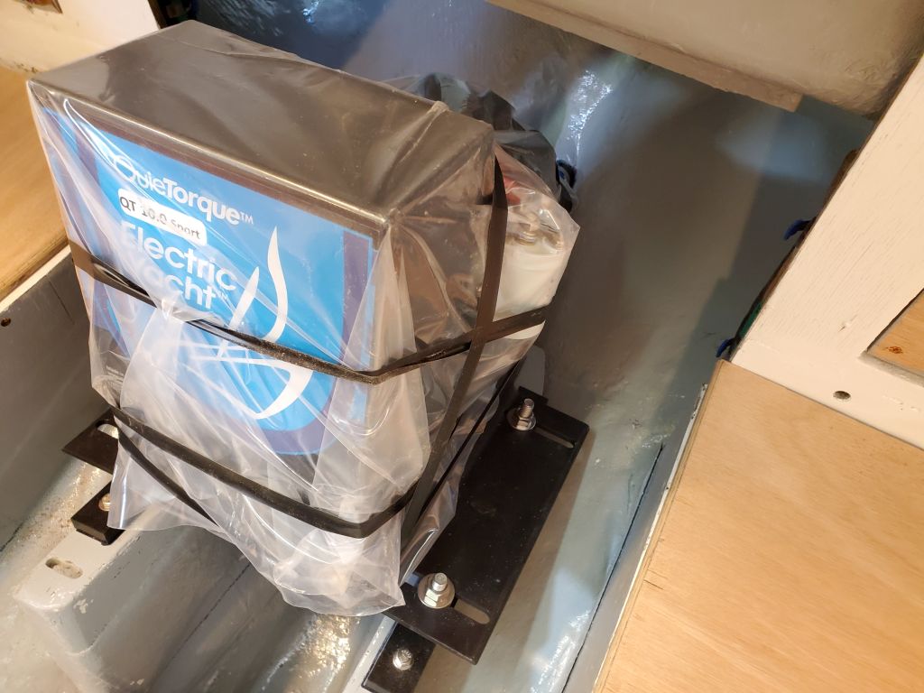
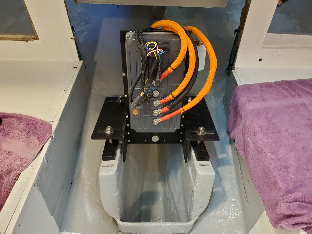
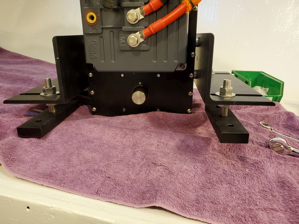
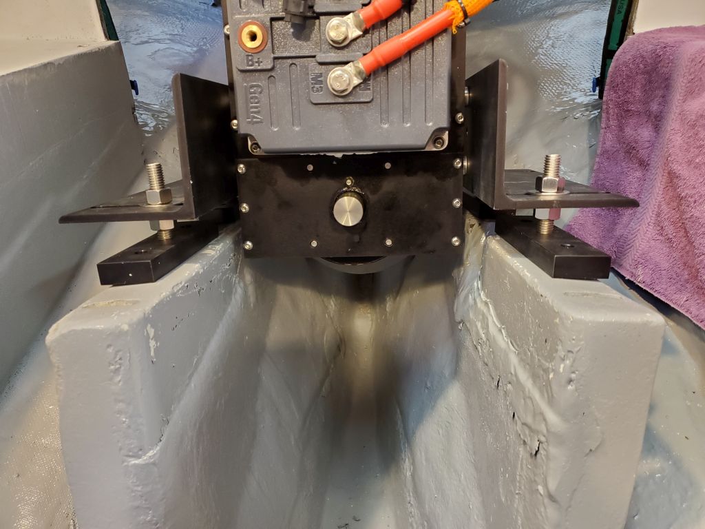
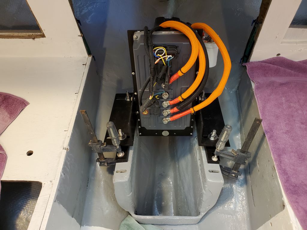
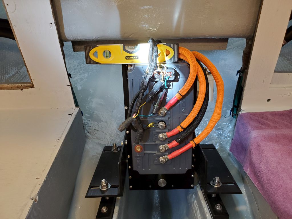
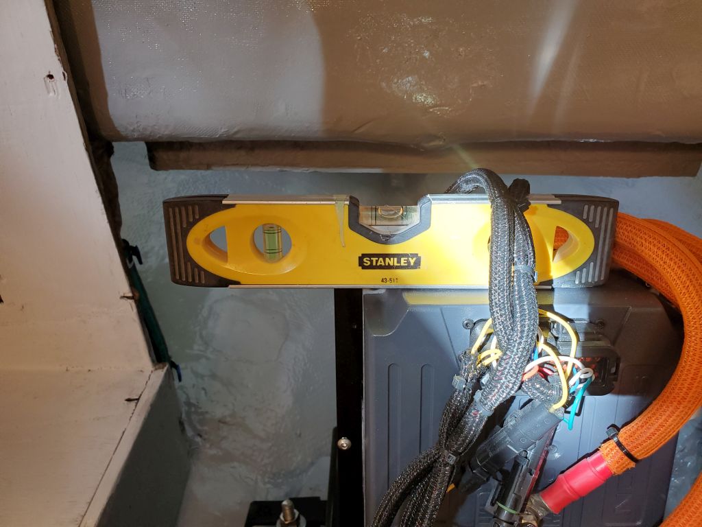
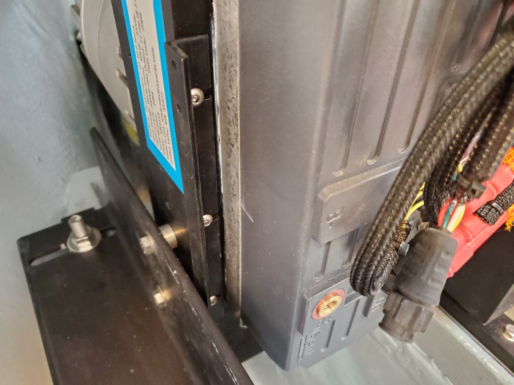
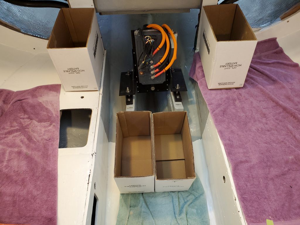
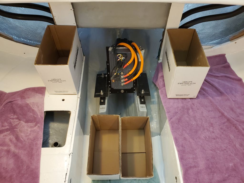
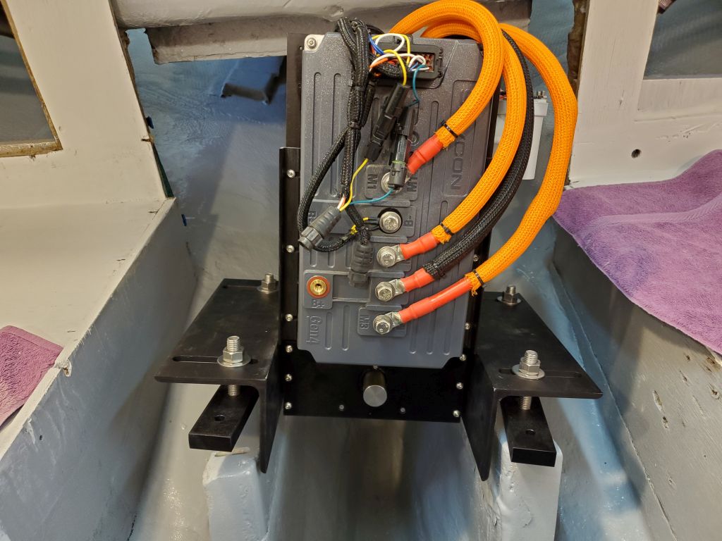
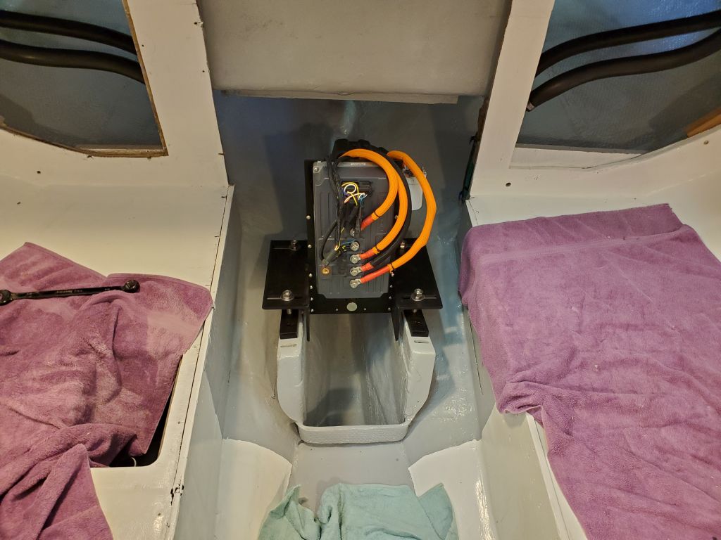
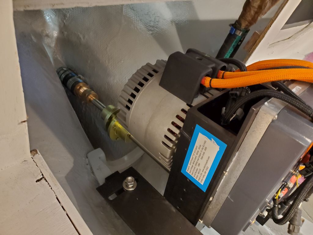
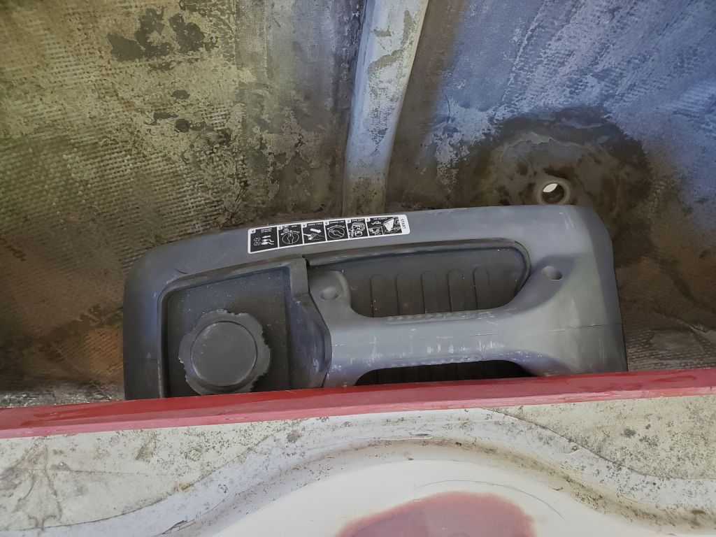
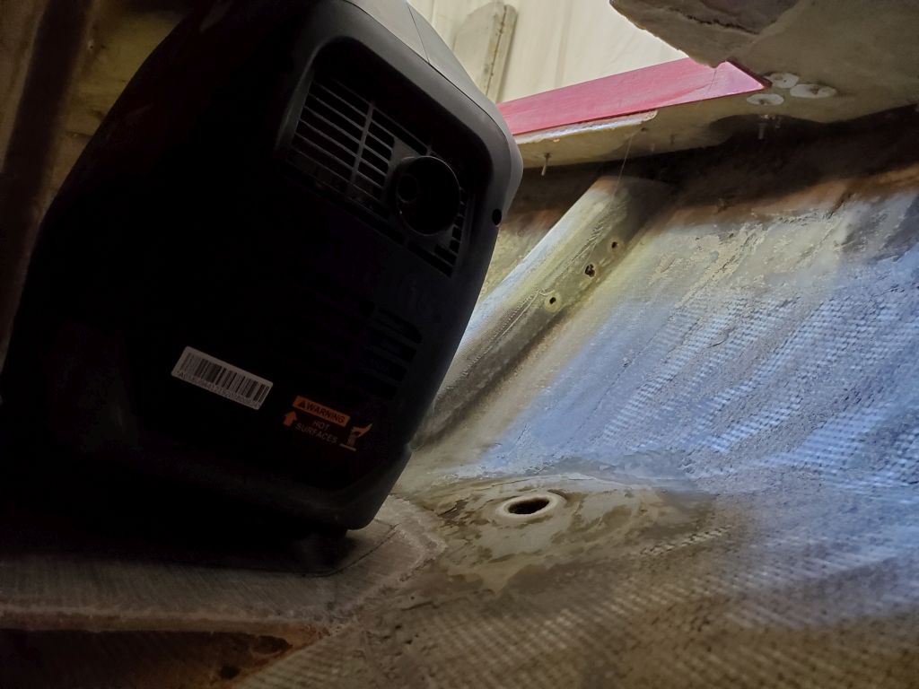
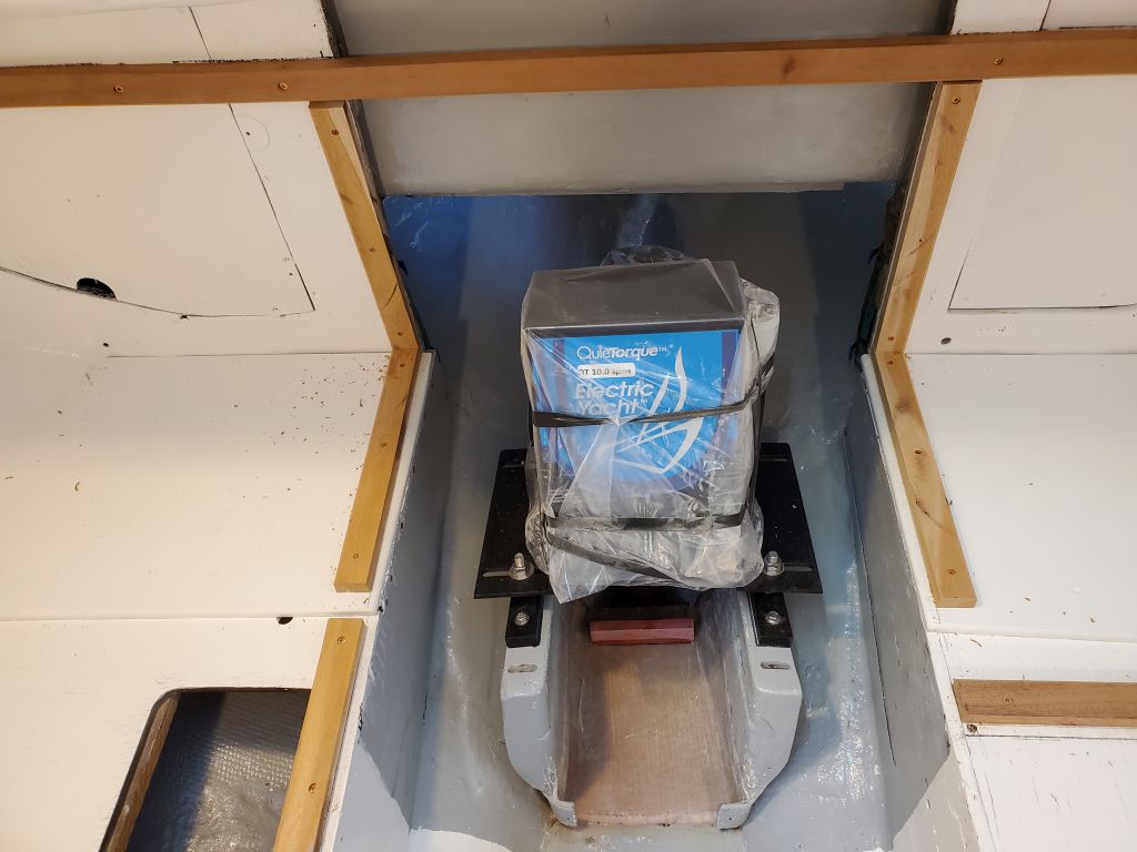
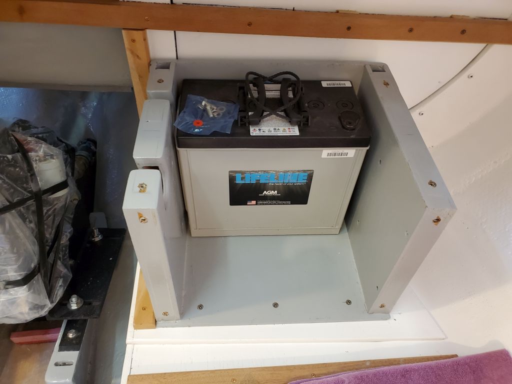
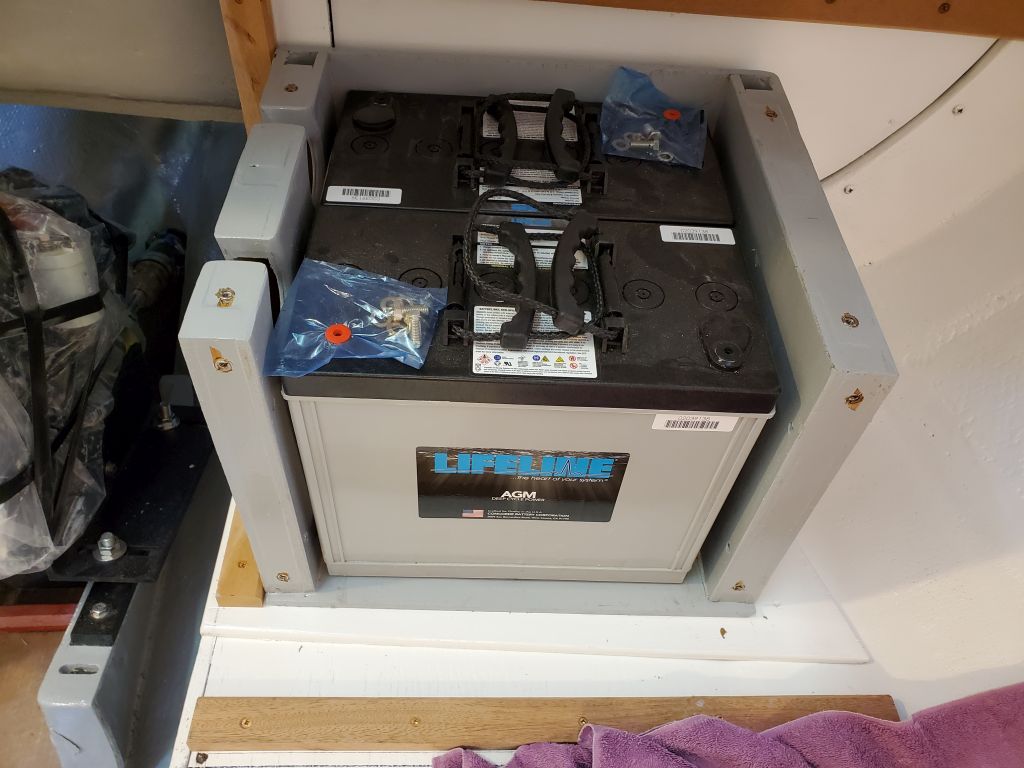
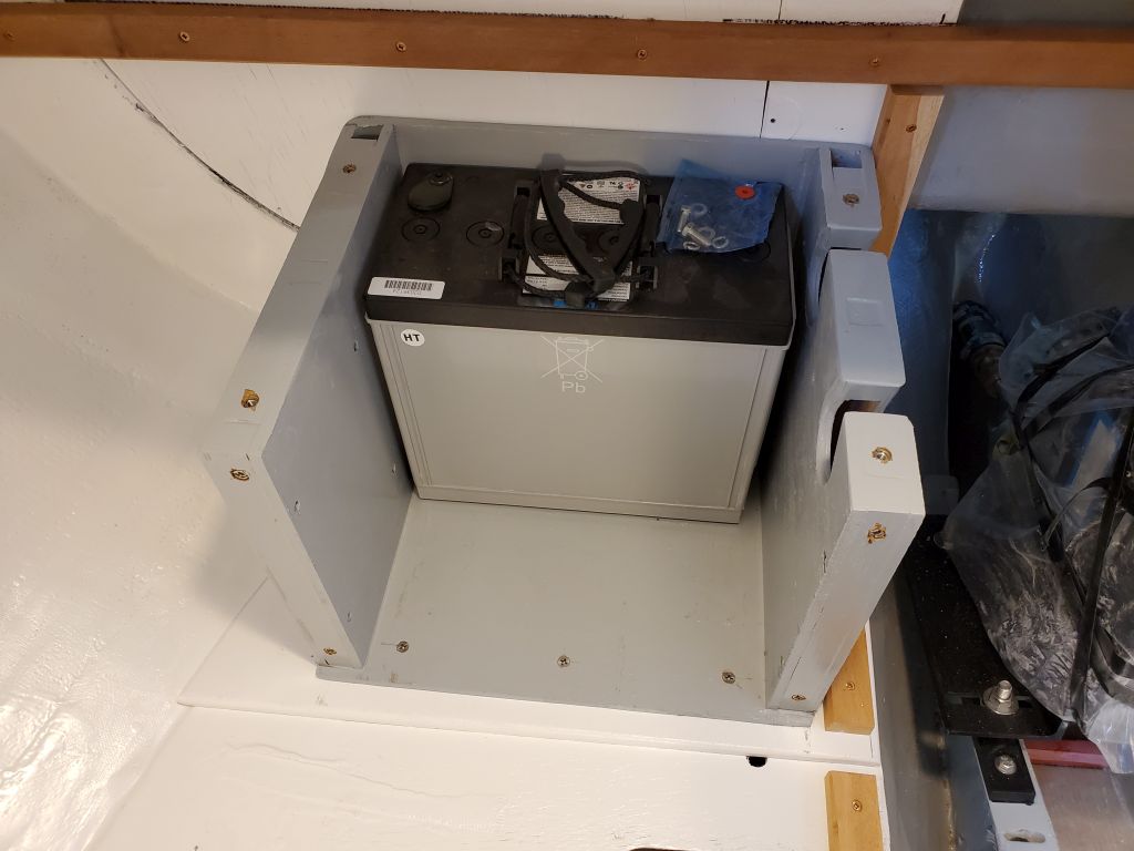
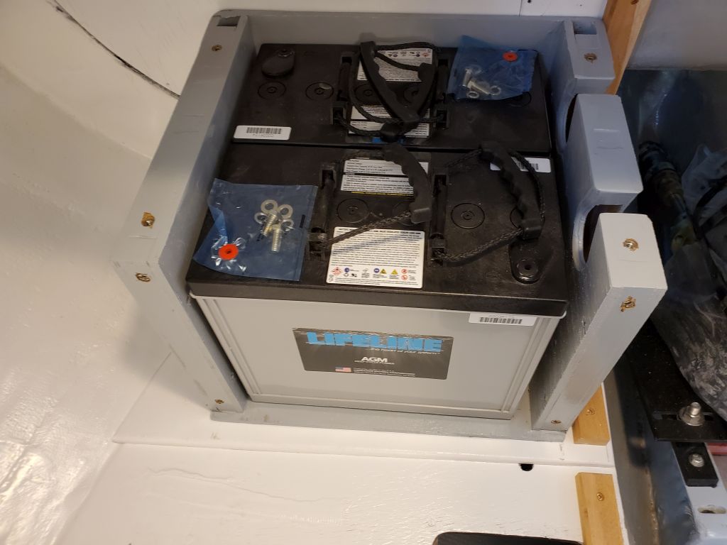
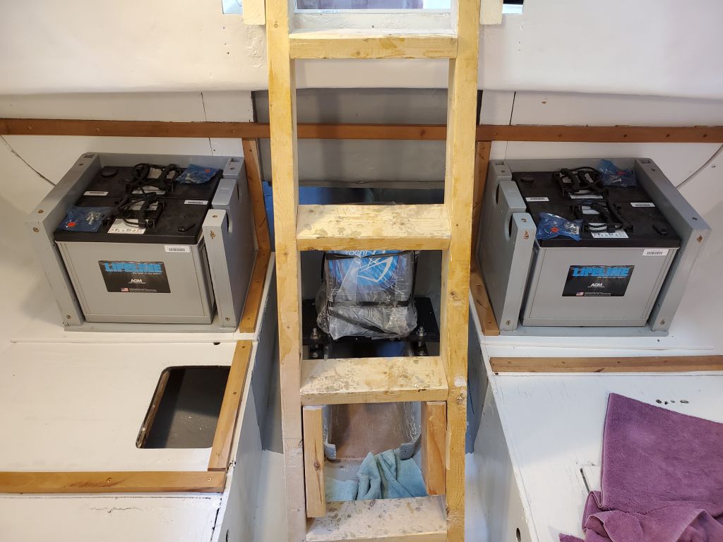
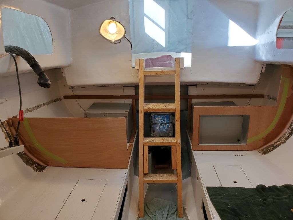
Now, working carefully to avoid excess strain on the capable, yet aging, machinery, I carried the four main batteries up and into the boat and installed them in the boxes.  If I were into video, this would be one of those stop-action montages showing the boxes filling themselves one battery at a time.  Astute viewers might notice that I actually reversed the direction of the first battery after I took the photo (as in the third photo), as upon reflection and consideration of the wiring it seemed that having the terminals for each battery end up at the fore and aft edges of the box would work out better.

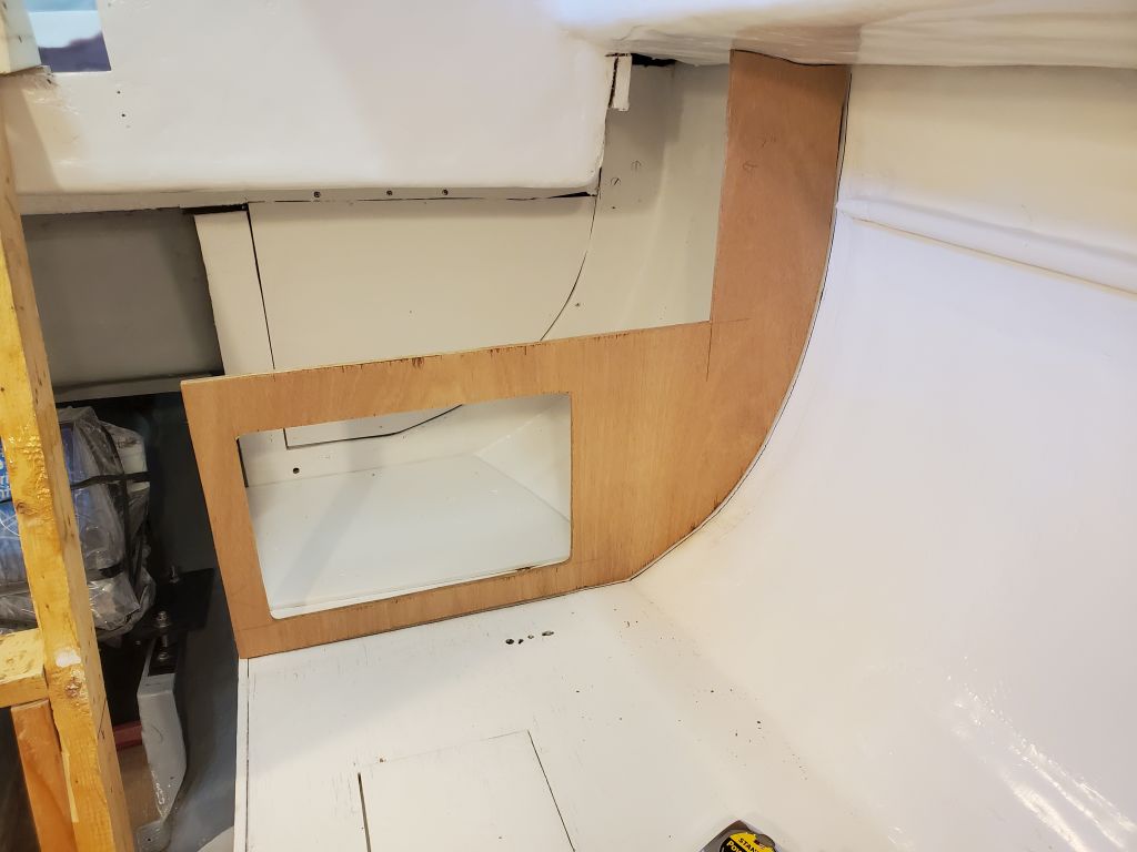
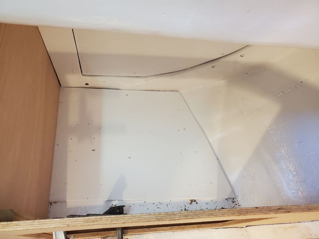
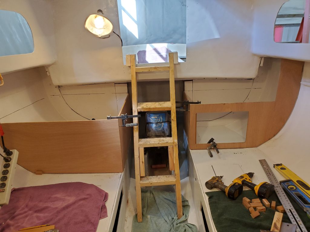
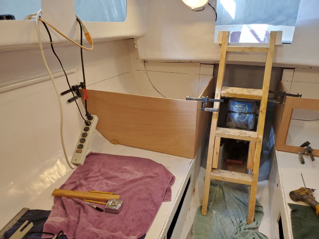
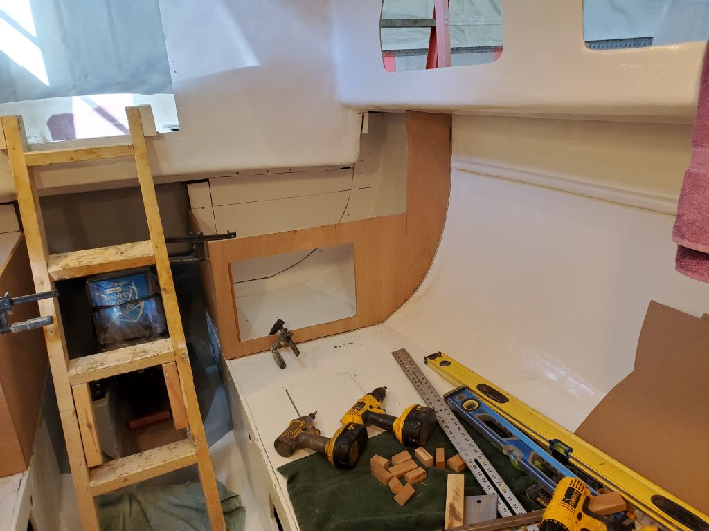
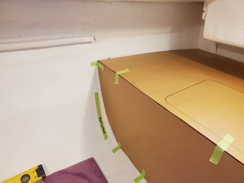
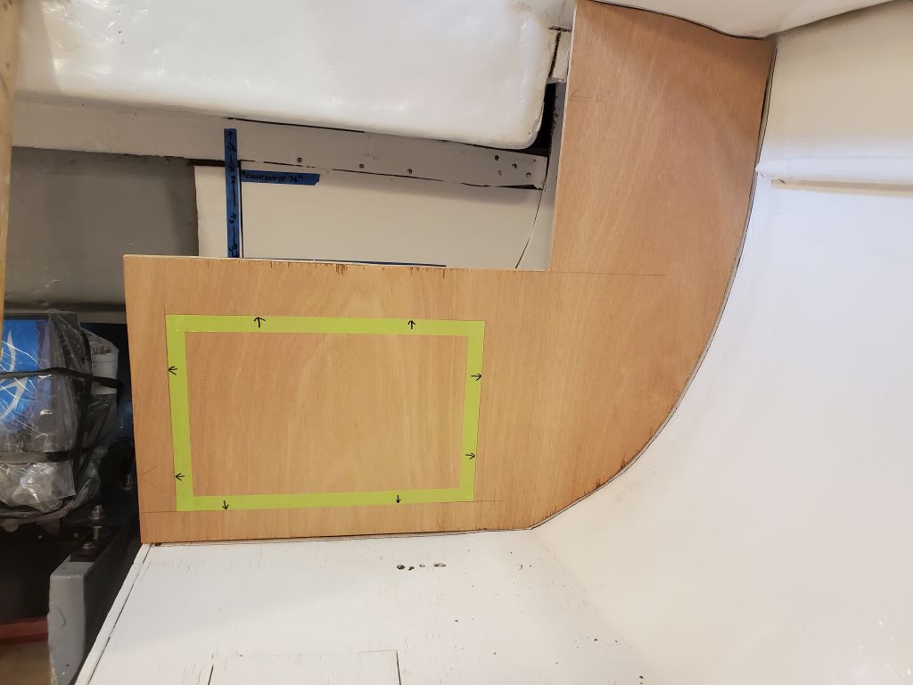
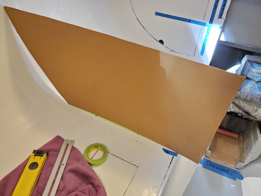
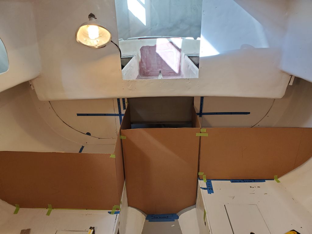
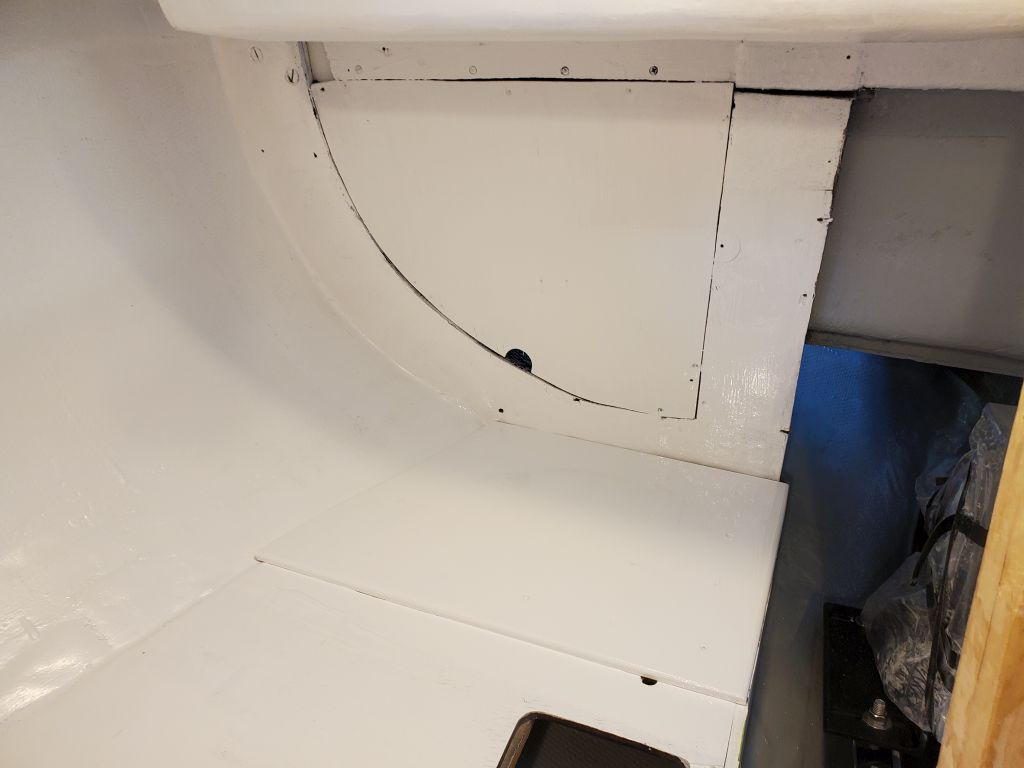
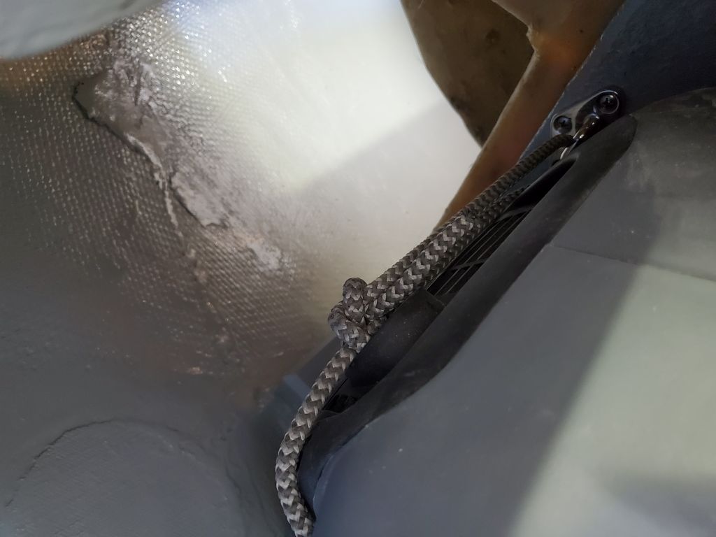
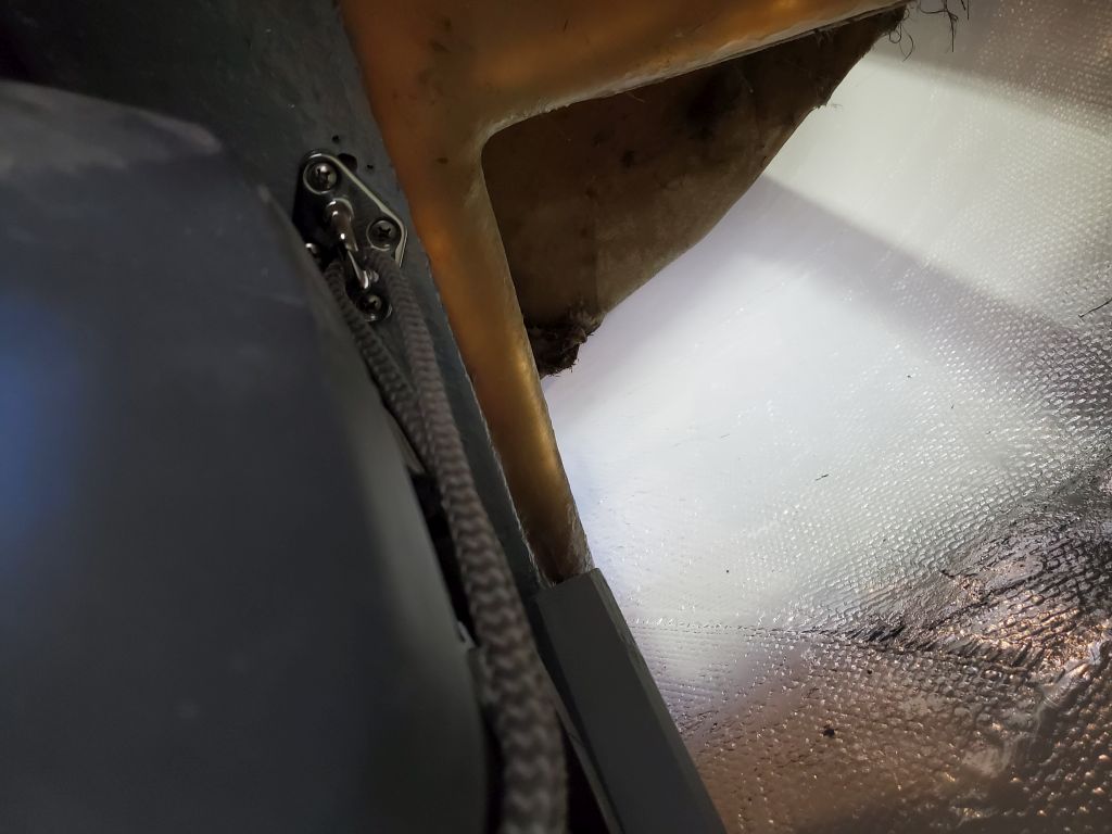
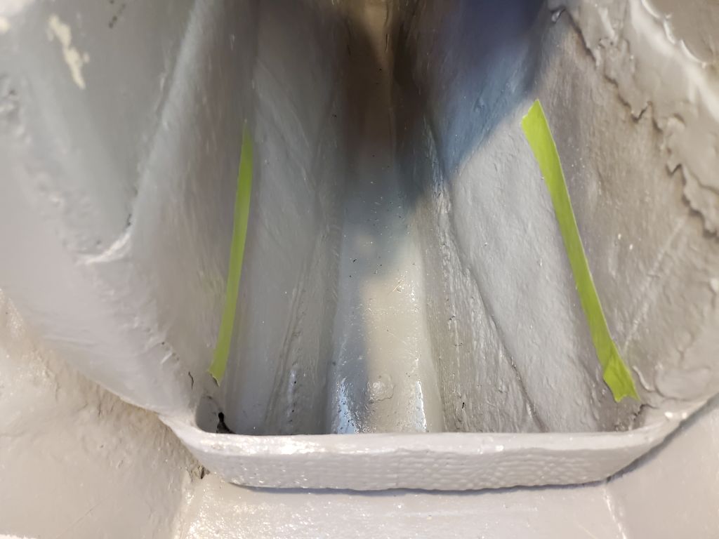
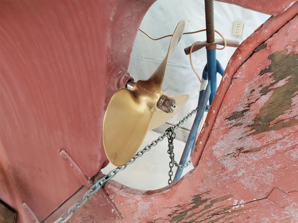
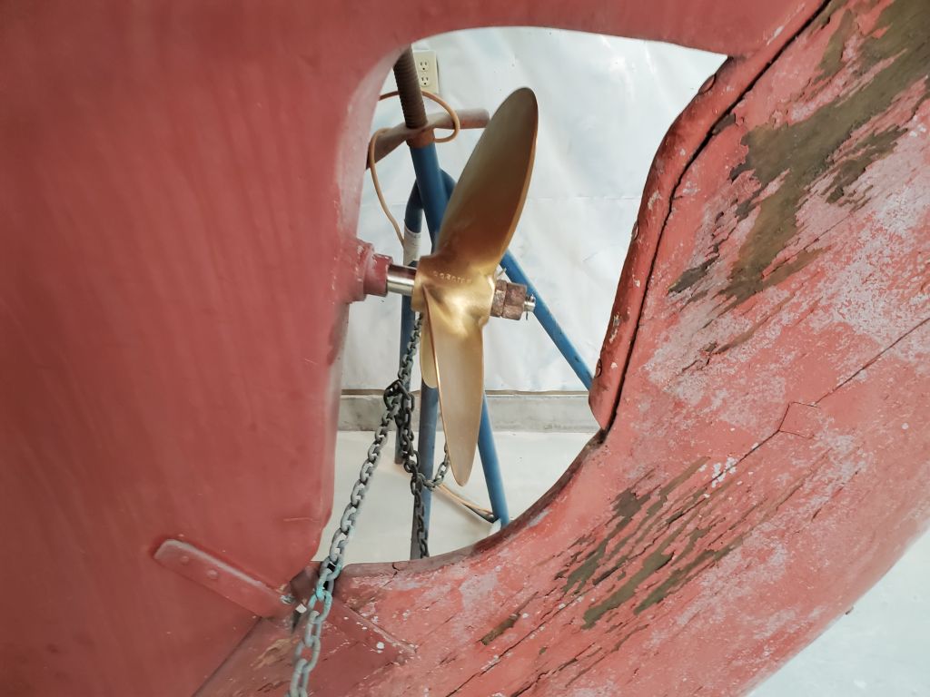
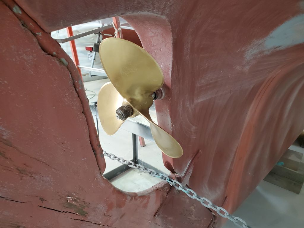
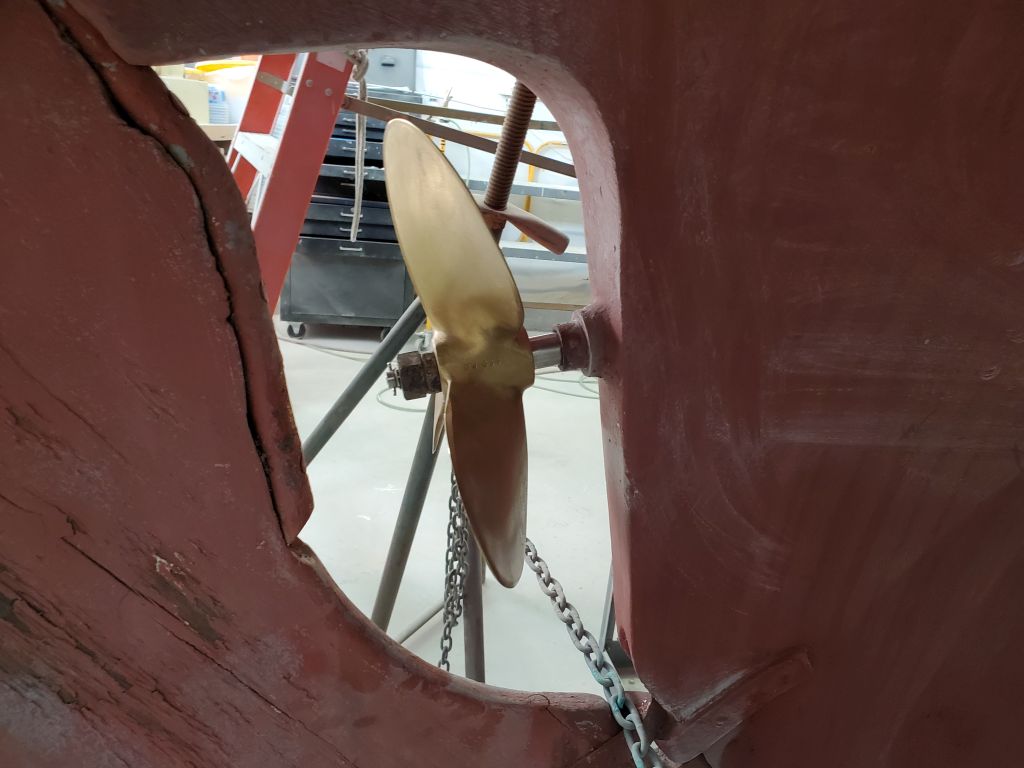
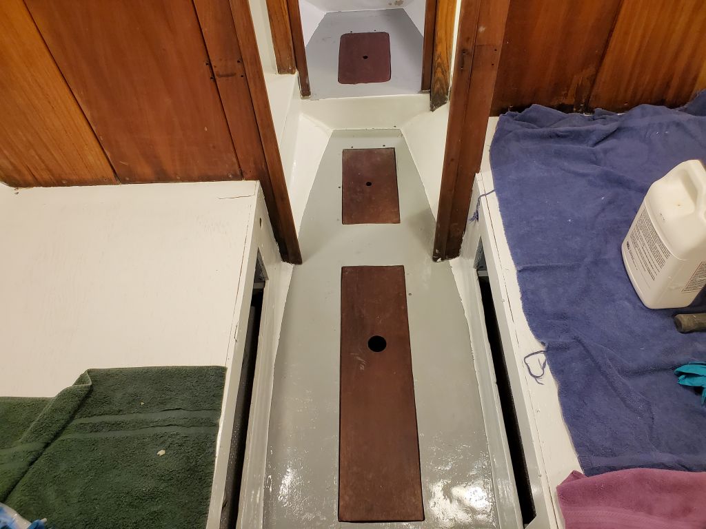
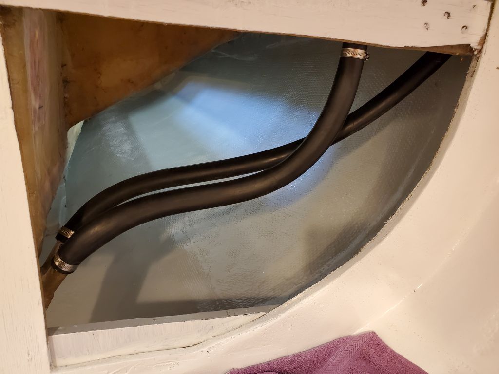
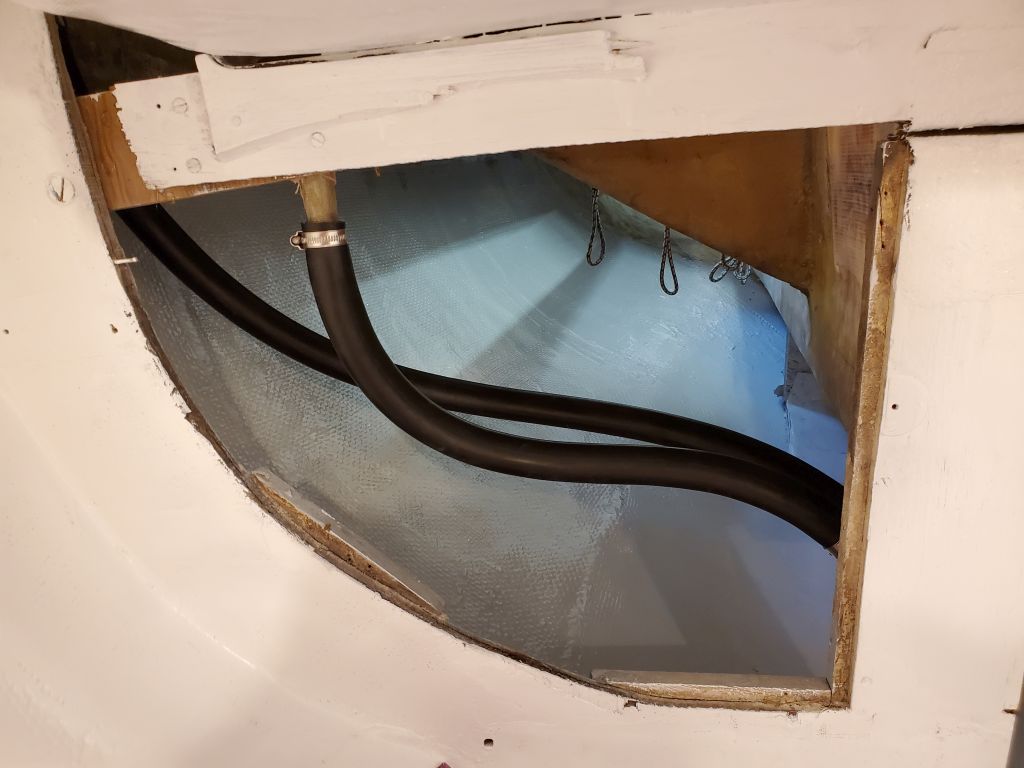
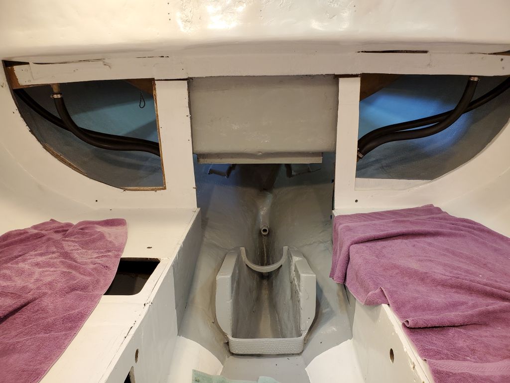
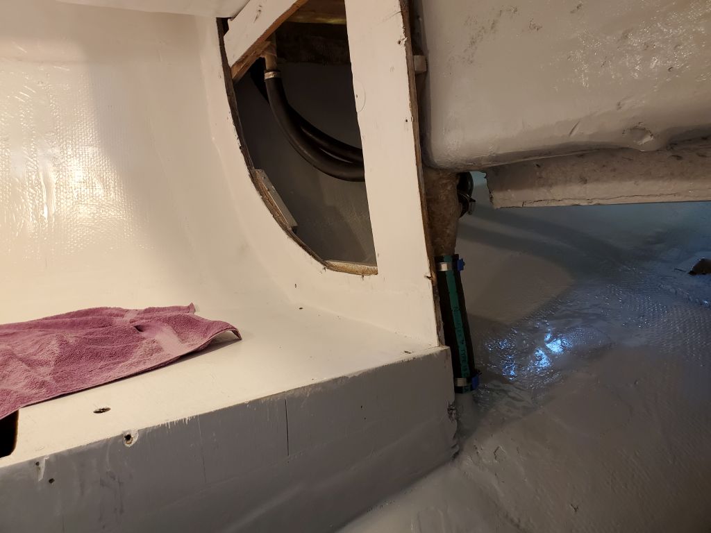
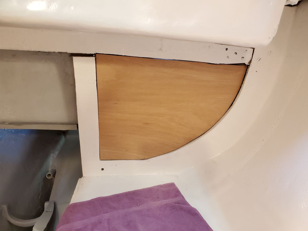
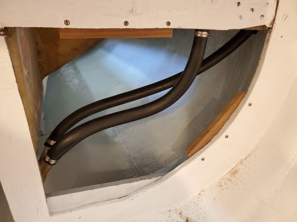
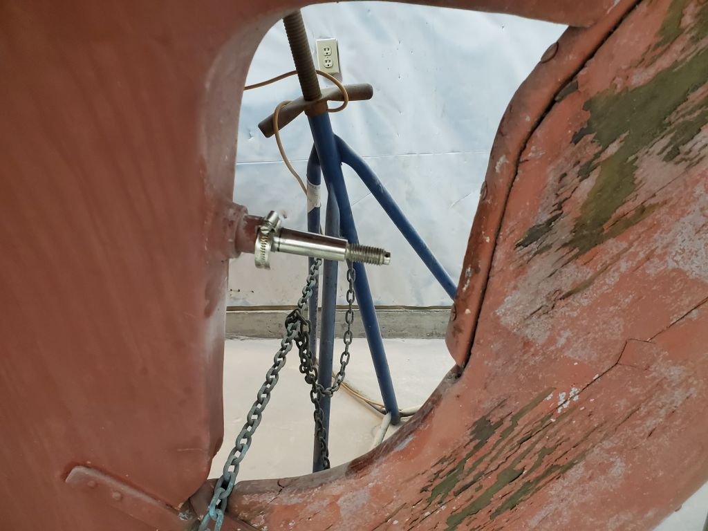
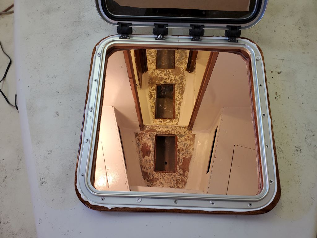
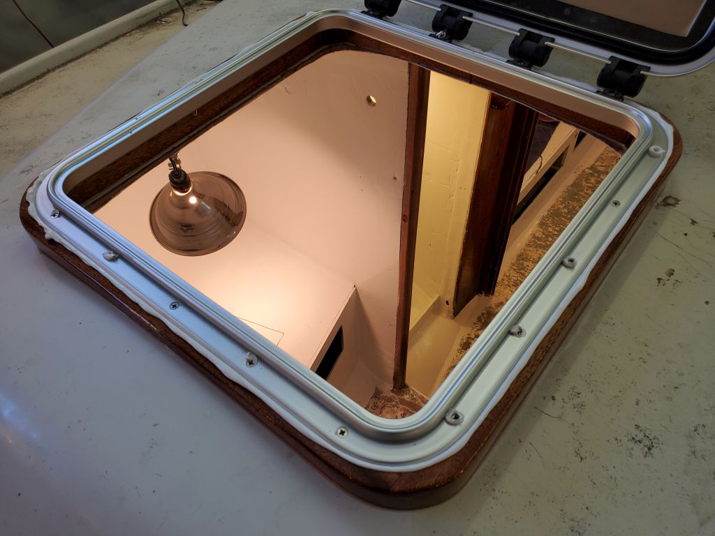
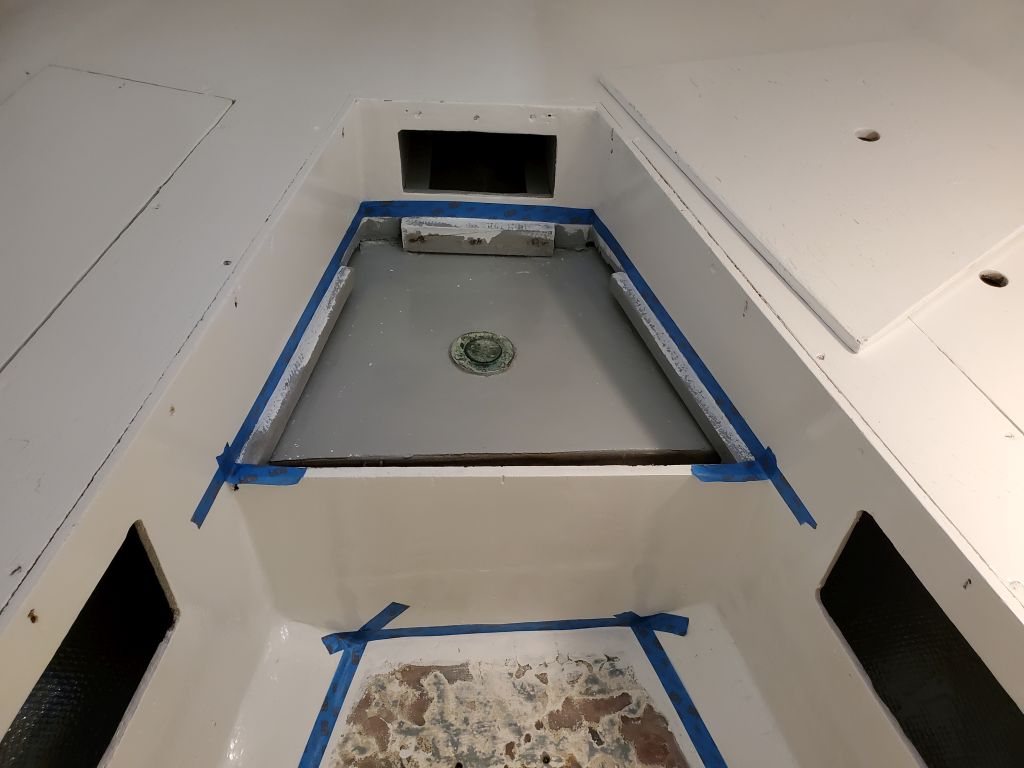
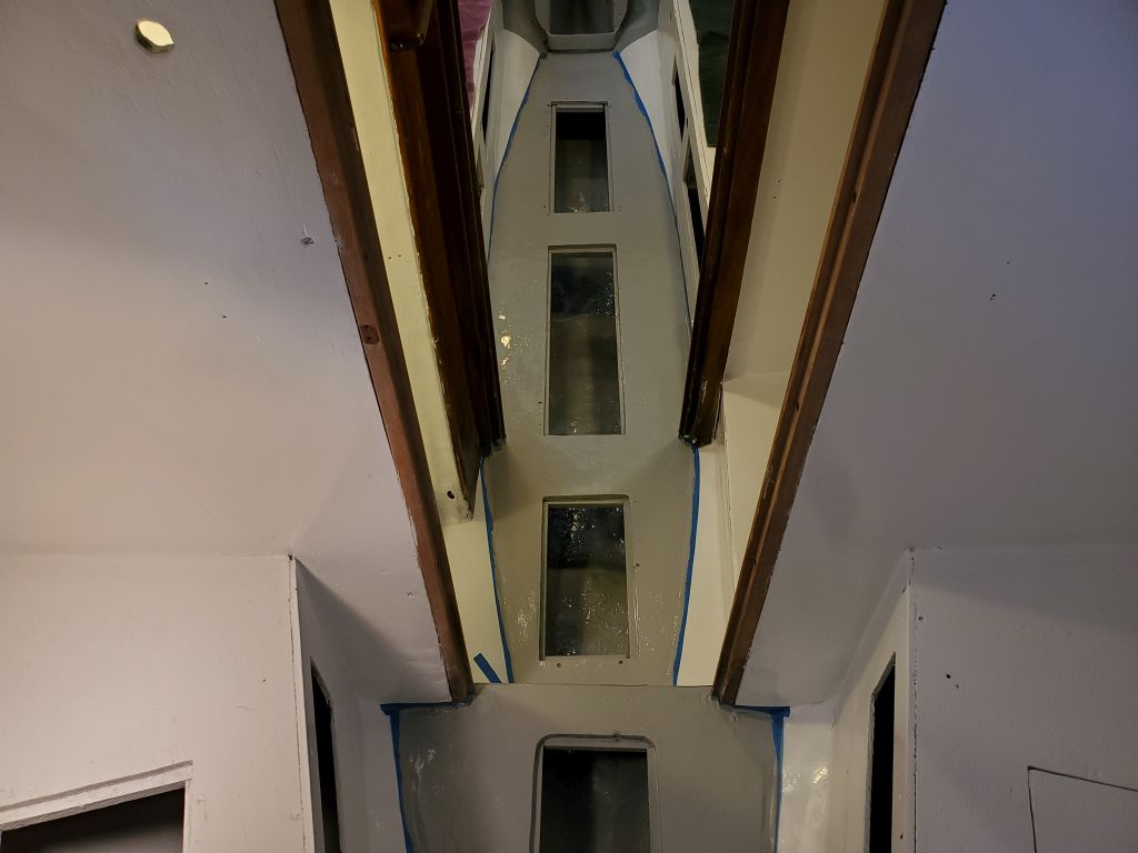
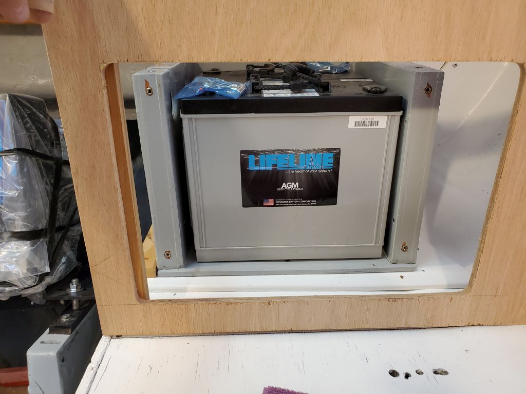
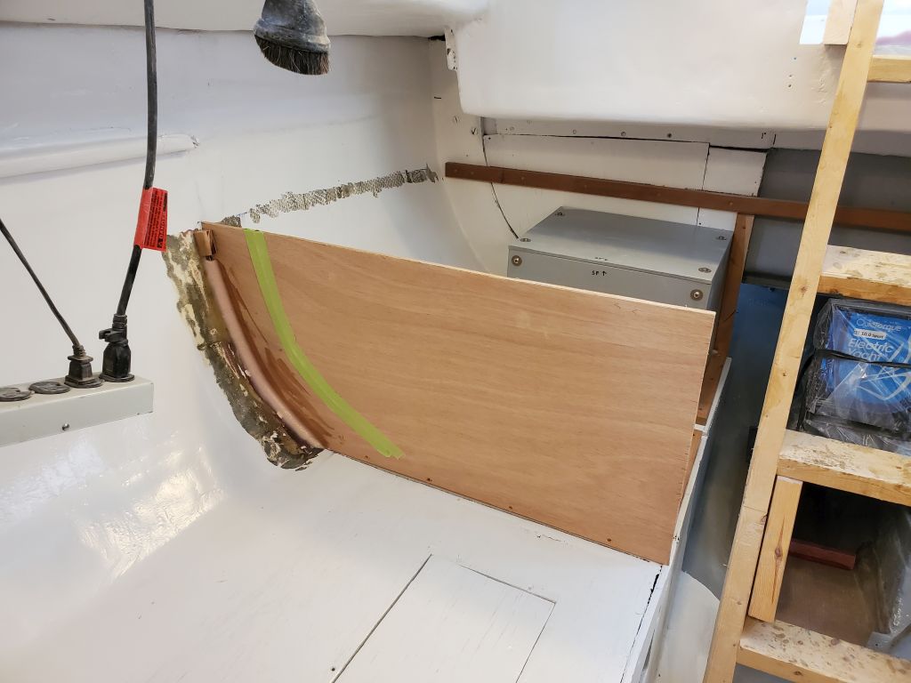
I was pleased with the expansiveness of the opening in the port bulkhead, which clearly would give adequate room to move the batteries as well as good access to the remainder of the locker.

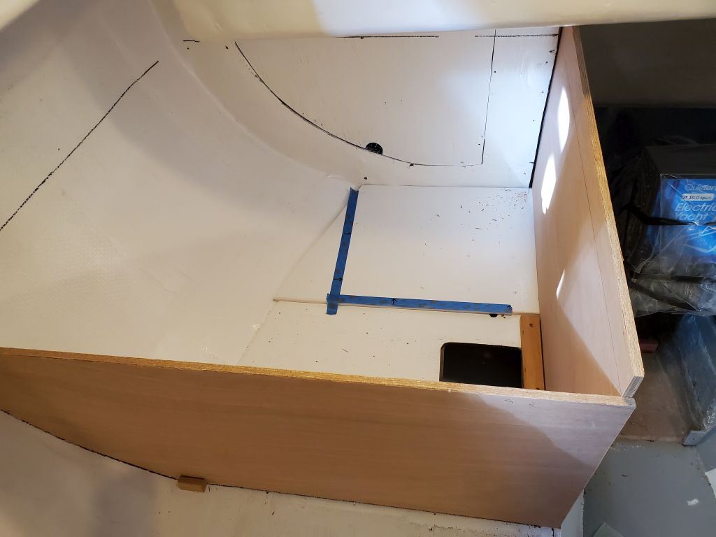
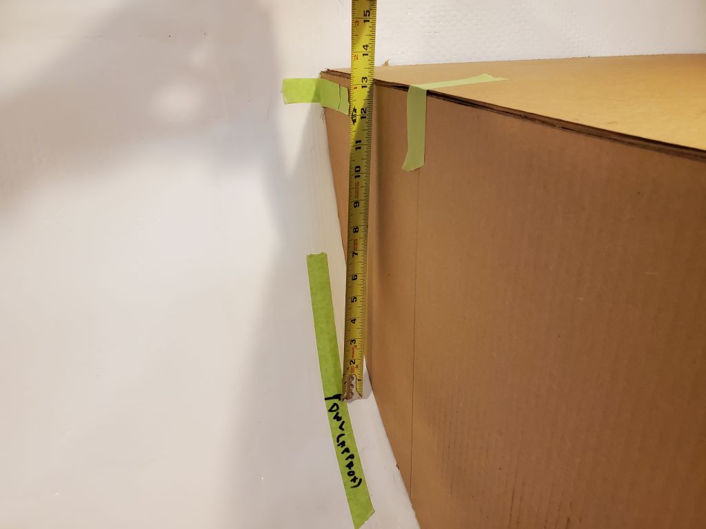
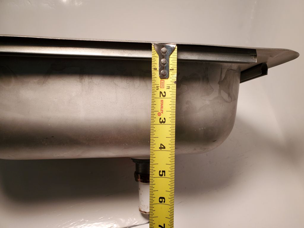
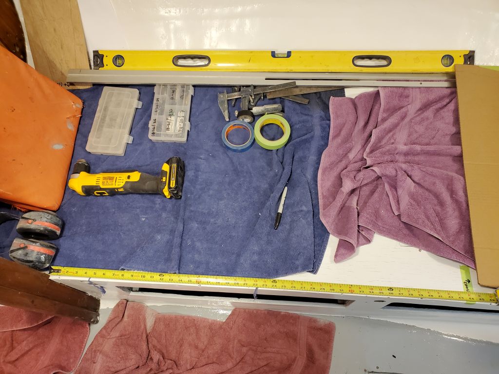
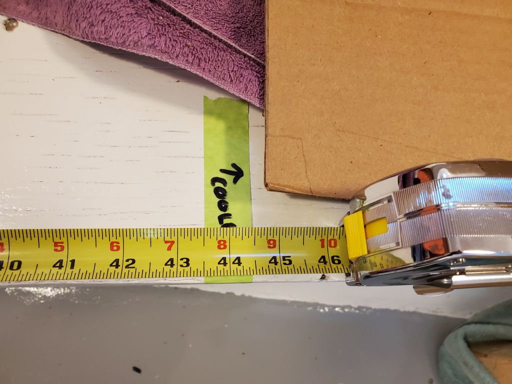
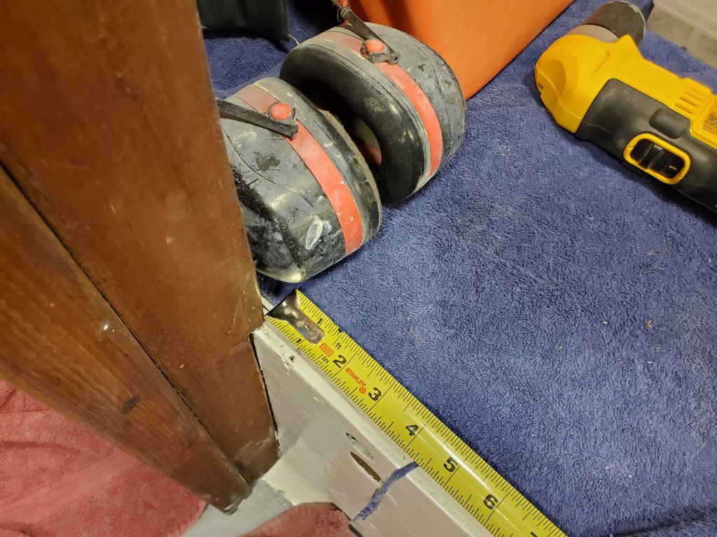
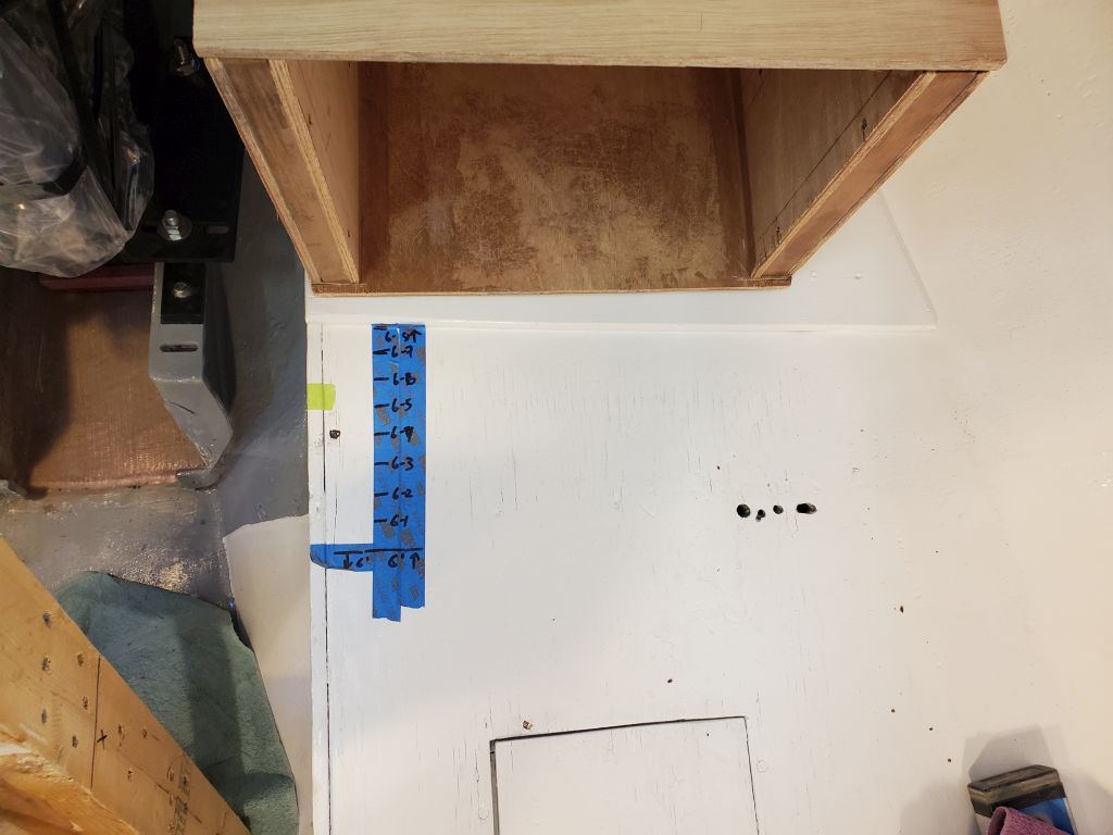
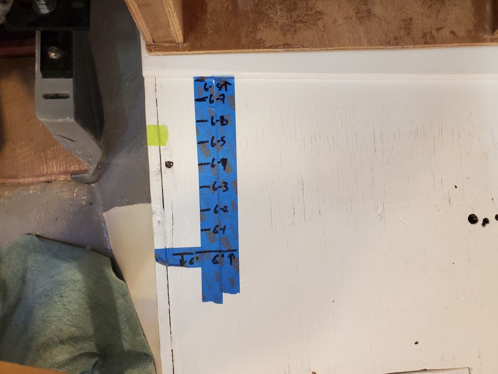
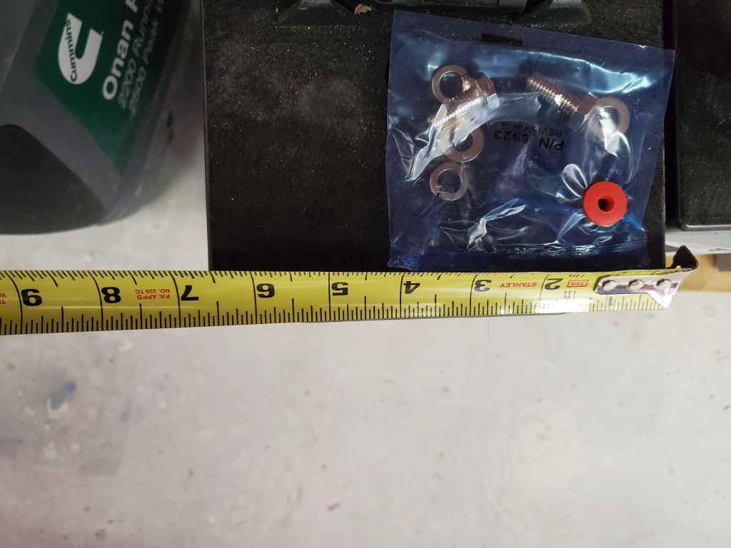
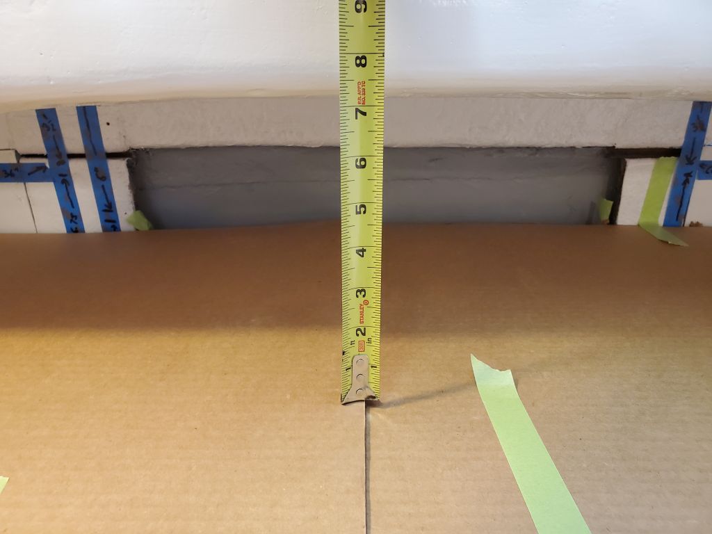
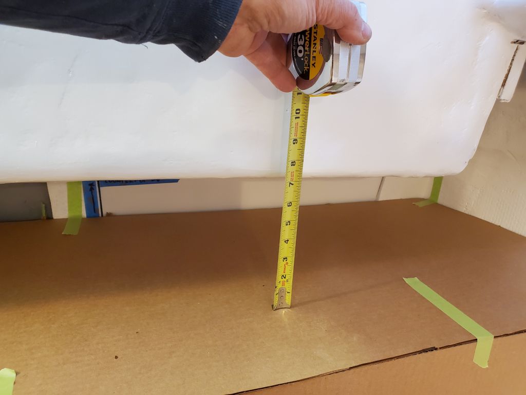
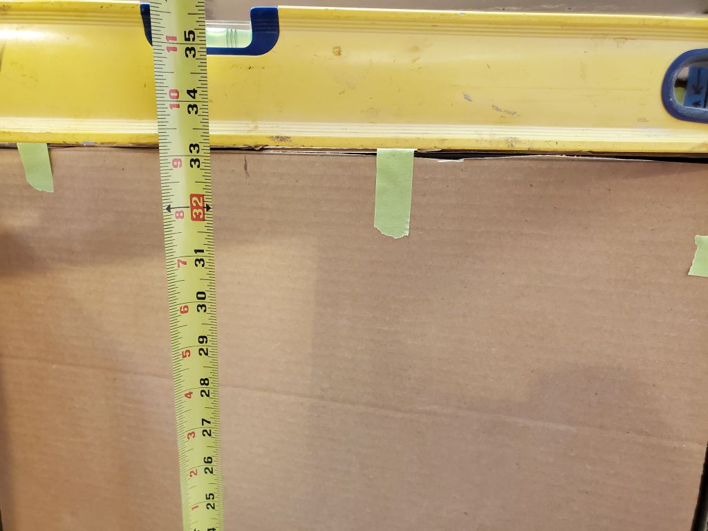
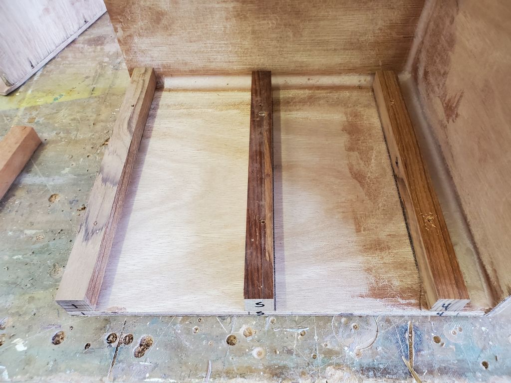
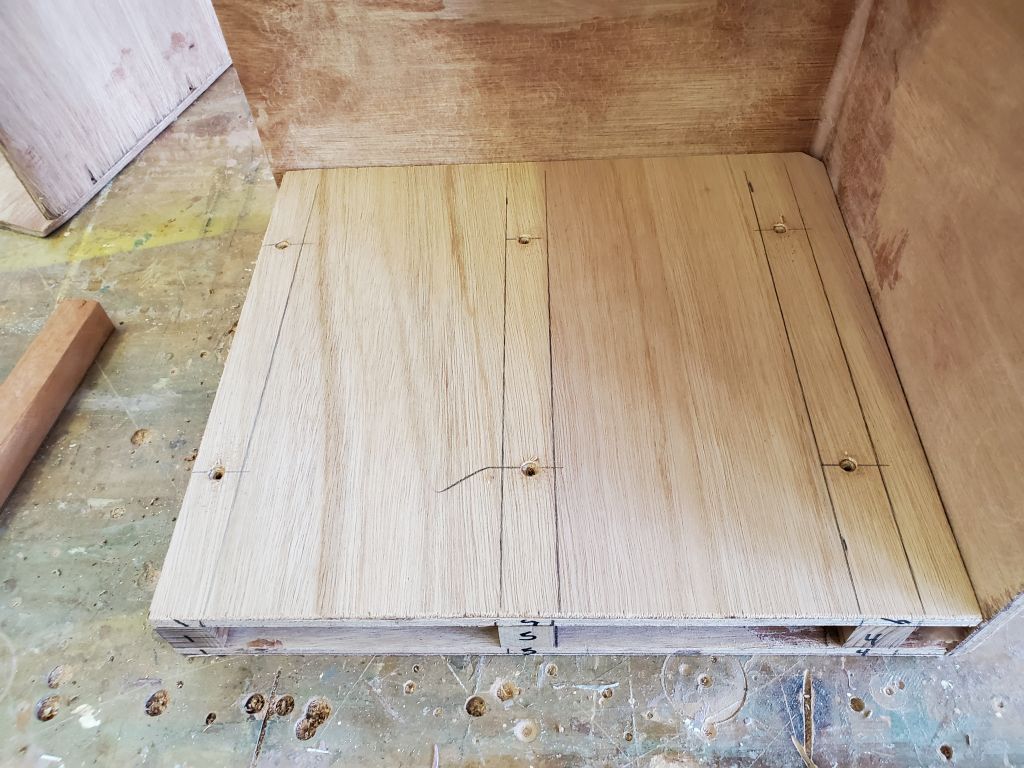
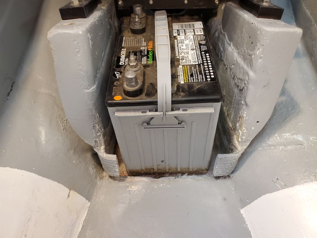
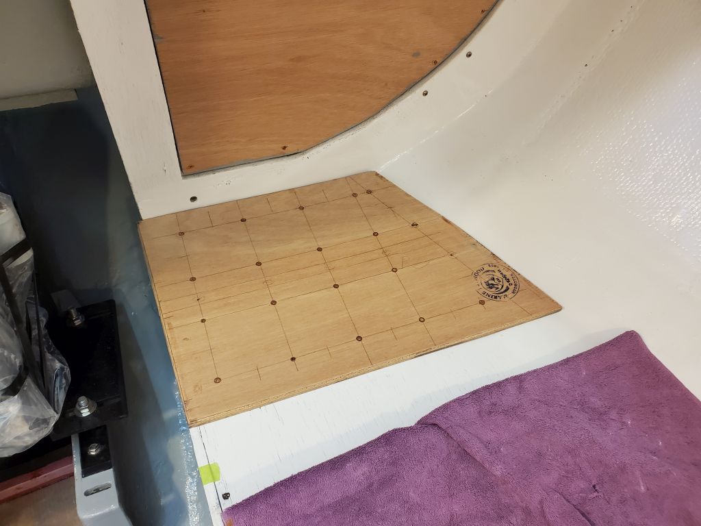
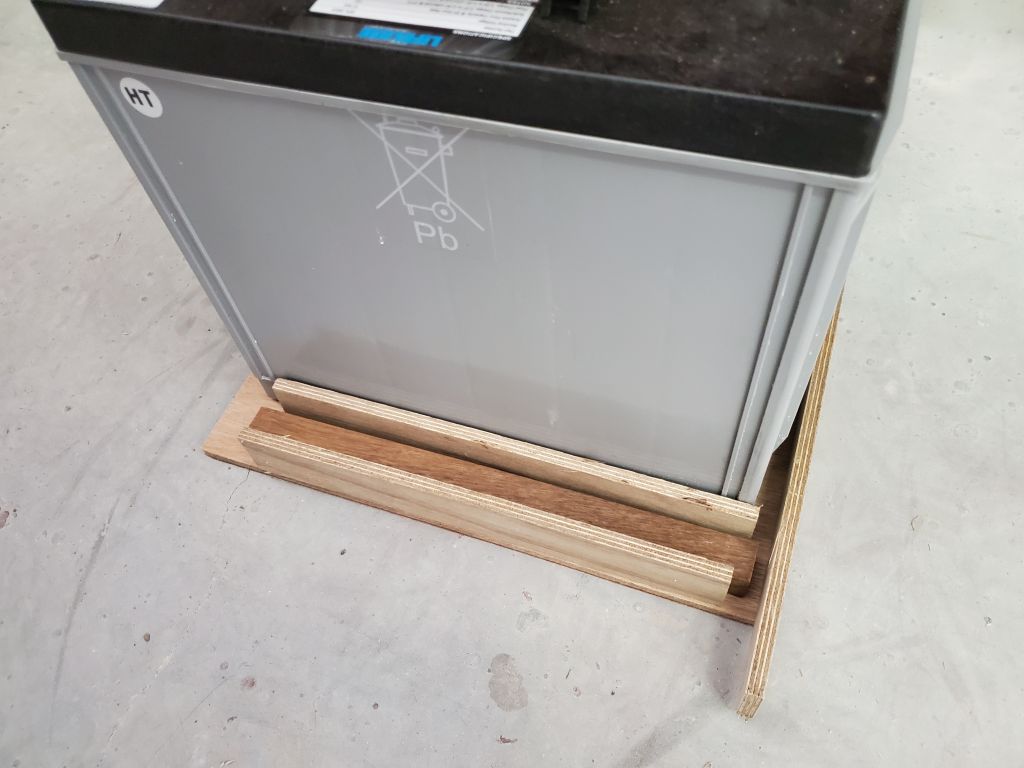
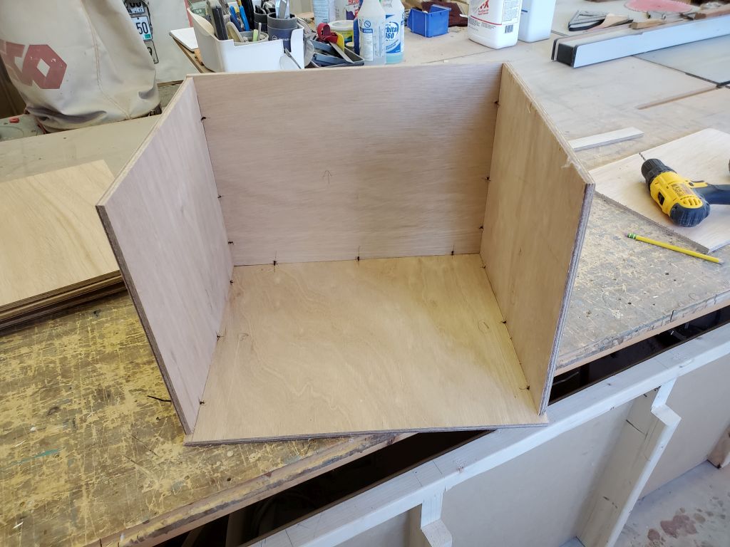
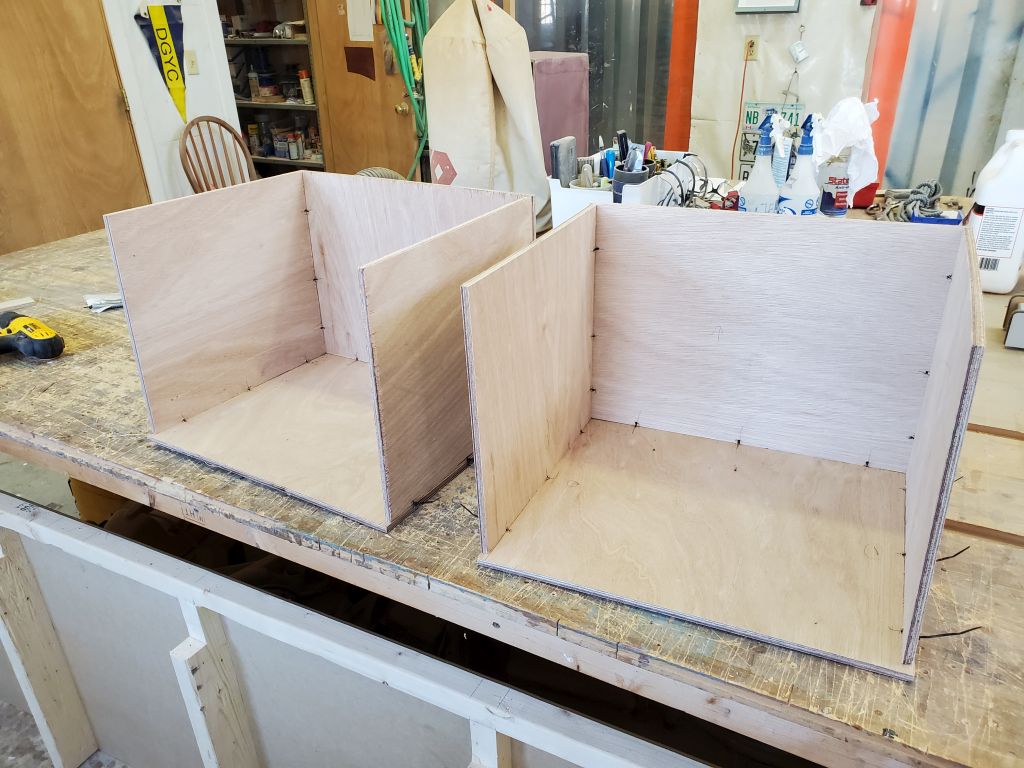
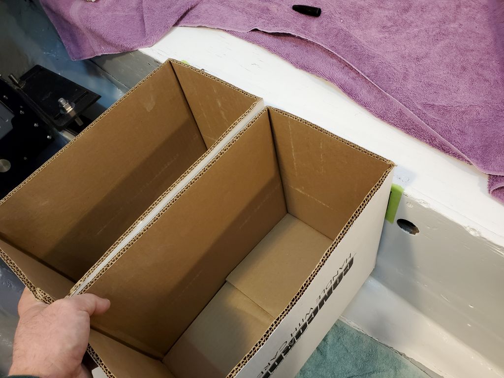
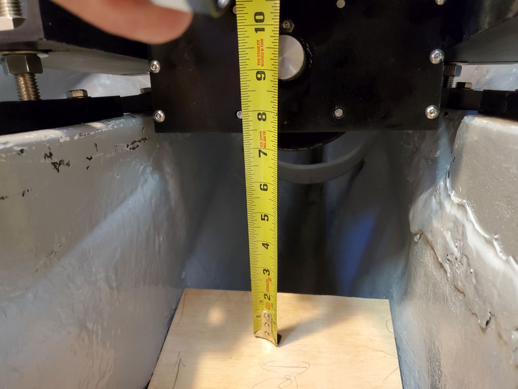
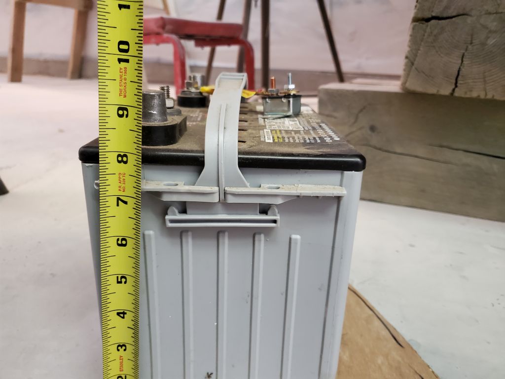
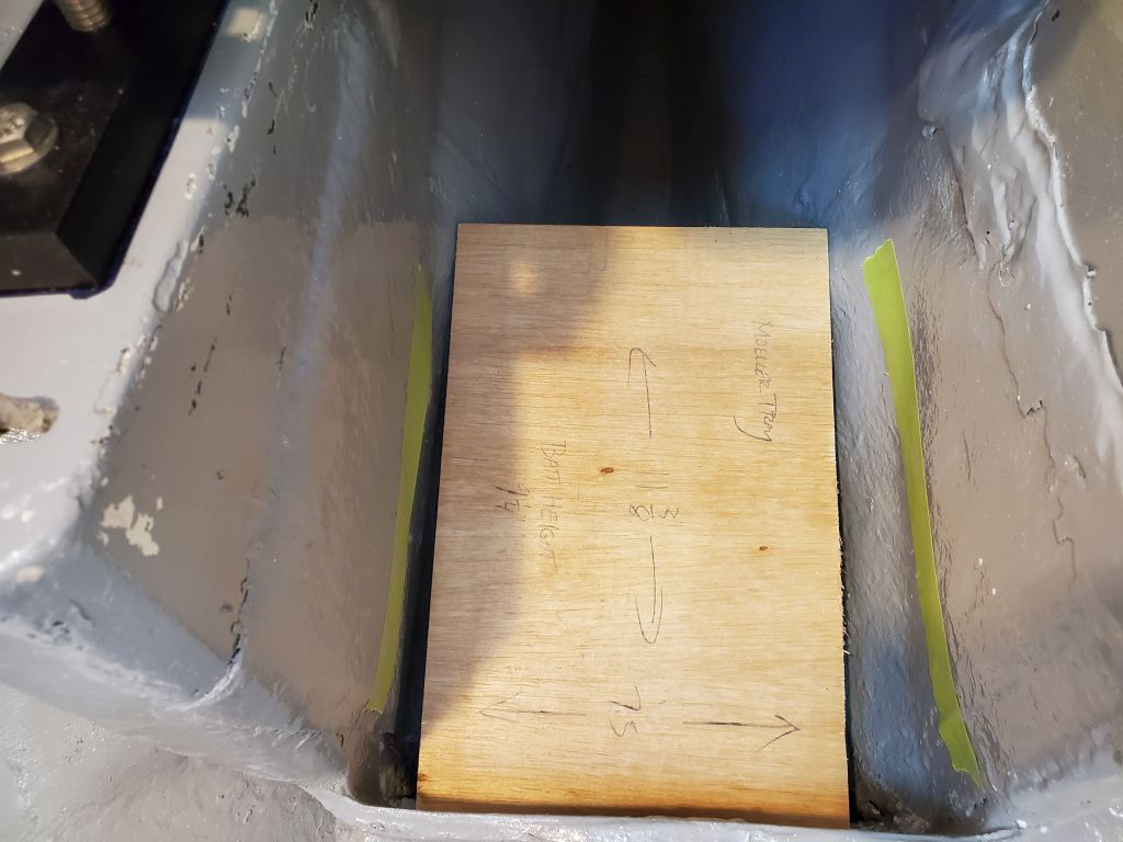
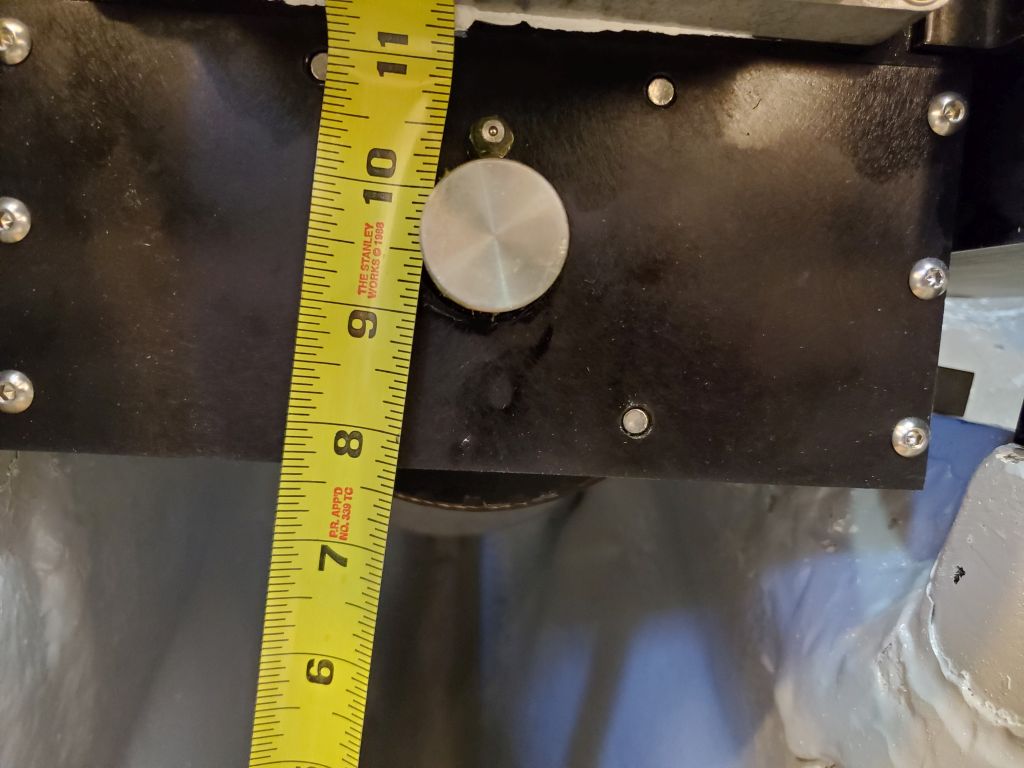
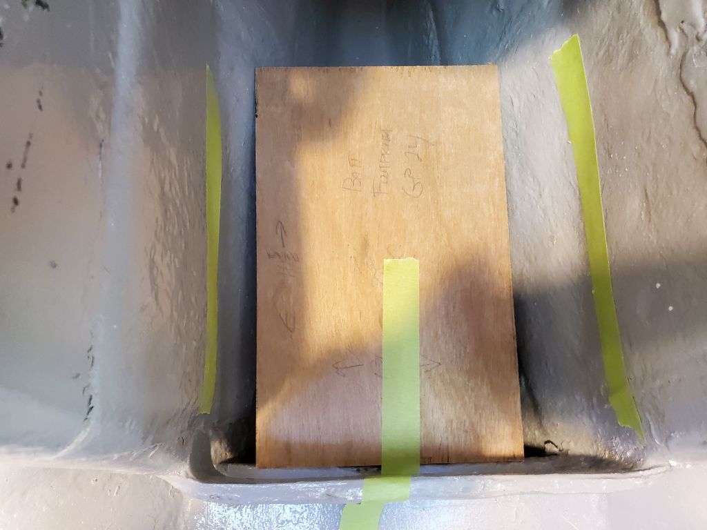
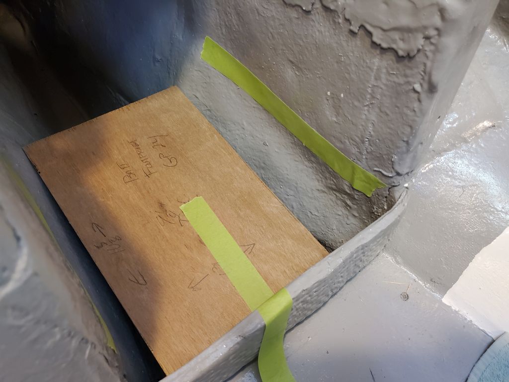
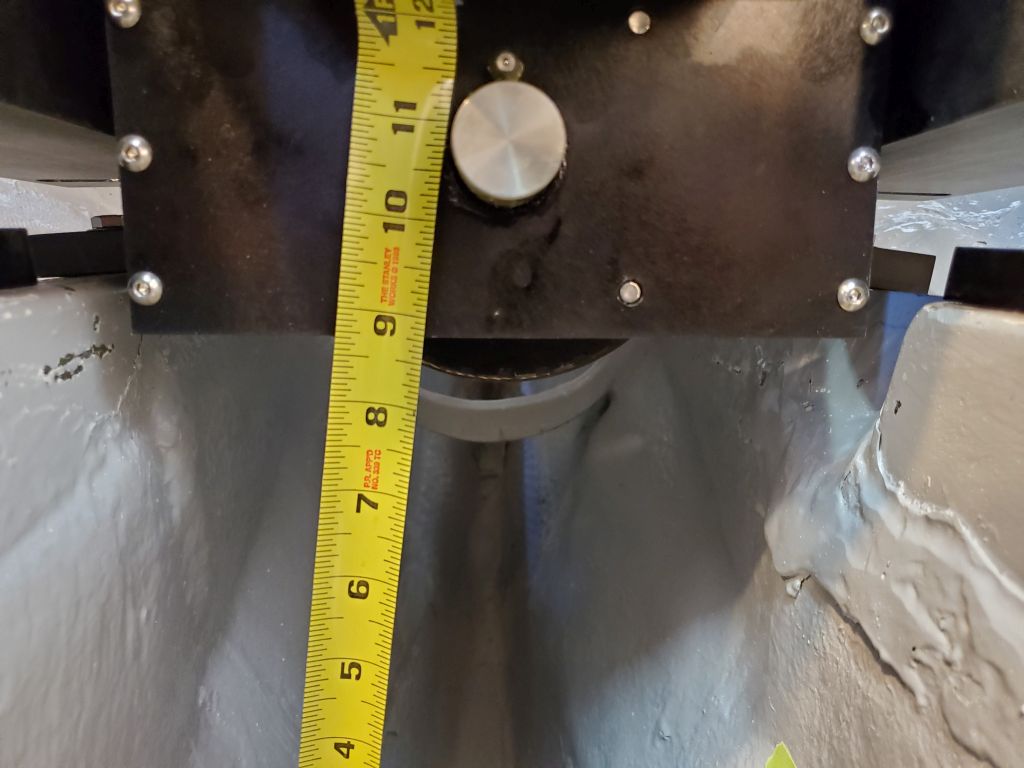
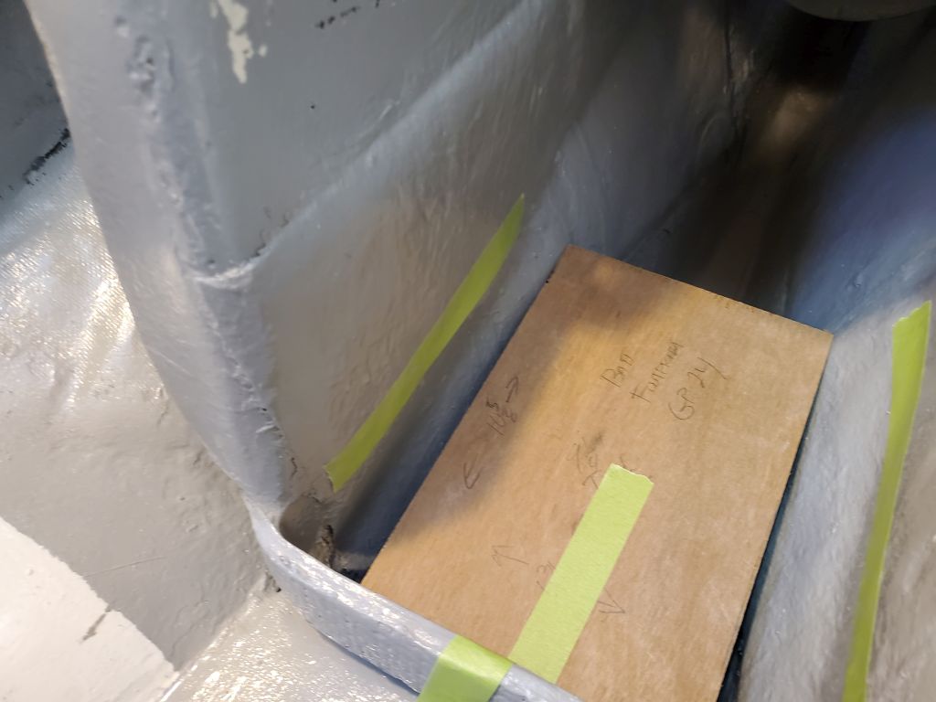
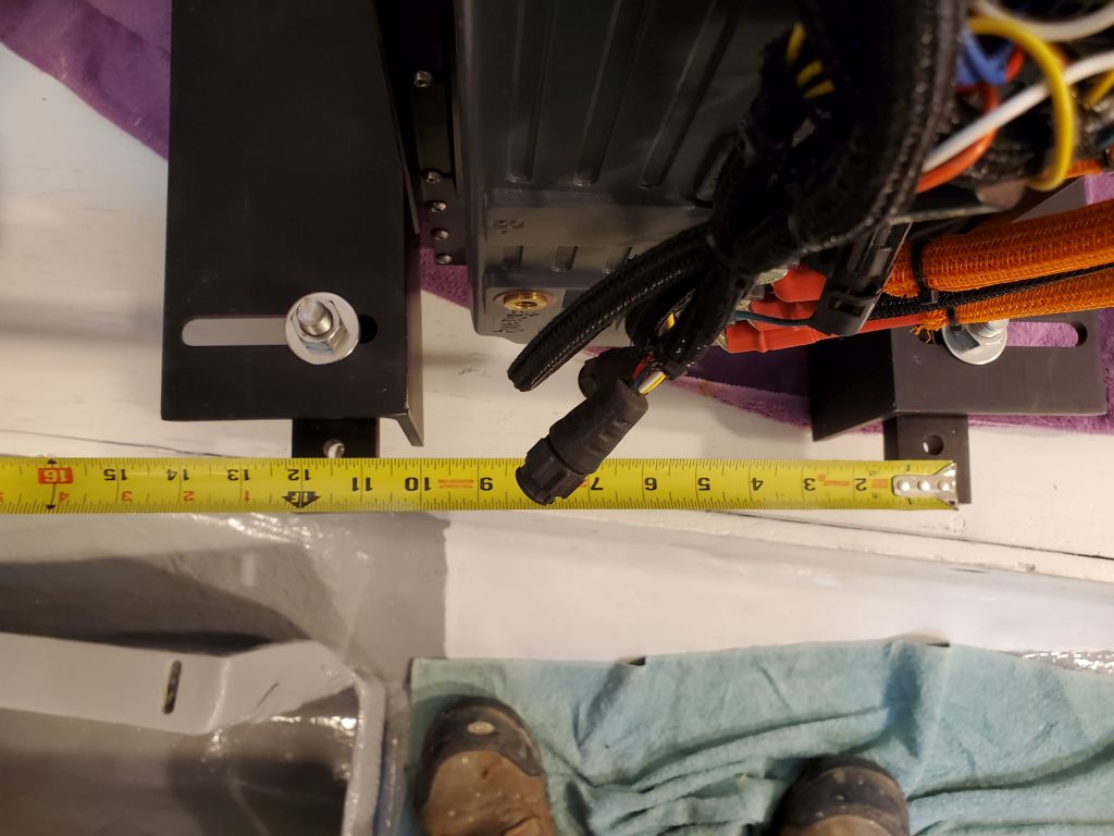
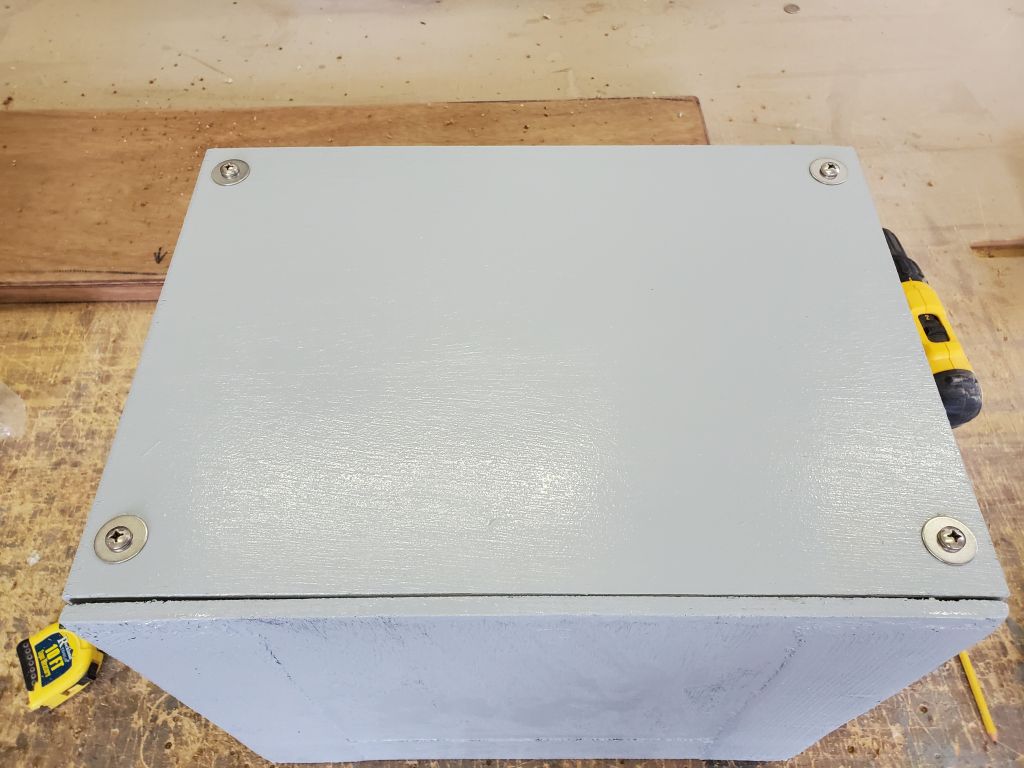
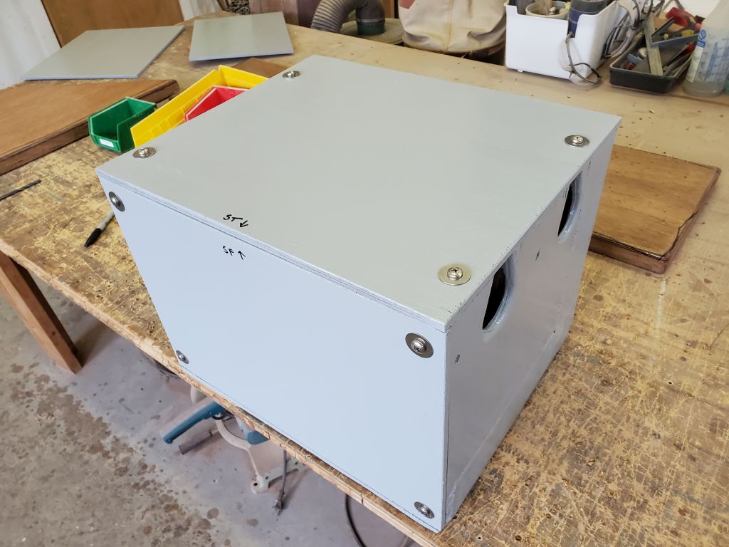
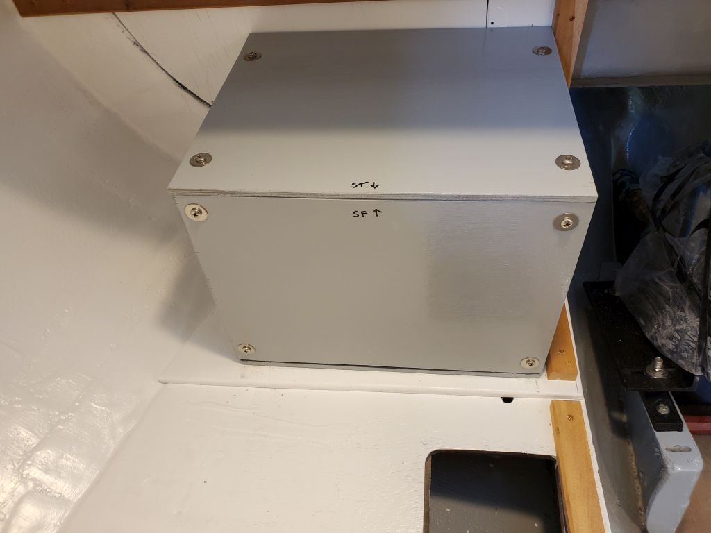
Because the inside dimensions of the boxes were slightly larger than the batteries, there was a bit of room within, and to help hold the batteries securely I cut and installed some plywood spacers to fill the gaps.  Afterwards, I installed the fronts more or less permanently, and, for protection, installed the tops as well, though wiring was still to come.  To that end, I made some rough measurements so I could order the necessary cable and have it on hand for the coming week.

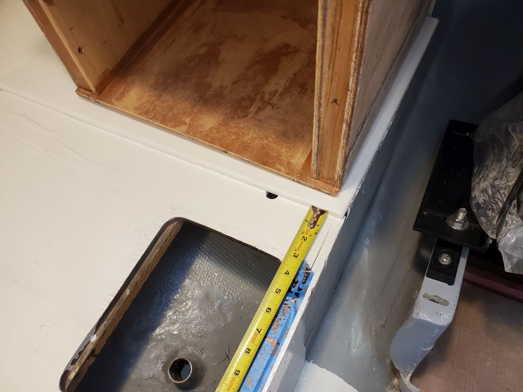
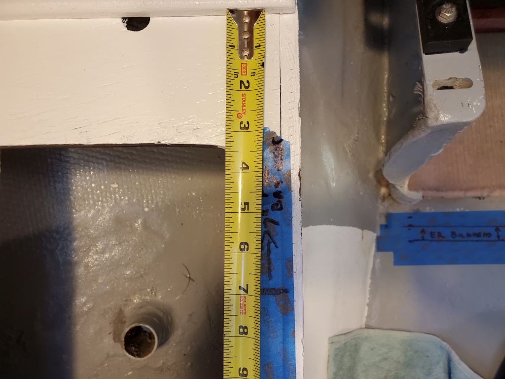
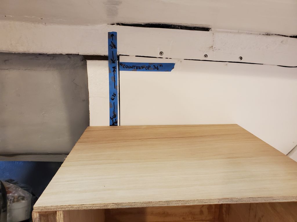
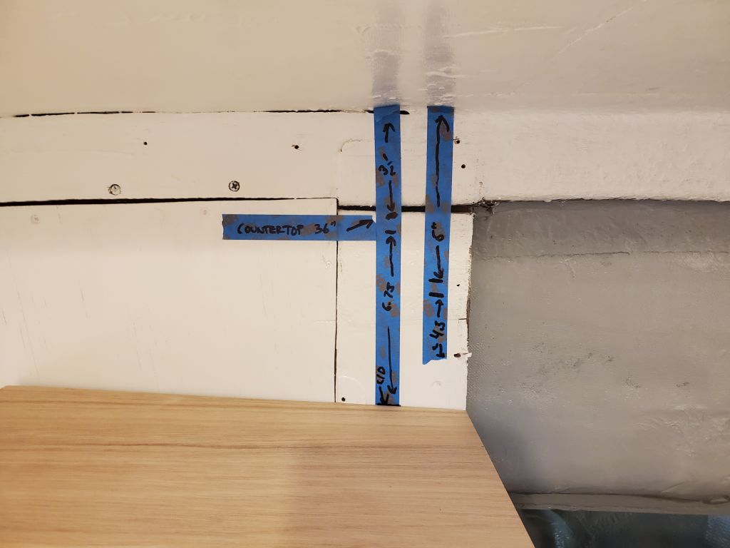
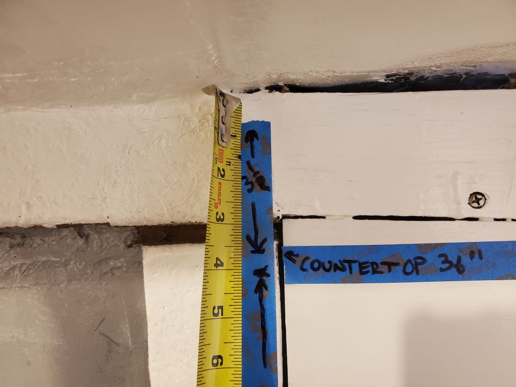
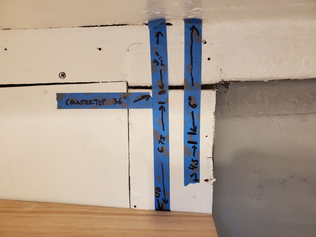
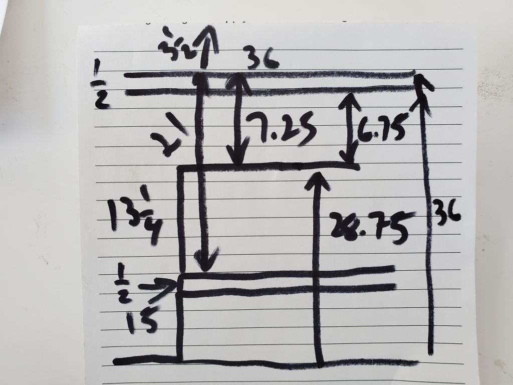
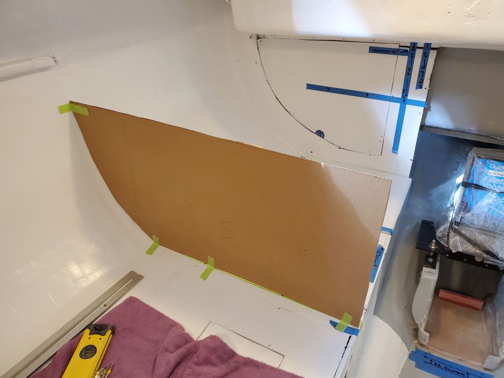
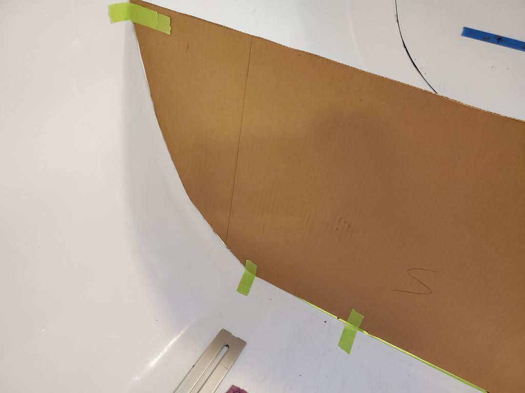
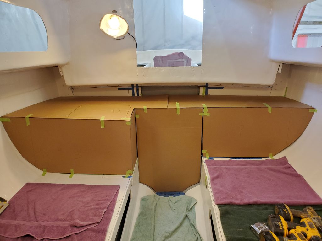
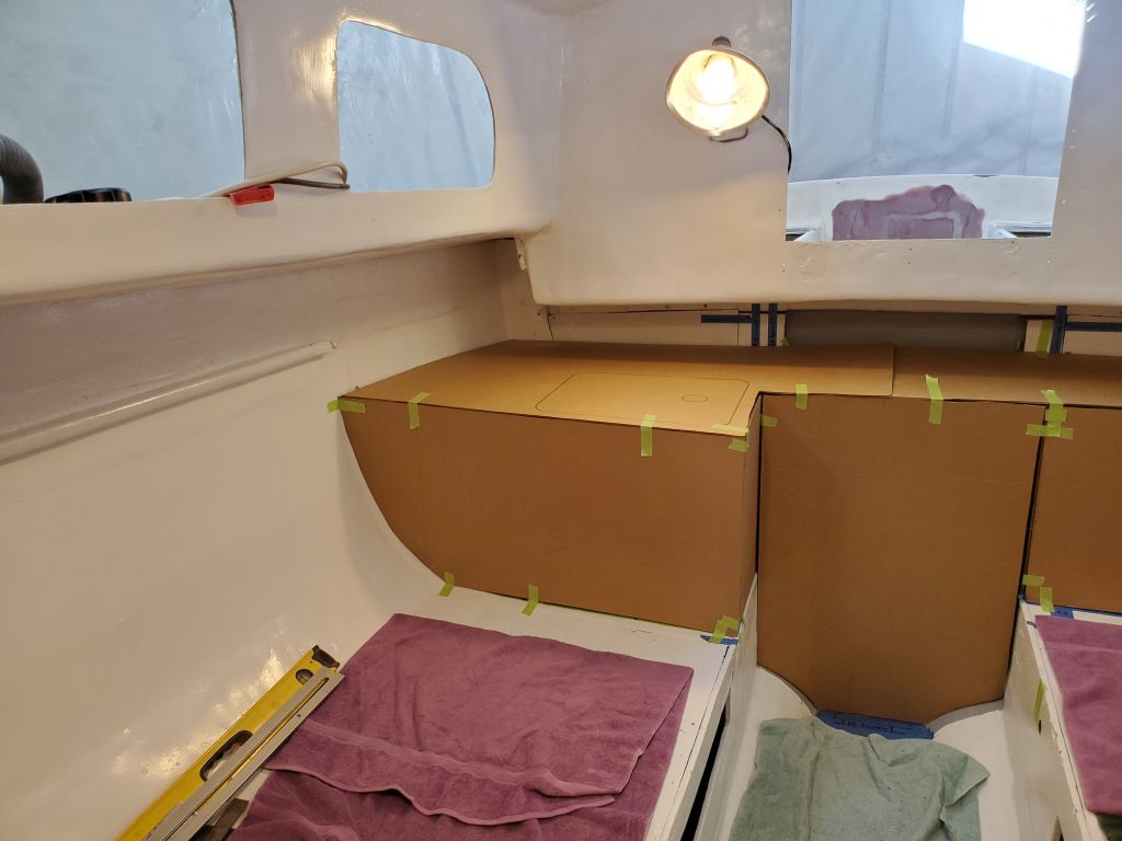
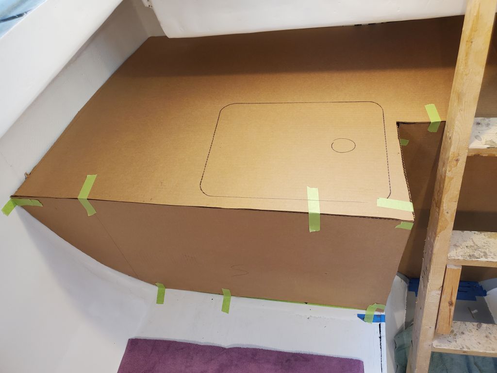
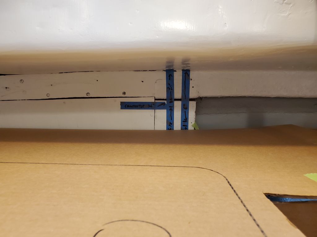
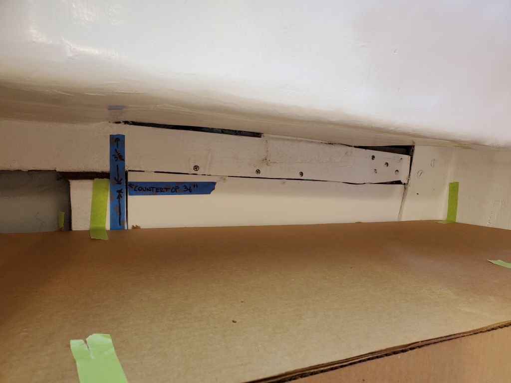
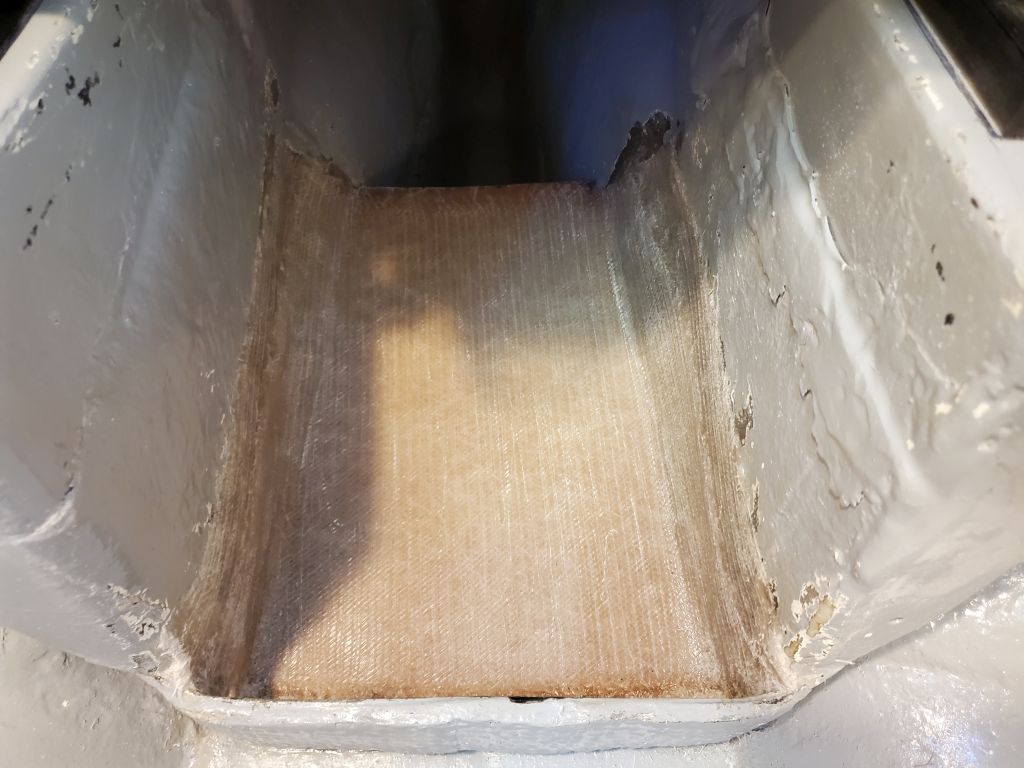
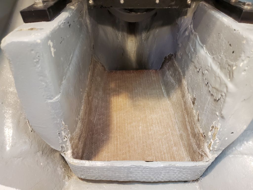
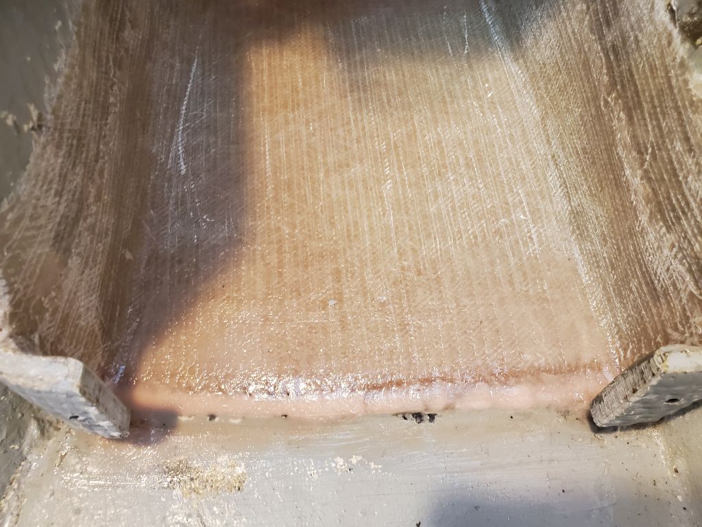
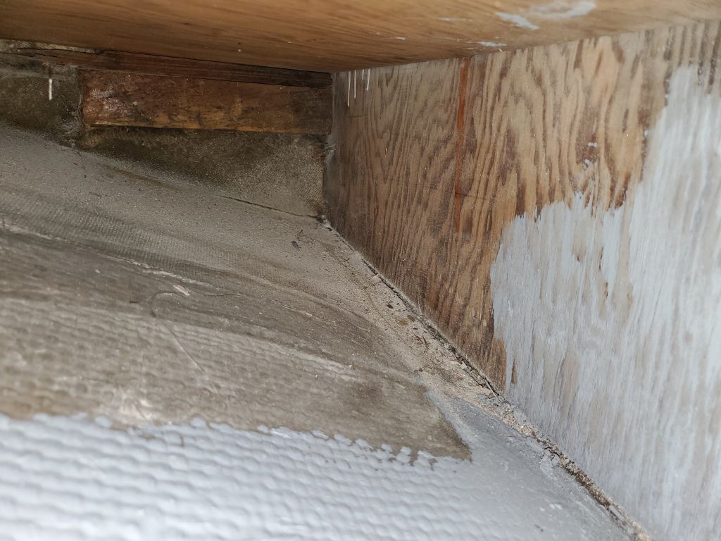
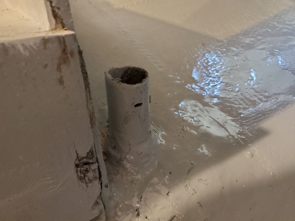
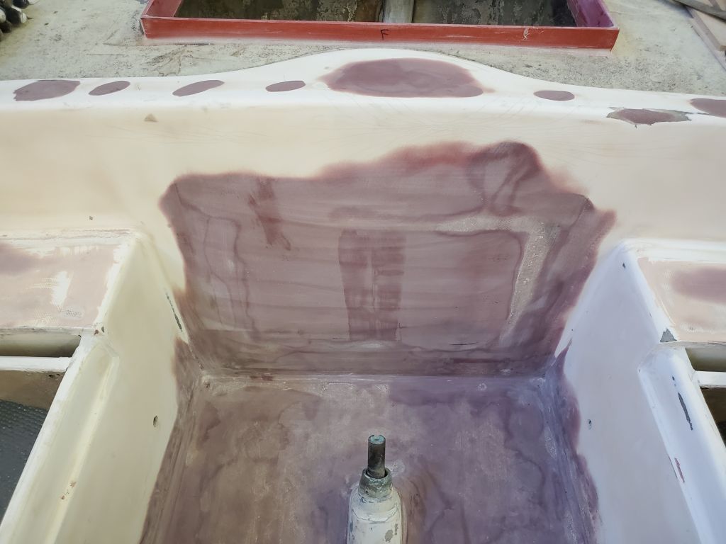
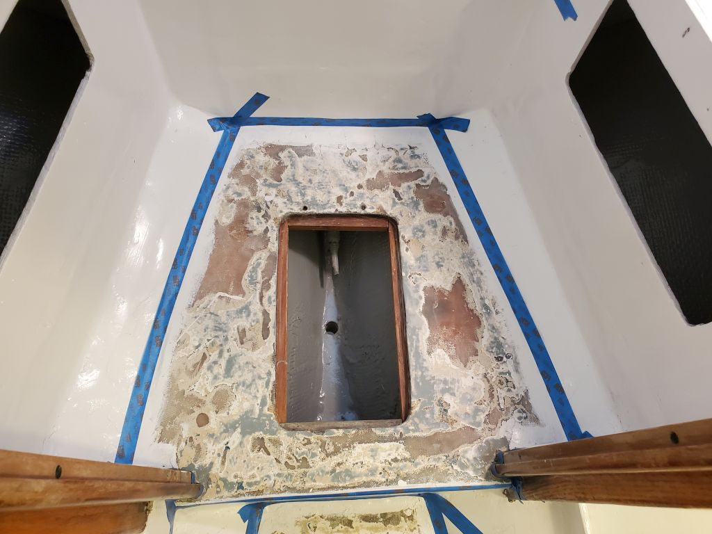
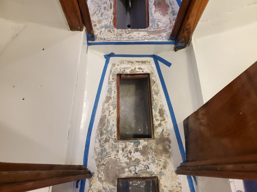
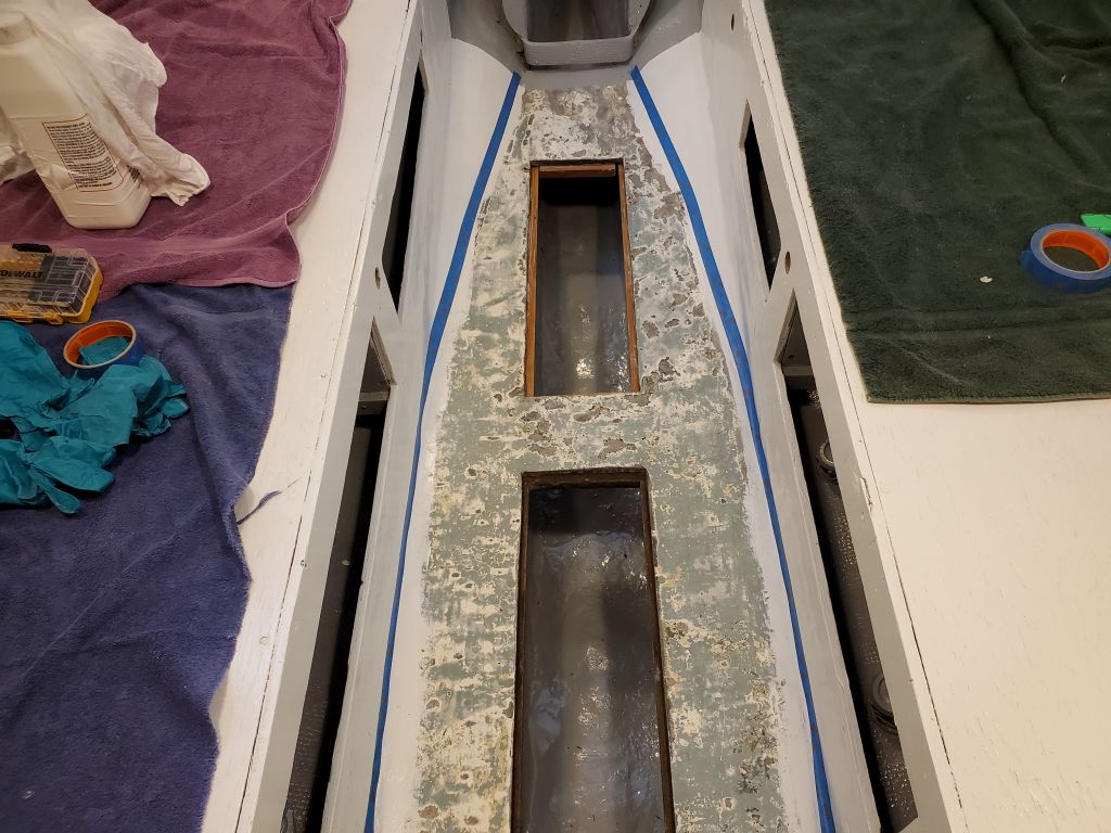
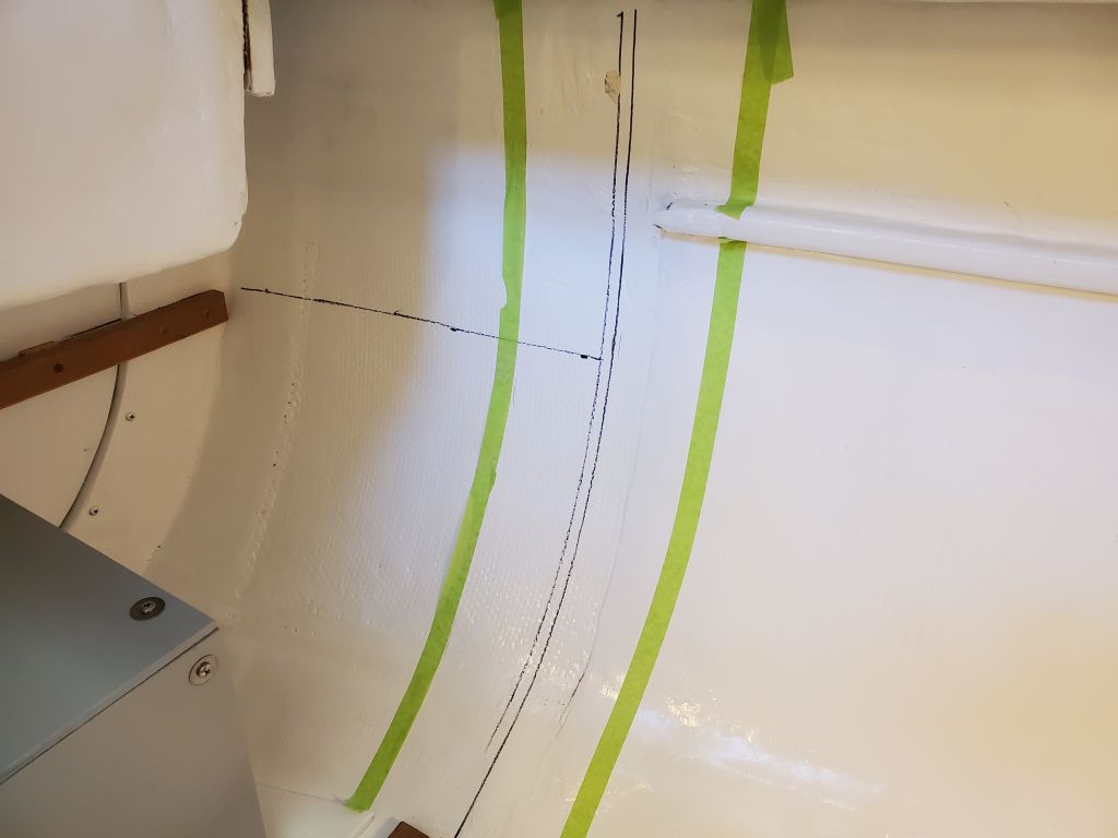
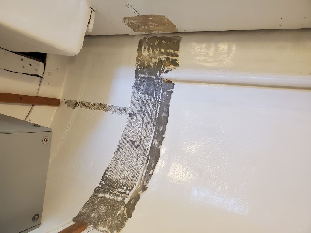
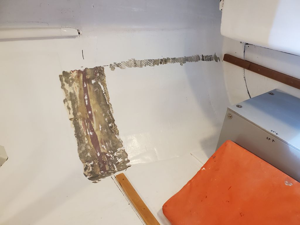
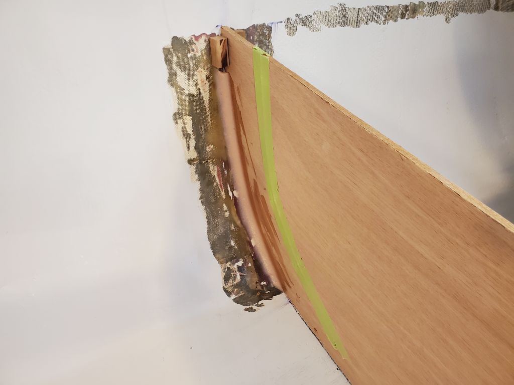
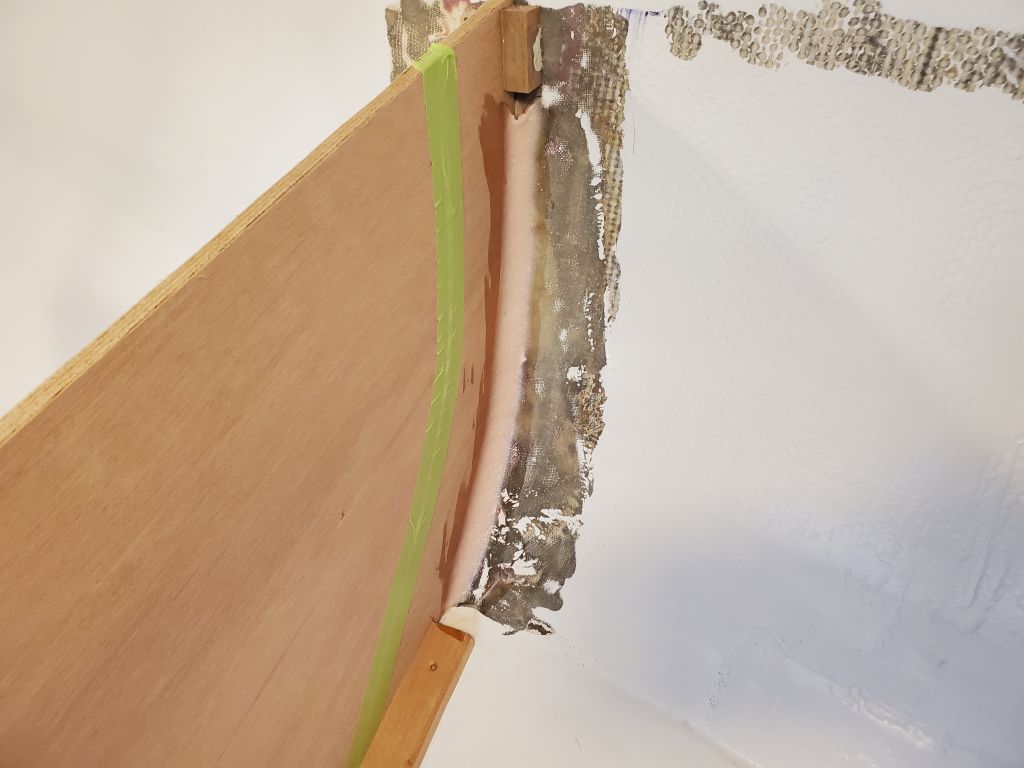
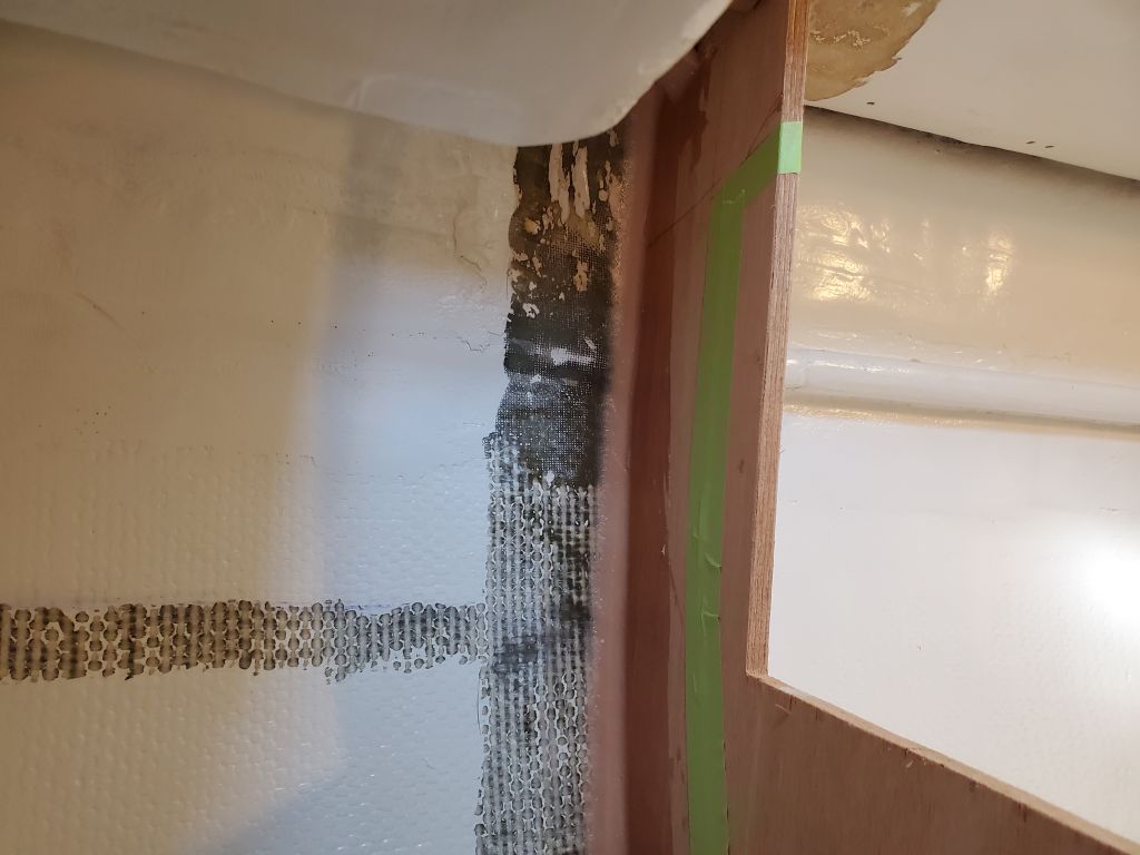
Now that the batteries were in place, I could move ahead with the final installation of the galley parts, at least what was prepared so far.  At each bulkhead location, I marked and ground away the paint and other coatings from the hull (and deck, to port) to provide bare laminate for bonding purposes.  I also removed the paint from narrow strips aft of each bulkhead in way of the future countertop location, to allow for some cleats to support the countertops along the hull.  This all made far more of a mess than I would have thought (and did think) possible, but I took the opportunity to do a good cleanup, and also aired out the shop since it was an incredibly nice day near 60°, a real pleasure (if taunting) for March.

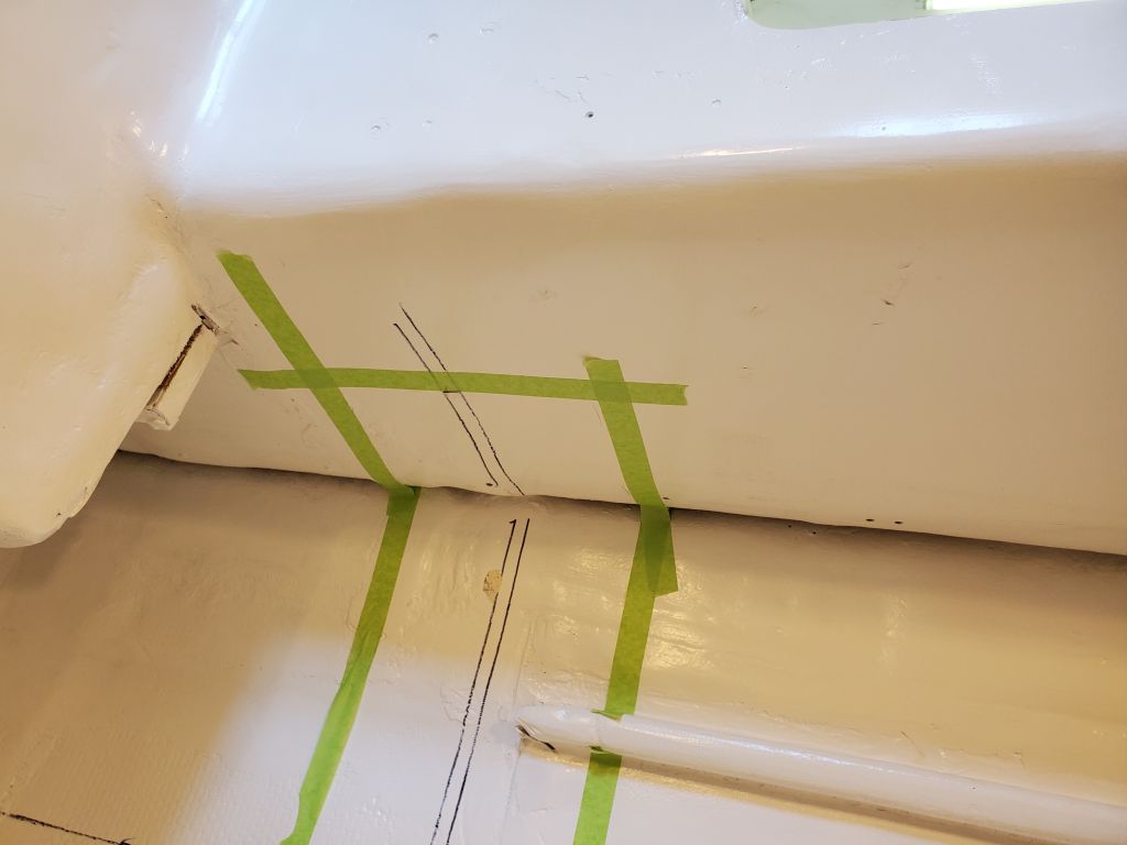
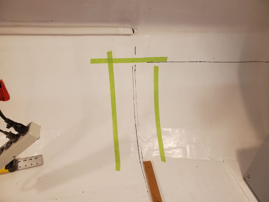
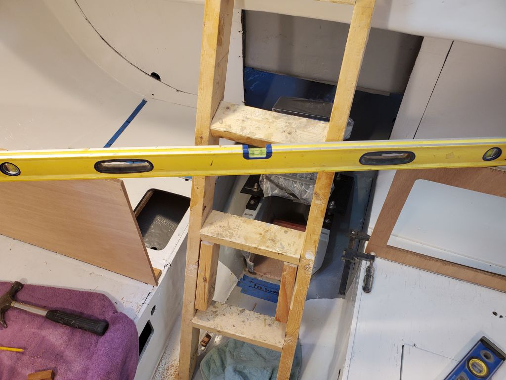
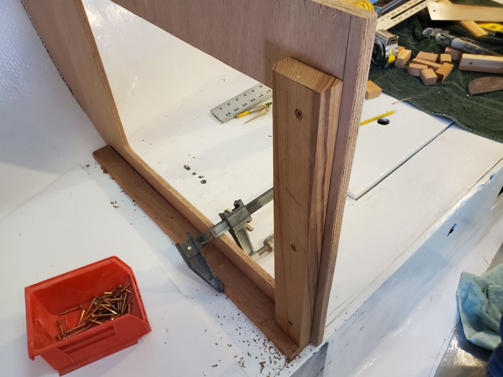
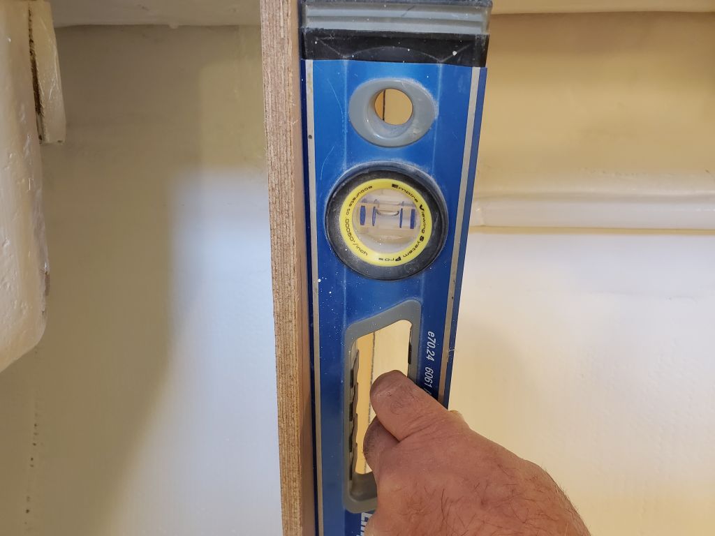
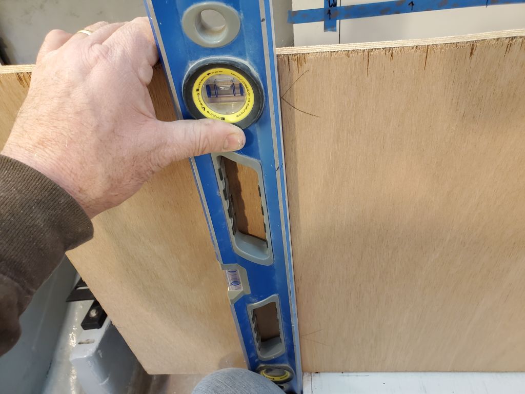
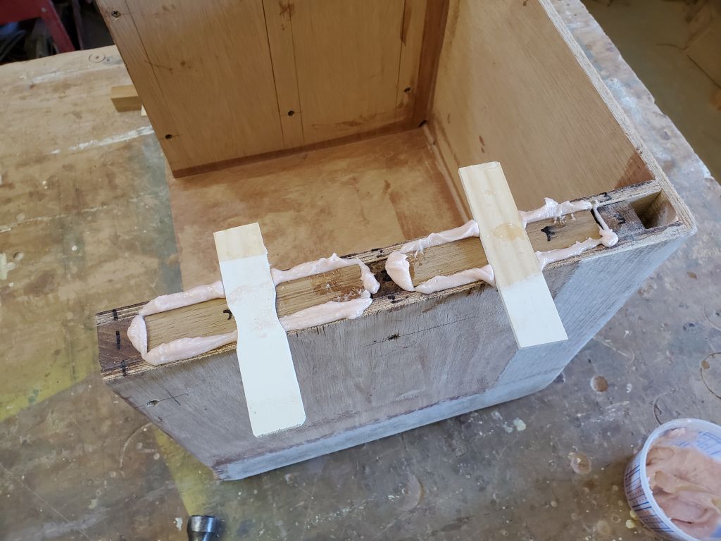
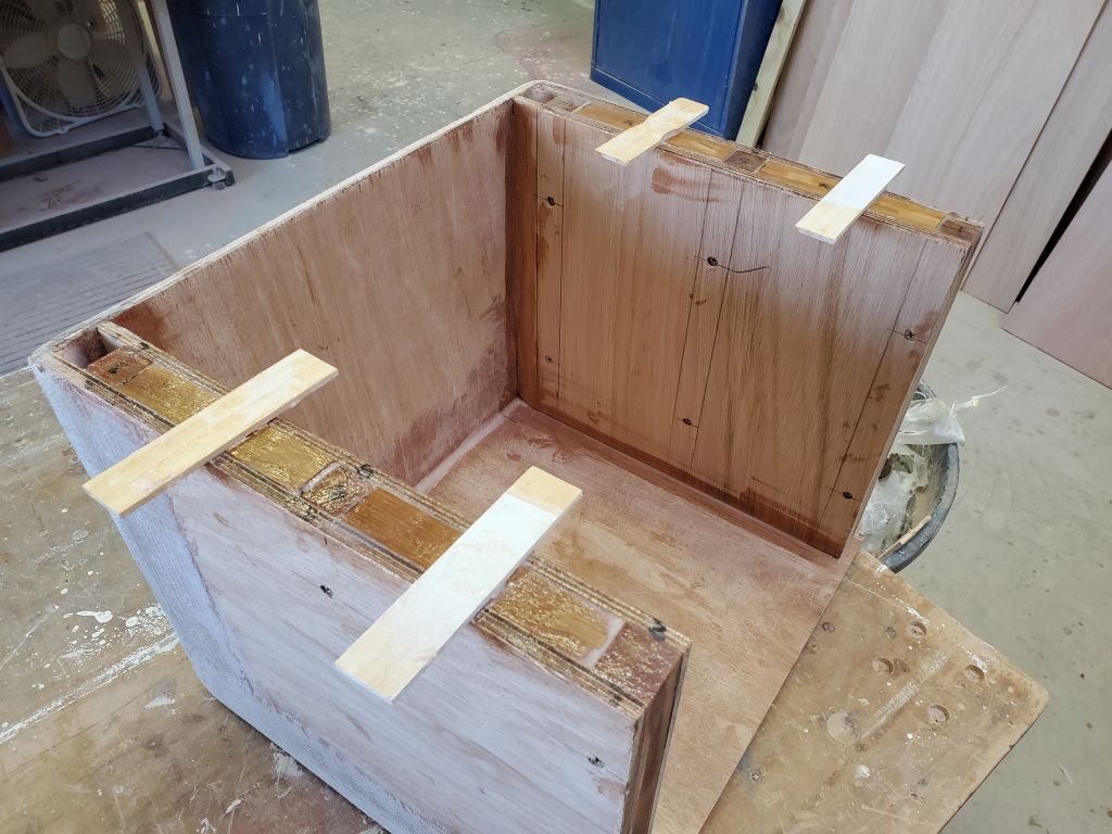
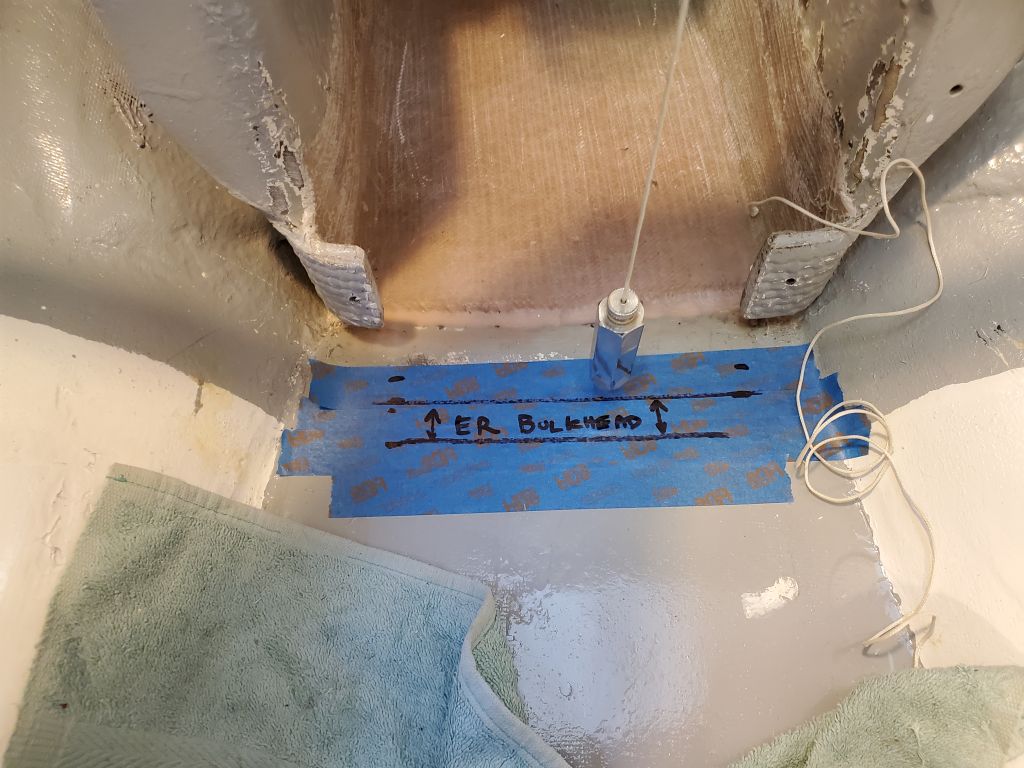
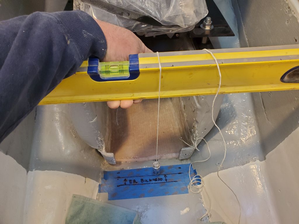
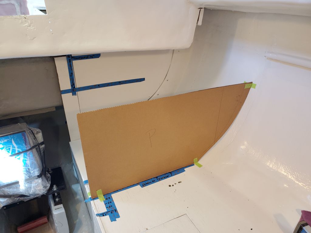
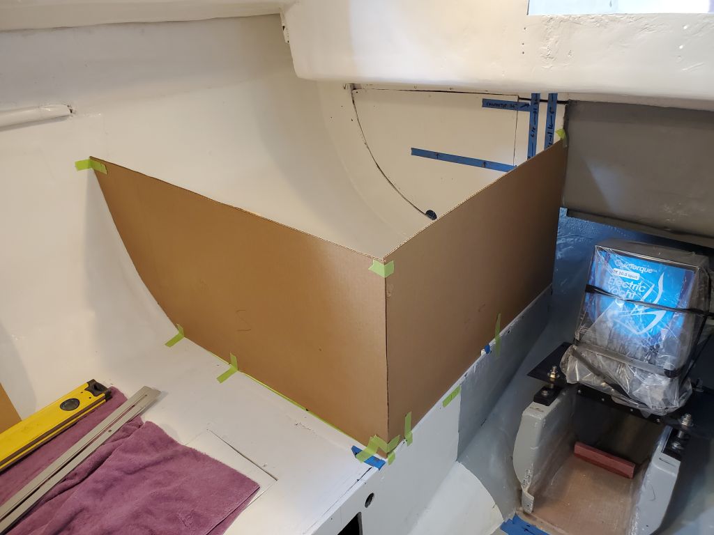
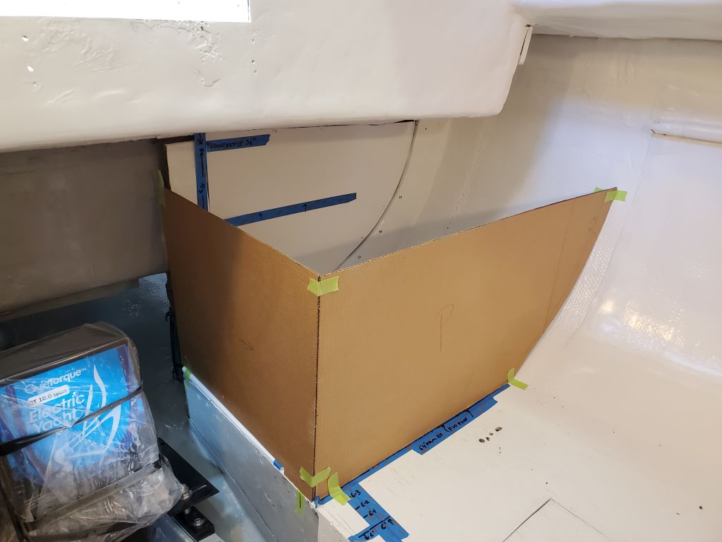
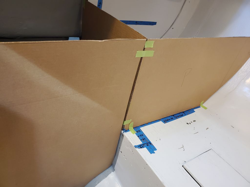
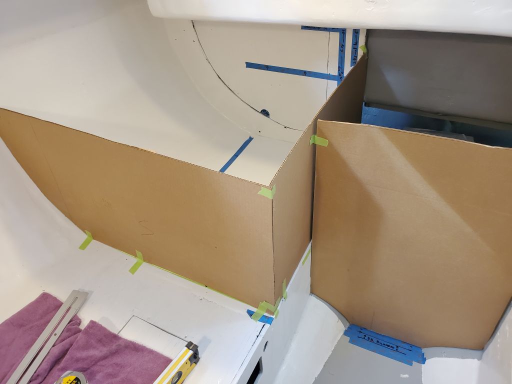
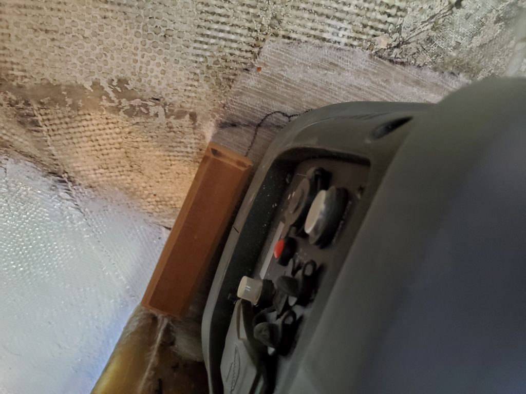
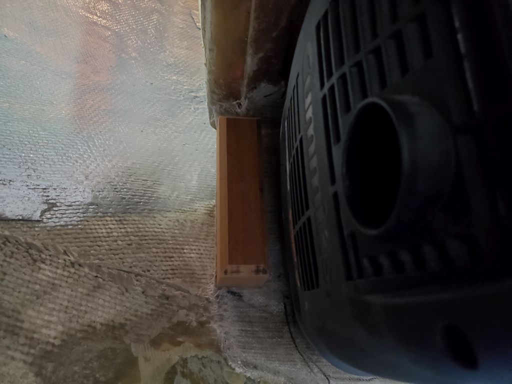
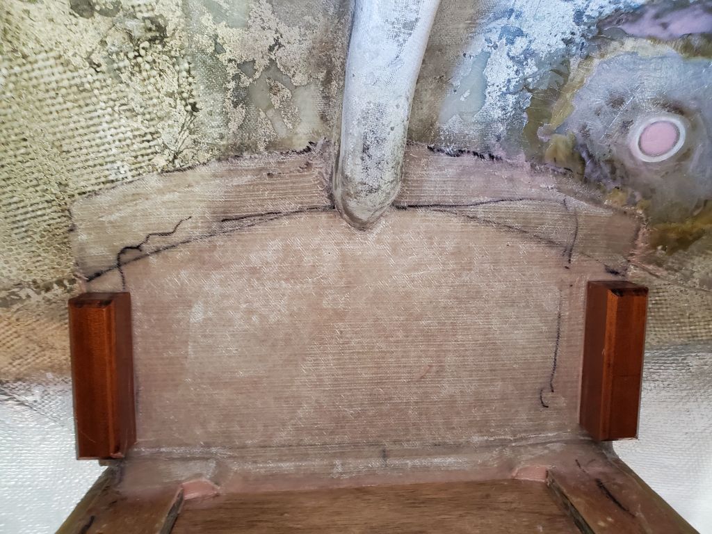
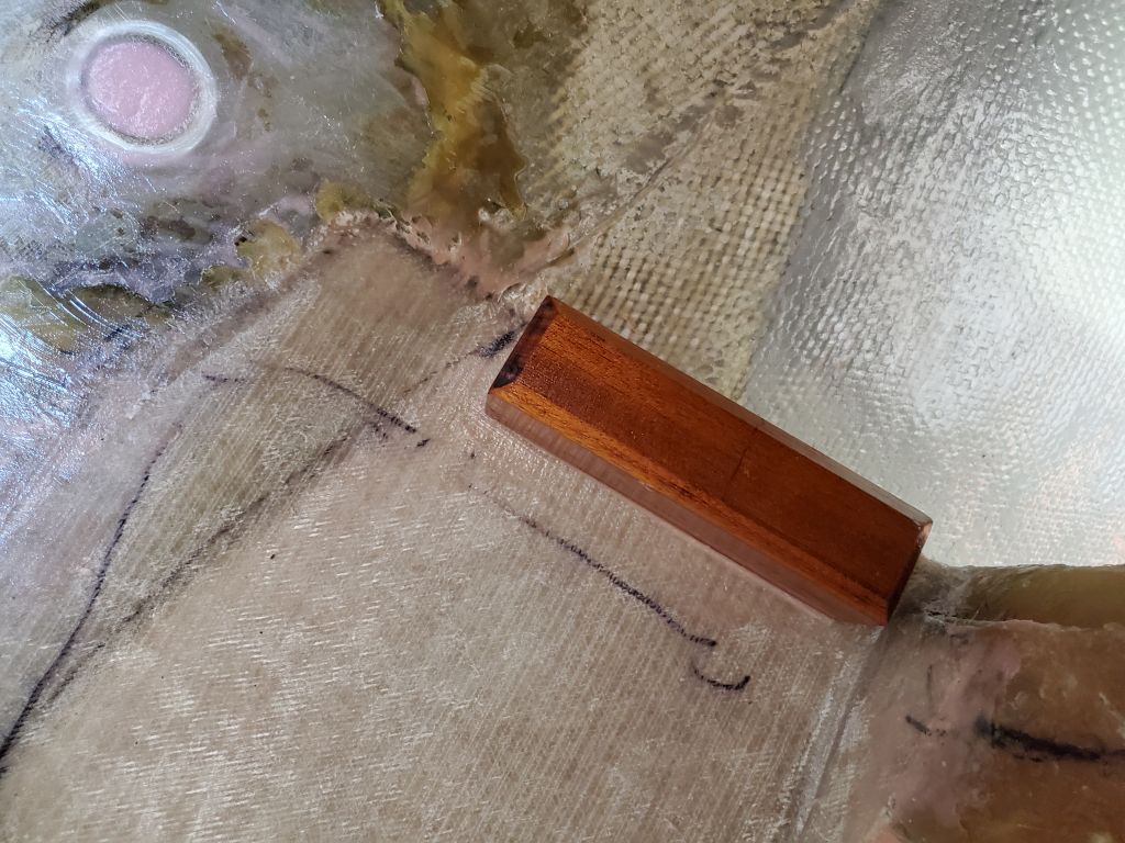
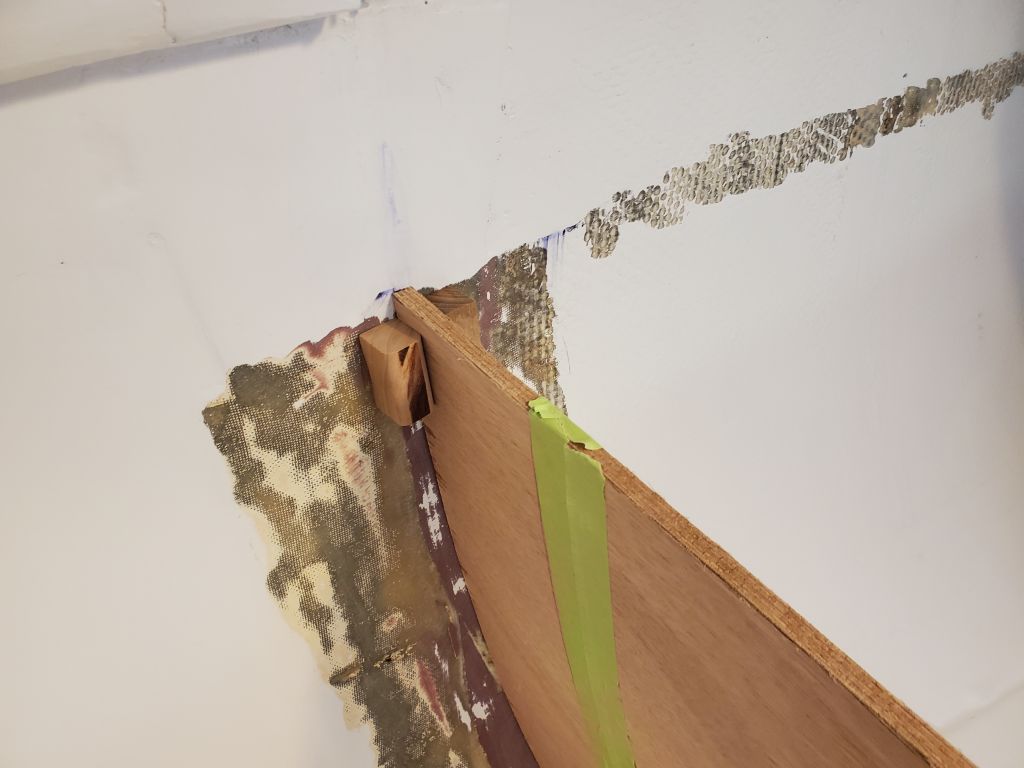
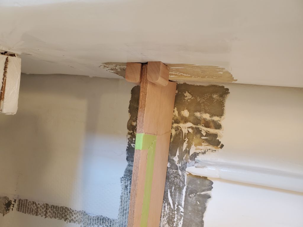
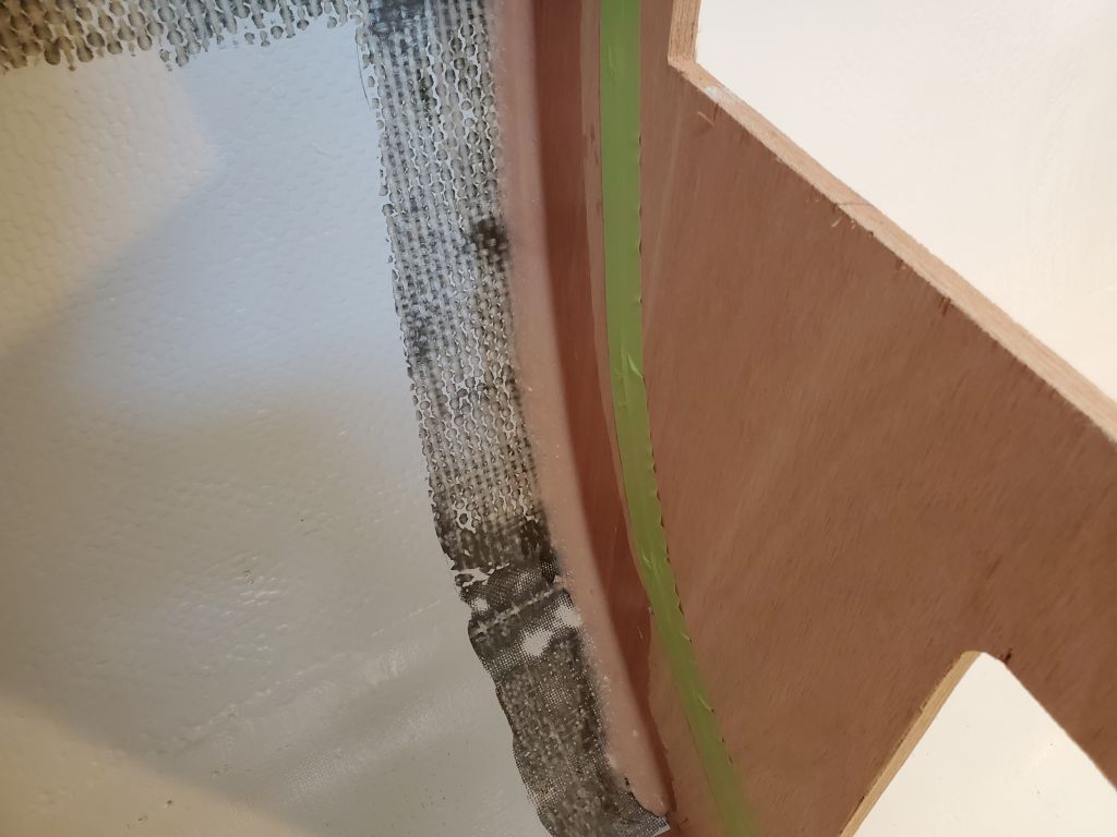
With the surfaces thusly prepared, I completed the first installation step for the two main galley bulkheads, after masking off the bulkheads in preparation for tabbing.  To hold the bulkheads securely in place while being installed, I used small glue blocks as needed to hold each bulkhead plumb and in the right position, and after these preparations epoxy-coated the plywood edge and installed the bulkheads with screws along the settee cleats, and epoxy fillets where they met the hull and deck, leaving this to cure overnight.

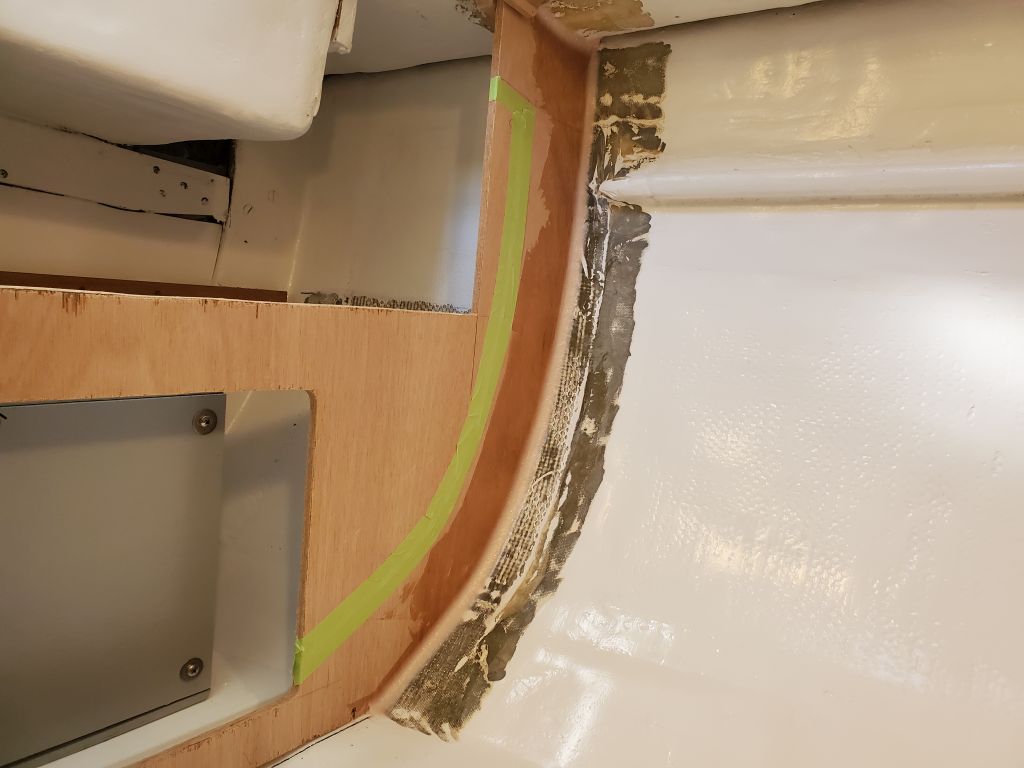
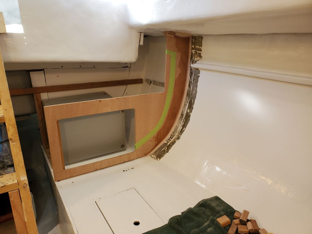
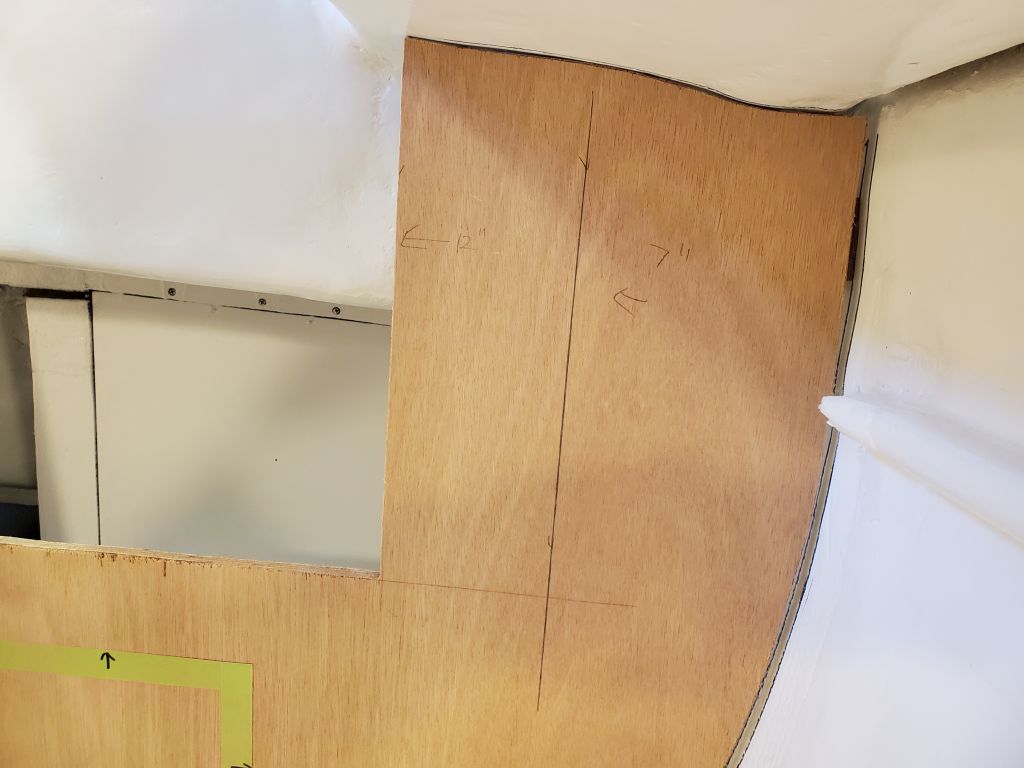
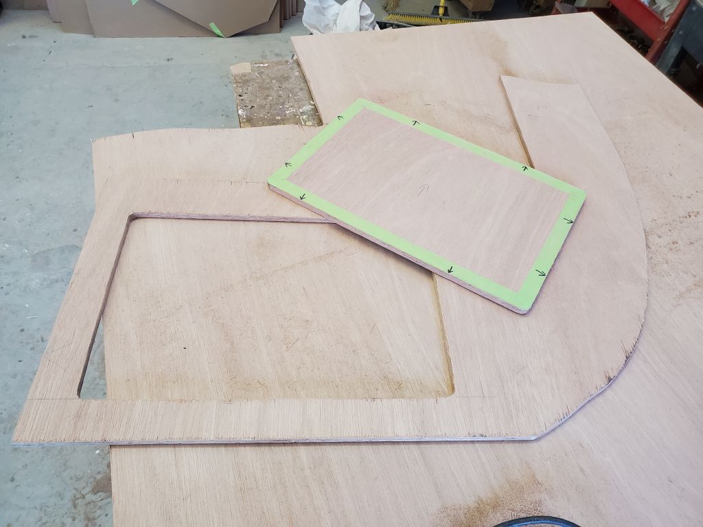
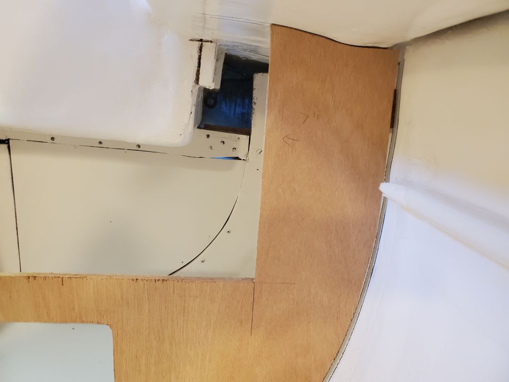
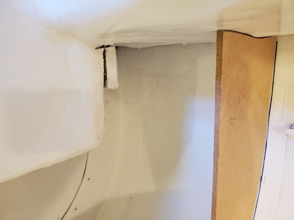
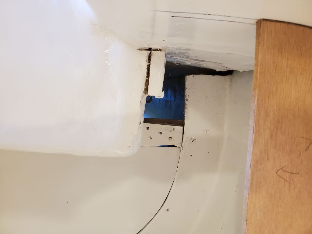
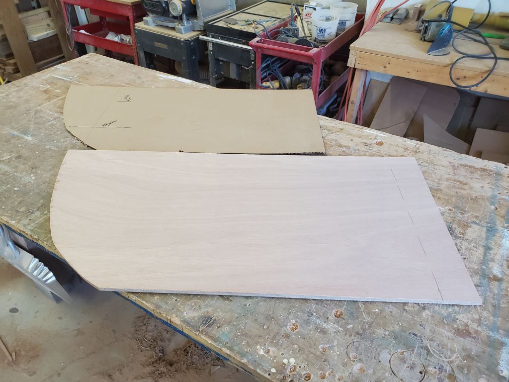
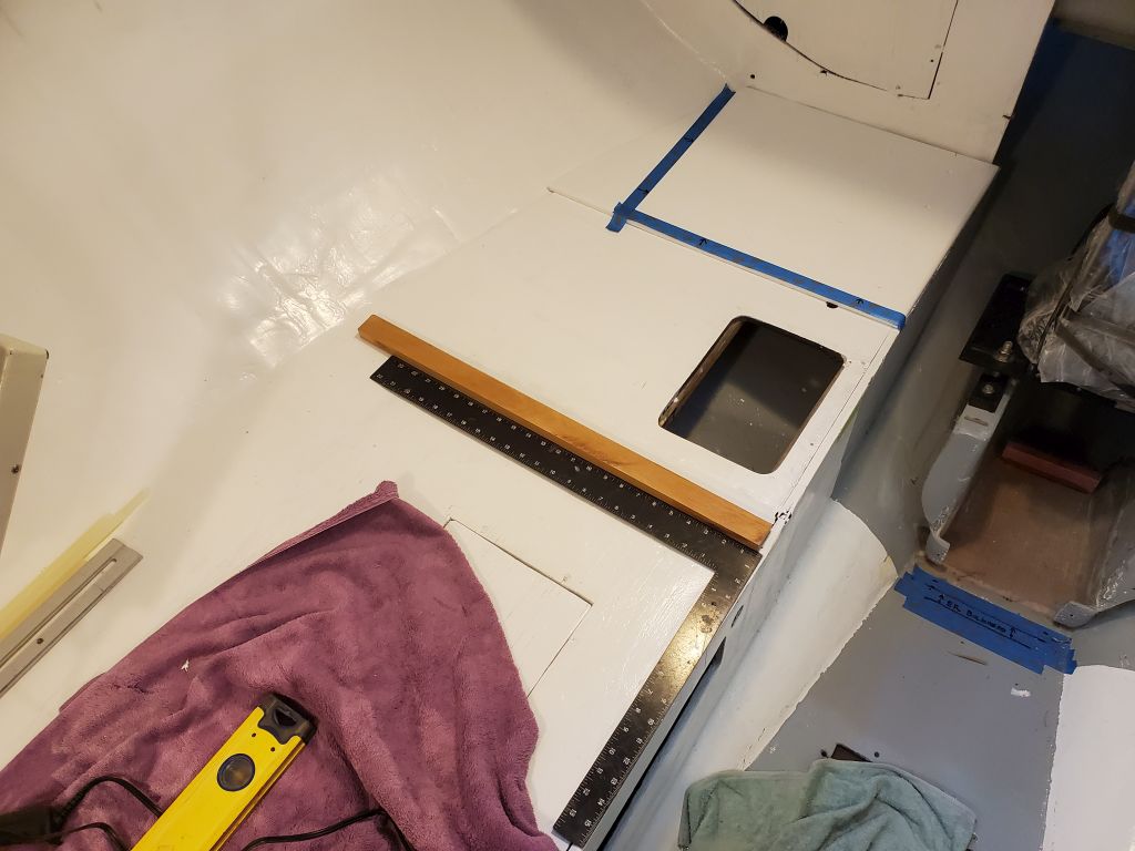
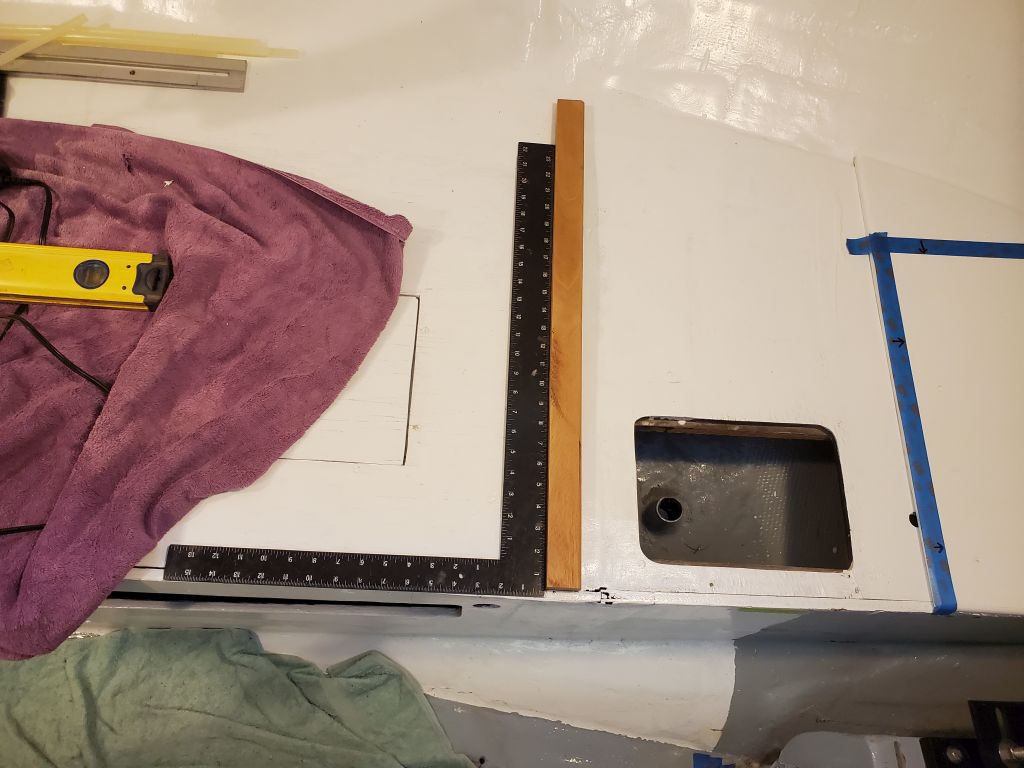
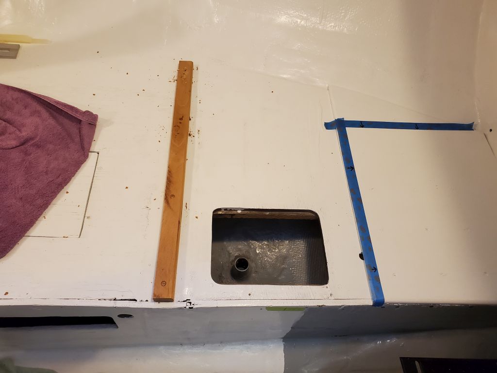
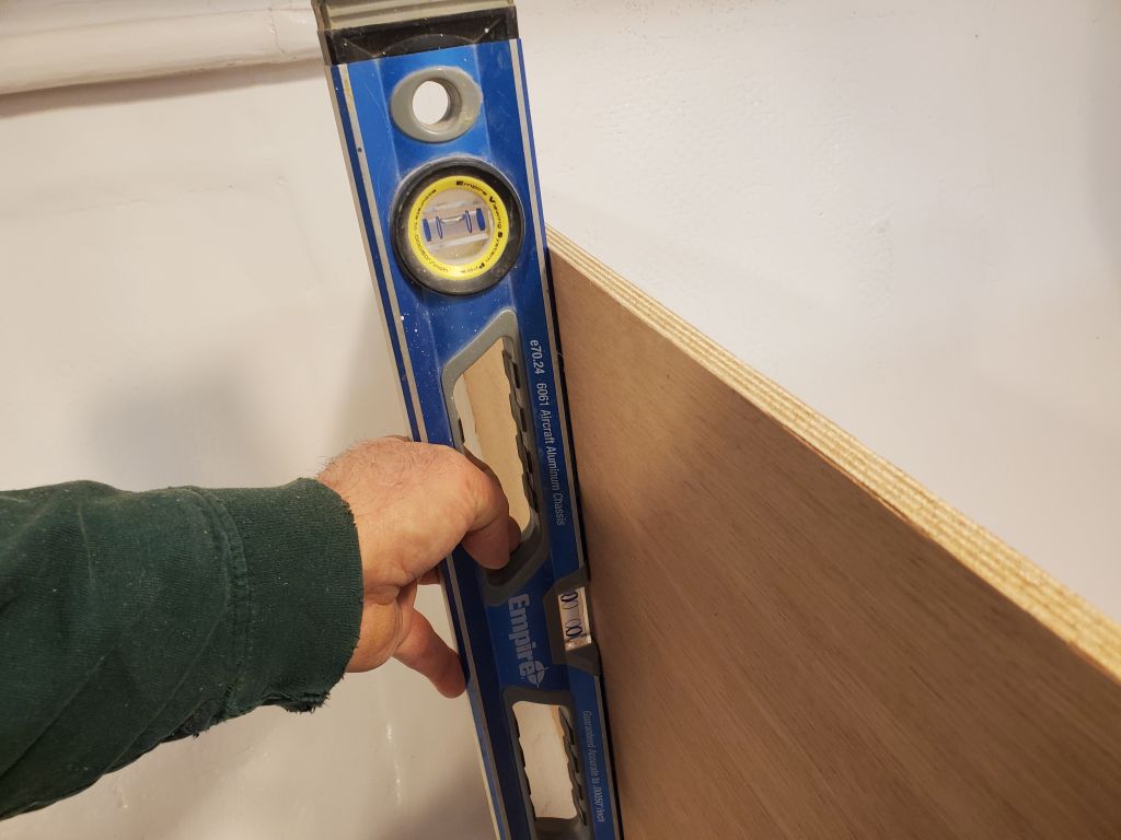
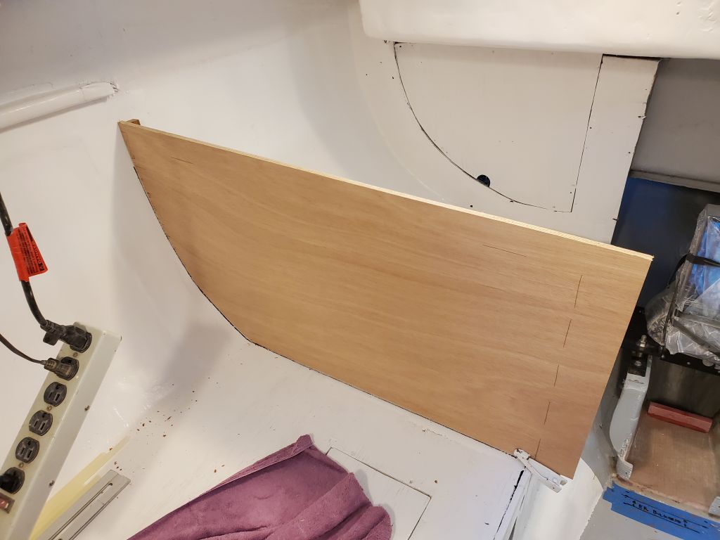
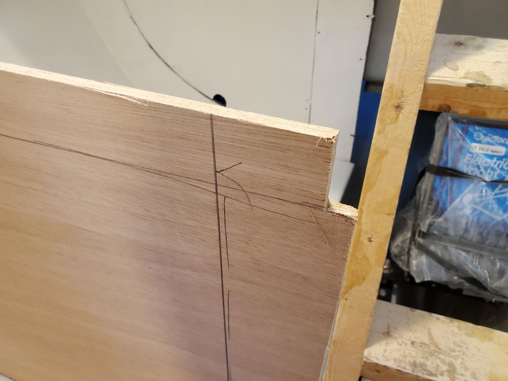
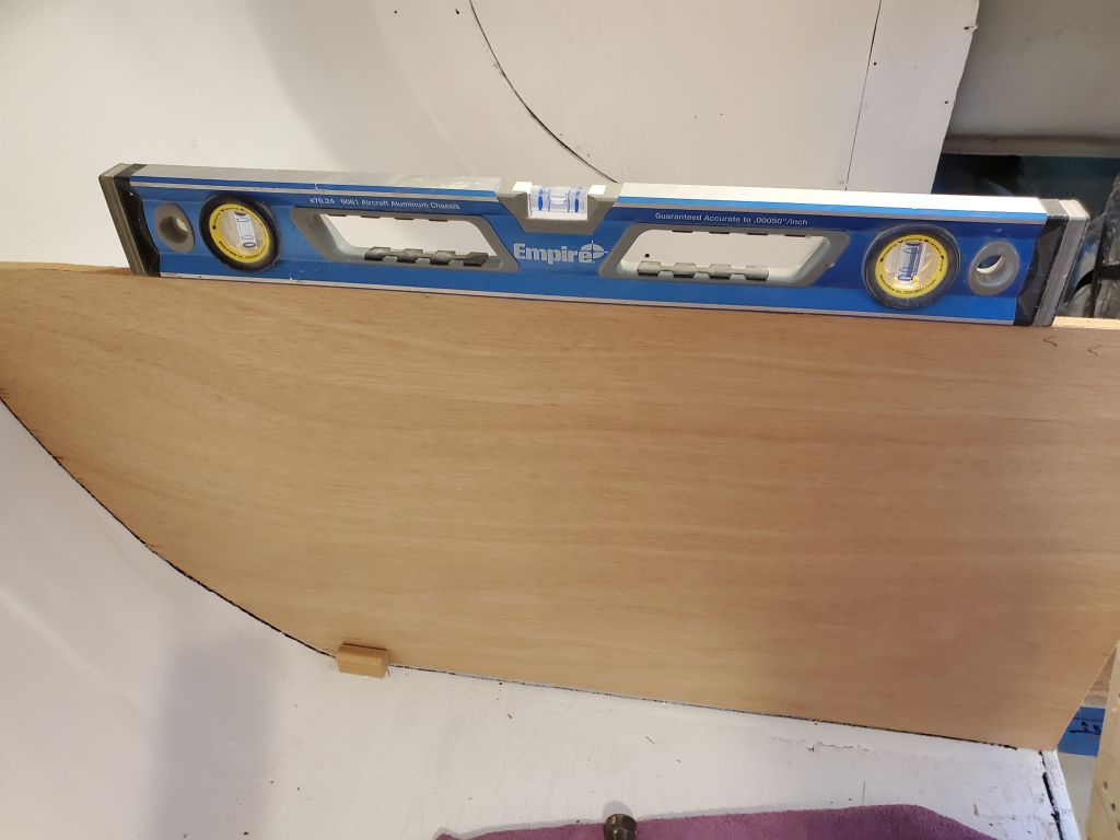
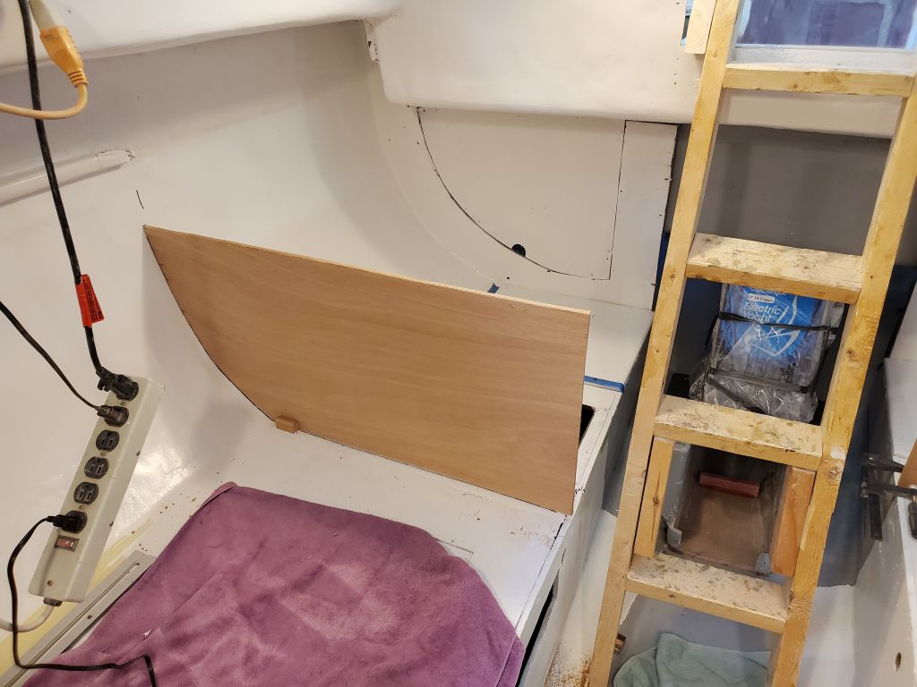
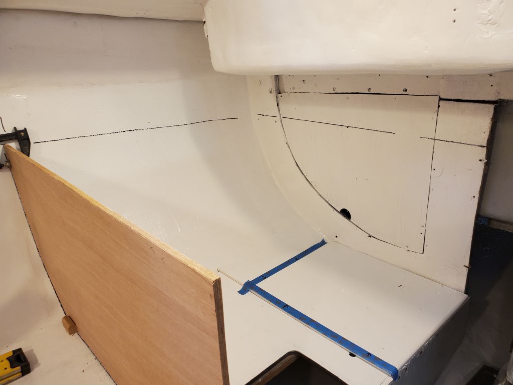
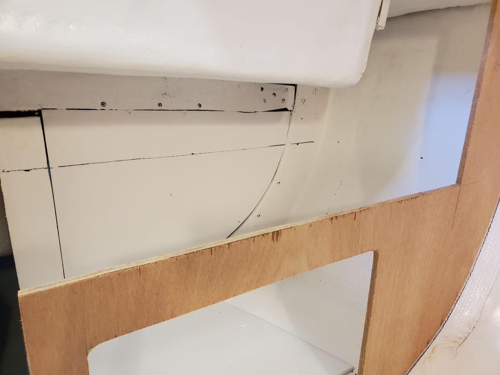
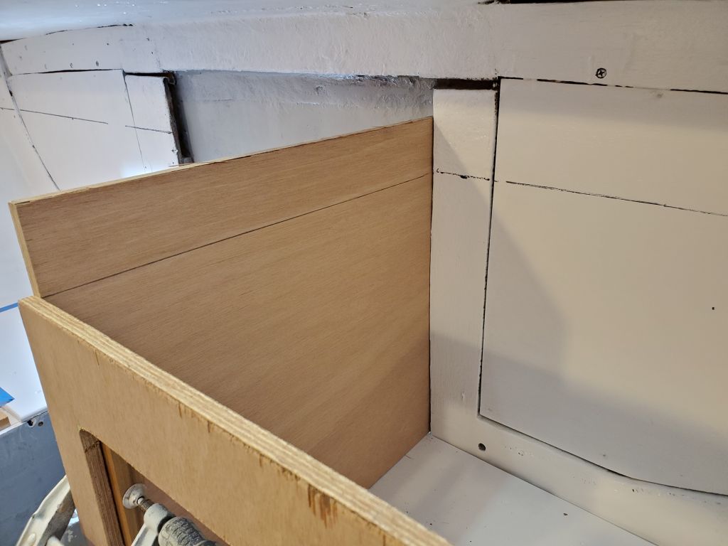
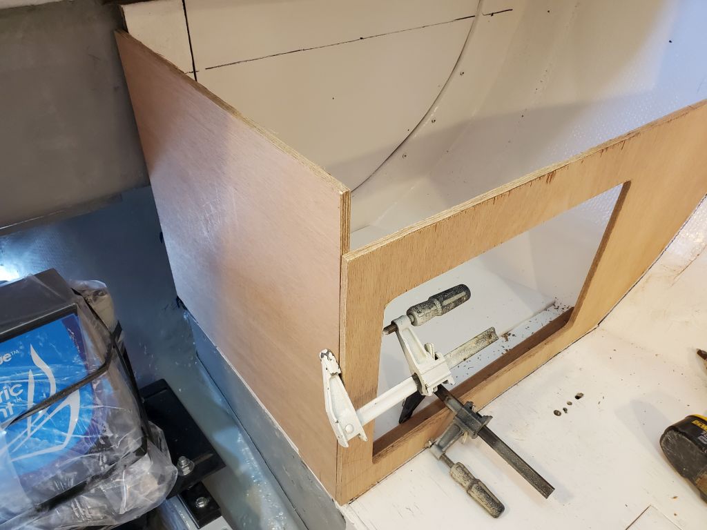
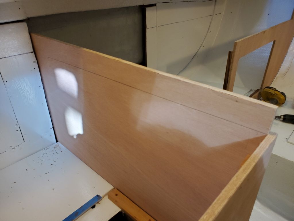
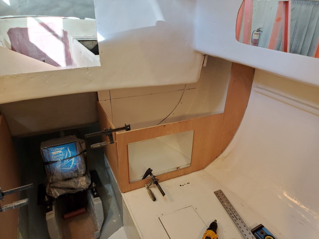
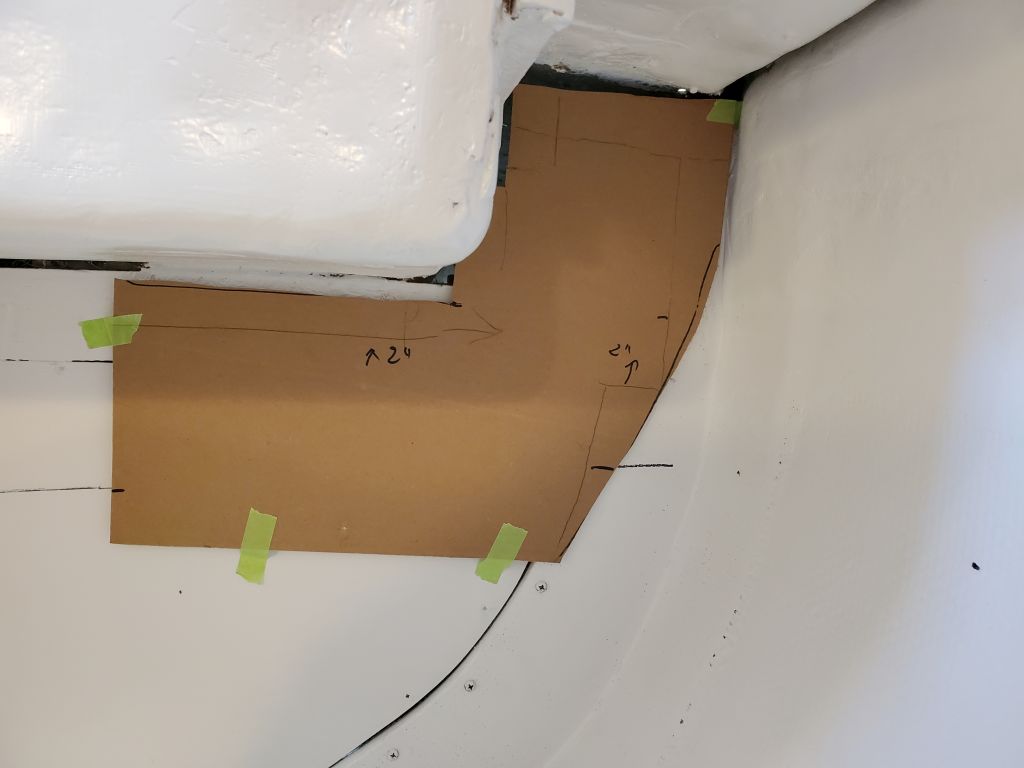
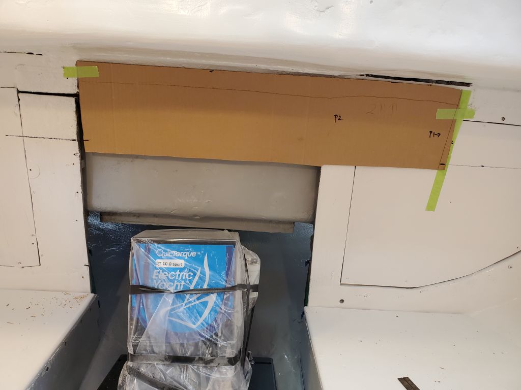
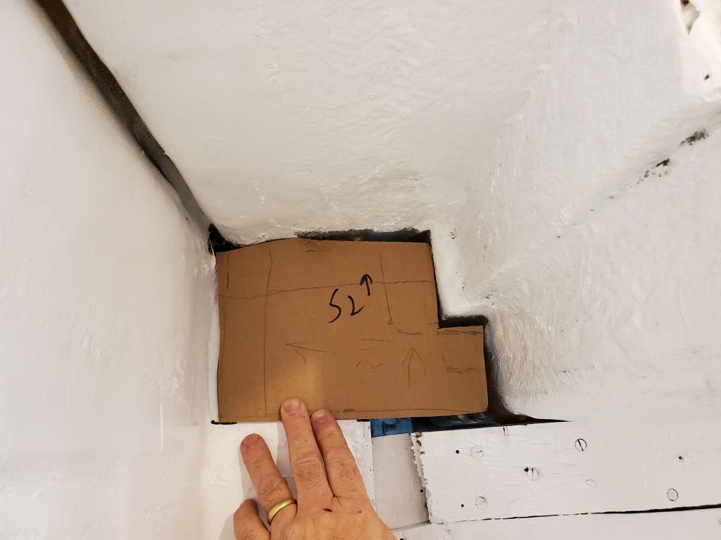
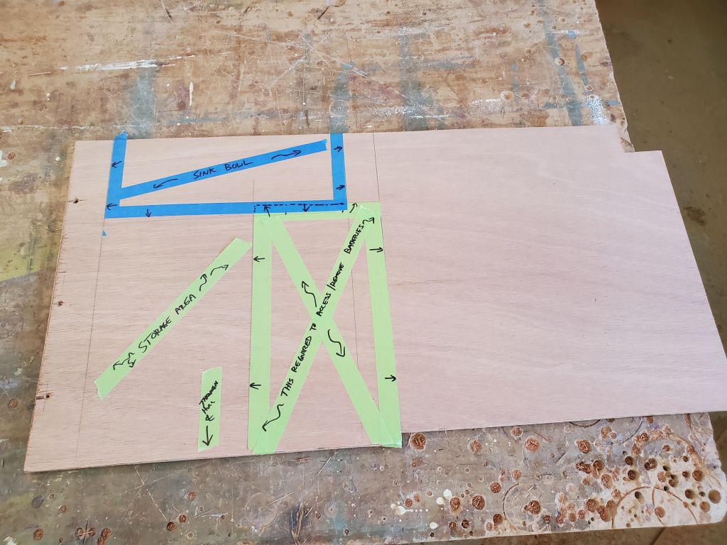
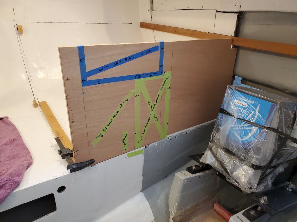
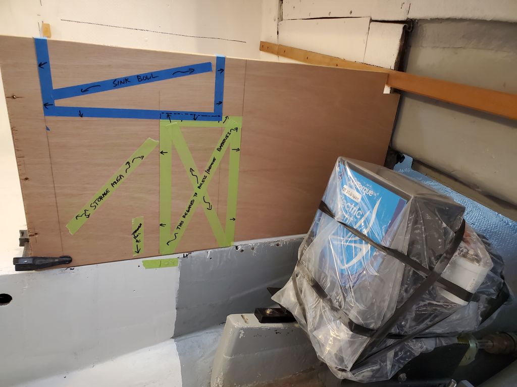
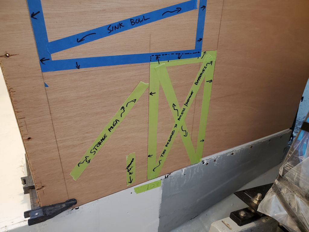
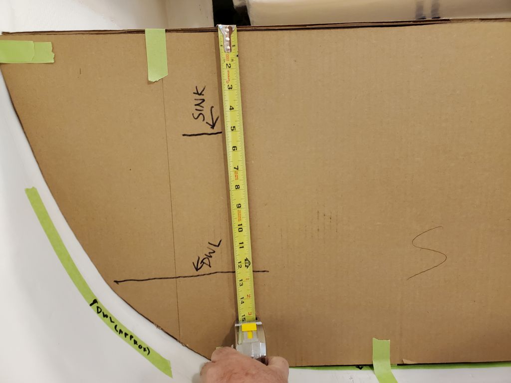
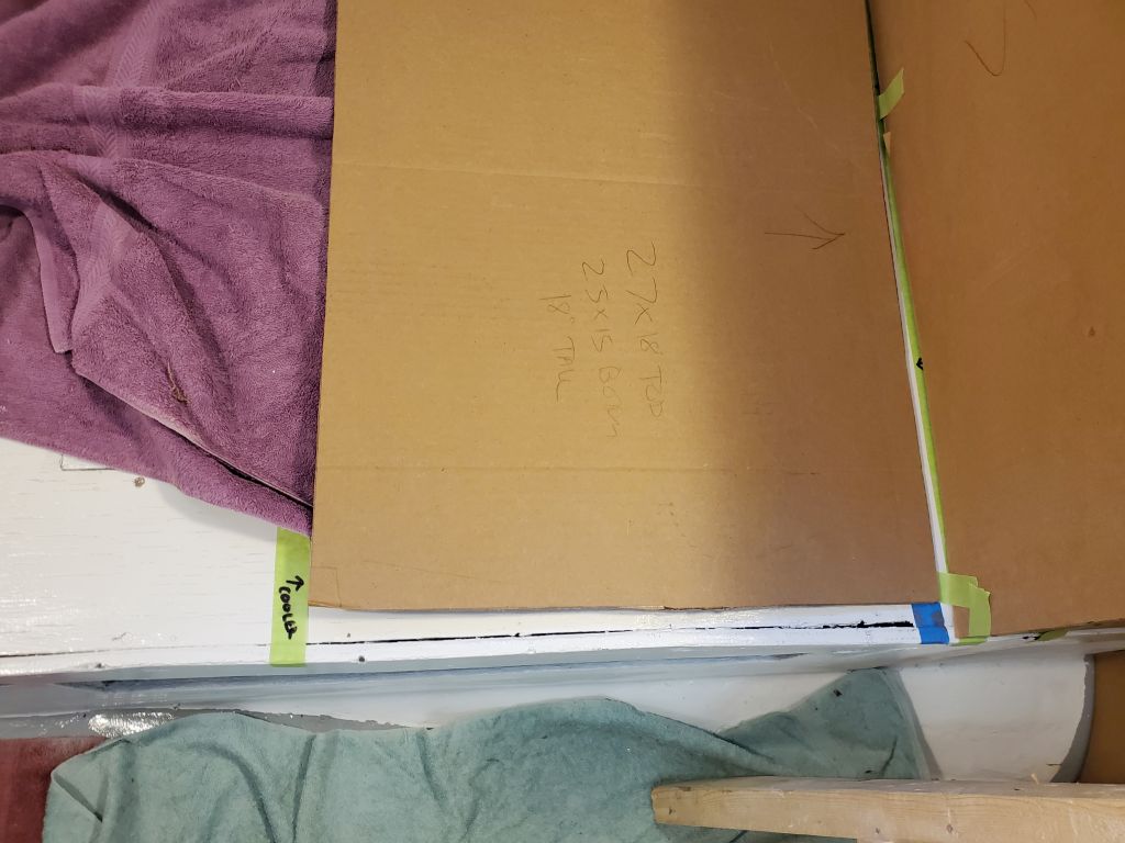
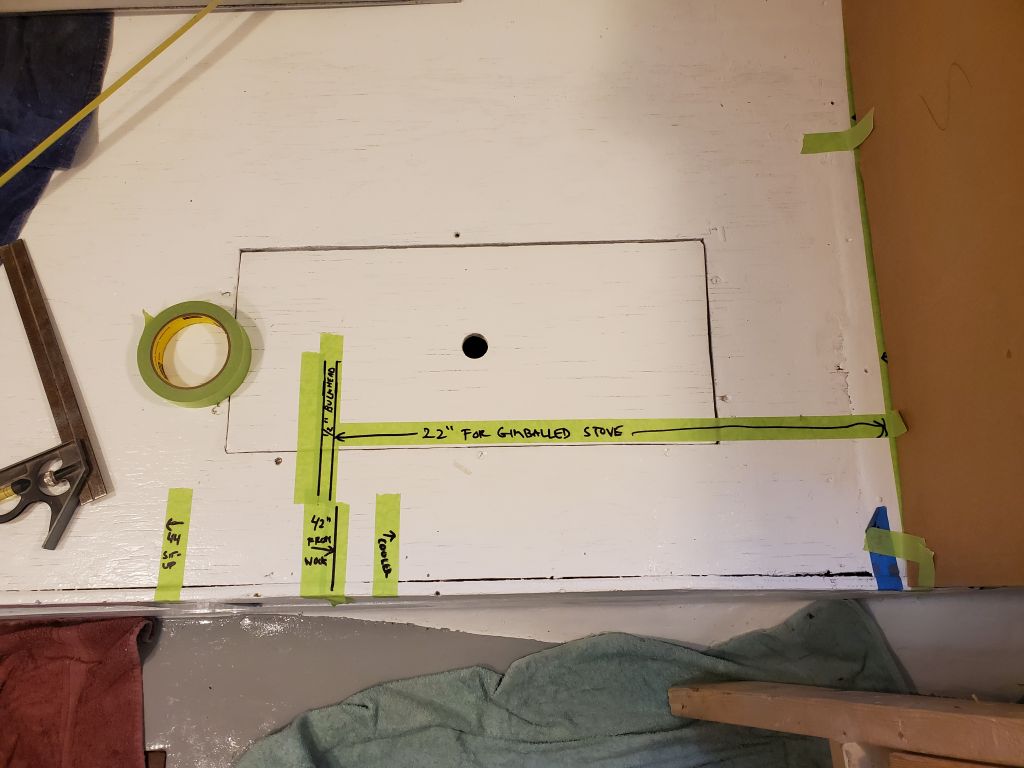
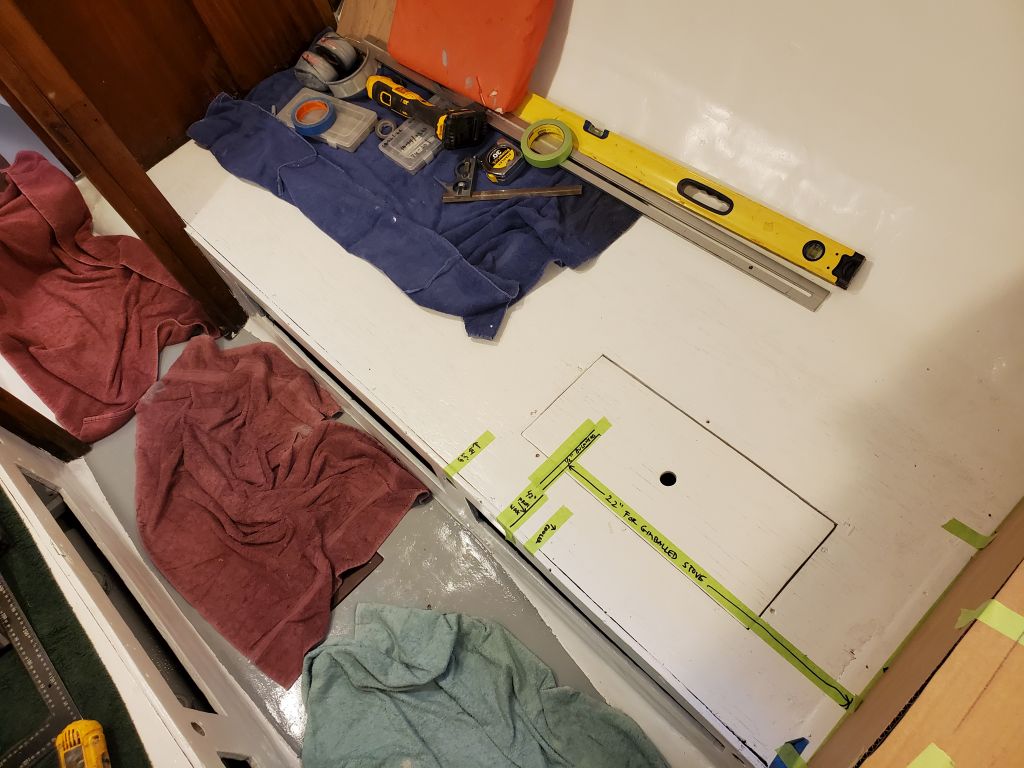
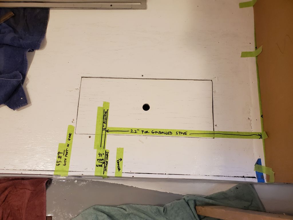
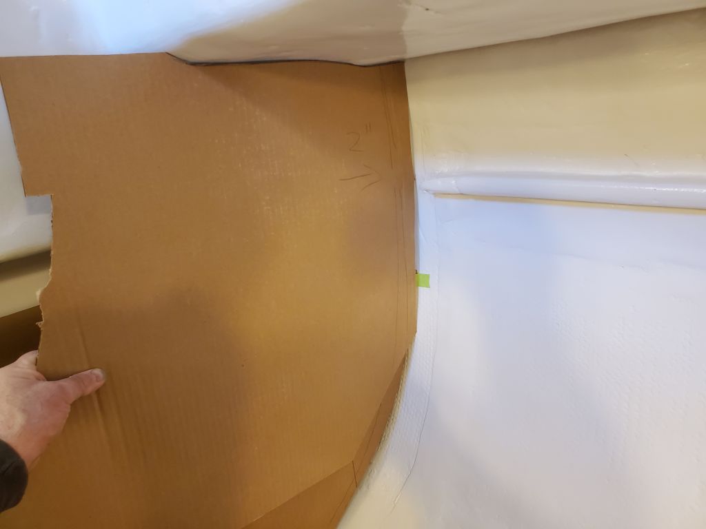
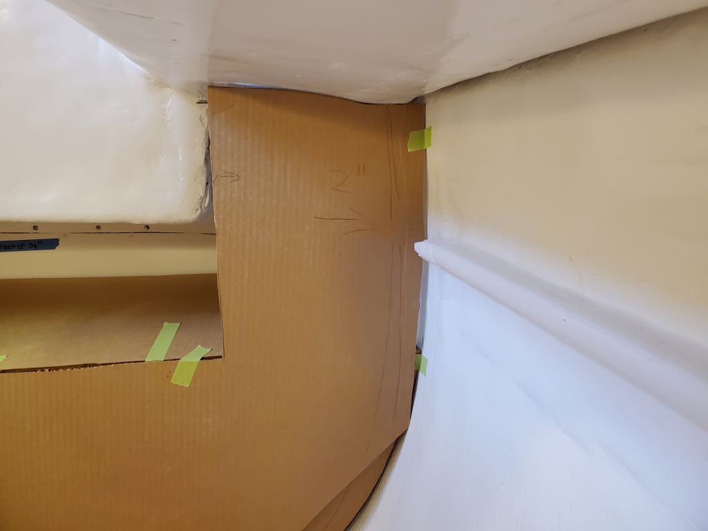
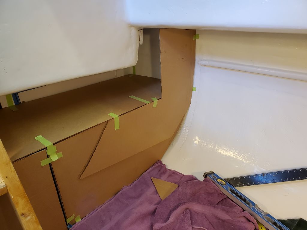
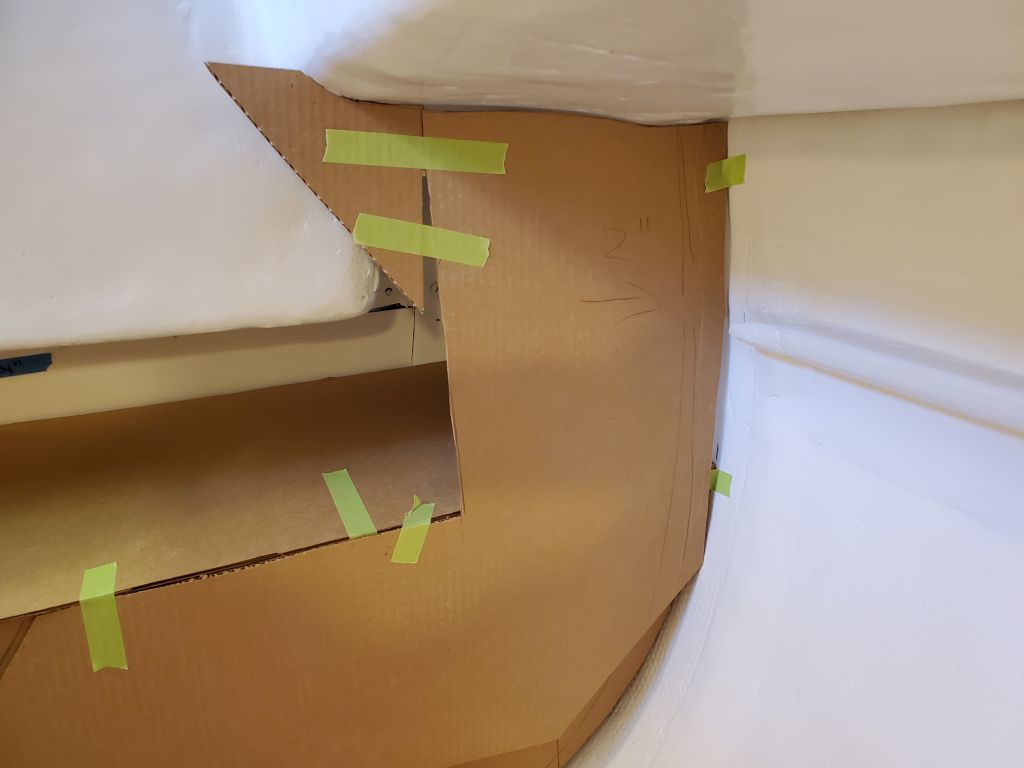
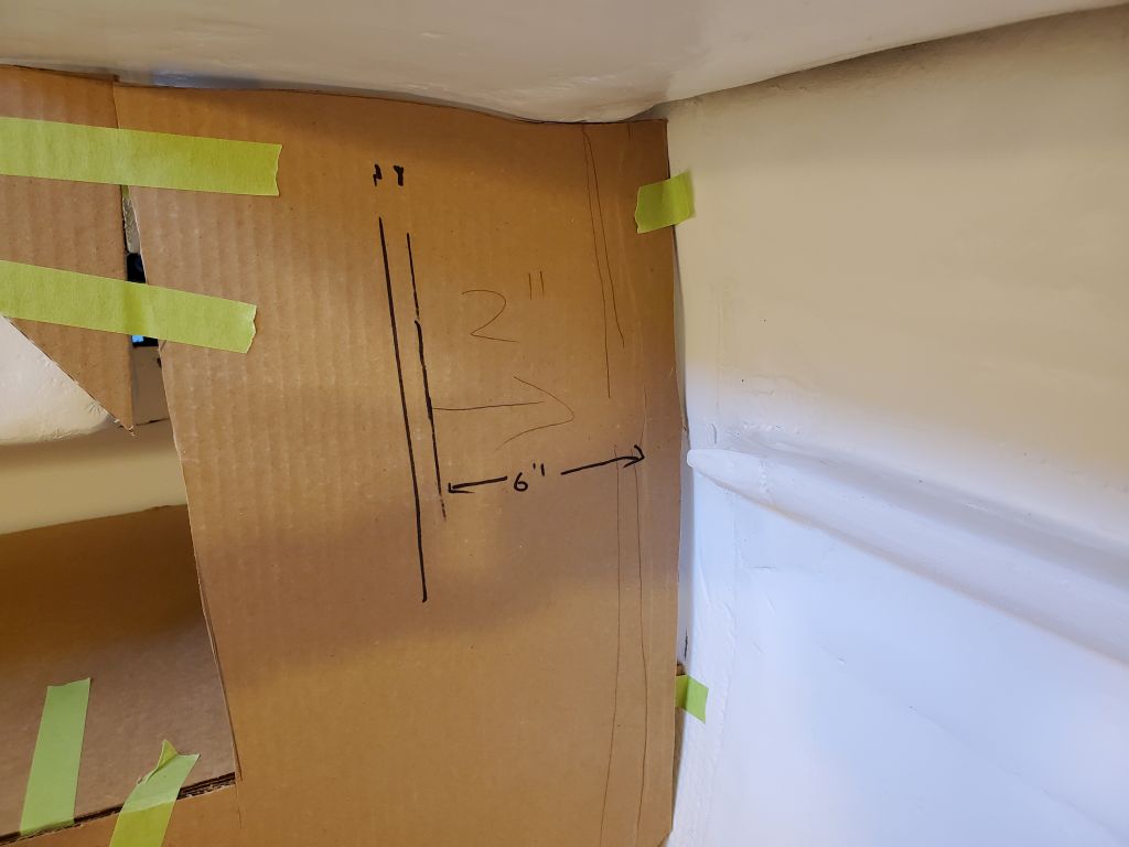
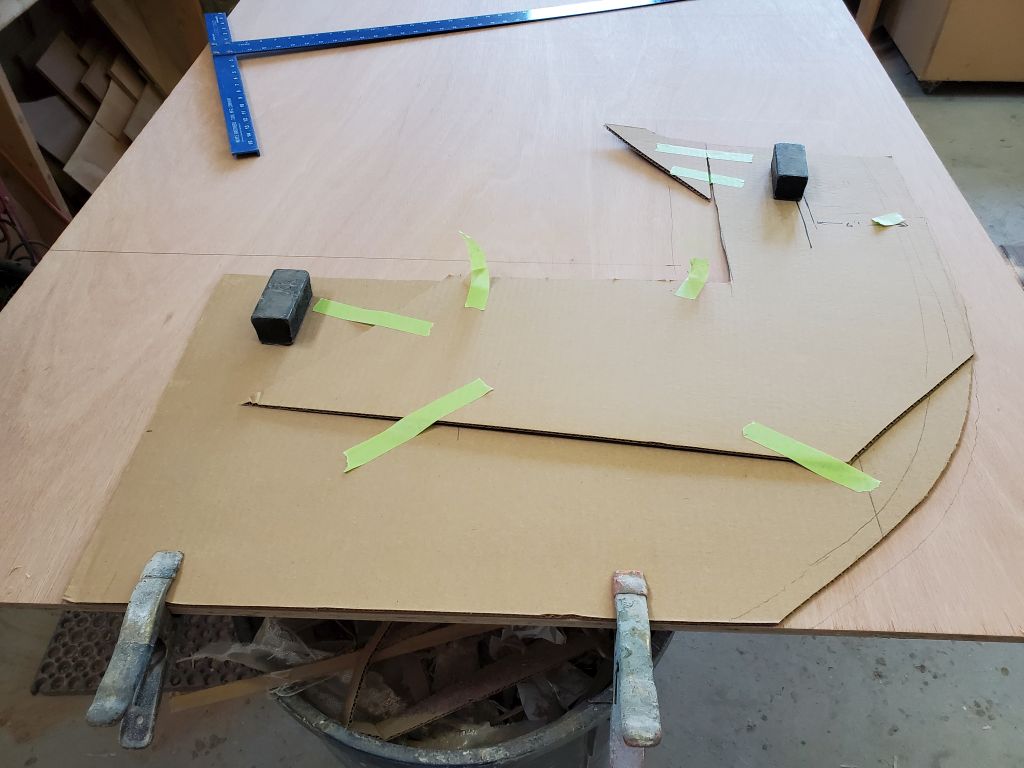
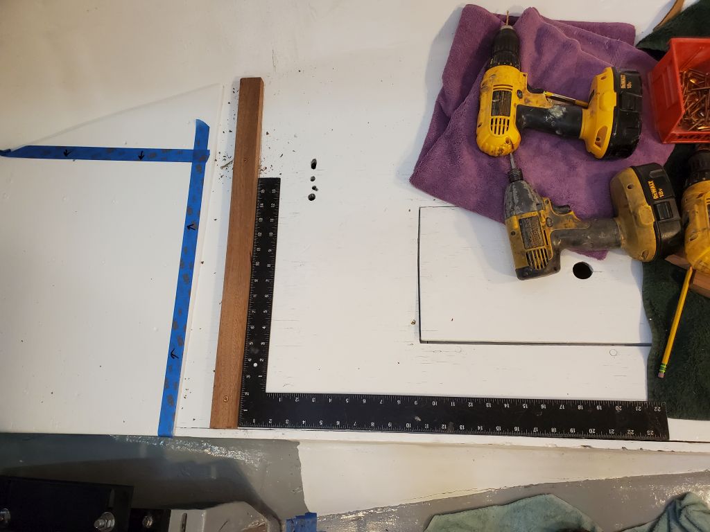
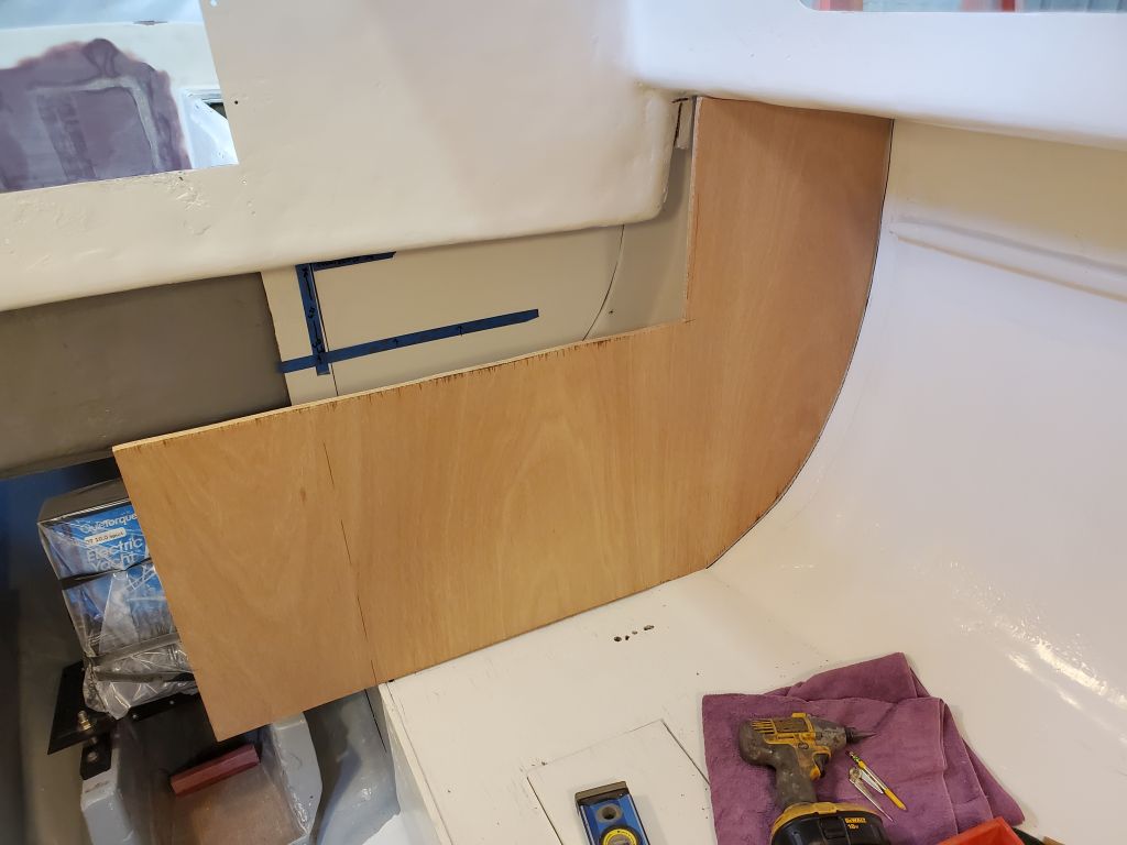
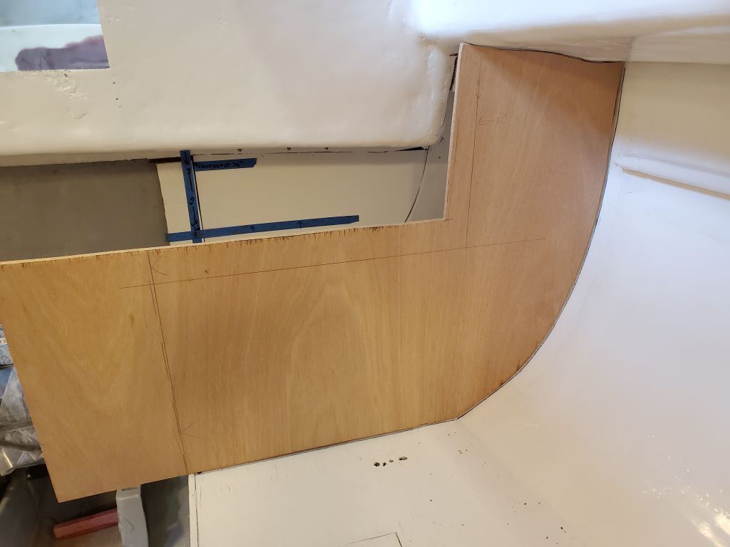
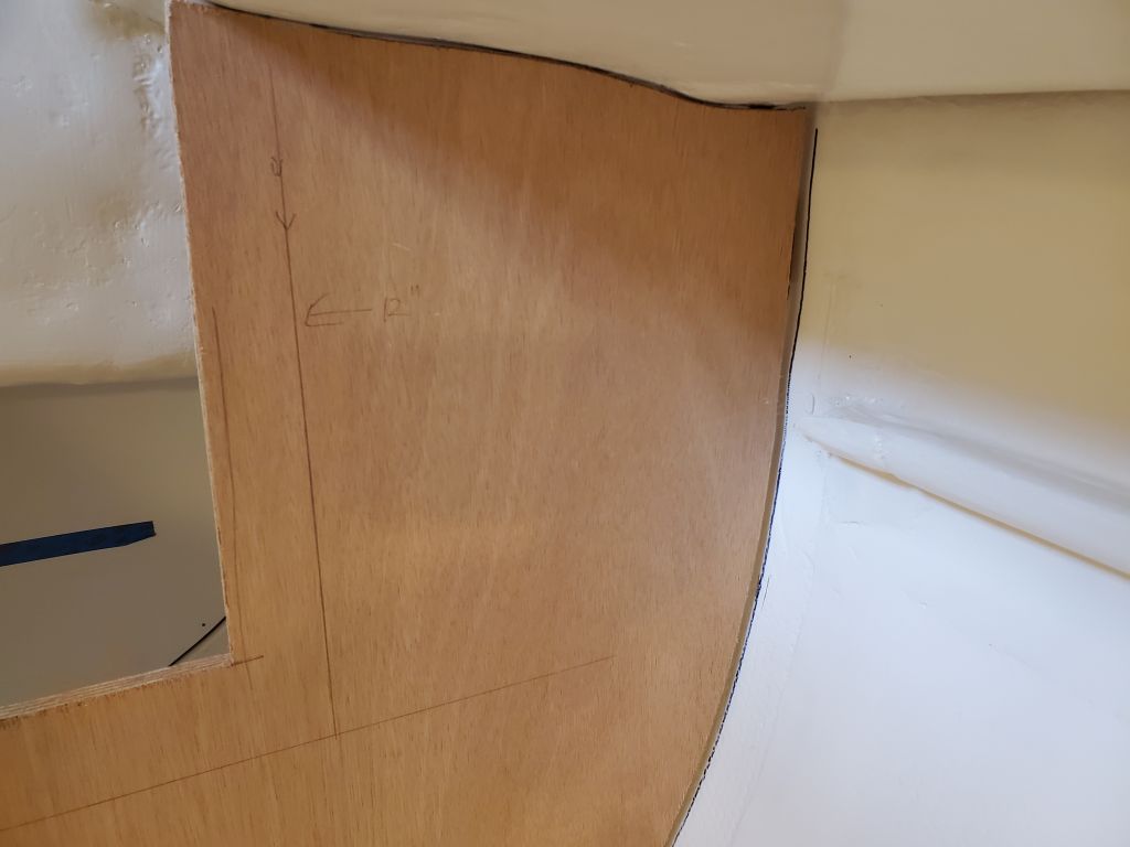
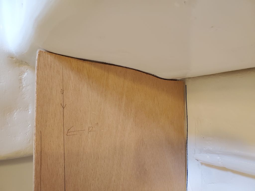
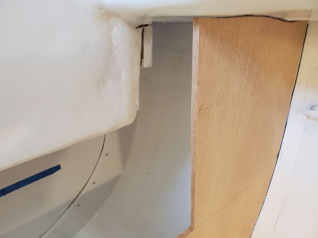
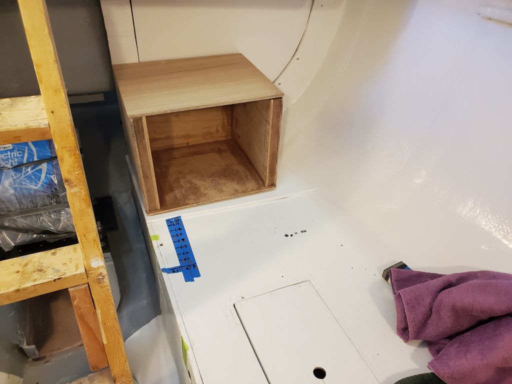
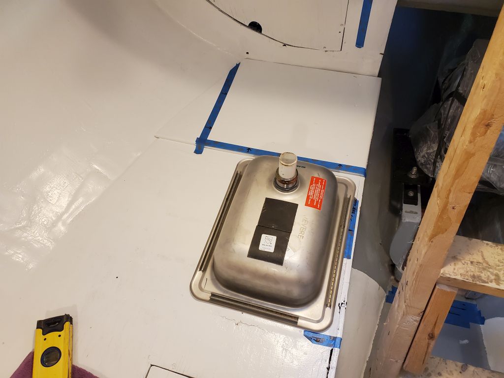
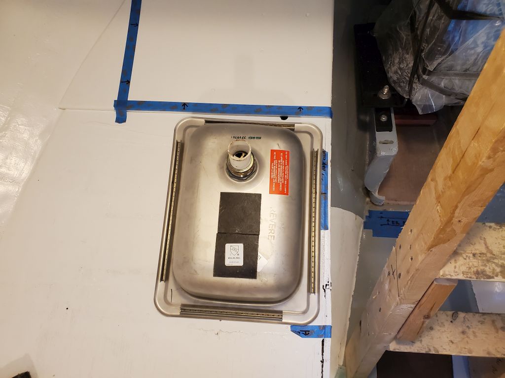
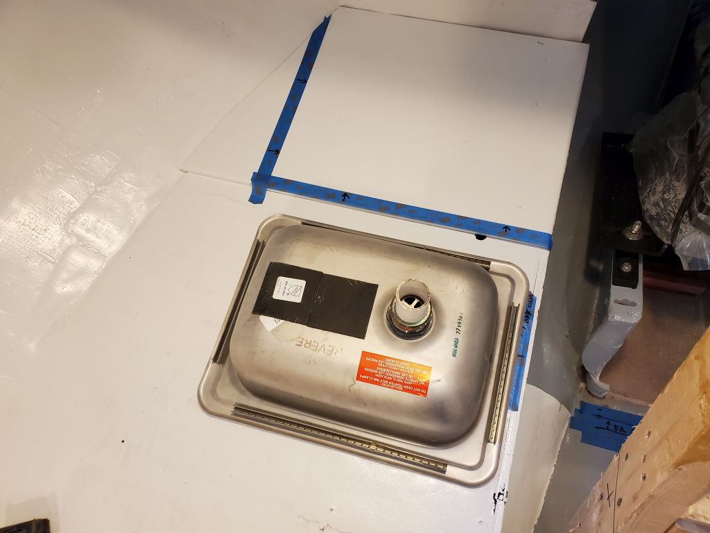
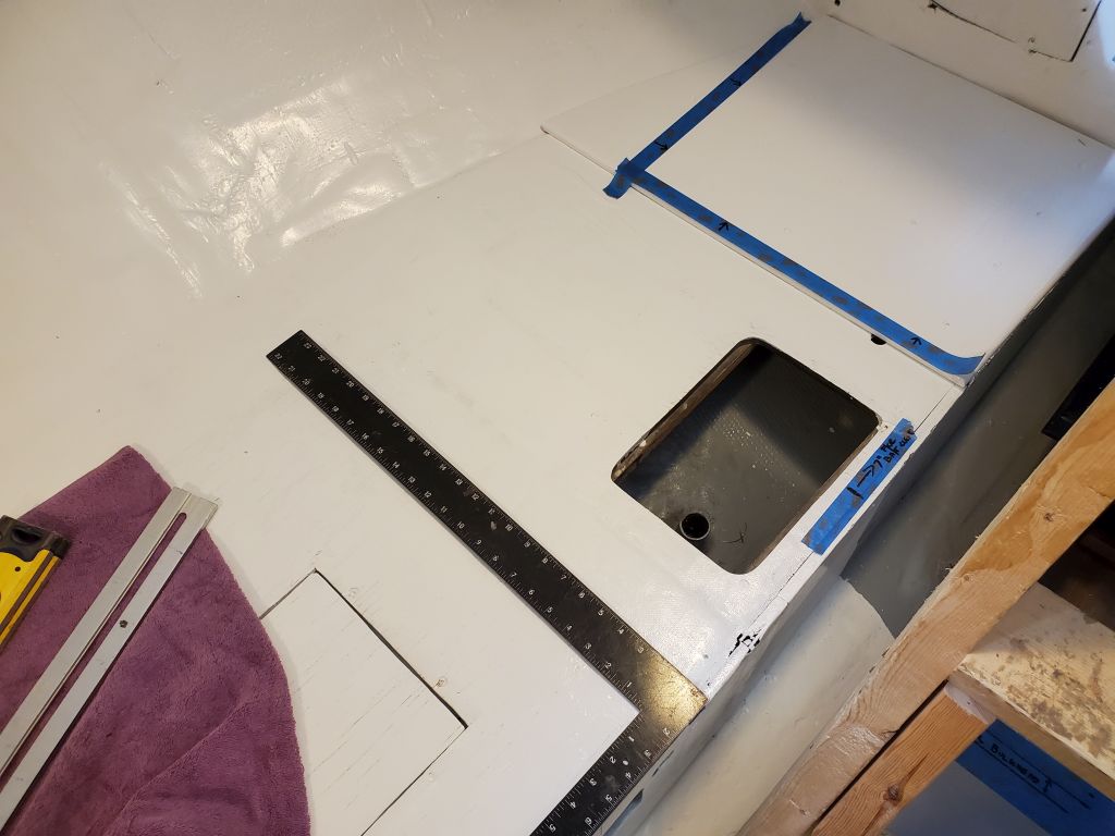
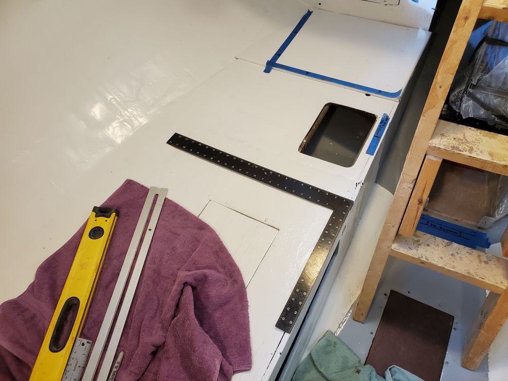
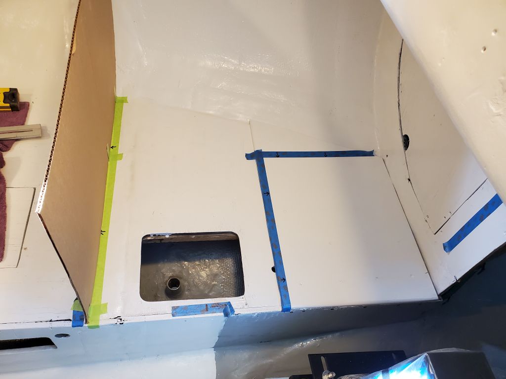
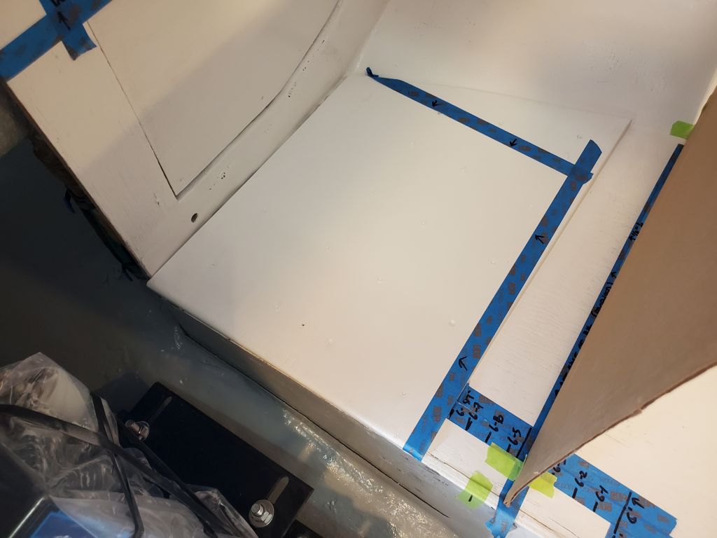
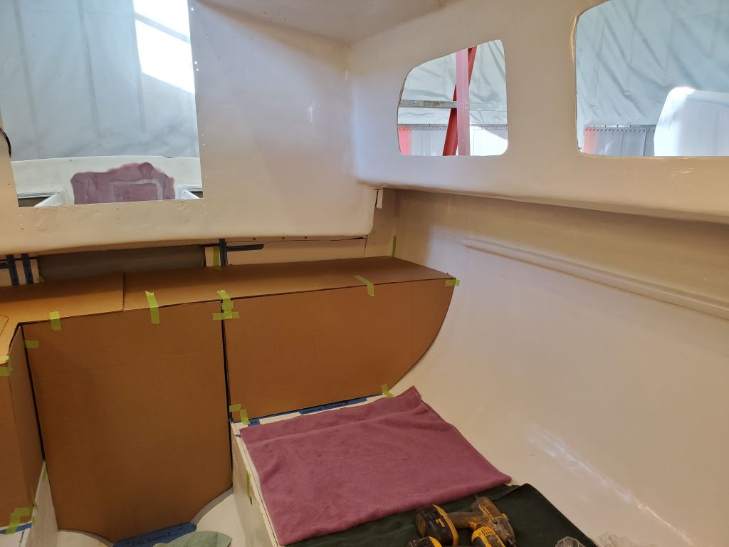
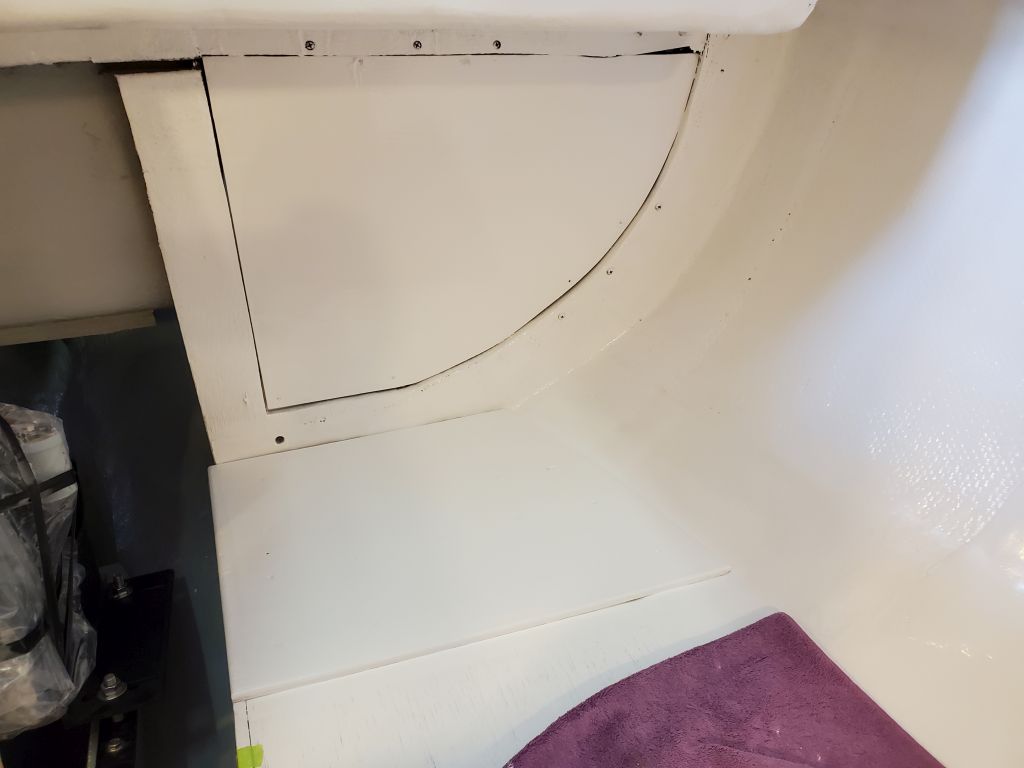
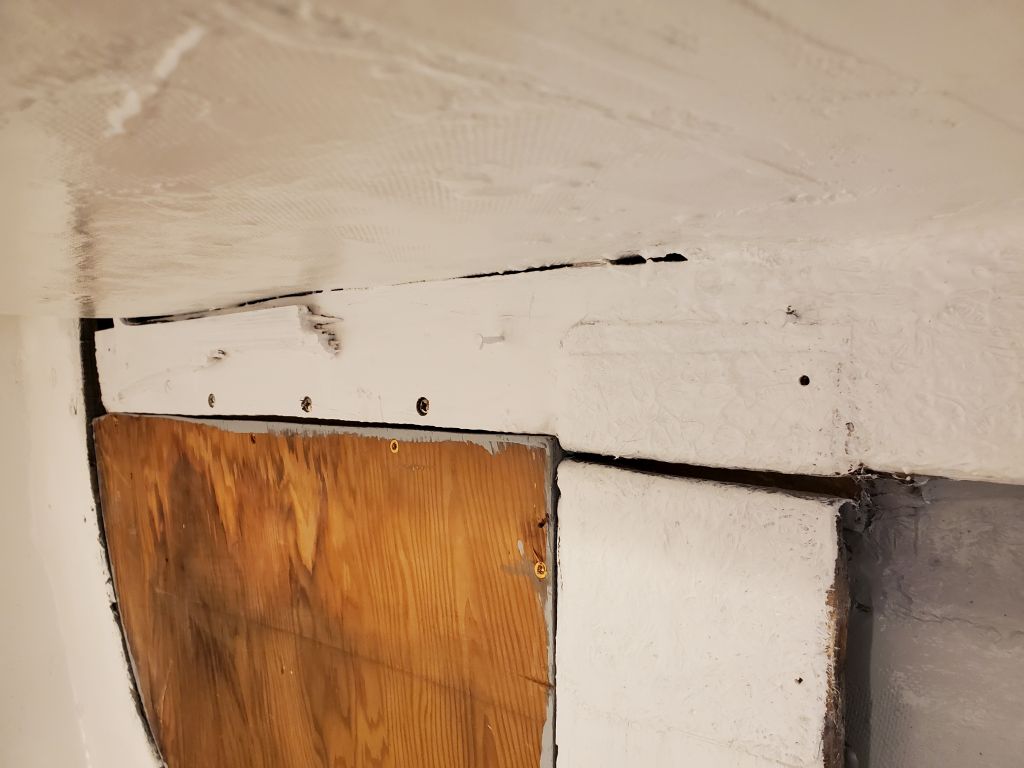
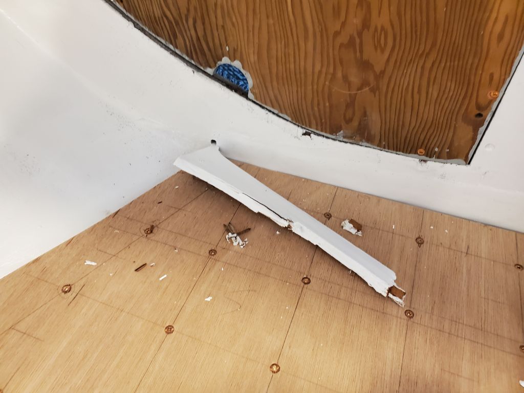
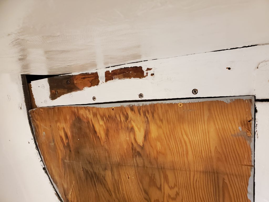
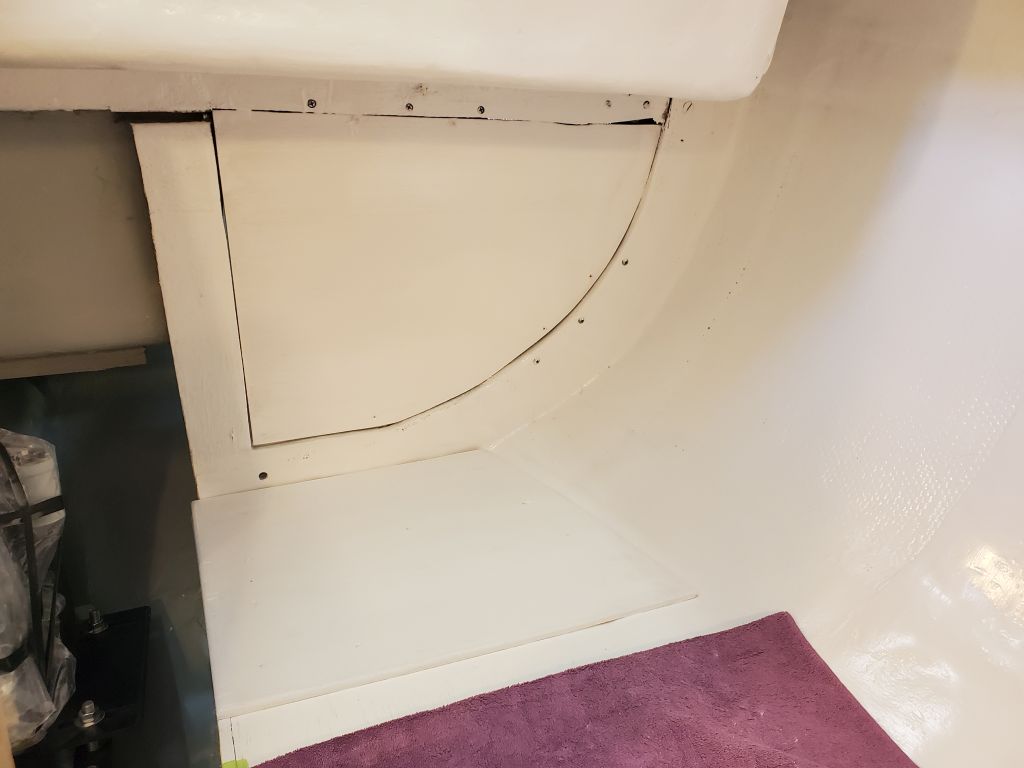
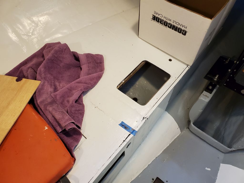
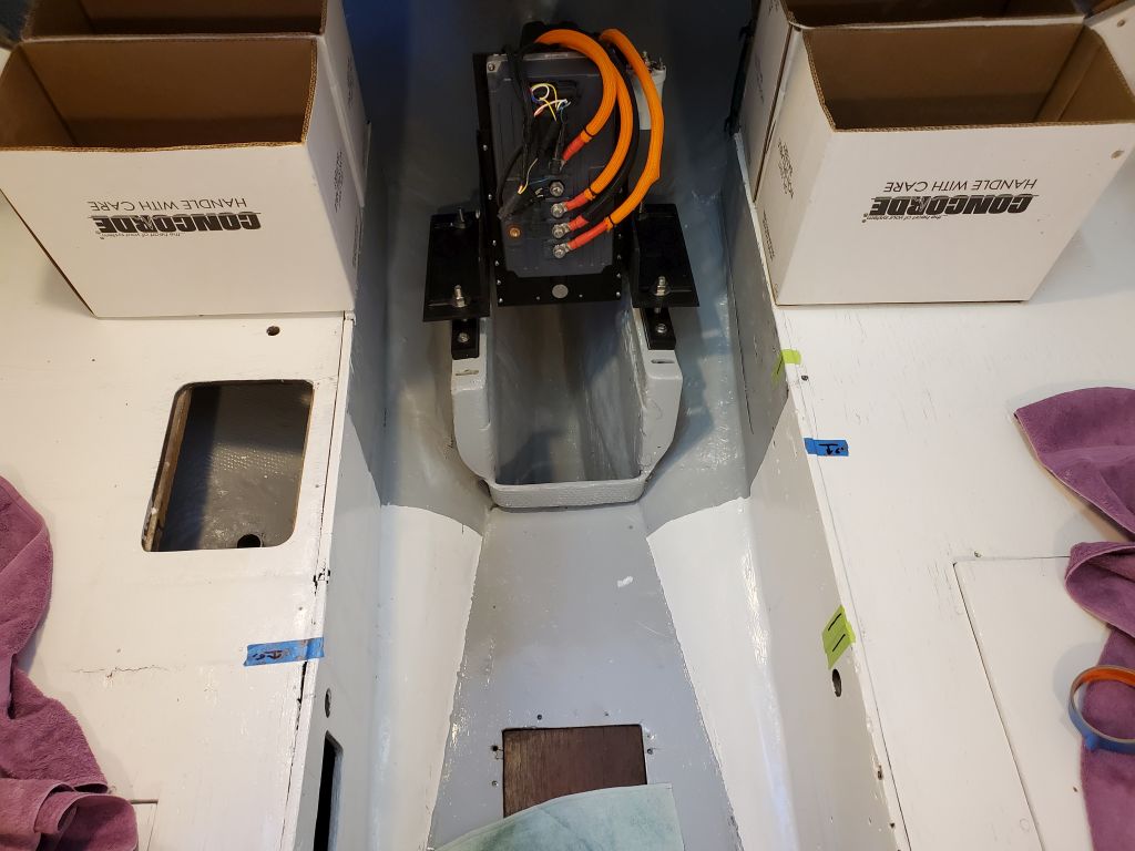
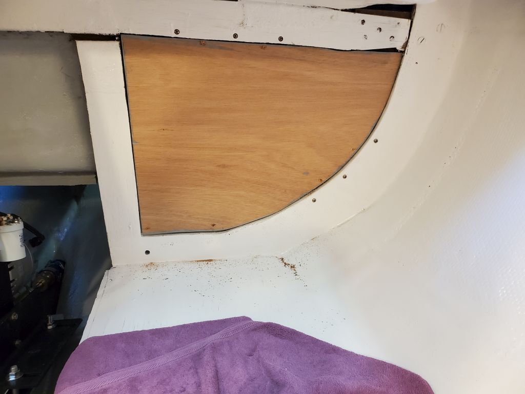
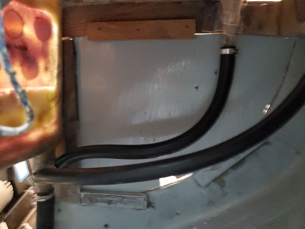
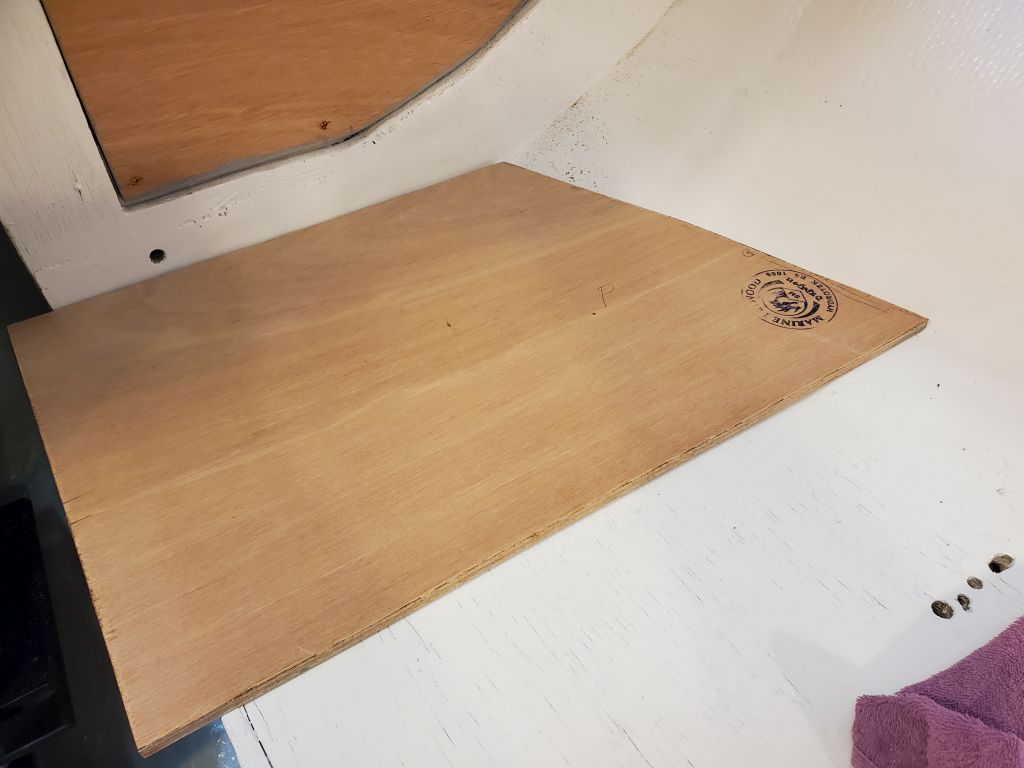
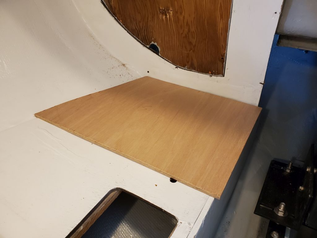
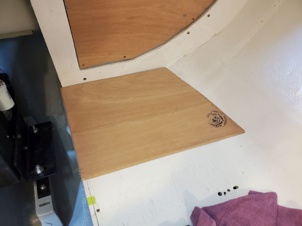
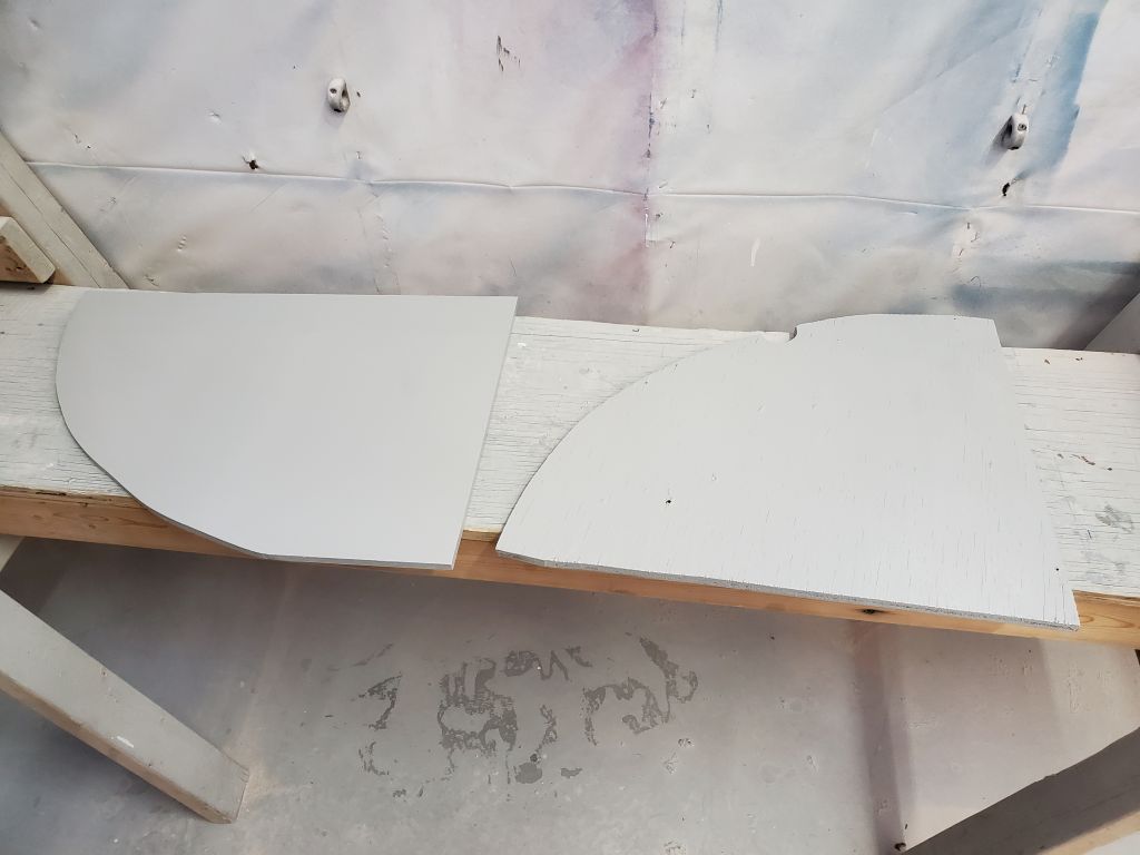
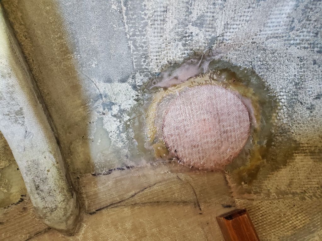
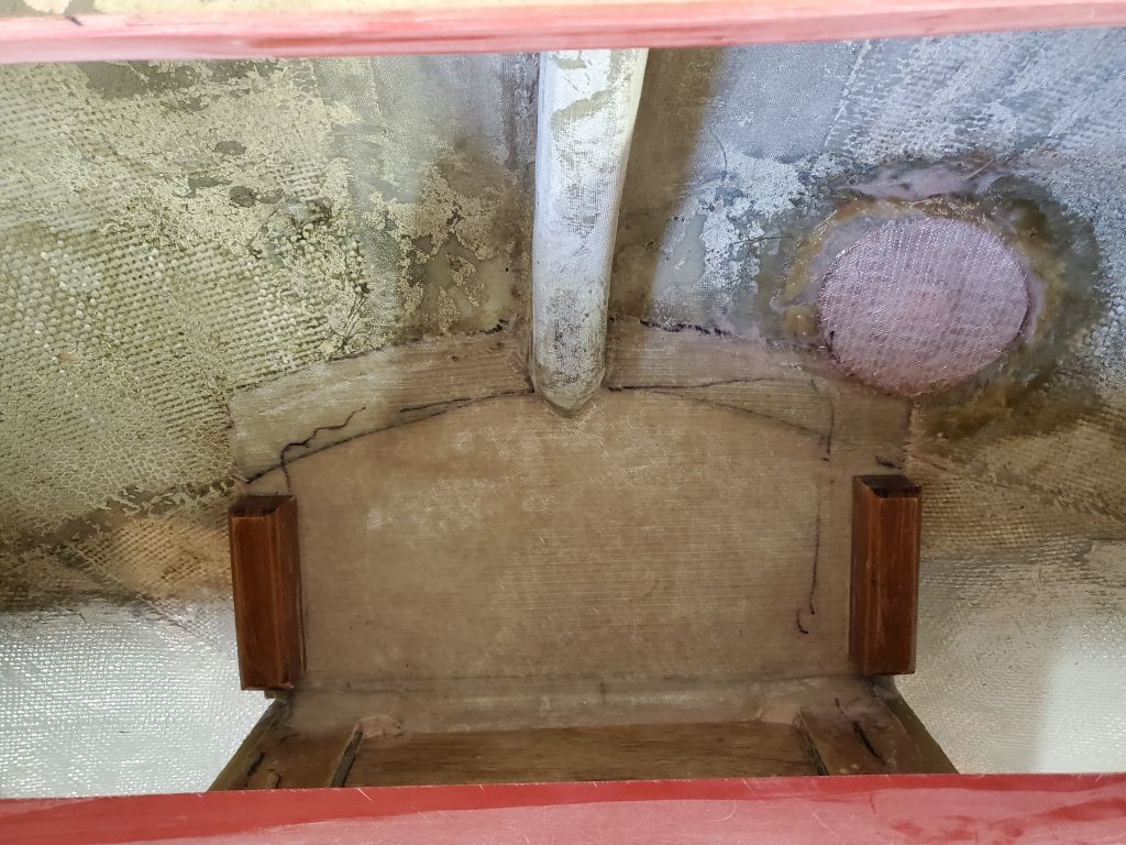
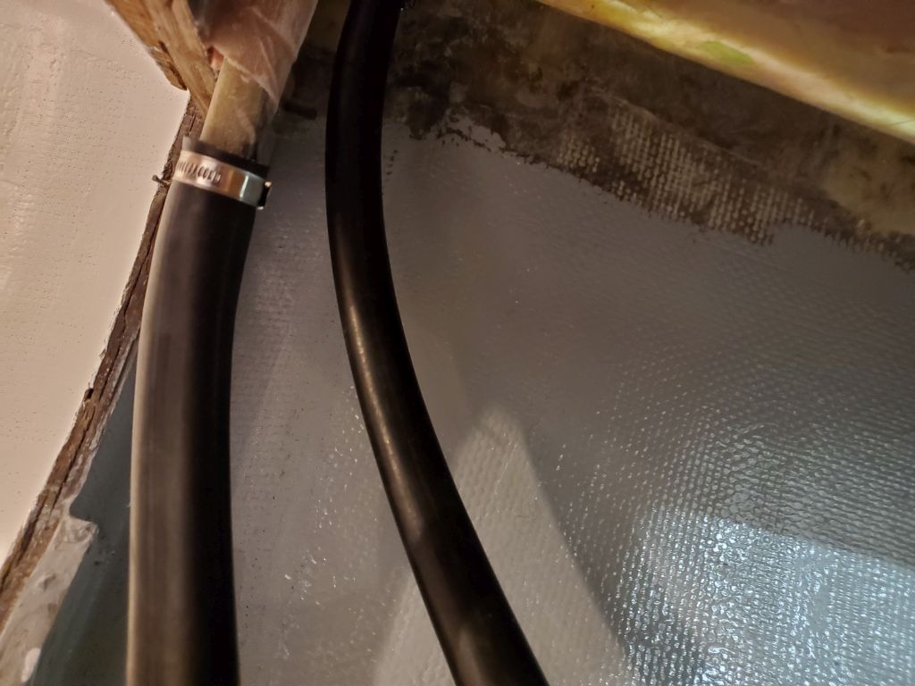
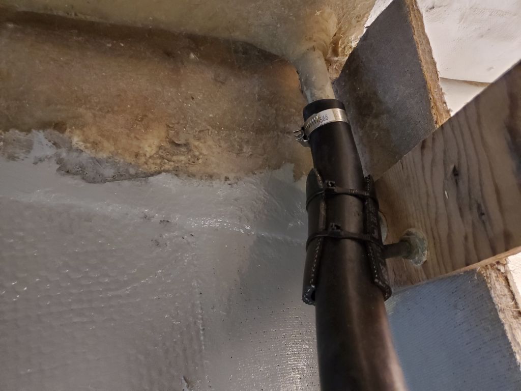
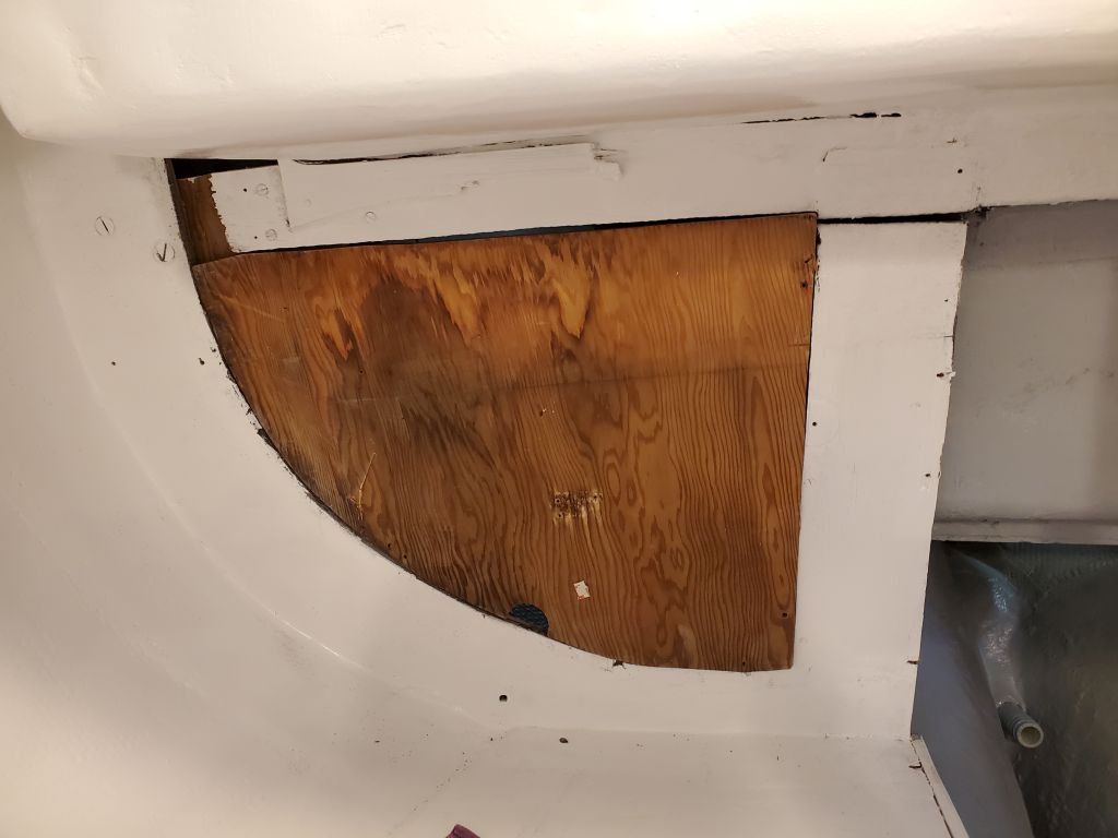
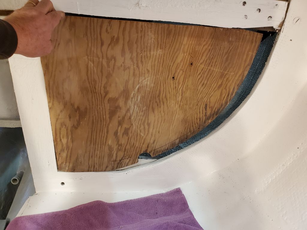
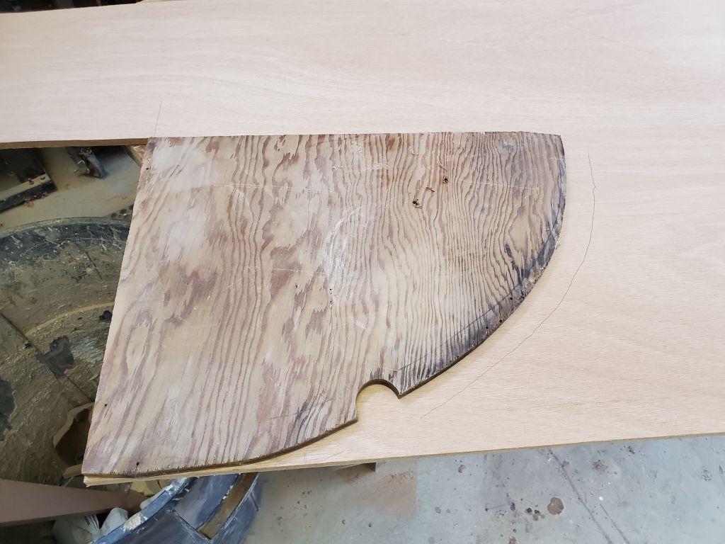
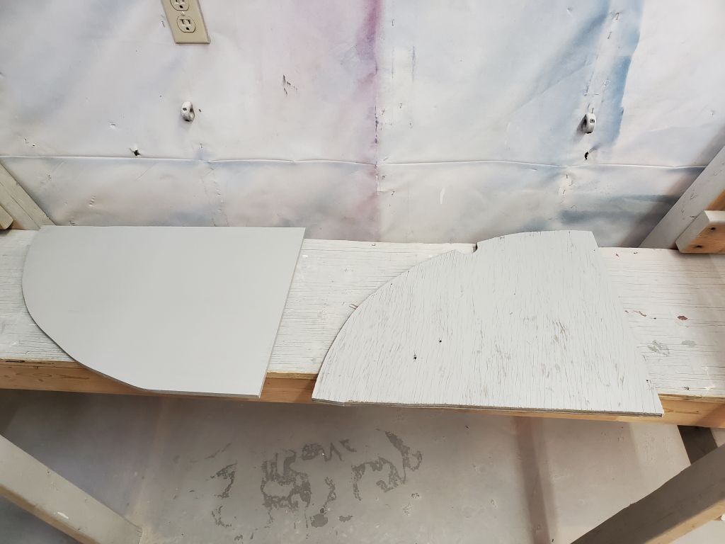
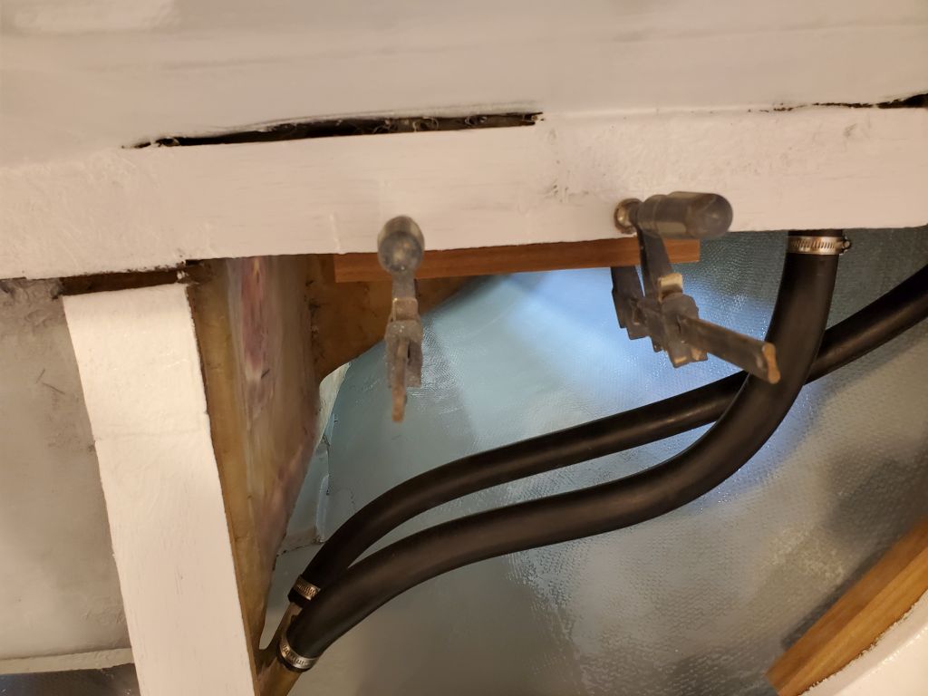
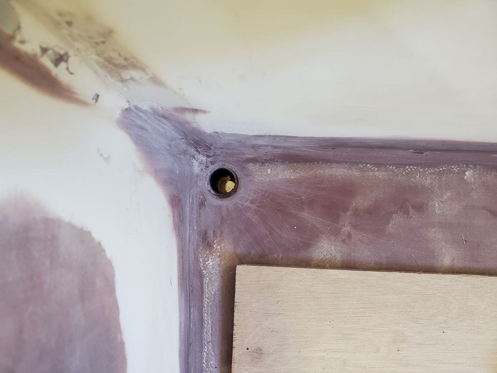
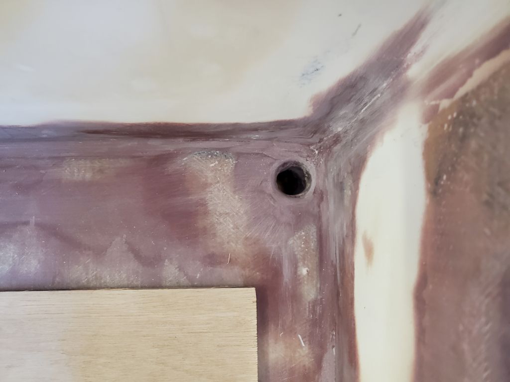
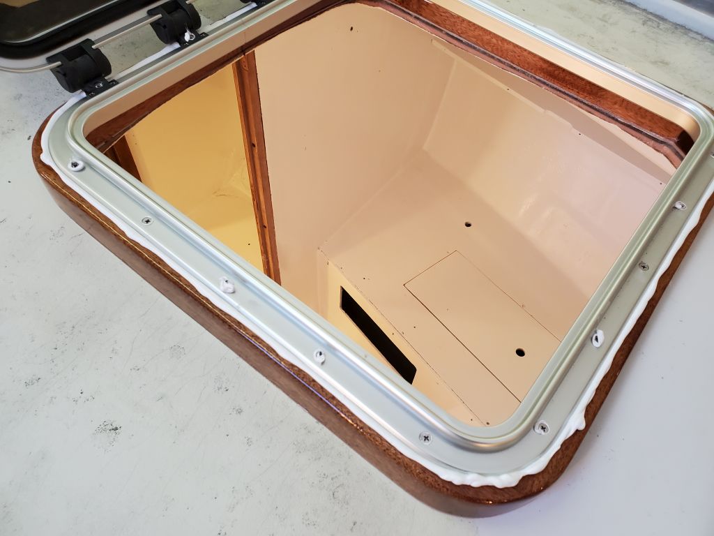
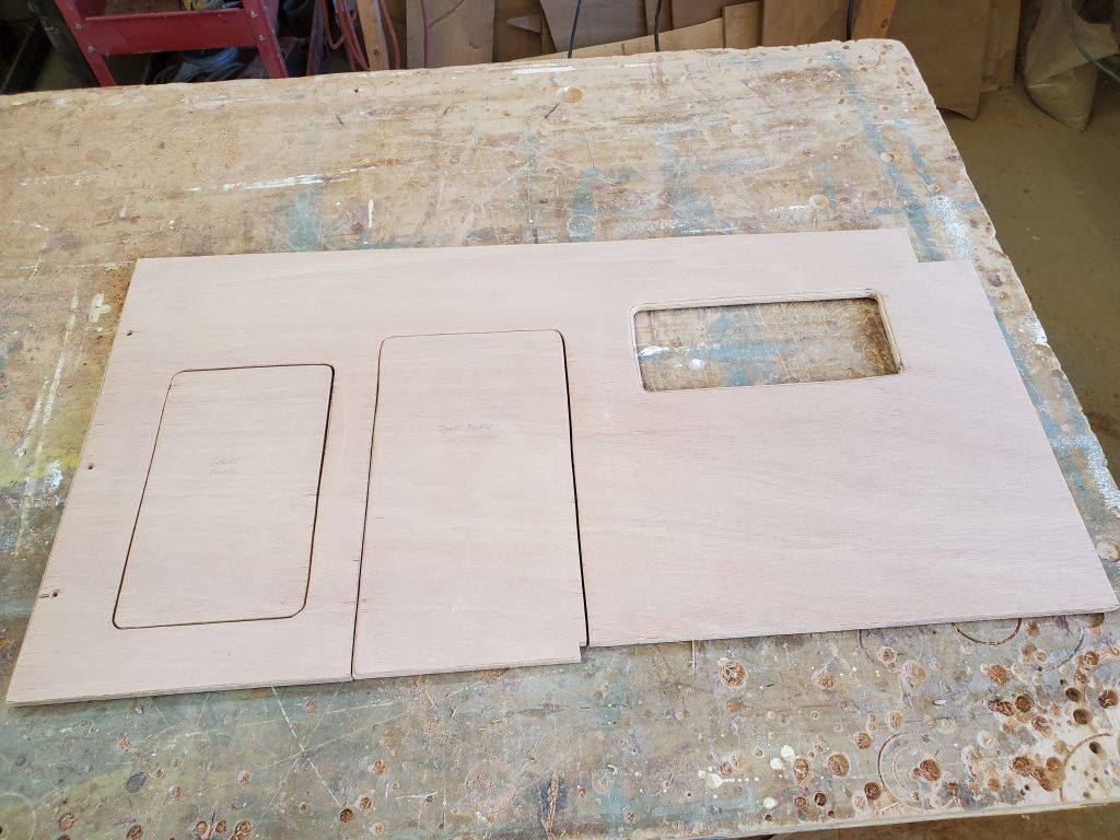
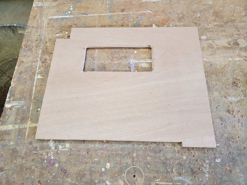
Earlier, while installing the battery boxes, I’d marked the engine room bulkheads in way of the battery box wiring holes, and now down on the bench I cut out oversized sections to provide clear passage for the wiring through the narrow space between the bulkheads and batteries.  Meanwhile, I finalized the cutouts on the starboard side, including the battery access panel and, just forward, an opening for access to a storage locker beneath the sink.  These bulkheads awaited final installation next time.

Total time billed on this job today:  6.25 hours

0600 Weather Observation:  35°, cloudy.  Forecast for the day:   Partly sunny, 53°

Lyra 35

Wednesday

The battery boxes required another coat of paint, as the first coat (as is typical) soaked into the new plywood, so although I’d been hoping to install these today, needs must, so I applied a second coat of paint.  I had enough to do and didn’t absolutely require the boxes right away.

In order to finalize the size of the port bulkhead–specifically the vertical extension to the sidedeck–I had to determine how much depth the electrical locker, which would abut the bulkhead on the forward side, required for what the owner planned to install within.  The deepest installation was likely to be the VHF radio, which I had on hand and measured at about 5″ to the end of the housing plus room for wiring connections, so around 6″ minimum clearance required.  To this, I added 1/2″ for the plywood front (assuming the front of the panel would be flush with the aft bulkhead), and an extra 1/2″ for good measure to arrive at 7″ total.

On the bulkhead, I marked a plumb line at 7″ from the closest part of the hull, then removed the bulkhead to make the cut and also cut out the large battery access panel in the front, saving the cutout piece to use as a hatch at least for the short term.  The new, slimmer bulkhead looked right and afforded much better access to the aft corners of the space, including the nook between the cockpit and side of the hull.

Using the cardboard mockup, I cut out a blank for the starboard galley bulkhead, leaving it overlong and over tall for now to allow final in-place marking and trimming.  I installed a hardwood cleat on the settee at the marks I’d made and 90° to the settee front–the most immediate and logical reference for whatever might be “square” in this boat–and temporarily installed the bulkhead plumb using some hot-glued blocks on the hull for support.

The bulkhead fit well against the hull and required no further trimming there.  At the inboard end, I struck a plumb line from the settee face, and with a level transferred the height of the port bulkhead across the boat.  To help with this I cut a little notch in the waste portion of the starboard bulkhead so I could more easily run the level across.  I had to mark the top edge of the new bulkhead this way because the settees from side to side were not accurate enough to use as a measurement, and to ensure the new countertop was level across the whole boat (since it was to be more or less a single surface all the way). I needed to start with what, by default since it had been cut first, had become the permanent reference–the port bulkhead.  Measuring up 17-1/2″–the height on the port side–from the starboard settee had created an entirely new attempt at reality that had little in common with the established reference to port, highlighting the off-kilter fundamentals of the settees on either side.  So by transferring the port height, and establishing level off of that, I ensured the whole countertop would be in keeping with itself.

Figuring out how to measure, plumb, and level off a 60 year-old construction that was never accurate to begin with is one of the more enjoyable challenges of the job.

Now I could remove the starboard blank and make the final cuts down on the bench.

I used a level off the new bulkheads to establish a line across the aft end of the space, on the original aft bulkhead, which would define the aft edge of the countertop.

With the transverse bulkheads established, it was time to build the two short longitudinals that would define the engine room and enclose the two galley areas.  With basic measurements, I cut two blanks of appropriate size and, with a few fine tunings, fit them to their respective spaces and leveled off the top edges accordingly.  As needed, I installed support cleats on the settee and adjacent bulkhead to support the new panels; the after ends of the panels (at least I thought for now) would be supported by the battery boxes once installed, so I held off installing any cleats in those areas pending final battery box installation.  These panels extended just past the edges of the original aft bulkhead on each side of the engine room.

With the galley basics cut and fit, they could await final installation in the near future.  For now, though, I removed everything to make room for some additional work at the aft bulkhead, starting with a basic cardboard pattern of the space above the new countertop line.  The original “bulkhead” was an el-weirdo mishmash of different pieces, rough carpentry that would make a first-day high school apprentice wince in pain, and gaping openings, and  quite simply needed to be covered.  I made my cardboard patterns by cutting pieces roughly to size, then using a compass set at a fixed measurement to scribe the Roz Chast-inspired contours of the hull, deck, and elsewhere.  This simplistic and quick approach has always worked well and accurately for me.

Setting those aside for now, I milled and installed a hardwood cleat across the bulkhead, with its top edge even with the line I’d struck earlier.  I found a suitable offcut of old Honduras mahogany–which I’d not seen in many years since it is no longer widely available on the market (I miss it)–that had to date to the early 2000s in my shop.  The long narrow strip from which I cut my cleat was not of much use for anything good, but would make an excellent cleat.

I installed the cleat with screws into the bulkhead, with some shims behind where the cleat spanned the new plywood filler piece on the port aft side.

Finally, using some reference marks I’d made while the panel was in the boat, I laid out a few things on the starboard engine room/galley panel, including the minimum required opening to allow battery passage (marked by the outside edge of the green tape), and the sink bowl (outside margins of the blue tape).  I also marked the drain location for the sink for reference.  I thought there was a need and desire for access into this potential storage space, not to mention hose maintenance access, and while probably a second opening (and eventual door) made sense for this, since the battery opening was partly in and partly out of the engine room (and front panel, which was to come), but wanted to highlight the situation to help better showcase it for the owner so he could make the most informed decisions possible.

Total time billed on this job today:  6.5 hours

0600 Weather Observation:  25°, cloudy.  Forecast for the day:   Mostly sunny, 48°

Lyra 34

Tuesday

After some discussions and back-and-forths with the owner about the initial cardboard layout of the new galley, I started the morning with a few additional measurements and confirmations, including a reality check on the static waterline position to ensure that the countertop and sink were to be as expected.  I took a rough measurement from the rubrail outside the boat, then transferred this measurement to the galley, where I made some reference marks, along with a mark for the 5″ depth of the supplied sink.  No surprises here.

I also confirmed some measurements from the starboard bulkhead (inside and outside the nook) to the forward edge of the cooler, as well as some early layout to determine measurements and positioning possibilities for a future stove forward of the main galley countertop.  This wouldn’t happen now, but the exercise confirmed the possibilities and, eventually, confirmed that the current position of the forward galley bulkhead, as represented by the cardboard, was where it should be.

It came as no real surprise when one of the cleats holding up the bilge hatches broke free.  I’d been hearing ominous cracks underfoot for a while, and from the getgo had worried whether the new cleats would be able to work with just epoxy, since the old plywood cabin sole was in marginal condition.  Indeed, the wood failed, not the adhesive, when the forward cleat on the aftermost hatch gave way.

This was disappointing, but I took a few minutes to reinforce the cleats in this opening with some through bolts, supported by large washers and nuts beneath.  This felt a little like shuffling deck chairs on the Titanic, as the sole was just soft would need further real attention in the future, but hopefully it would serve the purpose for the immediate future, as we just couldn’t do it all now.  I’d probably go back later and add preventive bolts to some of the other cleats at the other locations, just to be sure, but that could wait for now.

On the port galley bulkhead, I added an extension to bring the outboard edge of the bulkhead up to sidedeck level, creating an oversized panel for now so we could determine its final width later.  This extension would serve as the starting point for the cabinetry forward of the galley on this side, which would include (most significantly for now) an electrical locker to house panels and wiring.  Something might happen aft of the extension as well, in that tough-to-reach corner of the galley and the little nook above, between the cockpit and the side of the boat.

With the port template complete, I disassembled the entire “Whitefield mahogany” galley so I could start building the real thing.  I chose to begin with the port bulkhead, and used the cardboard template to transfer the shape to a new sheet of 12mm meranti plywood.  I left the upper extension much wider than its final size to allow for options and trimming, and left the bulkhead a couple inches too tall, and let the inboard end hang out over the engine room, all to allow accurate final marking and later trimming.  The first fitting was close, but I rescribed the hull edge and made an additional cut to bring the whole thing to where it needed to be.  To support the lower edge, I aligned and installed a hardwood cleat on the settee, choosing as my reference the inboard edge of the settee.  This location, as earlier determined, was 6′-4″ aft of the forward bulkhead.

Satisfied with the basic fit, I plumbed the bulkhead and made various reference marks with a level, including a vertical line to trim the bulkhead at the engine room side; a horizontal (level) line to cut the bulkhead at its final height (17.5″ above the settee, allowing for the 1/2″ countertop to bring it to the final 18″ height), and another vertical line 12″ from the hull on the outboard side, where I could cut the upper extension plumb.

After making these cuts, I laid out a proposed hatch or door opening into the bulkhead.  This large opening, defined by the outside edge of the green tape, was designed to allow battery installation or removal to the battery box behind, as well as ancillary access to the storage areas remaining in the space.  I might have extended it further outboard, but to do so would probably impact the port settee back cabinetry, specifics of which were still unknown at this point.

I planned to cut back the vertical extension fairly substantially later, once we had determined how deep the electrical locker–to be located just forward of this–needed to be, as well as after resolving various related questions about what might be behind the bulkhead too.  These questions would soon be resolved once the owner and I chatted about them.

Speaking of the battery boxes, I was required to take care of one final task before I could call them complete and send them to the paint room (as it were):  The boxes needed openings in the sides to allow passage of wiring, and which would also serve as vent holes.  With large cables to be run in and out, I made the openings large (2″ holes), but narrowed the openings at the top to retain plenty of the solid wood banding there for the screws securing the top.  I rounded over the openings on both sides and sanded things smooth before cleaning up the boxes and applying gray paint to all surfaces, including the front and top panels.  (I’d already done a successful paint-curing test on some of the fresh epoxy.)

Total time billed on this job today:  6.25 hours

0600 Weather Observation:  30°, cloudy.  Forecast for the day:   Becoming mostly sunny, 46°

Lyra 33

Monday

I lightly sanded the battery box tabbing as needed to prepare the boxes for their final construction steps and finishing.  Afterwards, I dry-assembled the removable front and top panels to show the completed box; I’d finish the details on these panels soon, but was awaiting some materials.

Bringing the boxes and a lid into the boat, I could begin some of the critical galley layout.  The large battery boxes, and maintaining access thereunto, was to be a substantial factor in determining various details of the galley cabinetry, along with myriad other considerations, limitations, and desires.

On the port side, the owner wanted to maintain a full-length berth of at least 6′-2″, so to begin I made myself a little reference guideline showing various lengths on the port settee.  The secondary plywood underlayment beneath the battery box would limit the aftmost placement of the bulkhead, and the minimum berth length the forwardmost location, so that gave me about six inches of space within which to work, depending on other factors that would make themselves known as the layout continued.  With clear access ahead of the battery box, it would be straightforward enough to incorporate usable access to the battery box for installation or removal of batteries; those details would come later.

On the starboard side, which would incorporate a more typical galley cabinet and on which side the owner planned to sacrifice overall berth length in favor of galley needs, one thing I needed to think about from the getgo was a way to manipulate batteries in or out of the battery box once all the cabinets were installed.  While I planned top access on both sides to allow inspection, wiring connections, and so forth, space limitations and physical impediments meant that it wasn’t possible on either side to actually lift in or out the batteries from the tops of the boxes:  The bridgedeck was too low, and the batteries too large and heavy to manipulate that way in any event.

So my plan to starboard was to build an access panel or door in the side of the galley cabinet, aft of the sink plumbing, that would fit the batteries’ width dimension of just under 7″, allowing the batteries to be slid in or out of the box and through this opening.   I measured forward the 7″ distance and made a reference mark on the settee for confirmation of the idea and for future reference.

With the lid atop the boxes, I made further reference marks on the aft bulkhead on each side, aimed at determining the final height of the countertop.  The boxes were about 13-1/4″ tall, plus the 1/2″ underlayment, so with a 15″ settee height above the cabin sole, and a theoretical countertop of 36″–a standard for kitchen counters–this allowed nearly 7″ clearance between the underside of the countertop (at this proposed height) and the top of the battery box.  However, this left the clearance between the countertop and the bridgedeck at only 3-1/2″–far too narrow to allow access beneath or working utility.  Looking for a minimum of 6″ clearance, I made some additional measurements from the bridgedeck down, marking these on the bulkhead as well.  At this point, in my mind I settled on a 33″ final countertop height, which was still high enough for comfort and to clear all the requirements beneath, but allowed over 6″ of overhead clearance to the bridgedeck–a key consideration for the owner, and for the general utility of the galley.

With tape, I marked the outlines of the battery boxes (footprint and height) for continuing reference, but moved the boxes out of the way for the duration, and to complete a bit of additional structural work.  I’d changed my original thinking on how to secure the tops of these boxes–I’d been thinking of some hold-down clamps, but ultimately decided simply to use screws, same as my plan for the removable fronts.  So to provide a landing surface for the screws (and threaded inserts I planned), now I had to add some solid wood in the voids at the tops of the box sides, a simple task with more scrap hardwood and epoxy.  To prevent the new inserts from sliding down at all, I hot-glued little strips to the top to hold them flush.

Now I could turn to the fore and aft arrangement of the two sides of the galley.  At a minimum, the starboard side needed to allow room for a sink (on hand) forward of the batteries, and its overall location was more or less dictated by the drain through hull as well.  I laid out the sink with its long dimension fore and aft, as well as sideways, and thought that the transverse arrangement worked better in all ways, so I planned accordingly.

While it wasn’t on the docket right now, the owner thought he’d eventually like a stove forward of the galley, as many Triton owners have done, so for the moment, and to maximize space on the berth ahead at least at these early stages, I located the proposed galley bulkhead quite close to the sink position; this could be easily moved forward in the final construction, but one has to start somewhere.  With this reference point, I used a square to mark the bulkhead position, and cut cardboard (sometimes known as “Whitefield mahogany”, a term coined by a client in years past) to fit–both as a mockup, and perhaps as a pattern going forward.  I taped the bulkhead in place more or less level and plumb all around, and, to match the proposed countertop height, cut the top edge at 18″ above settee level, which was just about 33″ off the cabin sole.

On the port side, my goal for the initial layout was to have flush cabinetry running from the engine room and across the port berth, which meant the engine room dictated the final placement for now.  In positioning this, I allowed clearance for the cleat to secure the house battery in the engine room, and a bit of leeway, then transferred this measurement to the port berth so I could cut and install a mockup bulkhead on that side as well.

With the bulkheads in place, it gave a good sense of the space behind on each side.  The blue tape and arrows represent the battery boxes.  Reviewing the layout later, I noted that on the port side, I needed to factor in enough space to line up the batteries in front of the box so they could be slid in or out; the shape of the boxes probably wouldn’t allow much of an angled approach.  How I laid out the access opening in the bulkhead would ultimately play a role in this, but it was something I had to keep in mind through the rest of the layout and especially in the final construction.

Now I cut more Whitefield mahogany to form the longitudinal panels of the galley on each side, and a vertical panel for the engine room.  The working companionway ladder, which was fairly representative of what would ultimately end up here in the boat (in terms of its angle) cleared the engine room panel by a close, but adequate, margin, but the engine room couldn’t extend further forward without creating a conflict.  With a desire for a flush face across the engine room and port side bulkhead, this pretty much dictated the bulk of the layout, at least for now.  But even allowing for minor tweaks, so far I felt the whole thing was coming together well–more or less as envisioned, meeting most of the multiple design requirements, and looking good, and functional.

With the base cabinets in place, I mocked up a countertop from more cardboard, finishing off the mockup and giving a good sense of things to come.  I made additional reference measurements and marked the sink outline on the starboard countertop.

For refrigeration, the owner chose one of the modern super-insulated portable coolers, and from cardboard I made a rough template to the maximum size of the cooler, representing the top; with tapered sides all around, the base was slightly smaller.  As it happened, the cooler was 18″ high, so its top would be level with the countertops.  With 3″ insulation all around, the inside dimensions of the cooler were in keeping with what seemed appropriate for the boat’s intended use.  The owner planned for now to use it on the starboard side, forward of the galley, where there was adequate room.

With the basics in place, it was time to let the concepts settle out and have some discussions to determine what changes, if any, should be made before building the final galley.  As with all design, various questions, considerations, and potential issues had already made themselves clear, but the fundamental layout seemed to be well workable.

Total time billed on this job today:  6 hours

0600 Weather Observation:  13°, clear.  Forecast for the day:   Sunny, 38°

Lyra 32

Friday

With no plans to do any work in the cabin itself during the day, I could go ahead and apply a coat of the semi-gloss white enamel to the aft bulkheads and battery areas.

I spent much of the day on the battery boxes, starting by removing all the wire ties that had held the box together while the epoxy fillets cured.  I snipped these, then pulled them out with pliers.  Afterwards, I lightly sanded the epoxied areas of the boxes as needed, and rounded over all the exterior corners to prepare them for fiberglass later.

To finish up the box construction, I installed my double wall, the real point of which was to provide a solid bearing and connection for the removable fronts.  For each box, I first dry-fit the hardwood cleats–three per side–with screws from outside, then drilled the plywood inner skin as well (though didn’t bother installing the screws dry).  With the basic assembly together, I did a final test-fit with one of the batteries to be sure that I’d planned everything correctly.

Now I disassembled the cleats and completed the final assembly with epoxy adhesive and screws to tie the cleats and double walls together.

The next, and final, major construction step was to cut and install fiberglass tabbing over all the exterior corners of the boxes.

There are always smallish, fairly unmotivating tasks in a project that I like to have available to fill something like a quiet Friday afternoon, once the “real” work is done, and for now this task took the form of making the new chainplates.  I’d already ordered and received new 3/16″ thick bronze to replace the old 1/8″ chainplates, and now I needed to drill the bolt and clevis pin holes and cut them to final size and shape.  I don’t like metalwork, am ill-equipped for it, and never would have done this with stainless steel, but silicone bronze is so kind to work with that I didn’t mind in this instance.

For each of the four chainplates, I clamped the old chainplate atop its new replacement, then drilled all the holes right through into a sacrificial plywood backer.  This ensured that the new holes would be in the exact same position (which on these chainplates was not necessarily a consistent pattern).  Then, tracing the shape of the old chainplate, I cut the curves at the top with a jigsaw–after trying one with a grinder–and cut the chainplates to their individual lengths.

In the photos, the darker ones are the new chainplates.  These were now ready for installation once I started with the hardware work.

Total time billed on this job today:  5.75 hours

0600 Weather Observation:  15°, partly clear.  Forecast for the day:   Partly sunny, 23°

Lyra 31

Thursday

The newly-glassed house battery platform in the engine room required a light sanding to ease any sharp edges and remove some fiberglass shards at the ends of the platform.

Afterwards, I thought I’d try the actual battery to check the fit.  To my horror, I couldn’t get the battery in:  The angle required to twist the battery over the fiberglass end of the engine foundation was such that the battery wouldn’t slip into place on the platform.  I was sure (so I reassured myself) that the battery would fit:  I’d measured it nine ways to Sunday.  But the height of the battery increased enough during the installation over the fixed end that it wouldn’t drop down onto the platform.

I knew the battery would fit once it was in there, so fortunately this was a straightforward fix:  I cut out a battery-sized section of that transverse strip that allowed the battery to slide into position on the flat, after which it fit as expected with ample clearance at the aft end between the terminal and the electric motor housing above (more than the photos make it appear), vindicating myself.

Since I’d planned for that fixed strip to act as the forward fiddle to help secure the battery, I made up a new, removable fiddle from 1/2″ prefab fiberglass and secured it to the tabs remaining from the original with machine screws in tapped holes; there was enough room behind to add nuts and washers later, but no need for now.  At the aft end, I cut another section of fiberglass to form the fiddle for that end, as planned from the getgo.

After final preparations, I glued in the after fiddle with epoxy, and used some of the excess to smooth over the transition between the platform and the cabin sole at the forward end.

Moving on, I finished up work in the generator storage compartment in the lazarette.  To secure a lashing line, or perhaps a ratchet strap, either of which would hold the generator securely, I installed a pair of padeyes to the original plywood backing on the aft cockpit bulkhead.  The generator fit snugly on its own, and the lashing would ensure that it wouldn’t tend to move at all.

In the cabin, I installed the 12mm plywood “subfloors” for the battery boxes on the settees on either side, securing them with screws in a grid pattern I laid out beforehand.  The multiple screws ensured that the extra layer of plywood would work as one with the settee beneath.  Later in the day, after removing a partial splintered wood cleat and old nails leftover from the original galley on the starboard side (I hadn’t known this stuff was still there when I’d painted the interior earlier, so I painted over it), and after I was sure I was done with work in the boat itself, I applied a coat of primer to the bulkhead filler panels and the new work on the settees.

With all the battery location and related questions now answered, I spent the rest of the day building the battery boxes to hold and secure the four AGM batteries for the engine bank.  Because there was no direct overhead access to the battery locations, and given the weight of the batteries (100 lb each), I designed the boxes to accommodate installation (and someday removal) through the fronts of the boxes, along with traditional top access for inspection, wiring, and maintenance.  For this, the fronts needed to be removable, yet secure, so my design featured hardwood cleats on each side of the box and, to provide security for the batteries within, a second wall on the inside of the cleats to cover them and give the batteries a bearing surface.  So with all this in mind, I eventually sized the bottoms for the boxes accordingly, cut one to size from 9mm plywood, and test-fit a pair of the batteries along with mockups of the sides and back.

Satisfied with the basic size as defined by the test bottom, I cut all the remaining plywood to build two boxes, then assembled them with small holes and plastic zip ties to secure the pieces together.  For this assembly, only the bottom and three sides were necessary, as the fronts would remain removable; the cleats and “inner sides” would also be installed later.

With the boxes dry-assembled, I checked the fit once more with the batteries and the full mockups of the sides, with their 1″ square hardwood cleats and an inner layer of 9mm plywood.  Above the batteries, I left substantial clearance to allow for the handles to lie flat and room for terminals, wiring, and so forth.

Next, I installed epoxy fillets inside the boxes to secure the pieces together permanently, and left them to cure overnight.  I kept the fillet at the corner between bottom and back fairly small so as not to impede the batteries’ flat stowage within, and stopped the side fillets roughly 1″ short of the front to allow a full-sized cleat to be installed there.  (I’d shorten or modify the two other cleats for each side to fit around the fillets.)

Finally, I cut, from 9mm plywood, the pieces I needed for the inner sides, the tops, and the fronts of the boxes, along with a few additional 1″ cleats, which pieces I’d left till now so I could concentrate on getting the main shells of the boxes assembled and glued before the end of the day.

Total time billed on this job today:  6.5 hours

0600 Weather Observation:  22°, clear.  Forecast for the day:   Sunny, 34°

Lyra 30

Wednesday

After some final cleanup in the generator locker, I applied a coat of the gray bilge paint to all areas and the new work.  Because many one-part paints sometimes have trouble curing over fresh epoxy, I’d applied a few test dabs the day before to see if the paint would dry overnight–it did–so I felt safe proceeding without a two-part primer tie coat, which I often used to speed things along.

With the electric motor installed, the next matter of importance was the juice for the motor:  The batteries.  The powerplant required four 150 amp-hour 12-volt batteries to make up the 48-volt bank, and now it was time to finalize the battery locations and build boxes as needed to hold them.

The initial plan the owner and I had been considering had one pair of the batteries in a box just forward of the engine room, which box would end up being part of the companionway ladder and steps; the other two batteries, in this plan, would be located on either side of the engine near the aft bulkhead.  But during continuing conversations with the owner throughout the morning, we challenged various aspects of the plan and made changes accordingly.

Among other considerations, one of the things I looked at was whether the pair of batteries forward of the engine would take up less room when oriented longitudinally or transversely; it turned out that they were shorter than the pair was wide by about an inch, so if we went this route we’d stick with the orientation as shown above.  In the final photo below one can see the tick mark about an inch forward of the box representing the battery.

The owner was loath to give up the cabin sole space required for the batteries in front of the engine, and with further discussions (and here I’d be remiss to fail to mention the brilliance of the owner in coming up with the idea) we decided it would be better–with few real detriments–to place a pair of the batteries on each side of the engine, on the settees forward of the bulkhead.  This plan had the benefits of opening up the cabin space, simplifying battery box construction (two versus three), and further simplifying the battery wiring later on.  Weight distribution was equal from side to side, and while in a perfect world it would have been nice to locate the batteries somewhere further forward (and even more ideally on the centerline), the realities of the boat and other competing needs were what they were and were well defined, and, as in all things, compromise represented the way forward.  In fact, once the decision was made, this battery plan seemed completely obvious and better in all respects.

In these photos, the blue tape marks on the settees represent 6′ from the forward bulkhead on each side, the minimum “sleep-able” length for the settees that might drive other aspects of the engine room and galley construction.

In addition to the engine batteries, the owner hoped to use a single 12-volt standard group 24 battery for the house power, keeping it separate from the propulsion bank.  This would be easy enough to fit somewhere, though we’d not formulated an exact plan just yet.  But as I worked around the engine space on these other early tasks, my eye kept going to the yawning space forward of the engine between the foundations:  It sure looked to me like it was perfectly battery-sized.  This would be a great location (thought I) if it worked, and the owner agreed, so I pursued the notion.

My first thought was to store this battery in a standard plastic battery box for convenience, and I made up a quick  plywood template sized according to the overall dimensions of the box, though the 2D template required imagination to turn into the bulky assembly that would be the full box with its vented cover, which was larger than the template I made–but it’d be clear soon enough if it would fit.

It was immediately clear that the prefab box would not work in the space:  It was too tall, and the top was far too bulky to fit in the narrow space, with nowhere near enough clearance to the bottom o the engine and the forward end of the driveshaft.  The base of the box, for which the template was sized, was too wide and thus sat too high in the bilge thanks to the curves of the hull beneath.

A quick test showed that the box would fit in the space forward of the foundations, but who wanted that–we’d just cleared that space thanks to the new engine battery plan, so this was a non-starter (though it never hurts to have workable alternatives in hand).

Next, I made another template to the size of a simple battery tray, one of those plastic ones with the hold down clamps or straps.  At the same time, I made another template of the actual battery footprint, just so I’d have that reference as well since now the battery dimensions themselves (especially height) would drive the final solution.  The battery was 9-1/4″ tall to the top of the terminals.

Again, the plywood template for the prefab base was just a touch too large, and wouldn’t fit low enough in the bilge to allow a safe clearance overhead.  While it was almost OK, it was a touch too close to the underside of the engine and the shaft end.

However, all was not lost:  the fit was so close with the prefab base that it was a natural progression now to simply use the battery base itself as a template, and if I planned a minimally-sized platform based on that, the battery would fit–which matched what my eye had told be earlier in the morning.  This plan just meant that I’d rely on cleats (the forward section of the engine foundation would act as a forward cleat) and a strap to secure the battery to the platform itself, and this proposal would give ample clearance overhead for the battery, terminals, and any wiring.

The owner agreed with this plan, so now I could get started on the actual construction.  Using my battery-base template, I scribed the shape of the hull and transferred the pattern to 12mm plywood, which I cut to fit.  The vast undulations on the port side are from the original tabbing securing  the foundations above.  I’m frequently amazed at how much work it must have taken Pearson to install tabbing and other fiberglass work with such roughness and bulginess, as if they were trying to make it as awful as possible–a real art form in itself, I suppose.

Before continuing, I decided to install the motor front cover for protection, then wrapped the whole assembly in plastic to keep out dust and  such during the nearby constructions.

In any event, once I got the platform to fit where it needed to, I marked the hull on each side and sanded away the paint from an appropriate area to allow bonding space for epoxy and tabbing.  After cleanup, I epoxy-coated the base and edges of the new platform, then installed the platform with thickened epoxy adhesive and fillets before installing two layers of fiberglass over the top and up the sides of the engine room to fully secure it.

Now I could get back to the propulsion batteries.  The starboard settee outboard of the engine room was flimsy where the top met the side, as there was no means of support here–this had been hidden inside the original galley.  I had enough access from a nearby cutout that I could install with screws a hardwood cleat inside the space to support and secure the two parts of the settee together, greatly improving the structural qualities.

Getting ready for some of the new construction ahead, I installed the two bulkhead filler pieces, using screws to secure each to the cleats behind.  I planned to prime and paint the forward-facing sides presently.  These were not glorious feats of cabinetmaking, and the original bulkhead was almost comically out of square, plum, and straightness (again, it takes dedication to install something with quite this level of badness–though at least it was strong), but these awful fillers would be completely hidden when all was said and done, and gave at least theoretical access to the spaces behind in the future.

To add additional support for the heavy battery banks–200 lb. per side–I planned to add a secondary layer of plywood over the settees, spanning between the tabbed edges at the hull (strong) and the vertical sides of the settees bordering the engine room (also strong enough).  From 12mm plywood, I cut two pieces to fit, each wide enough for the forthcoming battery boxes and long enough to span the settees as needed.  I cut the outboard ends to fit the shape of the hull as needed.  I planned to screw these to the existing settees, but before doing so and since it was the end of the day, I epoxy-coated the bottom sides of the new pieces for protection (the exposed surfaces would receive primer and paint to match).

Total time billed on this job today:  7 hours

0600 Weather Observation:  14°, clear.  Forecast for the day:   Partly sunny, 36°

Lyra 29

Tuesday

To begin the morning, I applied a second coat of paint to the two plywood bulkhead fillers.

In the engine room, I’d left the engine in the state pictured below.  Starting from this point, I eyeballed how I wanted to reconfigure the mounting flanges to get the shaft at the correct height and give room for adjustment in the mounting feet.

Removing the assembly once more to the nearby settee, I unbolted the flanges and, using the original spacers once more, reinstalled them with the vertical leg facing up, and at a slightly different height that would better suit the shaft position in the boat.

Replacing the engine on the foundations once more, I adjusted the mounts as needed to bring the two couplings into more or less perfect alignment.

Outside, I found that during the process the shaft had slipped aft by 3/8″ or so, which was a bit further than I wanted as it didn’t leave enough room to fit the propeller between the shaft and rudder, so after pulling things forward accordingly, I added a block of wood between the shaft and rudder to prevent it from moving again, and realigned the engine and coupling, clamping the forward mounts to prevent the assembly from slipping down the inclined foundations.  Once I was finally satisfied with the position of everything, I made some marks outlining the position of each mounting foot on the beds, and labeled each foot for its position.

Now I could remove the electric motor, shaft, and stuffing box for final assembly.  Down on the bench, I added 1/4″ graphite packing to the stuffing box (3 rings for now), and replaced the stock hose clamps with improved solid-band clamps.  I permanently installed the shaft coupling with its key and setscrews, since I could slip this through the stern tube from inside the boat at this point, which I did next after installing the stuffing box.

I wrapped tape around the lower adjusting nuts on each mounting foot, ostensibly to hold them in their proper adjustment when I removed them from the engine (this works better than not, but is not infallible), then, with each in place with its reference marks on the foundations, drilled the mounting holes and bolted the feet to the foundation.

Now I installed the motor a final time, placing it over the mounting studs and, at more length than I expected, realigning it to the shaft coupling.  I found that the tops of the foundations had a slight downward angle towards the outside, which, when the feet were bolted in place, caused some changes in the stud position and overall alignment.  Fortunately, adjustments were relatively straightforward, since the motor was light enough to easily move, raise, or lower as needed, and eventually the couplings mated properly and, after securing the engine’s mounting nuts, I could finalize the shaft connection with the supplied bolts.

Finally, I reinstalled the L-shaped brackets I’d removed from the front of the housing earlier when I’d tried the previous mounting flange position.  These little flanges would ultimately provide the basis for the front motor cover.

With the installation basics wrapped up within, I saw no reason not to install the propeller now.

The next item on the agenda, which I’d start forthwith, was the four large batteries required for the system.  Using the boxes in which the batteries came–which served as decent analogs for the batteries themselves as they were a close fit in size–I mocked up the proposed battery positions as the owner and I had discussed:  Two in front of the engine, where the box would also serve as a step for the companionway; and one each on either side of the engine, mounted either transversely or longitudinally (I thought transverse–long way across the boat as in the third photo–was more space-efficient).  This project would continue next time.

Total time billed on this job today:  7 hours

0600 Weather Observation:  4°, high clouds and windy.  Forecast for the day:   Mostly sunny and windy, 16°

Lyra 28

Monday

In the lazarette, I gave the newest work a light sanding as needed (the chocks for the generator and the new engine exhaust fill), then installed a fiberglass patch over the inside of the engine exhaust to complete the work there.

Some of the low-tack masking tape lining the cabin sole had lived up to its name and come partially unstuck and, in some cases, completely loose after the painting, and this left a less-crisp line of demarcation than I’d hoped for, but the new sole still looked OK.  I’d probably do another coat later in the project, but for now I could install the bilge hatches and cover the sole with some cloths for protection while I turned to other pursuits.

The first order of reassembly business now that the cabin painting was essentially done (pending touch-ups and new work to come) was the cockpit scuppers, including the seat and sidedeck drains.  These areas would soon be inaccessible or, at best, challenging to access, so now was the time to install new hoses and clamps all around.

The sidedeck and cockpit seat drains led from their openings to a sort of Christmas tree arrangement of fiberglass tube barbs glassed to the main cockpit scuppers.  I’d measured these at 1″ diameter, and bought hose accordingly.  So I was rather surprised when on the very first hose, I had great difficulty getting the hose to fit over the fiberglass tube beneath the cockpit.  I fought with it for a while but couldn’t stretch the hose over the tube and get it down far enough, so I ended up sanding the exterior of the tube a bit, after which I could finally get the hose on and clamped successfully.  Fortunately, this particular tube seemed to be an anomaly, as the other end of this hose–and in fact all the remaining hoses–slid on their respective tubes without any undue issues.

On the port sidedeck drain hose, I added some chafe gear where the hose led close by some bolts sticking out the back of the nearby bulkhead.

Next, I turned to the 1-1/2″ hoses for the main cockpit scuppers.  These short hoses led directly from the fiberglassed scupper tubes to similar tubes glassed into the hull nearly directly beneath, leaving little room for hose manipulation.  Knowing this issue in advance, I’d purchased hose specifically for the task that was a bit more flexible than the typical hardwall, wire-reinforced hose I might have otherwise used, hoping it would fit better in the tight space.  The fabric-reinforced coolant hose would be plenty strong, but much more supple for installation.

Before beginning, I made a mark on the hull tube end to give me a reference for how far onto those tubes, at a minimum, the hose needed to extend for good clamping.  If I couldn’t see the mark when all was said and done, I’d know all was well.  As it happened, the hose worked well for the application, as hoped, and I had little trouble installing it by forcing it down onto the hull barb as far as possible, then bending and manipulating the top end onto the tube beneath the cockpit, after which I could pull the hose back up while still leaving plenty of hose on the lower barb for clamping.

The starboard aft bulkhead originally (and still) had a little plywood insert to fill in the space, but because the port side had been behind the old icebox, there was no such piece there.  Now, to fill in that side, I used the starboard piece as a rough template to mark and cut out an insert from 12mm plywood to fit the port side.  These inserts would never be seen once the interior was finished, but would close off the lockers from the cabinets and interior spaces, and vise-versa.  They’d remain theoretically removable should it be necessary sometime far down the road.

To prepare for installation, I painted the back (locker) sides of the two sections with the gray bilge paint.  The old piece (on the right in the photo) soaked in all the paint in short order, leaving an almost bare-looking surface, and I’d meant to recoat them at the end of the day, but forgot, so I’d do that next time.

There were a couple wooden cleats behind the bulkhead web that would help support the inserts, and give places to install fasteners, but the port side needed a couple more, and I thought another one at the top of the starboard side would be helpful, so from leftover teak cutoffs I made up a few new cleats and secured them with screws, ready to accept the plywood soon.

Now I was ready to start the basics of the electric motor installation.  To begin, I temporarily installed the shaft coupling on the prop shaft (leftover shaft–but much newer than original and in excellent condition–from the Atomic 4 installation), and temporarily installed the stuffing box (no packing yet installed) on the stern tube so I could install the shaft and position it where it needed to go.  Beforehand, I’d made a mark on the shaft to show roughly where the prop hub ended up, which showed a sort of minimum amount of shaft that had to extend aft of the Cutless bearing, and with the shaft in place I moved it around as needed to ensure that the propeller could be installed in the space between the shaft and rudder, which pretty much finalized the shaft position.  I secured a hose clamp around the shaft so I wouldn’t be able to pull it in further than this.

To bring the electric motor assembly into the boat, I found it handy to put it in a large tote bag, which made carting the weight up the ladder less awkward.  Once in the boat, and after familiarizing myself with the basics of installation per the instructions, the first thing I needed to do was reorient the mounting flanges, which could be positioned in various ways and at various heights to accommodate many different installation scenarios.  For this boat, I needed to turn the mounting slots outward (to accommodate the 11-1/2″ mounting centers of the existing foundation), and, based on a rough measurement of the shaft height, I thought I needed to turn the flanges over so the actual mounts would hang beneath, giving the motor something approximating its correct height vis-a-vis the prop shaft.  These changes were straightforward and served as a starting point, though I knew various adjustments would be needed.

With the flanges realigned and the mounting feet loosely secured where my eyeball roughly thought, I tried the fit on the foundations, but immediately had a problem:  The L-shaped mounting brackets, secured to the engine unit with bolts and spacers, were a bit wider than the inside of the foundation, and the engine had to sit down within the space a bit because of the position of the shaft.

The first fix seemed just to be to reduce the width of the spacers (the purpose of the spacers is indefinable, but I wanted to try and keep them). On hand I had some extra-thick 5/16″ washers, two of which were about half the thickness of the original spacers, so I installed them and tried again.  However, this was still too wide to fit as is.

Now I thought I’d try the flanges without any spacers at all, which led to a related minor issue with the motor:  The little L-shaped brackets on the front of the unit, which accepted the front cover (not in place here) and screws, extended down just below the mounting flanges, which would prevent them from being secured tightly to the motor housing if I removed the spacers (this may be the only point of the spacers, come to that).  That would be an easy fix if needed, so for now I simply removed these two brackets, then attached the L-shaped flanges directly to the motor housing.

Now everything fit between the foundations, but the whole engine was a bit low, as evidenced by the way the two shaft couplings were misaligned.  That was to be expected and represented minor adjustments.  Now, the electric motor assembly is a lot lighter than a diesel or gas engine would be, and isn’t too bad to move around, but still, one hopes not to move it on and off the engine beds too many times in the course of an afternoon.  This had already been quite a bit of moving around so far.

It was late in the day and I’d been determined to have the engine sitting on the foundations by the end of the day, but as I made some height adjustments to bring the couplings into alignment I realized that I’d have to realign the L-brackets differently, as the engine was ending up too high on the mounting studs, right at the top so far and the engine wasn’t yet adjusted correctly.

This was no particular problem, but by now it was too late to consider removing the engine and starting over, so I left that task for next time, when I’d determine how best to position the L-brackets and then get the engine properly set up and at the right height.

Total time billed on this job today:  7.5 hours

0600 Weather Observation:  36°, light rain.  Forecast for the day:   Showers and rain, 45°, becoming sharply colder overnight

Lyra 27

Friday

I began the day with some light and quick sanding chores in the cockpit and generator locker, cleaning up the scupper openings, a small patch on the vertical repair to the lazarette opening, and lightly scuffing the new fiberglass on the generator platform.  I also cut off flush the old engine exhaust in the lazarette to prepare it for patching.

With the generator in place in the locker, I measured for some chocks that would help hold it securely for storage.  With a chock at each side of the new platform, plus the backstay chainplate (which held the generator securely at the aft end), and a simple lashing to secure the unit to the back side of the cockpit (where I planned to add some fittings to secure a lashing or strap), the generator wouldn’t move when not in use, yet would be easy to access and remove when needed.  I prepared two chocks from some scrap hardwood to fit the ends of the platform.

After final preparations, I epoxied the new wooden chocks in place, coating all surfaces of the wood with epoxy as well.

Meanwhile, I masked over the exterior of the old engine exhaust and filled it from within with an epoxy mixture.  Later I planned to cut off the exterior end flush.

Moving on, I turned to the forward hatch final installation.  After marking and predrilling all the fastener locations, I secured the hatch permanently with plenty of sealant and 20 screws, cleaning up the excess sealant squeezeout afterwards.  I’d leave the protective paper on the hatch for the duration of the project.

Inside the opening, I planned later to clean up and paint the exposed inner deck edge to finish it off.

In the cabin, I prepared the cabin sole and masked along the edges to protect the white paint.  I used a delicate-surface tape to be sure not to damage the fresh paint.  Afterwards, I applied a coat of the same light gray paint I used in the lockers and bilges.  This would give the new paint plenty of cure time over the weekend before any potential traffic.

Total time billed on this job today:  3.75 hours

0600 Weather Observation:  15°, clear.  Forecast for the day:   Sunny, 30°.

Older posts Newer posts