(page 4 of 8)

Lyra 46

Thursday

I spent the first part of the day sanding the cockpit once more, this time with 320 grit paper by machine and hand as required to ready the primer for the next steps.

Afterwards, I cleaned the boat and shop thoroughly and, since it was too soon to start masking over the primer for the topcoat (the last coat of primer had only been applied during mid-afternoon the day before and required 24 hours minimum cure time), I laid out and prepared masking materials for next time, when I hoped to mask, then apply topcoat to, the cockpit.

Total time billed on this job today:  2.75 hours

0600 Weather Observation:  44°, foggy.  Forecast for the day:   Mostly cloudy,  56°

Lyra 45

Wednesday

The cockpit was ready for another round of light sanding to smooth the fine filler from last time.

Afterwards, following the usual rounds of vacuuming, solvent wash, and other related preparations, I applied three coats of epoxy-based finish primer to the cockpit.

Total time billed on this job today:  4.25 hours

0600 Weather Observation:  39°, foggy.  Forecast for the day:   Mostly cloudy,  58°

Lyra 44

Tuesday

After curing overnight, the high-build primer was ready for sanding, which I took care of first thing, vacuuming and solvent-washing the cockpit afterwards.

High-build acts as a sort of sealer and final stage of surfacing, and as such highlights various areas requiring additional work, such as pinholes to be filled, and other minor interruptions.  Because even the best efforts during the initial fairing and filling stages leave unseen flaws to be found after priming, I expected and planned for there to be an additional round of filling and surfacing work now, and later in the day I applied thin applications of an epoxy fine fairing compound from the paint system, filling pinholes, fine-tuning the shape of the corners and angles, places where the laminate weave was still showing through on the cockpit sole, and one small air void I uncovered at a corner of the icebox repair.  I left the fairing compound to cure overnight in the overheated shop.

Total time billed on this job today:  2.75 hours

0600 Weather Observation:  23°, clear.  Forecast for the day:   Sunny, 60°

Lyra 43

Monday

During the first part of the morning, I finished up various final prepwork for the primer and paint stage ahead, including some additional masking (mainly some additional paper to protect the hull around the stern quarters of the boat), plus setup of  paint and spray equipment as needed.  Once all the related preparations were complete, I finished up with a final solvent wash in the cockpit, this time using the paint system’s proprietary solvent for the purpose.

Then, over the course of a few elapsed hours, I applied three coats of epoxy-based high-build primer to the cockpit areas.

Total time billed on this job today:  4.5 hours

0600 Weather Observation:  23°, clear.  Forecast for the day:   Sunny, 60°

Lyra 42

Friday

After checking over my various battery cable and charger connections, I plugged in the charger to test its function.  Everything lit up that was supposed to light up, and nothing lit up that wasn’t supposed to (i.e. error codes in the numbered window).  The fan whirred, and all was good in the land.

I had a few loose ends to wrap up in the galley and environs that would finish up this segment of the work, as I planned to transition to the cockpit final painting next (in keeping with the overall schedule and priorities in the project scope), starting with the final installation of the house battery in its new home beneath the electric motor.  I installed a pair of stainless webbing strap eyes on the platform (which I’d secretly painted previously), then secured the battery in place with a strap (stainless buckle).  I installed some terminal boot covers over the terminals both for ongoing protection now, and for eventual future use once the wiring was to go in.  Finally, I secured the removable cleat at the aft end to hold the battery firmly in place.

With a straightedge and spacer block, I marked as needed the width and depth of the cutout required in the engine room countertop panel to clear the wiring leading from the engine battery switch, and made the cutout.  I’d follow suit with the house battery switch sometime later, once it was wired up.

With no further work anticipated with the engine batteries, I could button up the boxes.  To allow easier removal of the box tops for access later, while trying for the smallest practicable hatch size in the countertops above, I changed from Philips head screws to knurled-head fasteners that could be operated without tools.  I’d already made some reference marks on the underside of the countertop around the boxes, but to help locate the new hatches I made additional measurements and marks for the approximate centers of the eventual hatches on top as well.

In the port galley cabinet, I’d already installed one cleat behind the large battery-access opening to hold the removable panel (which may someday be replaced with a door, but not right now).  Now, I installed a cleat on the opposite side, gluing it in place.  Once the glue had time to cure, I could install the front panel with two screws for now.

Before removing all the countertops and other removable panels for later attention, I realized I’d not yet assembled the engine front panel and countertop all at once, so I put everything together to test the fits and observe the “completed” galley arrangement for now.

For now, my interior work was done, and I spent some time removing all my tools and other supplies from inside the boat, along with the countertop pieces (hoping to work on these independently in the coming days).  Then, I cleaned up the inside of the boat and prepared to seal it off for a while while I worked on the cockpit painting.  As a last interior step, I masked over the compass hole and some companionway fastener holes from inside.

On deck, I vacuumed everywhere, then solvent-washed the cockpit, surrounding sidedecks, and part of the cabin top to prepare it for masking and other prep in the immediate future.

With surfaces clean enough now for masking, I started at the aft cabin bulkhead and cabin top to slightly expand the area I’d sanded and prepared before, striking a new line with temporary tape at a place on the cabin where it  would be easier to blend any future deck paint with the new work going on in the cockpit.  By hand, I sanded off the existing paint in these expanded areas, then, after removing the temporary marking tape and cleaning the areas, masked off the new paint demarcation along both sides of the companionway.

During the rest of the afternoon, I worked to mask off the companionway and areas forward of the cockpit with a combination of masking paper (near the cockpit) and plastic sheeting forward, then masked the sidedecks, poop deck, and three openings in the cockpit to protect these areas during the primer and  paint ahead.  (Oops, I spy with my little eye some misaligned tape on the starboard cockpit locker, something to correct next time.)

There was more masking and some other painting prep still ahead, including preparing staging and ladders for cockpit access all around, and a general shop cleanup and related preparations, but I’d finish all that up next time before starting the high-build primer application.

Total time billed on this job today:  6.25 hours

0600 Weather Observation:  19°, partly cloudy, windy.  Forecast for the day:   Windy (how unusual), sunny, 34°

Lyra 41

Thursday

Other business kept me away from the shop till after lunch, but during the afternoon I finished up the rest of the heavy battery cables required for the electric motor.  Now that the aft bulkhead was painted and cured, I could start by installing a pair of battery switches above the engine room:  One for the motor, the other for the house bank.  These two switches were the same model, but there were slight differences in their housings.  To hold the rear housings in place while allowing removal and installation of the front part of the switch, I added a pair of small screws through the back of the housings.  I installed the switches clear above, but close to, the top of the countertop, and later planned to modify the countertop section to slide past these and the house battery cables.

Two large cables remained:  From the battery bank positive (via the fuse holder on the bulkhead) to the switch, and from the switch to the connection point on the electric motor.  Unfortunately, the position of the studs on the switch itself were reversed from how I would have liked them to be for this configuration, but this couldn’t be helped–nor was it of any matter, other than requiring the cables to cross one another below the level of the countertop.

With the battery cables in place and secured as needed along their lengths, I turned to the engine bank battery charger.  Documentation for this charger’s installation was hard to come by, with nothing included in the box per the usual convention these days, and in fact ultimately elusive to me during my initial internet search for same.  Fortunately, I fooled them:  I’d installed one before, and could refer to my previous installation and some hard-won (at the time) instructions for wiring the charger that I dug up from when I installed the other charger about a year before, and, knowing this, I cut short my time-wasting internet search in favor of my past notes.

The charger required positive and negative leads to the battery bank, plus a battery temperature sensor connected to the bank negative terminal.  The requisite terminals on the charger housing were poorly, if at all, marked, so my previous installation experience was invaluable.

For the charger wiring, I chose 8AWG cable, somewhat larger than the charger documentation suggested, and ran the positive through a 50-amp fuse that I mounted just below the charger.  This fuse was recommended in the general charger wiring documentation that came with the electric motor.  From the fuse, I led the positive wire across the engine room and to the bank positive terminal on the starboard side.

I led the negative cable, plus the wiring harness for the temperature sensor, up alongside the charger and into the port battery box, where I secured the wires to the negative terminal.  To make room, I moved the “shunt” over a bit, as there was still lavish space available for it elsewhere.

All that remained to complete the electric motor installation now was to install the supplied control lever and battery monitor panel in the cockpit, which I would do once the cockpit was painted.  Next time, I’d double-check all my connections, then test-fire the charger.

Total time billed on this job today:  3.25 hours

0600 Weather Observation:  35°, cloudy.  Forecast for the day:   Chance of showers, 49°

Lyra 40

Wednesday

The last piece of countertop for the galley proper was the small section above the engine room.  From scrap plywood, I made a simple yet accurate template, then cut the section slightly overlong from 12mm plywood, marking and trimming the forward edge to match the forward edge of the engine room side trim.

This design left over 6″ of clear countertop beneath the companionway and forward of the bridgedeck, good enough for galley work and potentially available as a first step depending on the final companionway ladder details.

On the port side, with the wide overhang, there was over 14″ of clear counterspace before the bridgedeck.

With all the basics of the galley and engine room in place now, I could shift focus for the moment to the critical installations and wiring related to the electric motor.  In the engine room, I started by installing the large 48-volt charger at the forward edge of the port bulkhead.  This charger design is a little like a pushmi-pullyu, as both ends, yet neither end, was really heads up:  Whichever way it was oriented, something was upside down.  I considered both ways of mounting it before finally deciding that the power cable and battery cable connections would be better off at the bottom, and the “controls”, as it were, at the top–even though they’d be upside down.   This orientation allowed me to keep the top of the charger just beneath the countertop support cleats, with ample room beneath for the cables and even a 110-volt outlet should one be added later.

I didn’t have the 12-volt charger for the house bank on hand, but had a mockup of its overall size, and to reserve space in the engine room I marked out the future mounting position with tape.  Similarly, I marked out a mounting position for the shunt required for the battery monitor the owner had for the house bank, leaving ample room for this installation and its wiring next to the engine bank charger on the port side.

The final bit of hardware to pre-install was the large fuse housing for the propulsion bank, which, after considering the whole battery wiring setup in general, I eventually located on the aft end of the starboard bulkhead, inline with one of the battery box wiring ports.

Before continuing, after a light sanding I applied a coat of the semi-gloss white enamel paint to the aft bulkhead above the galley, as I needed this bulkhead complete before I could install the battery switches.  This had a little time to set up before I got back to work in the engine room, but in any event I didn’t need to touch it as I continued working.

Starting with the positive cable from the battery bank to the fuse holder, I spent the remainder of the afternoon installing all the cables required to tie the batteries together in series, creating the 48-volt bank required for the propulsion motor, the first step in the final motor wiring.  With the positive terminal of the 4-battery bank thusly determined, I moved through the remaining batteries connecting negative to positive with jumpers–which in this case included a long jumper that extended across the aft end of the engine room to the port battery bank.  I used yellow cable for these jumpers since logic suggested it was debatable what color they should be anyway, and I always used more red cable than yellow, so as a matter of supply it seemed to make sense.  I planned the cable runs so as to maximize space for additional wiring in the space, and to provide room and passage for the additional cables that would come later, once I was ready to mount the battery switches.

With all four batteries connected in series, I tested the voltage between the bank positive terminal to starboard and the bank negative terminal to port:  52 volts, which was what I’d expected from a fully-charged new bank of nominal 48-volts.  This was quite a stretch for the standard leads from my meter, but they just reached.

For now, I disconnected the positive wire till I had the rest of the system installed, and to finish up for the day I installed the negative cable from the bank negative on the port side to the appropriate terminal on the front of the electric motor controller, leading the cable around the back of the engine room and down the front of the motor along with the various pre-installed cables already there.

Next time, I planned to finish up the cabling with the remainder of the positive side of the system.

Total time billed on this job today:  5.5 hours

0600 Weather Observation:  16°, clear.  Forecast for the day:   Sunny, 50°


Lyra 39

Tuesday

I uncovered a long, narrow strip of junky 1/4″ plywood, which was perfect for making a more accurate pattern of the after bulkhead above the countertop.  After transferring the lines from the cardboard template to the new plywood, I test-fit the template and scribed and re-marked it at a 2″ offset, which I then transferred anew to the strip of 9mm I’d prepared for the final bulkhead.  From here, it took several trips up and down to fine-tune the cuts and trim various areas, but finally the piece fit.

I’d originally set the bottom of the patterns right at the level of the countertop cleat, but with the final fitting I trimmed the flat, straight bottom edge of the panel to provide enough room for the countertop beneath:  12mm plywood plus an allowance for the laminate countertop surface, for which I used a scrap of  firm 1/8″ gasket material that I had around.  For final positioning of the bulkhead, I used similar spacers beneath the panel to hold it the proper distance from the support cleat.

The panel was a tight fit, and because of the nature of the underpinnings it only required a few screws to secure in strategic places–eight in all.  Once I’d secured the panel, I filled the countersunk screw holes with some quick-dry fairing material to prepare the new bulkhead for priming later in the day.

The starboard galley cabinet required a divider across the widest part, not only to provide a separate storage area outboard of the sink and battery box, but also for countertop support across its area of widest span.  This was a pretty straightforward installation using a leftover piece of 9mm plywood for the divider, and a hardwood cleat where it joined the forward bulkhead at 90°.  The after side of the divider rested against the outboard side of the battery box.

With the slightly-oversized divider in place, I struck a line between the forward bulkhead and aft countertop support cleat to get the correct height, then cut the plywood and installed it permanently with screws to the forward cleat and battery box.  This left a good-sized storage area that would be accessible through top-access hatches in the countertop later.

To better support the countertop during final installation, I prepared a series of cleats from offcuts of 12mm plywood, which I then glued to the inside edges of all the galley bulkheads and partitions with glue and clamps, leaving them over lunch break to cure.  These cleats would provide a wider bearing surface for securing the countertop, and also the requisite support for the top panel over the engine room.

Now, starting with the starboard side, I used my cardboard patterns to cut a piece of 12mm plywood to fit for the countertop.  I left the two outer edges overlong to start so I could mark and cut them accurately according to the cabinets themselves.  The first piece fit well from the start, with one extra scribe and cut to improve the fit where the countertop met the hull.

Once I had the fit where it needed to be, I traced the overhang on the two sides of the cabinet and cut the plywood to its final size.

Next, I laid out some reference marks that would come in handy later, including the position of the longitudinal divider, the top of the battery box (marked from inside), and the sink drain.  From cardboard, I made a pattern for the sink cutout and laid out a proposed position for the sink, with the sink flange 2″ in from the countertop edge on both sides.

Not yet sure what the owner eventually planned for any upper cabinets at the outboard edge of the galley, I laid out a couple different marks that might affect the top access to the locker beneath:  one 7″ in from the hull, which would match the vertical extension on the port side; and a second line in line with the bump in the bridgedeck at the after end.  For now, these were for reference and consultation.

For the port side, the owner requested a countertop overhang forward of the cabinets, up to 9″ wide, so to start, after setting up my cardboard patterns appropriately, I added 10″ to the outer reaches to allow room for trimming to final shape according to the reality of the cabinets.  The first test-fit was pretty good, but the shape of the fillets and tabbing around the top part of the bulkhead stopped the plywood from getting all the way to the hull, leaving a small gap.

I scribed the plywood and, after cutting to the new marks, the countertop fit well against the hull and bulkhead.

From beneath, I marked the engine room and forward edges of the galley cabinet on the plywood, then, back down on the bench, added 9″ to the forward mark and one thickness of plywood away from the engine room mark (to allow for the width of the inner support cleat) and cut the top to its final (for now) size, which would give the owner a chance to see the 9″ extension in the raw and help determine the final shape.

During the morning and afternoon I’d applied, sanded, and applied again some filler to the screw holes in the after bulkhead.  Now, by the end of the day, this was ready for a coat of primer.

Total time billed on this job today:  7.25 hours

0600 Weather Observation:  6°, clear.  Forecast for the day:   Sunny, 34°

Lyra 38

Monday

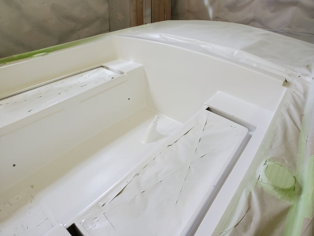
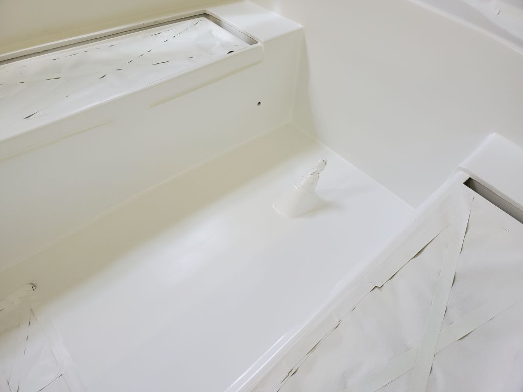
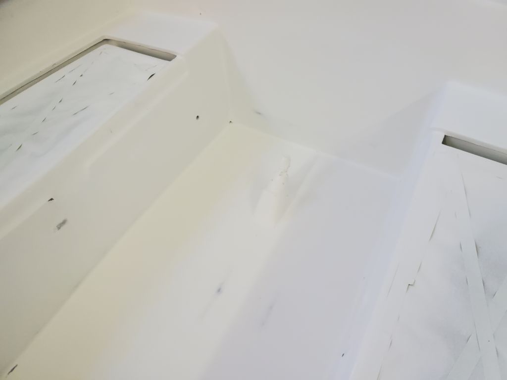
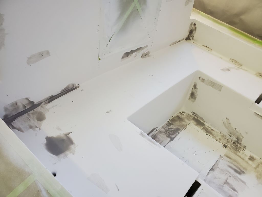
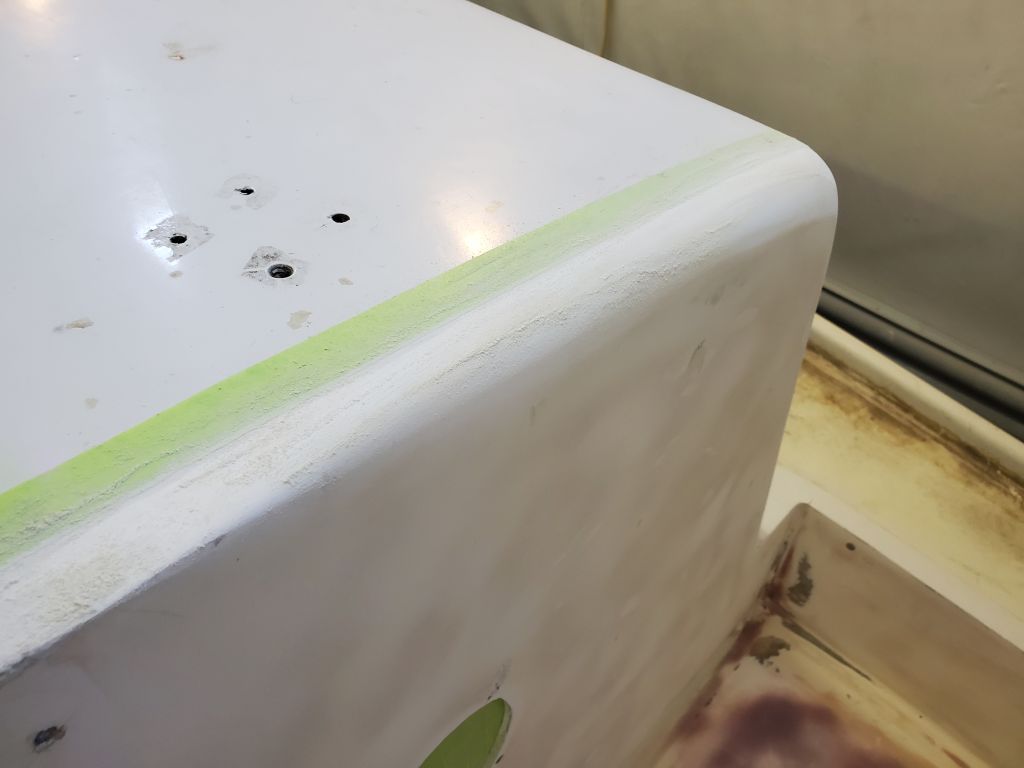
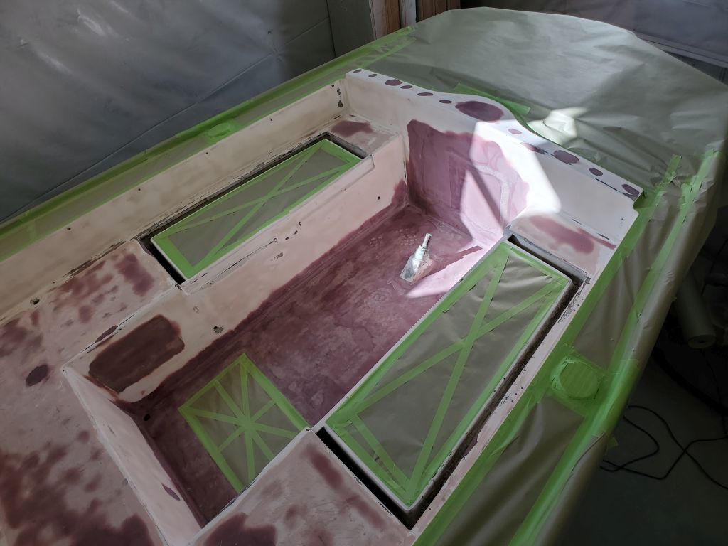
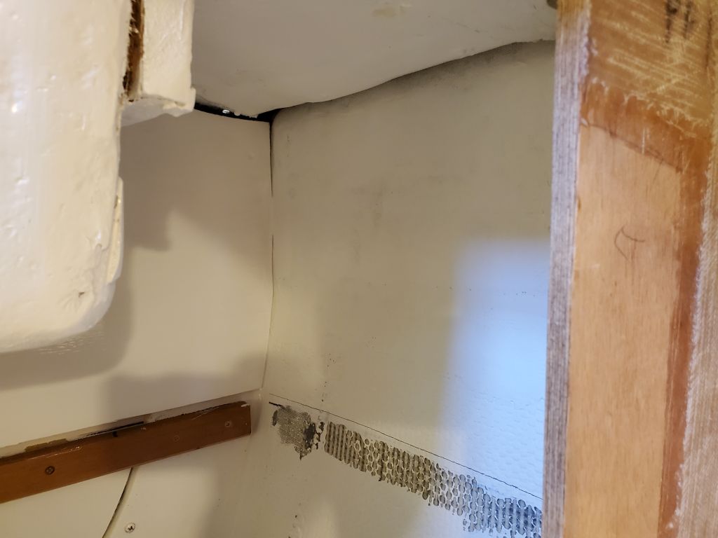
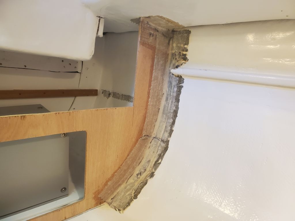
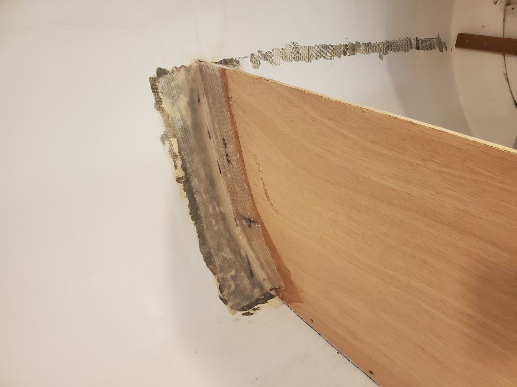
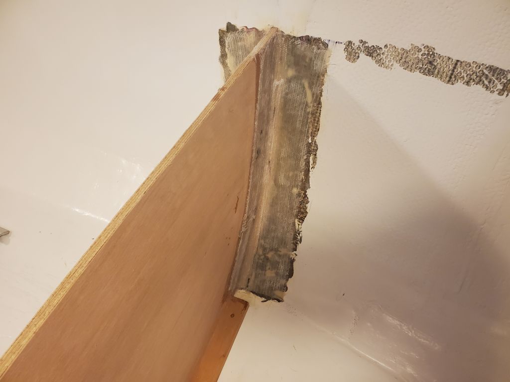
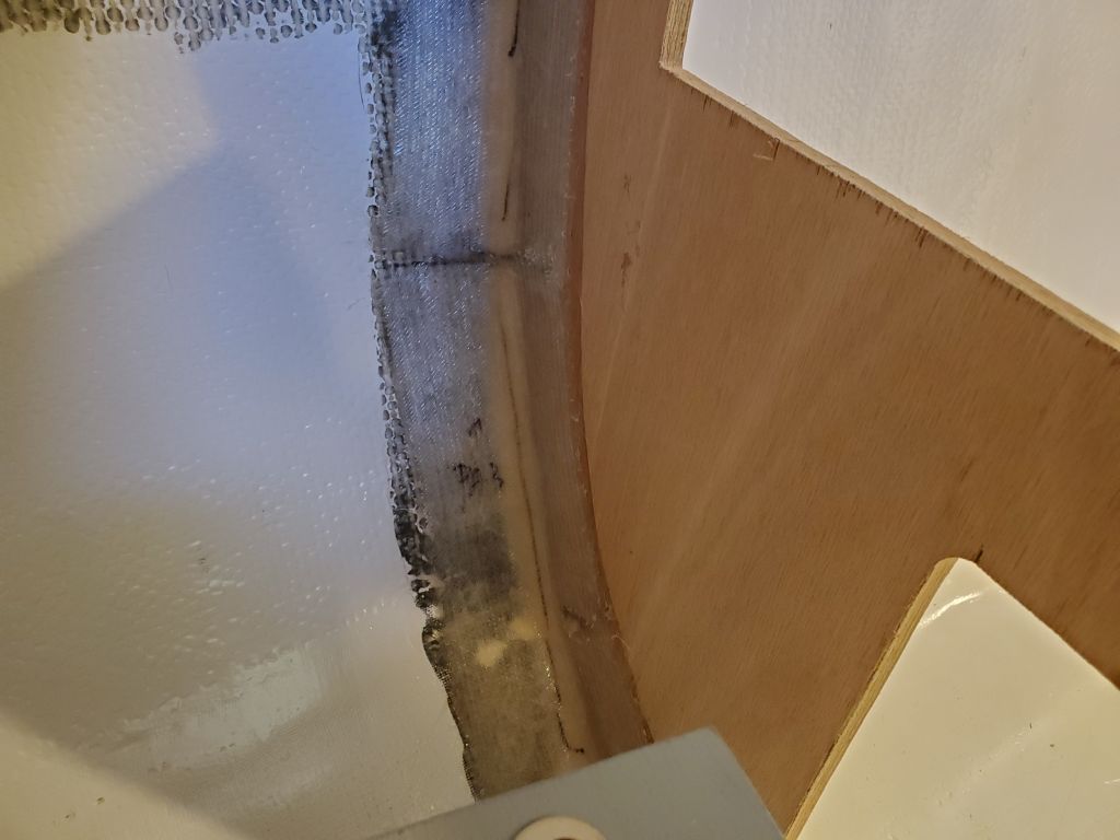
After a late-ish start following an errand, I finished up the new galley tabbing with a quick water wash and light hand sanding just to remove any sharp edges or nubs from the fresh fiberglass.

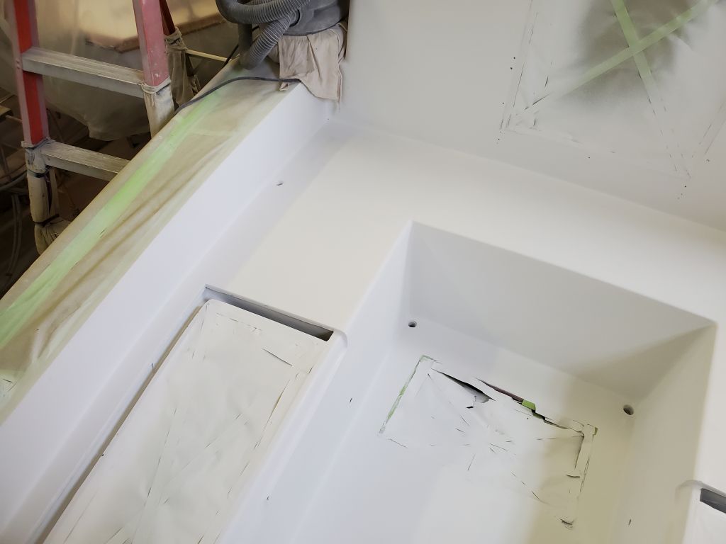
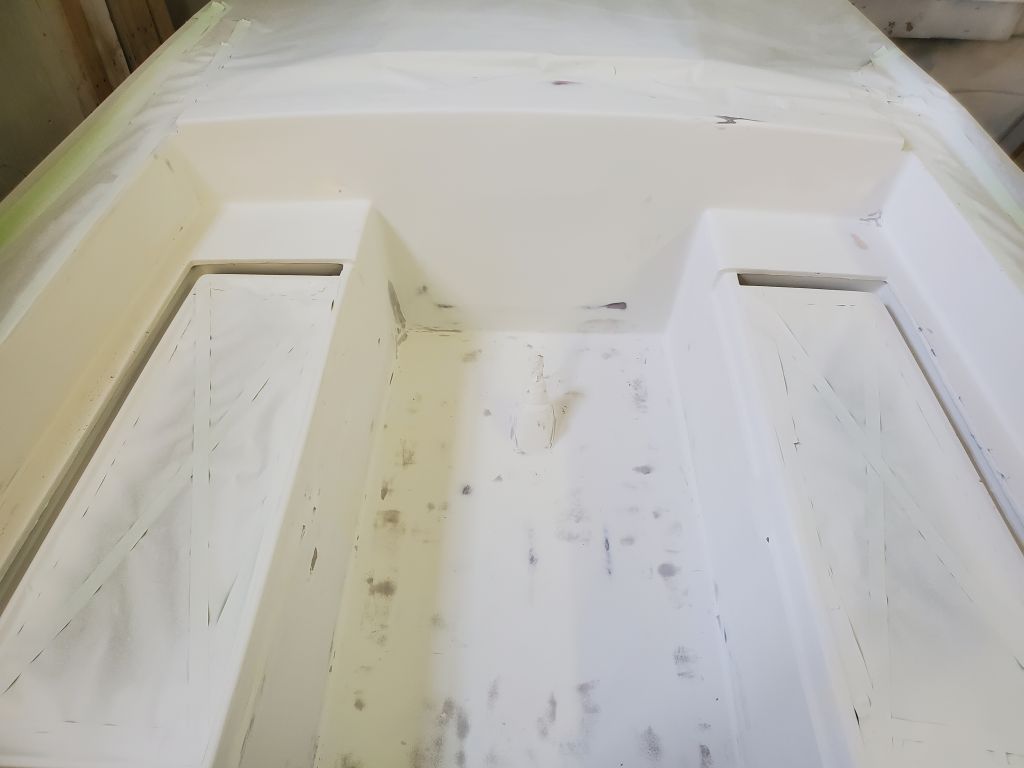
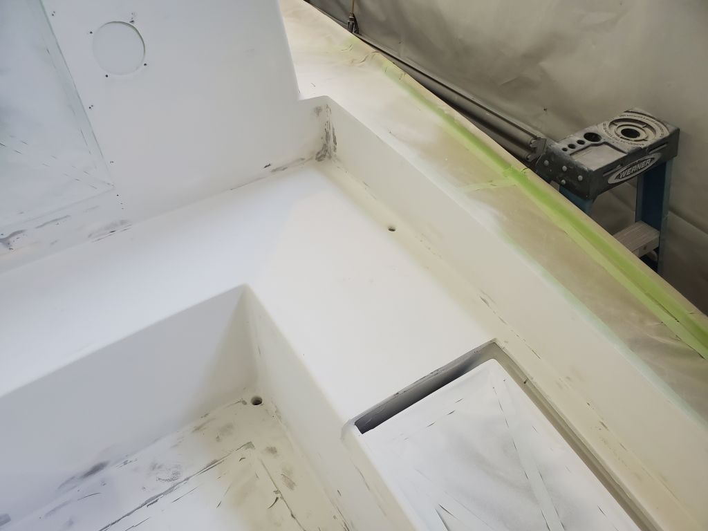
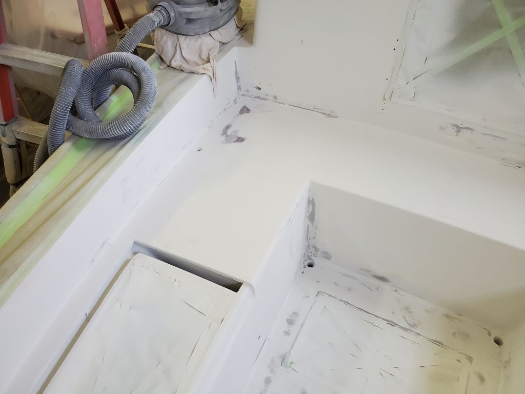
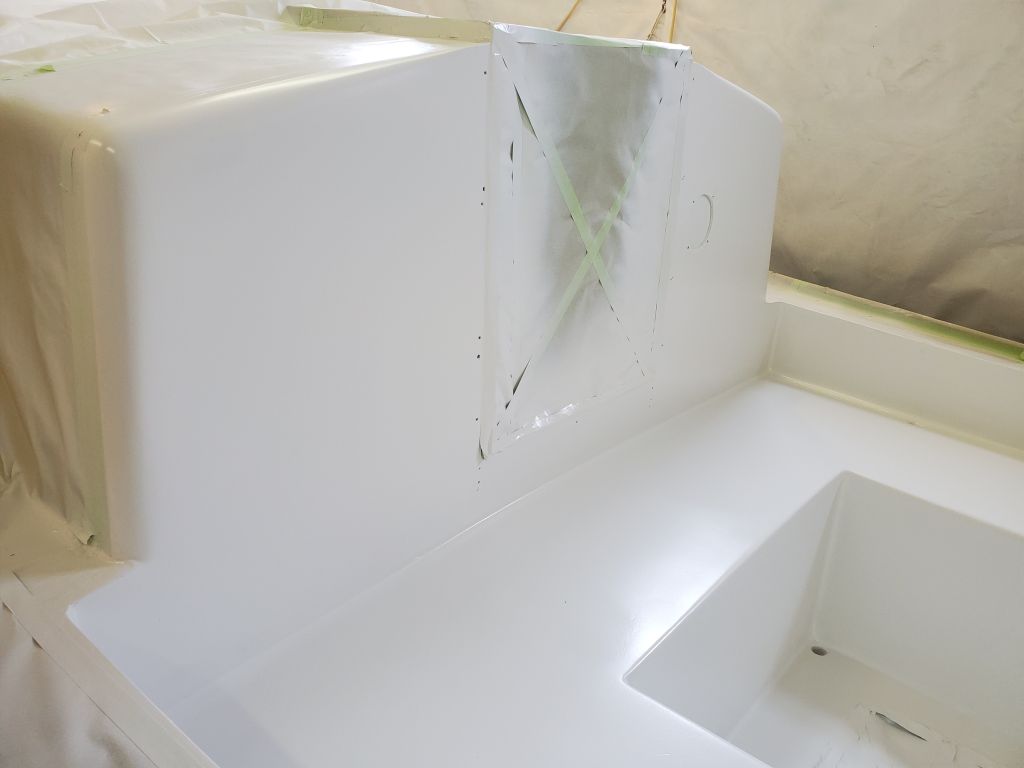
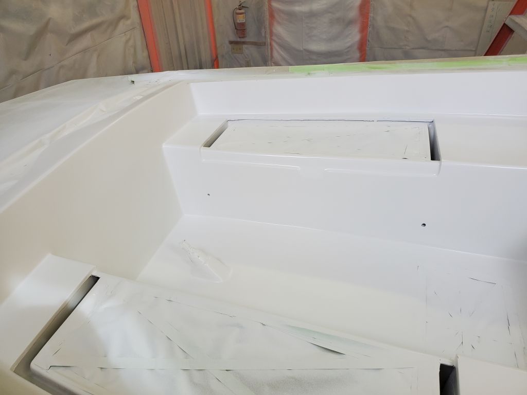
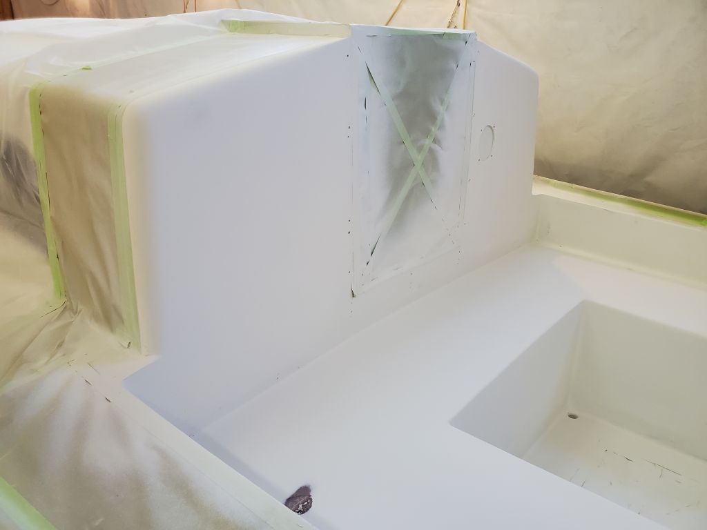
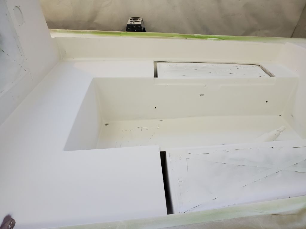
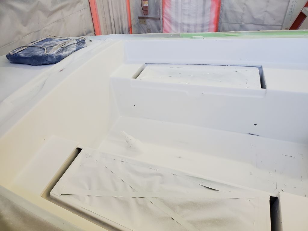
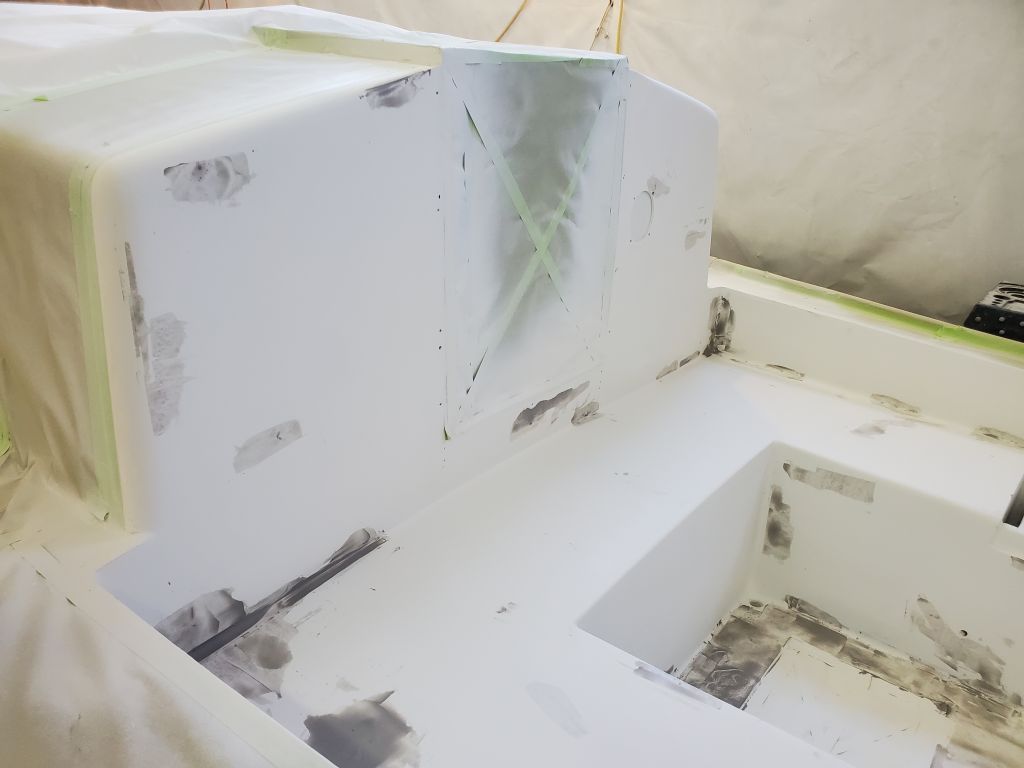
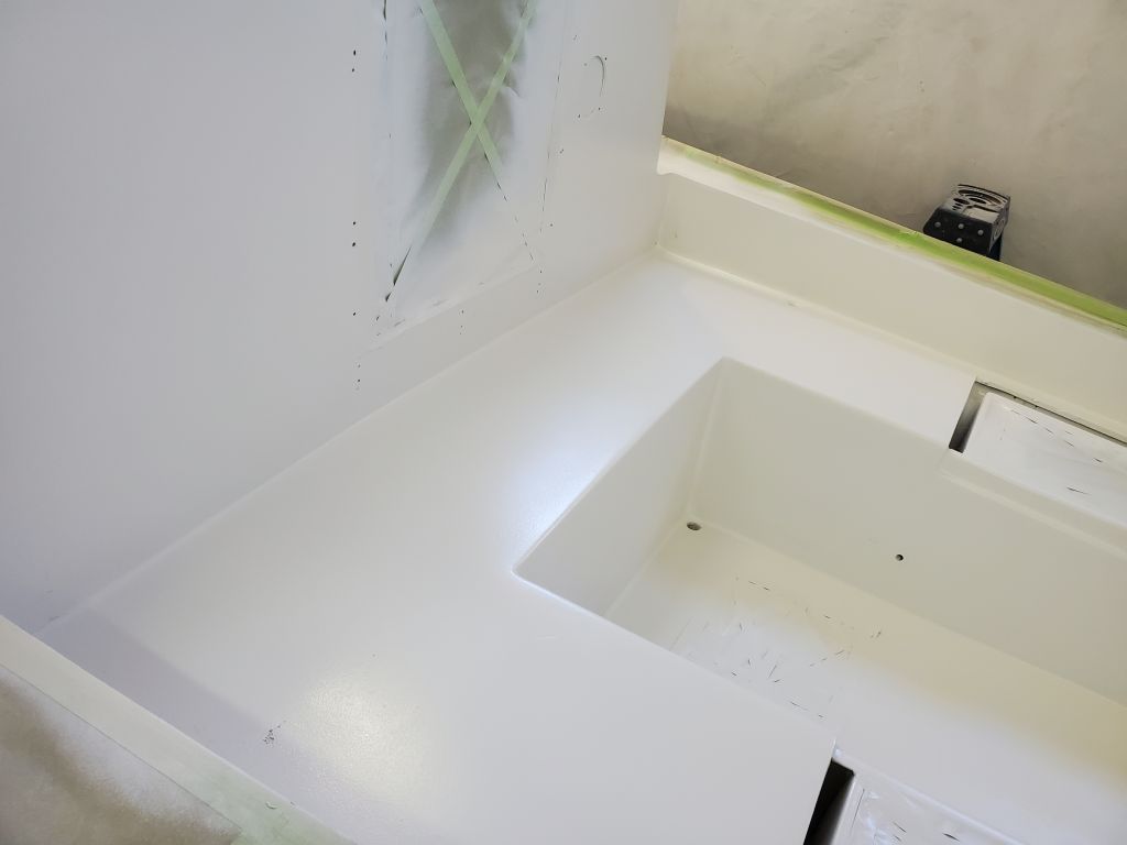
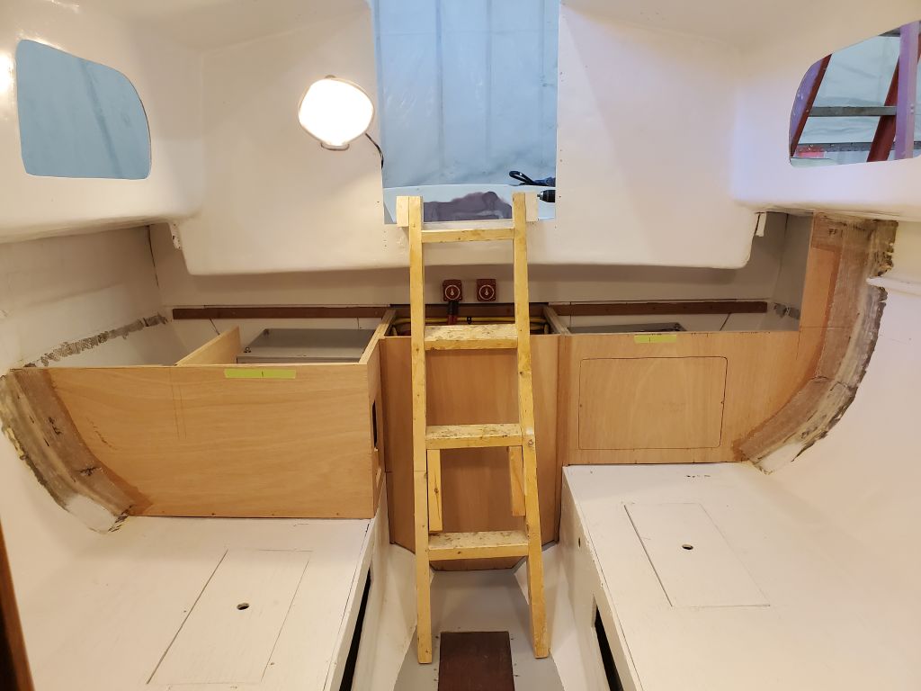
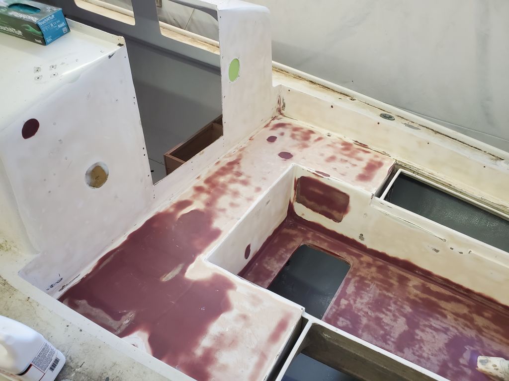
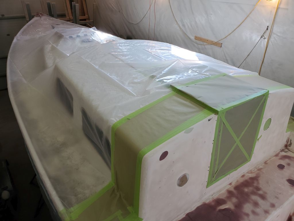
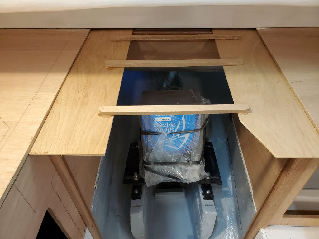
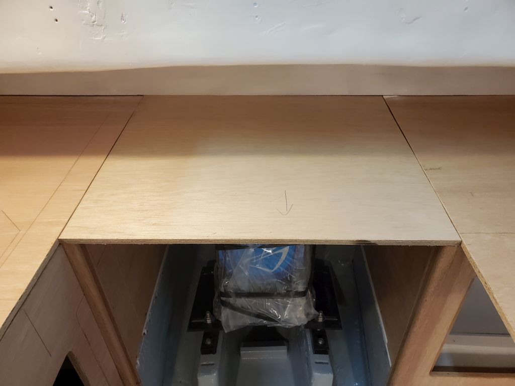
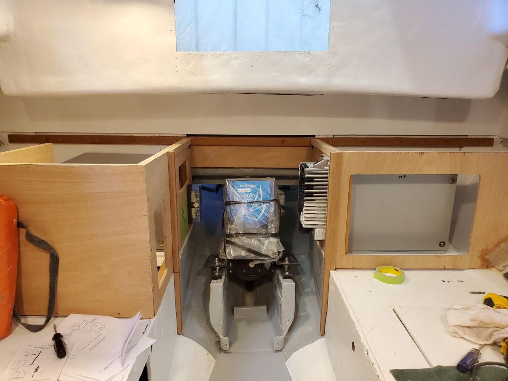
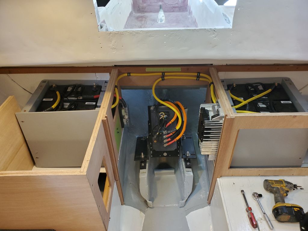
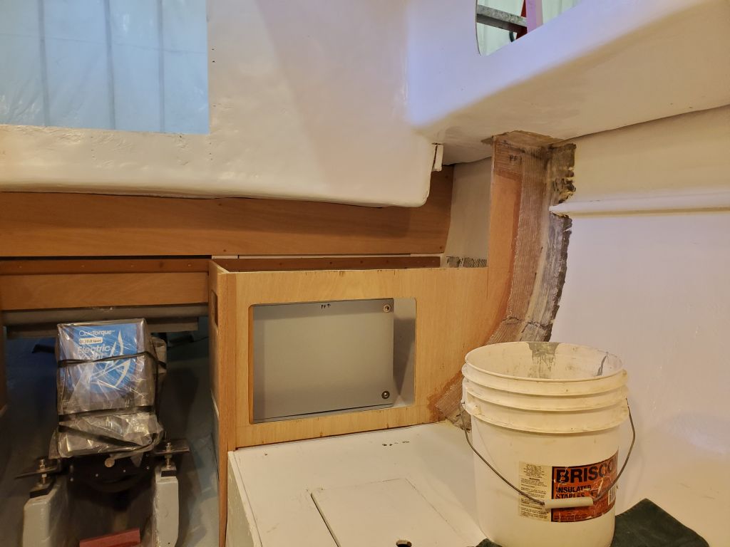
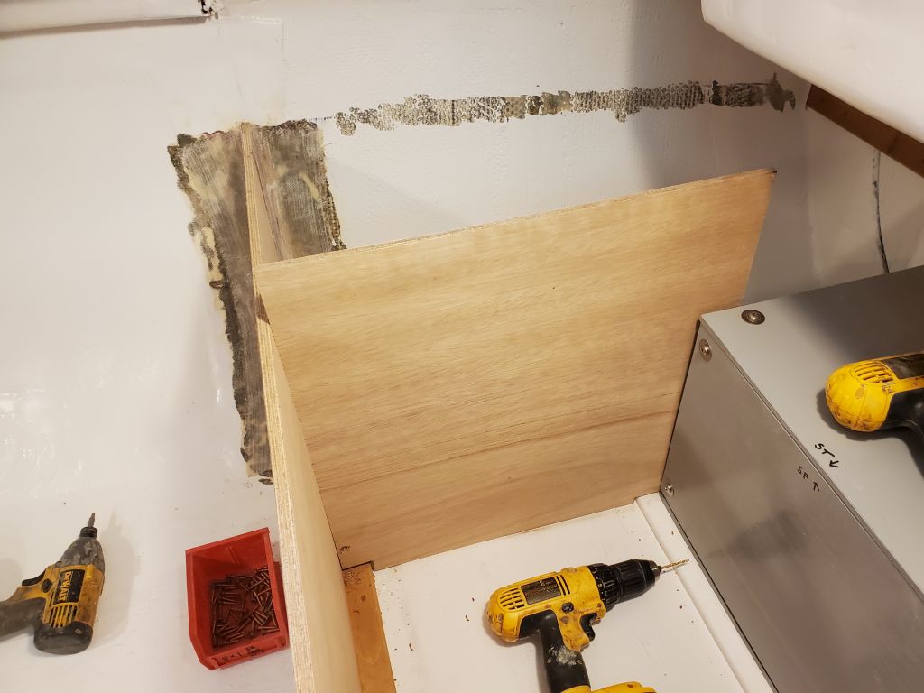
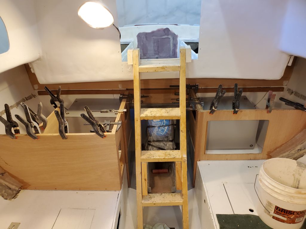
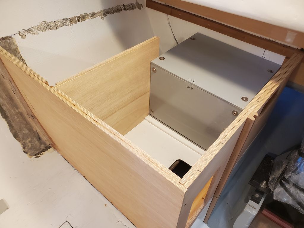
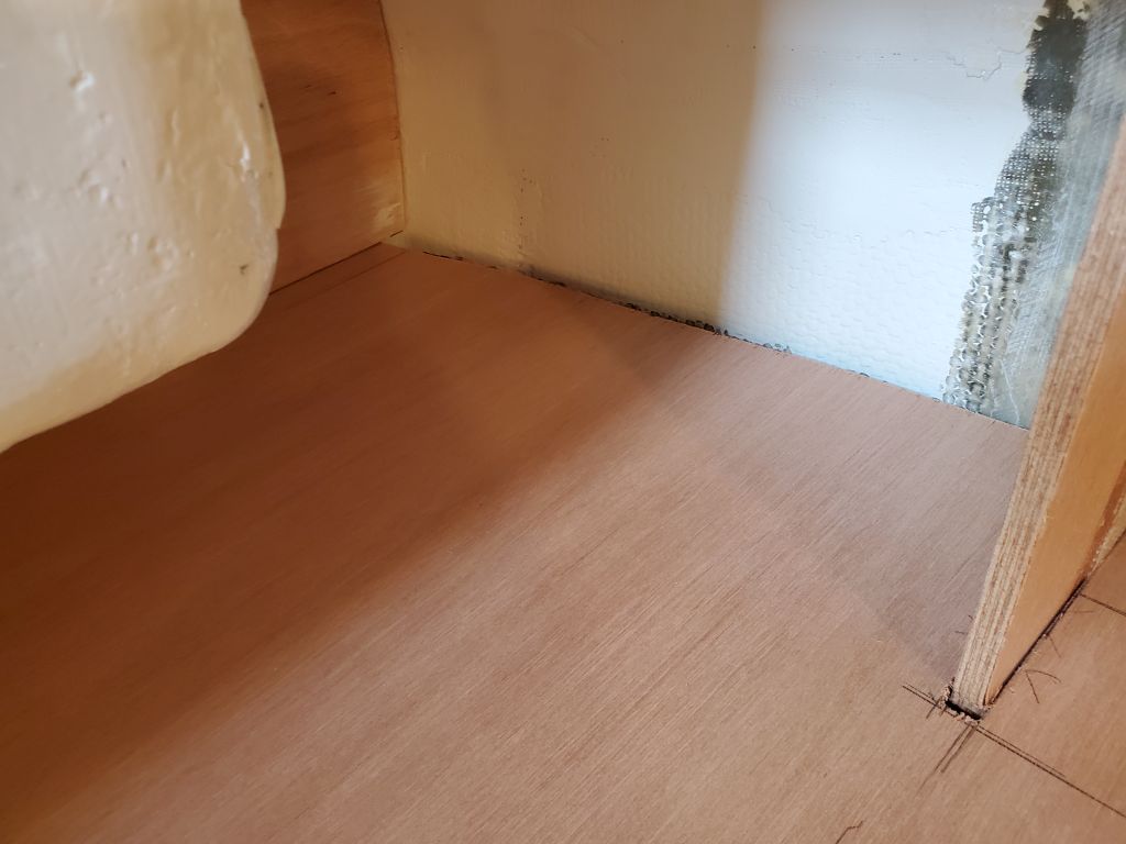
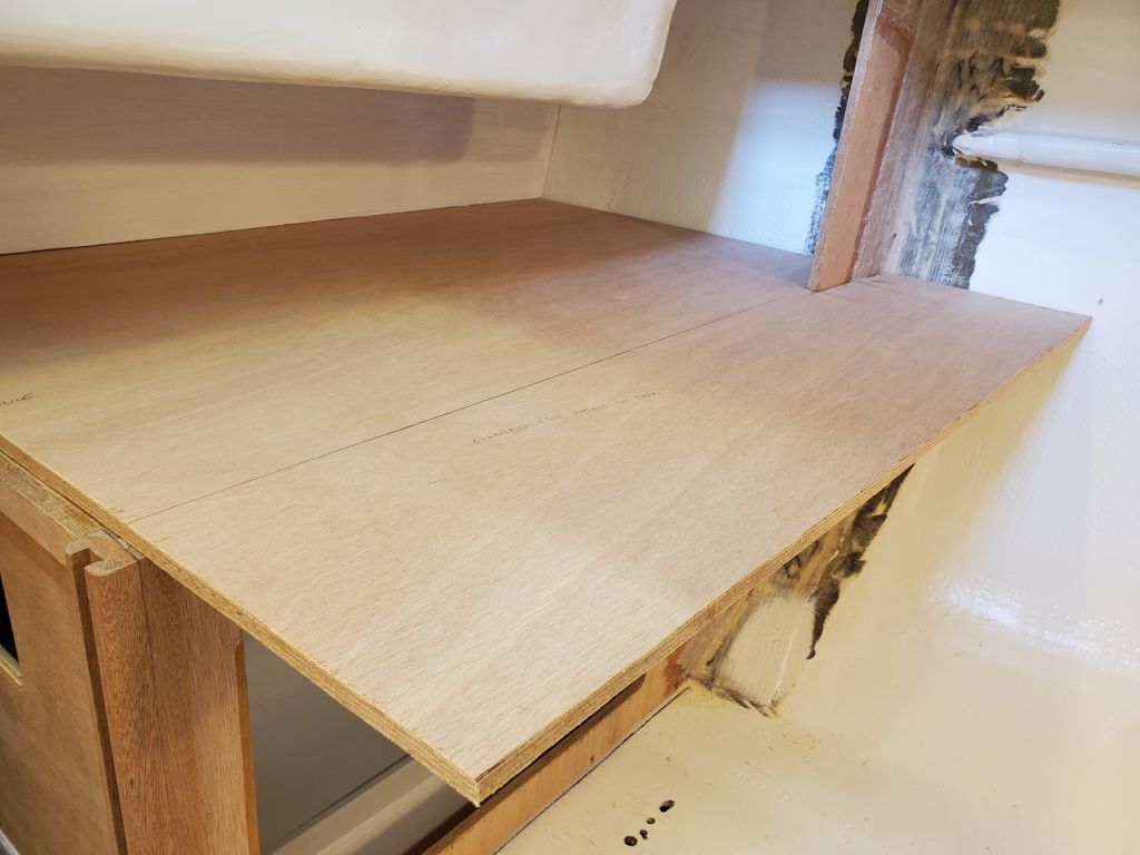
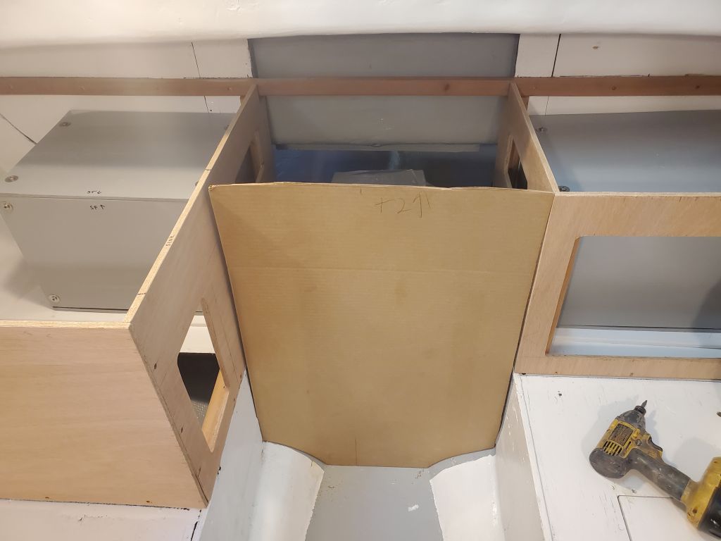
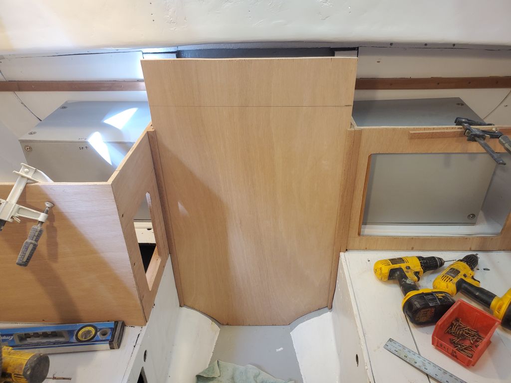
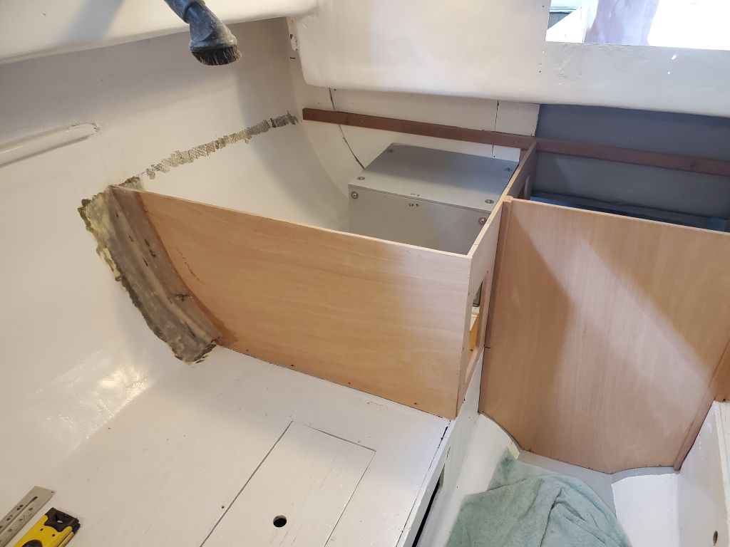
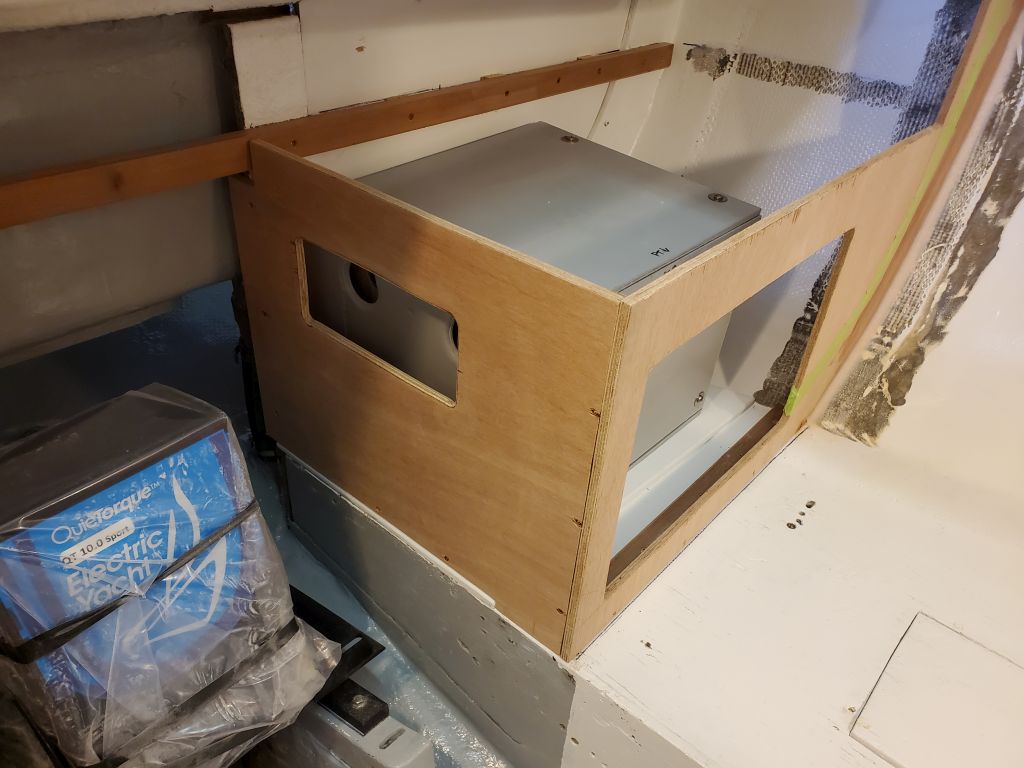
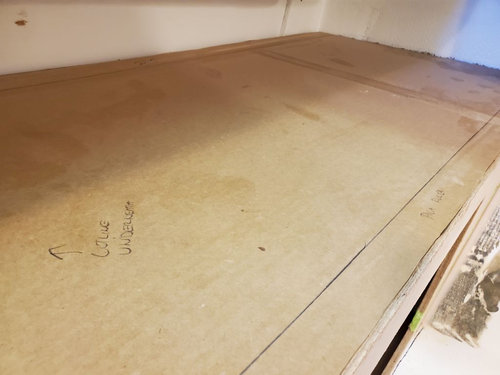
With the side galley cabinets and engine room defined, now I could build and finish up the front panel to the engine room, which would finish off the galley in the main and further define the mechanical space, which would be helpful as I transitioned into some of the wiring and related installations.  I used my original cardboard template/mockup to check the fit between the real cabinets and, finding it good enough for the purpose for now, proceeded with the final installation details and construction.

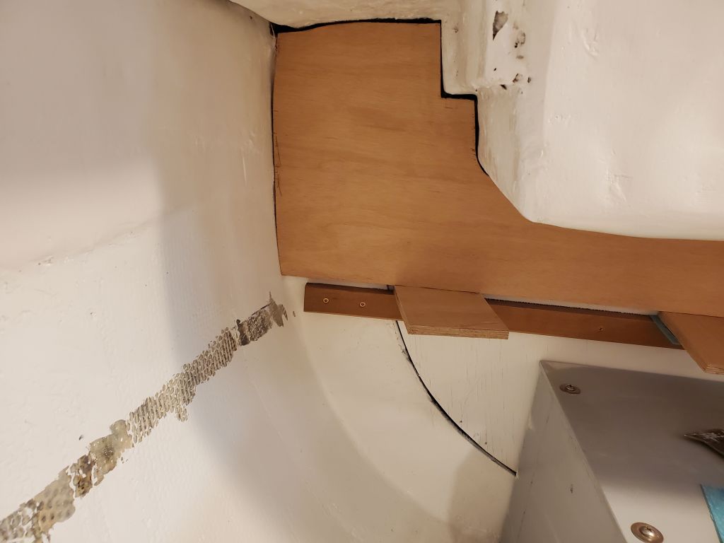
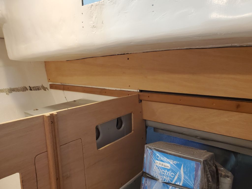
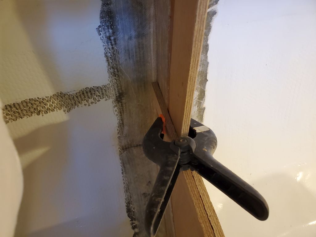
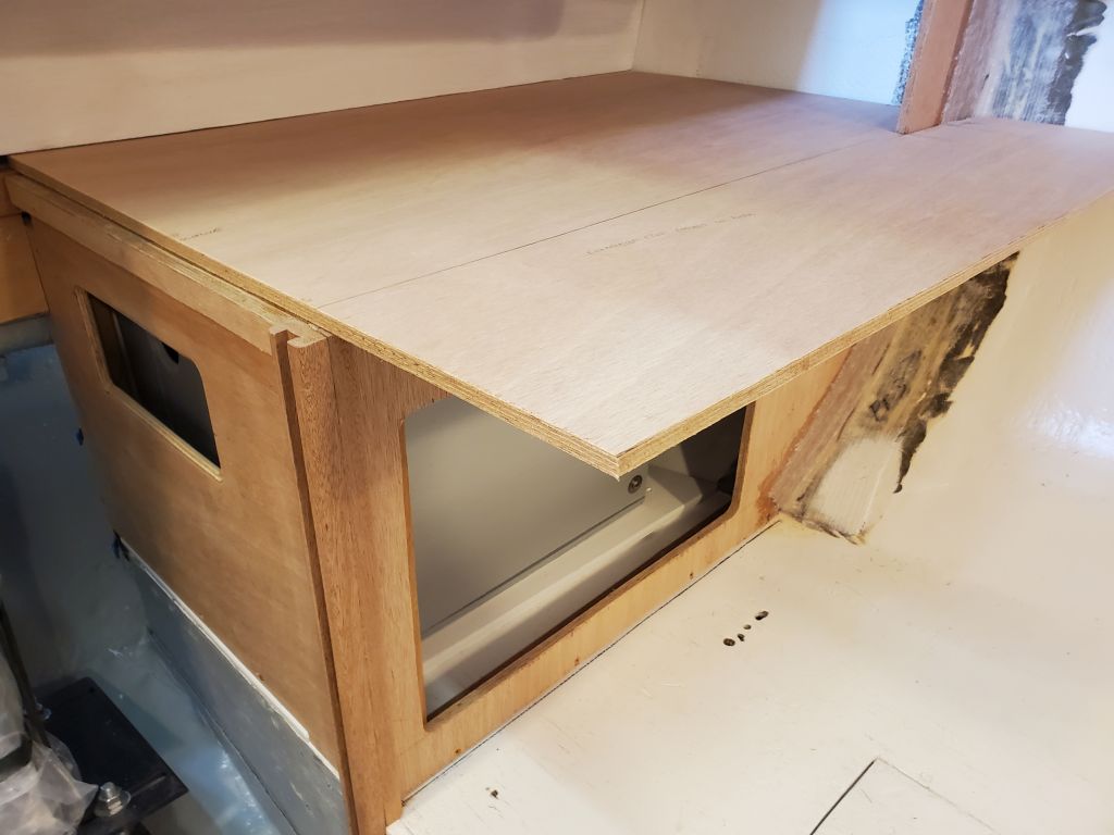
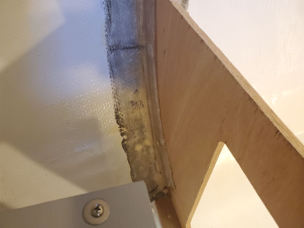
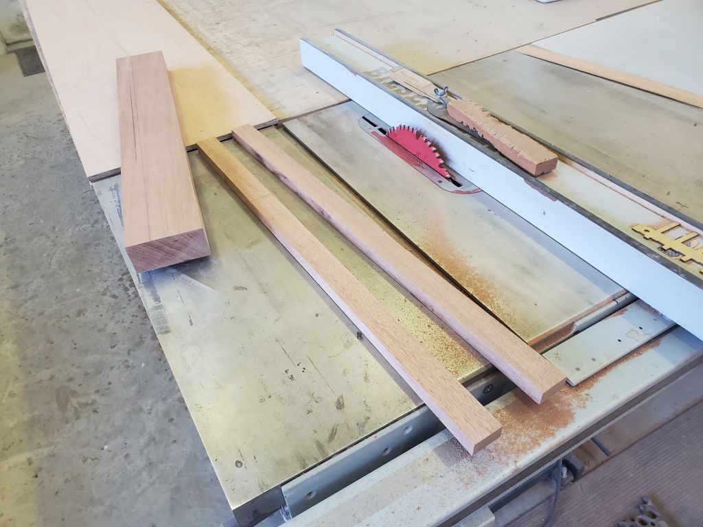
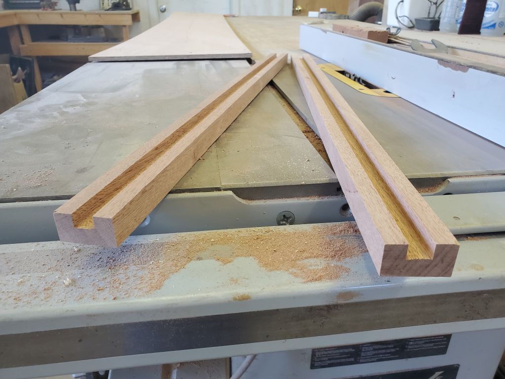
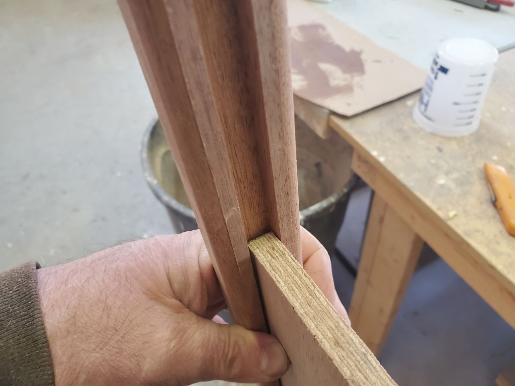
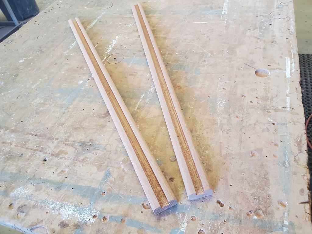
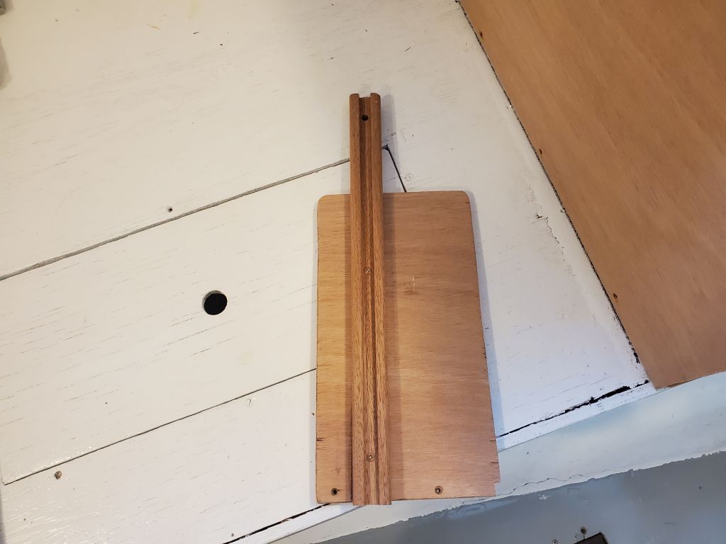
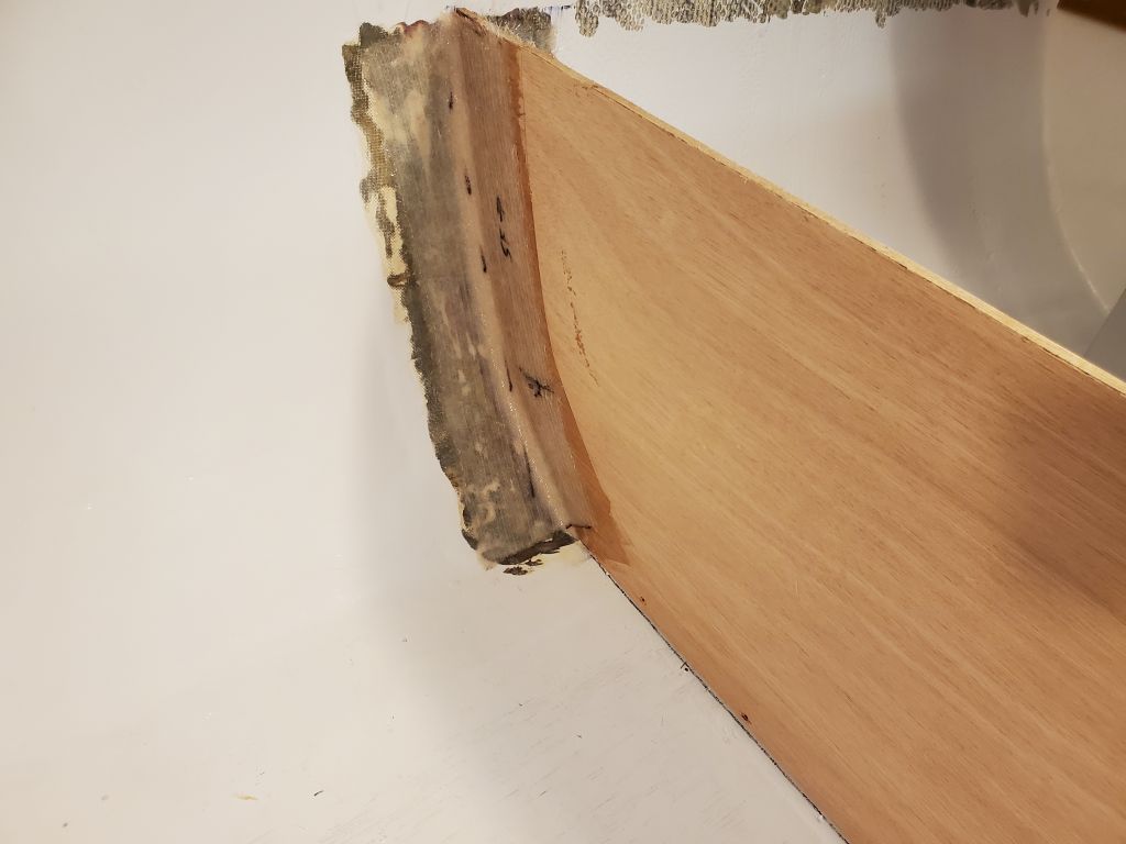
To position and secure the front panel, allowing for easy removal, I chose to build simple channels for each side, into which the panel would slide and by which would be held.  From some of the available stock of Sipo, I milled two blanks 1-1/2″ wide (allowing for a 1/2″ wide dado to accommodate the plywood, plus 1/2″ on each side) and 3/4″ thick, and long enough to span the height and then some.  I milled 3/8″ deep by roughly 1/2″ wide dados through the centers of the strips, which held the 12mm plywood securely, but not tightly to allow for ease of installation and removal.  To finish off the pieces, I rounded the outer corners and sanded them smooth.

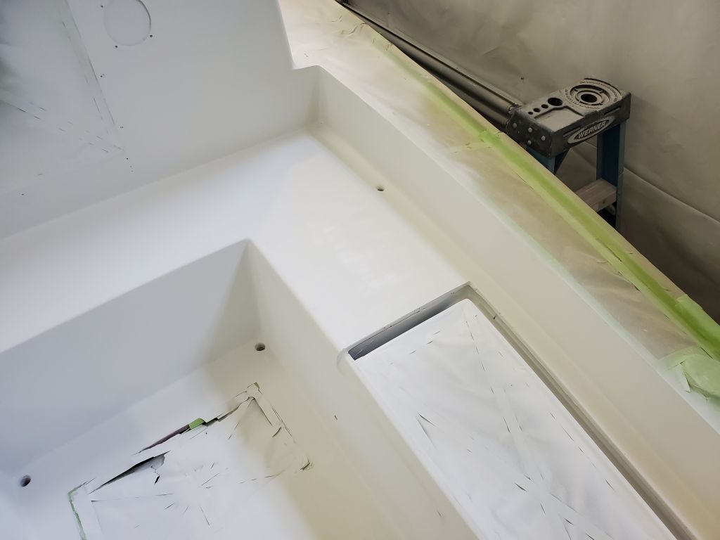
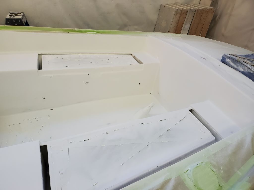
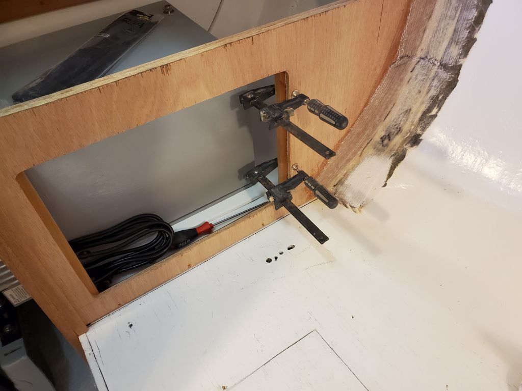
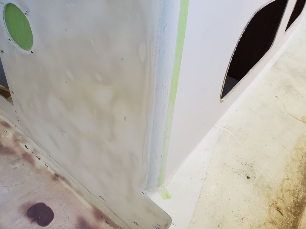
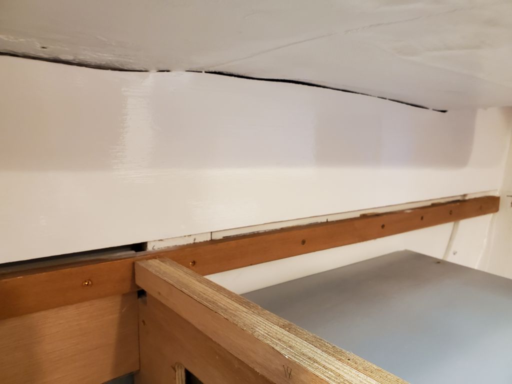
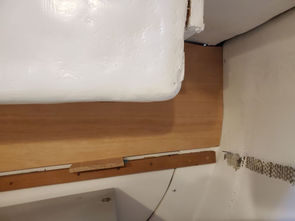
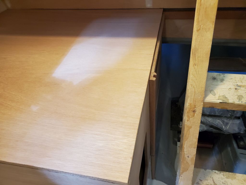
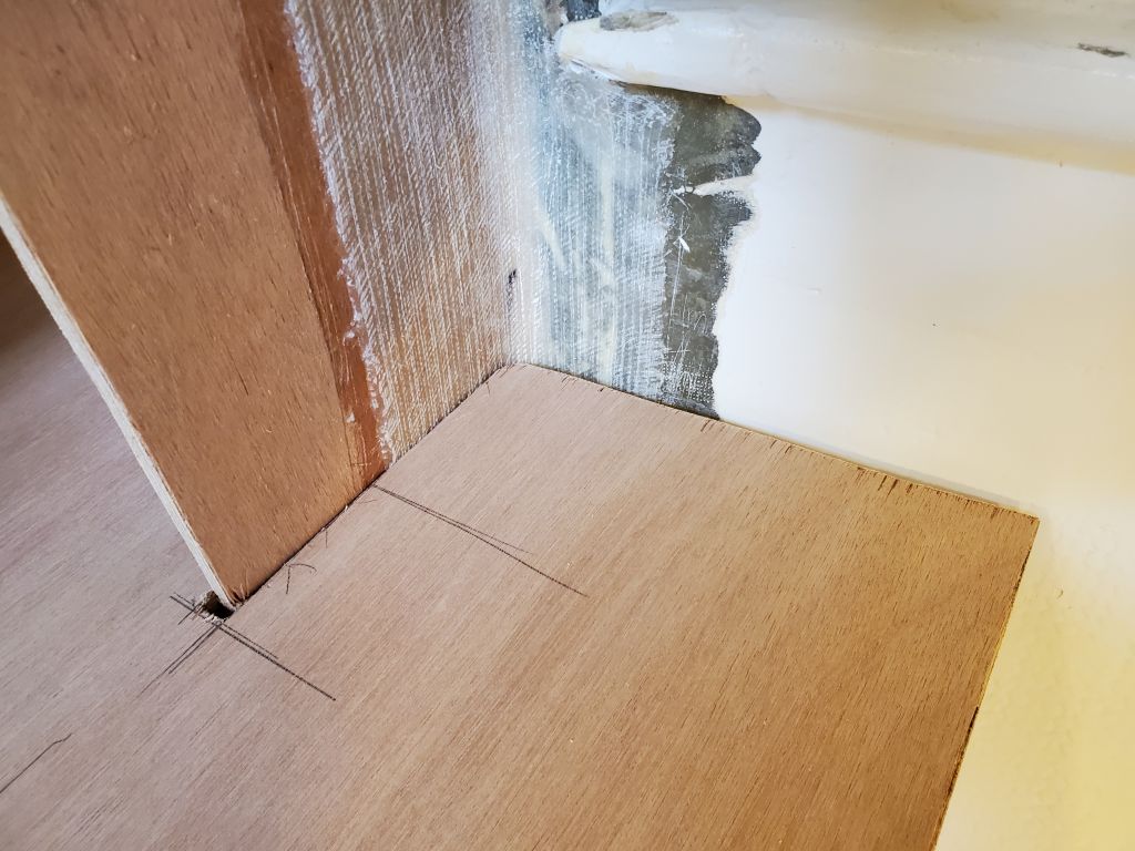
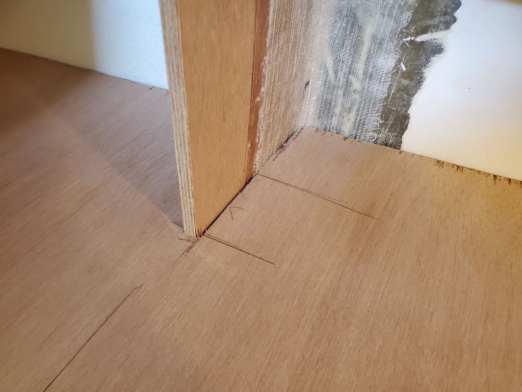
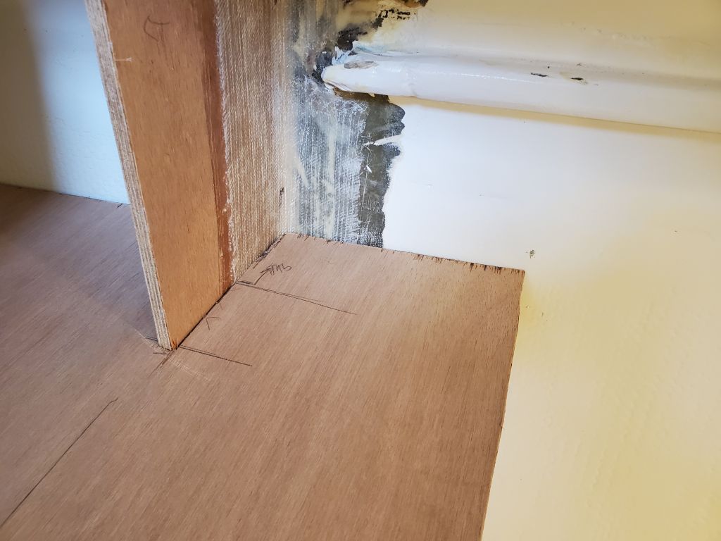
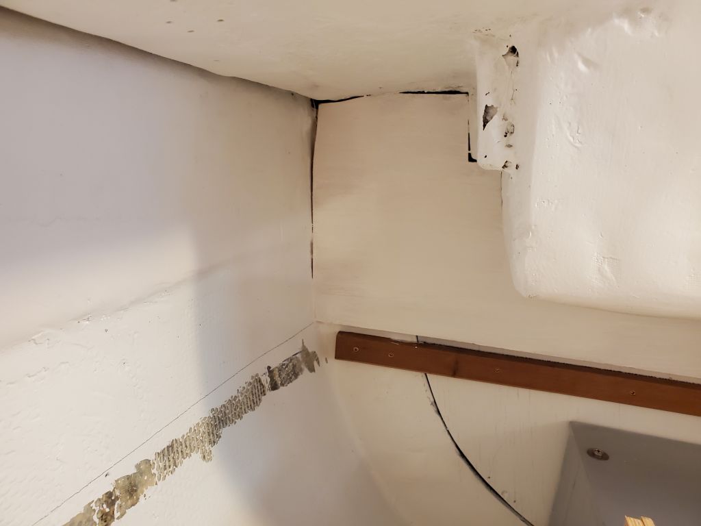
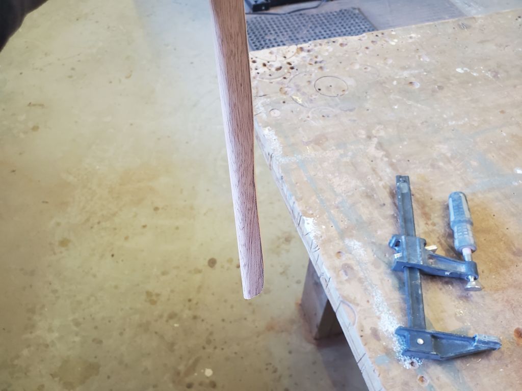
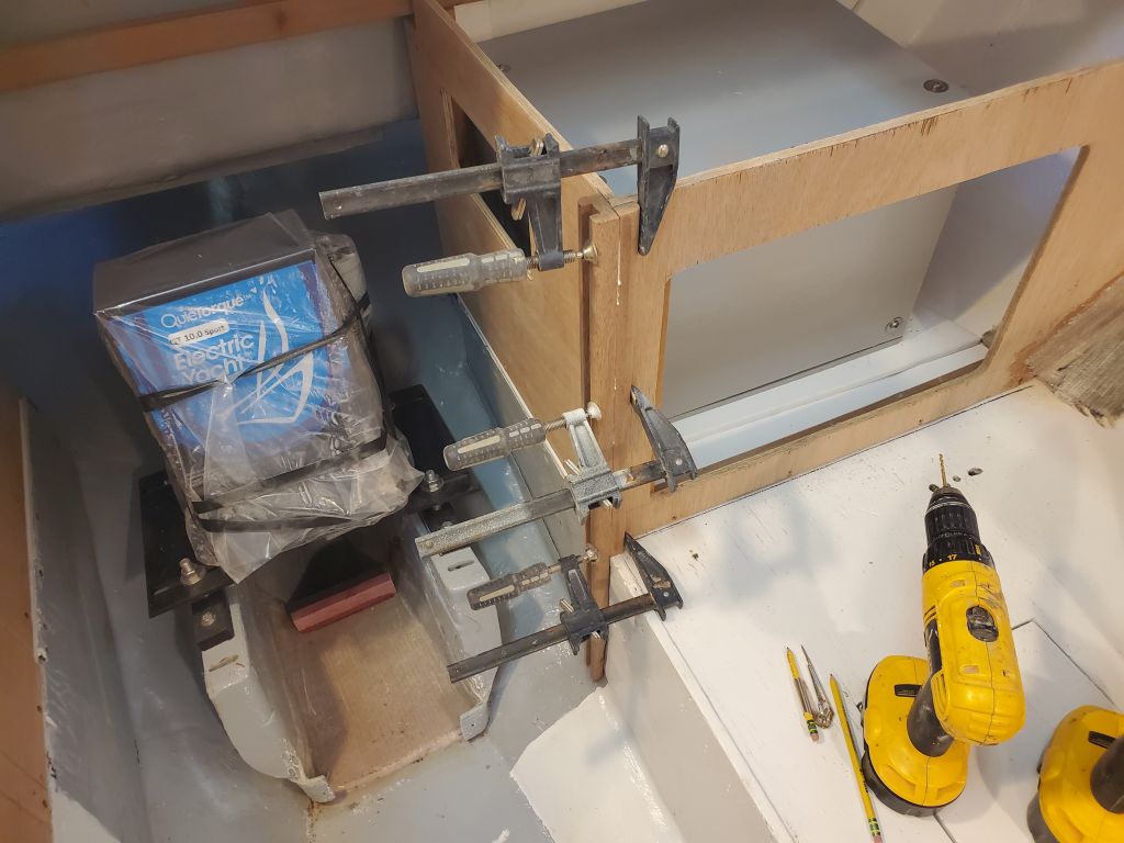
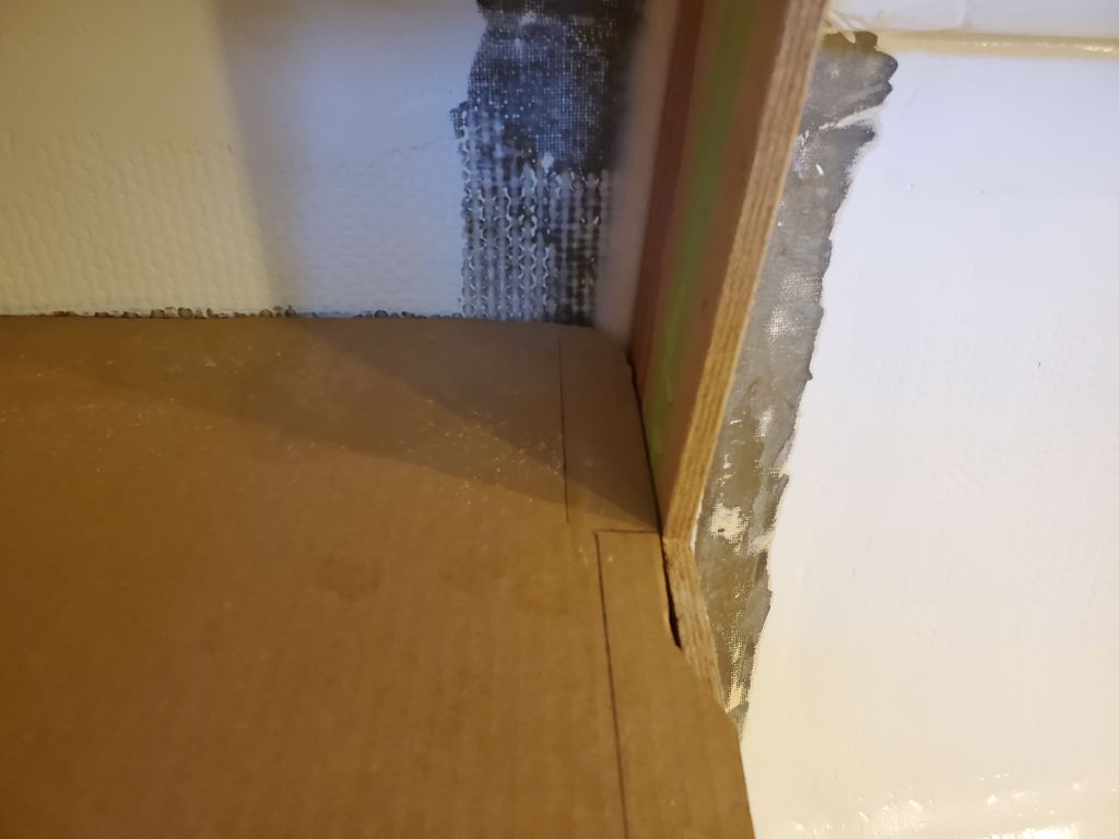
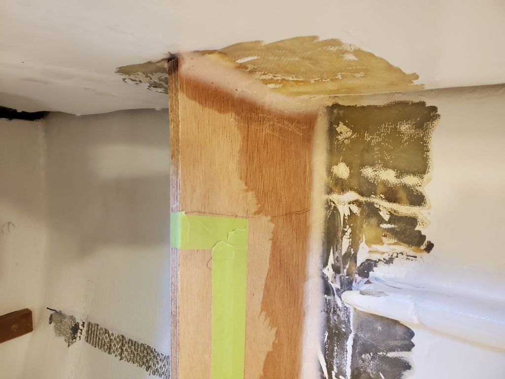
In all-new construction, installation would have been quick and simple, but here I found it to be fussier than expected, since the stiles needed to run on and between both the new, generally straight and true cabinetry in the galley, and the older, less-so original settees and tabbing at the bottom edge.  For the panel to work properly, the grooved stiles needed to be basically straight and plumb, and it required several rounds of scribing and shaping and fitting along the bottom few inches before I got the stile to fit acceptably over its whole length.  I secured it for now with screws and glue through the dado into the cabinetry behind, with the groove aligned with the front of the adjacent cabinet.

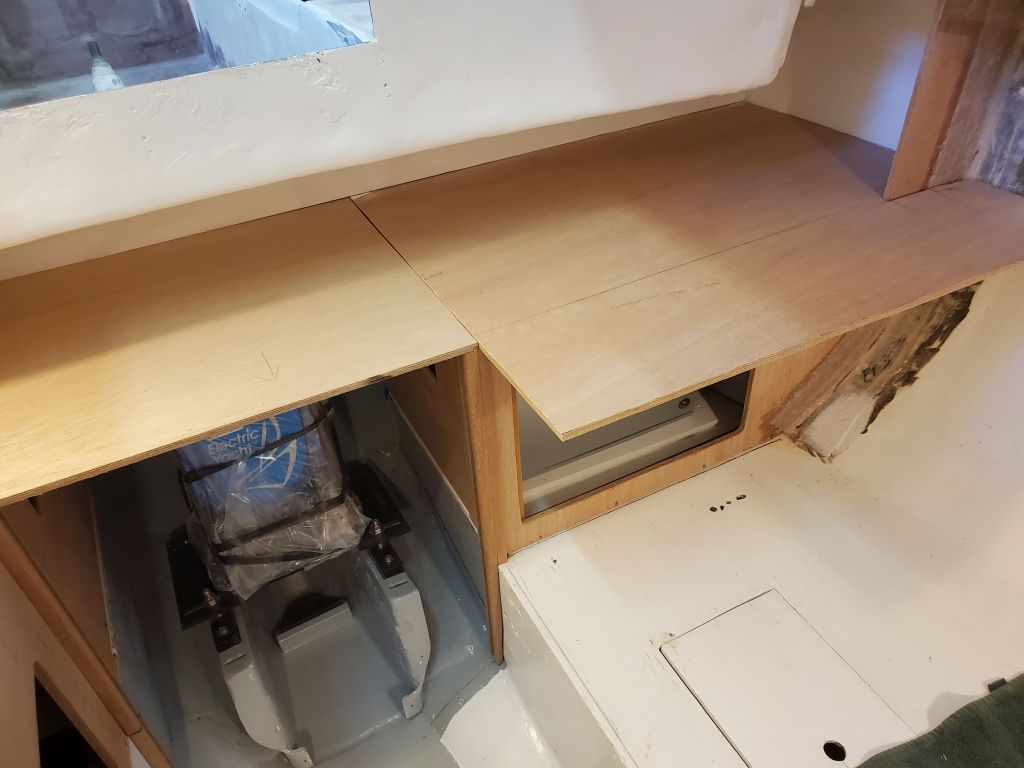
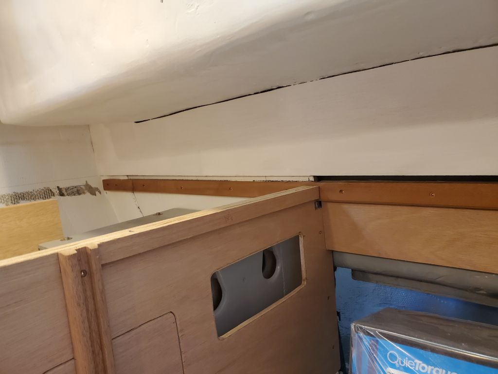
This let the stile overhang the front of the port cabinet by about 1/2″, and although at the onset I’d considered making a trim that would incorporate a little return onto the cabinet to finish off this overhanging edge (while also hiding the joint in the plywood), this would have turned into a highly fussy and difficult thing, so instead I added a second piece of the mahogany to finish off the corner, gluing it to the stile during its final installation (which was a bit later on in the process).

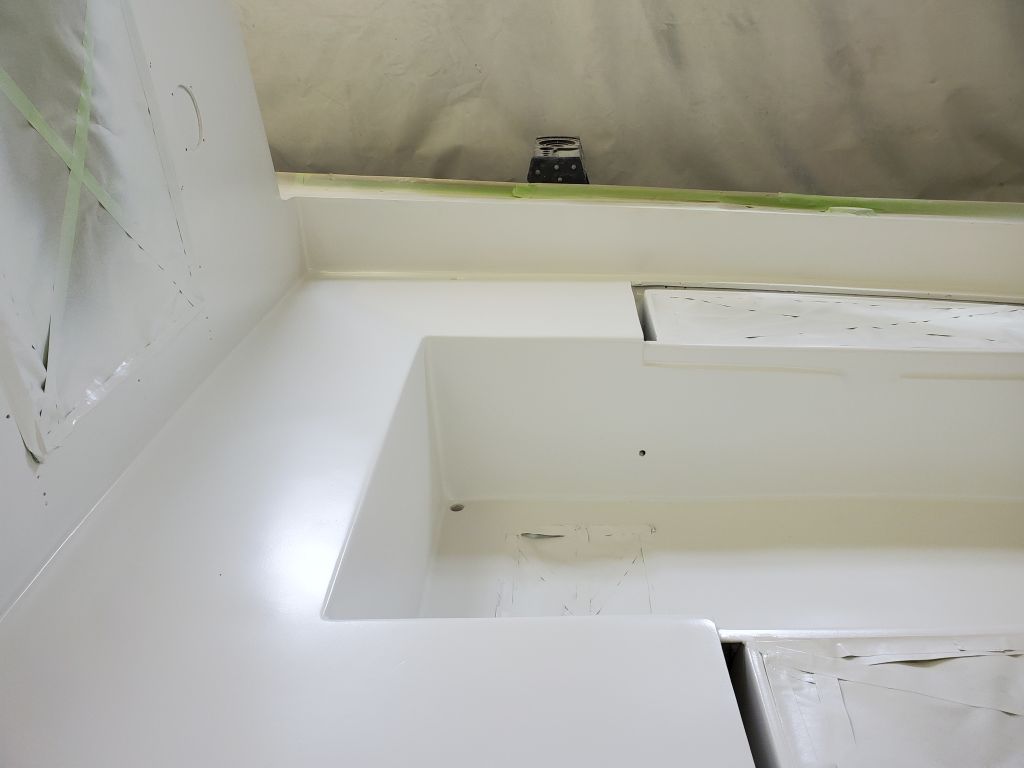
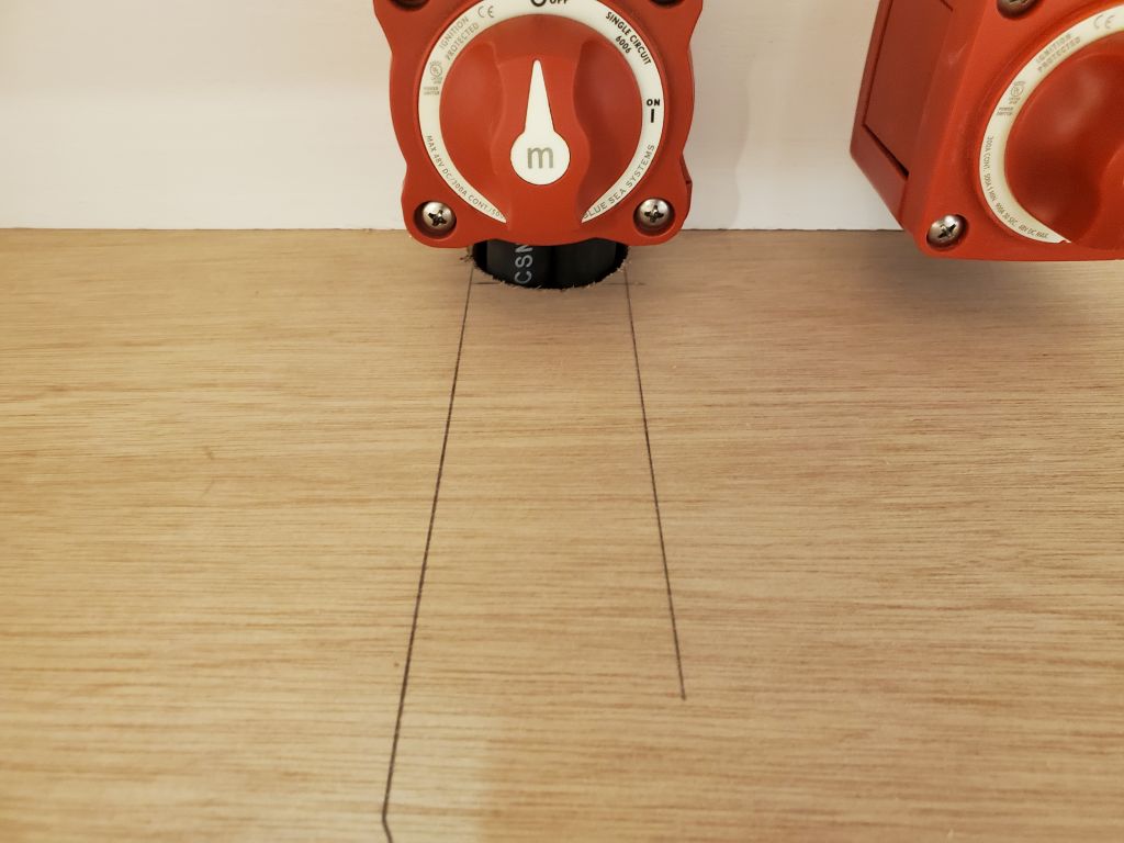
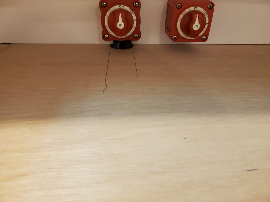
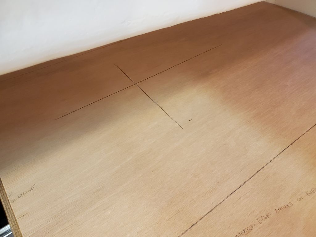
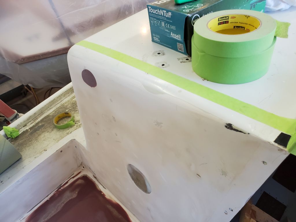
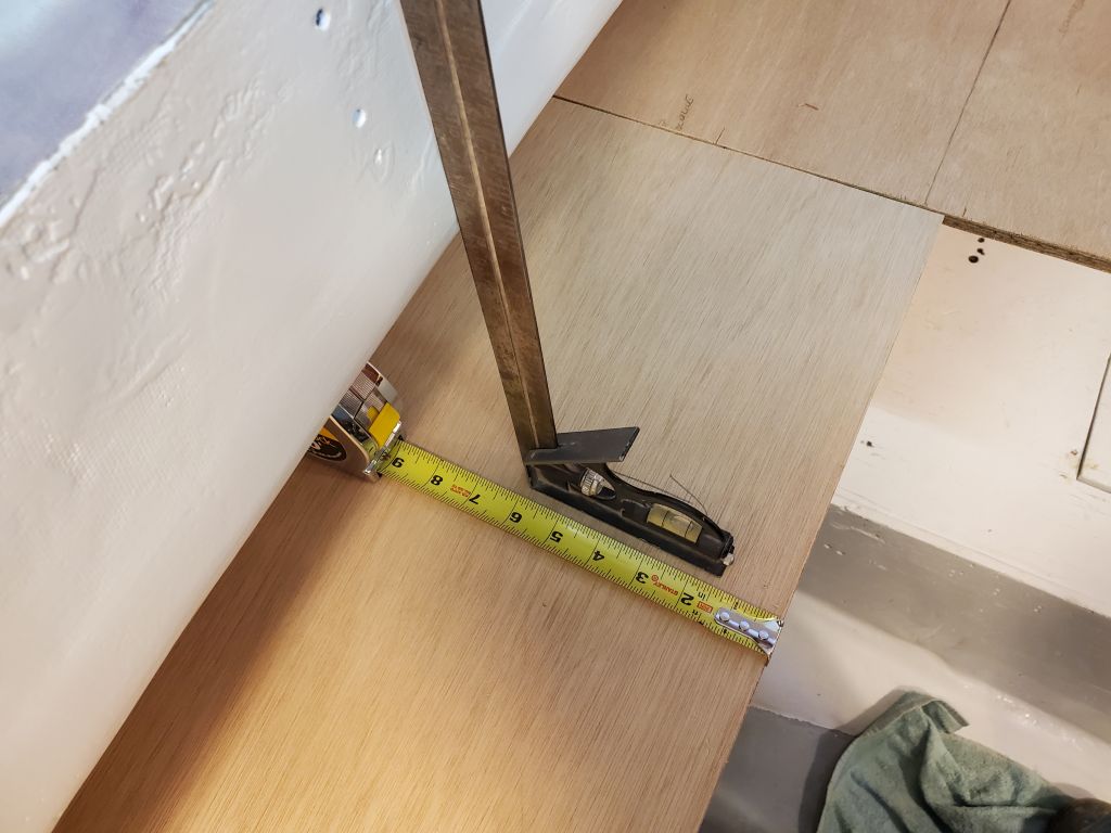
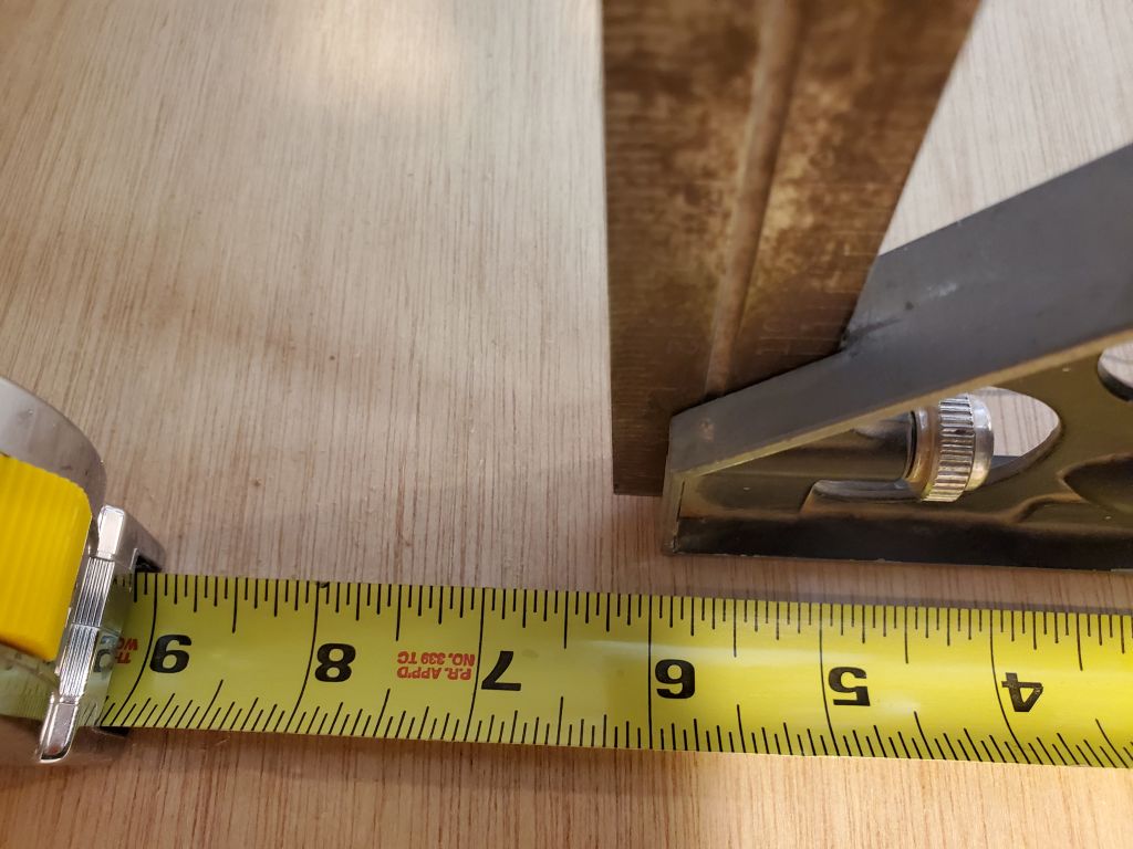
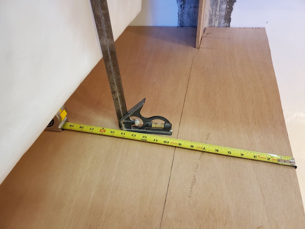
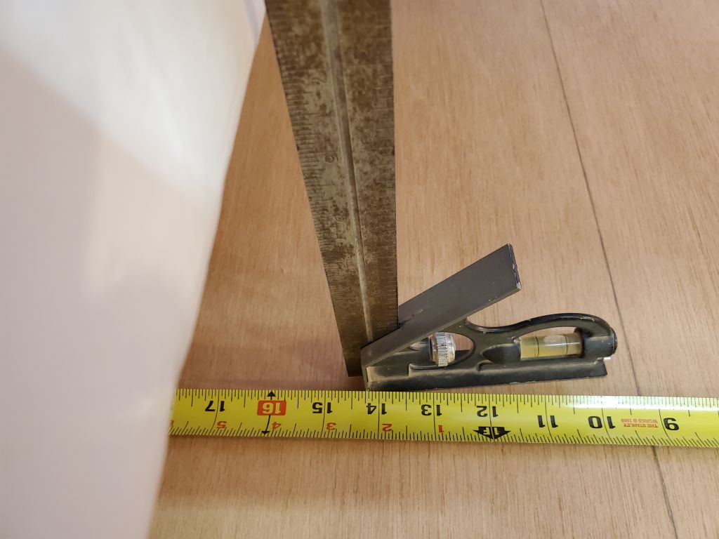
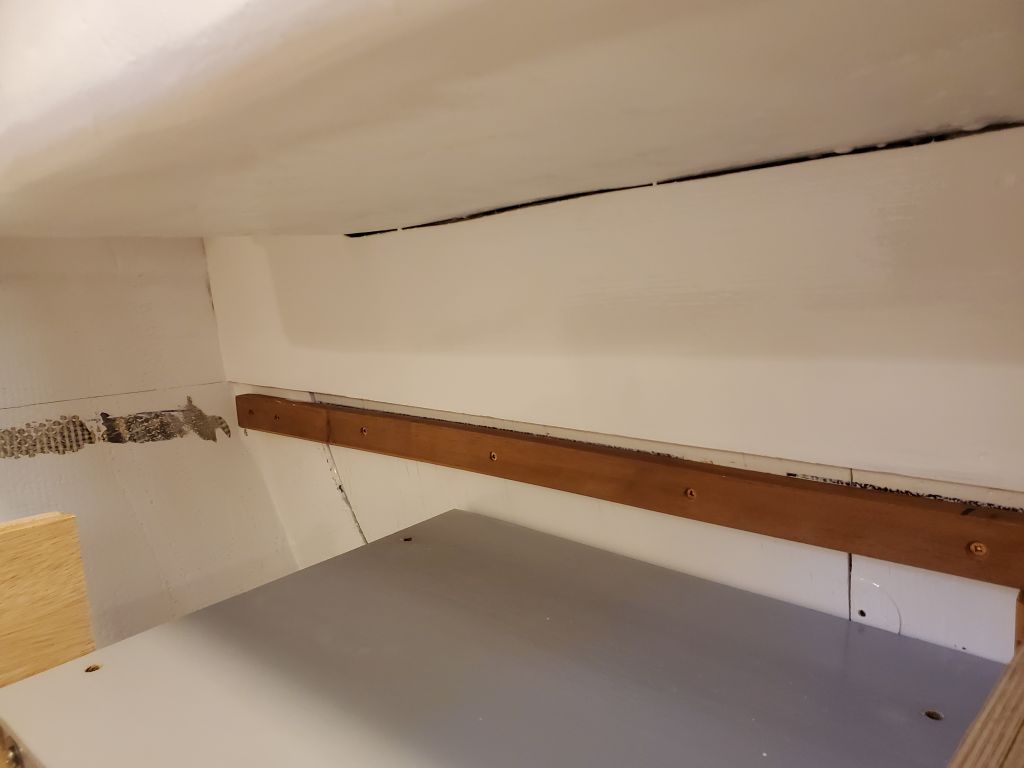
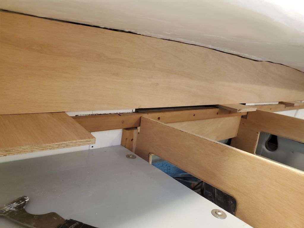
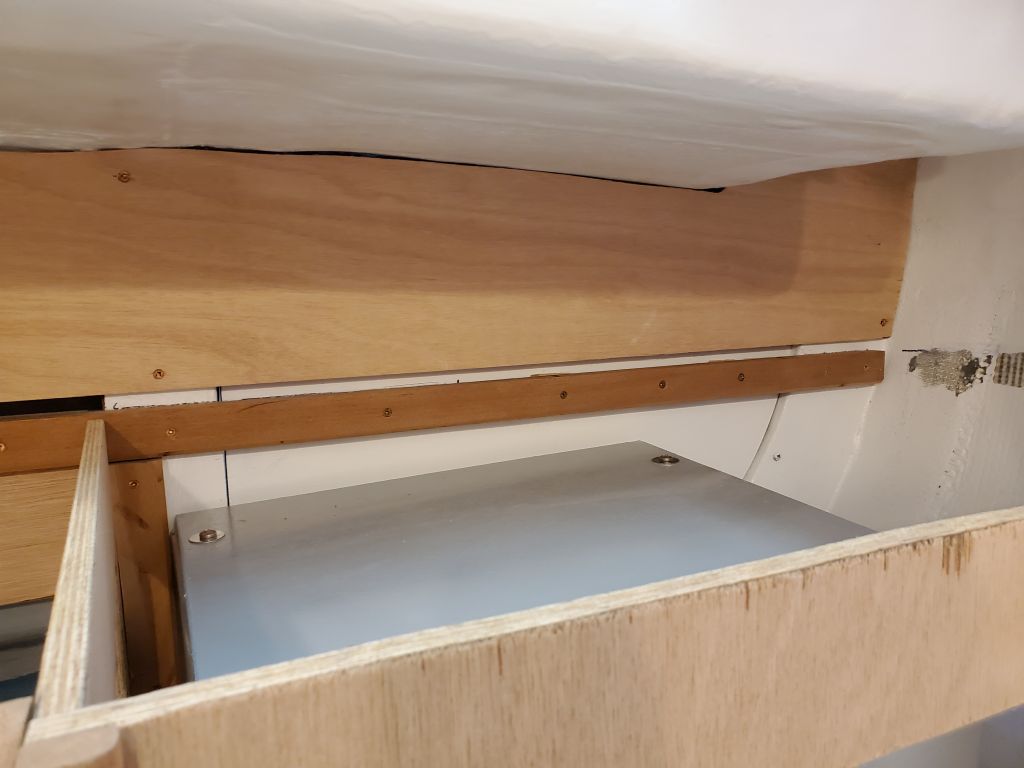
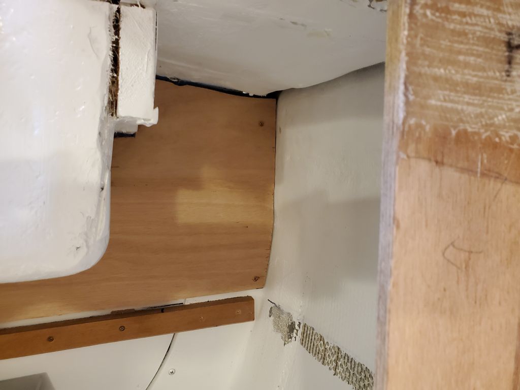
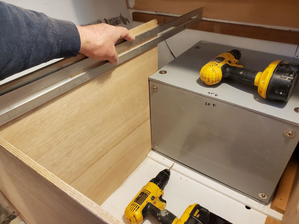
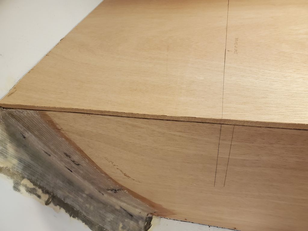
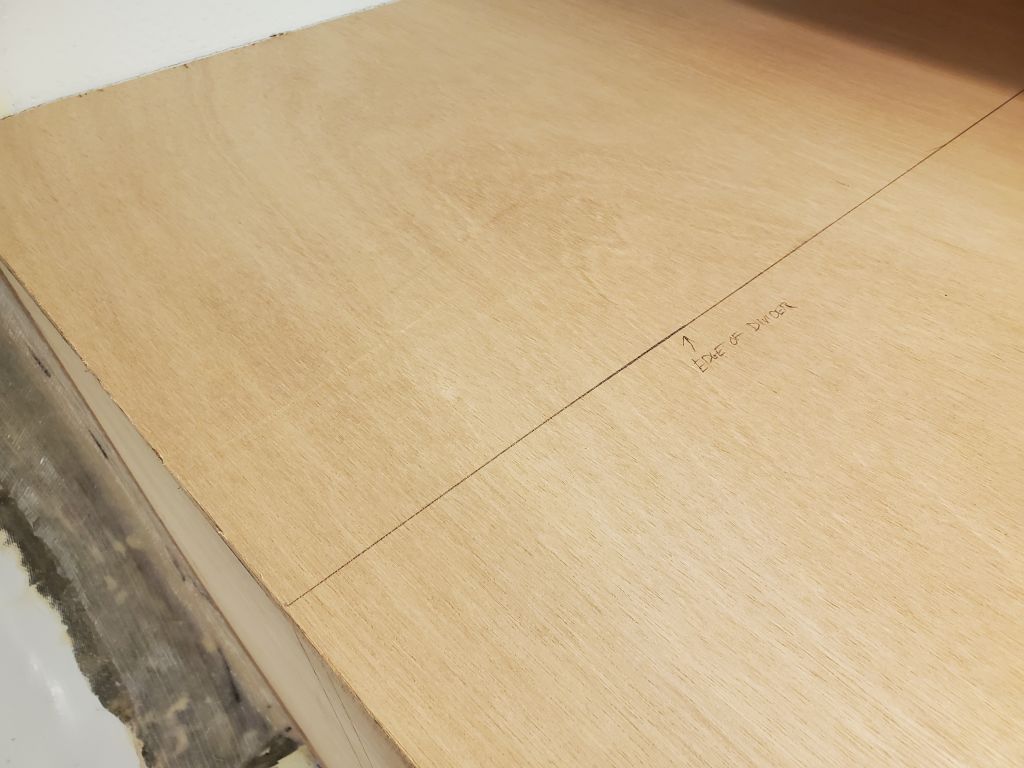
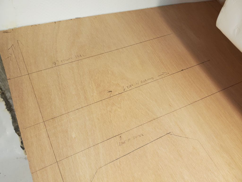
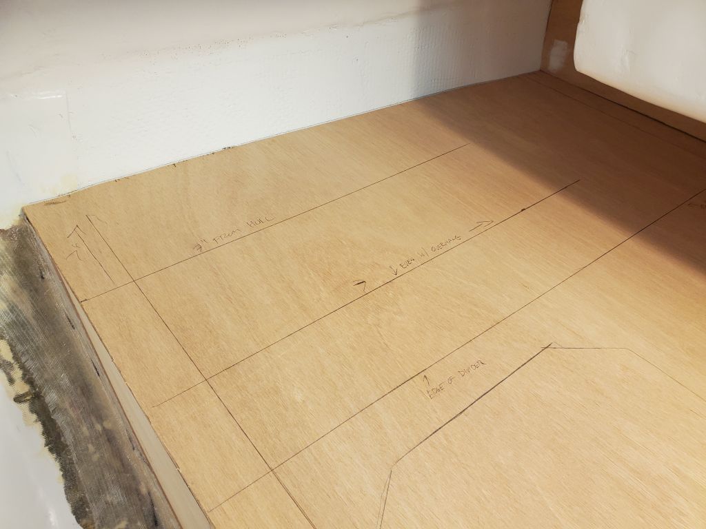
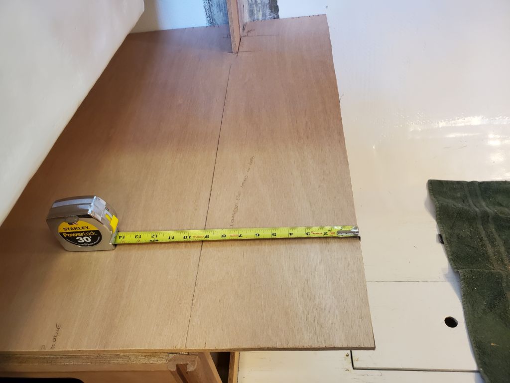
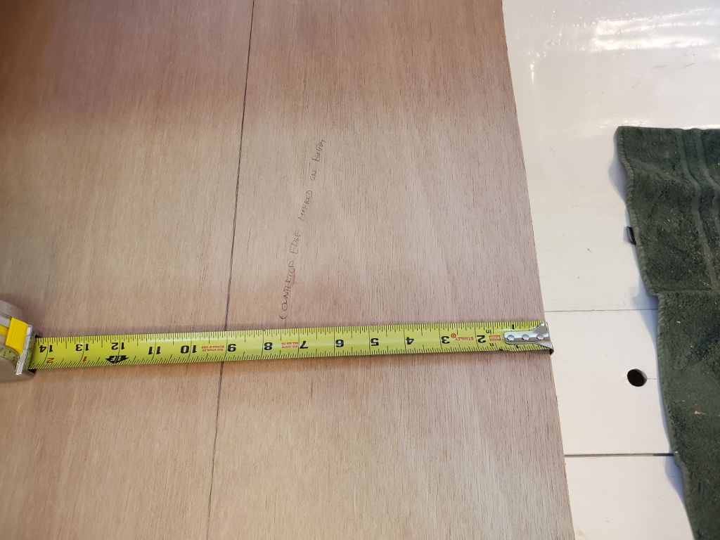
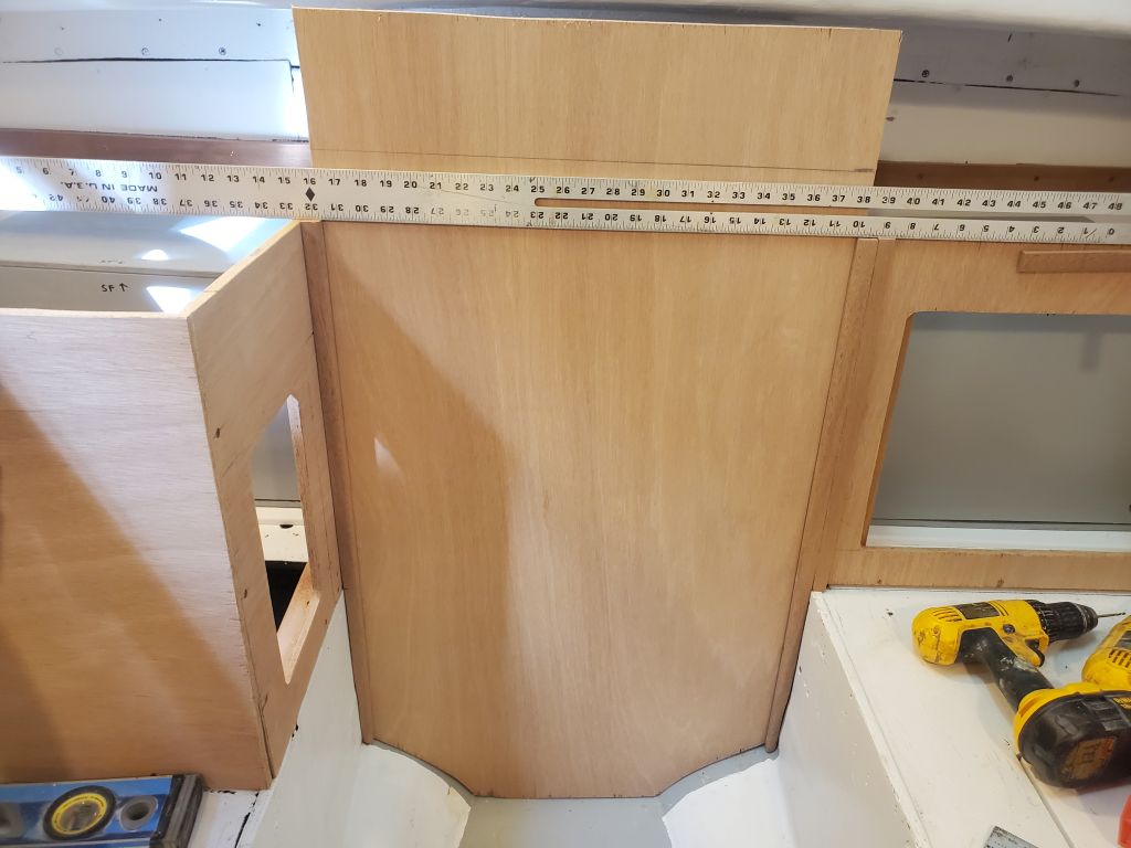
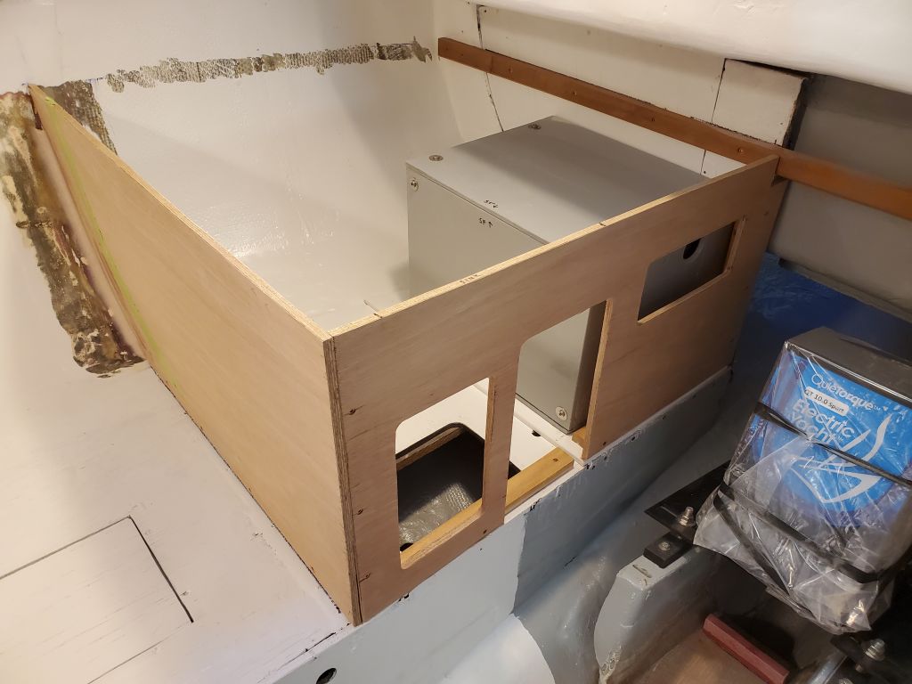
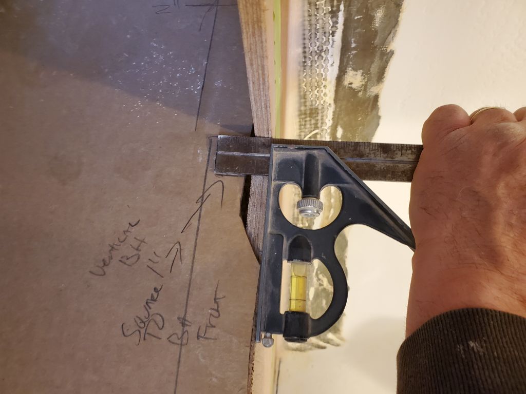
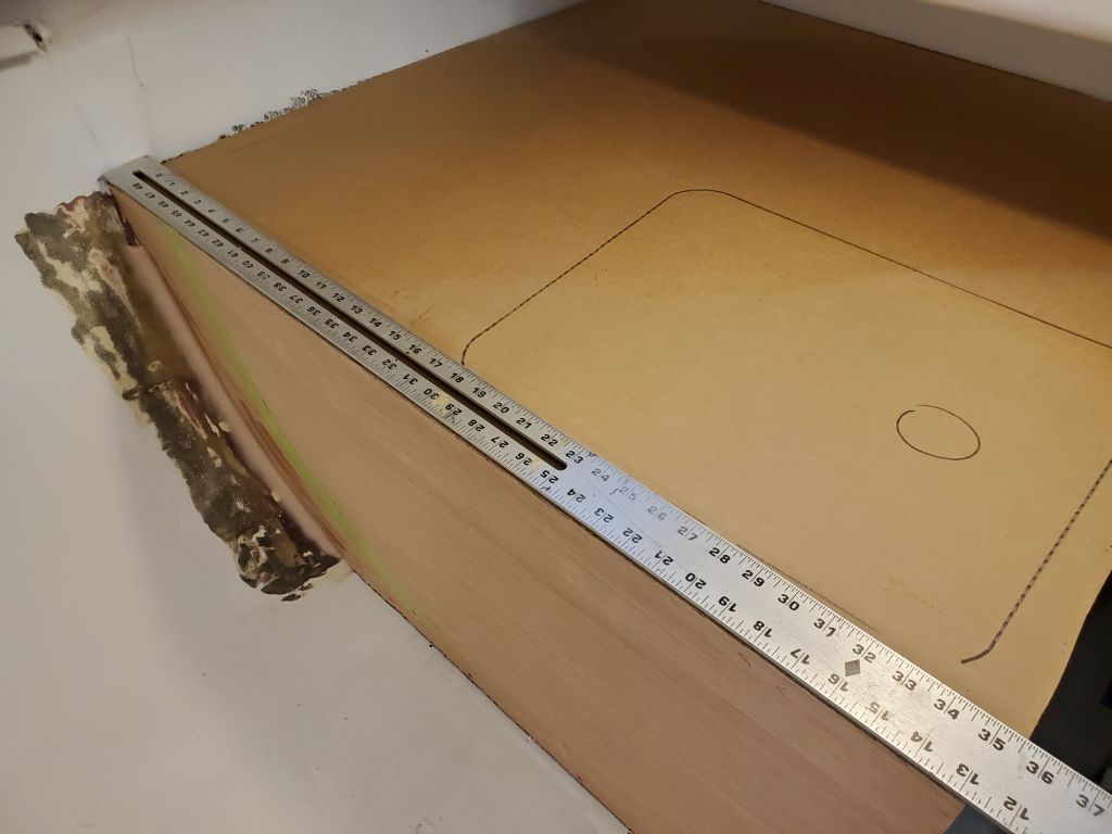
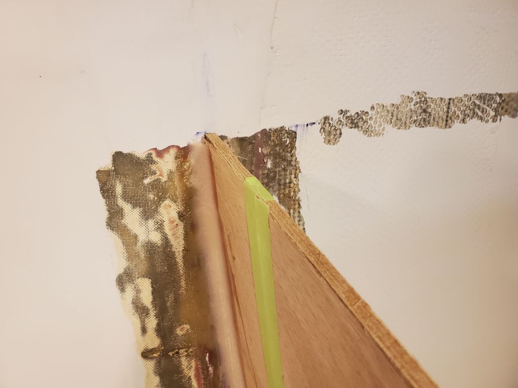
To ensure that the engine room front panel was properly in plane with the port cabinet as intended, once the first stile was in place I used a straightedge to mark the cabinet on the opposite side, at both the top and settee level.  These two marks gave me a layout line where I could align the stile for the starboard side.  For now, I cut the stile to length and shaped the bottom as needed to fit the hull and tabbing and other contours of the cabinetry; this went more quickly than its counterpart to port.

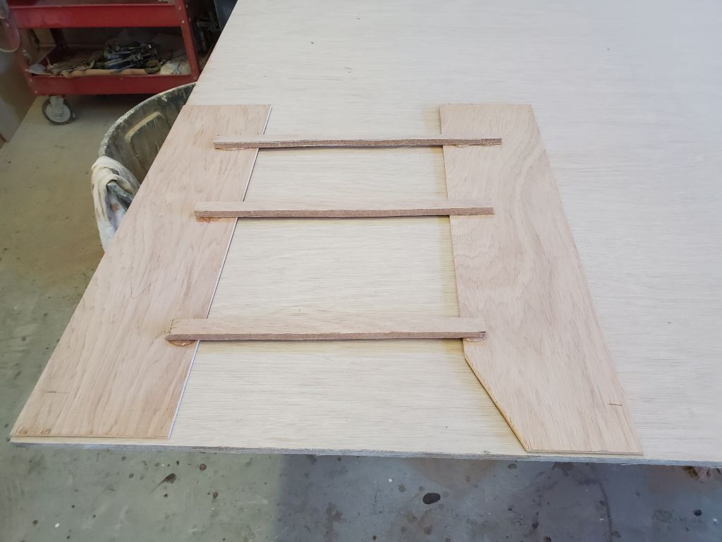
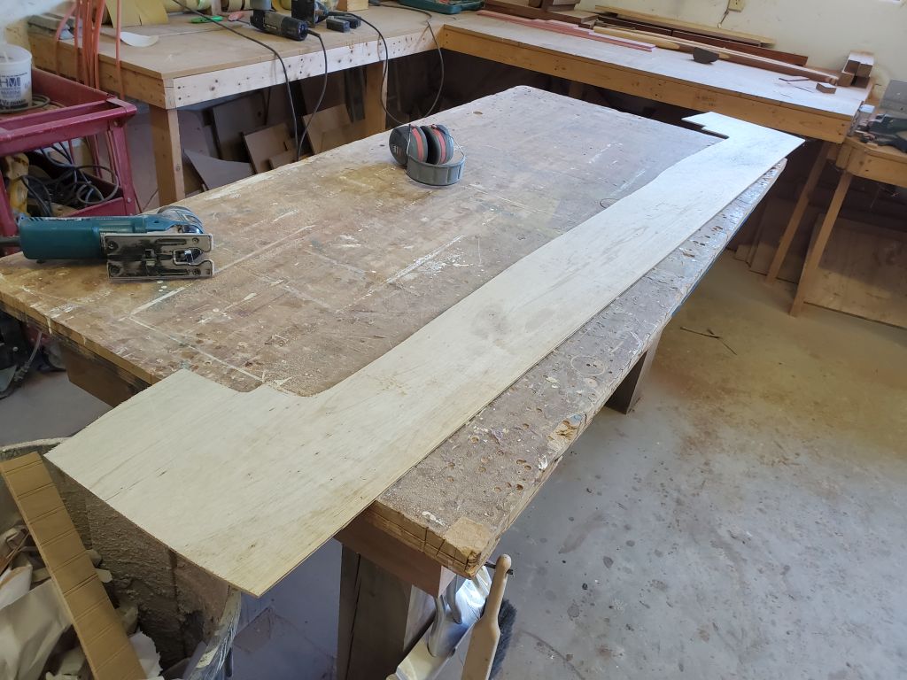
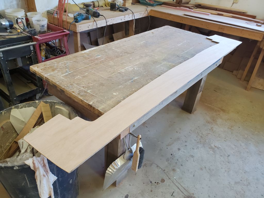
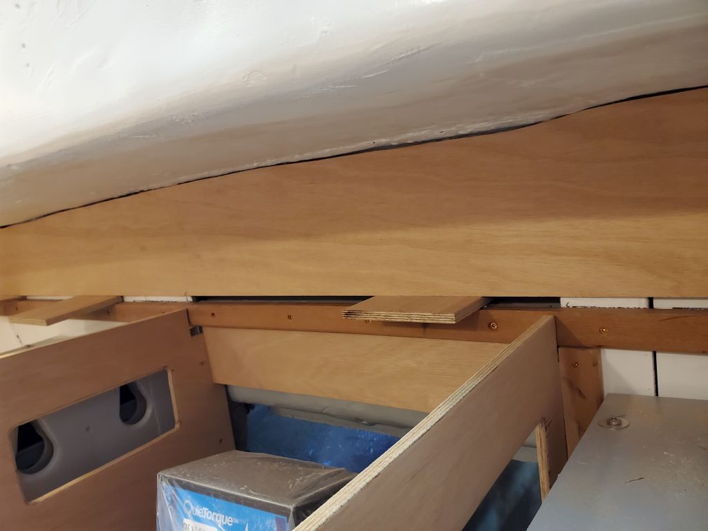
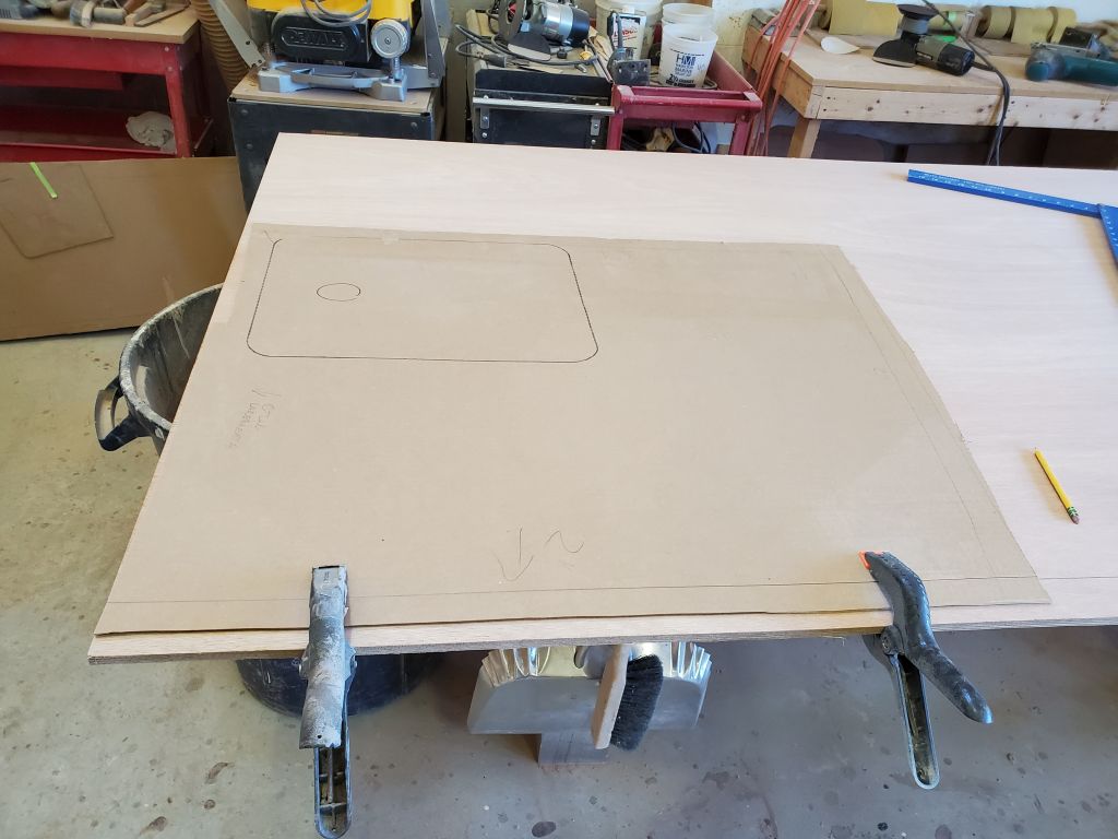
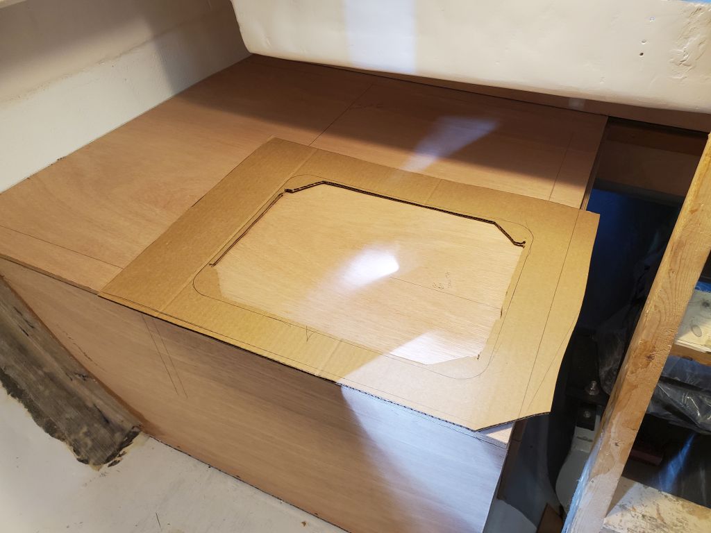
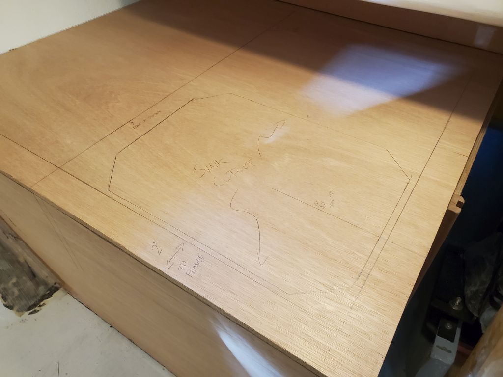
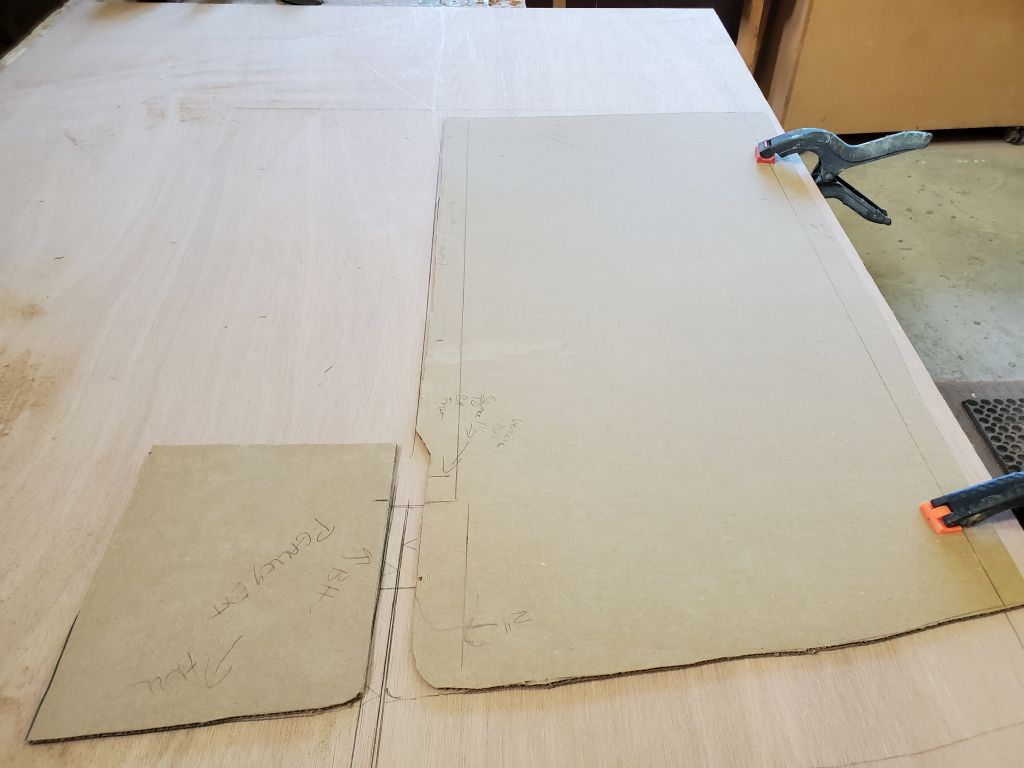
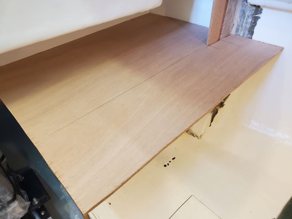
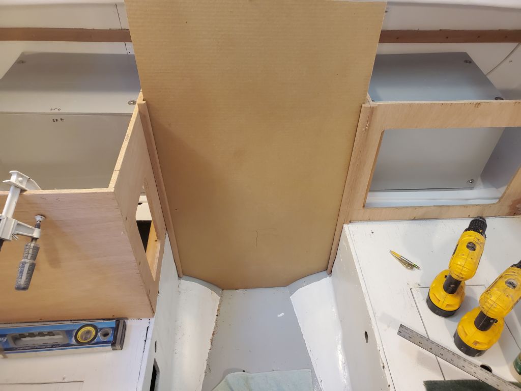
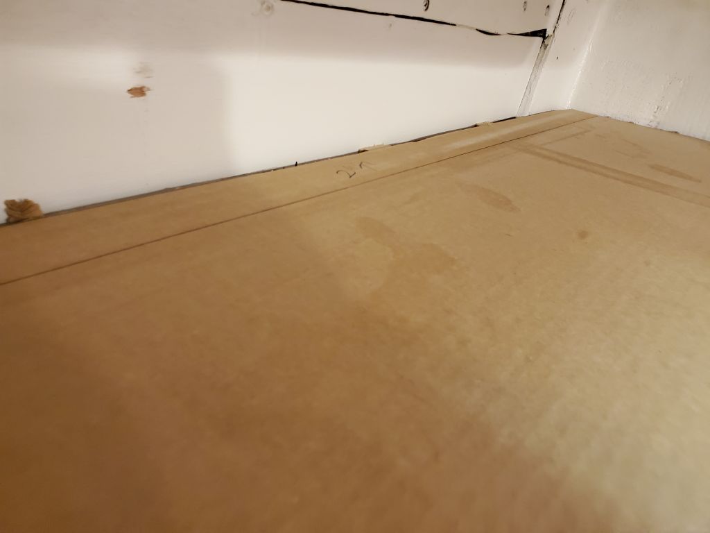
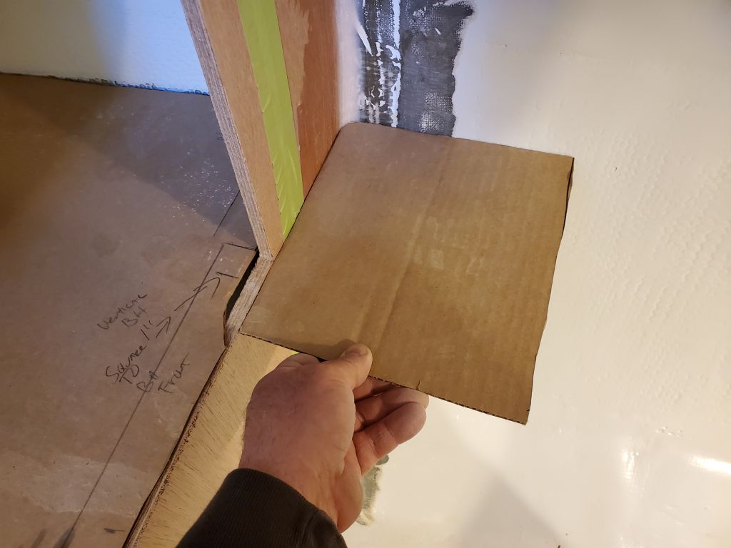
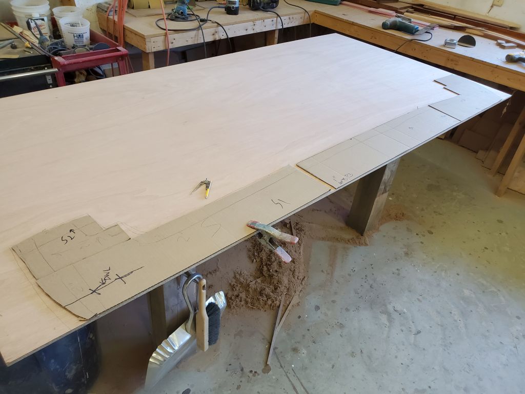
Before installing the stile, however, to be sure it ended up exactly where it needed to be–measurements and transfer marks notwithstanding–I decided to cut and fit the actual plywood panel first, which would help ensure that the stile was where it needed to be.  Starting with my original mockup panel, I decided to cut a new cardboard template since the original was creased and a bit beat up at the sides.  Using the new, fresh cardboard, I made some needed adjustments to the edges of the panel, and eventually transferred it to a section of 12mm plywood for the real thing.  With the base cut roughly to shape according to the template (fine-tuning to come just a little later), once the panel fit well enough in the grooved stile I could finalize the position of the starboard stile and install it with screws.  As it happened, there was a slight, perhaps 3/32″ adjustment to the top edge of the original line I’d struck.

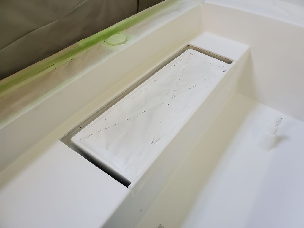
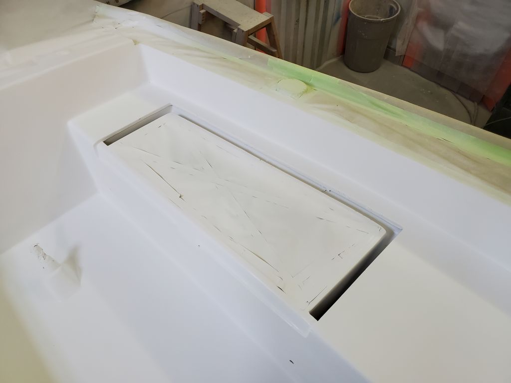
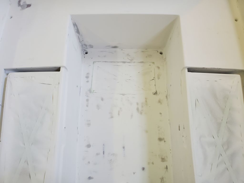
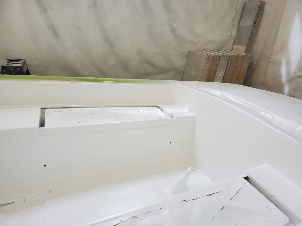
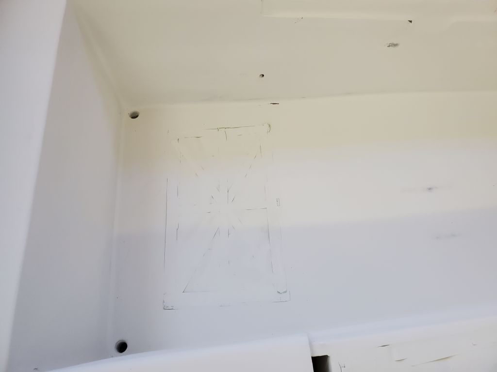
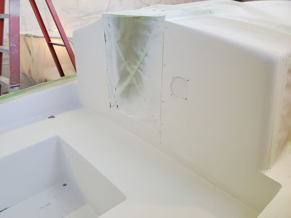
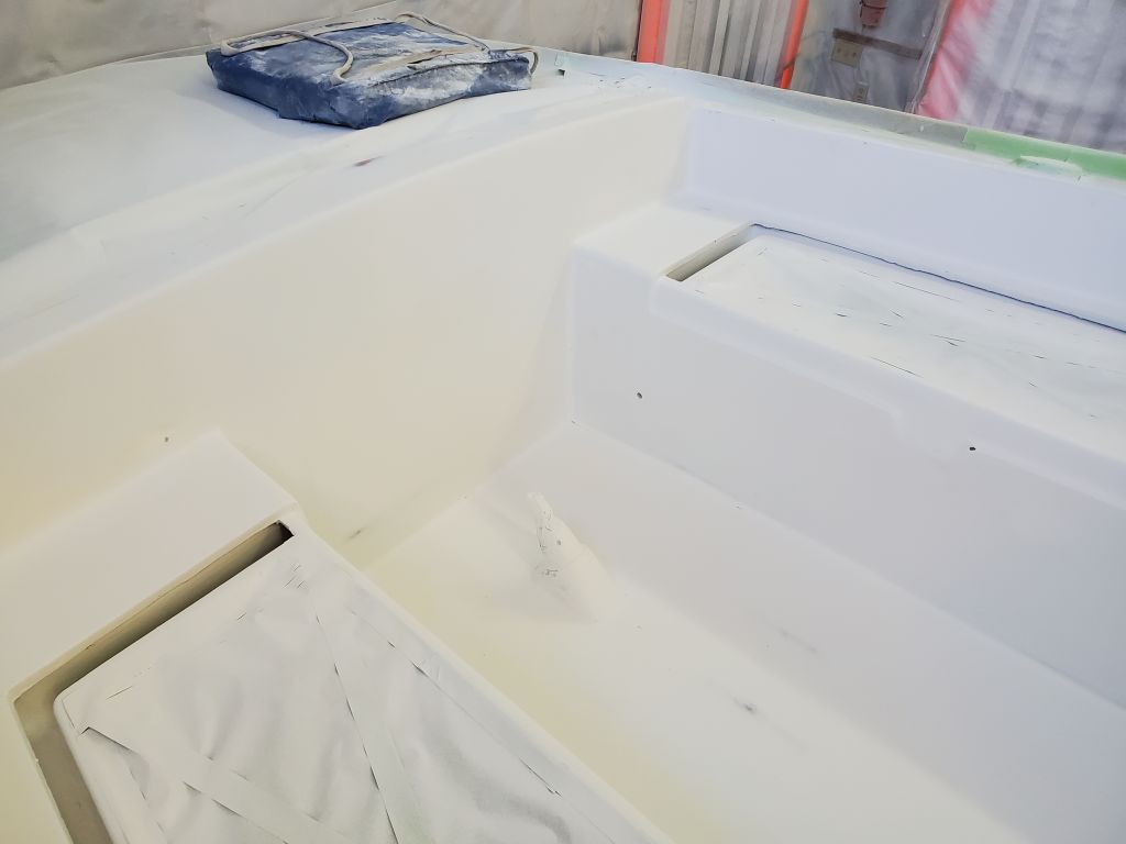
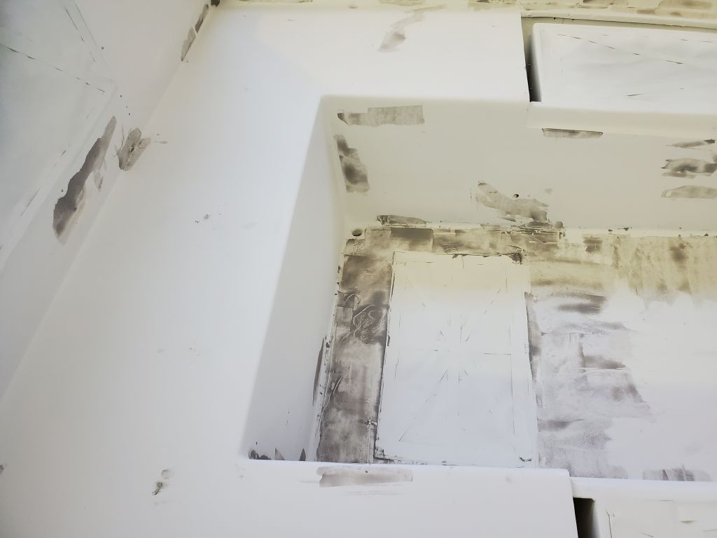
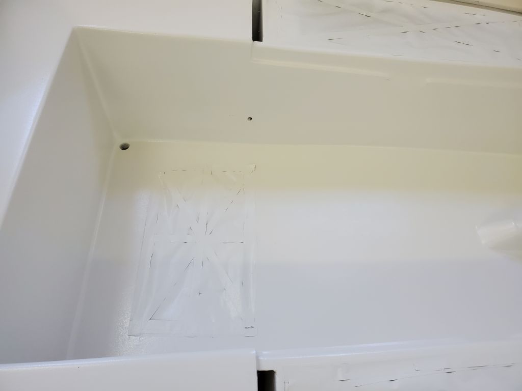
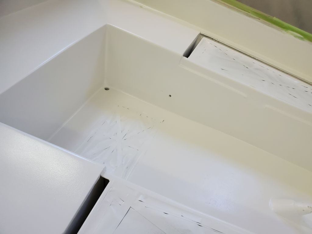
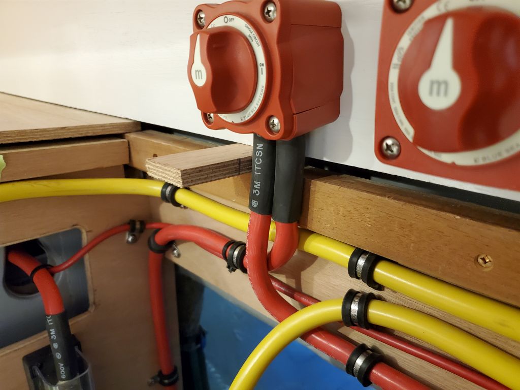
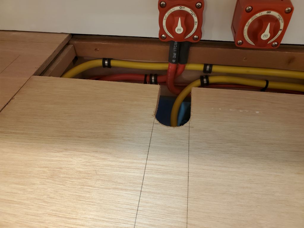
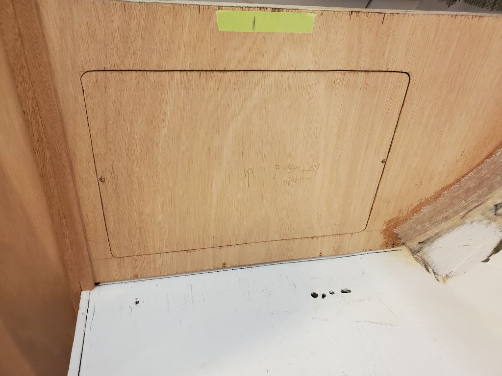
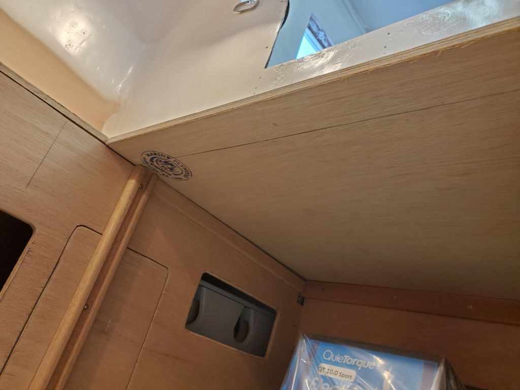
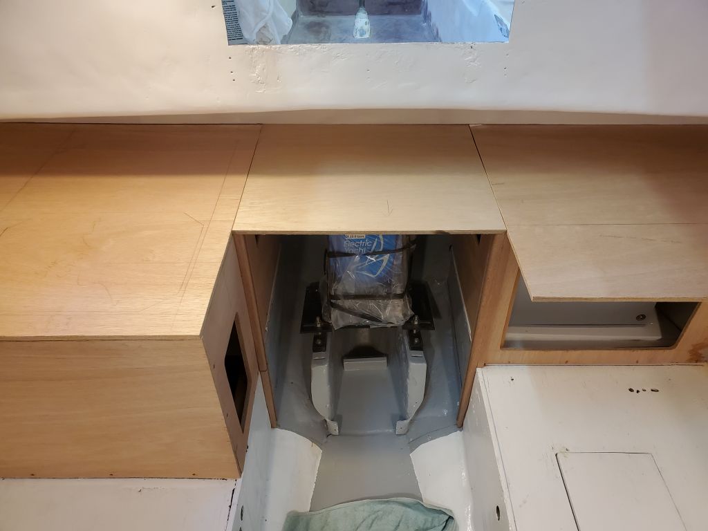
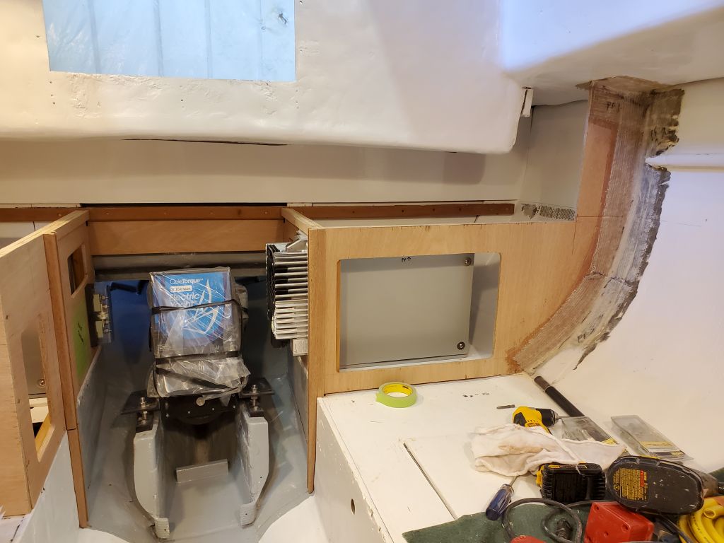
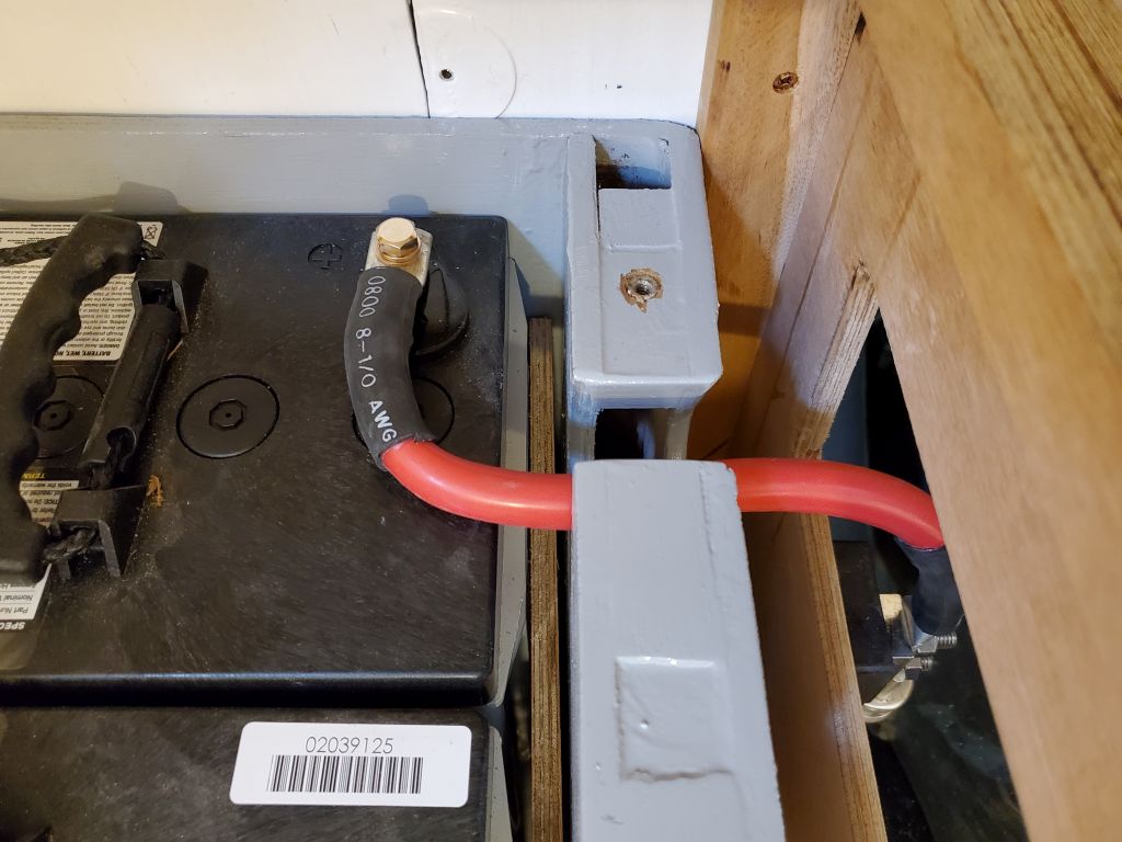
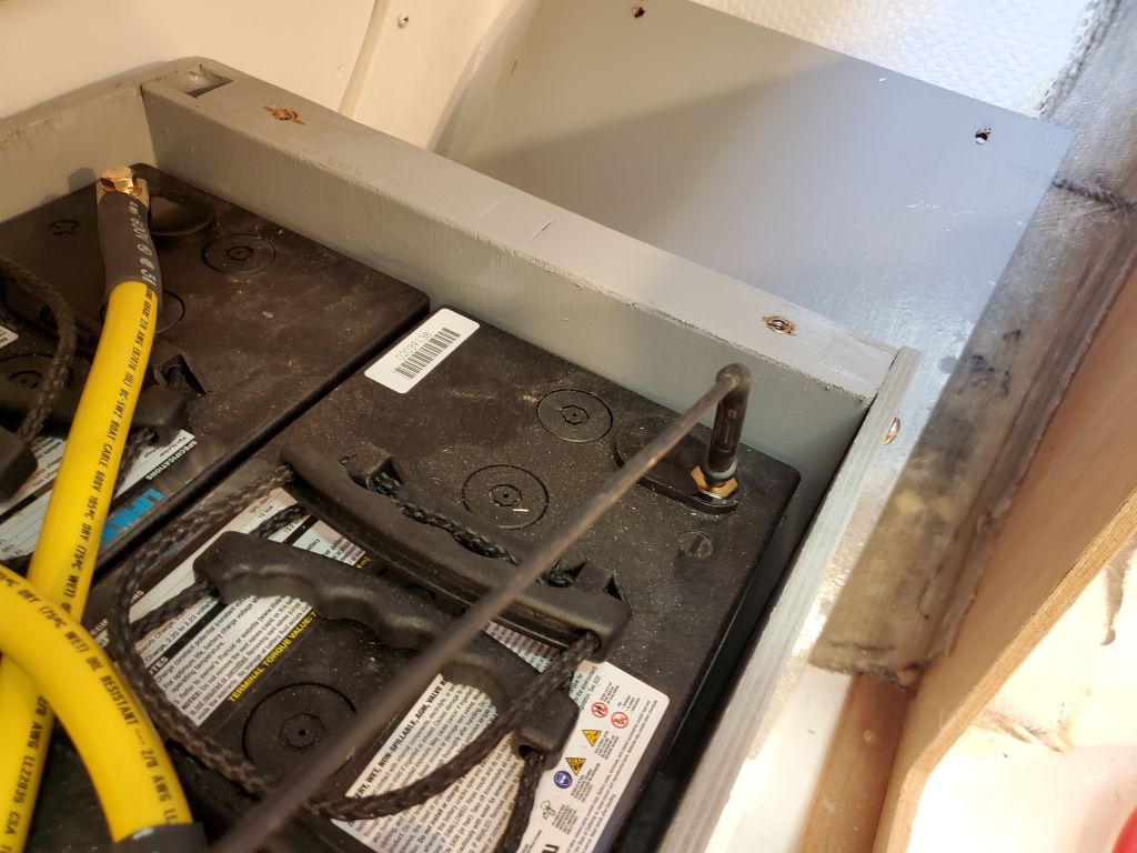
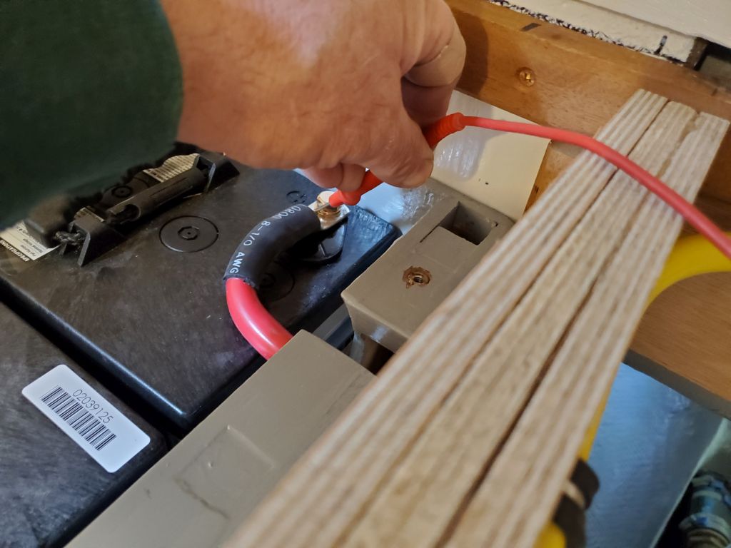
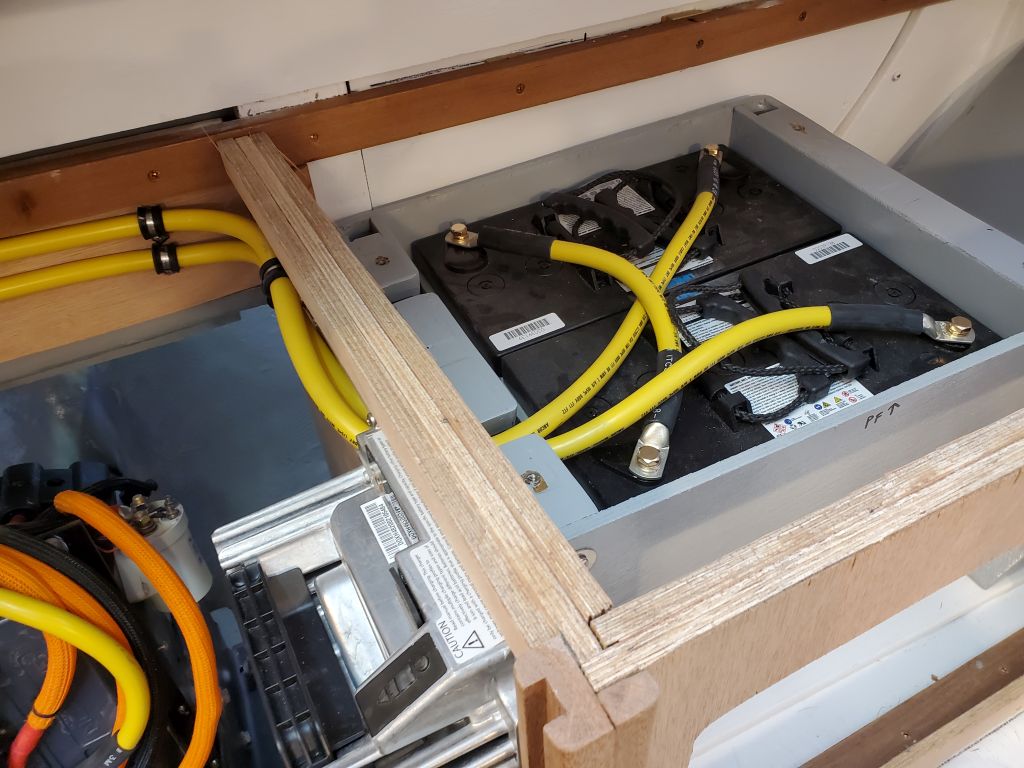
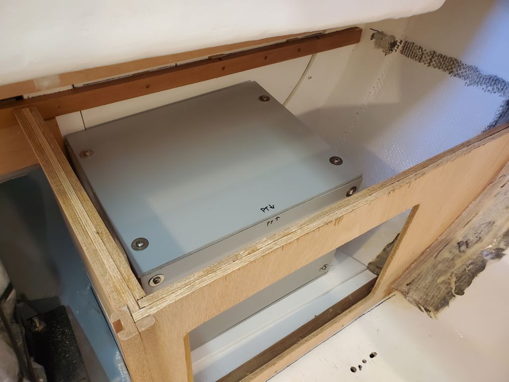
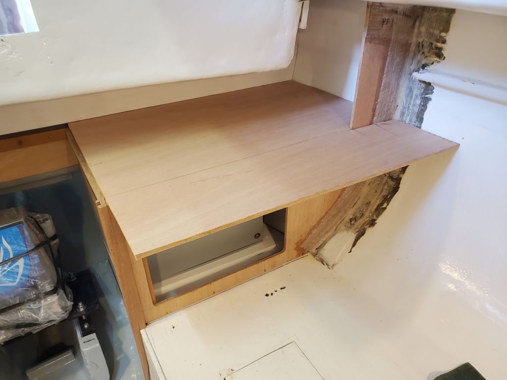
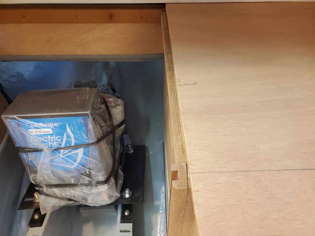
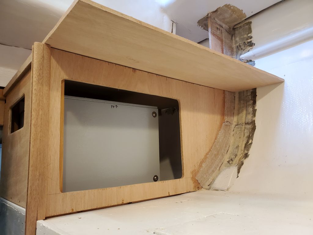
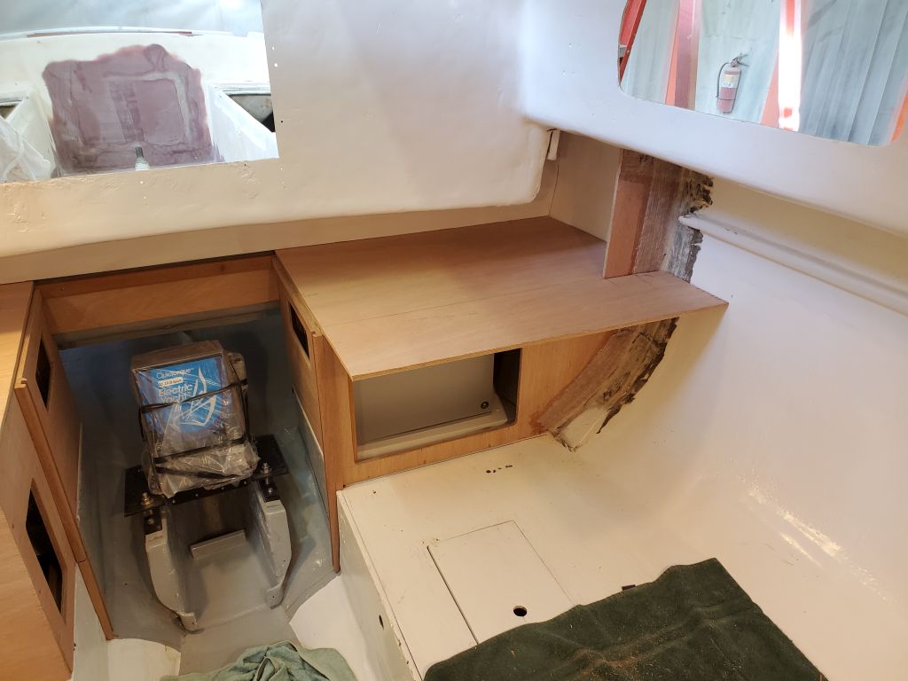
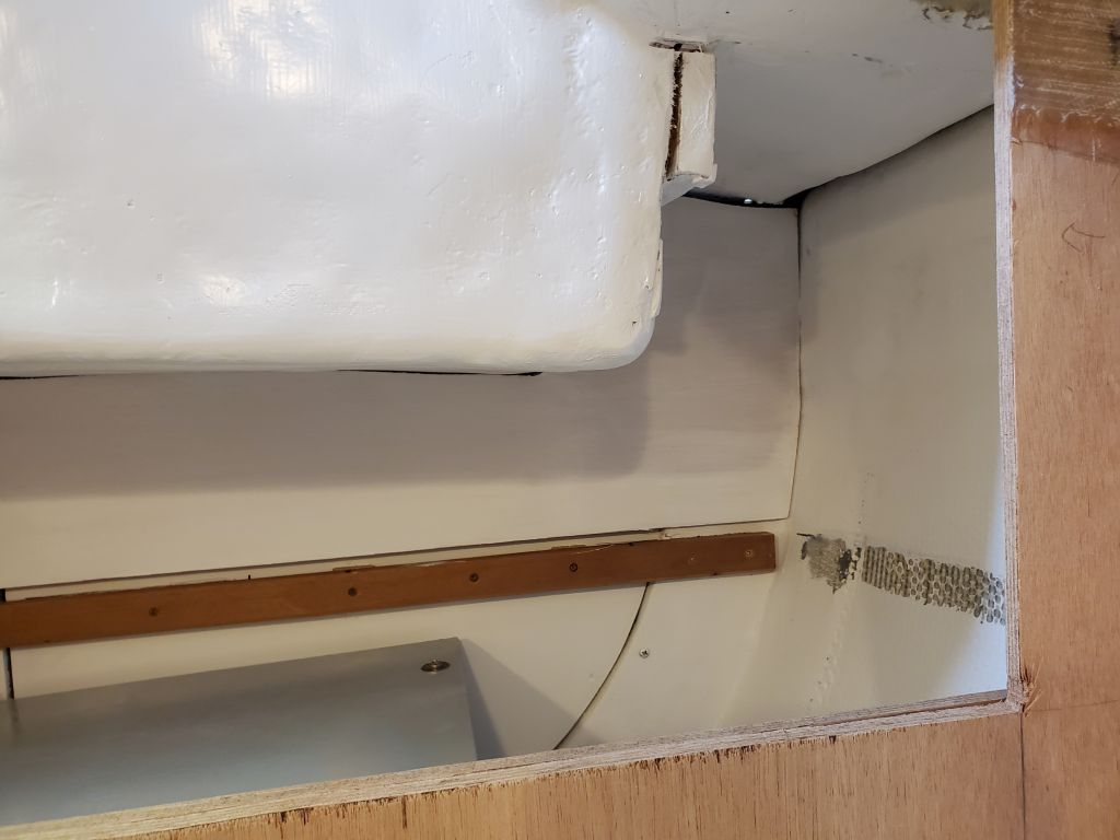
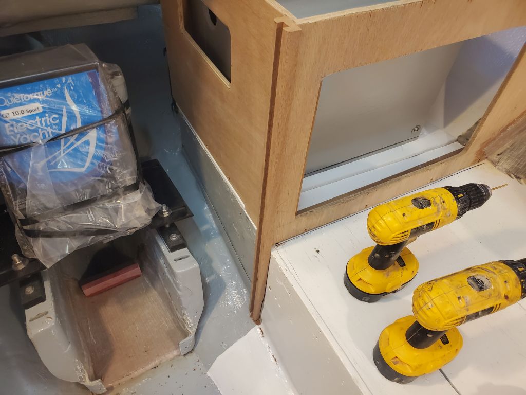
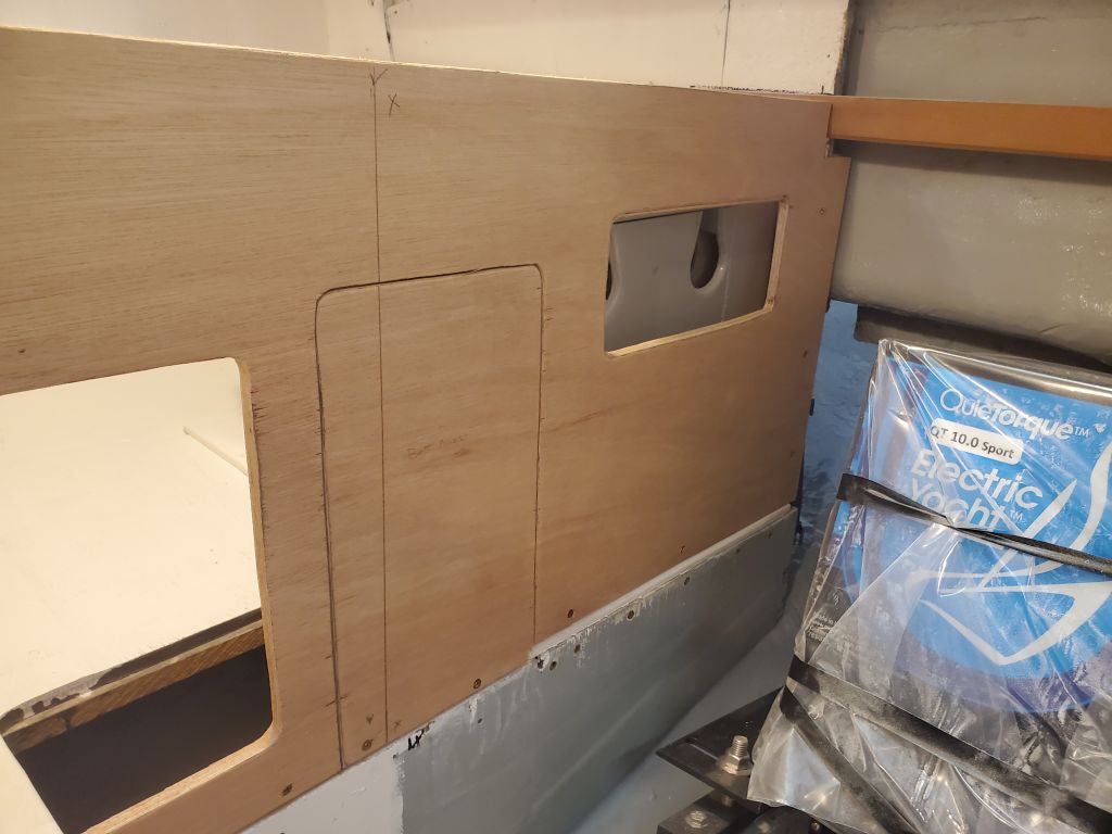
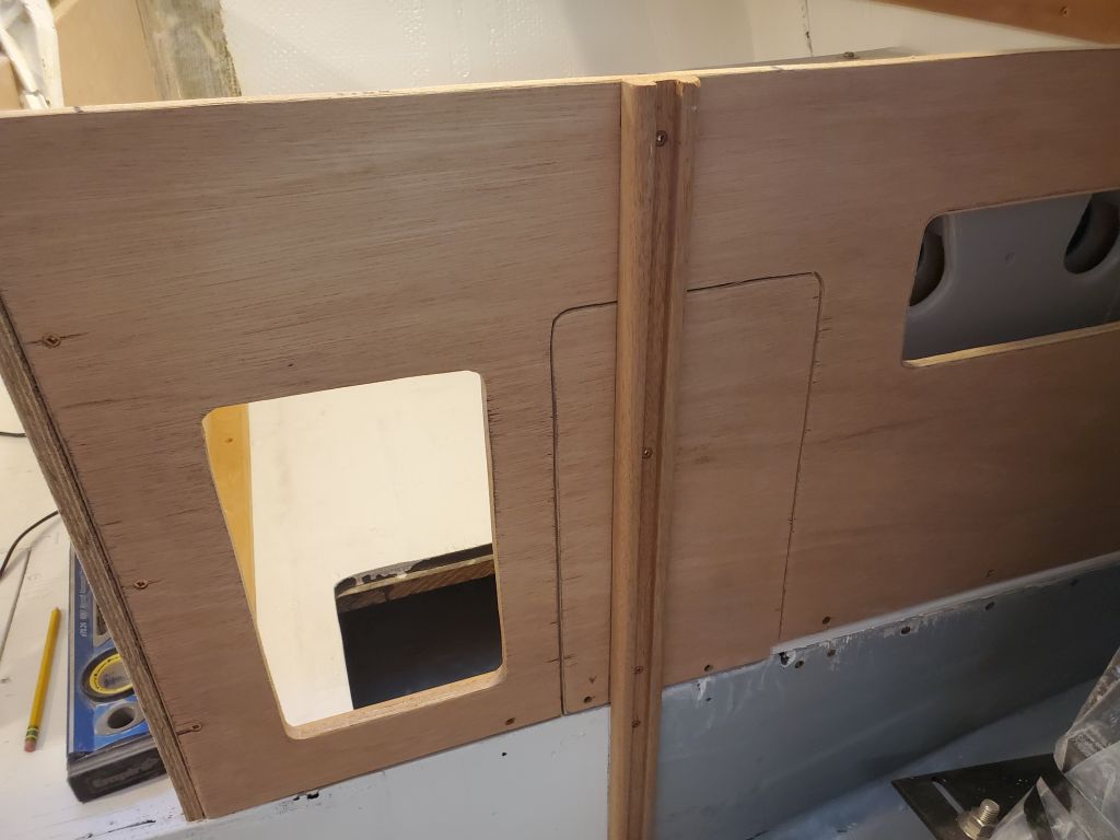
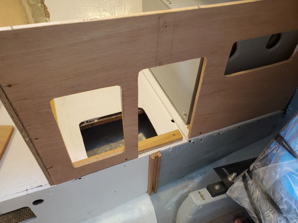
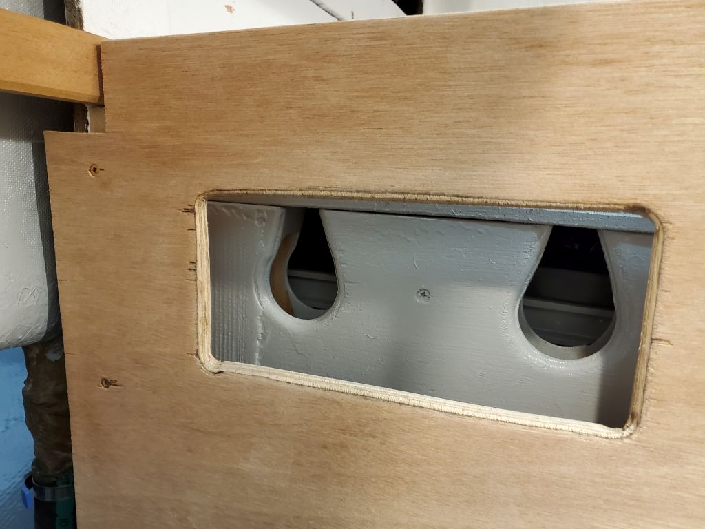
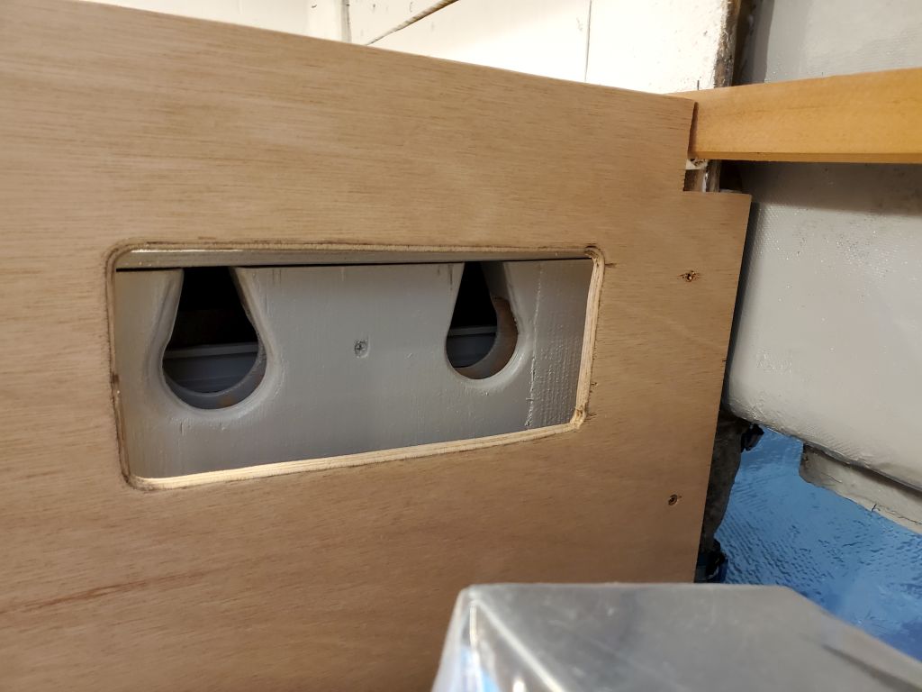
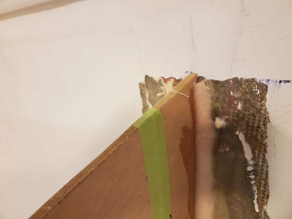
The stile spanned directly the removable battery access panel in the bulkhead, which was expected but turned out to be more useful than anticipated since it would give me a way to secure that panel without additional cleats, enhancing simplicity and avoiding undue obstructions in the right-sized opening.

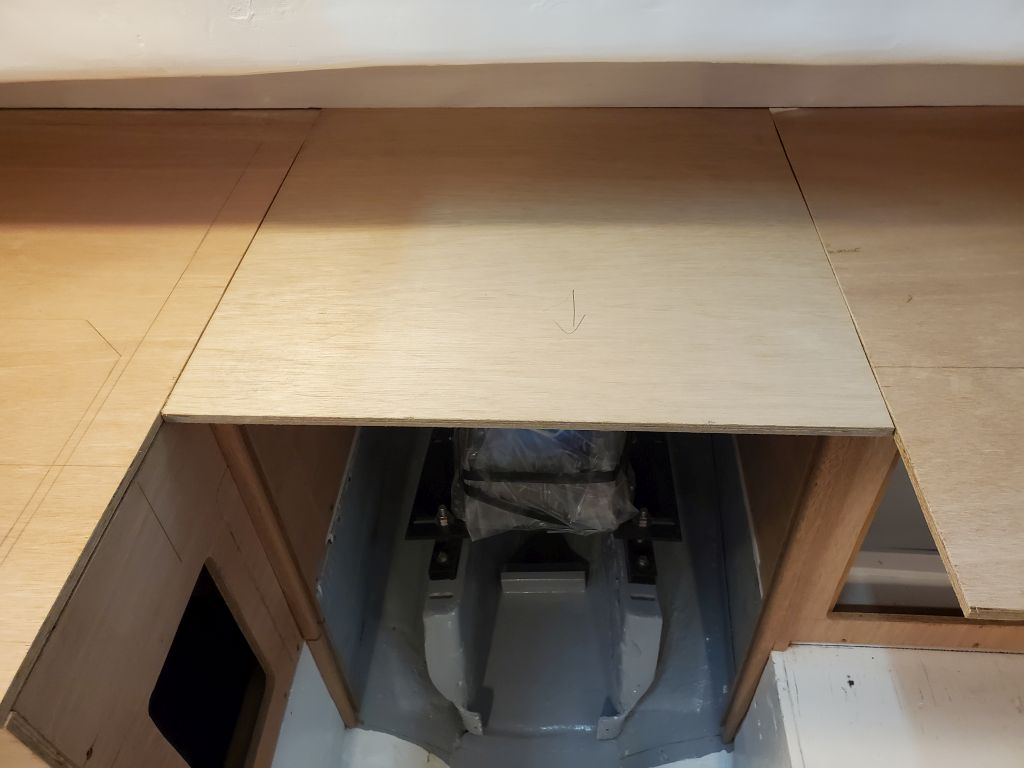
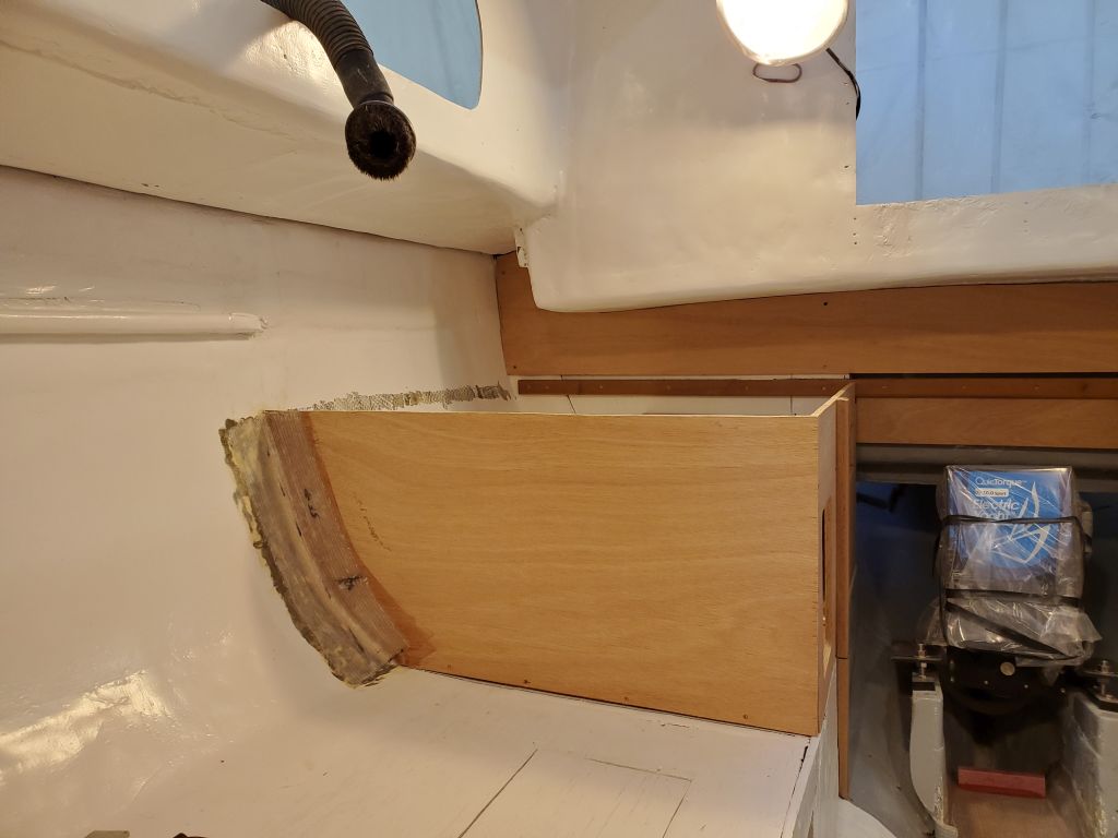
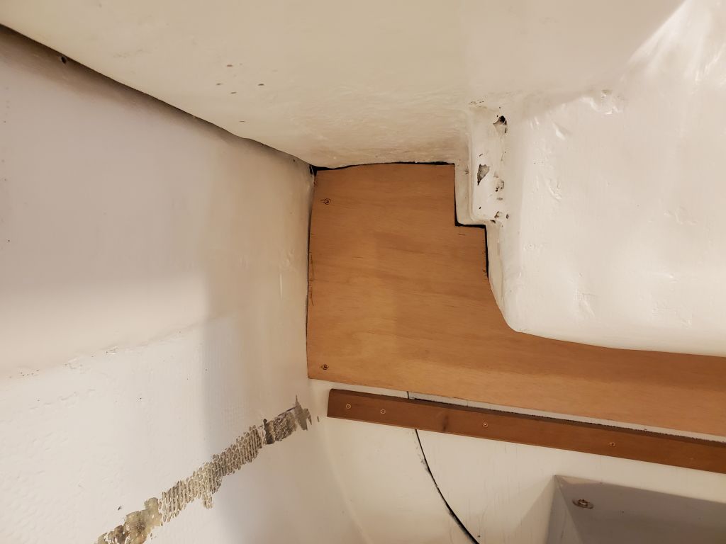
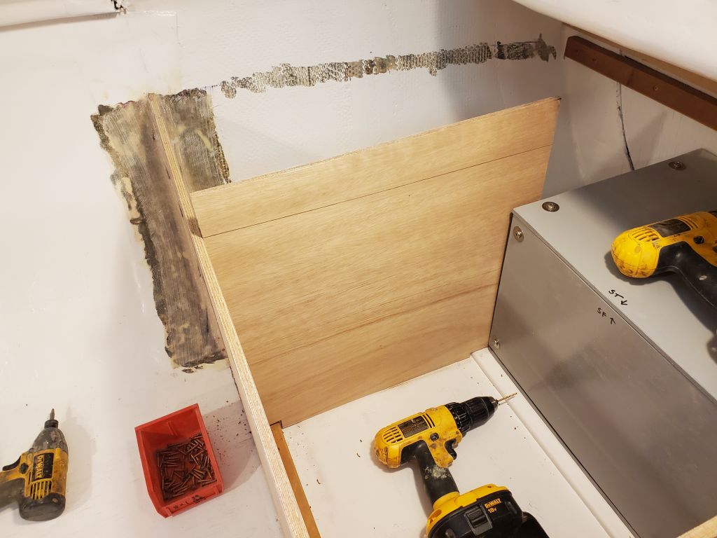
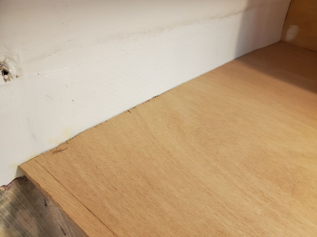
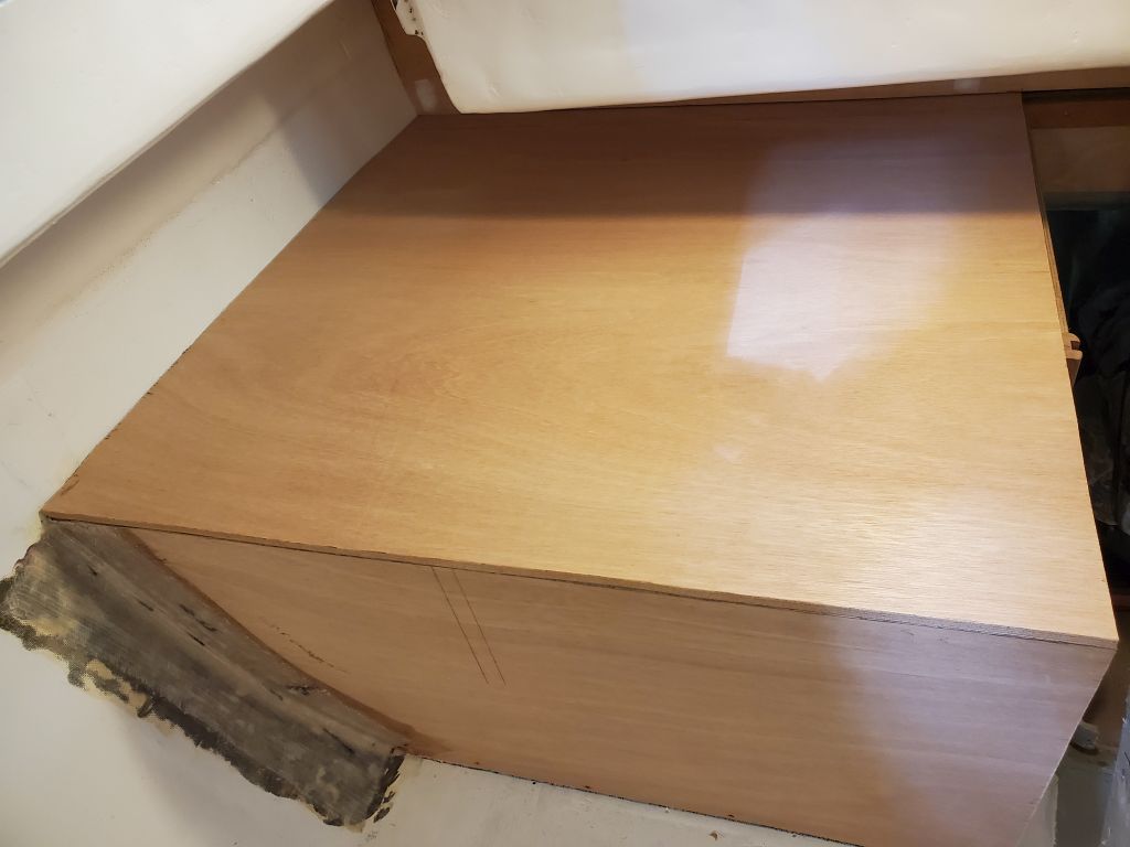
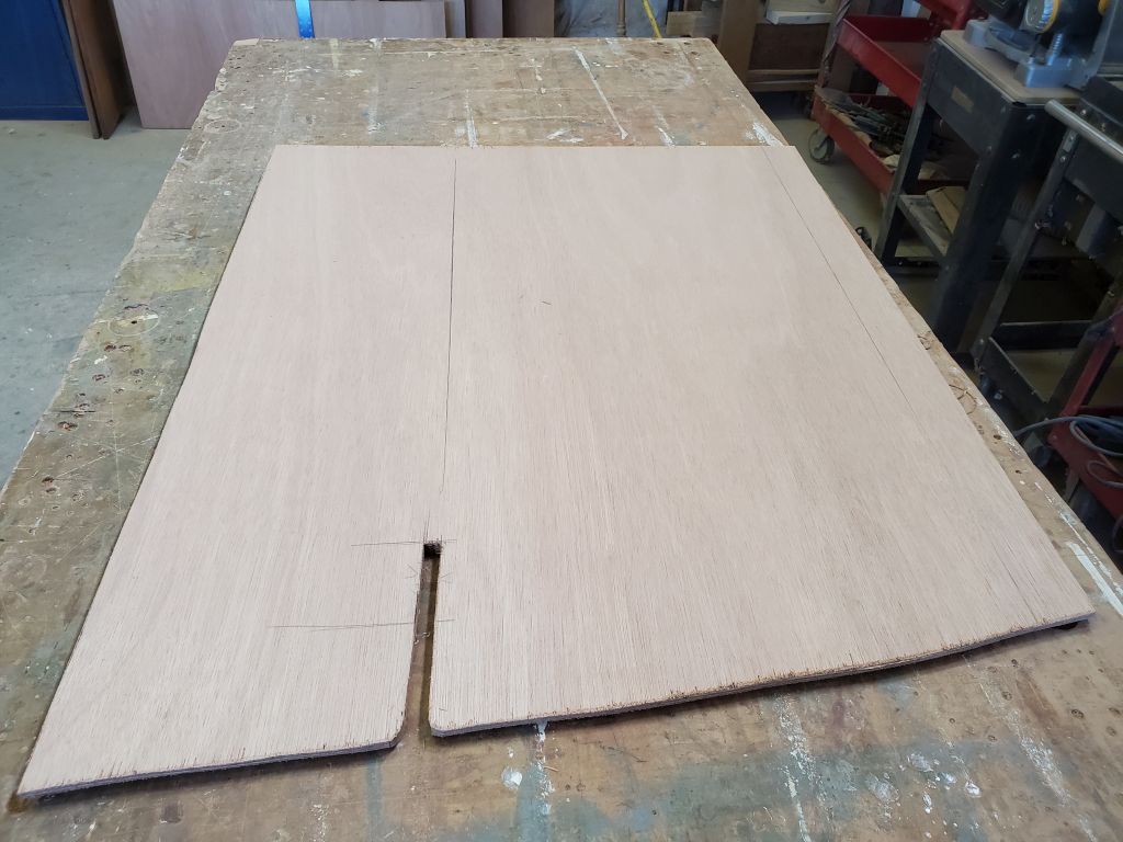
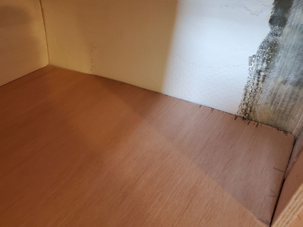
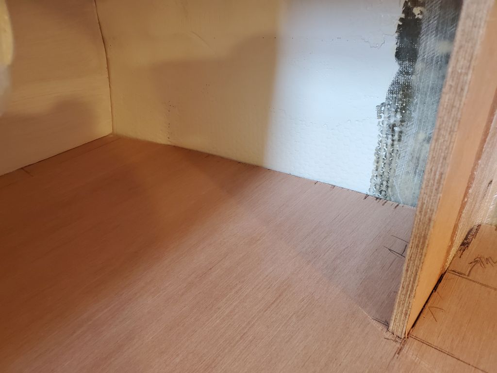
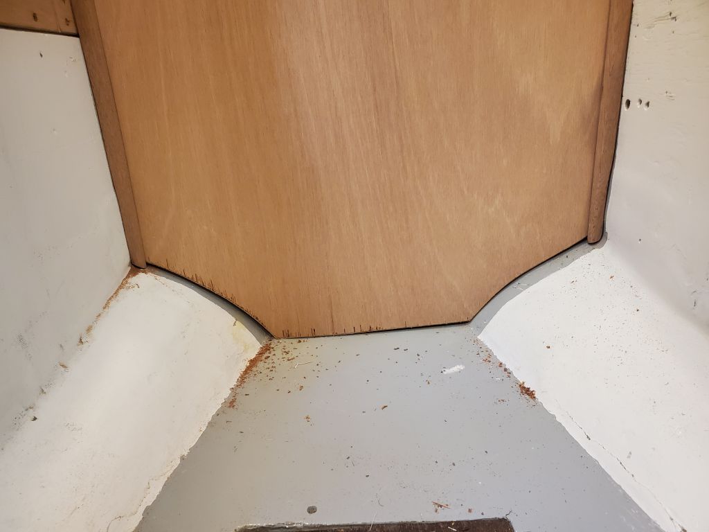
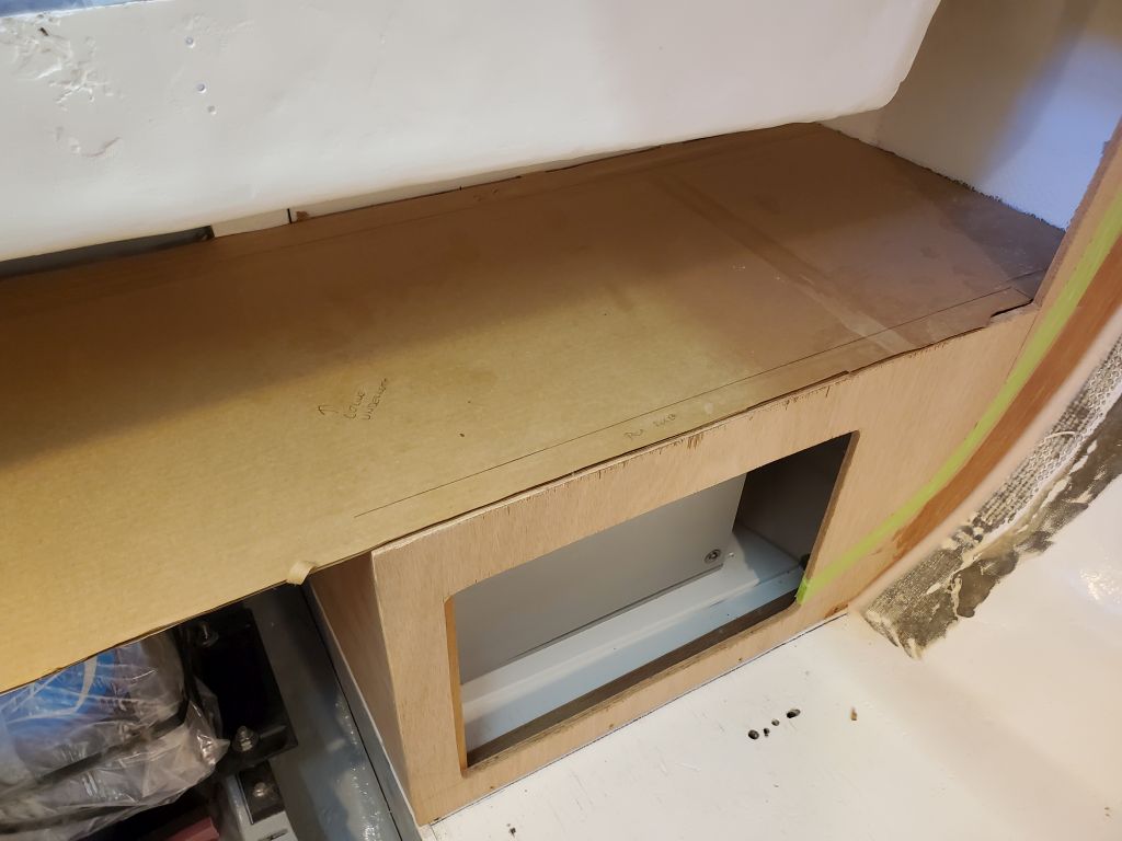
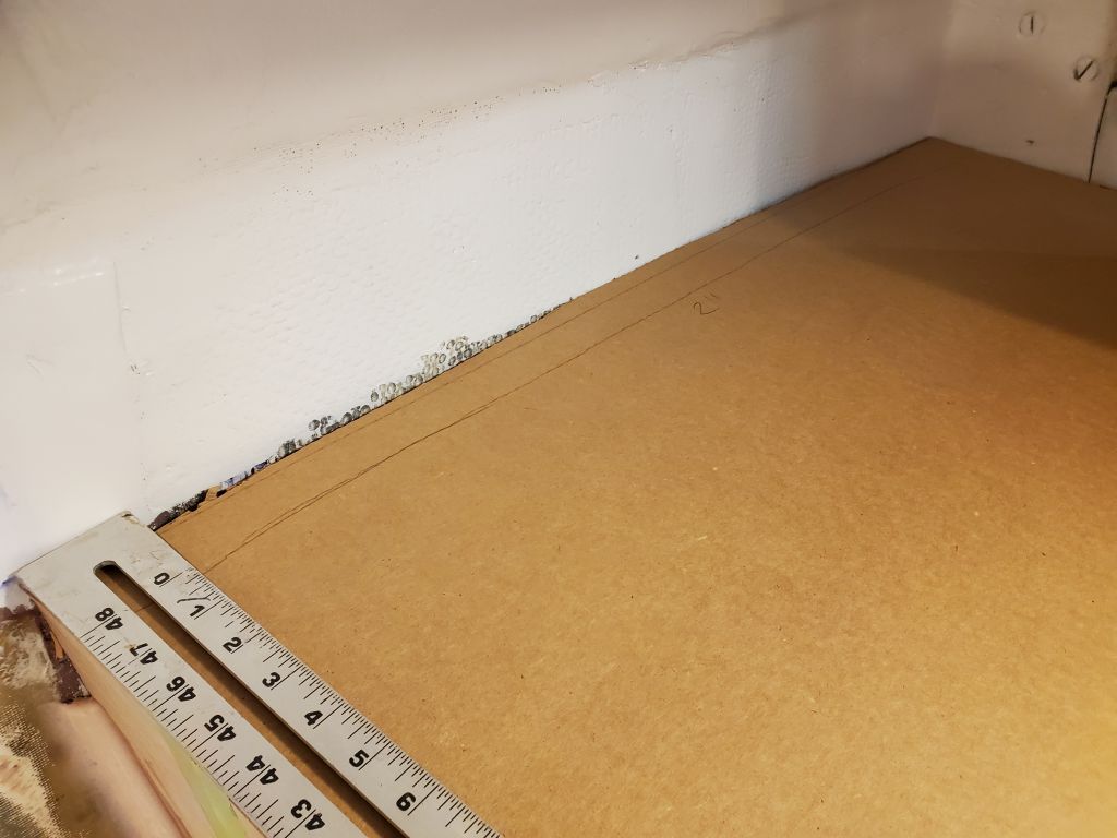
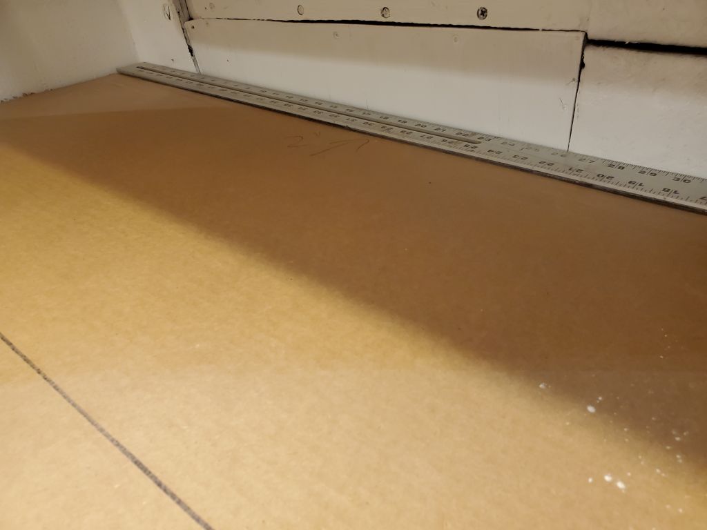
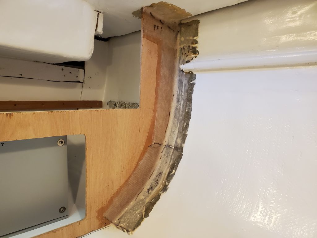
Now I scribed, cut, and fitted the bottom edge of the panel to better fit the curvature of the hull and cabin sole.  Once I was satisfied with the fit, I used a straightedge across the two sides of the galley to strike the top edge of the panel and cut it to the correct and final height.

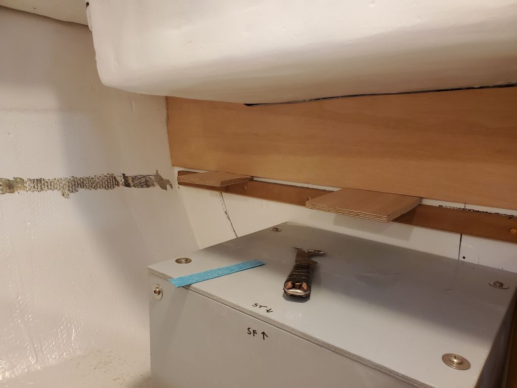
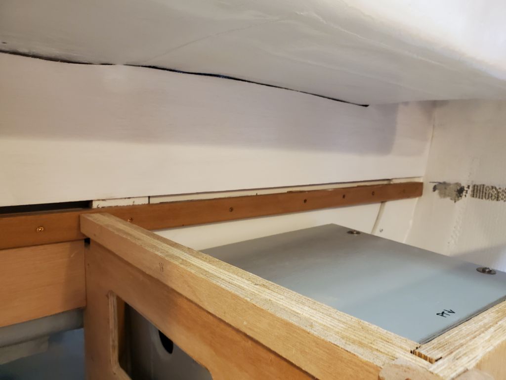
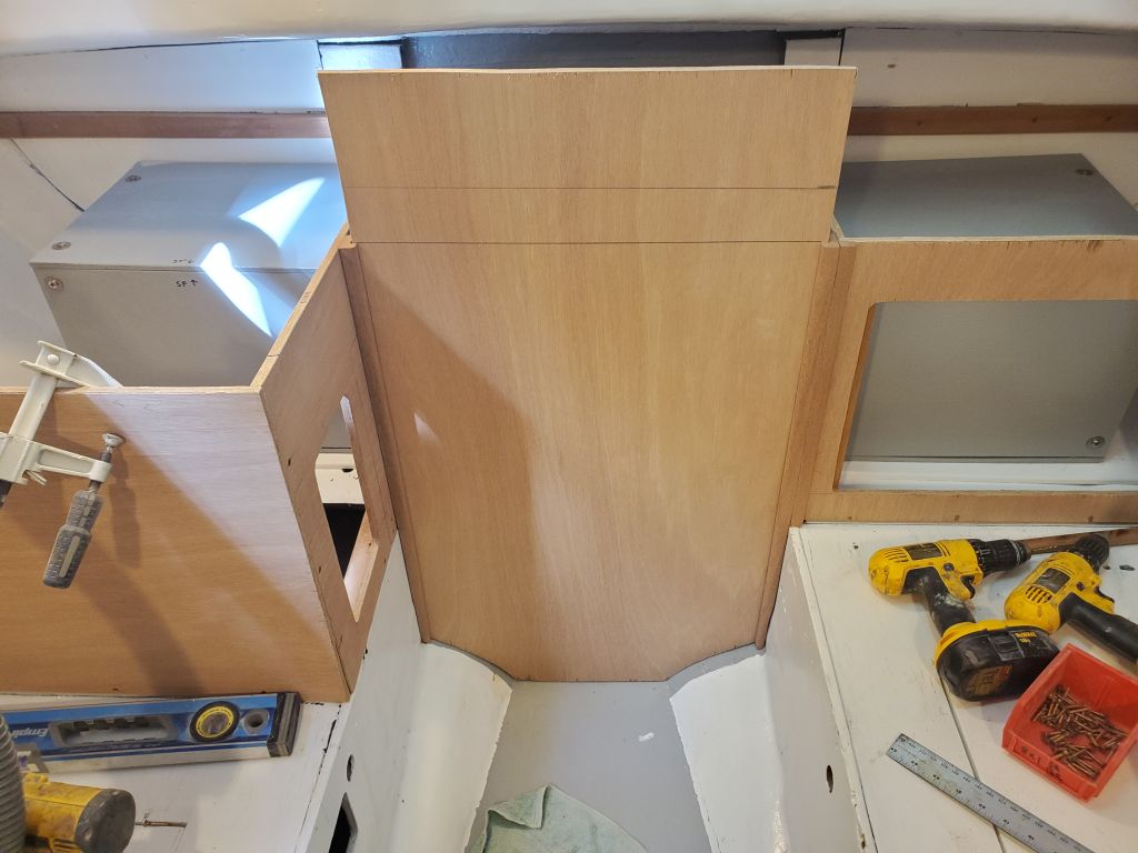
To allow the battery panel to be removable if needed, I marked and cut the engine panel stile just below the bottom of the battery panel, creating two sections.  The top section, secured to the panel with two screws and glue, held the panel securely, while the top few inches of the stile, which secured to the main bulkhead with a single screw, held the panel properly in place and alignment with the surrounding cabinetry.  With one additional screw through the bottom of the small panel into the cleat on the settee, this panel was well-secured, yet easily removable when needed.

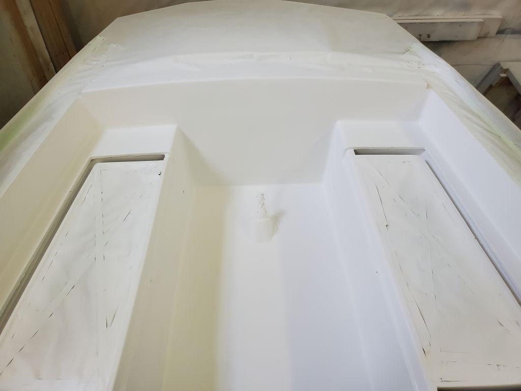
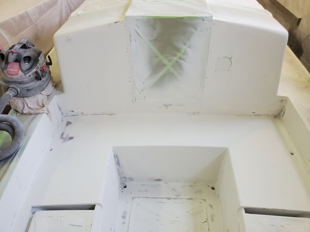
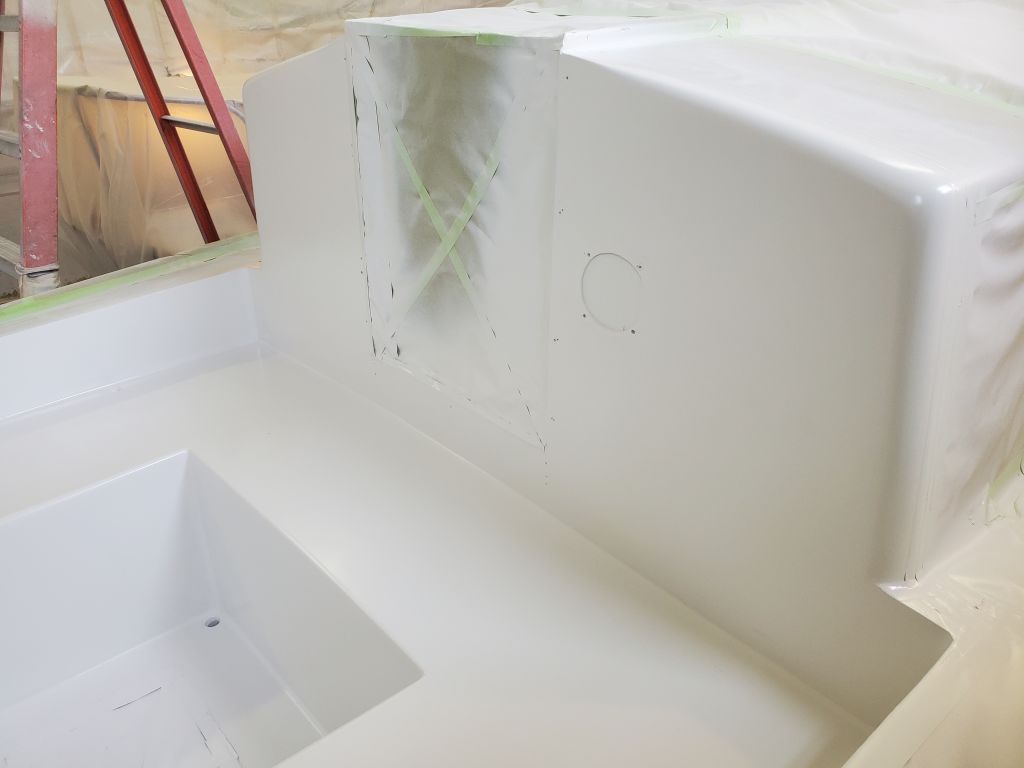
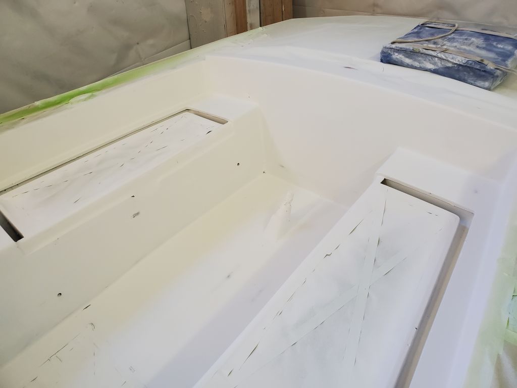
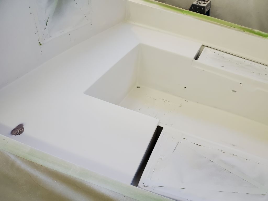
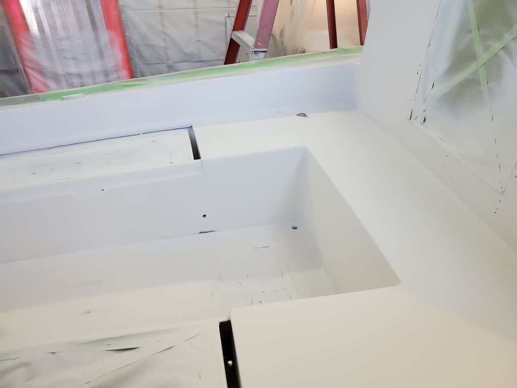
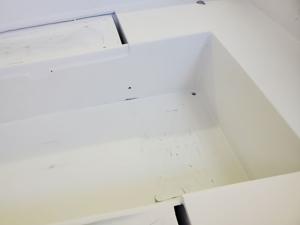
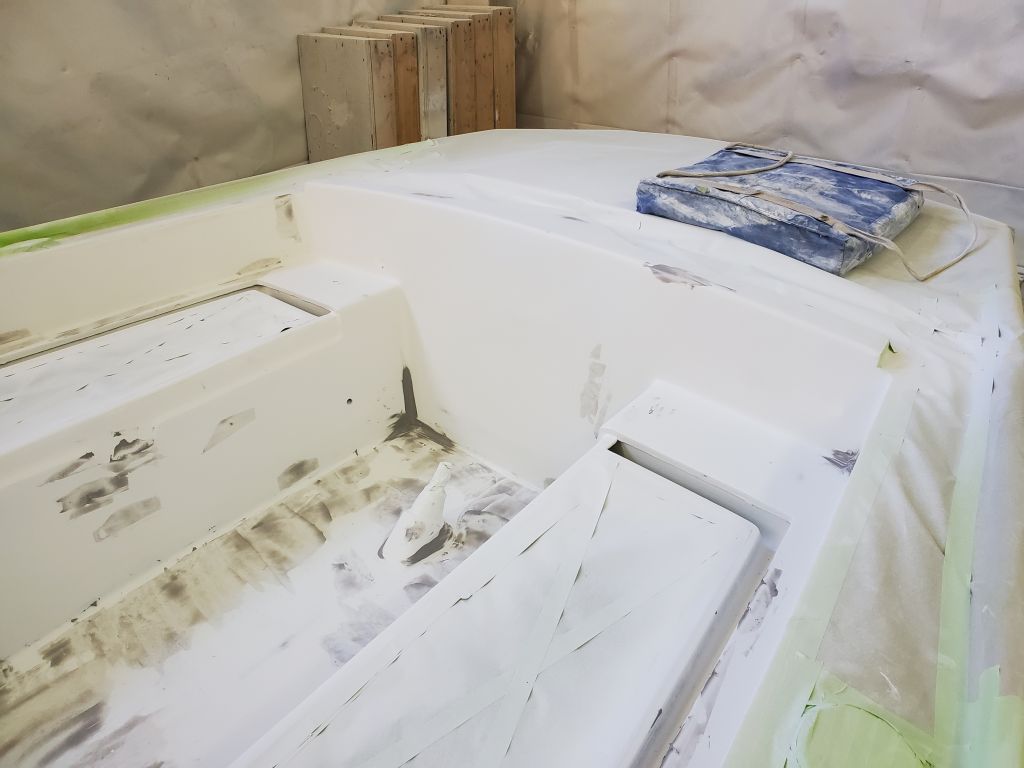
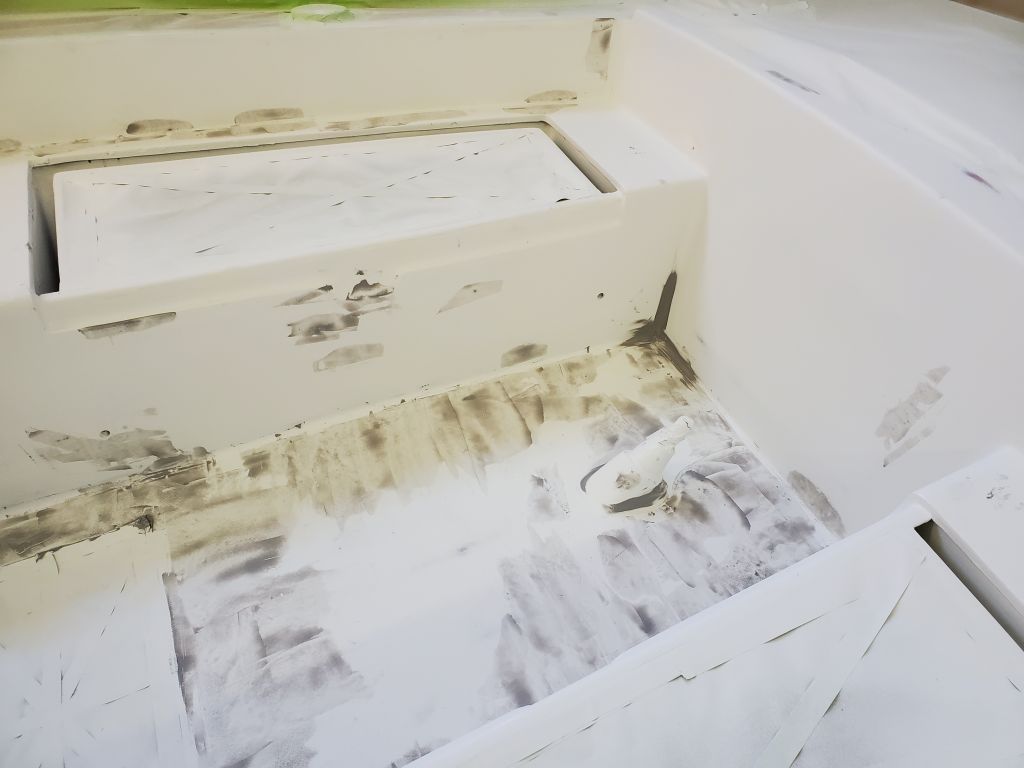
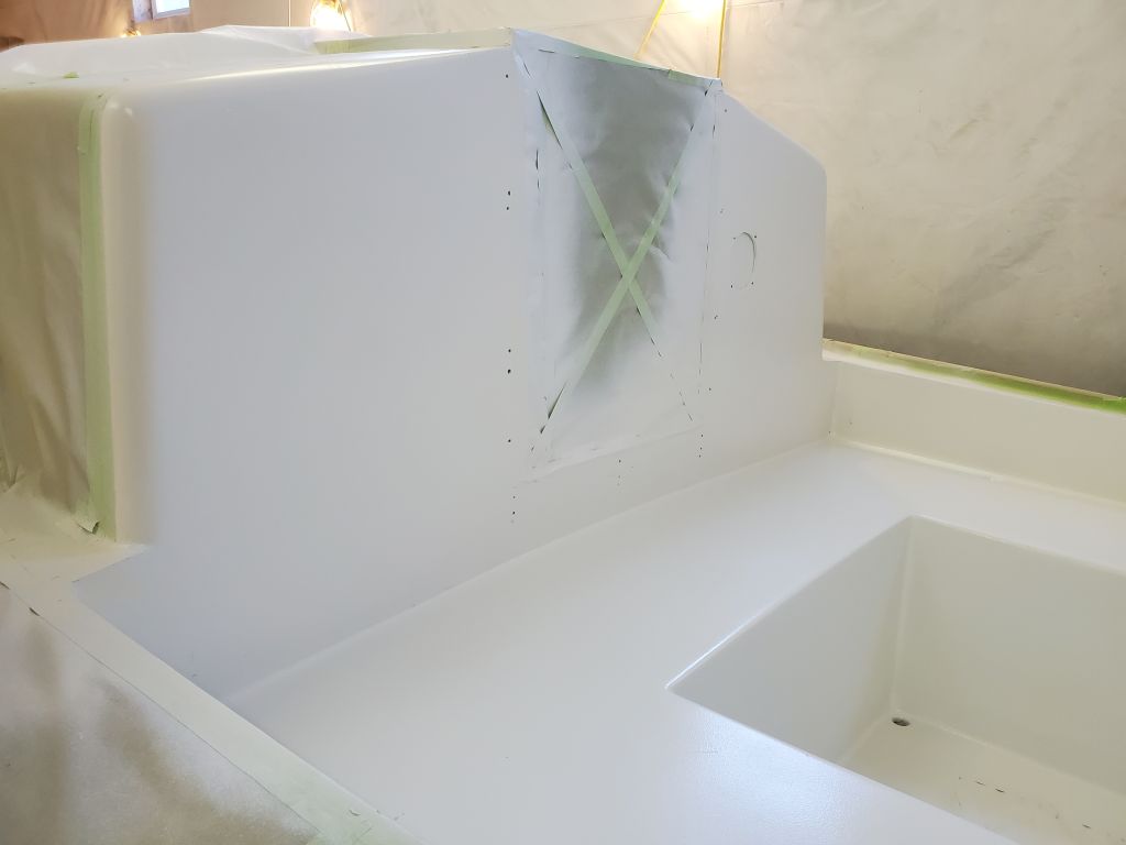
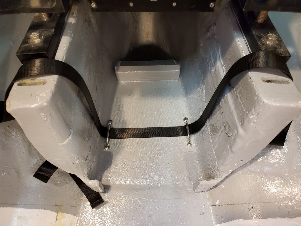
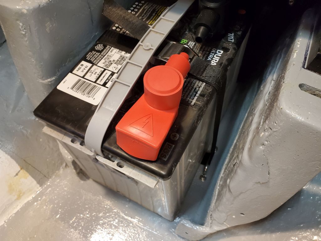
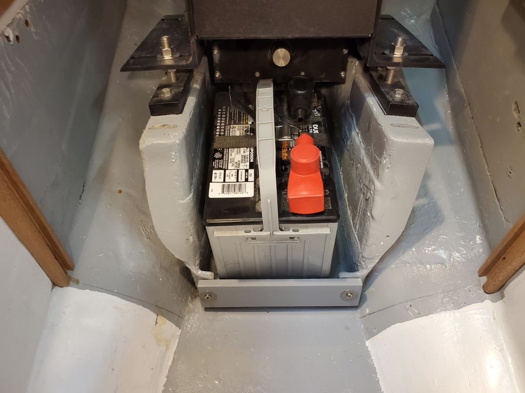
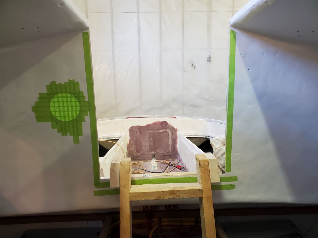
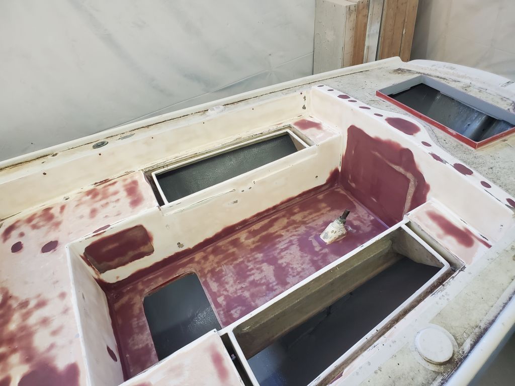
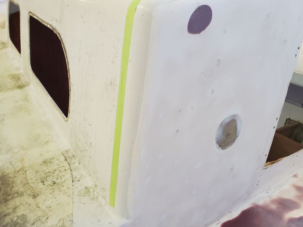
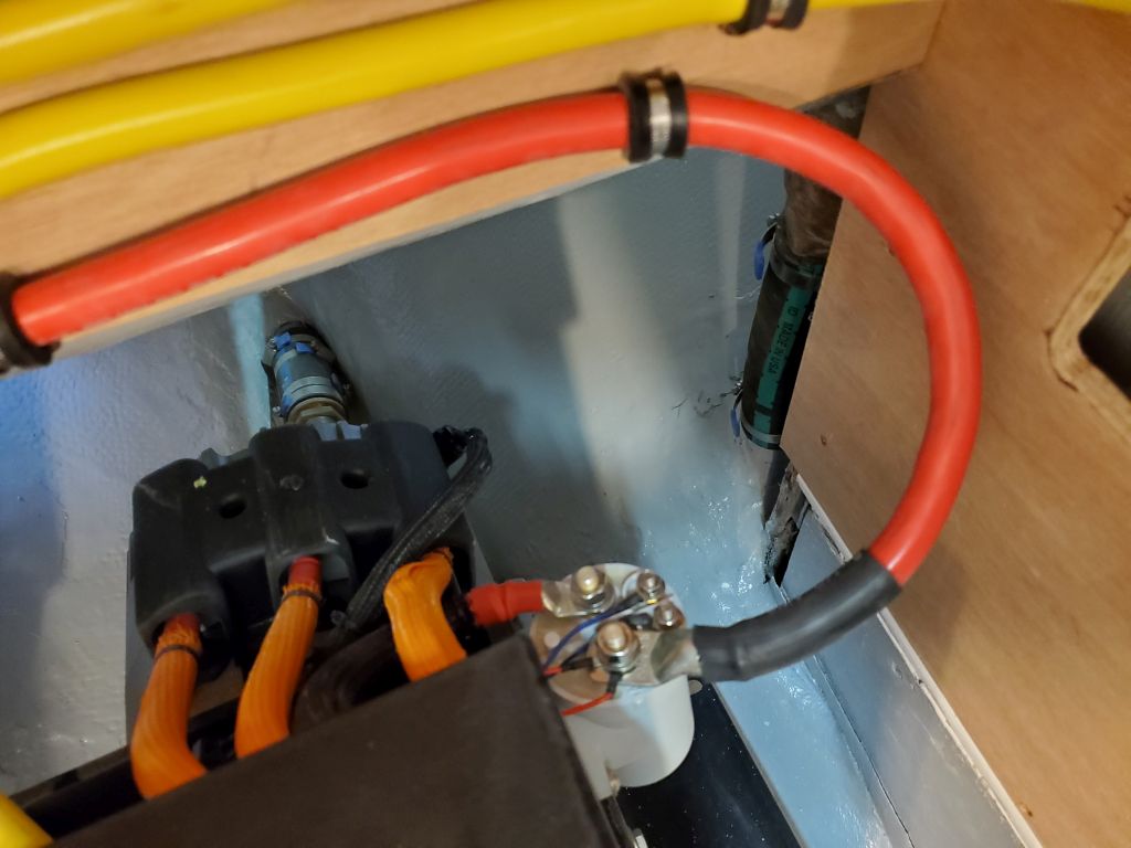
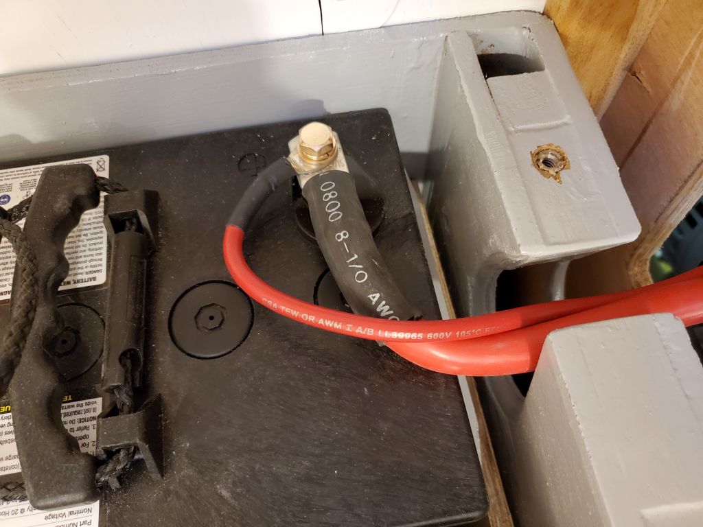
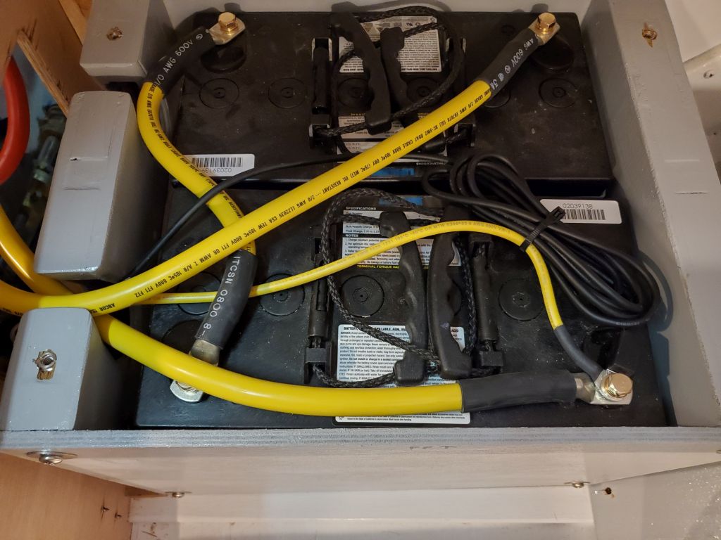
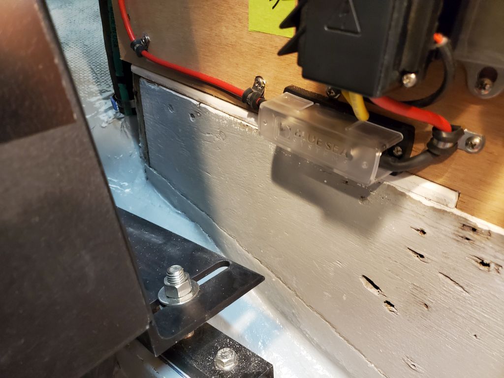
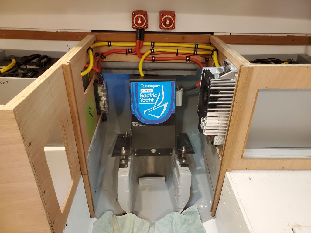
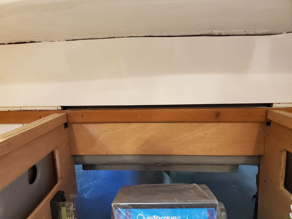
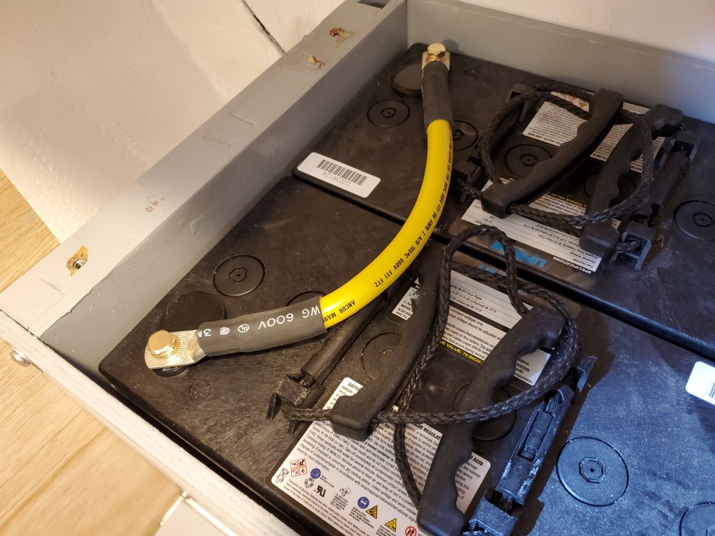
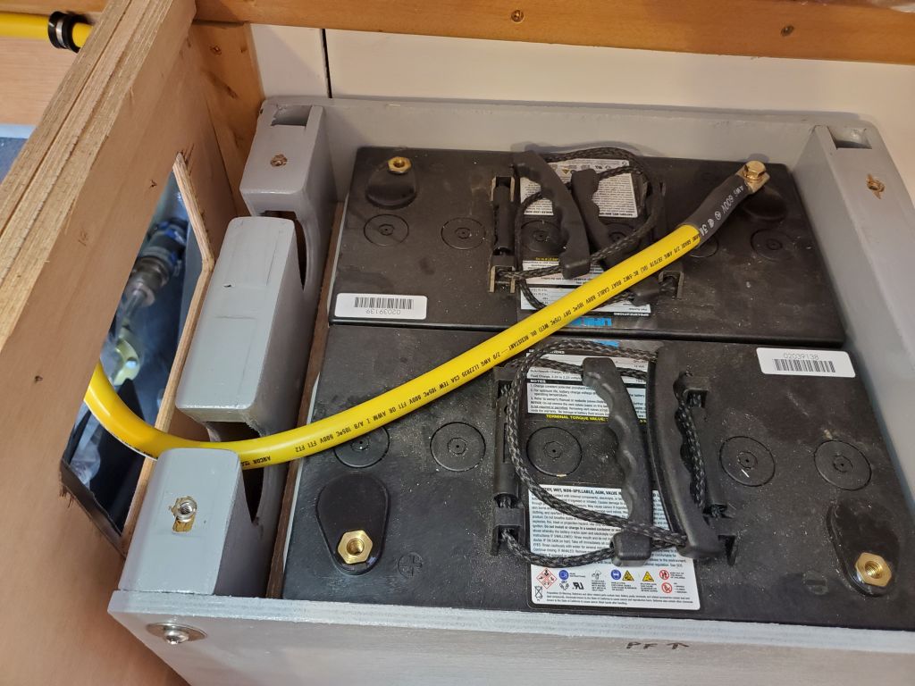
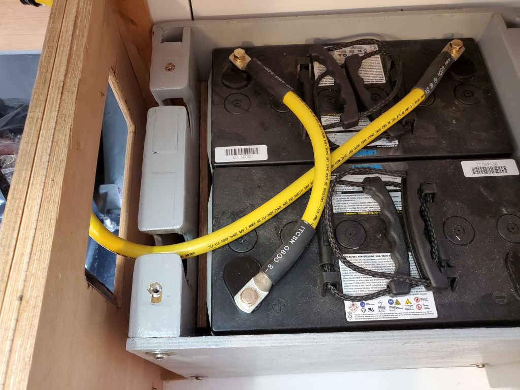
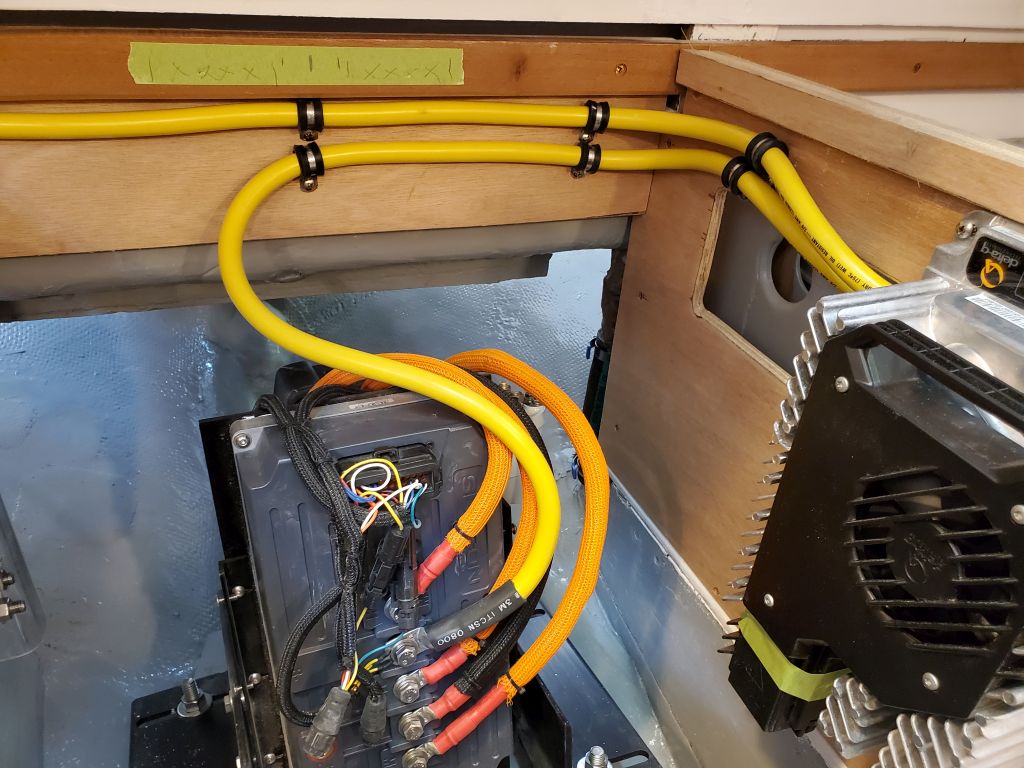
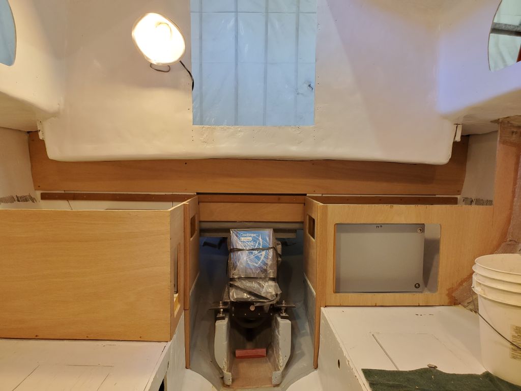
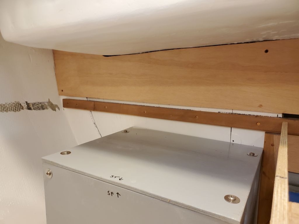
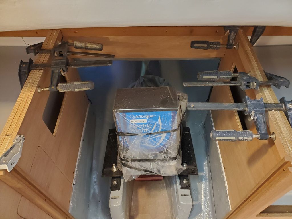
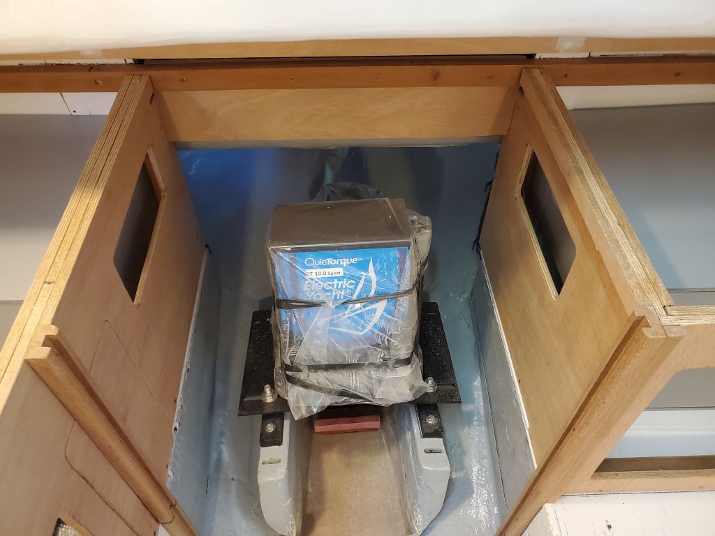
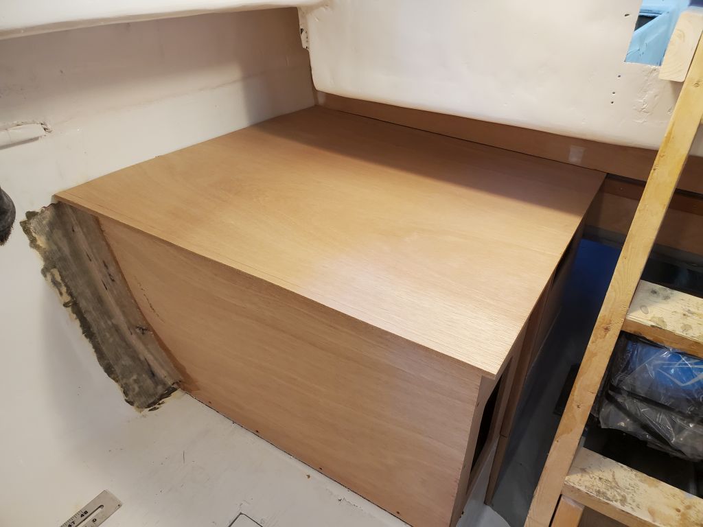
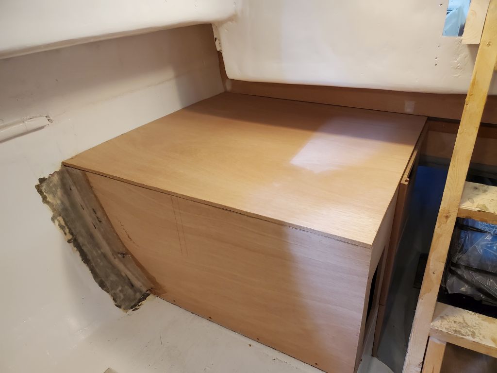
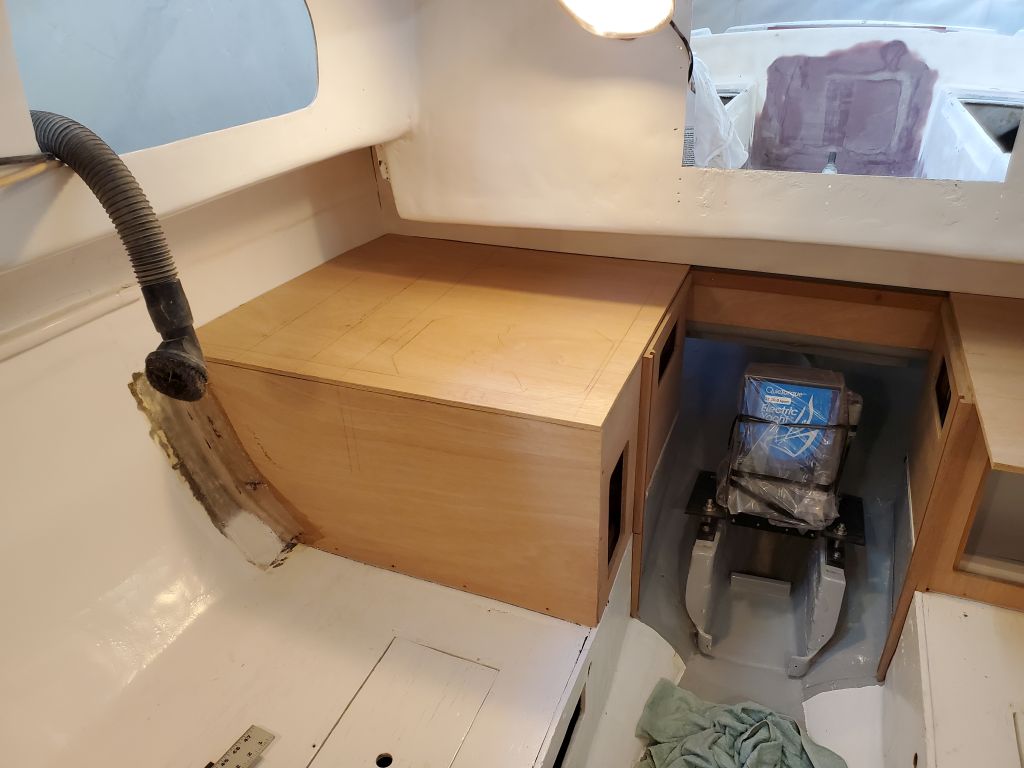
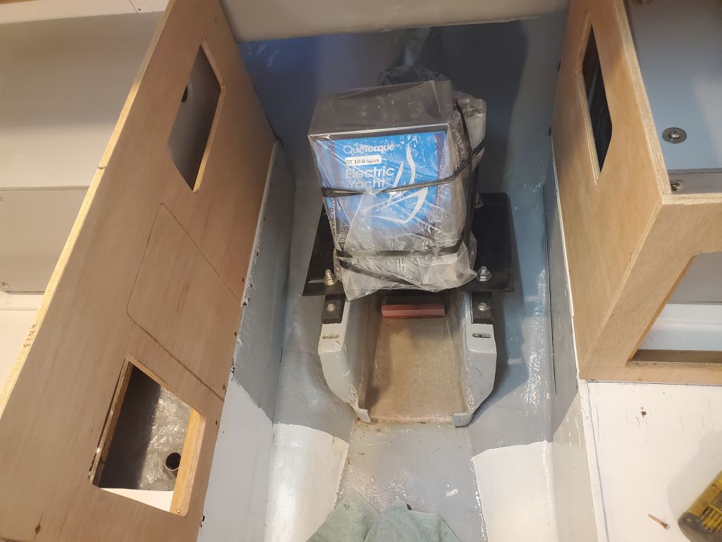
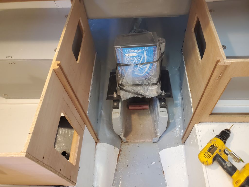
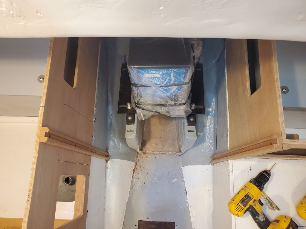
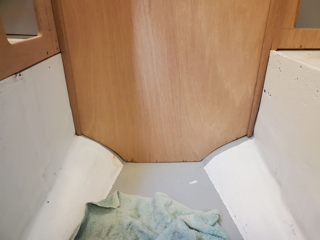
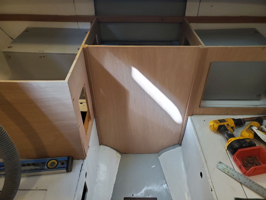
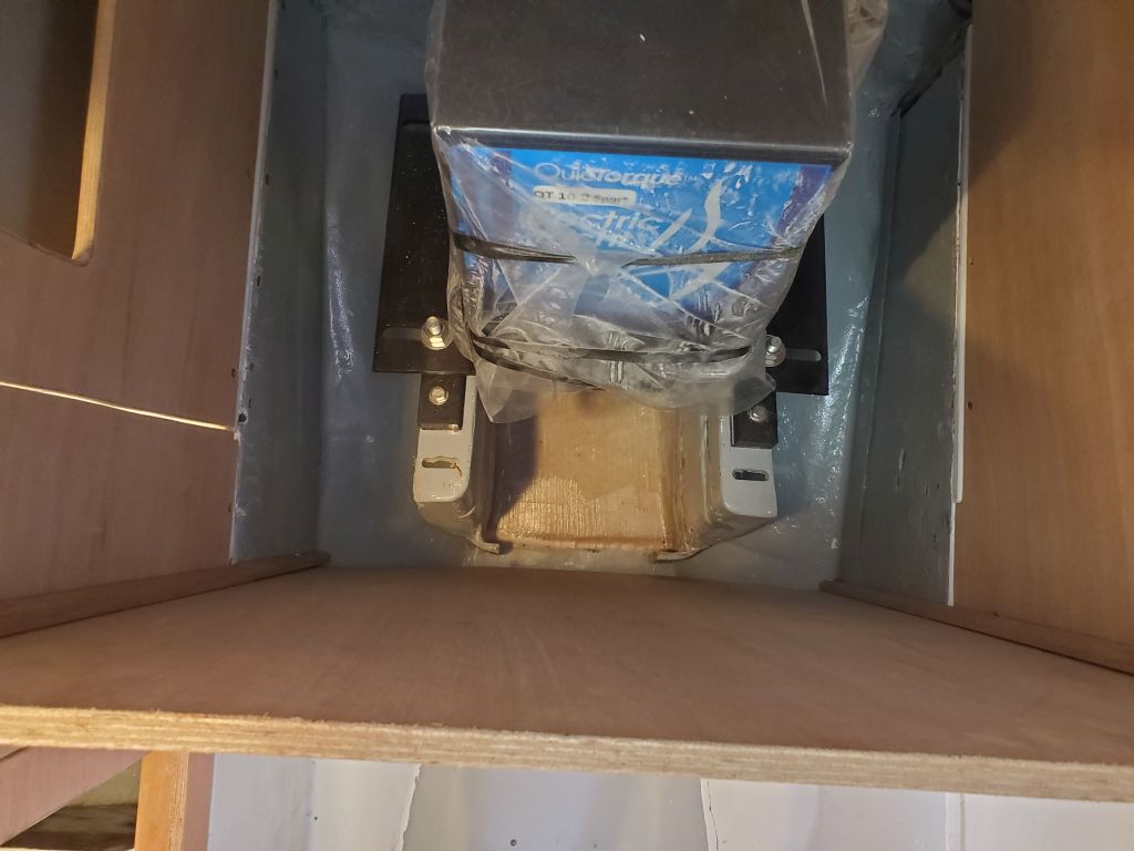
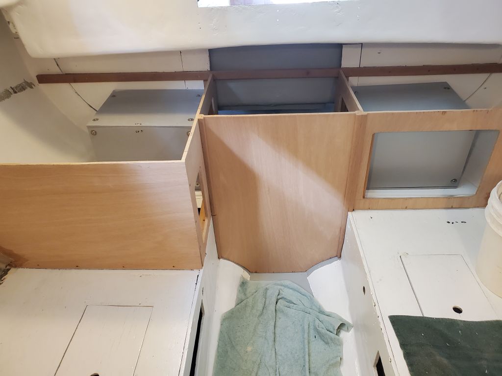
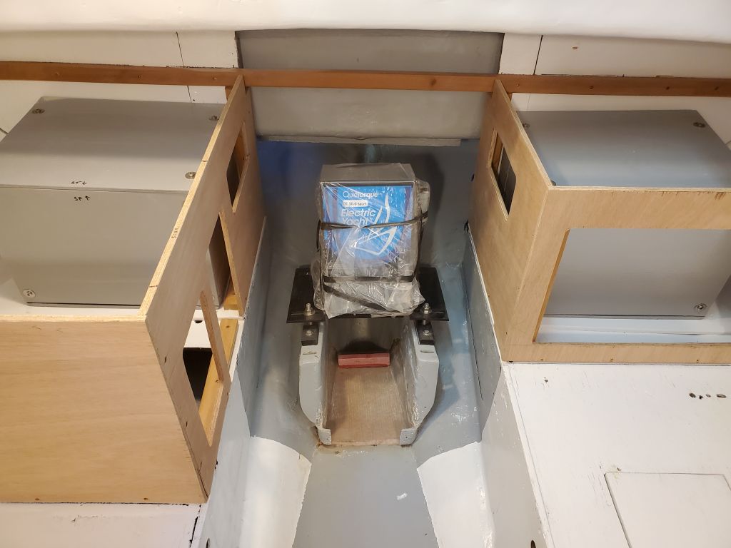
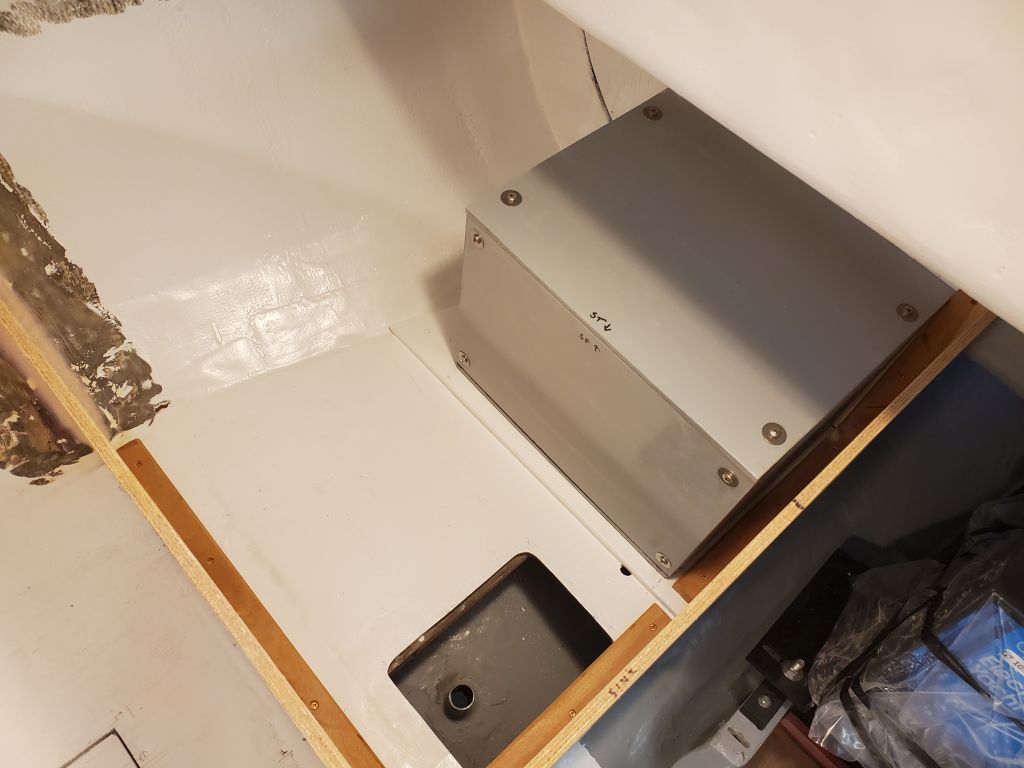
The new engine room front panel finished off the basic galley cabinets, and fit as far aft as practicable to leave as much cabin space available as possible.  There was just enough clearance forward of the engine foundations to allow for the installation of the fiberglass cleat I’d made to secure the house battery beneath the electric motor.

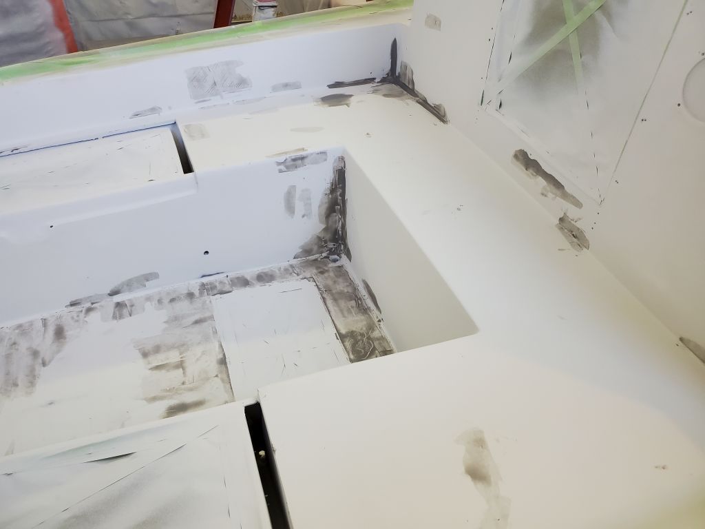
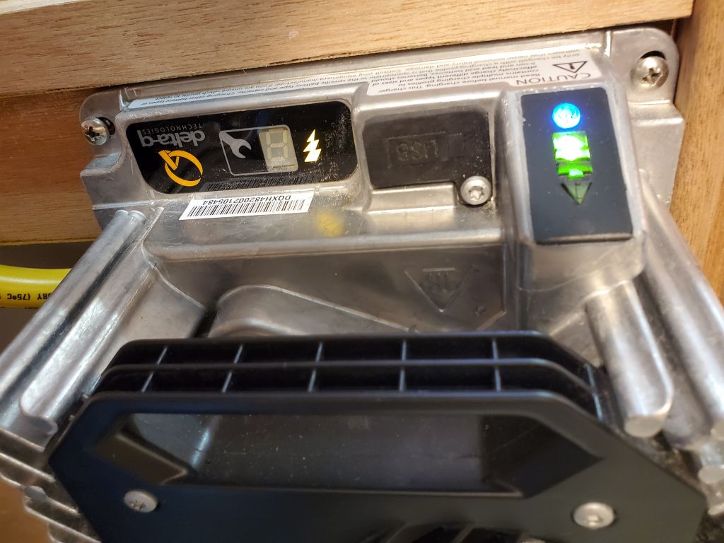
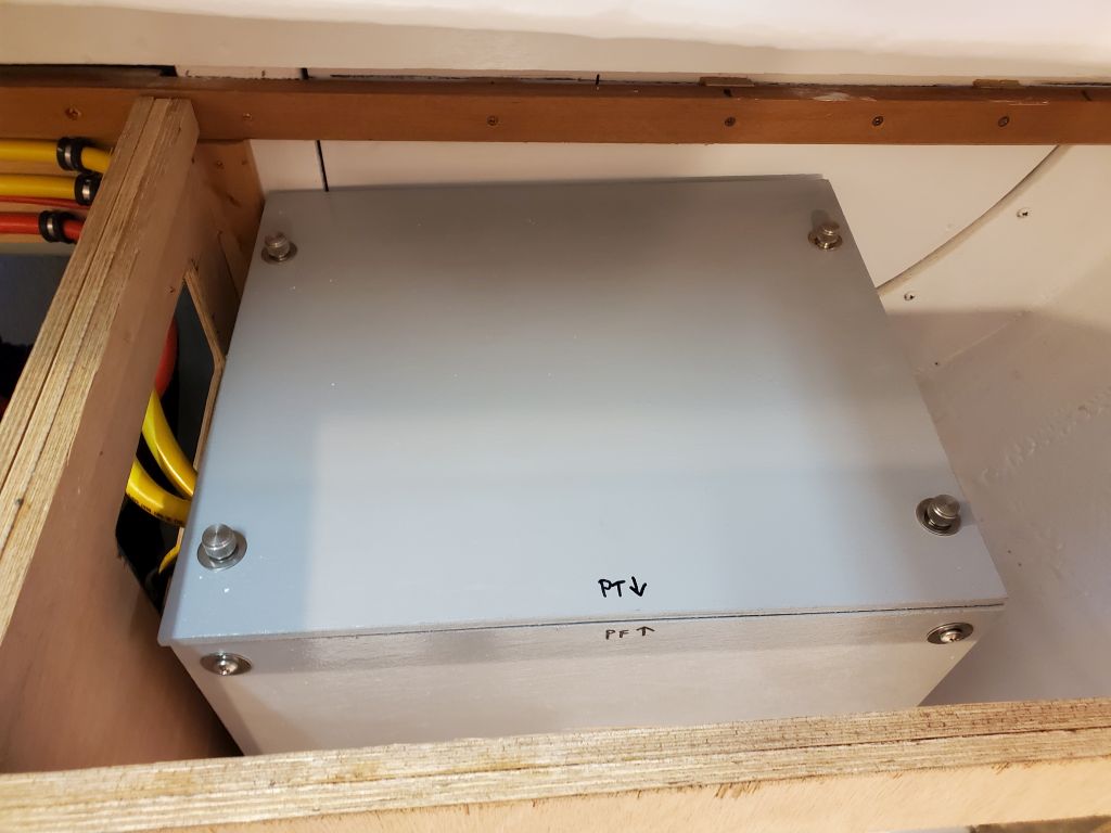
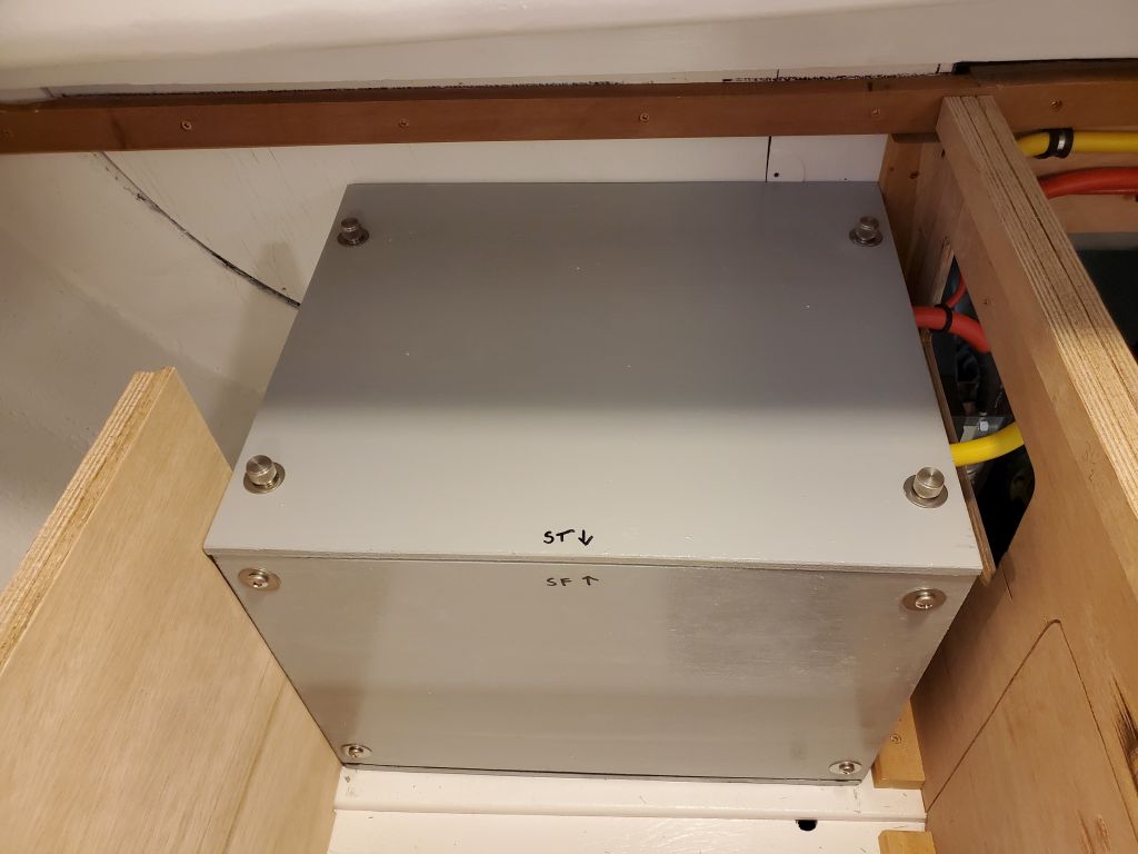
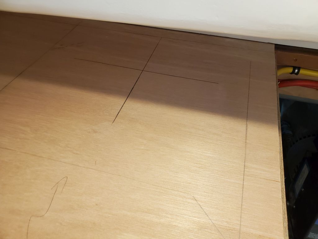
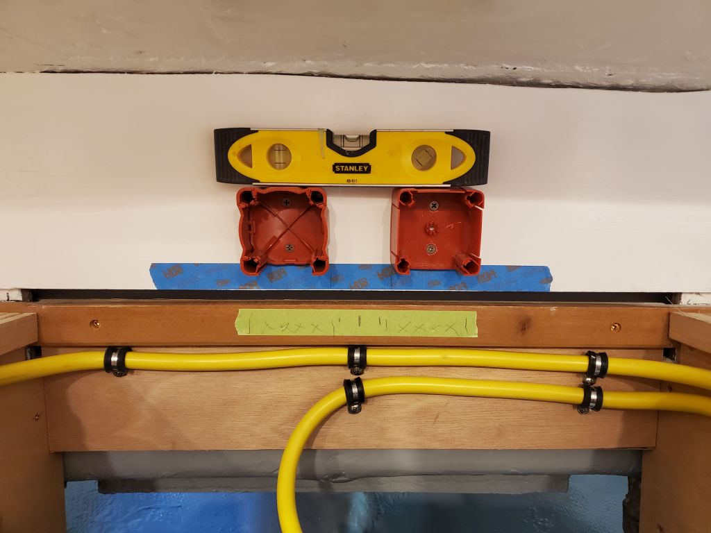
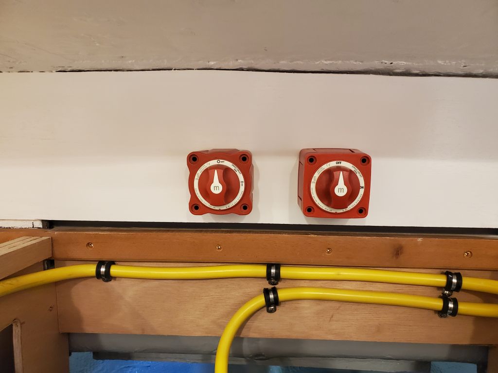
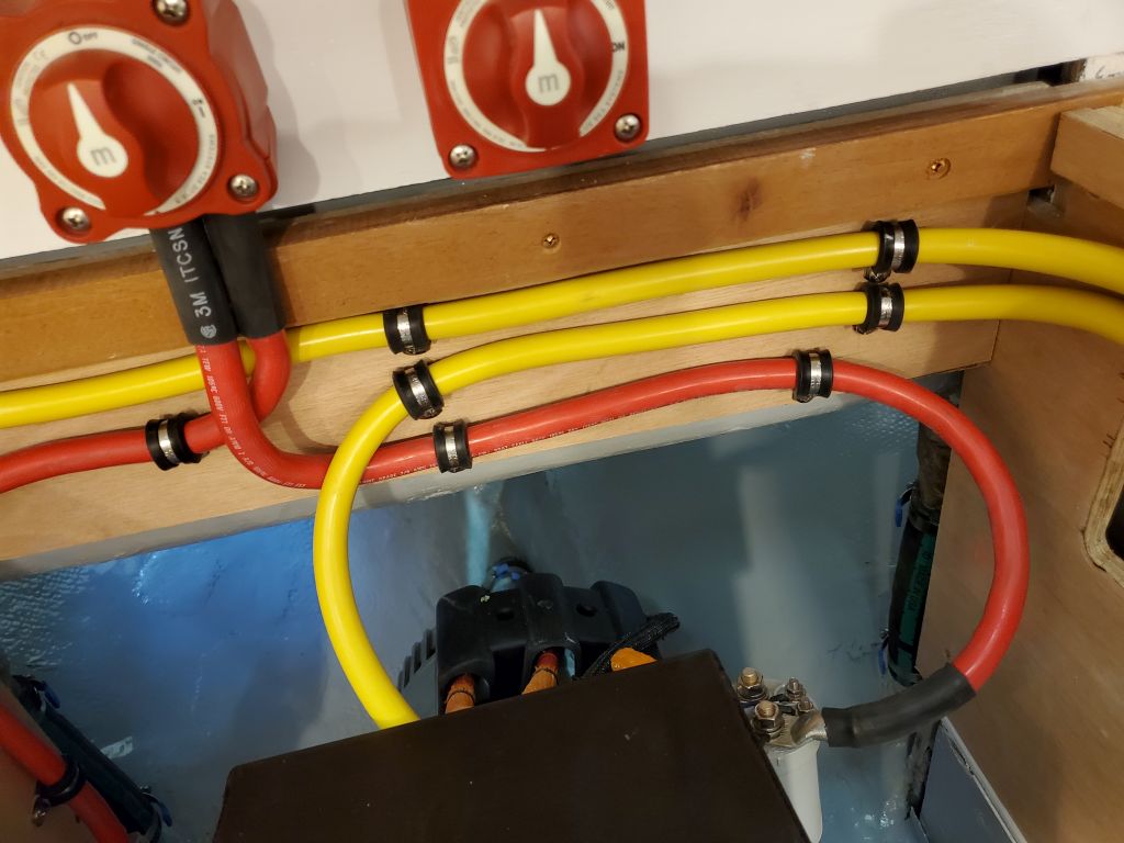
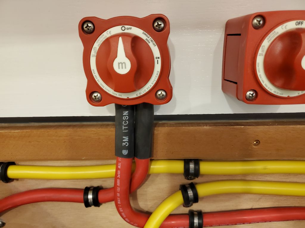
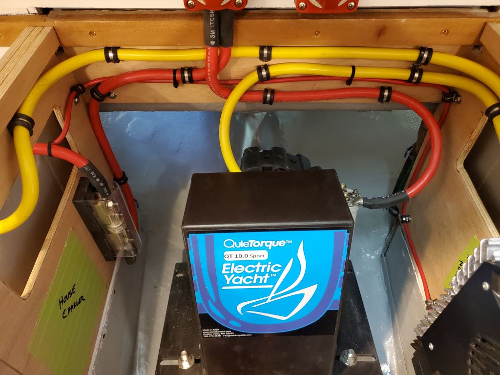
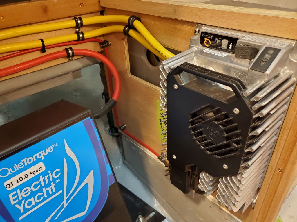
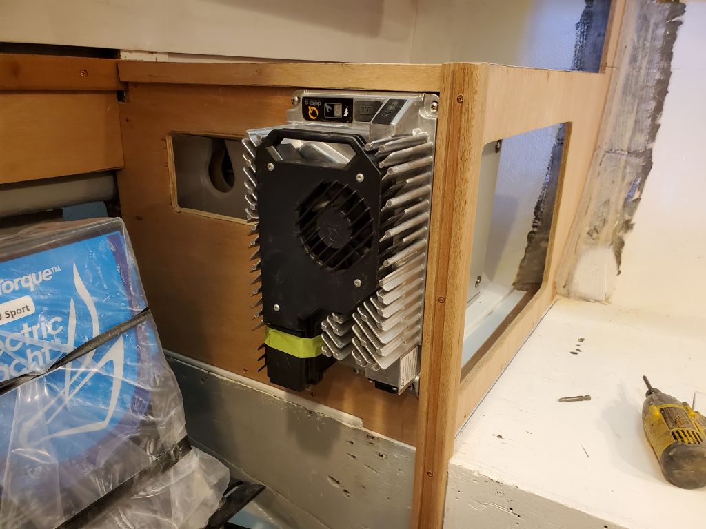
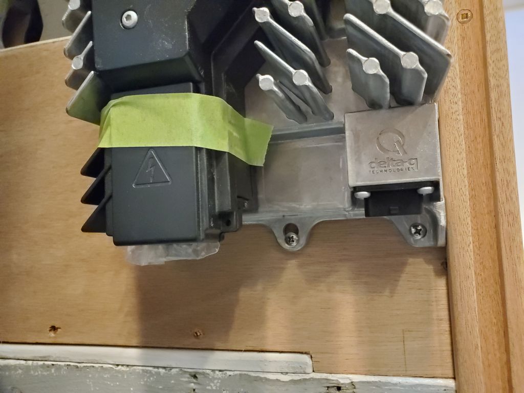
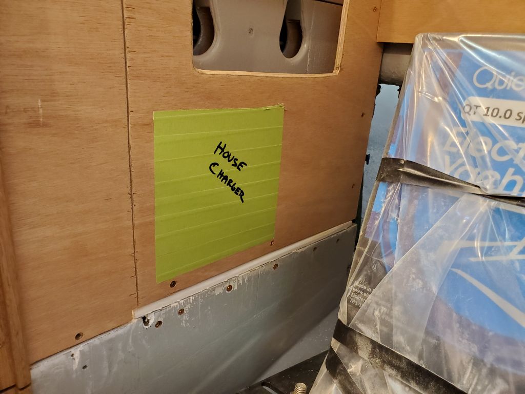
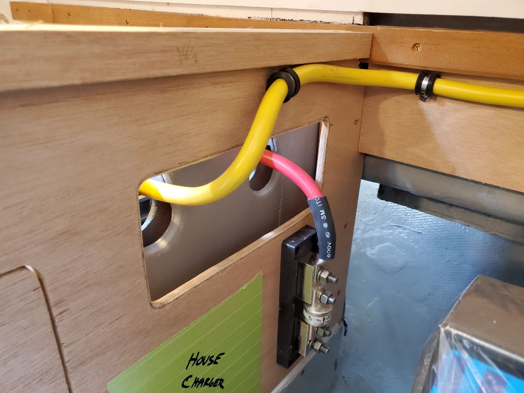
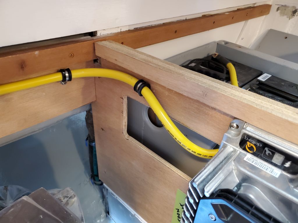
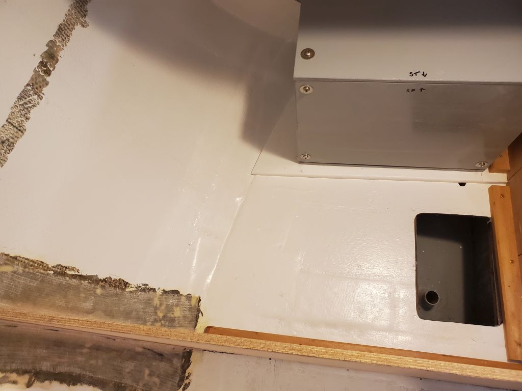
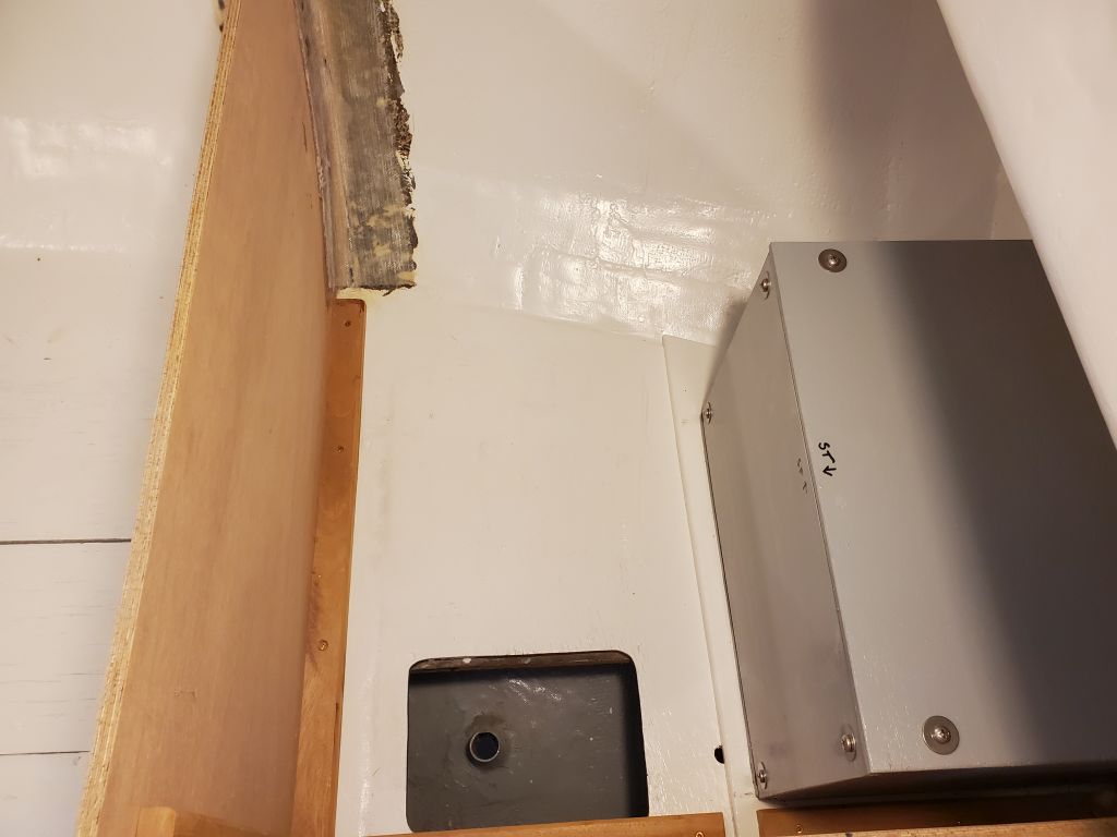
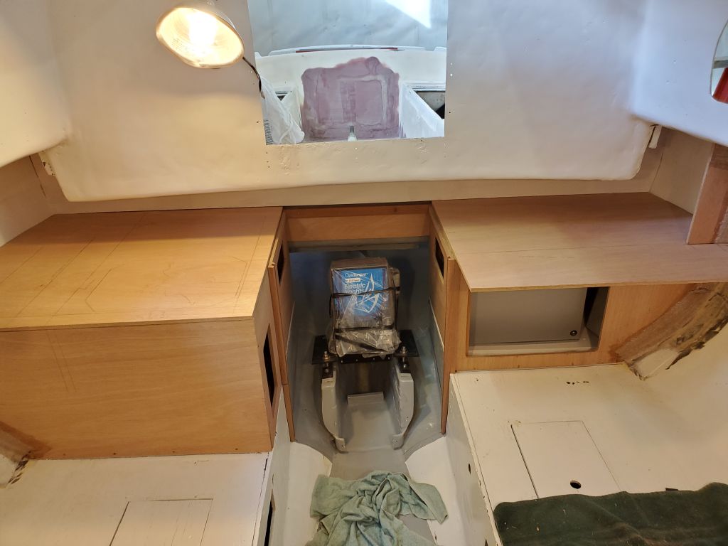
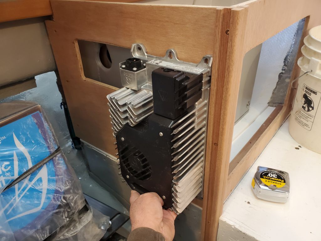
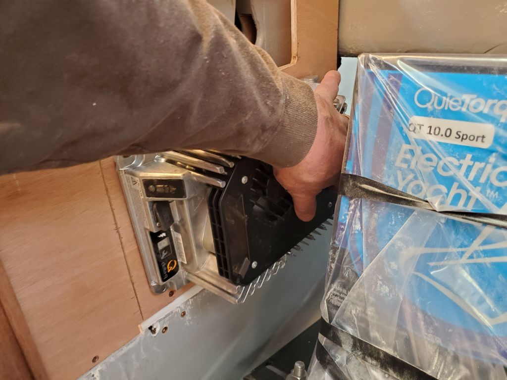
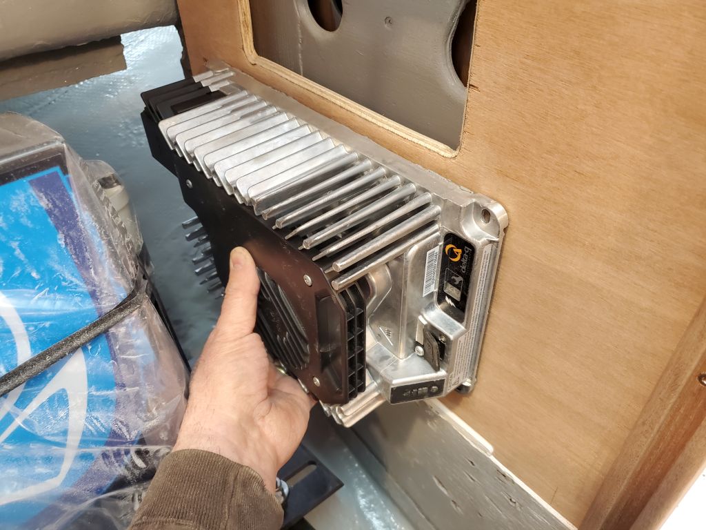
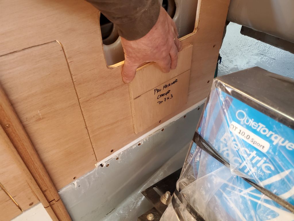
Now it was near the end of the day, but with the engine room now fully defined I could start thinking about the final layout for a pair of battery chargers–one for the 48-volt propulsion bank, and a smaller one (not on hand, but with a plywood stand-in) for the 12-volt house battery.  The engine room seemed the best place for these chargers, and I mocked up a few possible positions for the larger charger for the owner’s consideration.

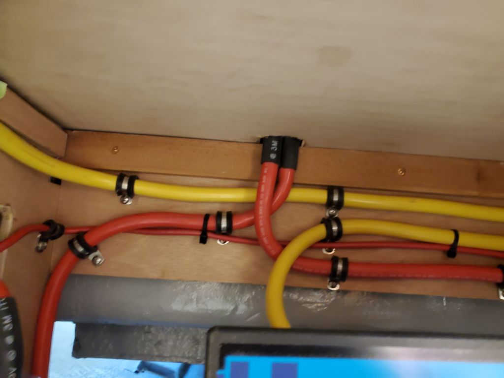
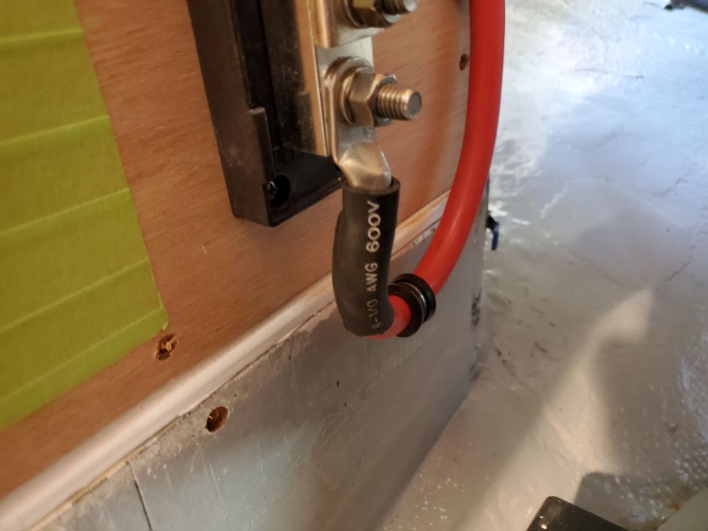
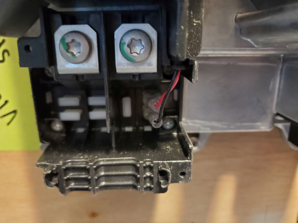
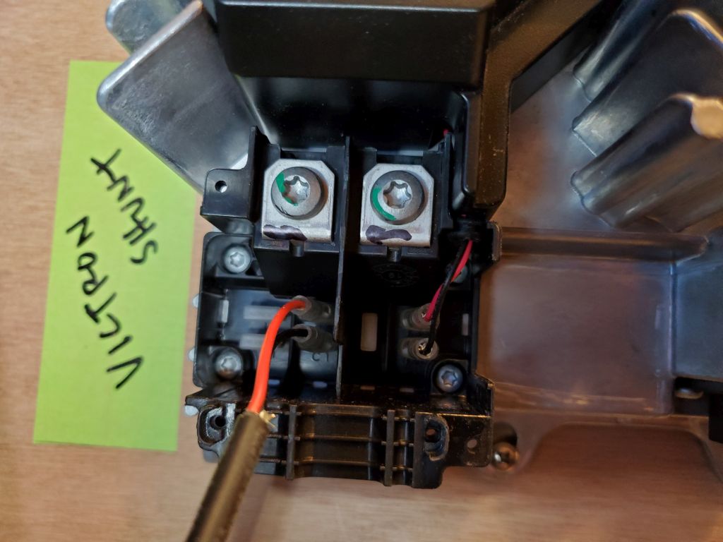
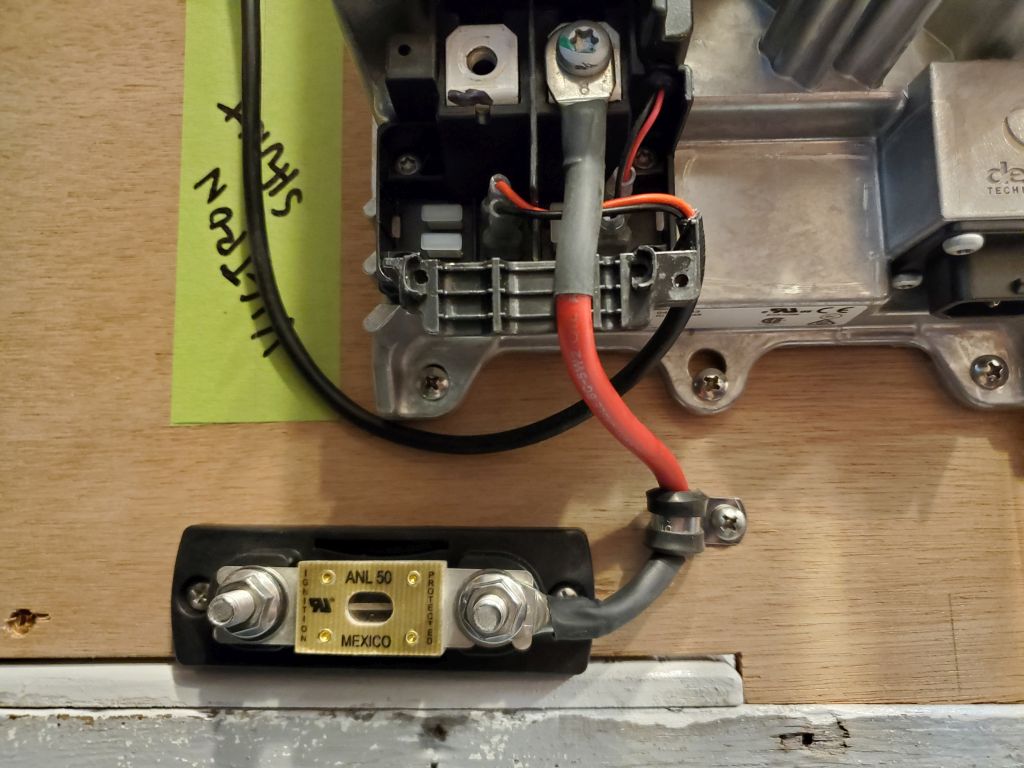
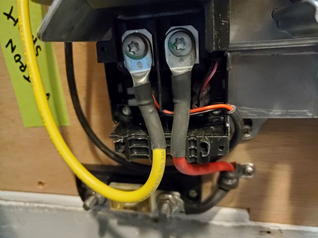
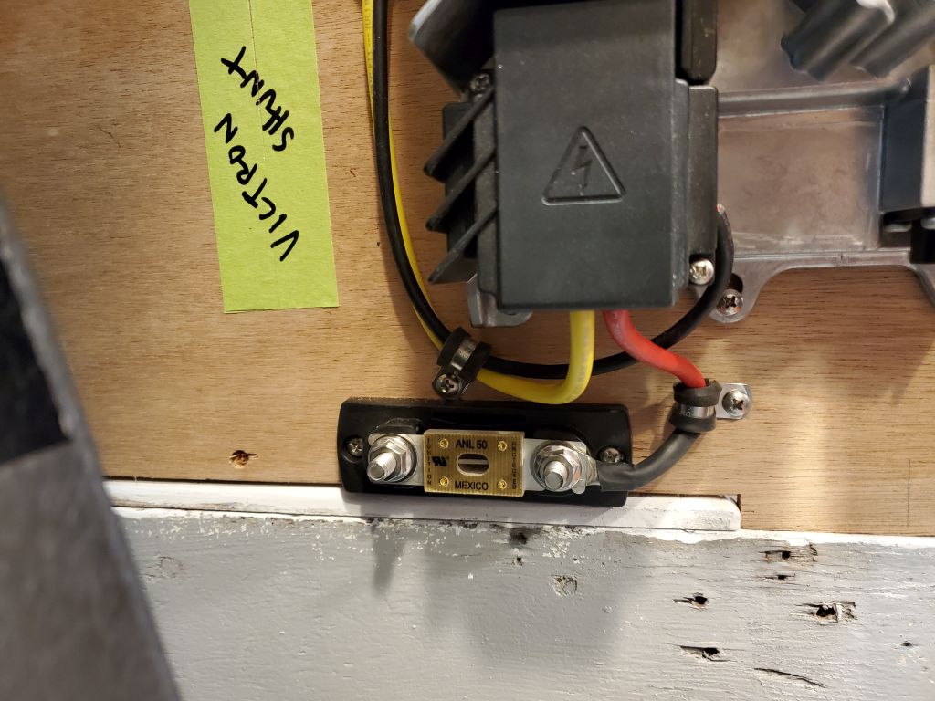
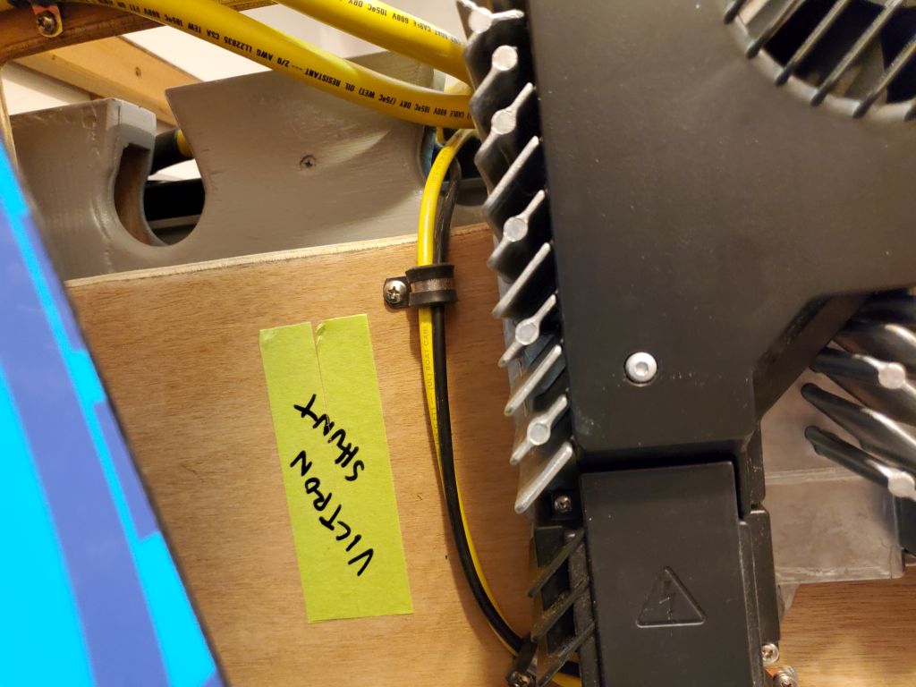
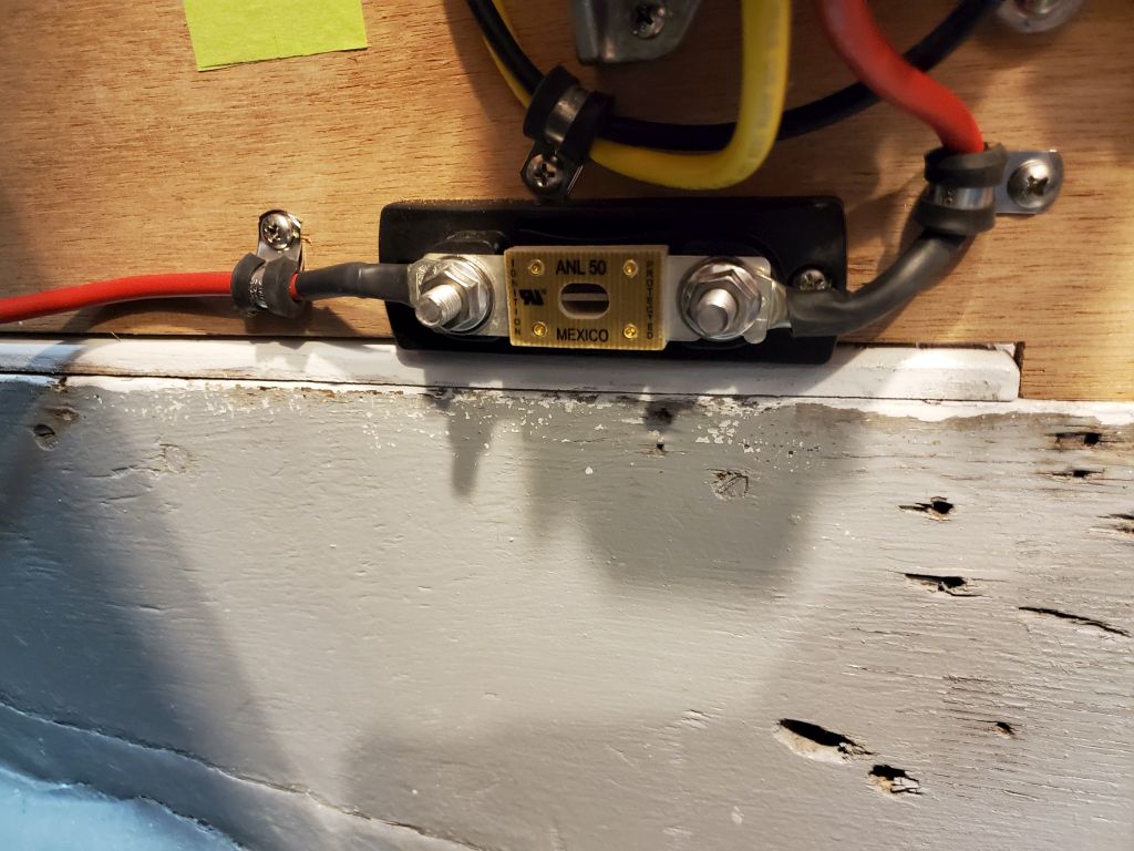
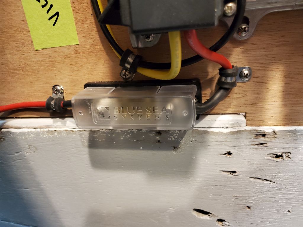
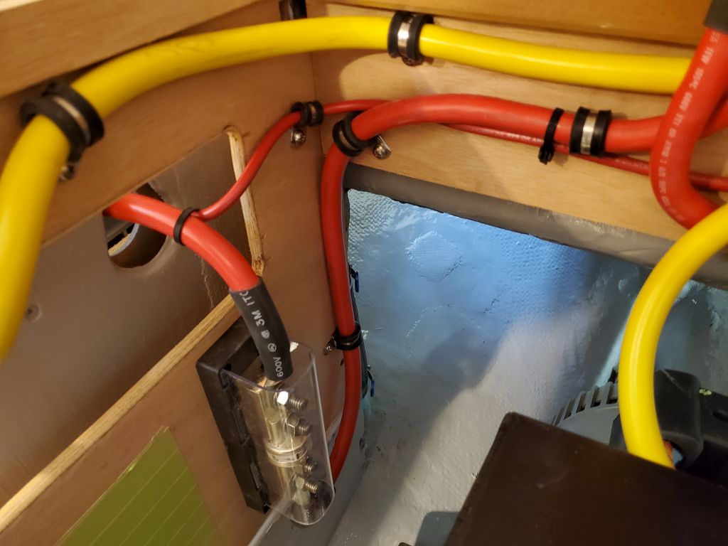
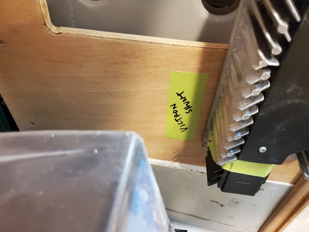
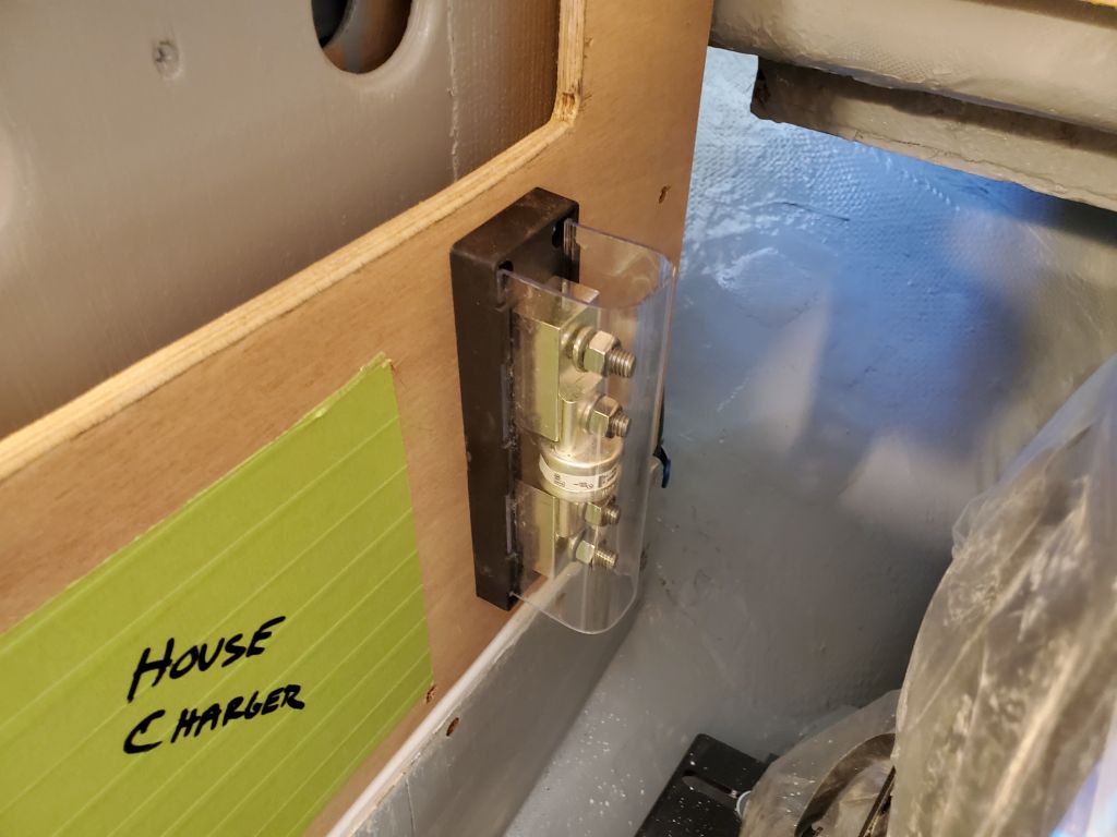
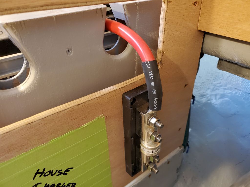
The smaller charger, represented by a scrap of plywood cut to size, would fit in any of the same positions, depending on where the big one ended up, and thus posed no particular installation issues.  Other installations that would compete for the remaining space on these bulkheads included a shunt for a battery monitor, a large main system fuse for the engine bank, wire runs for various cables, and possibly in the future some 110-volt outlets to power the chargers,  I’d account for these and other installations once the chargers were located.

Total time billed on this job today:  5.75 hours

0600 Weather Observation:  8°, clear.  Forecast for the day:   Sunny, windy, 18°

Lyra 37

Friday

The main galley bulkheads were now permanent and sturdy, so now I could prepare to install the two short longitudinal bulkheads to enclose the engine room.  First, however, I water-washed and lightly sanded the new bulkhead fillets to prepare them.

I secured the engine room bulkheads with screws against the various cleats I’d previously installed, so this was a quick process.  For now, I left the removable panels out of the starboard side, as I didn’t know yet how best to install them.

With all the pieces in place, I used my original countertop mockups to create patterns of the countertop, accurately marking the hull, aft bulkhead, and other bulkheads on the patterns for later use in creating the final countertop.  The owner and I had discussed an extension forward of the port bulkhead, which would be easy enough to accommodate, and to prepare for this I also made a template extending to the hull forward of the bulkhead there, to allow for the possibility of bringing the extension straight to the hull and to likely define the bottom of the electrical locker.  I set these patterns aside for the moment.

Continuing with the bulkheads, I cut sections of 6″ biaxial tabbing to fit both sides of both bulkheads and, after other final preparations, finished up the fillets in the areas where I’d had glue blocks during the initial installation.  Then, I installed the tabbing in epoxy resin.

To round out the day, I transferred my cardboard patterns to a sheet of plywood to use for the exposed area of the aft bulkhead, above the eventual countertop.  I had to turn to another project at the shop, so cutting out the shape would await another time.

Total time billed on this job today:  3.25 hours

0600 Weather Observation:  45°, clear.  Forecast for the day:   Sunny, 50°

Older posts Newer posts