(page 2 of 4)

Dharma Rose 25

Monday

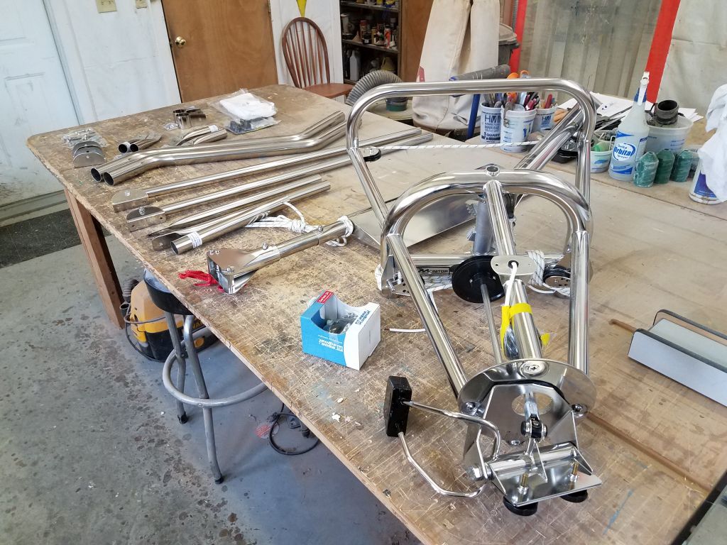
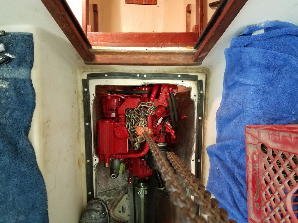
Next on my agenda was the Monitor windvane installation.  I began the day by reading through the instructions and reviewing notes from an earlier installation I completed a couple years earlier.  The basics of the installation were straightforward–just four mounting points on the boat herself–but the key to the installation was positioning the vane correctly, and then suspending it magically in midair while determining the final positions of the four mounts and support tubes.

Sky hooks would be nice.

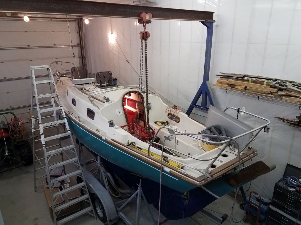
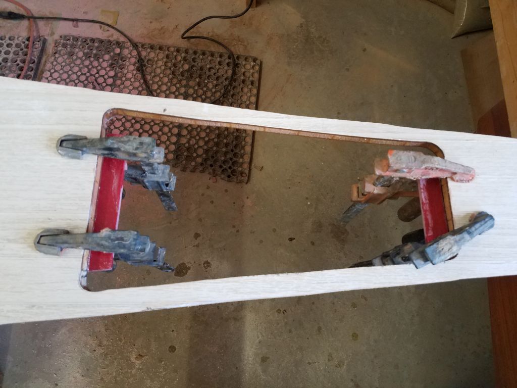
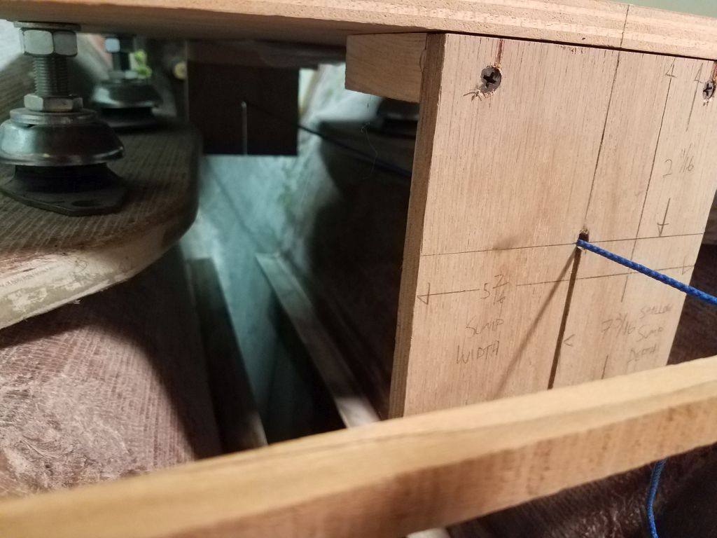
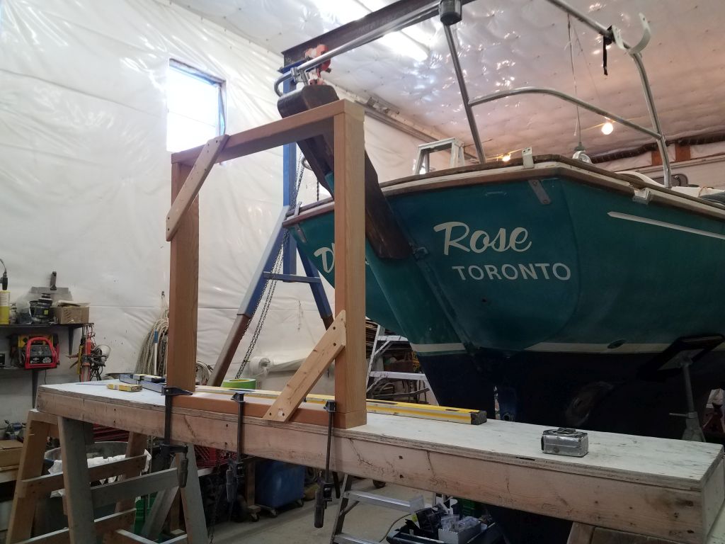
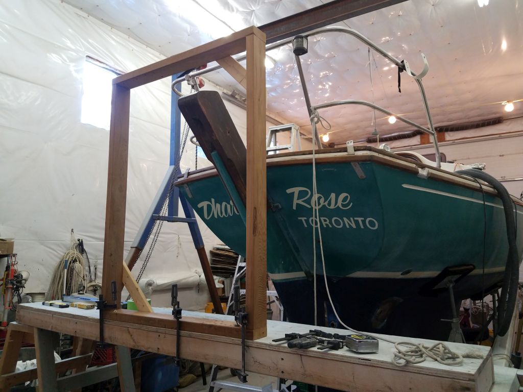
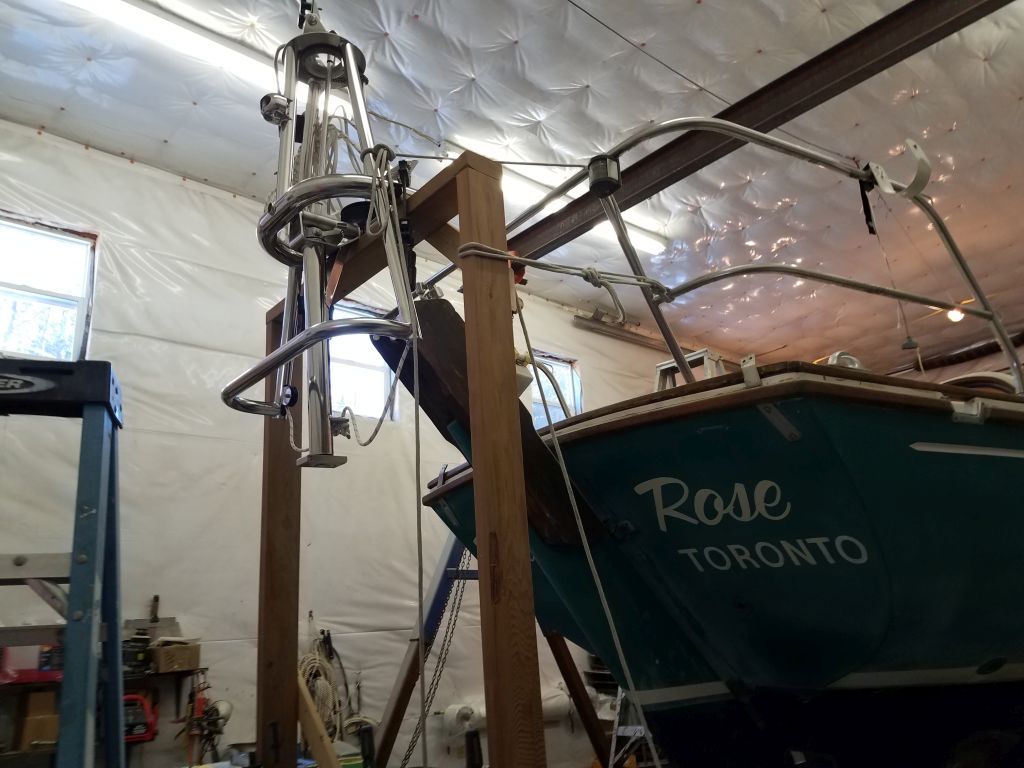
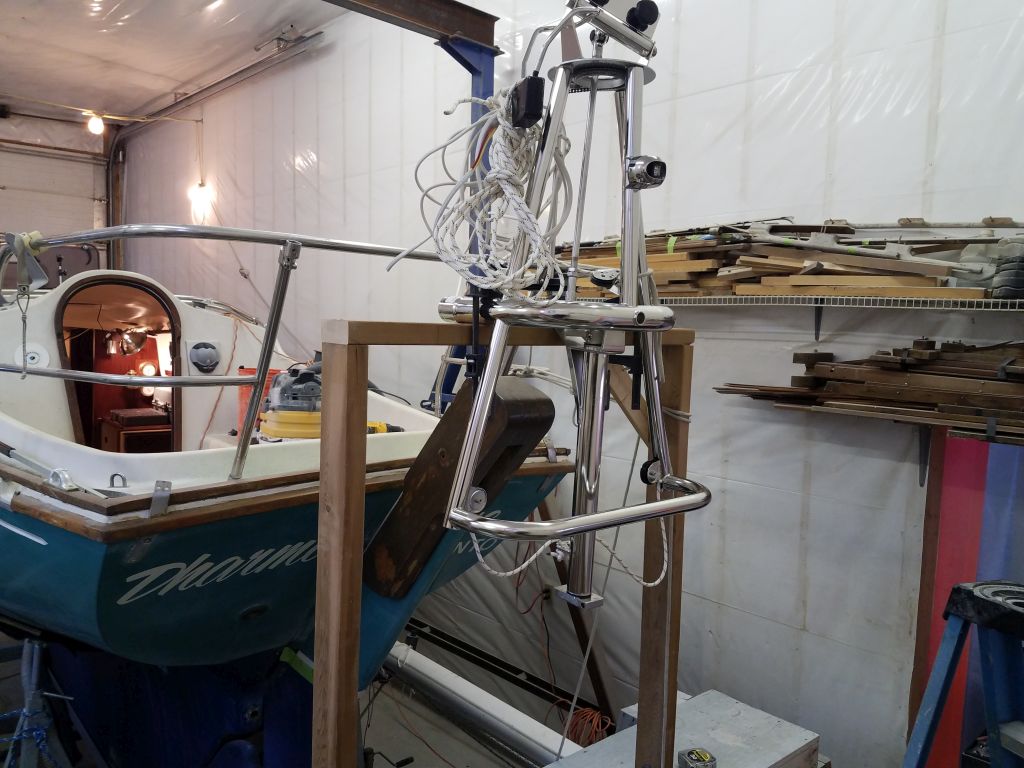
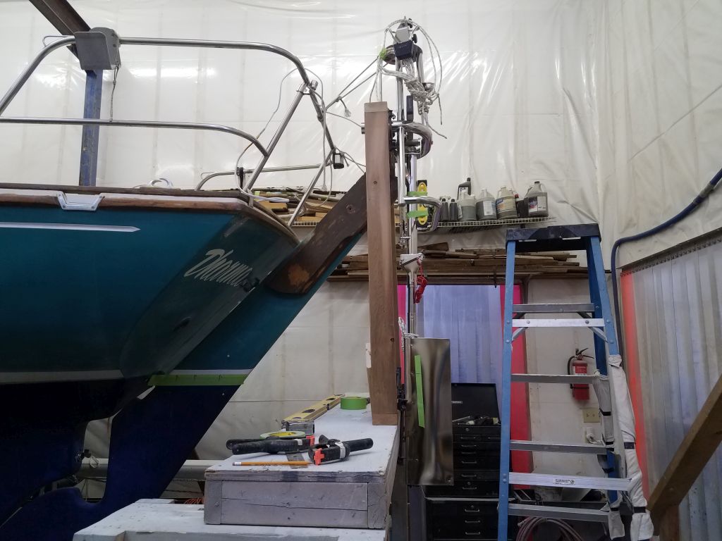
The Contessa 26 makes for perhaps one of the more challenging installations, mainly because the design of the boat, with outboard rudder, steeply-raked transom, and low freeboard meant that the windvane frame required particularly long support tubes, and also needed to be positioned above deck level and well aft to clear the raked rudder cheeks.  So to position the frame correctly and support it during installation, I chose to build a basic support structure to hold the frame at the correct height.  My support started with a staging plank that I set up just aft of the boat, giving me a starting height of just over 5 feet.

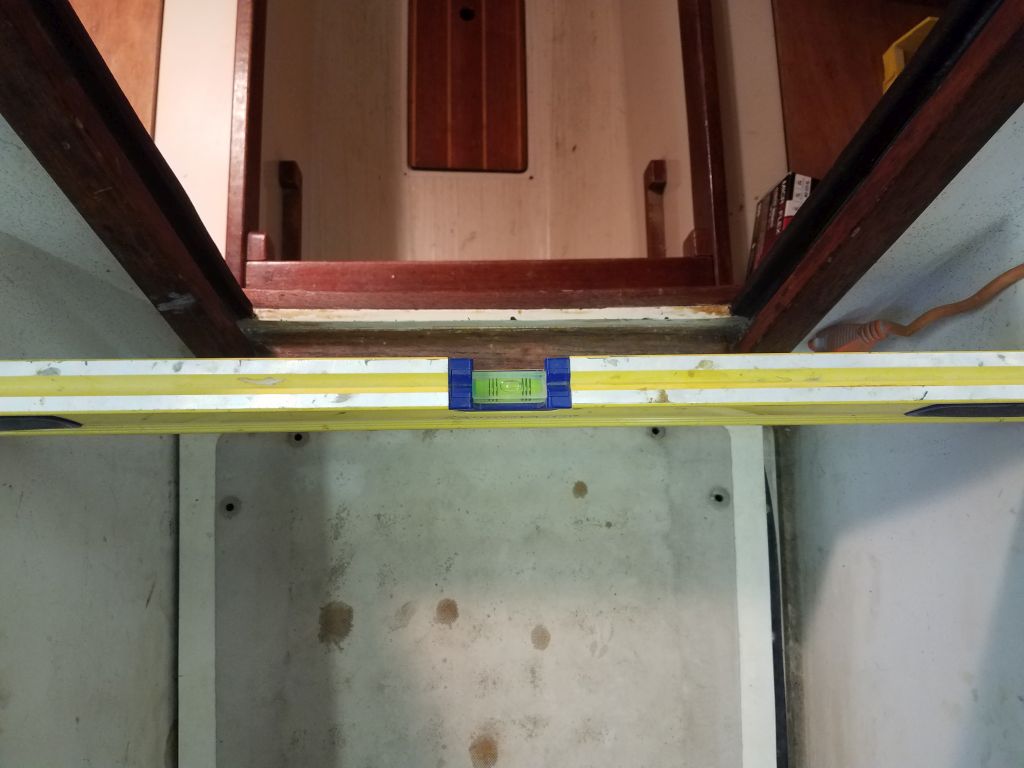
Before beginning the installation, I checked the boat for level and slightly adjusted the stands in correction as needed.

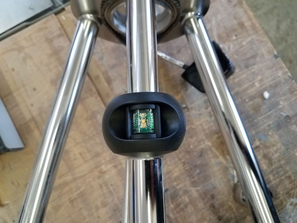
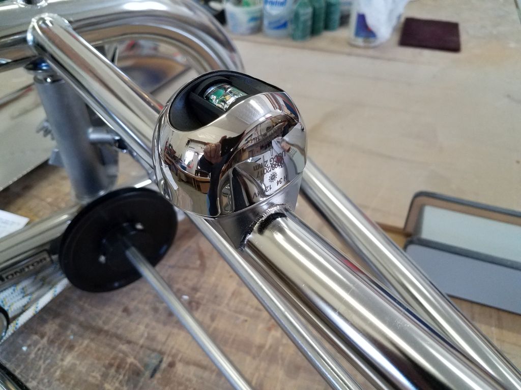
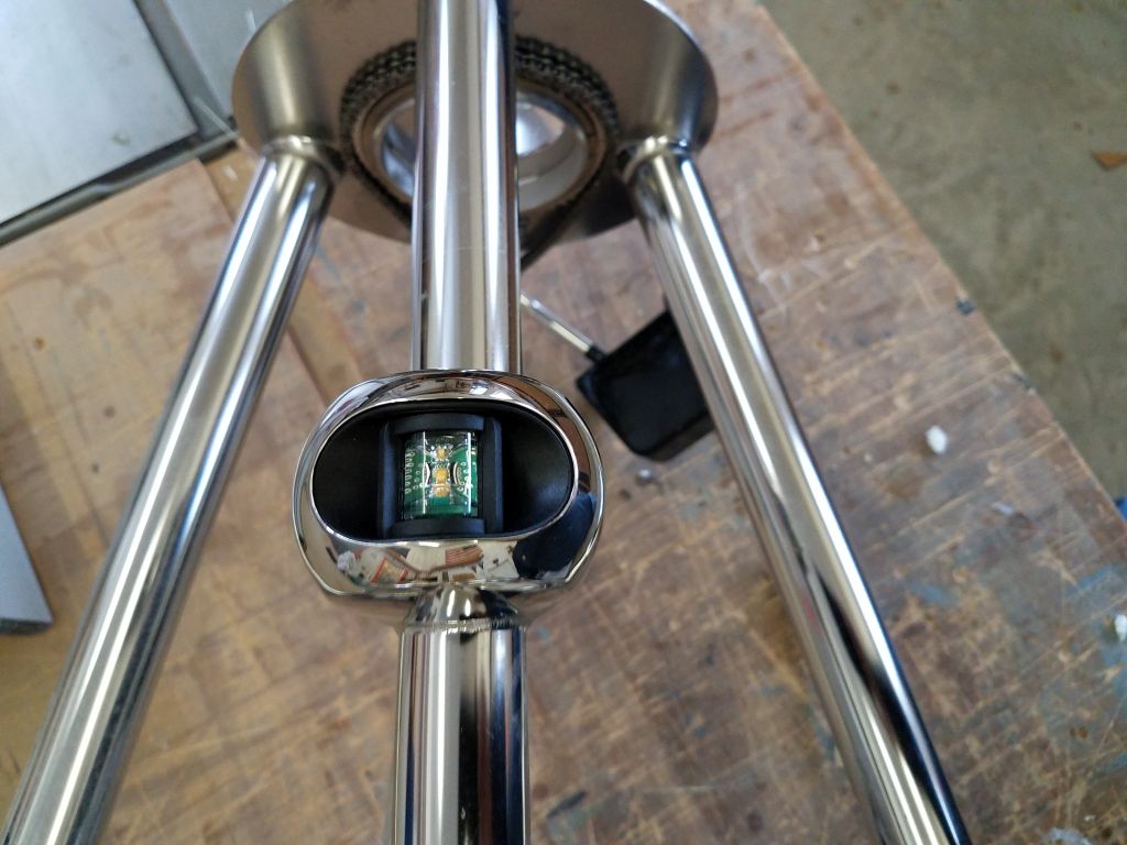
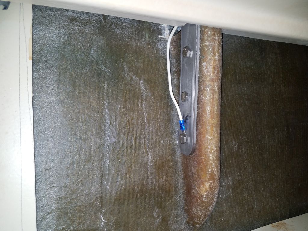
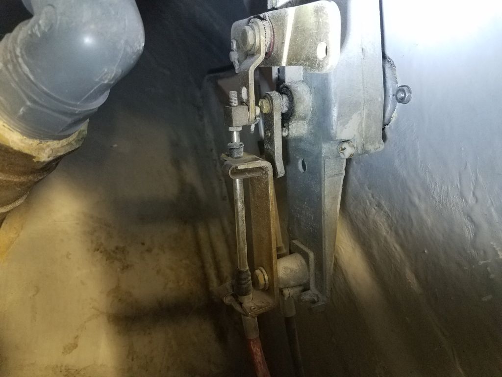
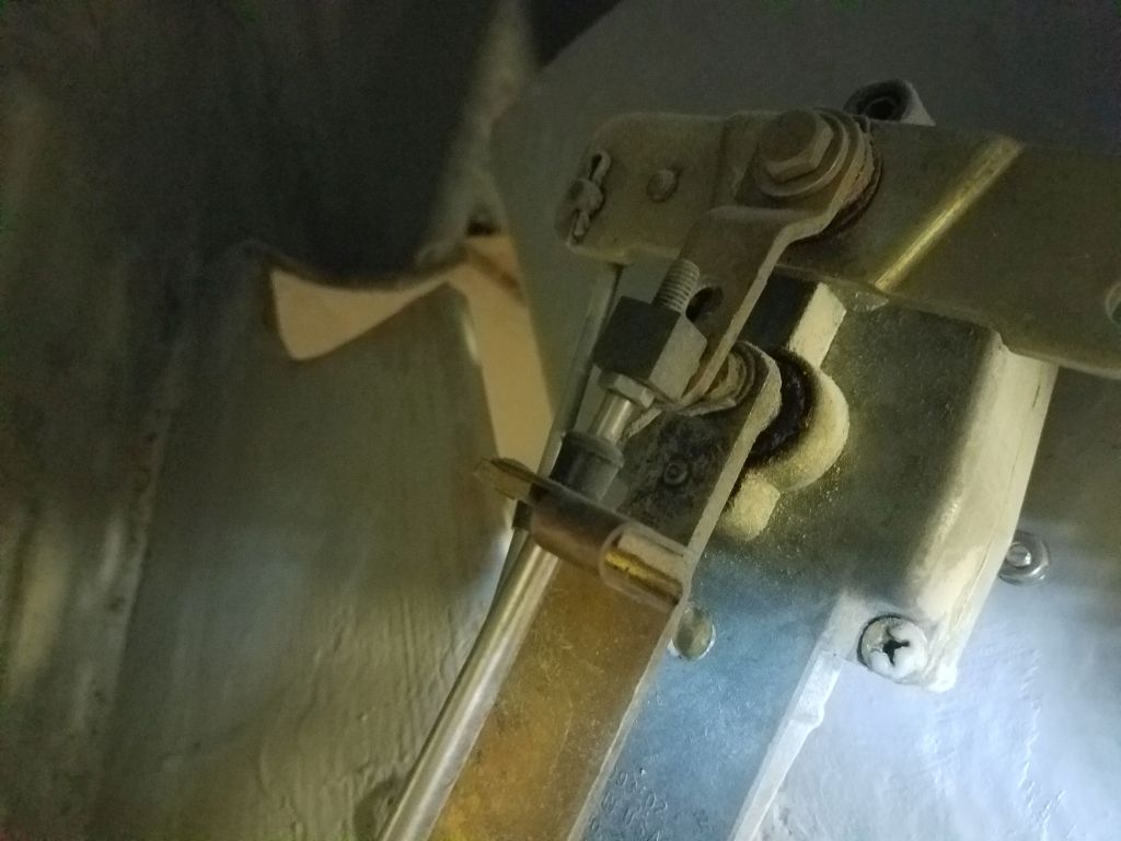
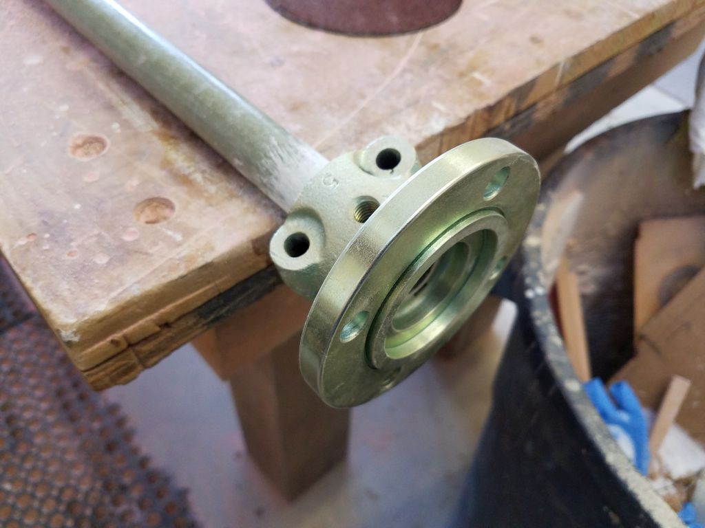
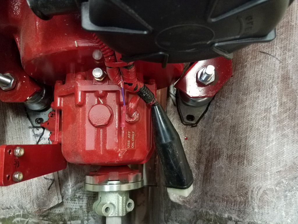
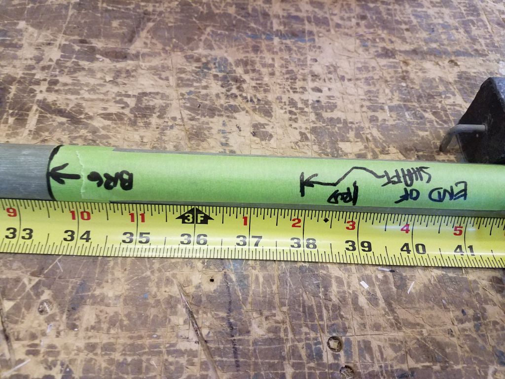
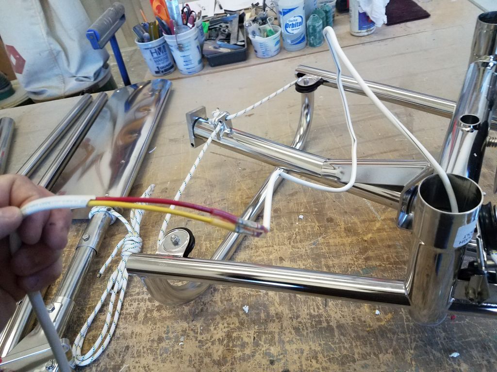
The wire from the stern light on the vane would not be long enough to extend all the way through the long main support tube in the final installation, so I added a length of wire that would be sufficient to complete the wiring connections later.

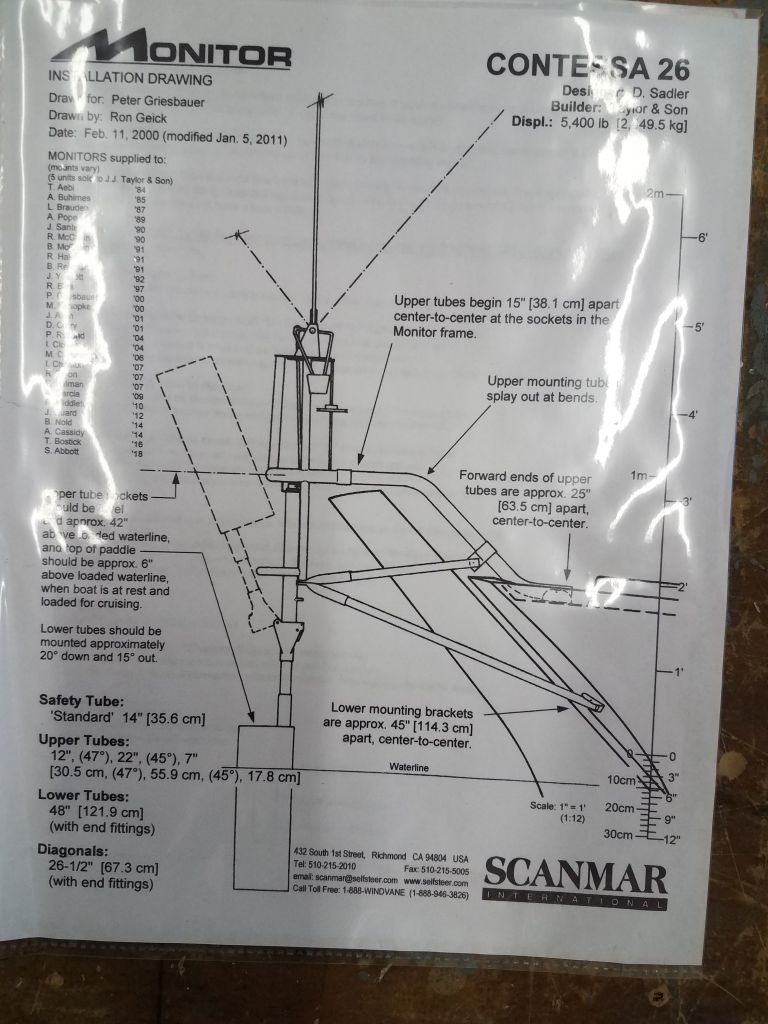
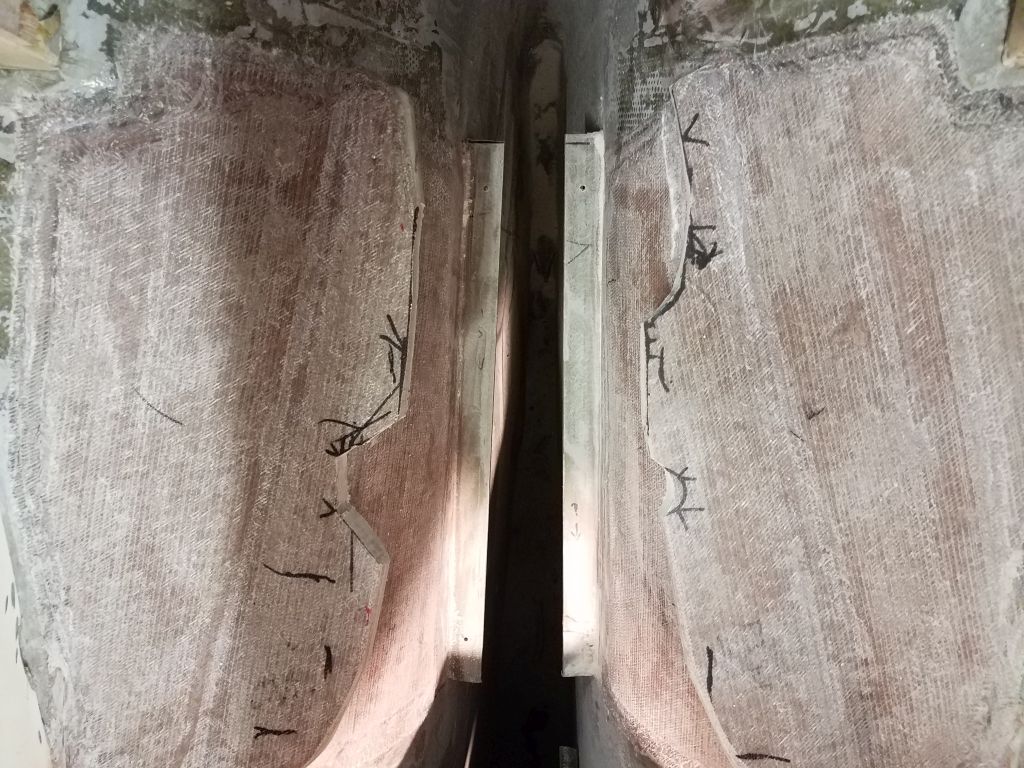
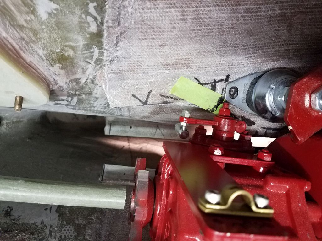
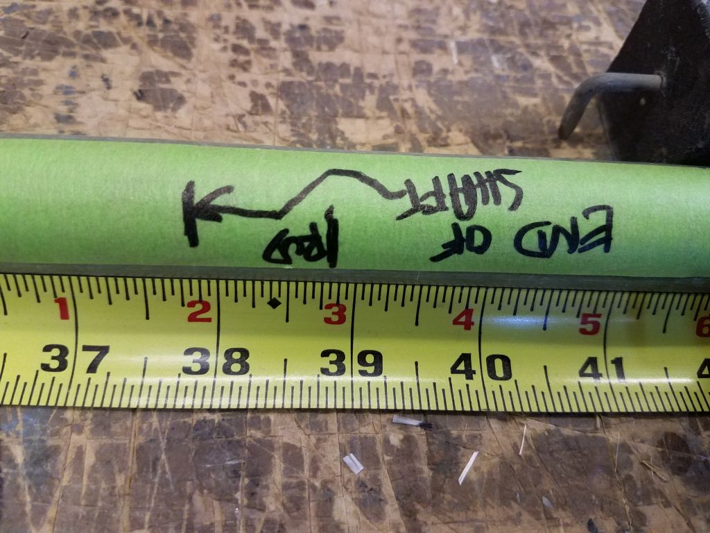
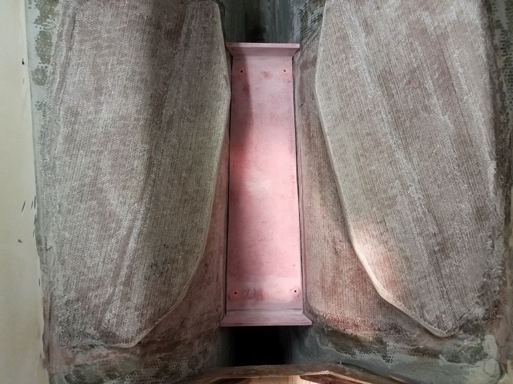
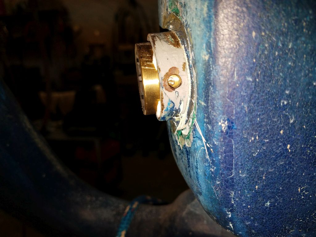
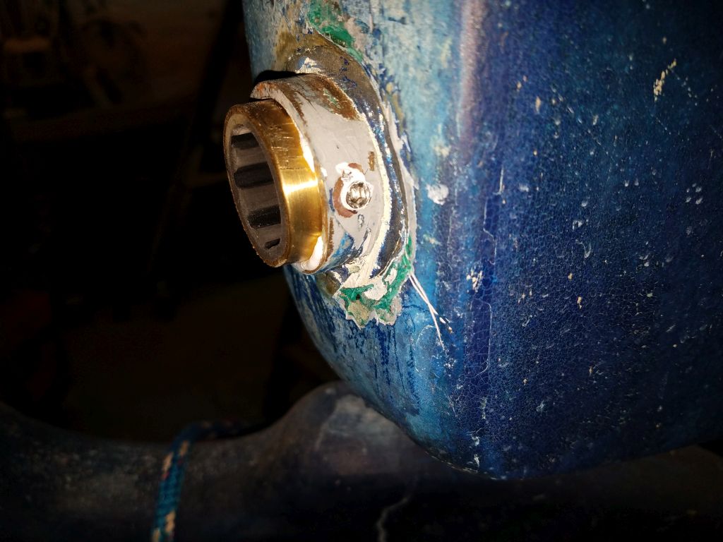
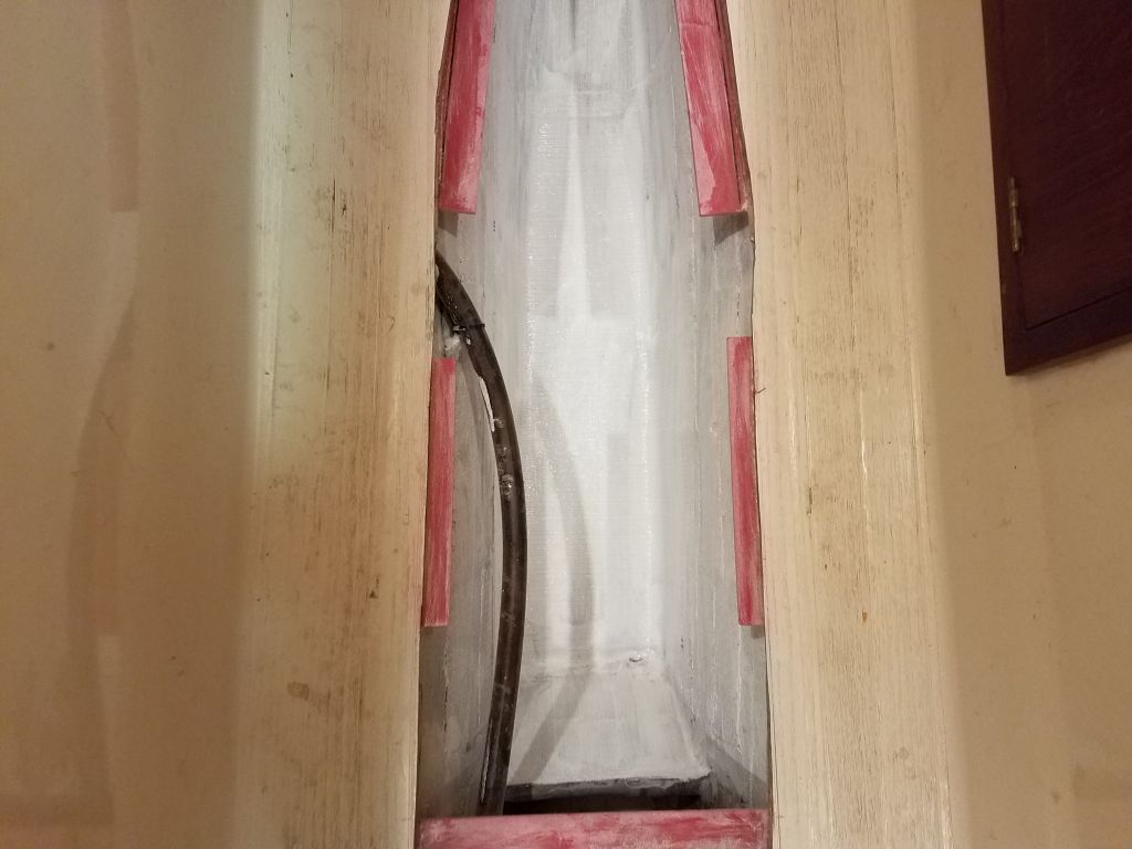
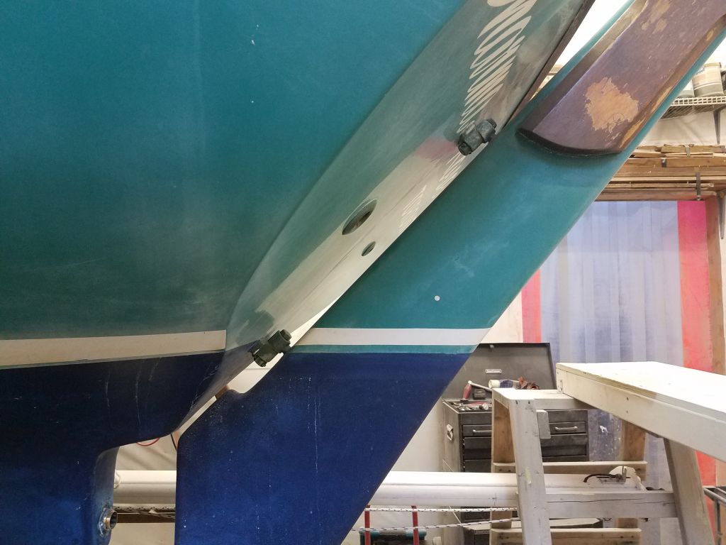
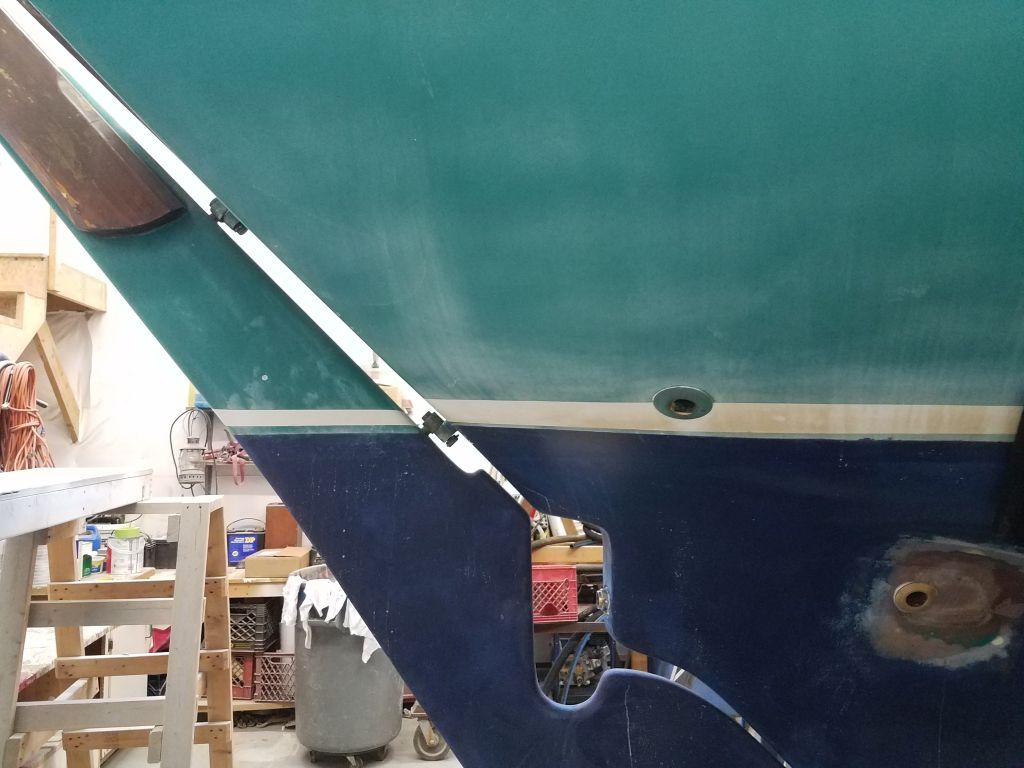
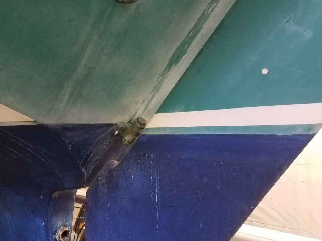
The instructions gave ample guidance on the final positioning of the vane (i.e. its final height) in relation to the boat’s load waterline.  On this boat, there was no obvious scum line visible from which to gauge the exact waterline, but I did have past knowledge of this boat model and knew about where I thought the waterline (at least for these purposes) should be.  I compared notes with the earlier installation, and found various easily comparable points on the boat to help confirm my instincts, and on this boat I ultimately chose the top of the bottom paint as the height from which to work, which corresponded well with floating pictures I had of a sistership.  Here, it corresponded with the top edge of the lower rudder gudgeon, and I extended that line aft onto the rudder for measurement and for some later steps.

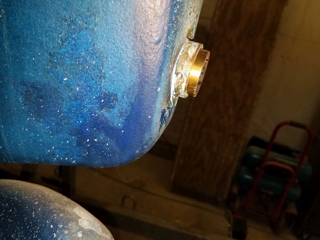
Note that the striping and bottom paint heights on the outboard rudder are actually quite a bit lower than those on the hull, a production inconsistency I’ve seen on three other Contessa 26s that have been in the shop.

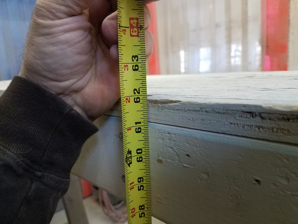
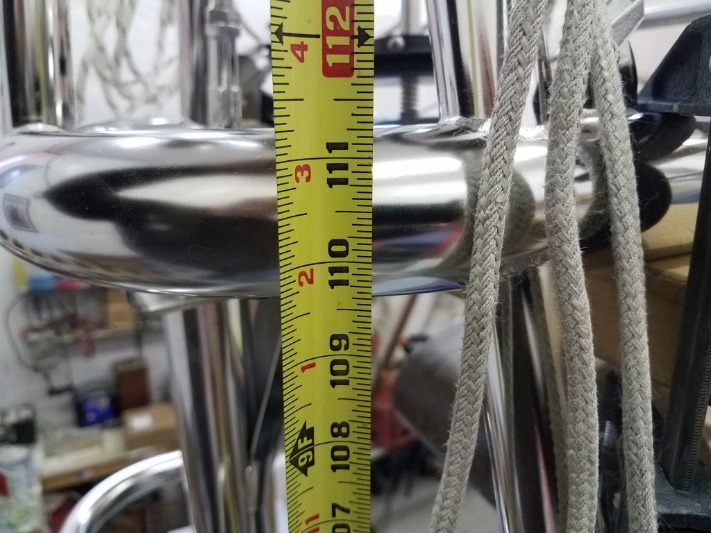
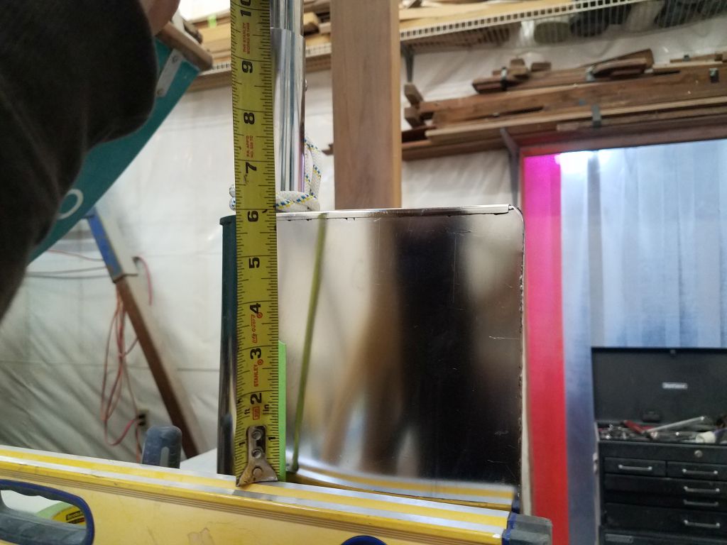
When all was said and done, I measured the new waterline height at 68-1/4″ from the floor.  Since the instructions indicated the main support tubes (the center thereof) on the frame should be 42″ above the waterline, this meant that the frame needed to be 110-1/4″ above the floor here.

Sometimes, past experiences can inaccurately color a fresh approach, and, in reviewing my notes from earlier, my mind somehow stuck on a note about a 15″ height difference between the main frame tubes and the curved after lower tube that protects the paddle arm from damage.  In hindsight, I don’t know why I ever noted this back then, because I didn’t actually build the frame in that instance using the lower tube either, but as I said it’d stuck in my head as important, so the net result was that I built my first basic support (four lengths of  2x4s screwed together with simple angle braces for strength) too short by 15″.  The calculations had made sense at the time, and all the math was right, but I’d erroneously subtracted the 15″ simply based on those earlier descriptions.  I knew as soon as I lifted the vane frame onto the support that I’d made an error, and it didn’t take long to figure out the simple cause.

Fortunately, this was a simple fix, and before long I’d rebuilt the frame with longer side legs to bring the height up where I needed it (which was just one inch shy of the final desired height; the last inch came from the half diameter of the 2″ main support tube).

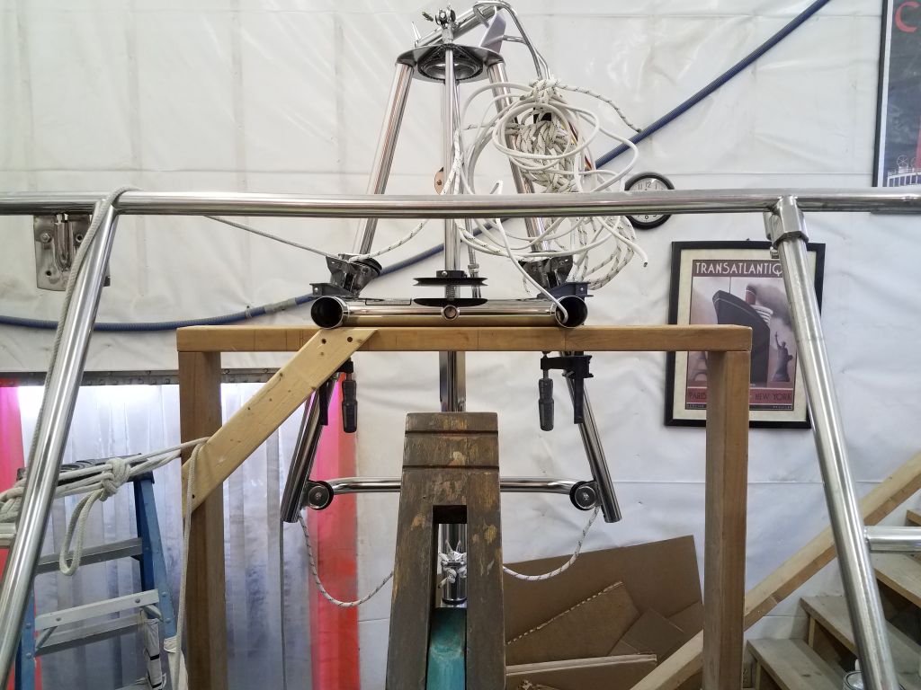
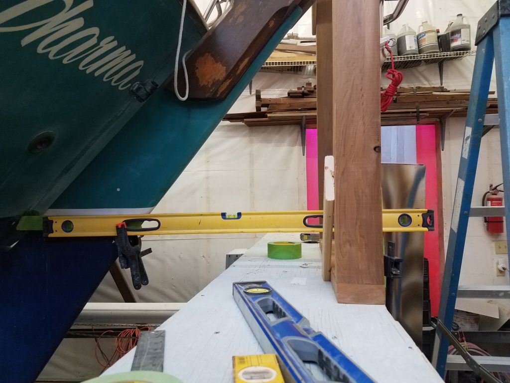
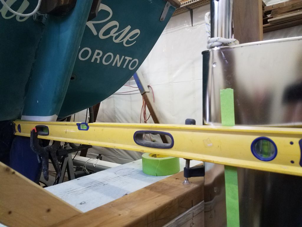
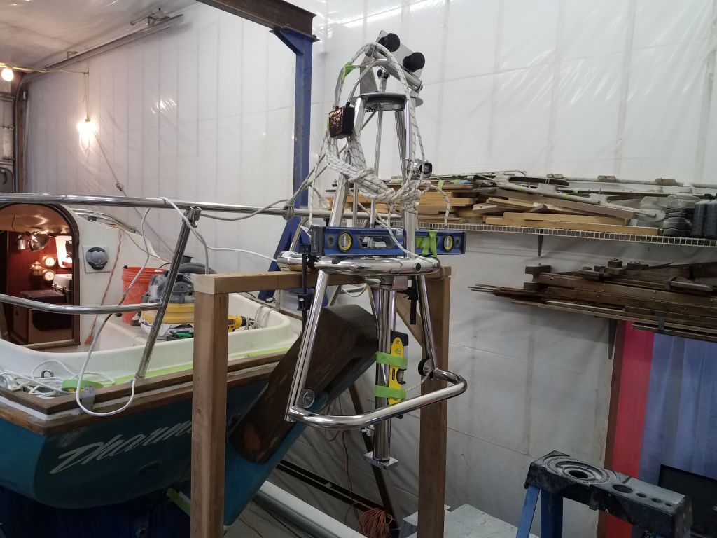
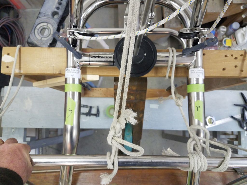
Now, with the frame set atop my framework and centered according to the slot in the rudder cheeks ahead, I measured the height to the center of the main tube at 110-1/4″ from the floor, right where it needed to be.

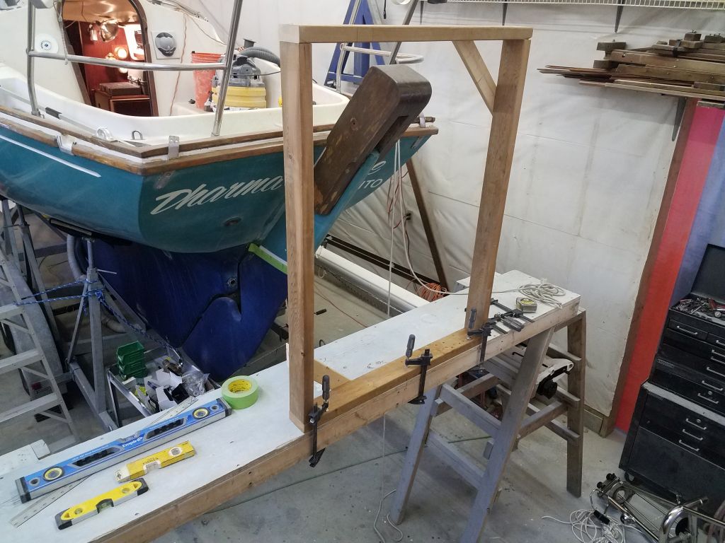
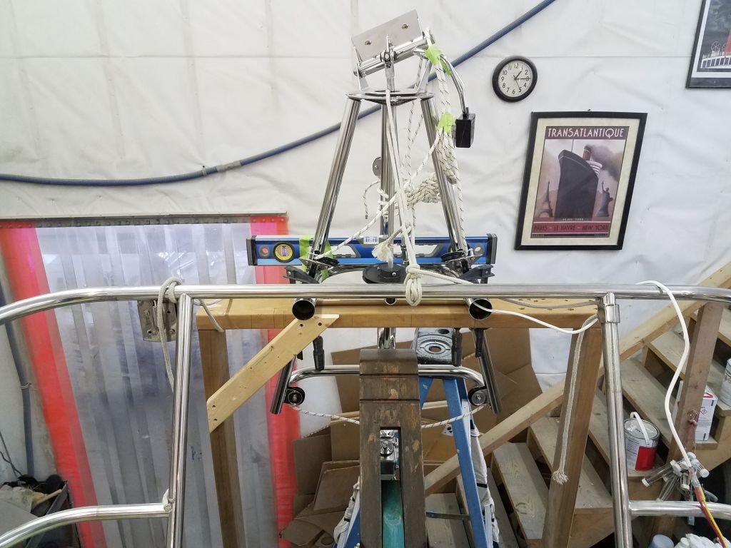
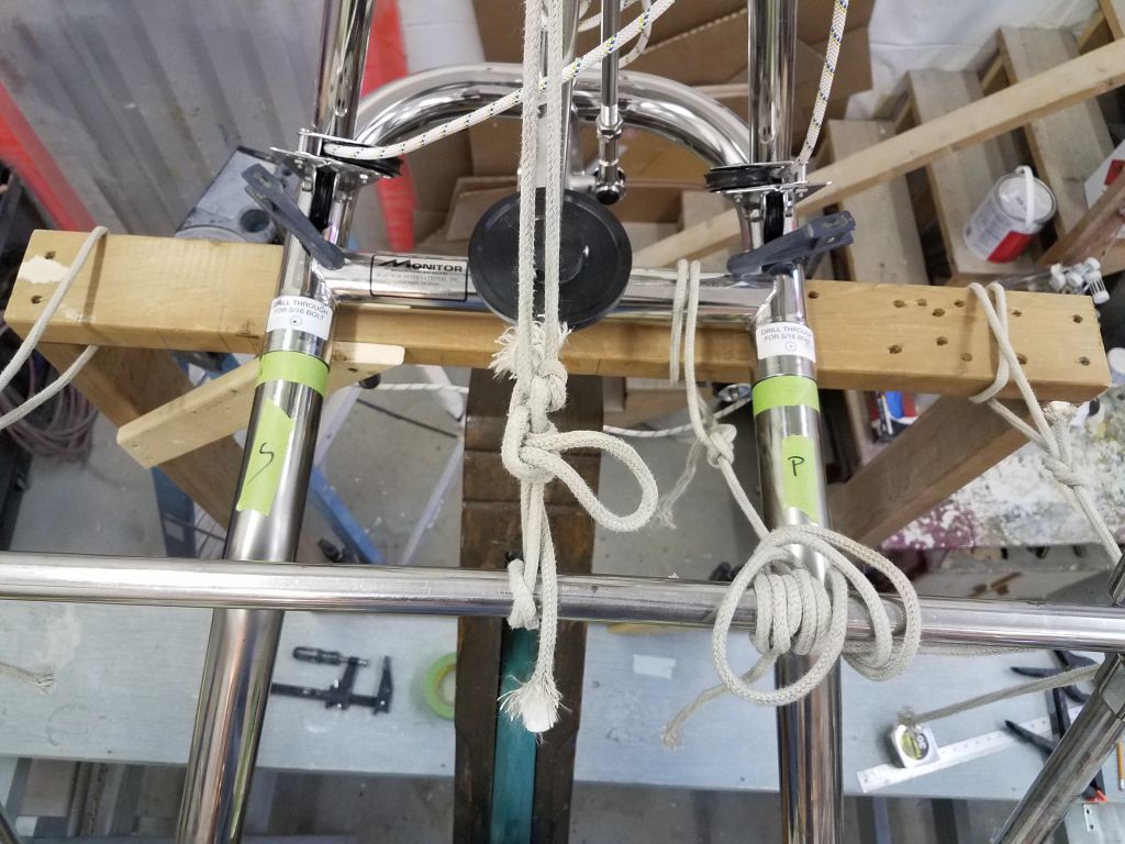
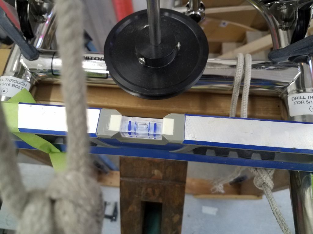
With the vane clamped in place and some safety lines, I adjusted the support and staging plank as necessary to bring the vane where I wanted it in relation to the hull (basically as close as practicable to the top of the rudder cheeks in this case, without fear of interference now or ever).  On the framework, the frame of the windvane was level from side to side.

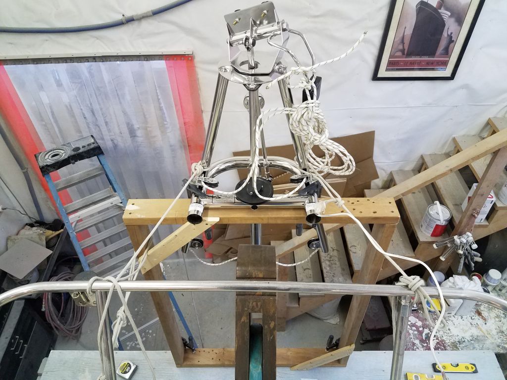
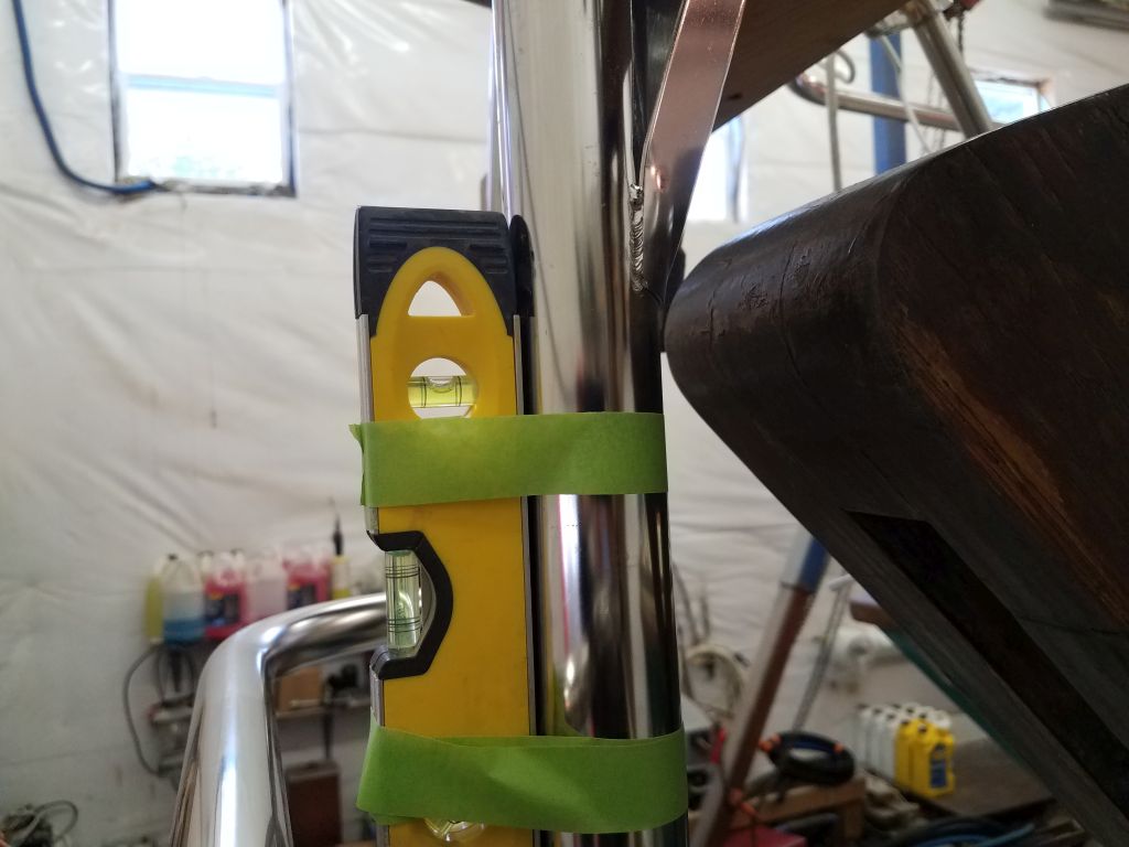
To double-check the height of the frame where I had it, I temporarily installed the vane paddle, and with a line adjusted the vane till it was vertical (i.e. level fore and aft).  Then, I extended the waterline mark from the rudder aft onto the paddle itself, and checked how far the paddle extended above this line:  six inches, just as the directions indicated.

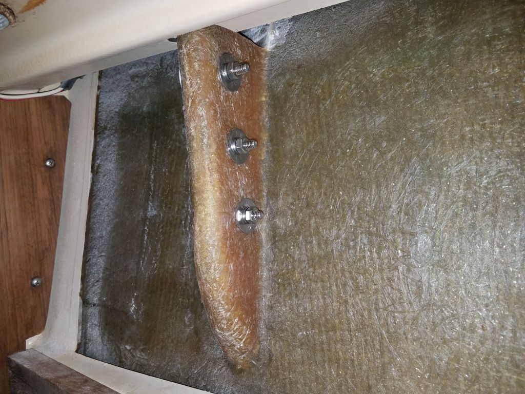
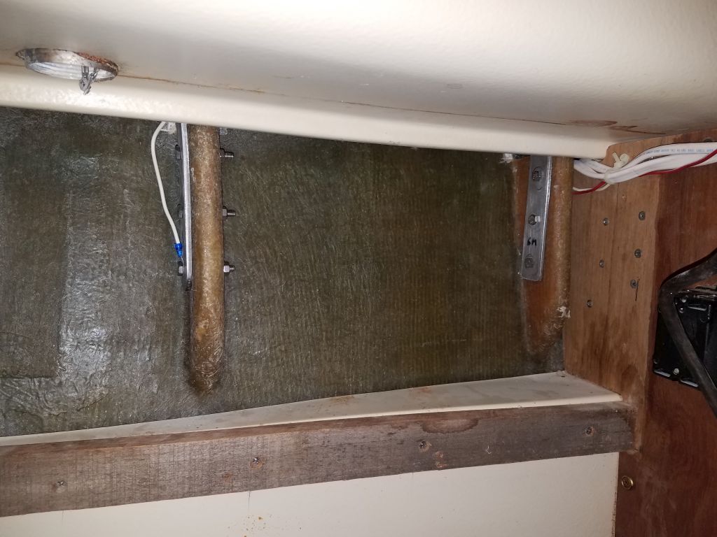
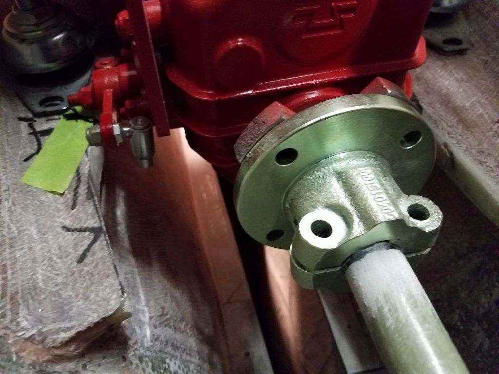
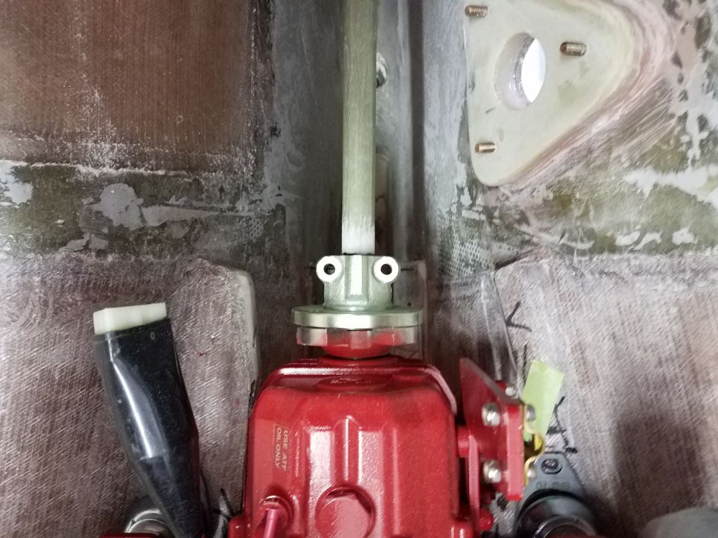
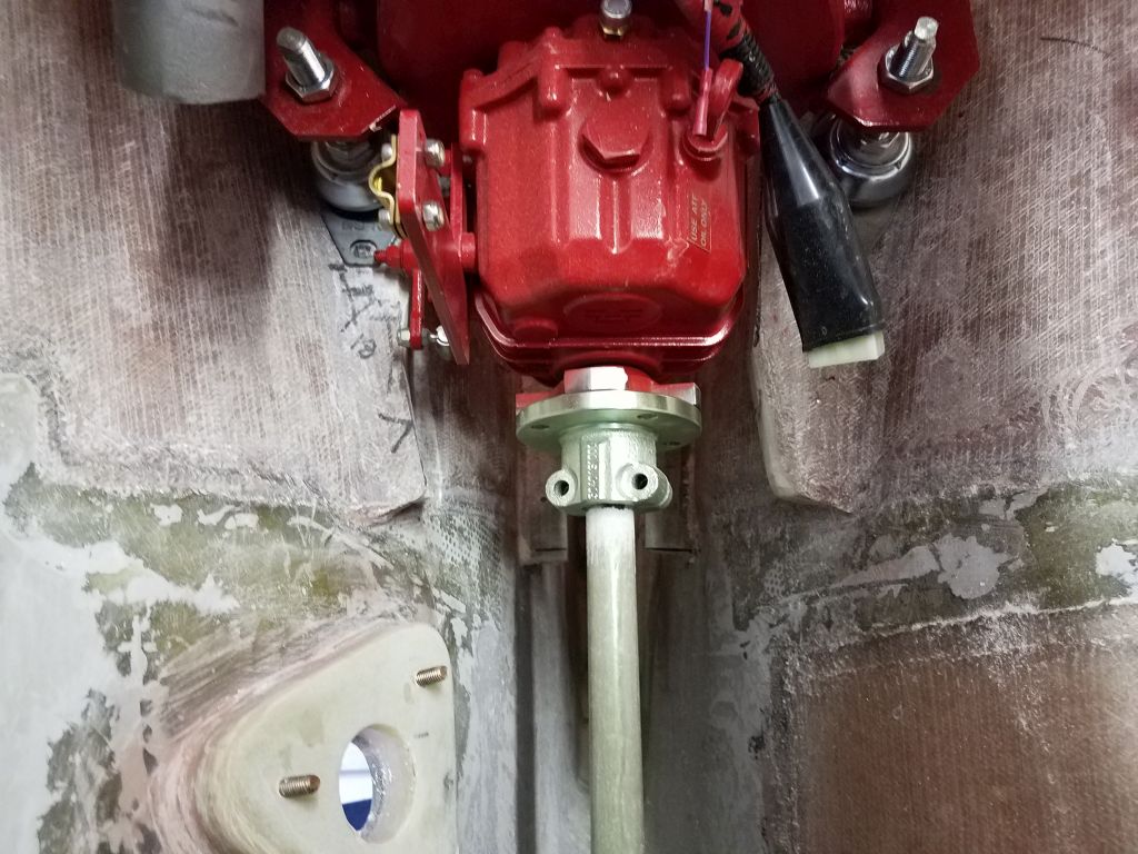
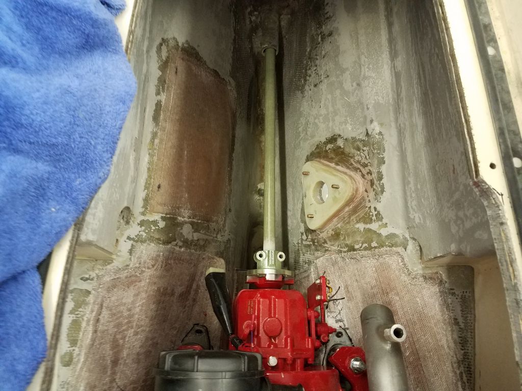
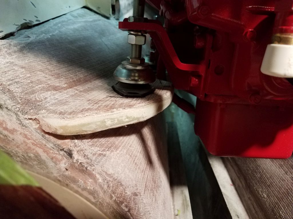
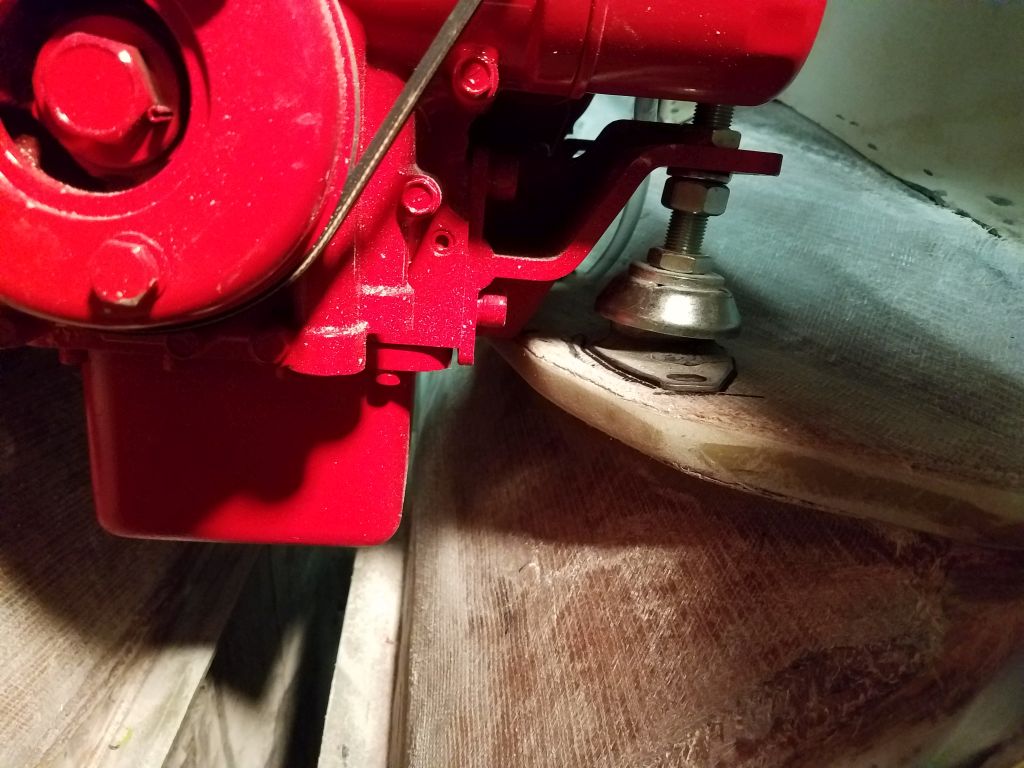
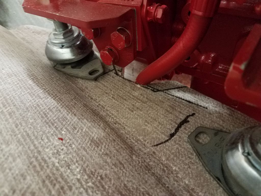
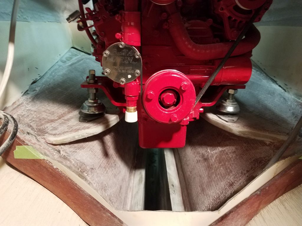
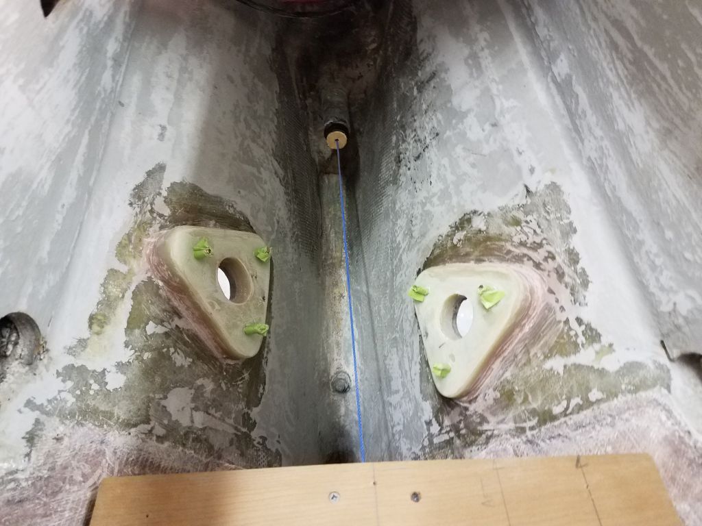
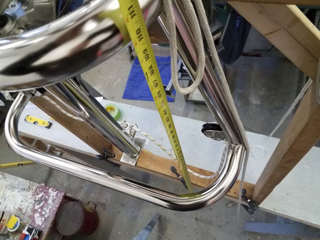
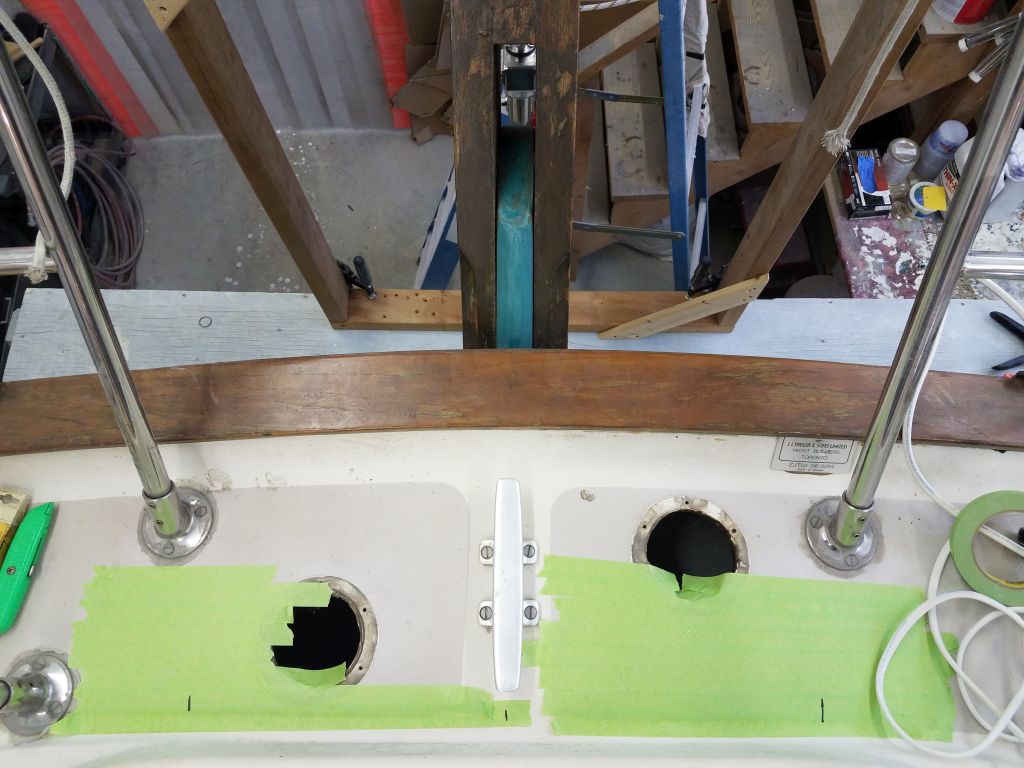
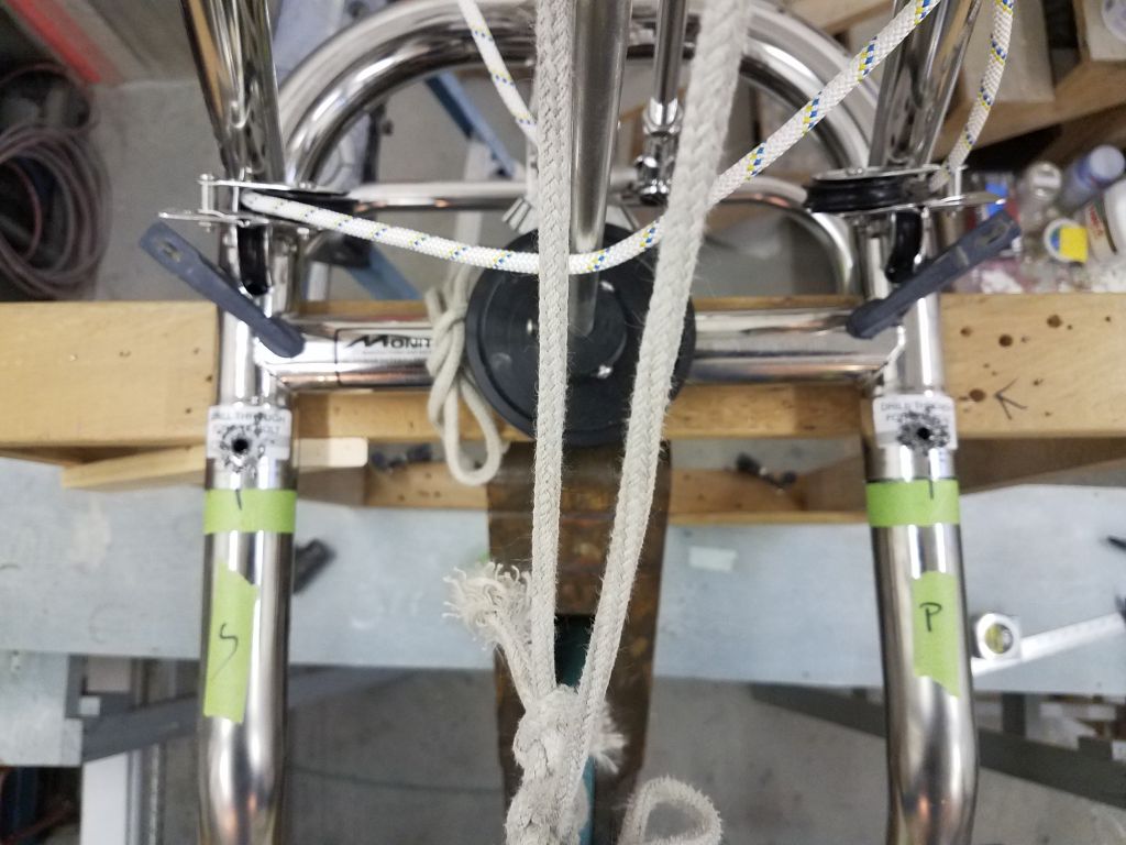
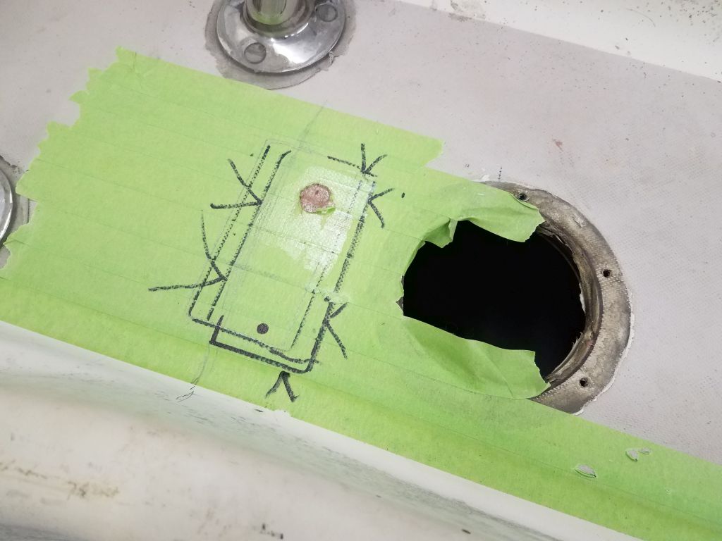
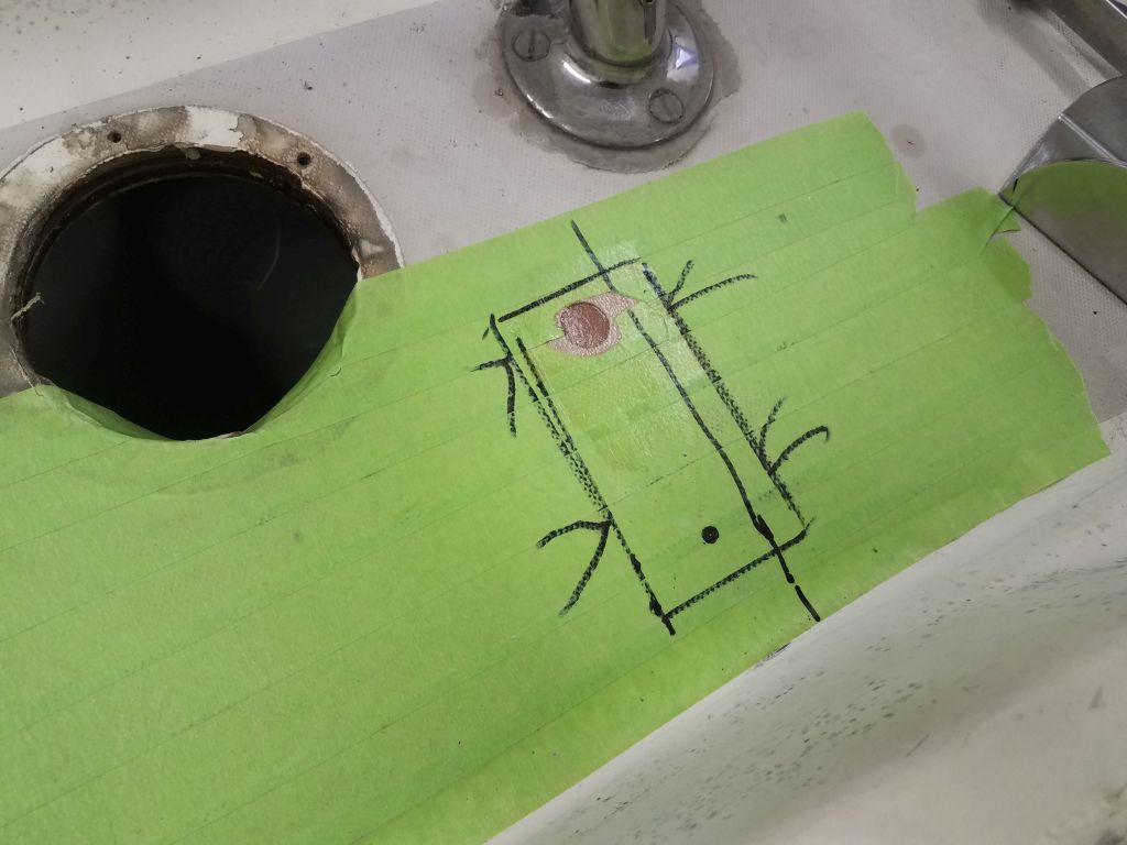
Now, with the vane properly positioned in all aspects, I could begin the actual support tube installation.  On this boat, this meant a pair of 2″ diameter double-curved tubes that extended from the main frame sockets down to the aft deck, splaying out to the sides in the process.  The directions suggested the centers of the tubes should be about 25″ apart on the deck, so after masking over the decks on both sides I made a couple marks just for general reference, since the tubes and brackets themselves would ultimately dictate the final positions.

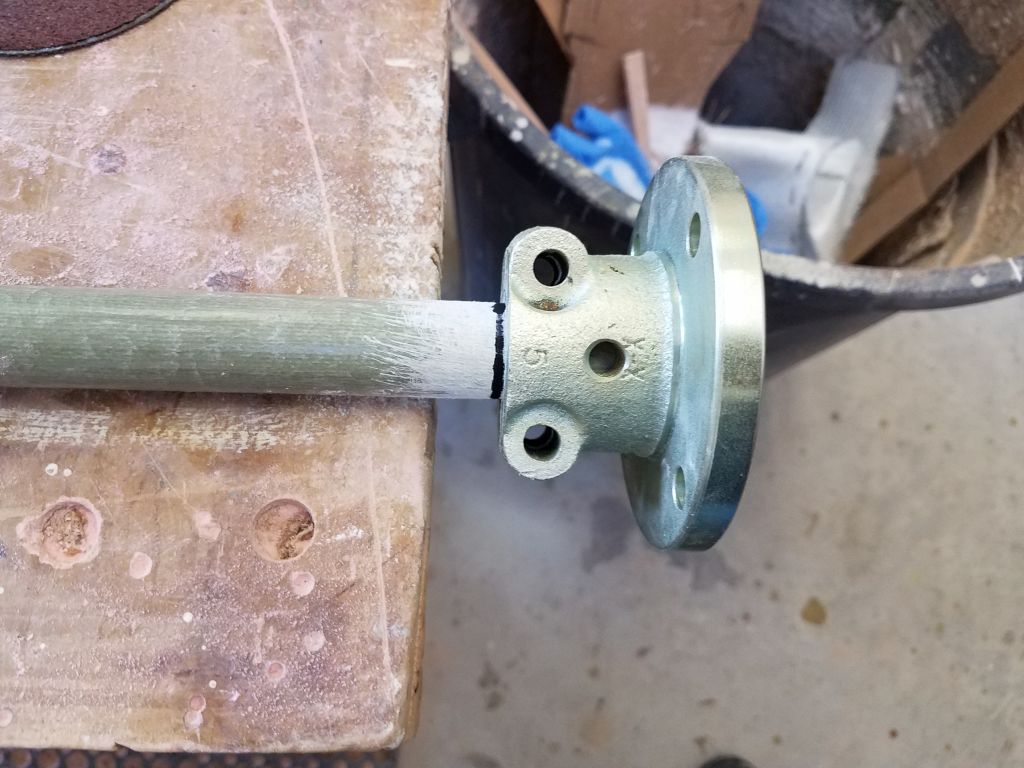
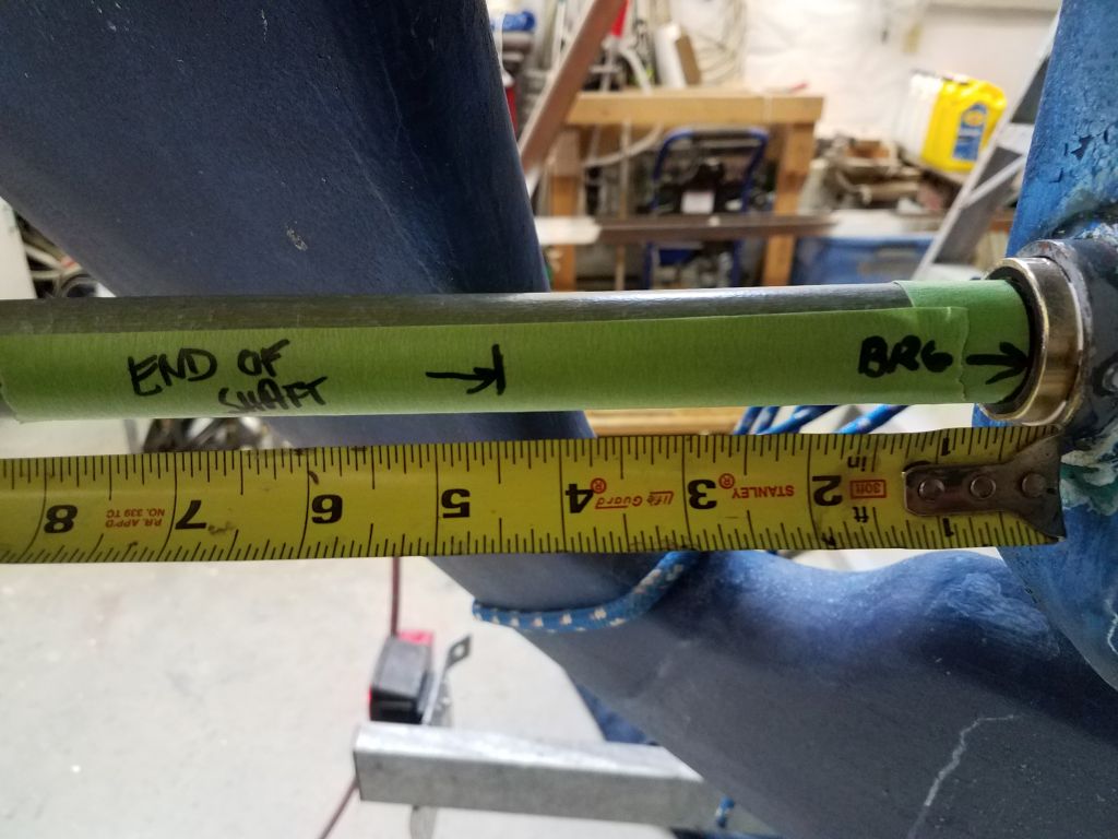
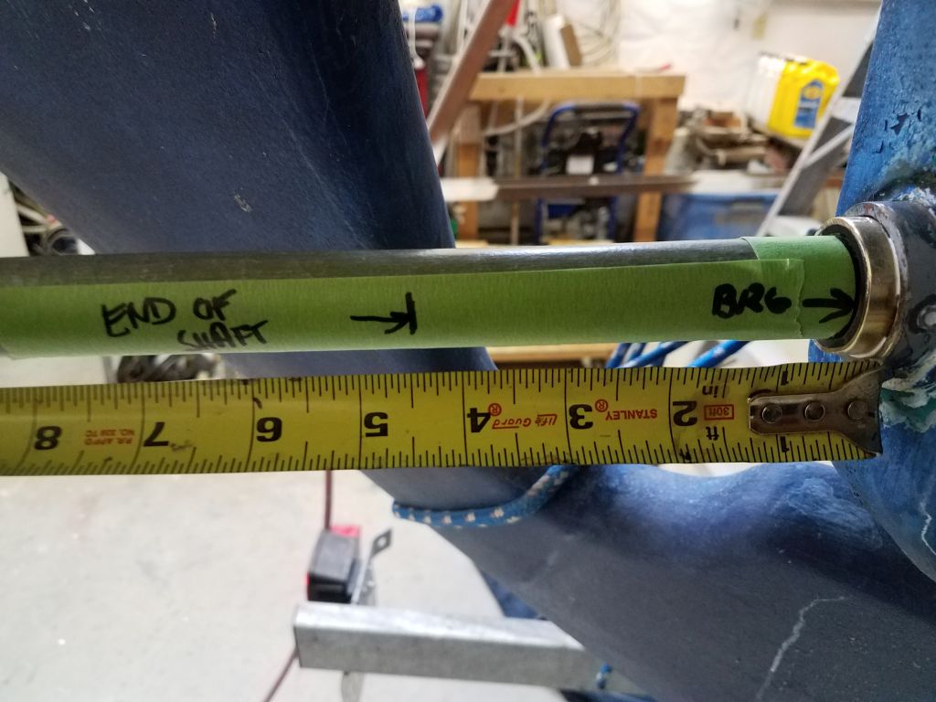
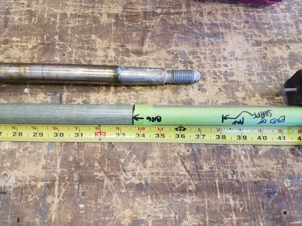
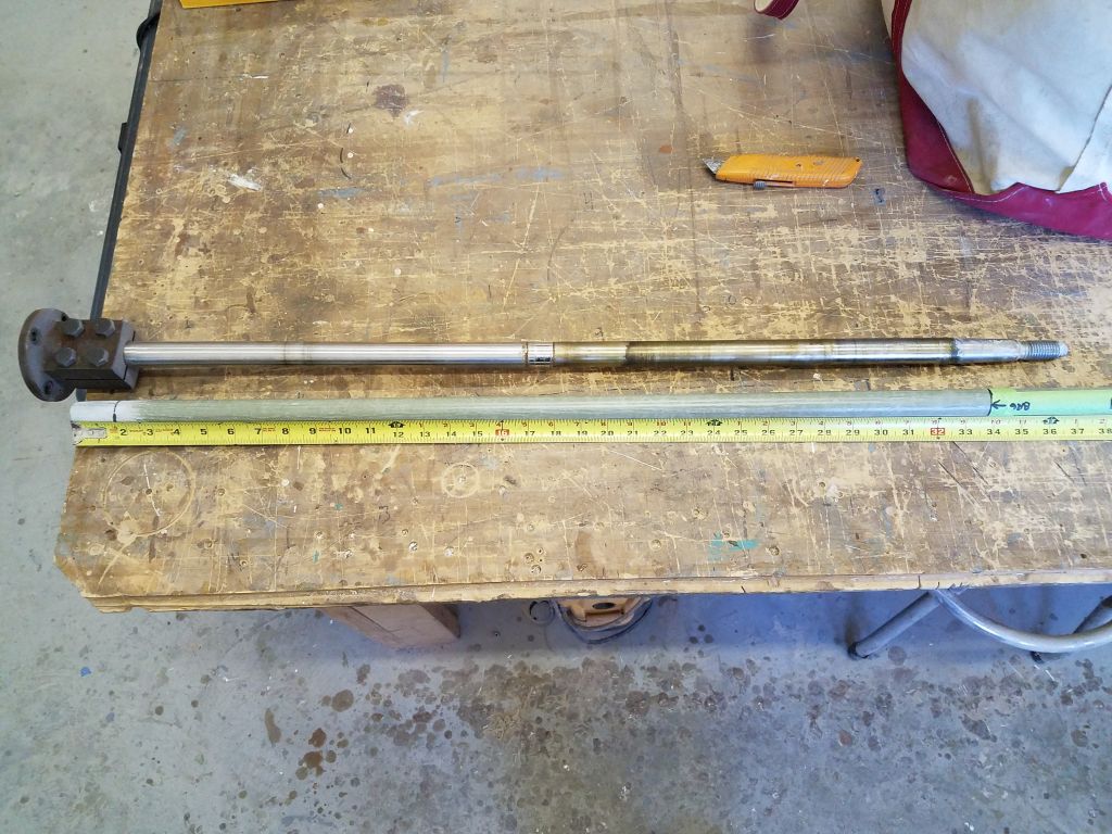
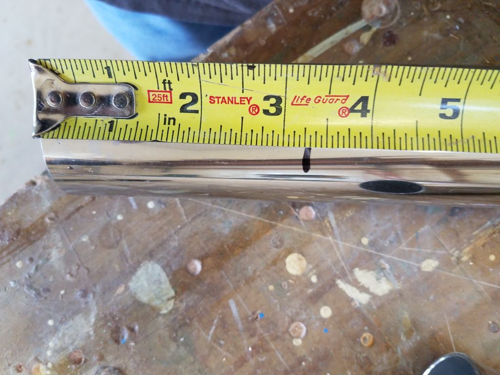
Using one of the tubes, I held it against the main frame to see how the as-provided length worked out, and made a mark where I could cut some of the excess tube length given the vane frame’s position a couple inches aft of the top of the rudder.

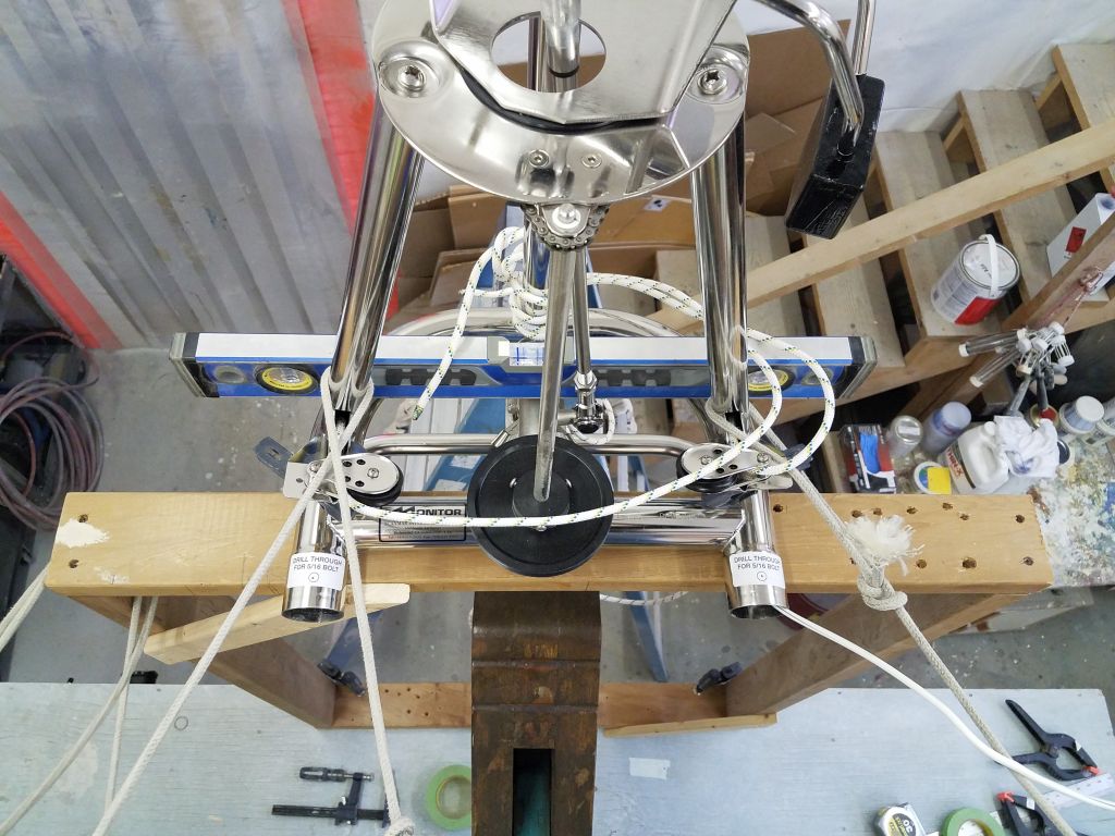
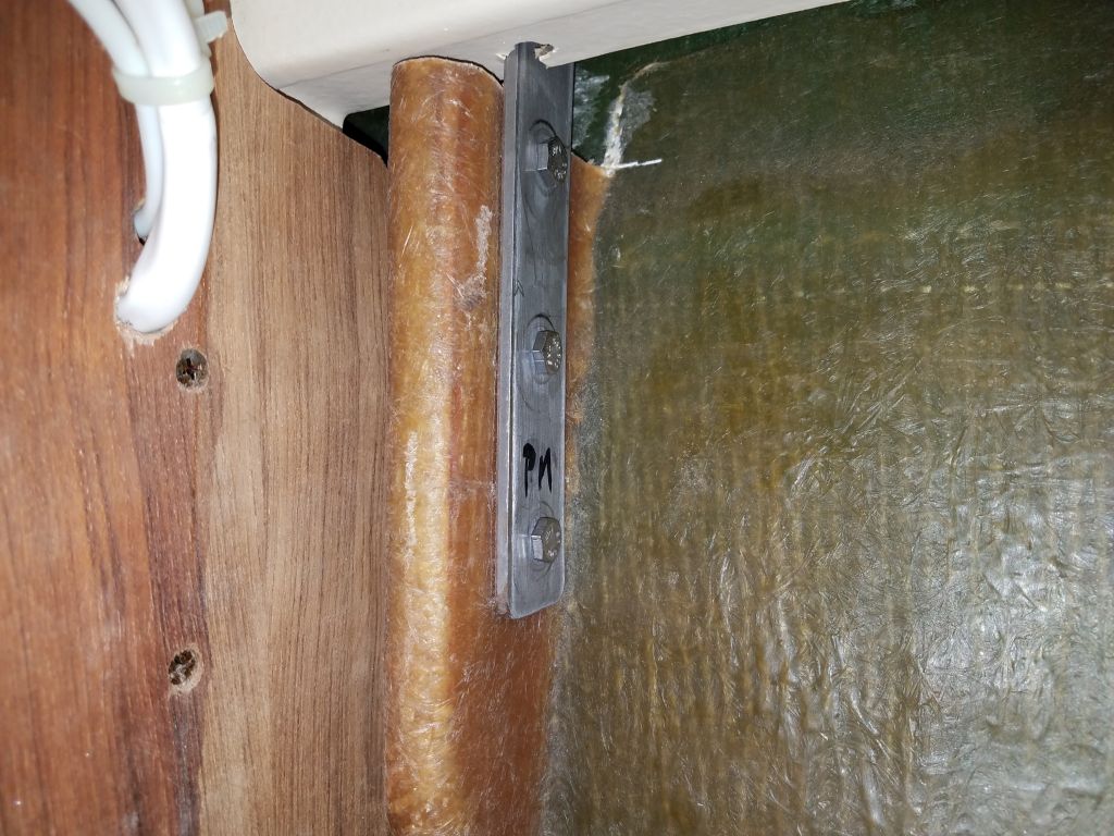
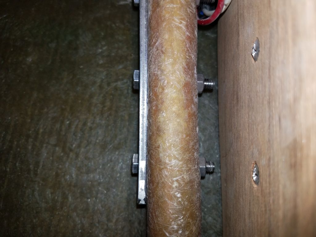
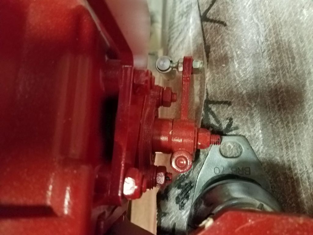
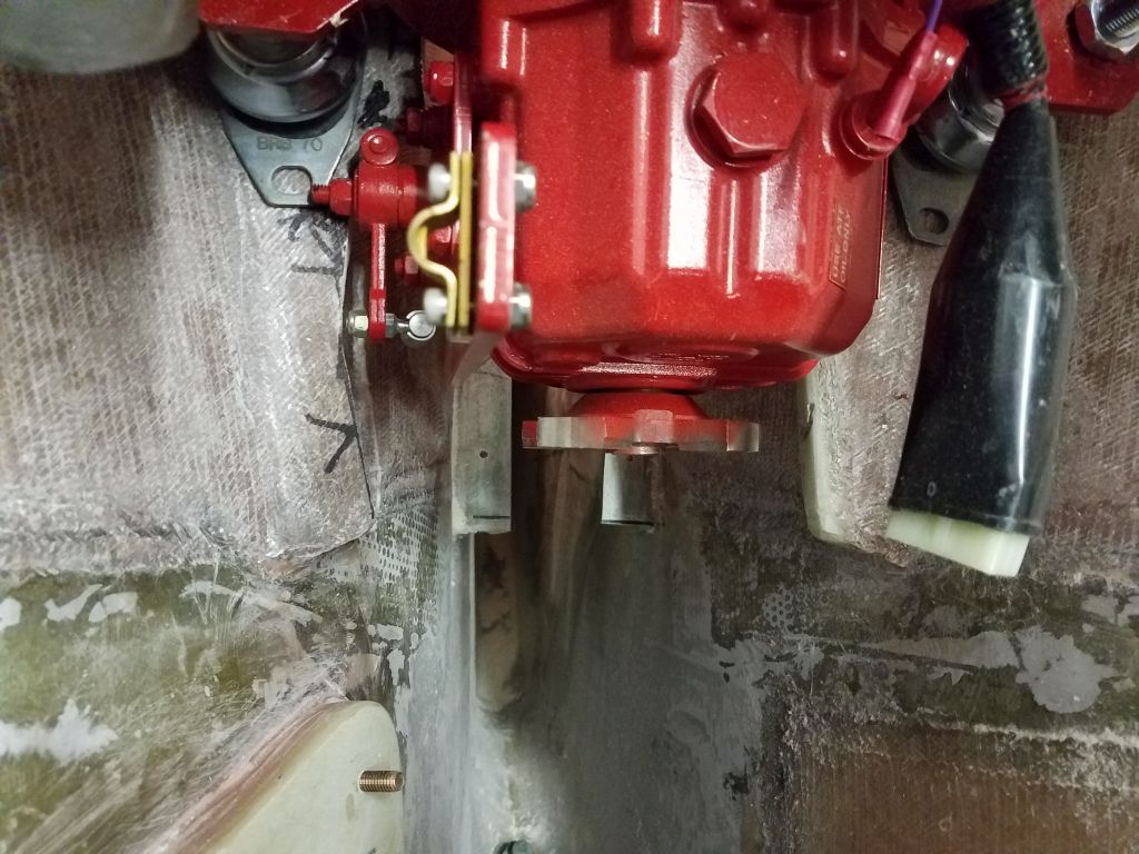
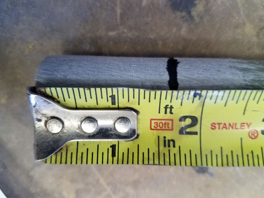
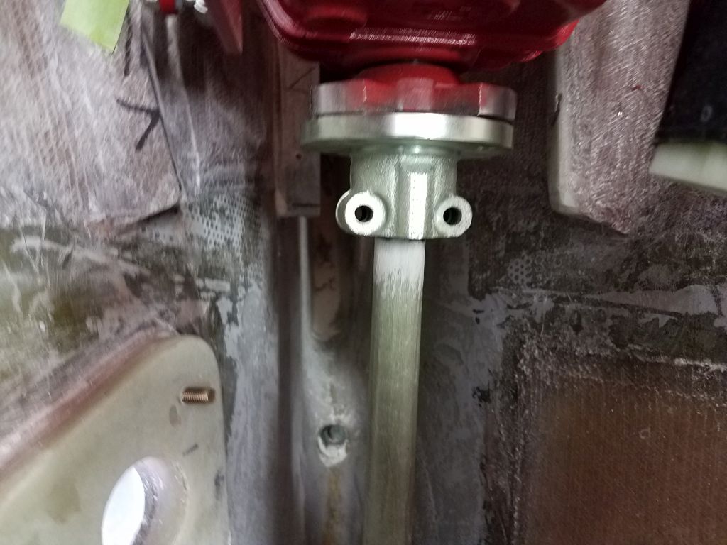
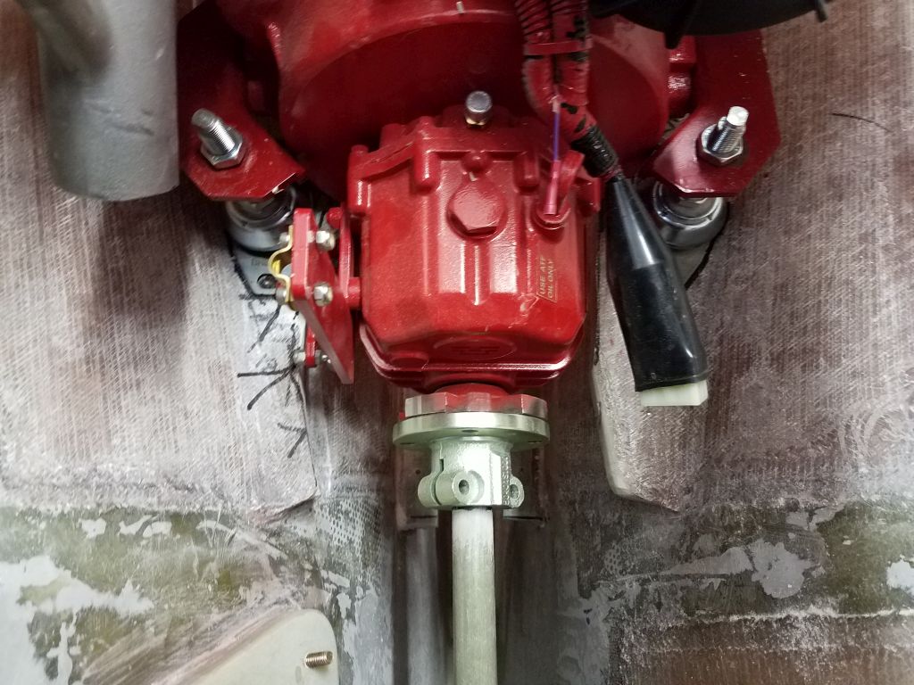
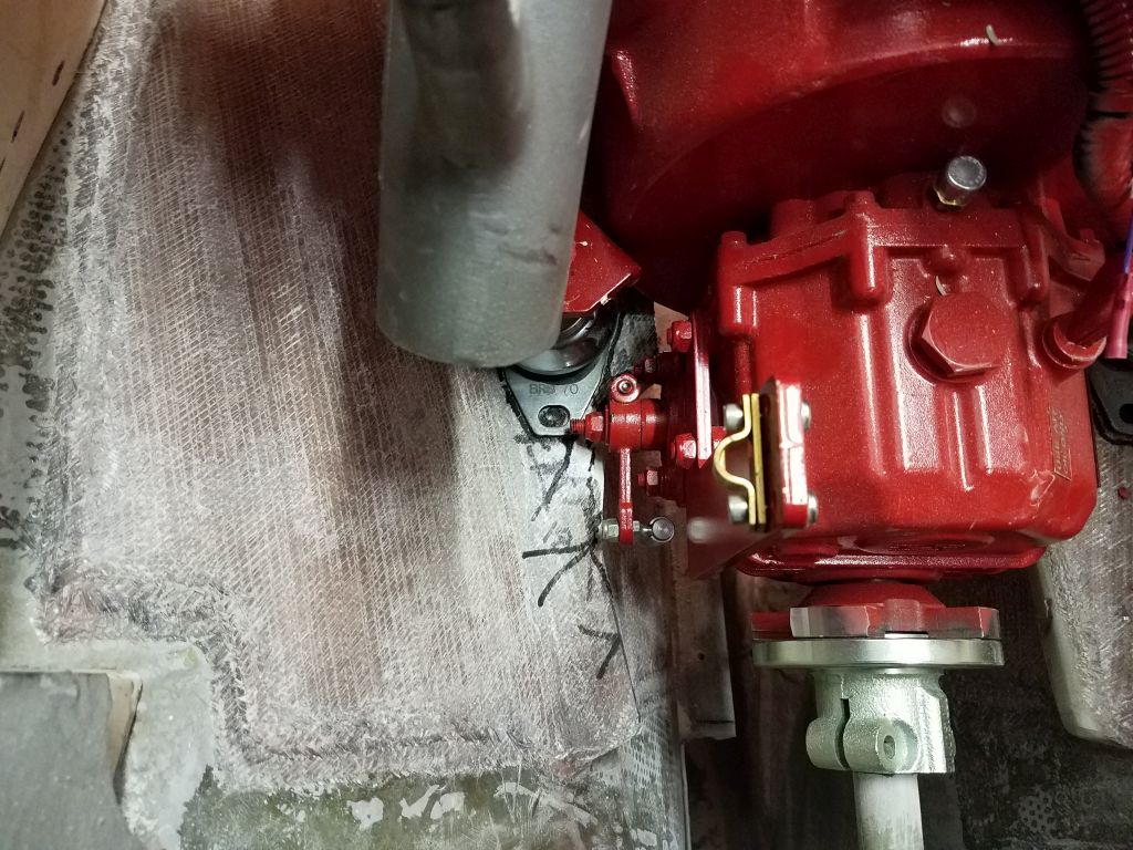
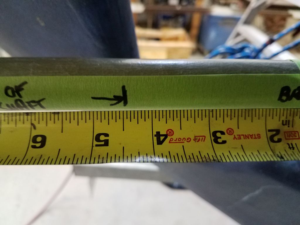
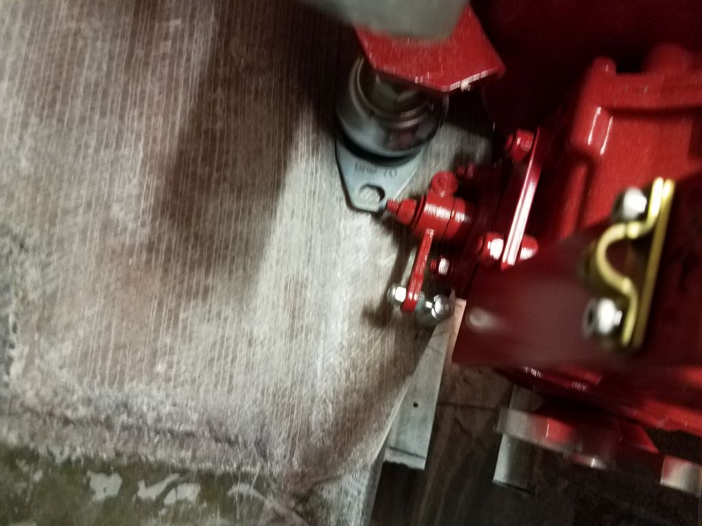
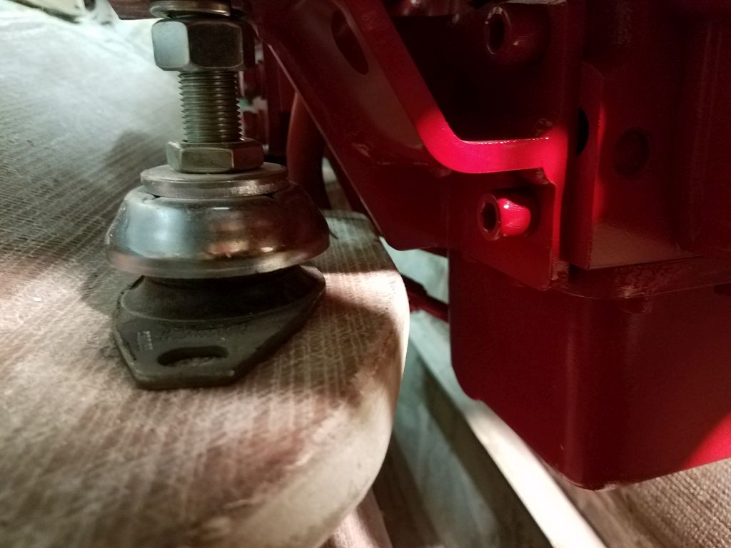
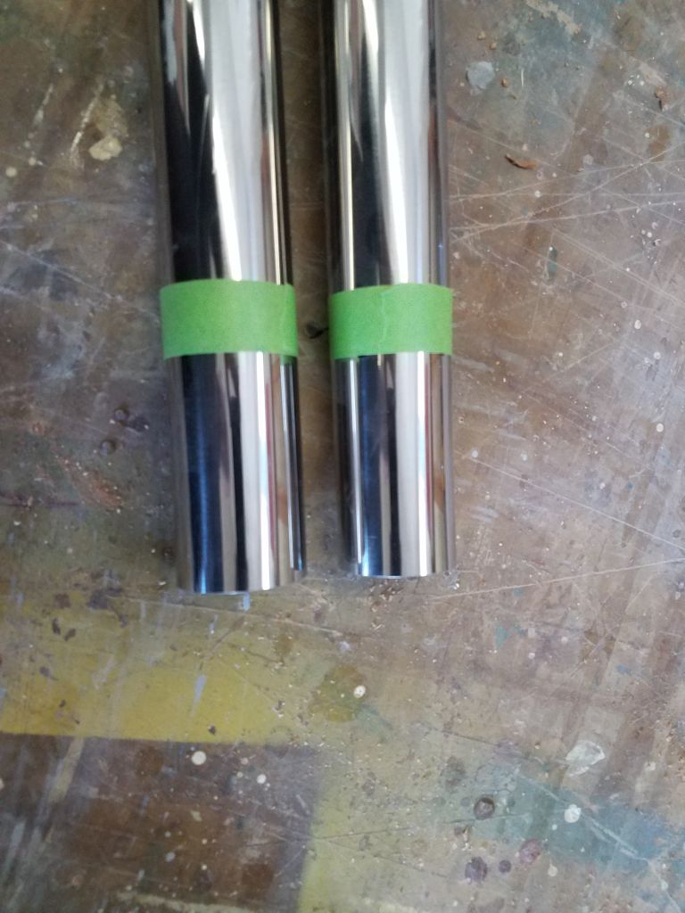
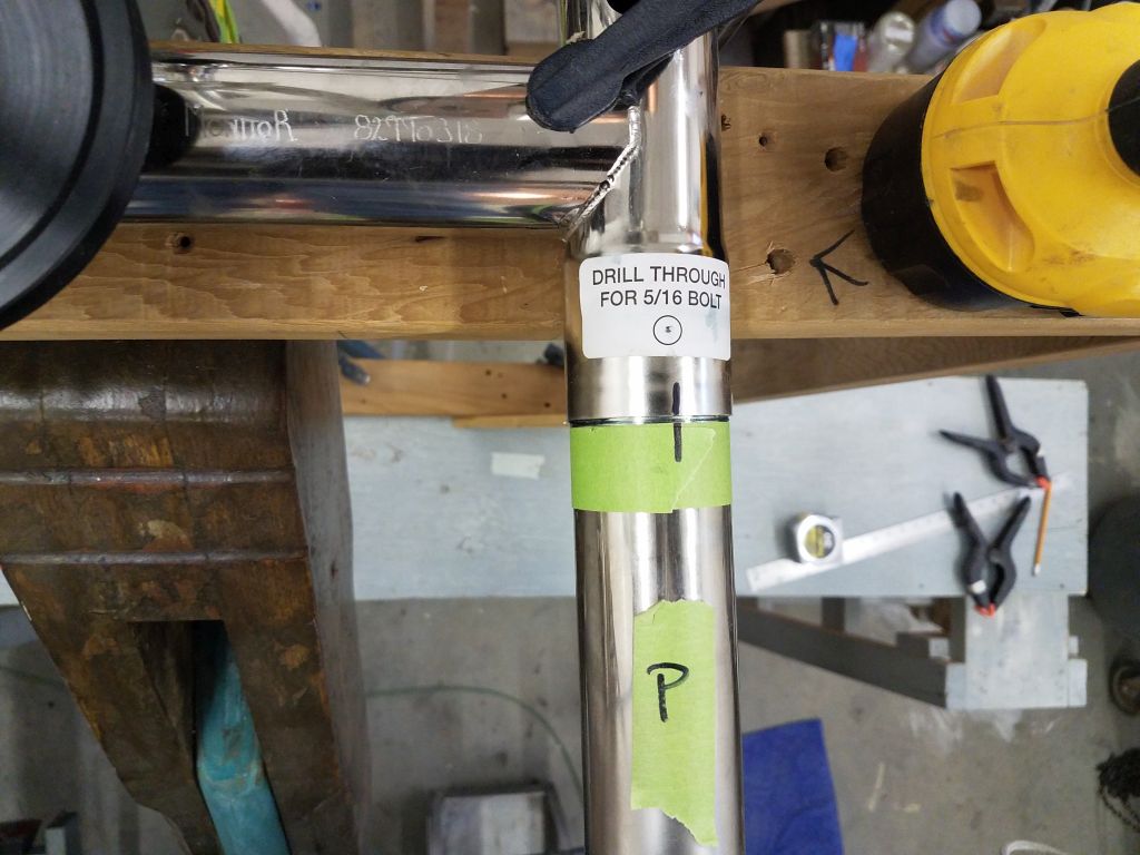
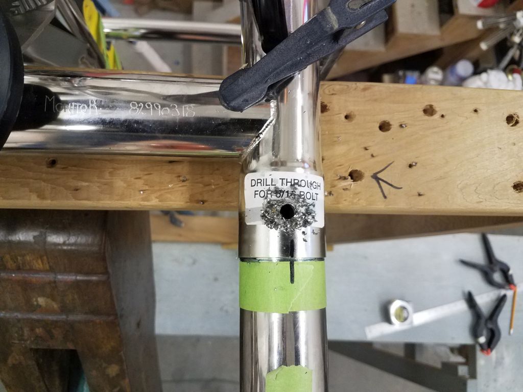
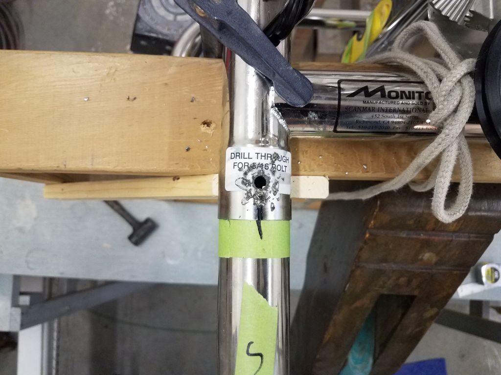
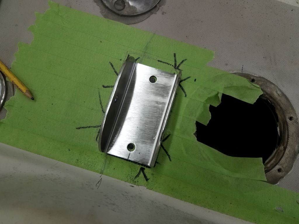
Down on the bench, I cut off the excess length (about 3-5/16″ here), and test-fit the tube on the starboard side before cutting its counterpart to port.  I found the tubes’ fit within the frame sockets to be extremely tight and dry, making installation and removal (which is required several times through this early process) quite a challenge.  Some waterproof grease on the tubes and sockets helped, but it was onerous.  Eventually, keeping the frame level throughout the process, I determined the mounting positions for the brackets that would hold the tubes to the deck, and marked them accordingly on the masking tape.  With each tube held in place in the bracket, I marked through the holes on the sides of the brackets for the holes I’d need to drill through these tubes to secure them there in the final installation.  At the socket ends, I used tape to mark the tubes where they were fully inserted in the sockets for future reference.

This essentially simple process, given the care I took in measuring and checking, the time consumption of the tight tubes in the sockets, and other considerations (including a broken top support on my wooden frame, the victim of the excessive force required to twist and push the tubes in and out of the sockets; I had to remove the vane and rebuild the top of my frame before continuing), took quite some time, but these initial two tubes were the most critical in the installation.  At length, however, and as the afternoon drew to a close, I reached a point where I could remove the tubes a final time and prepare ahead for a more streamlined day of installation tomorrow.

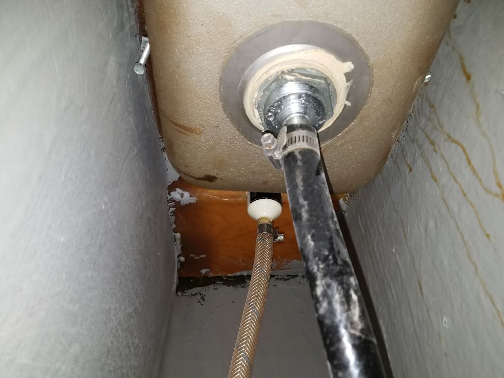
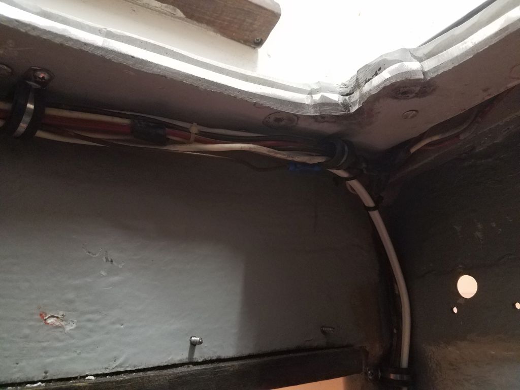
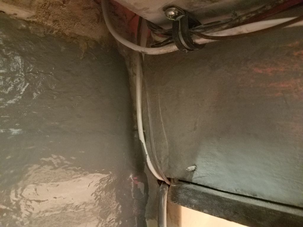
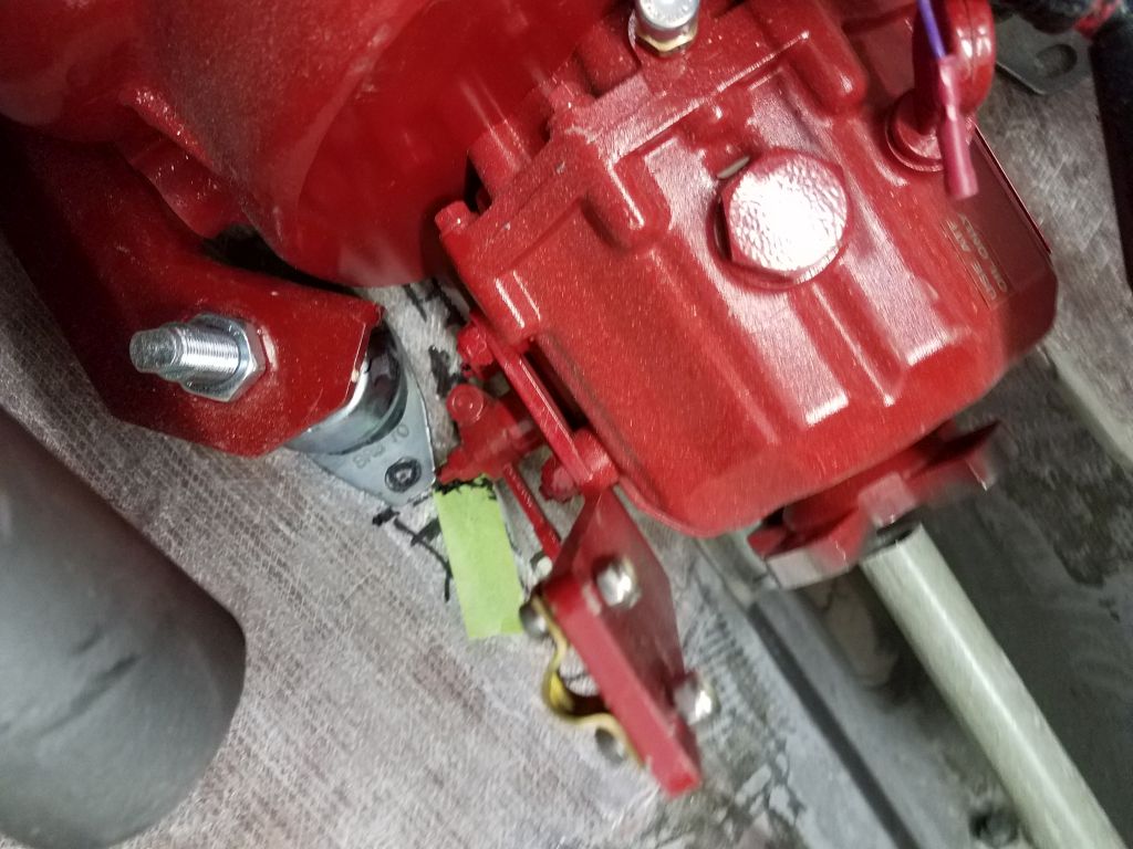
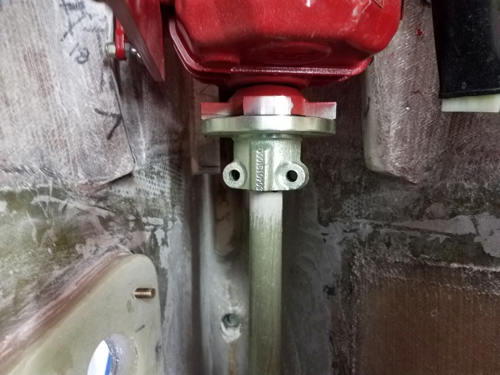
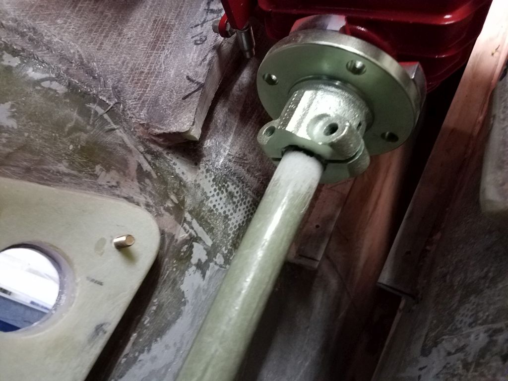
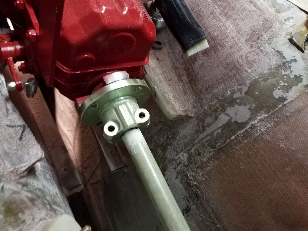
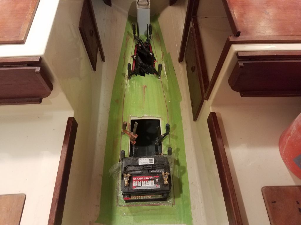
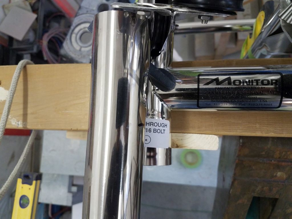
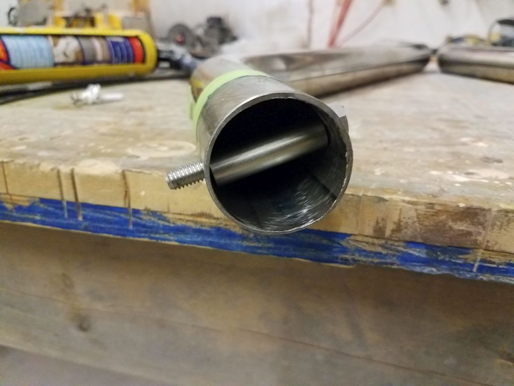
First, though, after ensuring for the 97th time that the tubes and frame and brackets were all as I wanted/needed them to be, I went ahead and drilled through the Monitor frame sockets and main tubes at the marks indicated on the frame.  I chose to drill these bolt holes now (they’d eventually secure the tubes to the frame) because there were internal compression supports that were required, and I didn’t want to remove or reinstall these tubes any more times than absolutely necessary (i.e. one more time).  So with fresh, sharp drill bits, of which I’d laid in an ample supply, a new drill battery, and some cutting oil, I drilled the 5/16″ holes through socket and tube (taking care on the port side to avoid the lighting wire within).

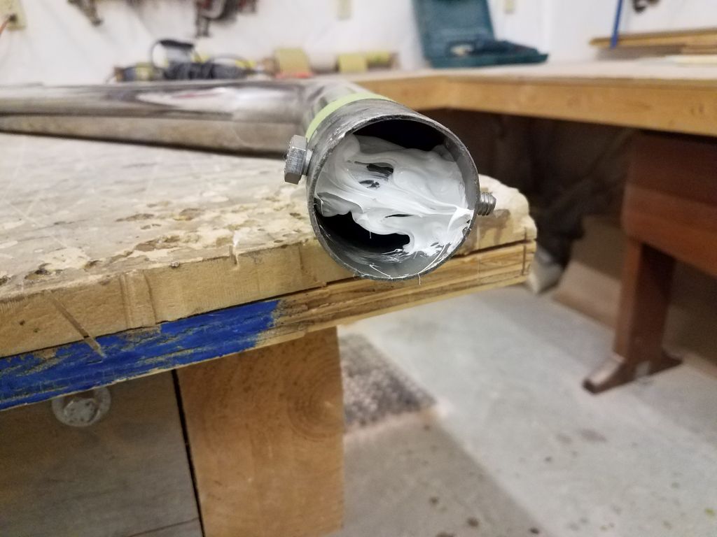
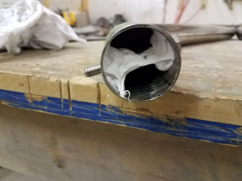
Now I removed the tubes, and down on the bench I fit in the supplied compression sleeves, holding them in the proper position with the bolts themselves, and used sealant to secure the sleeves inside the tube, just to hold them in place and prevent them from falling out during installation or at some point in the future should the tubes ever be removed.

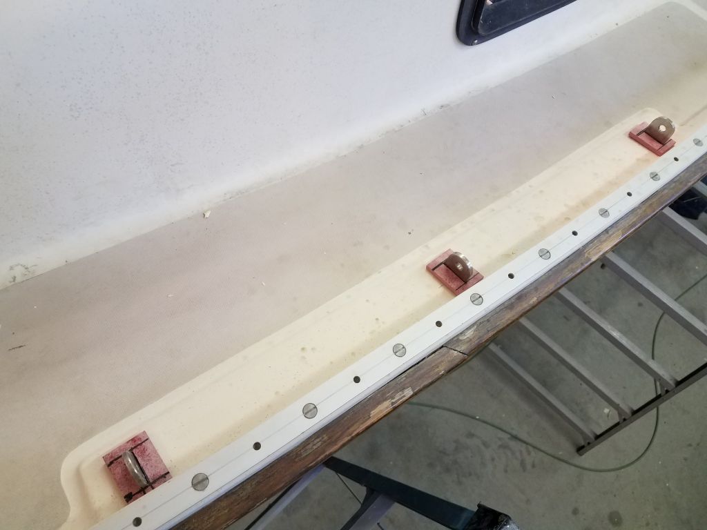
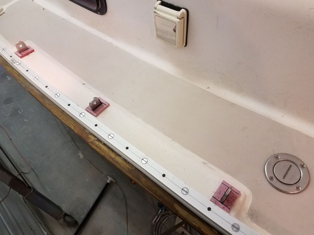
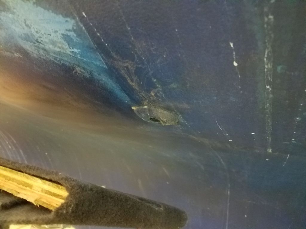
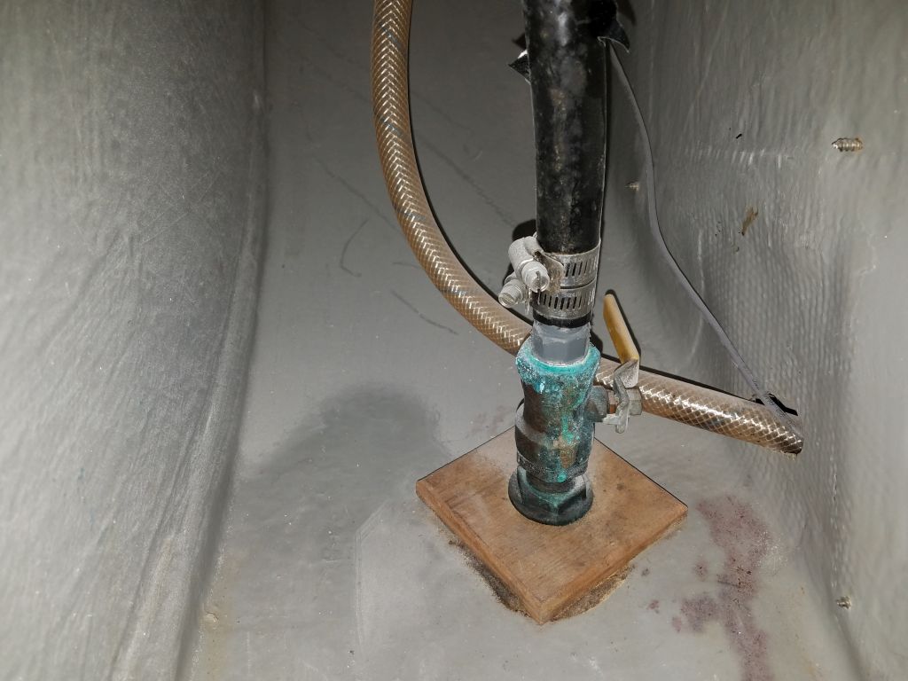
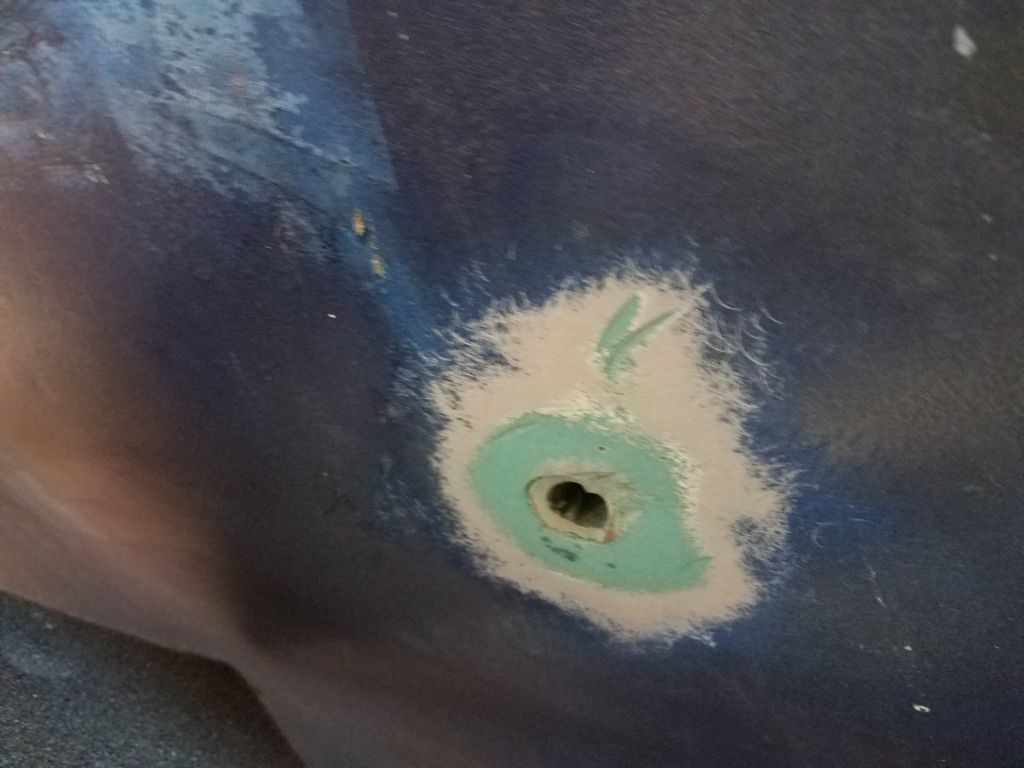
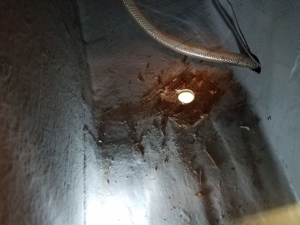
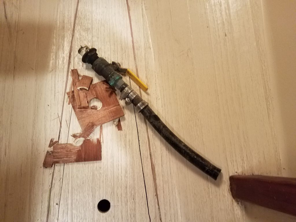
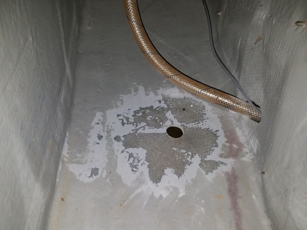
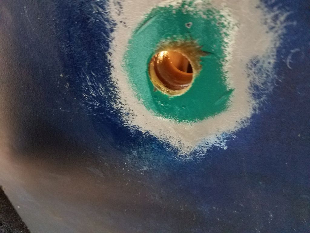
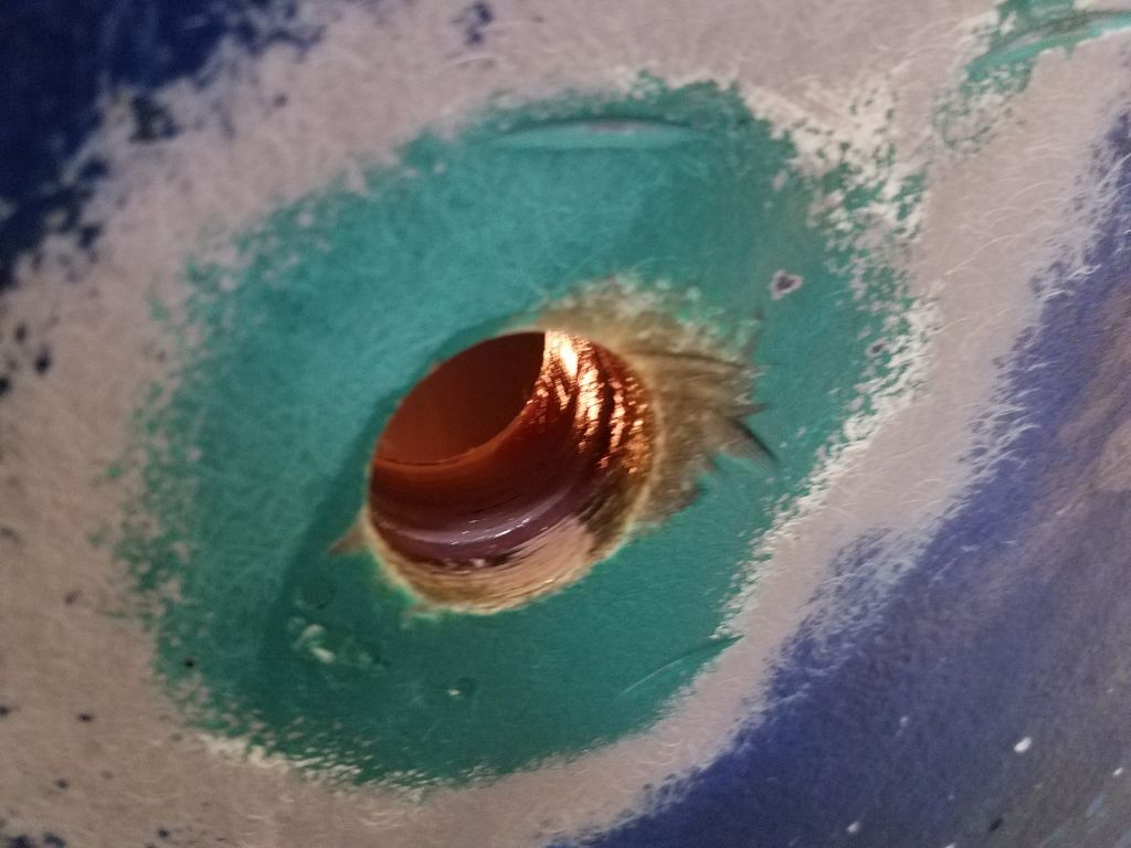
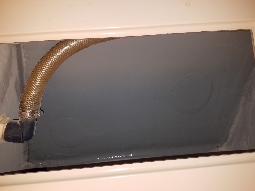
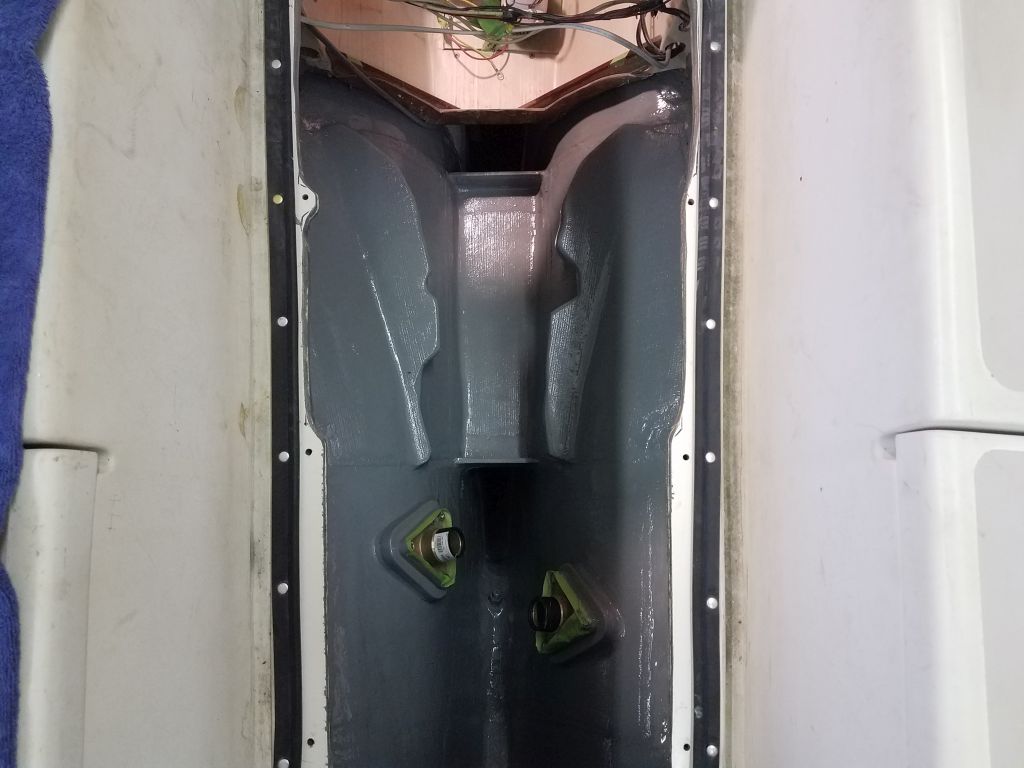
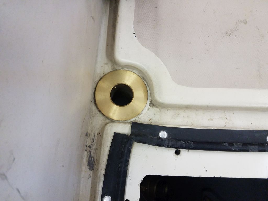
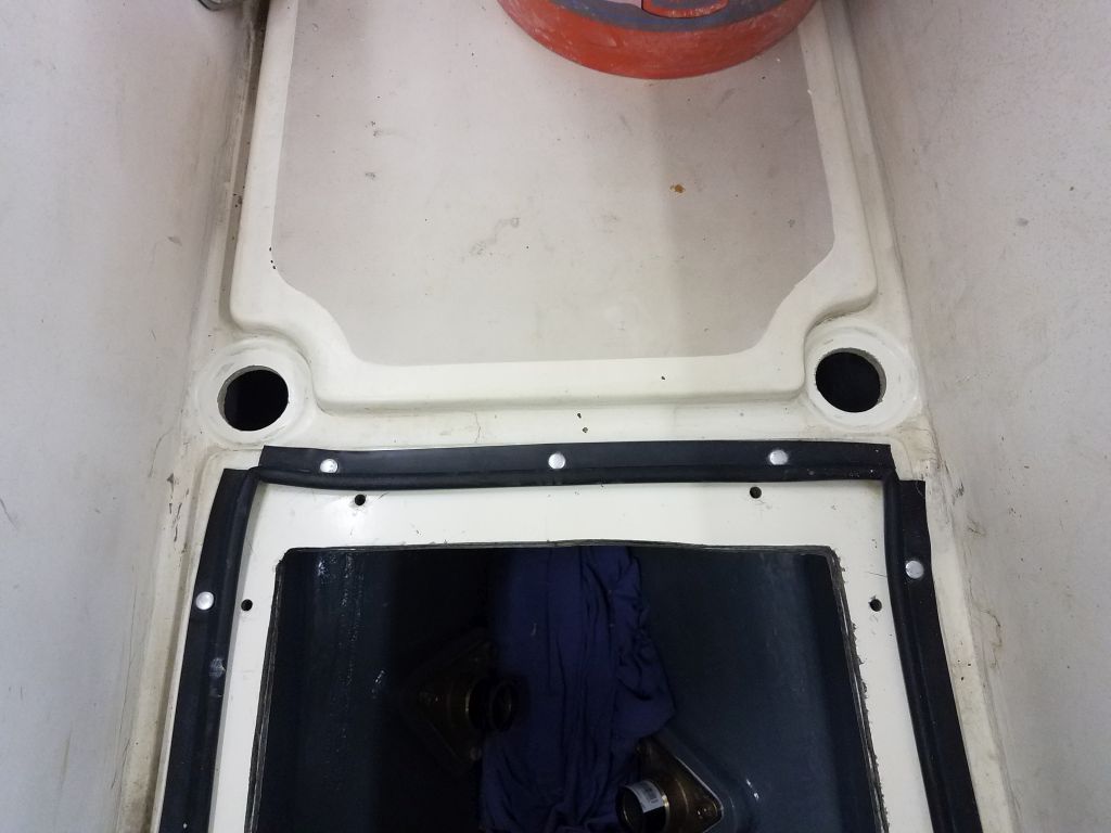
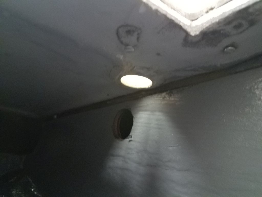
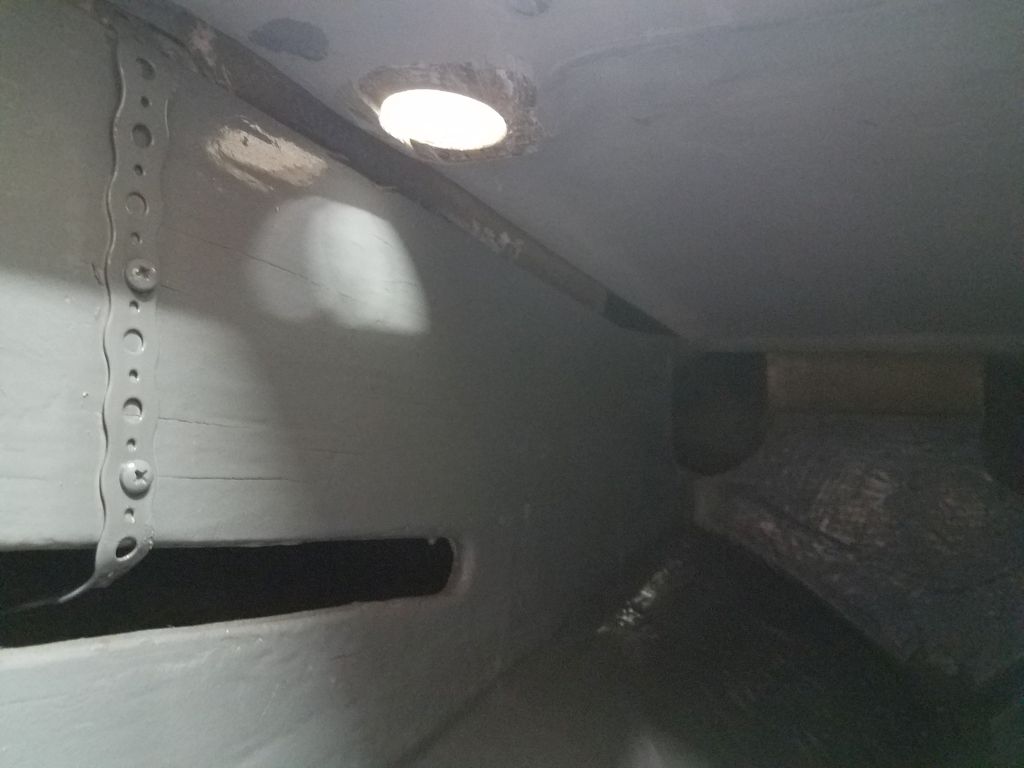
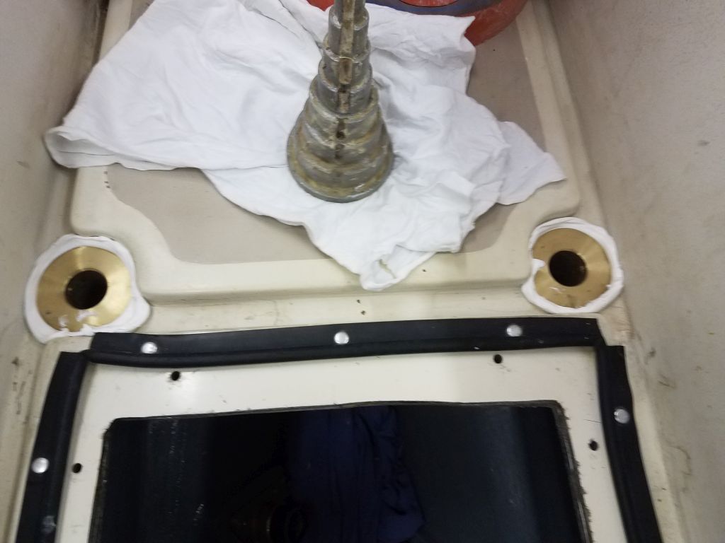
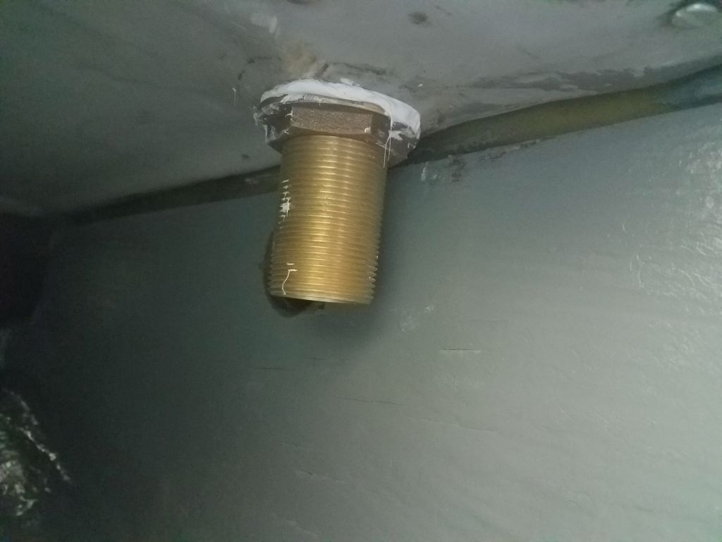
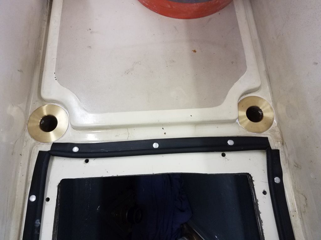
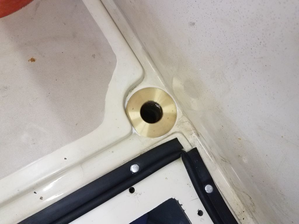
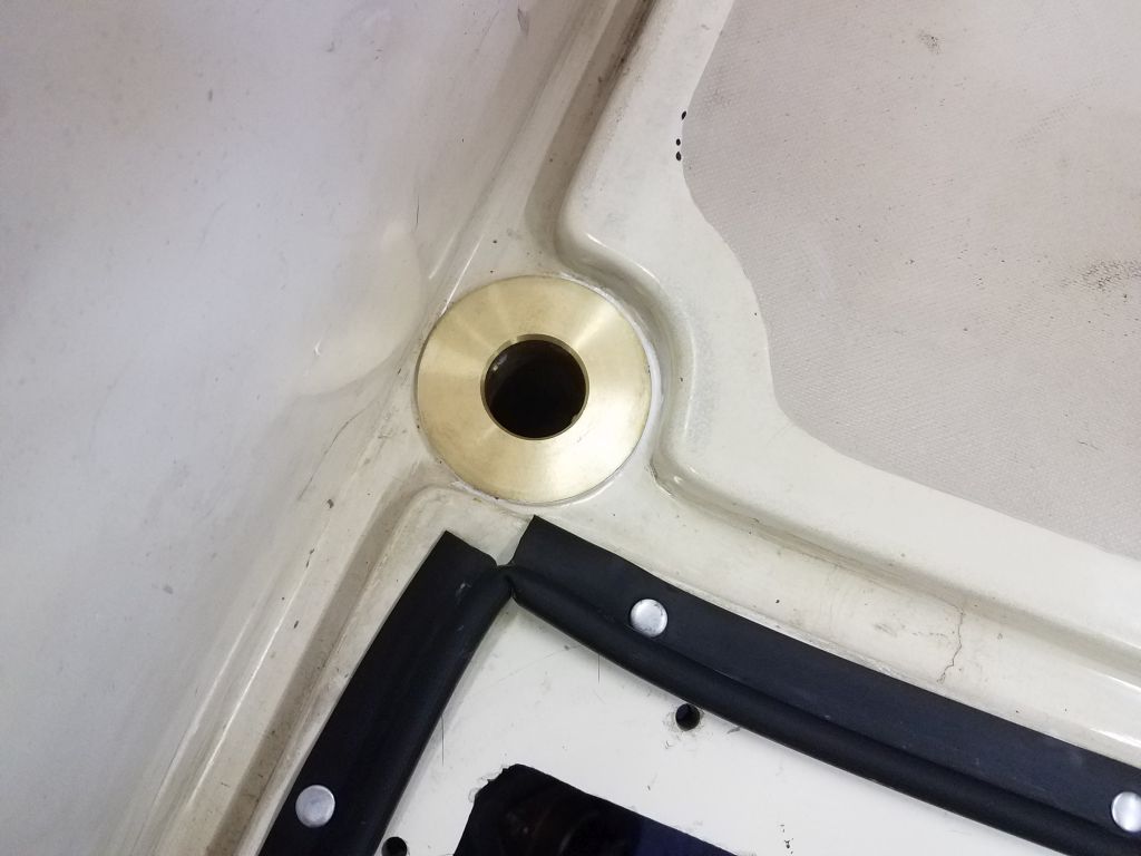
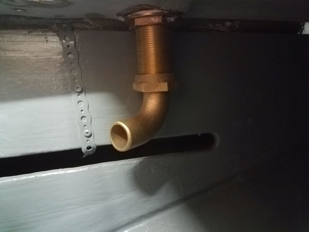
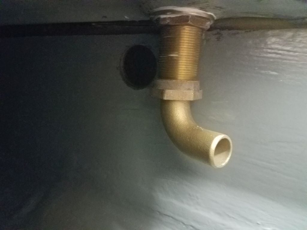
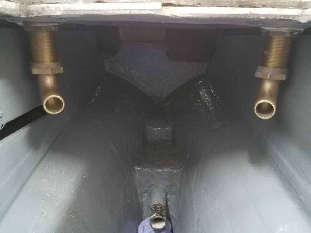
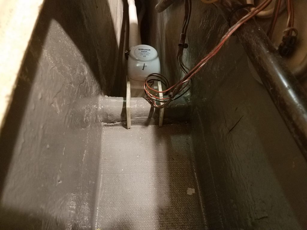
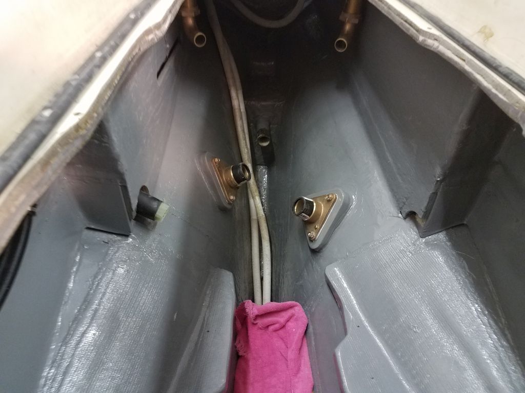
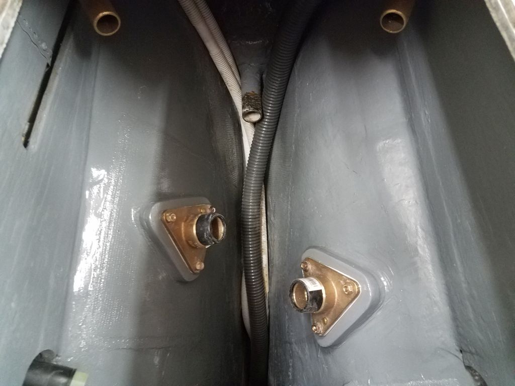
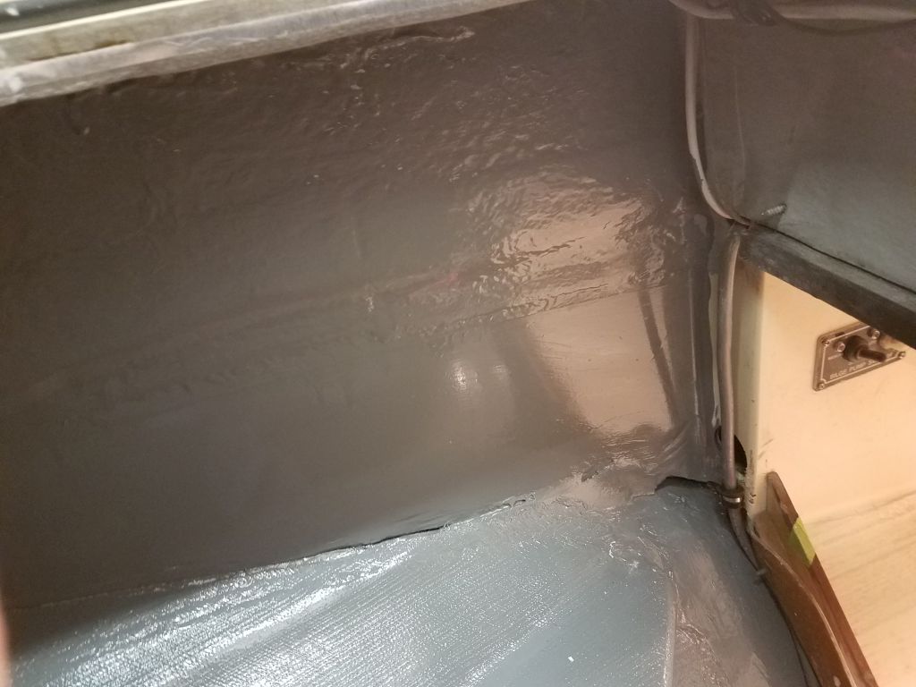
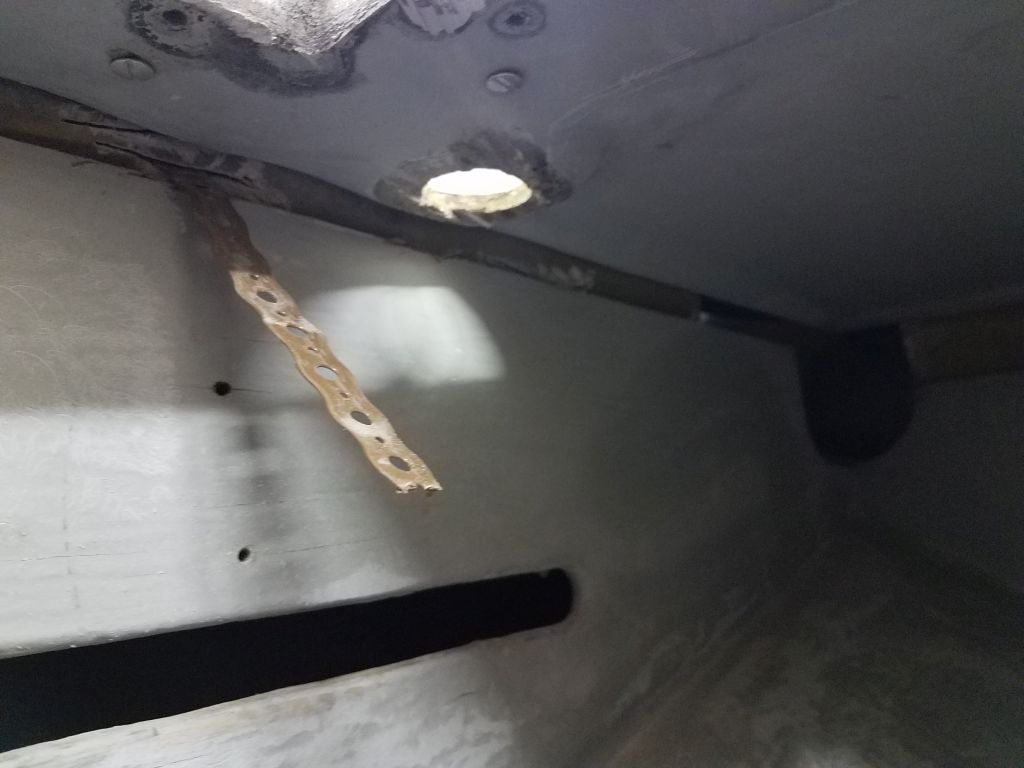
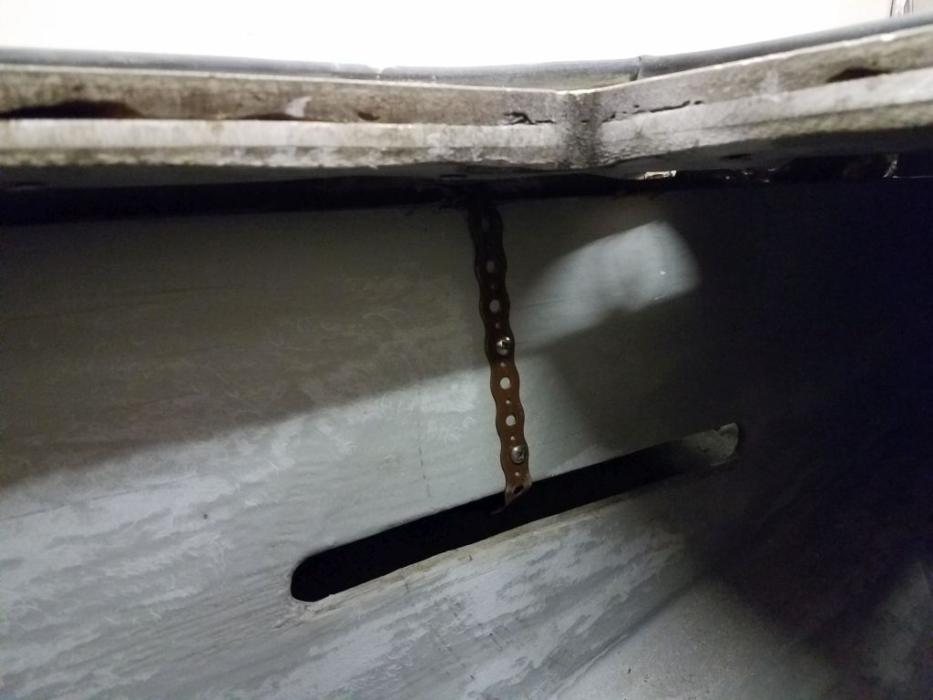
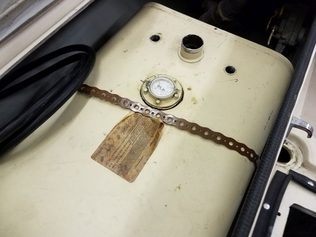
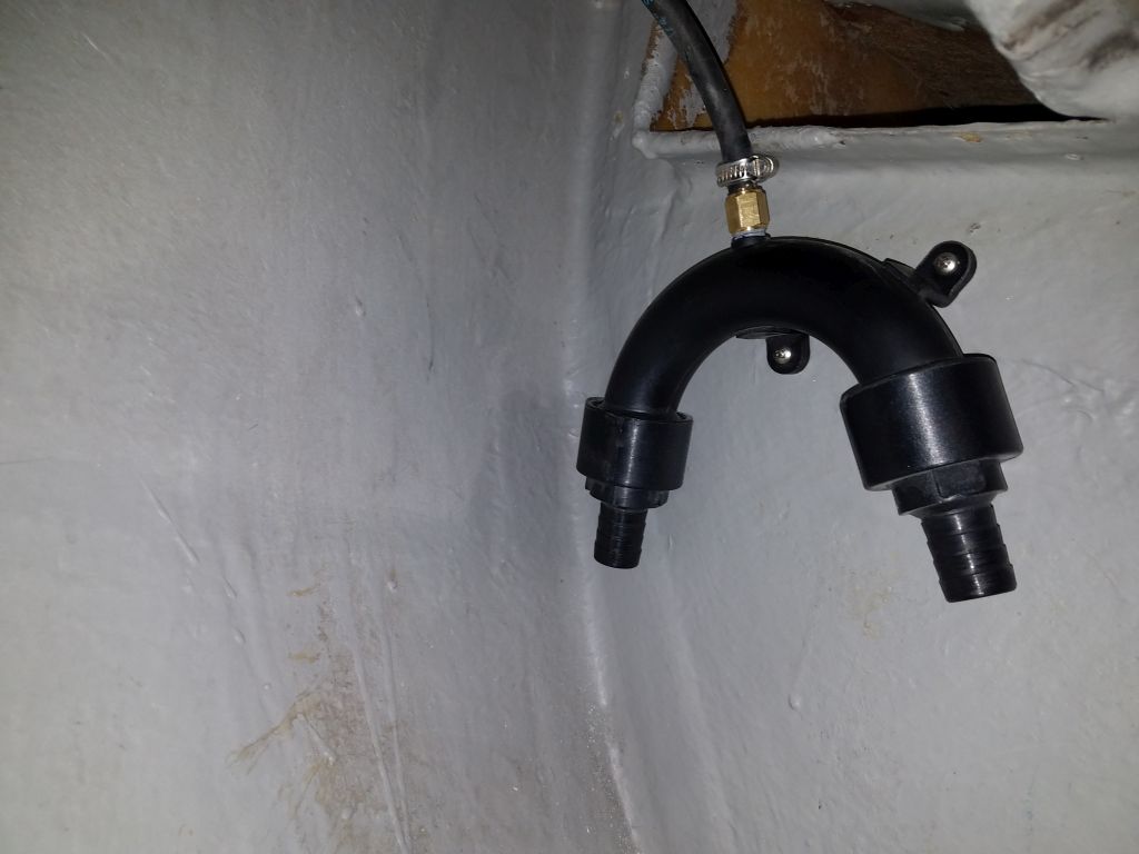
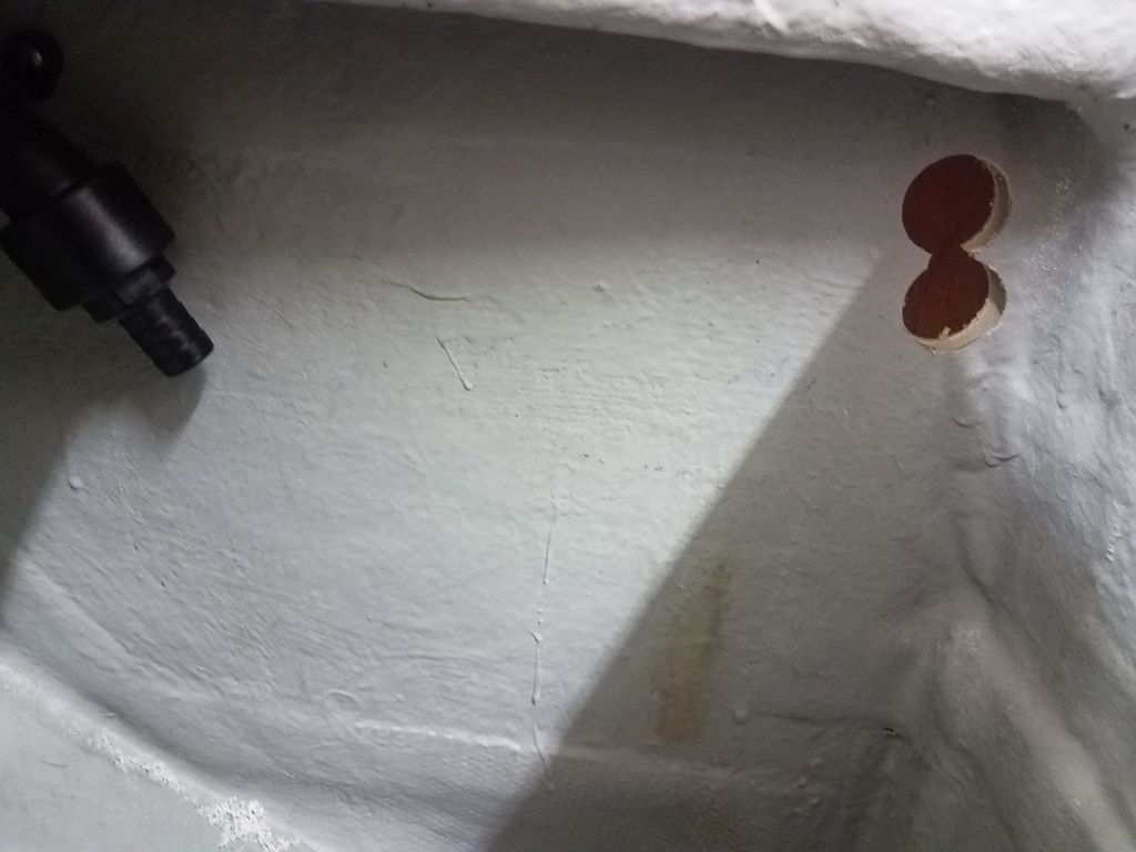
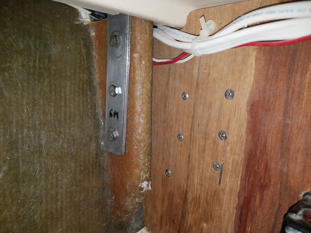
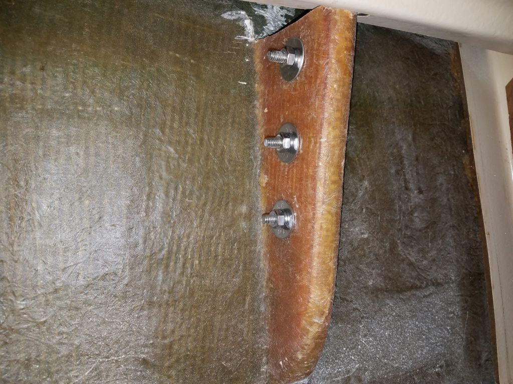
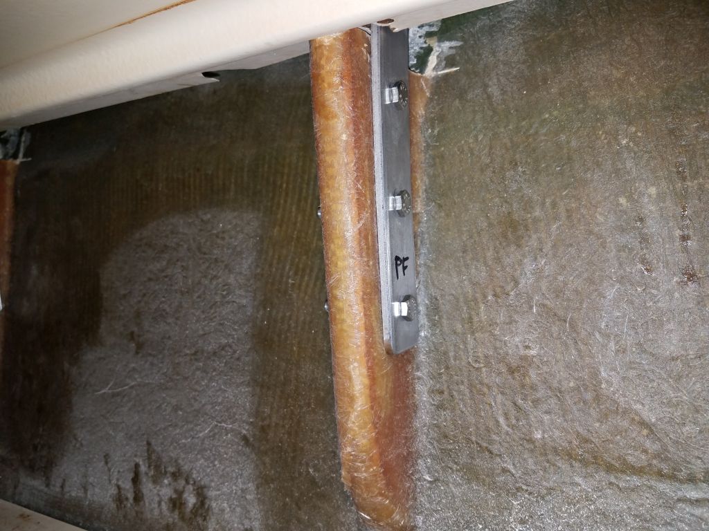
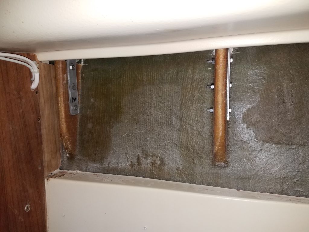
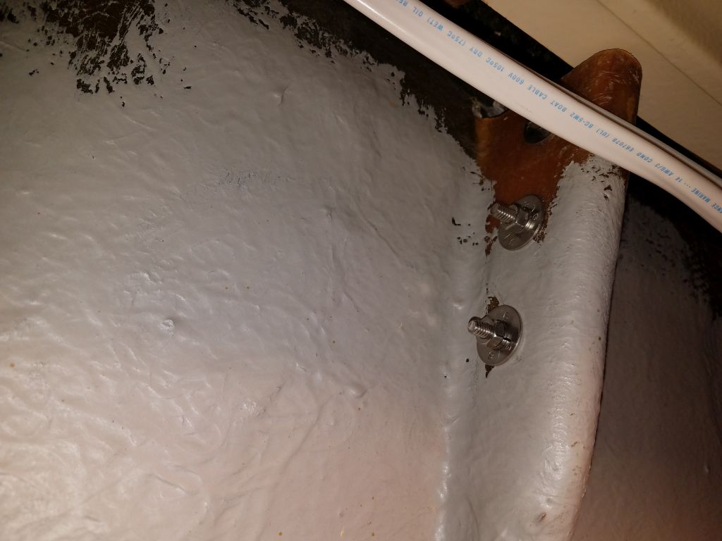
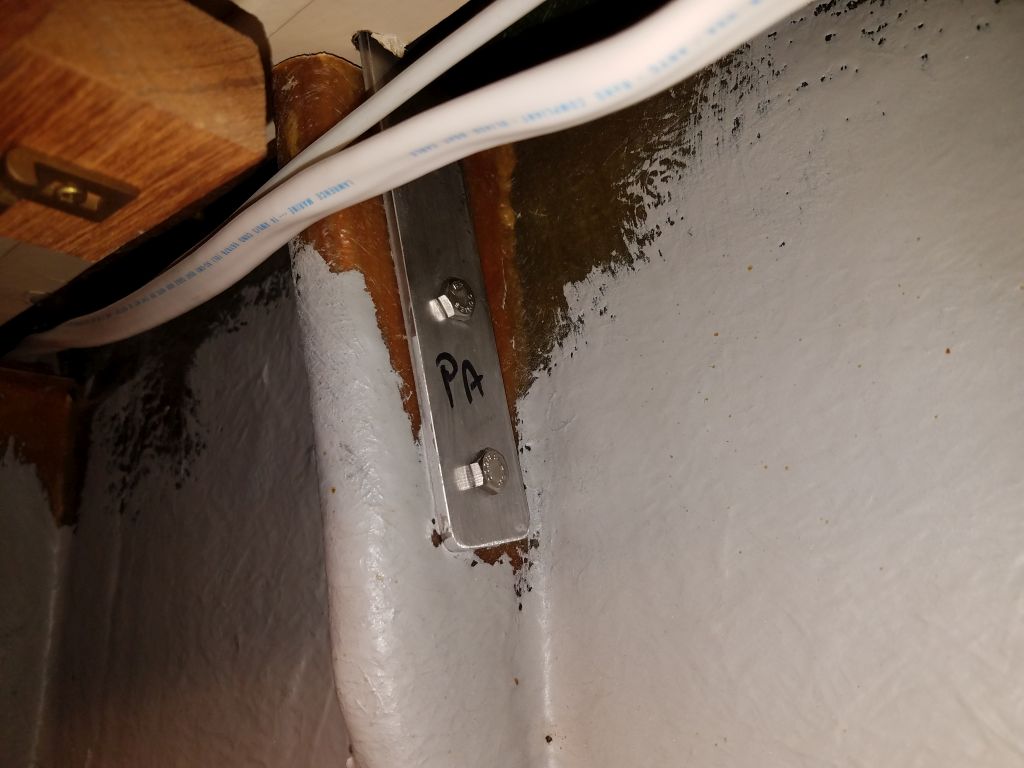
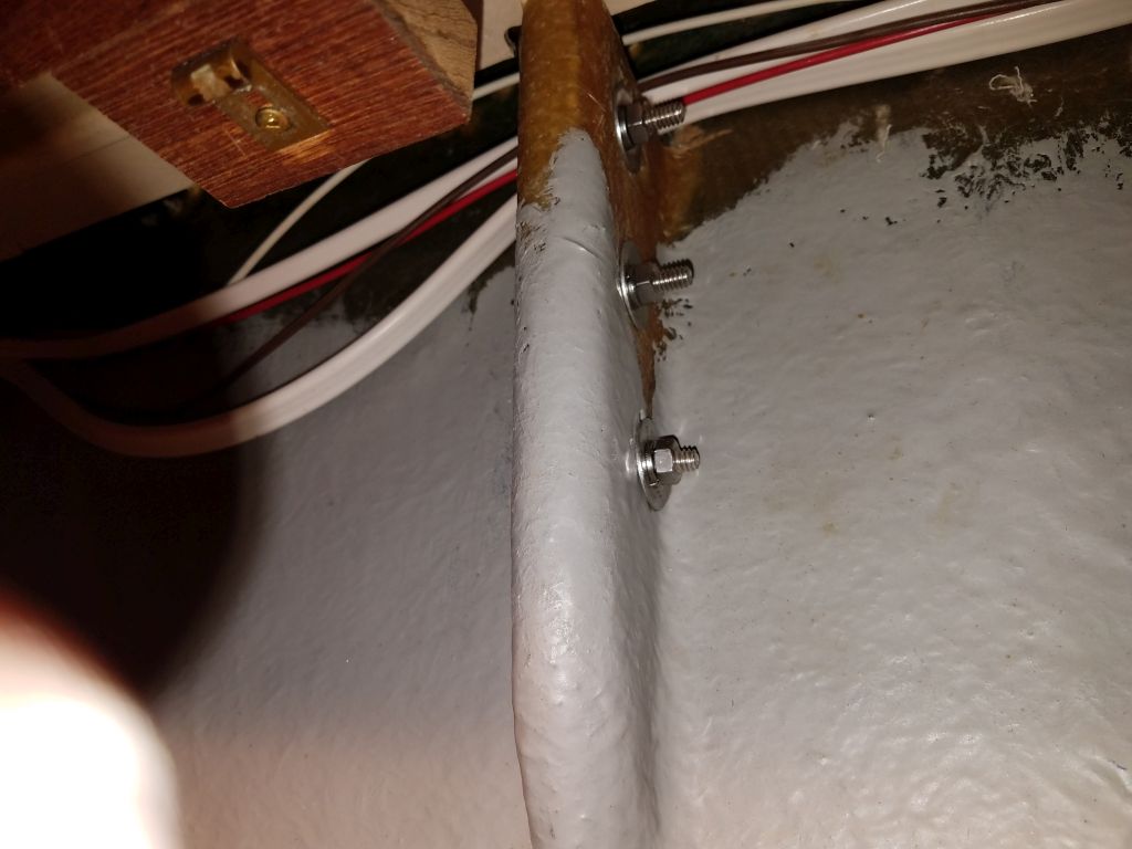
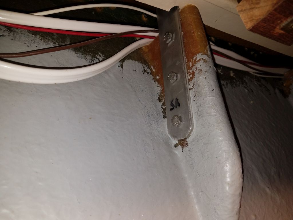
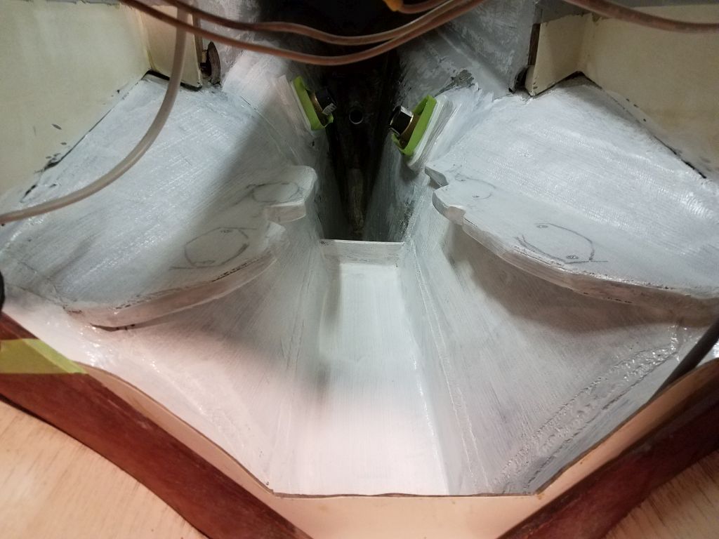
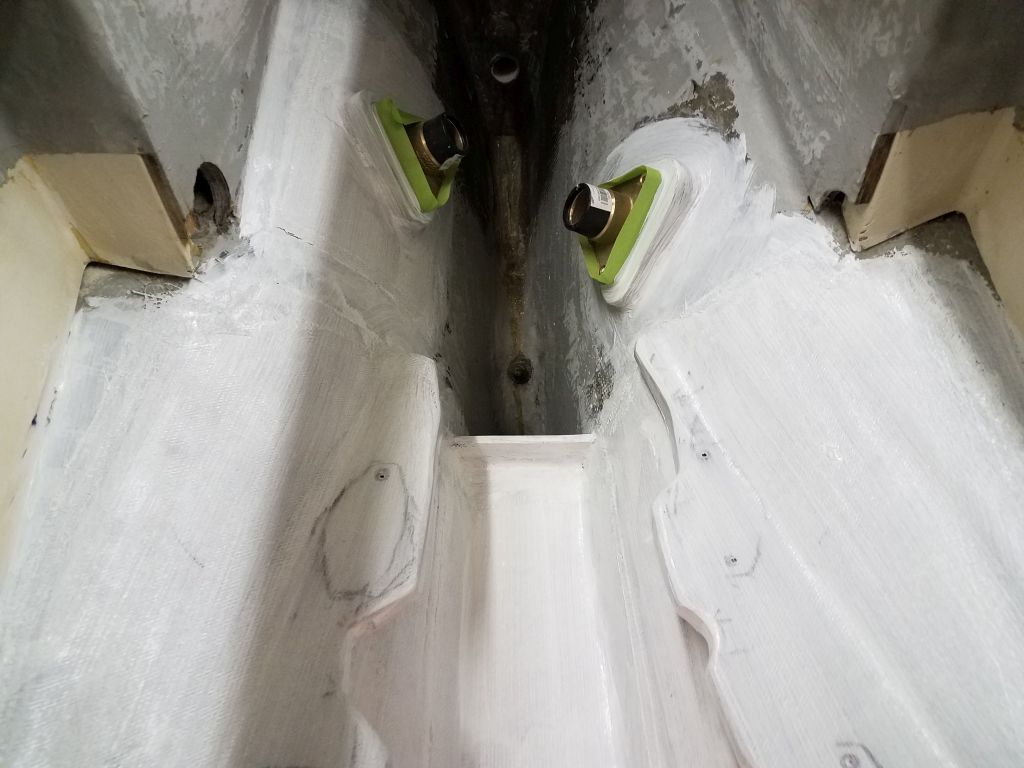
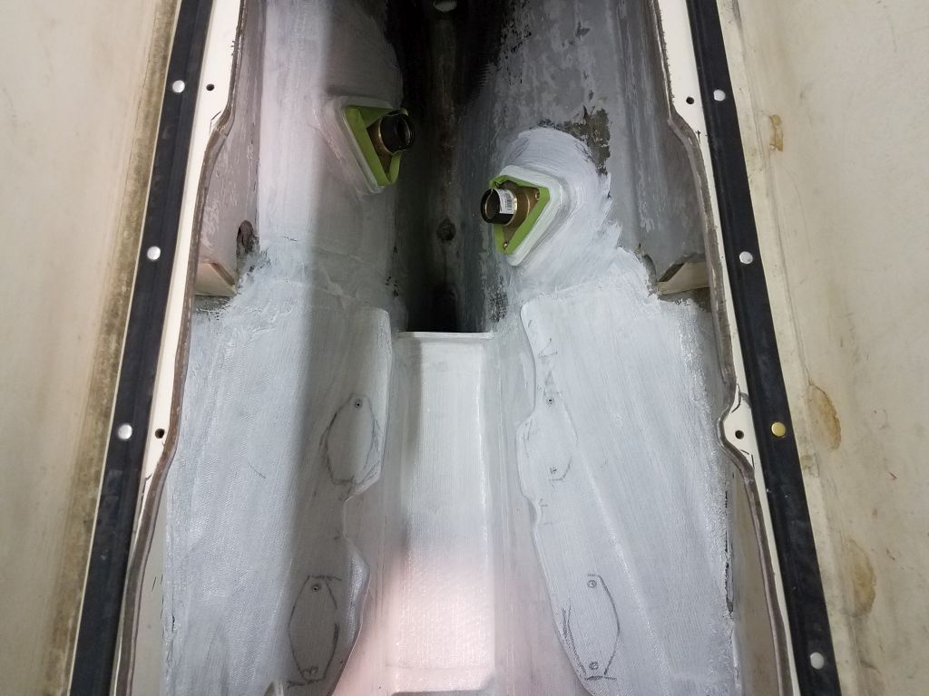
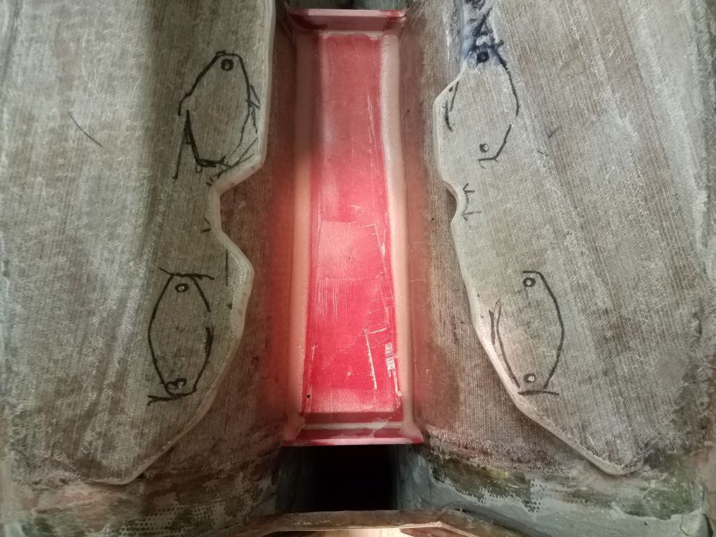
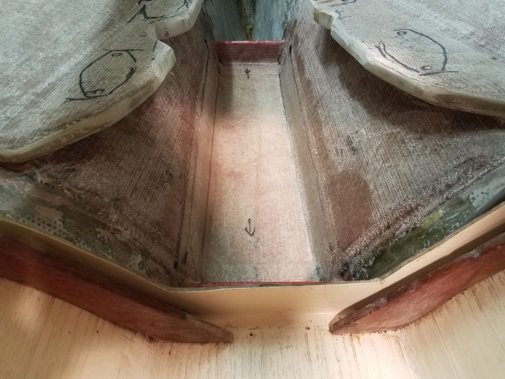
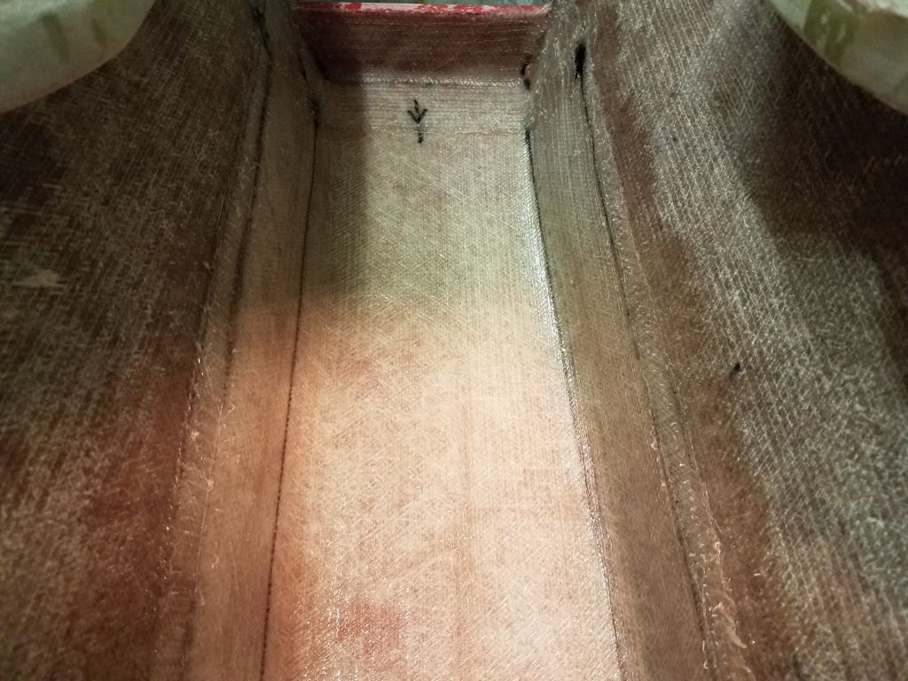
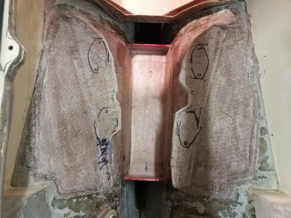
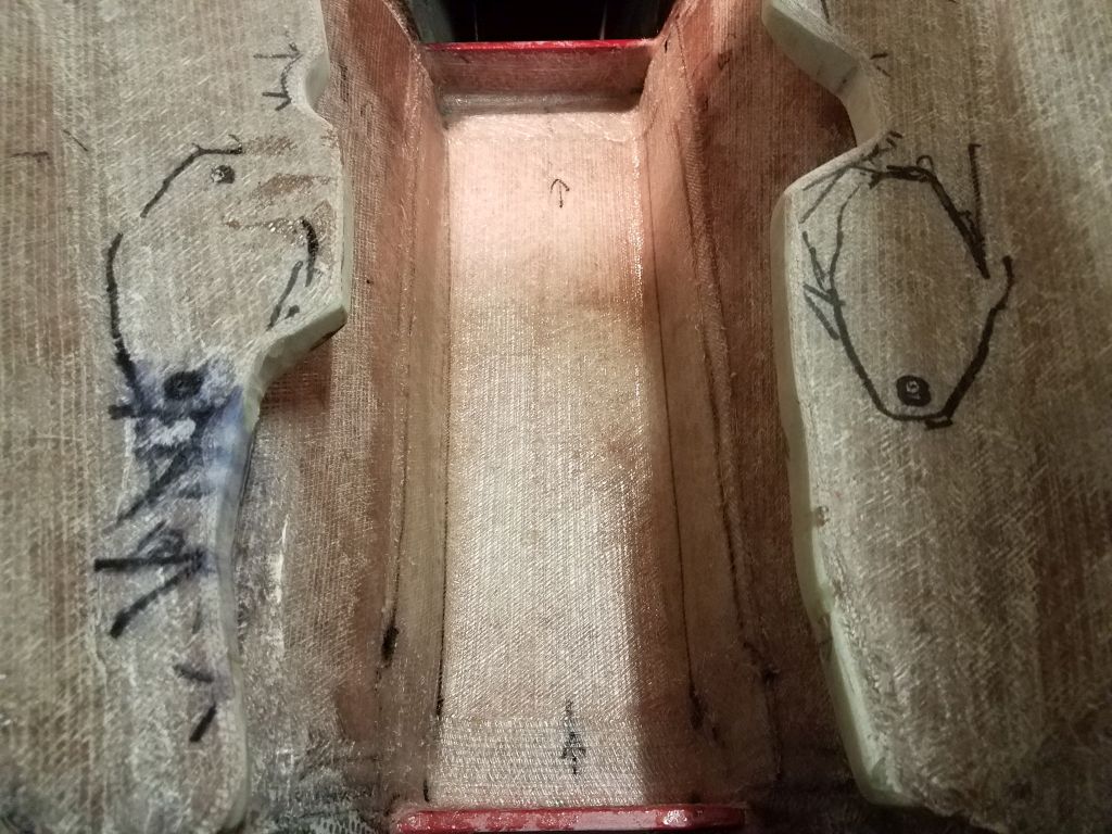
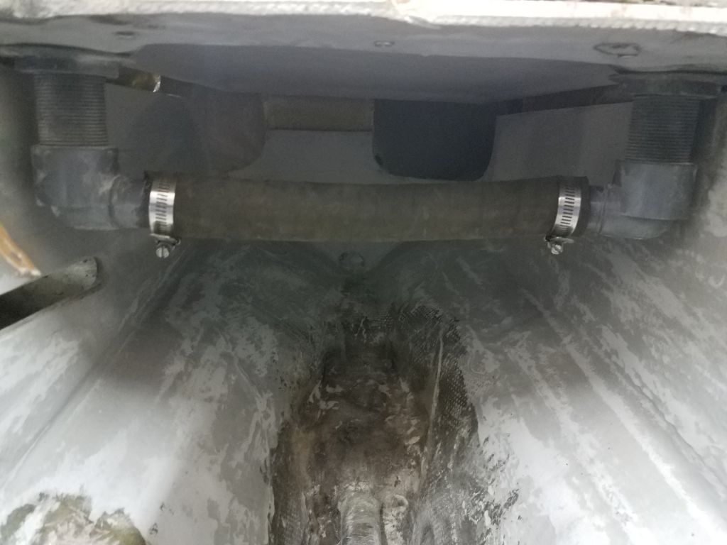
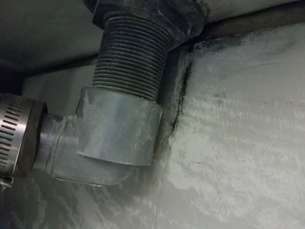
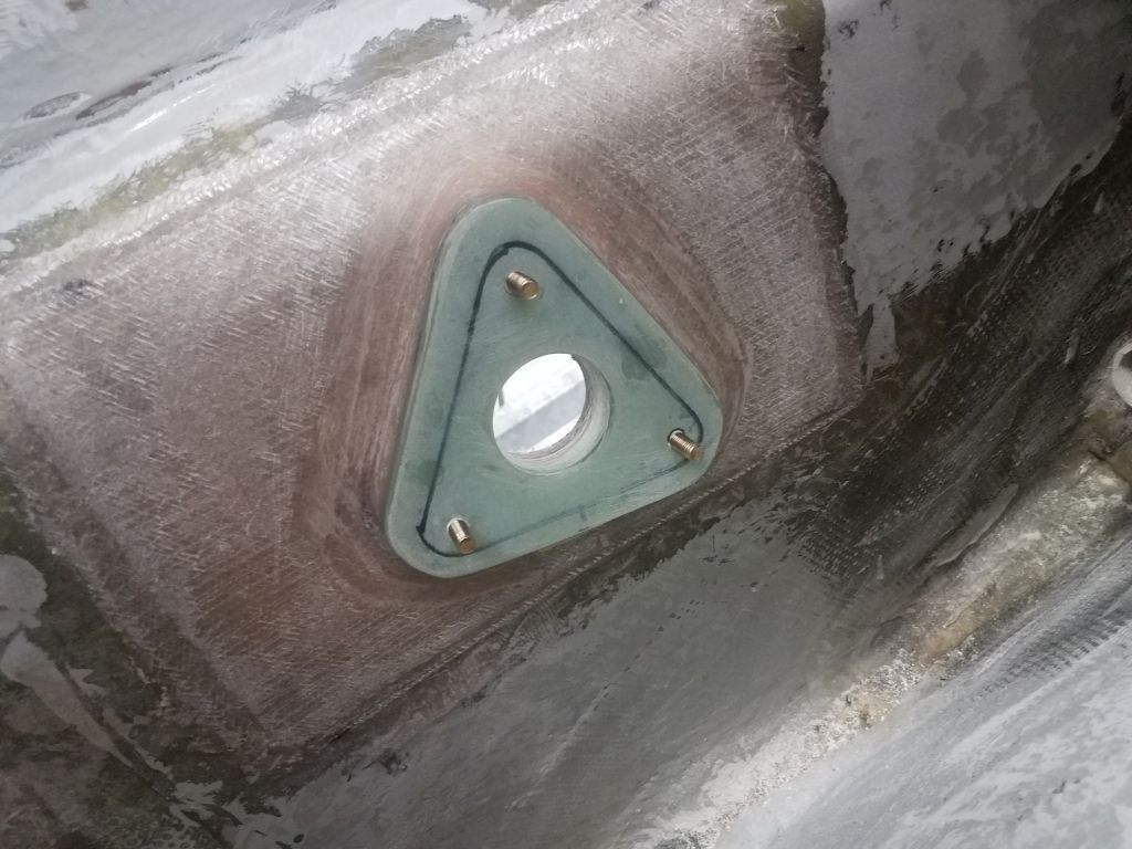
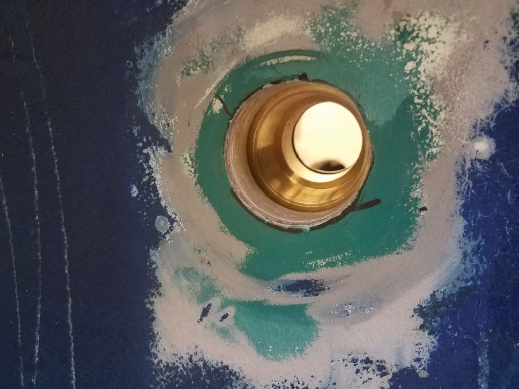
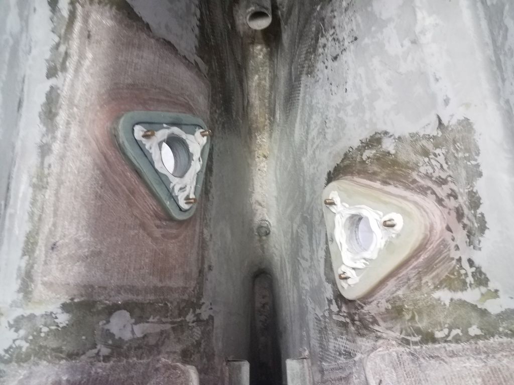
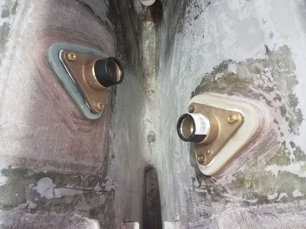
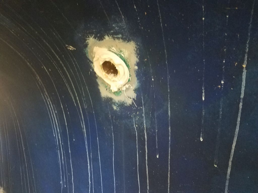
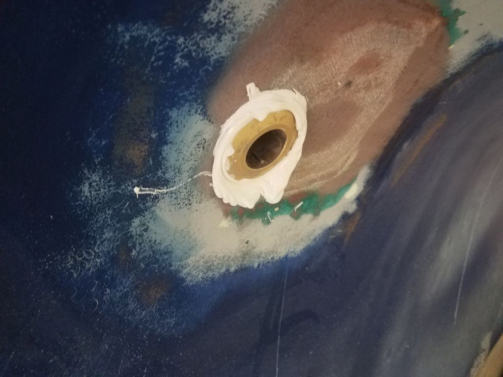
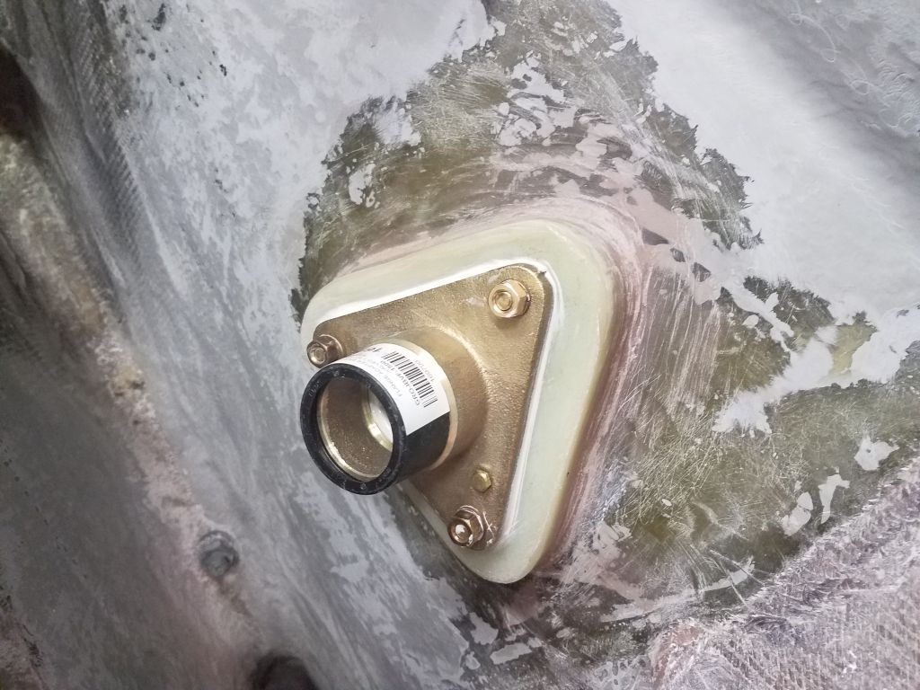
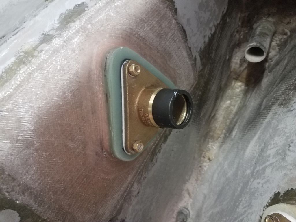
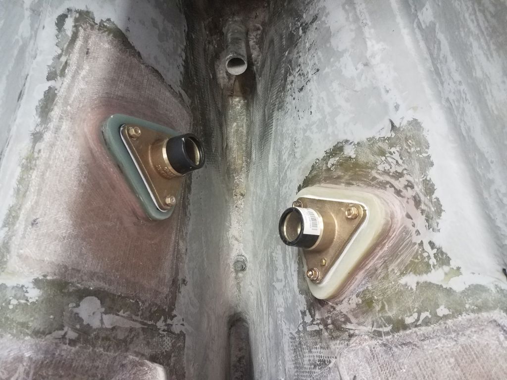
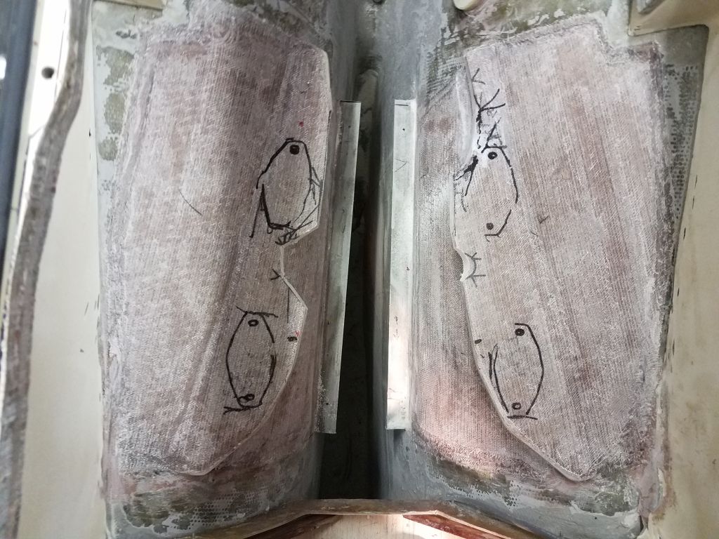
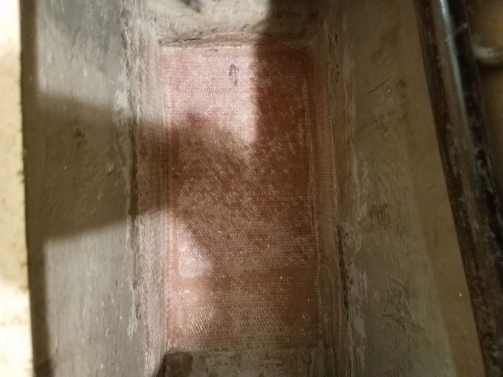
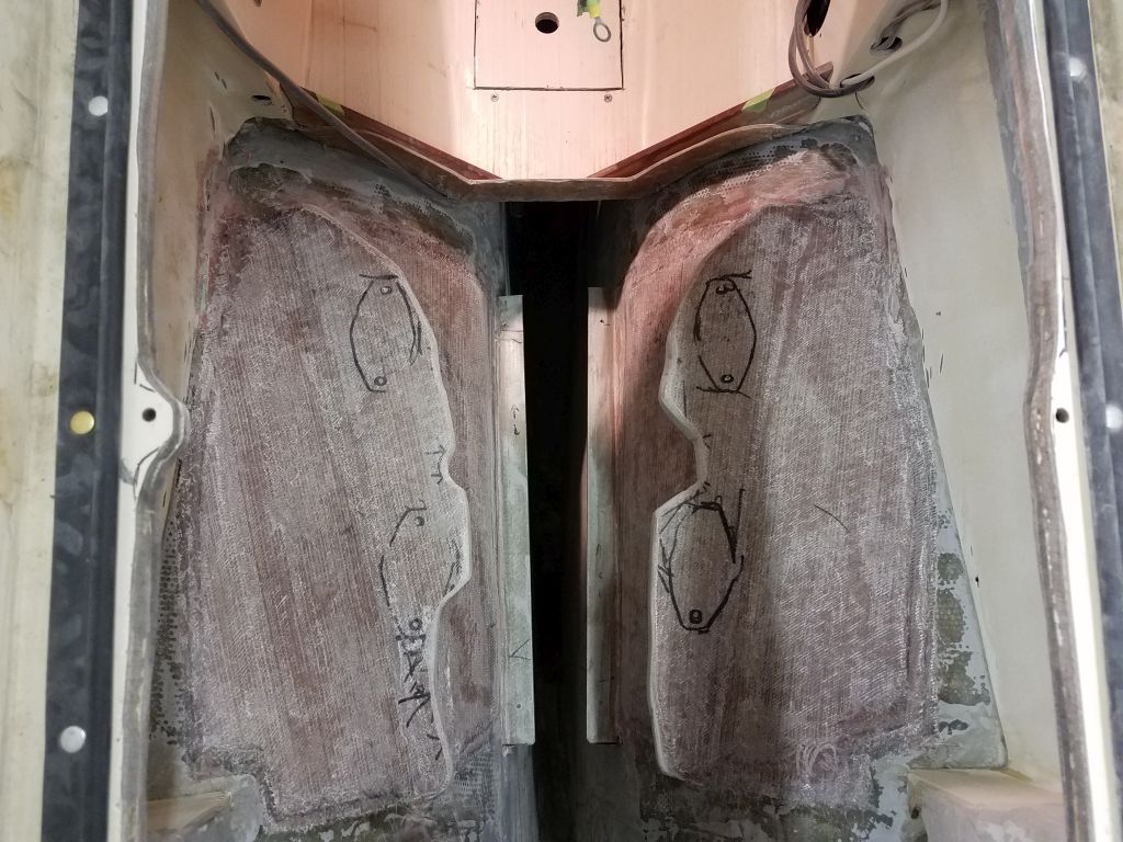
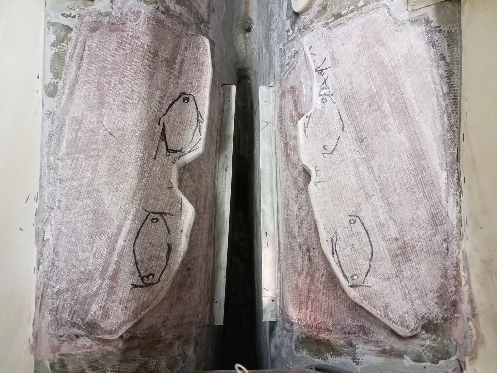
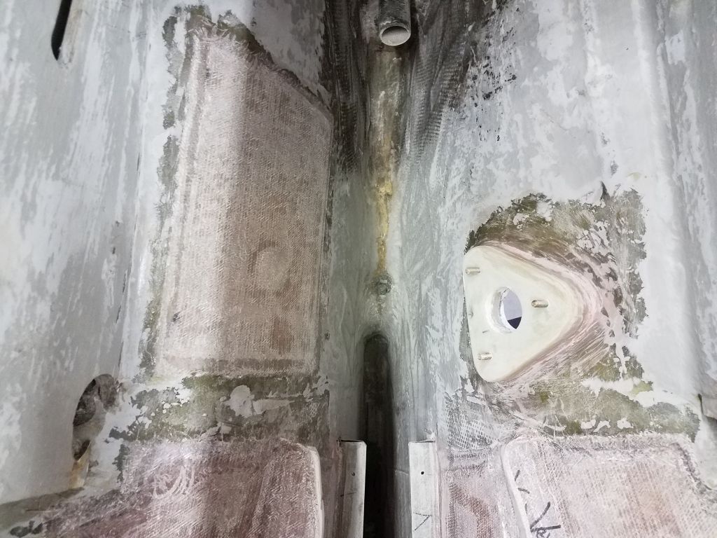
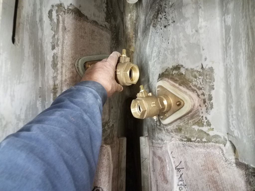
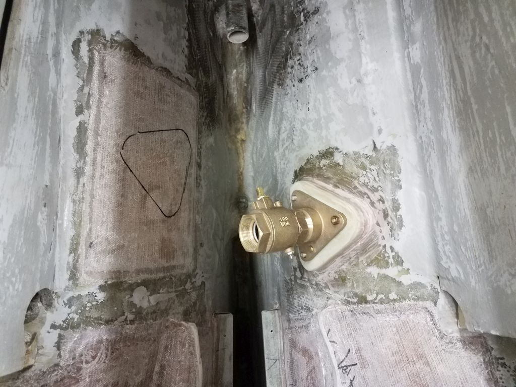
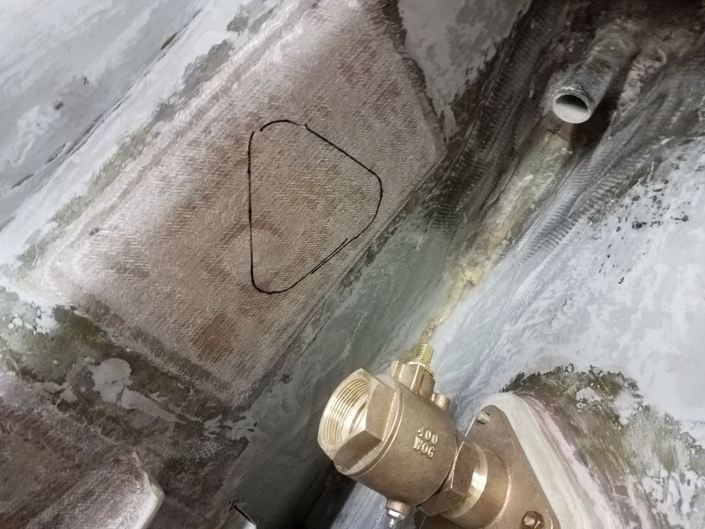
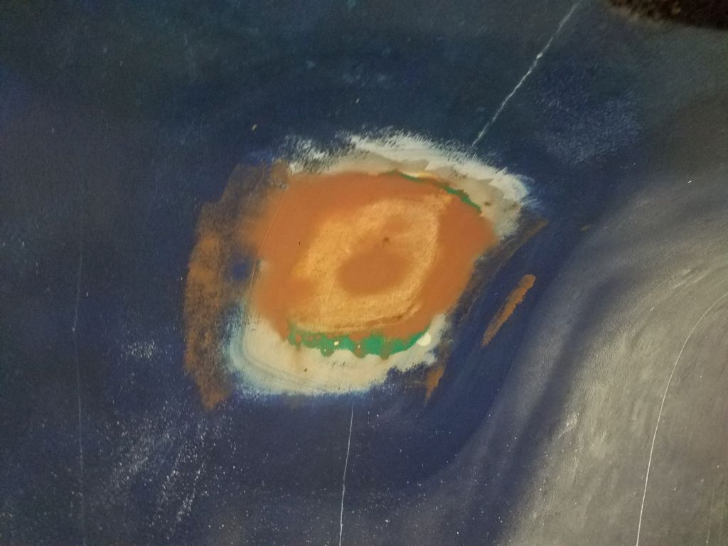
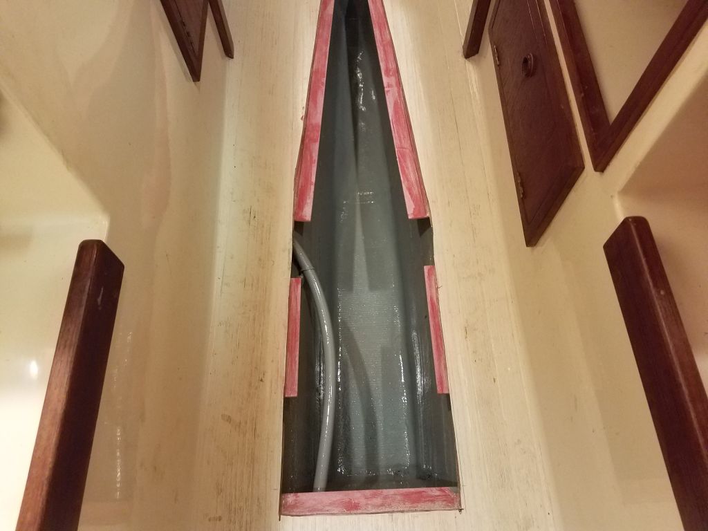
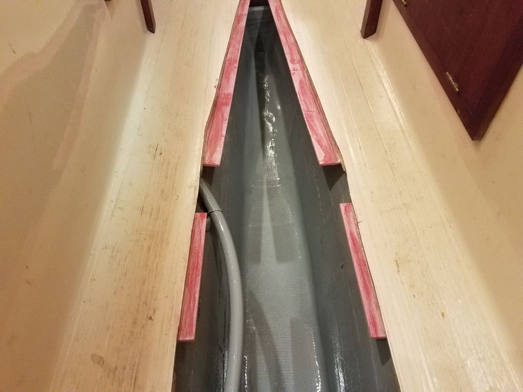
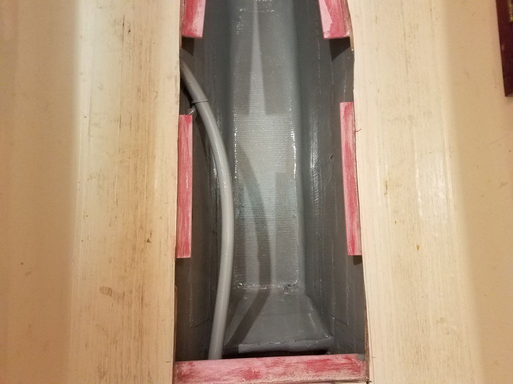
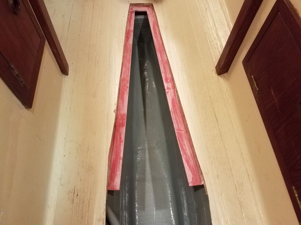
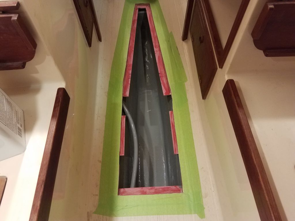
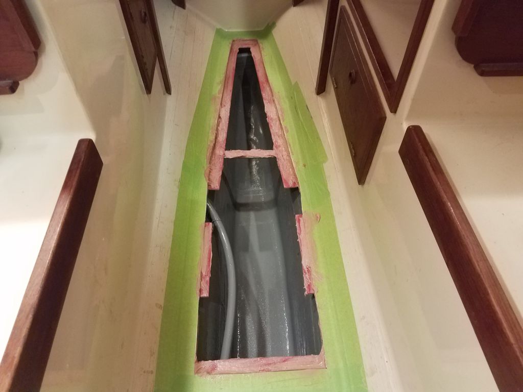
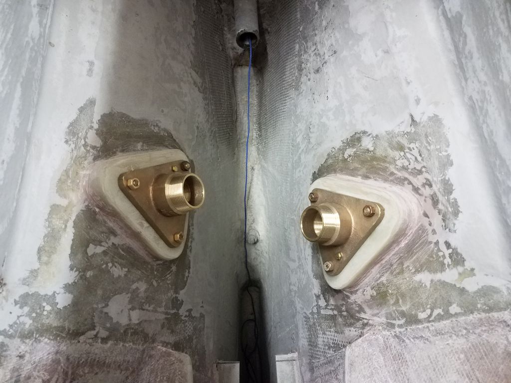
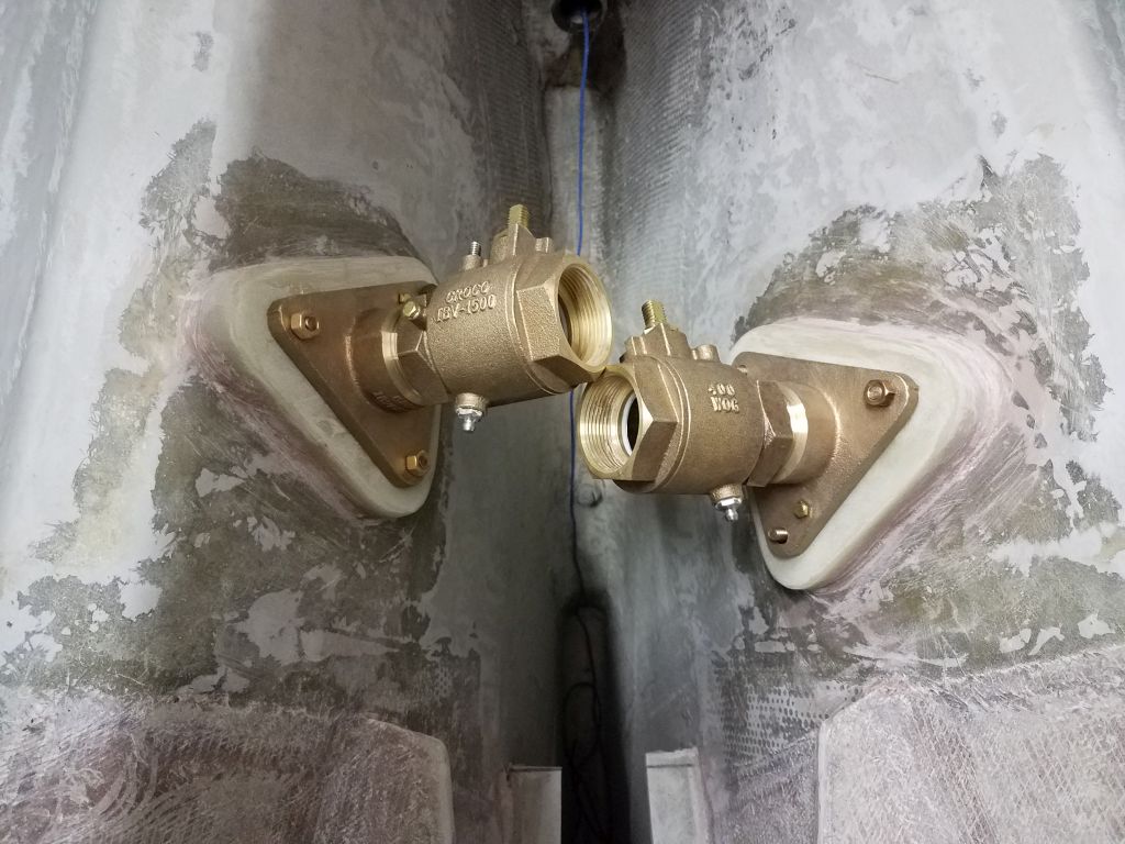
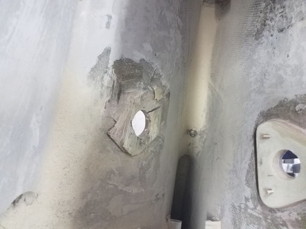
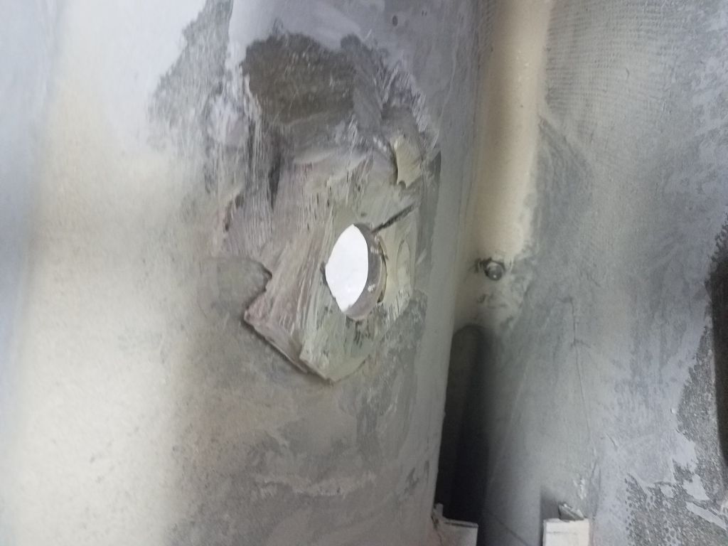
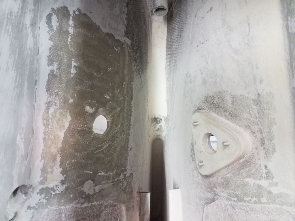
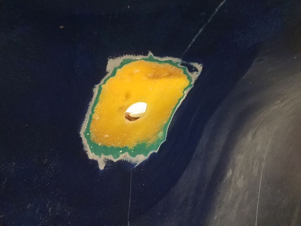
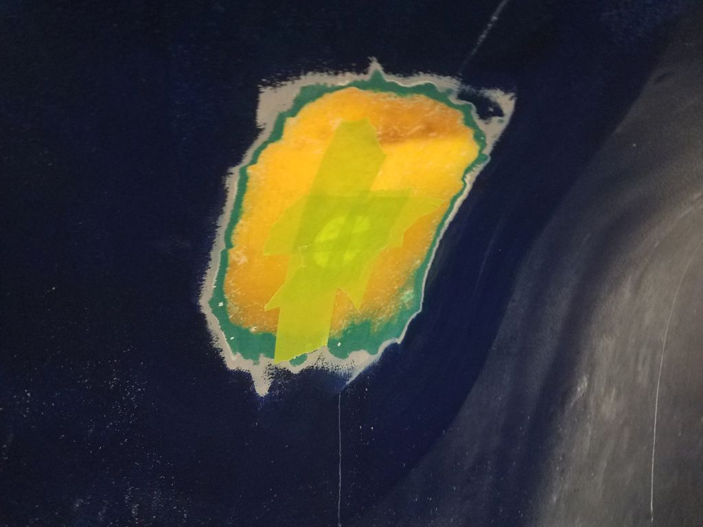
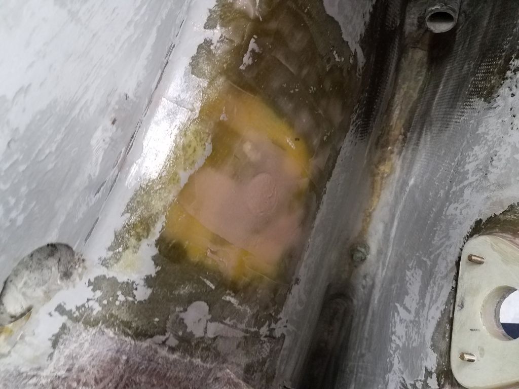
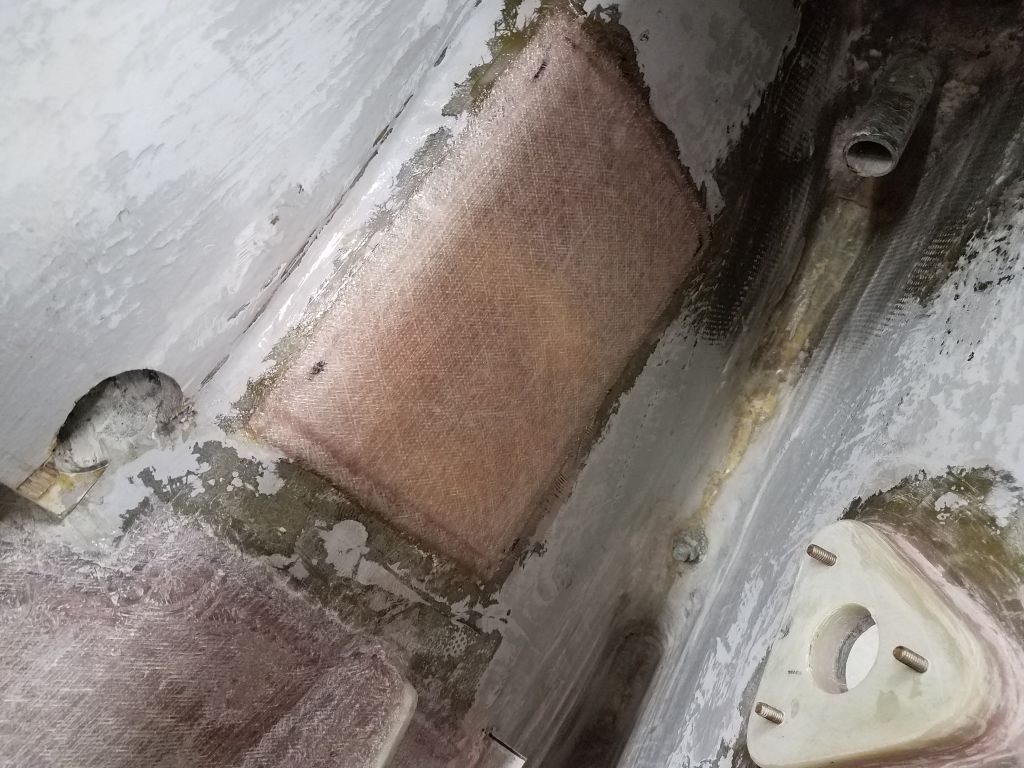
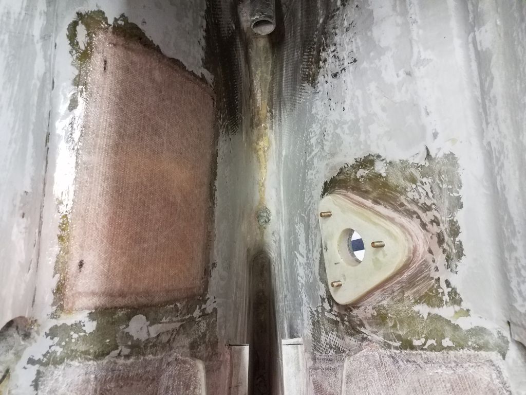
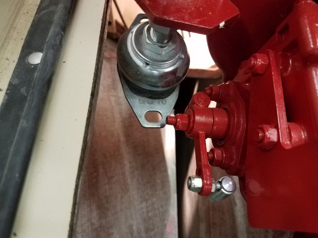
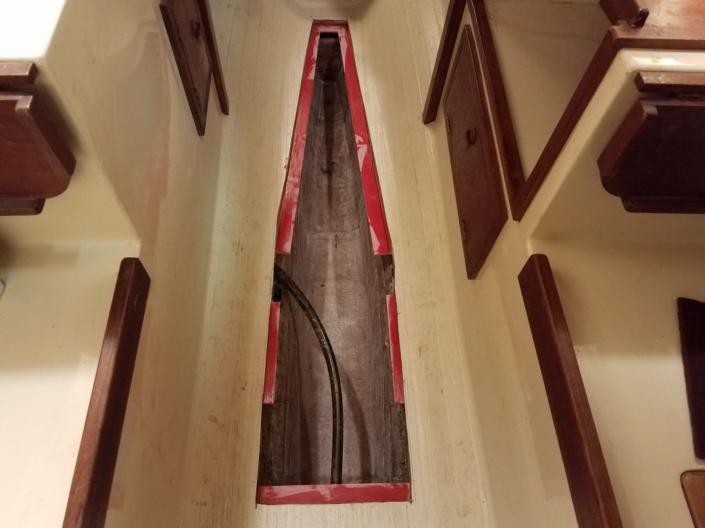
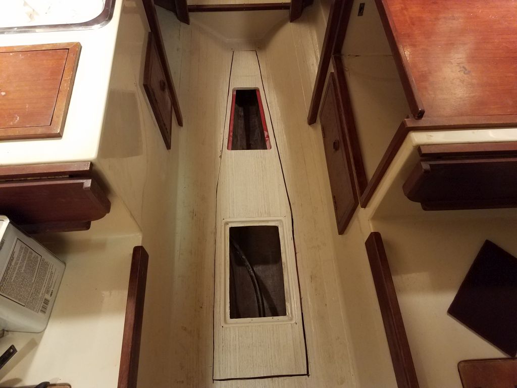
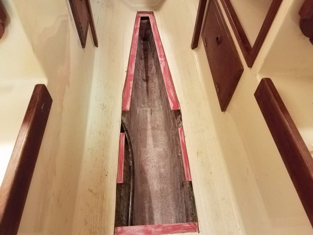
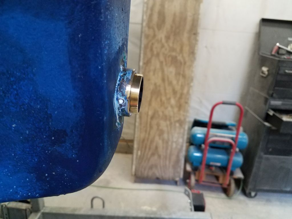
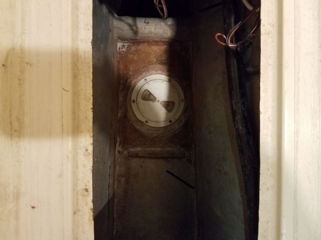
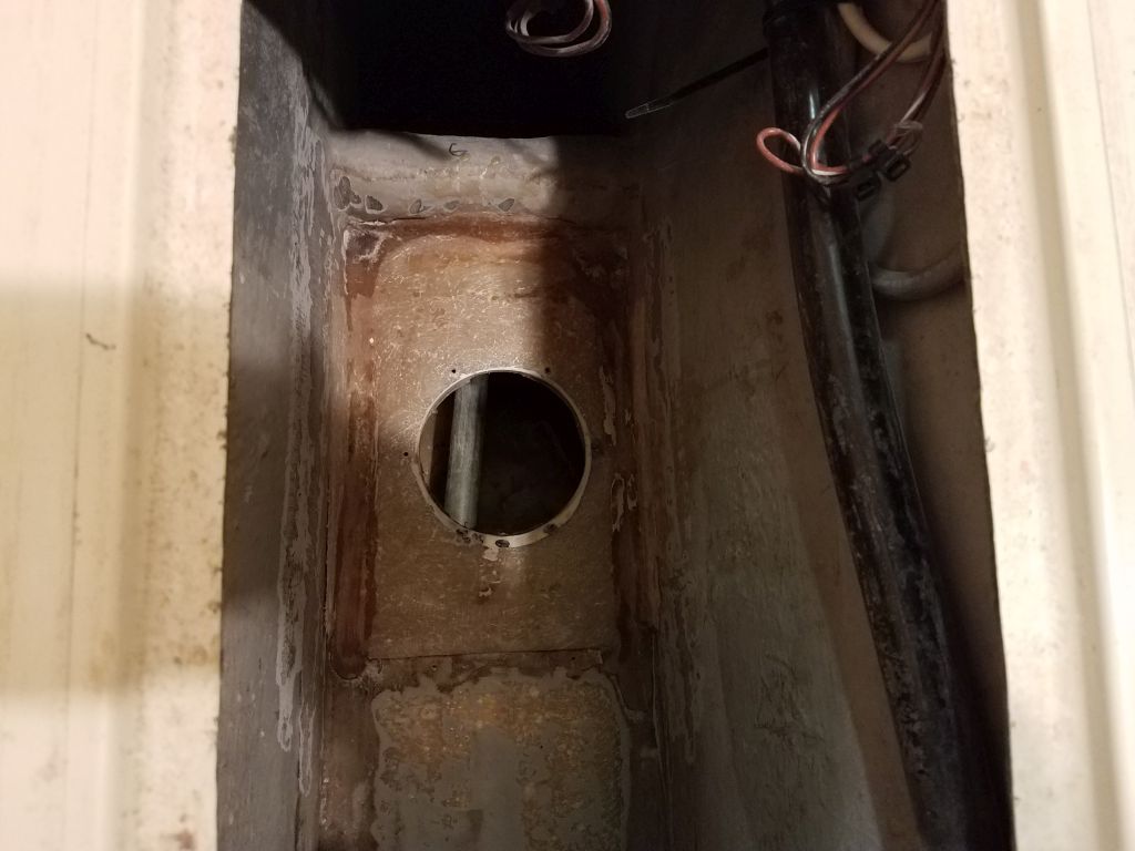
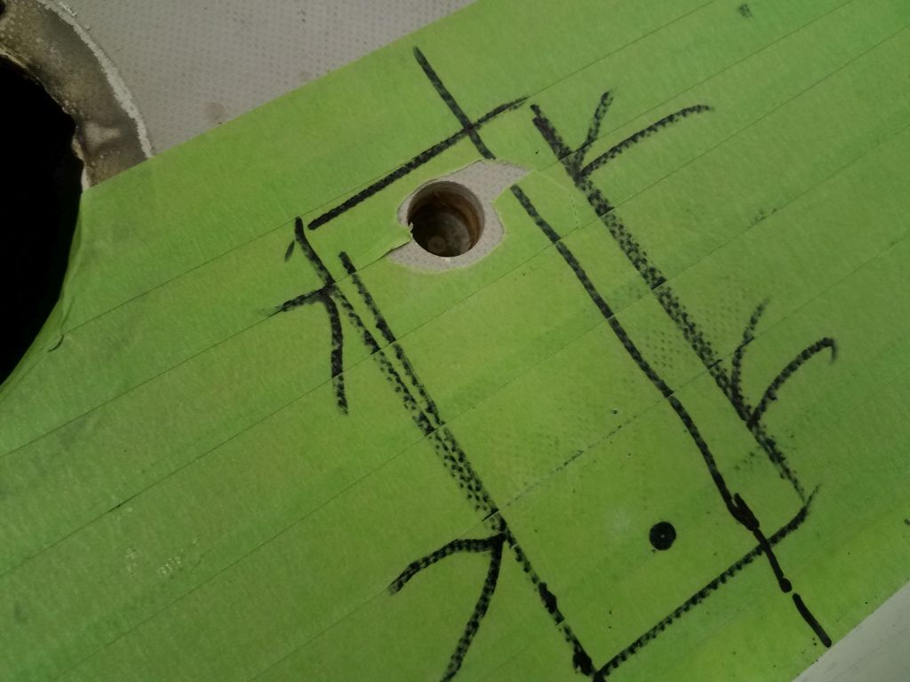
On the boat, I marked the bolt hole positions for the two tube brackets, and with a 5/8″ bit I overbored the after hole on each side to remove the plywood core material; the forward pair of holes fell just forward of the end of the core (as I could determine by feeling around beneath the locations through the nearby vent fitting holes).  I filled the voids with a thickened epoxy mixture and left the potted holes to cure overnight.

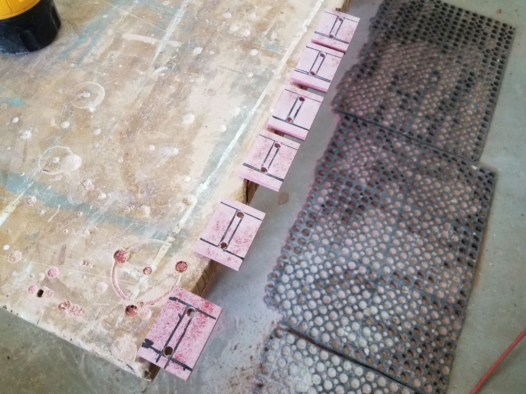
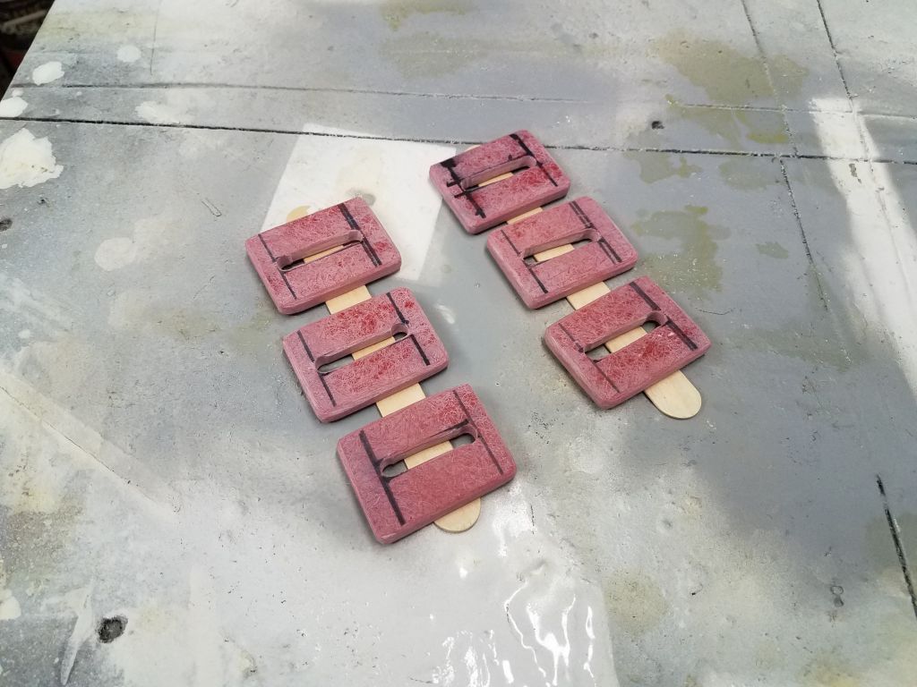
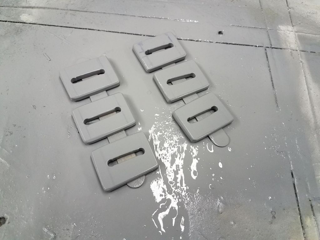
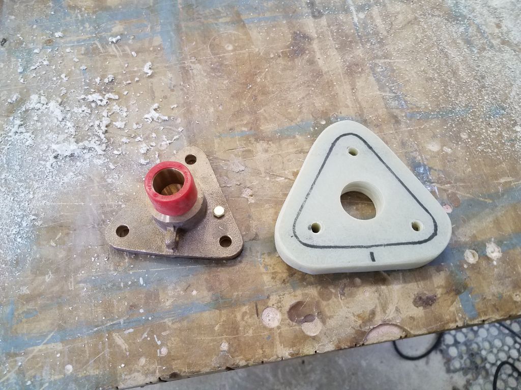
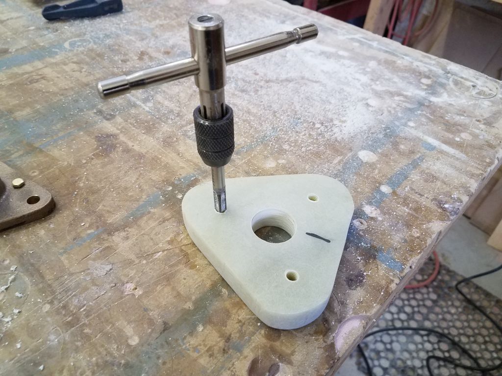
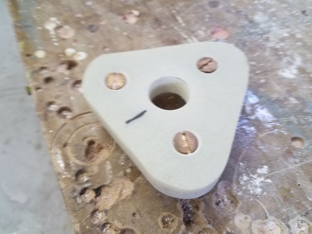
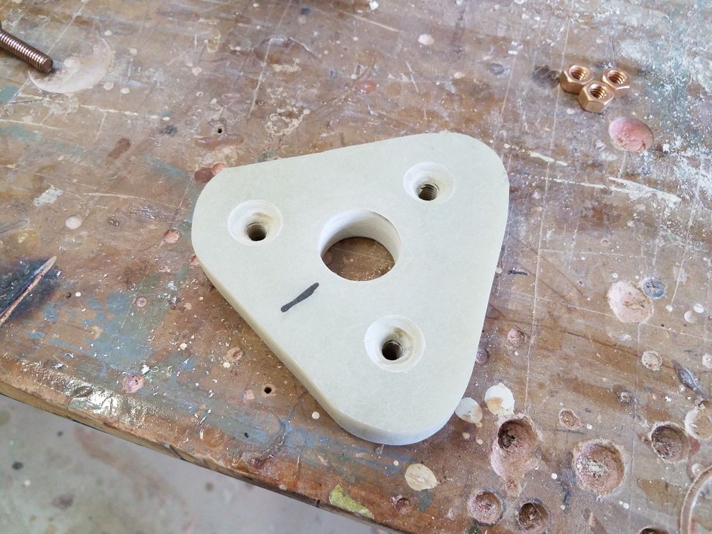
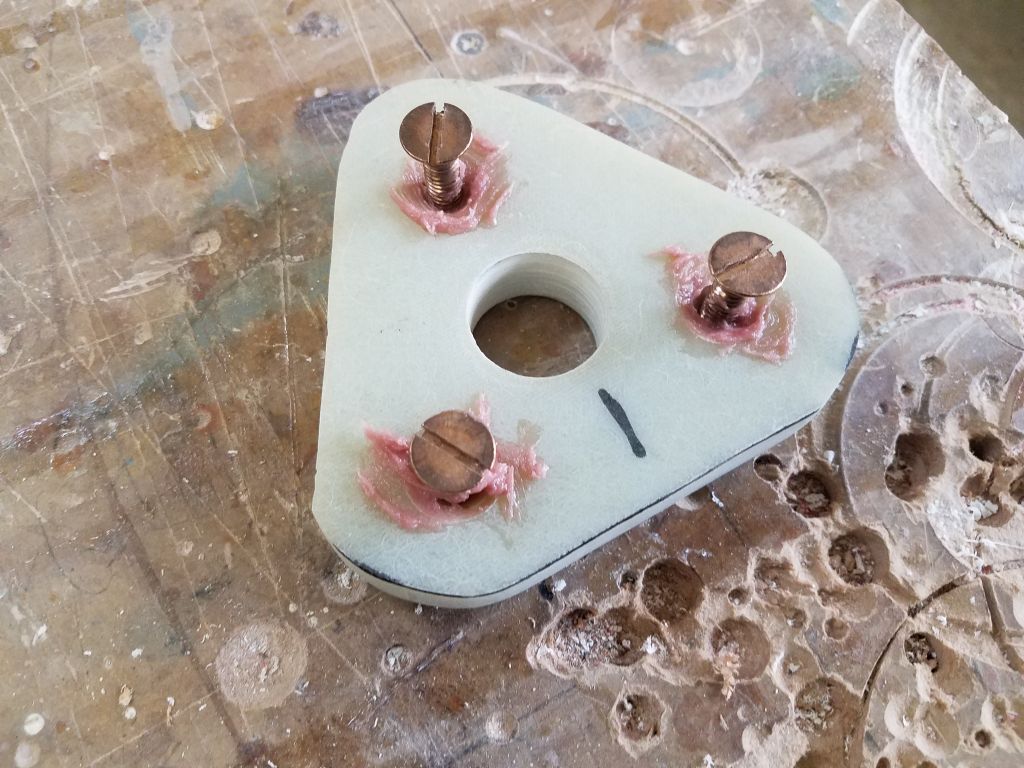
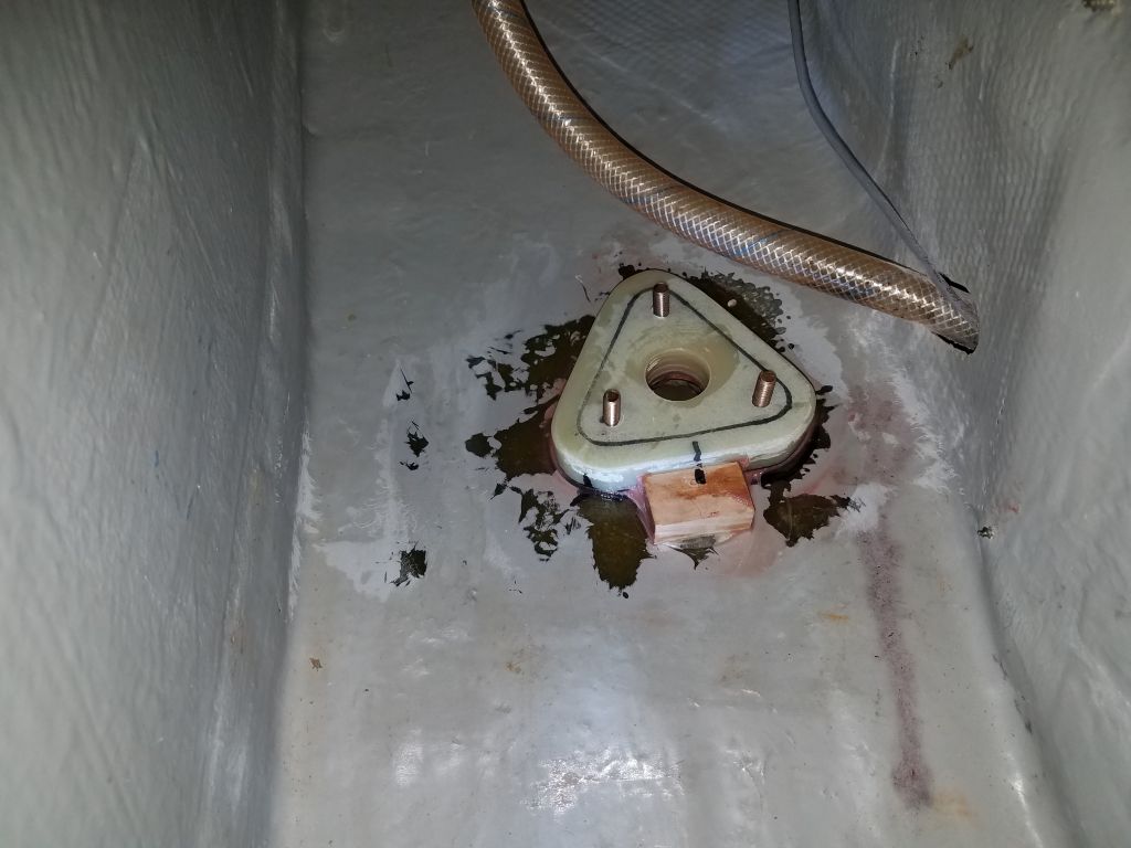
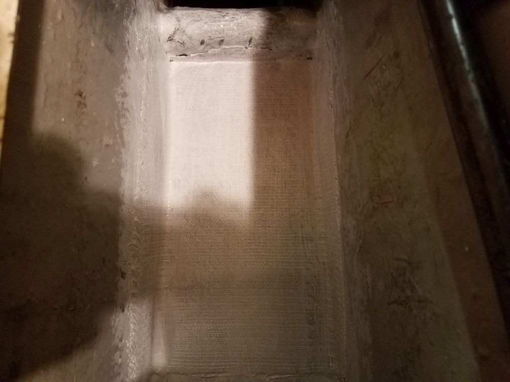
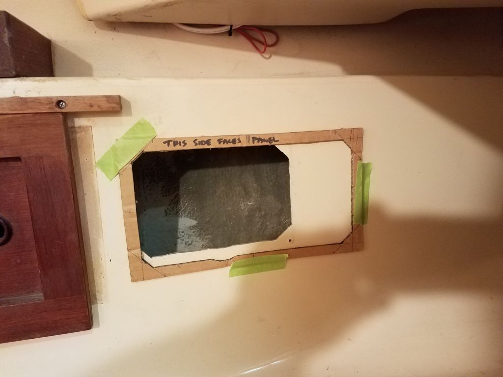
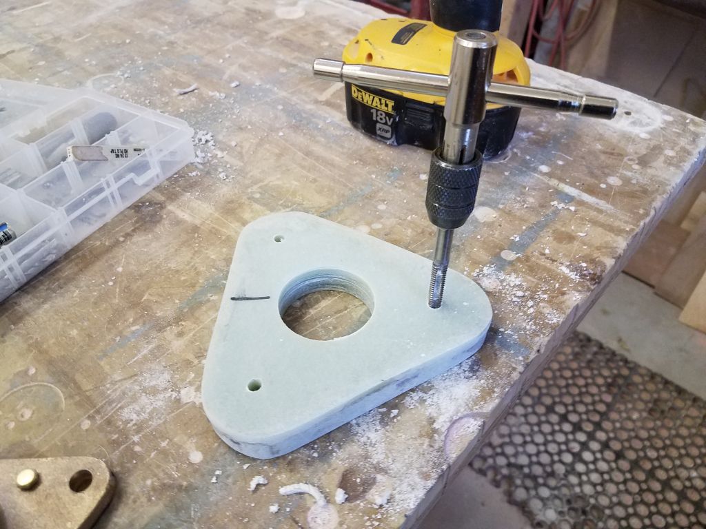
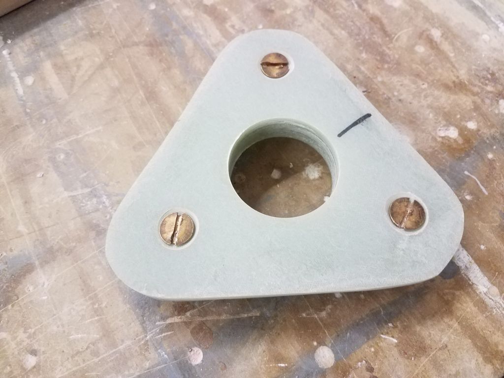
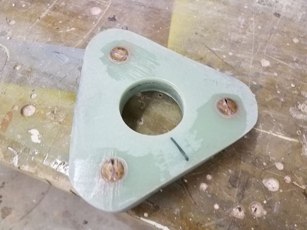
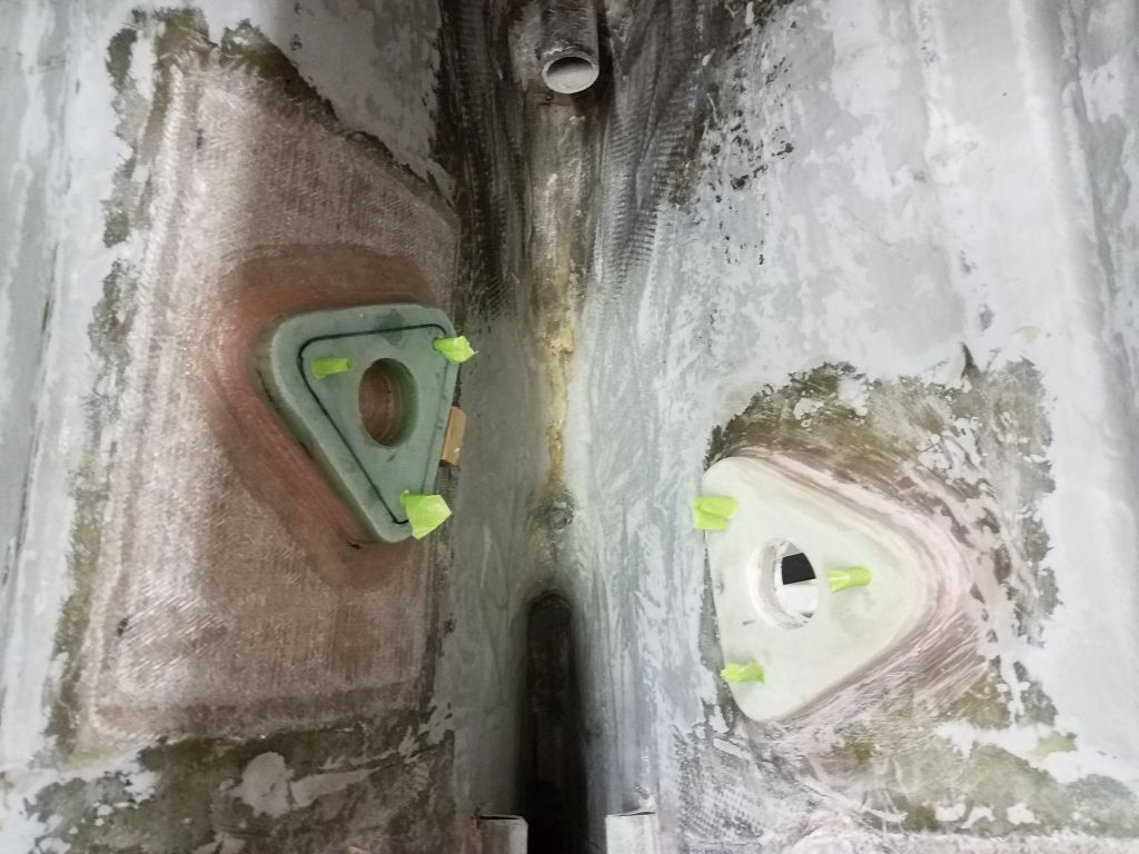
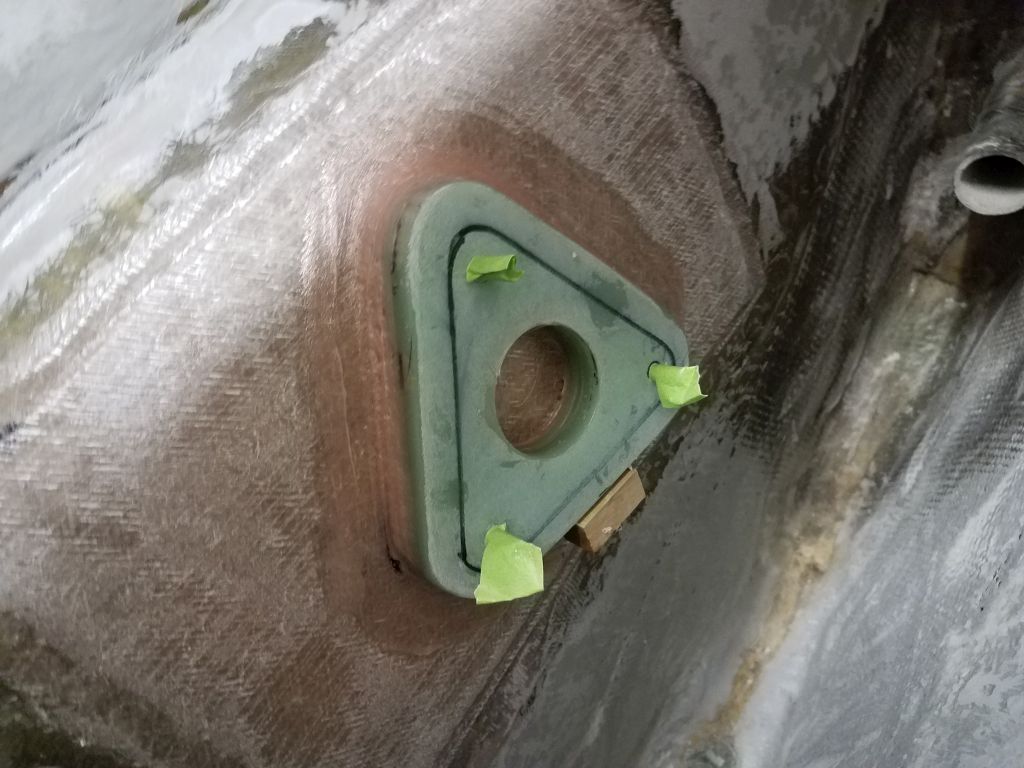
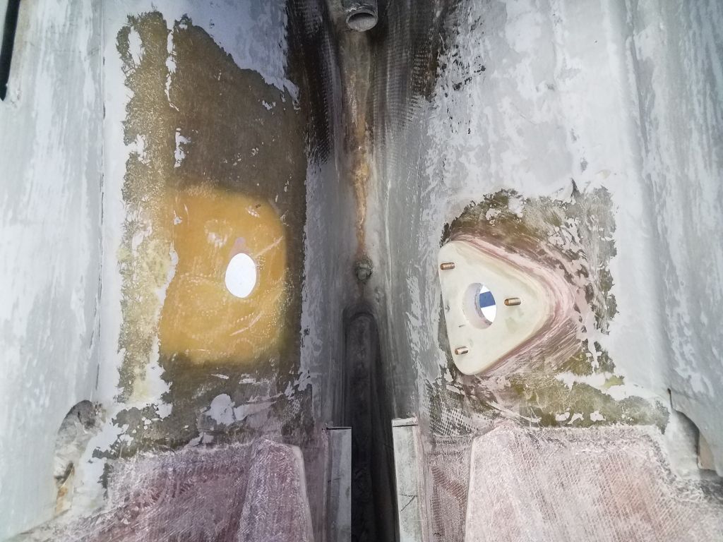
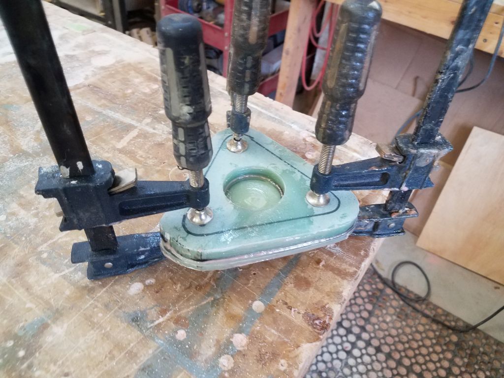
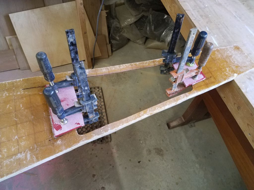
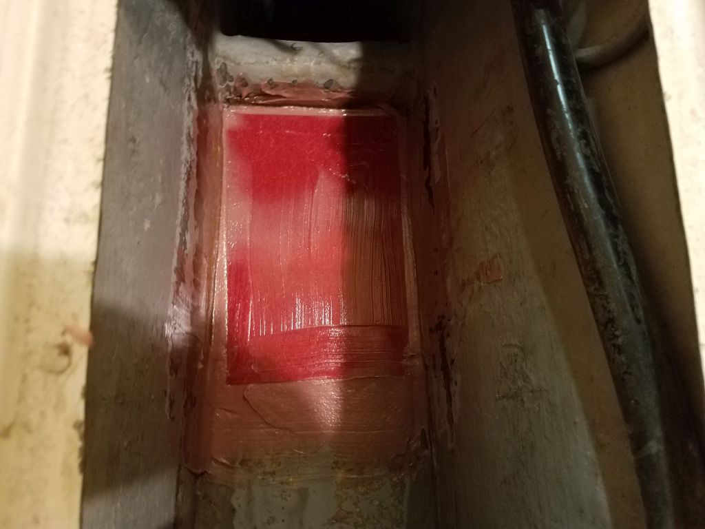
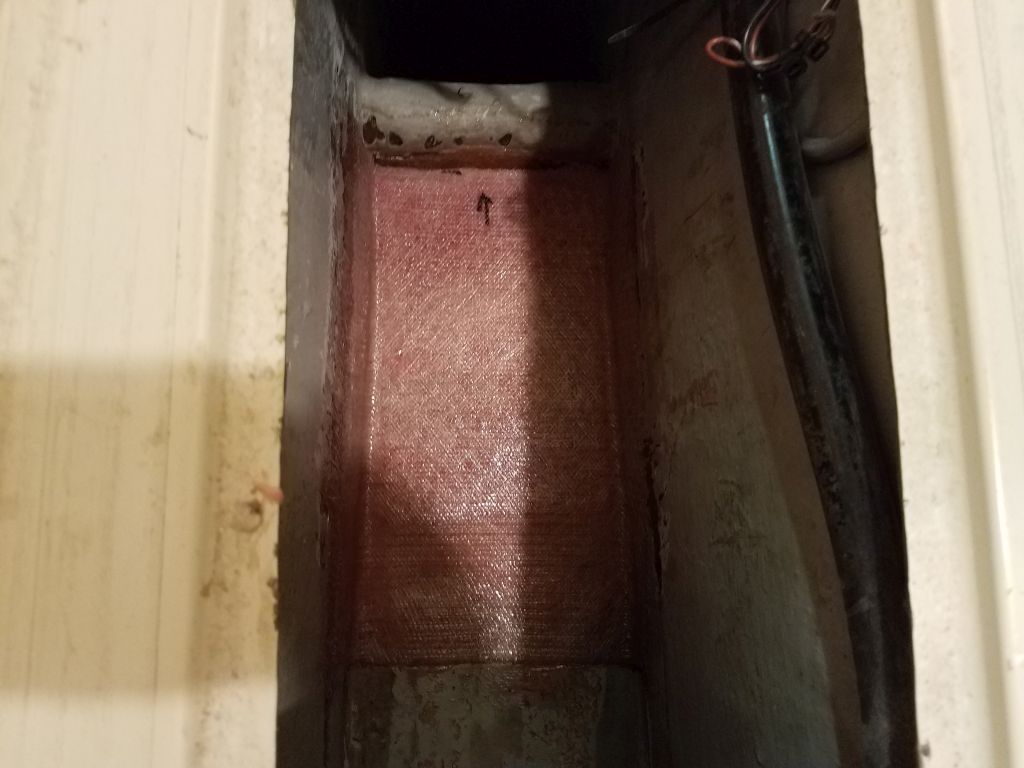
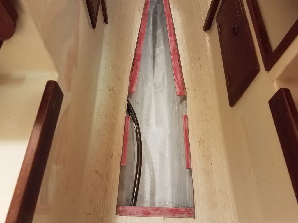
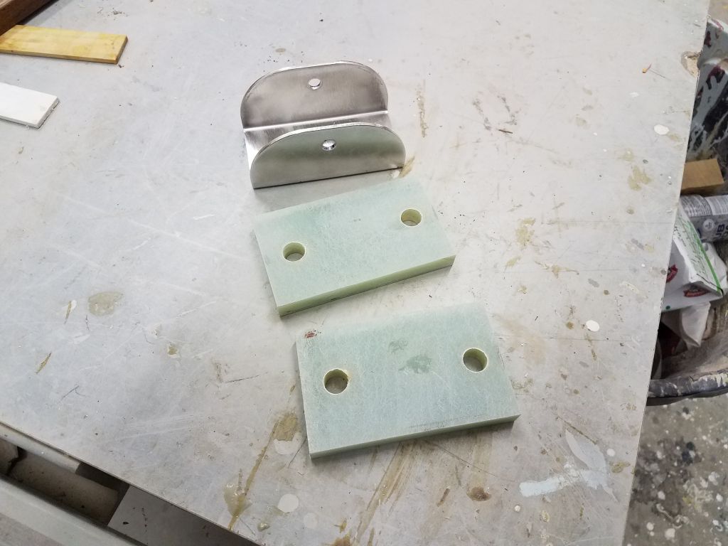
Finally, I prepared two fiberglass backing plates for the deck mounts.  The instructions suggested that no backing plates were needed for the installation, but with these deck fittings (rather than the all-transom mounts found on many installation) and the way the vane ended up being  supported in this case, I felt better using a strong backing plate.

Total time billed on this job today:  8.25 hours

0600 Weather Observation:  10°, clear.  Forecast for the day:  Sun and wind, 20s

Dharma Rose 24

Friday

I removed the temporary glue block securing the galley sink through hull pad, and cleaned up around the pad a bit, lightly sanding as needed to remove any sharp bits inside and out.  Afterwards, I dry-fit the flange base, temporarily securing it with nuts to the stuffs, and from outside threaded in the through hull fitting to check the fit and to see if I’d need to cut the fitting at all for a tight fit (no).

With the tight space in which to work, for this fitting I decided to pre-assemble the through hull valve, flange, and hose fitting to streamline installation, so down on the bench I tightly threaded together the pieces with pipe dope.

After final preparations, I permanently installed the seacock from inside with some polyurethane sealant on the mating surface, securing it hand tight (for now) with the fixing nuts.  Outside, I started the threads of the through hull, then added lots of the sealant to the through hull neck and flange before securing it tightly with my through hull tool.  Back inside, I tightened the fixing nuts, securing the flange tightly, then checked from outside to ensure that I’d tightened the through hull as much as possible; with the tighter nuts inside, I was able to get a fraction of a turn more from outside.

Afterwards, I cleaned up all the excess sealant.

Back at the bench, I assembled the valves and hose fittings for the cockpit scupper through hulls, then installed these to the pre-installed flange bases in the boat, adjusting the rotation of each fitting to ensure that the valve handles cleared each other and the eventual hoses.  I planned to leave the new hoses off till somewhat later, to give me ample room for the engine installation, shafting install,  and exhaust system.

I brought the new ship’s batteries aboard and tested the fit in the battery locker beneath the cockpit sole, and also ensured that my new battery cables would reach all terminals appropriately (they did).  I made up jumpers to connect the two banks, but for now didn’t install any of the wiring since I still needed to secure the batteries.  I ordered some straps for this purpose.

I planned soon to begin the installation of the new Monitor windvane, so I unpacked the box containing it and its component parts so I could check the included inventory and ensure that everything I needed was there.

The windvane came with a stern light pre-wired through the tubing, but not installed to its welded bracket, so I took care of that now.

To finish off the chainplates on deck, I made up a series of cover plates from 1/4″ fiberglass, cutting slots to allow the plates to fit over the chainplates.  On this boat, there was enough room between the bulwarks and the chainplates to allow the covers to slip over the top; on a previous version of this boat I’d had to leave the slots open from the end for clearance.

After checking the fit on each chainplate, and marking accordingly, I eased all the edges of the rectangular plates, and rounded the corners, before applying a coat of spray primer to begin the finishing process.

With some other minor odds and ends and consulting with the rigger who arrived to take away the rigging for replacement, I wrapped up the day and the short week.

Total time billed on this job today:  7.25 hours

0600 Weather Observation:  20°, clouds.  Forecast for the day:  Sun and wind, low 30s

Dharma Rose 23

Thursday

I spent most of the morning working on the galley sink through hull, which the owner had recently asked me to replace.  The original fitting was the usual ball valve-on-a-stalk.

Access within the locker was tight, but I almost got the ball valve to unthread on its own, which I always try first:  it jammed after half a turn, at which point I abandoned my attempt to remove the fittings this way and instead ground off the mushroom head from outside and removed the fitting easily from there.  Afterwards, I sanded the hull outside and inside the locker to prepare the surfaces for new work.

From 3/4″ G-10 fiberglass, I prepared  a backing pad to fit, and went through the various steps to prepare it and the flange base for installation, much as I’d done for the cockpit scupper through hulls earlier.

I dry-fit the pad in the boat, and glued in a support block beneath it to hold it while the epoxy adhesive cured.  Then, I applied epoxy to the threads and heads of the bolts, tightening them down into the mash, and installed the backing pad in a bed of thickened epoxy, cleaning up all excess inside the hole and around the pad.

Meanwhile, I took a moment to install a zerk fitting on an existing through hull for the engine intake, which the owner had also requested.  The 1/8-27 SS zerk fitting fit in the original drain plug hole.  These fittings were a new and recent addition to this line of ball valves, designed to allow grease application and  help keep the ball from sticking over time (a common issue when the fittings aren’t used regularly).

With new supplies on hand in the afternoon, I could finish up a few tasks, starting with the engine control cables.  While access was still relatively good with the fuel fill hose out of the way, I made up the connections behind the control, switching the gear control cable to the opposite side from before, since this transmission required “pull” for forward.  I left the cable ends in the engine compartment for now and would make the connections to the engine once it was installed.

Now I could  finish up the fuel system with the fuel fill hose.  Similar to the original installation, I used a heavy plastic hose barb-to-pipe elbow to allow the fill line to make the bend into the tank inlet.  The original fitting had used a female threaded end with a threaded male hose barb, but I chose a male threaded end to eliminate an additional fitting and joint.  To allow the hose to fit, I ground off the threads from the end.  The way the fuel hose had to turn and connect to the tank obviated the possibility of using a hose barb elbow in this installation.

Up in no-mans land, out of sight and barely within reach, I secured the top end of the hose to the existing deck fitting with two clamps, and reconnected to the tank the existing ground wire.

With the remains of my battery cable, and newly-supplied lugs, I made up the pair of negative cables from the buss bar in the engine room to the battery compartment, completing the basic new wiring work for the electrical system.

Total time billed on this job today:  7.5 hours

0600 Weather Observation:  26°, light snow.  Forecast for the day:  Snow in the morning, 2-4″.  Clearing later.

Dharma Rose 22

Wednesday

During the holiday break, along with a few odds and ends, I finished up the paint work in the engine room and bilge and locker spaces, applying gray bilge paint to all areas as needed.  With this done, and with ample dry time, it meant that I could get right back to work completing the new installations in these areas, particularly the engine room.

I’d ordered and received new hardware for the cockpit scupper drain replacements, so with the new bronze on hand I got to work installing the new fittings.  During a dry-fit, I found that the molded opening on the port side was a bit smaller than its counterpart to starboard, so the flange of the flush through hull fitting didn’t quite fit, so I ground off a bit on one side to allow the fitting to properly fit in its intended location.

I tested the fixing nuts to ensure I’d have no problem installing them tightly, then removed the fittings and cleaned up the bonding areas, cleaning off old sealant.  Then, I installed both fittings in heavy beads of sealant, securing them tightly with the fixing nuts and cleaning up the excess sealant.

To finish off the installation, I installed 90° hose fittings on the through hull threads.  These fittings featured a flange, gasket, and loose female nut, like a union, so I could install the fittings easily  and position the elbows where I wanted them.  This completed the new installation.  I’d soon finish up the new seacock installation and install the new drain hoses, but for now I kept the after end of the engine room clear pending some additional work.

Now that the engine room was painted, I ran the engine wiring harness through the space beneath the fuel tank and out the opening where the waste hose used to be, leaving it there for eventual connection to the engine once installed.

I installed the new fuel filter in the location I’d prepared earlier, then installed lengths of 5/16″‘ fuel hose for the fuel supply and return lines.  I made up the connections at the fuel tank for both lines, and secured the hoses to the bulkhead in the engine room, leaving a length of excess hose for the final return line connection to the engine.  I tucked the excess behind the fuel filter for now.

During the earlier work in the engine room, to clear the way, I’d removed the discharge hoses for the three bilge pumps (2 electric plus the manual).  Now, it was time to reinstall these hoses while I still had good access.

Next, I turned to the electrical wiring, mainly the engine and battery cables, as the remainder of the existing wiring was outside the scope of my work.  During earlier rounds of work, I’d removed the old wire ties and clamps securing some of the existing wiring in the forward part of the engine room, so my first task was to resecure these wires along the top edge of the space.

To improve the wiring, I planned to install positive and negative cable buss bars in the engine room, which would serve as the distribution points for the remaining cabling and some of the existing wiring.  The port bulkhead was clear and convenient for this use.  Covers for these buss bars were backordered, so for now I went ahead with the installation so I could finish up the wiring; I’d install the covers once they arrived.

I started with short lengths of red (positive) and yellow (negative) cable to connect to the engine itself.  Since access would be much tighter once the engine was in its space, I chose to pre-install these short cables now, which was easy with good access to the side of the engine now.  With the main distribution busses close to the engine’s final location, these cables could be quite short, and final connection would be straightforward..

During the remainder of the day, I made up various lengths of battery cabling, starting with the positive cables so I could reassemble the battery switch and connect some of the existing wiring.  I led the cabling down the hull along the forward end of the engine room, then forward to the battery compartment, leaving ample slack for final connections to the batteries.  I loosely made up the connections to the new buss bars as available, though I’d need to remove these later so I could install the protective covers.  I ran out of the lugs for the battery cables, so I’d have to finish up the negative cabling once the new parts arrived.

Total time billed on this job today:  10.5 hours (including miscellany during the break)

0600 Weather Observation:  18°, mainly clear.  Forecast for the day:  Sunny, 20s

Dharma Rose 21

Friday

Overnight, the cockpit drain channel, which I’d filled with water, leaked out through the port scupper fitting in the deck, leaving water only in the fittings and confirming what I’d already determined shortly after adding the water.

With access as good as it would ever be, now was the time to deal with the problem, and I made several attempts to loosen the fixing nut beneath the port drain fitting.  The fitting was nearly touching the nearby bulkhead leading to the port cockpit locker, and the nut was quite tight, and possibly secured with sealant as well, and after trying various tools to loosen the nut, I couldn’t make any progress, since wrenches interfered with the bulkhead when I tried to grip the various faces of the nut, or if I tried other faces the wrench would hit the other side of the engine room.

After a discussion of the situation, the owner chose to remove both fittings through whatever means and replace both, so after a false start with a grinder and cutoff wheel–I couldn’t manipulate it into the correct position in the oddly accessible-yet-impossible-to-access area beneath the cockpit, so I switched to a reciprocating saw with a long blade, which allowed me to cut through the drain fittings just flush with the tops of the nuts, after which removal was straightforward.

I ordered replacement scupper fittings that I hoped would work (they might be too large), and moved on.

After quickly and lightly sanding the newly-fiberglass engine pan, I worked on the fuel tank to resecure it to its platform with the original strap and a screw at the after edge.  Then, I reinstalled the various hardware, from the fuel gauge to the supply and return fittings, all of which were in good condition, though I replaced the hose nipple for the return line because it was simpler than trying to salvage the old with the hose still firmly attached.   The black coil on the top of the fuel tank is the engine wiring harness, also awaiting engine room paint and the engine installation itself.

I found that the plastic elbow incorporated in the old fill hose was cracked, so I waited on finishing up the new fill line till I could source a suitable replacement; I’d install fuel supply and return hoses as soon as the engine room was ready after paint.

In the port cockpit locker, I removed the remnants of the old vented loop from the original engine exhaust system, retaining the line that led from the loop aft to the exhaust gooseneck at the transom.

The new engine would require a 1″ vented loop, which the owner had ordered along with the engine, and now I installed the fitting in the locker, removing the vent valve from the top and replacing it with a hose fitting and the discharge line leading aft.  I drilled larger holes to accommodate the new 1″ hoses from  the engine room, replacing the smaller holes that had been there for the old system.  Once the engine was in place, I’d run the hoses from the exhaust elbow.

With the pre-engine work about as far along as I could bring it for the moment, I turned to the chainplates, which were ready for reinstallation.  I’d felt lucky to have been able to remove the bolts from the centermost chainplates on each side without removing the boat’s bulkheads, which I’d had to do on two sisterships in earlier projects, and now I hoped I could reinstall nuts and washers in the tight spaces successfully:  It’s one thing to remove stuff in tight quarters, but often quite another thing to do an installation.

Starting with the hardest chainplates–the center one on each side–I was happy to find that while the installation space was tight, it was possible to get the washers and nuts on in the 1″ or less space between the knees and the bulkheads.  On the port side, I could even put the nuts on by hand in the lavishly expansive space, but to starboard I had to tape the nuts into the open end of my 7/16″ wrench in order to get the started.

The remaining two pairs of chainplates had good access, and reinstallation was simple.  Later, I’d finish the installation from above with bedding and new deck covers to help seal the slots through the deck.

To finish up the day and the week, I made final preparations in the engine room–cleanup and some minor masking–and applied a coat of epoxy-based 2-part primer over all the fresh epoxy work in the space, along with the base of the battery compartment beneath the cabin sole.  This would help seal the new epoxy and allow me to finish up the paint work in the near future, which would pave the way for final engine and related systems installations.

Total time billed on this job today:  6.25 hours

0600 Weather Observation:  40°, light rain.  Forecast for the day:  Heavy rain, rising into the 50s


Dharma Rose 20

Thursday

With some other commitments away from the shop, it was a short day, with just a few hours available, so I continued to pick away at my pre-installation list for the engine.  I planned to start to reassemble the fuel tank, but realized to be safe I should first run in the wiring harness assembly for the engine panel, which had to go through a tight space behind the fuel tank in order to run forward to the panel location in the cabin (which was the same location as the original engine panel).

To begin, I used a template for the engine panel cutout to enlarge the opening left behind from the original panel.

The plugs on the wiring harness were almost too large to fit through the opening running from the starboard cockpit locker (behind the fuel tank) and the cabin/interior liner, and in fact when I tried to pull the harness through from the cabin to the locker with a snake, the engine end of the cable wouldn’t fit through the opening.  I tried running the cable the other way, pushing the smaller panel plug end through from the cockpit locker, and this worked, though not without a micron to spare.  From there, it was a simple matter to connect the panel and install it with four black-coated stainless screws.  I left the remaining wiring harness loose in the cockpit locker for now, pending engine room paint.

The owner and I had had a few discussions about the new engine drip pan and its potential removability, and eventually he decided he preferred the idea of making the pan permanent, more like the original, so to ensure I could keep moving forward on my plan to prime and paint the engine room before Christmas break, I worked on this for the brief remainder of the afternoon.

After cleaning up the area with a solvent wash, I installed the new pan, which was all ready in any event, and added nice epoxy fillets along the sides and up the ends.

While the fillets cured for a while, I prepared and cut two layers of fiberglass to tab over the pan and up the hull on each side, and added additional fiberglass to wrap up the ends of the pan.  Once everything was ready, I wet out and installed the new fiberglass in epoxy.

The owner also mentioned that one or both of the scupper drain fittings in the cockpit had appeared to leak.  Of course removal and rebedding of these fittings might not be as straightforward as one would hope, since the elbow fittings beneath the cockpit were installed before the deck was placed on the boat, so there was no room to spin these or any other elbows off the through hull threads.  Hoping to avoid the need to rebed,we decided to check first to see if the fitting (s) did leak.   I used a length of old hose to connect the two drains belowdecks, an easy way to plug them, and plugged the cockpit supper wells with butyl sealant so I could pour in some water to the channel and allow it to sit, and see if any leaks appeared.

Unfortunately, before the end of business I noticed that the port fitting indeed had a slow leak into the engine room, so I’d make a plan to rebed it soon.  With luck, I could unscrew the fitting sufficiently to rebed without having to completely remove it and the elbow fitting.

Total time billed on this job today:  3 hours

0600 Weather Observation:  10°, clear.  Forecast for the day:  Sunny, 40s

Dharma Rose 19

Wednesday

Now the starboard through hull pad was back to where I started earlier in the week, so it was time to move forward with the through hull installation.  After lightly sanding the new fillet, I drilled the hole through the hull, using the backing pad for alignment.

To begin, I dry-fit the flange bases and the rest of the hardware to ensure the proper fit inside–which was all good this time.  The valves and hose nipples would easily spin and and off without interfering with each other post-installation, so I didn’t have to worry about having all the hardware in place while I installed the critical bases.  During final installation, I’d align the valve handles so that both would operate fully without interference, unlike how they’re shown here.

From outside, I threaded in the through hull fittings as far as they’d go, till they bottomed out in the flange base above, and then marked the threads where they entered the hull so I could cut off an appropriate length of threads.

I transferred the measurements generously to the top ends of the through hulls and cut off the excess with a grinder, cleaning up the threads using the original through hull nuts.  This meant that now I could thread the through hulls in tightly from outside.

Satisfied with the fit, I disassembled everything and proceeded with the final installation.  Starting inside, I applied polyurethane sealant to the tops of the pads, and installed the flange bases hand-tight with the nuts to secure them.  Then, outside, I gooped up the through hull necks and heads heavily with the sealant and threaded them in tightly using a through hull tool, creating lavish squeezeout.  The starboard side gave me some fits when I had trouble starting the threads, but eventually I prevailed.

Inside once more, I added lockwashers to all the mounting studs and tightened the nuts securely, and cleaned up any excess sealant squeezeout inside and out.  I’d wait to install the valves and other hardware till after I’d painted the engine room in the near future.

Later, I continued work on my final pre-engine install list, starting with the raw water filter that I’d removed earlier in the project.    To improve access for inspection and maintenance, at the owner’s request I added a simple screw-in deck place in the berth top above the filter location, which would greatly ease future connections and basic maintenance of the filter.  I changed the fittings on the filter to a larger 3/4″ size to accommodate the new hose (along with a new 3/4″ hose connector on the nearby through hull), and reinstalled the filter to the bulkhead as it had been when the boat arrived.  I’d do the hose runs later, once the engine was in place.

I located the new fuel filter at the forward end of the engine room, leaving ample room for servicing both ends of the filter.  This was a temporary installation only, as final installation would wait till I painted the engine room.

The old engine control cables were still in place, and I planned to replace them with new.  In addition, I’d need to change the gear lever position to accommodate the way the transmission lever on the new engine operated, so now I removed the two cables while access was as good as it could ever be in the tight space aft of the still-adrift fuel tank.  The control unit itself was in good condition, and I’d install new cables as soon as I could get measurements for their lengths.

Total time billed on this job today:  6.5 hours

0600 Weather Observation:  12°, mostly clear.  Forecast for the day:  Sunny, low 30s

Dharma Rose 18

Tuesday

With the engine still in place on the foundations after resting overnight, I made some final reference marks to determine where I needed additional cuts, mainly at the port aft end to improve clearance for the transmission shift lever.  Then, I removed the engine so I could make the cuts, before lowering the engine once again and repositioning it on the foundations.

The new cut at the aft end helped, but I found that I’d need to open up the cutout a bit at the forward end to allow full operation of the lever, so I noted the changes .  For now, the engine was sitting properly enough on the foundations that I could move on with some of the immediately-related work that I wanted to accomplish now.

Part of the engine block came within a whisker of contacting the edge of the foundations just aft of the forward mounts, so I made some marks there so I could slightly open the area later, once I’d removed the engine again.

Using the stand-in propeller shaft as a guide, I joggled the engine around a bit to get it positioned generally in the right spot so that the shaft lined up with the center of the transmission coupling.

To get a better sense of the rough engine alignment, as well as measure the final length of the propeller shaft, I temporarily installed the shaft coupling on the end of the fiberglass shaft, which required a bit of sanding so it would fit.  With the coupling in place and the shaft back in the boat, I lined it up with the transmission, and while the initial line-up was pretty good, the coupling faces were slightly off on one side, so I made some adjustments to the engine’s transverse and longitudinal positions, and slightly to the height of the aft mounts, which brought the coupling faces more tightly together, good enough that I felt like I could start to mark the shaft length, as well as the engine mount locations on the foundation.

After double-checking the shaft position in the coupling, and ensuring that the coupling was properly placed vis-a-vis the transmission coupling, I went outside to mark the shaft where it exited the Cutless bearing, and used my notes from the original setup to mark the end of the shaft 4-1/2″ aft of the stern tube, leaving about 1″ clearance forward of the rudder, as before.

Now I could remove the shaft and make the final measurements so I could order the new shaft soon.  The actual shaft length in this form came to 37-7/8″, and I’d need to make an allowance for the thickness of the flexible coupling that I’d install between the shaft and transmission couplings during the final installation.  I held the old shaft against the new mockup just as a reality check; if something was far off, I’d check the measurements again.  As expected, though, the lengths were close, but slightly different thanks to different engine lengths and positions.

This completed the initial round of engine fitting, and I removed the engine back down to the shop floor for storage till I was ready for the final installation.

Next, I used sanders to clean up and smooth over the various cuts I’d made in the engine foundations and around the engine hatch, and to further massage the cuts around the transmission lever, where I’d made additional marks to enlarge the cutout.  I used a small drill bit just to mark the centers of the engine mount holes that I’d marked, so that these locations would survive through the final engine room painting.  I didn’t want to drill the final bolt holes till I was positive of the engine position later.

While I was at it, I lightly sanded the patches (inside and out) over the starboard scupper through hull, as well as the new floor in the battery compartment in the cabin.

Meanwhile, inside the boat I unclamped the cabin sole and cleaned up all the masking tape, completing the work there for all intents and purposes.  

After cleaning up from the past couple days’ work in the engine room, I moved on with the through hull backing pad replacement.  After cleaning up the new pad, I laid out, drilled, and tapped the fastener holes for the mounting bolts from the underside of the pad, just as I’d done originally.

In the boat, I temporarily installed the port flange and valve, then, with the starboard side dry-assembled on the new pad, checked for clearance between the two valves and marked the hull accordingly for the new starboard pad.  Meanwhile, I applied a layer of fairing compound over the outside of the patch.  I’d wait to drill the new hole through the hull till the new pad was installed.

To install the new pad, I first loosened the three bronze bolts a bit, and added epoxy adhesive to the base of the threads to help hold them permanently in place.  Up in the boat, I installed a support block with hot glue, which would help hold the pad in place on the near-vertical hull, then installed the G-10 pad in thickened epoxy.  I left the new pad to cure overnight.

Total time billed on this job today:  5.25 hours (plus 1.25 hours not billed for the through hull rebuild)

0600 Weather Observation:  21°, cloudy.  Forecast for the day:  Slow clearing, windy, highs in the 20s

Dharma Rose 17

Monday

Over the weekend, I painted the new bilge area (formerly the waste tank) with gray bilge paint, completing the work within.

This meant that I could move forward to install the cabin sole, starting with a final test-fit.  Then, I made final preparations, including cleaning the bonding surfaces and masking off the edges of the opening, as well as the center section of the sole, to protect these from epoxy.  Finally, I installed the sole in a bed of thickened epoxy adhesive, clamping it well wherever possible and adding weights at the ends to help secure those areas I couldn’t directly clamp.  I filled the gap at the cut line with additional thickened epoxy as well.

While the sole adhesive was curing, I planned to spend the day in the engine room, starting with the scupper through hulls, which I was ready to install as I began to close in on the final work leading up to the engine installation itself.  I gathered the various pieces of each  through hull assembly, and prepared to go through the normal motions of through hull installation.

Inside the boat, I dry-fit the two flange bases on the pre-installed backing blocks and studs, intending to test-fit the threaded through hulls themselves and cut them to length.  First, though, I wanted to see if I’d be able to spin on the through hull valves after installing the flange base and through hull, or if I needed to pre-install the valves first, given the tight confines of the space and proximity of the two fittings across from one another.

Immediately, this highlighted a major problem:  The two valves didn’t clear one another sufficiently.  Well, the valves sort of did, but there was no way that the pipe-hose nipples would clear enough to allow a workable result.

I felt like kicking myself off the boat.  I knew the two locations were close, of course, but also knew they were slightly offset, intentionally, and that the old valves had fit.  But none of that mattered here, since in this case the two fittings interfered with one another in an ultimately catastrophic way. 

I should have checked before starting the install long ago whether the new fittings would clear one another, but I never had.  I foolishly assumed, without confirmation, that the new fittings would fit in the same locations.

Contemplating this unwanted turn of events, I considered my options.  First, of course, was to move one of the fittings.  Over the years, as I’d installed things like this, I’d often wondered what someone, say, 30 years in the future might have to say about my installation, and how difficult these installations might be to remove.  I never had any problem with the apparent permanence of what I considered a permanent installation, like a through hull, so had never worried about providing for its removal.  Now it looked like I might get a chance to try.

I really, really did not want to have to do that, so I considered if there was an alternative.  I thought of changing the hardware to 1-1/4″ valves, which would work with a full-flow tailpiece to accept 1-1/2″ hose and which I’d sometimes used in the past because the slightly reduced flow diameter of the 1-1/4″ valve meant the valve body itself was substantially smaller.  I thought that this might improve the clearance here enough to work, and was all set to order the new parts, but then I realized that the bolt pattern of the smaller flange base would also be smaller, and since I’d pre-installed the bolts in this case, there was no way to change the hardware either.  

This left me no option but to get on with it and remove one of the new pads I’d installed, and reposition the through hull sufficiently to allow the required clearance with the other side.

I chose the starboard side because it was positioned aft of the port fitting, and there was room to move it a bit aft; the port side would have had to move forward to increase clearance, and this would have brought it unnecessarily close to the engine foundations.

With grinder and cutoff wheel, and a reciprocating saw, I removed the “old” base as well as I could.  Access was, of course, difficult, between the tightness of the space (shoulder room), the steep curvature of the hull, and the proximity of the nearby longitudinal bulkhead, but with significant effort I got through the G-10, leaving just remnants of the epoxy adhesive that I could grind smooth once more.  I extended the ground area a bit aft to provide space for the necessary patch (to fill the old hole) and also for the new location.

With the miserable work in the engine room completed, I moved outside to prepare the exterior of the hole for patching in the usual way.

To patch the old hole, I masked over the opening from outside, then filled the hole with reinforced, thickened epoxy from inside, using some leftover epoxy to wet out the newly-ground area inside and make it ready for two layers of fiberglass over the whole area, including the after section where I planned to install the fitting when the repair was complete.

Meanwhile, I turned to building a replacement pad for the flange base.  Of course I found that my remaining supply of 3/4″ G-10 wasn’t wide enough to accommodate the size of the flange properly, so I had to make up a lamination from a piece of 1/2″ and 1/4″ G-10 to provide the requisite thickness.

A bit later in the day, the epoxy had cured enough to allow me to remove the masking tape from the outside and install three layers of fiberglass over the exterior, completing the basics of the original hole repair and getting me closer to starting the new re-installation.

Removing the old pad, patching the hull, and the other work took two hours, which I expunged from the day’s totals, and I suppose it all could have been a lot worse, though it was an exercise I didn’t plan to do again anytime soon.  Still ahead I’d need to reinstall the new G-10 base and relocate the through-hull hole, which would catch me up with where I’d started at the beginning of the day.

Moving on, I cleaned up the glue joints on the fiberglass drip pan assembly, and after a final test fit drilled and tapped for four screws that would eventually secure it to the cleats in the boat.  I’d finish up all the painting in the space before I installed it permanently, however.

Next, I thought I’d test-fit the engine in the compartment.  I anticipated a need to slightly modify the deck opening, as well as possibly some modification to the engine foundations to fit the engine, and in neither way was I disappointed.

When I installed the flexible mounts on the engine after I had it up in the cockpit, I immediately noticed a potential clearance issue with the port after mount, which barely cleared the transmission lever at best, and not at all if the mounting base had to angle, which I thought it probably would in this installation.  This issue came to light because of the narrow 11-1/2″ mounting centers, for which the engine wasn’t really designed.  Whether this became a real issue or not would depend on the final height of the mount versus the protruding bolt on the transmission lever.  Right now, they were nearly level with one another, and I expected this was something I’d have to deal with, but first things first.

With the engine suspended over the opening, I noted where cuts were required to expand the opening for an easier fit for the engine, then made these cuts as required.  I’d come back later and clean up the cuts with a sander, but for now my goal was (at first) to set the engine in the boat so I could measure for and order the new propeller shaft, so I left the fancier work for later.

Making the cuts was slow going, as there were heavy layers of fiberglass plus an aluminum plate in the engine compartment surround.  I left all the existing bolt holes (which threaded into the aluminum plate) intact for reinstalling the cockpit sole/engine room cover later.  Once I enlarged the opening, lowering the engine posed no problems.

There were several clearance issues that immediately prevented the engine from lowering all the way to the foundations.  First, the oil pump hose, which ran out the starboard side of the engine from the oil sump and which frequently causes minor issues in tight installations in my experience, hit hard against the foundation (which angled inwards as it ran aft thanks to the requirements of the hull), so I made some marks there to cut out a section of the foundation and allow clearance.

Raising the engine out again, I cut out a chunk of the foundation in way of the oil hose, and lowered in the engine again.

Now there were several other clearance issues, all of which caused by the tight shape of the hull and narrowness of the foundations at the aft end.  There were places where the bell housing at the after end of the engine contacted the edge of the foundations, so I marked these as needed.  Also, there would be a need to cut out a large section at the very aft side to port, to allow the transmission lever clearance to operate (i.e. to be pushed down).  I made reference marks for that, but at least for now I could leave it be since it wasn’t preventing the engine from sitting where it needed to.

The oil hose now fit fairly well, but to avoid chafe I needed to open up the cutout just a bit more.

Meanwhile, I could check the basic engine alignment with a 1″ fiberglass tube that I used as a stand-in for the shaft.  Some continuing adjustments would be required to shift the engine slightly to port, but otherwise things looked pretty good.  Some of this adjustment would be possible once I’d made the newest clearance cuts in the foundation, so I lifted out the engine once more.

After finishing the new cuts, I lowered the engine in once more, and things were looking better and closer to where they needed to be.  But the clearance issues on the port side continued, not only the transmission lever (which I’d yet to cut out), but with that after port mount, which was likely to be an issue with the transmission, as well as with the curvature of the hull, which right now was preventing the engine from moving in the correct and required direction.

I let things stand there for now.  Though I had the engine nearly as far forward as it could go (the further forward, the better the clearances at the aft end), I thought I might be able to go just a bit further forward.  In any event, the day was done, and it was time to go clean up from the day’s snowstorm.

Total time billed on this job today:  5.5 hours (plus 2 hours not billed for the through hull re-work)

0600 Weather Observation:  32°, light snow, about 2″ down.  Forecast for the day:  Snow, a couple more inches, 32°

Dharma Rose 16

Friday

After additional research into alternatives, and a conference with the owner, we decided that, barring unforeseen circumstances, we would keep the existing fuel tank, which would save the additional work required to remove it.  Since the tank appeared to be in good condition, this seemed a realistic choice.

With this decision made, I strove to document the condition of the hidden areas of the tank as much as possible, just to be sure there wasn’t some unpleasant secret lurking beneath the tank.  I could move the tank about in the locker a fair bit, and was able to angle it in such a way as to get a number of photos blindly of the bottom and outboard side of the tank.  Without fanfare, here they all are.  These show no signs of worrisome problems and confirm the general impressions that the tank has substantial life remaining.

To gain better access inside the tank for further inspection and cleaning out, I removed the fuel gauge.

There were several ounces of fuel still in the tank that I’d not been able to remove, and I tried once again with my little primer bulb-based siphon/pump hose that I use, but I was unable to pump the fuel for whatever reason.    Later in the day, I had to run an errand for an unrelated task, and while I was out I found a little battery-operated pump with a rigid suction end that fit perfectly (and just barely) through the fill neck, and worked a charm to pull out the remaining fuel from the tank.  This also pulled out most of the minor debris that was in the fuel (all normal for a diesel tank), and by sloshing the fuel beforehand I’d confined all the debris to the low side for removal.  Afterwards, I was able to stuff in a couple rags and move them about to remove the last remnants of fuel and old debris, leaving a nice clean tank.

For now, I left the fittings off and the tank loose in the compartment, as I had some additional work to do in there where it’d be helpful to move the tank around for access.  I covered the openings with a rag for now.

I removed all the clamps from the new cleats at the cabin sole, and with the way clear I test-fit the sole piece, and made reference marks for the two end supports I wanted to install for the new forward hatch opening.  Back on the bench, I cut and installed more 1/4″ fiberglass cleats in epoxy.

I installed the new Cutless bearing after inspecting the stern tube and surrounding area.  With the bearing dry-fit, I marked the location of the two setscrews, then removed the bearing and used a drill to just score the brass surface at those marks, the better to accept the set screw points.  Then, I installed the bearing for real, securing the setscrews with a dab of sealant and covering over the heads with more sealant.

As a final check before I continued work in the engine room, all geared towards getting the engine in place in the near future, I set up the alignment string once more and adjusted the template and the feet to fit properly on the new foundations.

The owner mentioned off-handedly that he didn’t care for the old access port leading to the now-abandoned little section of the old waste tank beneath the battery platform, and, no time like the present, I went ahead and removed the inspection port, prepared the area, and installed a new 1/8″ fiberglass platform over the old hole, securing it with epoxy adhesive and a layer of fiberglass over the whole thing and up the sides of the compartment.

To round out the day, I applied a quick coat of epoxy-based primer over the new fiberglass in the bilge/waste tank area.  For unknown reasons, many paints won’t cure properly over new epoxy resin, and rather than wait some indeterminate length of time for the epoxy to fully cure, I now use this 2-part tie coat to prepare the surface for painting with bilge paint immediately.  I also applied the primer over the patches in the forward part of the boat (old waste through hulls and tank entry point).

Total time billed on this job today:  6.5 hours

0600 Weather Observation:  18°, clear.  Forecast for the day:  Mostly cloudy, 30s

Older posts Newer posts