(page 1 of 4)

Dharma Rose 35

Thursday

With the end of the project, the owner arranged to have the boat surveyed for his insurance purposes, and once that was over with early in the week, I went ahead to prepare the boat for her imminent departure, restowing and securing the mast on deck and loading various gear back aboard.

One final detail remained.  I had hoped to be able to install a zinc on the prop shaft; while in my mind the requirement or even desirability of this remains in question, at least when the boat’s underwater metallic compontnents are electrically isolated from one another (as they are here), there seemed little down side other than simply recycling zinc through the ecosystem.  The first prop hub zinc I’d tried, a standard and readily-available version, didn’t fit in the tight space between the prop and the rudder on this boat, but after a pretty extensive search I found a version that looked promising and ordered it.

When the new zinc and nut assembly arrived, and after quickly determining that it would work here, I installed it.  This zinc came with a prop nut that replaces the original two nuts, so I removed those and installed the supplied prop nut tightly.  The zinc itself is designed to fit over this nut, with a hex-shaped recess on one side, and then the zinc is secured with a castle nut at the end of the shaft, which fits inside the rounded aft end of the zinc.  I finished off the installation with a cotter pin to hold the arrangement in place.

With a brief unusually-warm weather window (if not fair weather), the owner planned to pick the boat up and bring her home in a whirlwind trip, and I got the new zinc in place just in time before the owner arrived in Maine in the evening.

in the morning, with freakishly warm temperatures but a newly-icy and slick (but aesthetically reflective) driveway thanks to the recent snow now saturated with rain, the owner departed for home with the boat, ready to finish a few small projects and go sailing this summer.

0600 Weather Observation:  40°, rain.  Forecast for the day:  Heavy rain, 50s

Dharma Rose 34

Friday

With the scope of my varnish work complete–2 coats at the owner’s request–I installed the hardware and hinge on the new companionway boards, completing their construction.

Next, I finished up in the interior with some minor reassembly, including the bi-fold head door and two wiring chase covers that the owner had removed earlier but asked me to install now.  I also installed the cabin sole.  Meanwhile, now that work was complete, I finished some of my earlier efforts to clean up the cabin, remove tools, and so forth.

In the engine room, I finished up by adding the basic fluids to the engine:  coolant (both to the heat exchanger and the separate overflow tank); engine oil (about 2 liters); and transmission fluid (about 0.2 liters).

Finally, I installed new vent hoses between the engine room and the after cowl vents, replacing those I’d removed earlier in the project.  I installed the tiller, thus expunging the last item from the project scope.

Total time billed on this job today:  4.75 hours

0600 Weather Observation:  Partly clear, 15°.  Forecast for the day:  Snow shower, mostly cloudy but improving later, 30°

Dharma Rose 33

Thursday

Next on my dwindling agenda was  to install the new shaft, which had recently arrived from the machine shop.  A bench-fit showed that the coupling was too tight a fit, so I cleaned up the inside a bit until I could slip the coupling over the shaft with acceptable ease.  I double-checked the length of the new shaft against my original measurements to ensure it was what I’d asked for (it was).

I slipped the shaft through the stern tube, and from inside the boat installed the packing nut over the end, then installed the split coupling and key, securing it with the shaft setscrew and the two coupling bolts to squeeze the coupling together.  With the coupling installed, but before installing the sacrificial coupling section, I completed the final engine alignment, adjusting the mounts as needed to bring the transmission and shaft couplings into alignment.  Once aligned, I tightened all the mounting studs and bolts to affix the engine permanently.

Now I moved the shaft back a bit to make space, and completed the installation with the sacrificial plastic coupling, which bolted between the shaft and transmission couplings to provide electrical isolation, a bit of alignment forgiveness, and as a failsafe to help prevent damage to the transmission should the propeller hit an immobile object.

I completed the installation with the new propeller.  This is a  Campbell Sailer size 11×6.

I tried the fit of a prop nut zinc assembly, but unfortunately there wasn’t enough clearance in the tight aperture even for the nut itself.

As a final step, I tightened down the stuffing box nut, tightening it more than would ultimately be necessary so that upon launching, there’d be no unexpected nor unwelcome surprises from the stuffing box; it would require proper adjustment at that time, however.

Total time billed on this job today:  3.75 hours

0600 Weather Observation:  6°, clear.  Forecast for the day:  Sunny, 16°

Dharma Rose 32

Wednesday

To finish up the new companionway boards, I used the old top board as a guide to measure for and lay out the location for a new ring pull on the new piece, then, with a router, chisel, and large drill bits, relieved the opening as needed to accommodate the flush ring pull.

To match the original, I milled a small piece of solid teak for the back side, creating a small handle.  I attached this with glue and temporary screws through the front side, which holes would later accommodate two longer screws to secure the new ring pull.

The owner requested that I apply a second coat of varnish to the new boards, so now I did so.

Meanwhile, I reassembled the original set of boards with their original hardware.

The owner had brought me a new, slightly-oversized teak cockpit grate blank, and requested that I fit it as needed.  I had the old grate on hand as well, but to use it as a template I first had to remove some cleats from the bottom side so I could lay it flush on the new grate for marking and trimming.  I found that the new grate was a close fit, but one long side required a  slight trim, and I also had to open up a relief cut (for the cockpit gear lever) at the starboard aft end.

With the cuts completed, I tested the fit, which matched the original as expected.

The cockpit sole, with its removable engine hatch  and short fixed aft section, was not quite all at one level, which is why the cleats had originally been added to the old grate.  After checking the fit of the new grate, I decided I could simplify the cleat system, since the after section was just 3/8″ lower than the forward section, so I milled some cleats of appropriate size and installed them with screws.  Later, I’d need to slightly relieve the forward portion here and there to accommodate the screw heads that secure the engine hatch in place, since the grate by requirement sat directly above many of these screws, but the old cleat system hadn’t eliminated this need either and had required the same relief cuts.

The rigger was on hand  during the morning to install and complete the new standing rigging, which included mechanical bottom terminals which, because of the way the rigging passed through holes in the mast, had to be installed on site.

I was away from the shop for a while on other business, but upon my return I decided to finish up the chainplates by trimming the excess sealant from around the new deck covers.

Total time billed on this job today:  4.75 hours

0600 Weather Observation:  26°, cloudy.  Forecast for the day:  Mostly cloudy, snow shower, 37°

Dharma Rose 31

Tuesday

Finishing up the hose runs and installations in the engine room, I installed the new hoses for the cockpit scuppers.

When I’d first installed the batteries a few days earlier, I found that the little fuses (I’d had them in stock) I’d installed on the positive terminals were already blown, causes unknown, but it gave me a moment’s consternation when I turned the battery switch and nothing happened.  Since the only wiring I’d done was on the battery and engine side, I’d no idea as to the status of the boat’s existing wiring, though I knew from the owner it was functional.  Brief troubleshooting at the time led quickly  to the fuse problem at the batteries.

So I ordered replacement fuses and now, with them on hand, I reinstalled the connections and this time had no problems with the system, as anticipated.  I tested various items to ensure that the new battery wiring was as it should be:  It was.

Next, I installed and wired the new shore power inlet, replacing the old one that, while apparently functional, had disintegrated upon removal.  Once the installation was complete, I tested the system.

I temporarily installed the tiller so I could layout and install the blocks and tiller-mounted cleats for the Monitor windvane control lines.  On this boat, the way the lines led from the windvane itself meant that only a single turning block was required in order to lead and redirect them to the tiller, and I’d already ordered the required blocks and had them on hand.

Using the guidance from the windvane instructions, as well as my past installation, I made some layout marks on the tiller and, with the tiller at approximately 15° either side of centerline, used a square to transfer the marks to the coaming; this indicated the position for the turning blocks.  With a sistership’s installation and resultant confidence already in the books, I went through these motions quickly and more as a means of confirmation, and soon I’d mounted the new blocks to the coamings in the appropriate positions with threaded holes, machine screws, and sealant.

The adjustment system consisted of a pair of cam cleats to mount on the bottom of the tiller, allowing various easy adjustments for weather helm, etc. With the basic position mark already in place, I attached the two cam cleats on either side of the mark, completing the setup.  I left the lines long at the tiller so the owner could make final adjustments and decide how much excess line to leave in the final installation.

With most of the work on the boat actually done, I spent some time removing excess tools and cleaning up parts of the cabin.  The new propeller shaft  arrived at the end of the day, hand-delivered by the machine shop, so I planned to finalize the engine and shafting installation next time, along with a short list of sundry small jobs to complete.

Total time billed on this job today:  5 hours

0600 Weather Observation:  6°, clear.  Forecast for the day:  Partly sunny, 28°


Dharma Rose 30

Monday

I spent the morning working on the cabin sole, starting with the openings for the several hatches in the main section.  I cut just inside my layout lines and test-fit the sole to be sure the layouts were correct before completing all the openings as needed.

For the forward cabin, I cut out the hatch opening and the small veneer section and test-fit as required.

To align the new veneer on the newly-cut forwardmost hatch in the main cabin, I set the hatch itself in place, and made reference marks so I could later align the veneer with the wood strips on the adjacent cabin sole.

At the aft end, just forward of the engine room, I attached the small section of new veneer to the hatch cover with screws, so that the entire section would lift out as a unit for access.

Now I laid out a strip of the teak plywood veneer to accommodate all four hatch covers, and cut oversize blanks for each that would allow me to align them properly.  It turned out that the old veneers were glued in place on the plywood hatches, so I ran them through the planer to remove the old 1/4″ veneer and make room for the new before laying out and gluing down the new plywood along pre-determined layout lines.

While I left the glue-ups to dry, I finish-sanded the sole pieces, cleaned them, and applied a sealer coat of varnish to all sides.  The owner requested only the sealer coat in order to finish up the coats himself, so this would be all the varnish I’d be applying at this time.

When the waterproof glue on the hatch covers had dried sufficiently, I trimmed the excess veneer  with a router to complete the hatches, then sanded and seal-coated these as well.

To wrap up the woodwork, I also applied a sealer coat of varnish to the new teak companionway boards.

In the engine room, I finished up the hose runs for the vented exhaust loop, cutting the hoses to final length and securing all connections with hose clamps.

I completed the exhaust system by installing the shutoff valve in the lazarette, where I’d prepared the hoses earlier, and making up the final hose run between the engine outlet and the exhaust muffler below the cockpit sole.

To finish up the engine work, I installed the final length of raw water intake hose, running between the sea strainer and the raw water pump on the engine itself.

Engine-wise, all that remained was to install the shafting, which was being machined (or soon to be machined), and propeller, along with final alignment.

Total time billed on this job today:  7.75 hours

0600 Weather Observation:  -2°, clear.  Forecast for the day:  Sunny, 24°

Dharma Rose 29

Friday

Awaiting various materials to finish up portions of the engine installation, I focused instead on several other jobs still on the work list, starting with completing the new chainplates’ bedding and deck cover plate installation.  At each of the six locations, I began by forcing butyl tape sealant into the exposed slots wherever possible.

Next, I applied my usual light polyurethane sealant to each chainplate, a heavy bead into which I pressed the new fiberglass covers I’d made.  In addition to forming an additional defense against water, the sealant also served to hold the covers in place.  I left the excess sealant to cure, and would trim the excess later.

While I had the sealant out, I reinstalled the deck plates for the two vents on the aft deck.

Preparing ahead for the new shafting, and expunging another item from my list, I cut rings of graphite packing material to fit (I wrap the packing numerous times around a shaft–the old shaft in this case–and run a knife through all rings in a straight line to create properly-sized individual rings for the stuffing box) and installed as many rings as possible in the new packing nut (three in this case).    I ran the now-filled packing nut over the shaft to press in and seat the packing, so it’d be ready for final installation once the new shaft arrived, hopefully soon.

Now I turned in a different direction.  The owner had requested I build new companionway drop boards to replace the existing ones, which were old, and one of which had been modified to incorporate a GPS display that the owner wanted to relocate.  To begin, I disassembled the original boards, removing hardware and a continuous hinge on the top two sections so I could use the originals as templates.  From a new sheet of 1/2″ teak plywood, I cut the new boards to fit as needed and incorporating the same details and shapes as the originals.  To keep both sets of boards in working condition, I ordered new hardware for the new set, and would later reinstall the hardware back on the originals.  After a light sanding, for now, I set the new boards aside to await a sealer coat of varnish.

Next on the short woodworking agenda was a replacement cabin sole veneer.  The original teak-striped veneer was in poor condition, broken into several pieces and damaged in other ways, but fortunately I could easily piece it back together to use as a template for the new veneer.  With the various pieces properly positioned and clamped carefully in place on a new sheet of 1/4″ teak and “holly” (the light strips aren’t actually holly) veneer plywood (which happily had the identical “board” spacing as the original), I traced along the edges and in the openings for the hatches.  I found that the new sheet of plywood was about 1/2″ shorter than whatever had been used originally; this posed no problem since the overall length of the required cabin veneer was longer than eight feet by a fair margin anyway, requiring a separate piece at the aft end, but I’d need to slightly change that piece when I got to it.

Next, I cut carefully along the lines with a jigsaw set to a bevel to help match the edge of the new veneer to the shape of the hull curvature, and test-fit the main piece in place.

At the aft end, where I needed to incorporate a new opening for the new hatch I’d cut into the sole just forward of the engine room, I decided to cut off the long veneer piece in line with the forward edge of the new hatch, so the separate after veneer piece could also act as the hatch cover itself.  To do this, I used tape in a straight line to mark the proper line, and after marking the sole accordingly cut a straight line across.

Now I laid out the original aftermost piece of veneer on the new sheet of plywood, and extended it several inches further forward so I could cut its leading edge in line with the hatch cover as well to complete the basic sole section.

These simple cuts required multiple trips up and down into the boat for measurements, test fits, and so forth, but one critical new layout remained:  the new hatch opening at the forward end of the cabin, above the new bilge area created by the waste tank removal.  Here, I had no guidance from the original veneer, but with various other measurements, tape marks, and the new hatch itself, I used one section of the old veneer to help me template and test-cut the opening so I could accurately lay it out on the final piece.

Still ahead, I’d need to cut out all three openings in the cabin sole for the hatches, as well as create the new veneer for the small piece in the forward cabin, but I decided to leave those crucial cuts for next time.

Total time billed on this job today:  7.25 hours

0600 Weather Observation:  10°, clear.  Forecast for the day:  Sunny, 20°

Dharma Rose 28

Thursday

I continued with work on the engine’s final connections, beginning with a portion of the exhaust hose.  I had hoped to install the aftermost portion of the system first–leading from the transom outlet to the muffler beneath the cockpit, by way of a new heavy-weather shutoff valve that I’d prepared at the owner’s request–but I found I’d mis-measured the diameter of the connection at the steel gooseneck at the transom.  Earlier, I’d thought it was 1-9/16″, at odds with the rest of the 2″ exhaust system, but workable with adapters at the shutoff valve, so I’d reduced the outlet side of the valve accordingly.  Now, however, I found that in fact the diameter was 2″–just a roomy fit for the 2″ hose, so I had to order another 2″ hose connector to re-adapt the shutoff valve.

In any event, I cut and installed the short final length of hose to the gooseneck, leaving the other end in the lazarette for connection to the shutoff valve.  I also cut and dry-installed the hose run that would go from the muffler to the inlet side of the valve, so final connections would be quick once I received the new hose connector.  More on this as it happens.

Next, I prepared to install the two lengths of 1″ hose from the exhaust elbow to and from the vented loop in the cockpit locker, only to find (sigh) that I didn’t have the correct clamp size on hand after all–just one in stock.  I could have used larger ones, but I hate having long clamp tails, at least in exposed spaces, so I left this project for completion later as well.  I did manage to successfully install the little coolant overflow tank in entirety, but clearly engine work wasn’t otherwise in the cards for this day.

In the port hanging locker, I reinstalled the cover panel that I’d removed for chainplate access. then reinstalled the bulkhead face as well.

Across the way to starboard, before reinstalling the cover panel on that side, I first needed to install a new AC electrical panel that the owner requested for the boat’s simple shore power system (one outlet).  Previously, the shore power inlet connector in the cabin side above had led directly to the outlet in the galley without benefit of a circuit breaker.

In order to connect new wire to the shore power inlet, I had to remove the fitting, since access to the side for one of the screw terminals was too tight to the nearby bulkhead.  Given the way of things, I was hardly surprised when the old plastic outlet fell into pieces upon removal, the victim of 35 years of UV exposure.  I ordered a replacement.

Meanwhile, after a few measurements in the boat to determine any clearance issues for the new electrical panel, I laid out and cut the opening in the plywood panel, and prepared the electrical panel by installing a 15 amp breaker for the outlet in the blank hole beneath the main breaker and making all the related wiring connections, both for the shore power inlet and the circuit leading to the outlet.  With the wiring complete, I screwed the new panel in place, and installed a plastic protective back that the owner had also provided, then installed the teak plywood panel back in its spot, running in the wires to the outlet box to await a new outlet later (the original outlet I’d removed, while still on hand, was old and tired; plus, it should be a GFCI outlet).

Next, I reinstalled the original assembly for the water tank fill, which I’d removed early in the process for access.

In the galley, earlier I’d painted around the new through hull fitting I’d installed, and now I finished up the work there with a new length of drain hose for the sink.

Finally, I installed some straps to secure the batteries in their compartment.  I chose webbed straps with stainless steel brackets to secure them to the base of the compartment, and, before replacing the batteries, I installed terminal-mount fuse holders and 100 amp fuses on the positive battery terminals.

Total time billed on this job today:  6.25 hours

0600 Weather Observation:  28°, cloudy.  About 4″ of snow from last evening.  Forecast for the day:  Mainly cloudy, around 32°

Dharma Rose 27

Wednesday

A final small detail to round out the Monitor installation was to mouse the bolts at the bottom of the frame, which bolts secure the brackets for the lower supports and diagonal tubes.  The supplied bolts included a hole through the hex heads for this purpose, and with stainless steel wire I moused around the heads and secured the wires in a crook of the frame above.

The protective covers for the new battery cable buss bars in the engine room had arrived, and now I went ahead and installed them.  This was straightforward, though as anticipated I had to remove the buss bars to do so, since the covers simply snap over the backs of the busses, after which they can be reinstalled with the same screws.

Now it was time to permanently install the new engine.  Before raising the engine into the boat, I replaced the temporary nuts on the mounting studs with the final nylon-insert nuts and washers, since these were much easier to start on the ground than in the tight space in the boat.  Then, I raised the engine and set it on the foundations so I could make the final marks for the mounting bolt holes.

To ensure I got the bolt holes in the right place, I set up my fiberglass shaft mockup (the new propeller shaft was being machined).  I’d sent off the coupling to the machine shop, but for this purpose just running in the shaft to ensure it was centered on the nut inside the transmission flange would be sufficient to drill the mounting holes, since the nature of the mounts was to allow fine-tuning for alignment later.

To help support and align the temporary shaft, I installed the new stuffing box (leaving off the packing nut for now).  The new hose came with four clamps of an inferior type, so I replaced them with my usual solid band all-316 clamps, then installed the new assembly in the boat.

With the shaft in place, I shuffled around the engine a bit, using the small pilot holes I’d made earlier to assist (I had to be in the same basic position since the new shafting depended on it), and eventually achieved a satisfactory position all around, with the engine in essential alignment and all the mounts where they needed to be.  Then, I marked the bolt holes through the mounts, and/or marked around the mounts as possible given the challenges of access, particularly on the after pair of mounts.  Afterwards, I lifted the engine back out temporarily.

For reasons of access, I decided to pre-install the two aft mounts, since the shape of the hull, foundations, and the narrowness of the mounts conspired to make access back there extremely difficult.  Once I removed these mounts, I used them as guides to locate and drill the pilot holes for all the mounting bolts.  I tapped all the holes for the 3/8-16 machine screw threads as well.  Afterwards, I bolted in the after set.  I considered installing the forward set as well, but given how much I needed to move the engine once it was down in the hole, plus the fact that I had at least reasonable access to the forward end, I decided to leave them on the engine.

For the last time, I lowered the engine back into the space, onto the after mounting studs, and then down onto the forward mounts, after which I loosely installed all the bolts just hand tight to allow adjustment later once I got back the coupling and new shaft.

I always like to take a picture up the stern tube to show the center of the transmission coupling.  I liked the way the one with the flash came out.

Now I could start making up the final connections, starting with the positive and negative battery cables, which I’d already connected to the engine itself before installation; it was a simple matter to connect them to the convenient buss bars.

I installed the throttle and gear cables, and connected the engine wiring harness.

I made up the short length of hose between the fuel filter and the inlet on the engine-mounted fuel pump, and made up the connection to the return line on top of the engine.

I’d hoped to install the raw water hoses as well, but found that the length I had wasn’t long enough given the bends and curves required, so for now I had to settle for installing the short run between the seacock and the raw water filter.  This brought me to the end of the day.

Total time billed on this job today:  7.25 hours

0600 Weather Observation:  38°, clouds, drizzle.  Forecast for the day:  Rain to snow, growing colder.

Dharma Rose 26

Tuesday

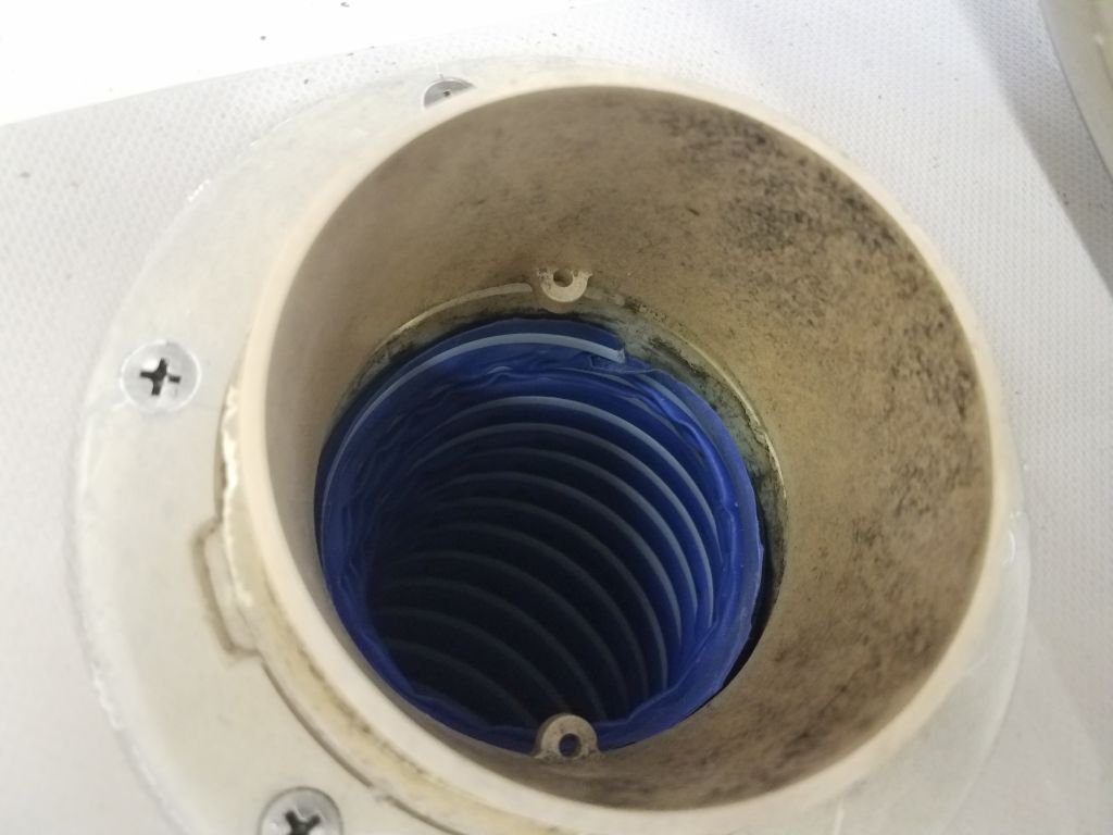
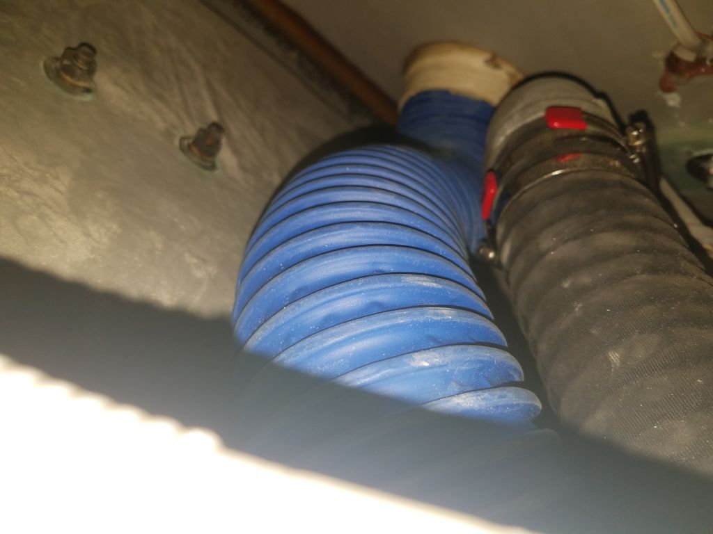
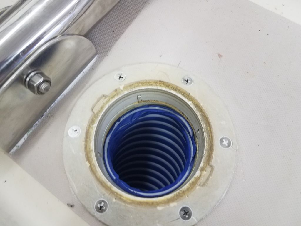
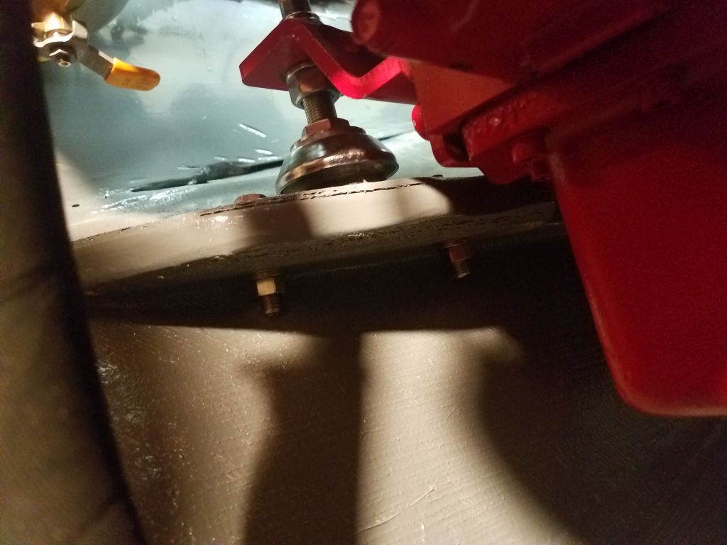
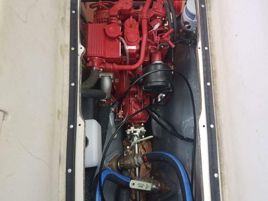
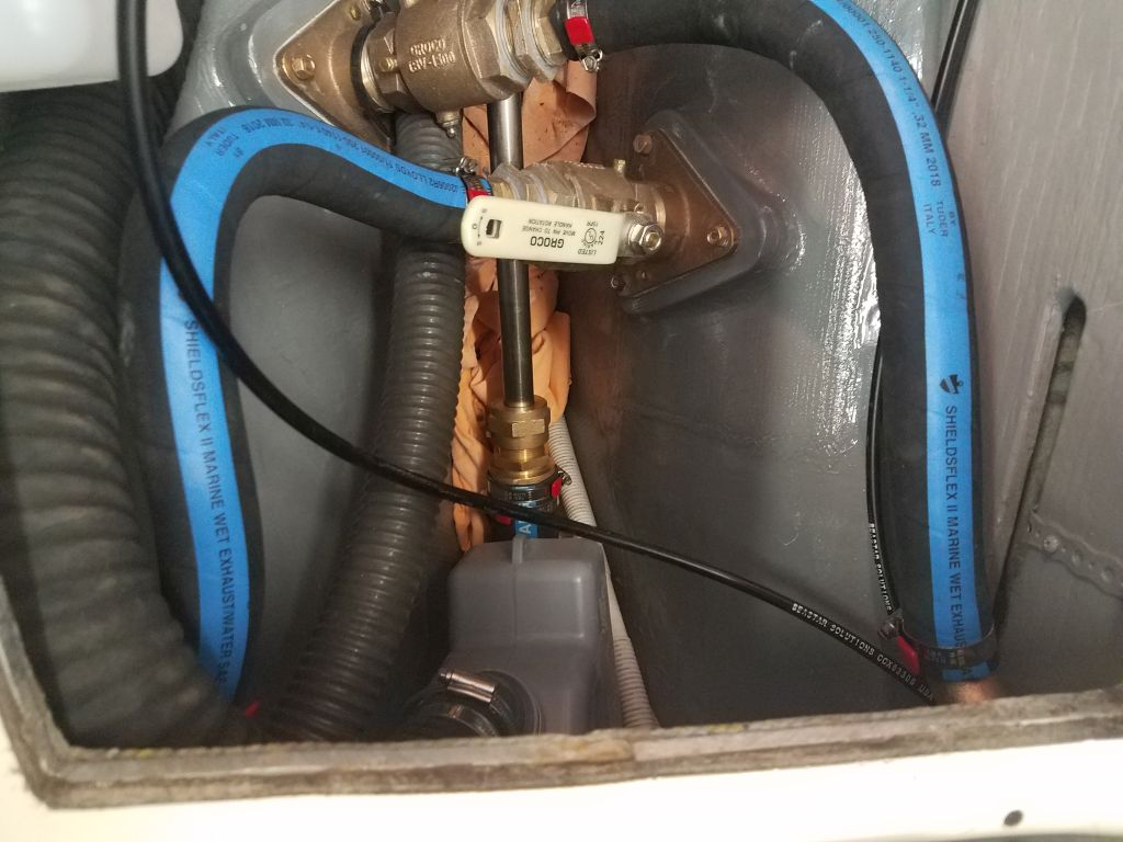
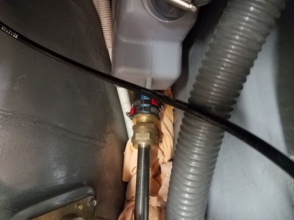
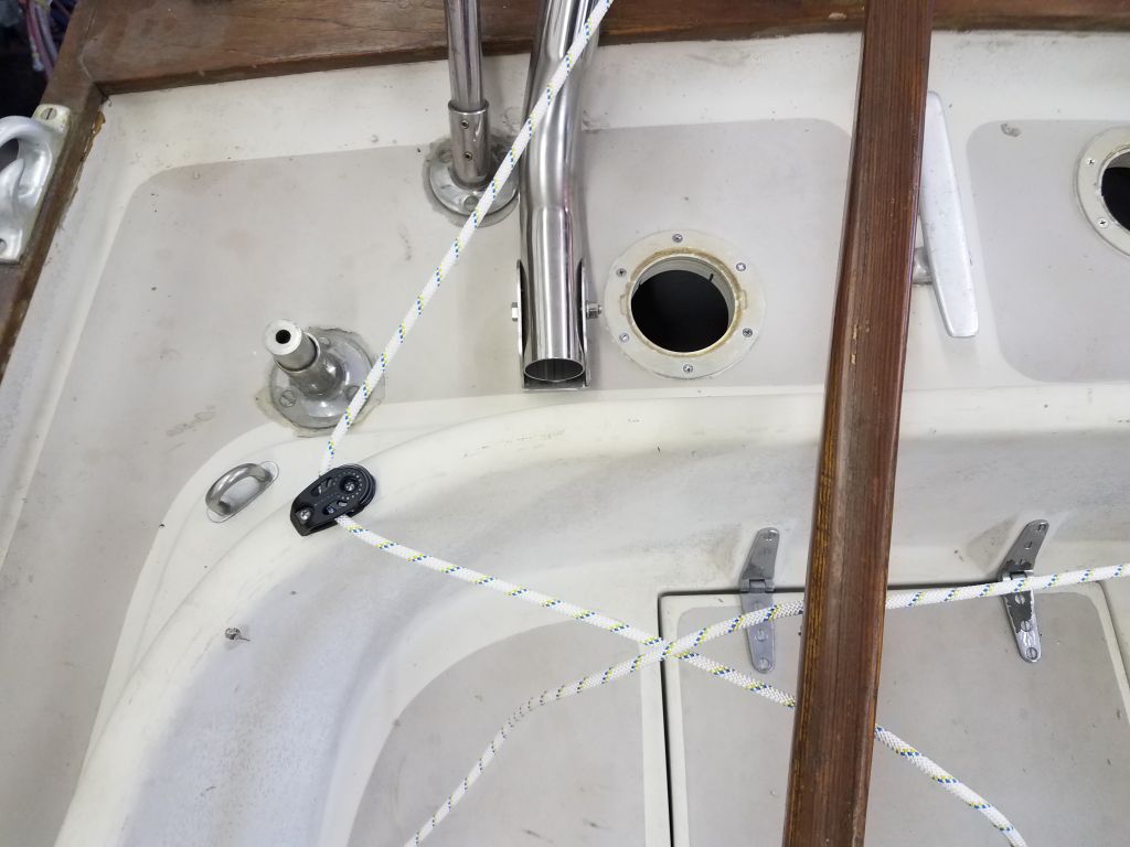
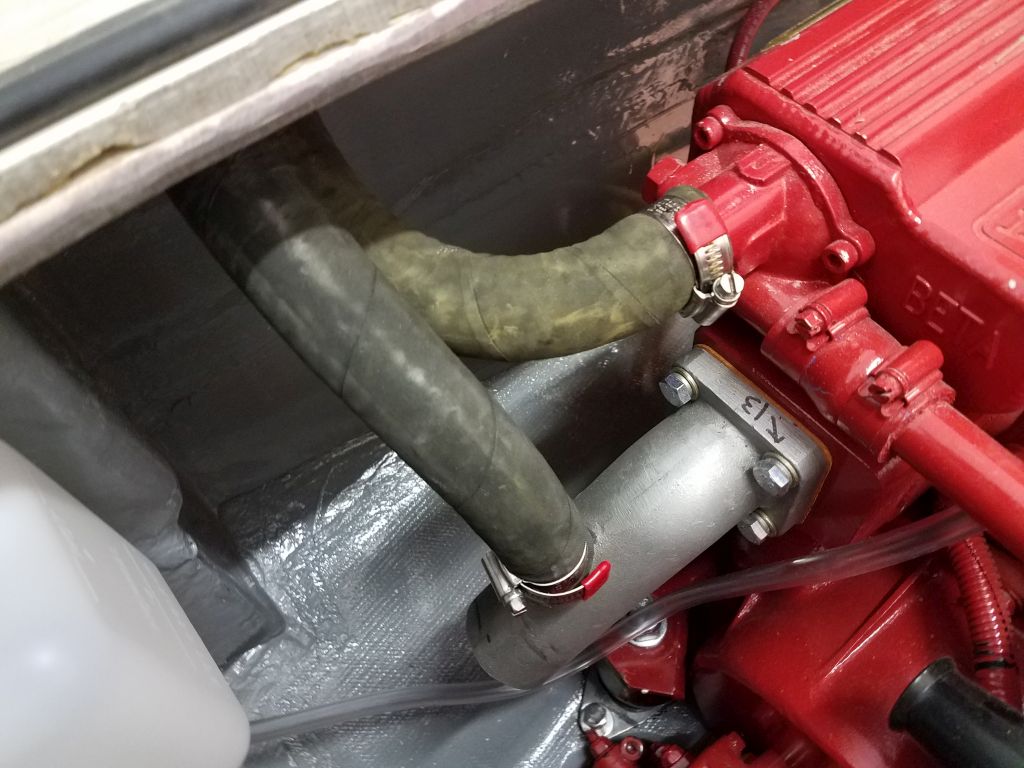
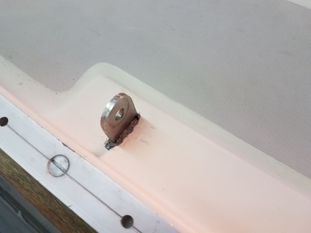
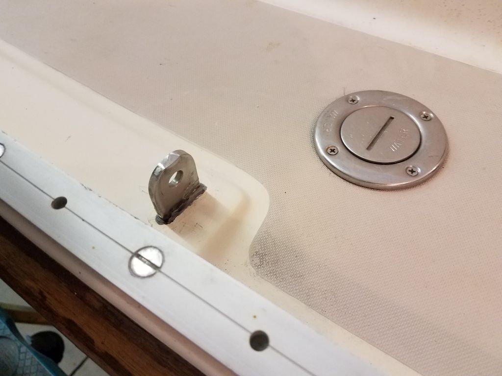
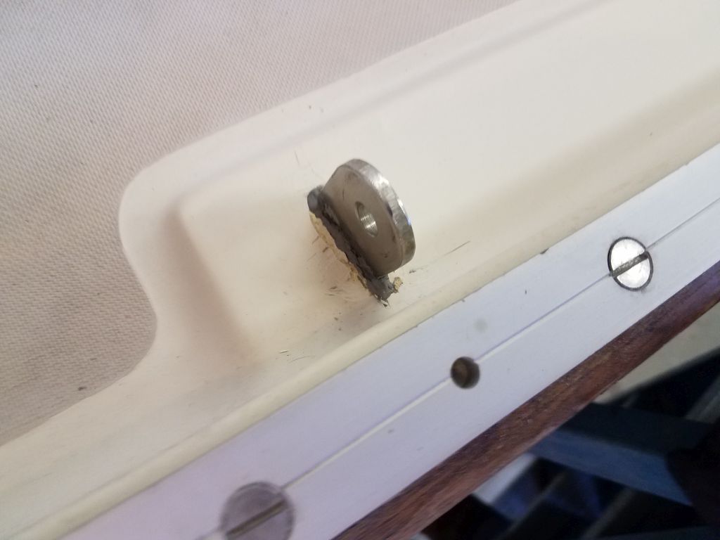
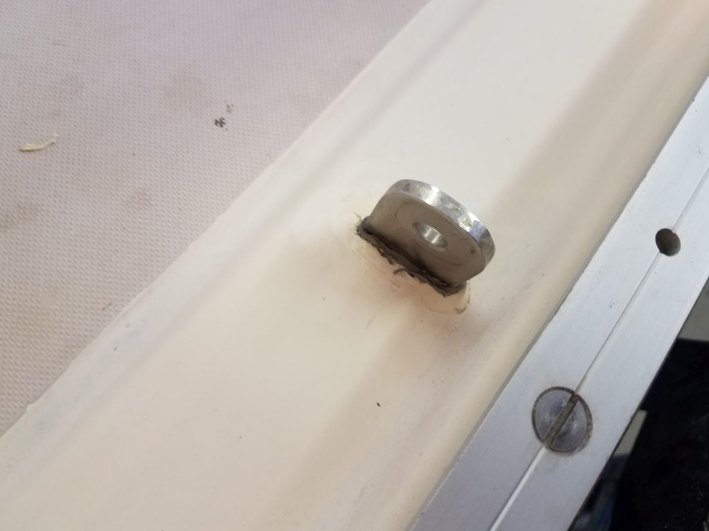
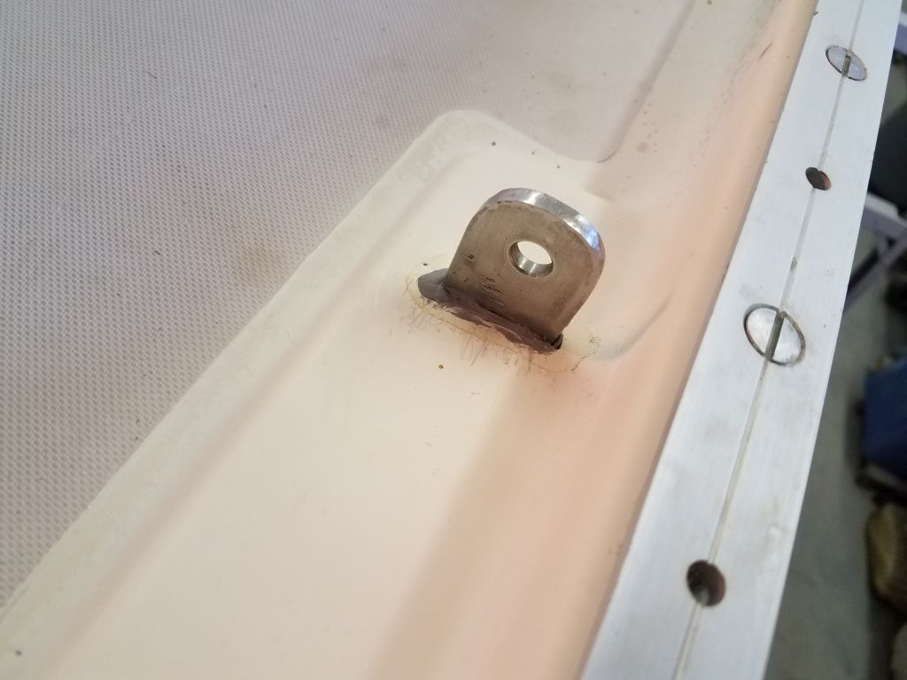
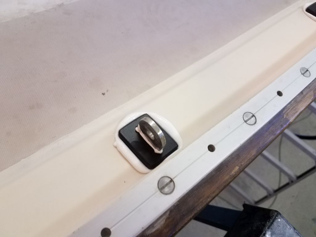
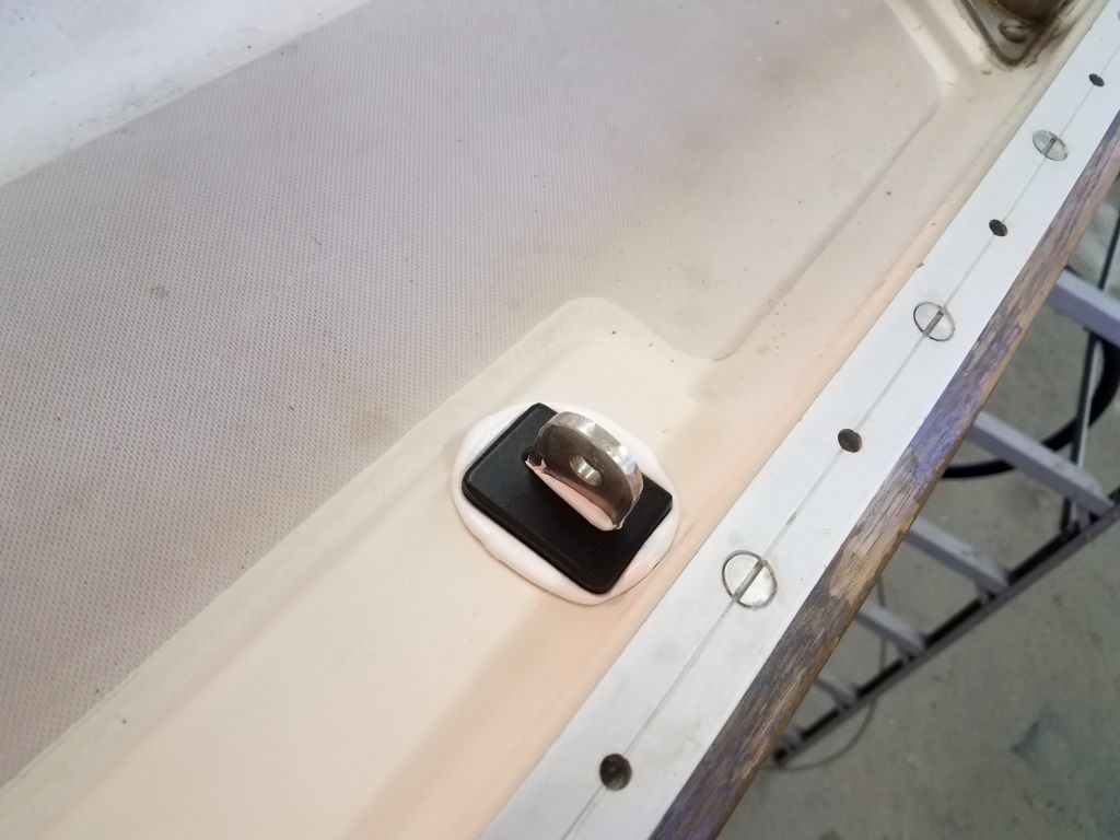
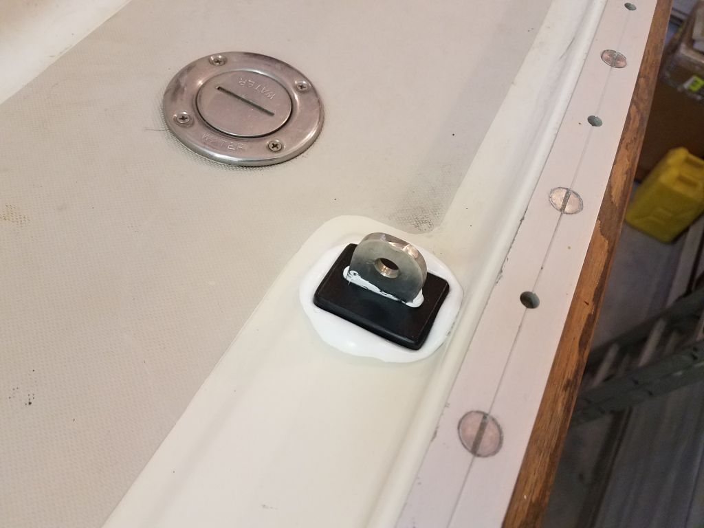
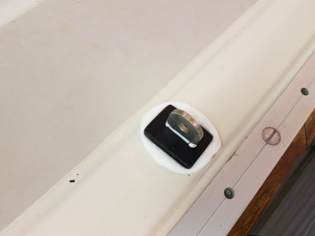
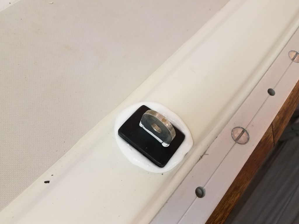
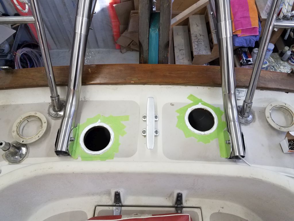
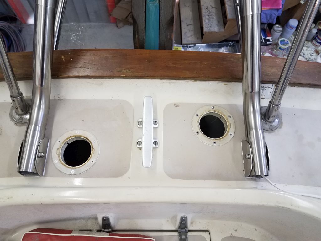
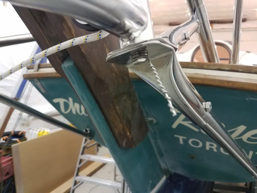
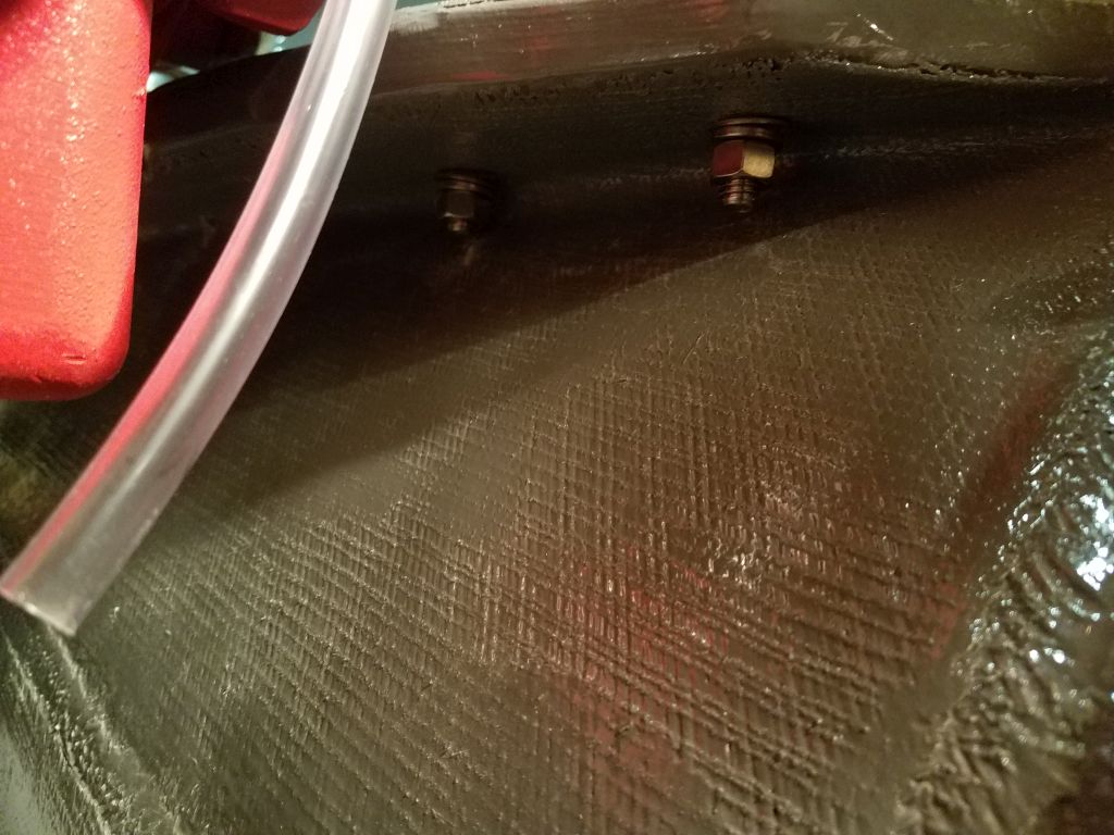
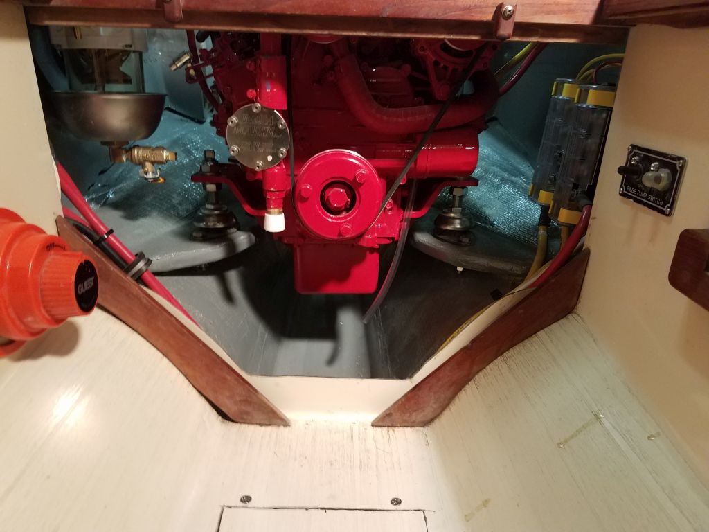
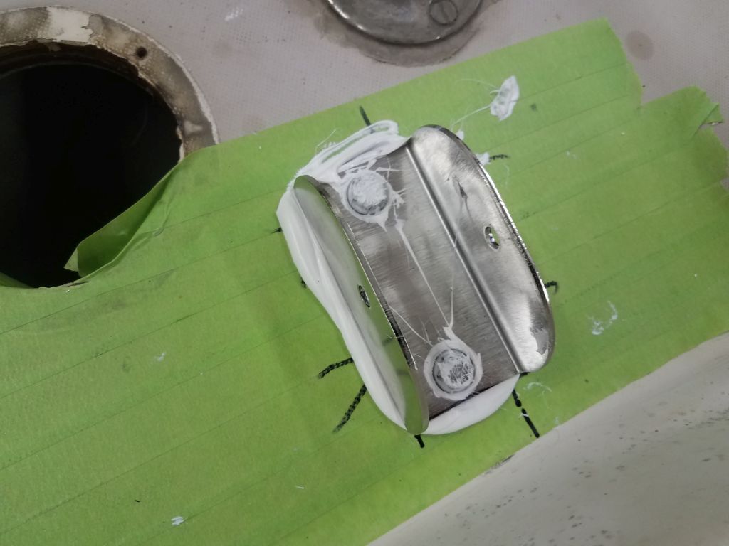
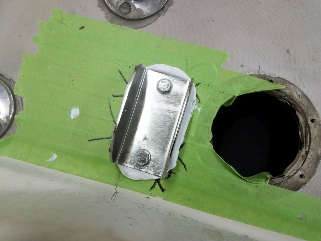
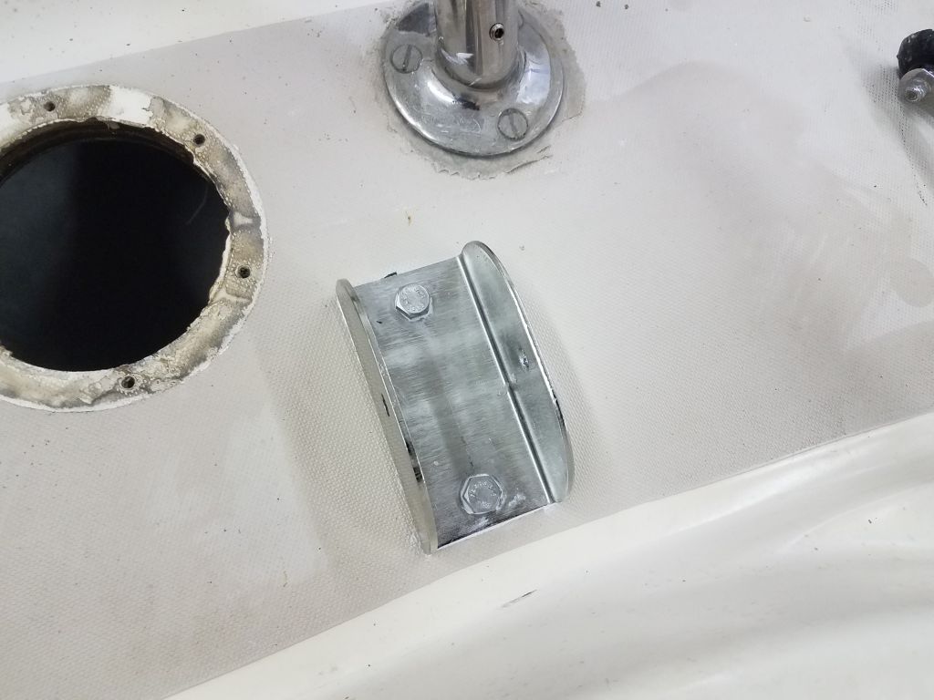
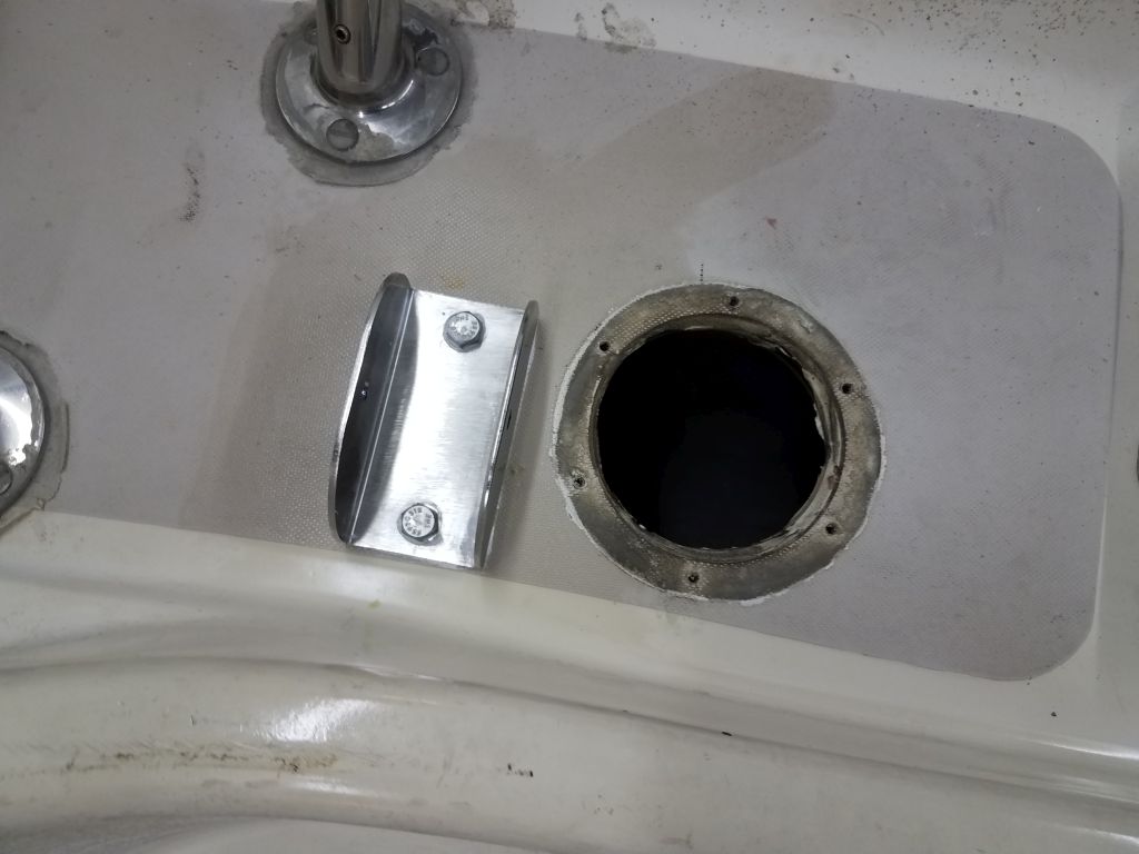
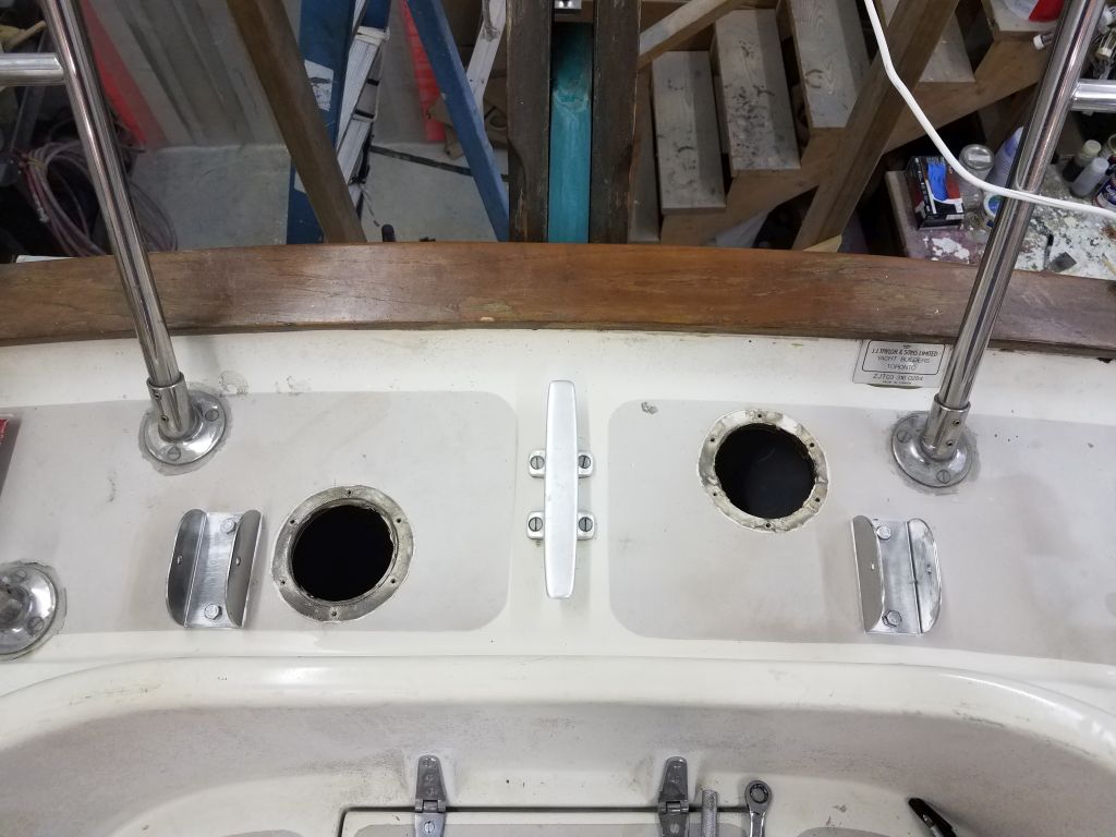
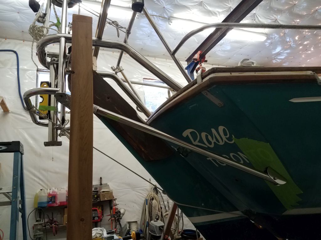
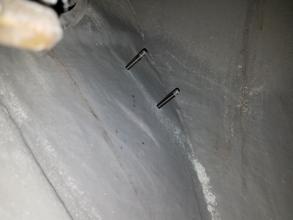
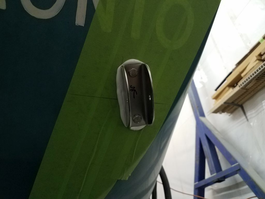
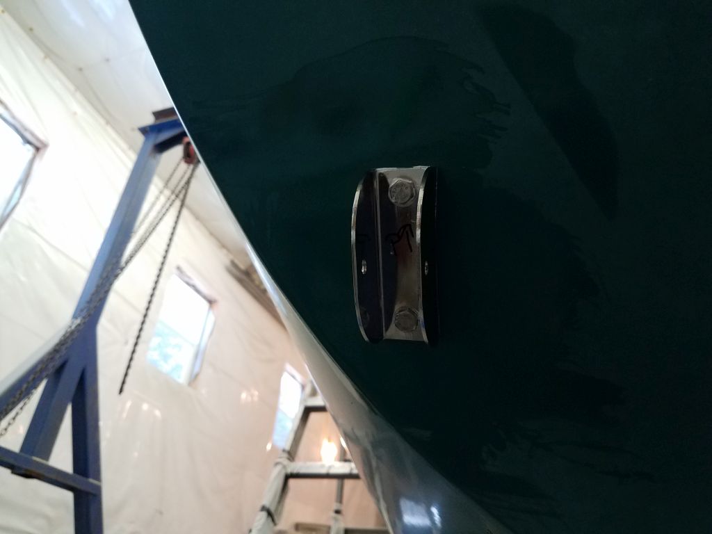
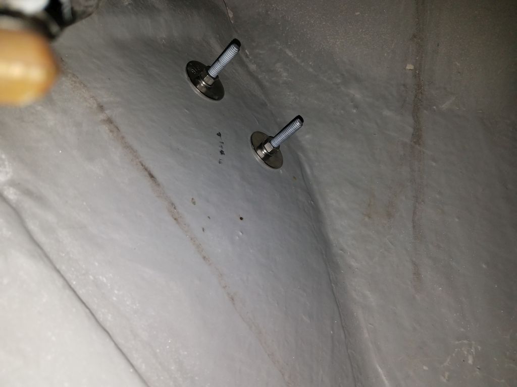
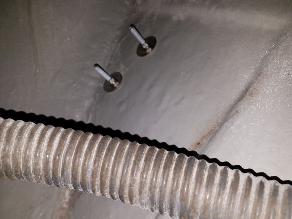
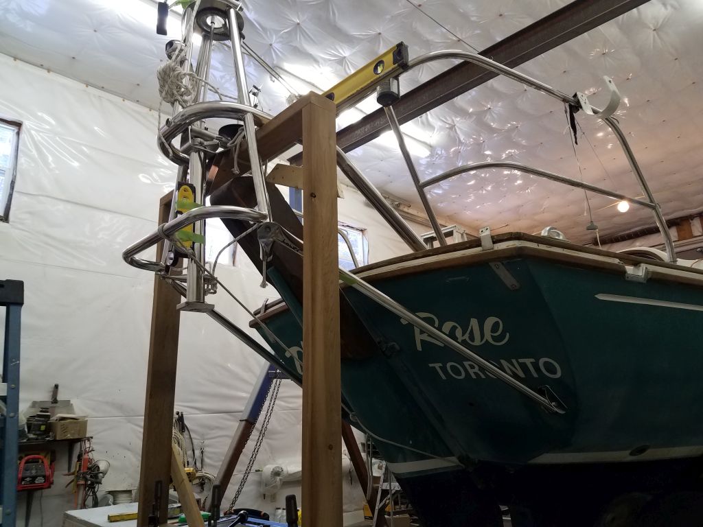
Now that the deck was ready after the epoxy cured overnight, I could move forward with the final installation of the two deck brackets for the main upper support tubes.  I followed all my habitual installation steps, including drilling and tapping the holes for the 5/16-18 hex bolts, countersinking the tops of the holes, removing the masking tape in the bonding area, and finally installing each fitting in a bed of sealant, using the 1/2″ backing plates below with large washers and nuts.  Access to the undersides of these fittings was possible through the nearby holes from the temporarily-removed cowl vent fittings.  On the port side, the rigid exhaust gooseneck against the transom made this access extremely tight.

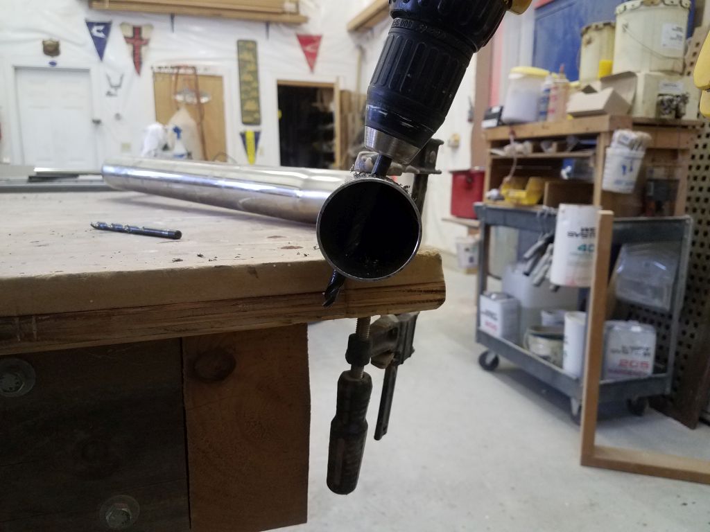
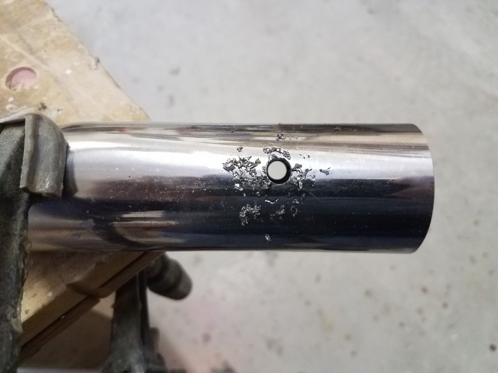
Before installing the support tubes for the final time and using marks I had made earlier before removing the tubes, I center-punched and drilled the through holes at the inboard (deck) ends for the bolt that would secure them to the deck brackets.

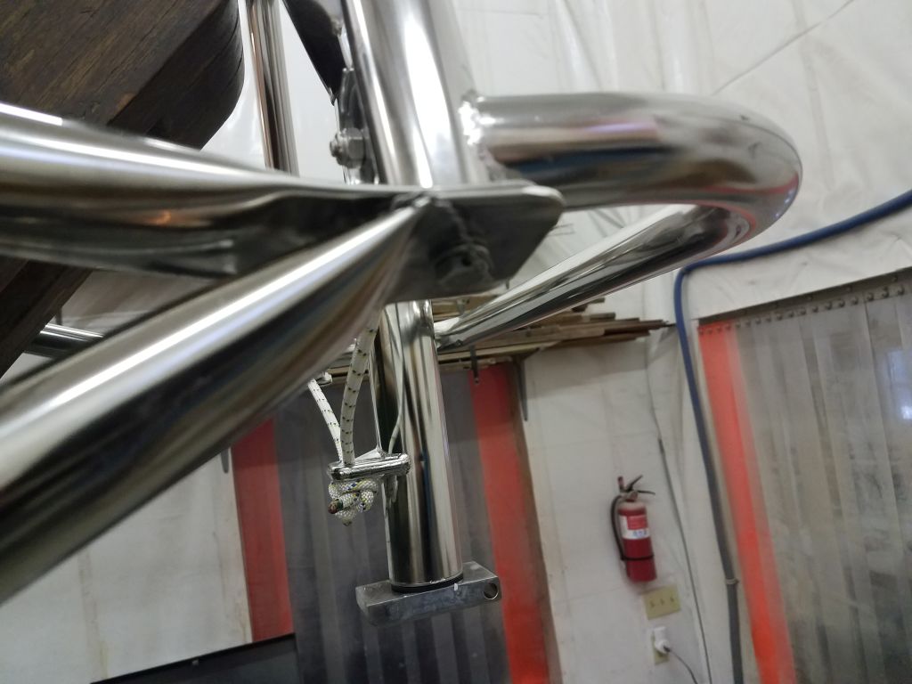
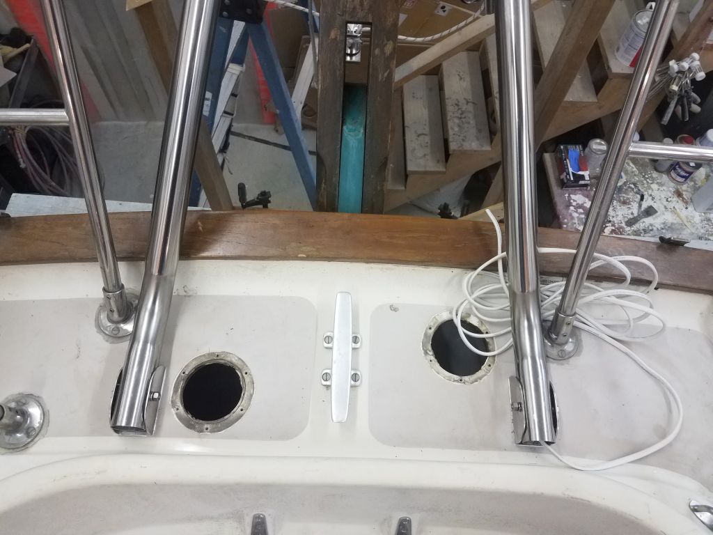
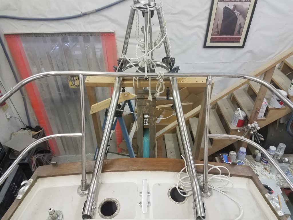
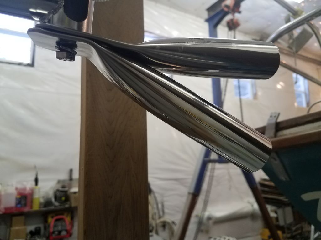
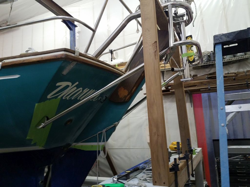
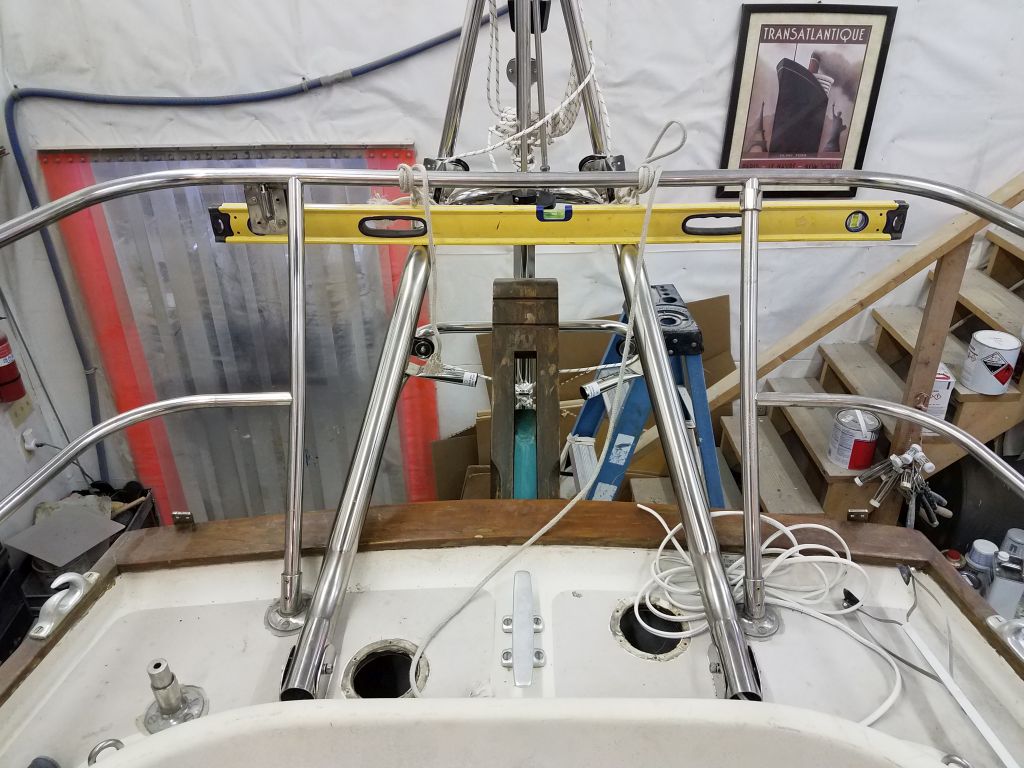
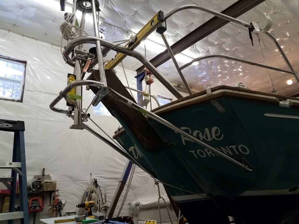
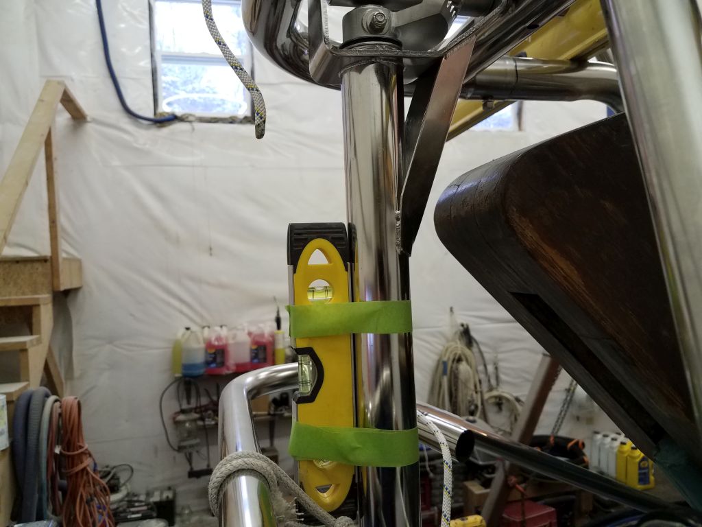
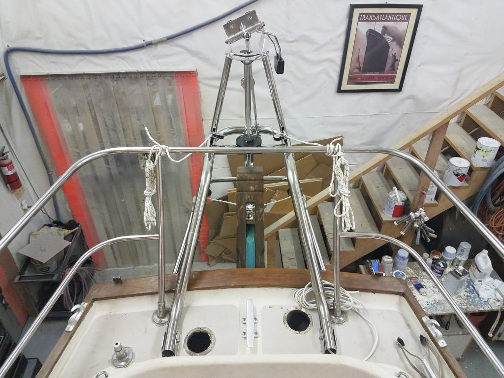
Now I could install the tubes for the last time, and once they were positioned correctly I installed the bolts through both ends, though for now I only hand-tightened the nuts.  I checked level in both directions throughout the process.

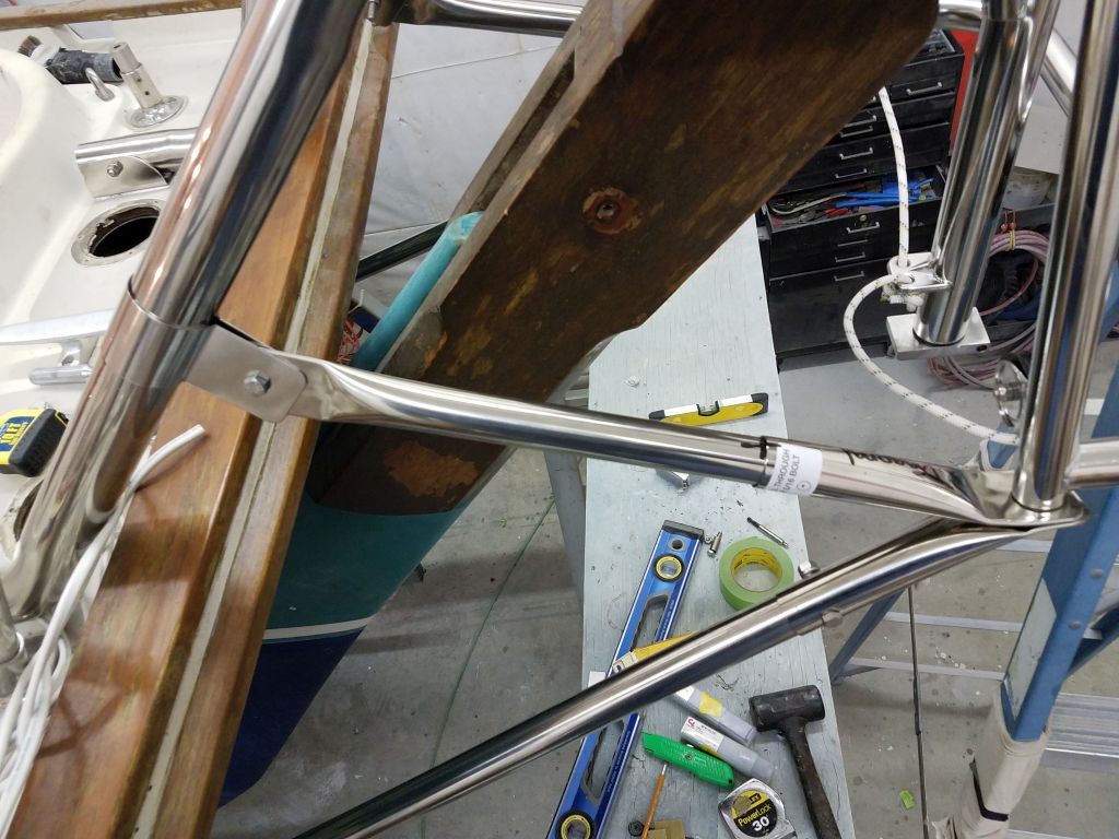
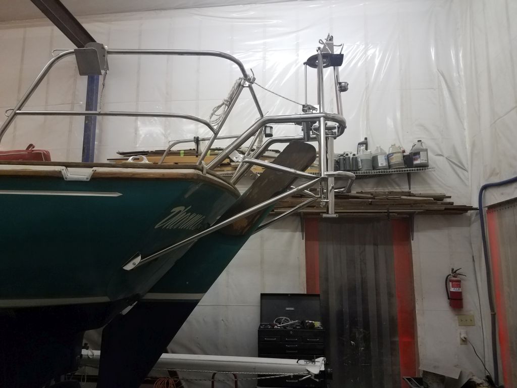
Now I turned to the two lower support tubes, which would run between the base of the Monitor frame and the transom on each side.  To begin, I loosely installed a pair of end fittings–one for the eventual diagonal braces on top, and another for the lower brace on the bottom–on each lower corner of the frame, using the threaded holes provided.  I made sure to face the pilot hole locations outward, which would make drilling the bolt holes later much easier.  (During my first installation on a sistership, I’d given no thought to this and the pilot holes ended up on the inside, making access for drilling much more difficult.)

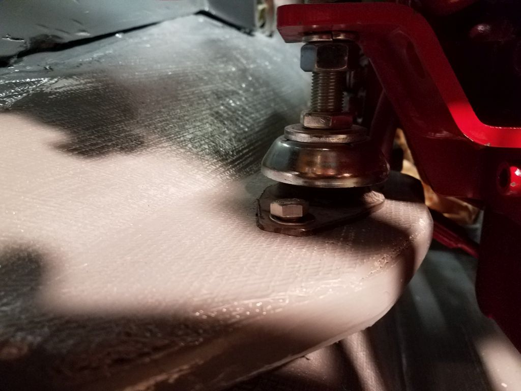
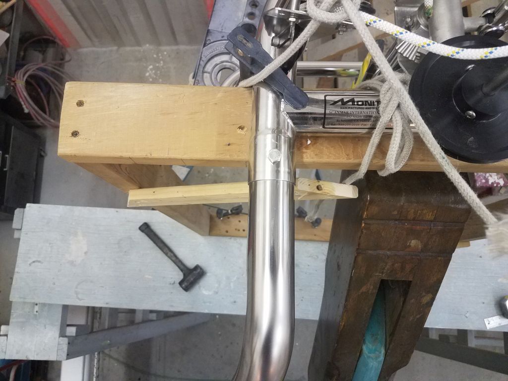
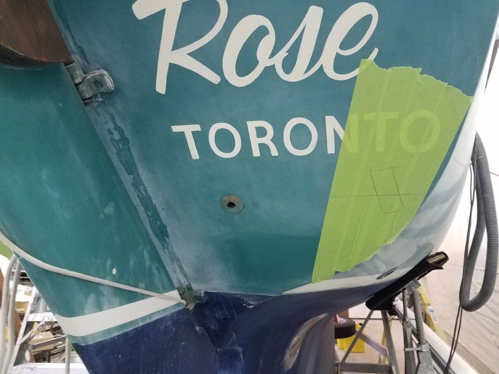
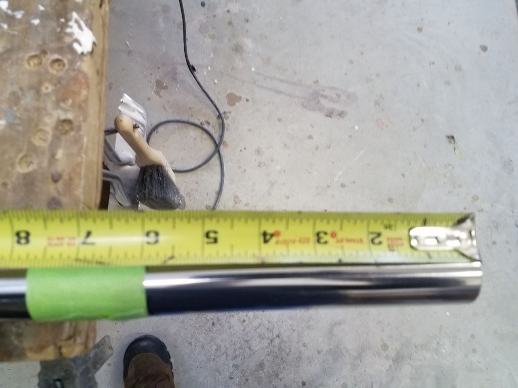
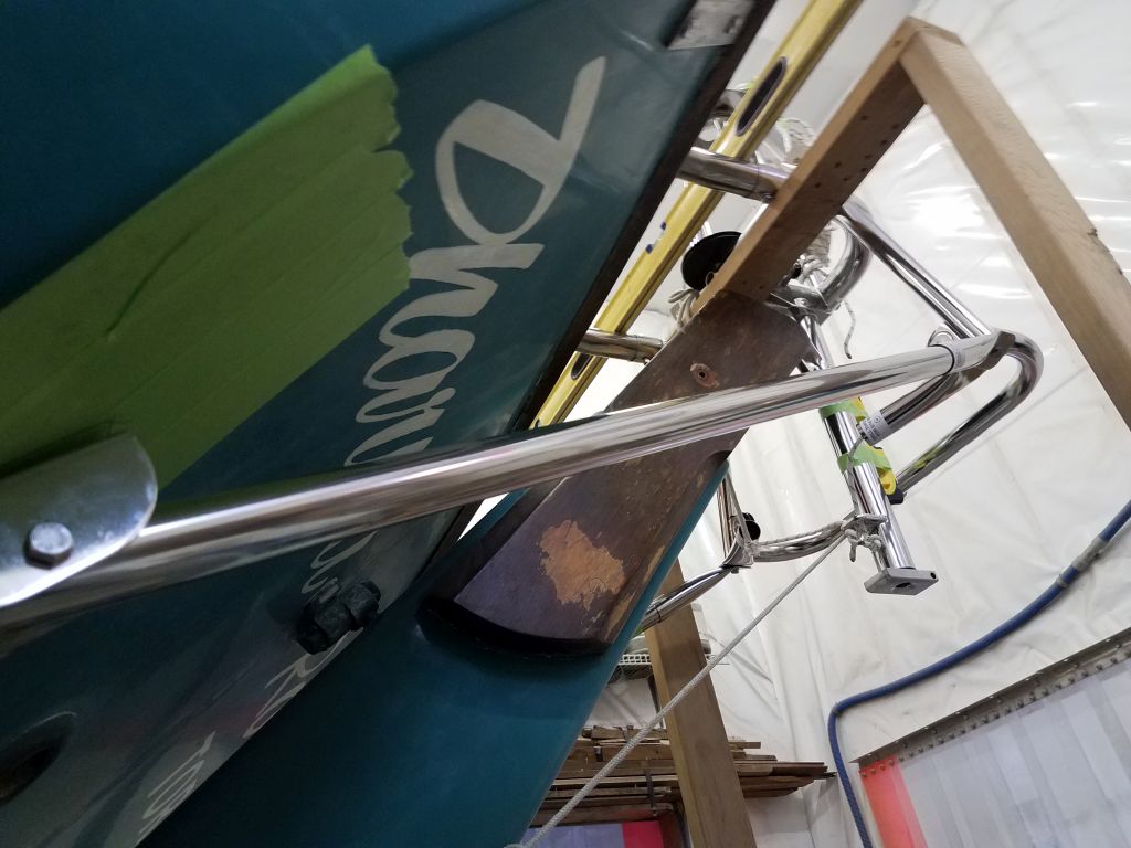
The lower tubes came from the factory with excess length, so starting with general guidance from the instructions and boat-specific data sheet, I laid out the general locations for the transom brackets on the hull, checking inside the boat to ensure the way was clear there.  I chose a height and lateral position that would keep the mounts close to the transom edge and triangulate as well as possible with the frame above for strength and rigidity.  Holding the bracket, with the tube pre-mounted within, against the hull in my chosen position (starting with the starboard side), and the other end of the tube against the socket at the frame, I could estimate how much length I needed to remove in order to fit the tube.  In this case, it was about 6″.  I couldn’t really get a picture of the mockup process.  Down on the bench, I cut off the excess length.

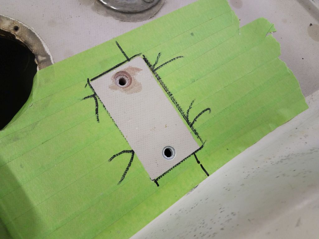
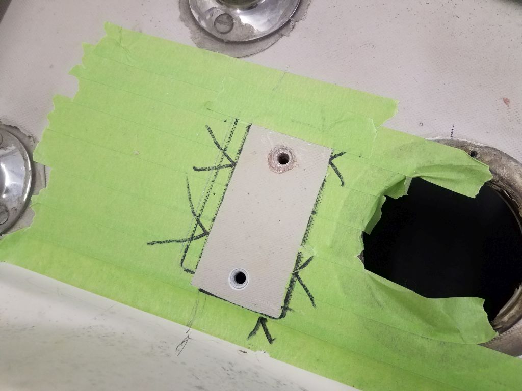
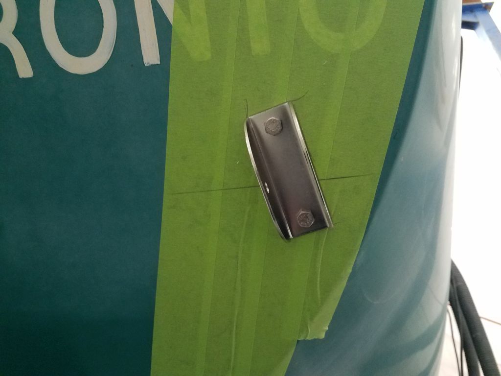
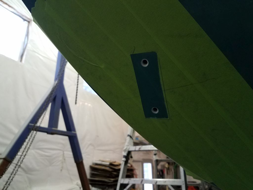
Now I could insert the tube properly in the socket at the Monitor frame, and then position the hull bracket appropriately on the transom.  The length worked as I’d anticipated, so I marked the lower bracket mounting hole (which was exposed) and traced around the bracket so I could re-align it and mark the upper hole once I removed the tube for installation.  With the tube unfastened from the bracket, I drilled and tapped the hull for the mounting bolts and temporarily installed the fitting in place, along with the tube.

Next, I repeated this process on the port side.  I’d already determined that the same tube length would work here (one never knows given the not-infrequent asymmetry of boats), so I cut off the 6″ and, after marking the bracket location on the hull as before, dry-mounted the port side as well.

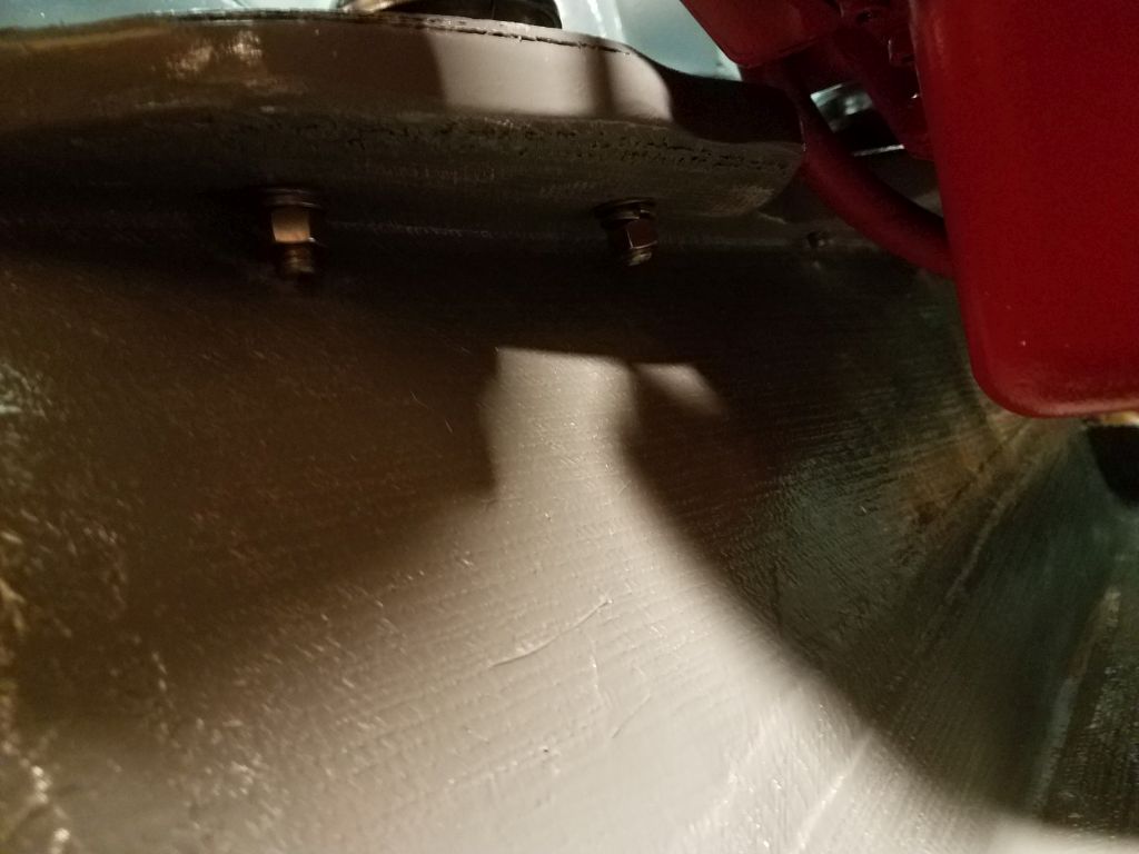
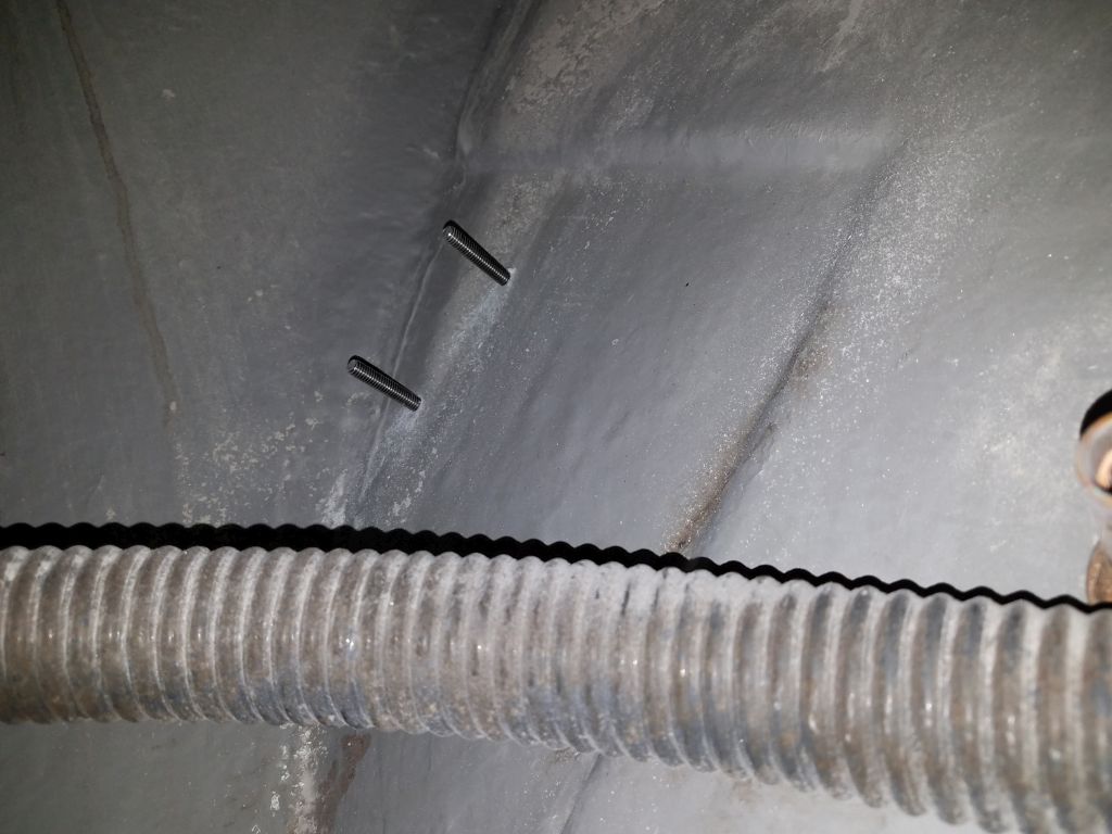
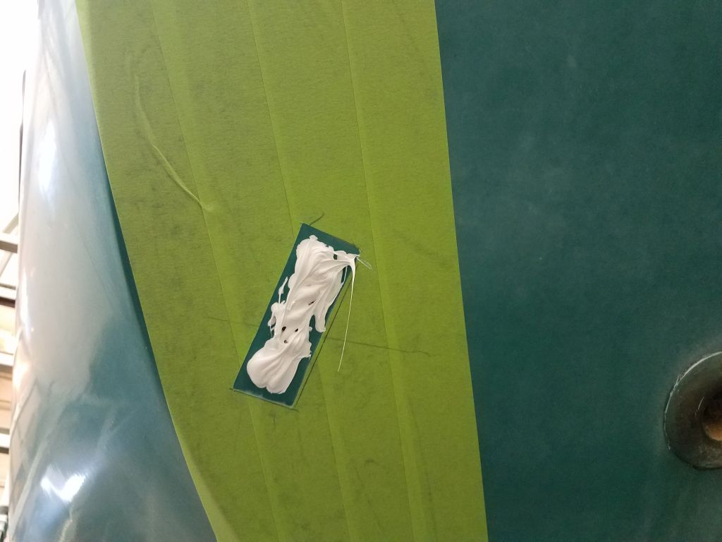
Removing the bolts from the bracket ends of the tubes, I scored the masking tape around the brackets, then removed the brackets so I could prepare for final installation, which I did next, after countersinking the hole tops and applying sealant.  I drove in the 5/16″ bolts tightly from outside, and from within installed large washers and nuts to complete the installation, after which I reinstalled the support tubes.

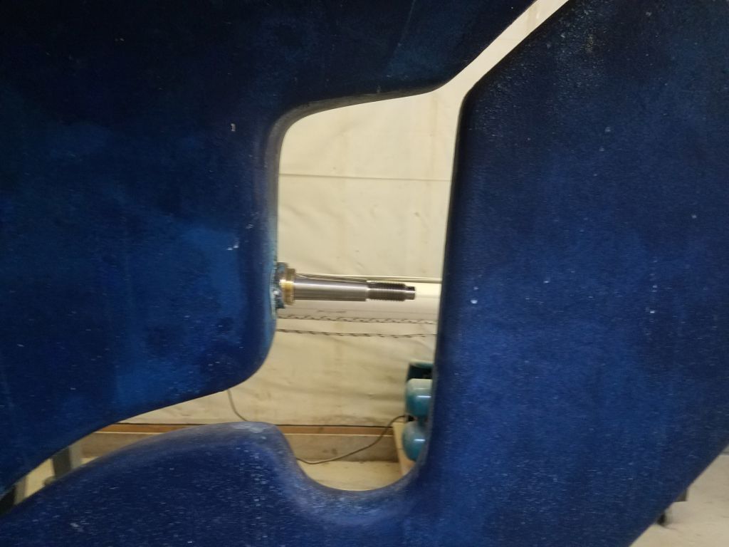
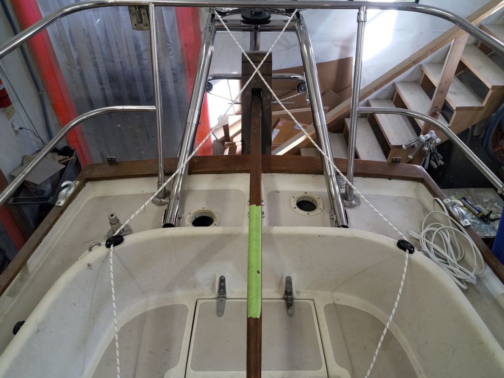
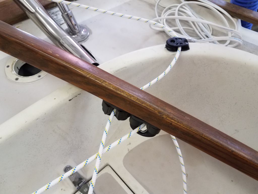
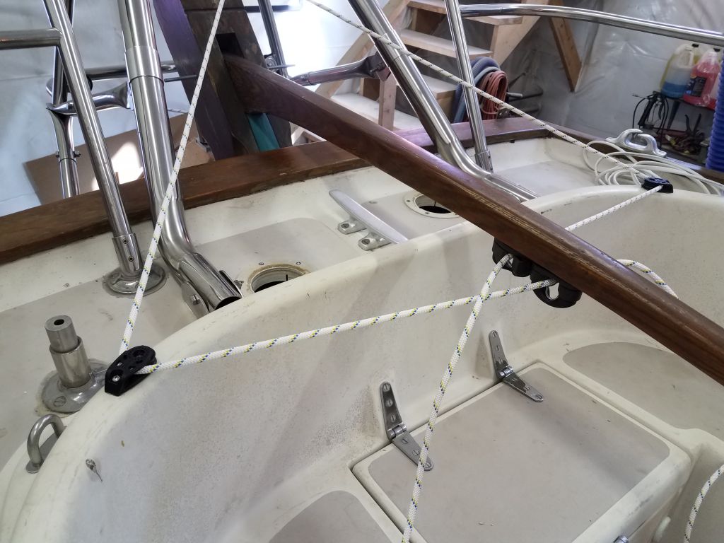
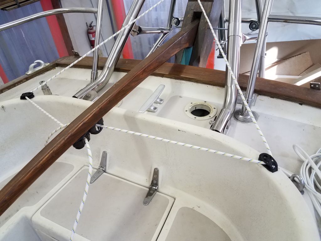
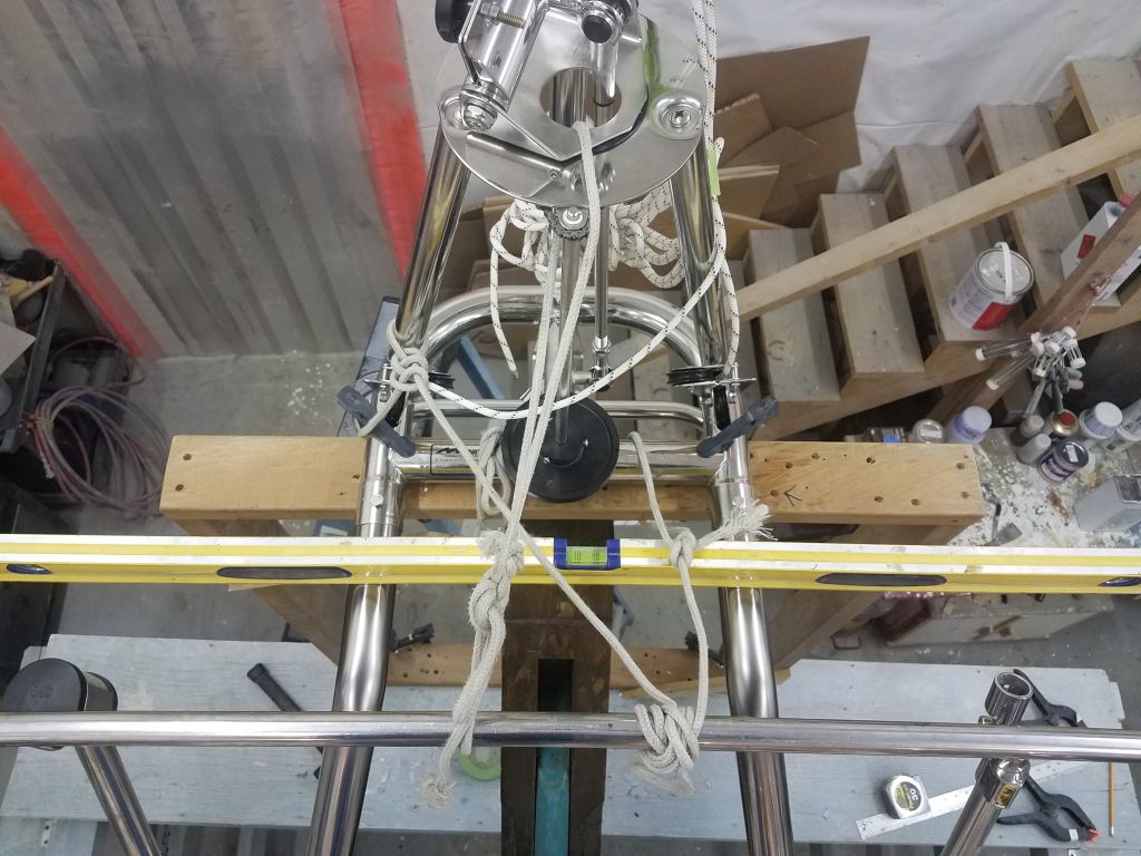
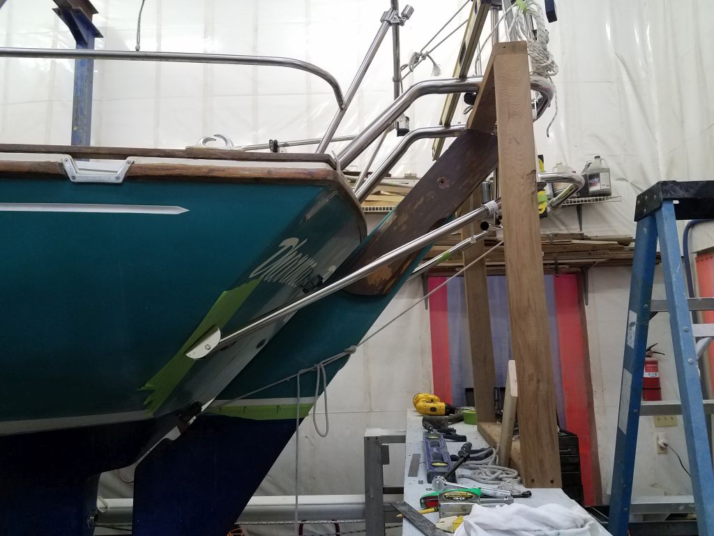
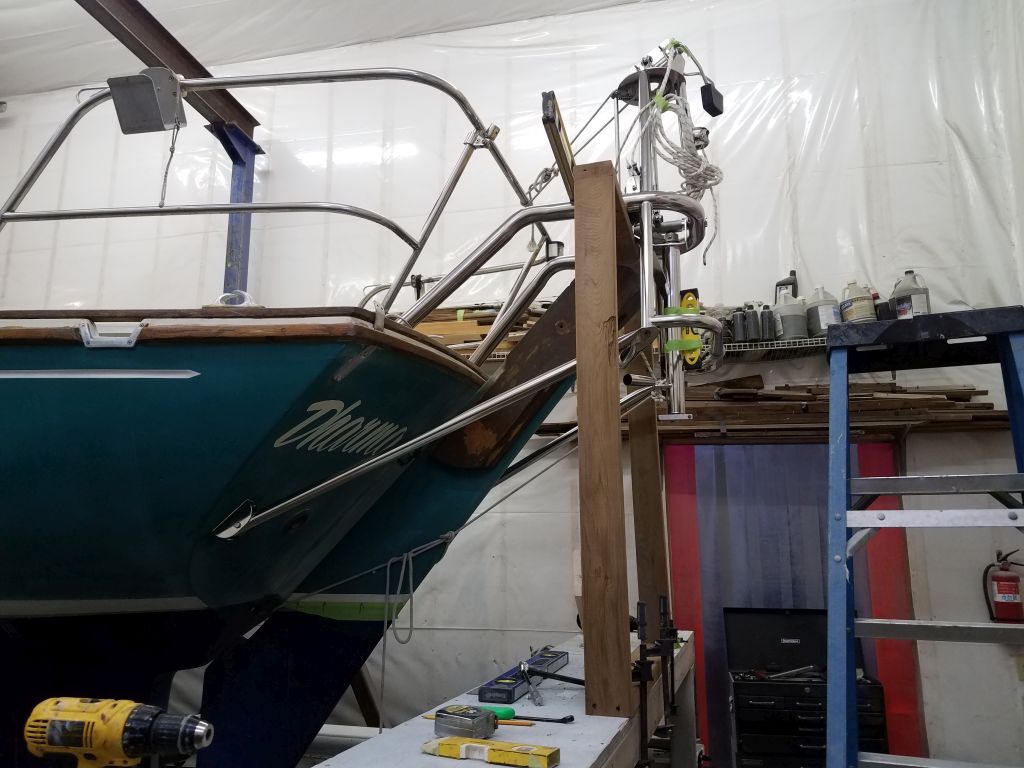
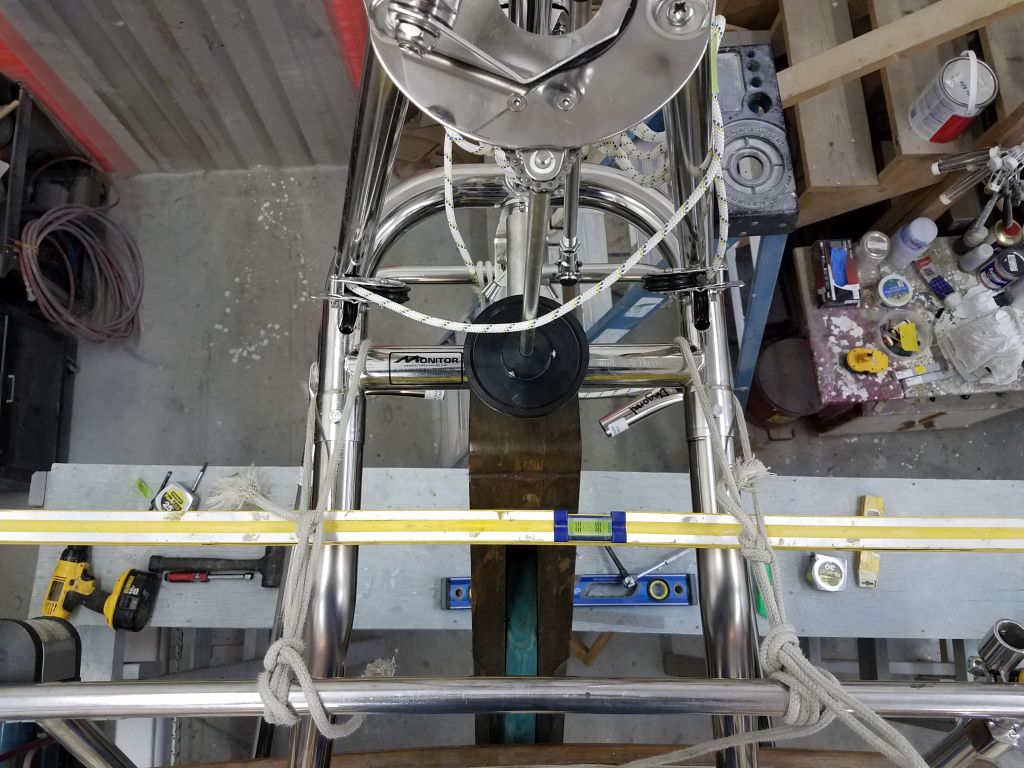
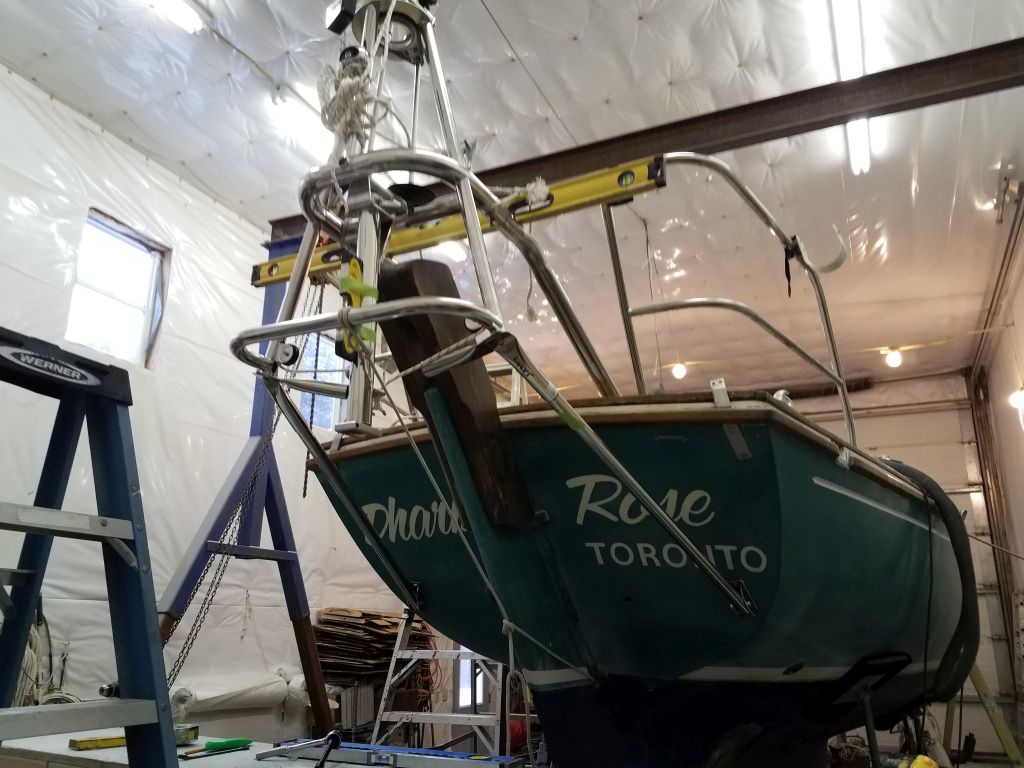
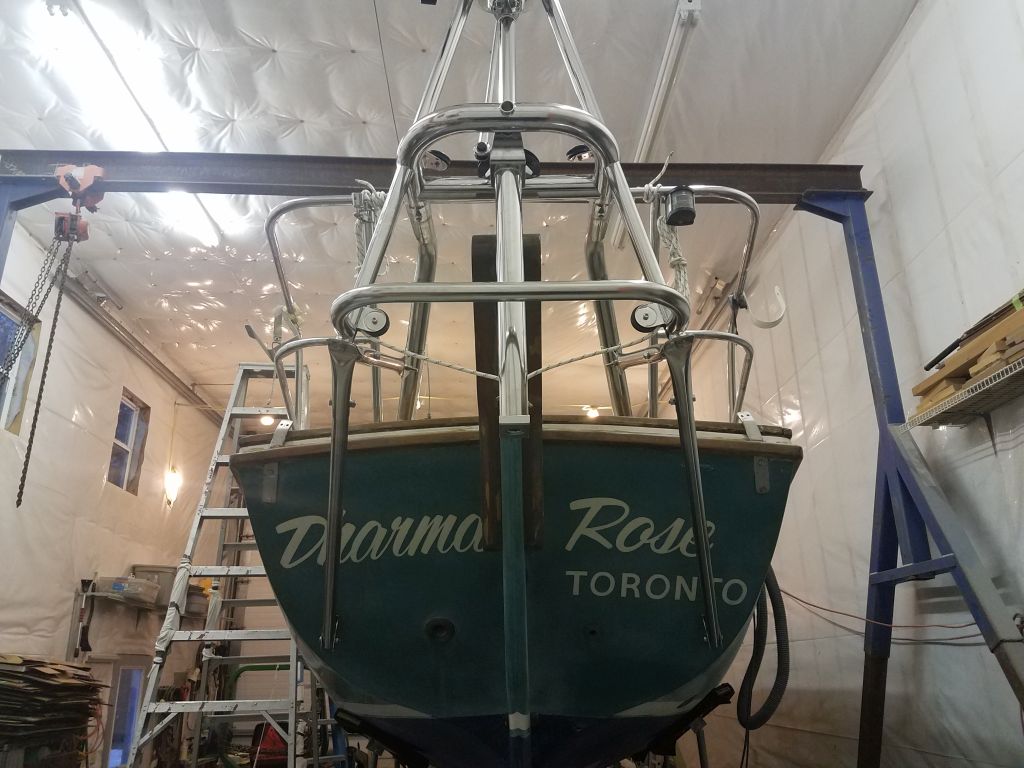
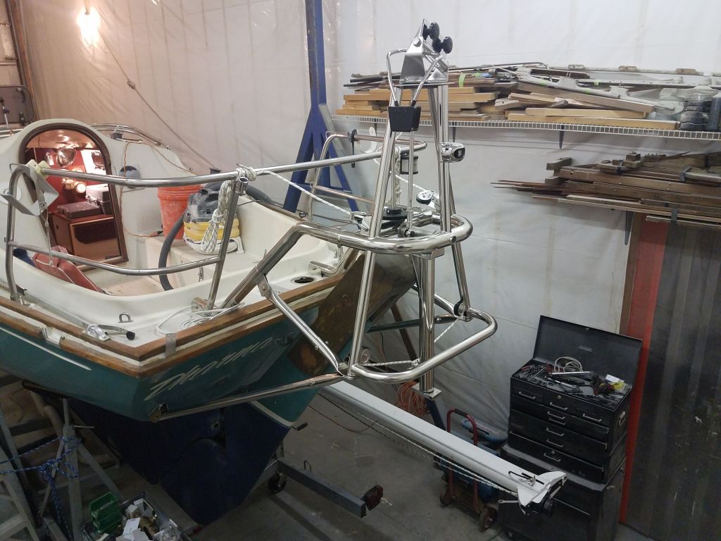
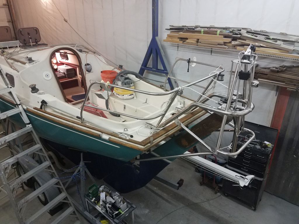
Now I could get rid of the wooden support frame, and make any final adjustments to the framework and installation to fine-tune the level in either direction.  I tied a pair of lines between the Monitor frame and stern pulpit, pulling the whole arrangement up just slightly and maintaining level from side to side.  Then, I removed the frame and, from the shop floor, I adjusted the vertical positioning as needed with a third line that I led forward to the rudder.

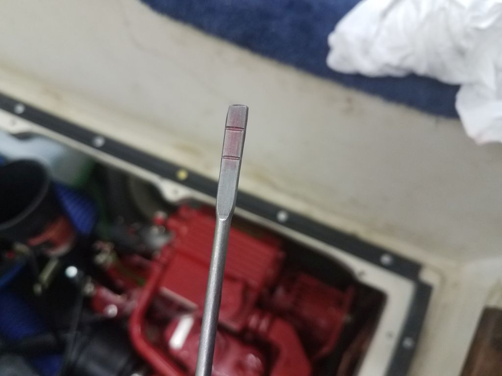
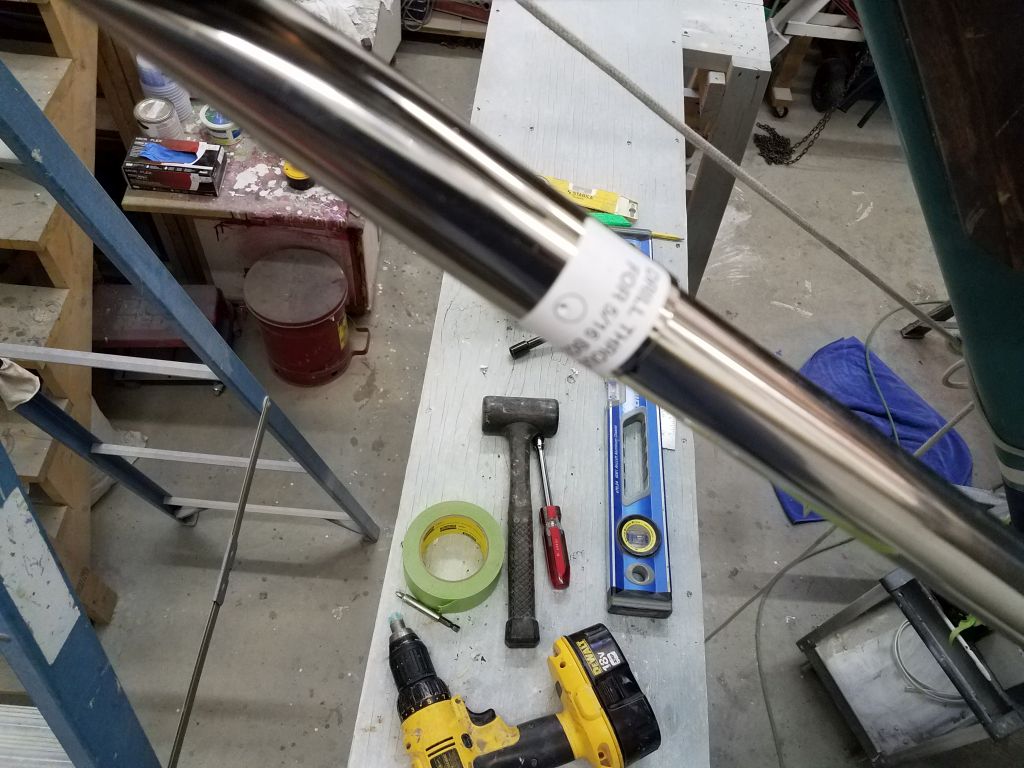
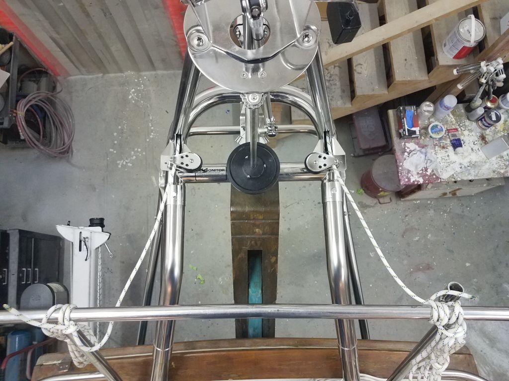
Satisfied with this final-final position of the frame, I could drill through the lower support tubes and their sockets for the bolts that would secure them.  This was much easier working from outside the frame and from the staging plank that I left in place for this purpose.  For these and all the other 5/16″ through-holes in this installation, I found it easier to start the hole with a 1/4″ bit, and then enlarge it with the proper bit afterwards.

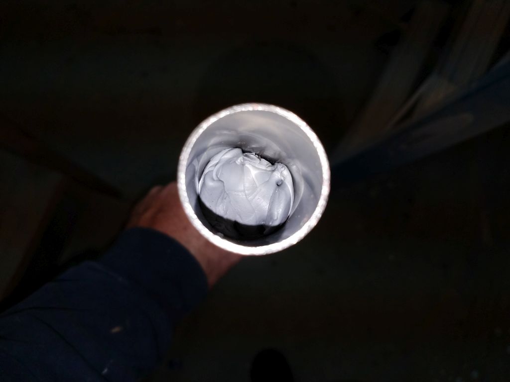
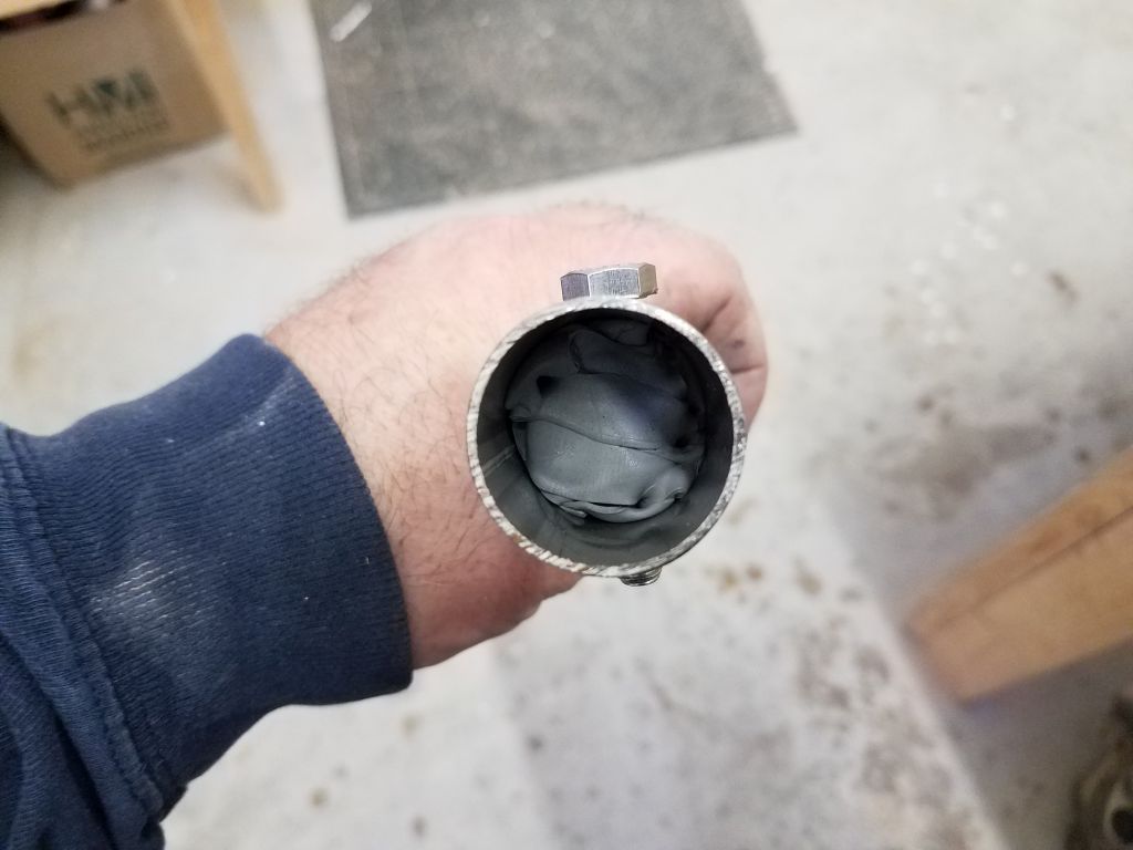
With the holes drilled, I removed the tubes and installed the compression sleeves inside, using butyl tape to hold these in place (I don’t know why I didn’t think of using that before).  Then, I could immediately reinstall the tubes and secure the bolts just hand tight.

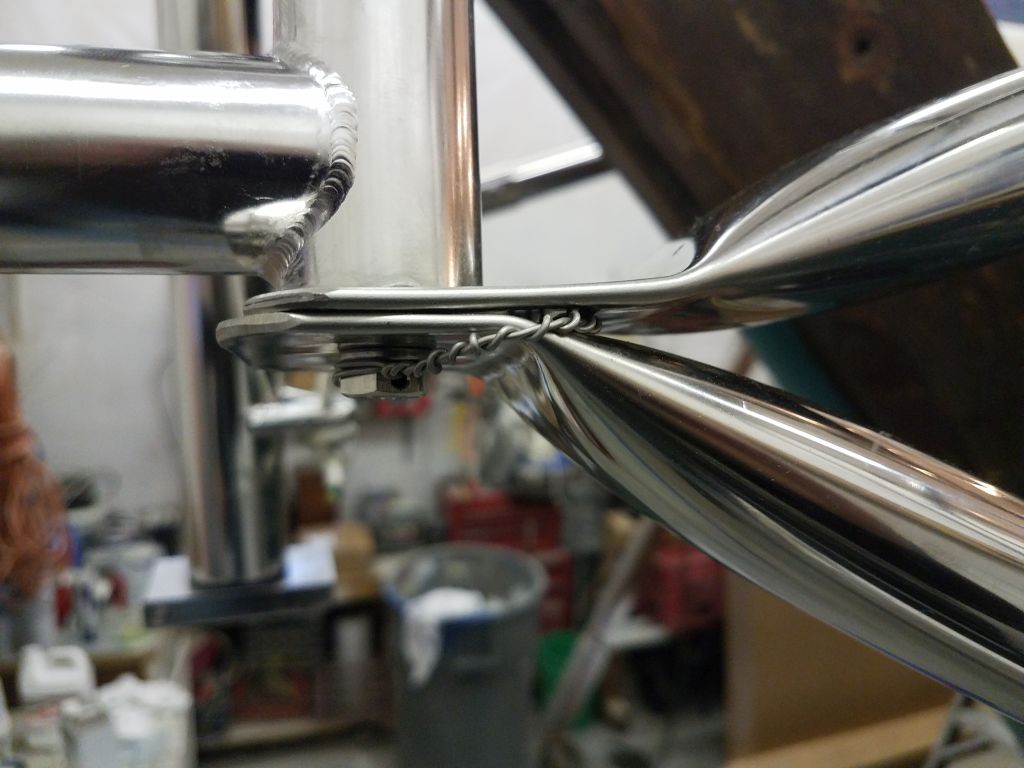
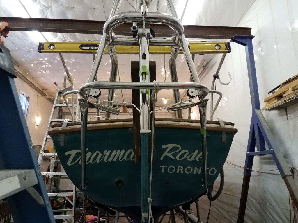
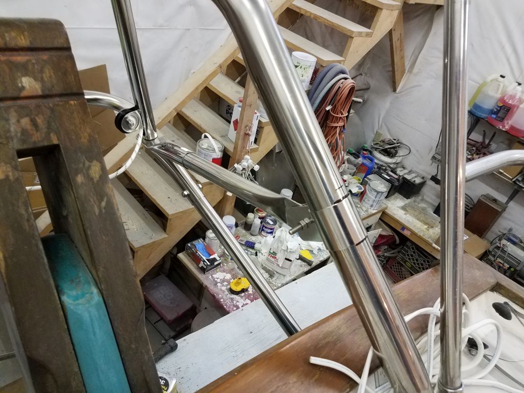
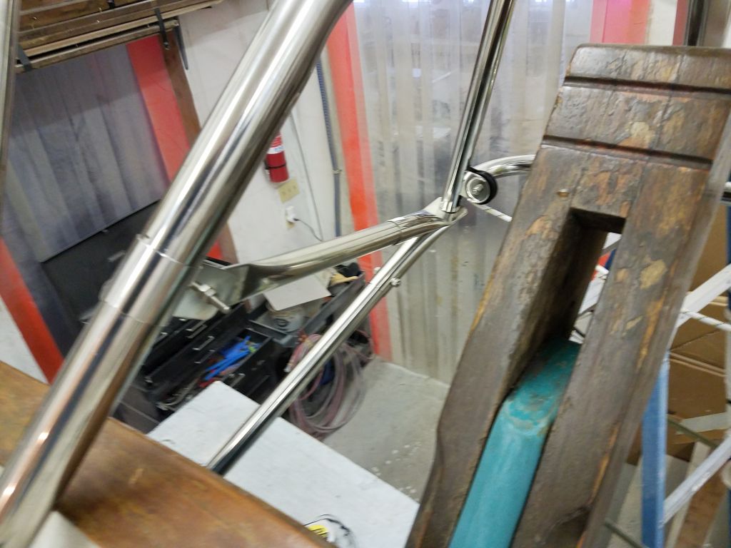
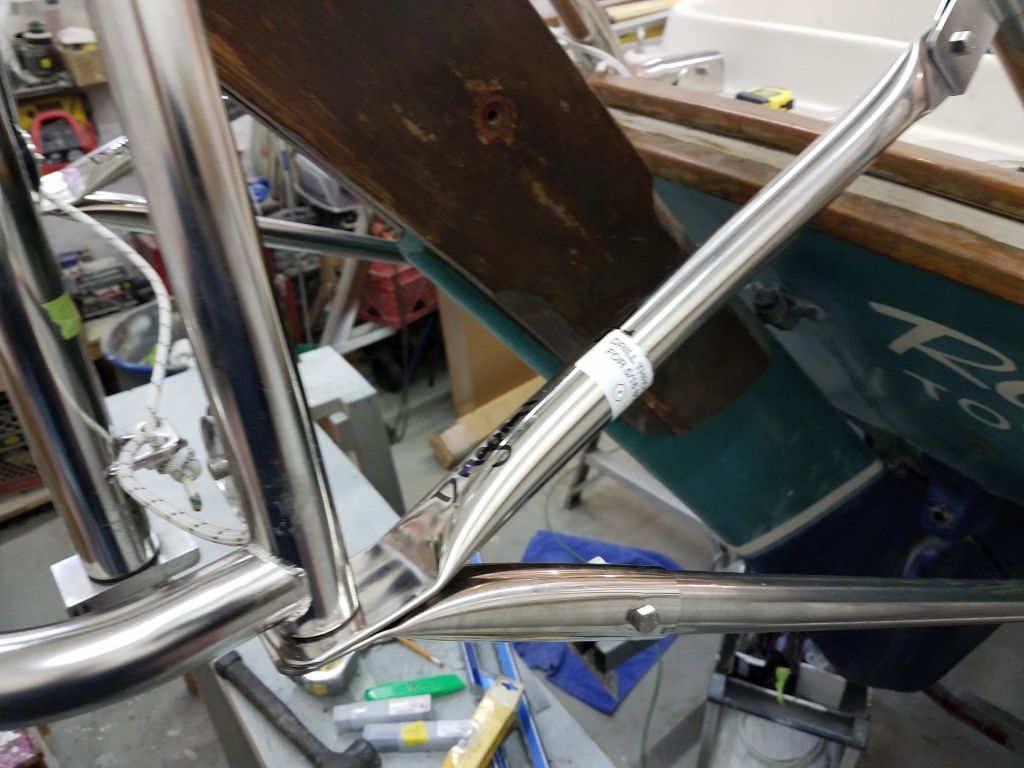
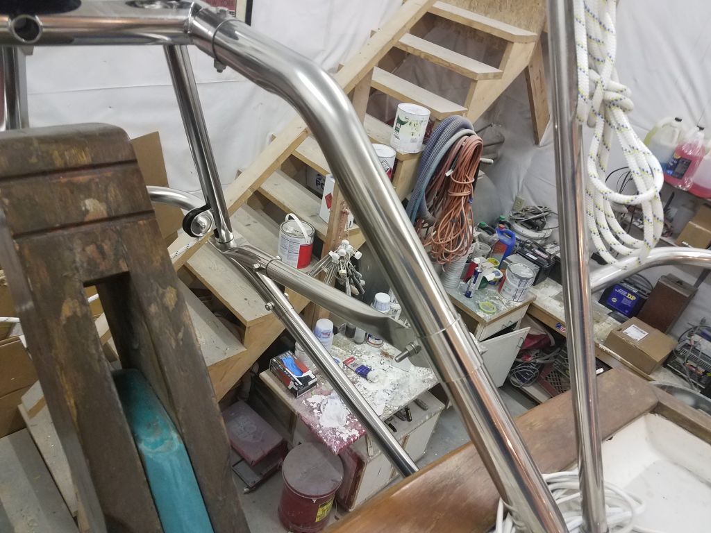
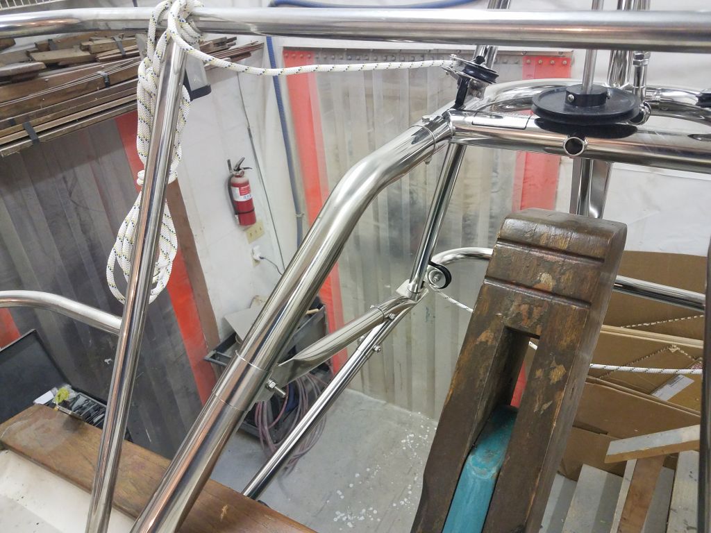
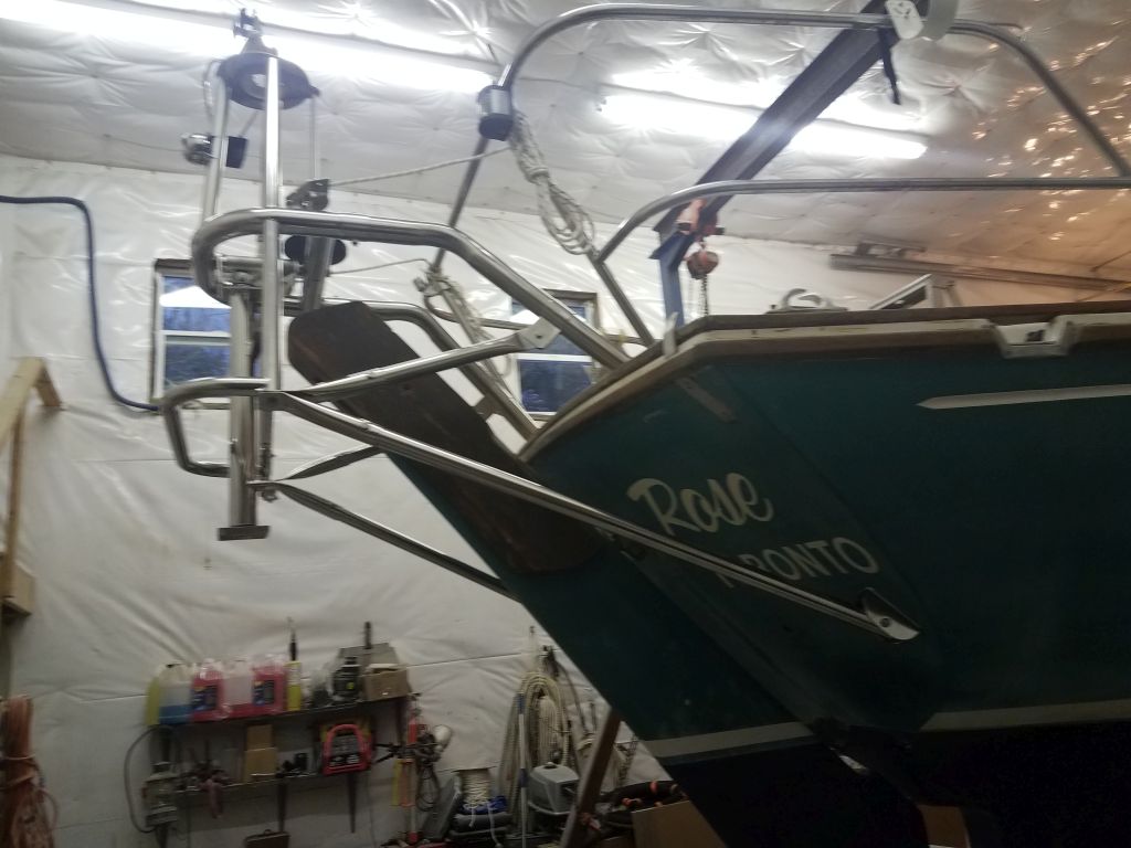
This installation, with its unique mounting and long support tubes, required a final set of tubes called diagonals, which ran between the bottom of the Monitor frame and the upper support tubes themselves.  I’d already installed the socket ends at the frame, so now I installed the supplied brackets around the upper tubes and installed the flattened end of the diagonal tubes.  The inner position really could go just about anywhere, but logically fell about 9″ above the lower curve of the upper tubes, which nicely triangulated the other framing elements.

Then, holding the tube against the socket end, I determined how much to cut off (again, these tubes were supplied intentionally over-long).  Removing the tube, I marked both sides to remove the same length, and cut off the excess, then installed both sides in their sockets and with the upper tube brackets.

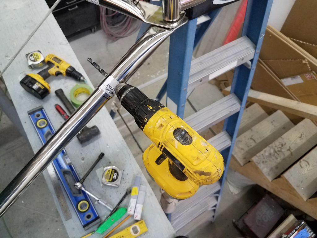
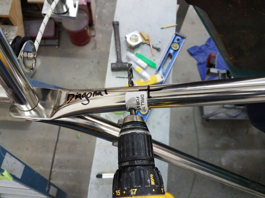
Now I drilled through the diagonal tubes at the socket ends for the final bolts.  On my previous installation, I’d struggled with the drilling, partly because of poor drill bits and partly because my drilling access then from the inside of the frame was so much more difficult.  For the current installation, I’d prepared ahead with six-each brand new 1/4″ and 5/16″ drill bits on hand, but completed all the holes through the stainless steel frame using only one of each with no trouble.

With the final holes drilled, I removed the diagonals once again and installed the compression tubes within, then installed them and secured the bolts.

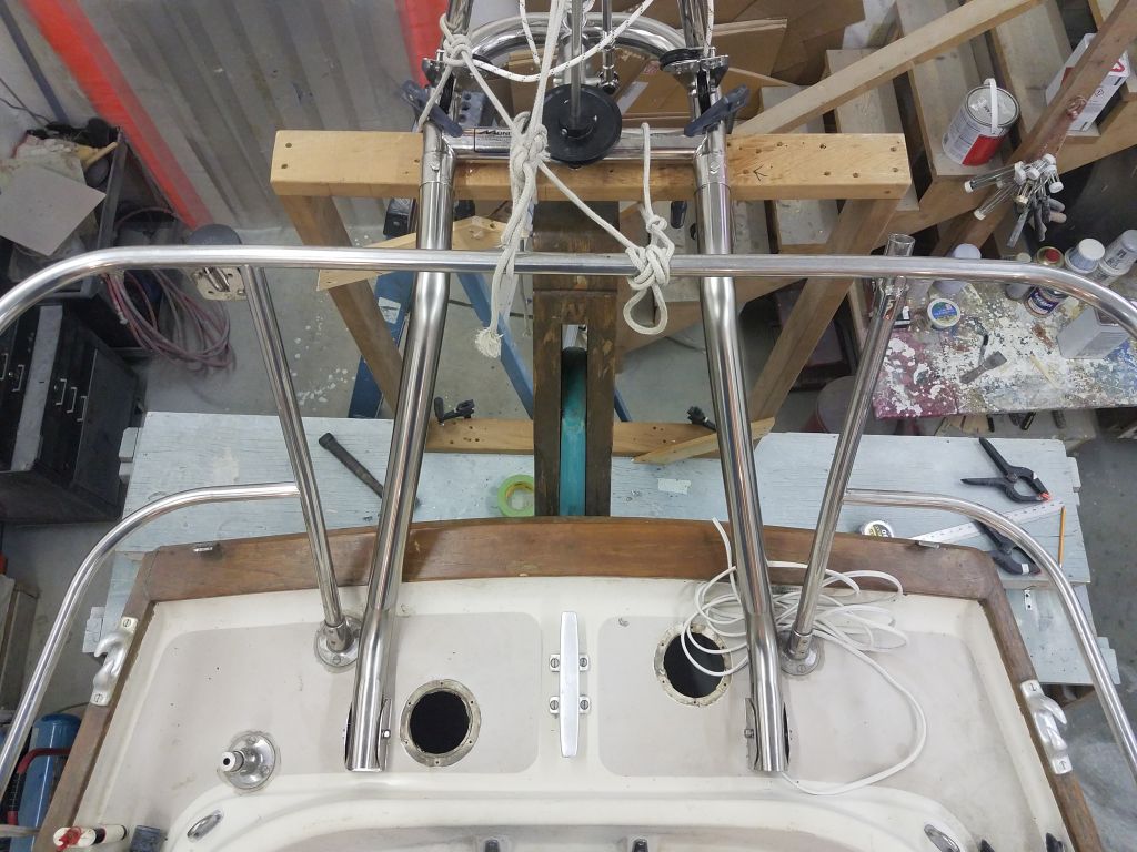
Now, after a final check of level and plumb, I could go around and tighten up all the bolts to finalize the installation, which made the whole thing incredibly stable and stiff and strong.

Total time billed on this job today:  7.5 Hours

0600 Weather Observation:  18°, snow, about an inch down so far.  Forecast for the day:  Light snow, maybe a few inches, becoming showery and warmer in the afternoon

Older posts