(page 86 of 167)

Scupper 240

Wednesday

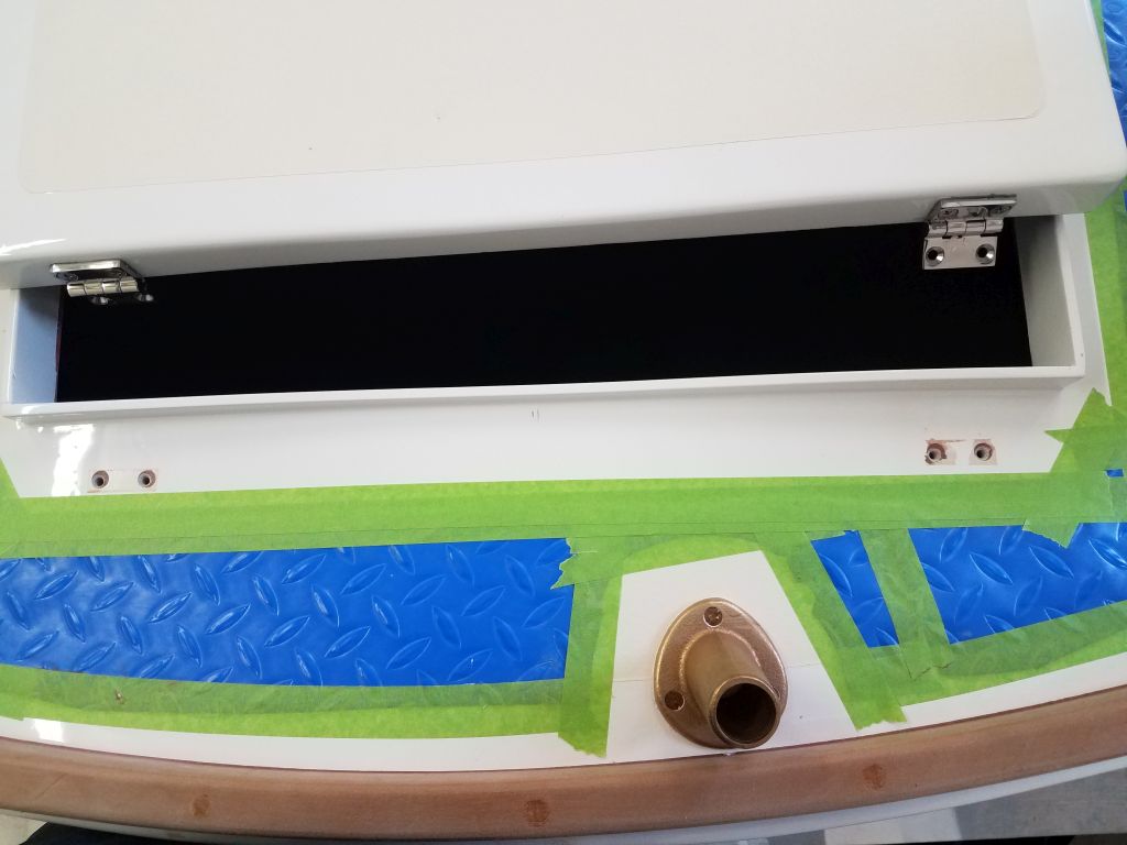
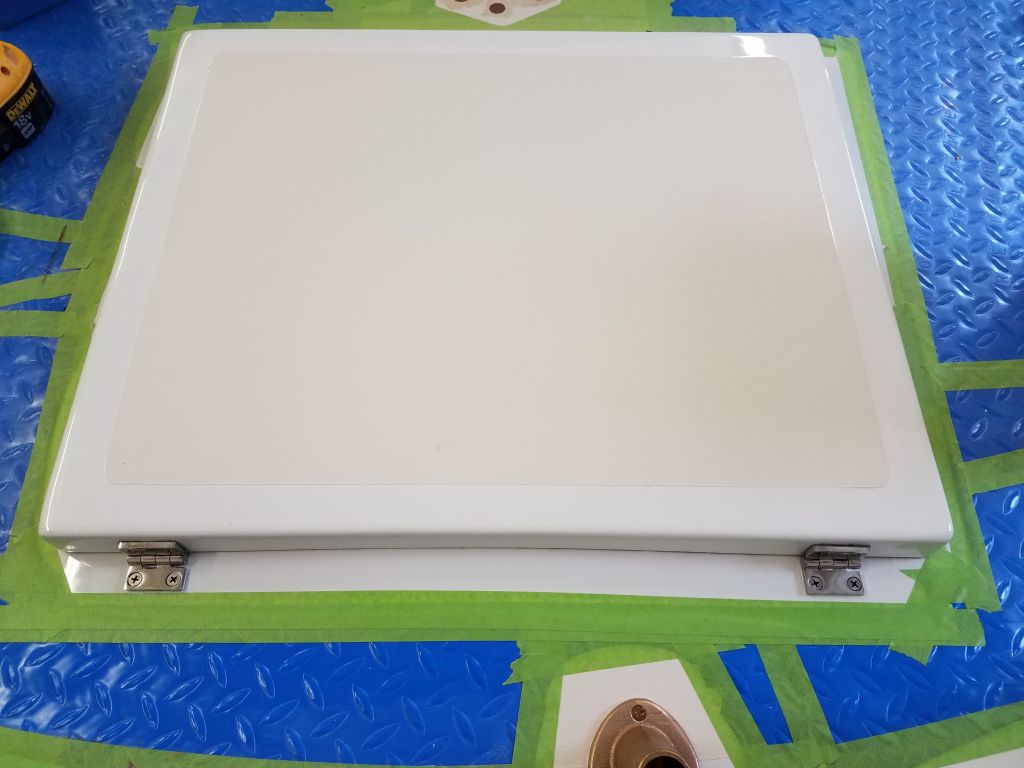
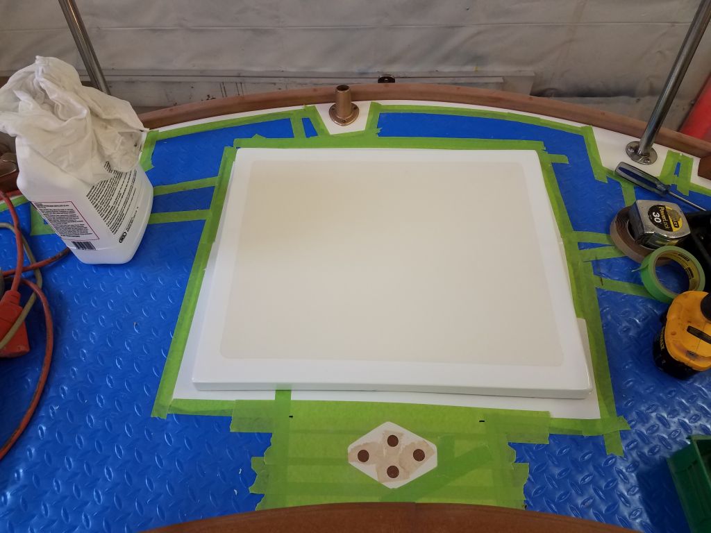
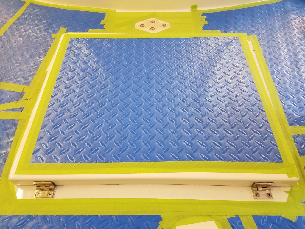
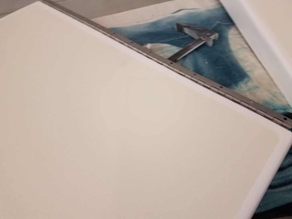
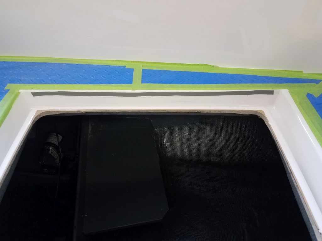
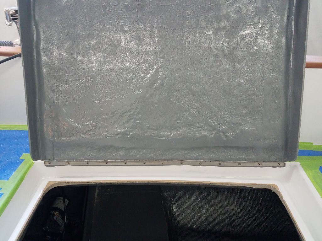
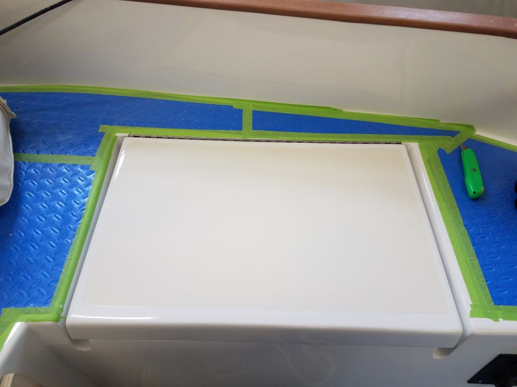
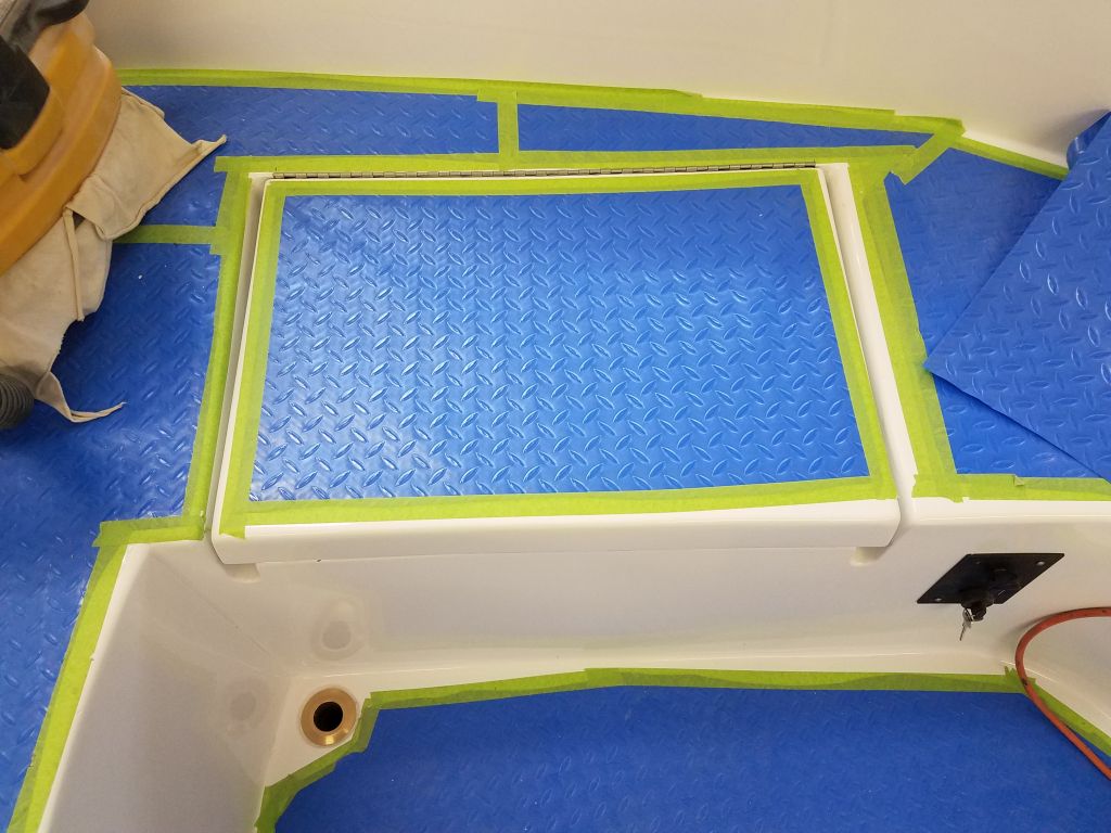
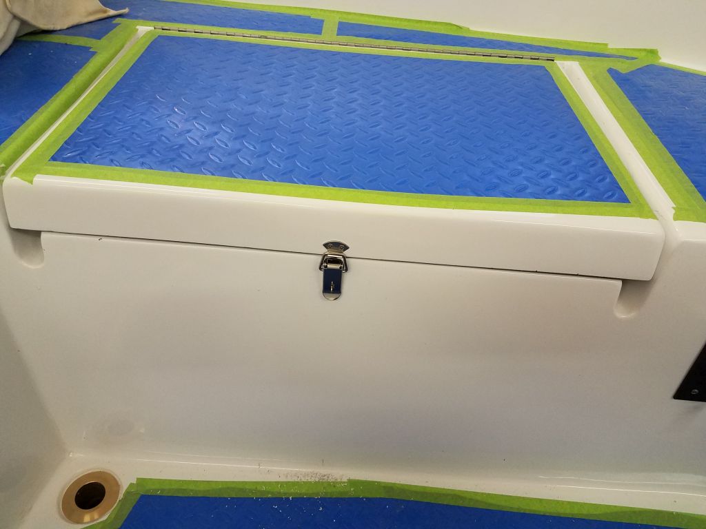
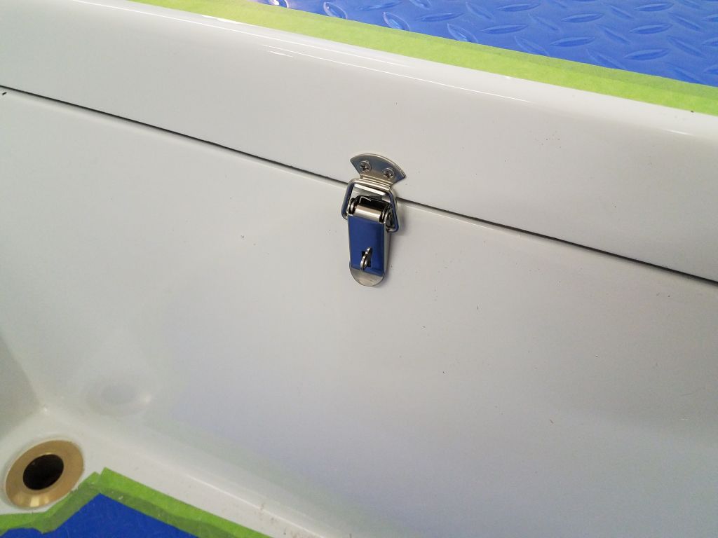
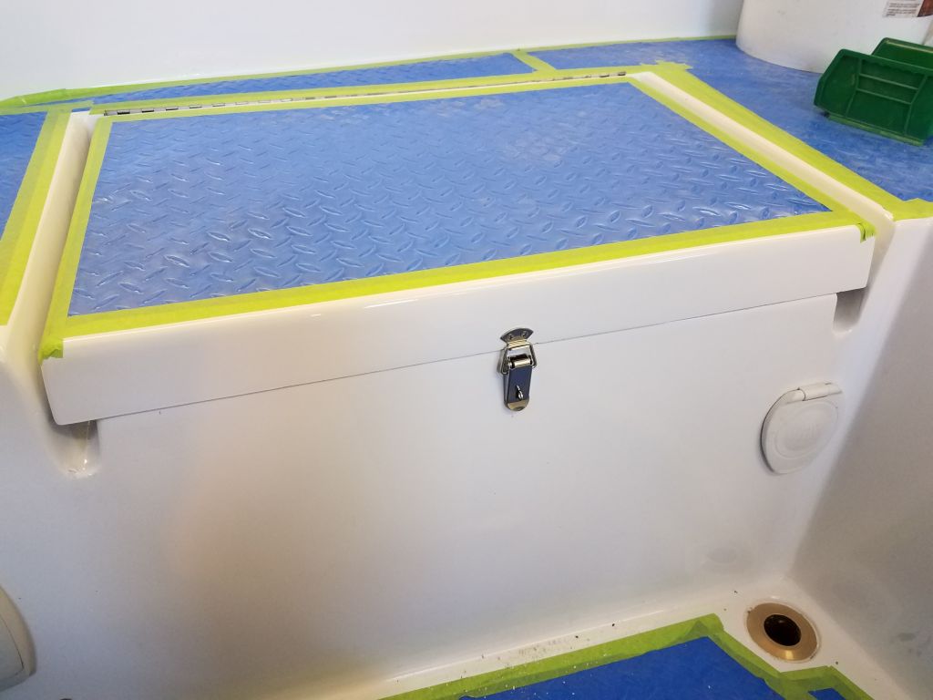
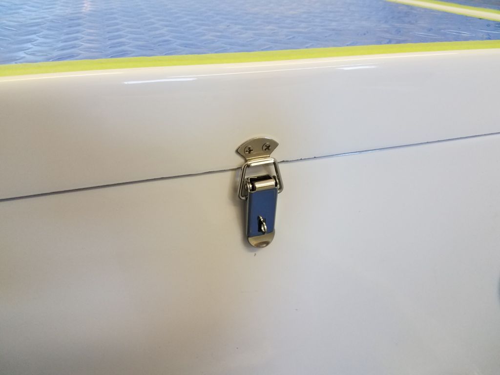
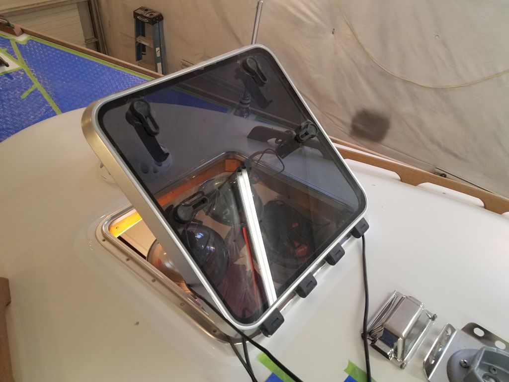
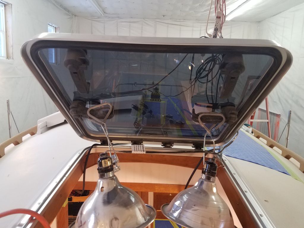
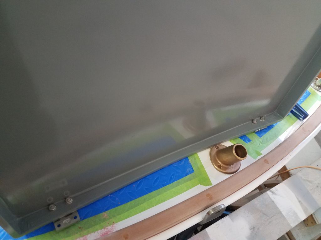
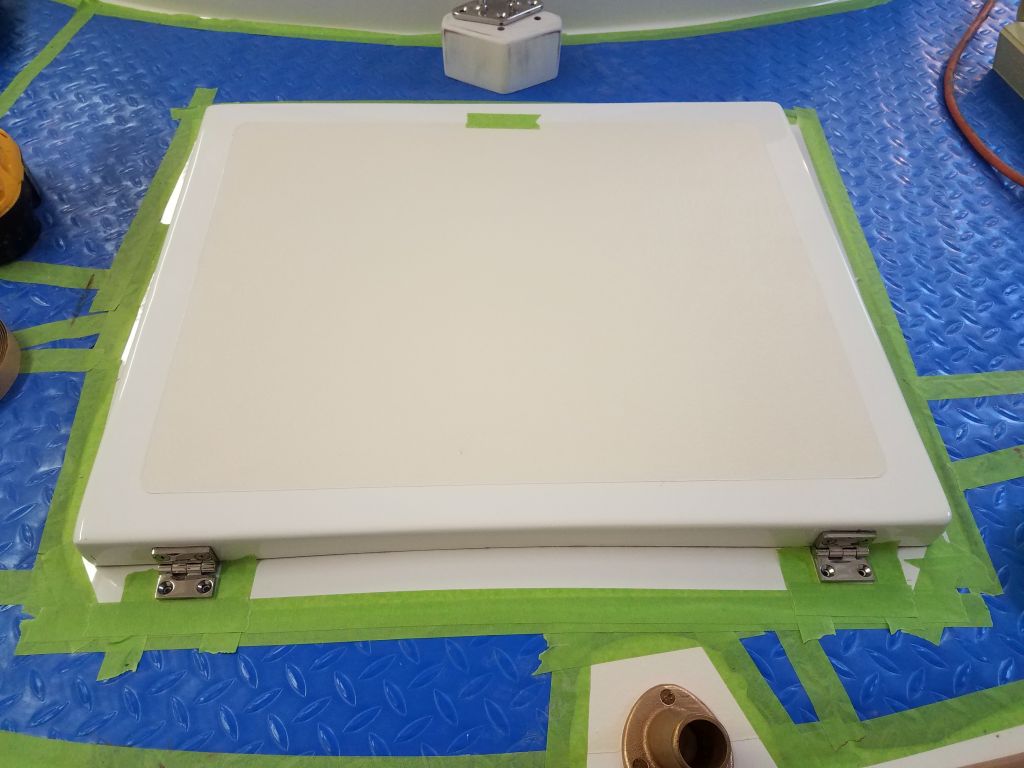
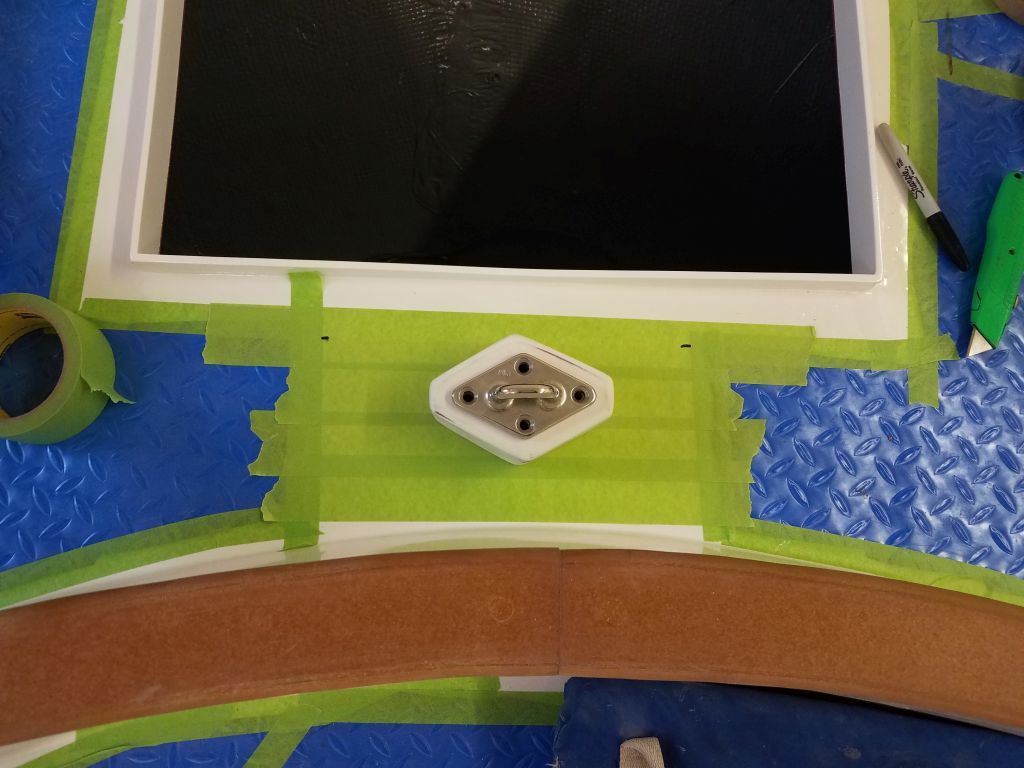
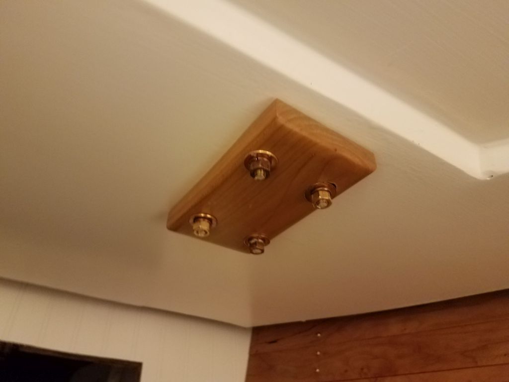
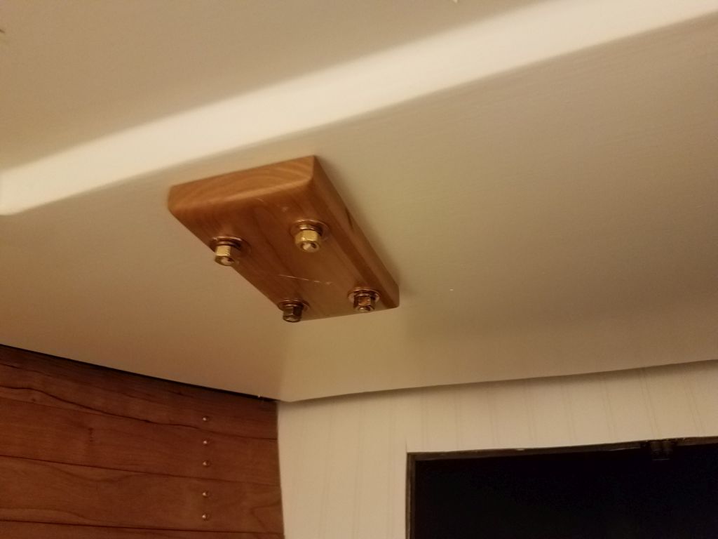
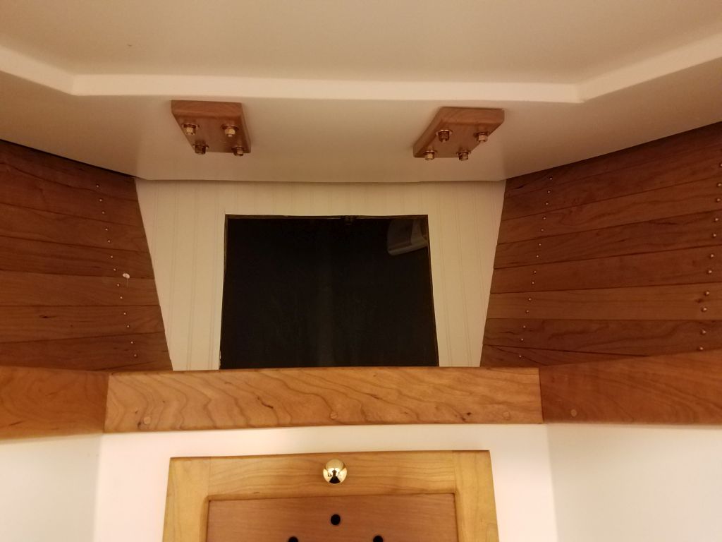
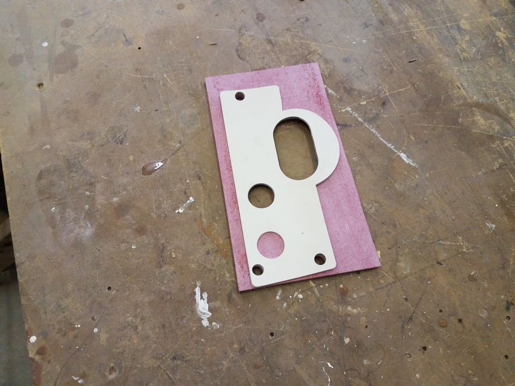
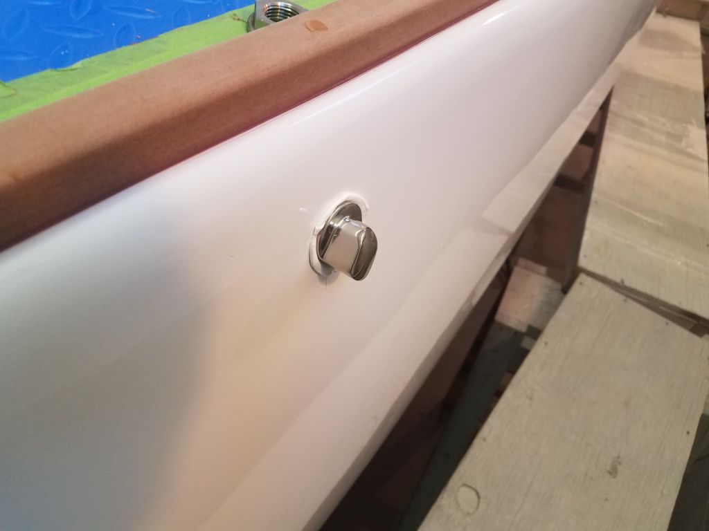
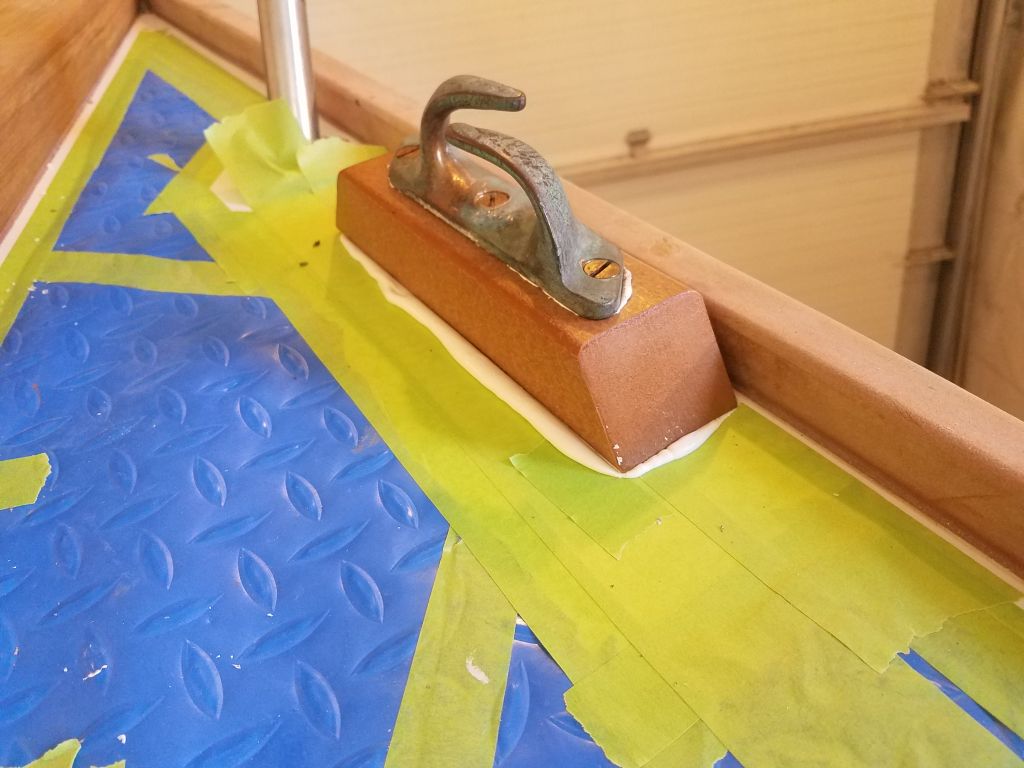
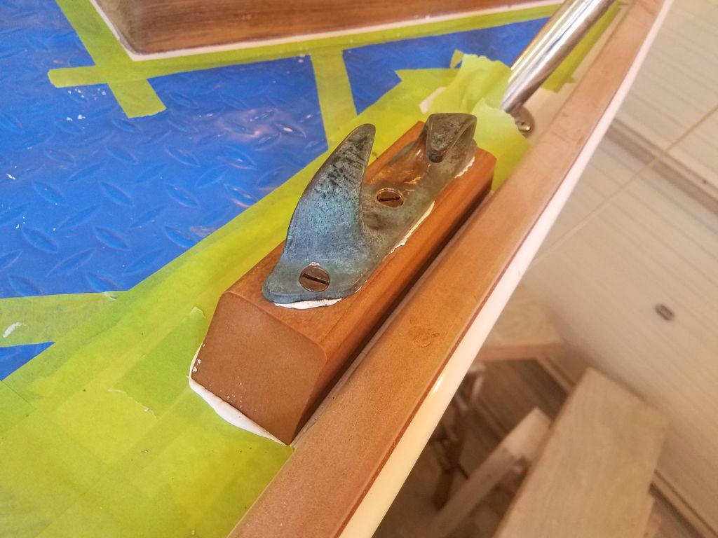
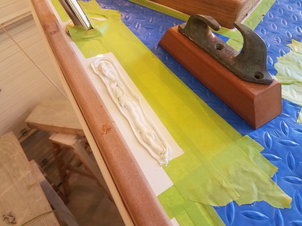
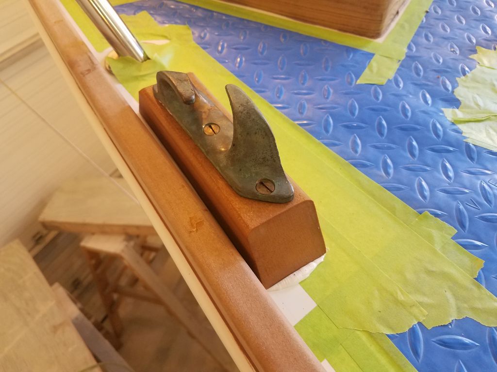
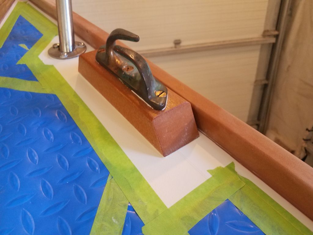
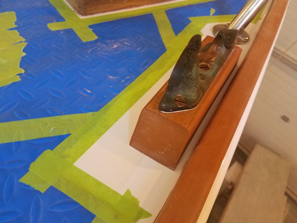
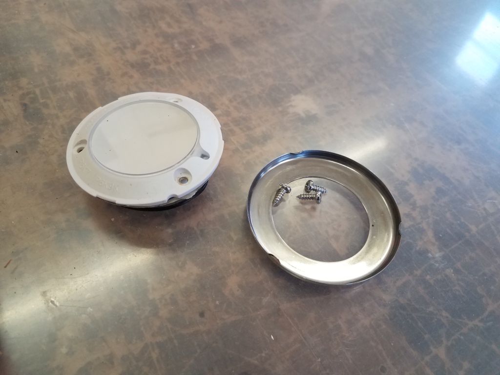
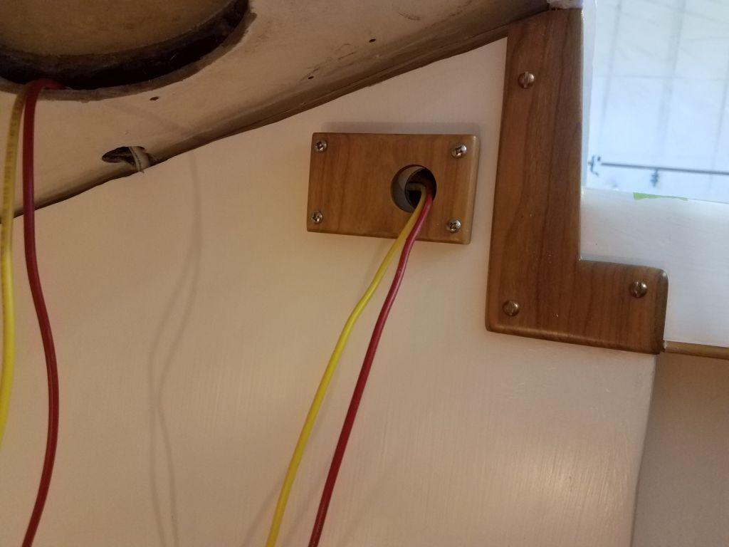
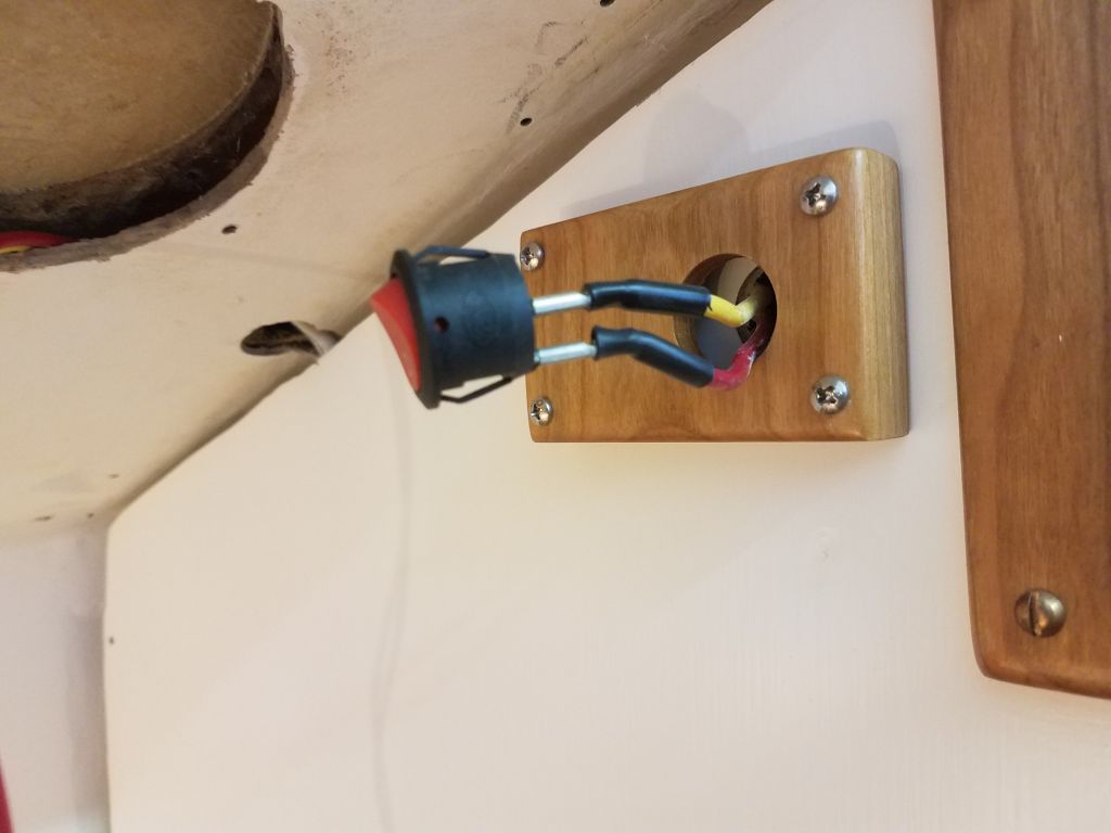
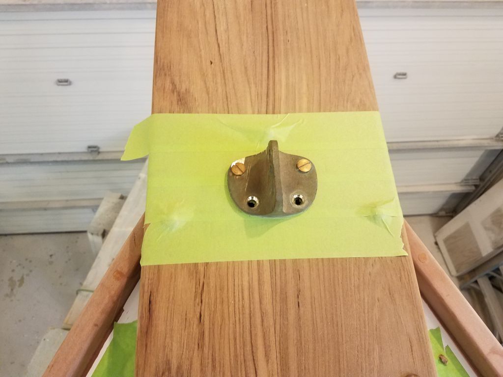
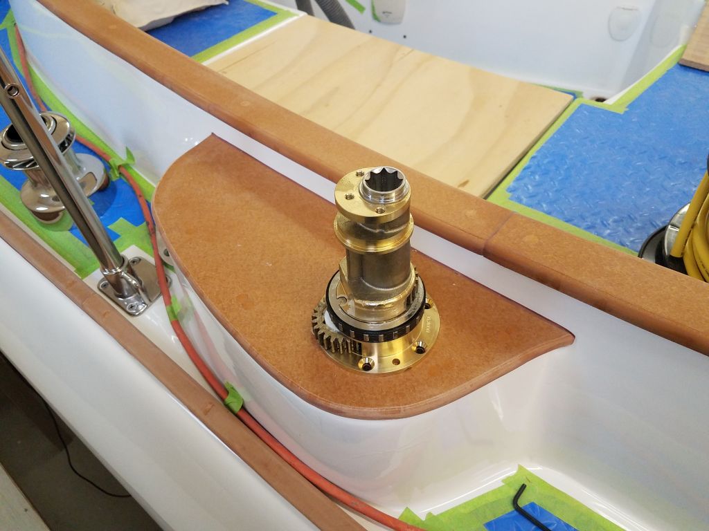
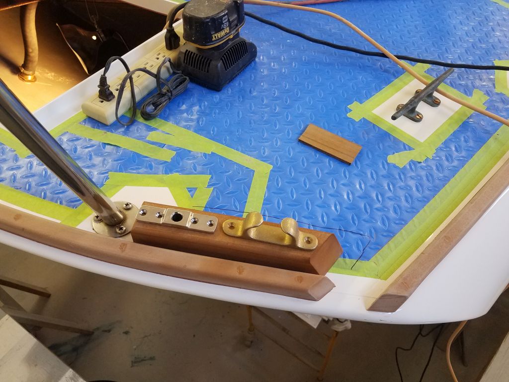
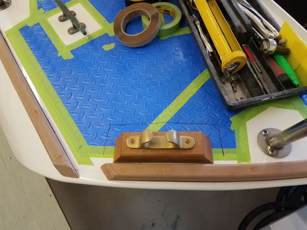
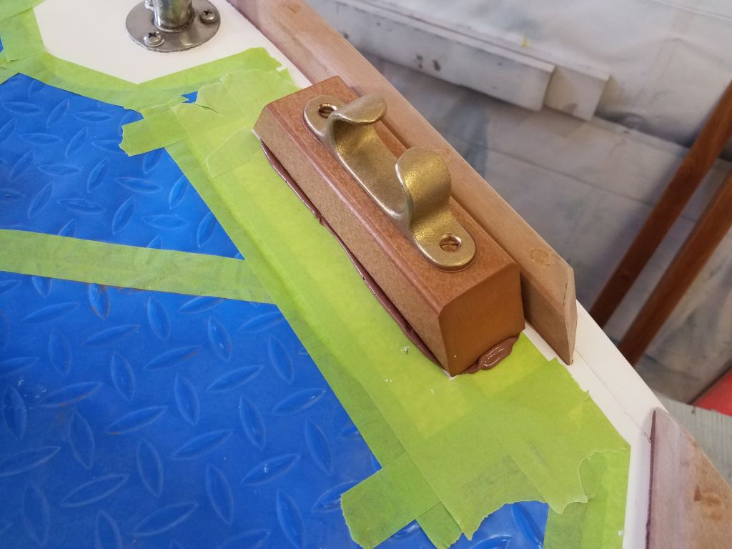
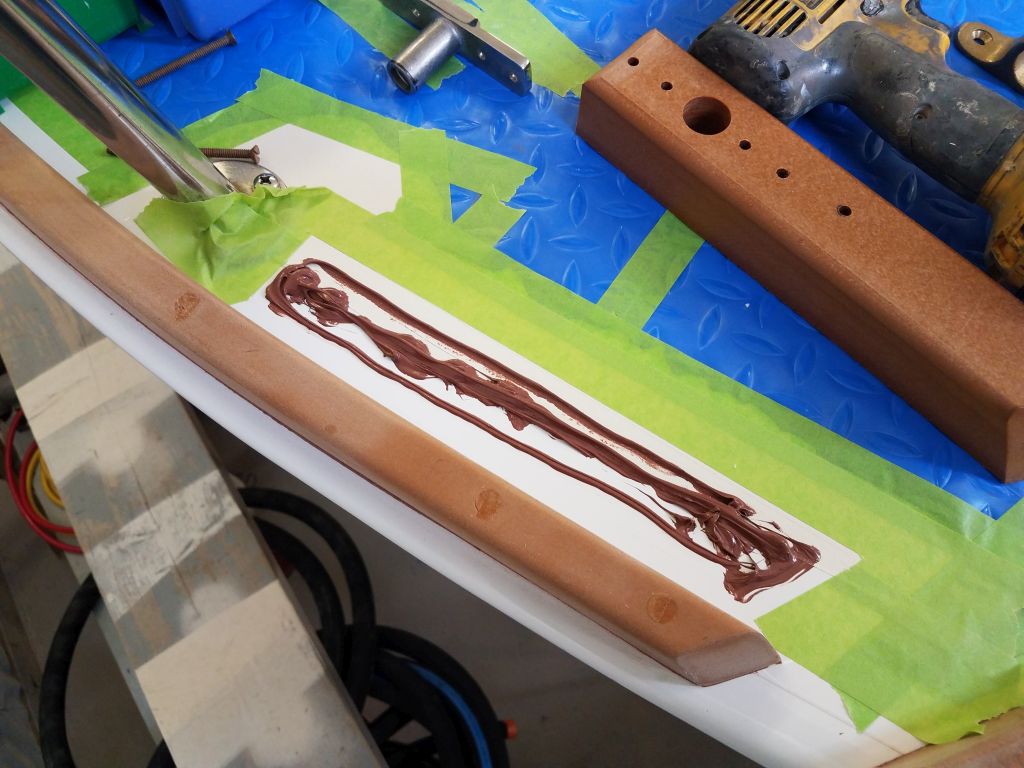
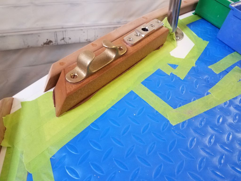
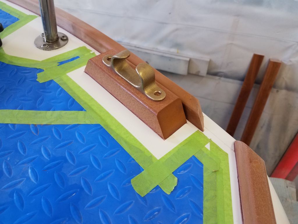
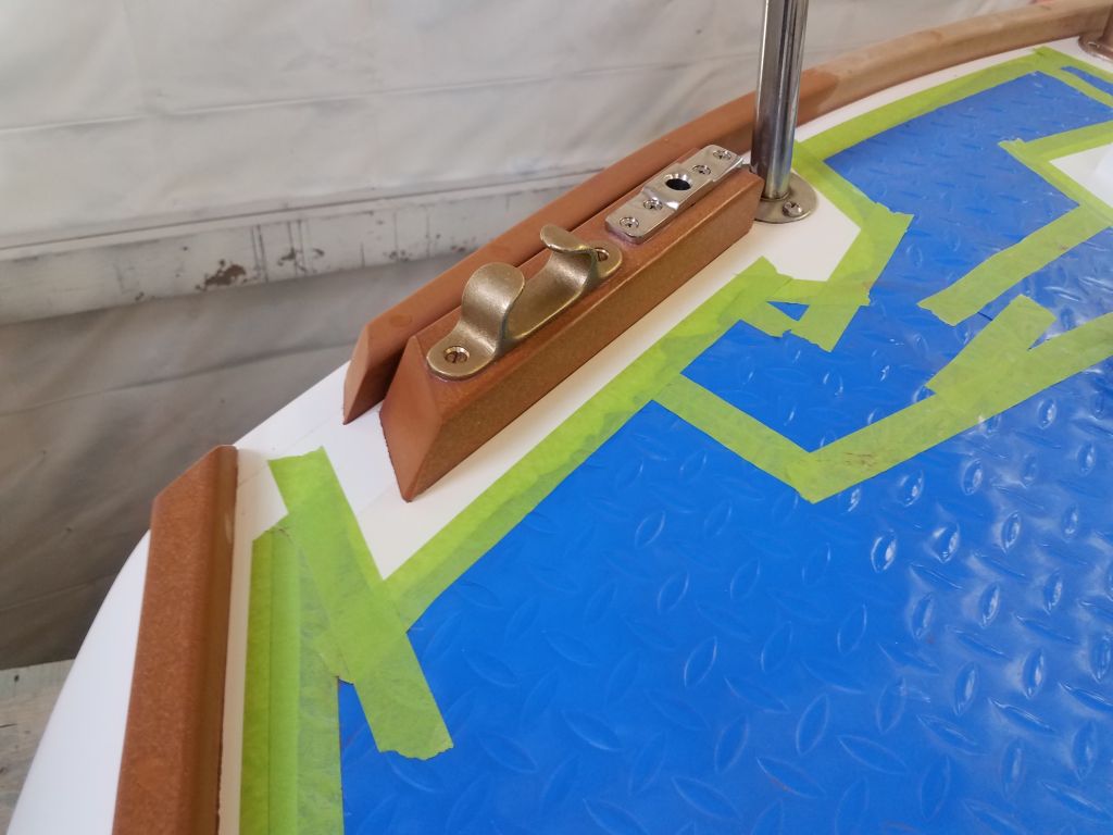
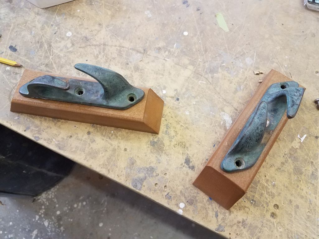
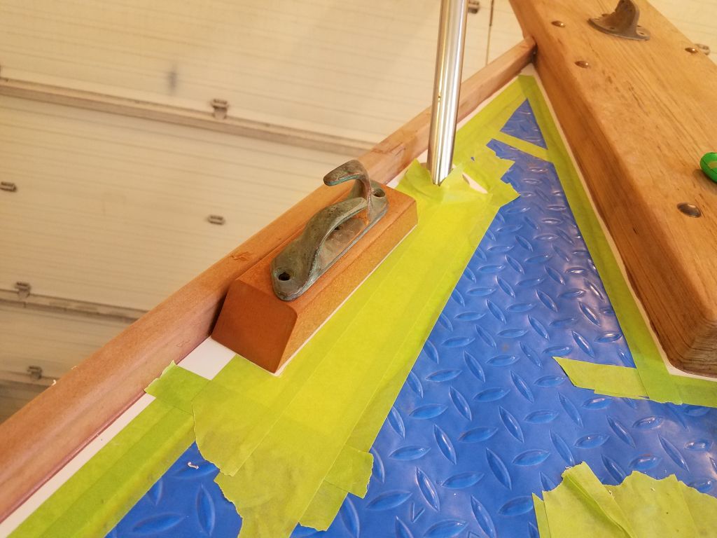
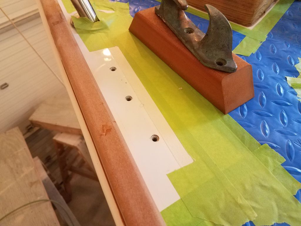
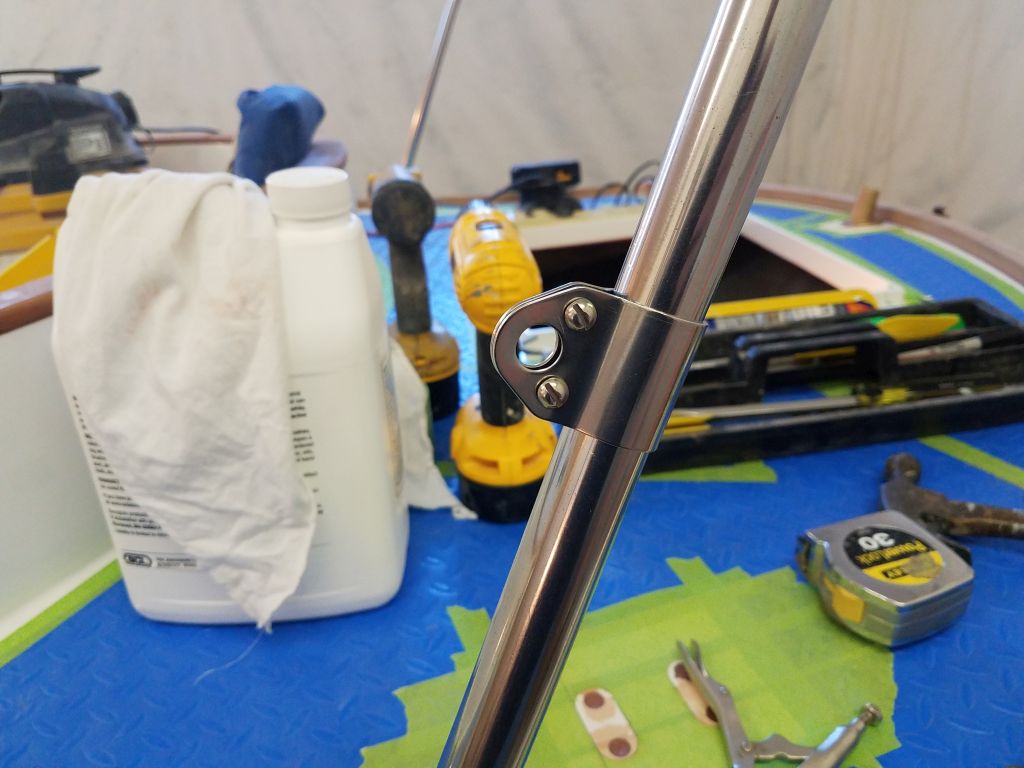
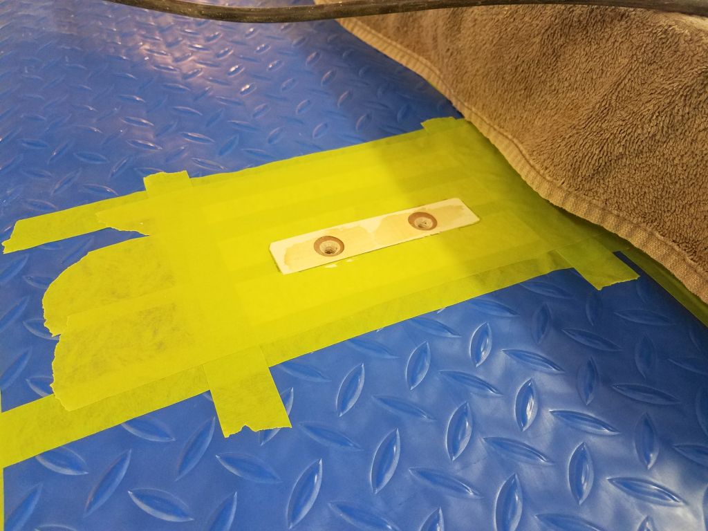
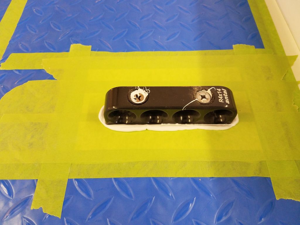
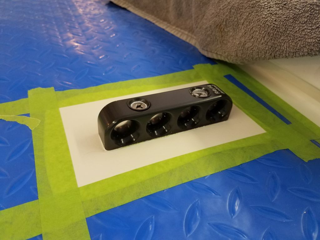
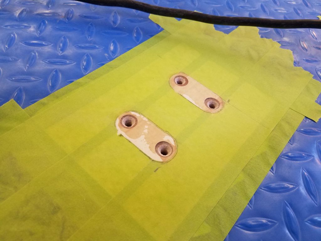
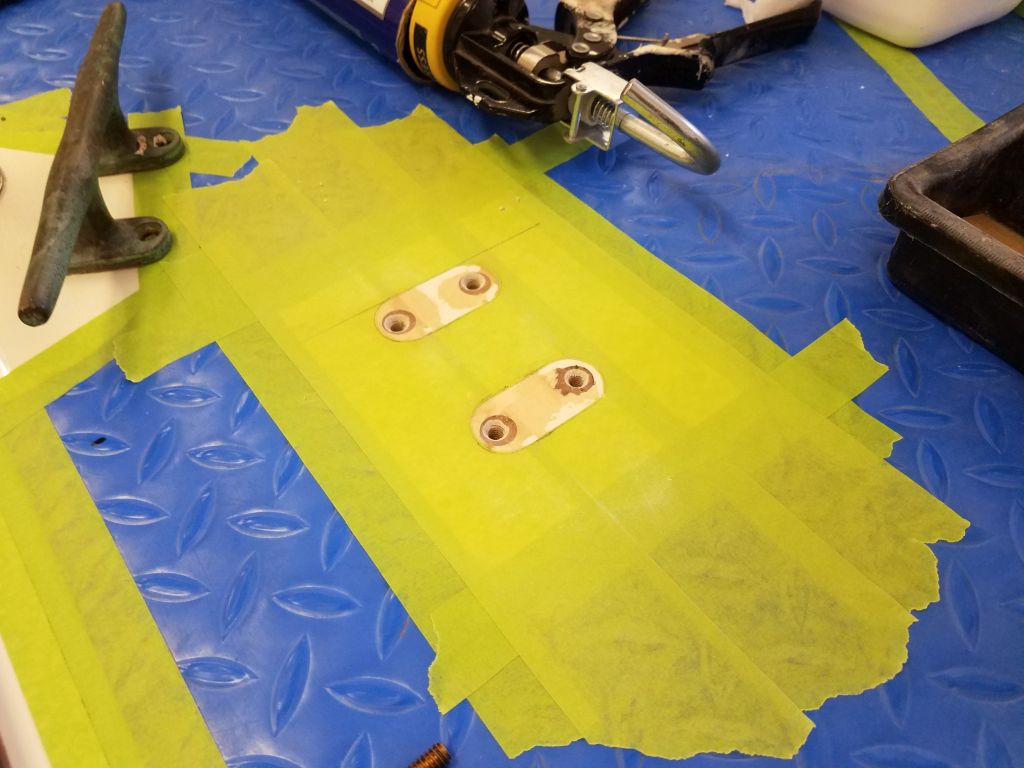
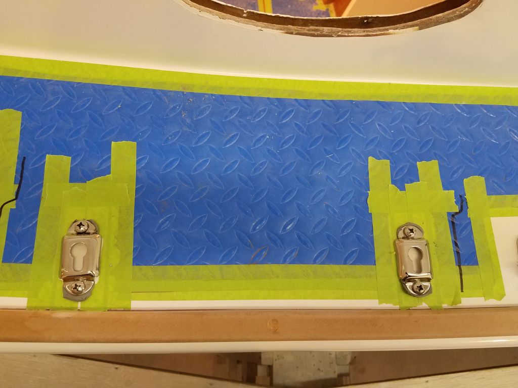
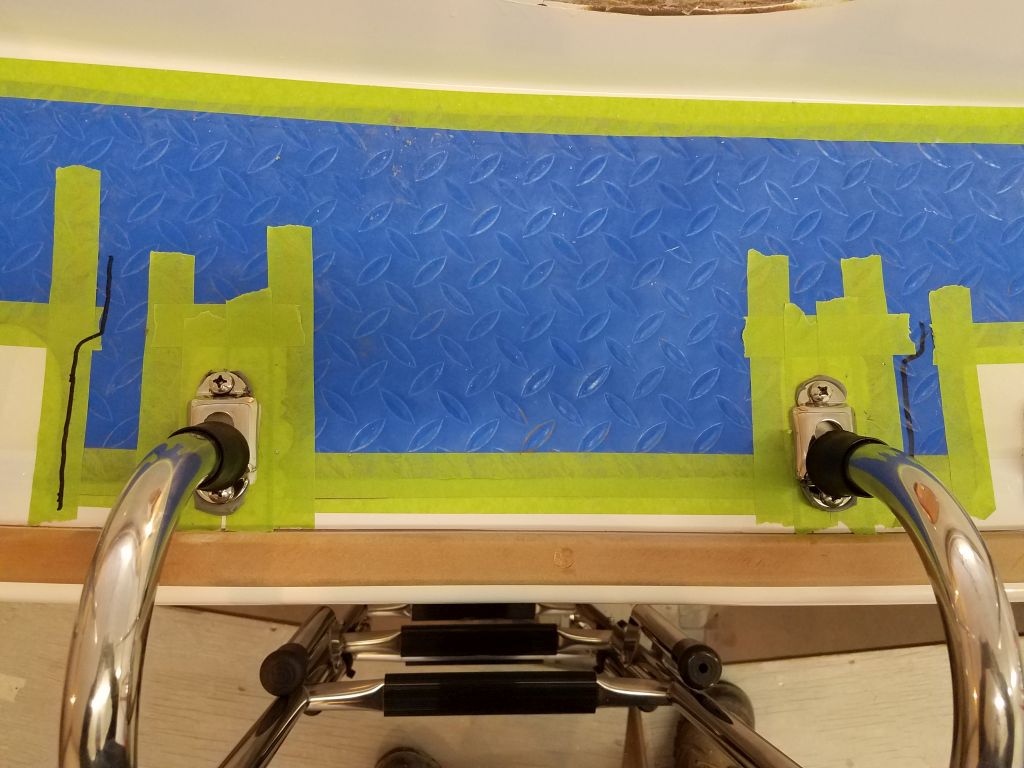
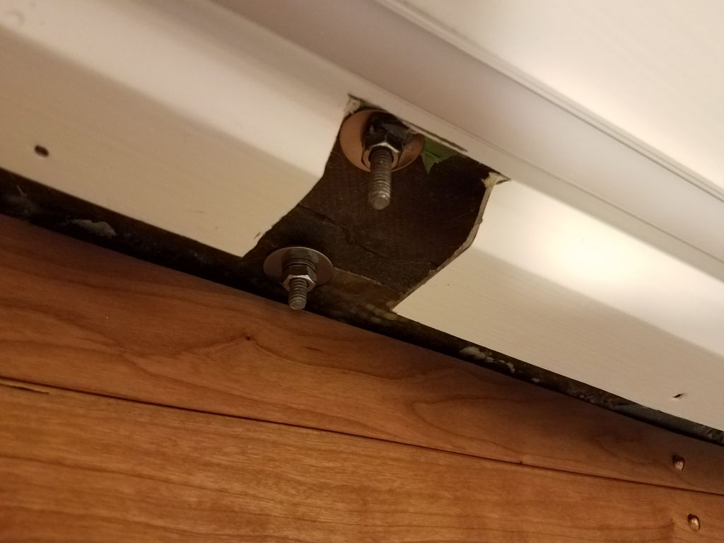
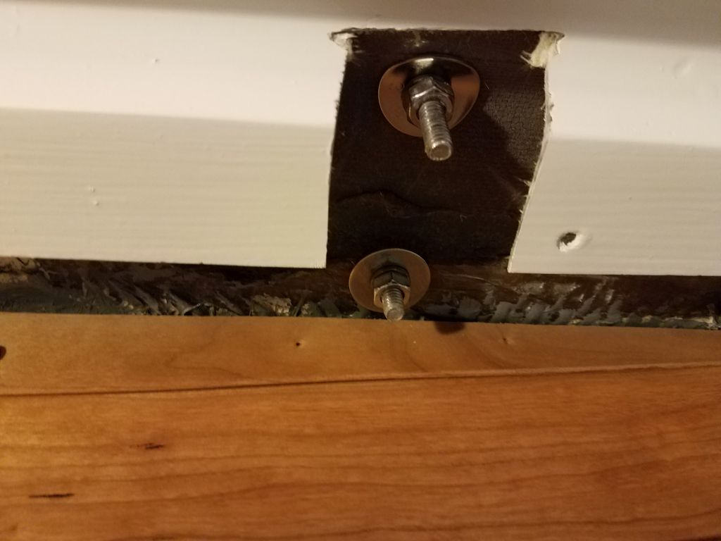
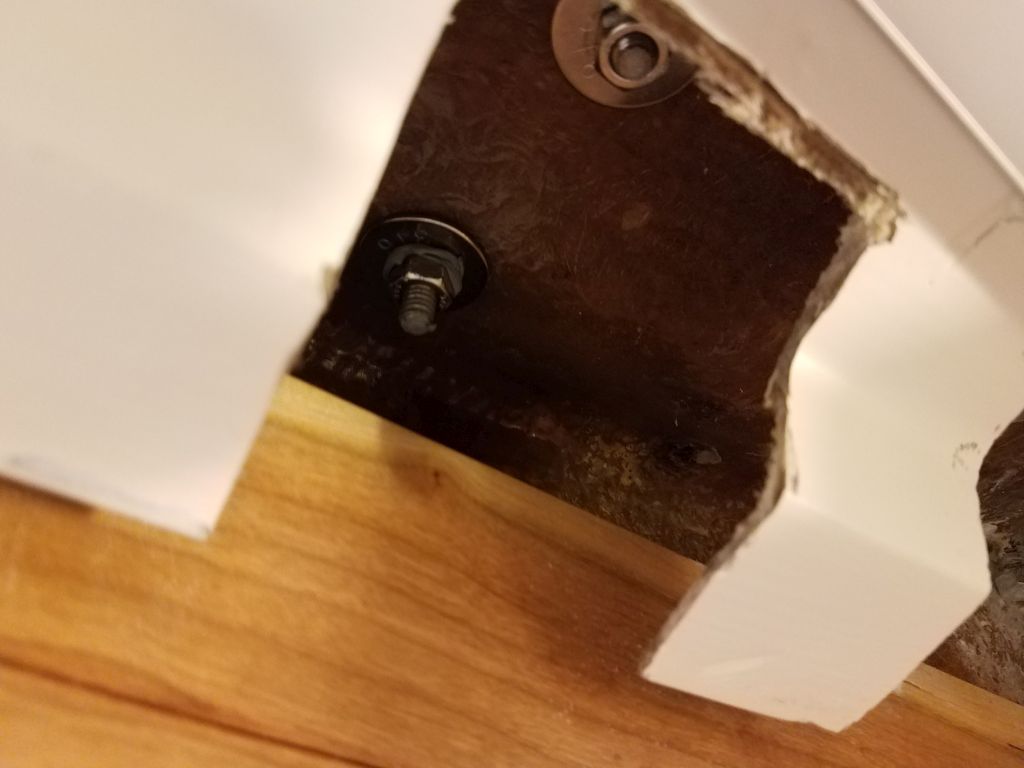
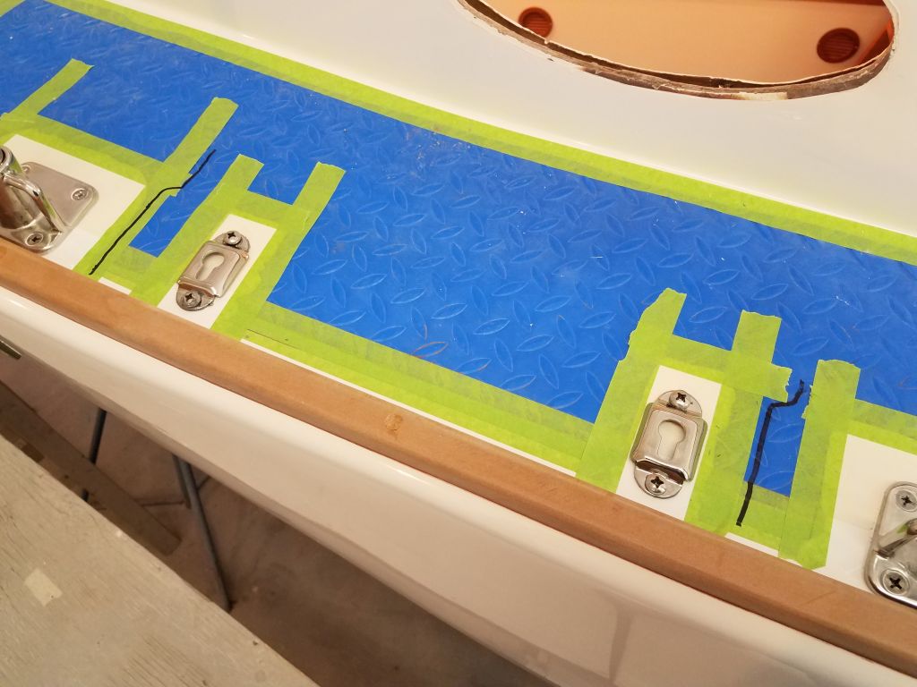
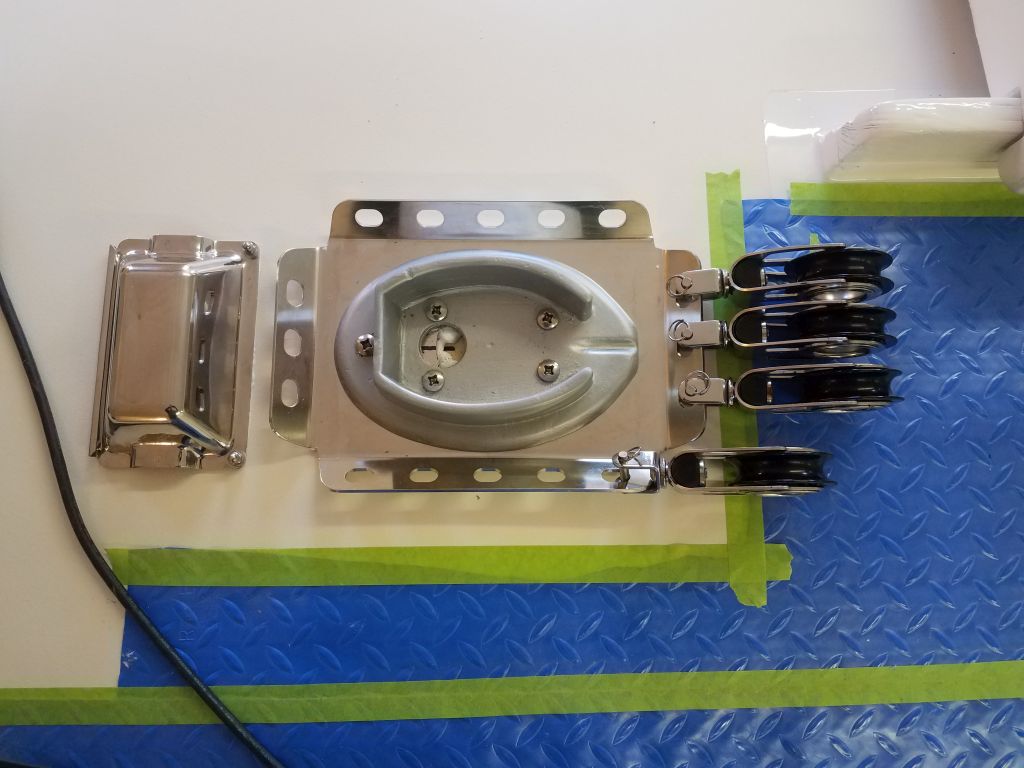
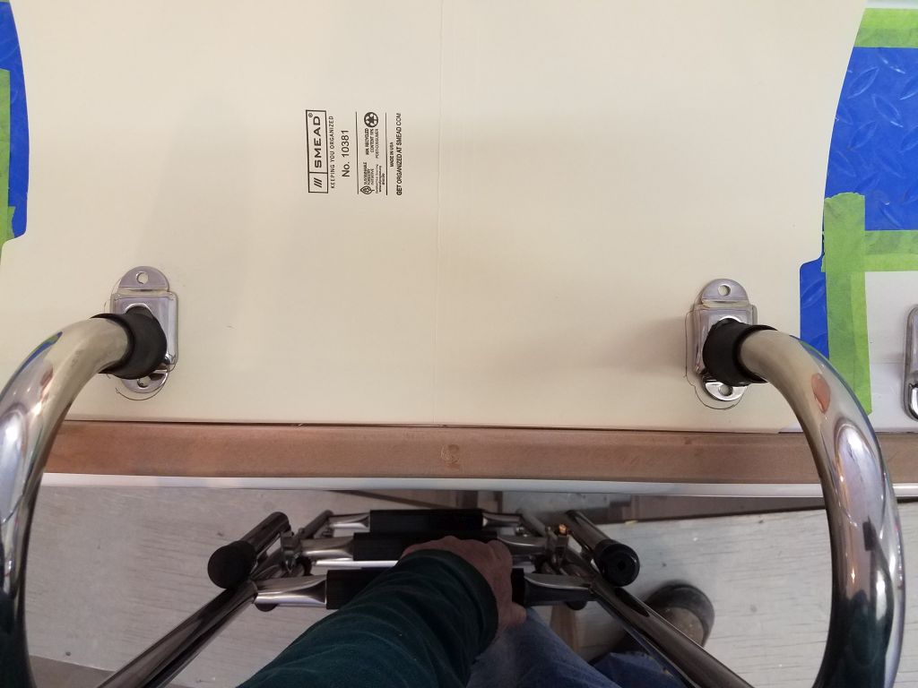
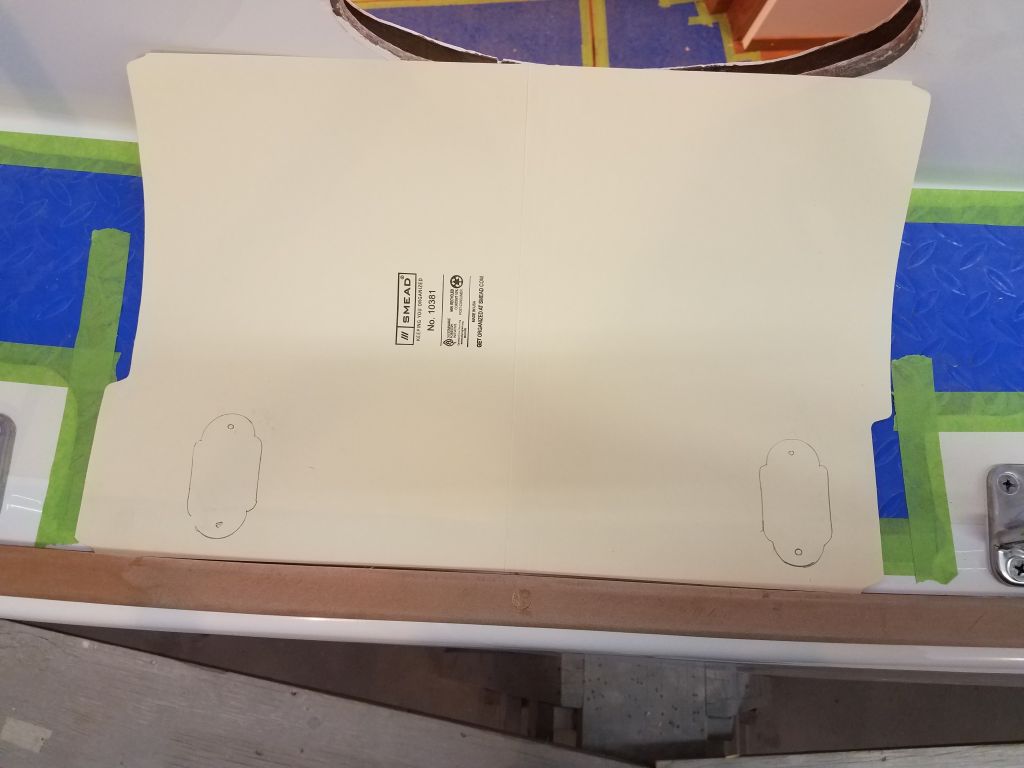
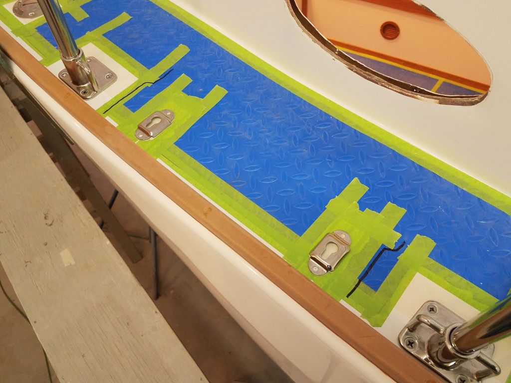
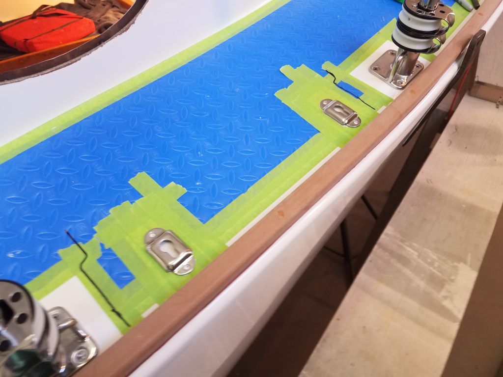
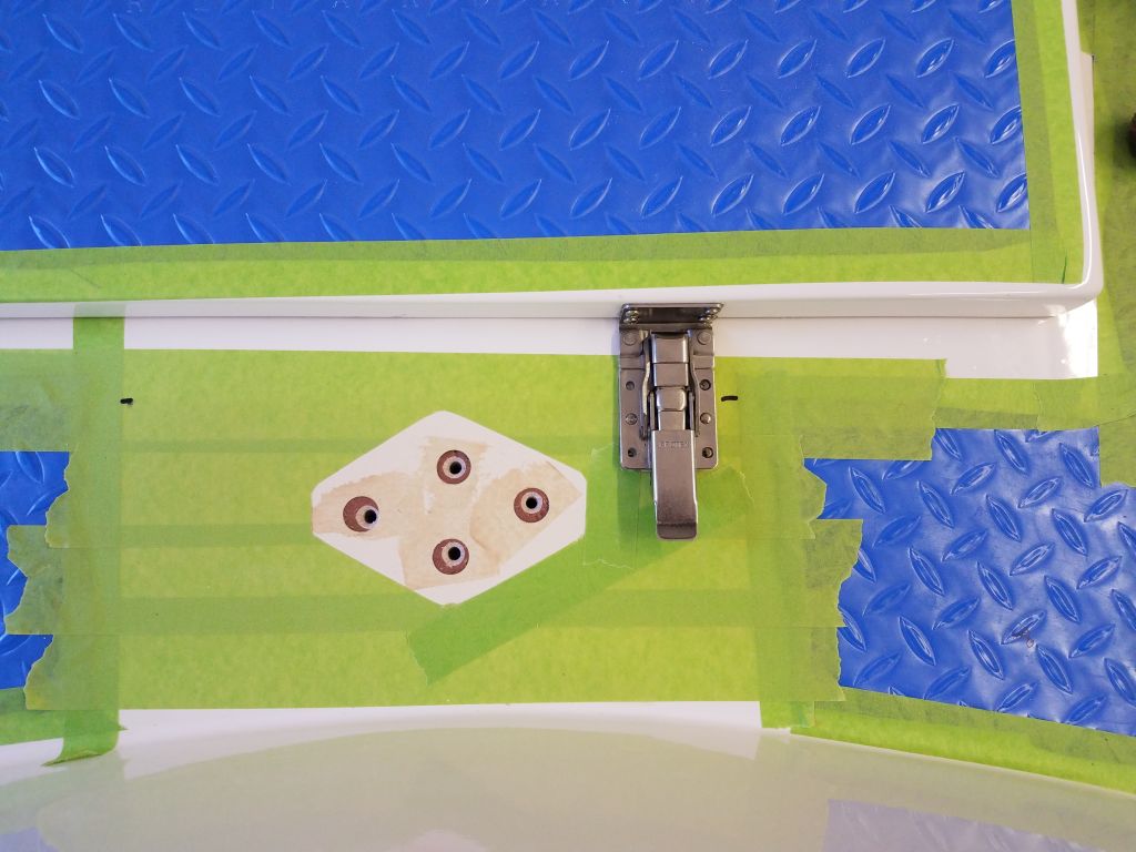
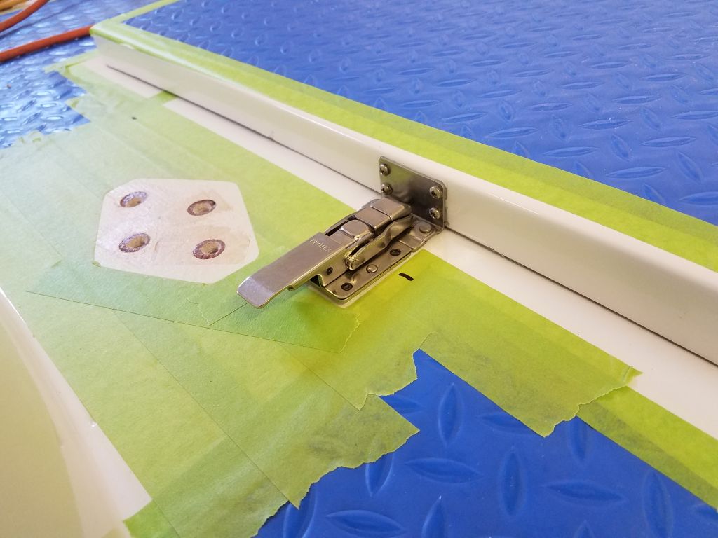
The slim height of the lazarette hatch required  a specific sort of latch, one that could work in the narrow inside corner formed by the hatch and the adjacent deck, securing the hatch in place as well as providing a means of locking.  I obtained just such a latch, and now went through the usual motions of installation, beginning with the hatch-mounted side of the latch, which I screwed directly to the forward side of the new hatch with four machine screws and sealant.

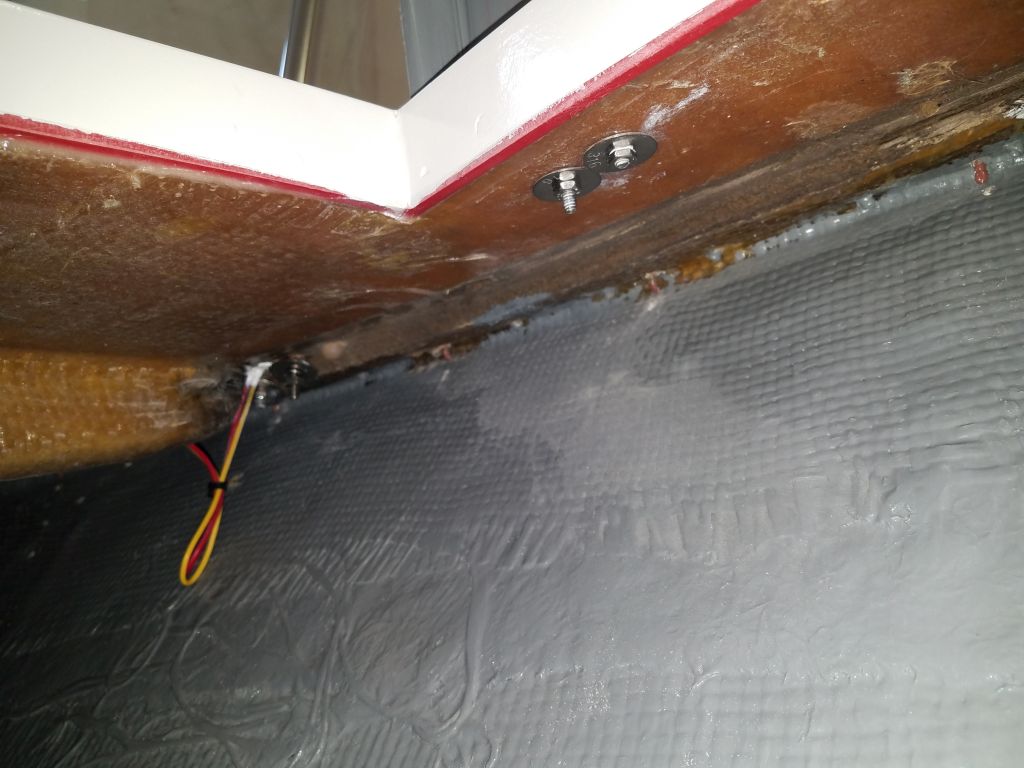
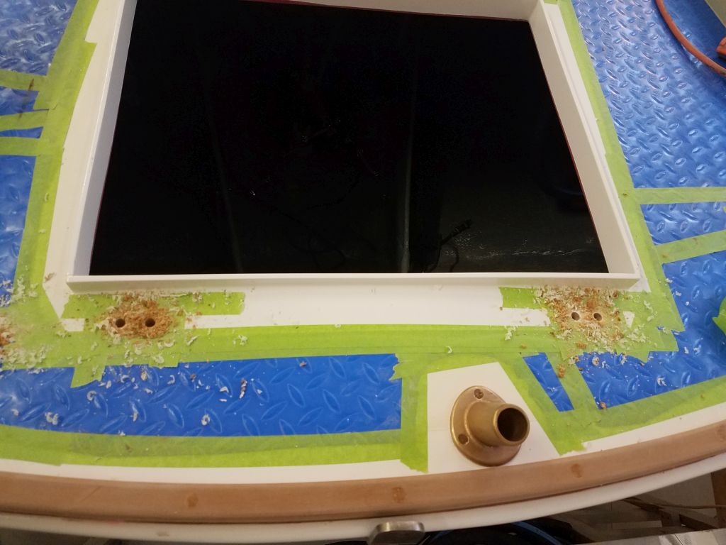
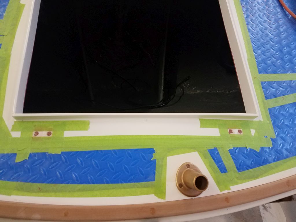
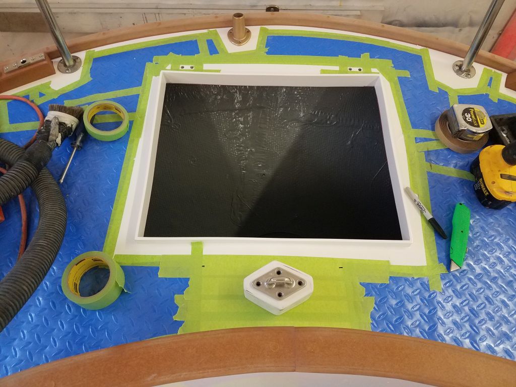
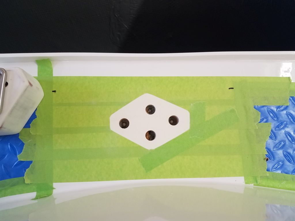
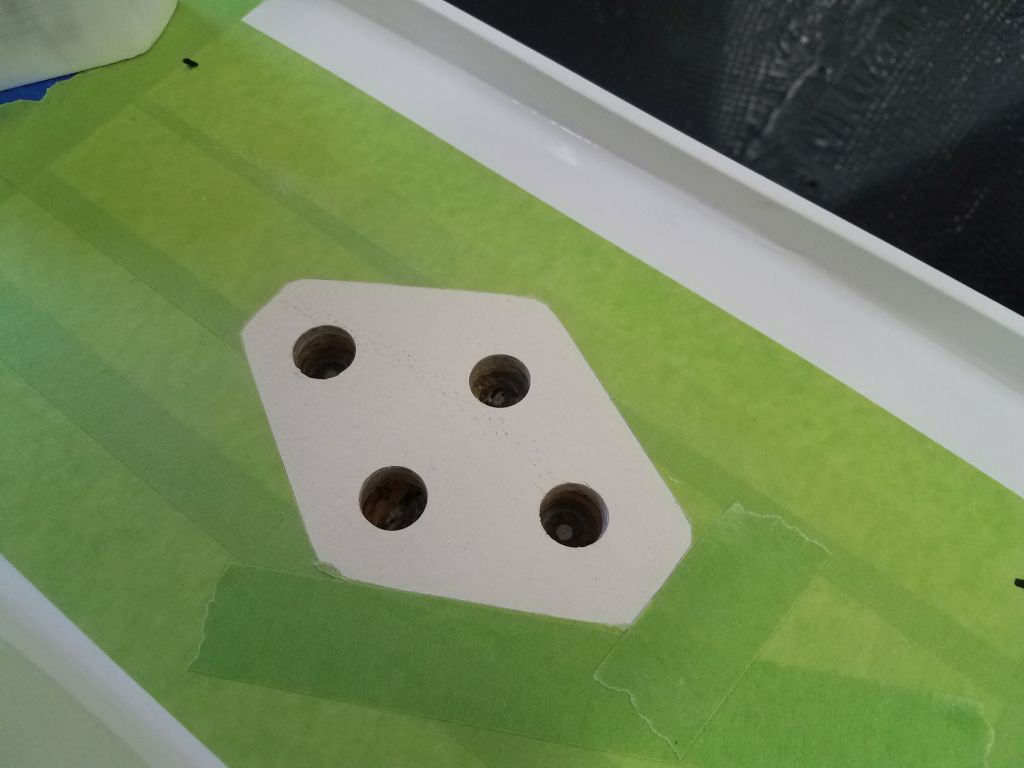
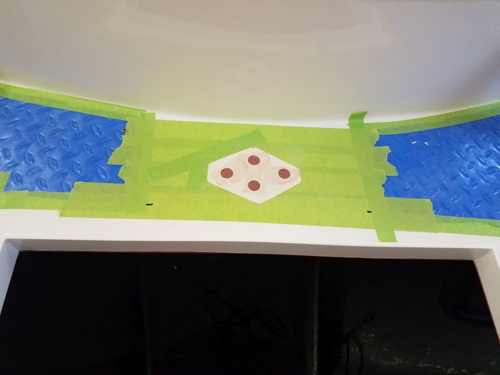
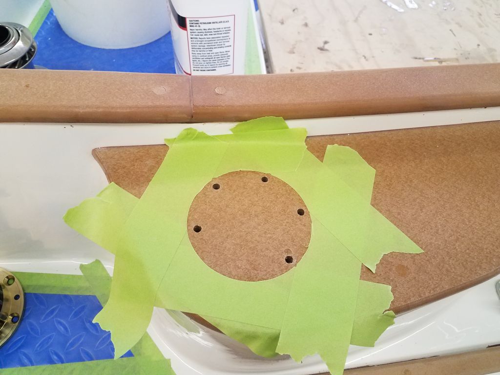
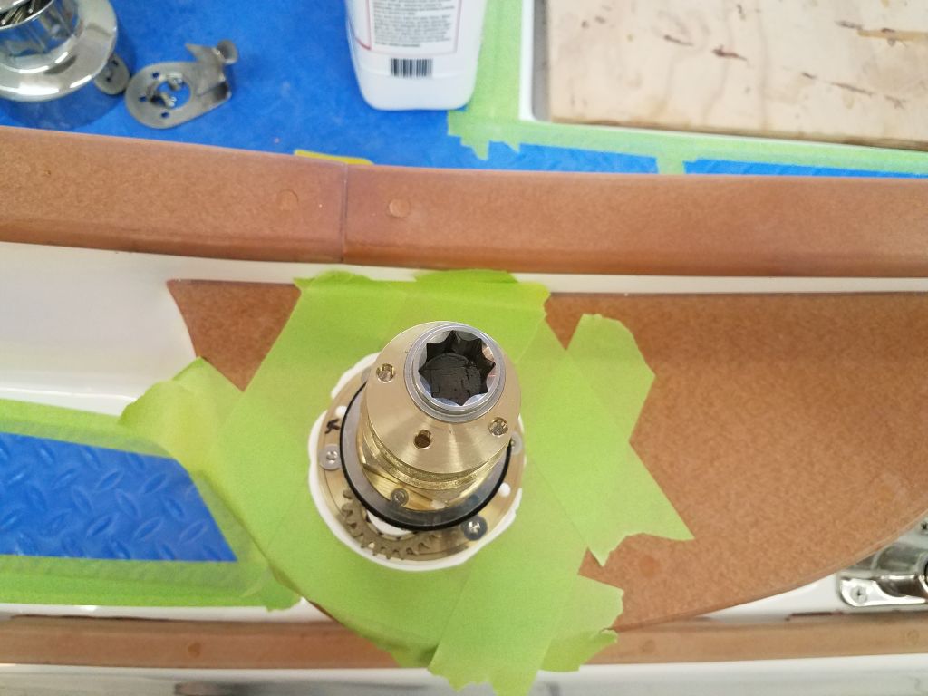
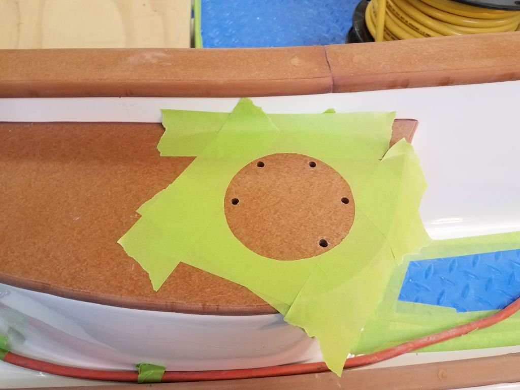
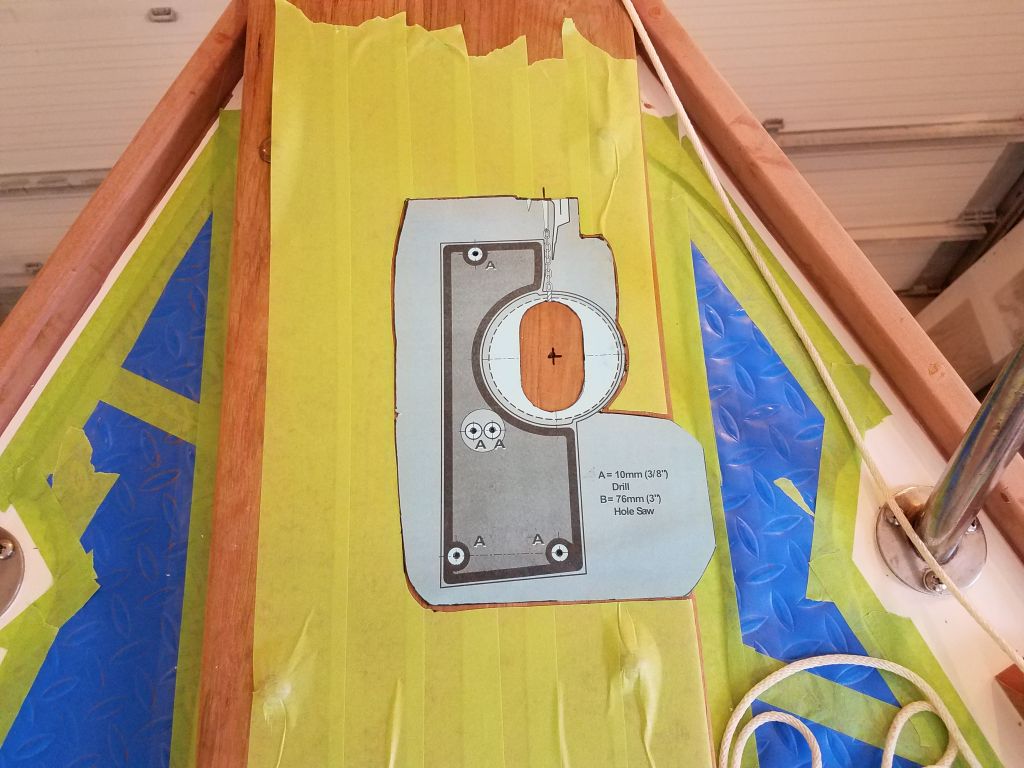
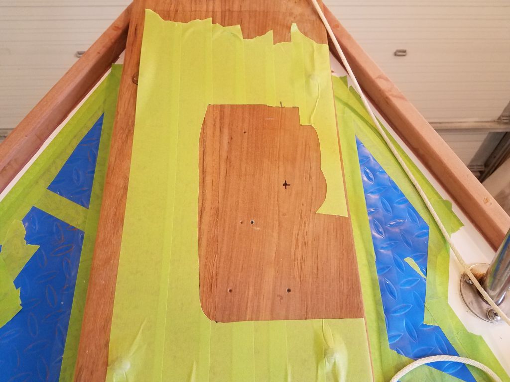
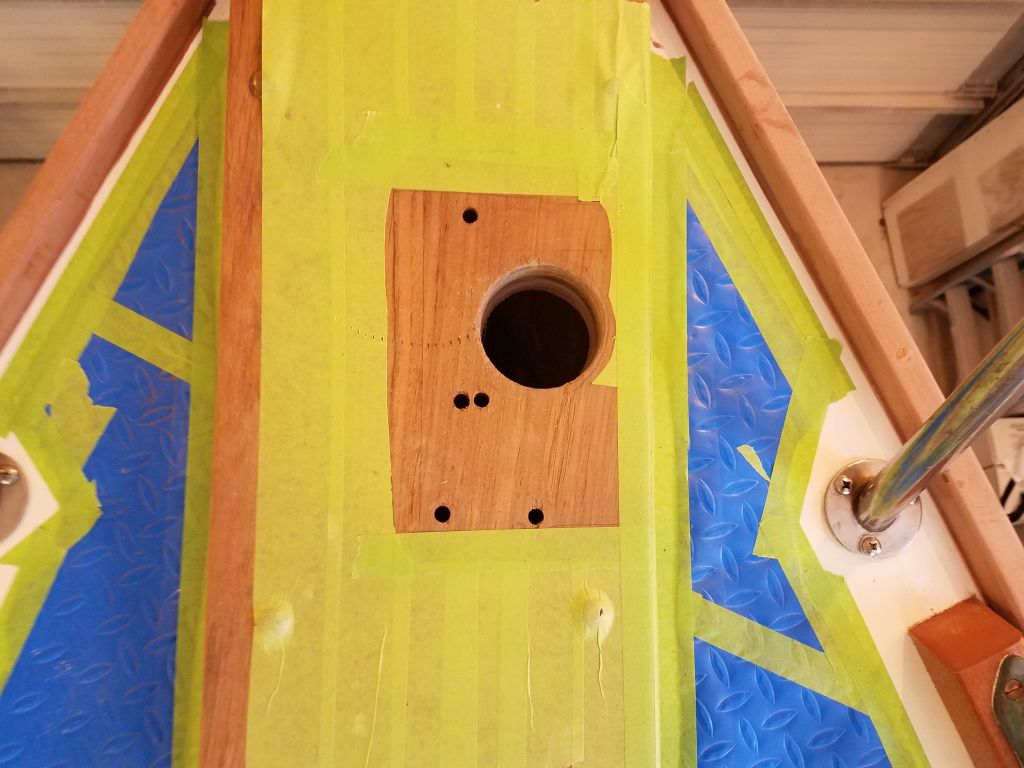
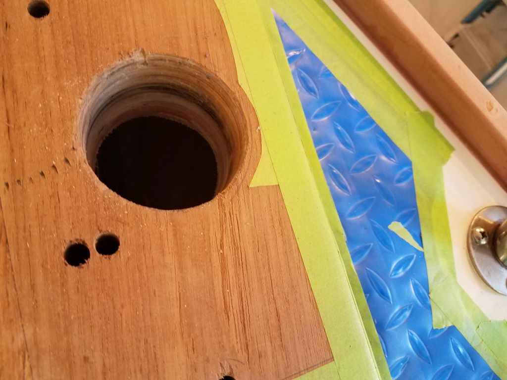
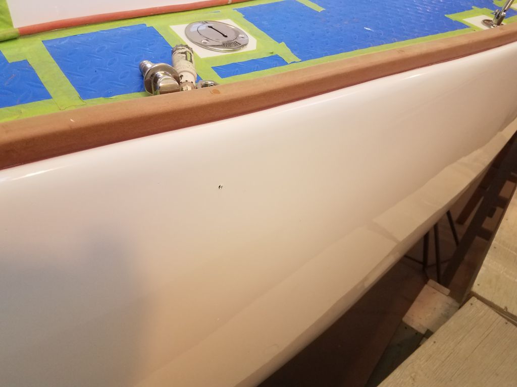
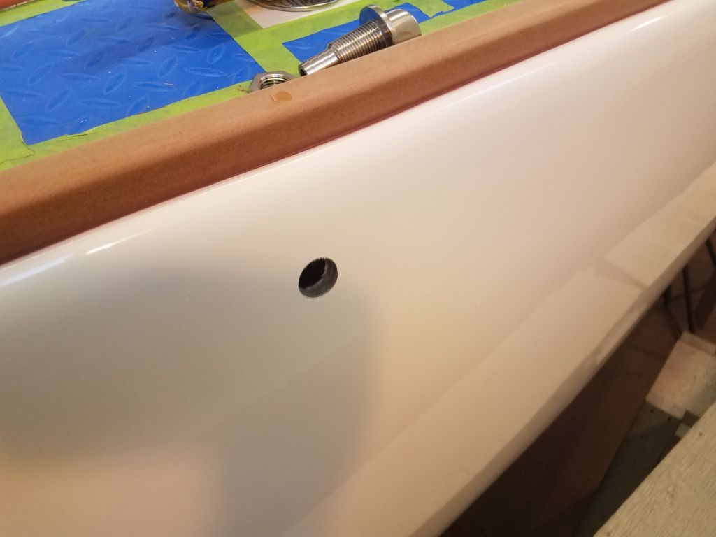
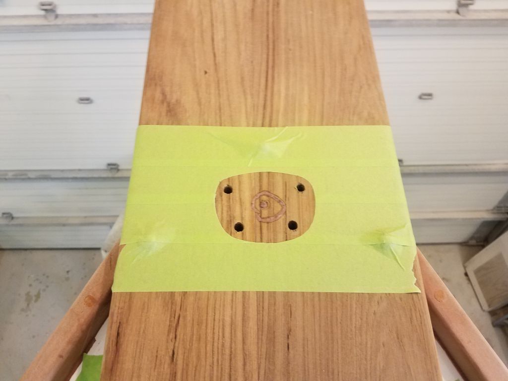
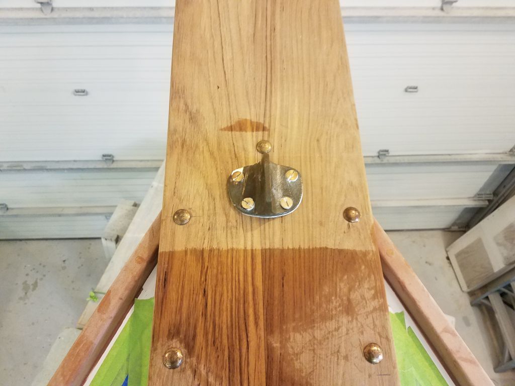
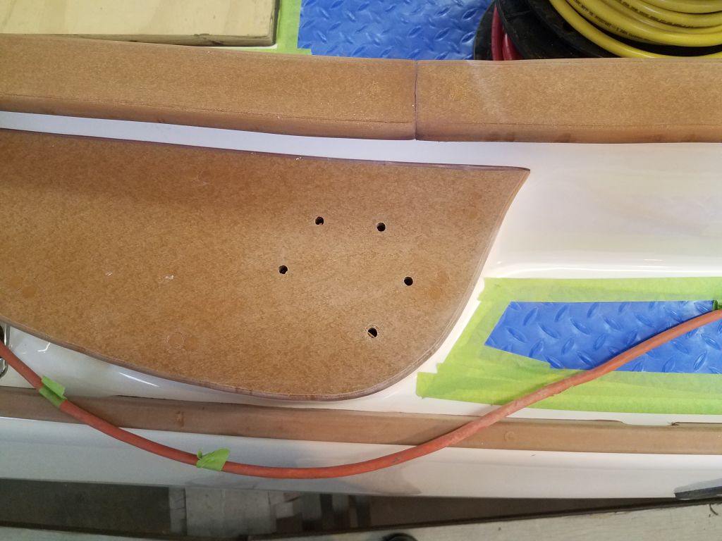
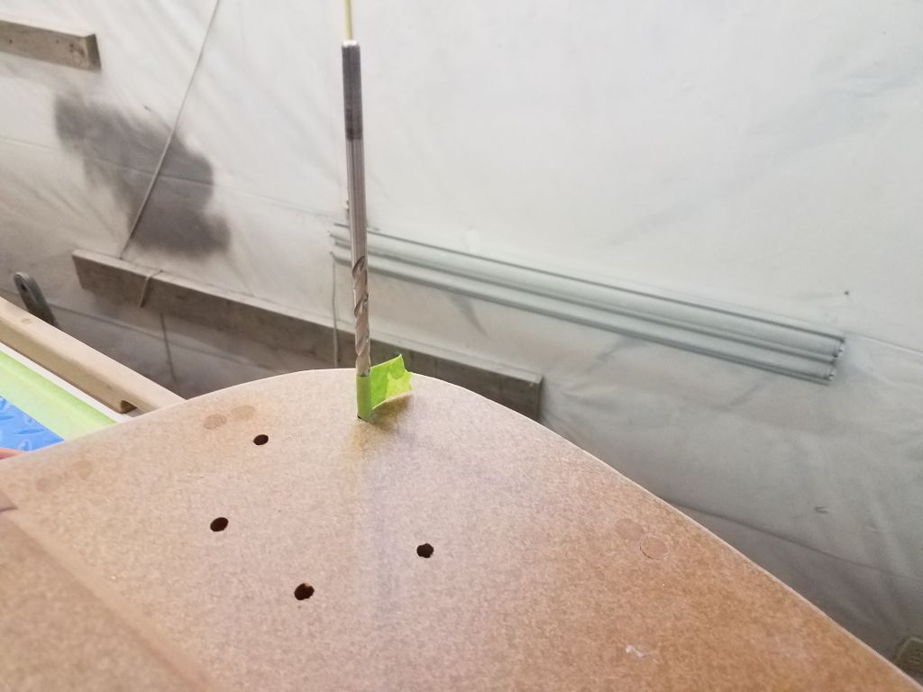
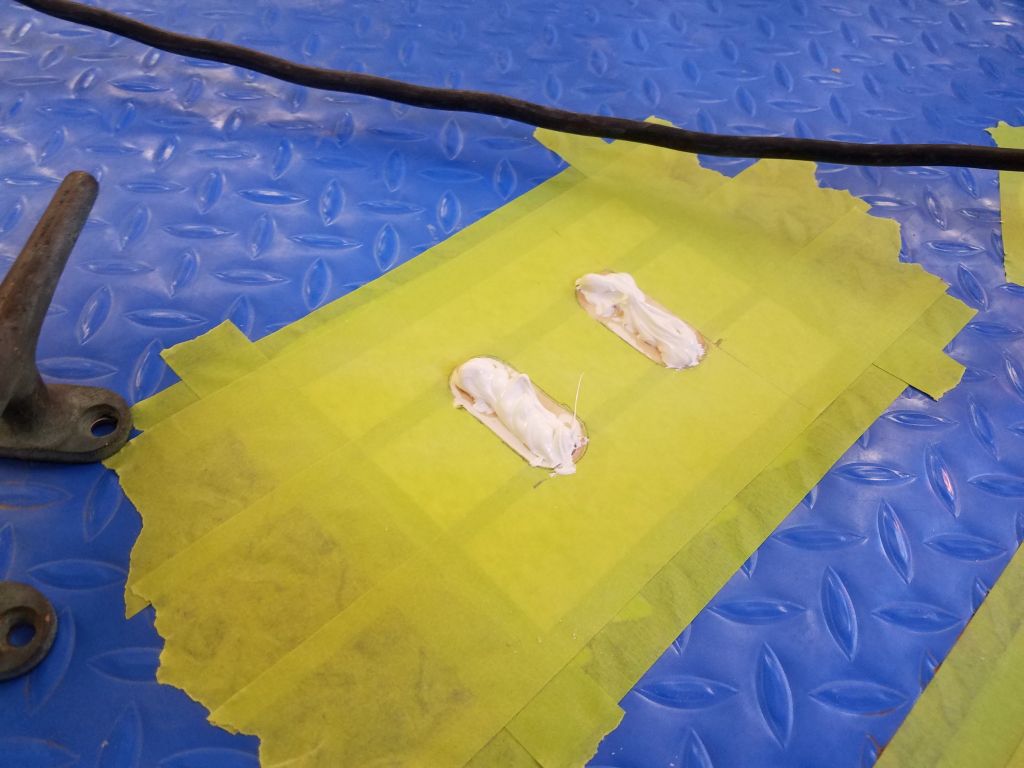
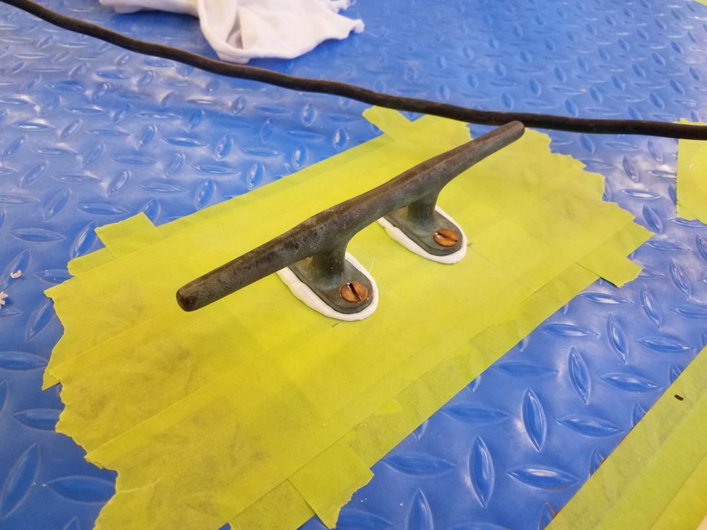
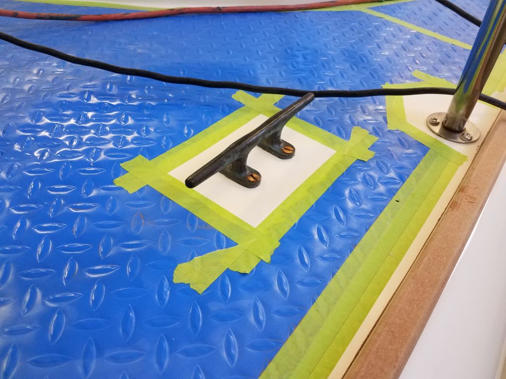
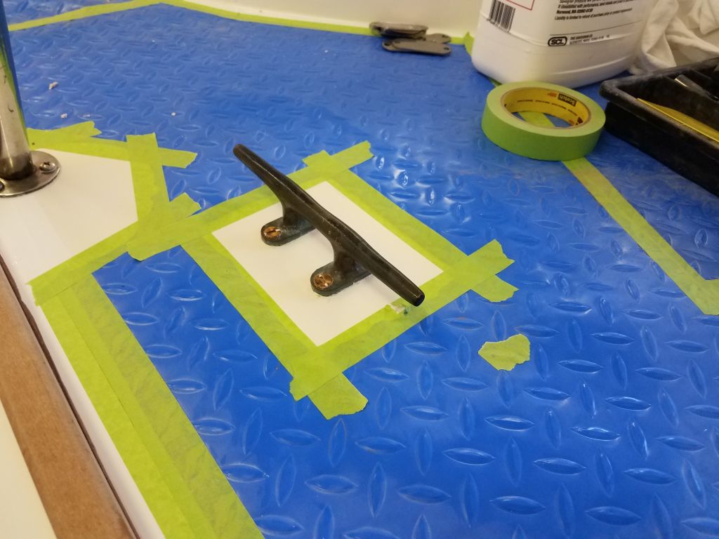
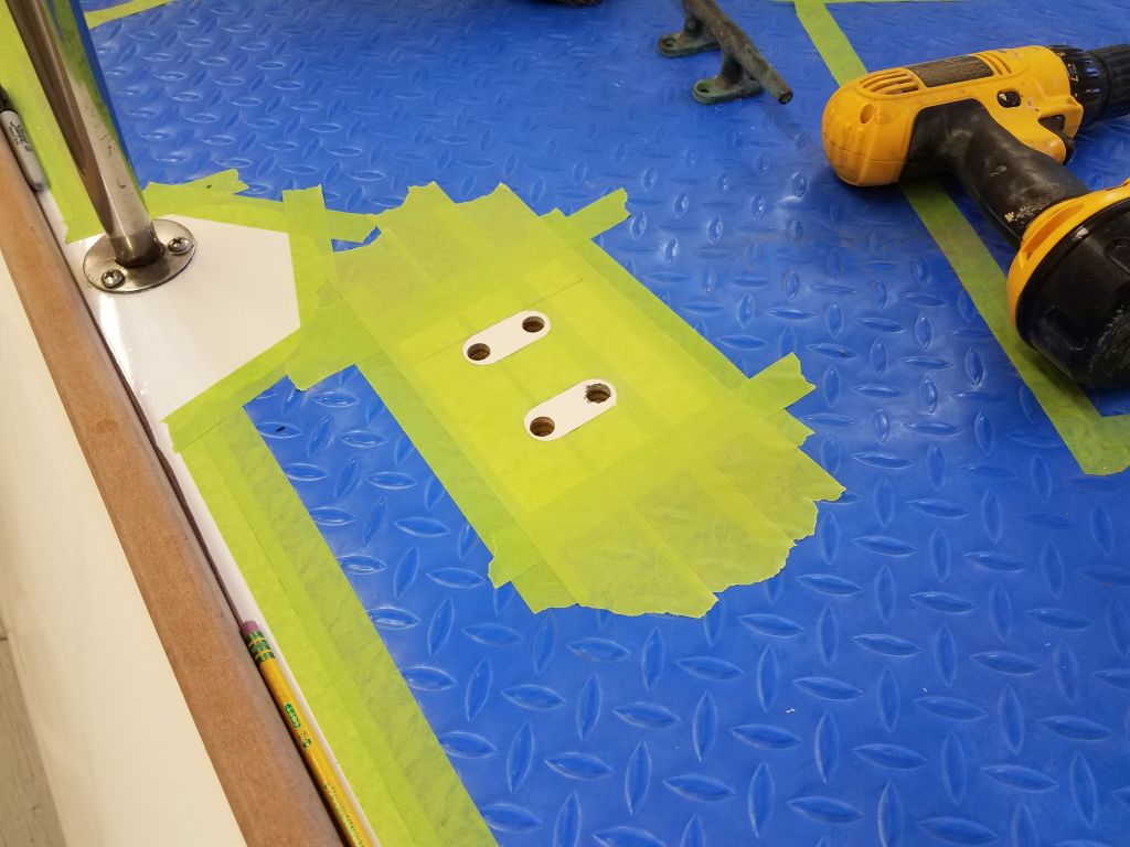
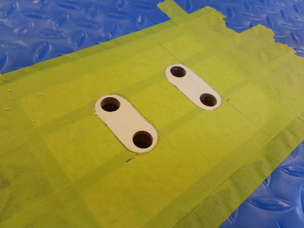
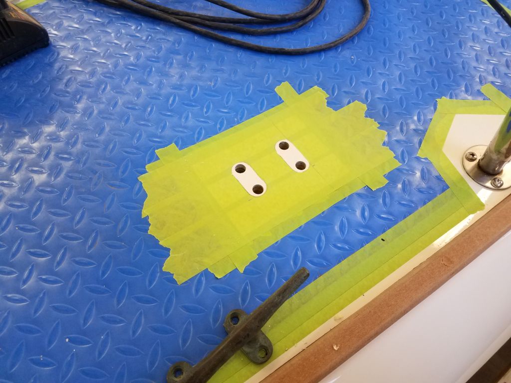
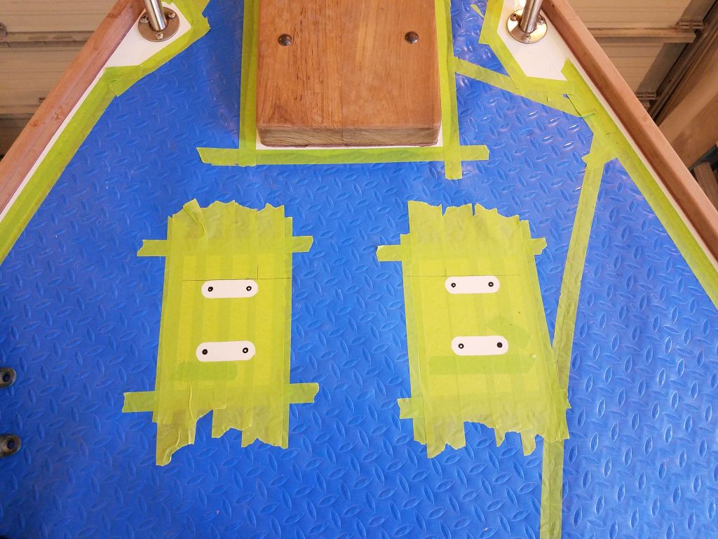
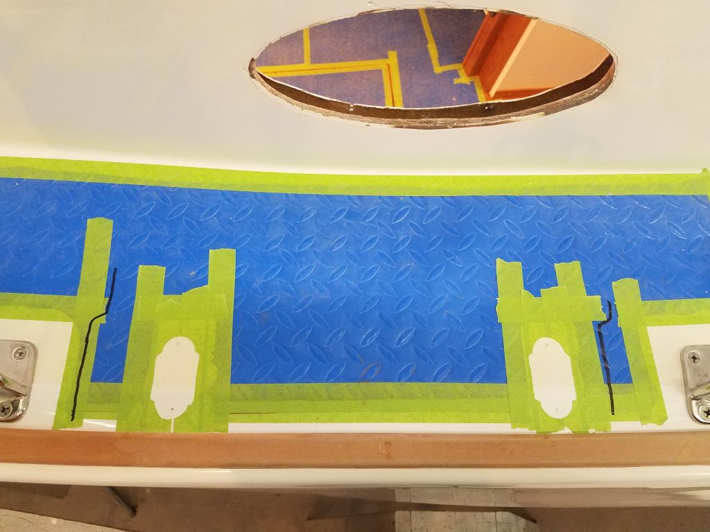
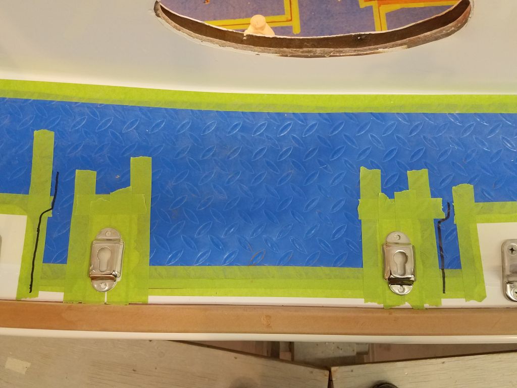
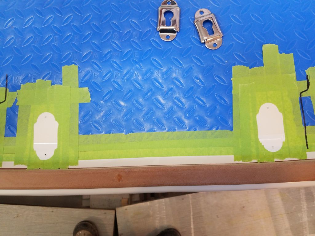
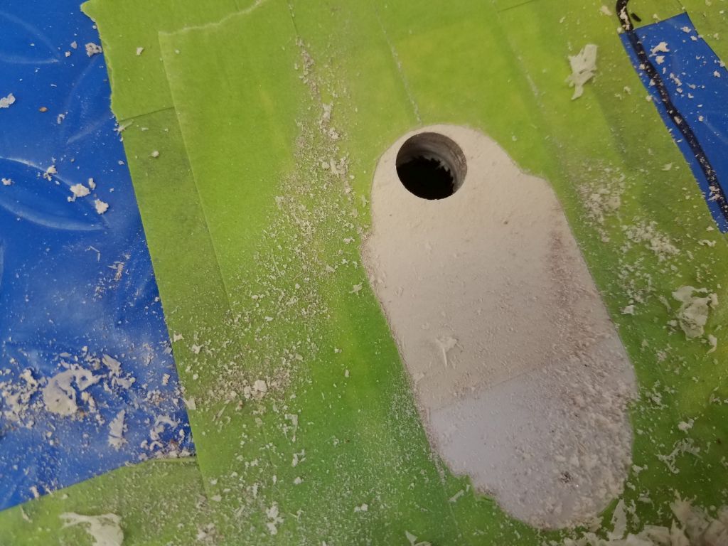
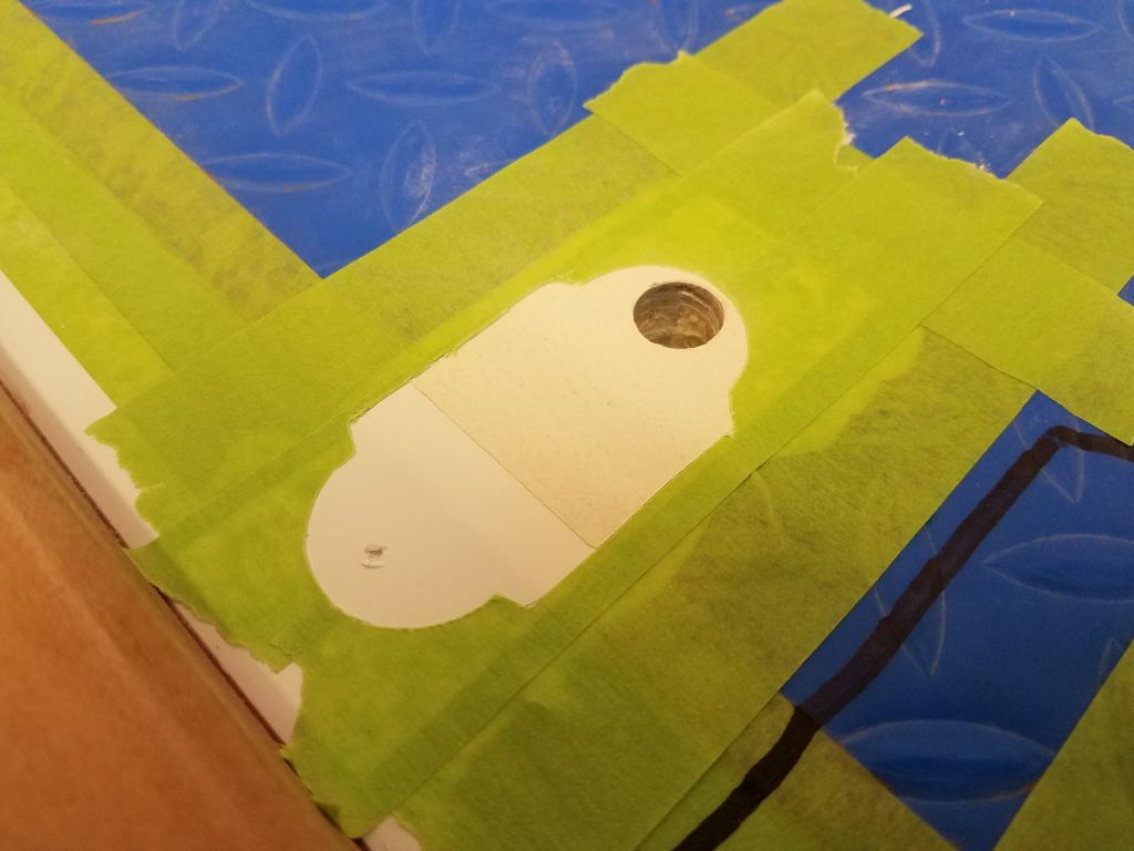
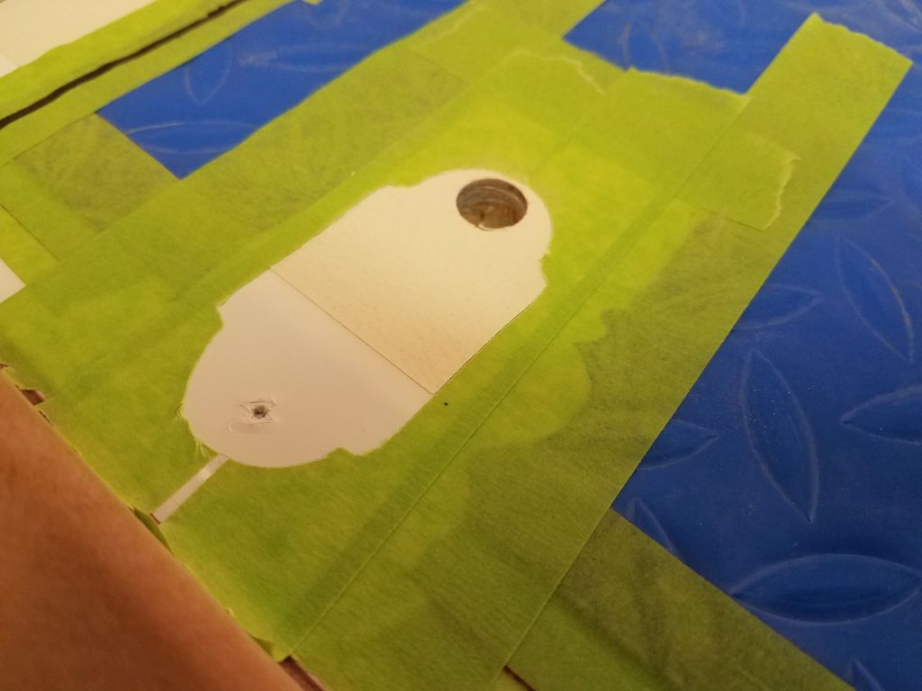
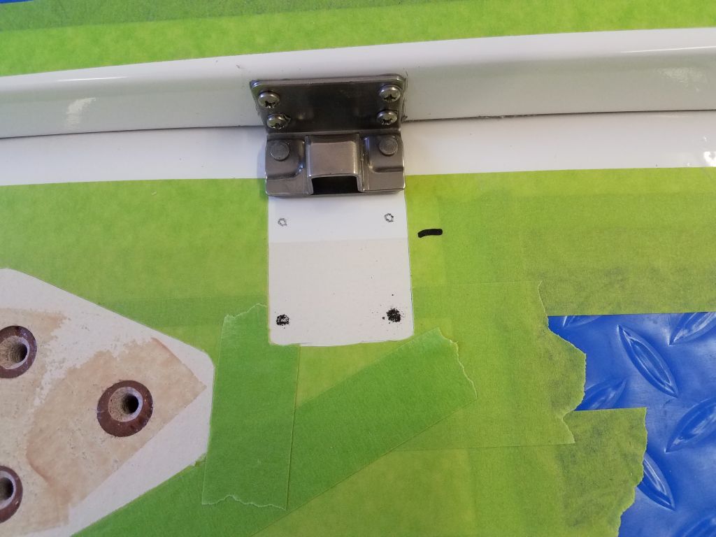
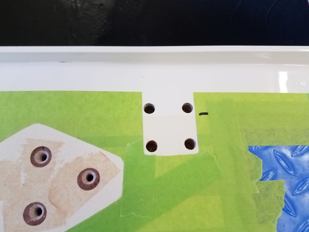
Once that was in place, I could lay out the deck side of the hasp and prepare the holes in the usual way.

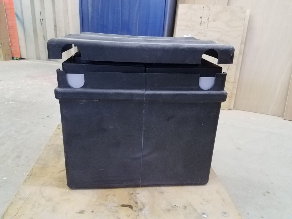
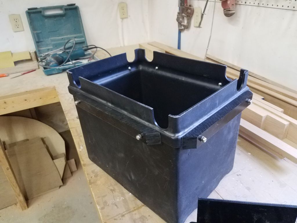
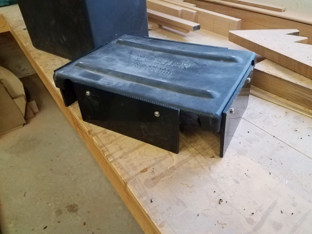
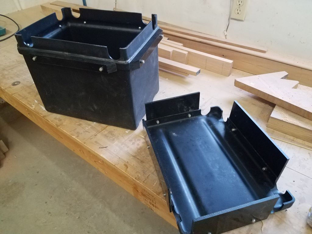
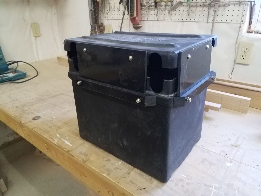
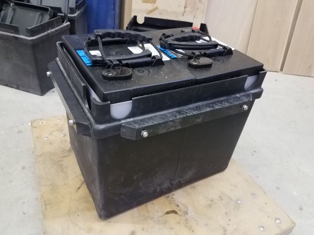
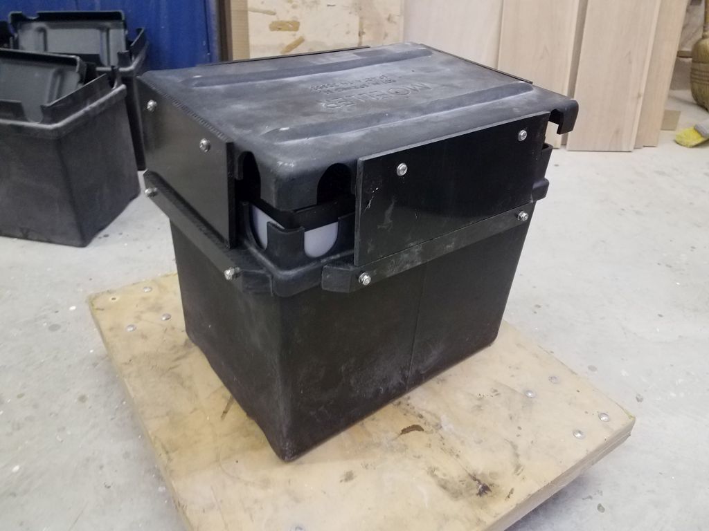
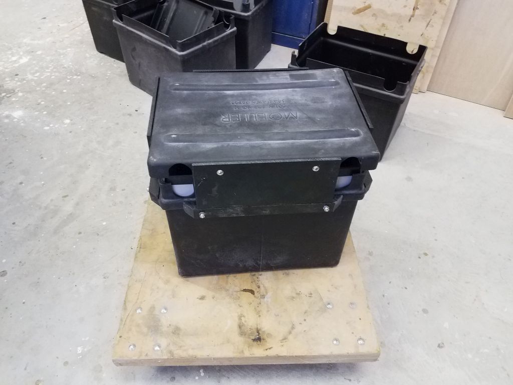
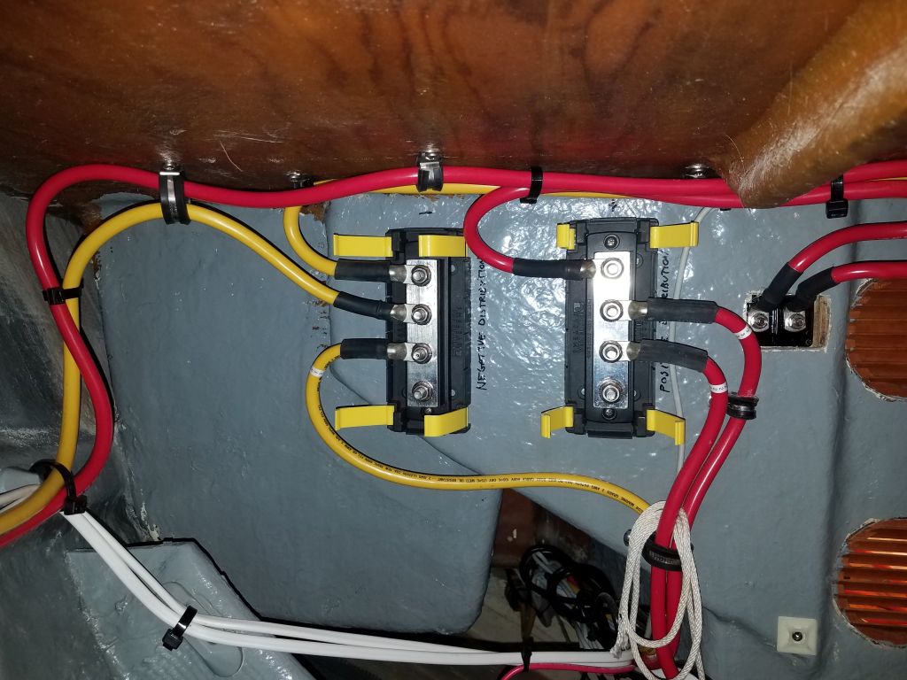
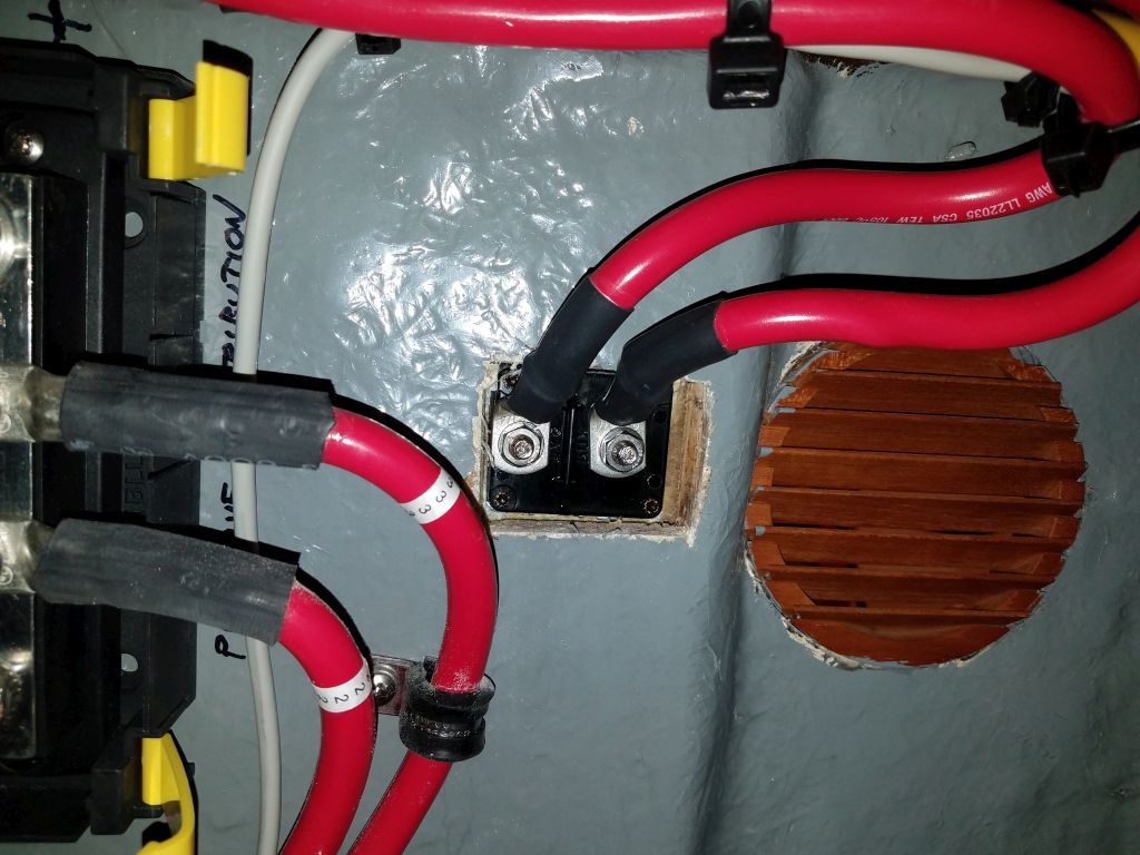
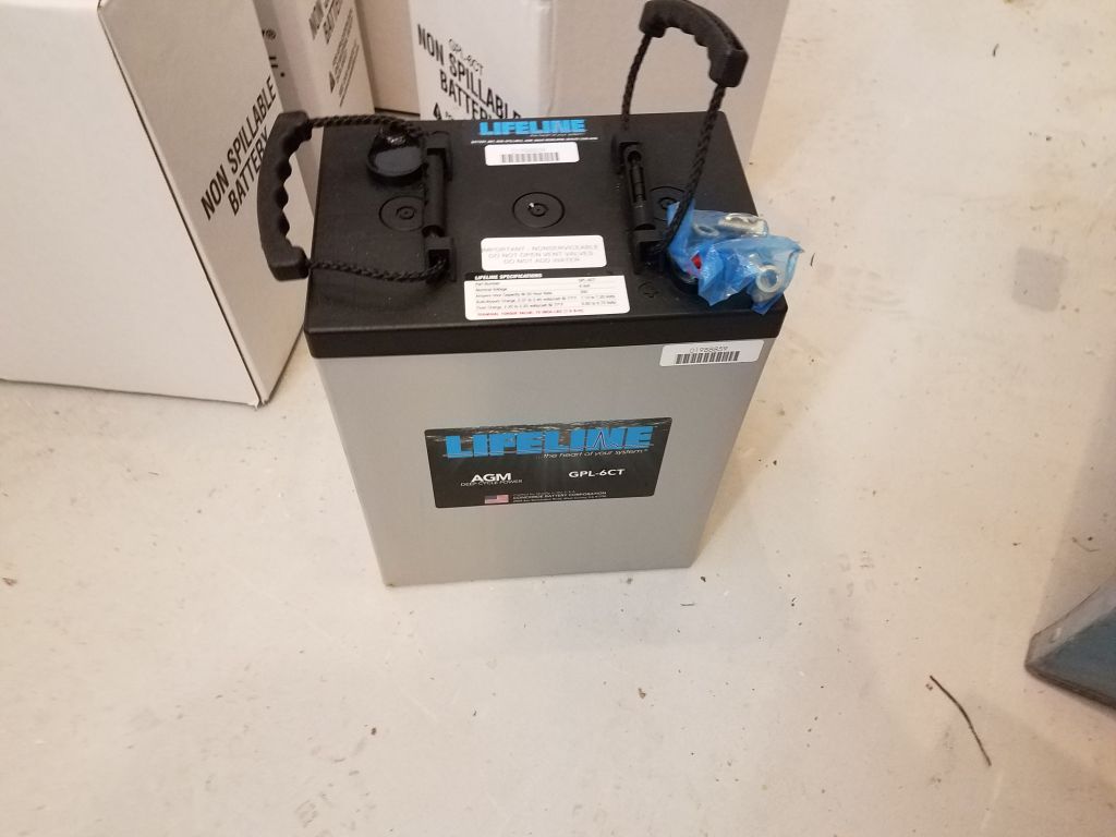
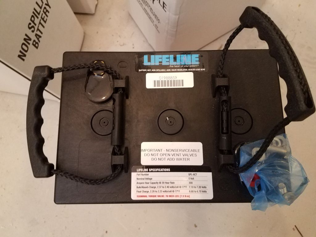
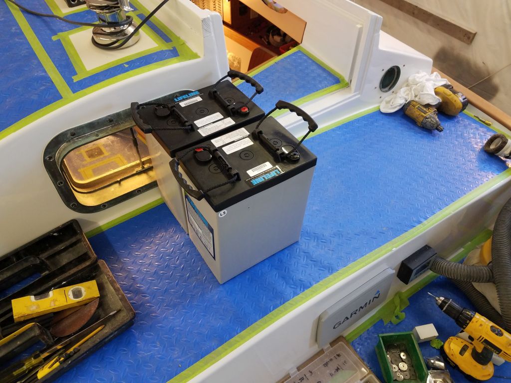
During a couple of my normal trips up and down the ladder in the morning, I lifted two of the new batteries up on deck, and eventually into the cabin, working in stages:  each battery weighed around 90 pounds, so to lift the batteries 10′ up to the deck, then down 6′ into the cabin, and using the formula W = Fs, where W is the amount of work done in Newtons, F is the amount of force applied (1 Lackey), and s is…well, it’s been a long time since school, but it was a lot of work.  Too much, really, and I vowed to find other than human means to raise the remaining 8 batteries, but for now the two house batteries were aboard, and I looked forward to finishing up their installation so I could test the electrical installations.

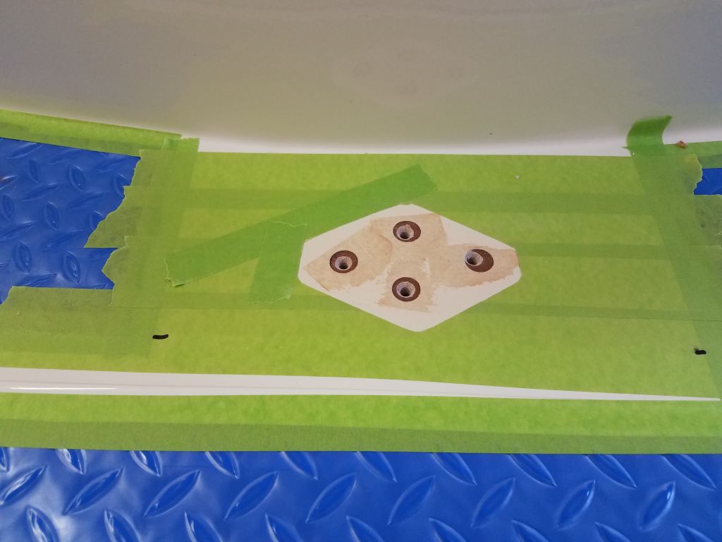
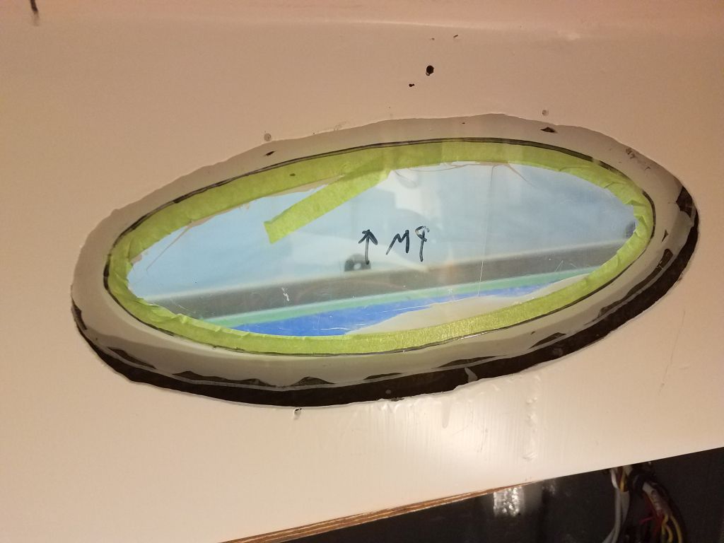
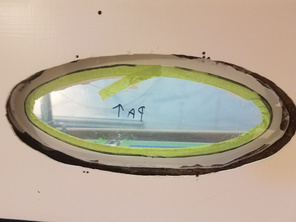
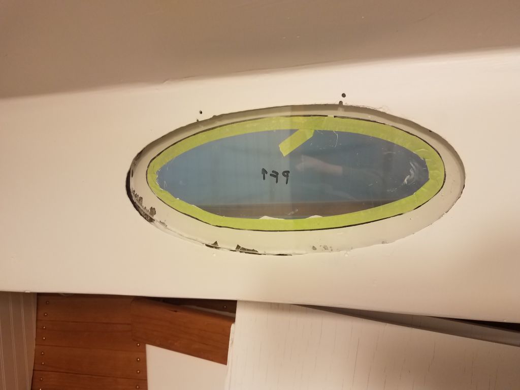
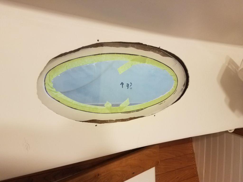
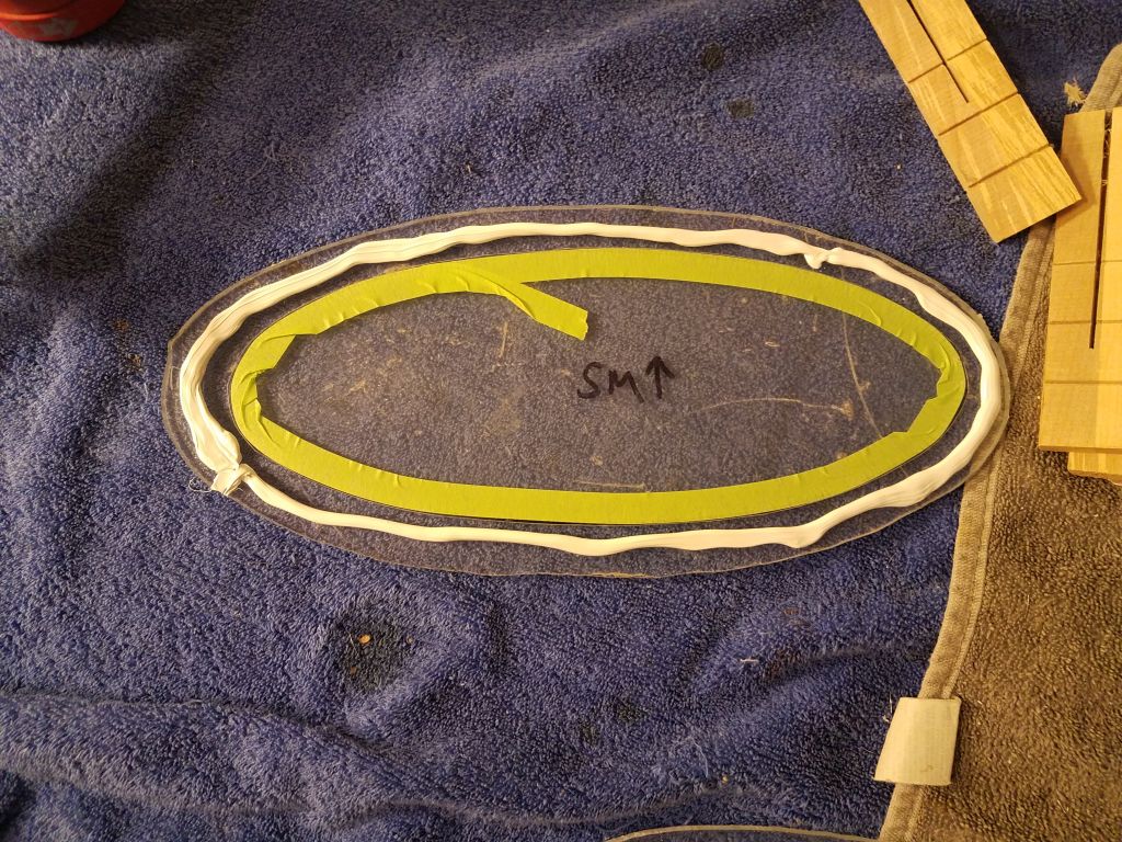
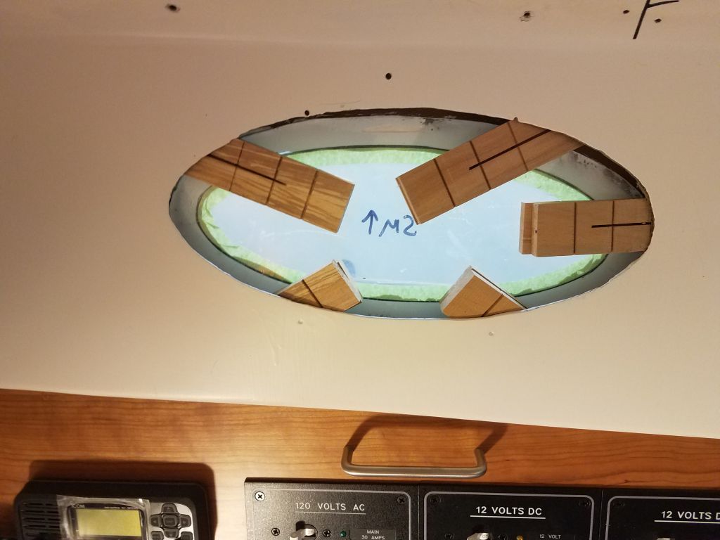
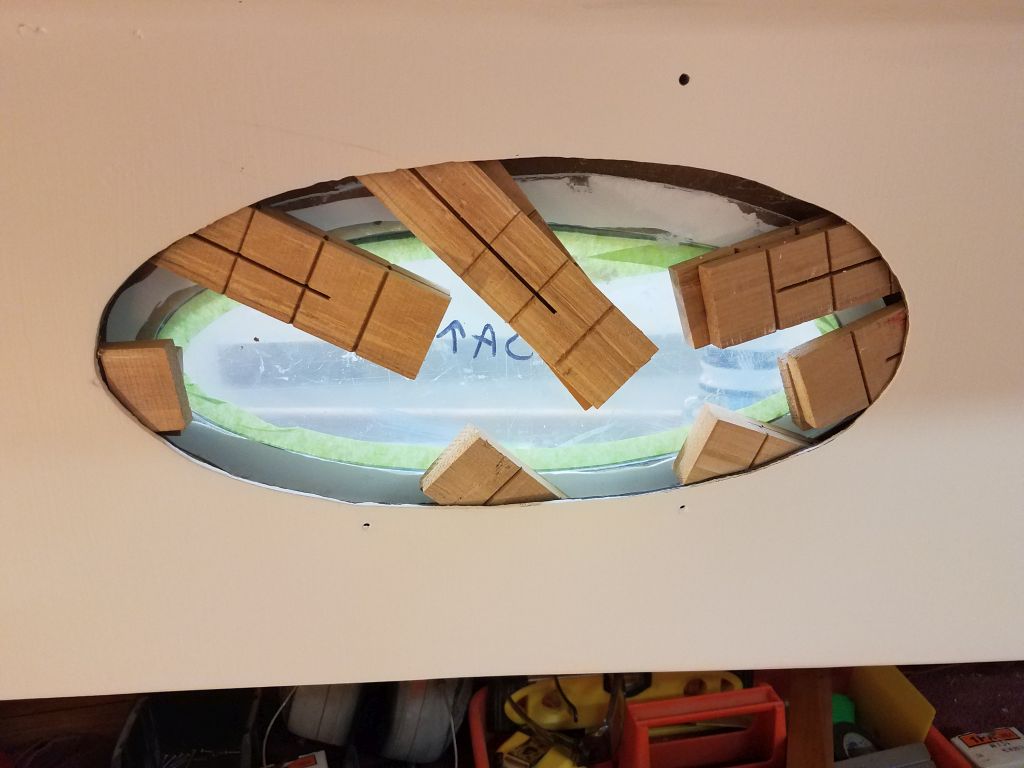
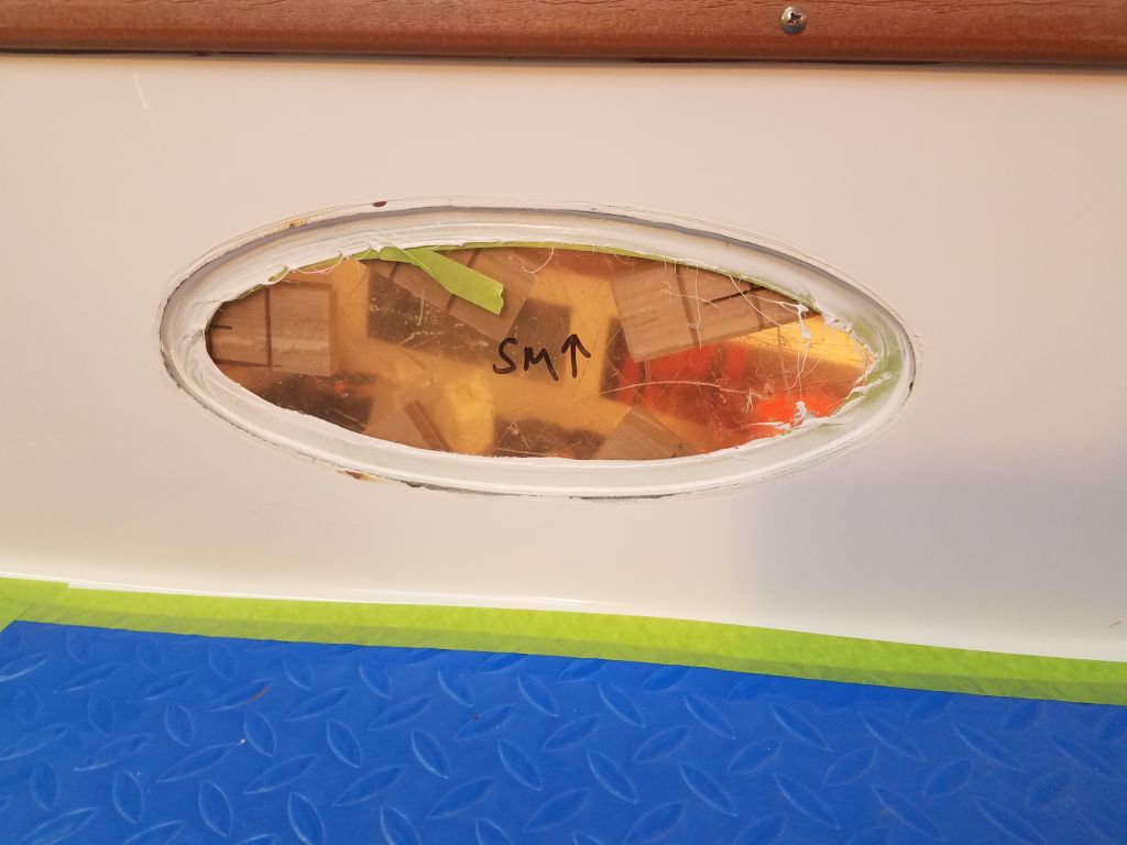
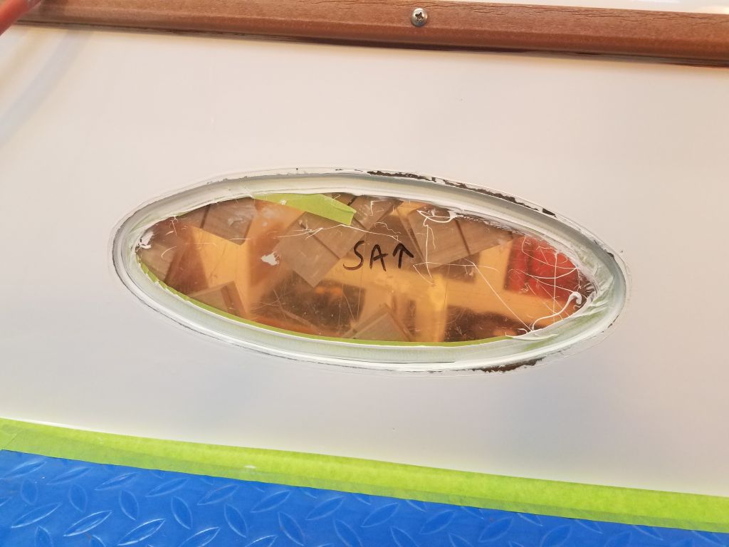
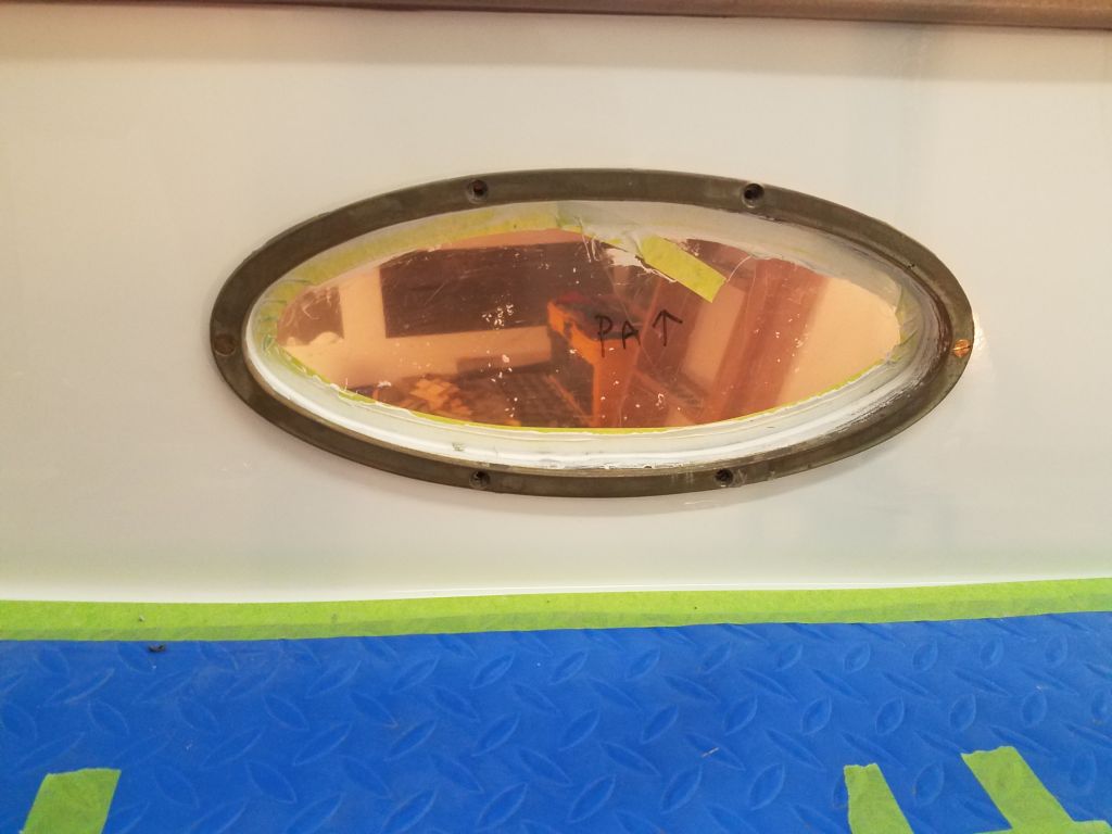
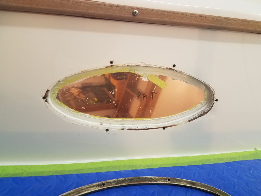
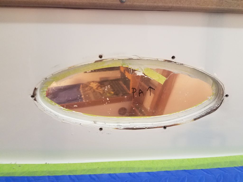
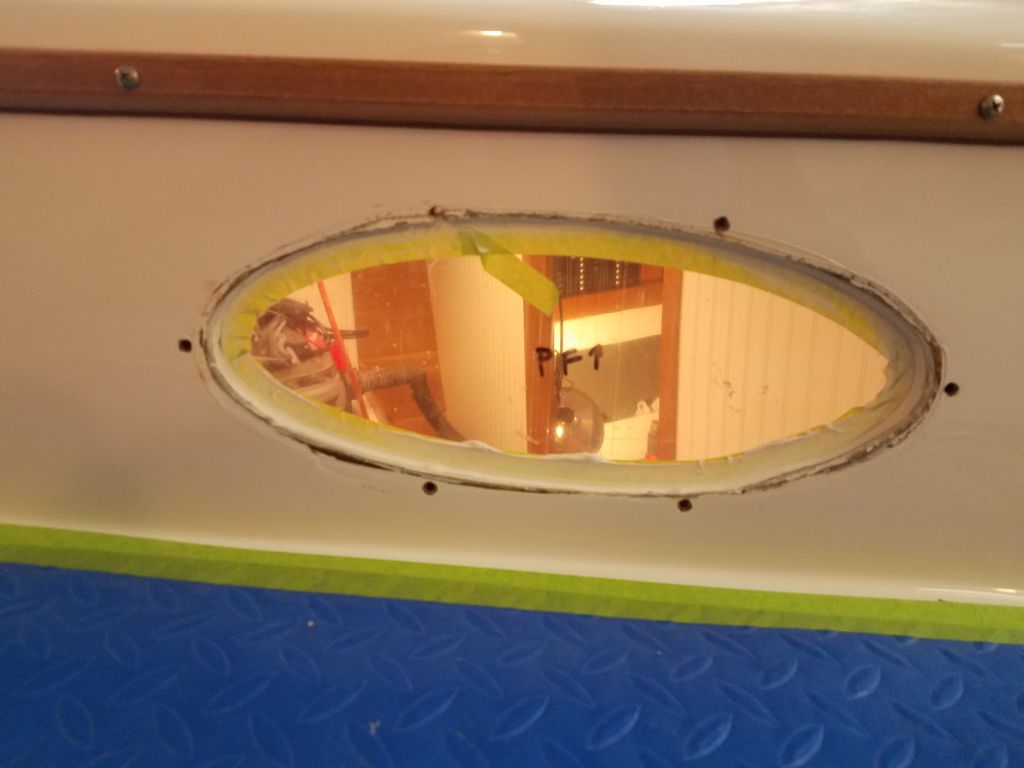
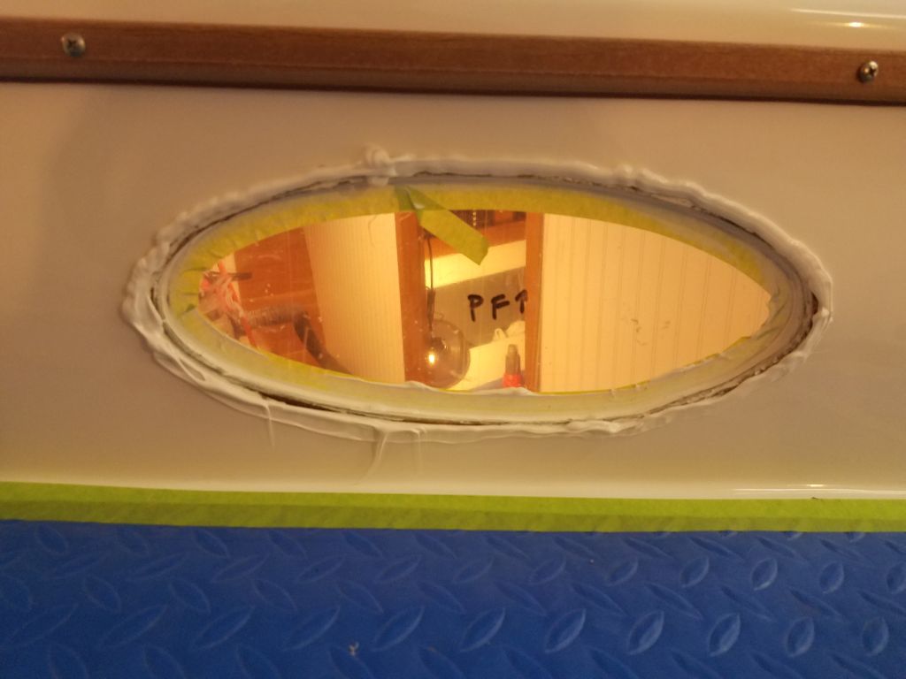
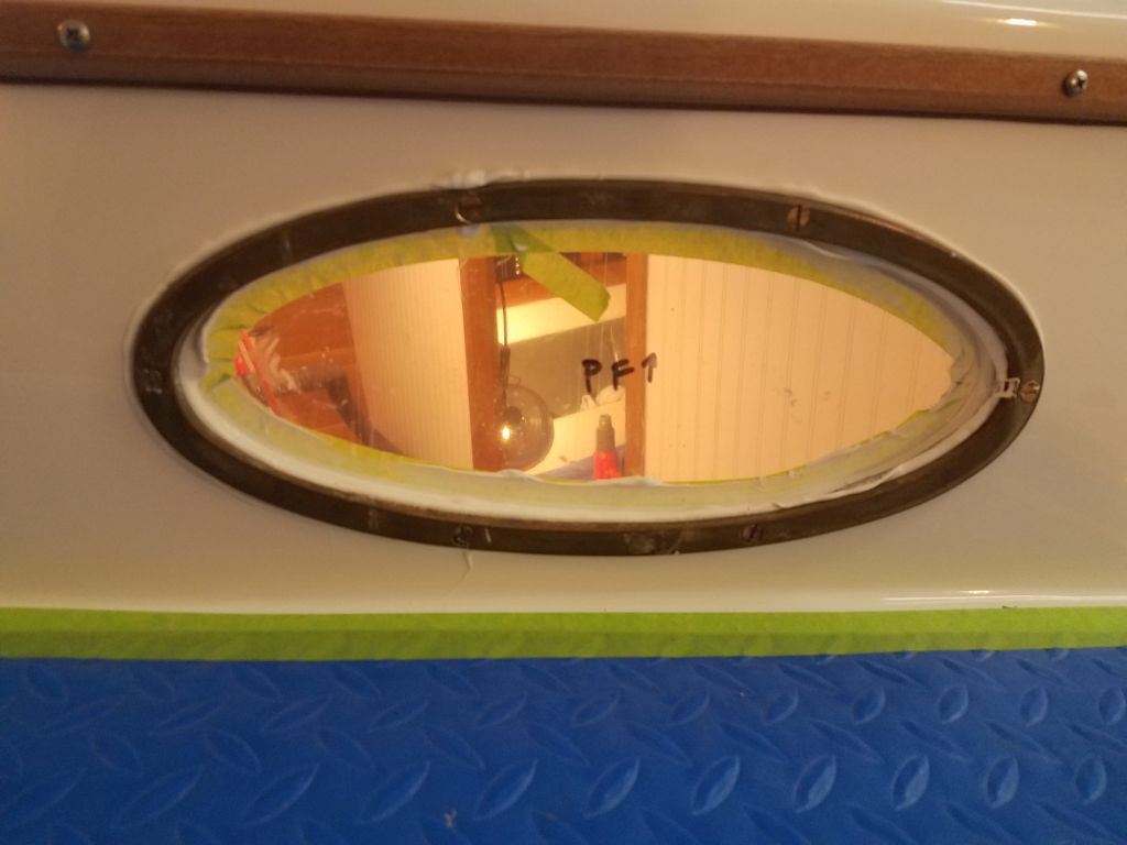
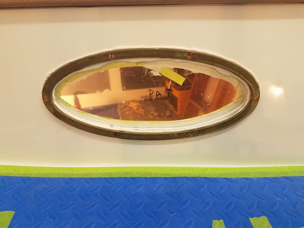
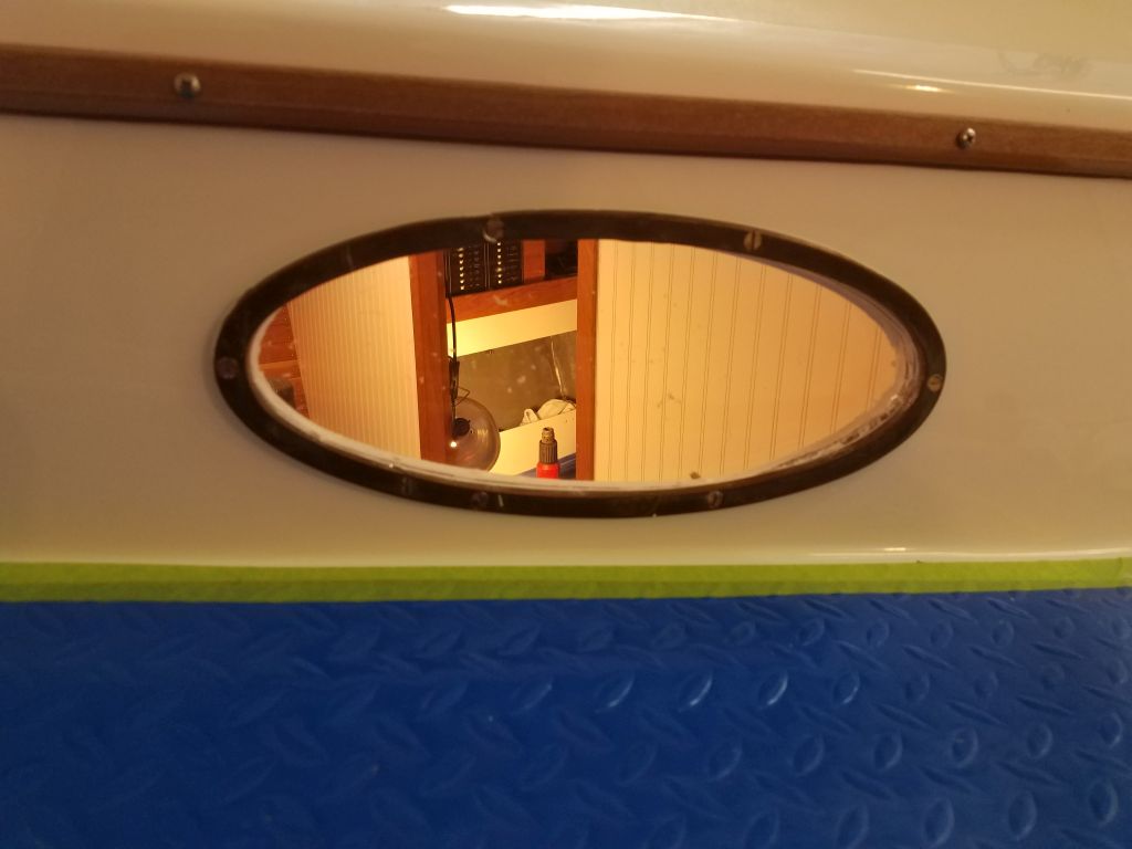
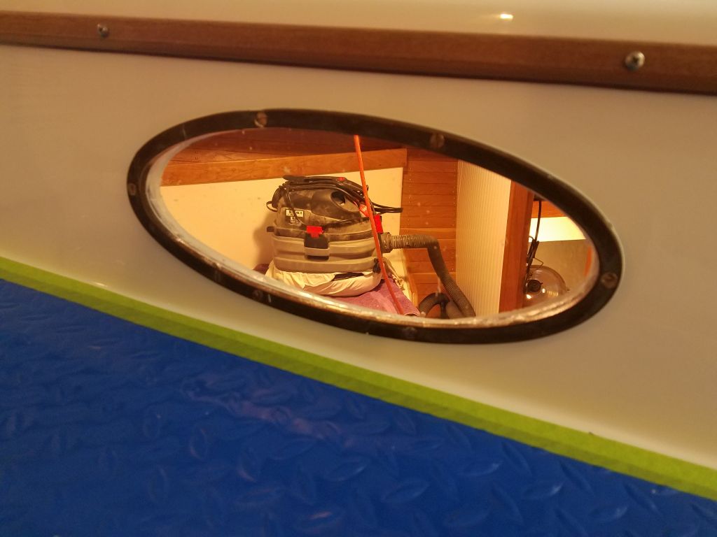
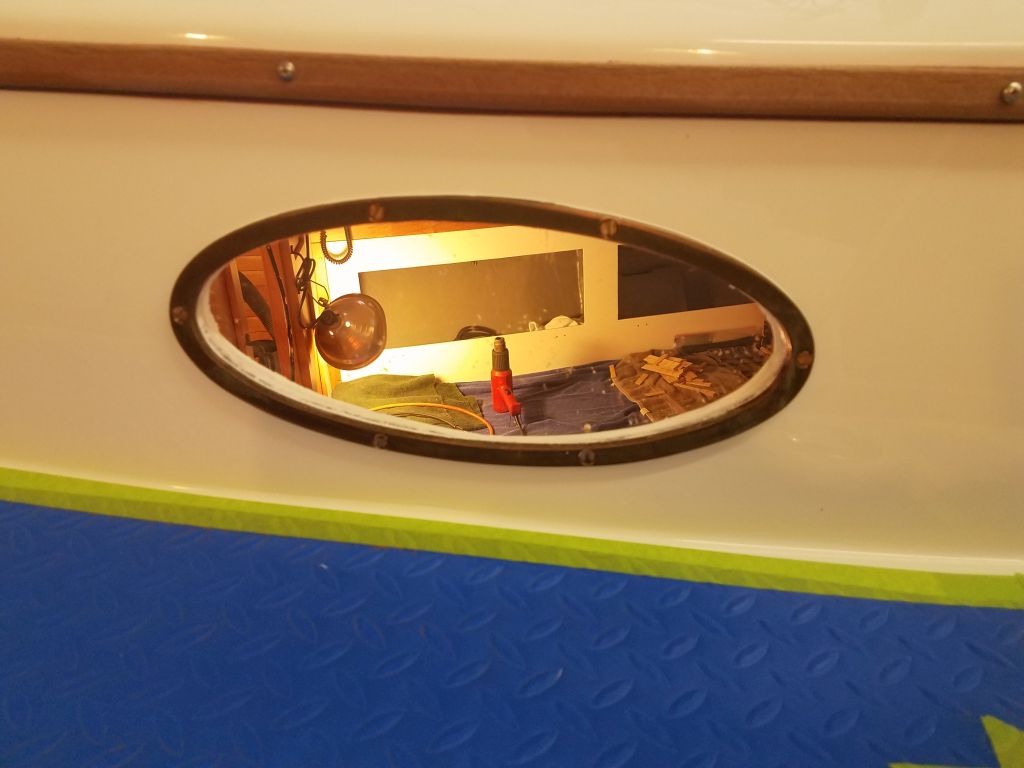
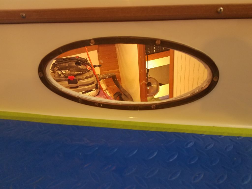
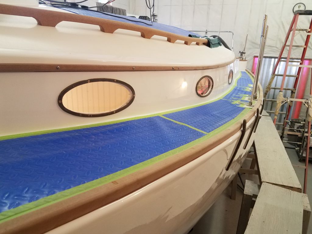
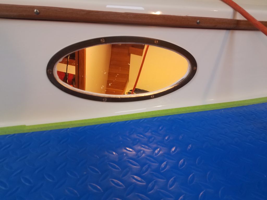
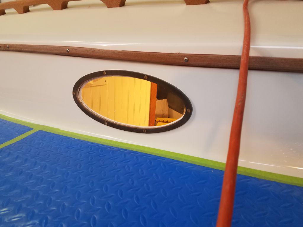
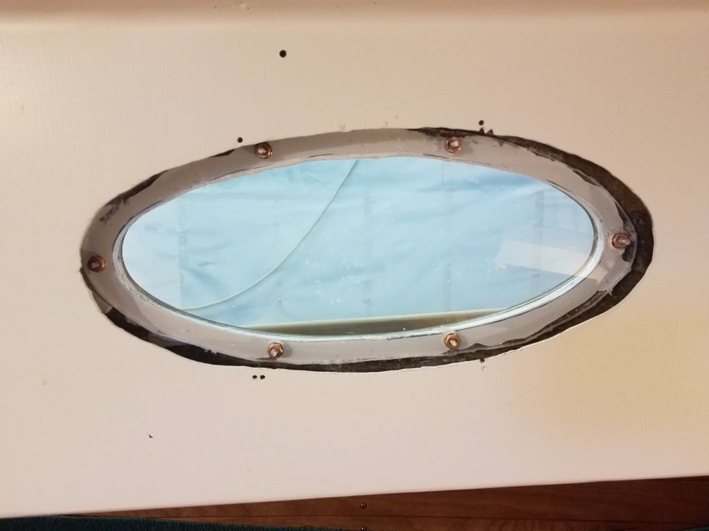
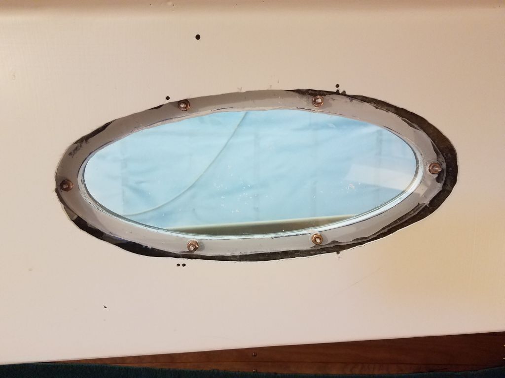
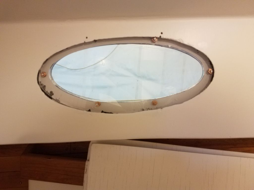
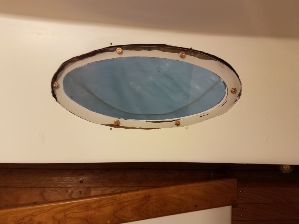
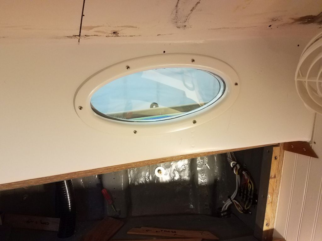
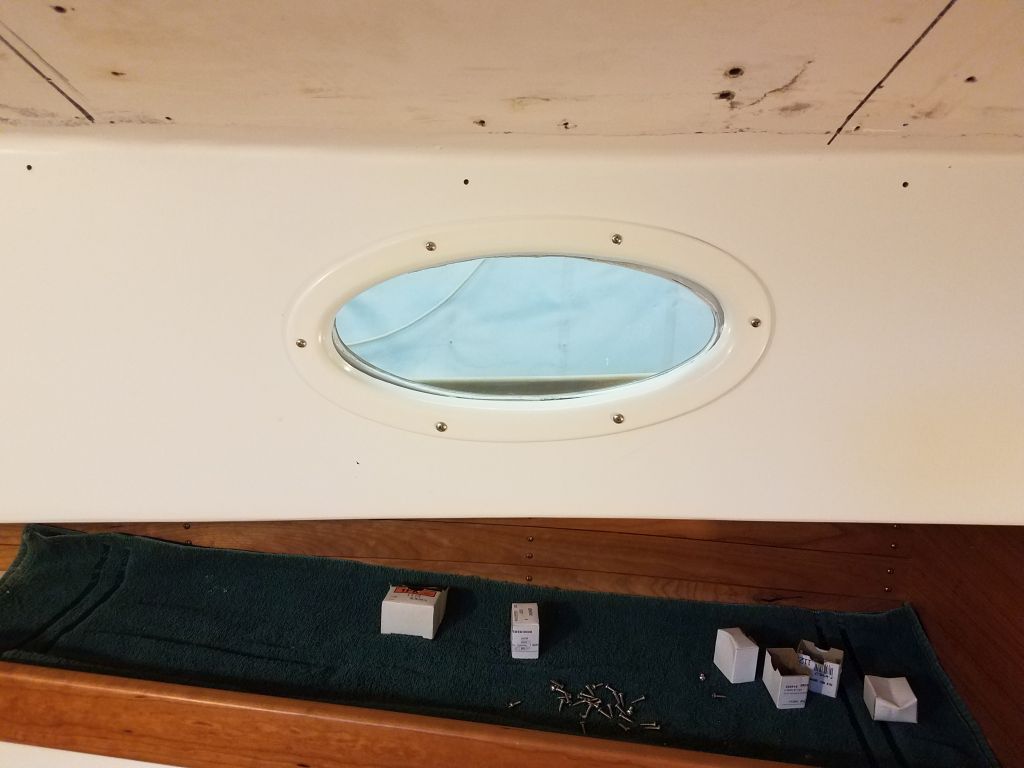
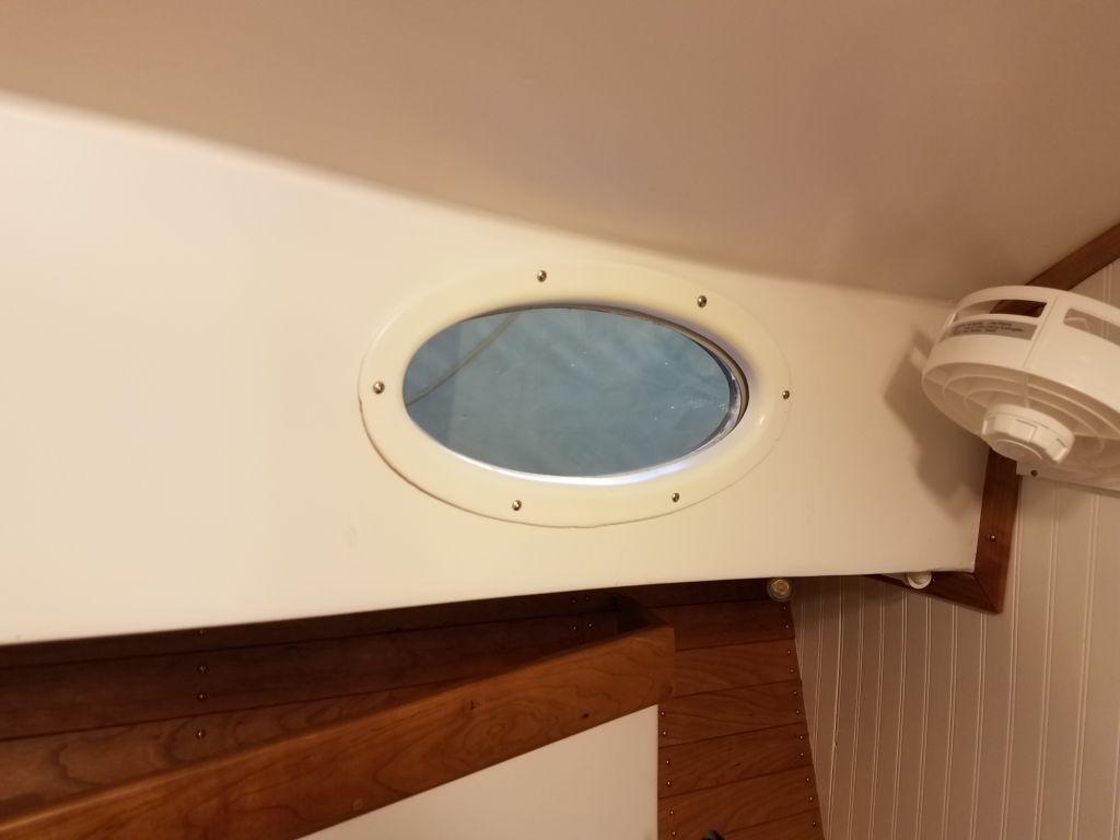
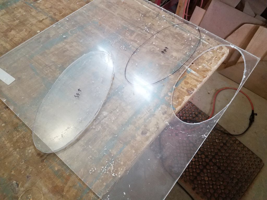
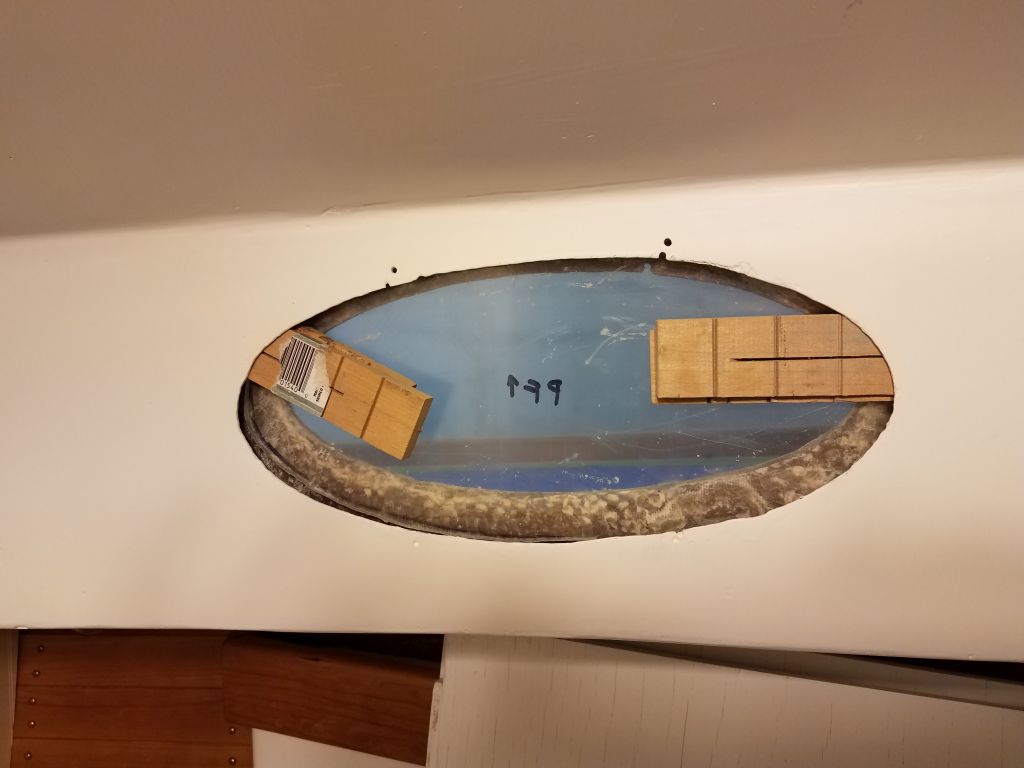
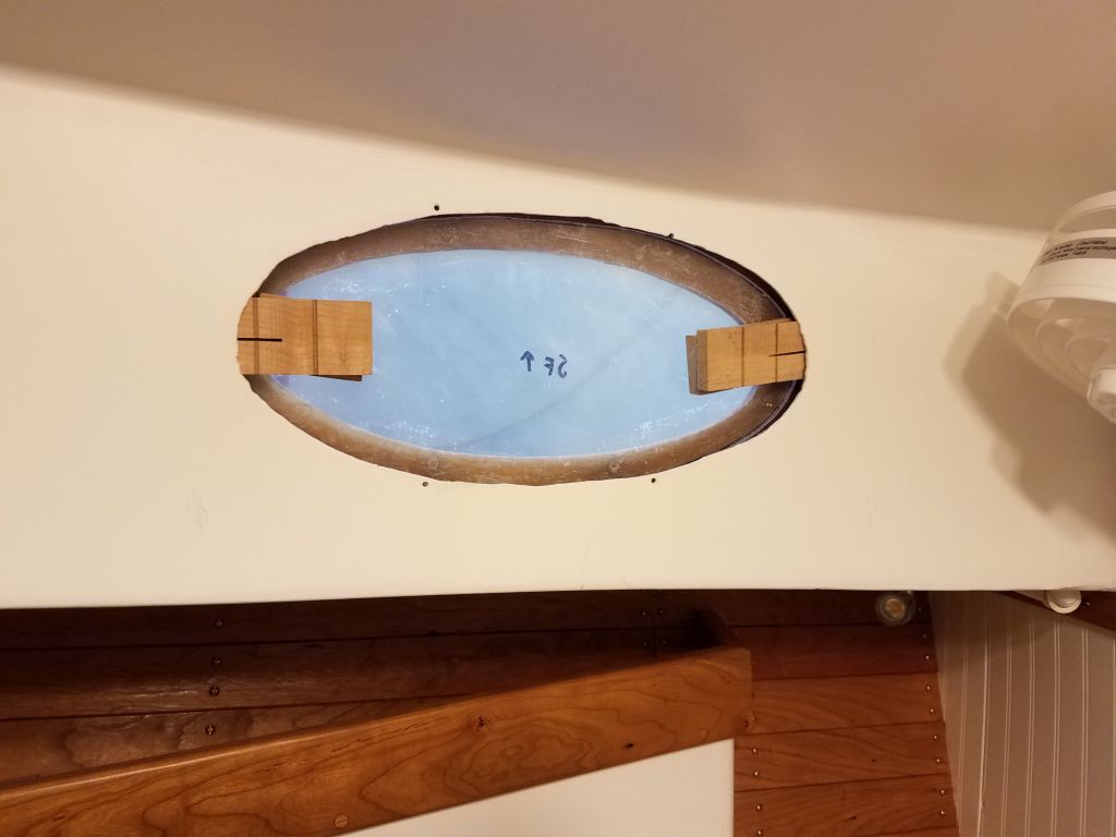
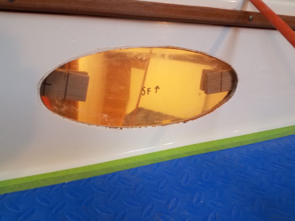
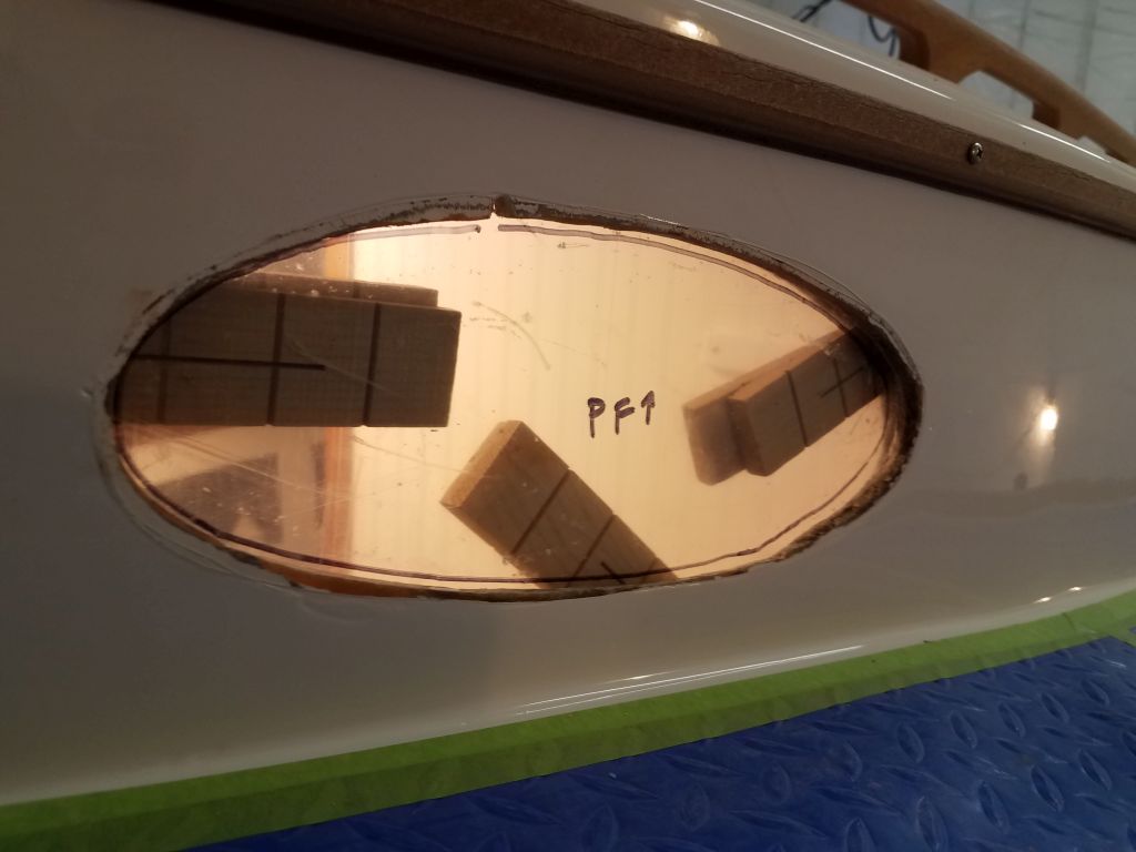
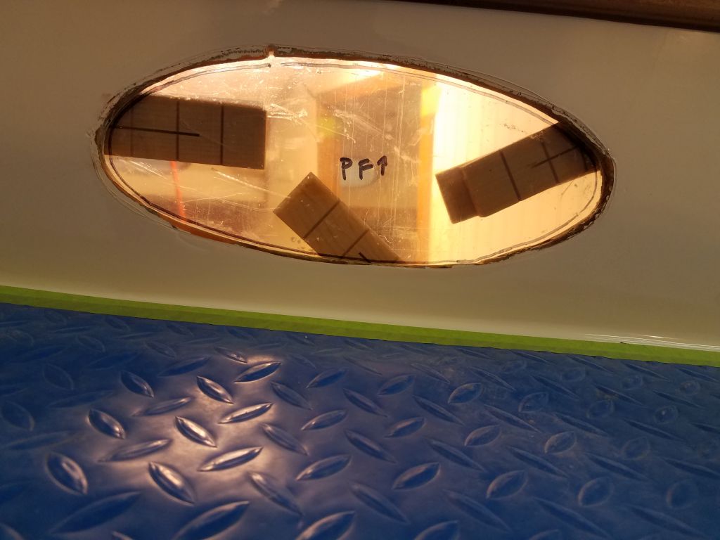
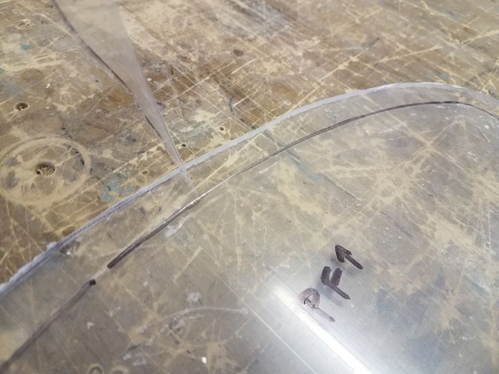
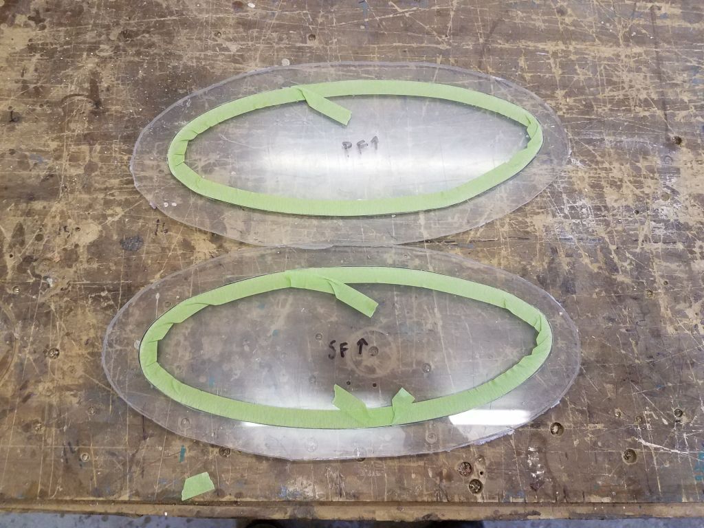
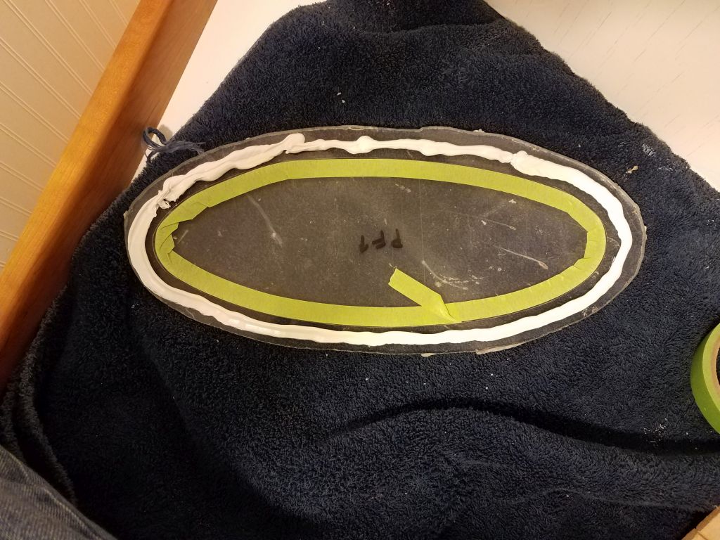
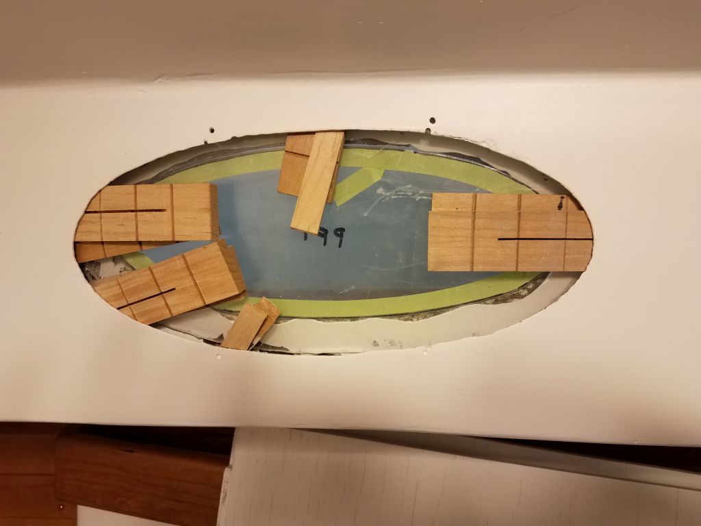
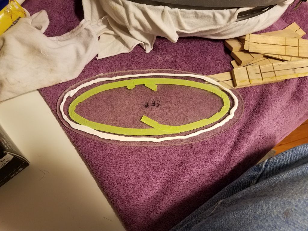
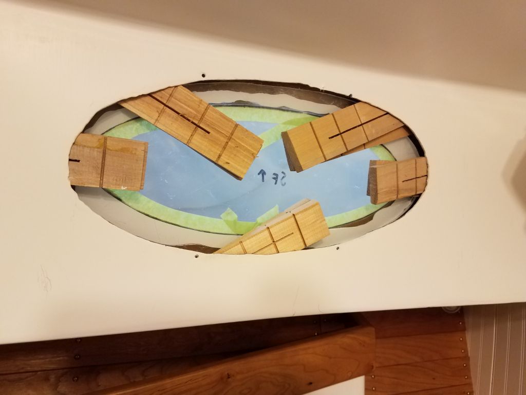
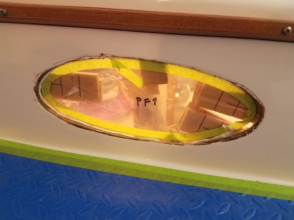
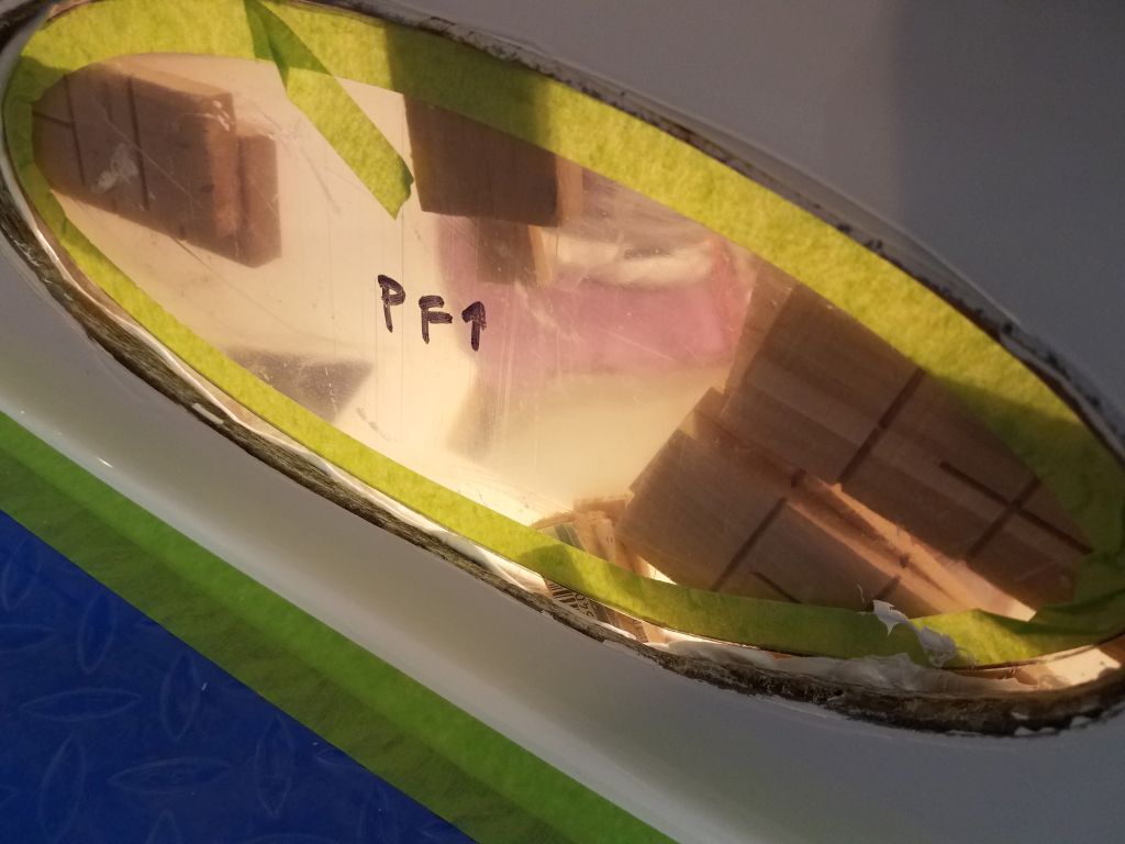
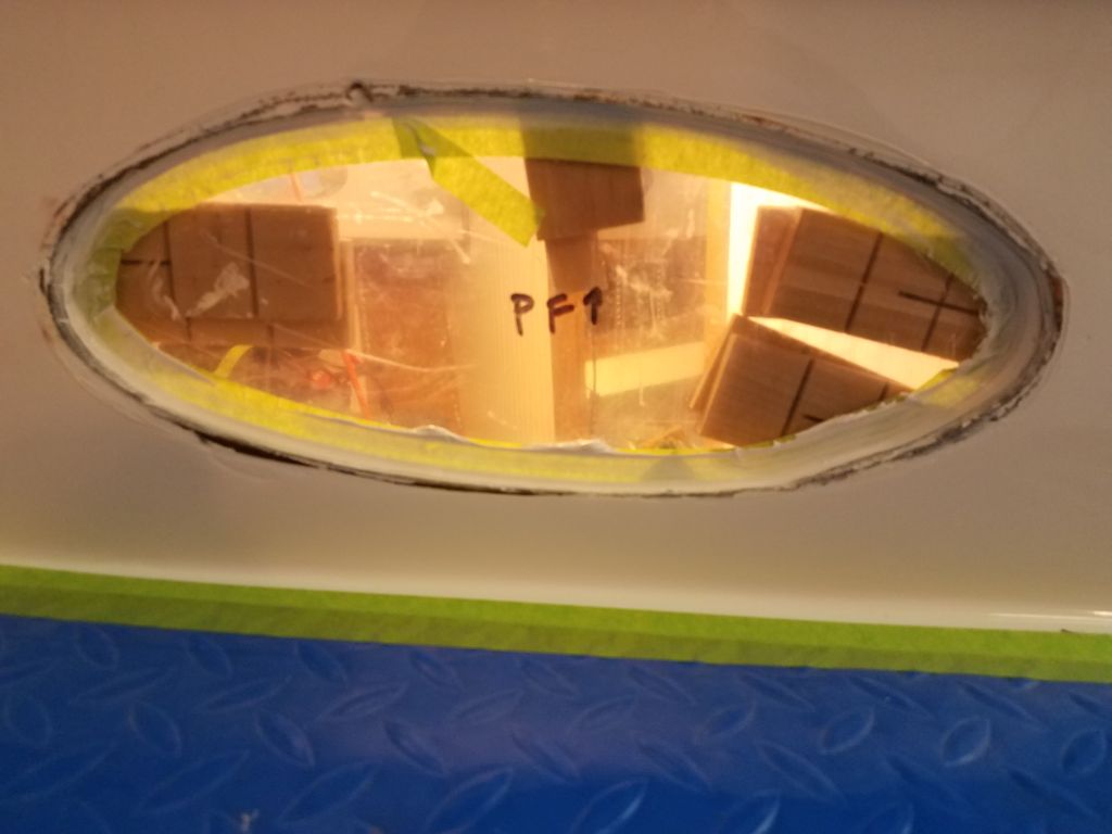
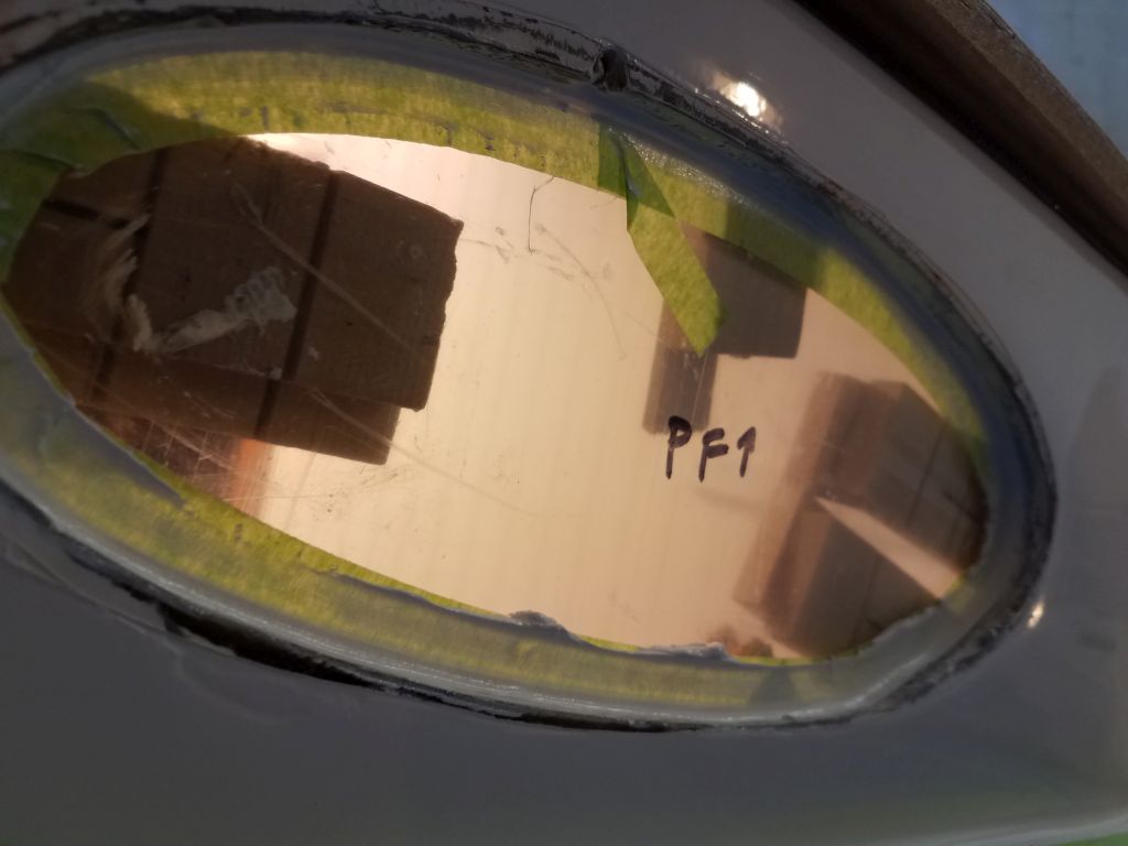
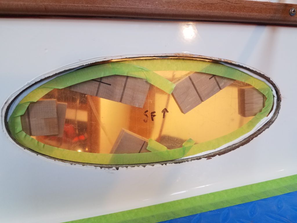
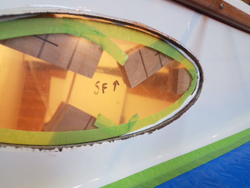
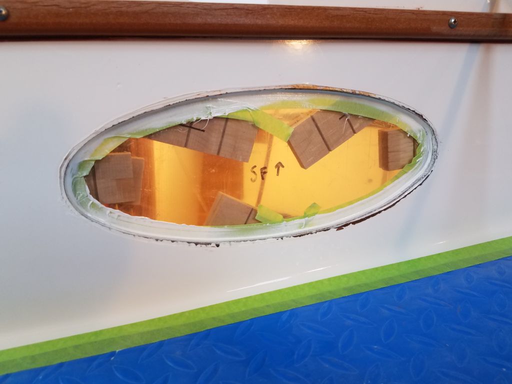
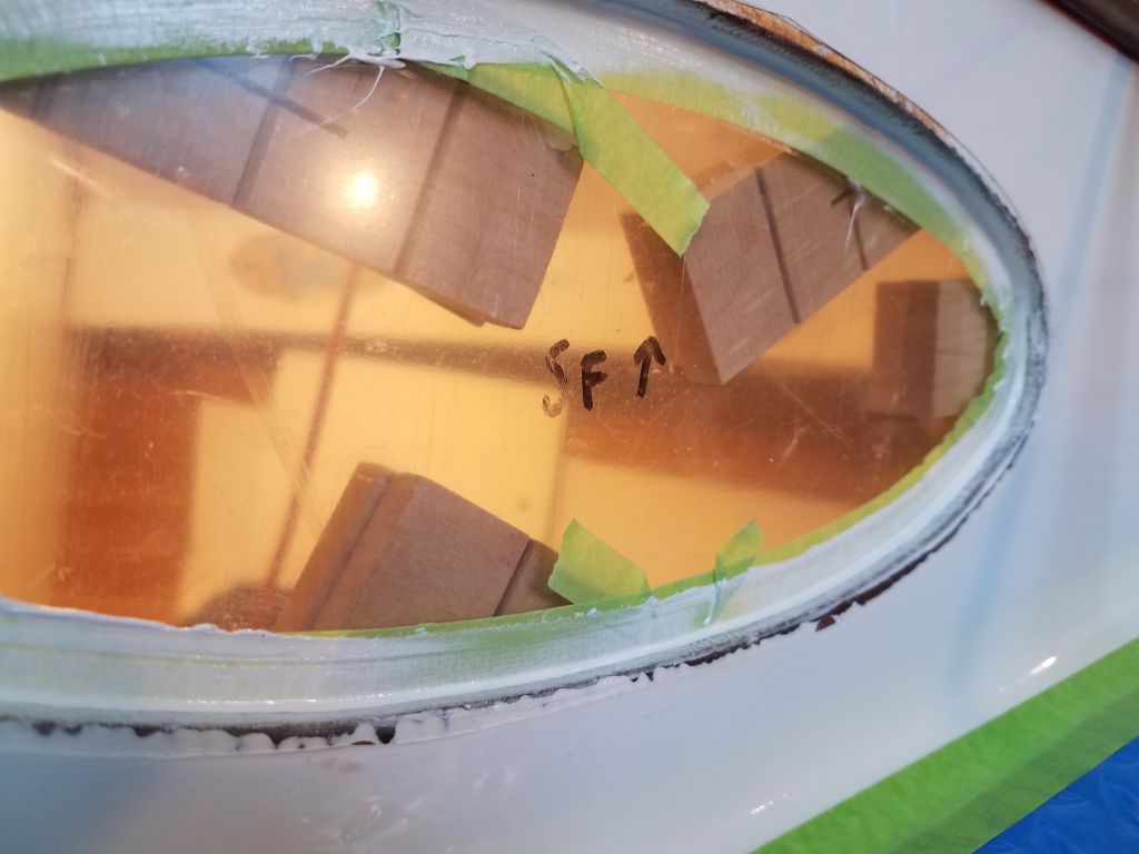
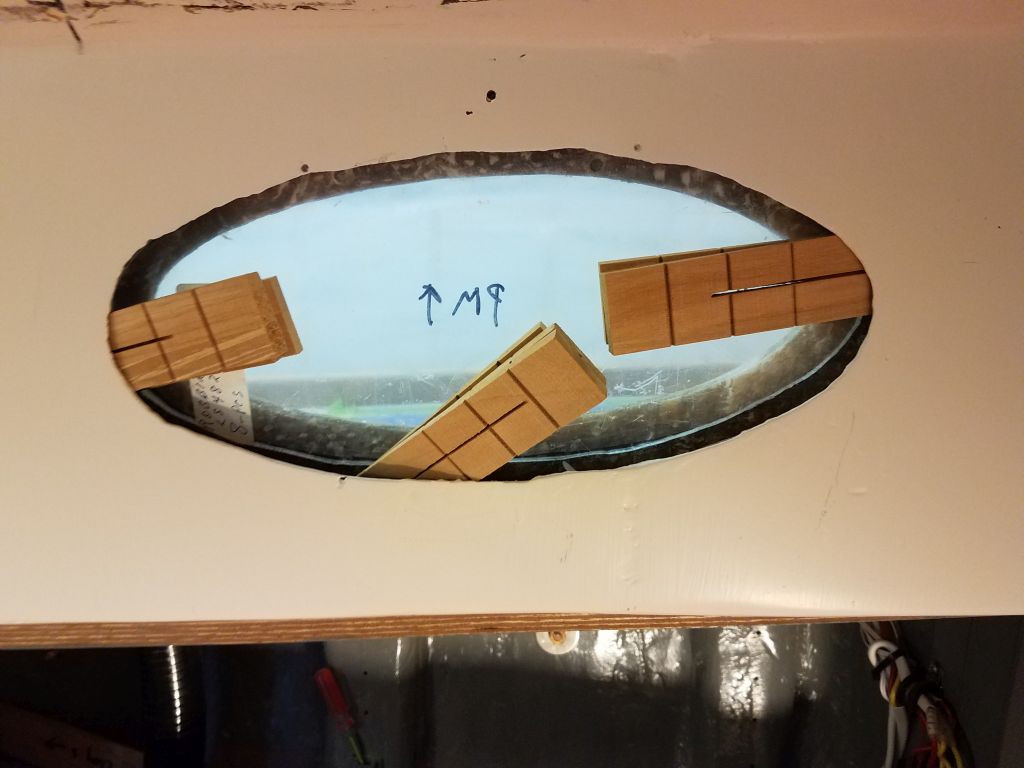
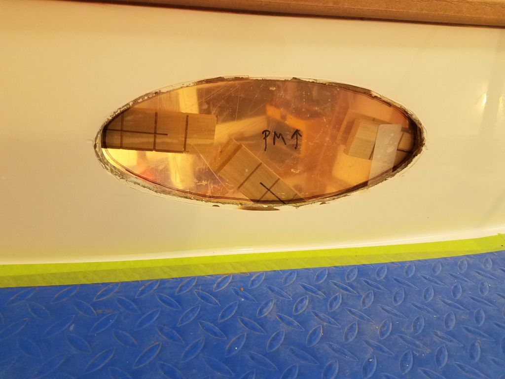
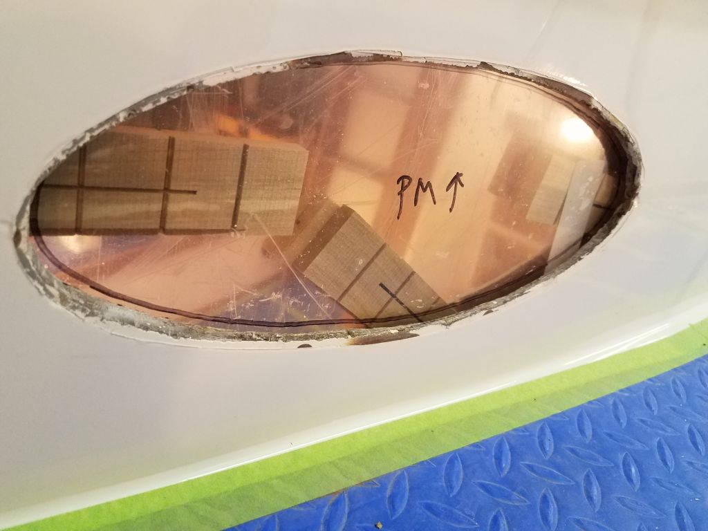
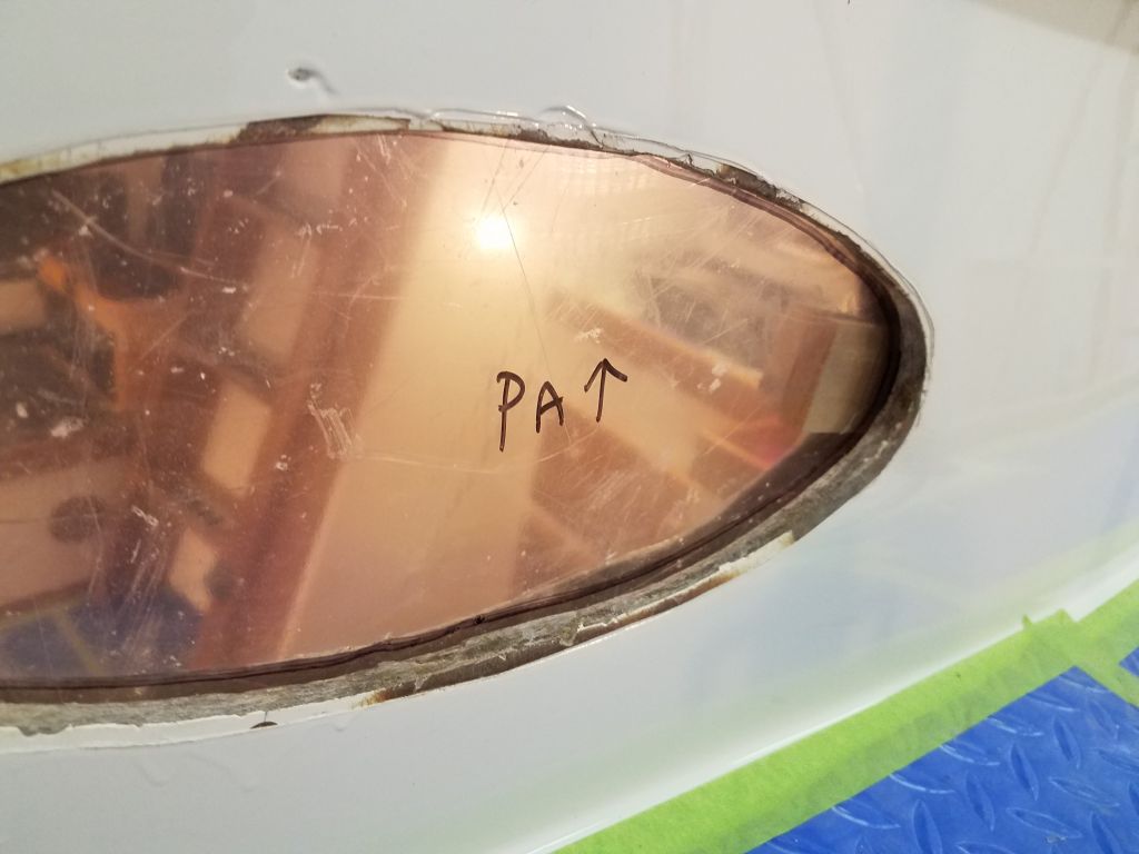
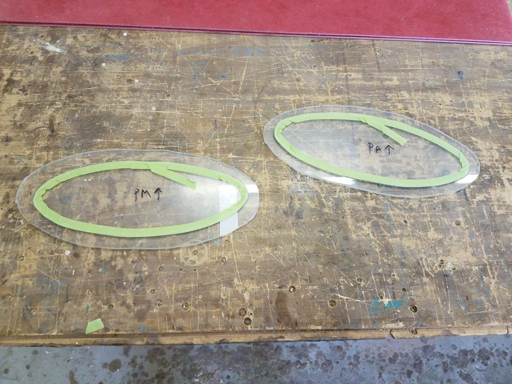
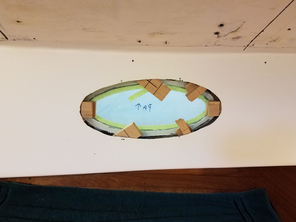
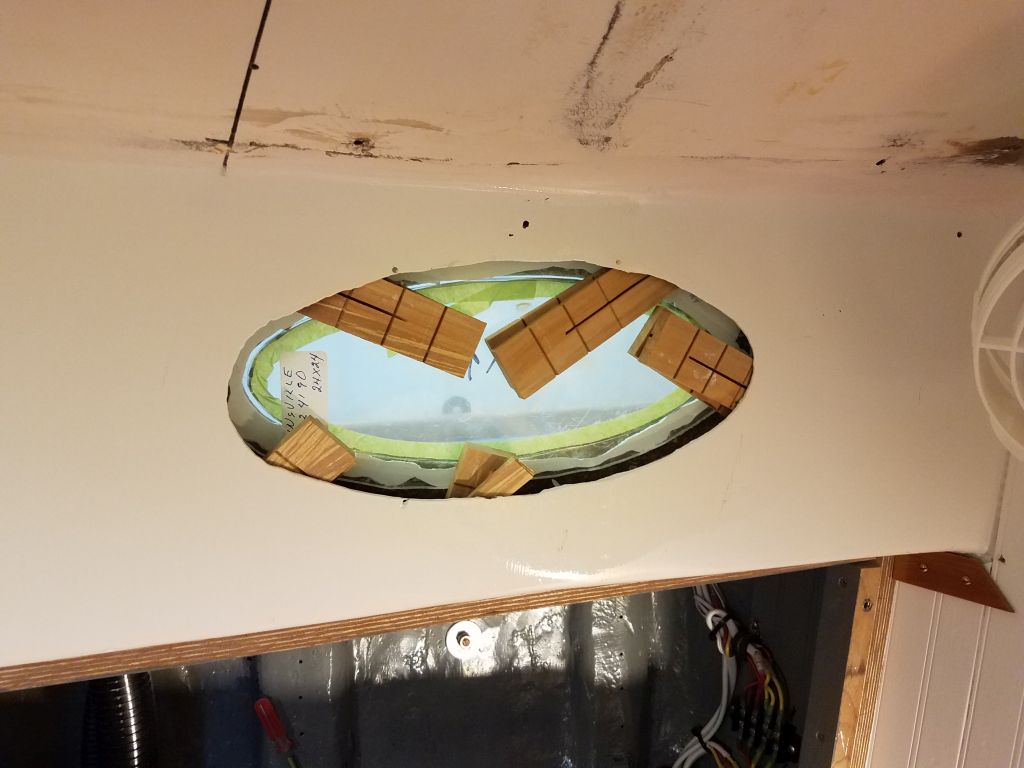
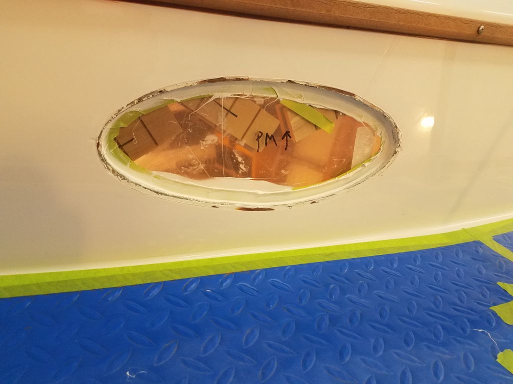
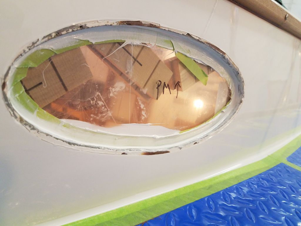
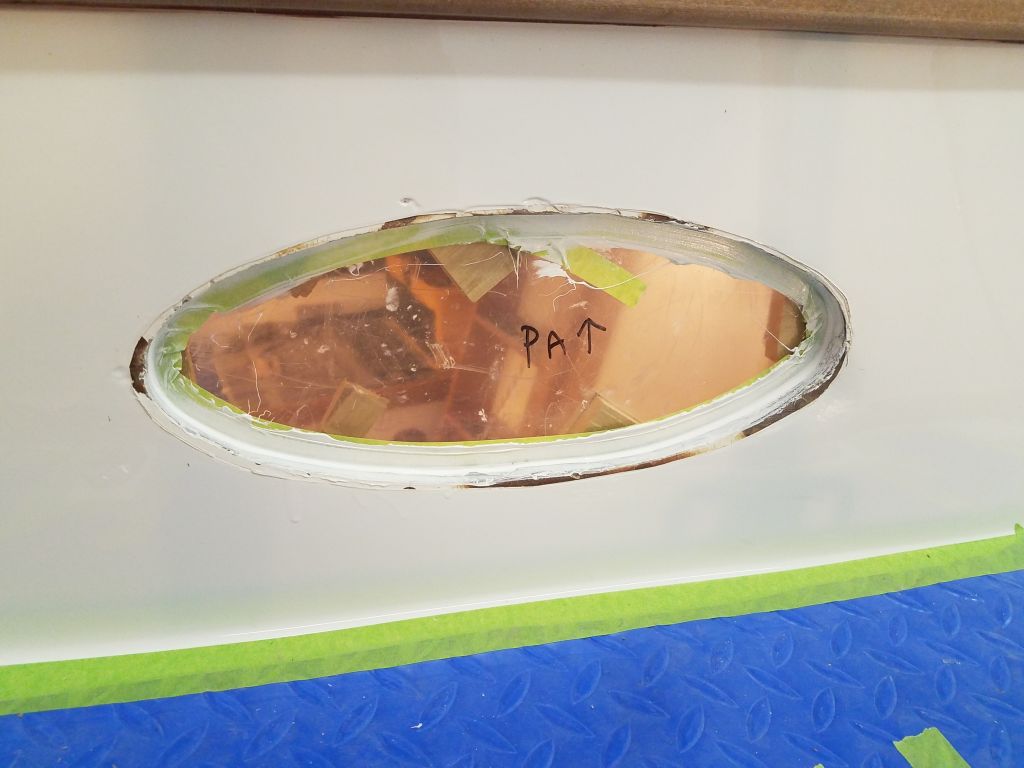
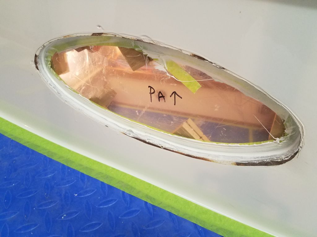
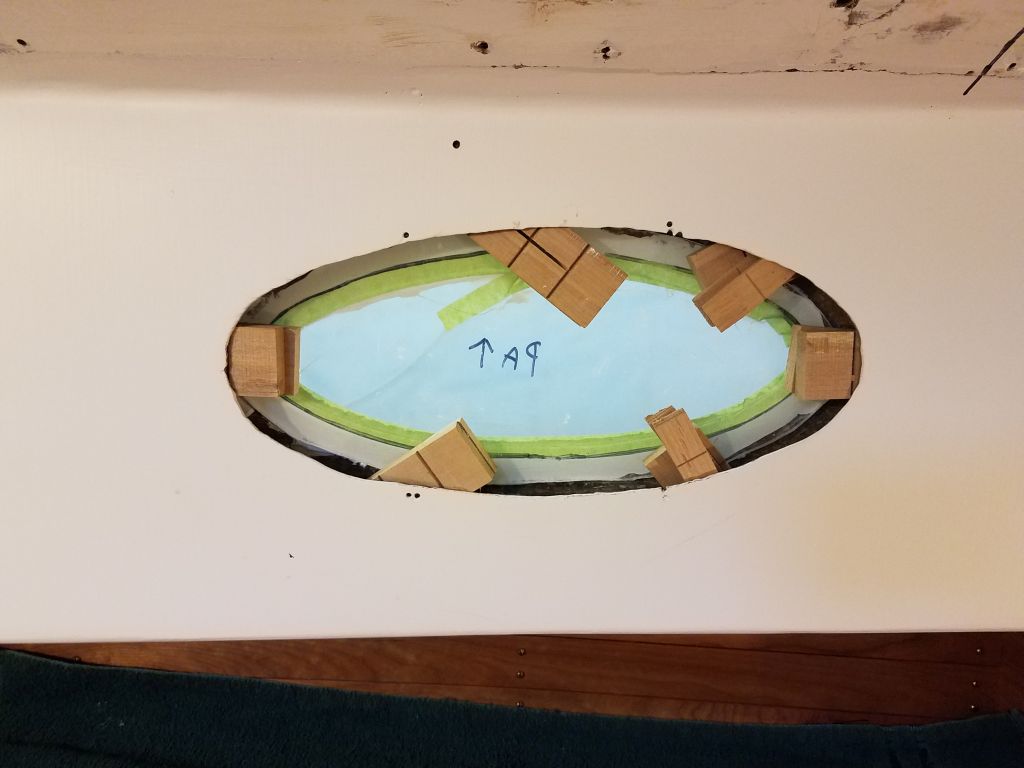
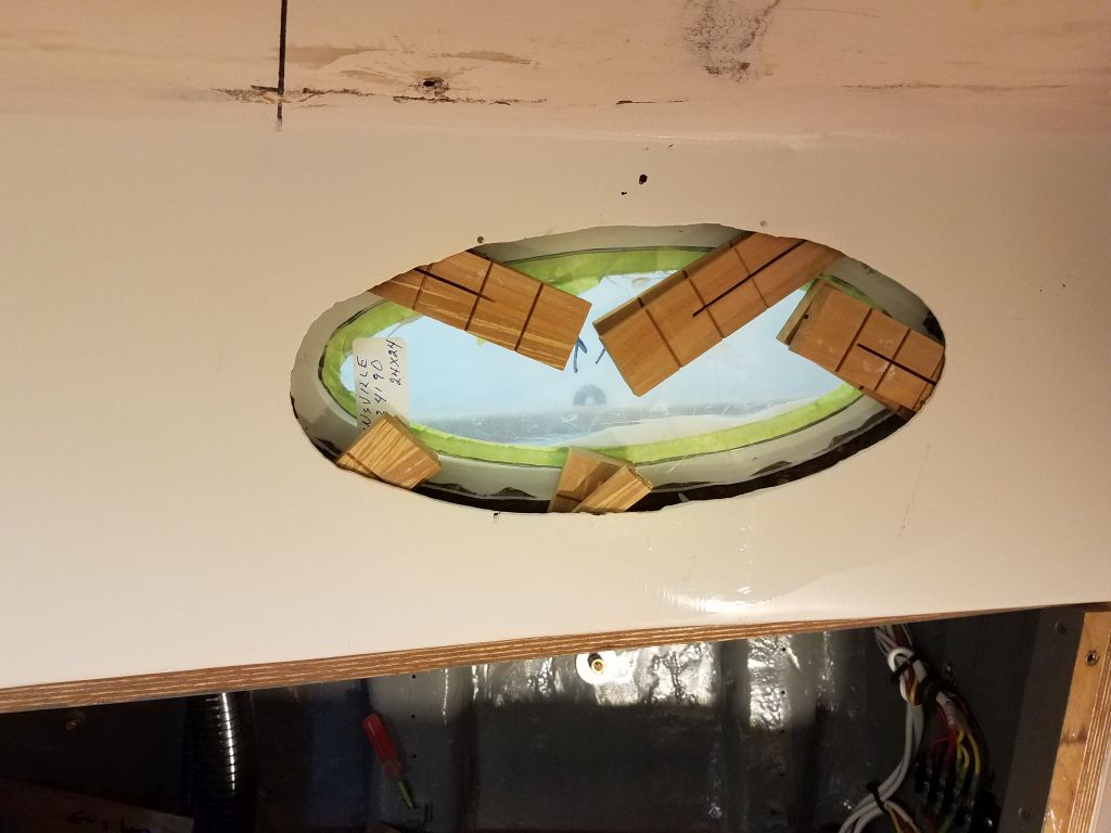
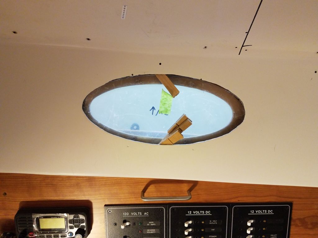
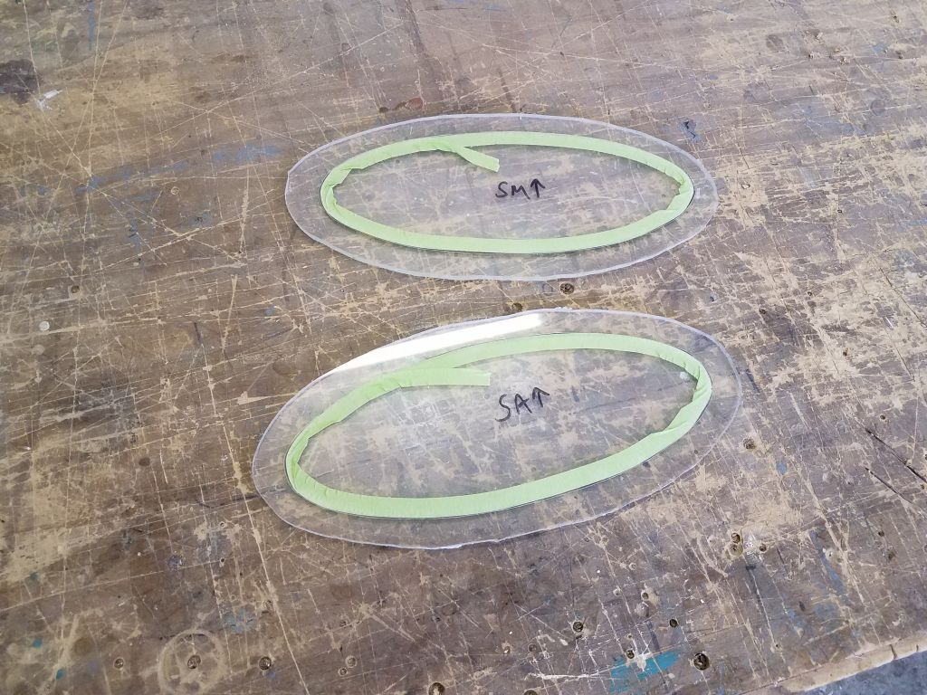
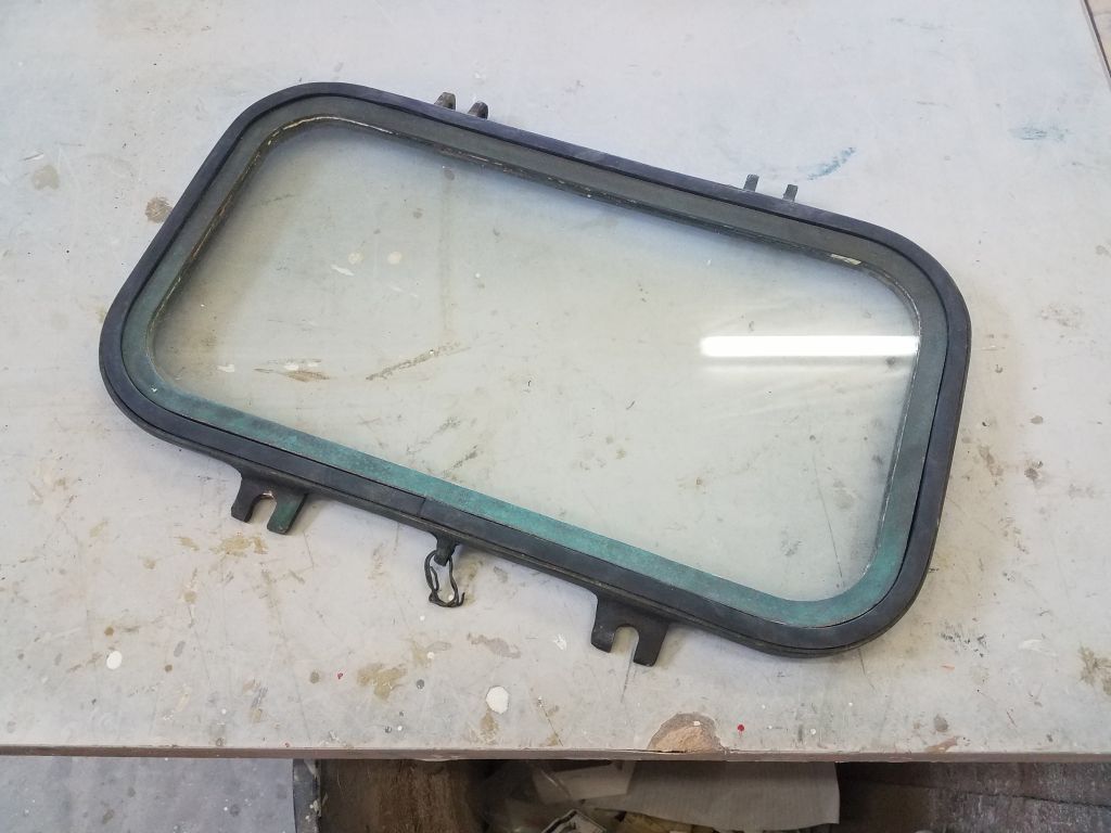
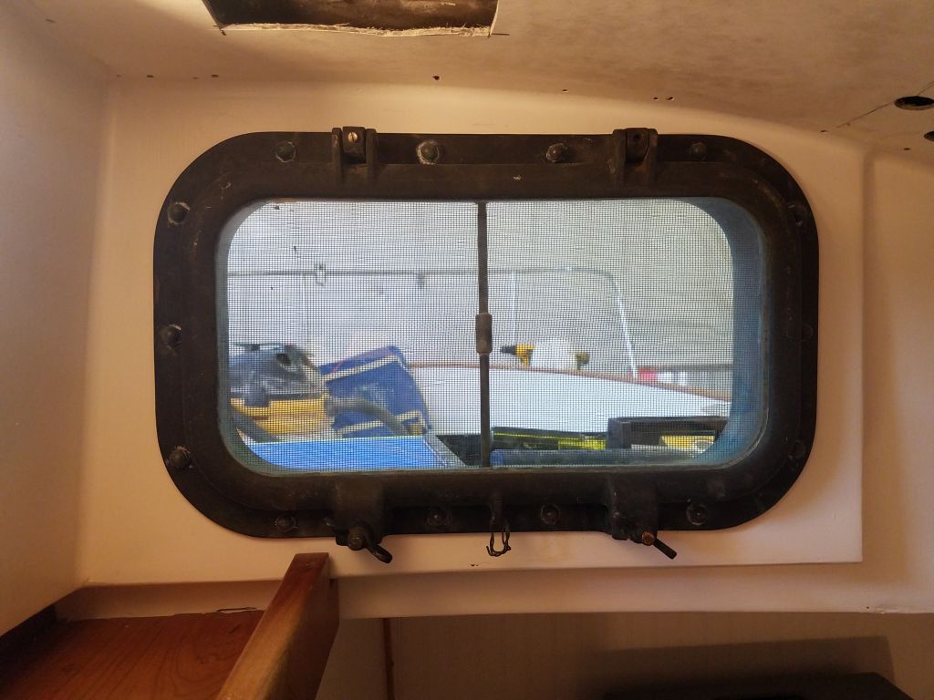
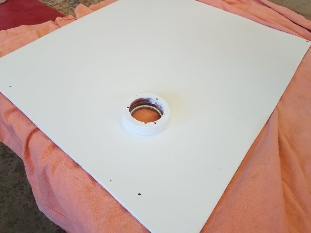
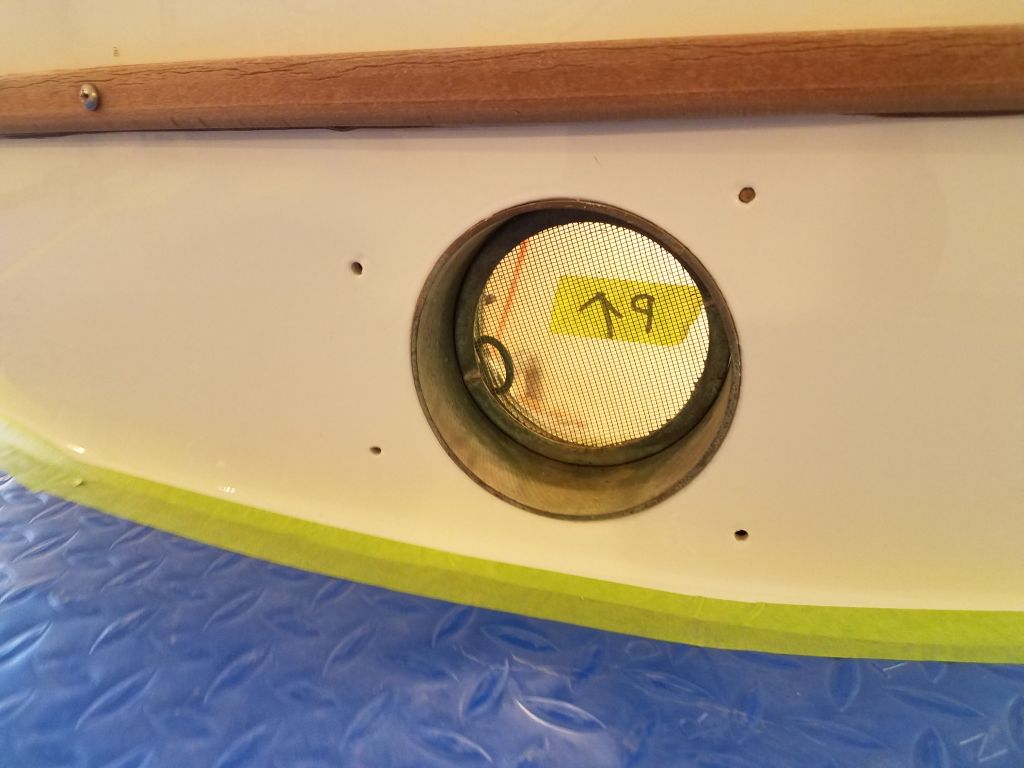
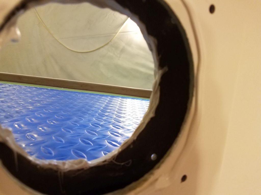
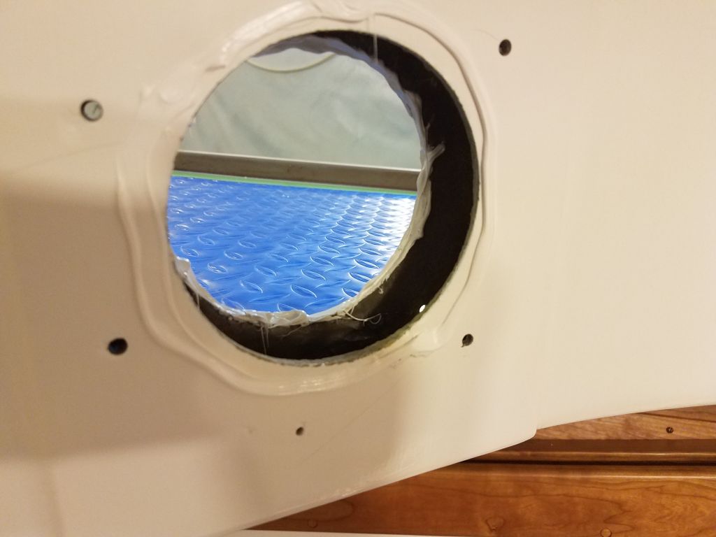
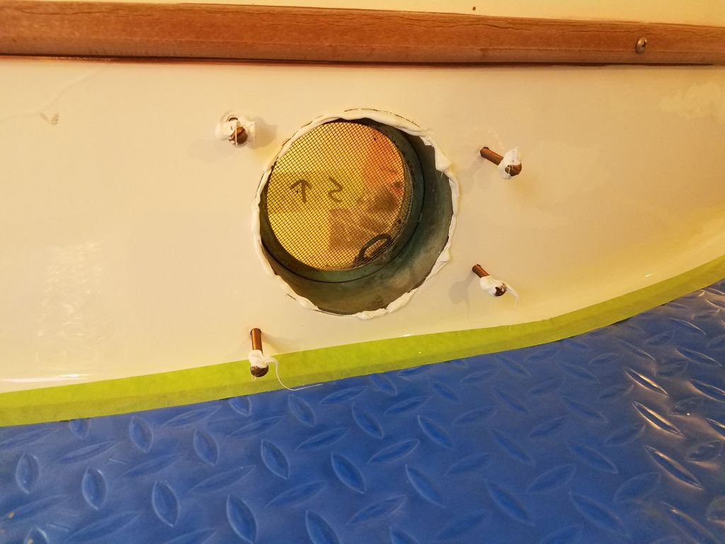
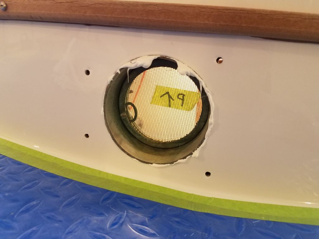
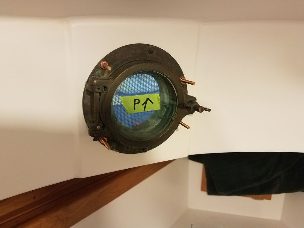
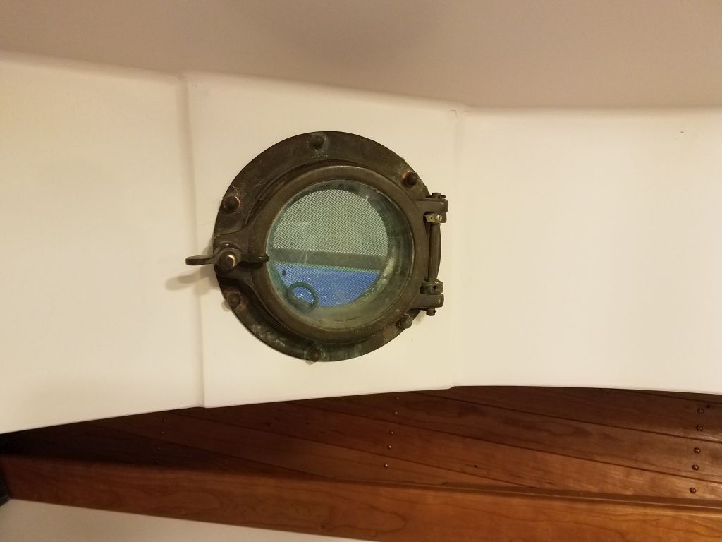
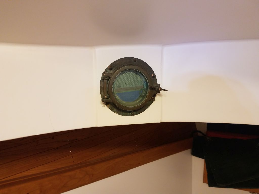
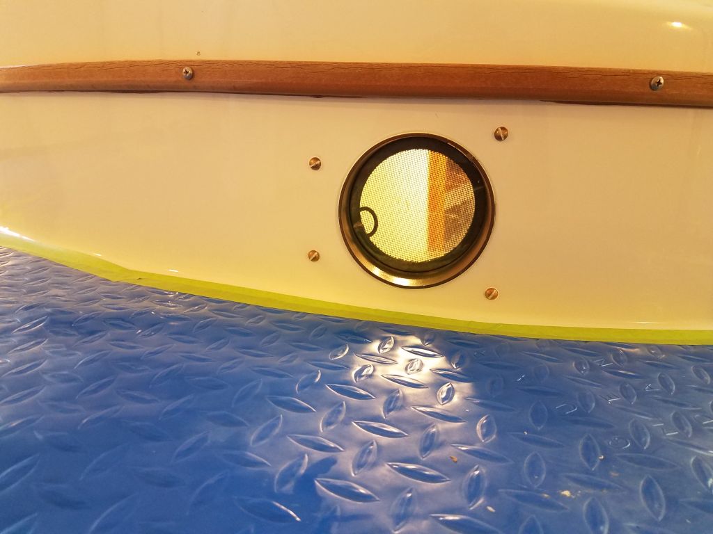
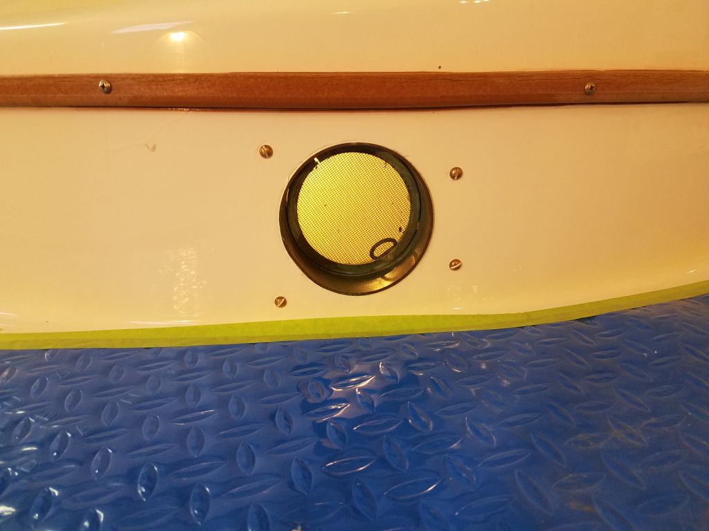
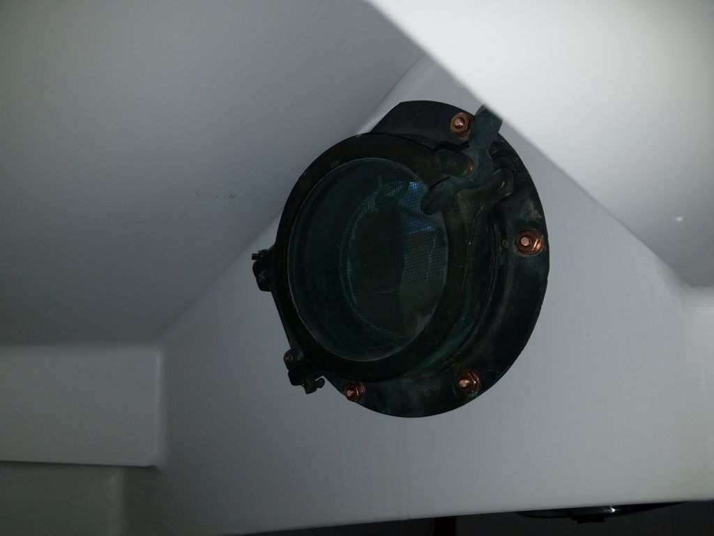
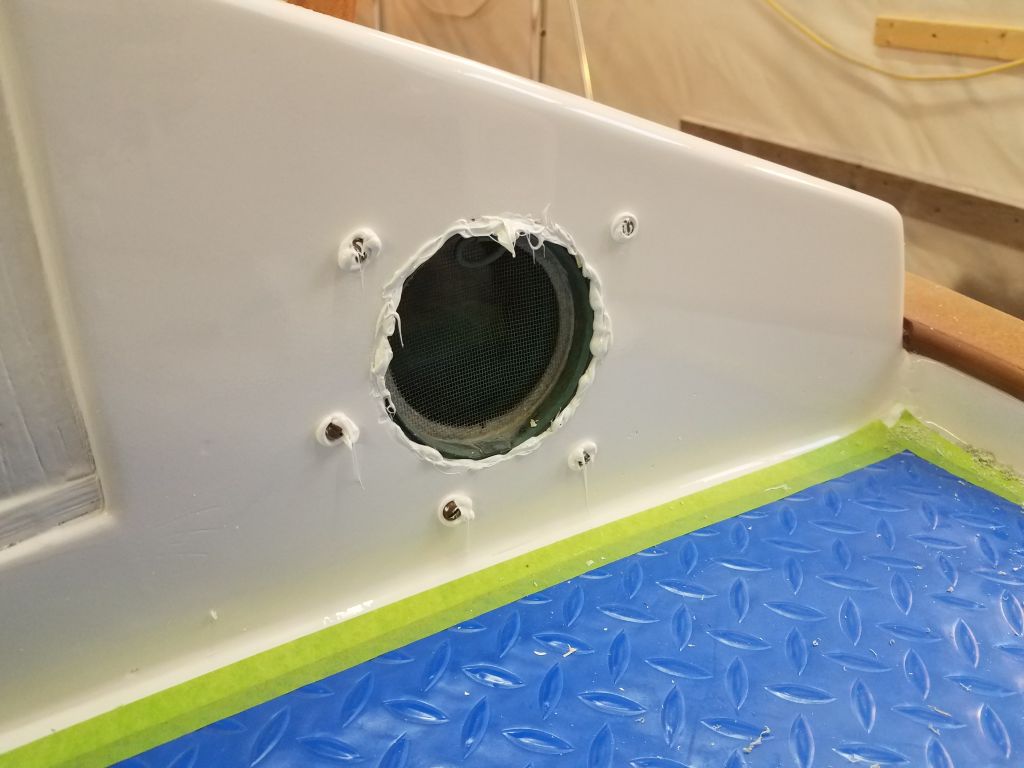
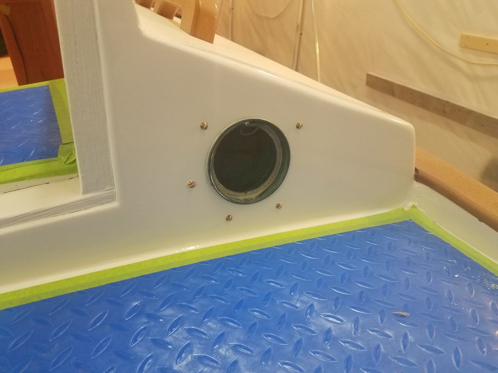
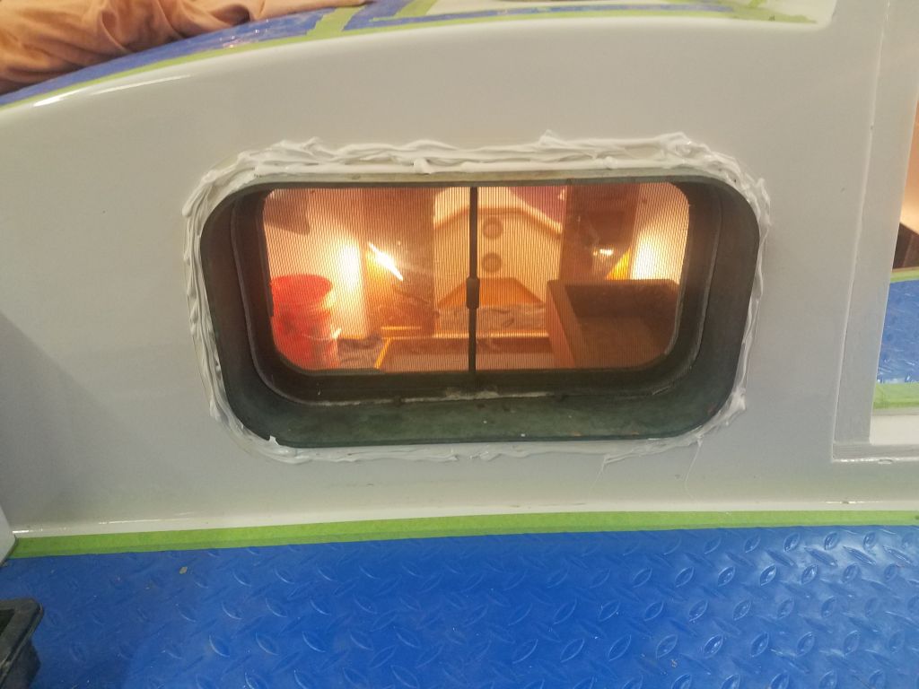
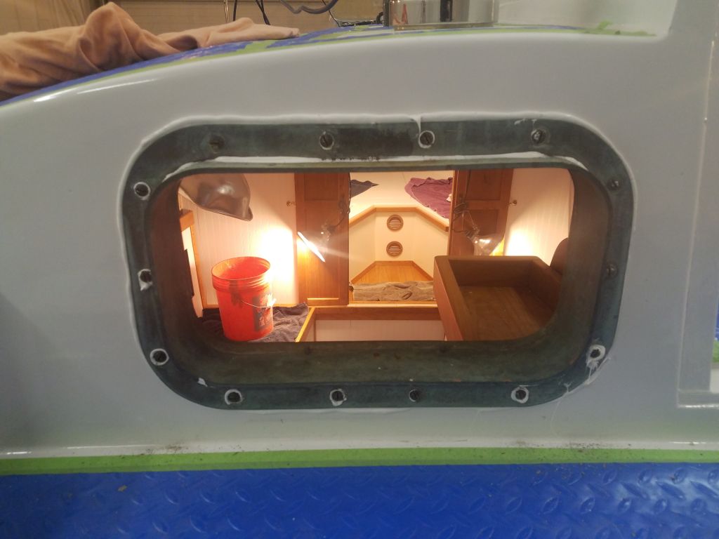
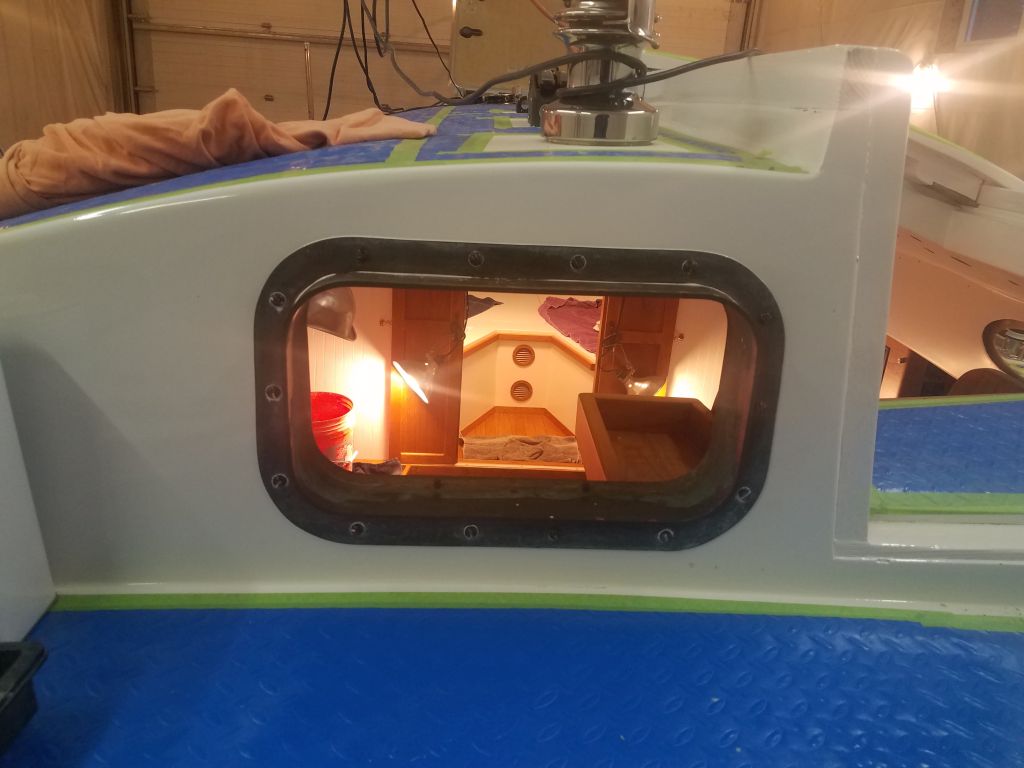
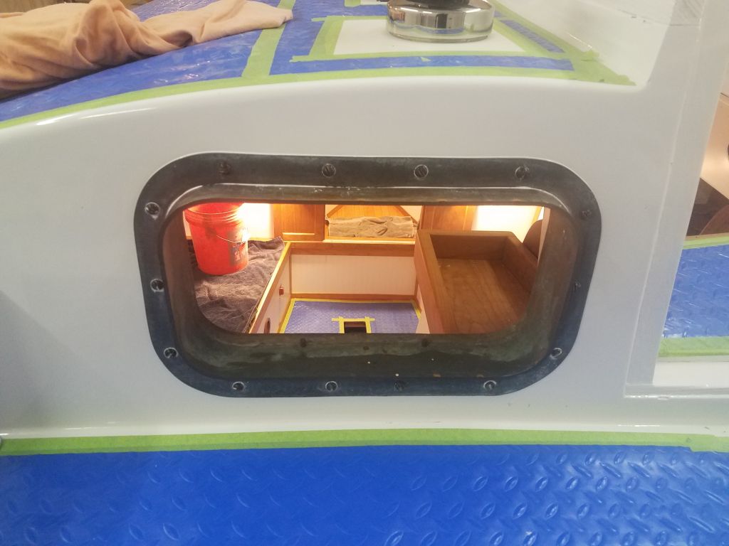
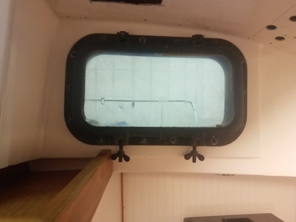
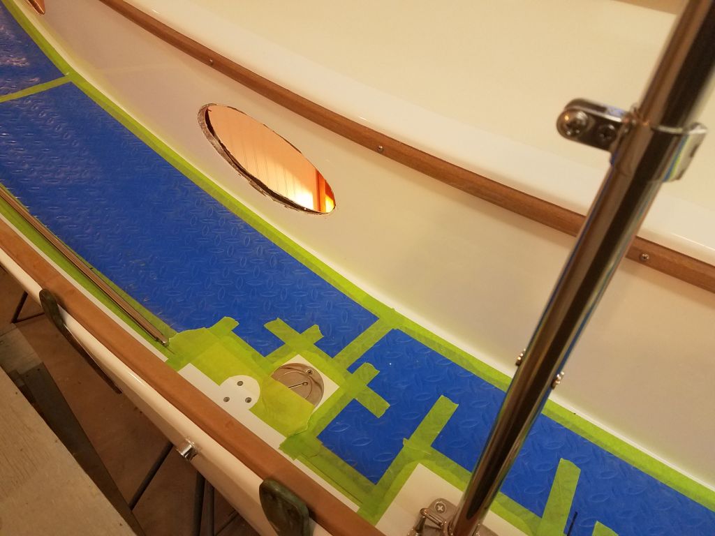
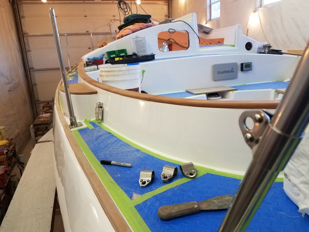
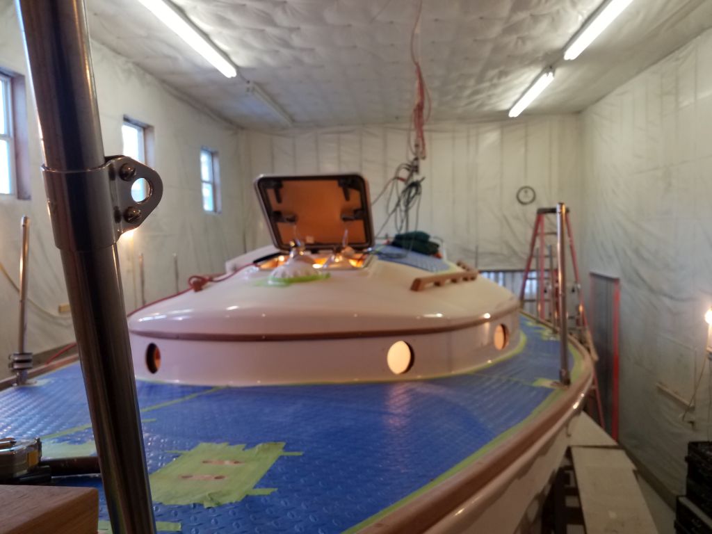
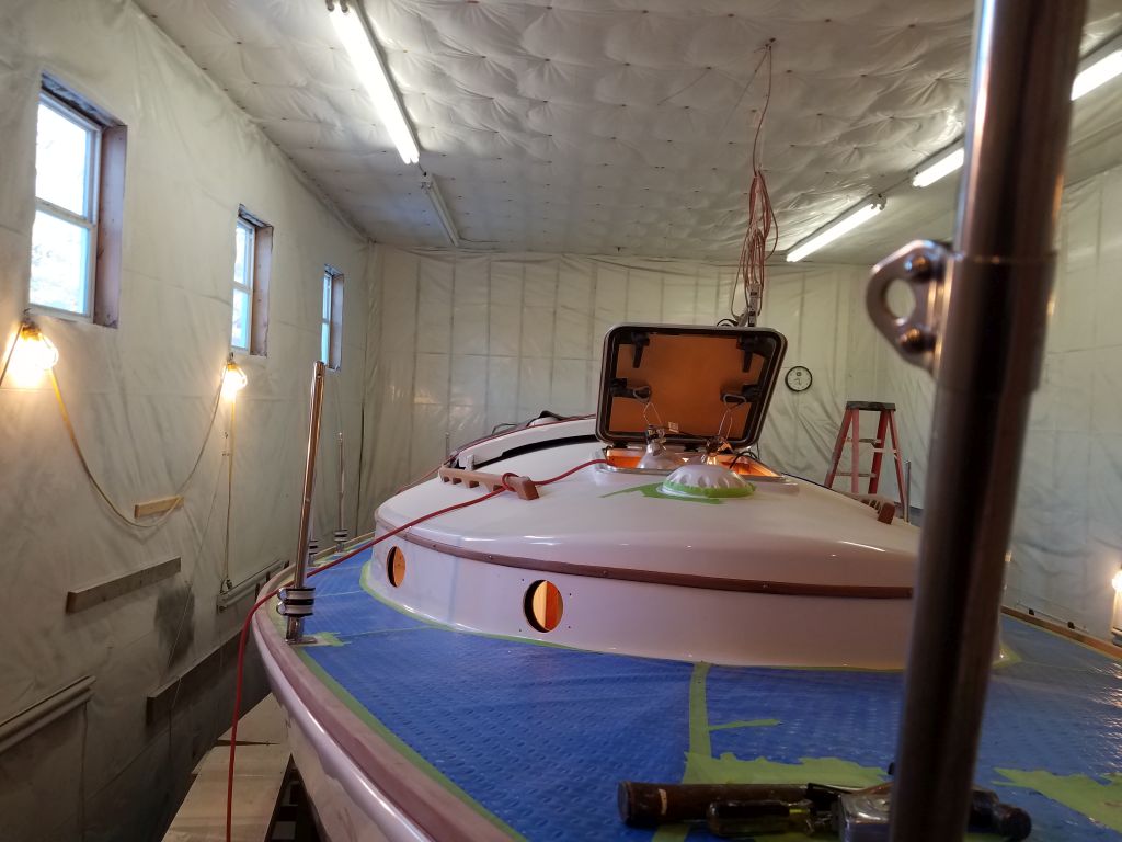
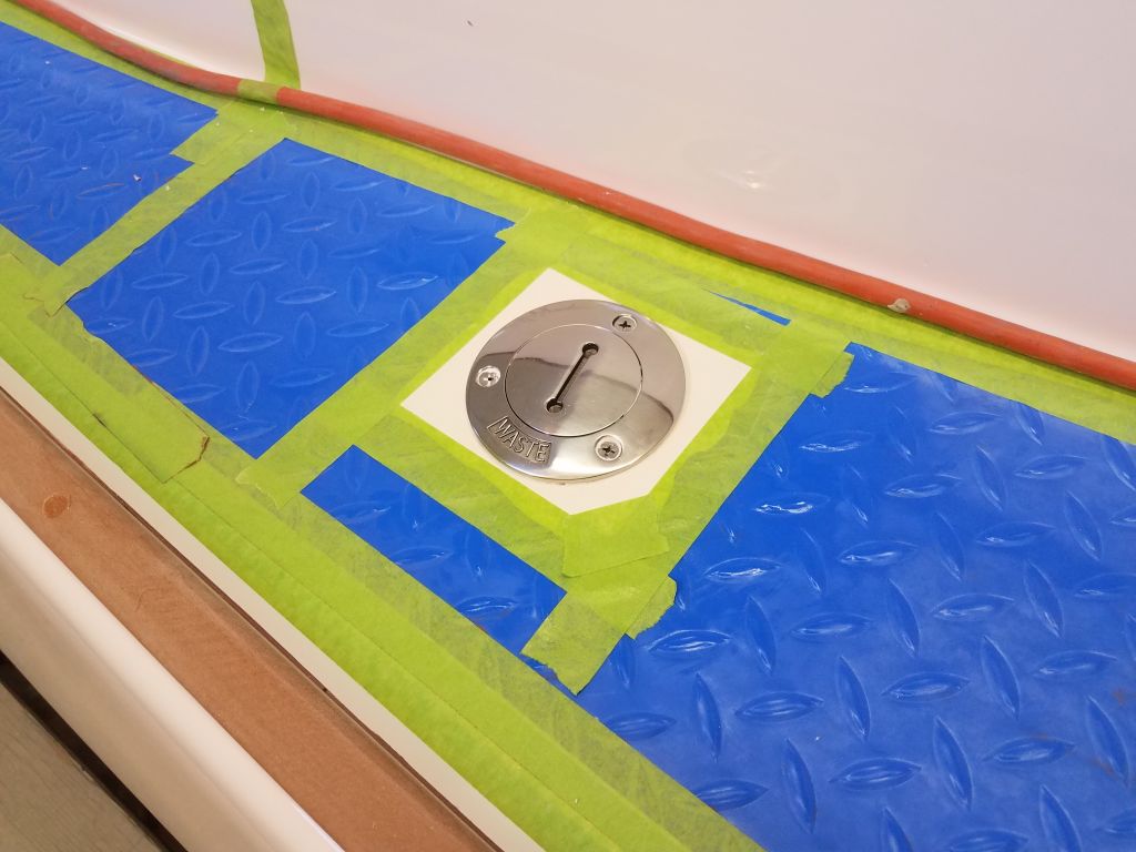
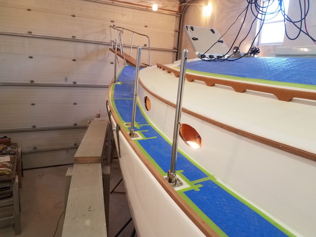
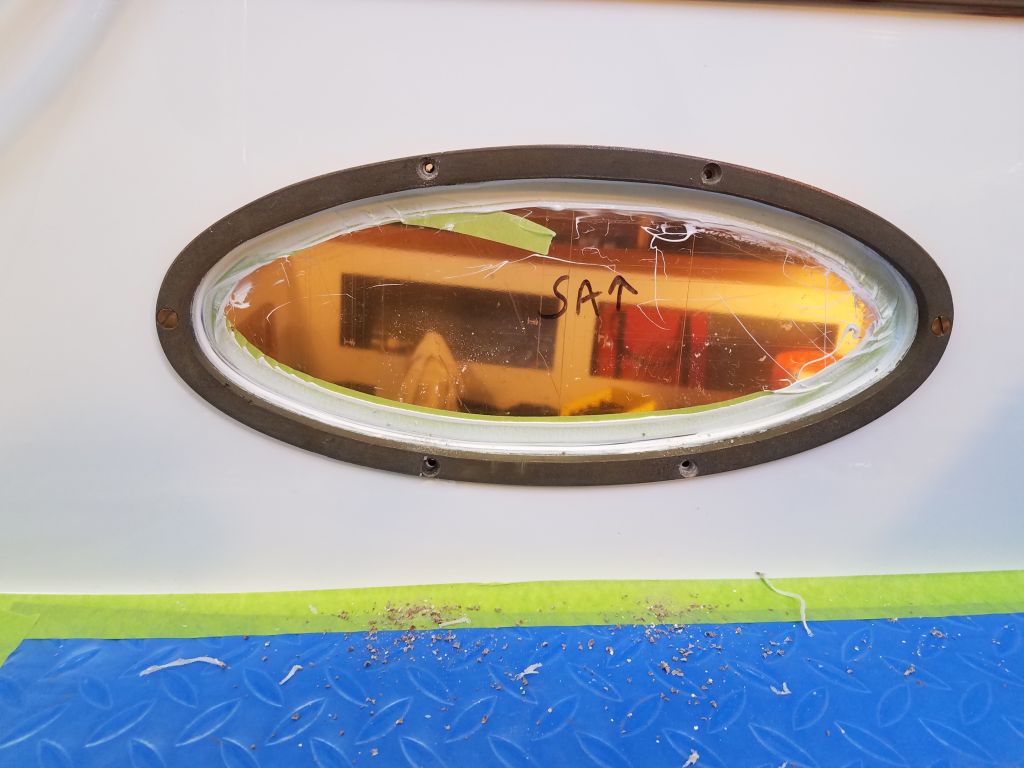
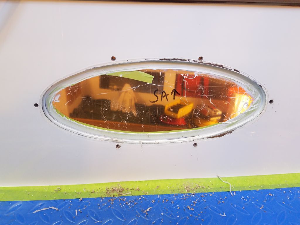
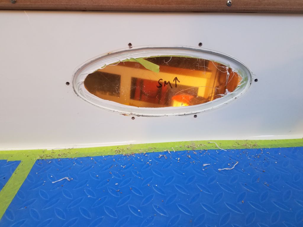
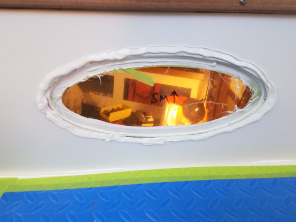
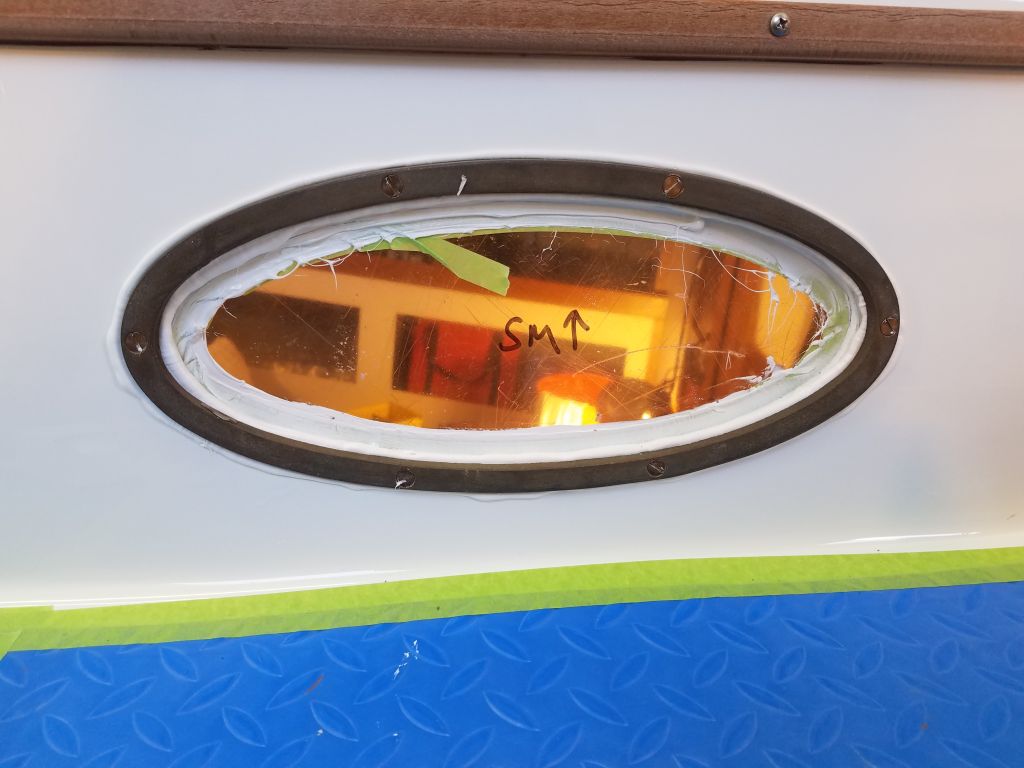
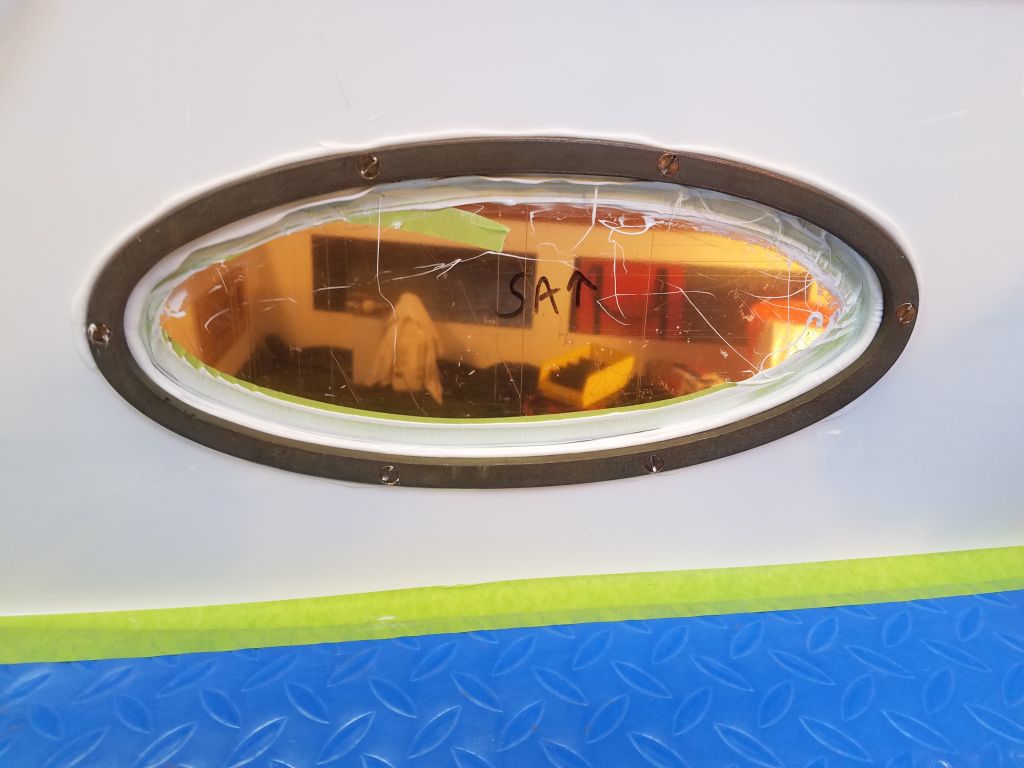
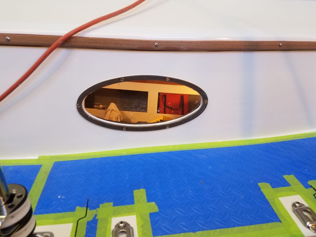
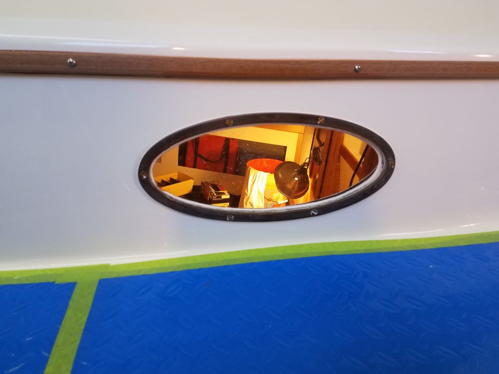
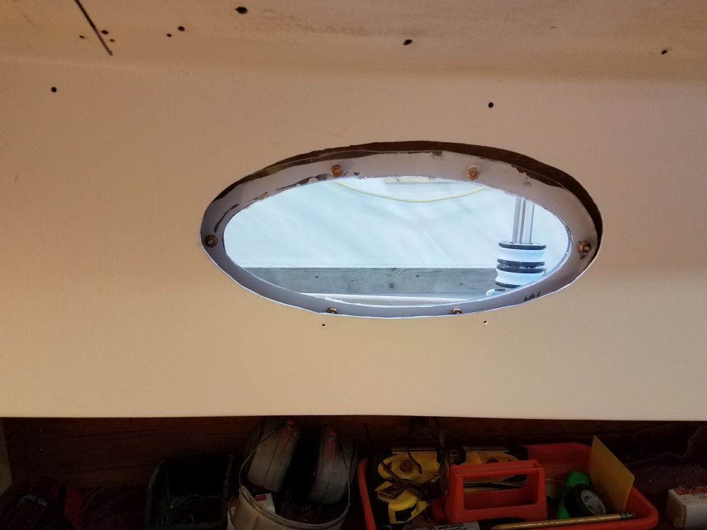
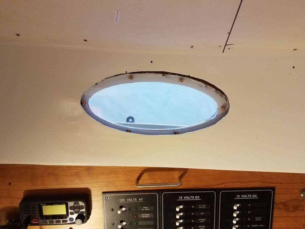
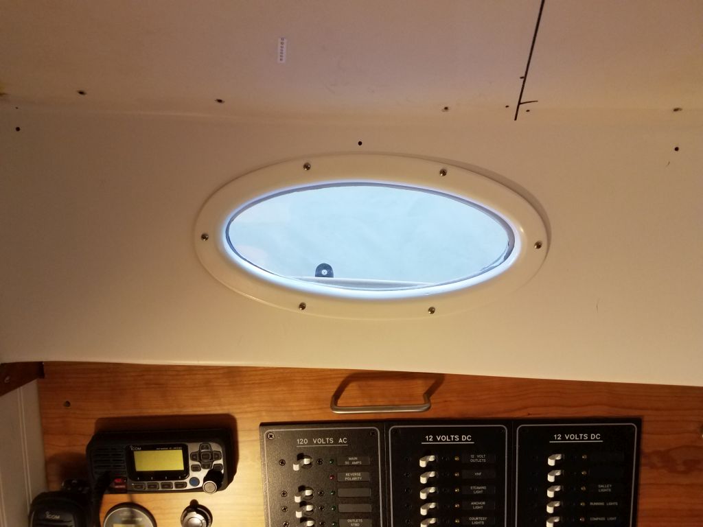
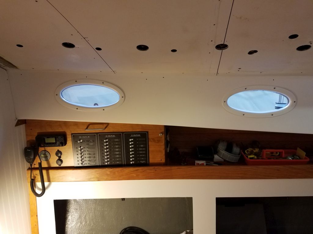
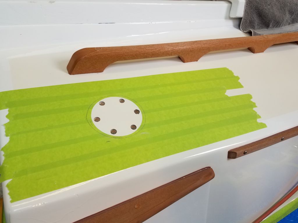
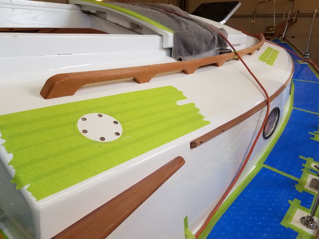
For now, though, it was time to finish up the final two deadlights on the starboard side.  The lenses had had a couple days to cure in place, so I removed the wedges and protective plastic from inside, then, back outside, laid out and prepared the screwholes for the bronze trim rings before installing them and finishing them off as I’d done earlier with the other four.

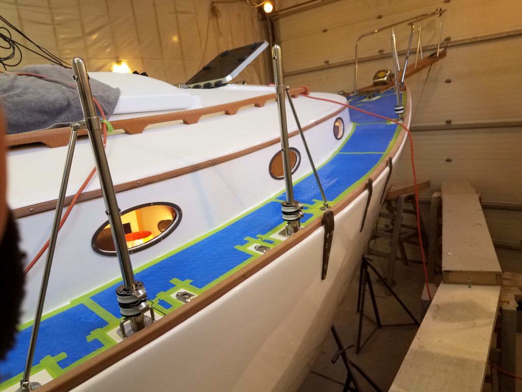
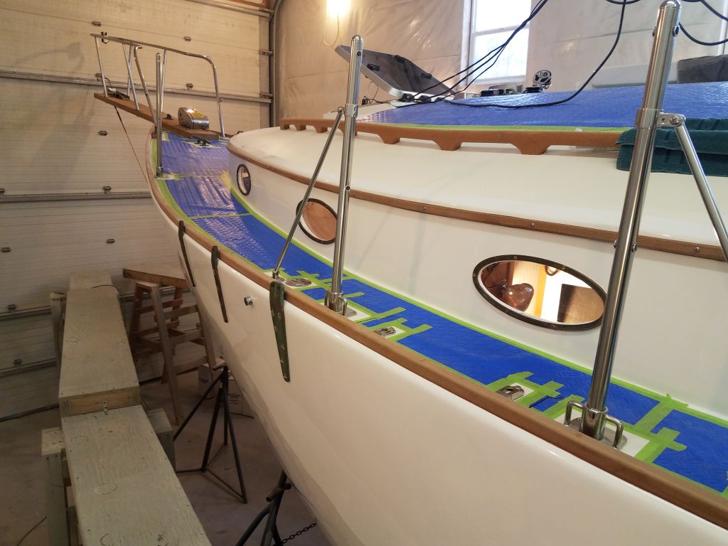
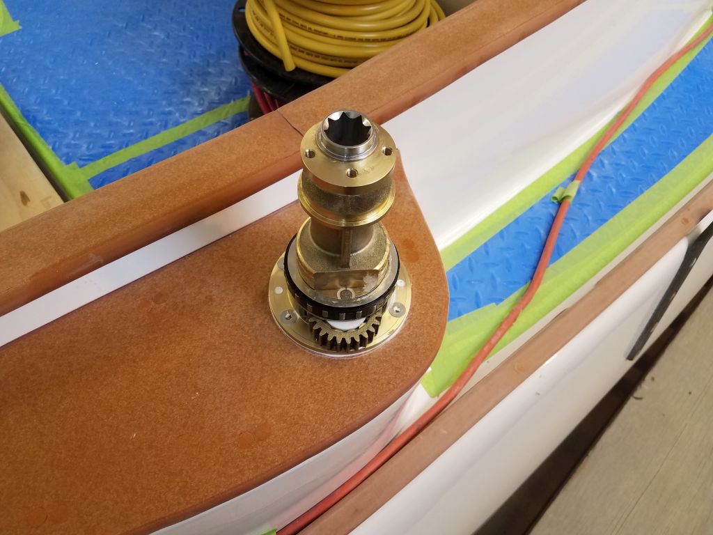
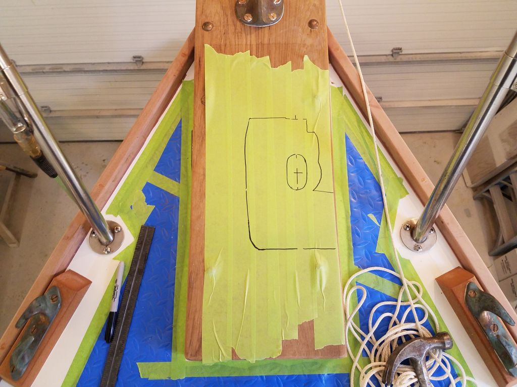
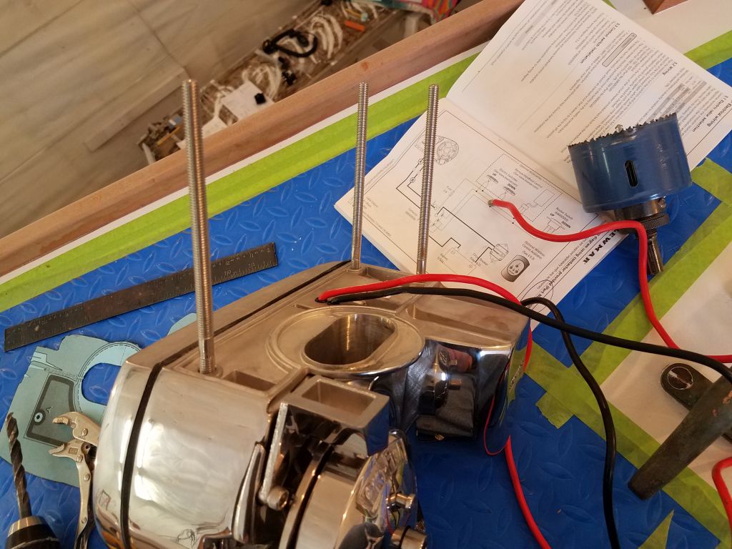
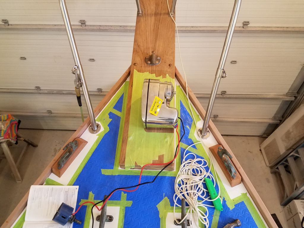
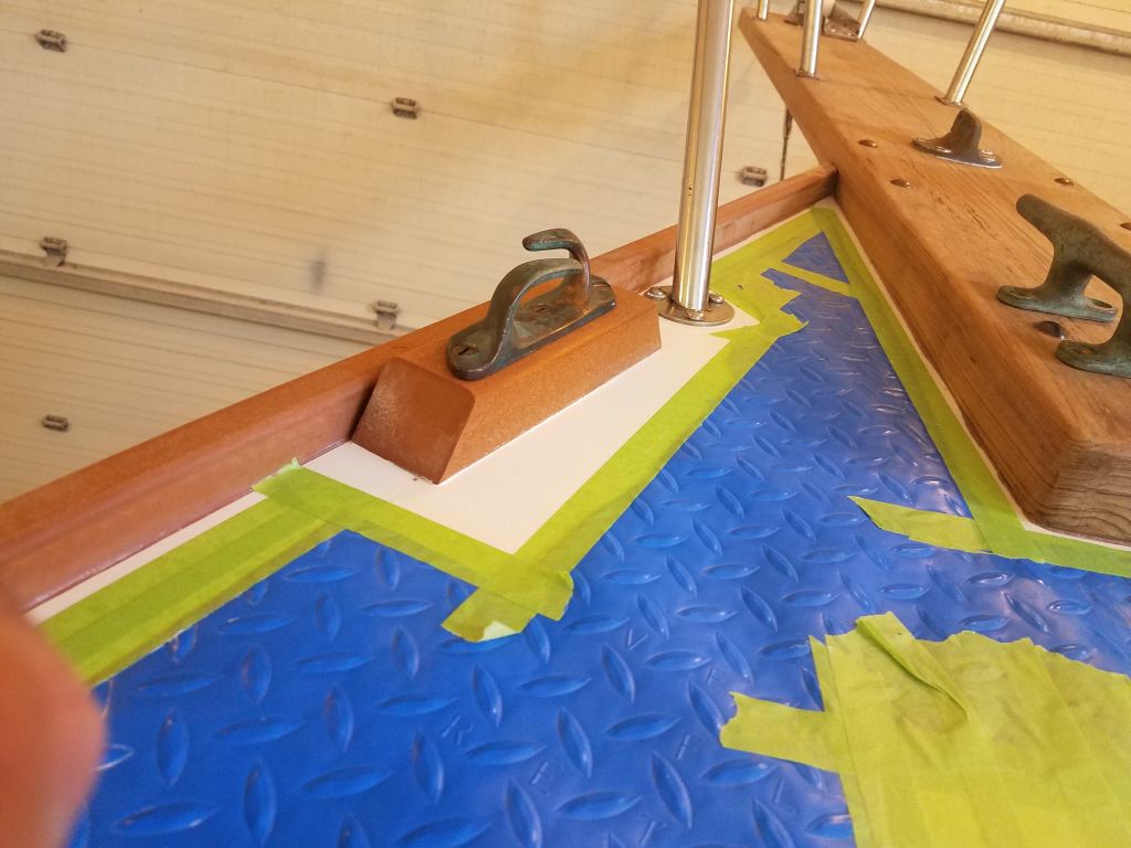
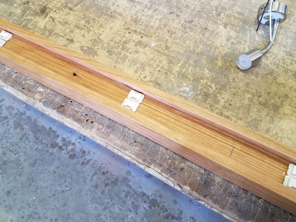
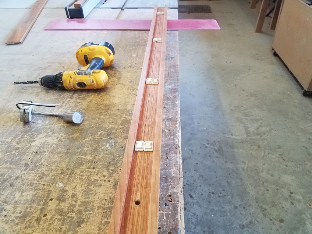
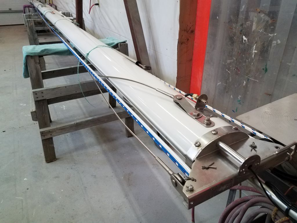
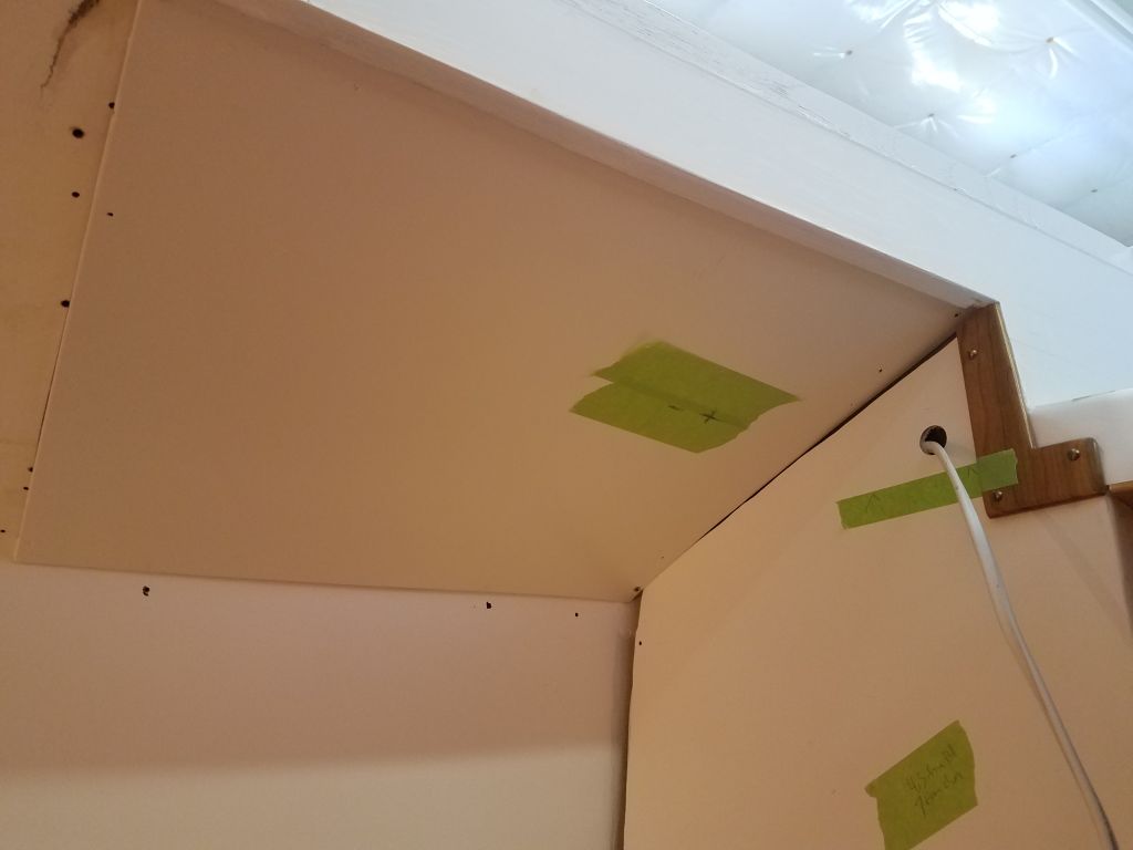
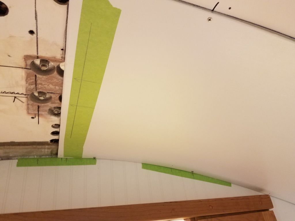
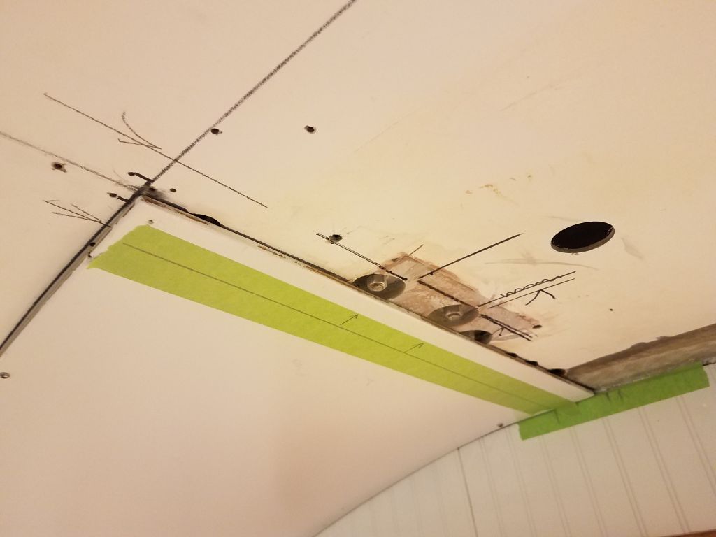
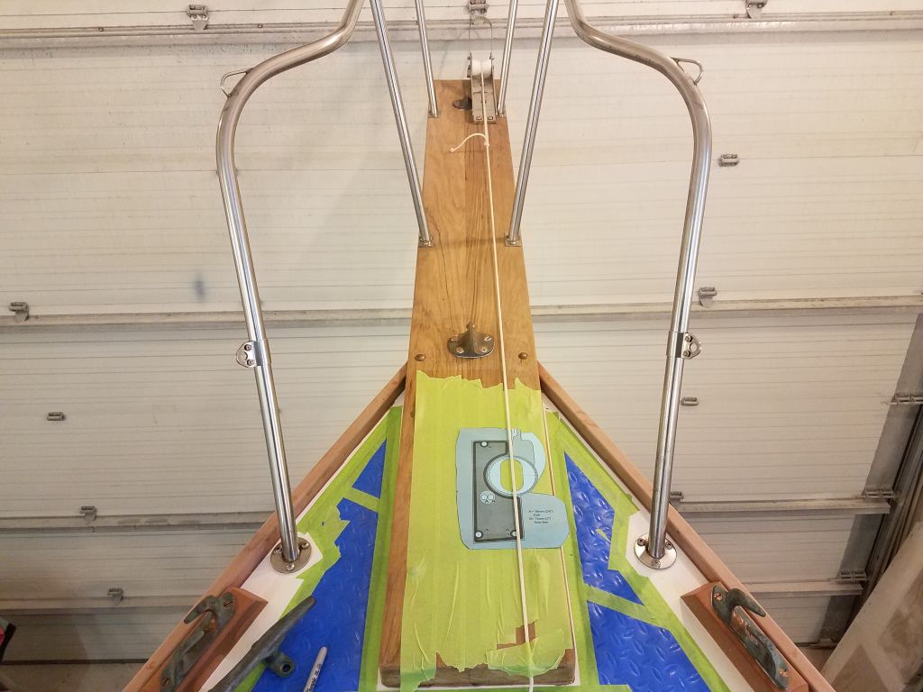
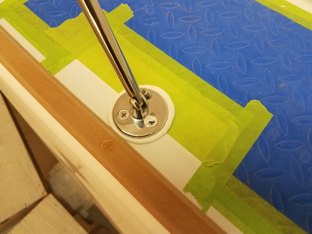
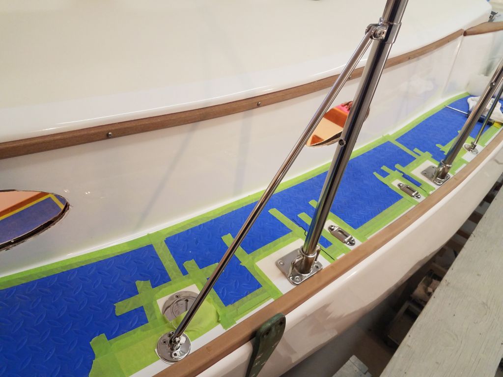
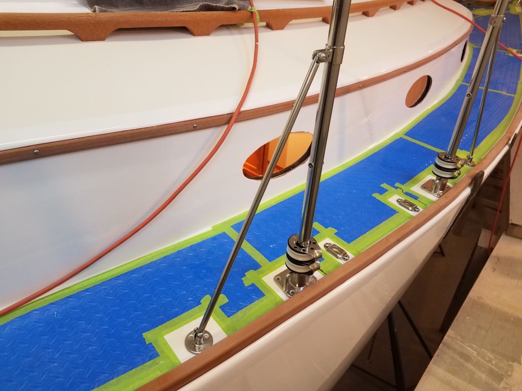
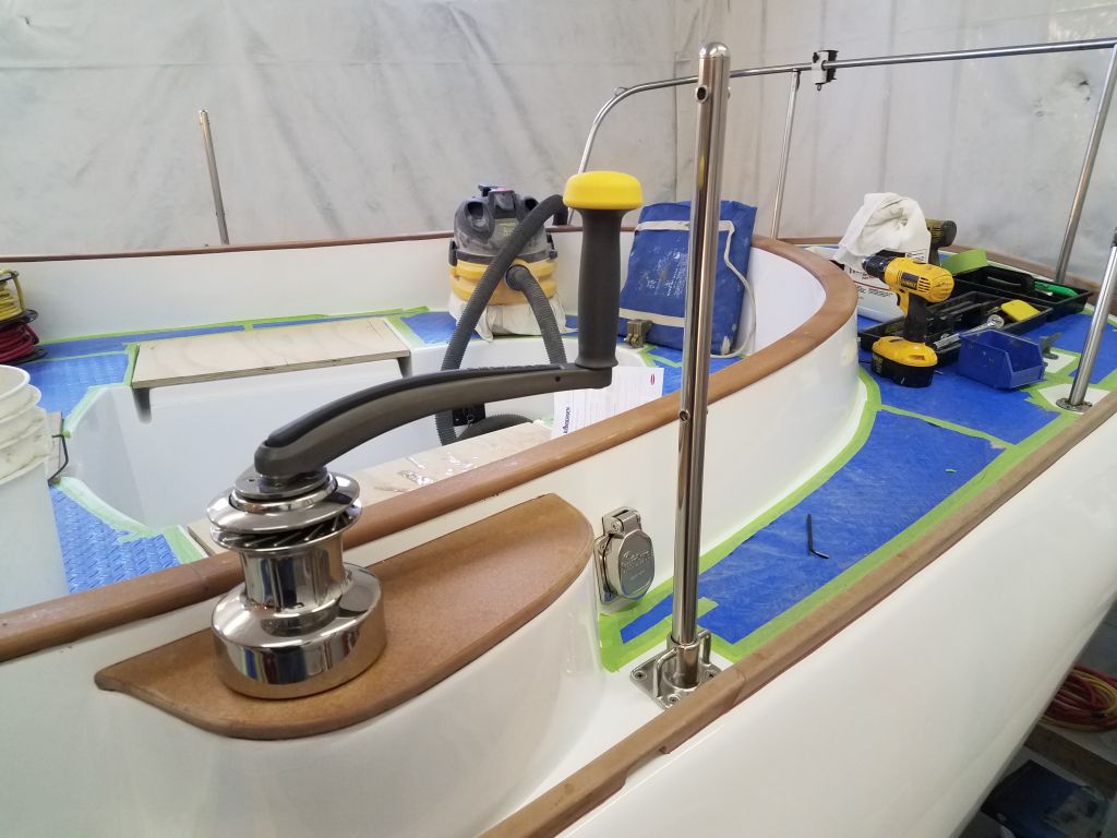
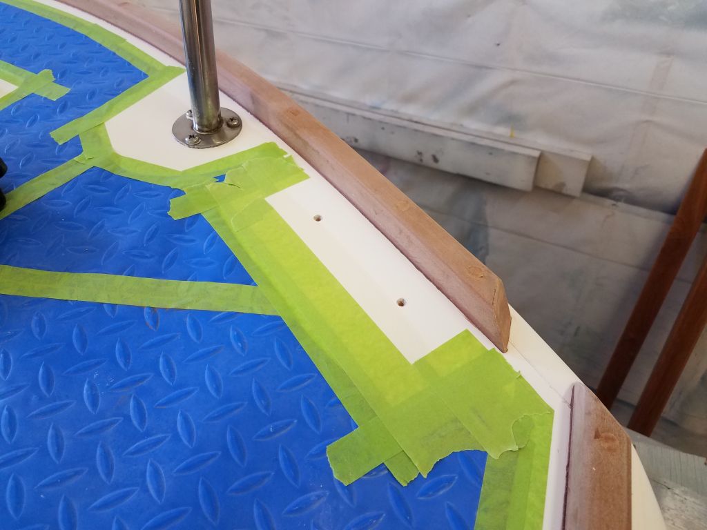
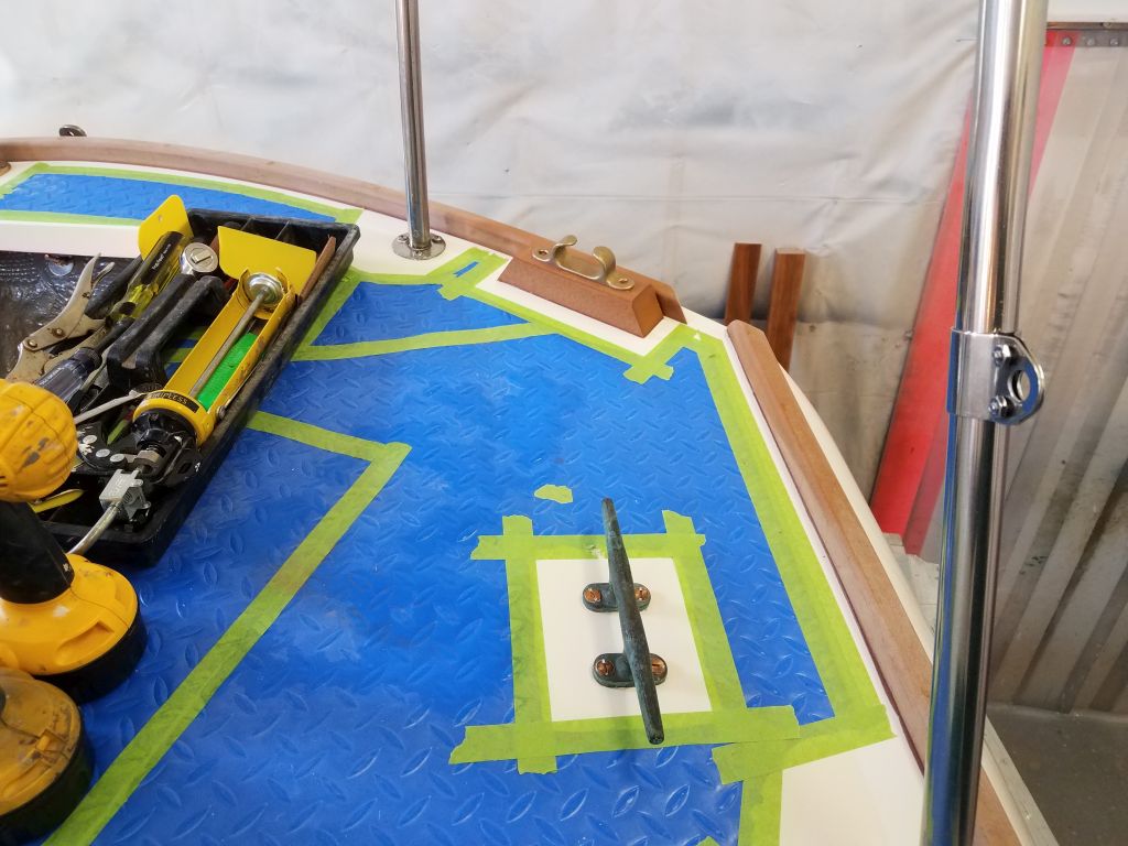
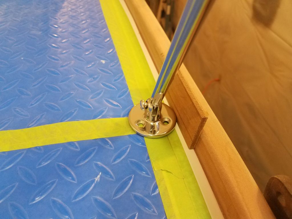
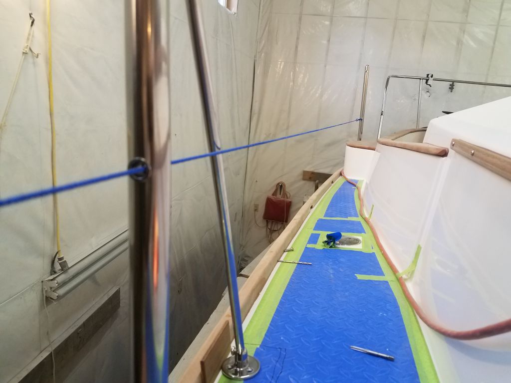
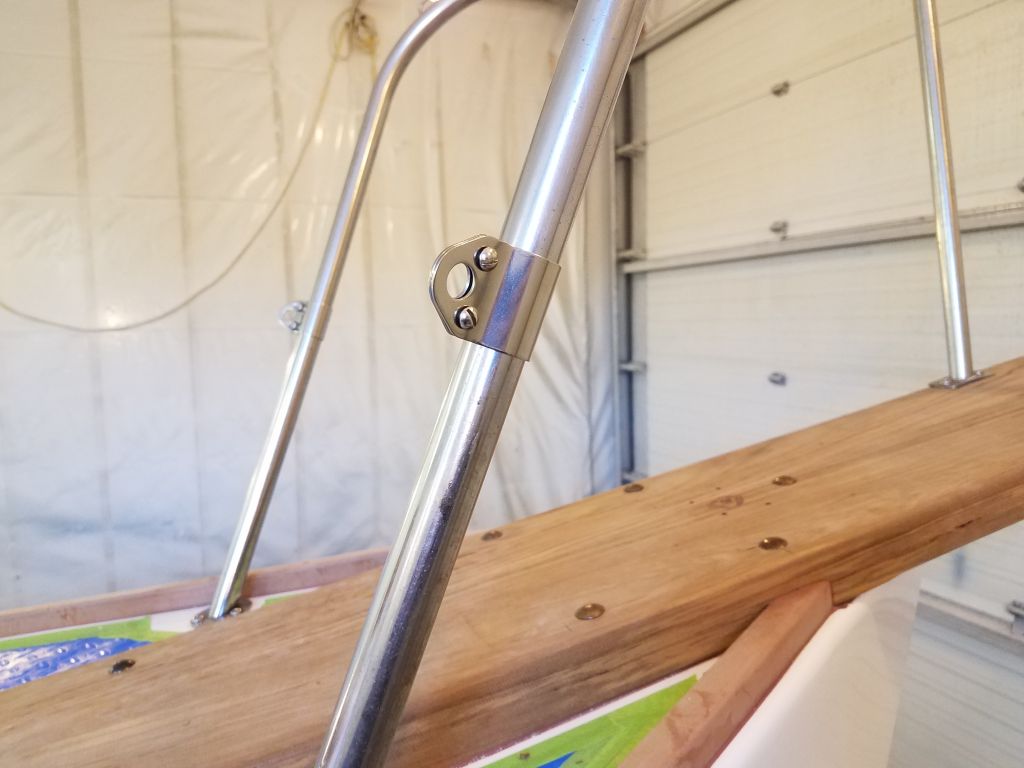
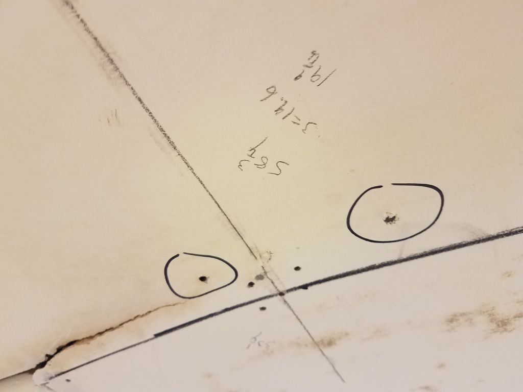
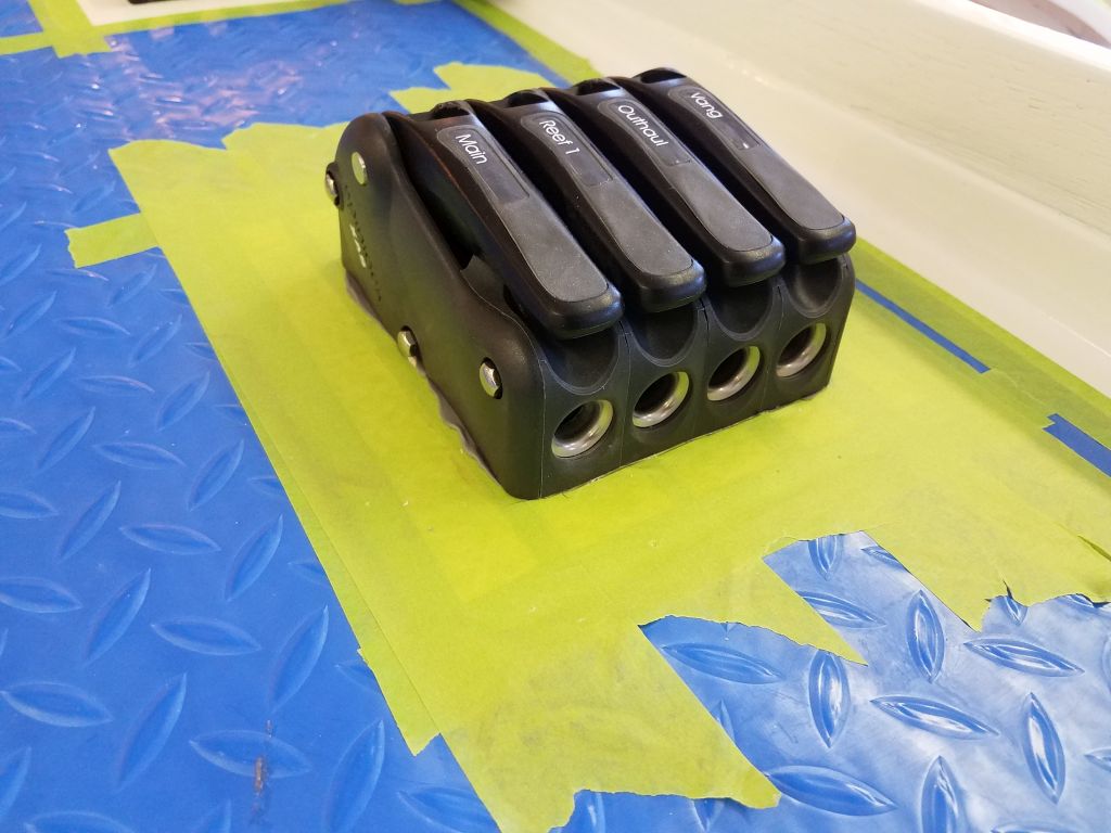
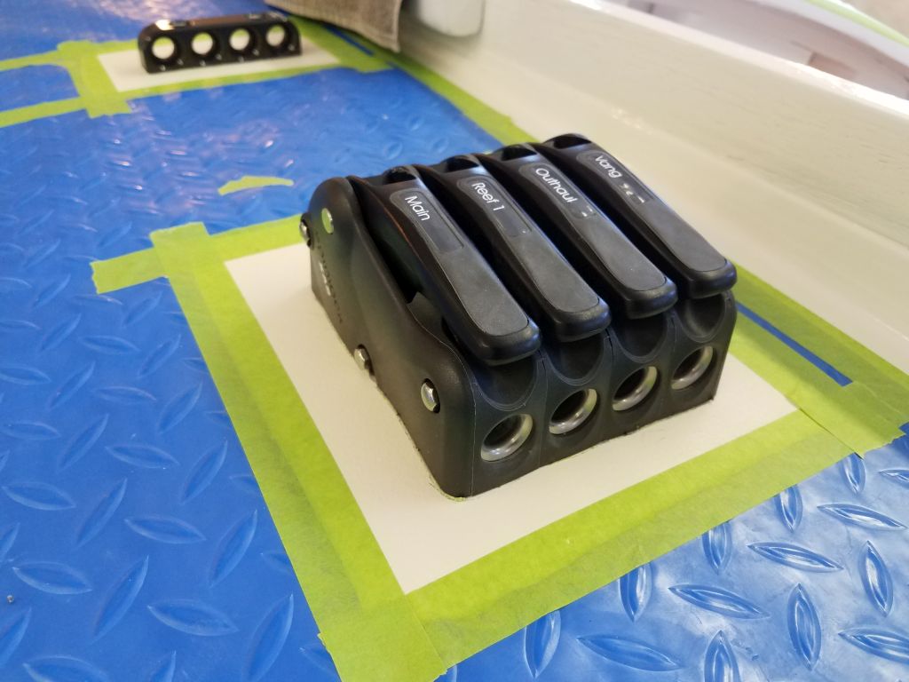
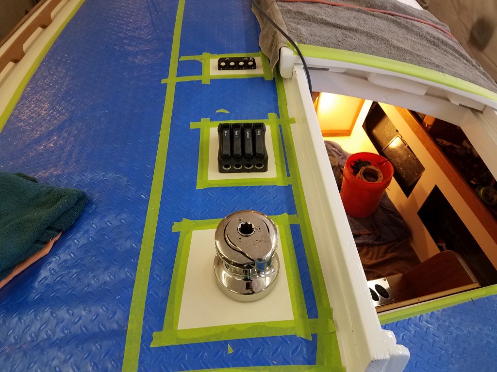
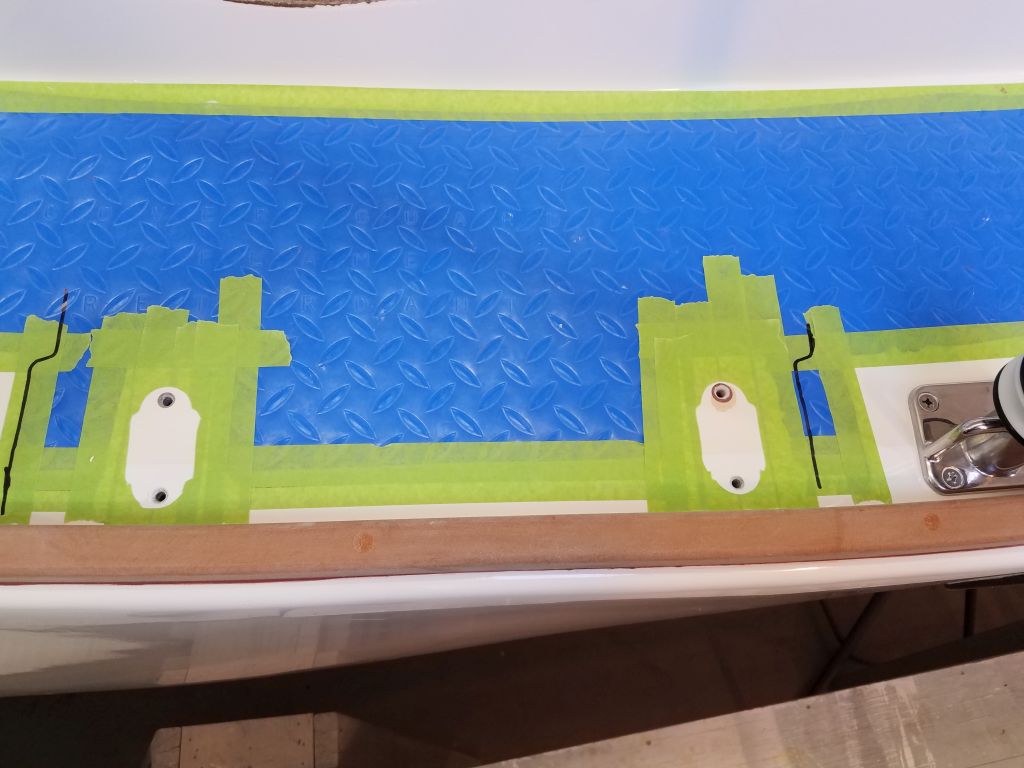
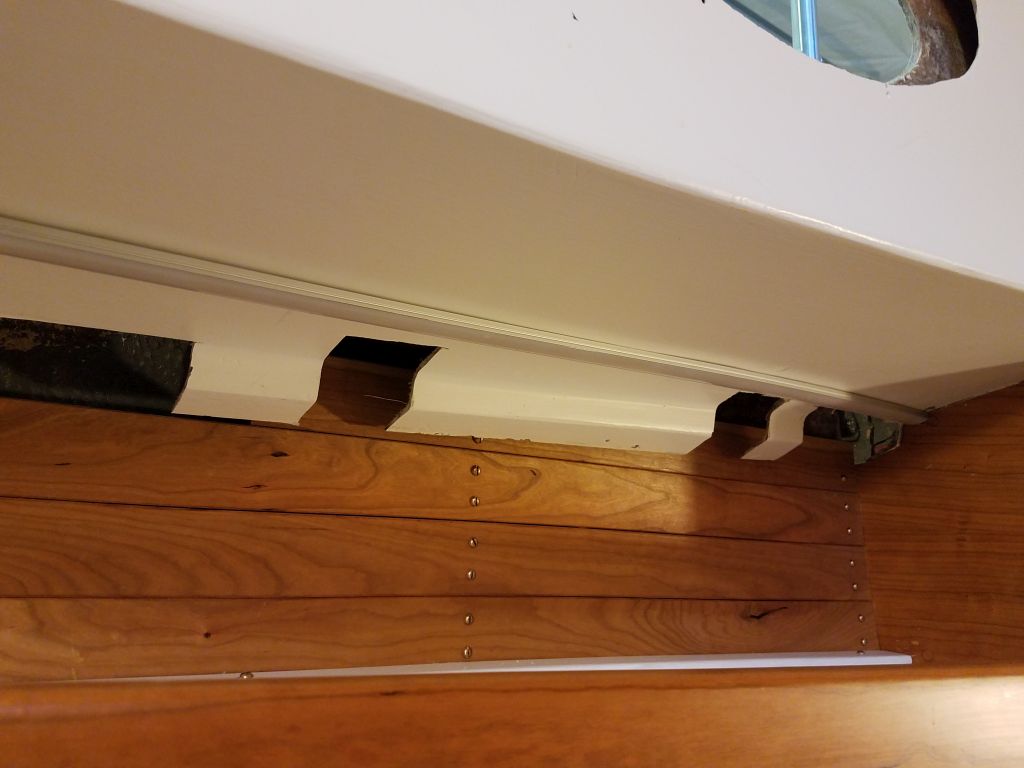
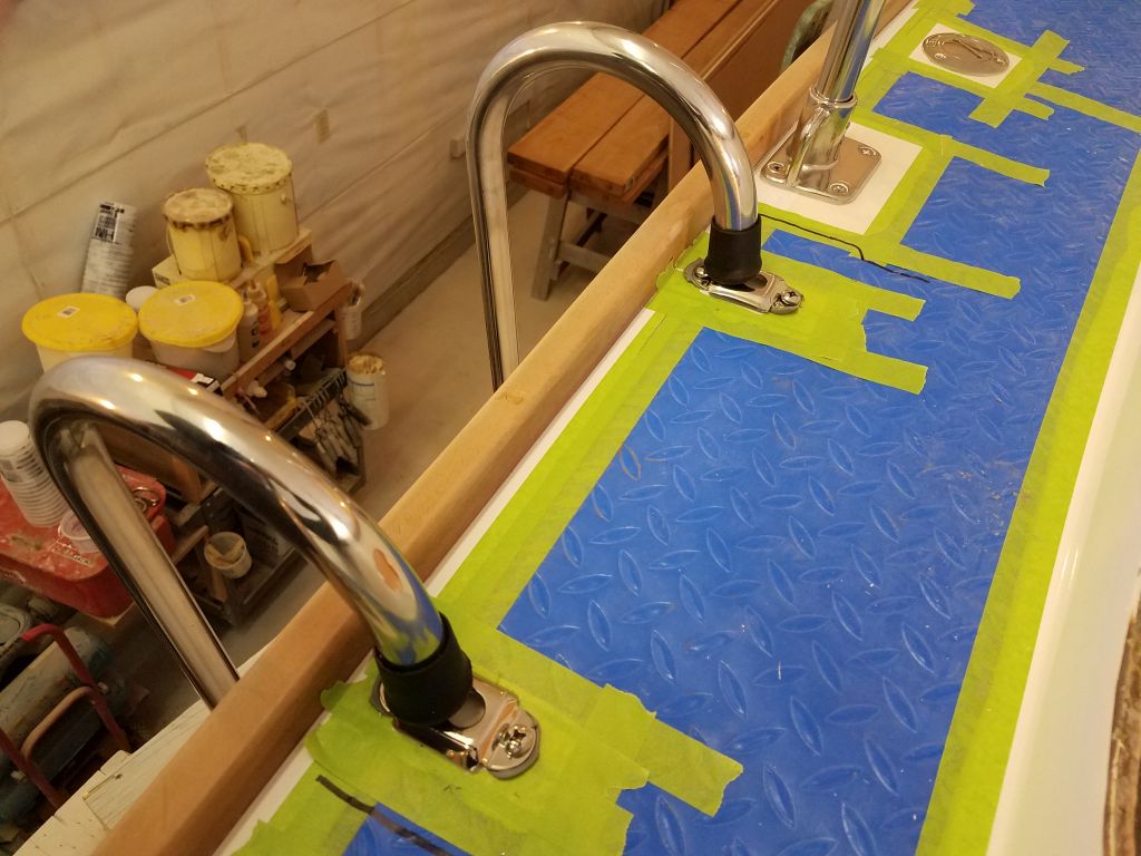
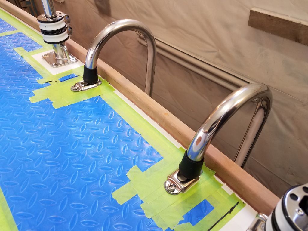
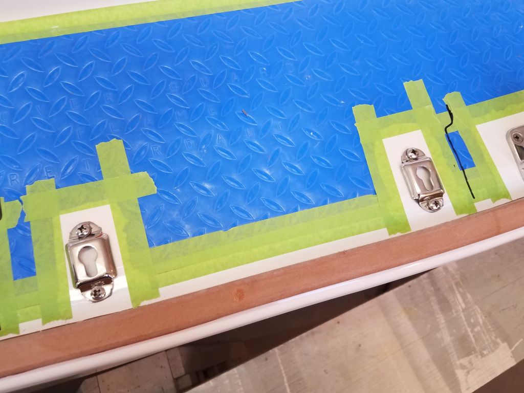
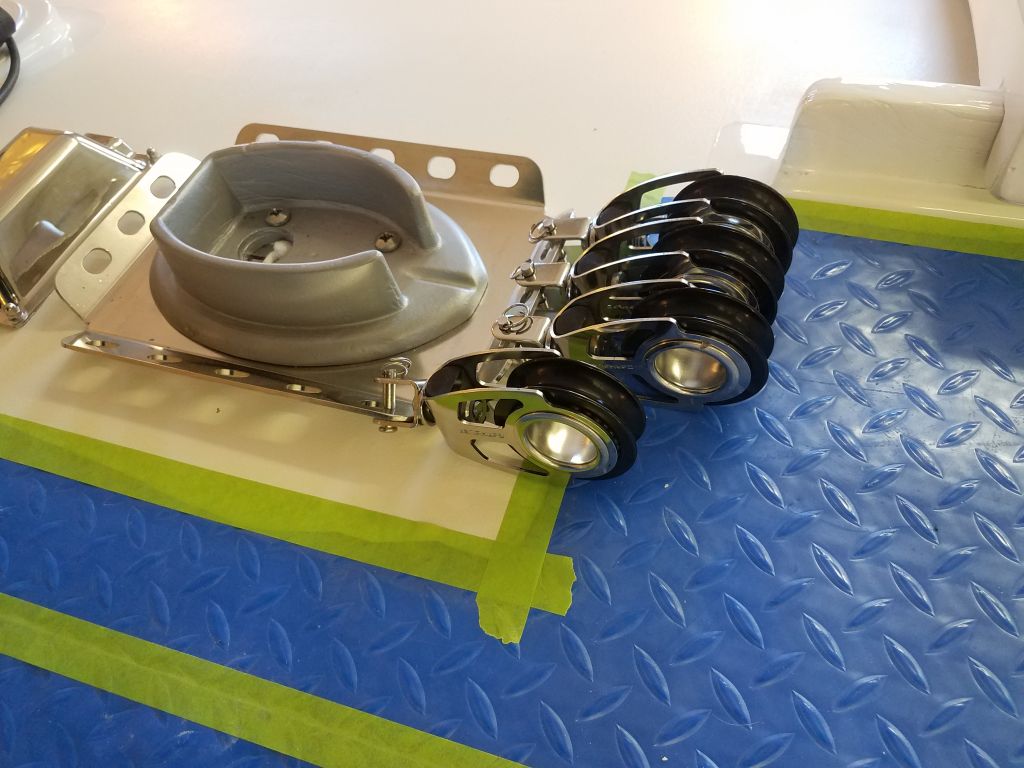
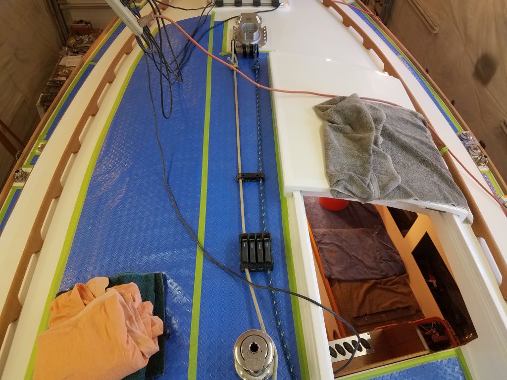
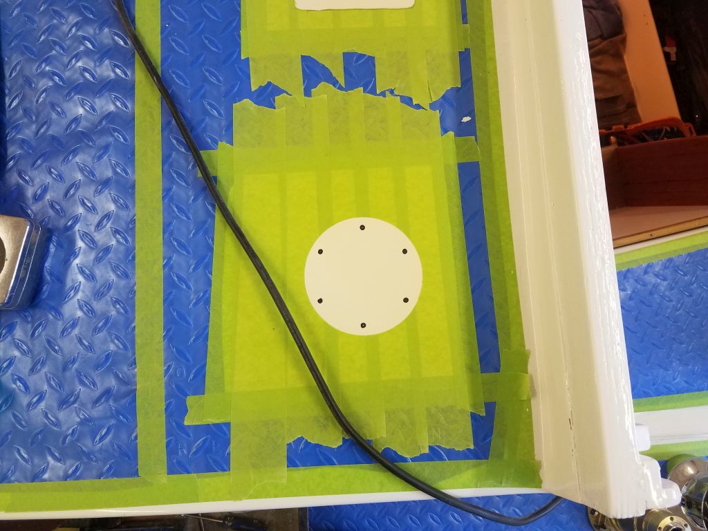
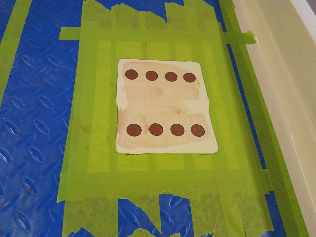
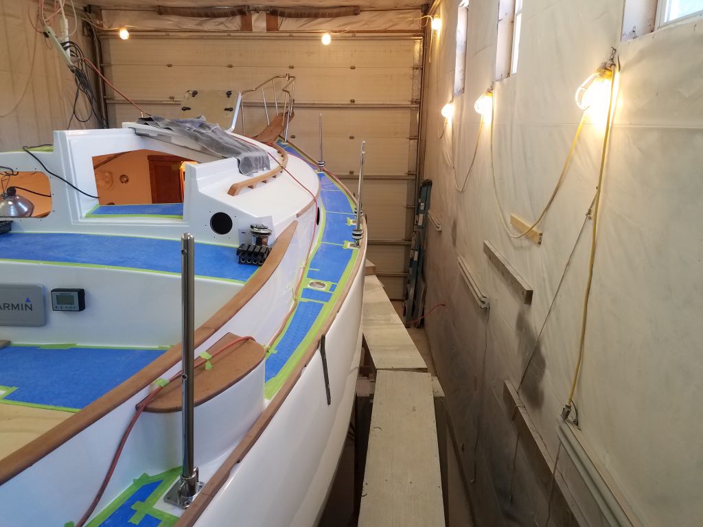
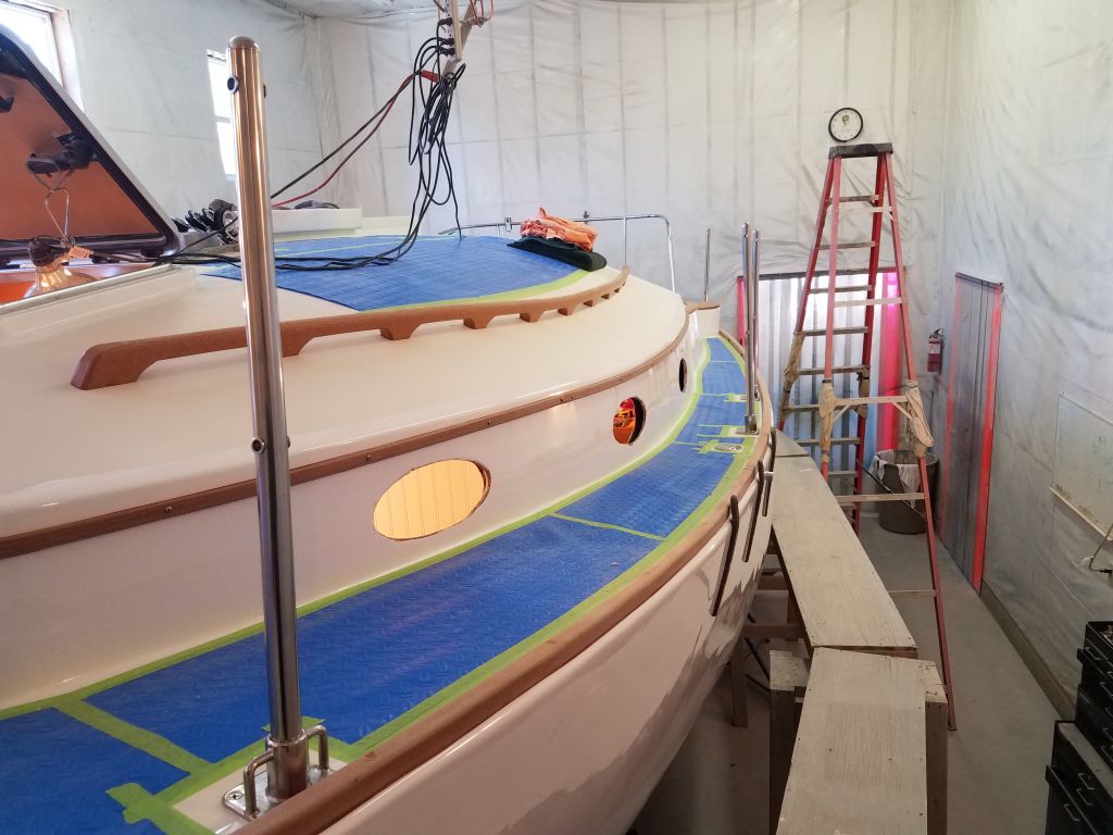
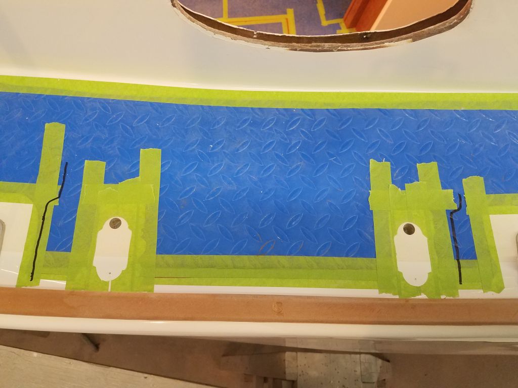
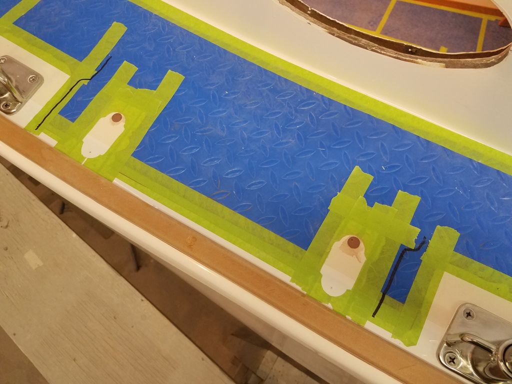
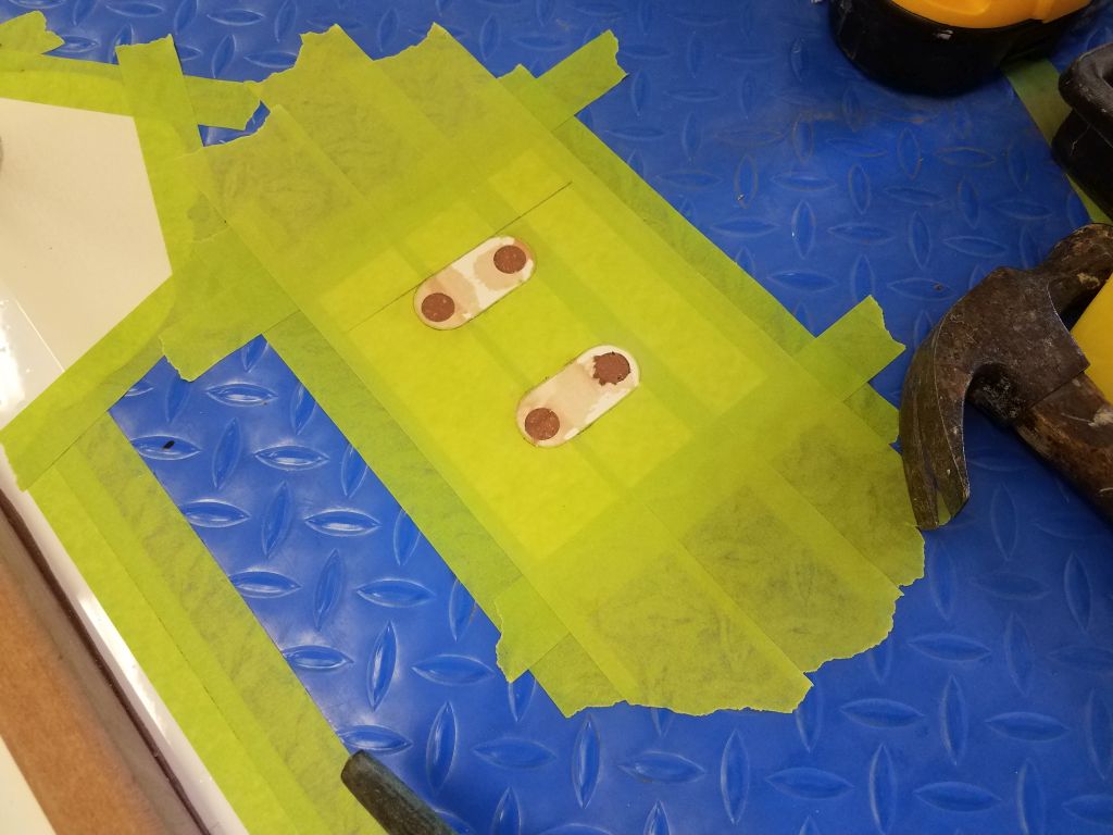
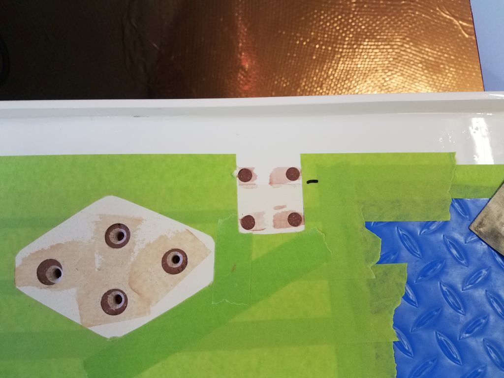
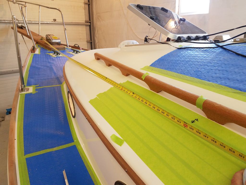
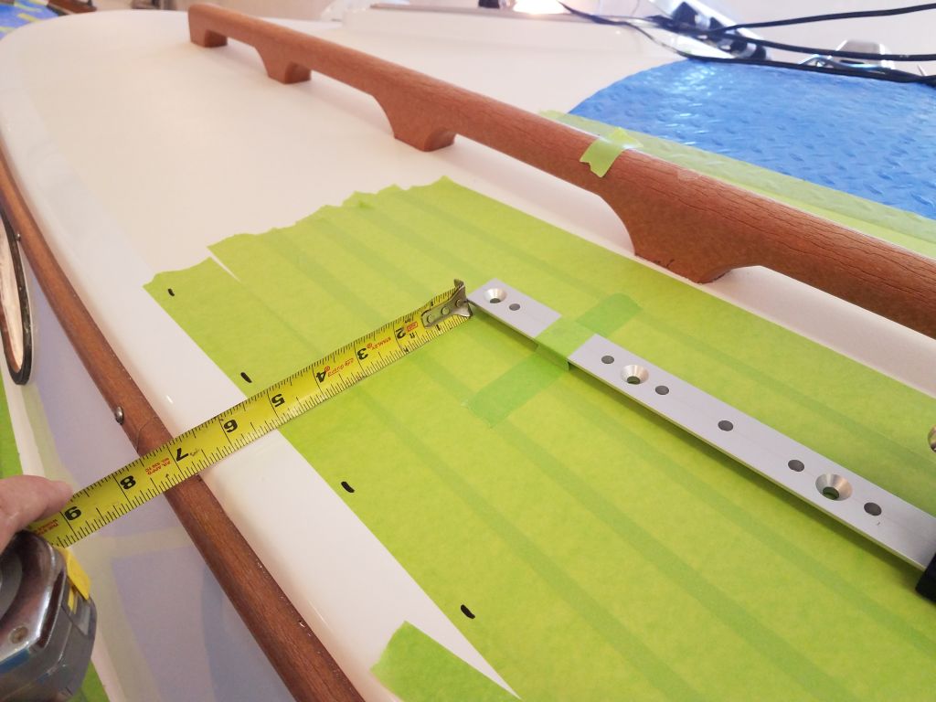
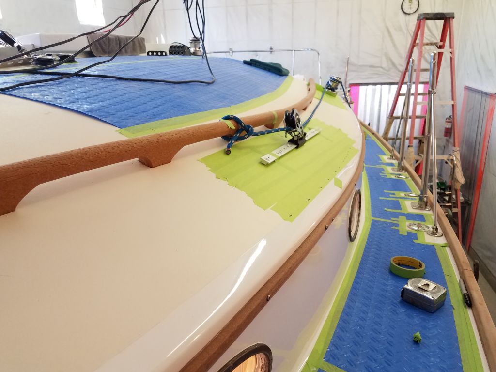
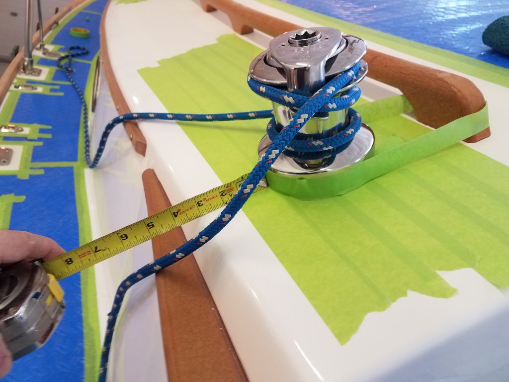
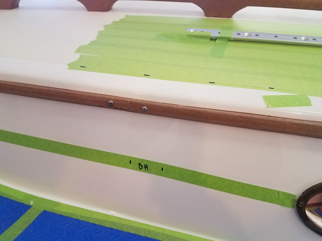
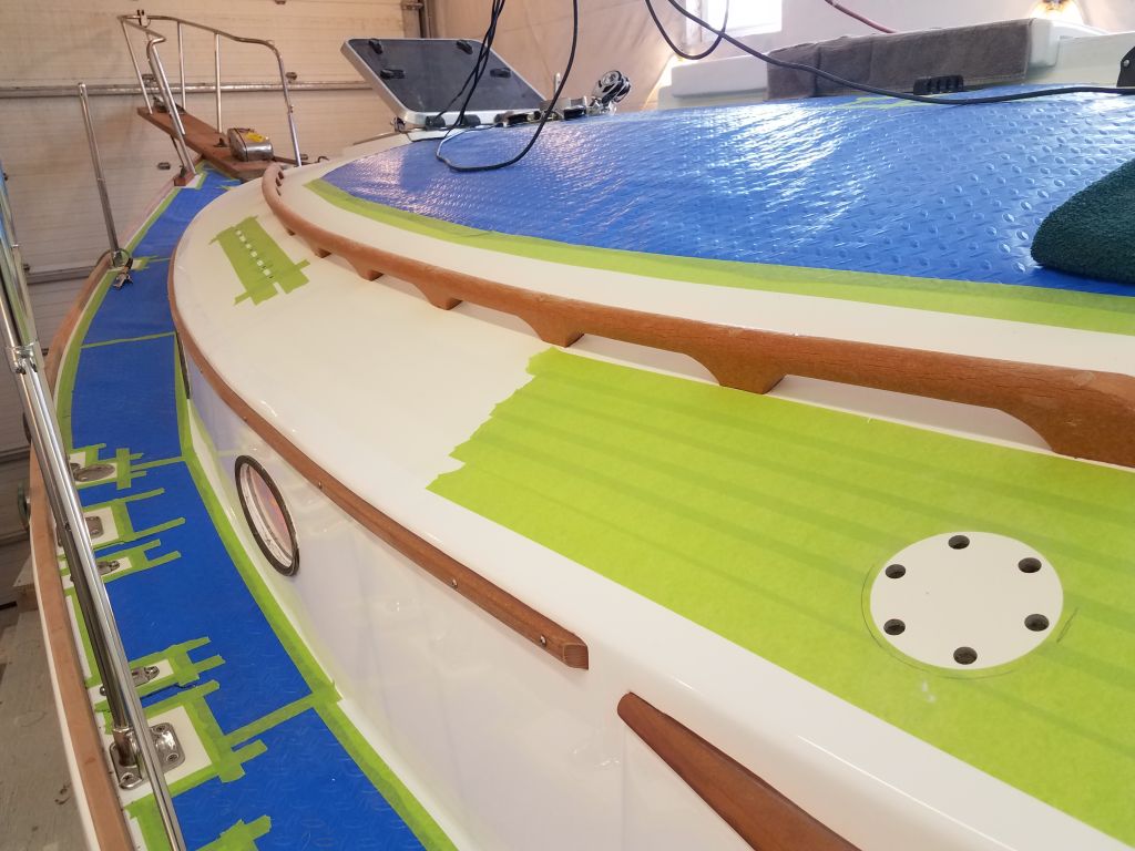
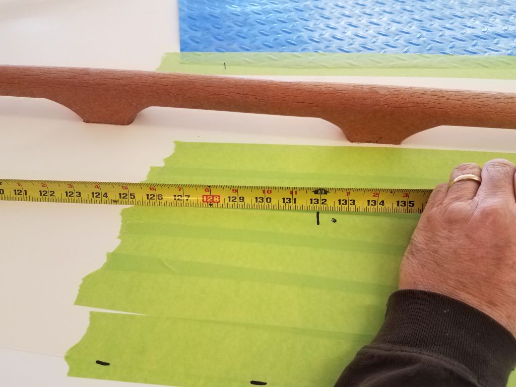
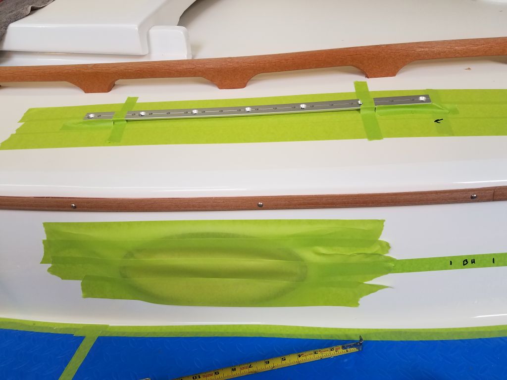
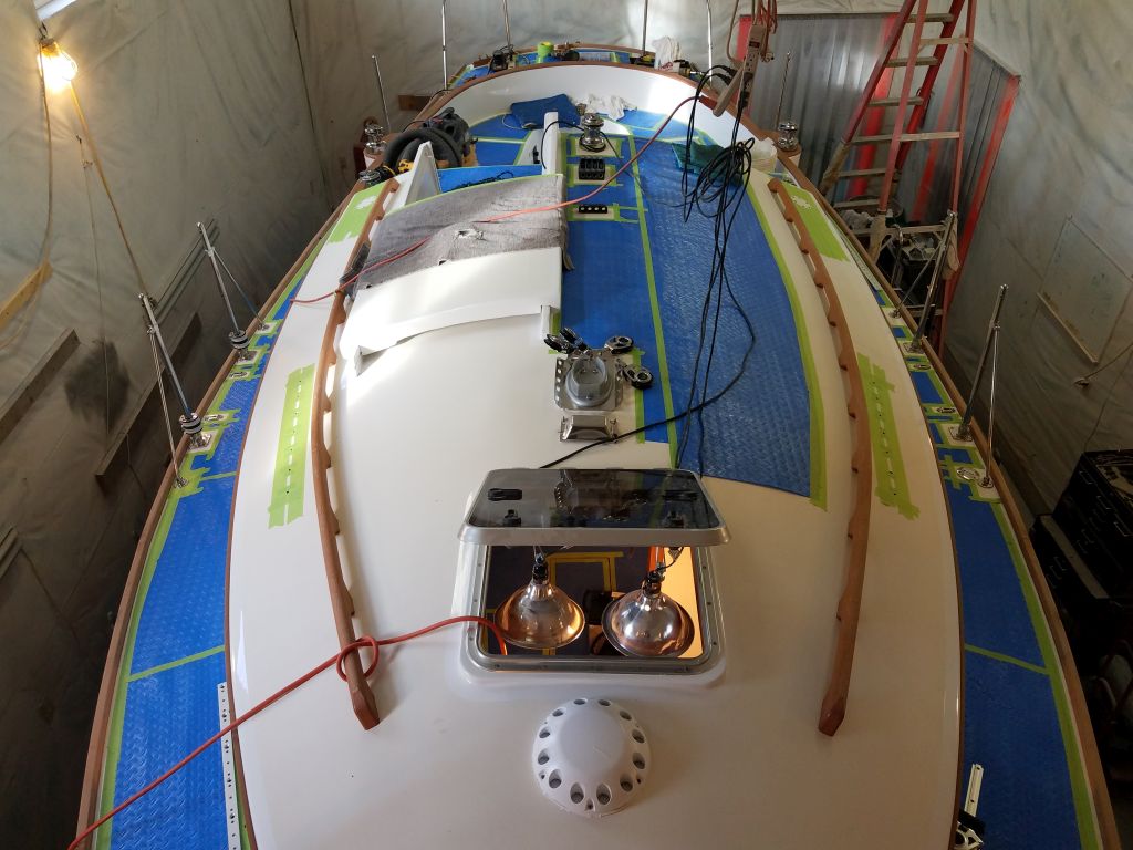
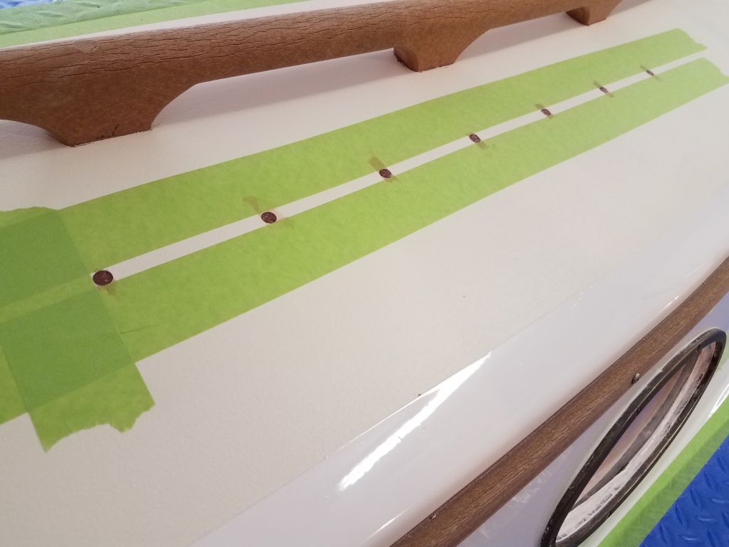
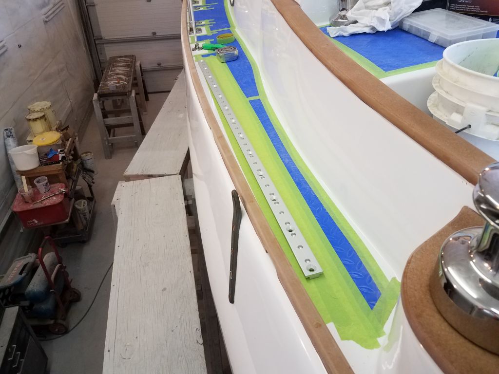
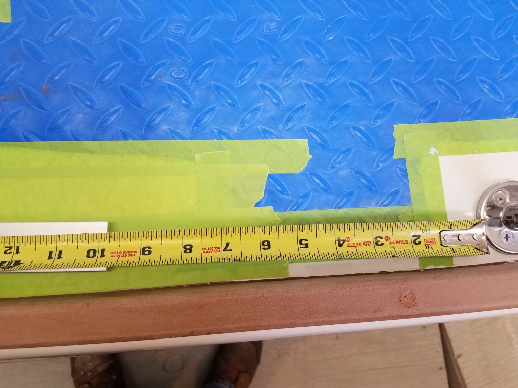
Armed now with information from the sail loft about sheet leads for the new staysail arrangement, I could proceed with the layout for the new staysail sheet tracks and winches, some of the final hardware installations still required.  With a basic measurement of twelve feet aft of the inner forestay attachment point, which equated roughly to a point even with the mast step, I prepared the deck with some masking tape so I lay out the new 2′ tracks I had for the staysail sheets. I started on the port side since it was there.

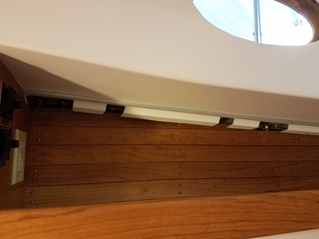
The design of the coachroof required that the staysail sheet tracks be somewhere outboard of the handrails, which fit in fine with the requirements of the sail, but I had to be sure the sheet could lead fairly from the chosen point adjacent to the mast (with the center of the track at the 12′ sweet spot) aft to the winch locations, which had to be near the outboard corners of the cabin trunk on each side.

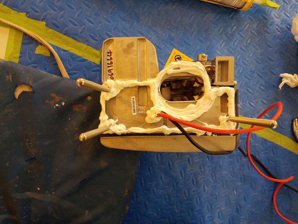
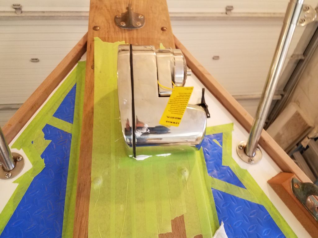
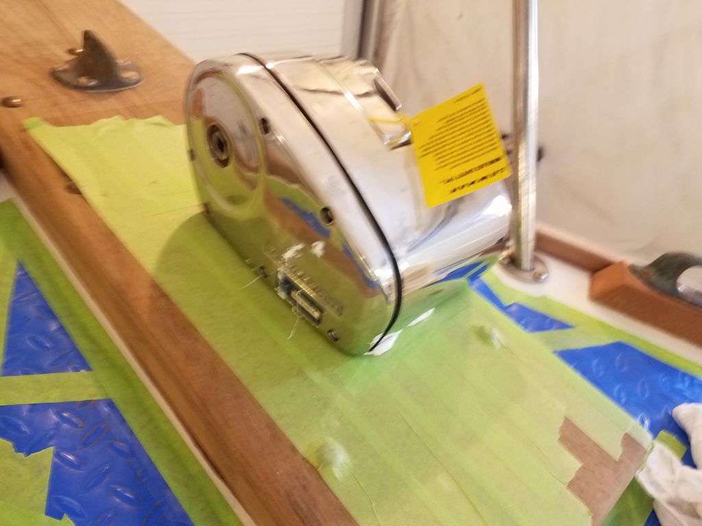
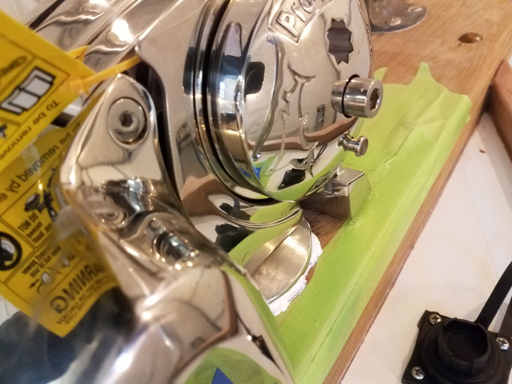
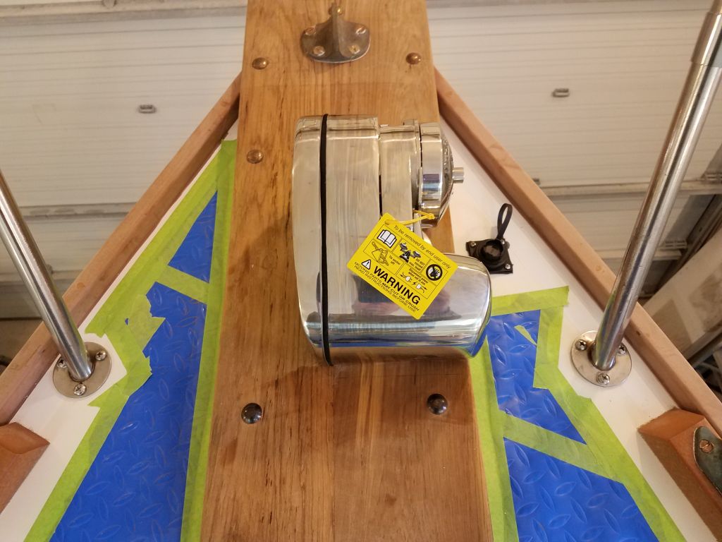
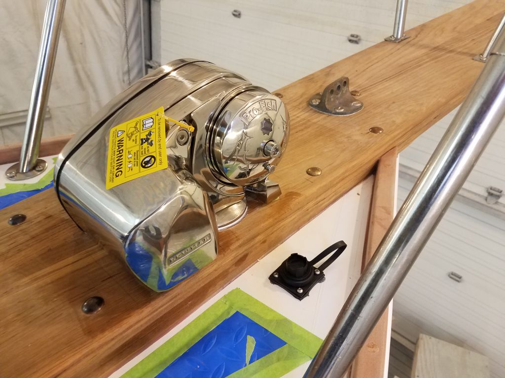
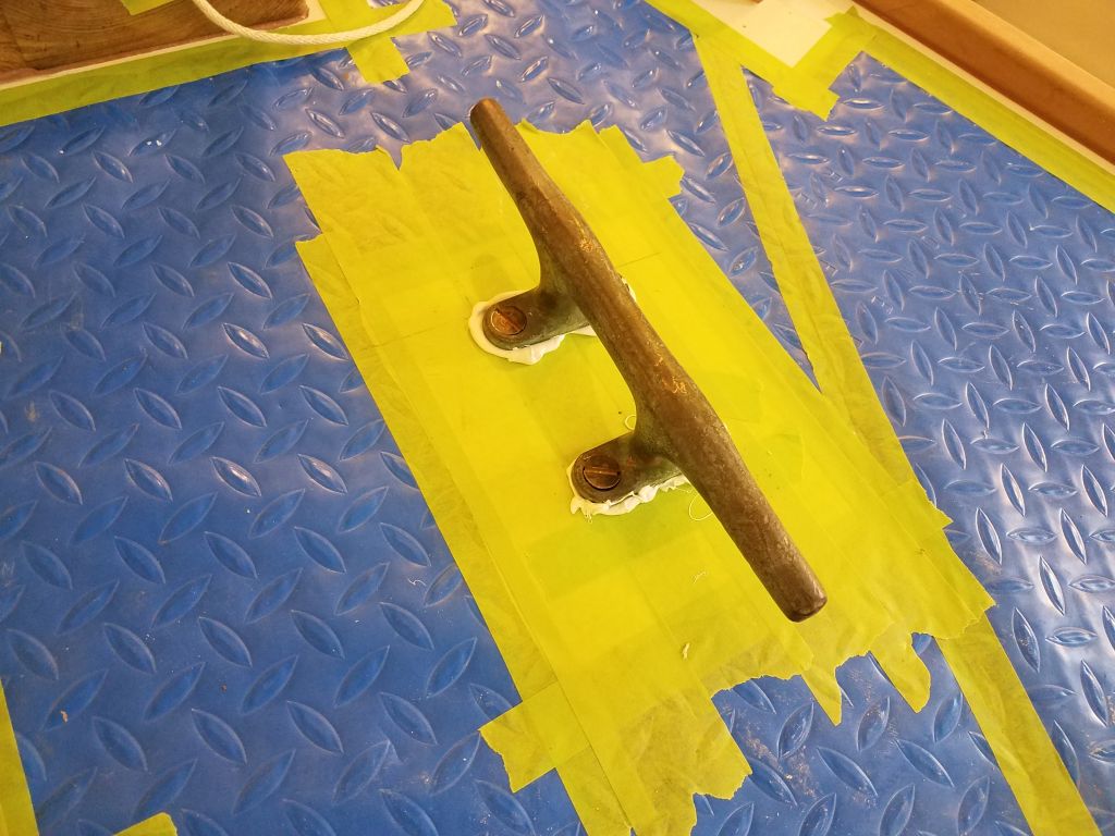
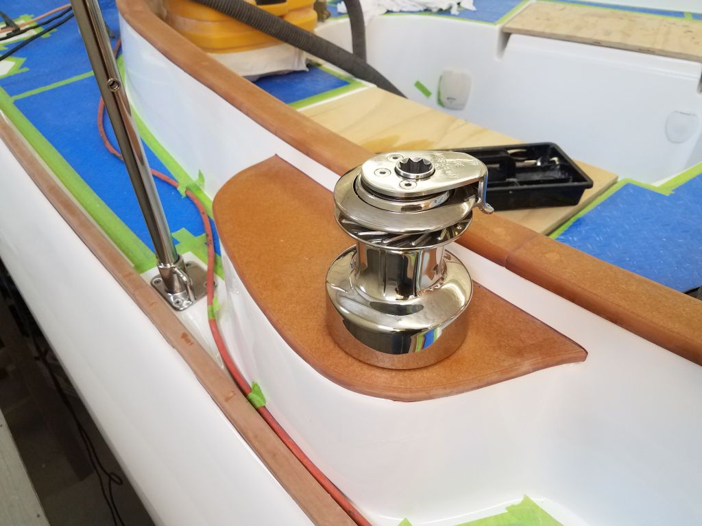
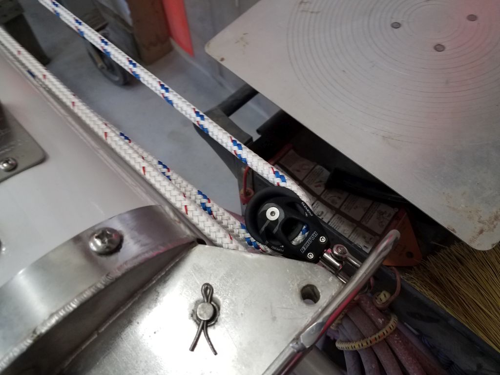
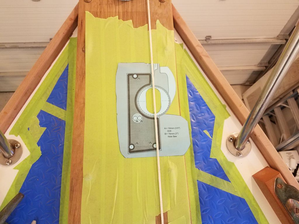
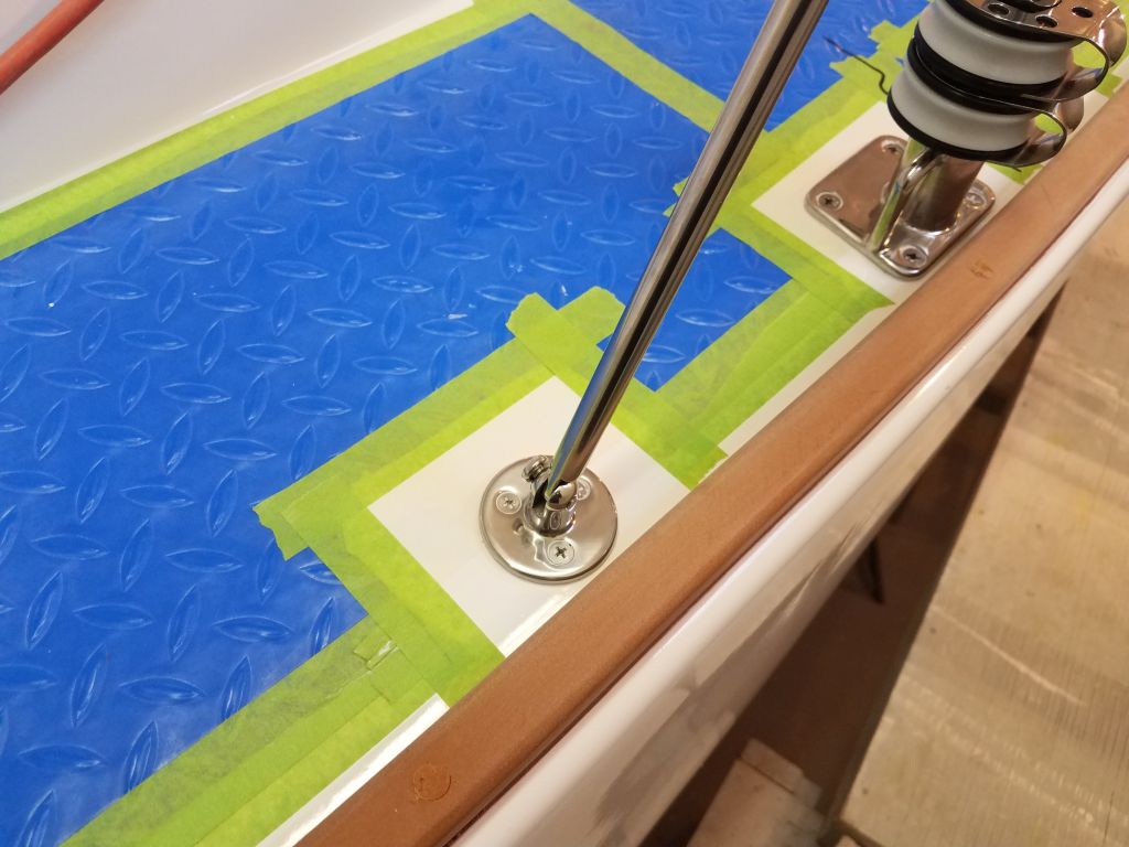
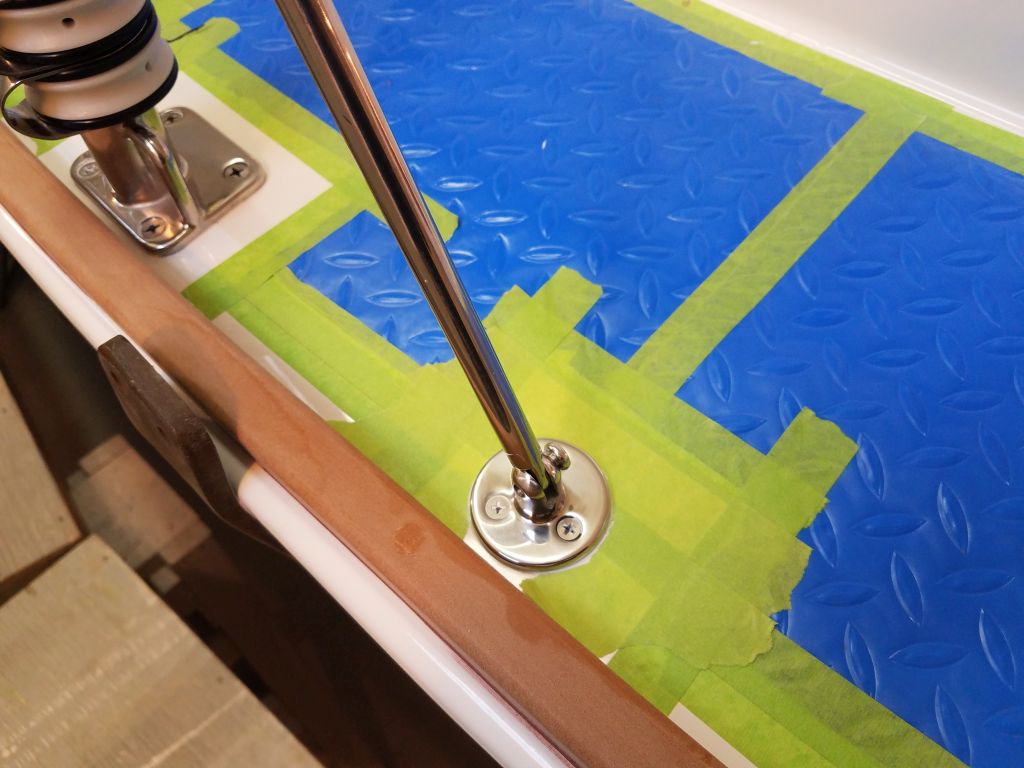
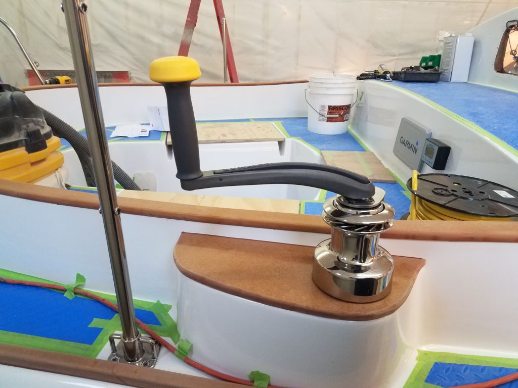
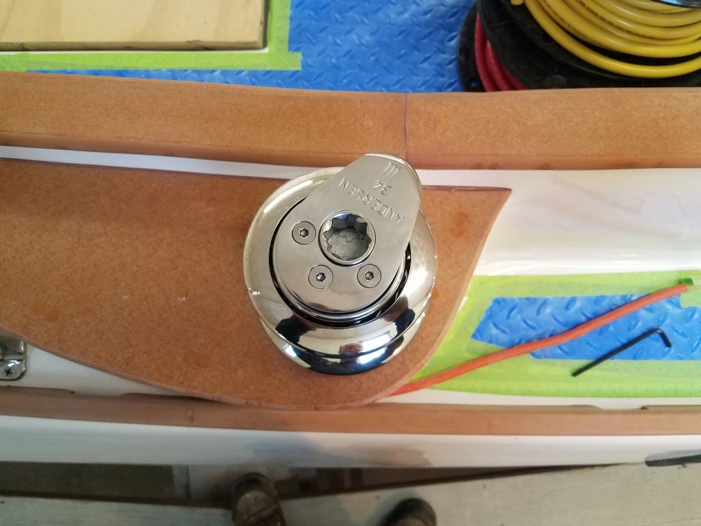
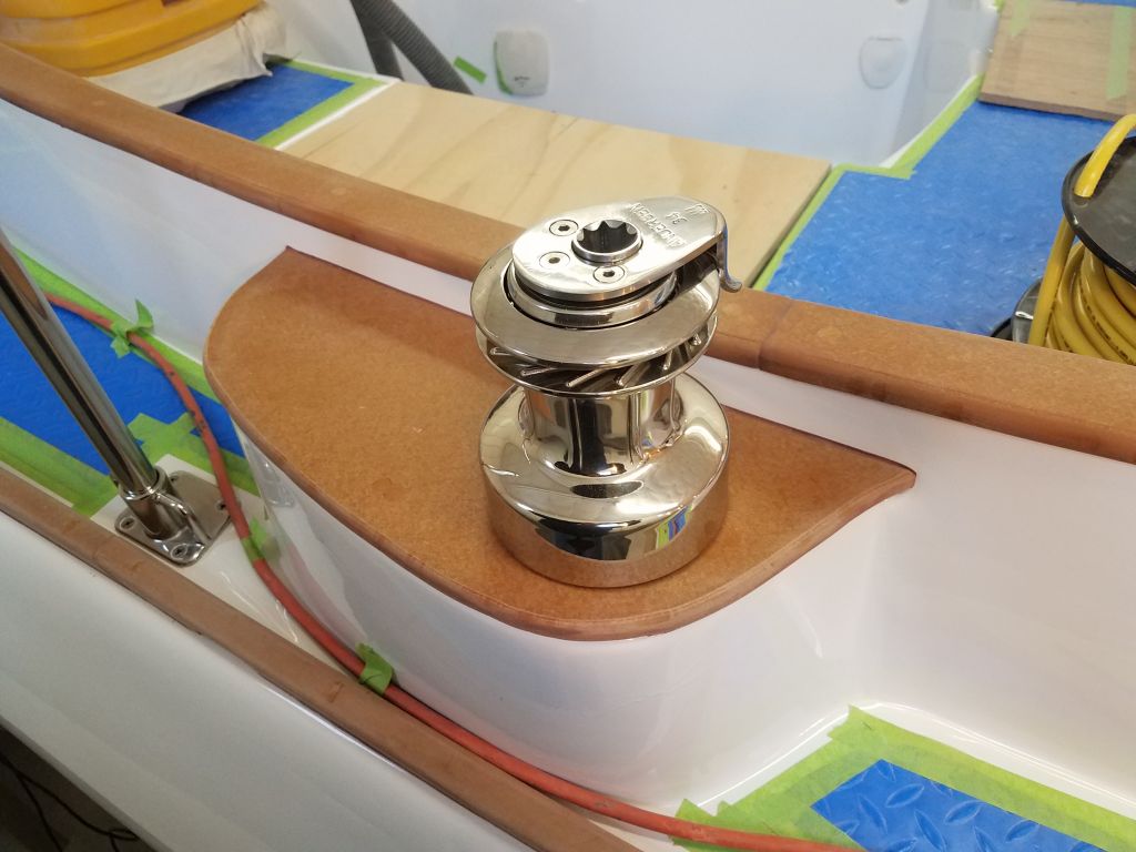
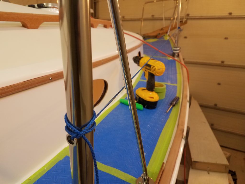
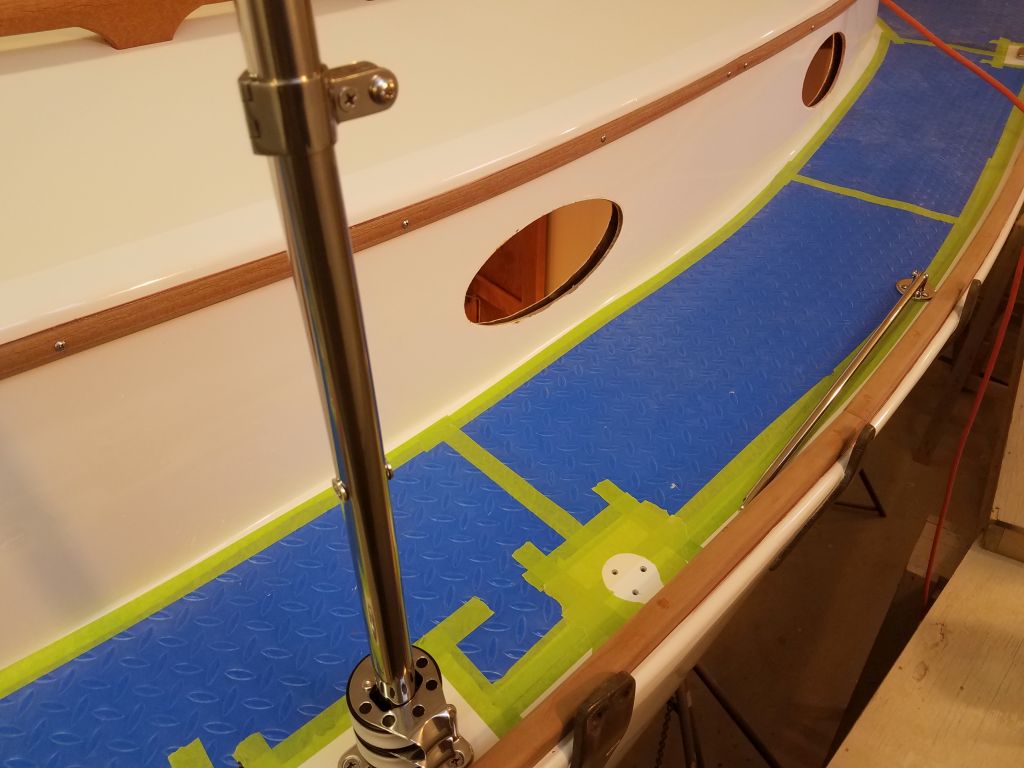
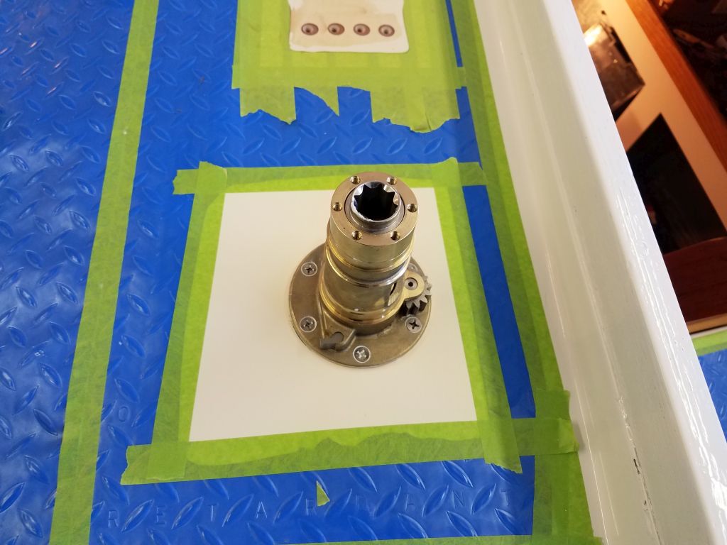
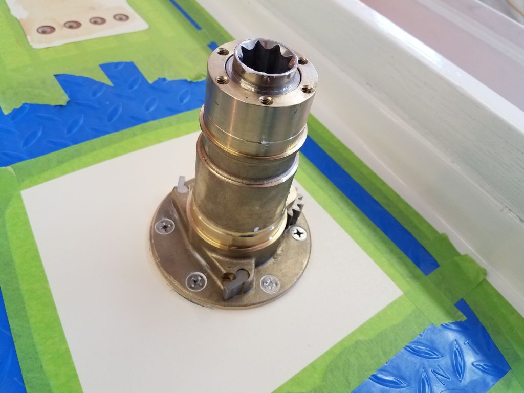
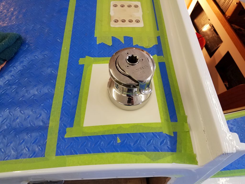
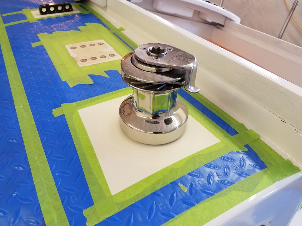
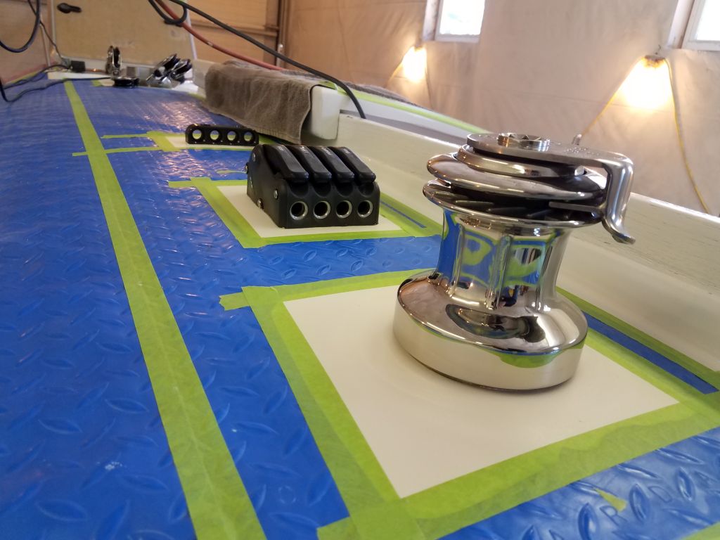
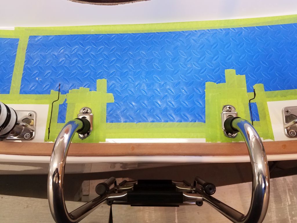
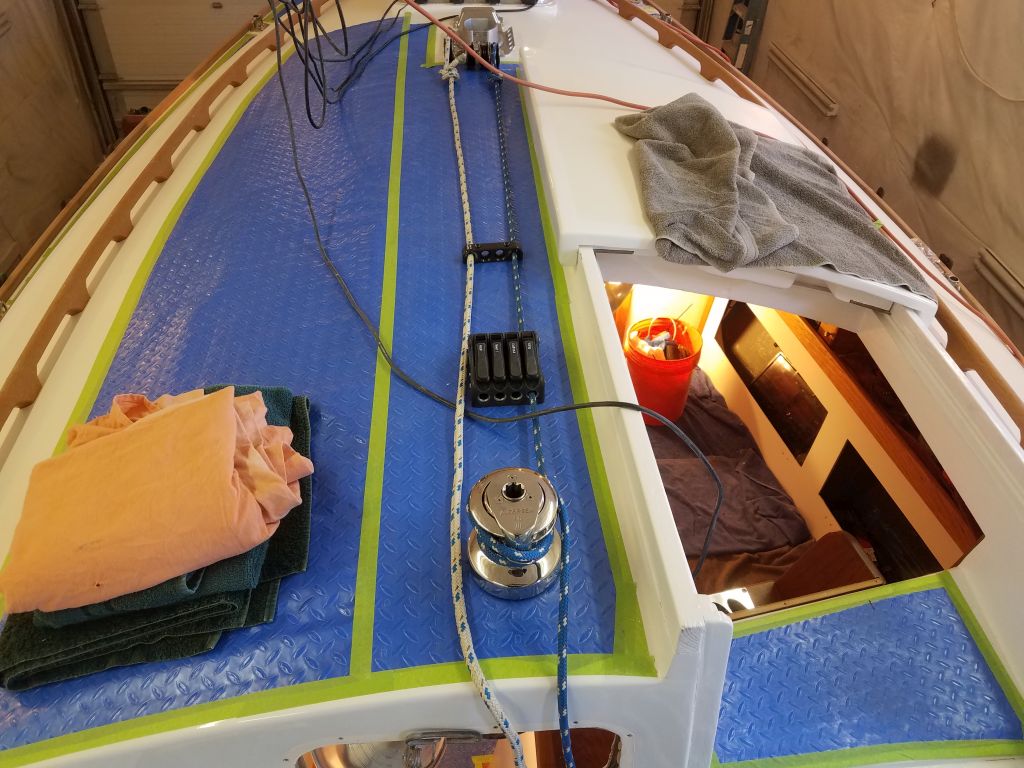
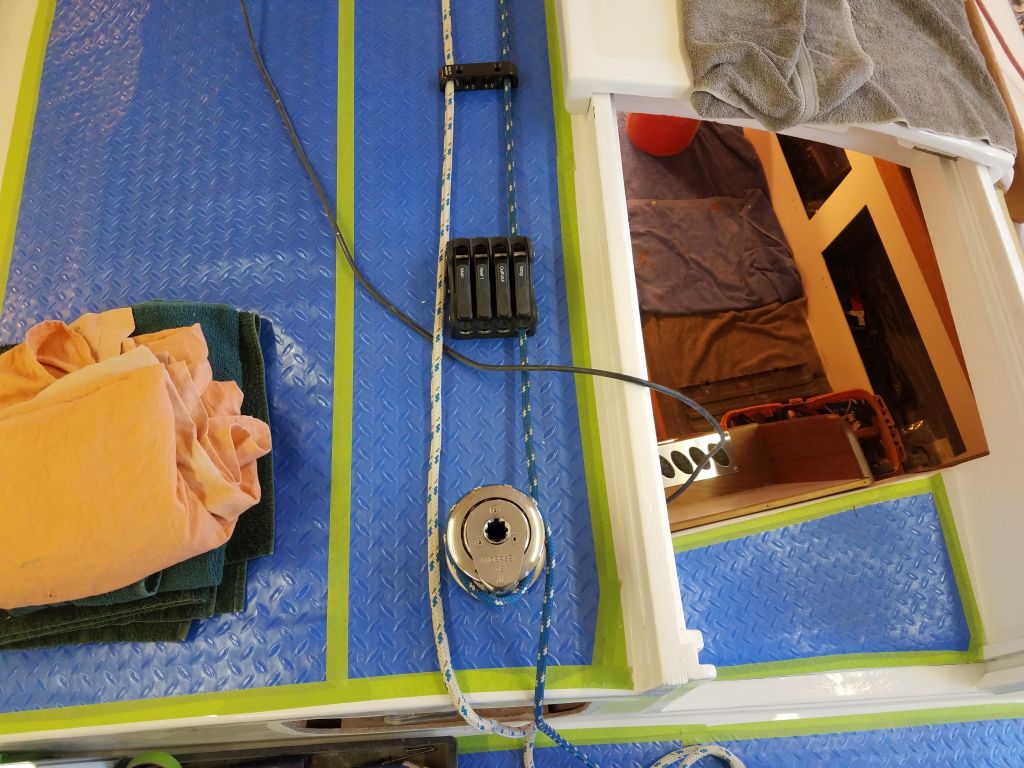
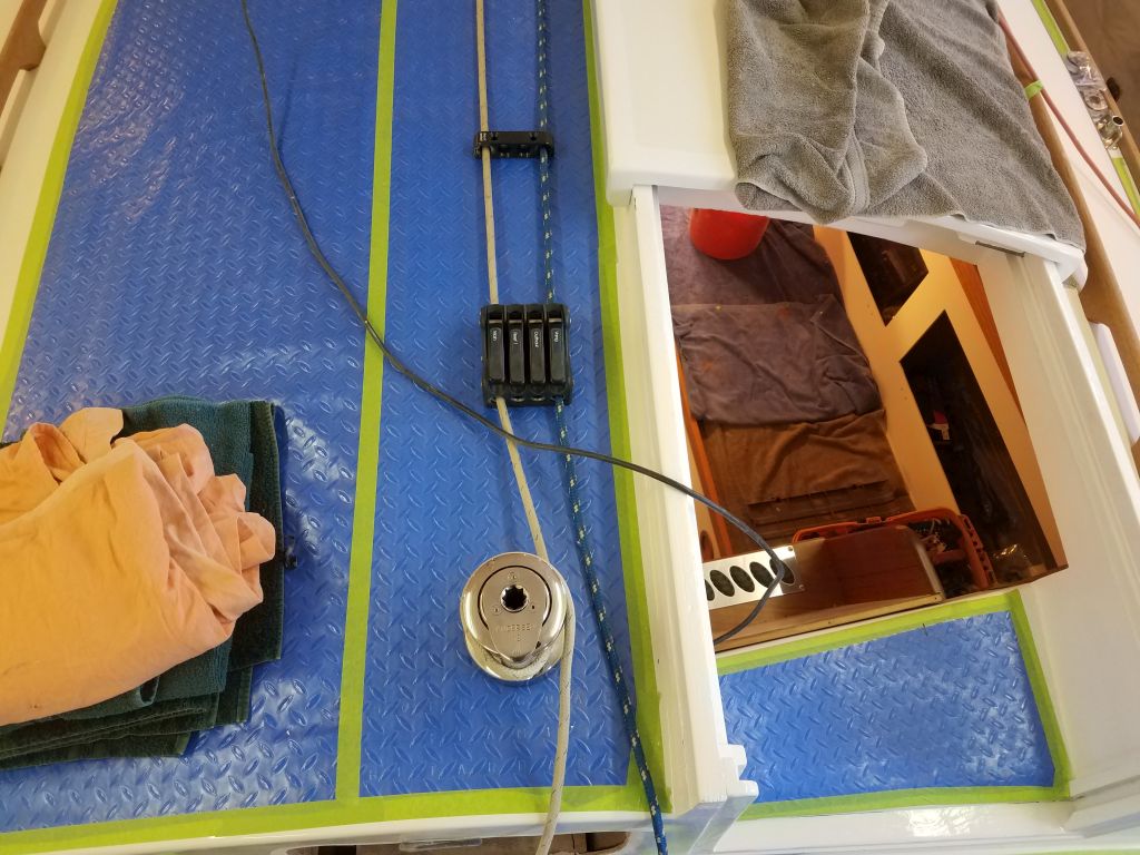
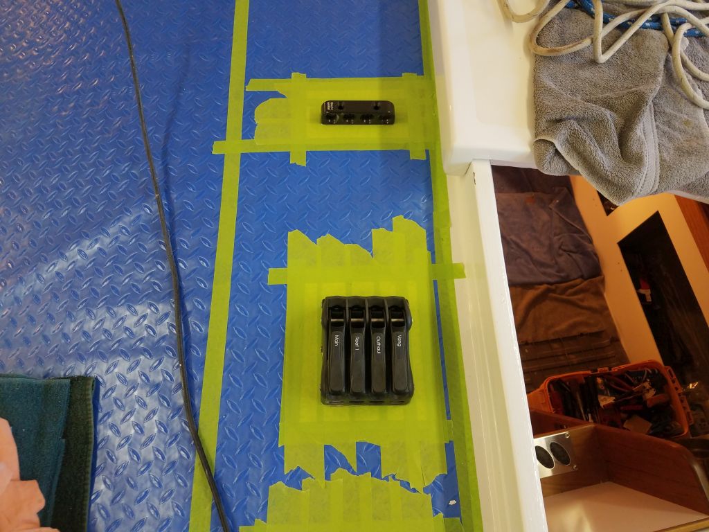
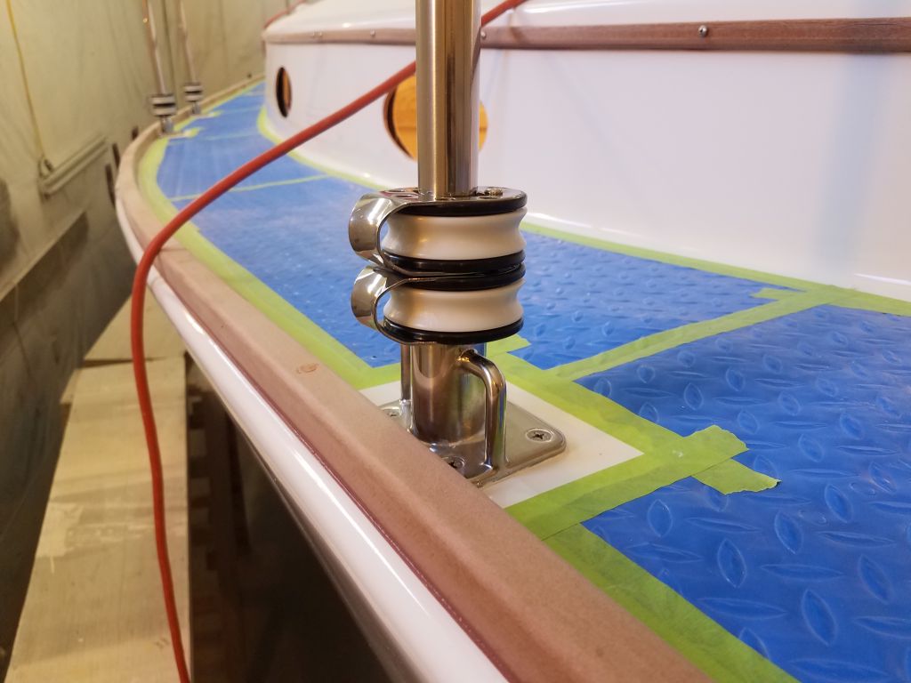
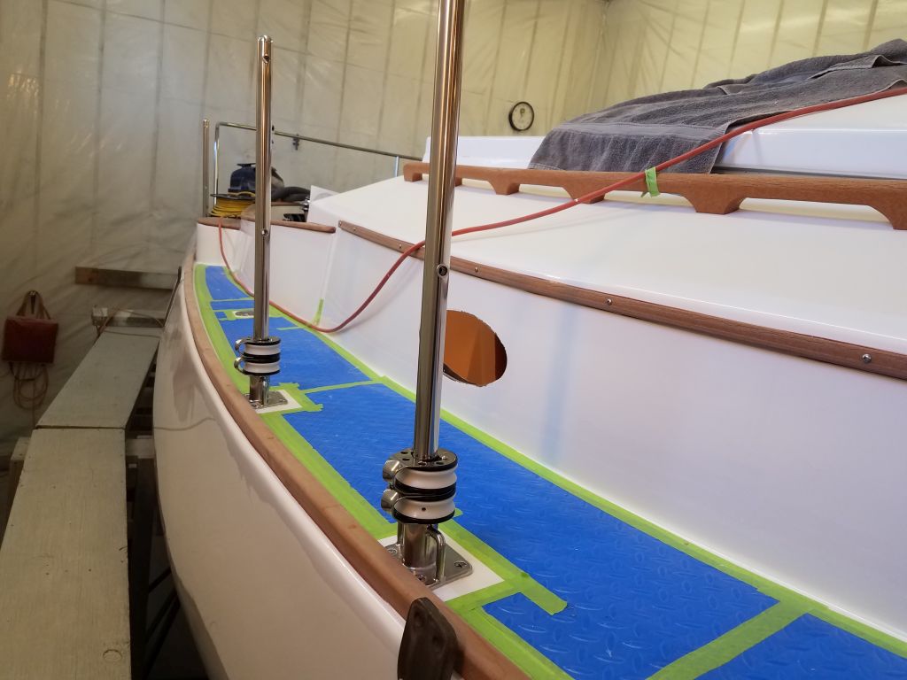
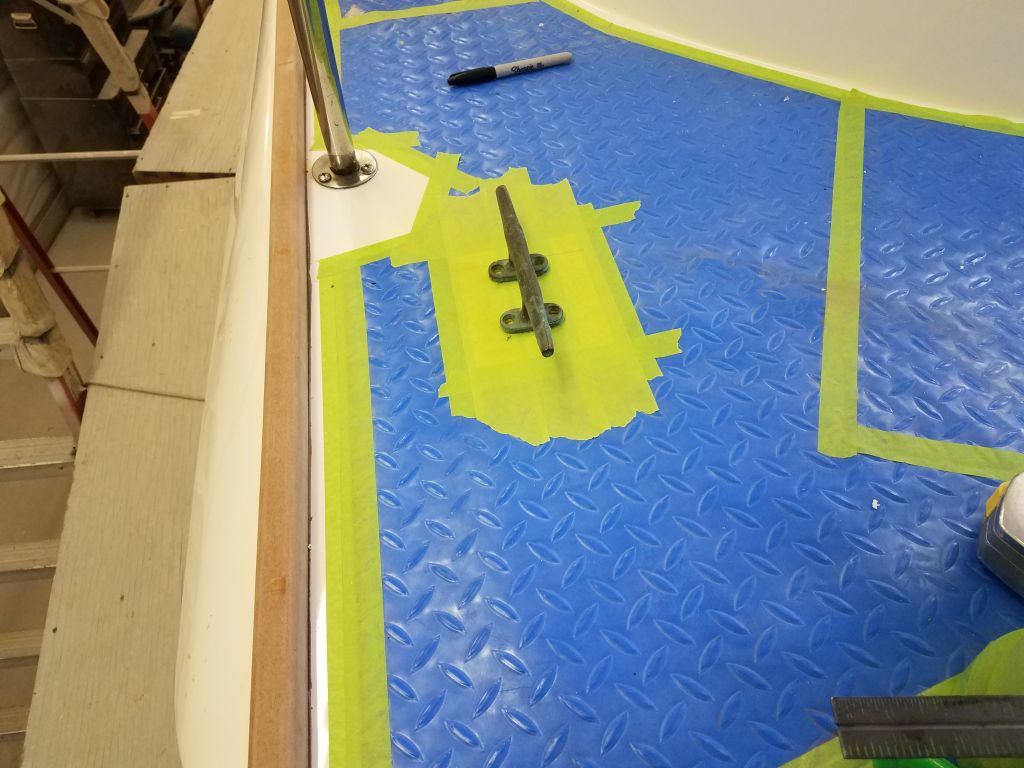
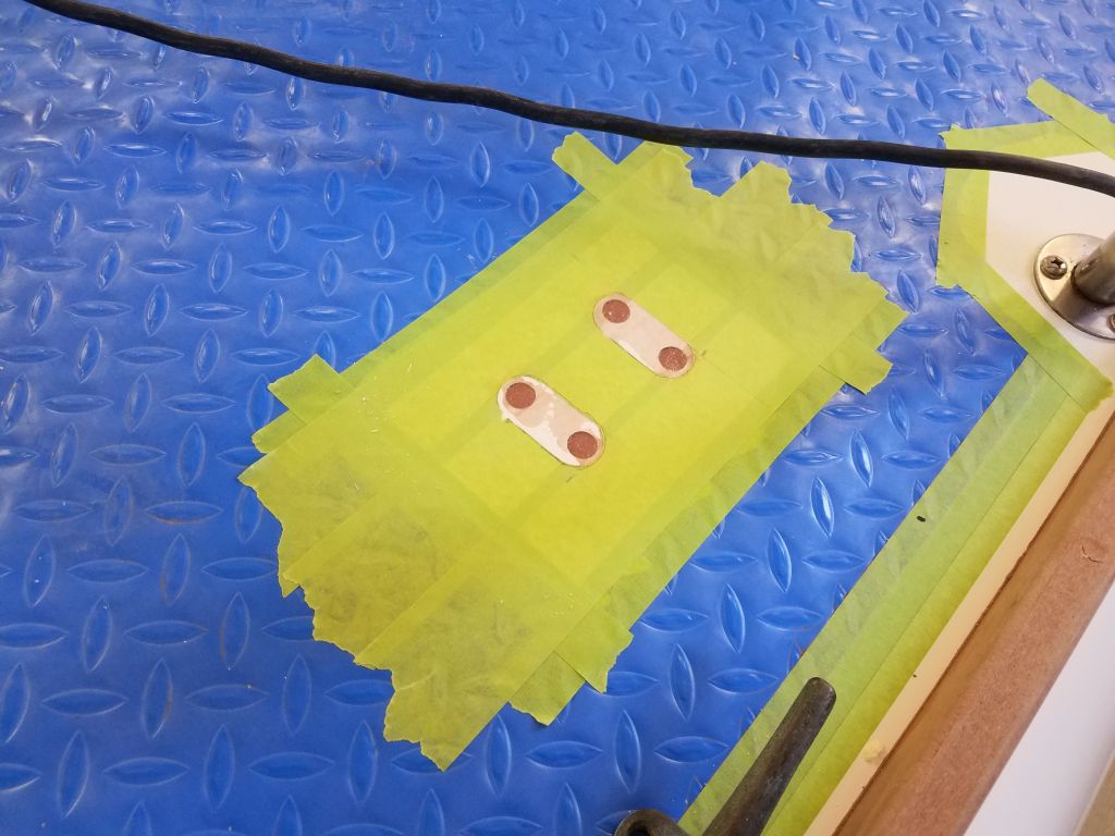
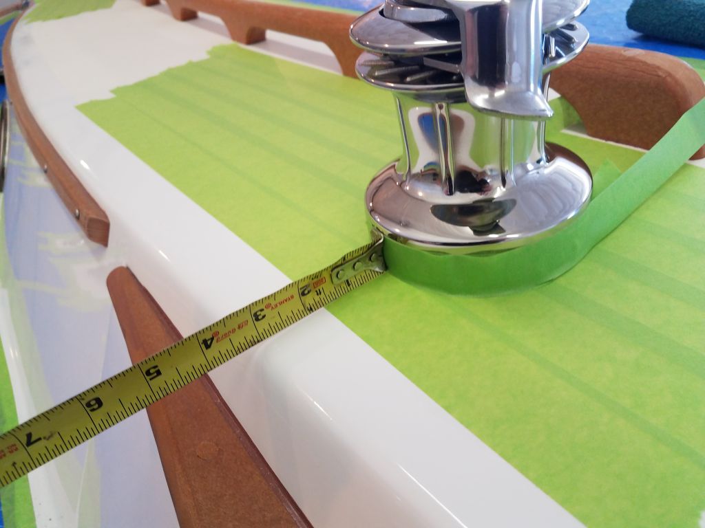
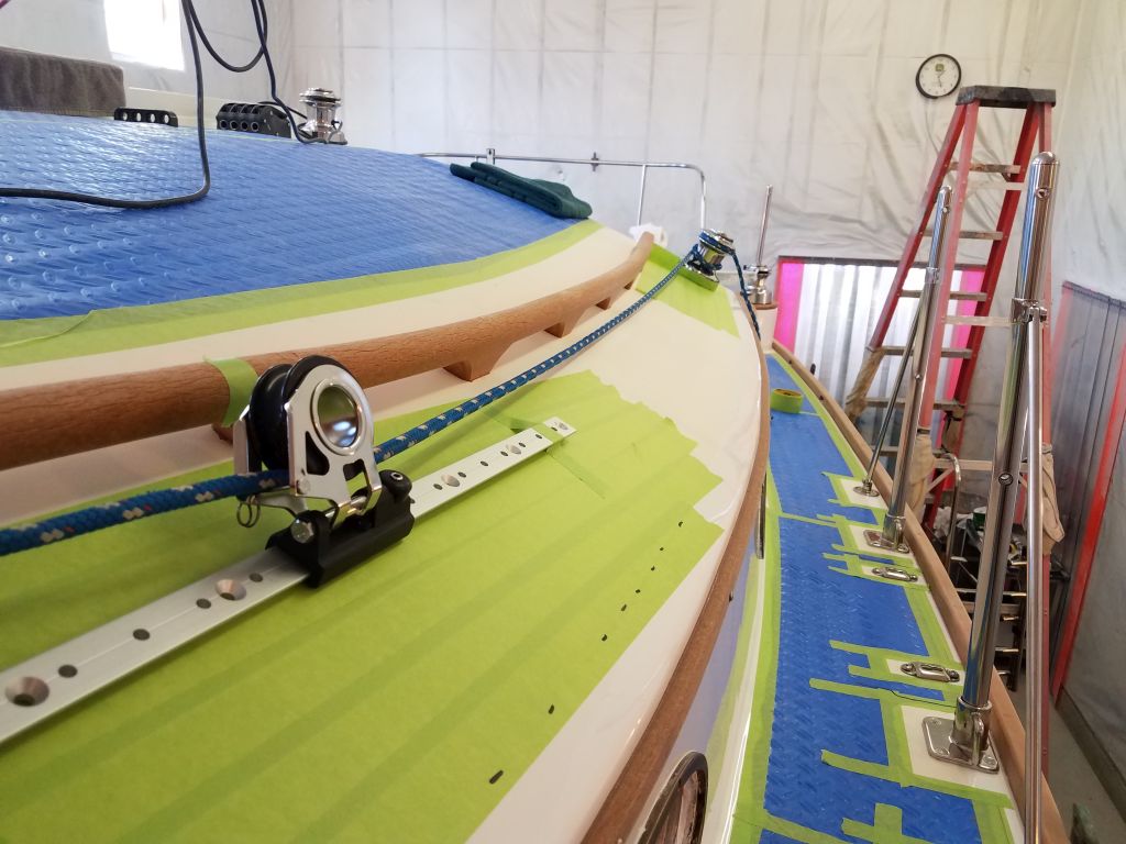
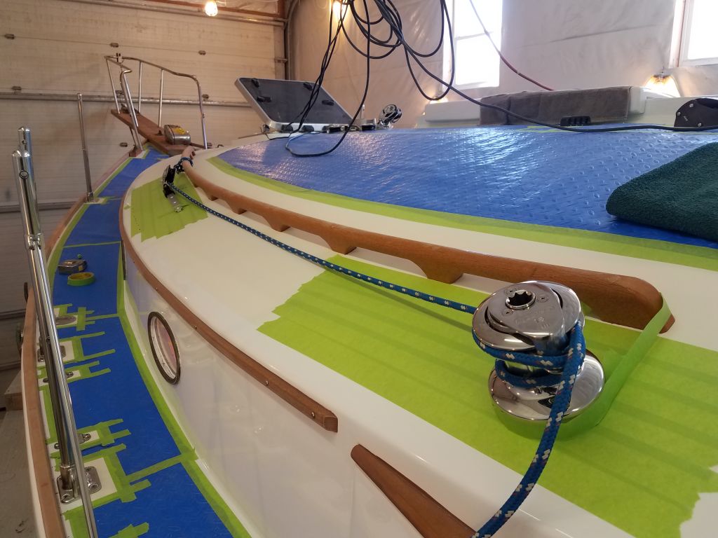
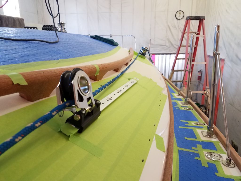
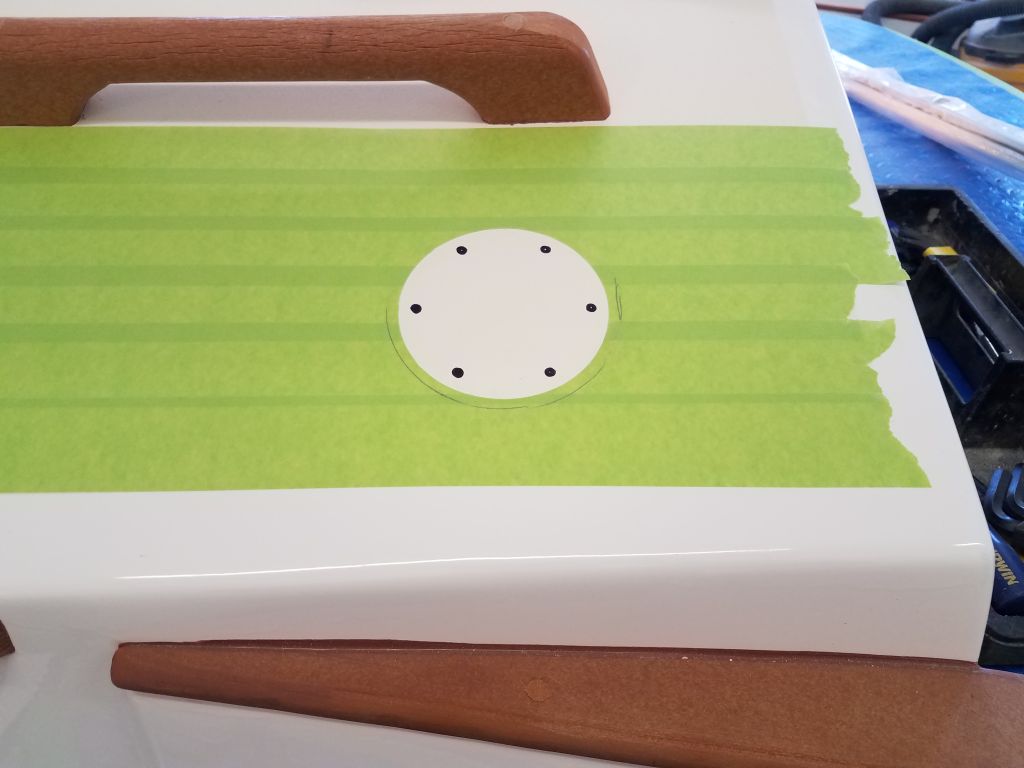
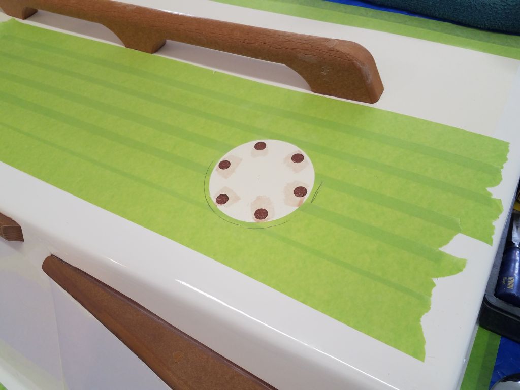
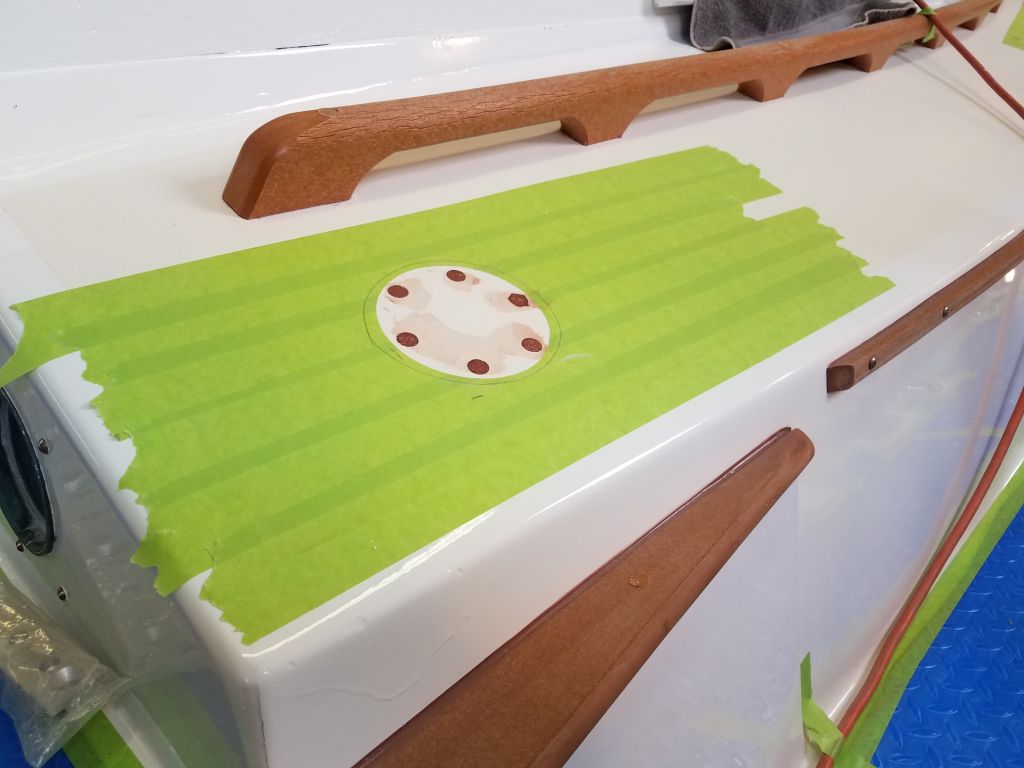
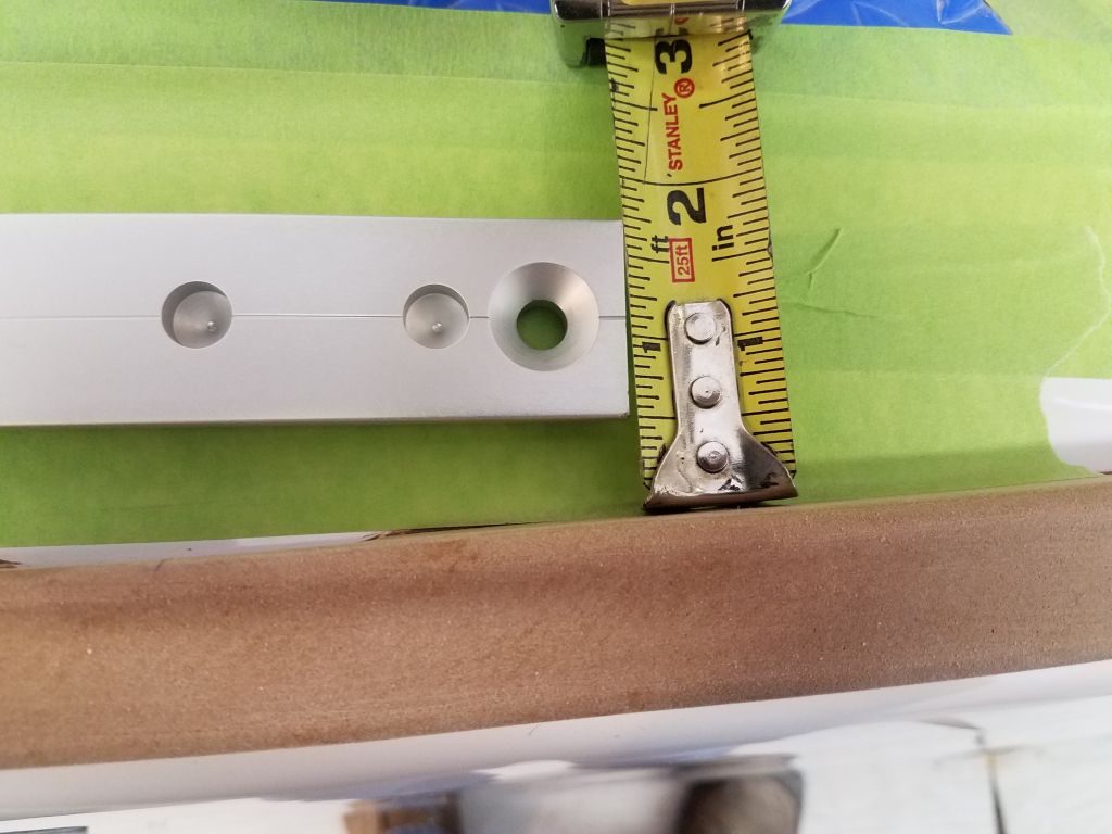
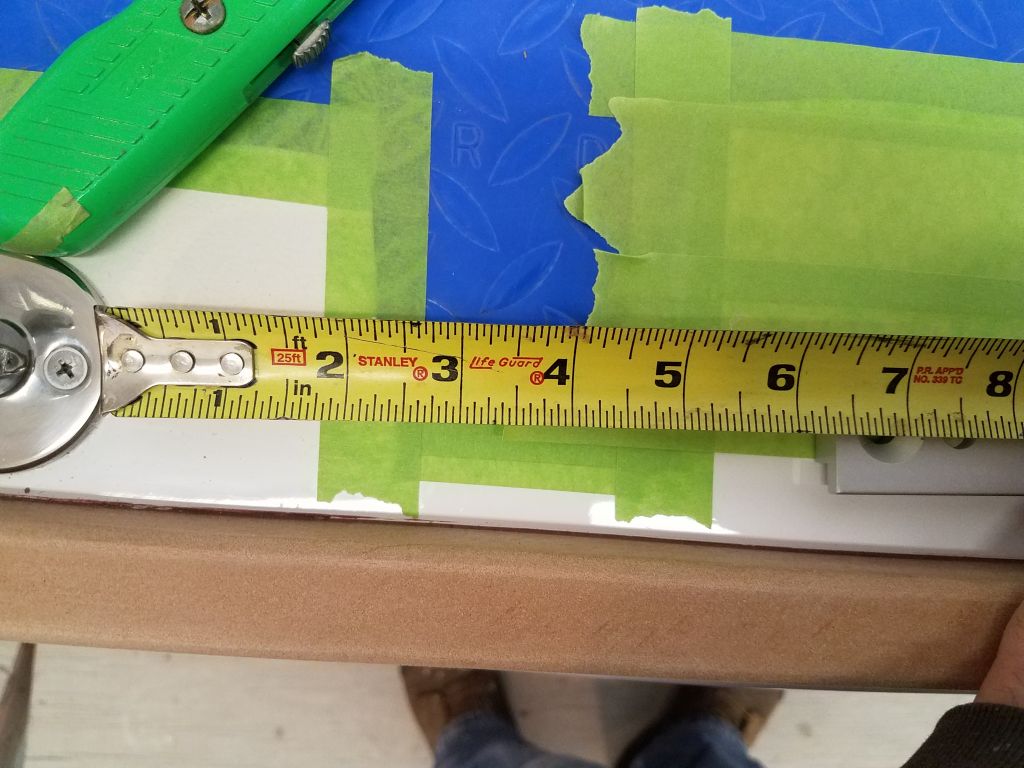
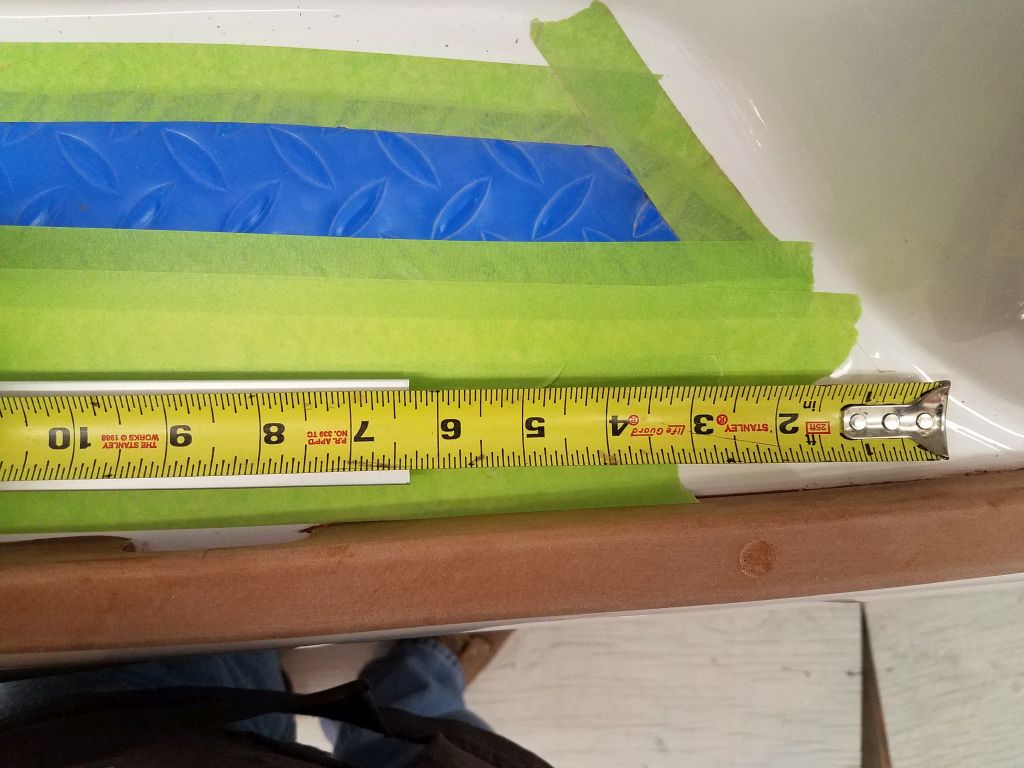
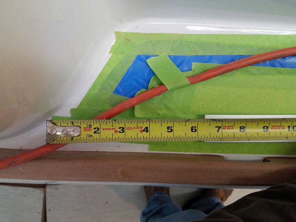
So as part of the initial layout, I placed the winch where I thought it should be, roughly centered between the handrail and the edge of the cabin trunk (3″), and in line with the aft edge of the handrail (6″).  I held the winch in place against the slope of the coachroof with some masking tape.  Then, more or less visually, I determined roughly where I thought the track should go, which I wanted as far inboard as possible while retaining clearance from the handrails for the lead car, as well as a fair lead aft to the winch.  This ended up being 5″ inboard from the edge of the nonskid.

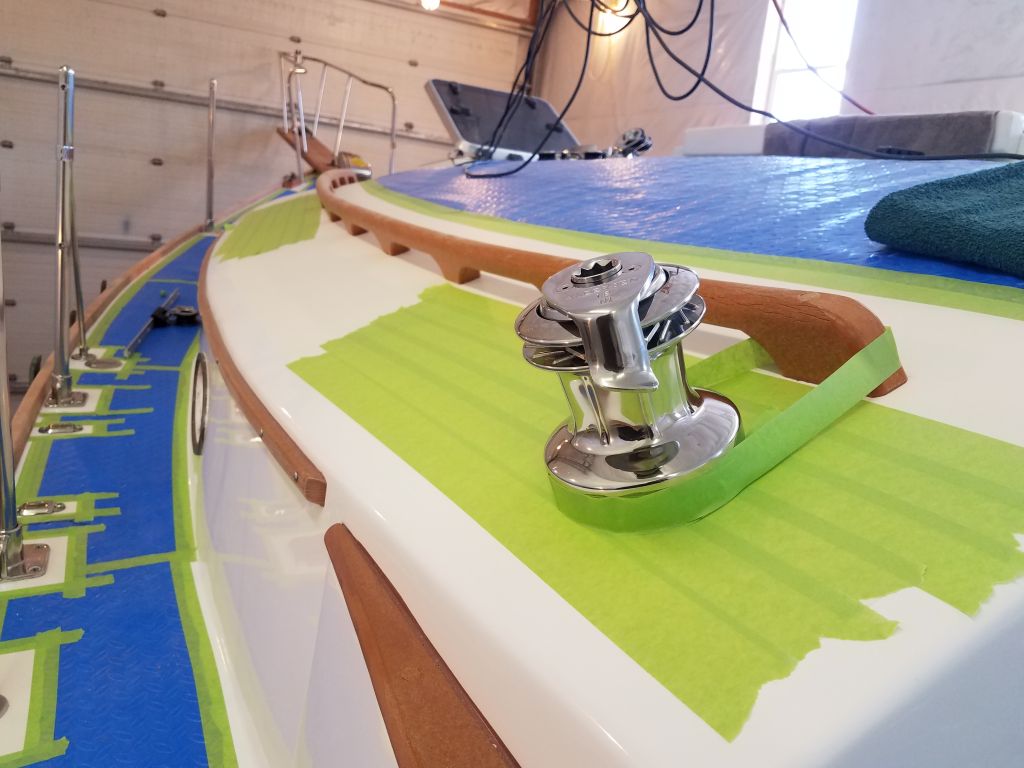
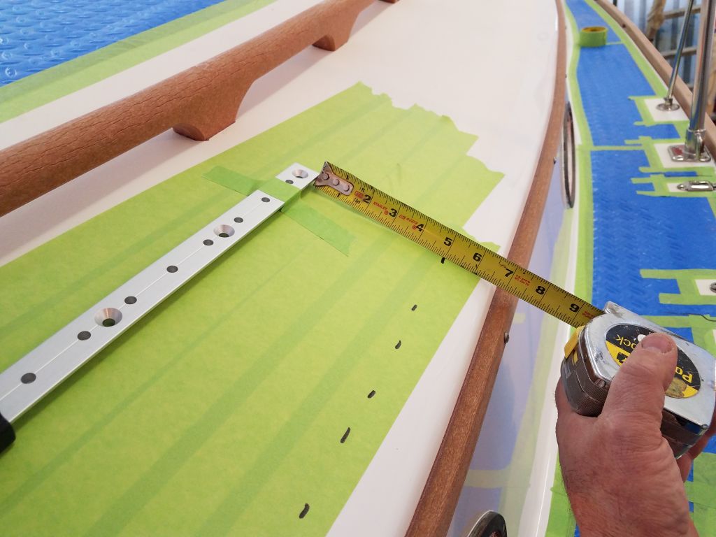
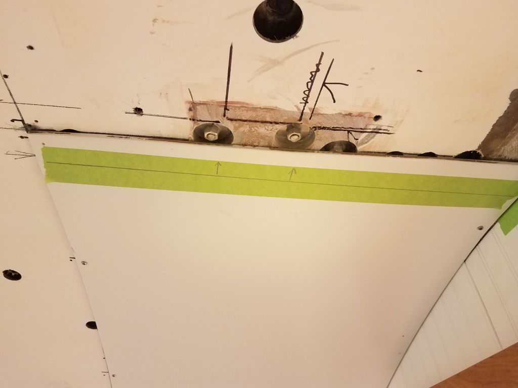
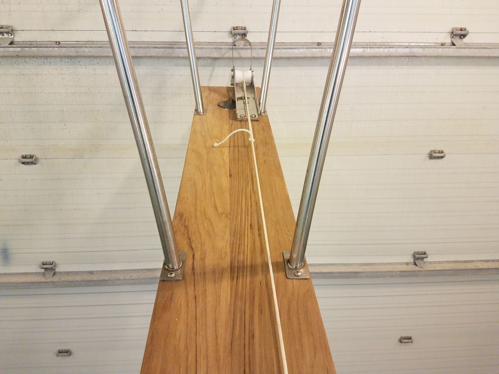
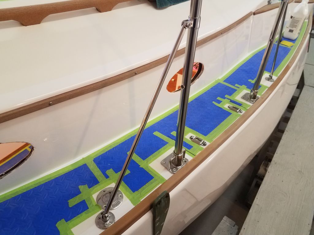
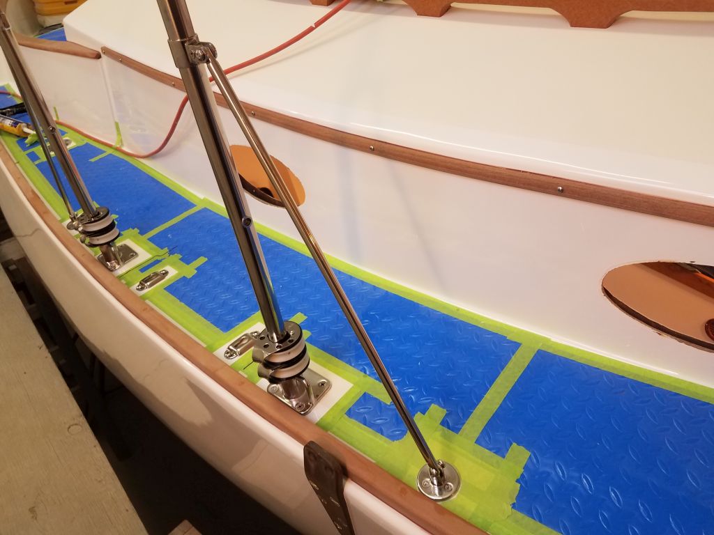
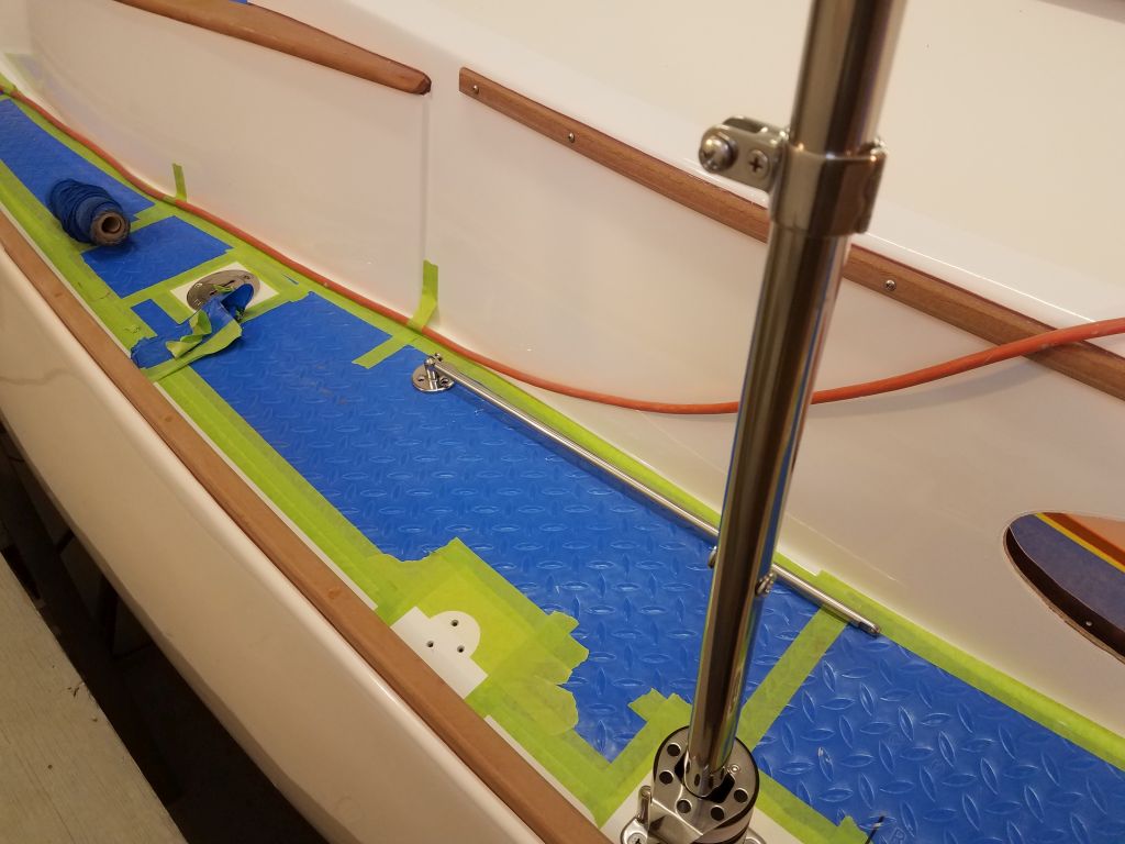
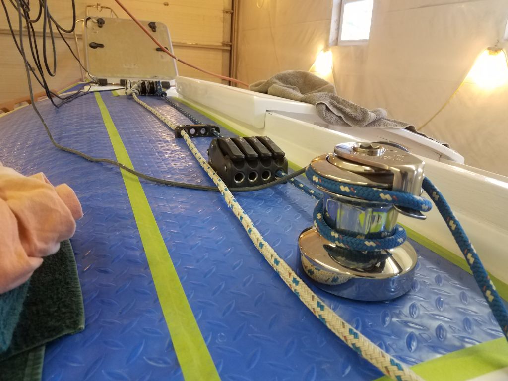
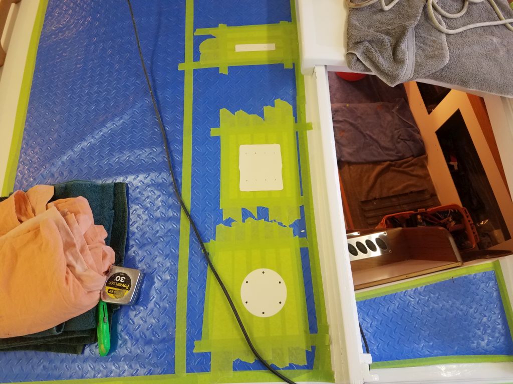
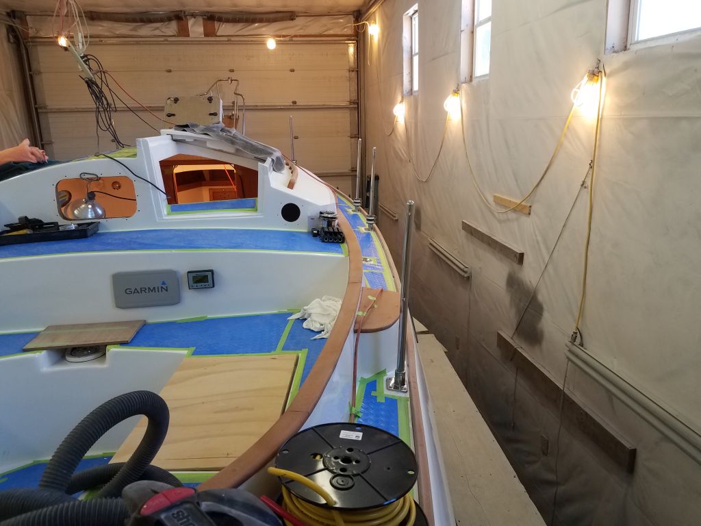
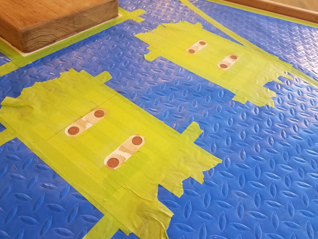
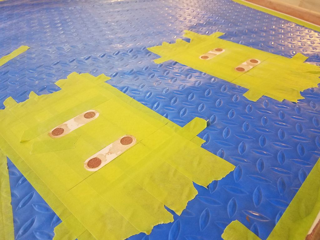
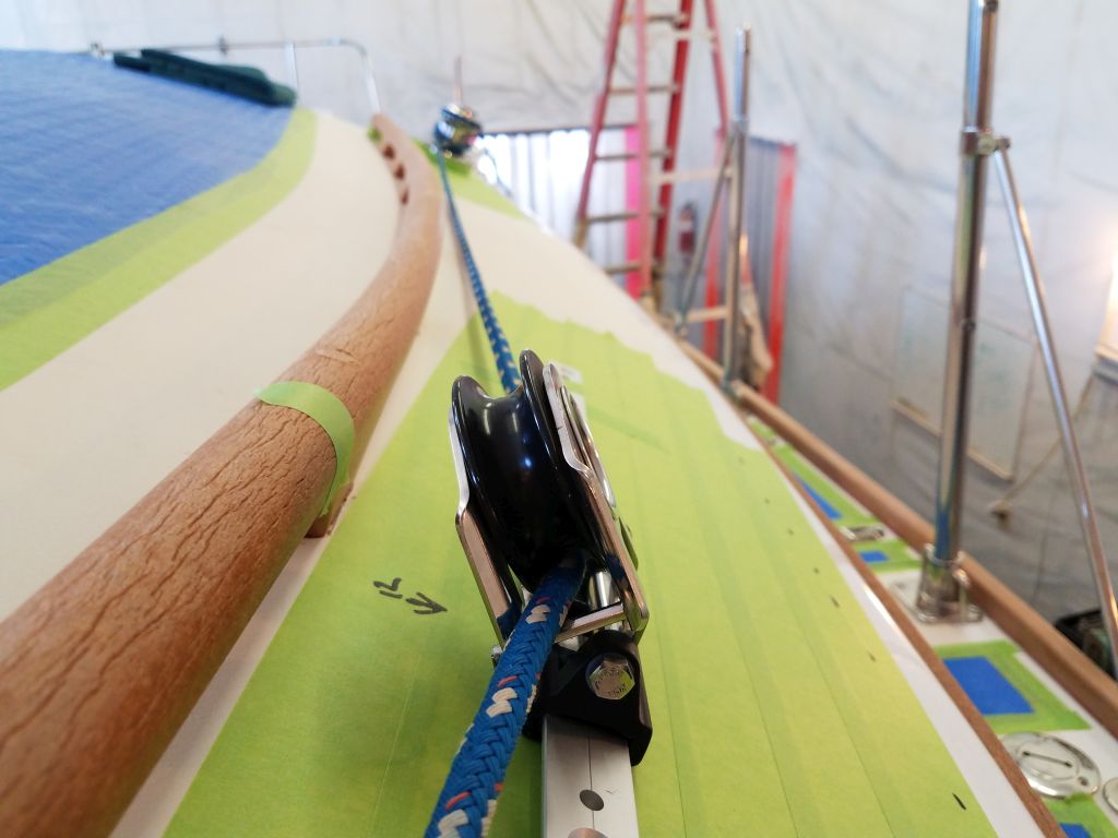
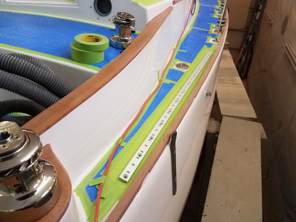
With the tracks thusly placed, and taped in place with the lead car installed in the center of the track, I used a line to mock up the sheet lead, satisfying myself that it would be fair all the way to the winch, not only from the ideal mid-track position, but also from the forwardmost position.  With minor adjustments, the initial layout worked as I’d hoped.

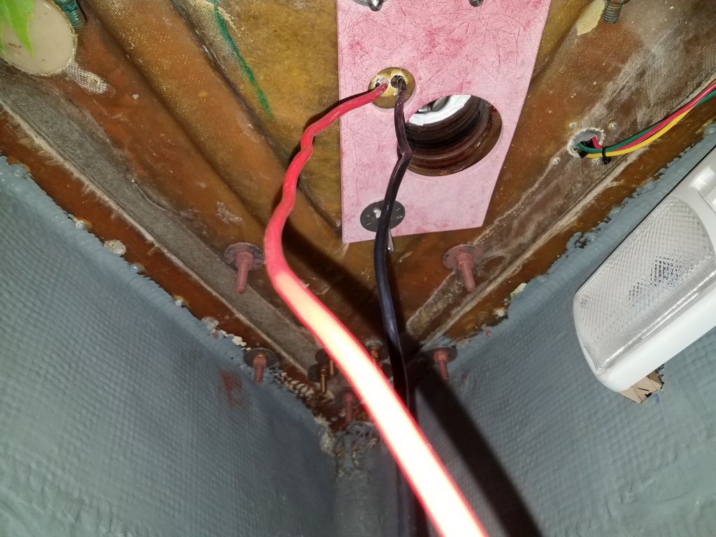
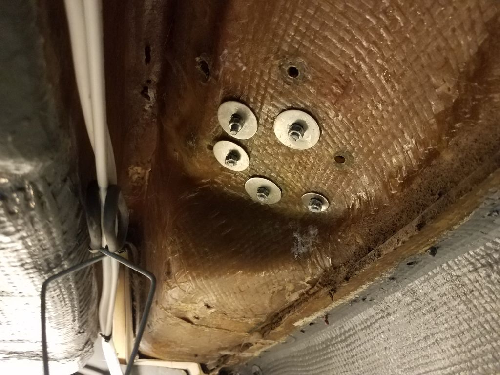
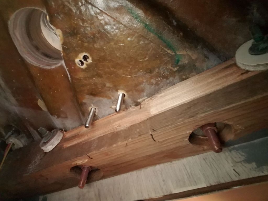
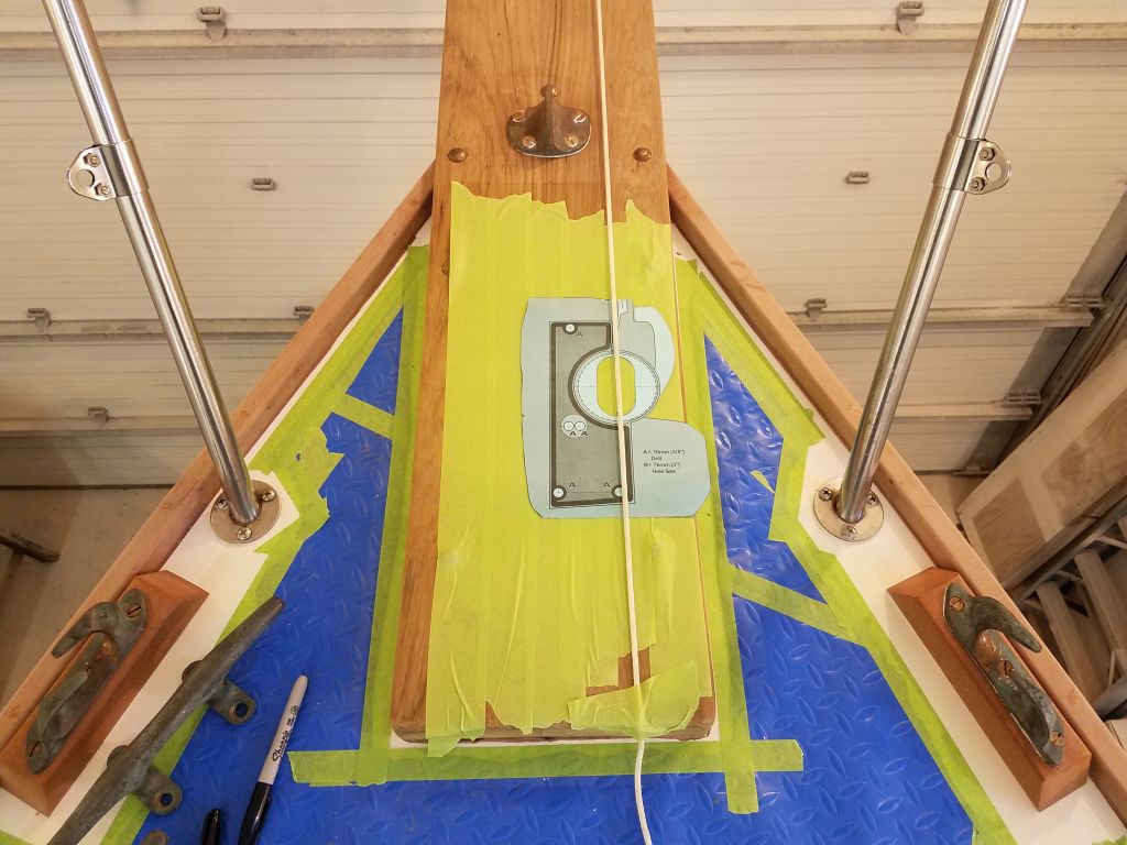
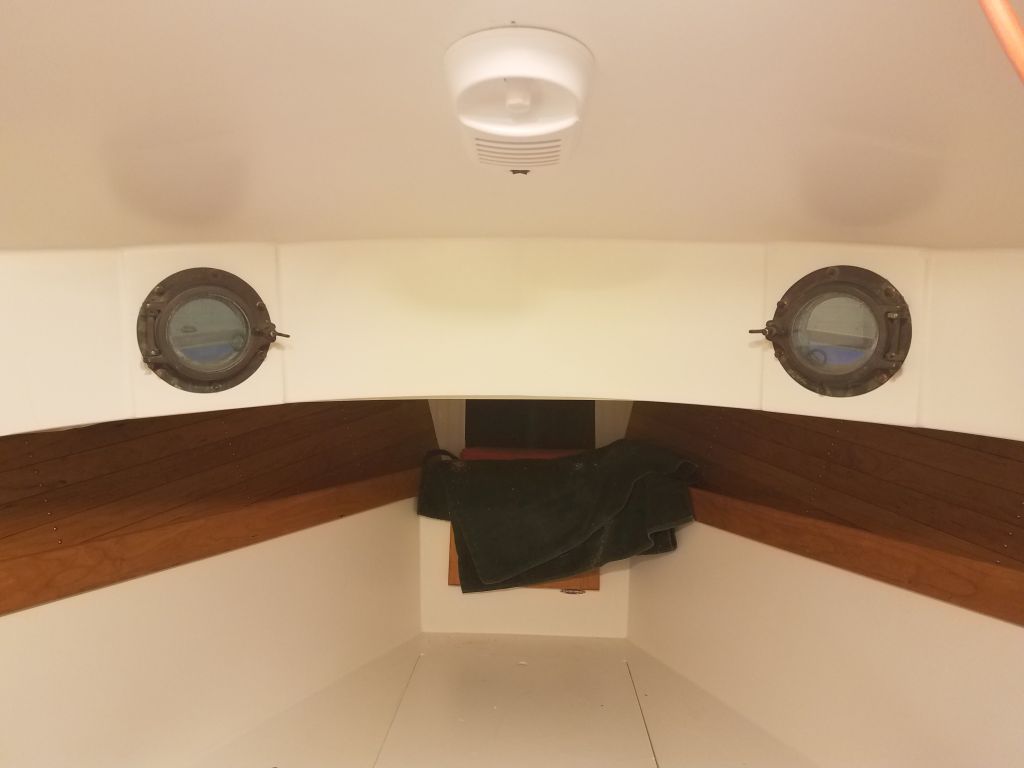
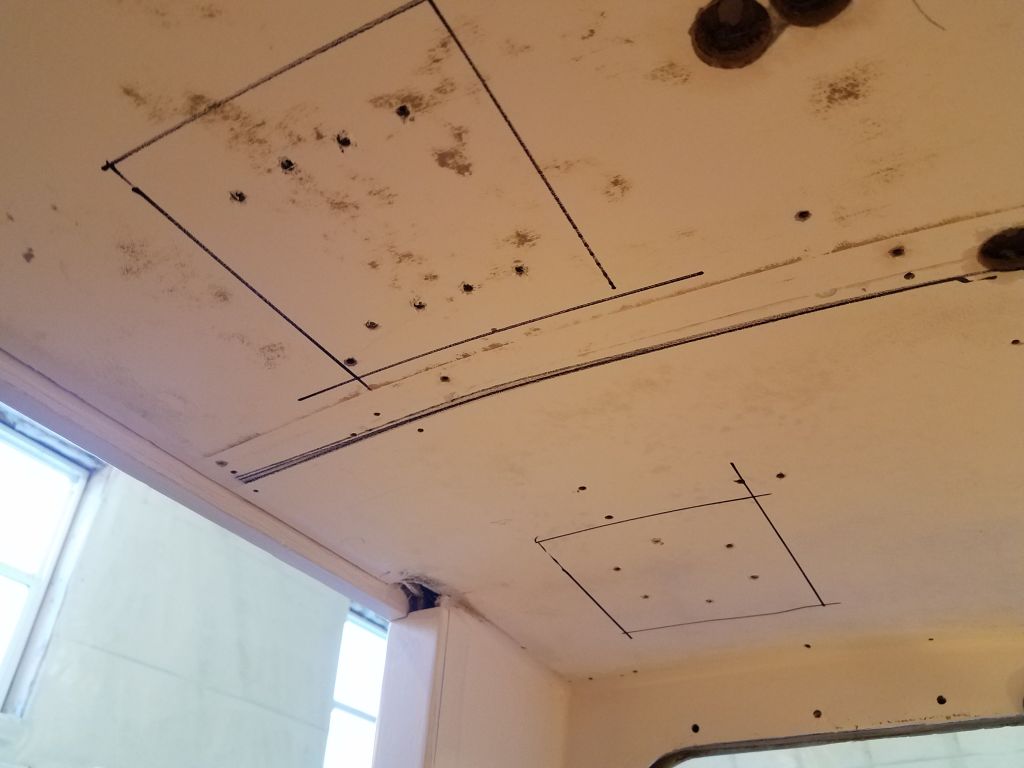
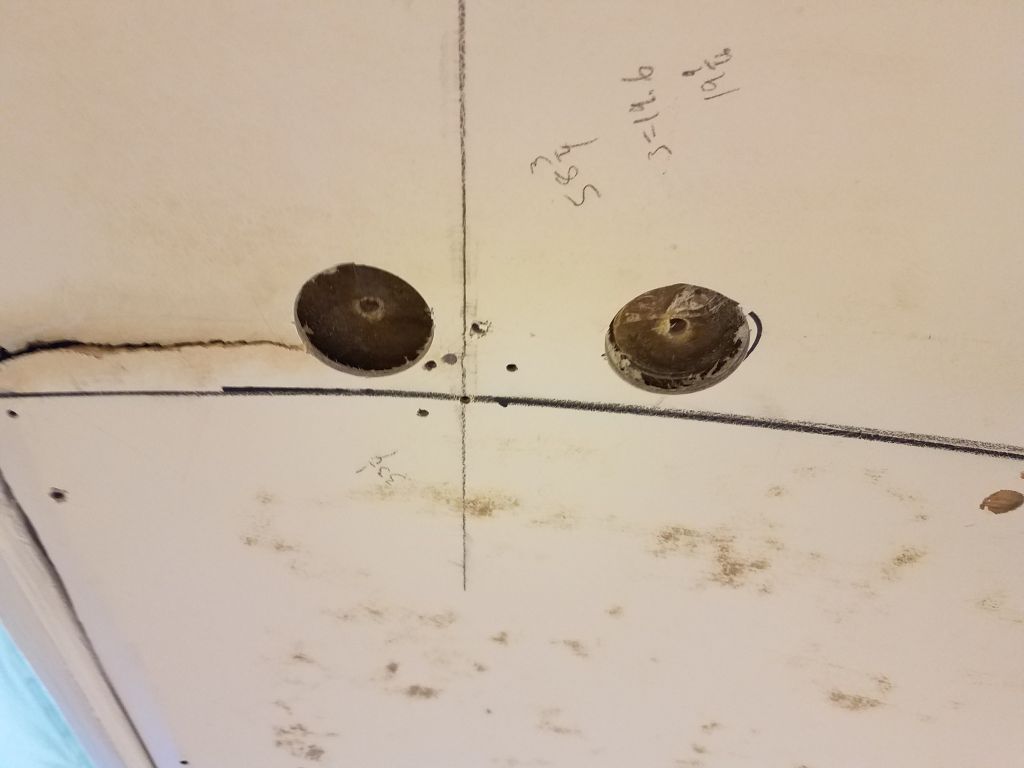
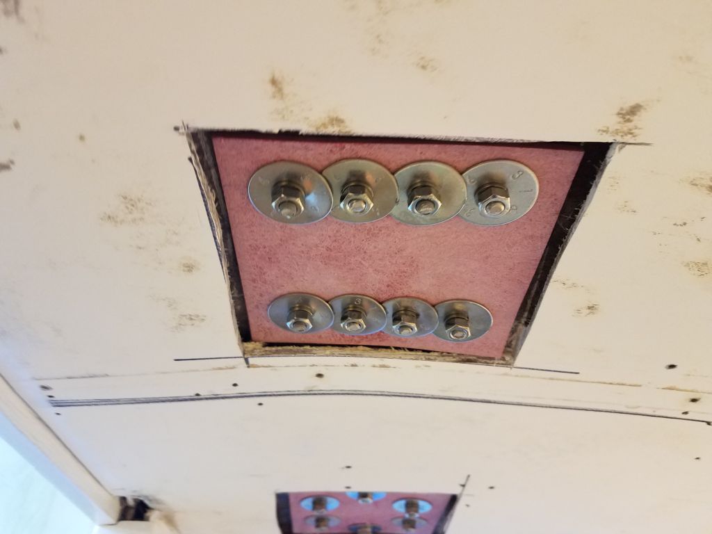
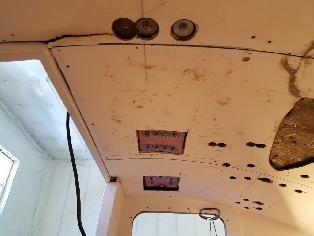
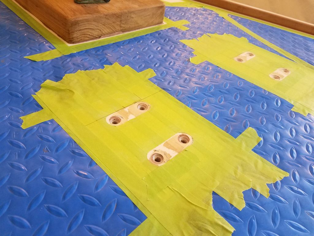
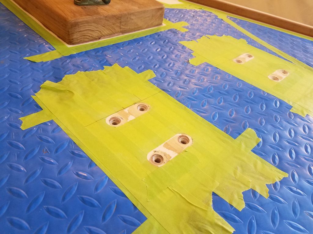
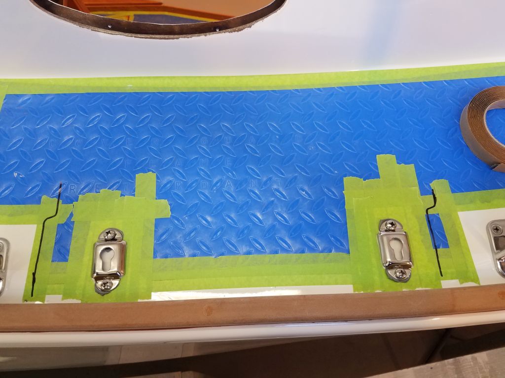
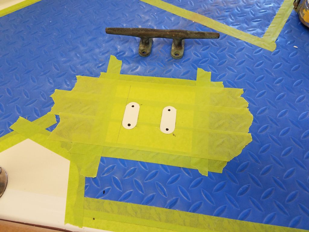
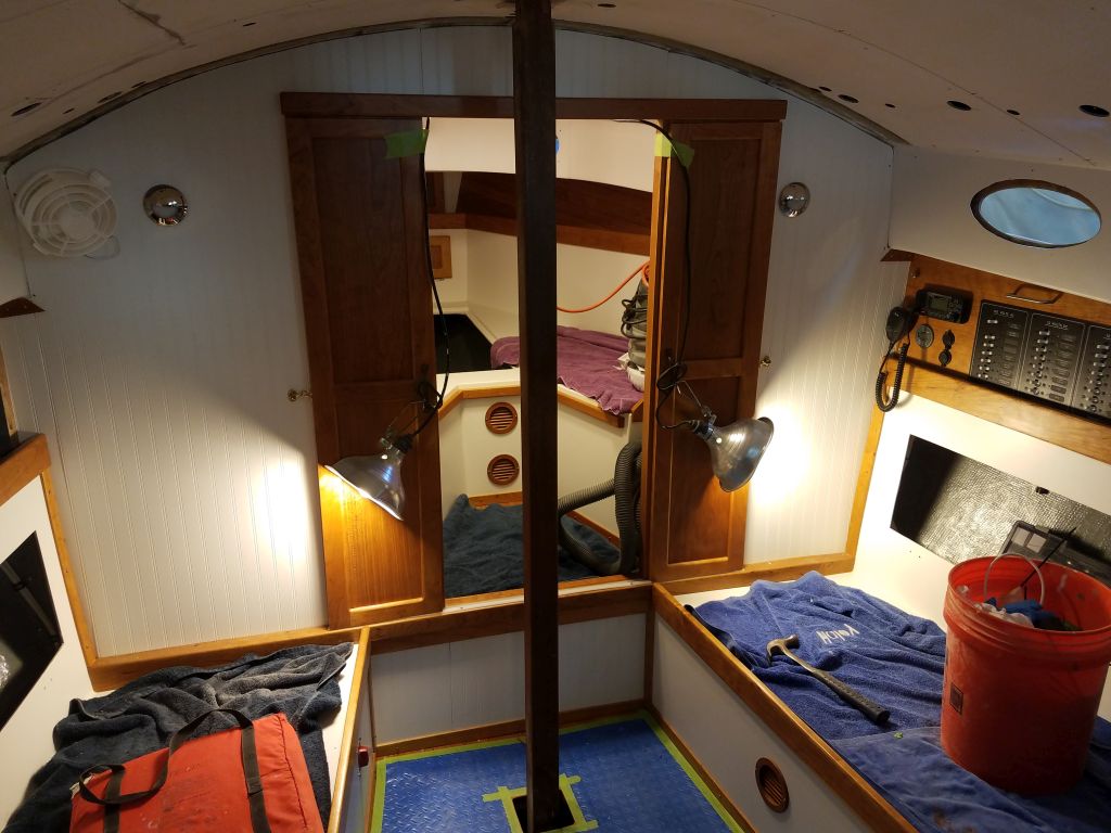
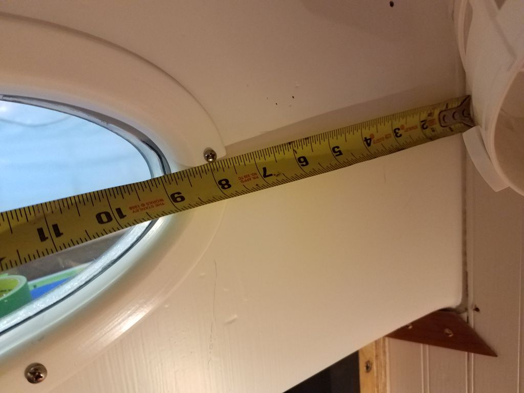
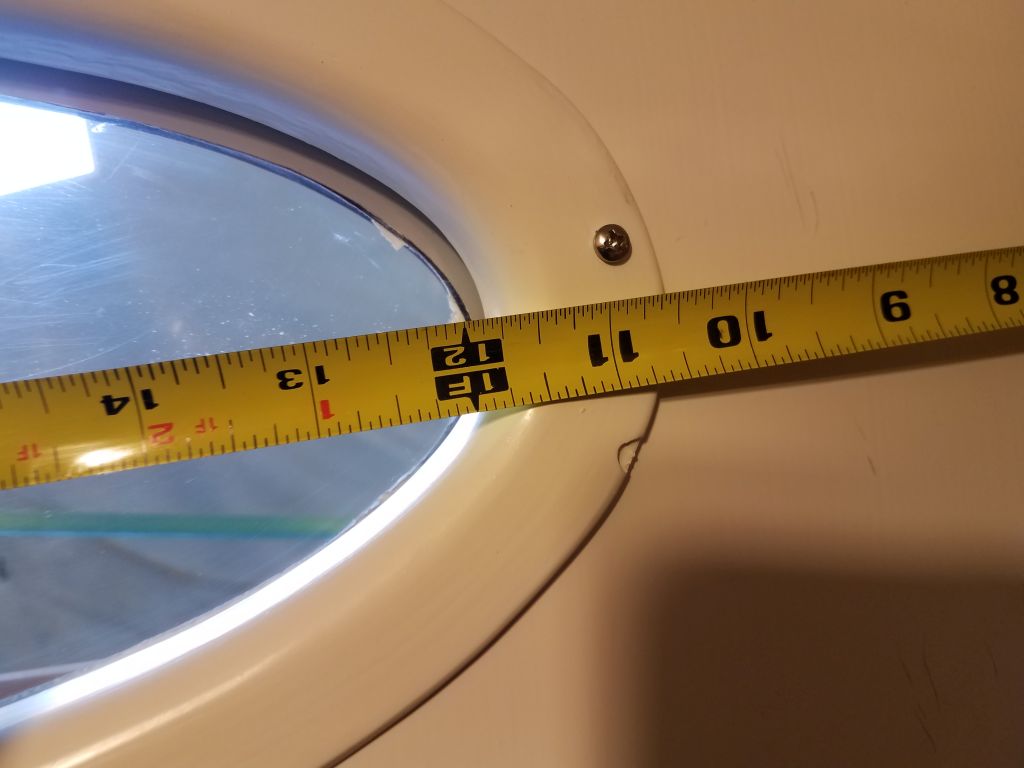
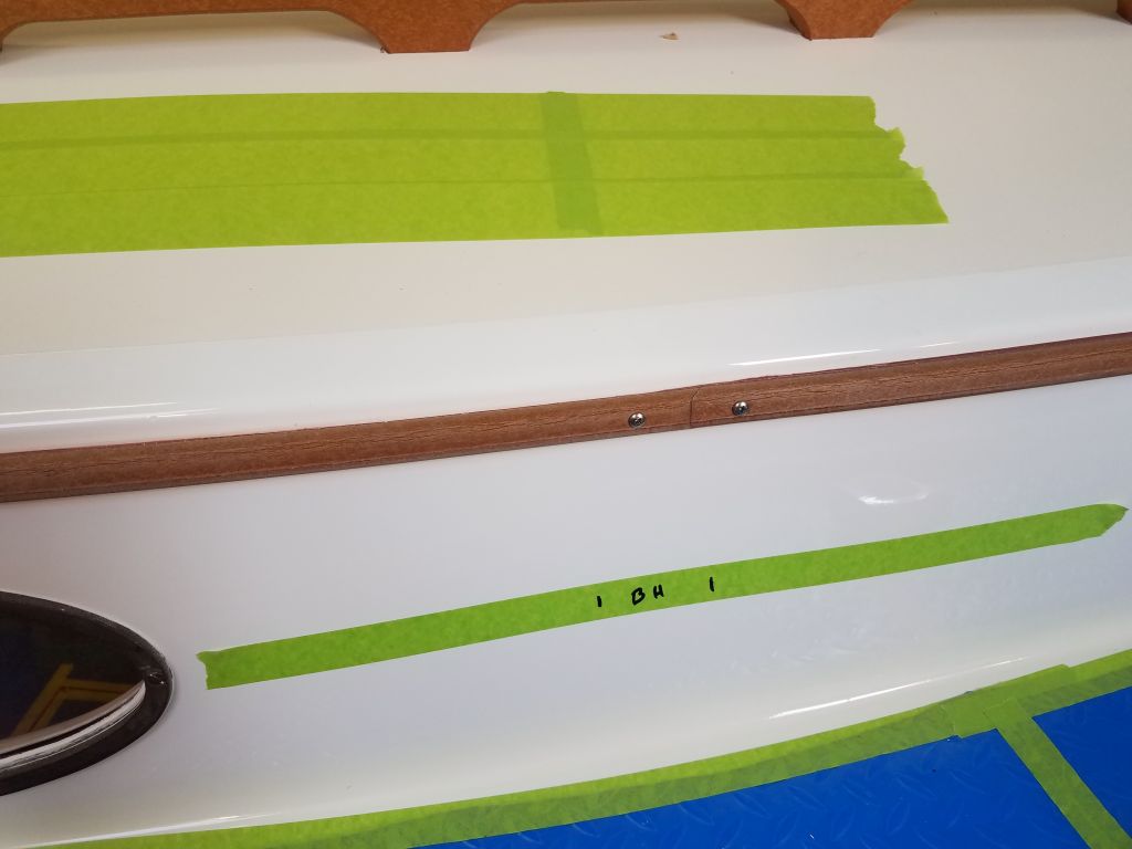
A final consideration before I went ahead with installation steps was to see where the track fell in relation to the main bulkhead:  I wanted to be sure the bolts cleared the bulkhead and didn’t end up in the middle of it.  In the cabin, I measured from the port openings on each side to the bulkhead, then transferred these measurements to the exterior so I could double check the track placement.  As it happened, the forwardmost fastener was a couple or few inches aft of the bulkhead, which was ideal since it meant there’d be no more holes required through the finished overhead in the forward cabin.

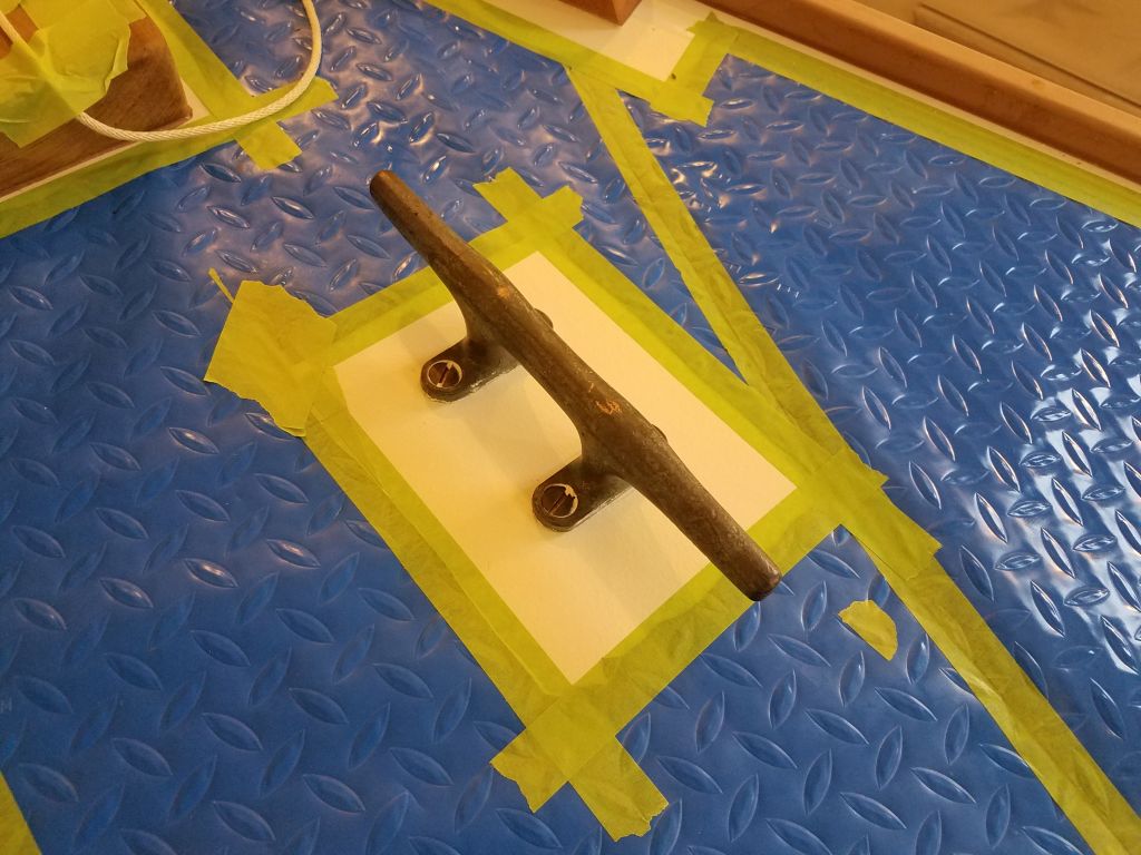
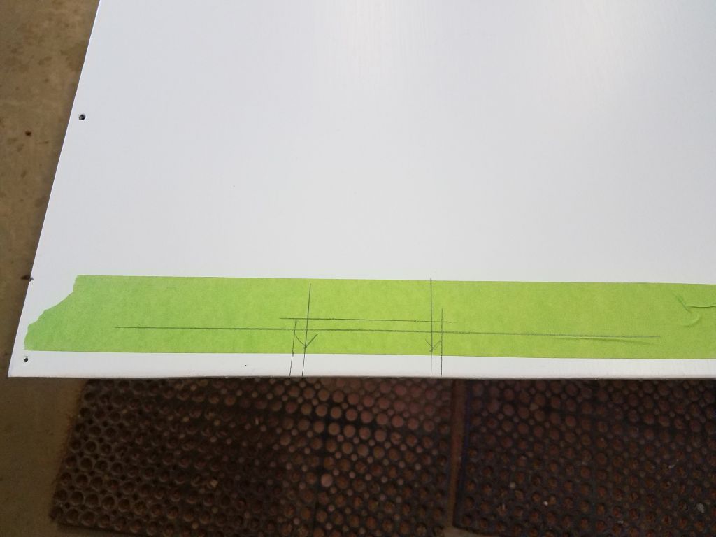
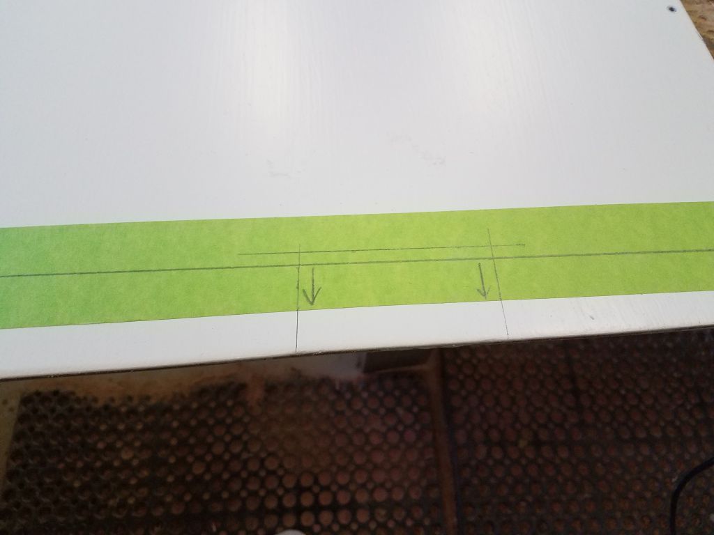
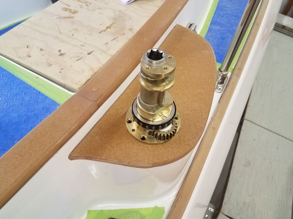
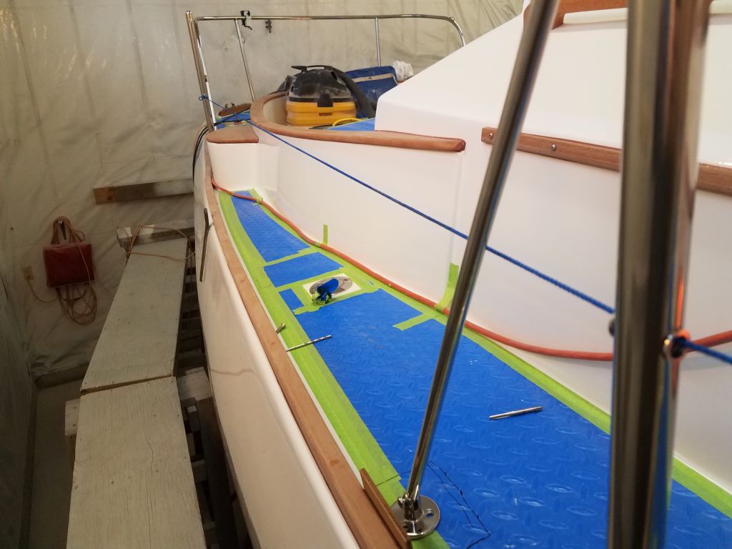
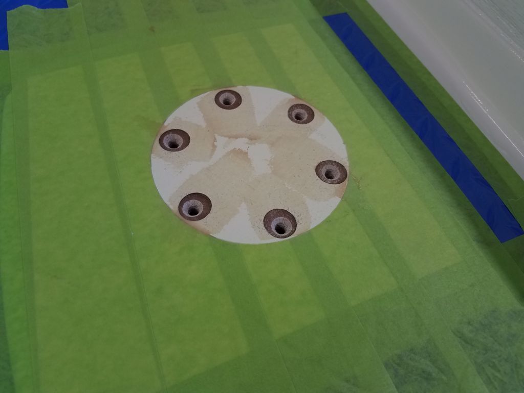
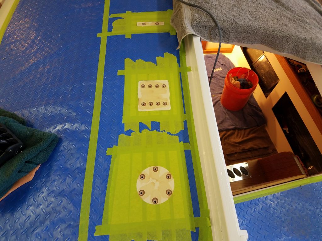
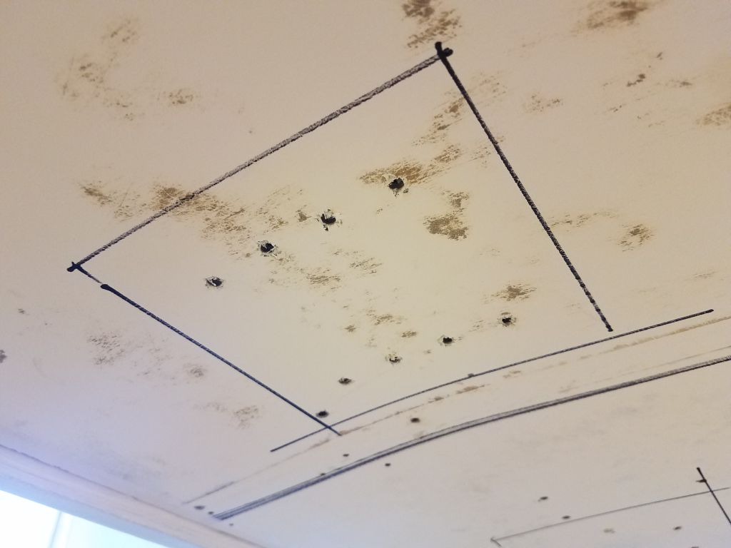
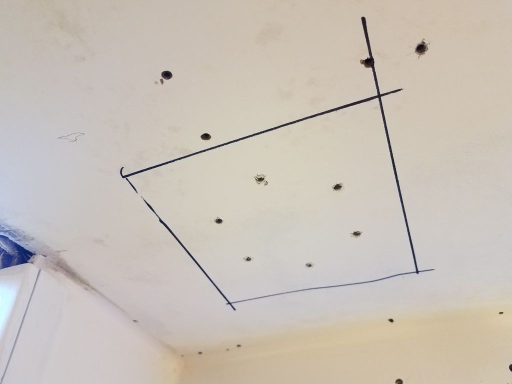
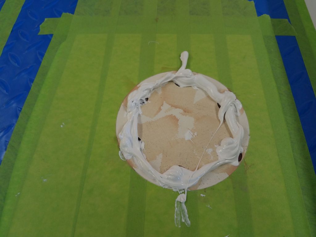
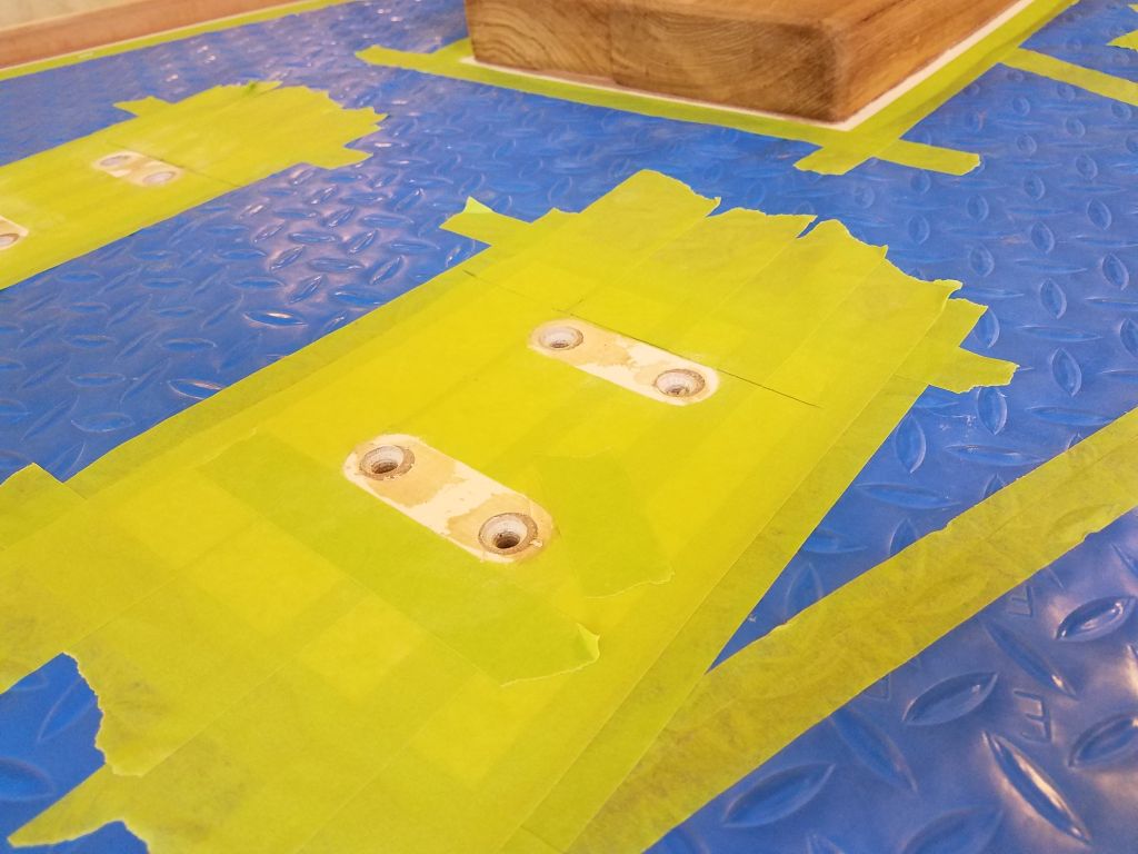
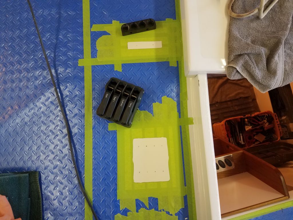
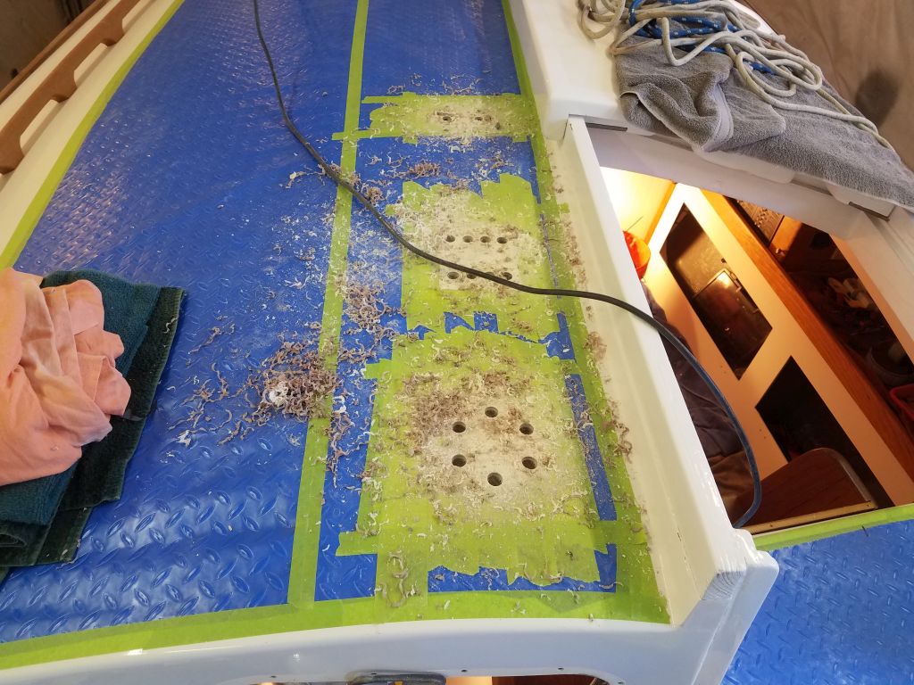
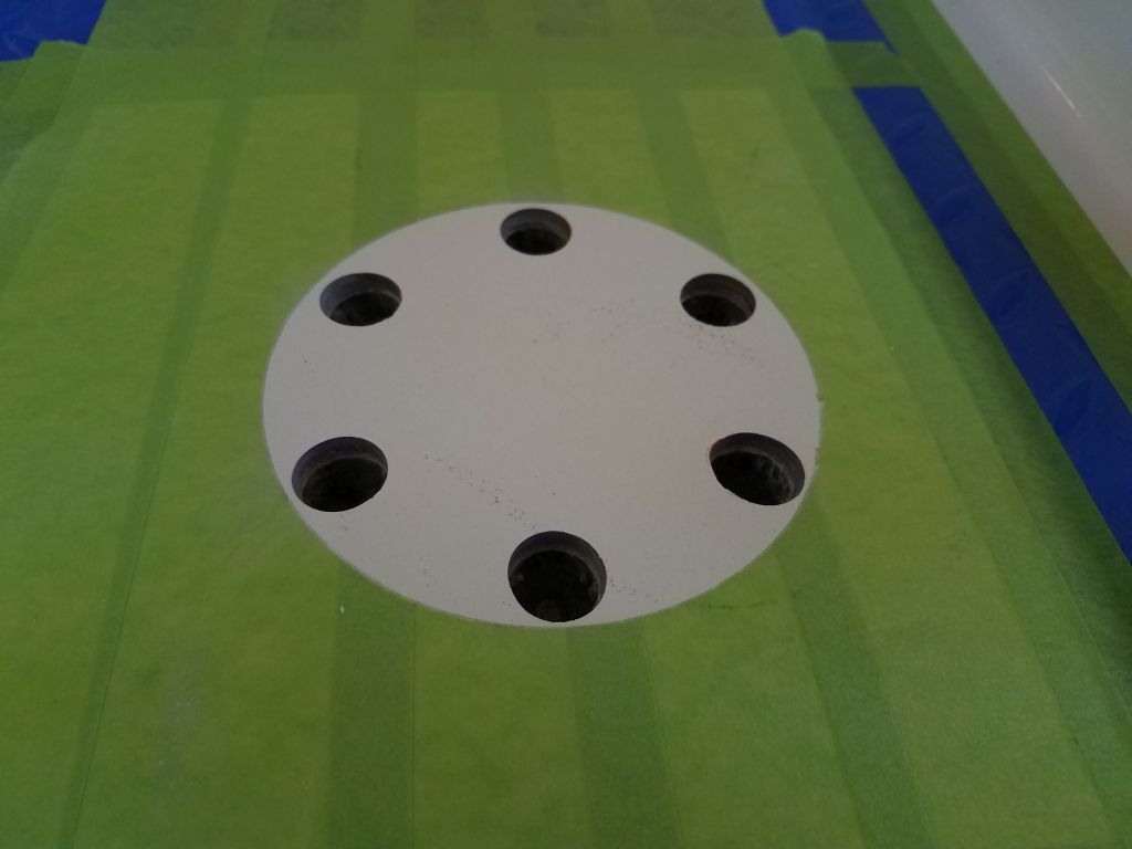
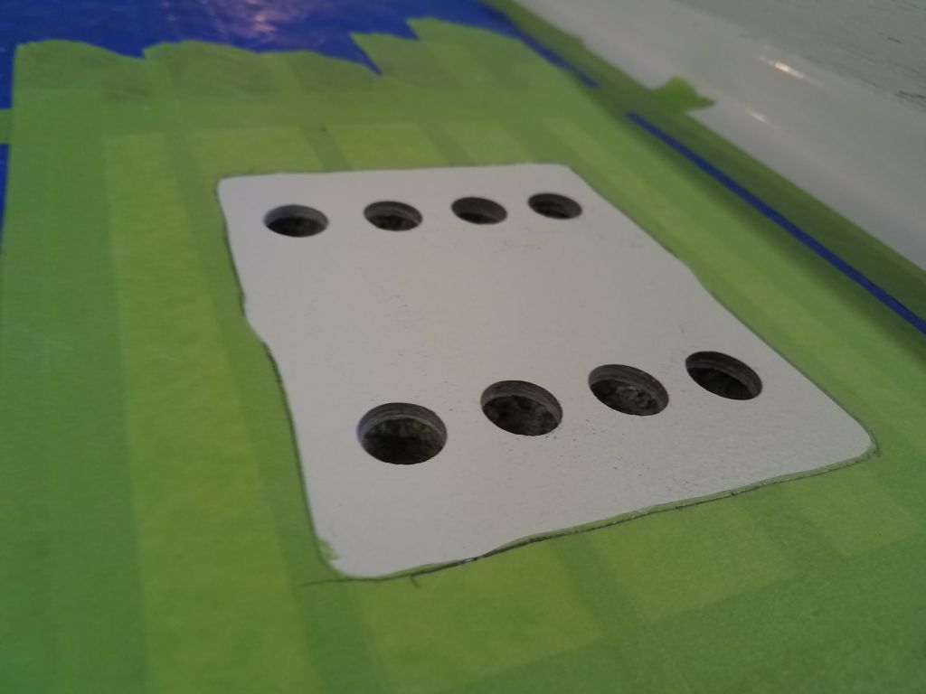
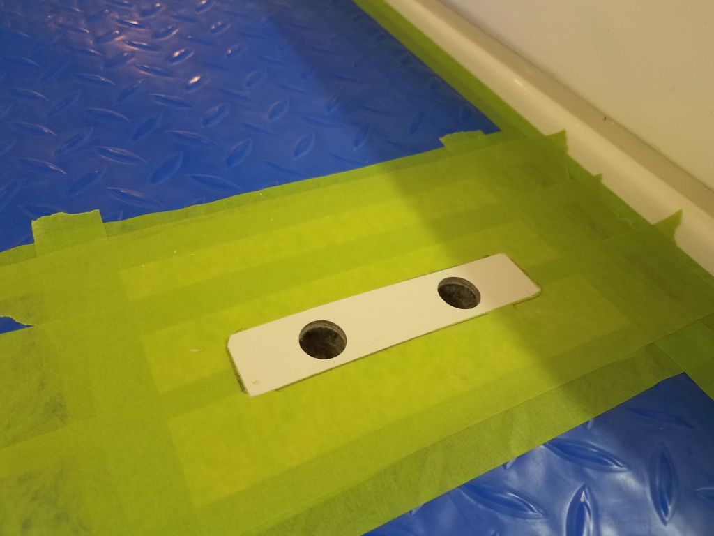
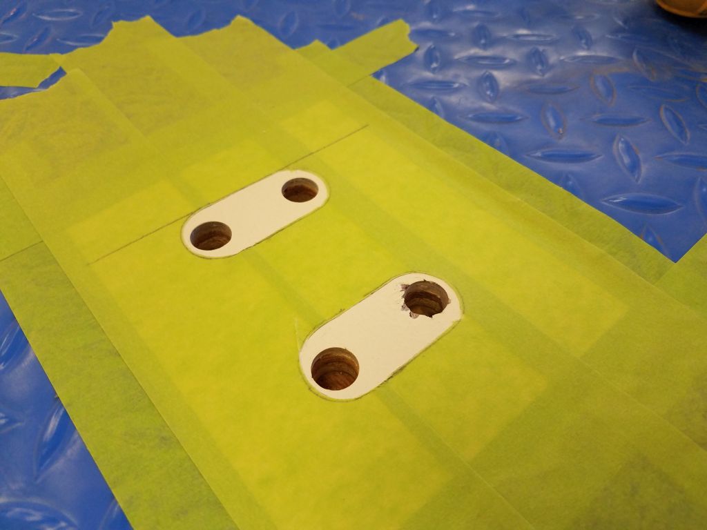
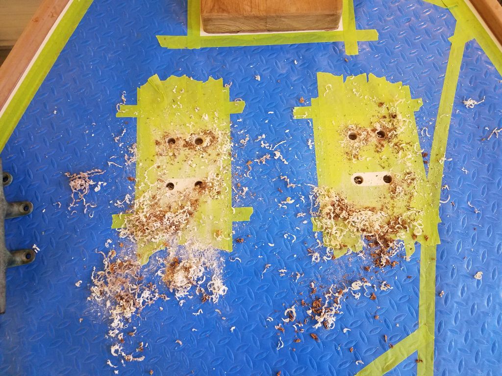
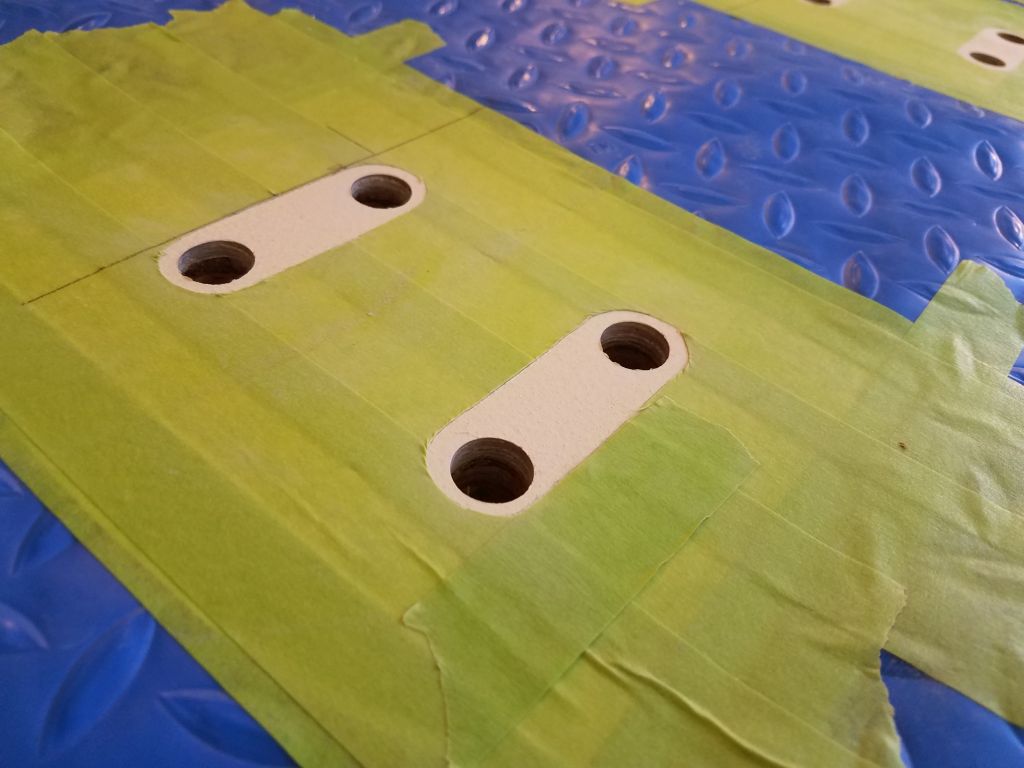
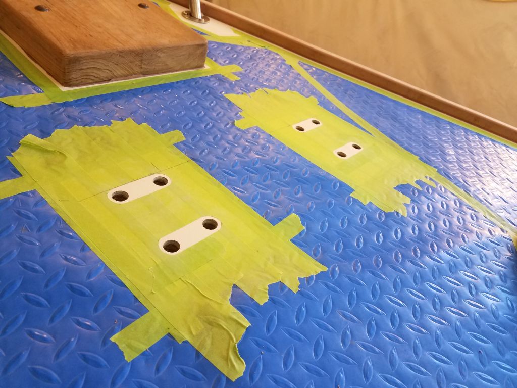
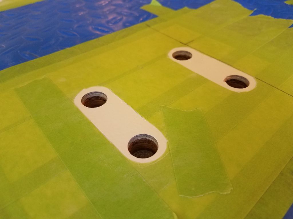
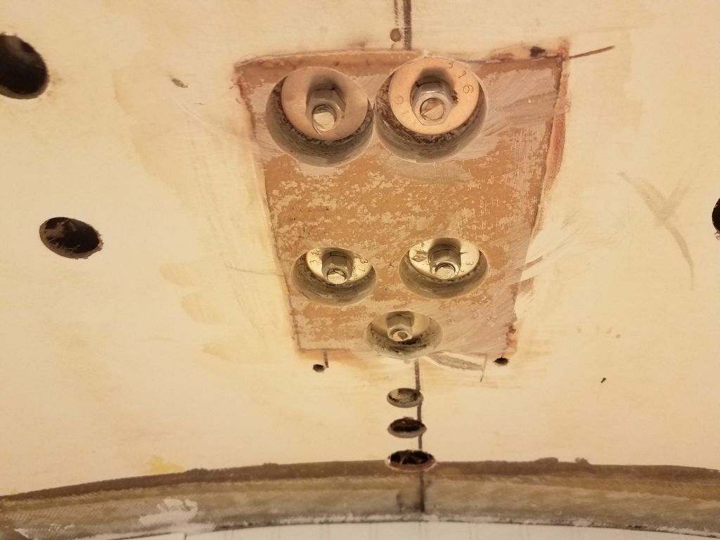
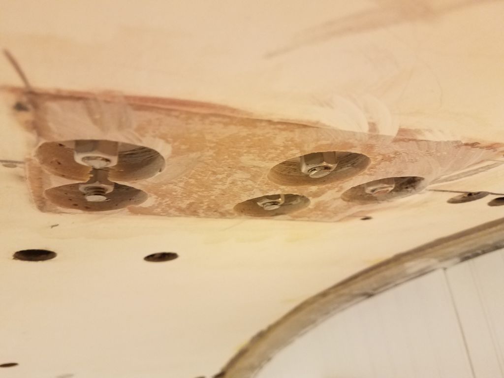
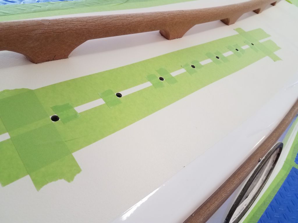
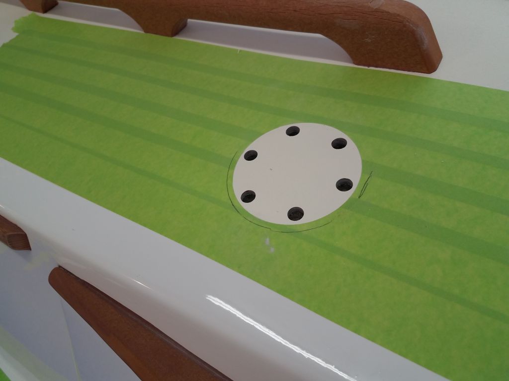
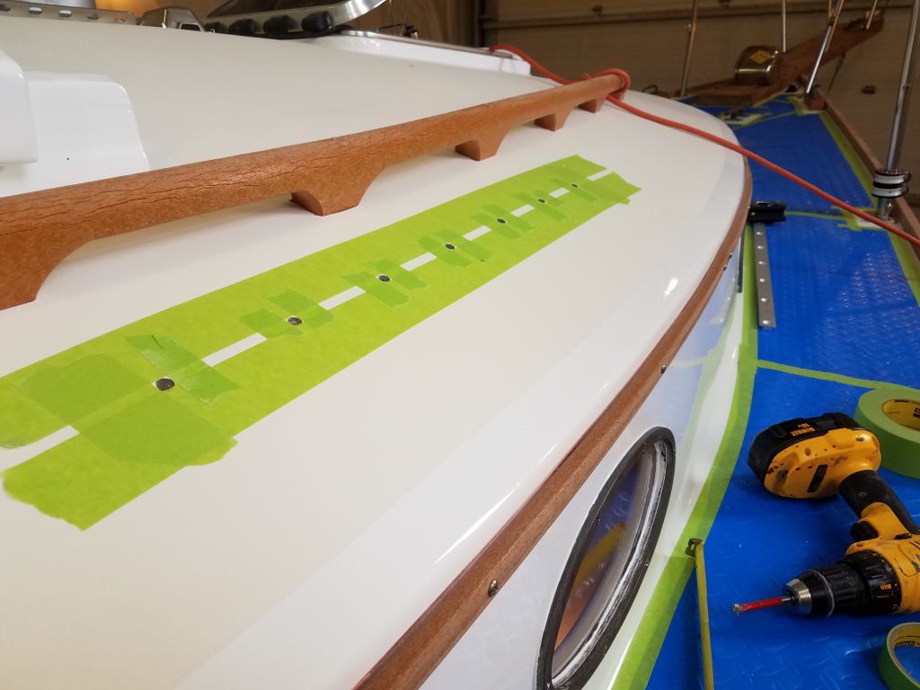
With the locations finalized, I marked the holes for the staysail track, then drilled out the top skin and core in the usual way.  At the winch location, I cut away the masking tape in way of the base, then aligned the winch as I wanted it (and in accordance with the winch instructions) and marked and drilled out the core in way of those holes as well.

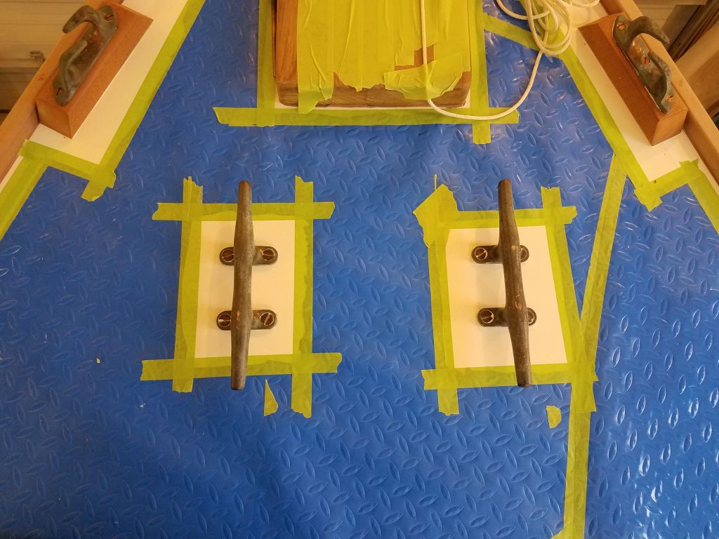
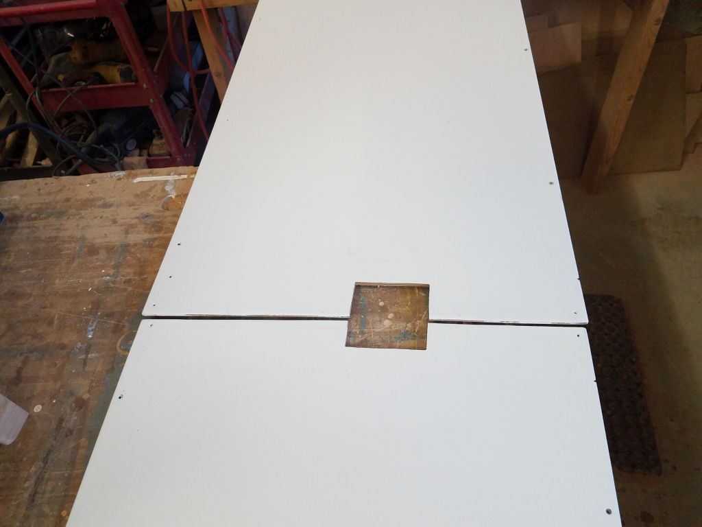
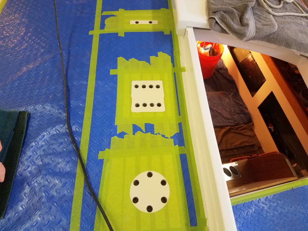
Laying out and preparing the fastener locations on the starboard side went more quickly, since now I could transfer measurements from the port side with no need for mockups and trials.

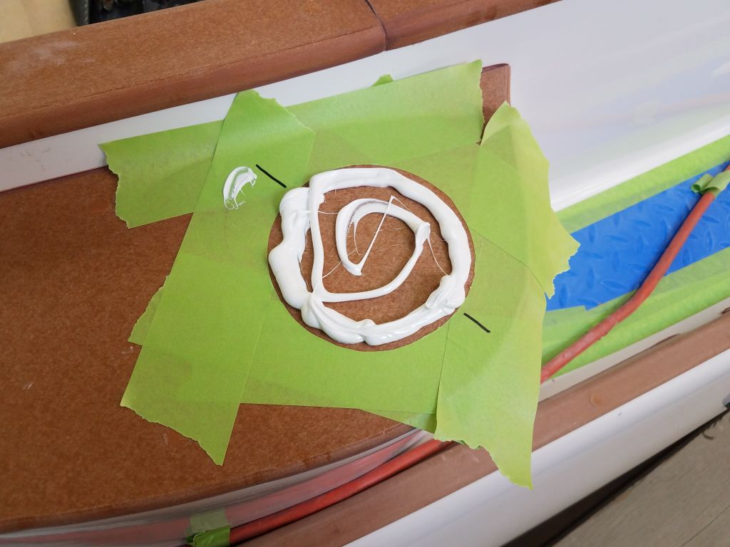
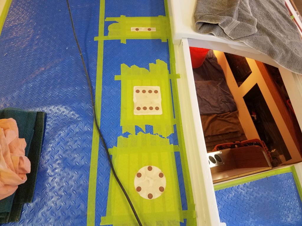
Afterwards, I filled all the new holes with a thickened epoxy mixture.

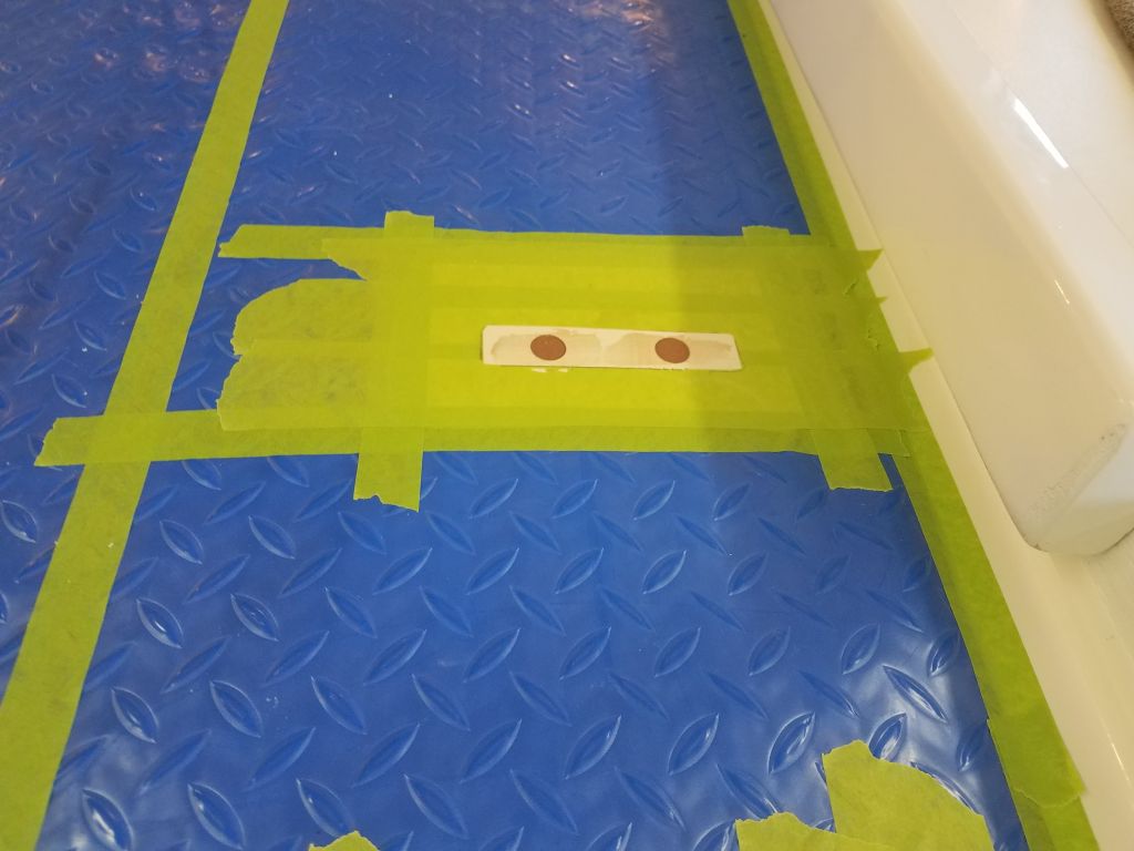
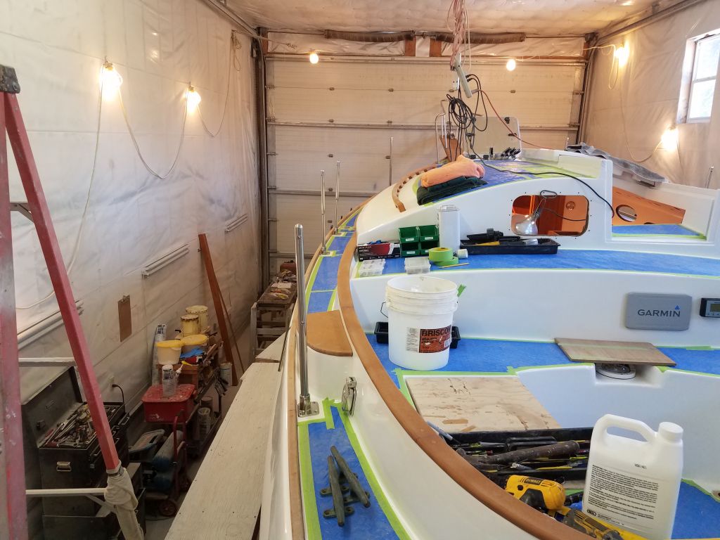
To round out the day, I got started on the layout for the jib/Yankee tracks, which was more straightforward since I knew where they had to go all along.  Still, I needed to do some final positioning, and, again beginning to port, eventually settled on a position 1/2″ from the toerails at each end, and centered between the winch island and the stanchion gate brace at the forward end.

With these basics, I repeated the process on the starboard side.  Here, the distance to the gate brace at the forward end was somewhat longer, a result of how I’d had to cheat the positions of the port-side braces in order to fit around the water tank fill, so this resulted in a slightly different base placement.  I kept the measurement from the winch island consistent (6-3/8″), so the tracks were the same from side to side.

For now, I was out of time, so I left final hole preparation for next time.  I hoped the tracks would be in the solid fiberglass portions of the deck on each side, but I’d find out for sure when I started the hole prep.

Total time billed on this job today:  7 hours

0600 Weather Observation:  29°, clear. Forecast for the day:  Sunny, 39°

Scupper 239

Tuesday

I spent most of the morning on the deck hatches, starting with the final installation of the lazarette hatch hinges, which I bolted through the deck after drilling and tapping the screw holes through the epoxy-filled patches from last time.  I finished up for now with a gasket inside the lid, and then covered the top of the lid with more protective plastic to prevent damage during the rest of the project.

I had a couple latching options on hand that I planned to install in the near future, but I wasn’t sure which one to  choose, so for the moment I moved on to the cockpit lids.  For these, I purchased stainless steel piano hinges, which would be a stronger installation than the original shorter hinges that had long failed by the time the boat arrived here.

For each hatch, I had to cut the hinges to length, which I did with a grinder and cutoff wheel, then laid out and dry-installed the hinges with a couple screws before drilling all the remaining holes.  I installed the hinge to the locker lid with butyl tape sealant and however many screws were required by the hinge.

On deck, I positioned each hatch in the middle of its opening, and repeated the hinge installation process on the back edge of the locker gutters.

I added a gasket around the inside of the hatch opening, then covered the tops of the hatches with more of the plastic covering before installing hold-down, lockable latches to the hatch.

Though I wasn’t ready to install it just yet, I went ahead and drilled, tapped, and prepared the mounting holes for the mainsheet padeye and riser block.

The plastic molded battery boxes I’d found much earlier in the project were a near-perfect fit for the specified batteries, but weren’t quite tall enough for the cover to fit properly.  Accounting for the terminals, and space for the cables, I needed a couple more inches of height beneath the lids. I used some foam blocks that came with the batteries in their shipping boxes to simulate the final height needed for the lids.

The lids would be a protect the battery terminals, and while they would provide a minor role in overall battery securing, the overall means of preventing battery movement would come from different means, so to extend the tops for my purposes I came up with a plan to add plastic extensions to the lids, and plastic cleats on the boxes themselves to support the extensions.  I chose ABS plastic since it had good qualities for the intended purpose, and I thought it matched the original box construction as well.

As needed, I cut and bolted 3/4″ thick plastic cleats to the sides of the battery box, then cut and bolted 1/4″ x 4″ plastic extensions to the box, leaving room for the cable openings.  This essentially covered the box but left adequate clearance within for the terminals and wiring; the extensions were strong enough that I could later strap over the top of the box to help hold the batteries securely.

With the prototype built, I saw a need for some small additional cleats to help hold the extensions in place, but the basic concept was sound and strong, and I continued the process with the additional four boxes, managing to cut all the plastic for the remaining work and install it on one additional box by the end of business.  I’d continue with the additional boxes over the coming days.

Total time billed on this job today:  7 hours

0600 Weather Observation:  25°, clear.  Forecast for the day:  Chance of snow and rain showers, 35°

Scupper 238

Monday

With my days for the immediate future slightly truncated at each end as we settled in to new routines with a new puppy at home, I got a somewhat late start with the day’s work.

Four of the new deadlights had had the weekend to cure in place, so now I removed the shims from inside, leaving the acrylic lenses firmly in place.  I removed the protective plastic film from the inside surfaces.

With the wedges freed up, I could go ahead and install the remaining two lenses on the starboard side, using the same techniques as on the previous four.

The next step towards completing the installations was to lay out and drill fastener holes for the exterior bronze trim rings.  These rings performed no particular structural purpose whatsoever, but finished off the openings from the outside.  Since the bolts to secure the rings would also pass through the new lenses, the trim rings would also help secure the plastic, though in this installation that was a secondary benefit.

Not that it probably mattered, but during removal of these deadlights long ago I’d marked each trim ring for its location, and now, using the appropriate ring for each port on the port side, I dry-fit the rings, drilling and tapping for #8 machine screws at the six screw locations.  I held the ring temporarily with the two end screws while drilling and tapping the remaining four holes.  Afterwards, removing the trim ring, I milled the usual small countersinks in the cabin side.

With the three ports on this site thusly prepared, I applied sealant to the perimeter of the openings and installed the trim rings permanently, cleaning up excess sealant afterwards and finishing up my removing the exterior protective plastic film from the lenses.

I repeated the process with the starboard forward port, the last of the original four.

Inside the boat, I installed nuts and washers on the new machine screws, then finished up the installations with the interior trim rings.

In a couple days, I could repeat the final processes on the two starboard after deadlights, but for the moment I took a few minutes to finish up a couple small jobs from the list, starting with replacing the screws on the anchor windlass circuit breaker, swapping the ones I’d used originally for some black-finished stainless screws that better matched the panel.  I also removed the protective paper from the forward hatch–a small thing, but a good sign as it signaled the end of the project was nigh, and there was no longer any reason to hold off.

I’d held off installing the cockpit locker hatches and lazarette hatch as long as possible, but now it was time to start thinking about final installations, starting with the new lazarette hatch in the poop deck.    I laid out a pair of small yet hefty stainless hinges on the aft side, and pre-installed the hatch side of the hinges with sealant and small bolts before marking the hole locations on the deck and removing the core from around the four screws in the usual way.

Afterwards, I laid out and prepared the fastener locations for the mainsheet padeye and riser, even though the riser was still in primer only and awaiting its final finish.  With these holes prepared, along with the hatch holes, I filled all the holes with a thickened epoxy mixture, finishing up the day by spec’ing and ordering some materials I’d need to finish up the battery installations in the coming days.

Total time billed on this job today:  6 hours

0600 Weather Observation:  33°, light rain, 2″ snow overnight. Forecast for the day:  Rain showers, then cloudy, 39°

Scupper 237

Friday

I got started again on the windlass installation, starting back in the forward compartment, where I finished up the wiring there–a simple sentence that belies the two or more hours required to make the final connections between the rocker switch and deck-mounted remote, run new 2AWG cable between the battery (positive distribution buss) and windlass circuit breaker and onwards to the contactor box, as well as the negative cable required.

With the wiring complete belowdecks (other than the leads from the windlass motor), I prepared the windlass itself for final installation with sealant around the base and wiring holes, after which I bolted it in place with the new backing plate and blind windlass studs.  The cables connected to the windlass were just a few inches too short to reach the contactor box, so I had to spice in additional wire in order to make the run and complete the windlass connection at the contactor box.

This took most of the morning to complete, but before lunch I had time to work more on the light near the companionway.  I realized that I could install the aftermost overhead panel on the starboard side now after all, since the staysail sheet winch would end up above the head on this side. so with that epiphany I went ahead and installed the small panel, and connected the little light fixture with removable wiring so the panel could be pulled down as needed.  I discovered belatedly that the spade connectors I had on hand weren’t fully insulated at the terminal ends, so I added some black tape to prevent contact between positive and negative wire terminals.

After lunch, and contemplating my ongoing list, I decided with some trepidation to start the work on the deadlights’ installation.  On this boat, the deadlights–i.e. the small elliptical fixed ports in the cabin sides–featured an unorthodox construction in which the port lens (acrylic plastic in this case) was secured directly to the inside of the cabin trunk behind the liner, and then independently trimmed on each side with a bronze trim ring on the exterior, and a plastic one on the interior.  It was frankly a bizarre and un-ideal setup, but we’d long ago come to terms with it, and after substantial surface preparation much earlier in the project (required to remove the gobs of silicone that had originally been used to secure and bed the ports), I felt like securing the new lenses in this way would be at least effective, if not how I would have designed it.  In any event, I knew that the new installation would exceed the quality of the installations I’d removed during the beginning of the project.

Ports and deadlights usually end up being one of my least-favorite installations on any boat:  there’s something about them that is simply un-fun and usually highly fussy, and, working alone, there are frequently many times where additional help would be useful but not forthcoming.  So with all this in mind, I was not sure why I decided to tackle this on an icy, story Friday afternoon, but apparently there was karma in the air.  I looked forward to these installations being done, but at the same time I’d continually postponed the task for some time since I didn’t really want to do the installation.

Completely unsure how this process would work out, I decided to start with cutting out the new acrylic lenses for the two deadlights in the forward cabin as a sort of test.  Using the old lenses as a guide, I cut out the new ones; the very construction of the ports meant that high accuracy was not critical here, as long as the lenses could fit through the openings in the liner, and had enough overlap to be bedded to the inside of the cabin trunk once in place.  For the task I’d procured a couple sheets of clear acrylic, which in this case was covered with a clear plastic protective wrap rather than paper.

With just the two lenses for now, I attempted a dry-fit to see how this would work.  My plan was to bed and adhere the lenses to the inside of the cabin trunk with the same lightly-adhesive polyurethane sealant I favor for deck hardware, and wedge them tightly in place while the adhesive cured.  So to start, I dry-fit the lenses, determining how to angle them into the narrow space between the cabin liner and cabin trunk beyond, and used wooden shims to hold them tightly in place.  This actually worked better and more smoothly than I thought it would, and, pleased so far, I used a pen to mark the protective plastic from outside so I could remove the plastic from the bonding surfaces where needed.

The openings on the port side, which had been affected by whatever long-ago trauma had created so many “interesting” fiberglass situations on that side,  were relatively rough on the inside, and I worried that this would make sealing tough, but as it happened the lenses fit fairly well despite that, and while the starboard side was smoother and more even, I felt that the port lenses would work just fine as well, which was a relief.

Removing the lenses to the bench, I cut along my lines to remove the outer strip of the protective plastic, exposing the acrylic for bonding.  I added a thin strip of masking tape inside the cut for extra protection, as I planned to leave the covering in place while the sealant cured, but wanted to be sure I could cleanly remove it later.

I cleaned the raw fiberglass inside the cabin trunk with acetone, then applied a bead of sealant to the outer  parts of the two lenses and carefully angled them into the openings and positioned them as needed, using shims to hold the plastic tightly against the fiberglass.  It was easy to see the sort of seal I was getting, since the sealant bead was visible from within as I pressed the ports into place.

From outside, I added an additional bead of sealant around the edges to fill any gaps, and smoothed out the bead so it was flush with the masking tape.  This was easier than I had expected it would be, which pleased me.

This went so much better and more quickly than I’d anticipated that I decided to continue, but not wanting to shake things up or risk a superstitious jinx, I continued by cutting out just two more lenses–this time for the port middle and after locations–and repeated the whole process:  dry fit, marking, masking, final preparations, and installation.

I would have liked to have completed the final two lenses on the starboard side in the main cabin, which would have given all six the full weekend to cure, but the wide gaps between the liner and cabin trunk on the port side had exhausted my supply of shims, so I cut out the final two lenses and went through the dry-fit and marking processes with some little shim remnants, but left final installation till next time when I could free up some of the wedges.  I could have made up some new wedges to get the job done, but I’d been at it long enough and didn’t want to push my good luck, so I thought it made sense to call it good for now and simply wait till next time to continue.

Total time billed on this job today:  7.25 hours

0600 Weather Observation:  29°, light freezing rain.  Forecast for the day:  Freezing rain to sleet and snow, 32°

Scupper 236

Thursday

My first task of the day was to install the bow cleats with new 5″ machine screws.

Next, I installed the jib sheet winches, using several long lengths of 1/4″ fastener as needed for the thick winch islands.

I spent the bulk of the day on various aspects of the windlass installation, starting with confirming the position I’d laid out last time, using the windlass itself to confirm the position I’d marked on deck.  Once I was satisfied with the position, I marked the hole locations and drilled for the mounting studs, wire passage, and a large 3″ hole for the anchor rode.  This was a long process and taxed even my second-biggest corded drill.

I installed the mounting studs to the windlass and tested the fit of the new fastener holes, checking clearances below.  Clearance was tight near the wooden beam near the chainlocker bulkhead, but OK for a backing plate and washers.  I used the supplied windlass base gasket to lay out a backing plate to fit.  To seal the inside of the large anchor rode hole, I applied some epoxy resin throughout.

The owner’s choice for the main windlass control was a wired remote, which required a plug on deck.  I chose to install this well forward on the starboard side, where it would be accessible yet out of the way of normal traffic–plus it was a location where the wires would be hidden in the chainlocker.  I pre-wired the bottom of the switch and noted the wire colors and specific terminals for later reference, then installed the switch with its supplied gasket and some butyl tape around the center housing and screw locations.

The final installation of the windlass hardware would have to wait till the epoxy cured, so I moved my operation down below and led the wiring from the new deck switch down and into the little locker at the forward end of the v-berth, where I also installed the windlass control (or, as it’s called in the documentation, contactor) box.

The windlass came with a basic rocker switch for operation, which the owner foresaw as an emergency backup only, so we agreed to install the switch in the forward cabin.  I chose a location adjacent to the door into the now-windlass control locker and installed the rocker switch and little panel, installing the three wires (with the same colors as their counterparts to the deck switch) to the back of the switch before final installation.  The wires from the two control units would be conjoined later at the terminals on the contactor box.

Finally, I chose a location for and installed the supplied 70-amp dedicated circuit breaker for the windlass.  This needed to be close to the battery (or positive buss), yet accessible, and with the intricacies of the boat, this more or less dictated the position in the center of the v-berth cutout, where there was a perfectly-sized space to accept the breaker panel.

With all the core installations and basic layout complete, I hoped to complete all the windlass wiring and installation details next time.

Total time billed on this job today:  8 hours

0600 Weather Observation:  22°, snow just started.  Forecast for the day:  Snow and sleet, a few inches’ accumulation, 32°

Scupper 235

Wednesday

To install the vent for the waste tank, I began with a small hole drilled from inside the boat in my chosen location, then went outside to enlarge the hole to fit the vent.  I installed the new vent with plenty of sealant, keeping the vent opening angled slightly back to avoid water inflow when the boat was heeled.  I wanted to install the hose and finish the vent plumbing, but I didn’t have the right hose clamps on hand for the 5/8″ hose, so that would have to wait till later.

Next, I installed the bow chocks and riser blocks with new long bronze machine screws into the already-prepared deck and holes.

I’d been in kind of a hurry to install the large port in the galley earlier, as the day was running out and I wanted to have it done then, but now I realized I should have changed the gasket in the opening port, since the old one was in bad condition.  I found it was easy to remove the opening part of the port (I should have done so before installing the spigot, which would have made life easier), and I had the 1/4″ square gasket material in stock, so replacement was quick and easy.

Preparing ahead for its eventual installation, I installed a series of wire mounts inside the channel in the forward side of the mast compression post, starting just at sole level and mounting them every so often up to the top.  Then, I measured the height of the cabin table (about 30″), and installed a little chart light with USB port on the aft side of the post about 12″ above the table top, running the wires through the post into the channel.  Afterwards, I laid out and temporarily installed the wooden cover over the wiring channel, though I planned to remove this before installing the post later.

Mike from the rigging company was here for a few hours during the morning to install the new masthead sheaves, reeve the halyards, and install the rigging on the mast, as well as measure for the new lifelines.

I spent the first part of the afternoon working on the lighting and switch wiring in the starboard aft end of the cabin, near the companionway.  The owner had requested a small overhead light here, for which I’d built a round base some time earlier, as well as a switch to operate this light along with the identical fixtures in the galley.  I hoped and planned to hide the wiring for the light and switch behind and in the gaps around the molded interior liner at the bulkhead.

There was a large hole in the original overhead here where a stove pipe had once passed, and this was the general location I planned to mount the new light, so I measured the center of the hole and transferred it to the new plywood overhead panel so I could drill a hole for the light fixture and wiring.  I had some issues trying to screw the wooden ring to the plywood, so instead I glued on the ring and would later install the small round puck fixture once the overhead panel was finally installed.

The little switch would be mounted in a wooden cover plate I made earlier–needed to allow for the depth of the switch and the blind wiring in the location–so once I determined a mounting location, near the companionway opening, I drilled an access hole and then fed in the wires intended for the switch.  I could also lead the wires for the light fixture behind the bulkhead and through the old overhead into the opening where the light would be; the wires fit nicely in the large space next to the bulkhead liner, and these gaps would be covered by the cherry trim that I’d already made for the purpose.

I’d hoped to lead the switch wires straight out through the backing block and to the switch, but I found that the design and depth of the switch, and the terminal ends, didn’t allow this, and after trying a few things I eventually turned around the mounting block and enlarged the hole in the fiberglass behind (not shown) to give some more room for the wiring and terminal connections in the hollow back side of the cherry mounting block.  I wasn’t sure which terminal on the switch was which, but it’d be easy to swap the wires later if needed once I had the boat powered up.

I’d make up the final wiring for the light fixture later, when I installed the overhead panel.  For now, I needed to keep this area open pending installation of the staysail sheet winches.

With overhead on the mind, and the day where I could finally install the fresh new panels approaching, I temporarily installed–one at a time–the forwardmost panels on each side so I could use the marks I’d made on the old overhead to mark the new overhead panels in way of the compression post.  By aligning a ruler with the marks I’d made previously, I could transfer the position of the post to the new panels.

Down on the bench, I cut out the openings in each panel, allowing an extra 1/4″ on all sides for clearance, Clarence.

With just a bit of time left in the day, I worked with the windlass  template to set up the initial layout on the bowsprit, using a line tied to the anchor roller to ensure the proper alignment for the anchor chain to the gypsy.

Total time billed on this job today:  7.75 hours

0600 Weather Observation: 33°, mainly clear.  Forecast for the day:  Mostly sunny,  30°

Scupper 234

Tuesday

First thing, I finished up the gate braces’ installation, a straightforward task.

I’d already marked the fastener locations for the inner forestay attachment point on the bowsprit, so now I double-checked the marks, then drilled the holes slightly oversized for the 5/16″ bolts that would secure the hardware.  Then, after masking off the bare teak around the base, I installed the inner forestay with new fasteners and sealant.

At the cockpit and winch islands, I laid out the positions for the new jib sheet winches, ensuring ample clearance between the winch handles and the nearby stanchions before marking the winch island for the fastener locations.  Since the self-tailing strippers on this particular model winch were fixed in one position only, I aligned the winches according to the desired position of the strippers on each side of the cockpit.

Afterwards, I used a long bit to drill through the winch islands for all the 1/4″  fastener locations, then used the bit, inserted so it was just penetrating the underside, to measure the depth of the holes at the deepest points, which I marked with tape above.  Because the underlying (original) winch islands were an angled molding, the underside of the islands was also angled, so the fastener length required varied from inboard to outboard accordingly.   The outer depth was about 6″, and I was able to find and order  7″ long flat head fasteners to suit the bill; the shorter versions for the inner locations were easier to find.

After some final prep and fastener/tool collection, I turned to the bronze ports:  three small round ones, and the large one over the galley.  Beginning in the forward cabin, I dry-fit the ports to check their fits in the existing openings.  As expected, the clearance was extremely tight, and I needed to assess how best to seal the ports during installation.  These ports fit from the inside out, and were to be secured with four bolts from the outside.    All the fastener holes were in place, but I reamed them out a bit to ensure easy passage of the new fasteners.

For installation, I applied sealant around the inside of the round opening, so that the port spigot would push through it as I installed it from the inside.  Though I normally wouldn’t seal the inside mounting flange of a normal (i.e. trim ring) port installation, here I felt that the additional layer of protection was necessary since there was so little space for a guaranteed good seal around the spigot, though it turned out that the sealant appeared to do the job well once I’d installed the ports.

With both ports sealed and installed from the inside, and aligned with the mounting holes, I went on deck and installed the new bronze fasteners with ample sealant around their tops and heads.  Then, I secured the ports with nuts and washers within.

I finished up the installations by cutting the excess bolt length and installing the original bronze cap nuts over the exposed fastener ends, then cleaning up the excess sealant on the outside of each port.

I repeated the installation process with the similar round port in the head, though here it was a tight fit into the space from inside.

I finished up the day with the last bronze port installation over the galley.  This port was traditional in that it featured a trim ring from outside, so bedding this port was more straightforward.

Total time billed on this job today:  7.25 hours

0600 Weather Observation: 25°, mainly cloudy.  Forecast for the day: Partly sunny, slight chance of rain or snow showers after noon, 38°

Scupper 233

Monday

In the morning, I drove to a nearby shipping terminal to pick up a pallet of 10 new 300 amp-hour, 6-volt batteries:  8 for the electric motor (48-volt system), and the remaining two for a 12-volt house system.  Once back at the shop, I broke down the pallet and unloaded the batteries piece by piece.  Each weighed somewhere around 90 lb.  In the coming days and weeks I planned to finalize the batteries’ installation in the boat.  I test-fit one in one of the battery boxes I’d purchased some time before.  As expected, the tall battery maxed out the height of the box (these were the tallest boxes I could find that otherwise fit the batteries’ general dimensions), and in order to make the lid fit properly I might need to come up with a small modification, but for now I left that problem for another day.

Meanwhile, I prepared for a meeting at the shop with my local sailmaker, who arrived to measure and discuss details, as well as assist in planning the locations of the jib and staysail tracks.  Afterwards, I turned to the day’s first real work:  installing the stern chocks and oarlock socket.  The boat had not come with stern chocks; the ghosts of their locations was still visible on the poop deck when the boat arrived here originally, but no chocks were installed, so I purchased a pair of bronze chocks to suit.  I built a riser for the port chock so lines would clear the toerail, angling the short ends for appearance.  On the starboard side, I found I had to make a new riser block to incorporate both the chock and the oarlock, as space there was at a premium and two separate risers didn’t make sense.  While I was at it, I made angled risers for the two original bow chocks as well.  Later, I discarded the double-length riser seen at the bottom of this photo in favor of a new one with a different end design that better matched the requirements of the location, as seen in later photos of the installation process.

After pre-drilling the risers with oversized holes for the fasteners, I used the blocks to mark the deck accordingly and went through the usual steps of masking off around the new fixture, and the normal drill/tap fastener hole preparation before installing the new hardware with sealant and new bronze and stainless fasteners as needed.

With the new riser blocks and bow chocks, I prepared the foredeck for the final installation, marking the block locations, masking off, and drilling and tapping the fastener holes on both sides (though I only photographed one side, apparently).  I needed fairly long 1/4″ bronze fasteners for the chocks, which I didn’t have on hand, so I ordered what I needed, along with some extra-long 5/16″ bolts for the foredeck cleats since I found the ones I had on hand weren’t long enough since that part of the foredeck also incorporated an extra layer of reinforcing plywood beneath the deck proper, plus the 3/4″ thick wooden backing blocks required for cosmetic purposes in the exposed mounting location in the forward cabin.  Now everything on the foredeck was ready for final installation as soon as I received the needed fasteners; I also planned to install the bronze fitting for the inner forestay, which installation I’d been putting off since it would mean another highly uncomfortable foray upside down into the tiny chainlocker to finish.

To properly support the stanchions and lifelines at the new gates on each side, I needed to install gate braces fore and aft, at either side of the opening, so with the braces in hand I prepared their installations.  These particular braces featured a hinged tubing connector that allowed installation despite the protruding ferules at the lifeline locations.  Starting on the starboard side, I laid out the braces, ensuring the braces stayed clear of the lower lifeline by stringing an analog line with some twine.  Maintaining my now-standard 1/4″ spacing to the toerail, I marked and prepared the deck for the eventual fasteners that would secure the small bases.  The decks here were solid fiberglass on both sides, so but for a lack of time before the end of the day I could have completed the installation; as it was, it would be quick to finish up the installations next time.

Total time billed on this job today:  8 hours

0600 Weather Observation: 23°, mainly cloudy.  Forecast for the day:  Mostly sunny, 41°

Scupper 232

Friday

Easing into the day with a simple yet necessary task, I installed the four pulpit brackets that would support the lower lifeline attachments.

The cabin top was ready for the final installation of the new hardware, so to begin I drilled, tapped, and countersunk all the fastener holes for the winch, rope clutch, and fairlead.

Belowdecks, I marked and cut away the liner in way of the winch and rope clutch, and drilled two 1-1/2″ holes with a hole saw at the fairlead fastener locations.  This exposed the underside of the deck proper.  For the winch and rope clutch, I prepared backing plates from fiberglass sheeting to fit in the new openings.

I began the installation with the fairlead, which was furthest forward and the simplest installation overall.  I applied sealant and installed two 1/4″ bolts.  I discovered that I’d cut away the liner from the wrong hole beneath (there are many old holes in the liner), and had to cut a new opening for the inboard fastener on the fly.  These holes accepted large fender washers to secure the fairlead.

Next, I installed the winch base with sealant and six bolts, using the backing plate and fender washers beneath.  There was just enough room so that the backing plate and nuts fit  just flush with the existing liner, which was important since the new overhead panels fit closely to the old liner.

The rope clutch admonished the user not to use polysulfide or polyurethane sealant, and since my standard sealant is a light polyurethane, I used butyl tape instead  to install the rope clutch with its eight bolts, installing the new backing plate and fender washers beneath.

This completed the hardware installation for the aft-led control lines.

Next, I drilled, tapped, and countersunk all the fastener holes for the stern cleats, ladder brackets, and bow cleats.

The varnished wooden backing plates for the bow cleats weren’t yet ready for installation, but I could proceed with the stern cleats after making a pair of fiberglass backing plates to fit.

To gain access to the underside of the deck at the ladder mounts, I had to cut away more of the liner to expose the deck.  I hated to do this, but there was nothing for it, and these new openings were between the existing openings I’d cut for the lifeline stanchions, so when I built trim to cover the cutouts I could simply plan to do it in one fell swoop.

Because I didn’t want a mess of sealant to ooze into the open space of the bracket mounts required for the top of the ladder, I chose butyl tape to seal the brackets, and bolted them in place with large washers beneath.  The ladder fit well on both sides, but I’d have to later trim to length the standoff brackets on the ladder so it would be properly supported by the hull.

With that, and after a bit of boat and shop cleanup, I reached the end of the day’s work.

Total time billed on this job today:  7.25 hours

0600 Weather Observation: 11°, clear. Forecast for the day:  Sunny, 39°

Scupper 231

Thursday

To begin the day, I finished up the new waste deck plate installation, a straightforward matter of the usual drill/tap/countersink/sealant process.  Afterwards, I secured the hose belowdecks.  All that remained to complete the waste system was the head installation, but I was in no rush to install that till I knew I was finished moving about in the tight space.

Next, I turned to the new deck hardware for leading some of the control lines aft from the mast to the cockpit.  In all, there’d be four lines coming aft:  main halyard; outhaul; reefing line; boom vang.  The new mast organizer plate had plenty of room for the four turning blocks required at the mast base, and I installed these now so I could mock up the lines leading aft.  It was a straight lead aft alongside the companionway, which greatly streamlined the overall installations ahead.

With a couple old shop lines standing in for the real things, I spent some time working out the final placement of a small 4-position fairlead, 4-position rope clutch, and a new self-tailing winch on the aft end of the cabin trunk, near the companionway opening.  I wanted to locate the fairlead in such a way as to keep all four lines as straight as possible, though with the outlying main halyard block on the port side, the line would necessarily take a bit of an angle.  But even so, the leads were straight enough to obviate any need for a fancy sheave-based deck organizer, allowing me to use the machined aluminum fairlead instead.  The first line I’d used during early layout for the main halyard (the line to port) was too large to fit through the rope clutch, so later in the process I replaced it with a smaller line seen in some of the photos.

After a while, I finalized the positions of the three pieces of hardware, and after preparing the deck in each area by cutting away the plastic deck covering and replacing it with masking tape beneath each fixture, I relocated and marked the base positions of all the hardware, and marked the fastener locations.  Then, with a 5/8″ Forstner bit, I removed the top laminate and coring from all the fastener locations, and, after cleaning up, filled the fastener holes with a thickened epoxy mixture in the usual way.

The pile of new stanchions on the aft deck was getting in the way, and with the bases all in place I could take a moment to clean out the little circle of now-cured sealant squeezeout within each base socket and install the stanchions with their setscrews.  On the starboard side, I added two furler line lead blocks to each of the forwardmost three stanchions, as these had to be in place before the stanchion was installed in the socket.  I’d already notified the riggers that the pulpits and stanchions were ready for them to come measure for new lifelines.

Continuing with hardware, I turned to the mooring cleats:  two at the stern,  two at the bow.  Starting with photos of the boat as she’d arrived, I positioned the stern cleats in generally the same areas, though I made some minor adjustments as I deemed proper.  In this case, the cleats ended up 6″ from the toerails, and 6″ aft of the forward stern pulpit bases.  This location kept the cleats out of the way and the poop deck fairly clear, while still allowing a fair lead to the eventual stern chocks at the taffrail.  As usual, I marked the holes and drilled out the deck core at each location.  I planned to return later to fill the holes, but for now I continued with related hole prep.

On the foredeck, I determined the location of the bow mooring cleats, working roughly from an old photo, and went through the usual deck preparation and hole-drilling steps for these locations as well.

After lunch, I continued some hardware prep with mounting hardware for a portable boarding ladder the owner had sent.  During earlier discussions we’d determined to place the ladder at the new lifeline gate opening amidships–with mounts on both sides of the boat–which was convenient and made sense for various reasons, including the opening gate; the relative flatness of the topsides there; and proximity to the after shrouds for a convenient handhold.

Placement of the keyhole-shaped mounts had to be precise to allow the ladder to work properly, so I installed a pair on the ladder and tightened the screws all the way so they wouldn’t move.  Then, I used a file folder as a template to draw out the placement and make it easier to lay out and install the mounting hardware.  In the photos, the ladder is a bit misaligned thanks to the challenges of holding it and photographing, but I’m sure they get the point across.

With the little template complete, I could align the file folder between the stanchion gates, then centerpoint the fastener locations to the deck to allow further marking and hole preparation–and easy to repeat on the opposite side of the boat.

With the mounting locations all prepared, I drilled out the top laminate and core from the inner holes on the port side, where I knew there to be core material.  On the starboard side, I should have remembered from my recent stanchion installations that the inner holes were also in solid fiberglass, but alas, only after I’d drilled a 1/2″ hole through the deck after expecting to find coring did I recall.  Not to worry, as I just masked over the hole from beneath and filled it with epoxy along with those on the port side.  The outboard holes on each side went through the solid fiberglass near the deck edge.

While I had the thickened epoxy going, I also filled all the new holes for the mooring cleats.

I’d been holding off on installing the compression post in the cabin because the interior was so much easier to move around without it, but inevitably the time did approach where it would need to go back in for good.    Though I still planned to await installation as long as I could, I decided to get going on the final sizing and related prepwork, since I would also have to make a modification to the overhead panels to fit around the post.

To begin, I cut off the excess bolt length from the bolts securing the mast step.  These needed to be flush with the existing overhead.  I cut these off with a grinder and a cutoff wheel, a task I really hate in a finished space; I covered the nearby settees and cabin sole with extra towels and blankets to catch (successfully) the red-hot bits of cutoff stainless.

Using the old post as a mockup, and after a few measurements, I cut the old post to the length needed to fit.  This took some trial fits and minor adjustments to get just right, as it had to be just so in order to slip into place yet come up tightly right beneath the mast step..  When I cut the bottom off the post, I was surprised to find that it was built of some other wood in the inside, with just 1/4″ teak wrapping ’round the edges.

Satisfied with the length of the mockup (i.e. original post), I transferred the measurement to my new cherry post and cut it to fit.  Then, I positioned it right below the mast step, and after levling the post in both directions made some reference marks on the overhead that I could use later to modify the plywood overhead panels to fit.

To keep the base of the post in place, I’d long ago abandoned the as-arrived idea of cleats at the very bottom of the post, where the bilge was basically inaccessible thanks to cabin sole supports and particulars of the bilge space itself, and the post simply rested on a new and strong piece of solid fiberglass I’d installed there much earlier in the project.  Instead, I planned to use trim pieces at cabin sole level to align and position the post, as well as to cover the over-large hole I’d left in the sole.  So with the post properly and plumb-ly positioned, I made up four pieces of mitered trim from 2″ wide,  7/8″ thick cherry to fit around the post, with ample overlap to screw to the cabin sole later.

Once I’d rough-cut the pieces to fit, I sanded them clean and smooth, then began the varnish process.  Meanwhile, for now I removed the post to await final installation as late as possible in the process.

Total time billed on this job today:  8 hours

0600 Weather Observation: 10°, clear. Forecast for the day:  Sunny, 28°

Older posts Newer posts