Tuesday
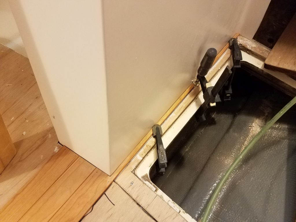
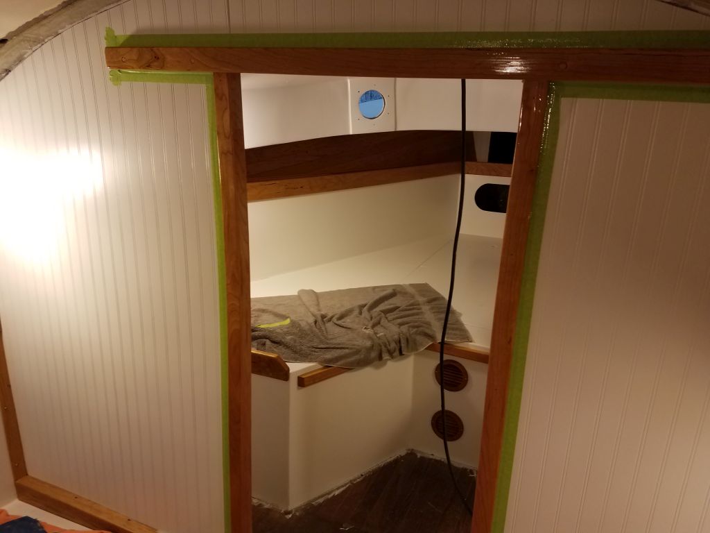
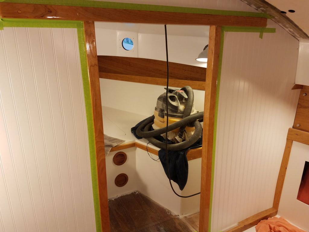
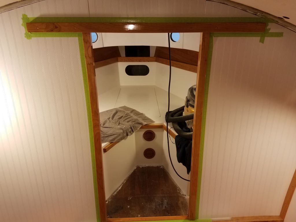
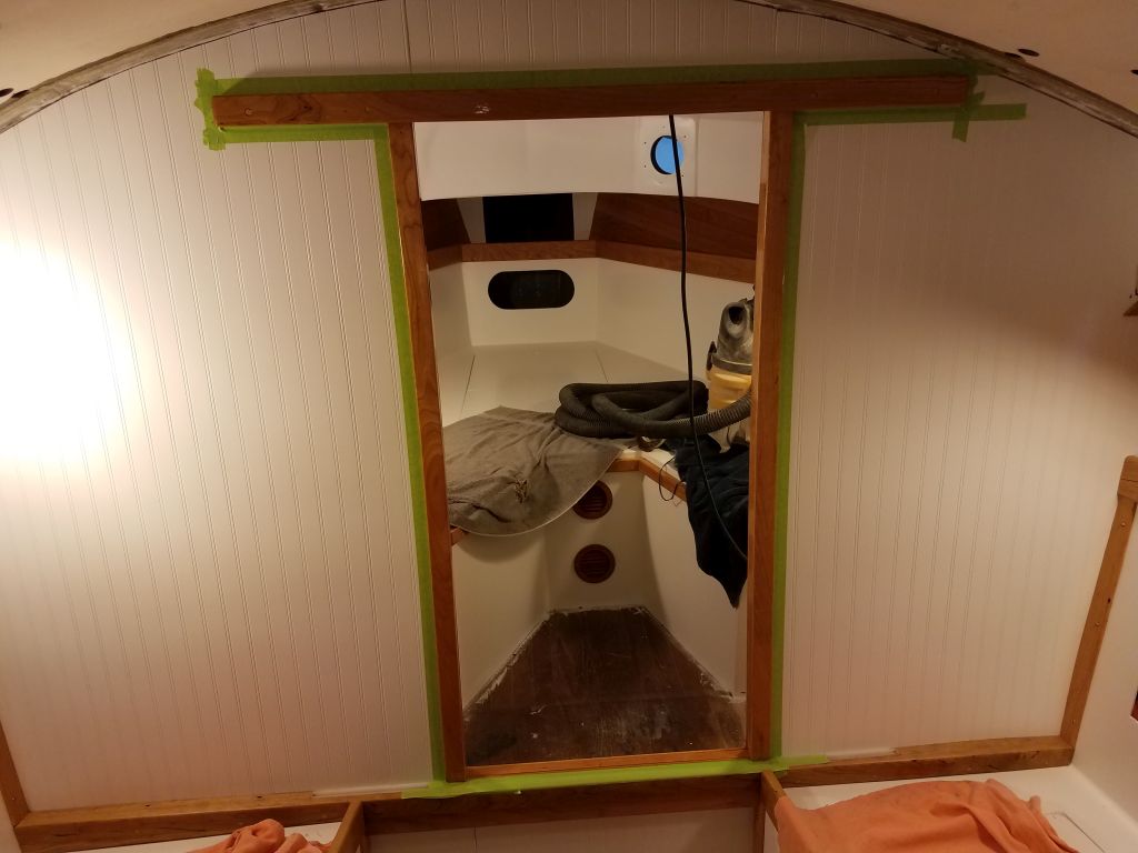
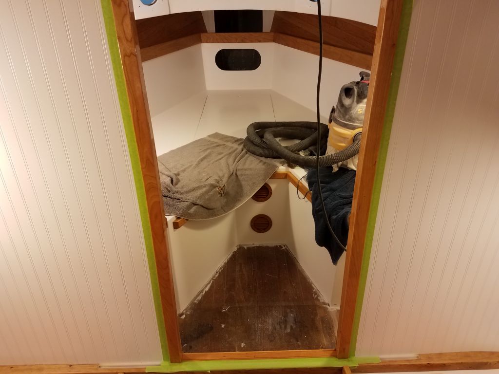
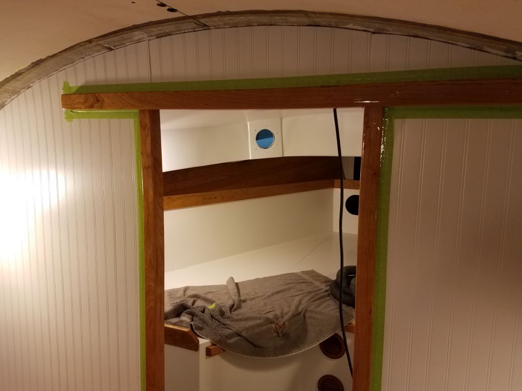
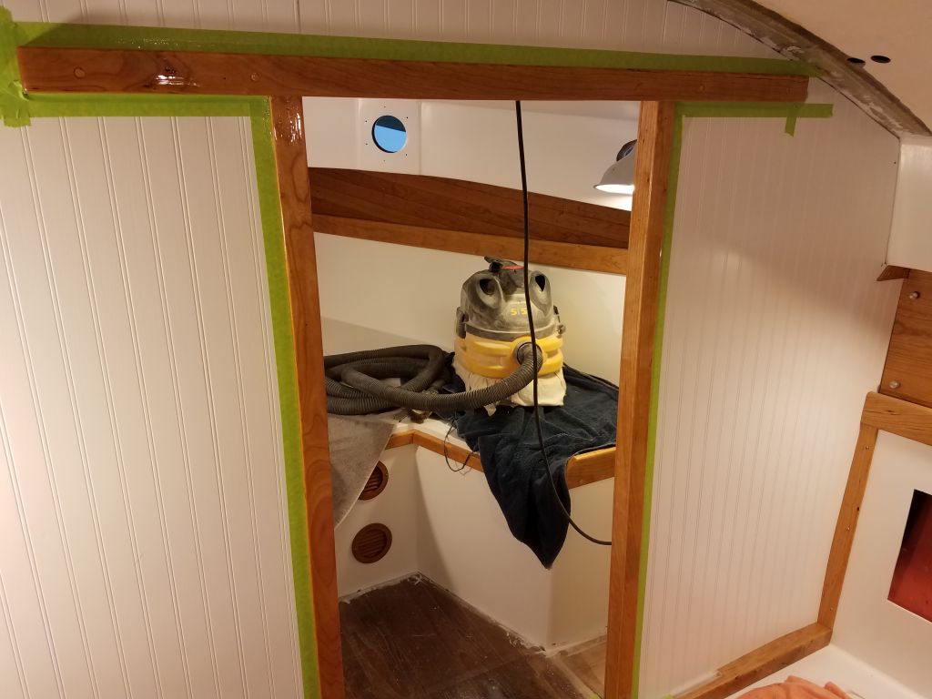
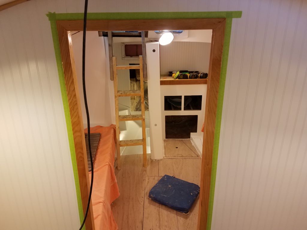
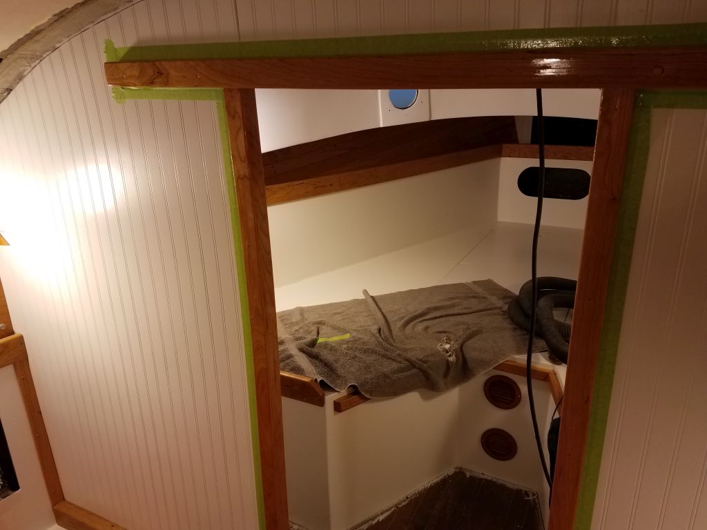
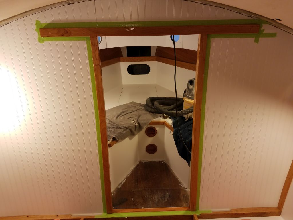
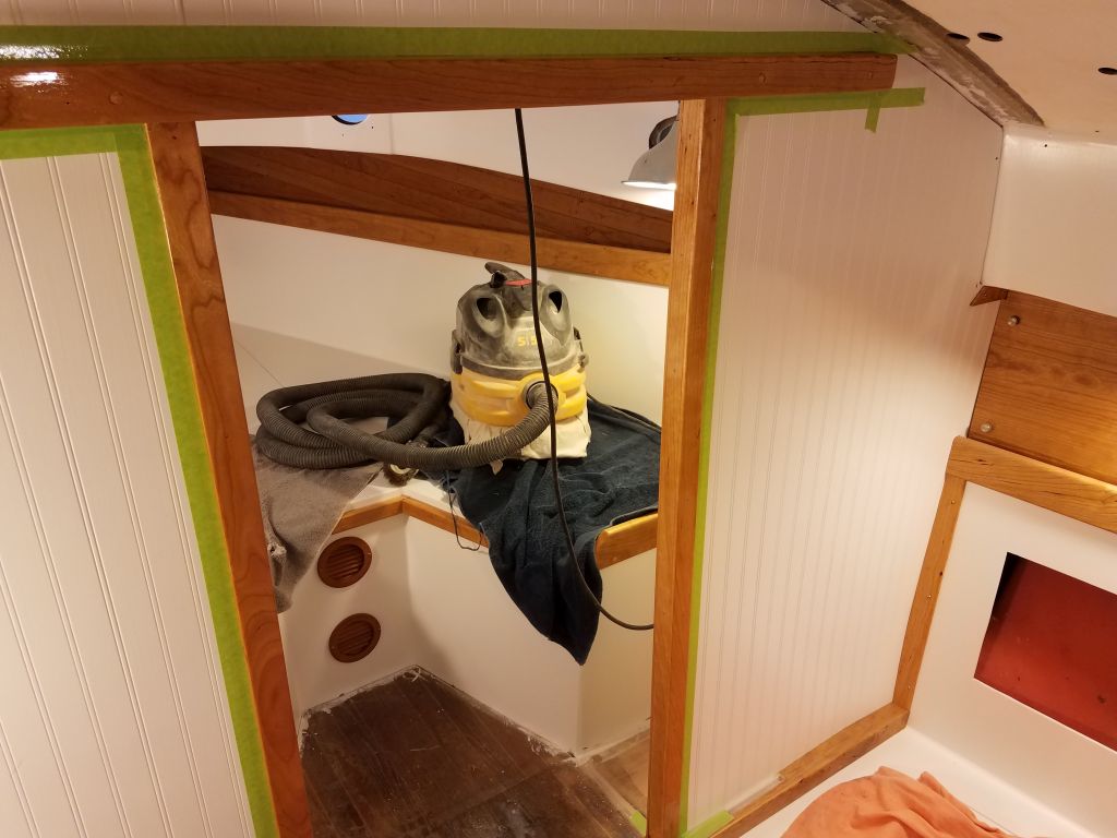
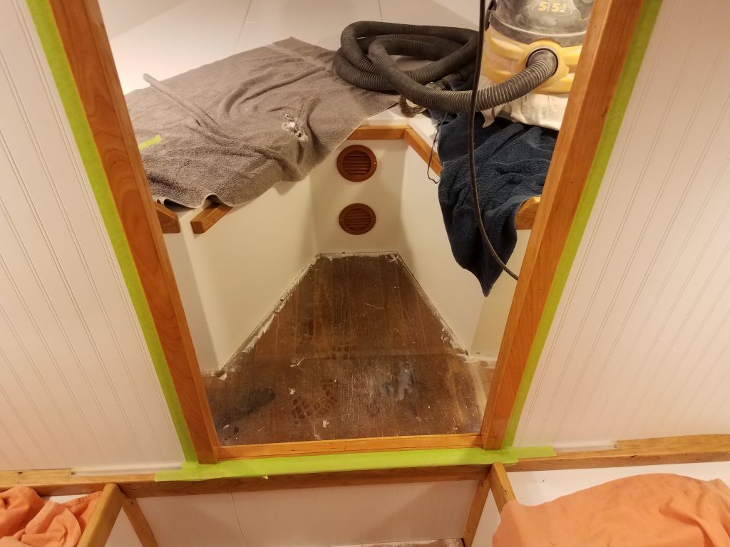
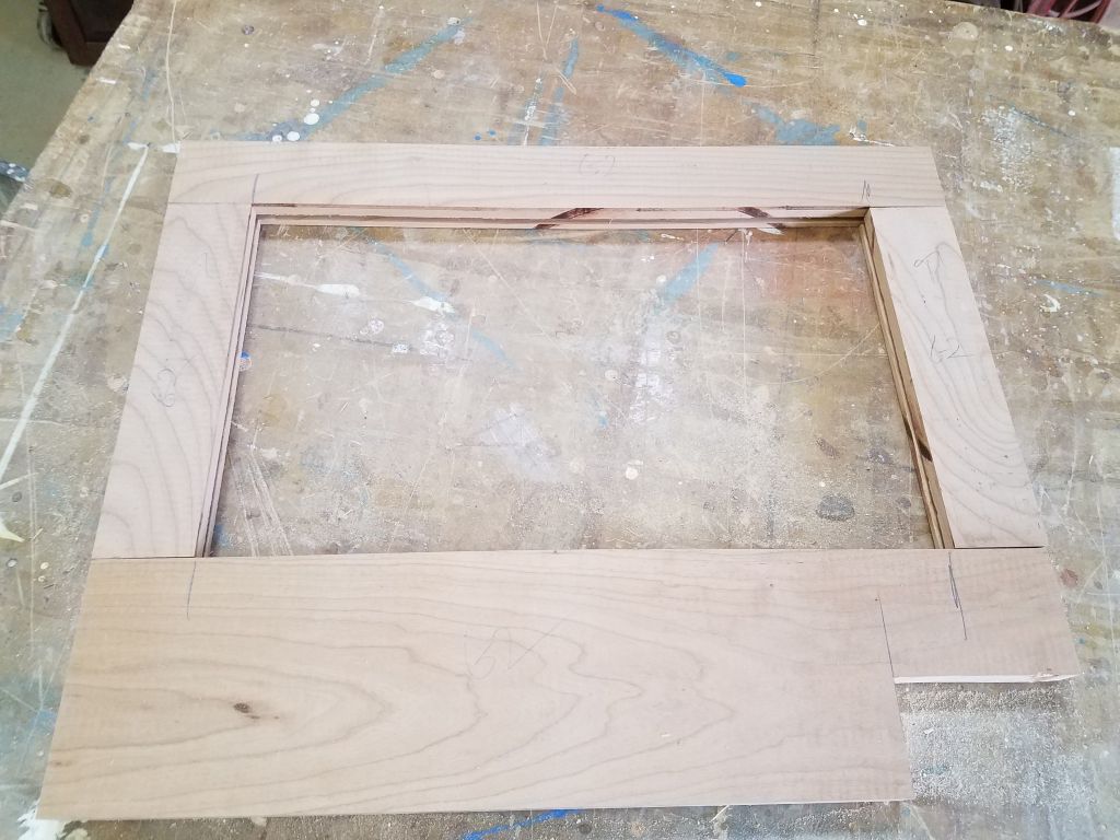
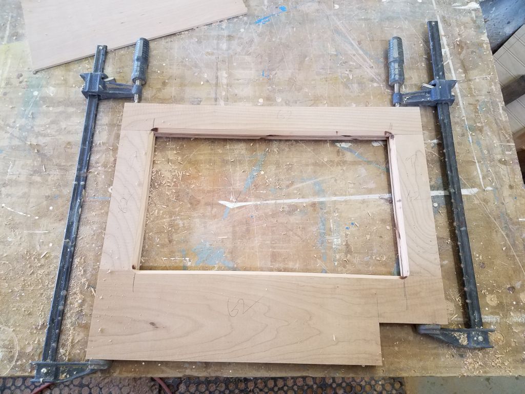
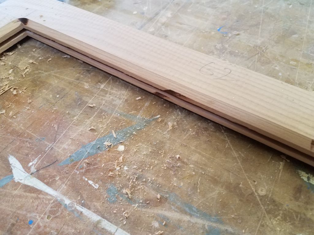
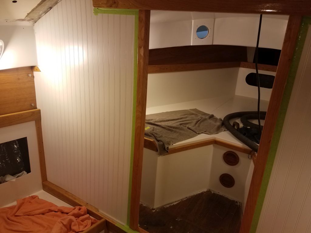
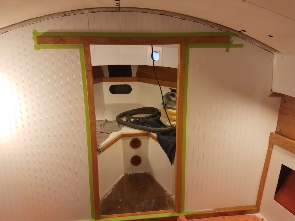
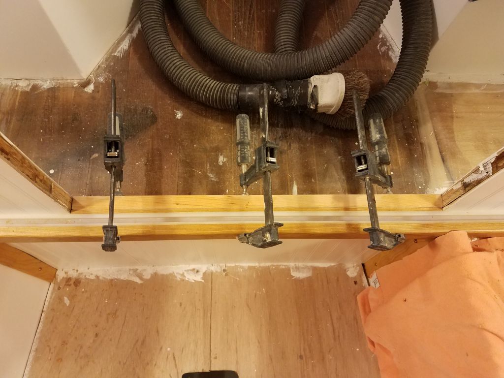
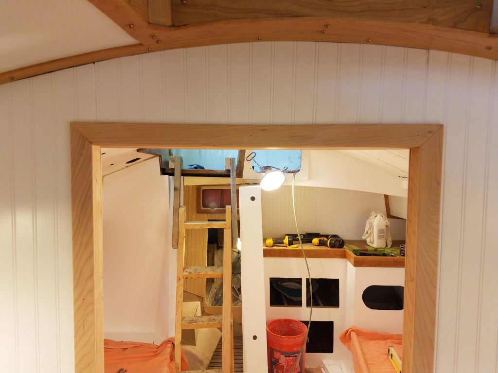
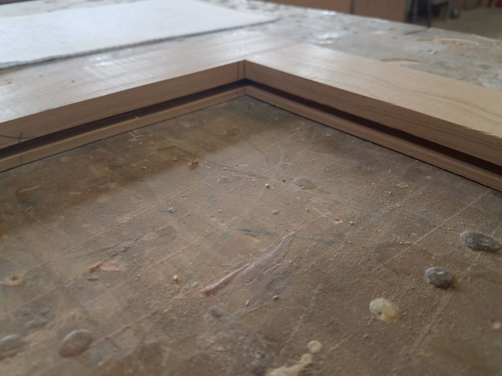
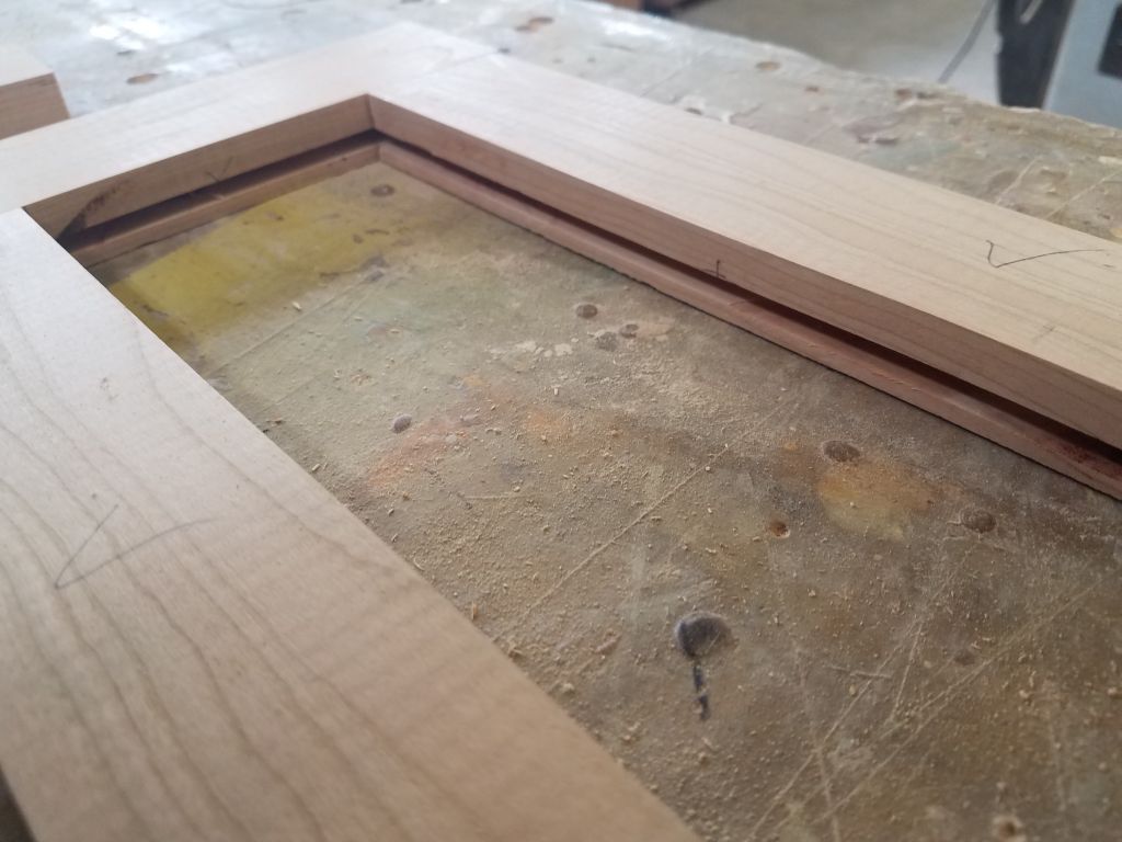
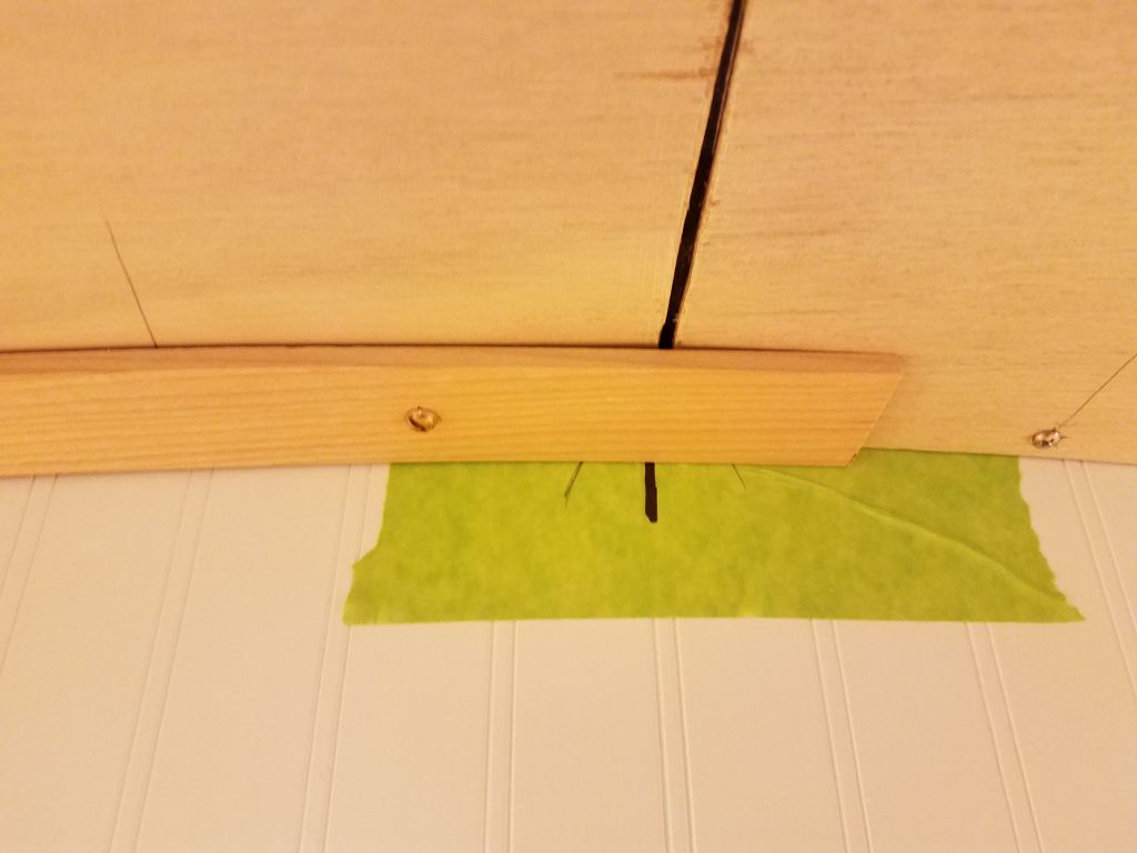
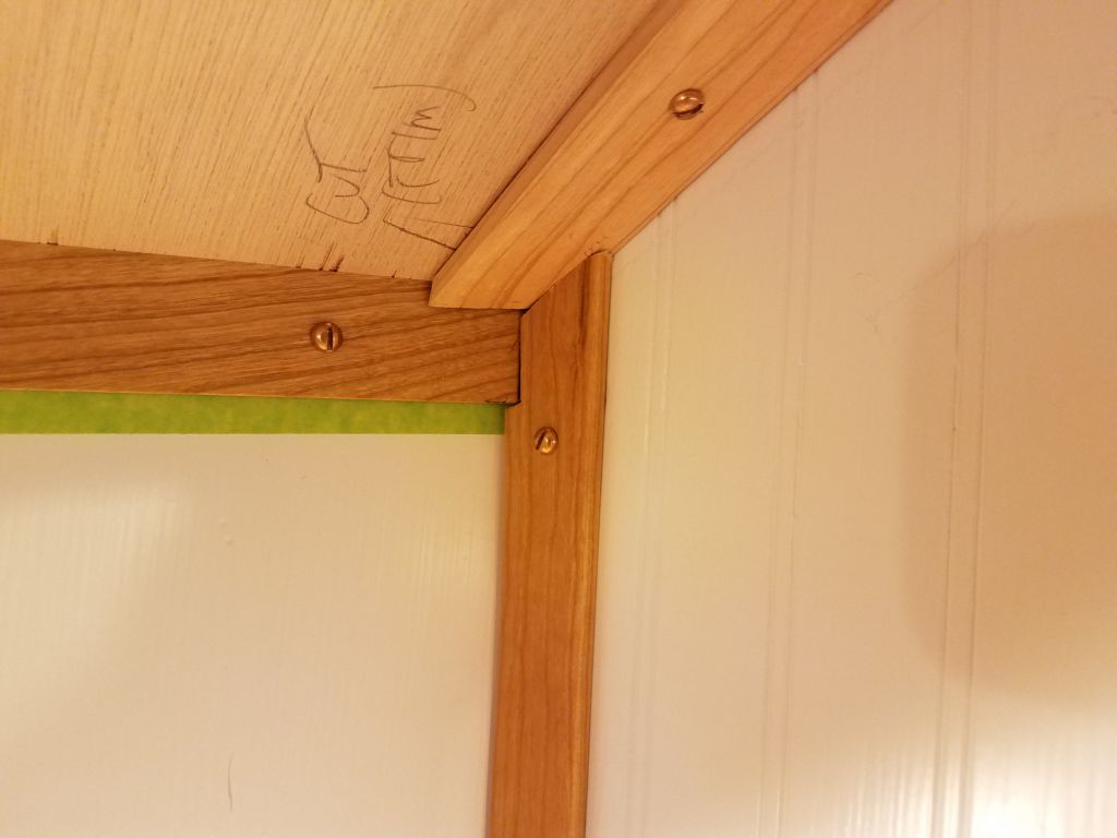
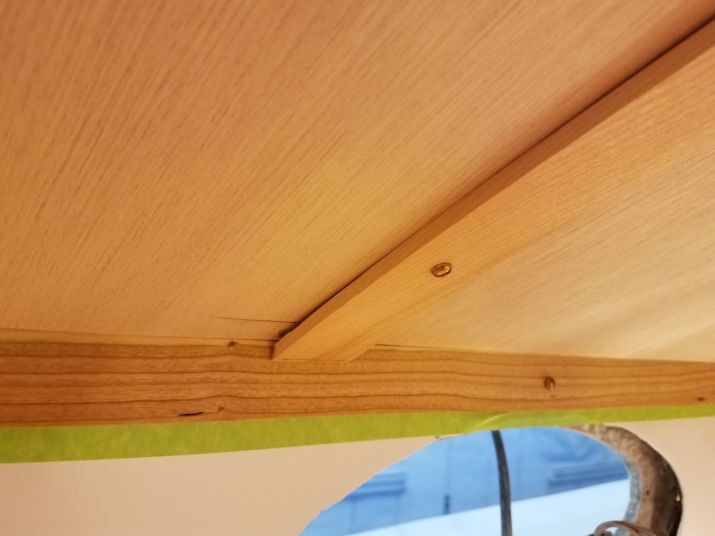
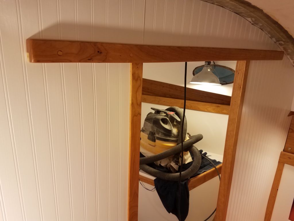
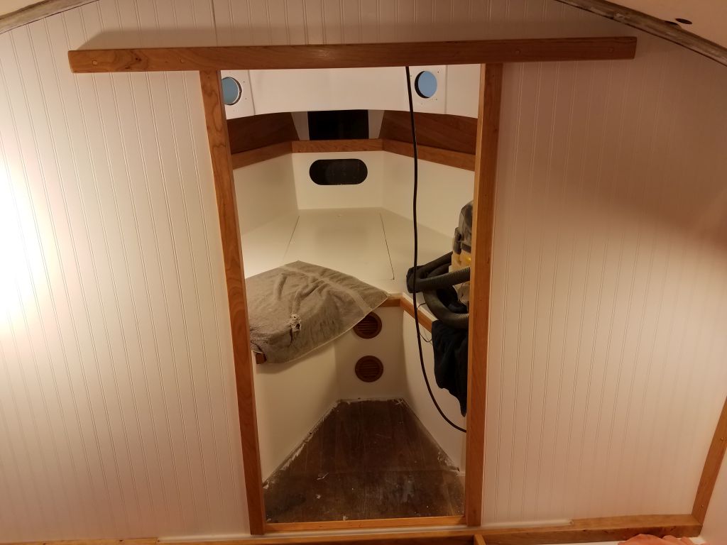
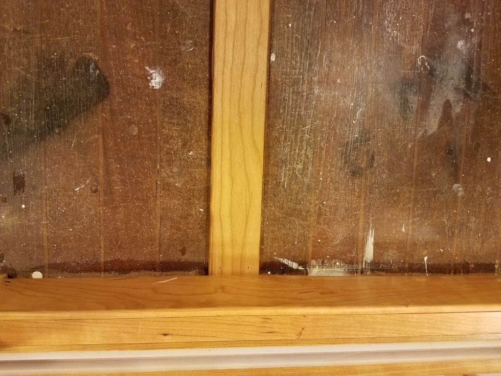
With the varnish on the forward cabin door trim complete, I removed the masking tape.
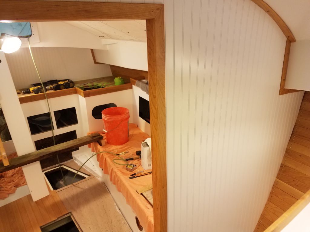

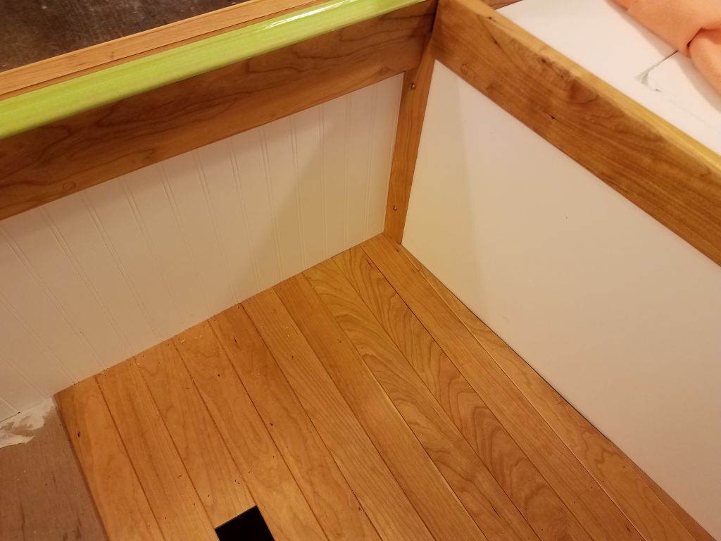
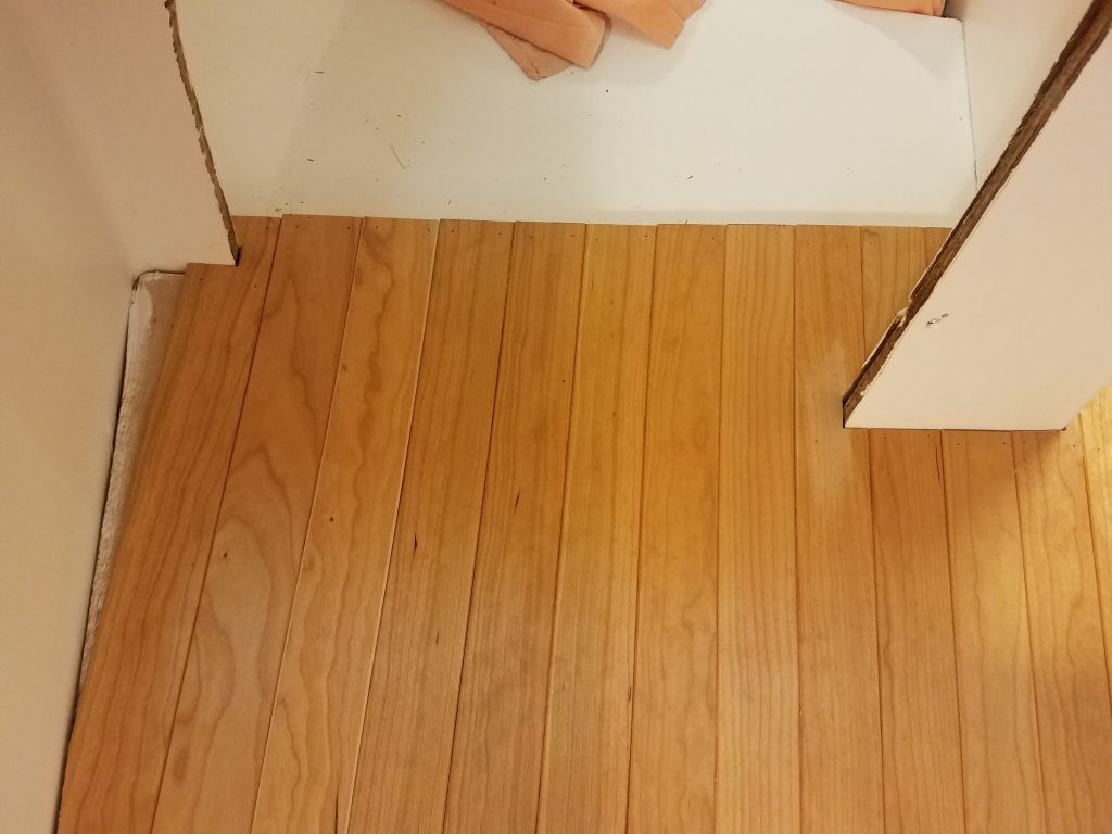
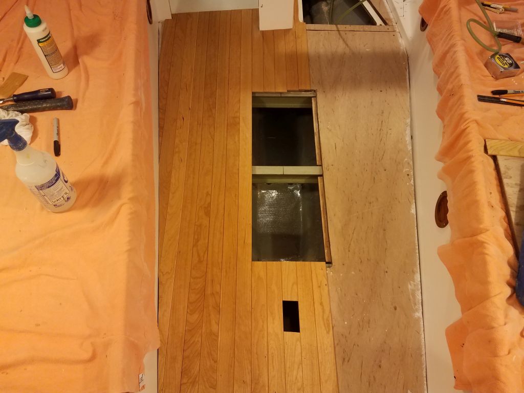
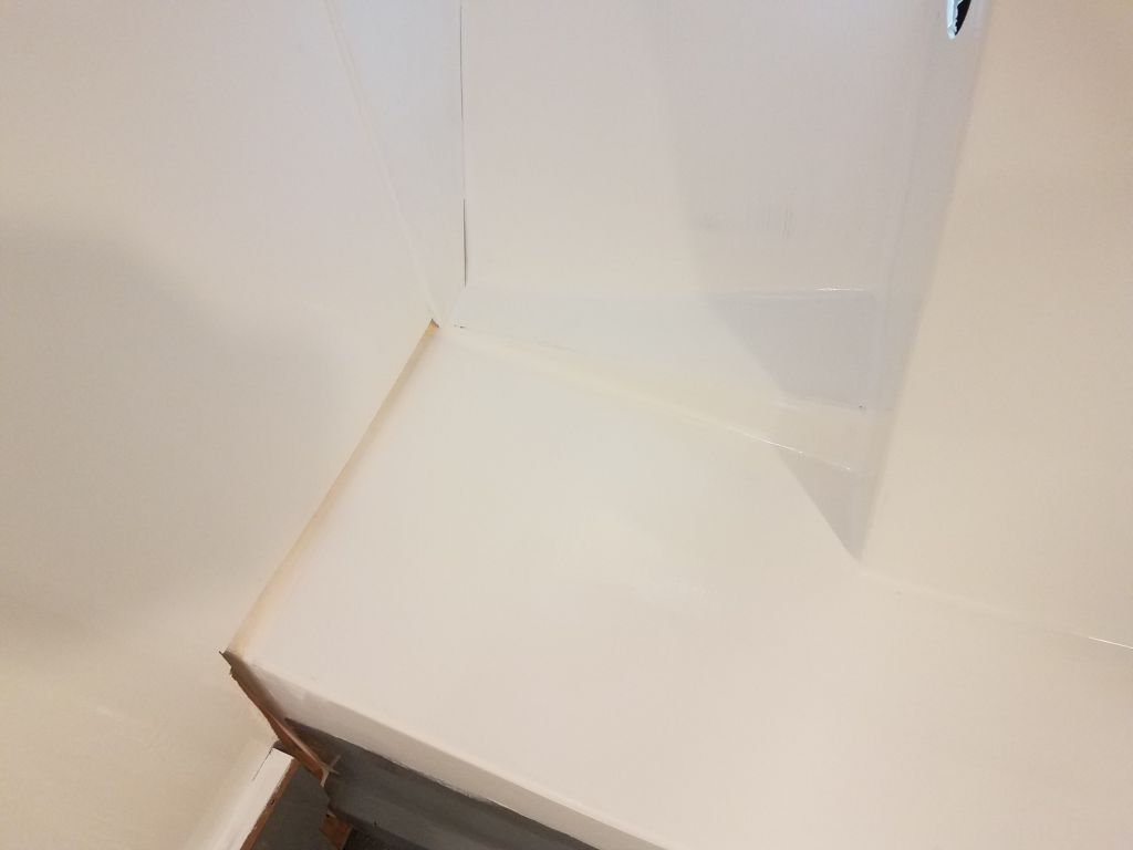
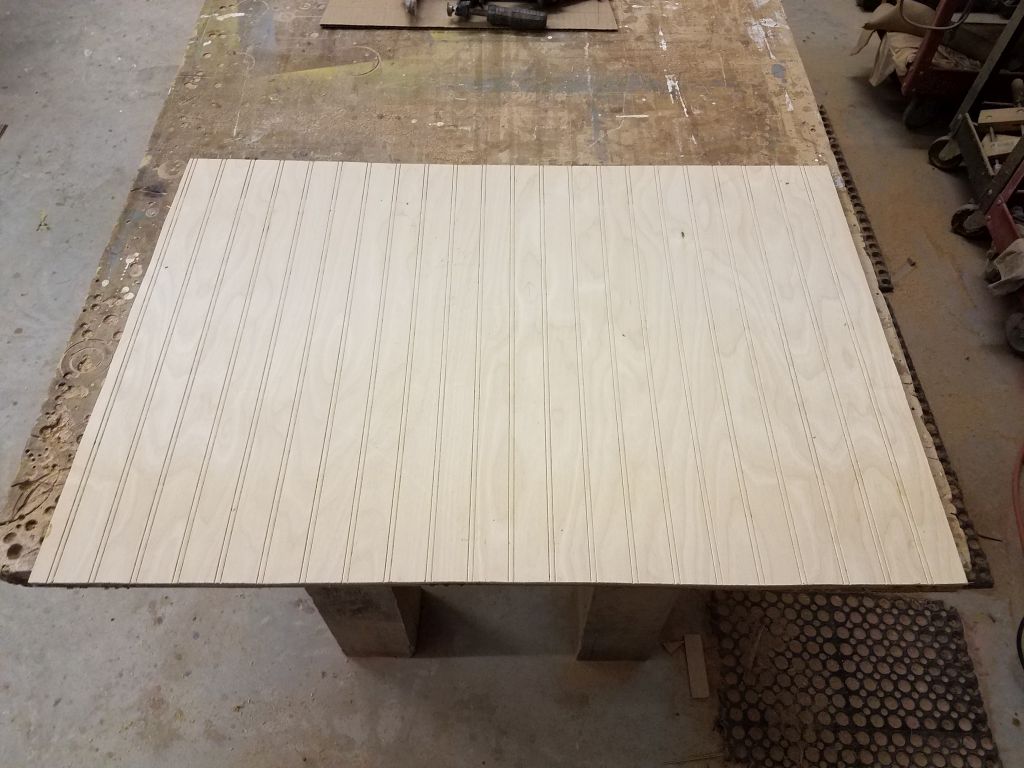
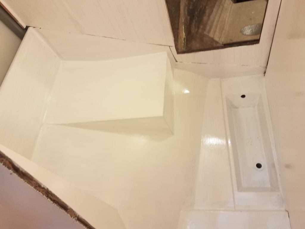
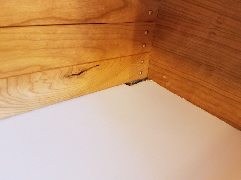
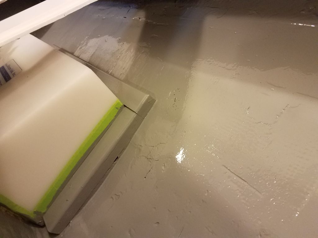
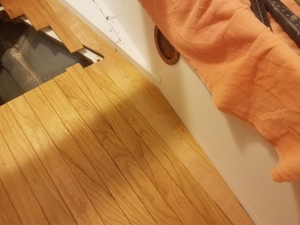
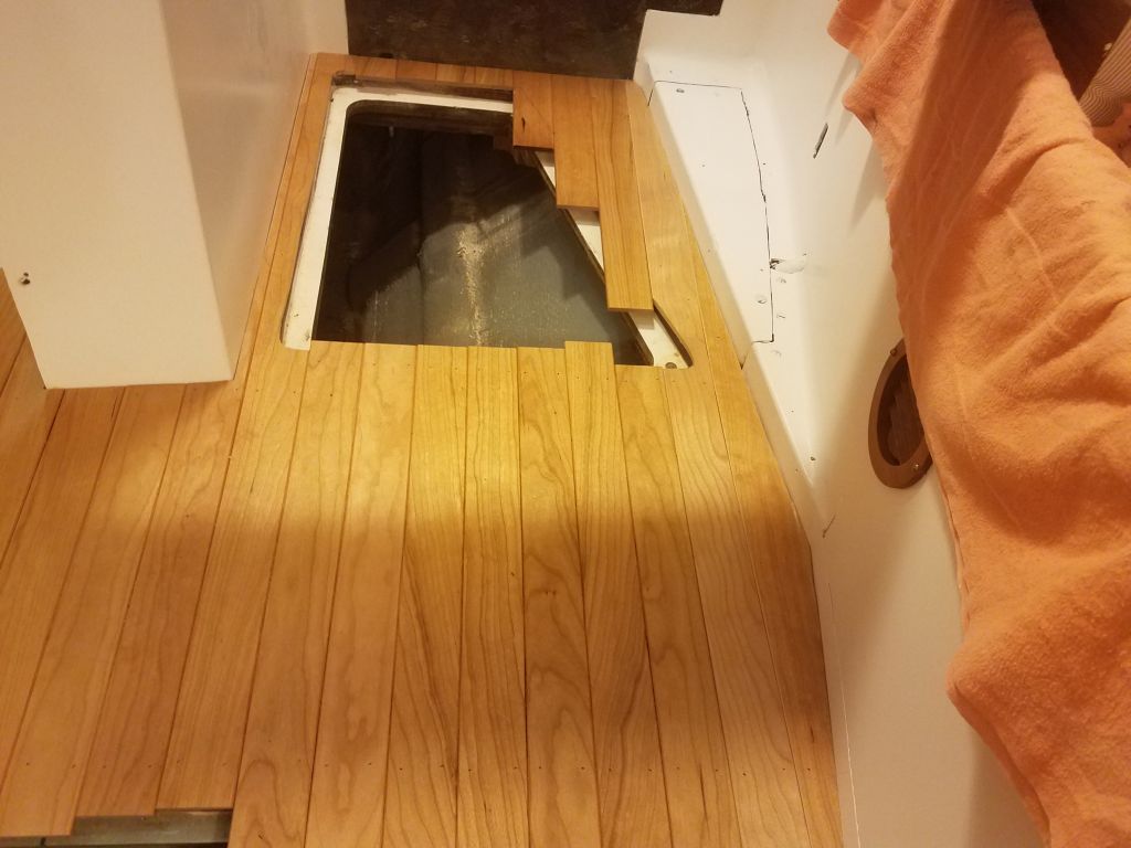
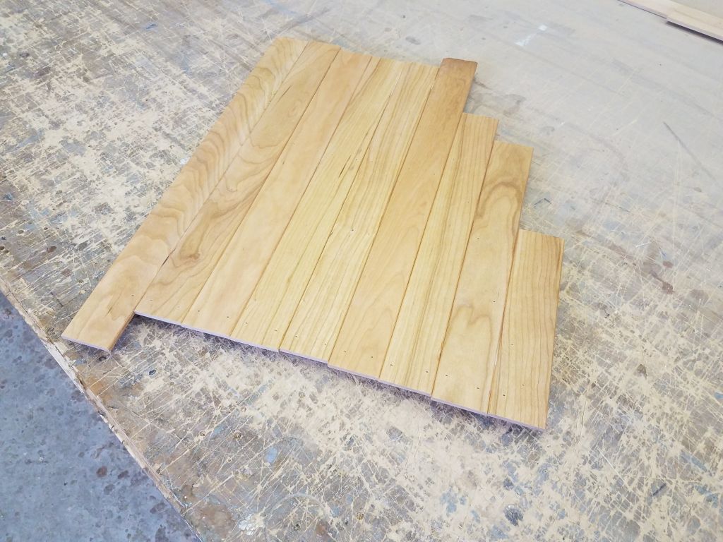
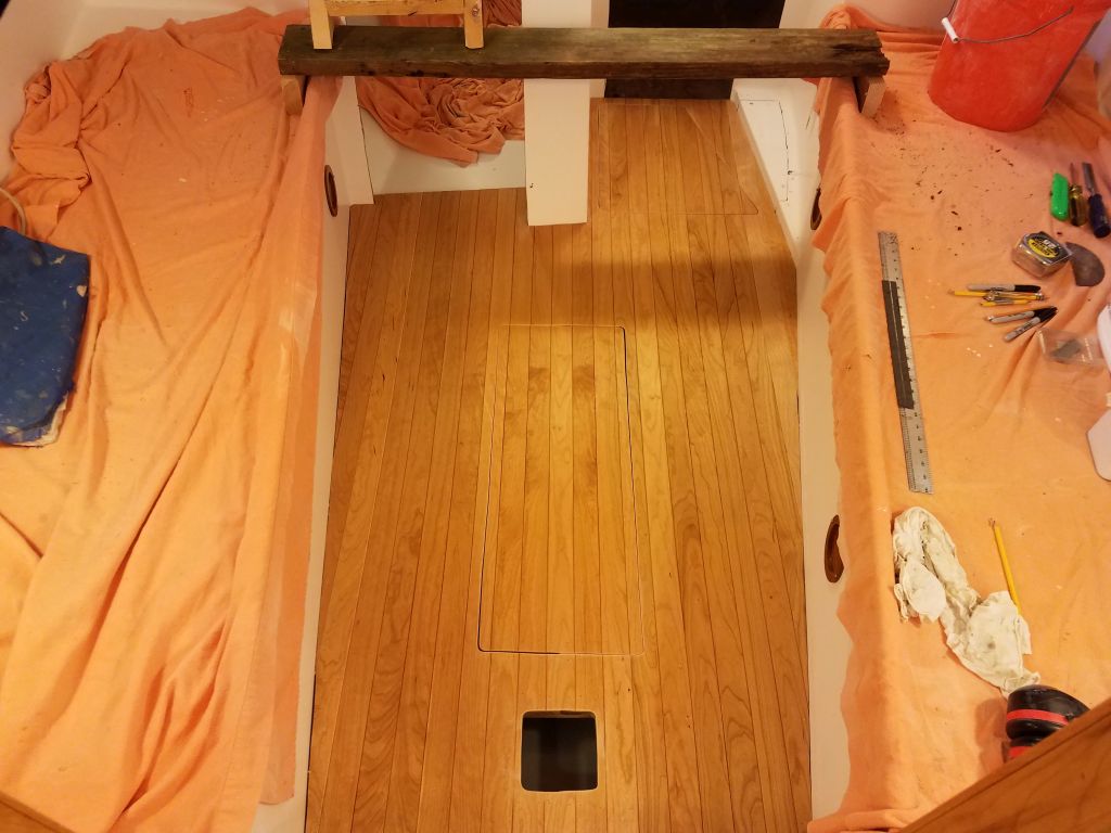
Continuing on the cabin sole, I started with a small piece to fill in the last corner on the starboard side, then continued on the port side with four or five long boards to fill in the bulk of the remaining space. As before, I cut lengths for the galley hatch and the tiny area aft of it from the same lengths of board at the same time to keep the grains consistent, and secured the planks with glue and brads. Once I passed the forward corner, each board required long angle cuts on the ends to fit; the next-to-last piece fitted here required careful cuts at both ends, and a fair bit of final fitting before it was right.
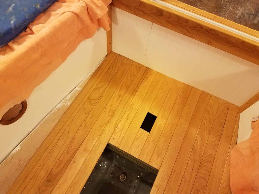
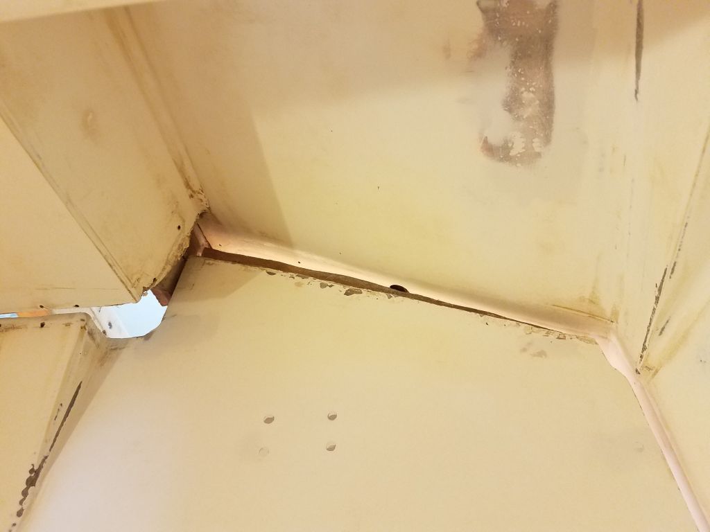
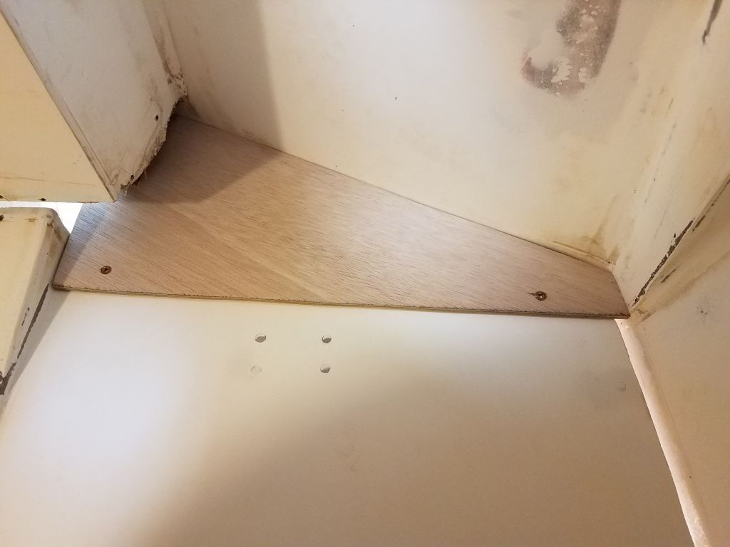
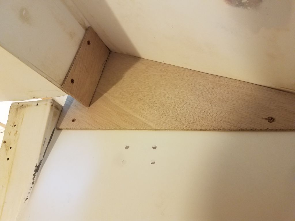
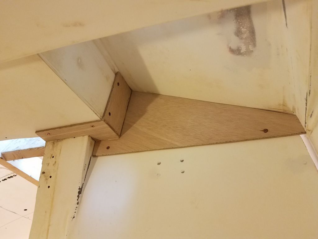
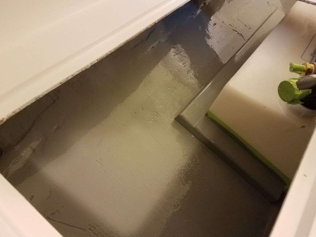
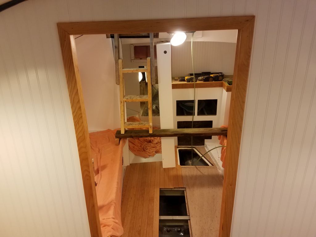
This left a small triangular section that required a pattern and some test-fitting before I achieved the final fit and completed the main part of the cabin sole.

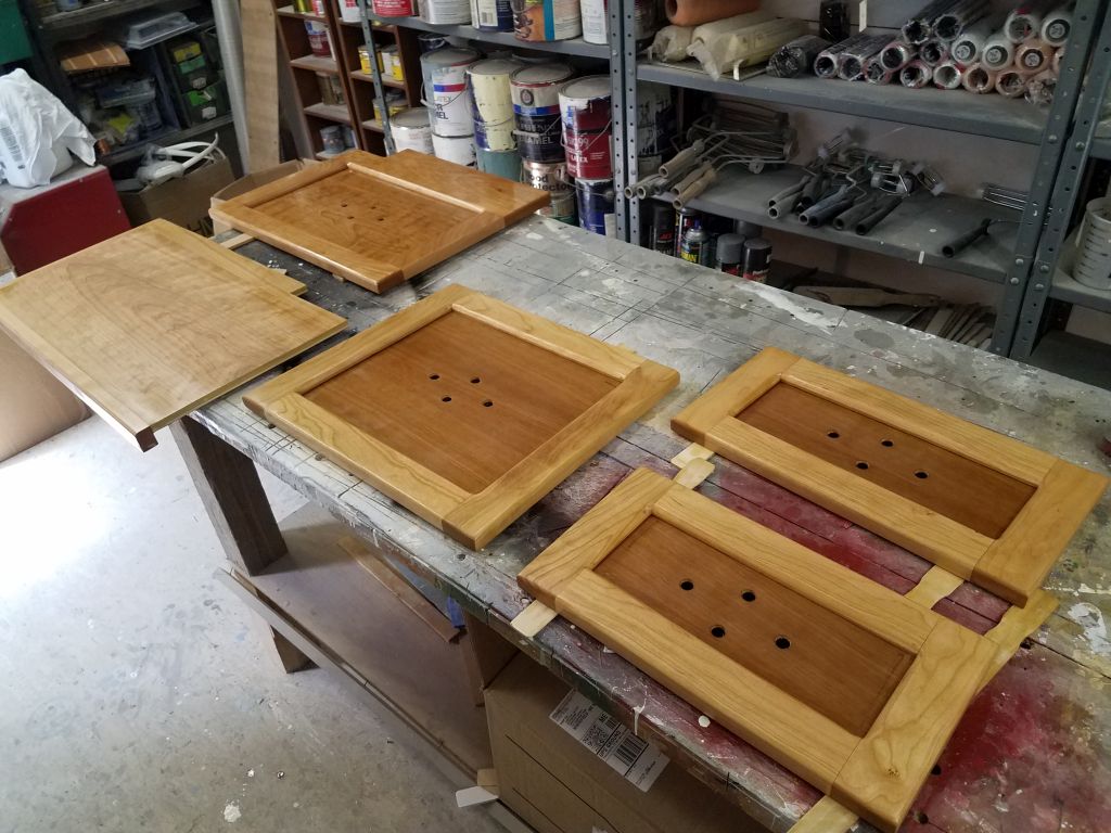
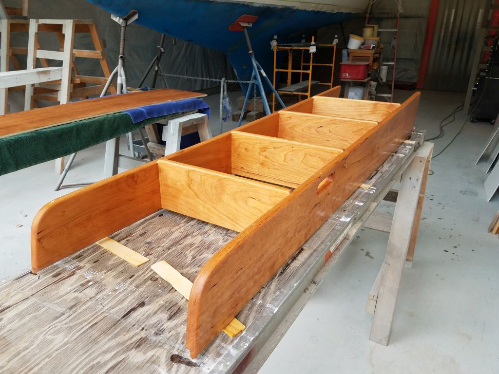
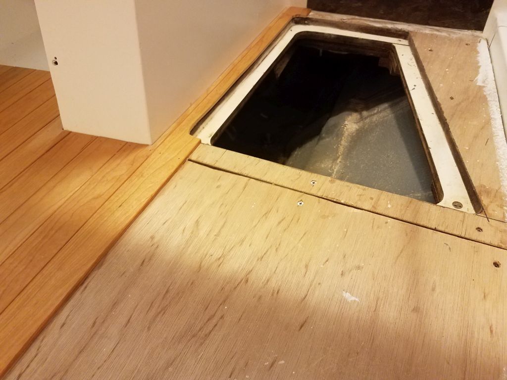
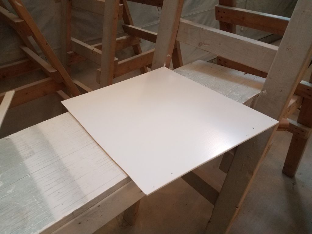
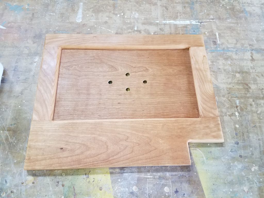
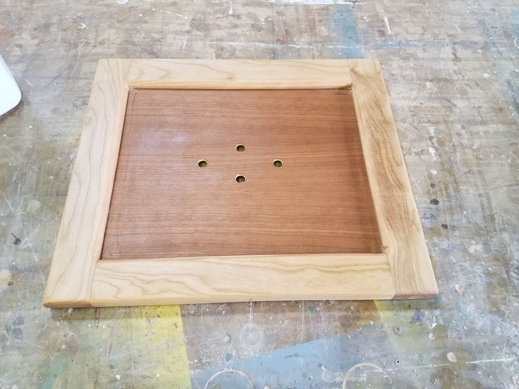
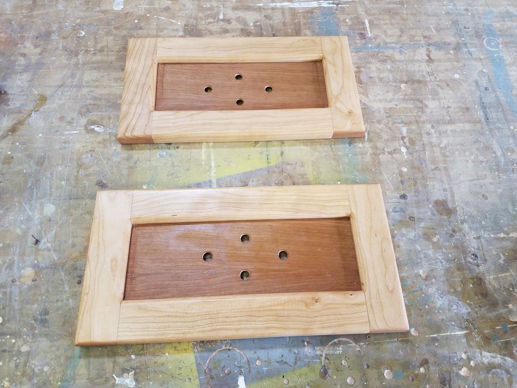
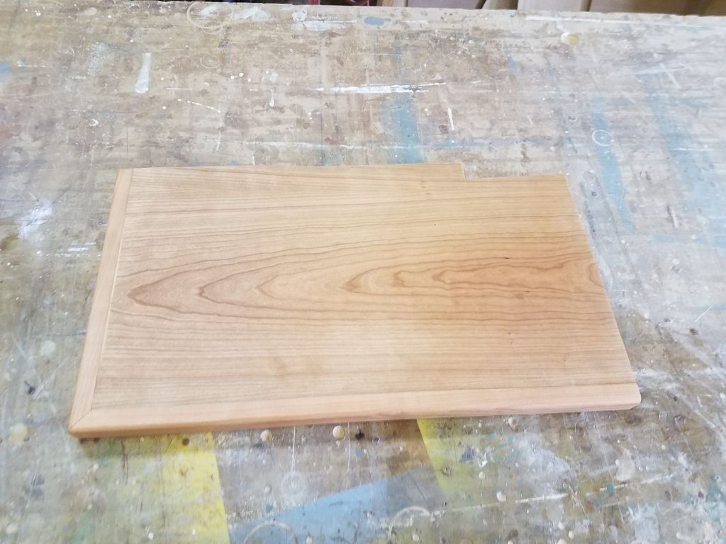
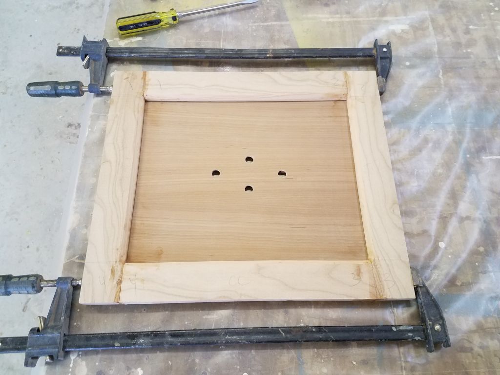
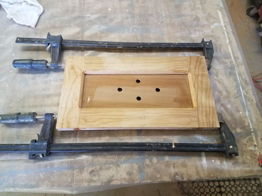
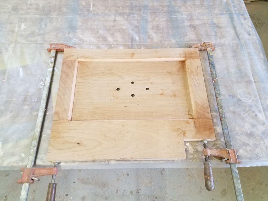
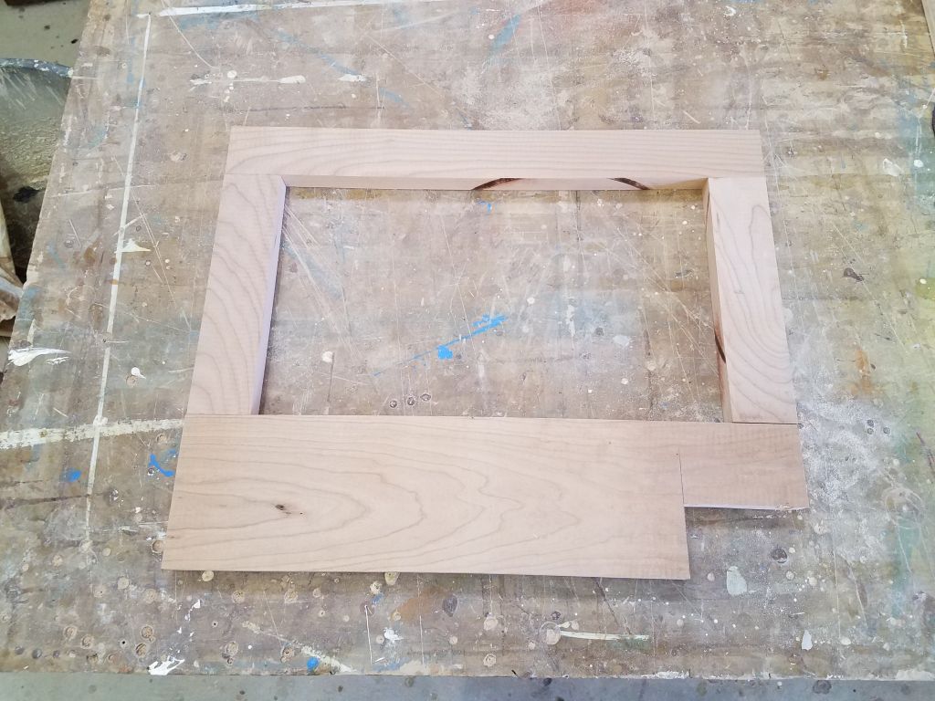
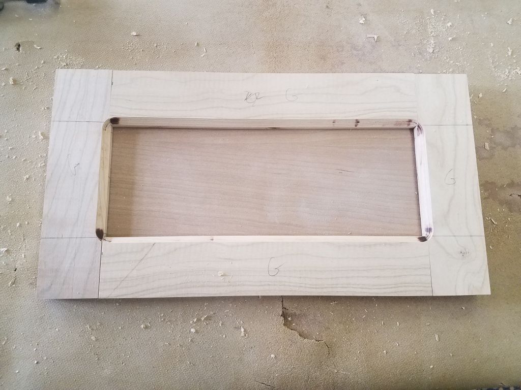
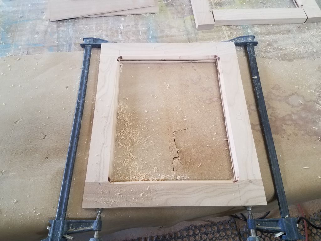
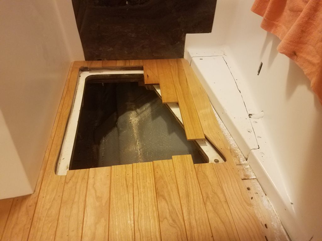
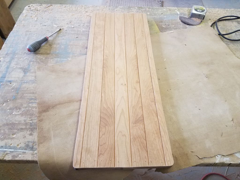
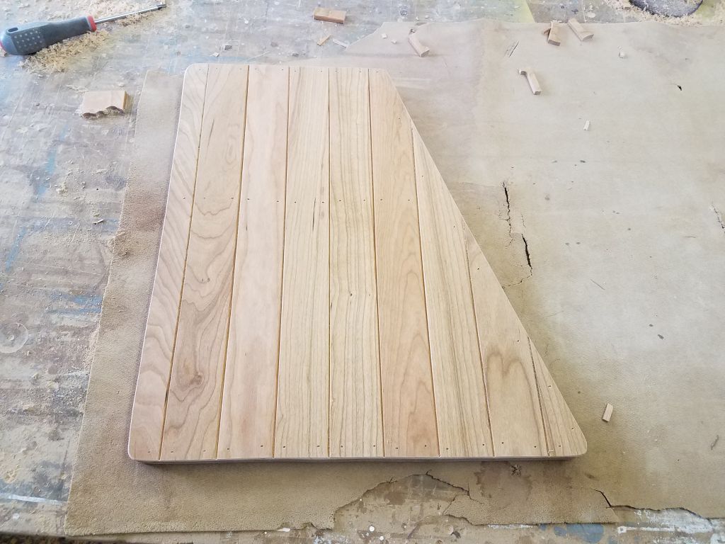
I’d collected the small pieces for the galley hatch down in the shop, and to finish things up now I glued and nailed these to the hatch cover itself.
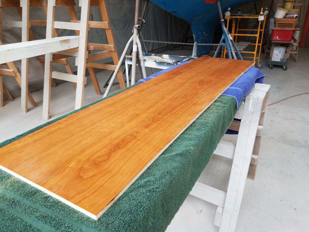
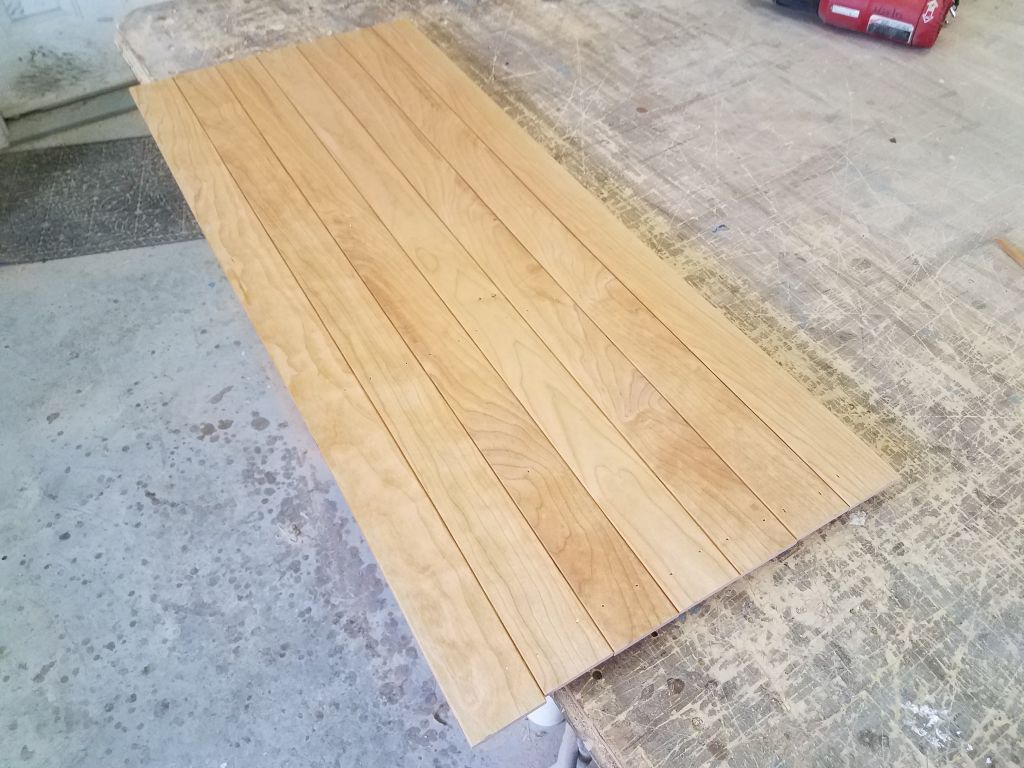
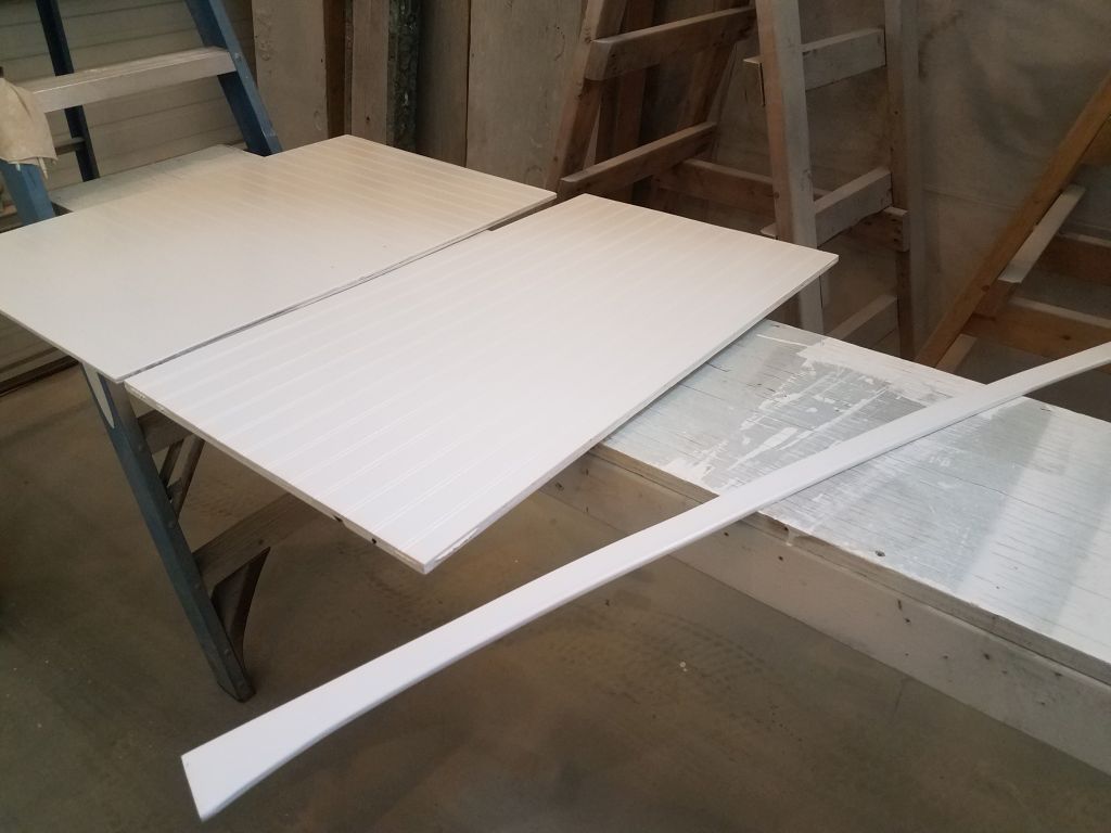
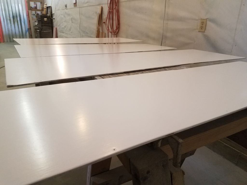
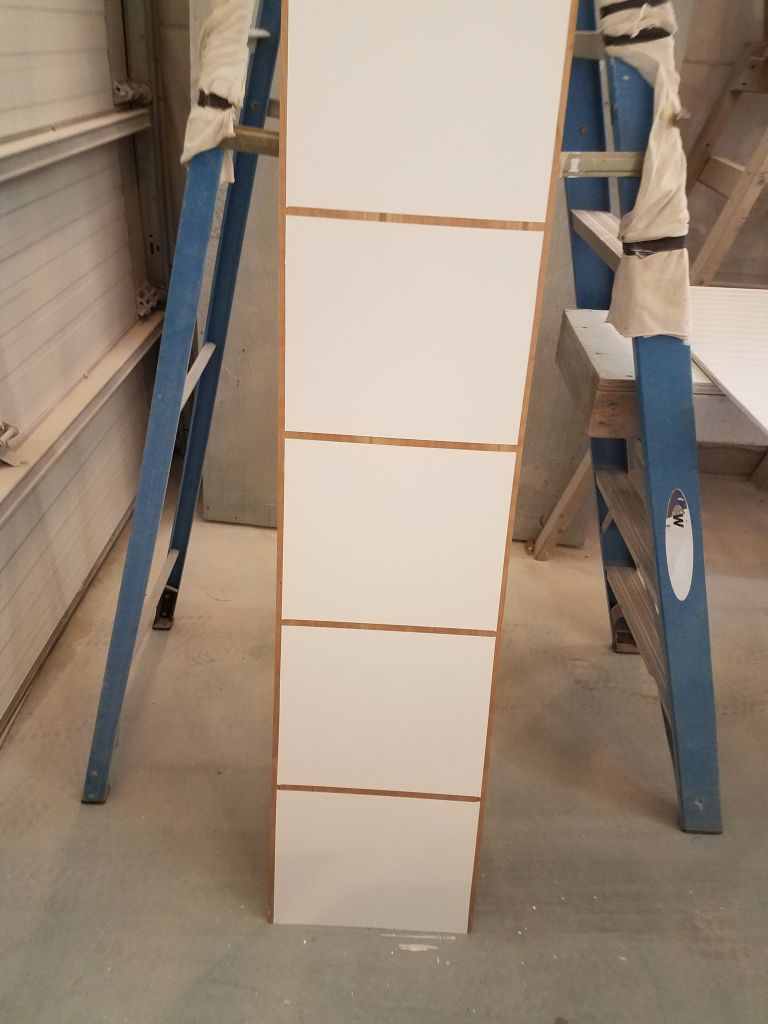
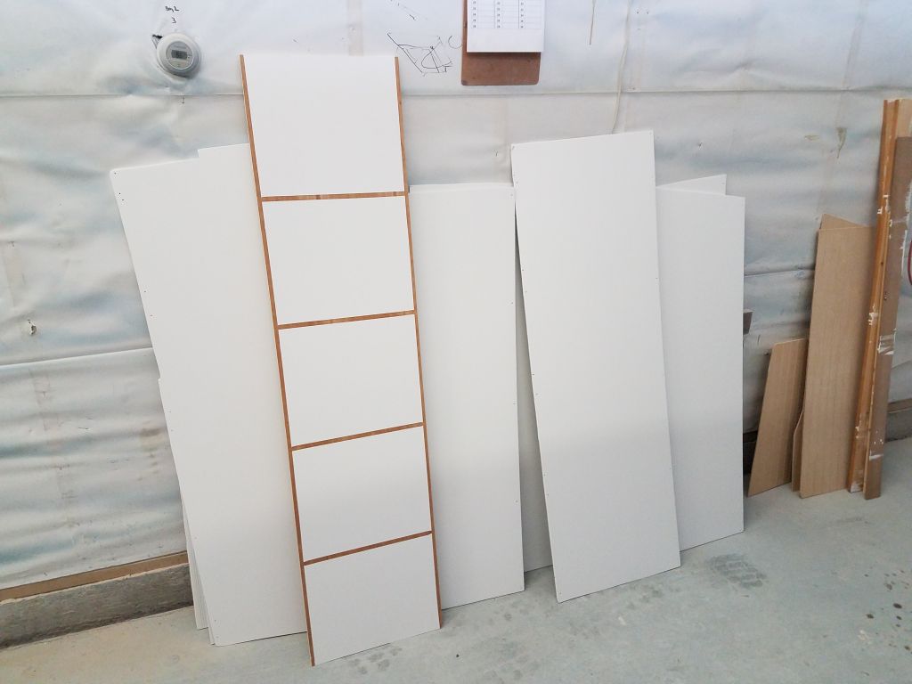
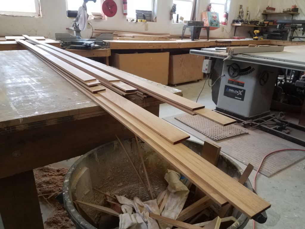
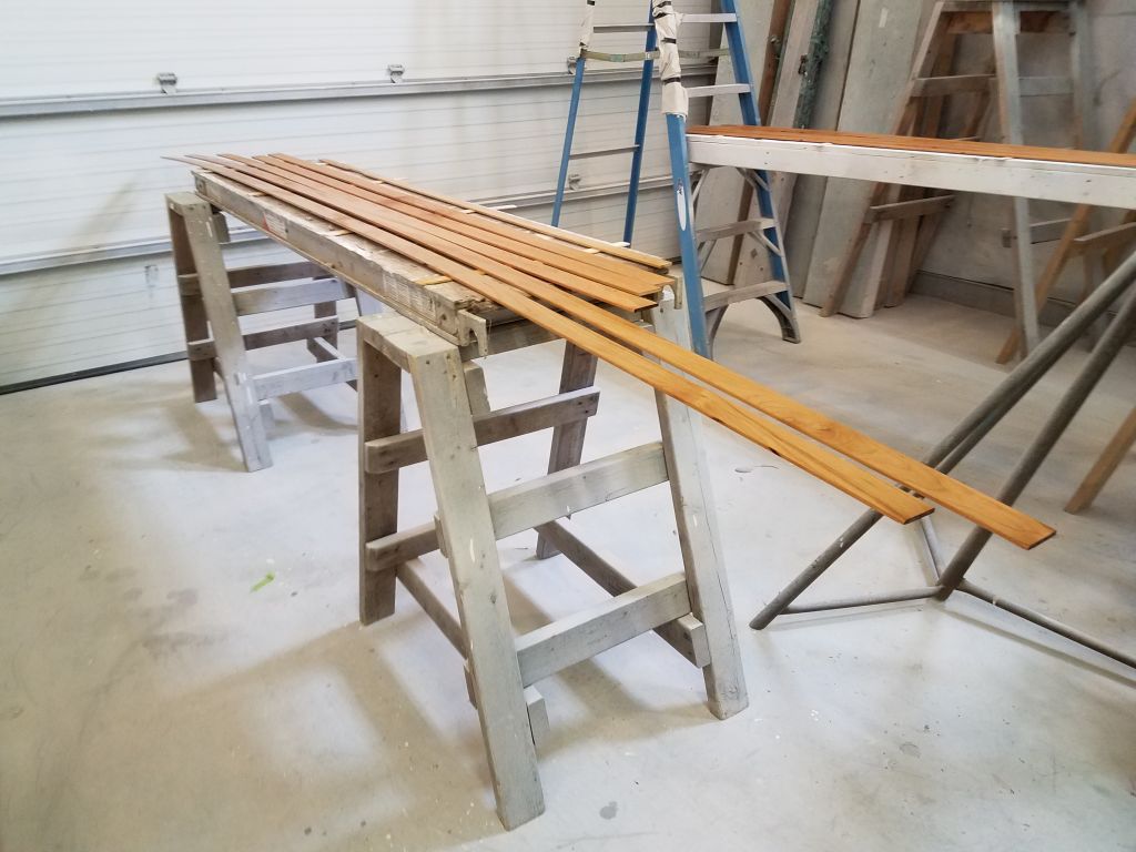
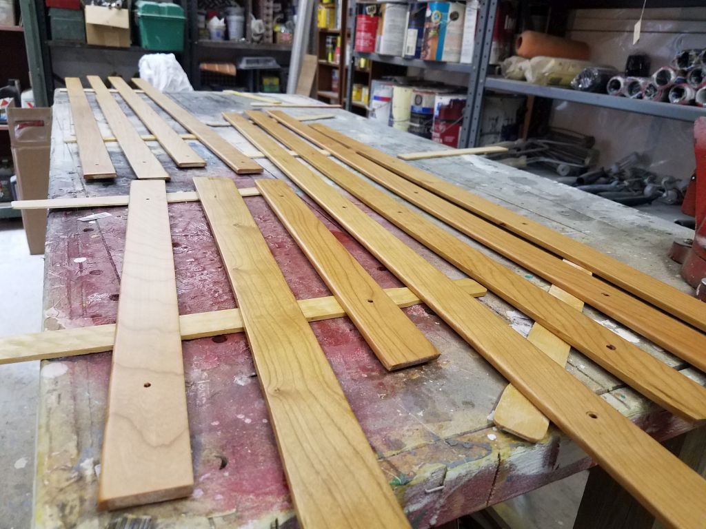
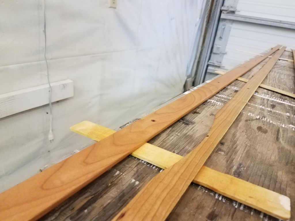
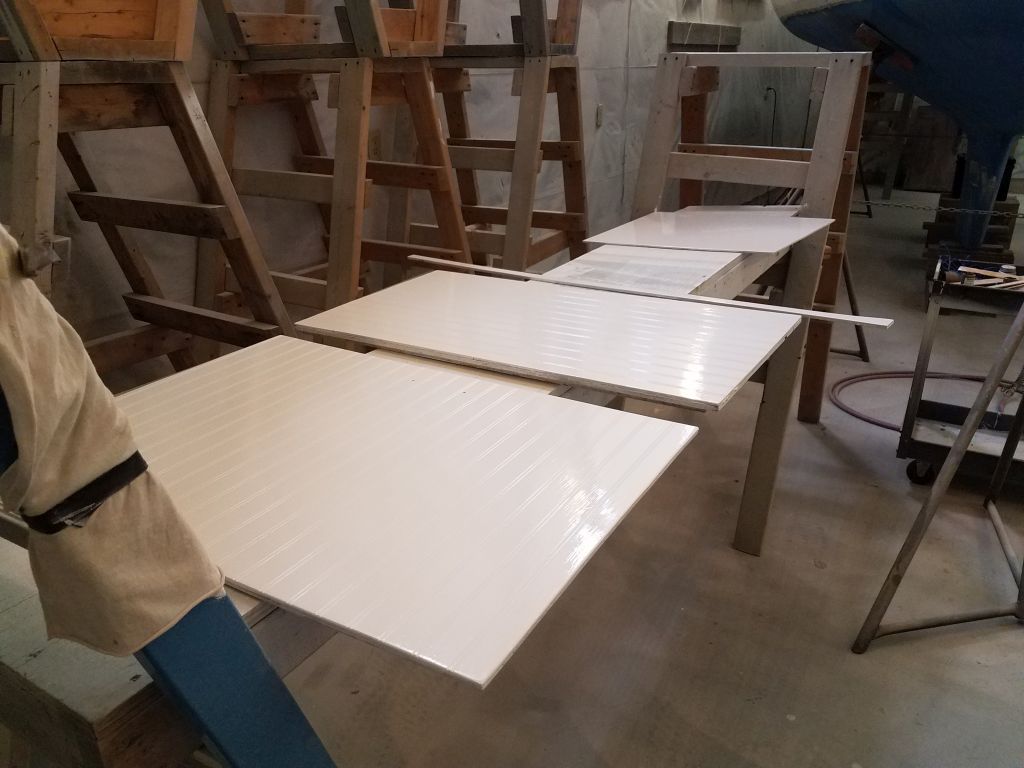
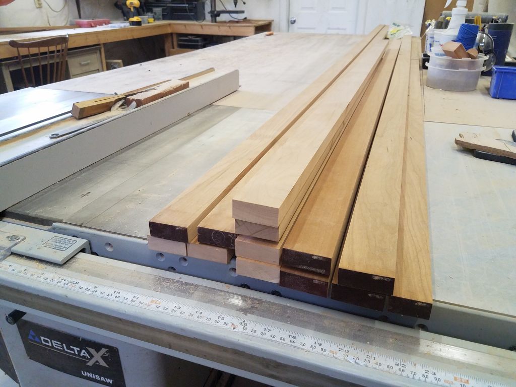
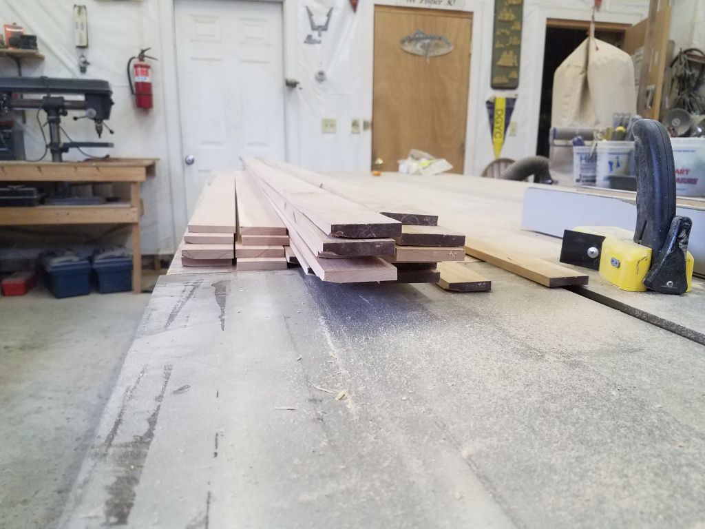
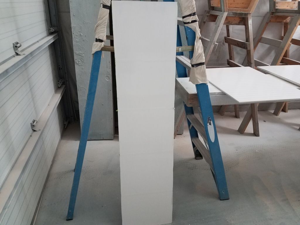
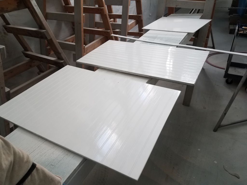
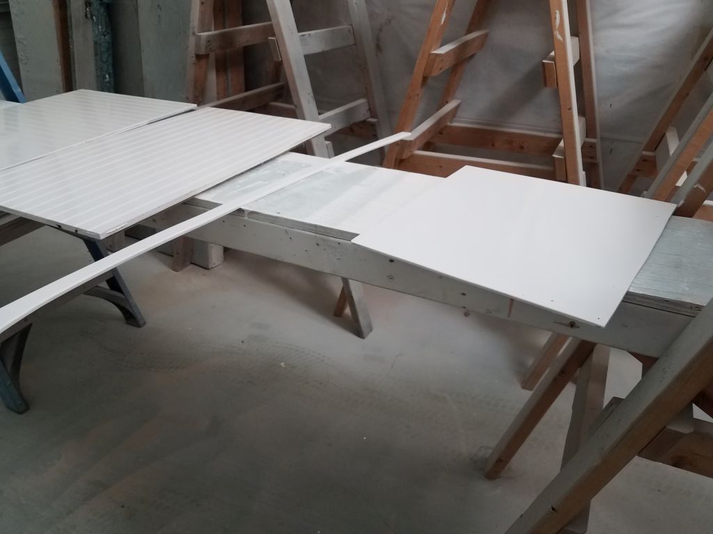
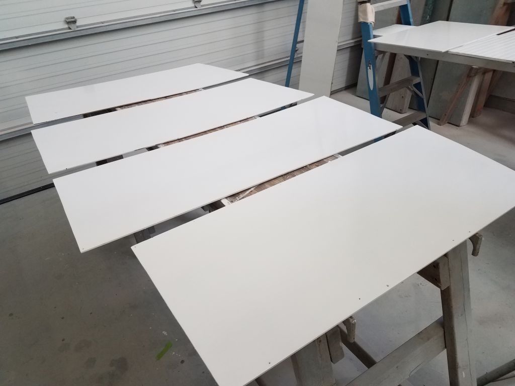
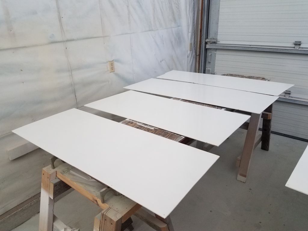
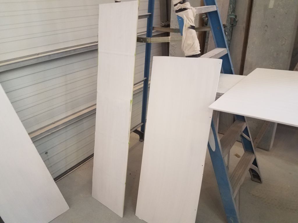
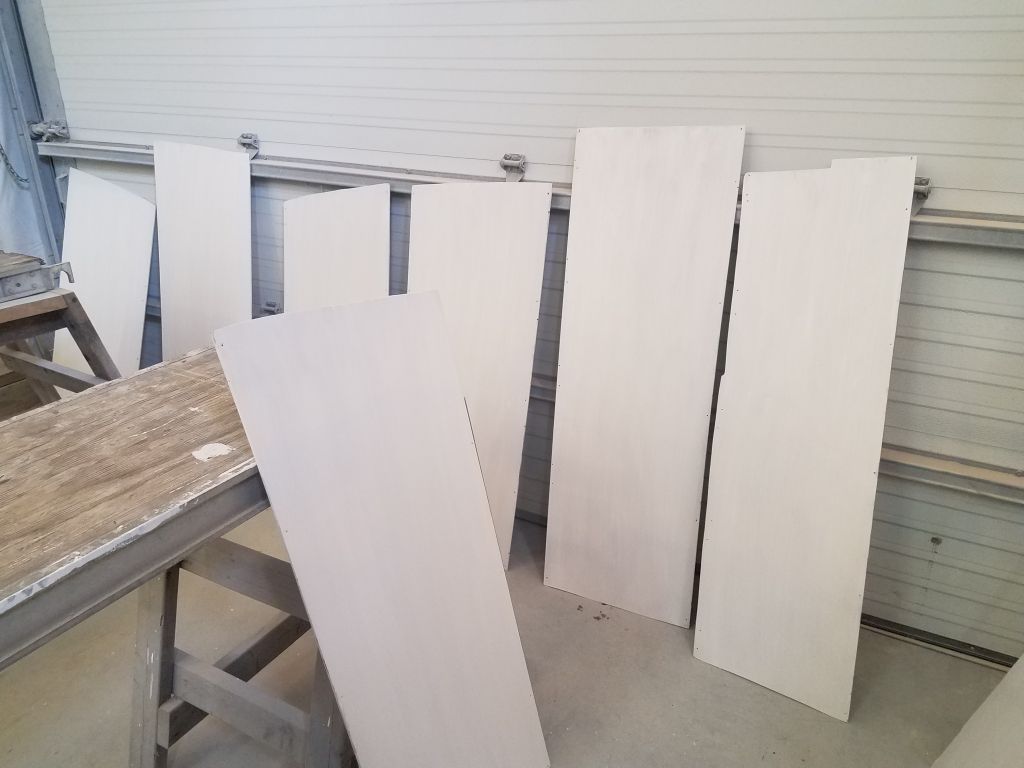
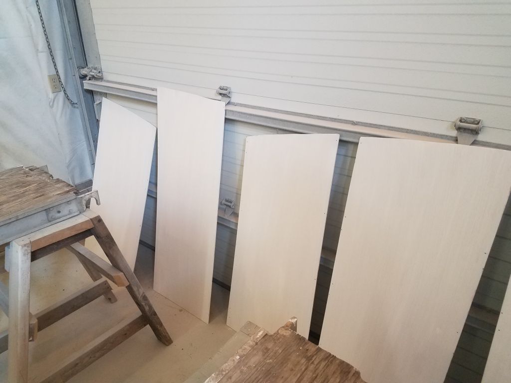
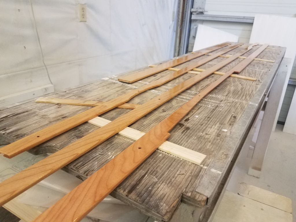
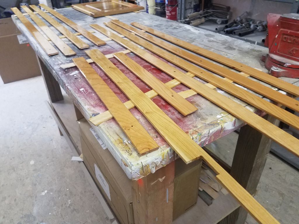
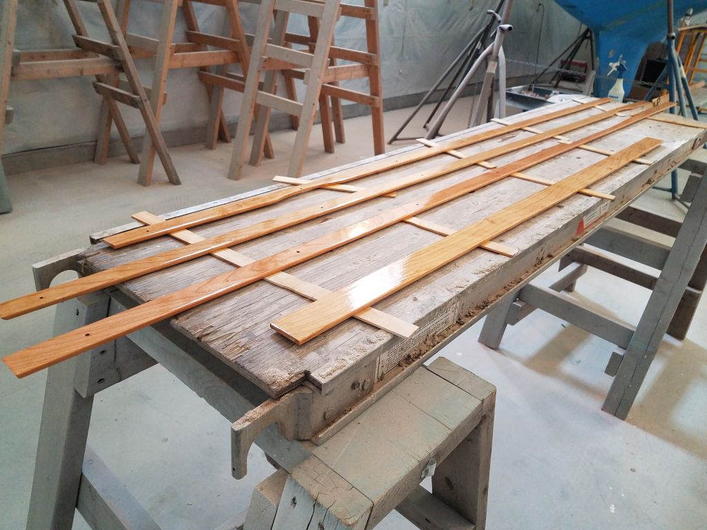
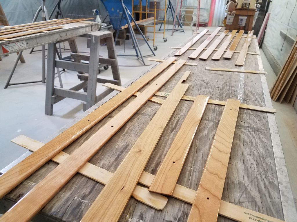
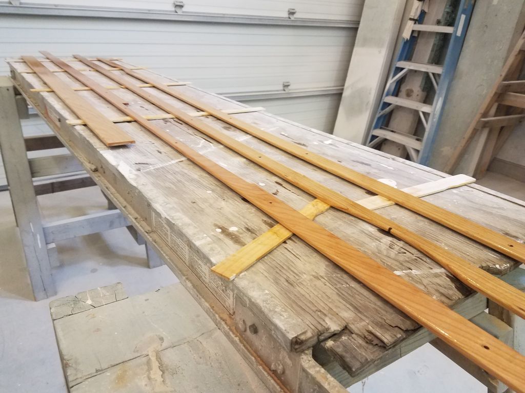
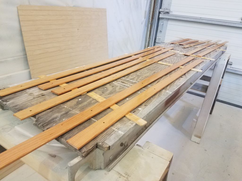
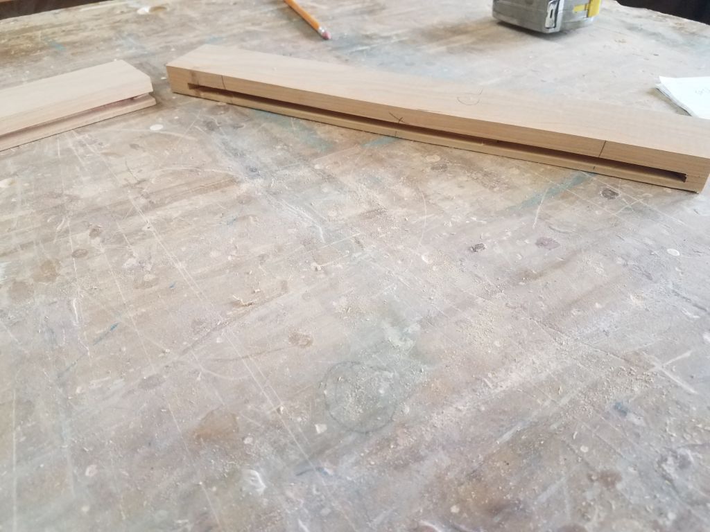
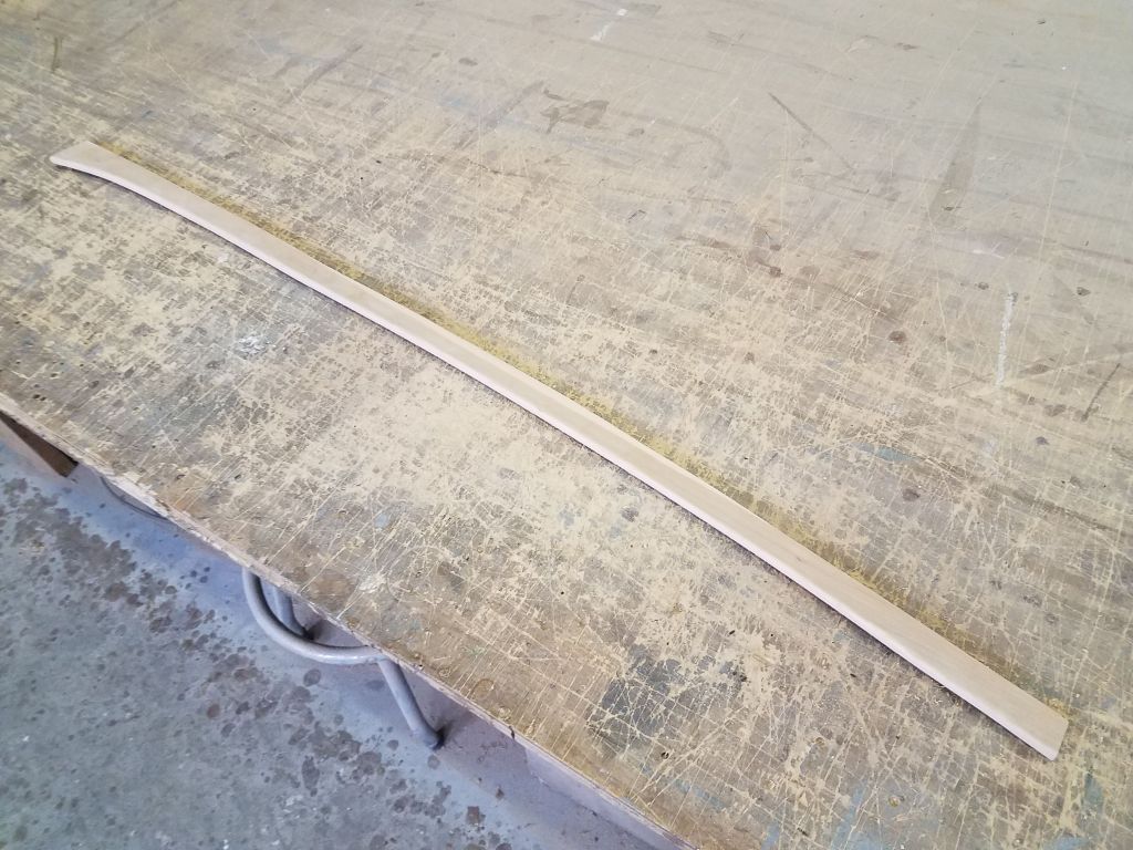
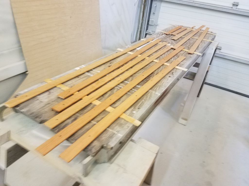
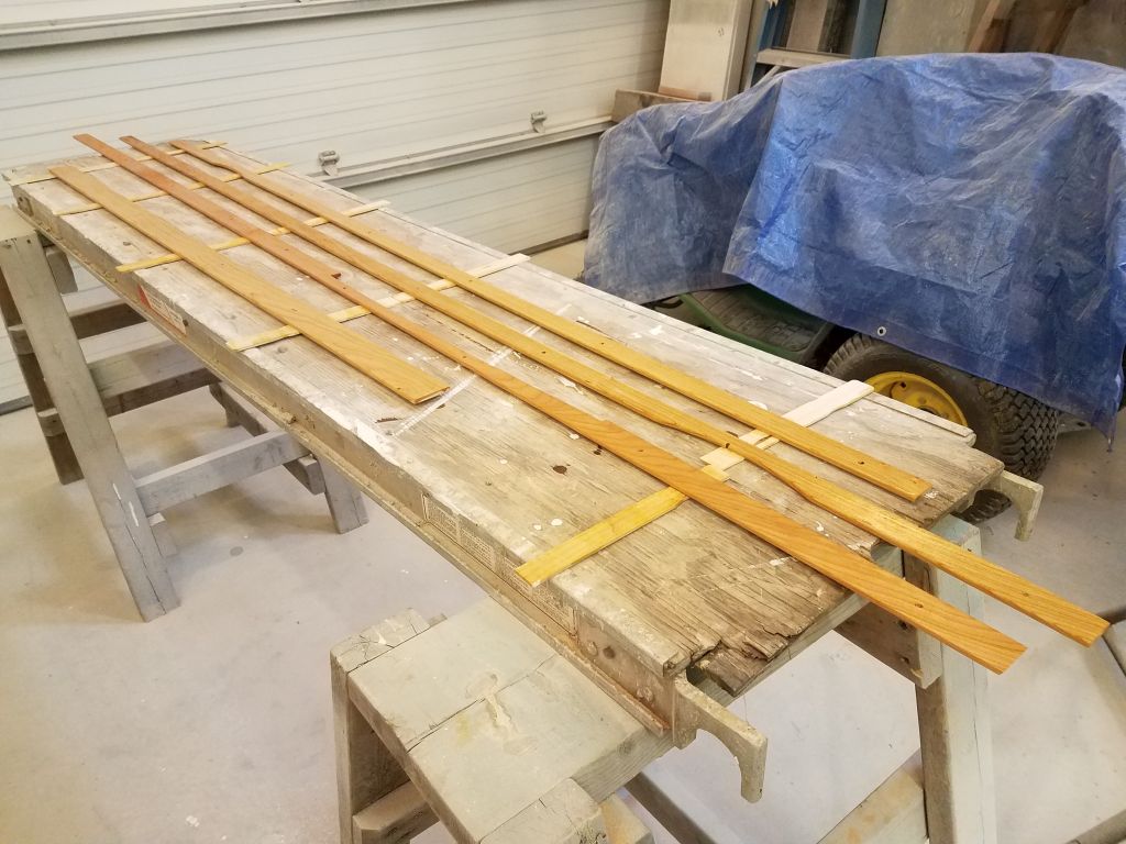
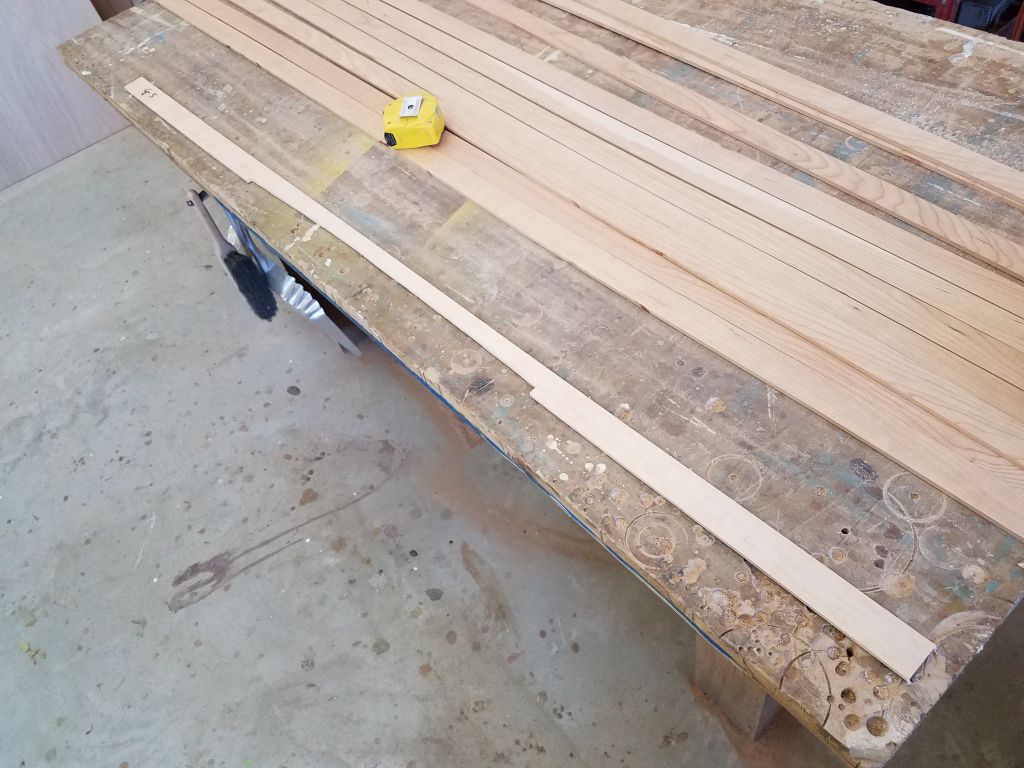
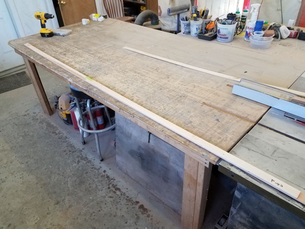
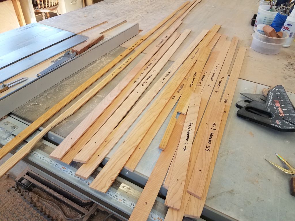
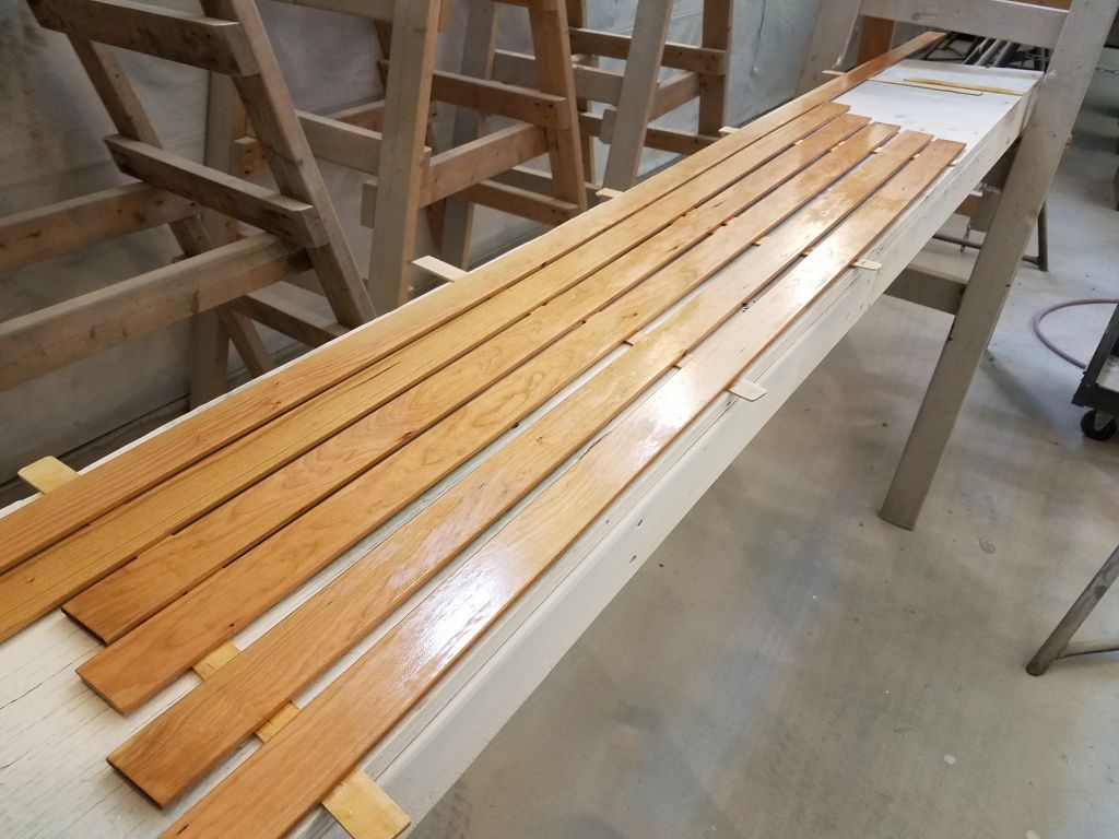
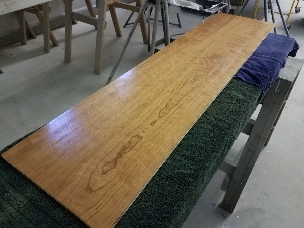
After lunch, I took some time to prepare several additional boards–which I’d earlier dimensioned and planed to the proper size, but had set aside for later use–for use in the sole, since I’d used up most of the material I’d already prepared. For these six or seven pieces, I sanded the chamfered edges on the top corners, cleaned them, then applied thinned varnish to all sides. These would be ready for use next time.
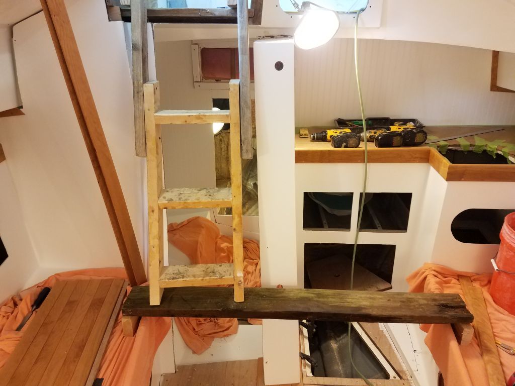
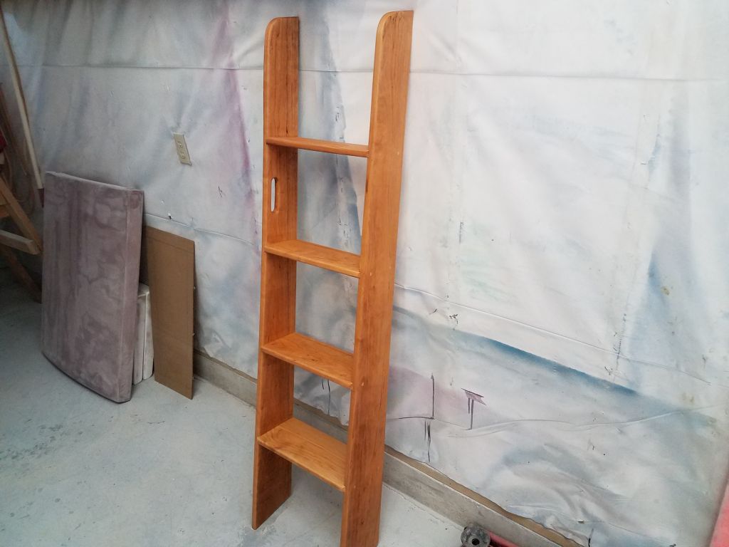
While I had varnish underway, I took care of the second coat on the interior doors and companionway ladder.

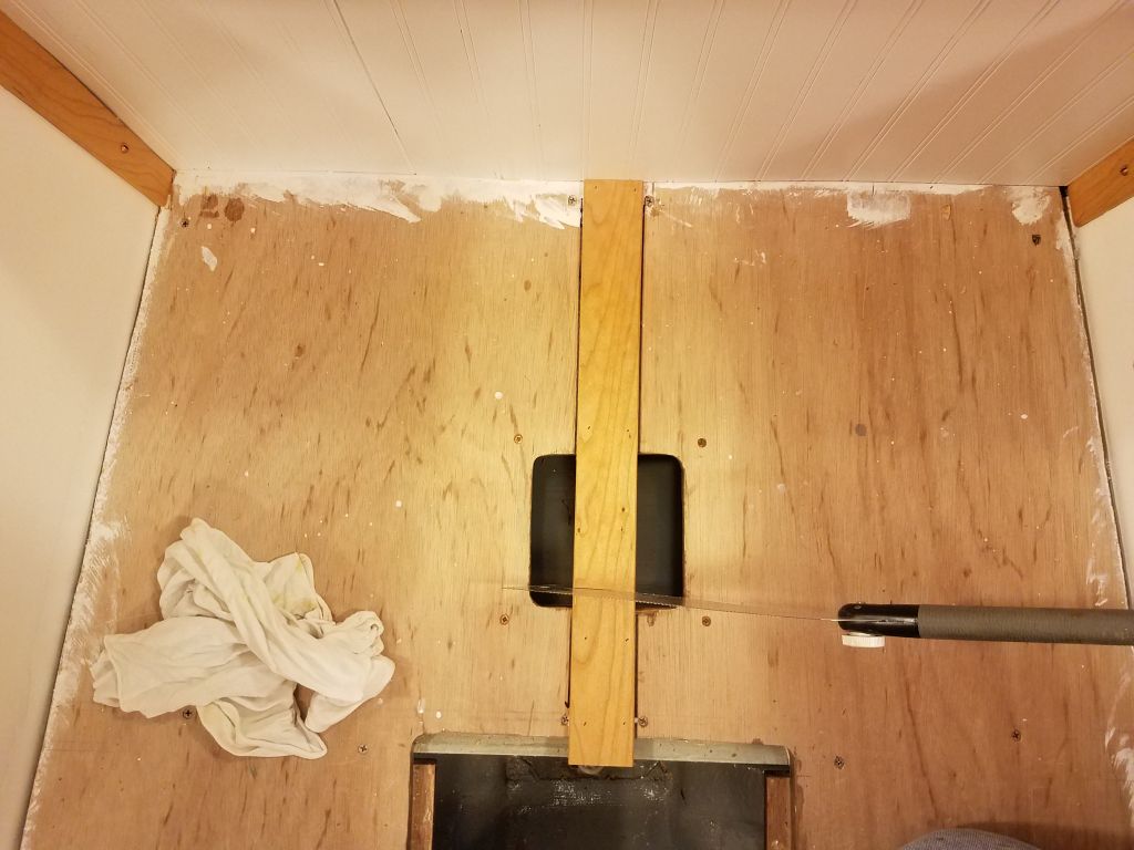
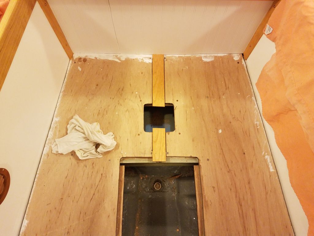
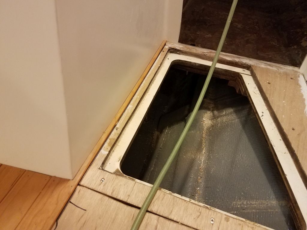
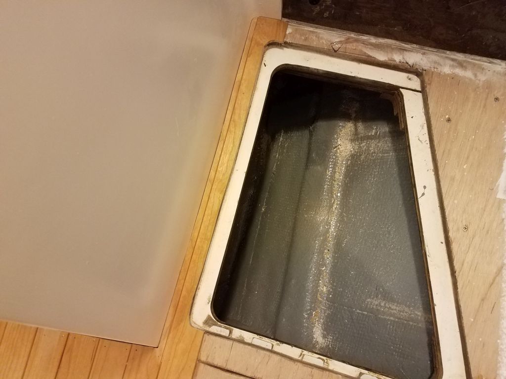
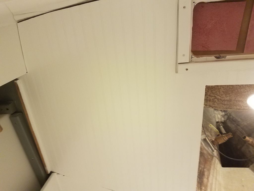
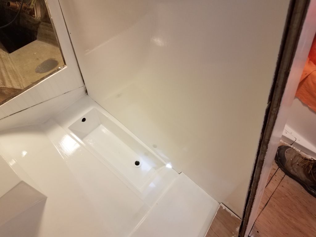
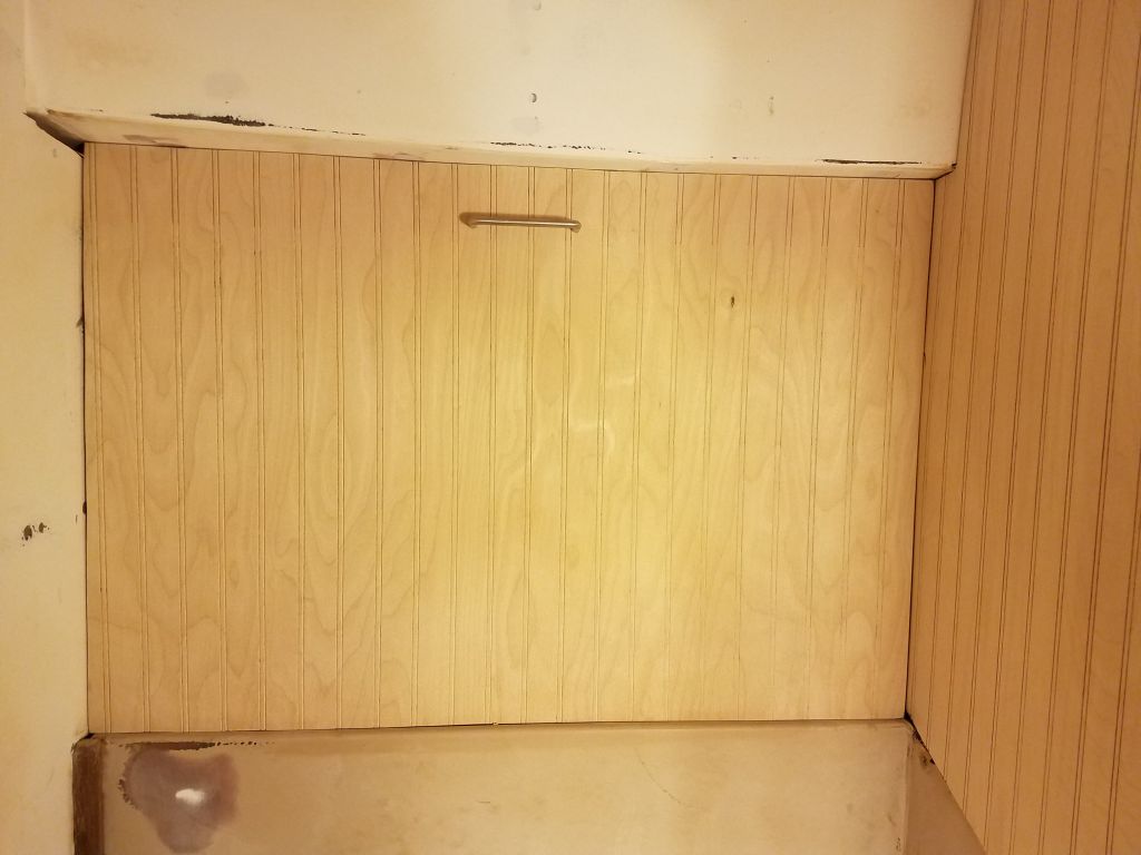
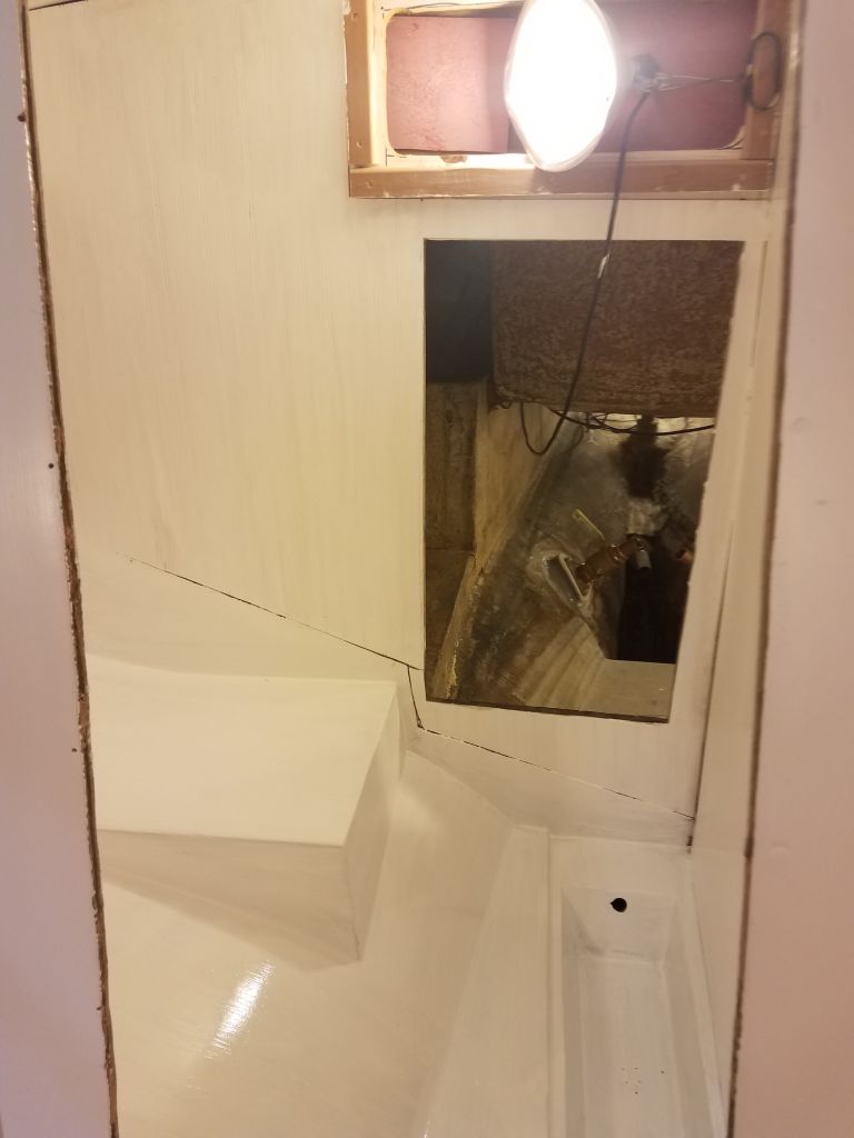
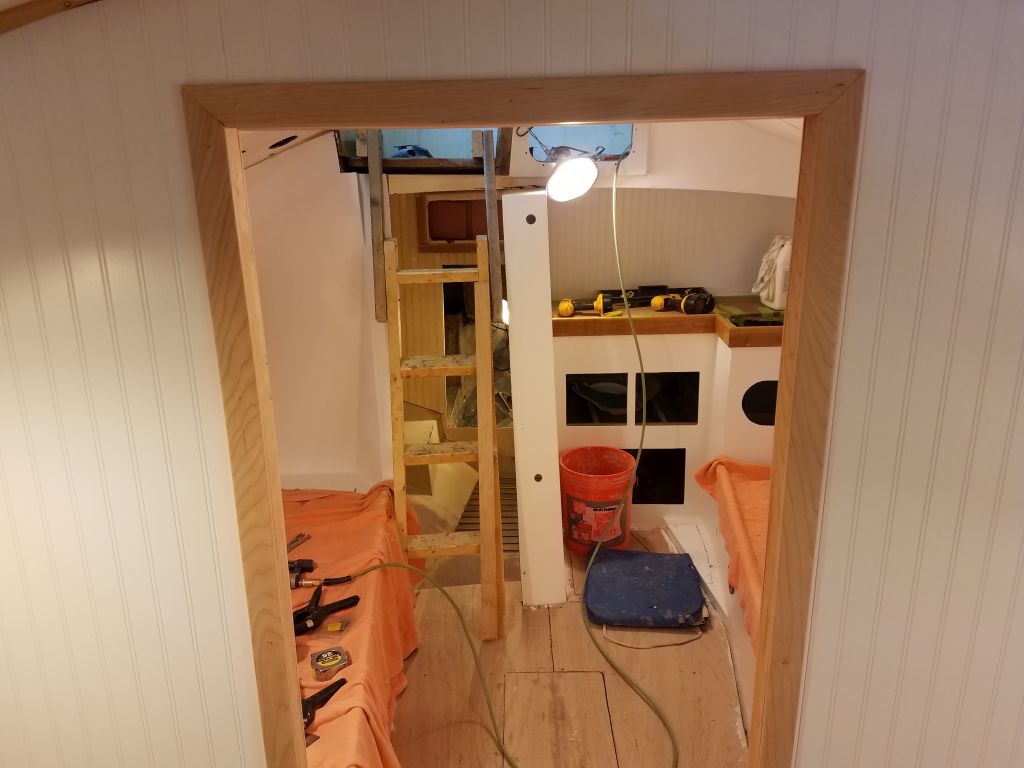
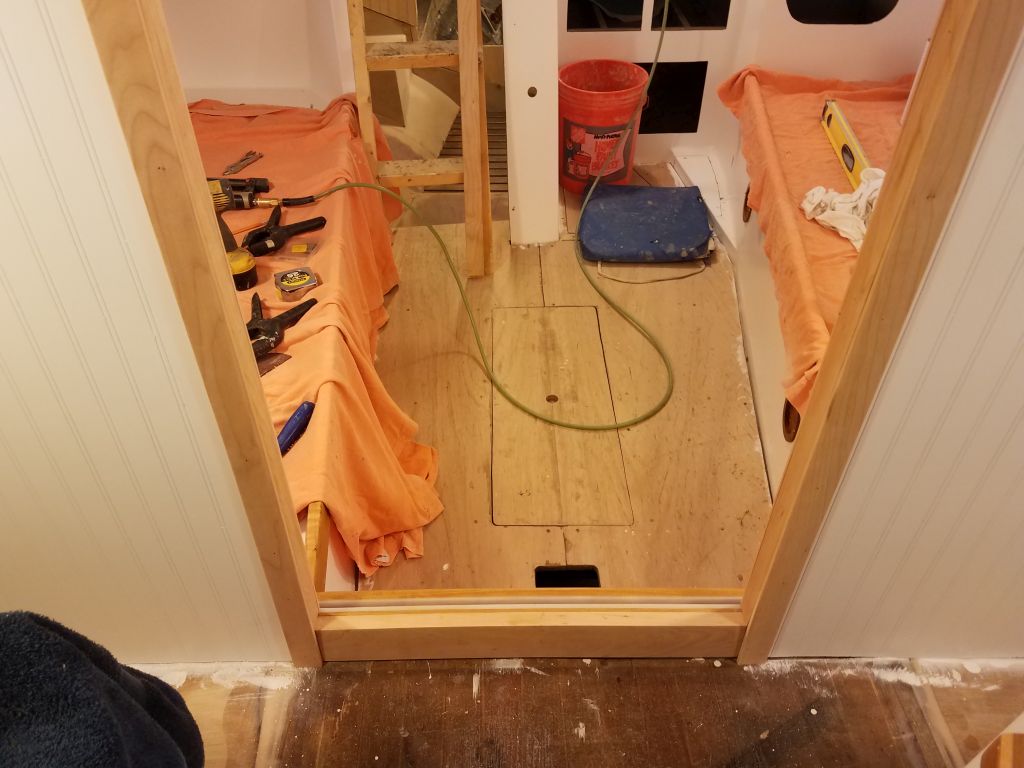
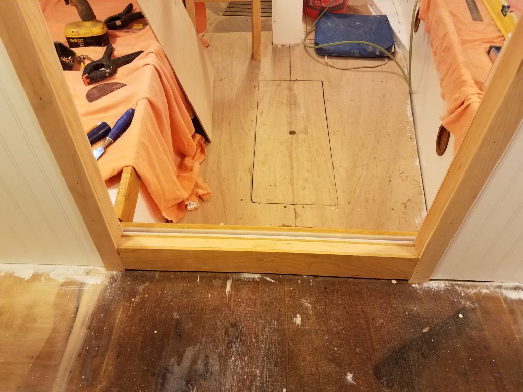
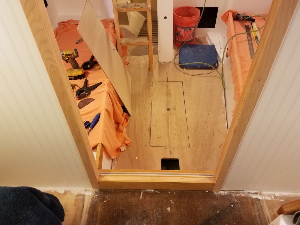
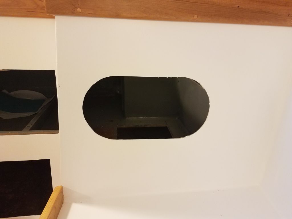
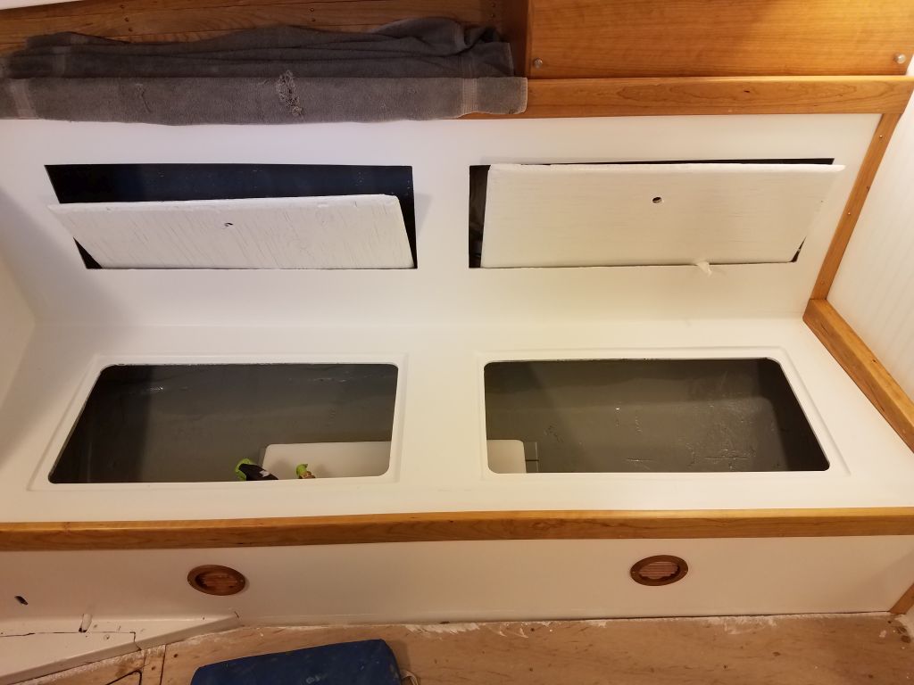
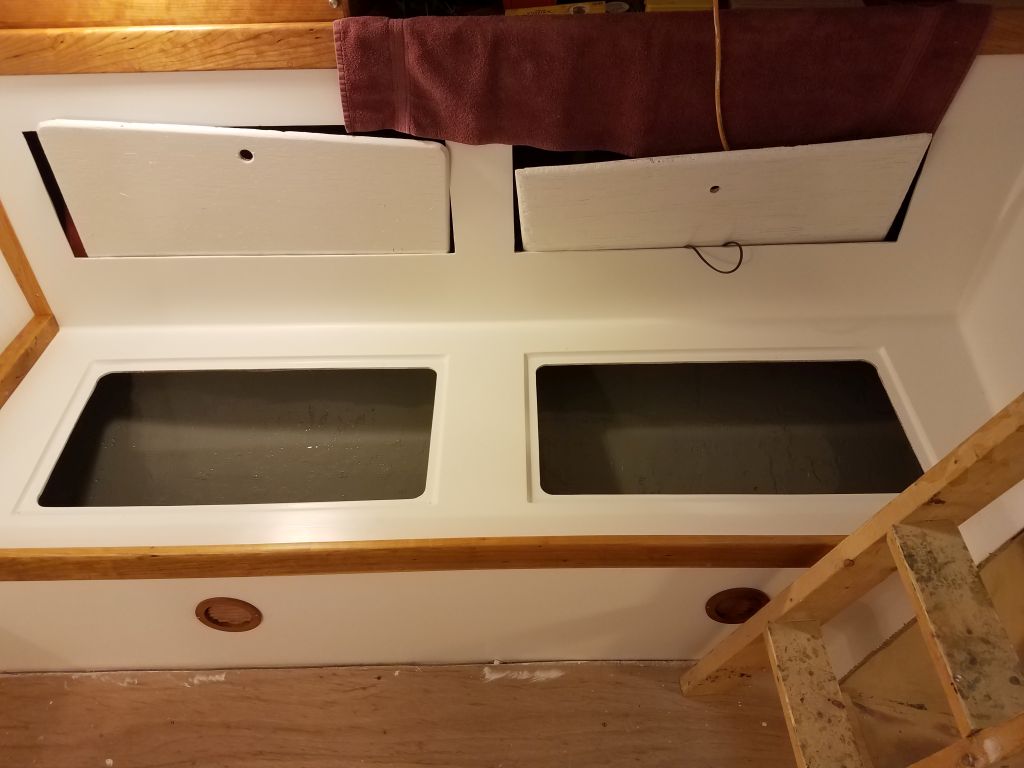
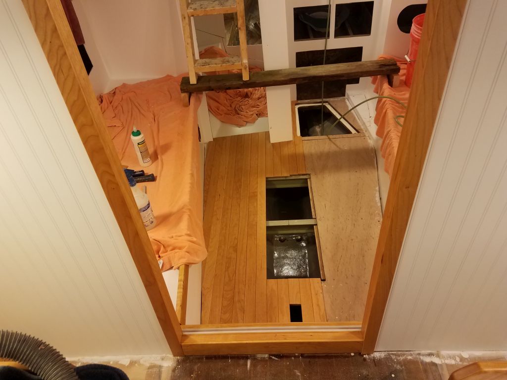
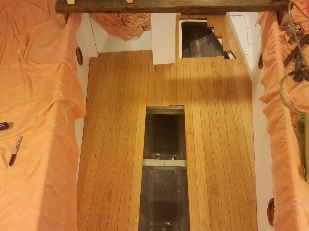
With a router and flush-cutting bit, I trimmed the excess lengths of cabin sole from the two main cabin hatch covers and openings. Then I could install the hatches to make moving through the cabin easier and safer as I continued work.
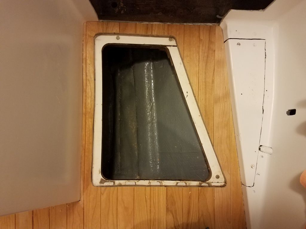
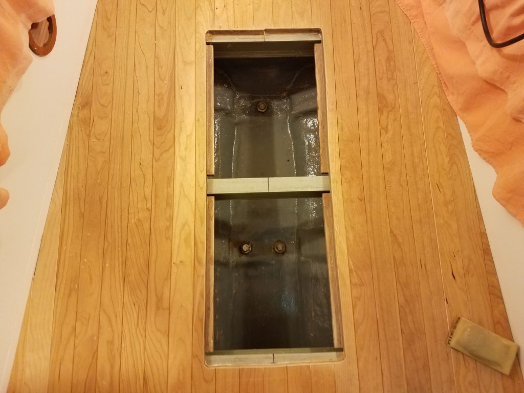
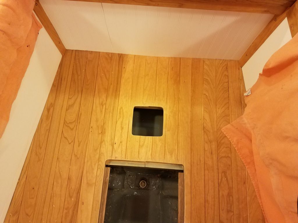
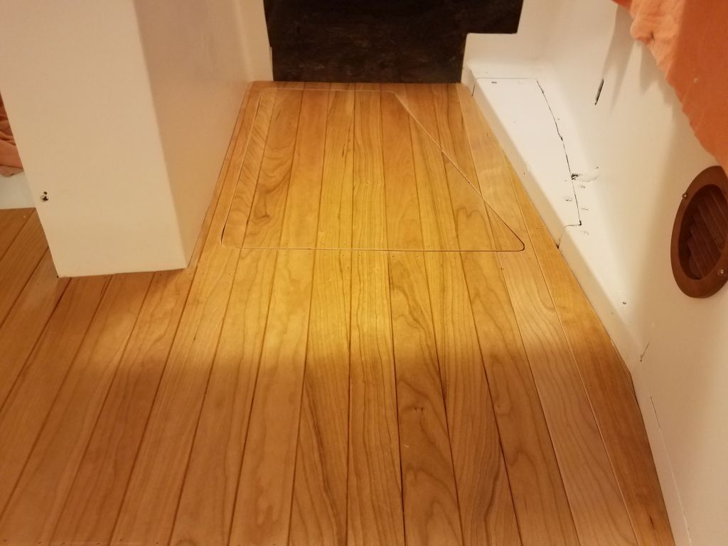

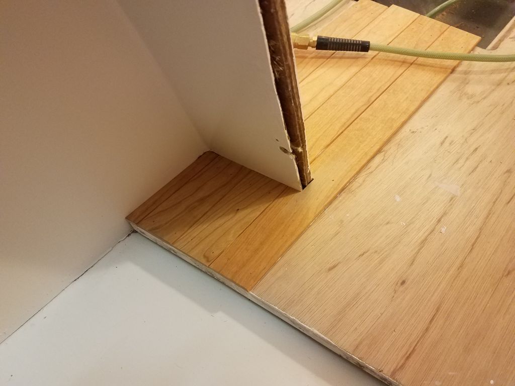
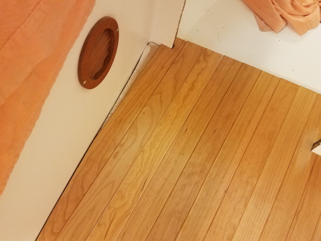
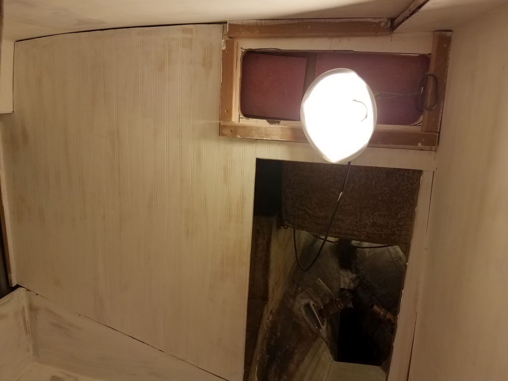
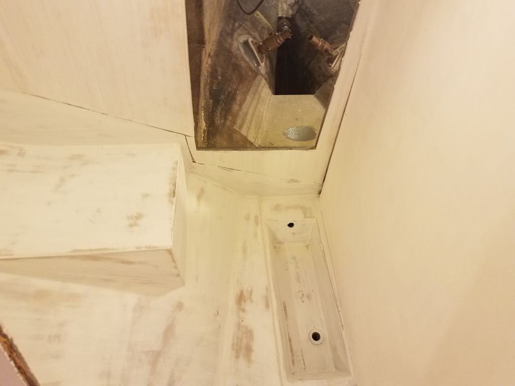
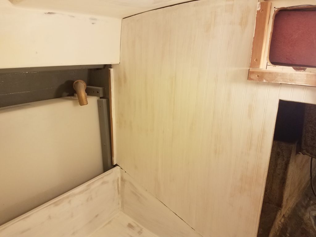
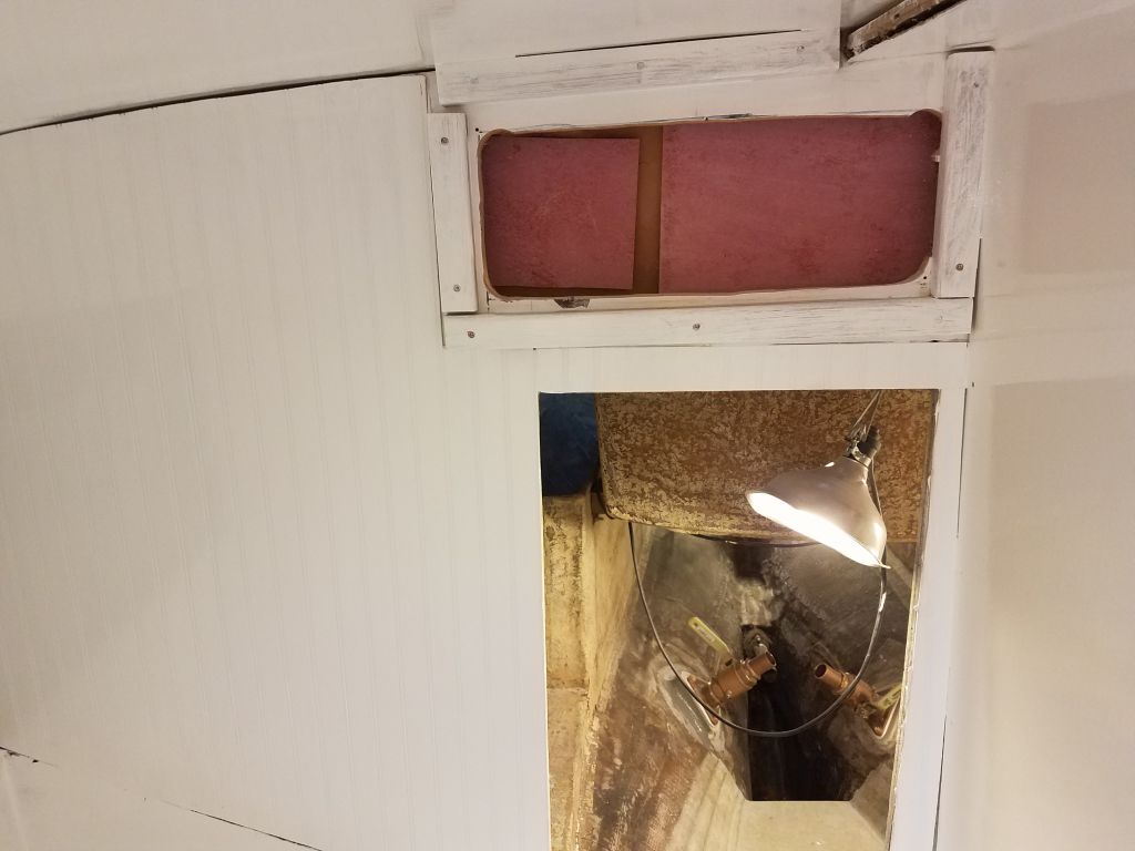
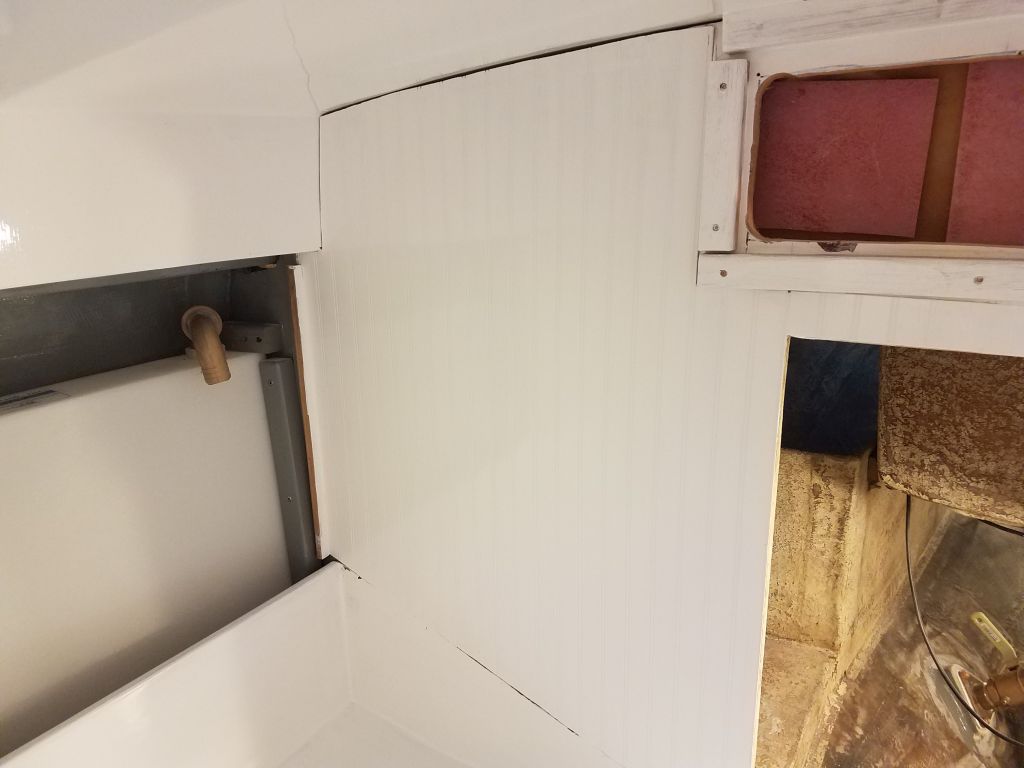
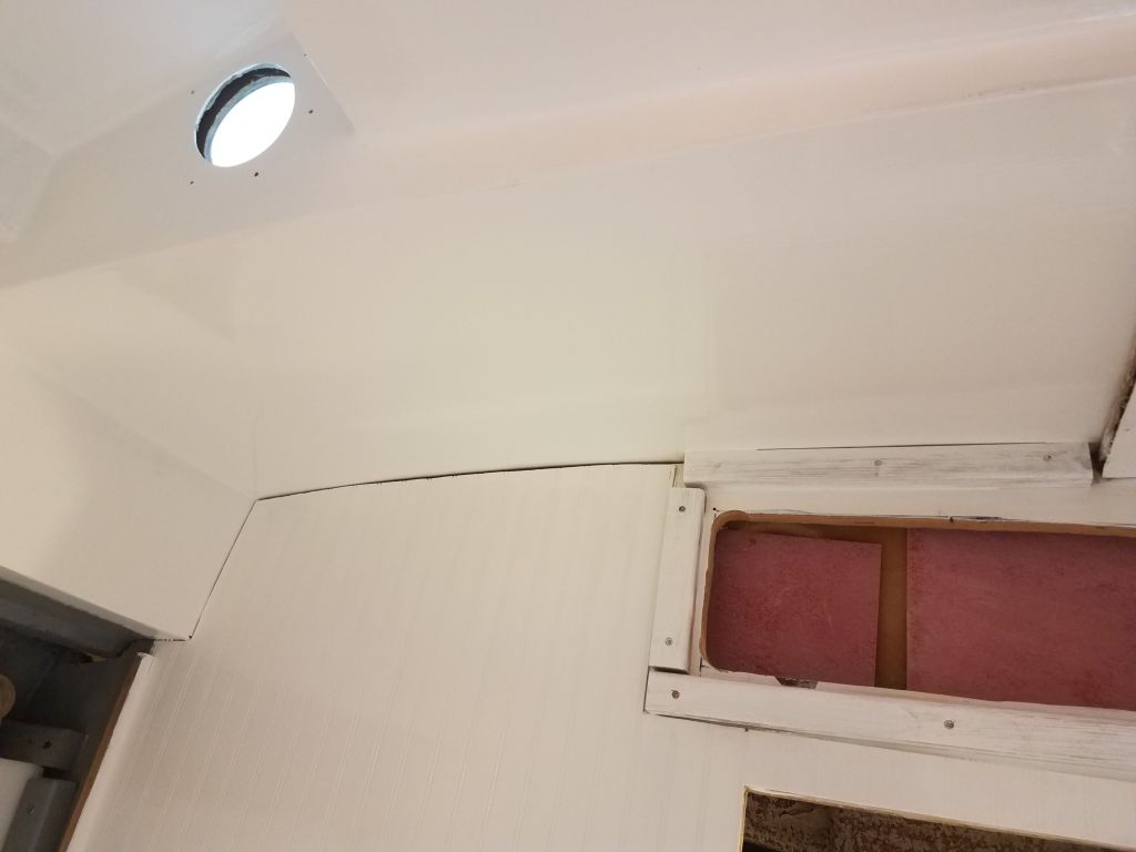
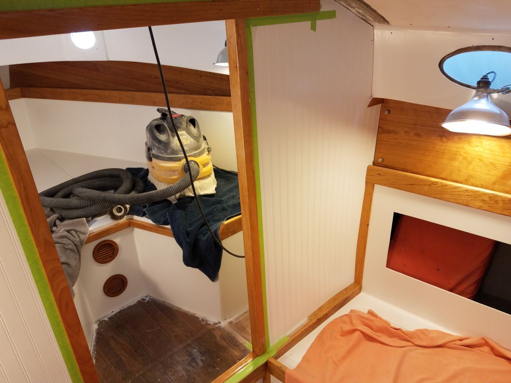
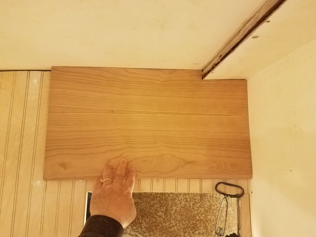
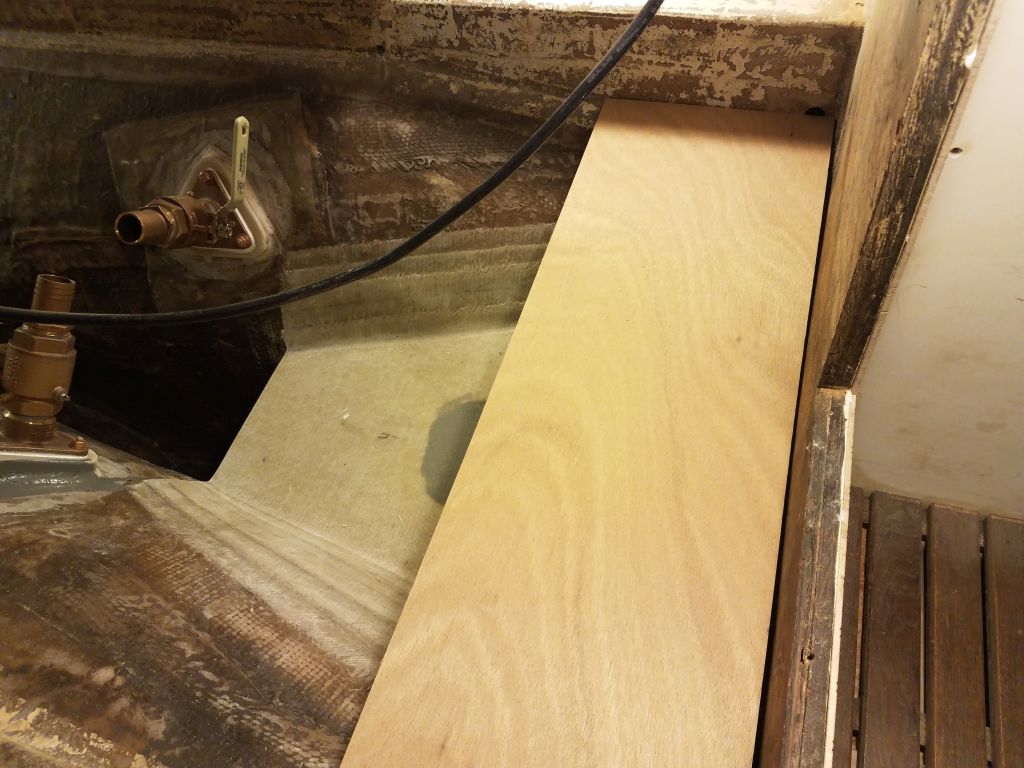
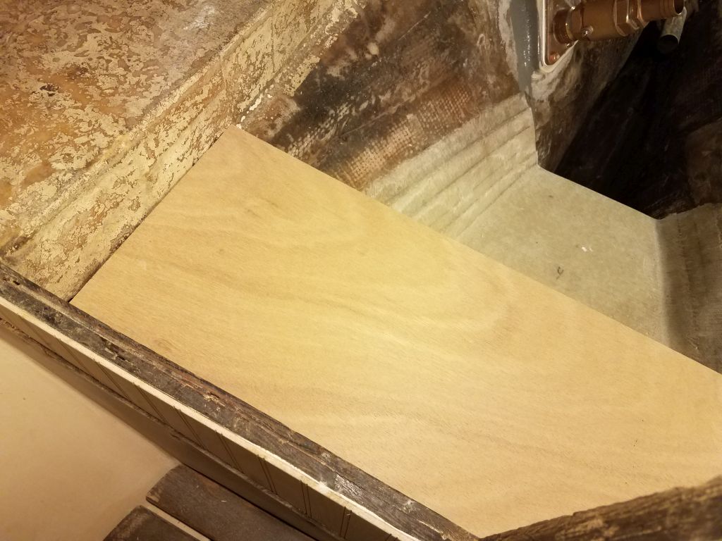
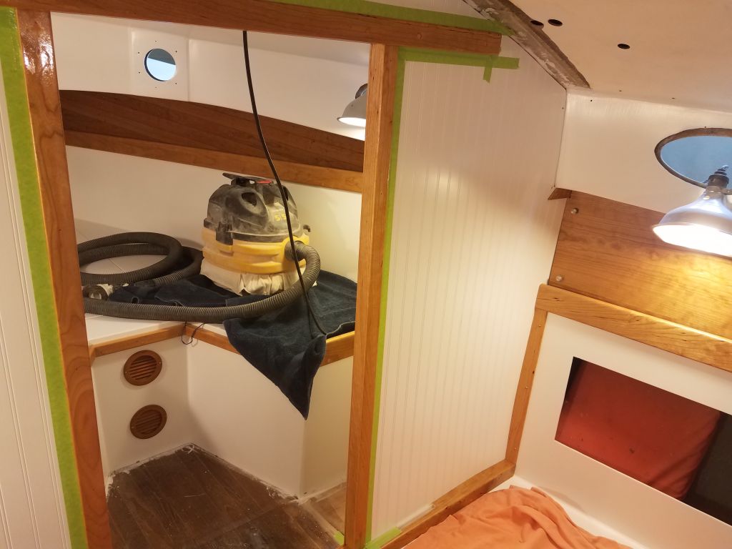
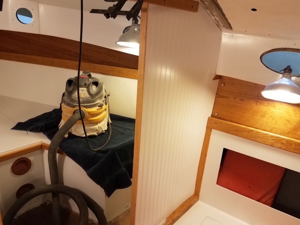
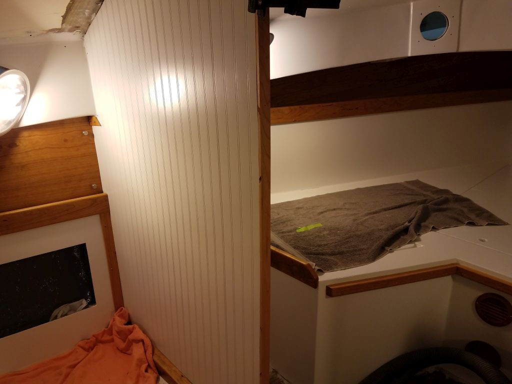
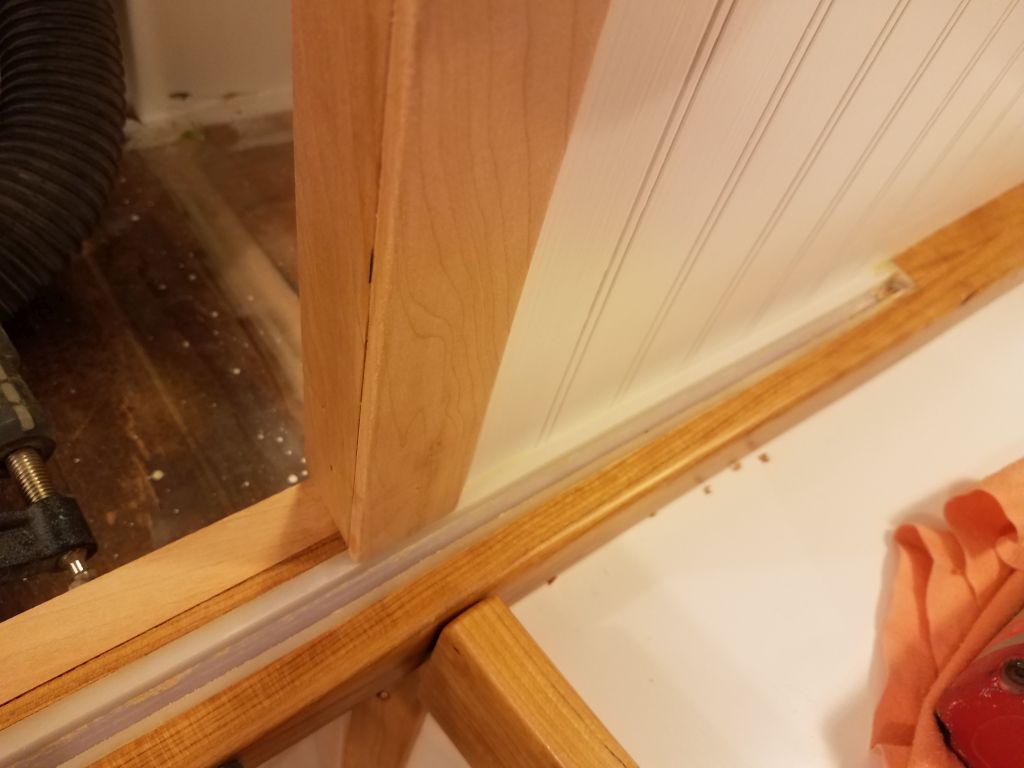
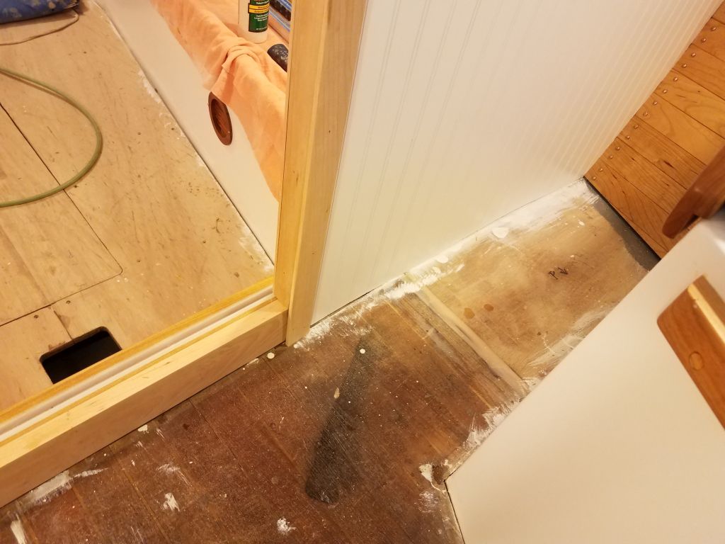
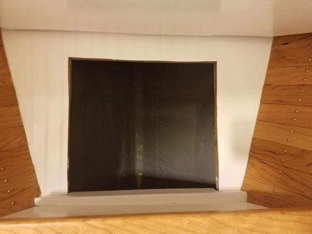
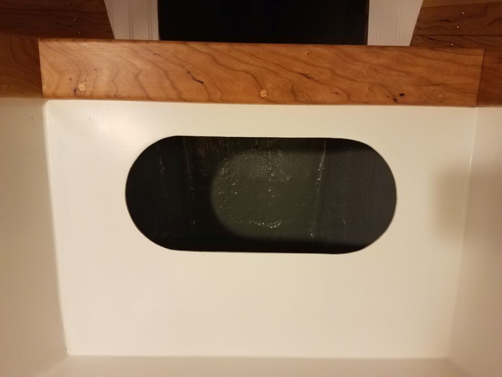
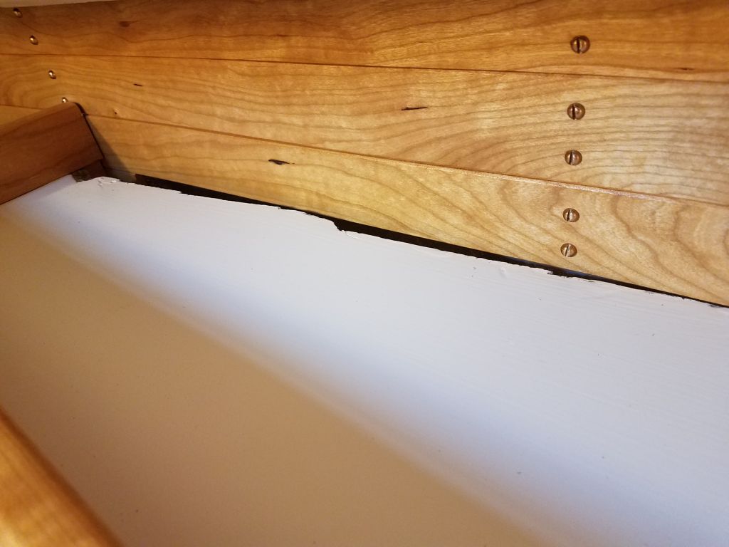
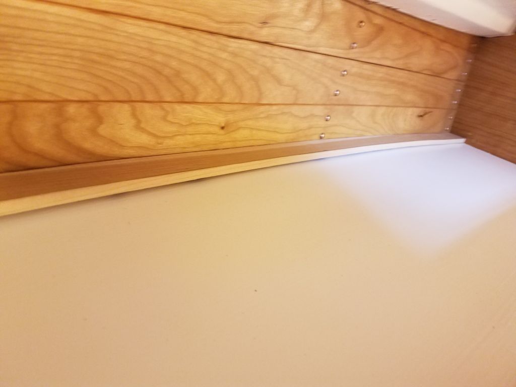
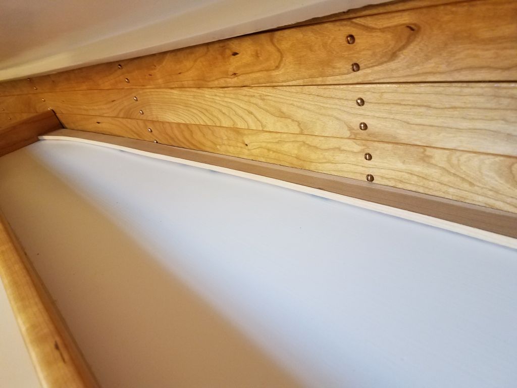
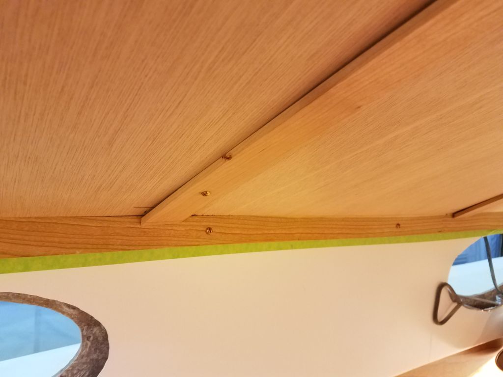
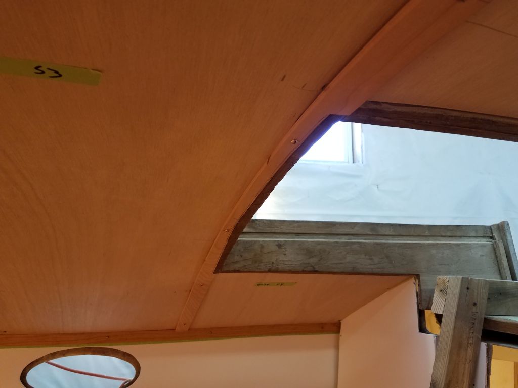
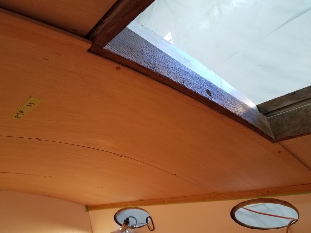
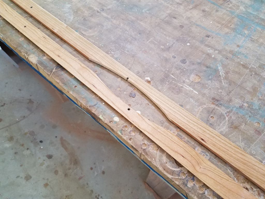
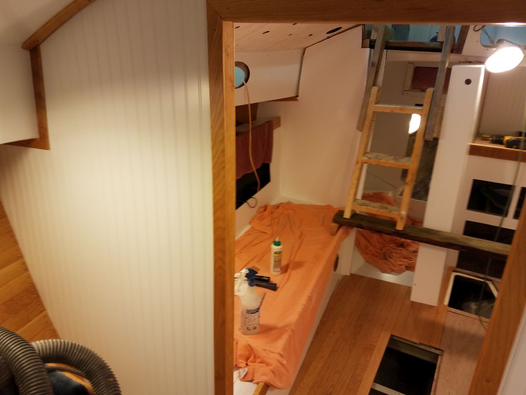
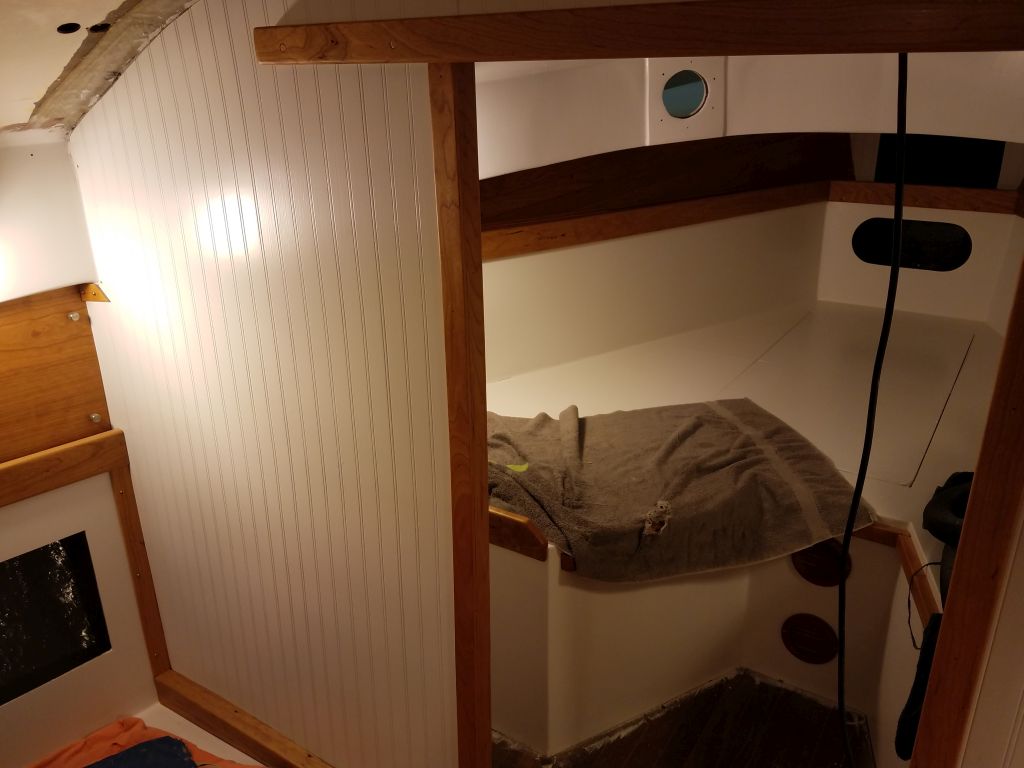
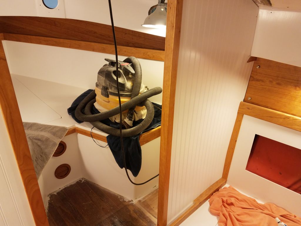
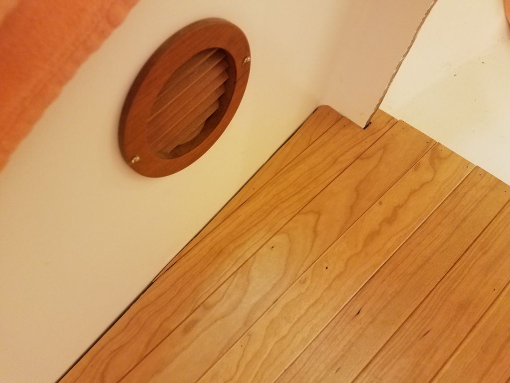
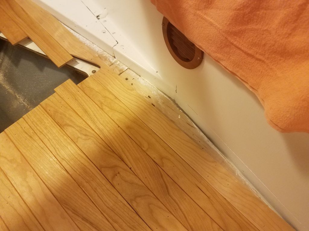
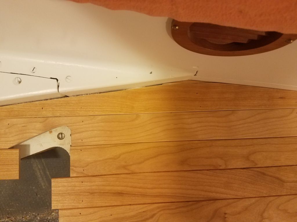
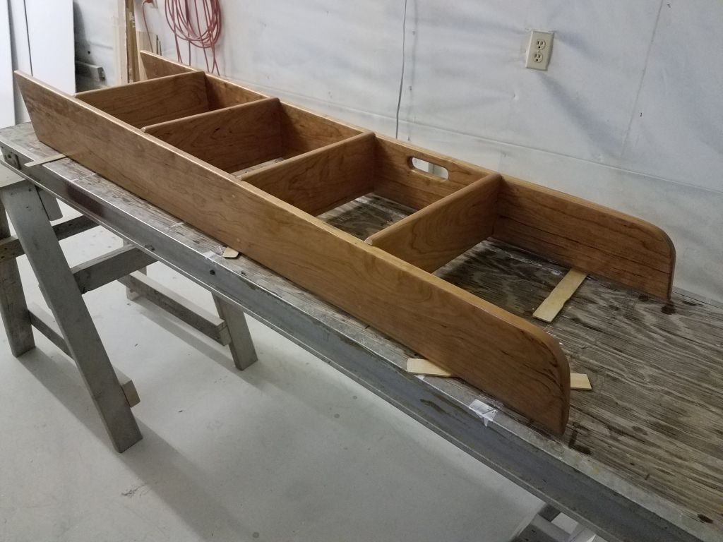
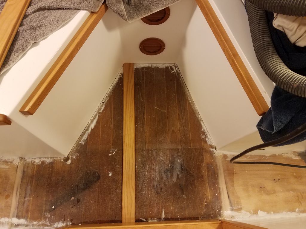
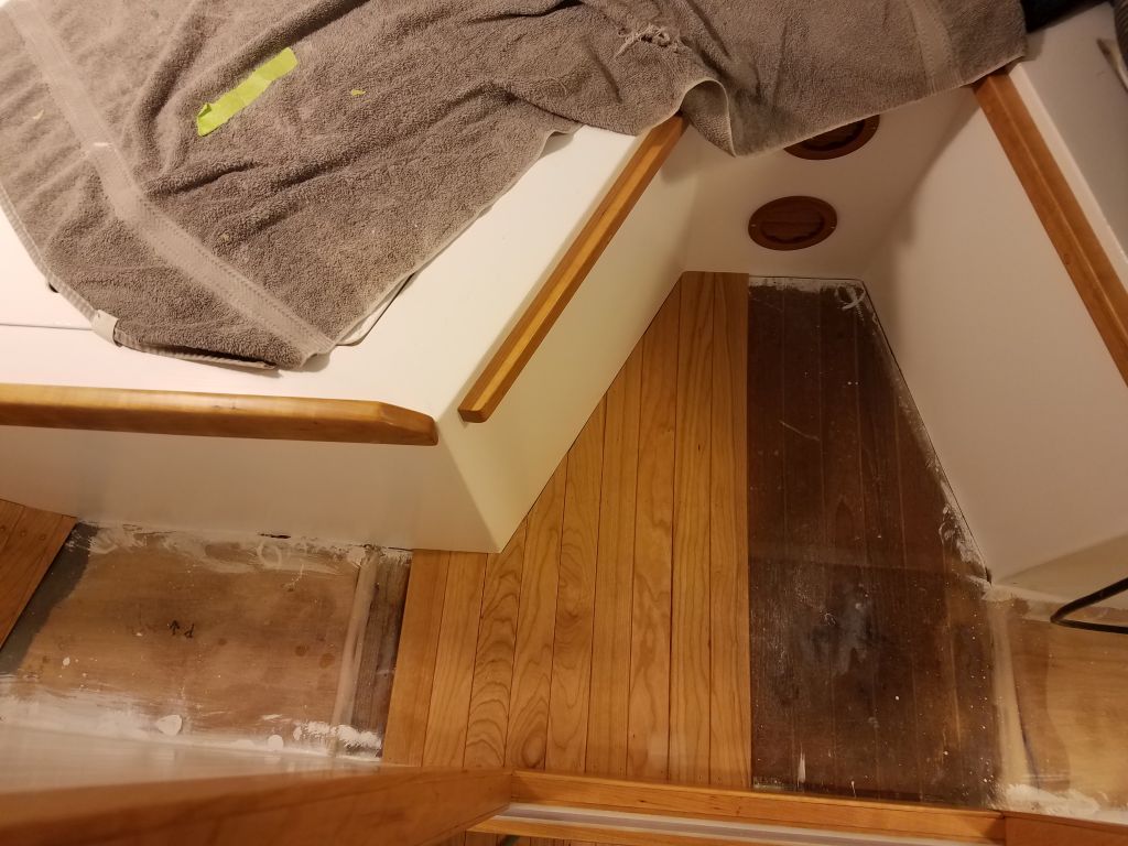
Using the offcuts from the main cabin sole, I started laying the sole in the forward cabin. Because at the moment I only had a few lengths long enough for the longest pieces here, I started at one side of the berth cutout and worked towards the outside of the boat from there, with the pieces growing progressively shorter as I went. The aft ends of the planks fit neatly beneath the door trim as planned. I had enough material to turn the corner into the narrow space aft of the port berth before running out, but fortunately this coincided nicely with the close of business. Next time, I’d be able to use the newly-varnished lengths of sole stock that I’d gotten ready earlier in the day.
Total time billed on this job today: 8.25 hours
0600 Weather Observation: 48°, clouds and fog. Forecast for the day: Clouds and showers, 50°