(page 149 of 167)

Salty 44

< Back to Salty

Wednesday

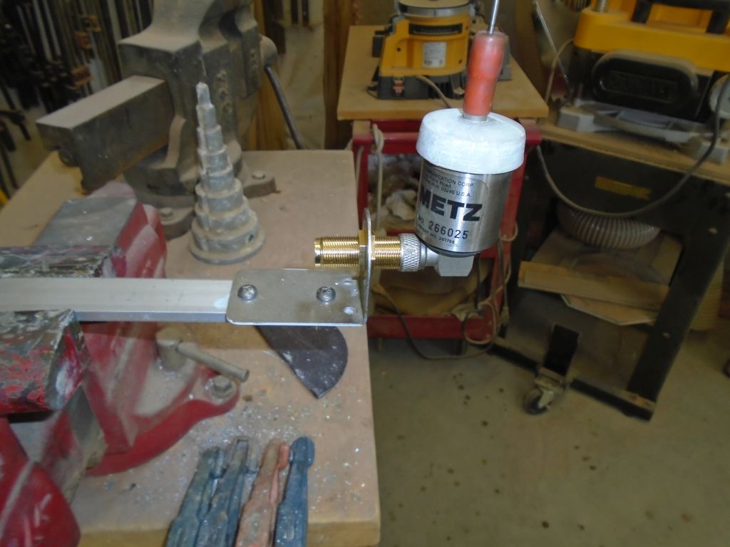
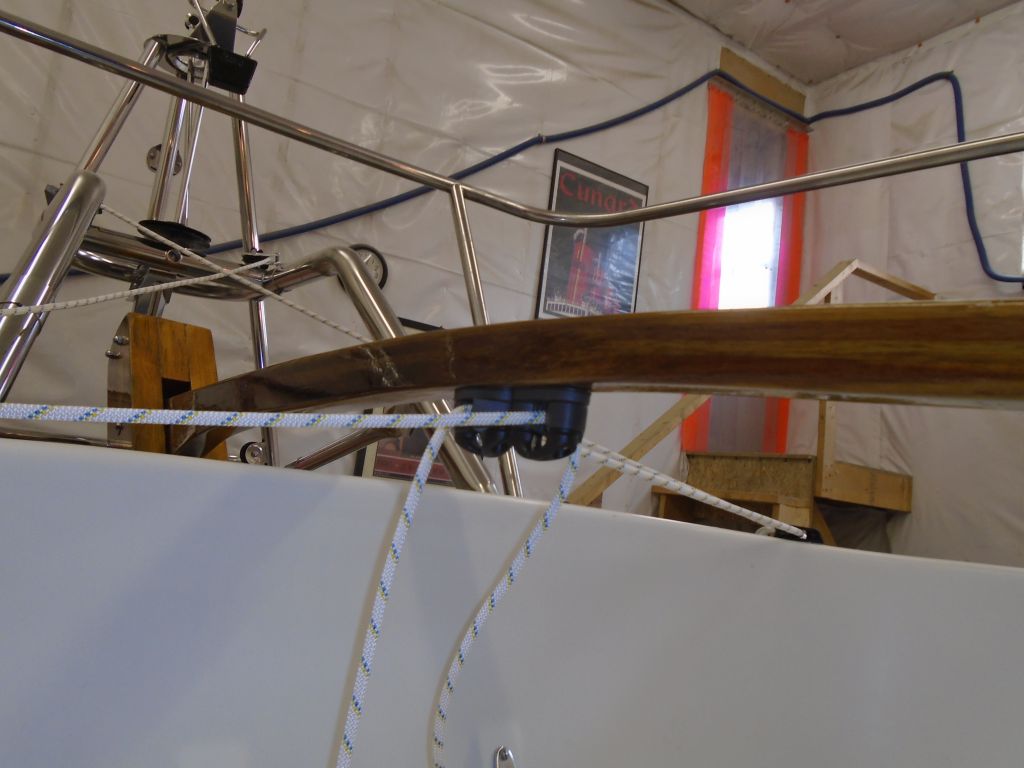
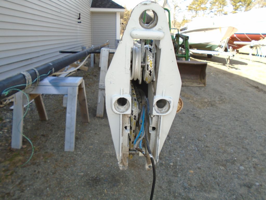
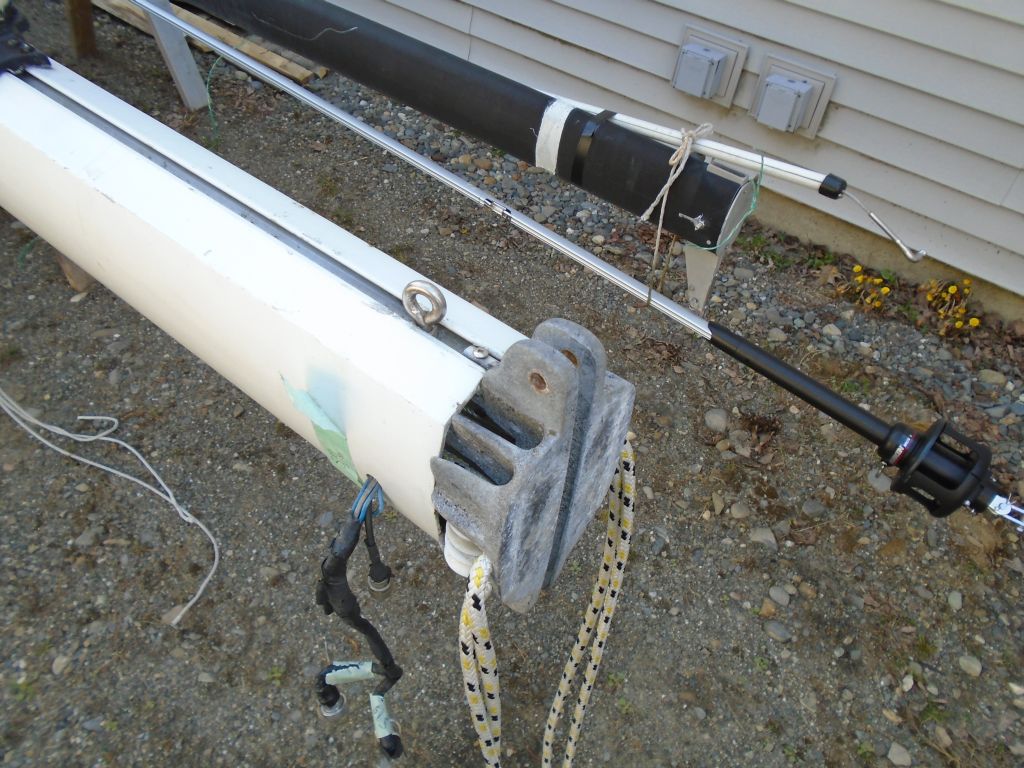
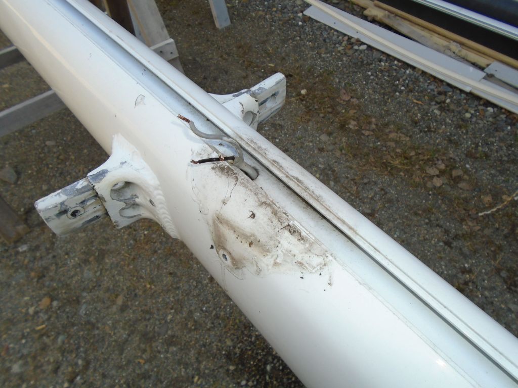
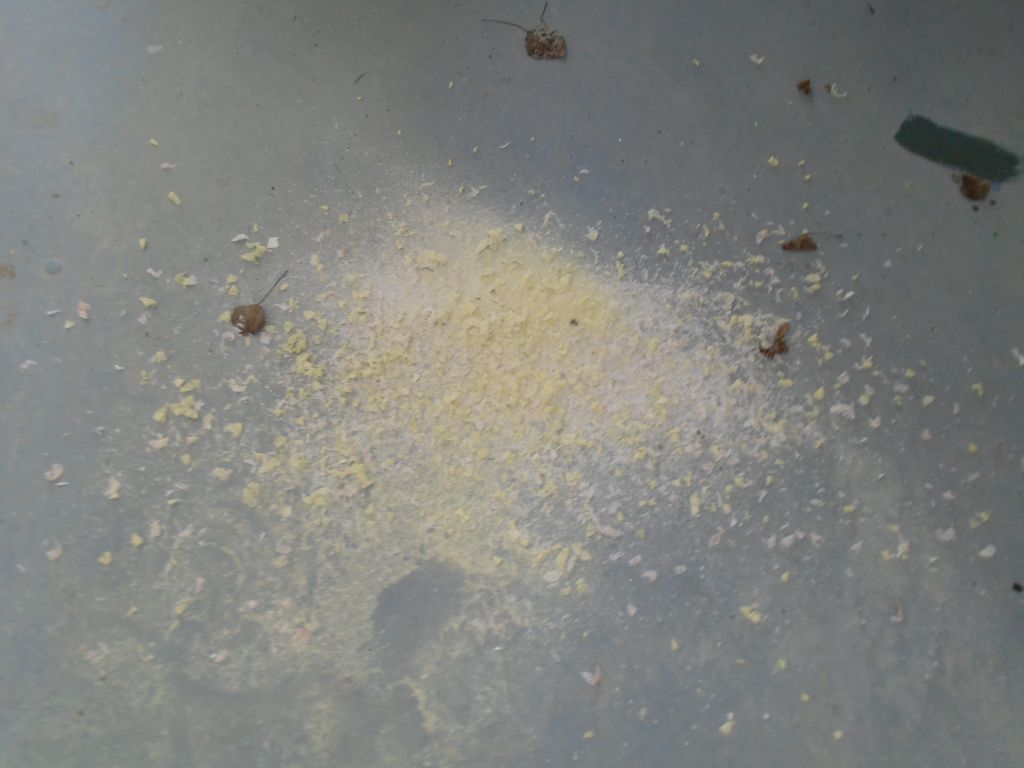
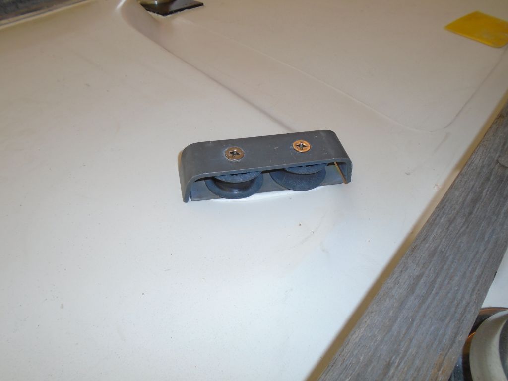
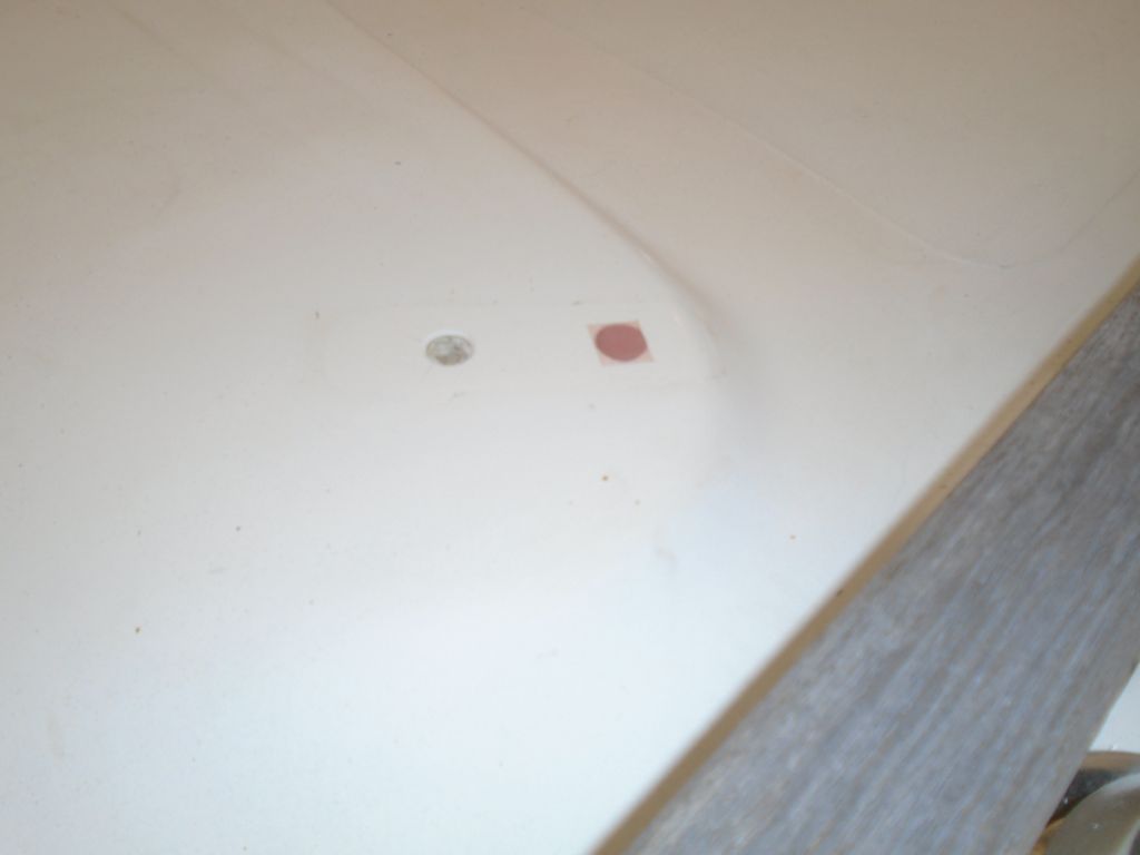
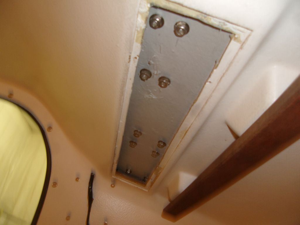
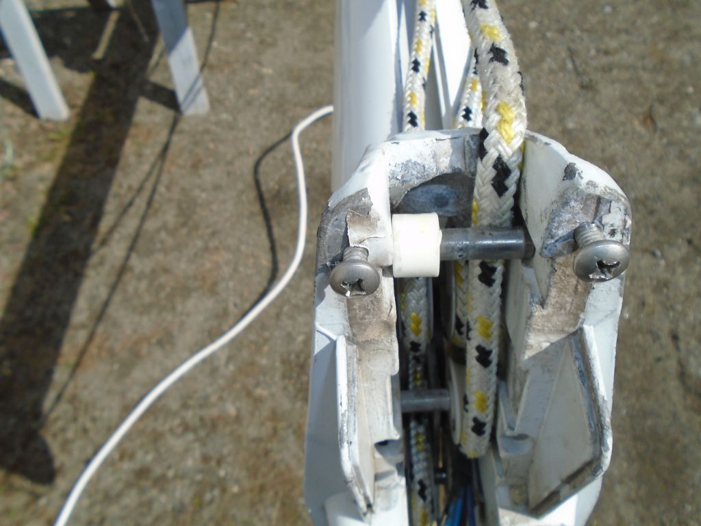
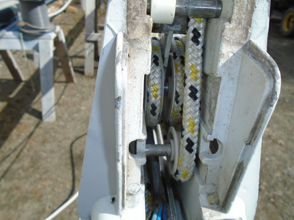
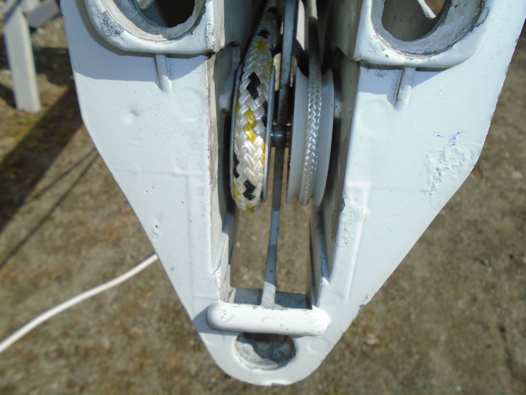
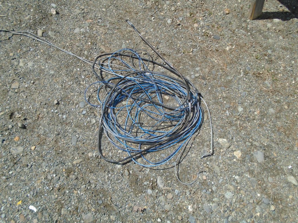
After some morning errands away from the shop, I turned to the mast wiring.  While I had the masthead casting off, I checked over the masthead sheaves, which all looked in good condition as far as I could tell, but it looked like there might be one damaged or partially missing, as evidenced by the plastic hub on the aftermost pin (first photo).  That pin just slipped into cast slots from above, and was contained by the masthead casting when it was normally in place.

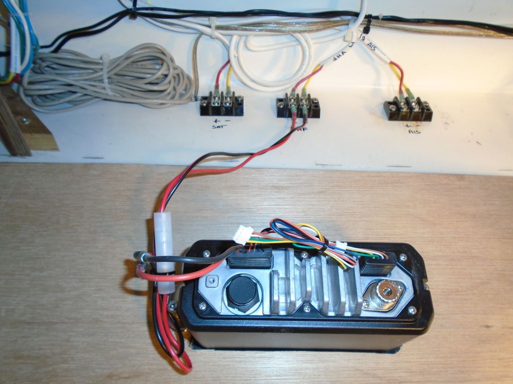
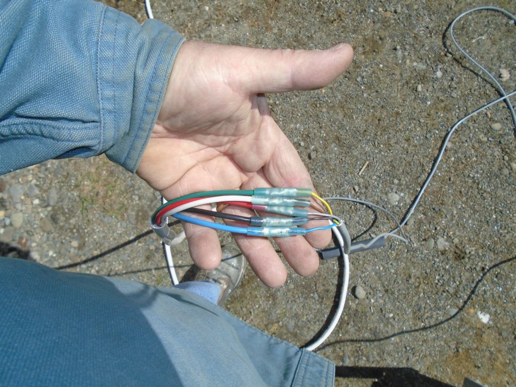
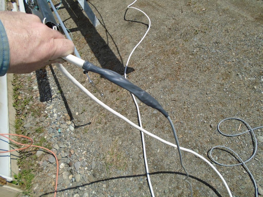
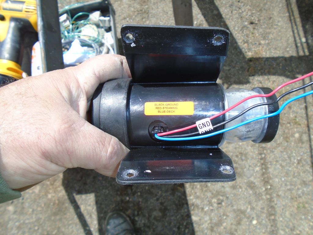
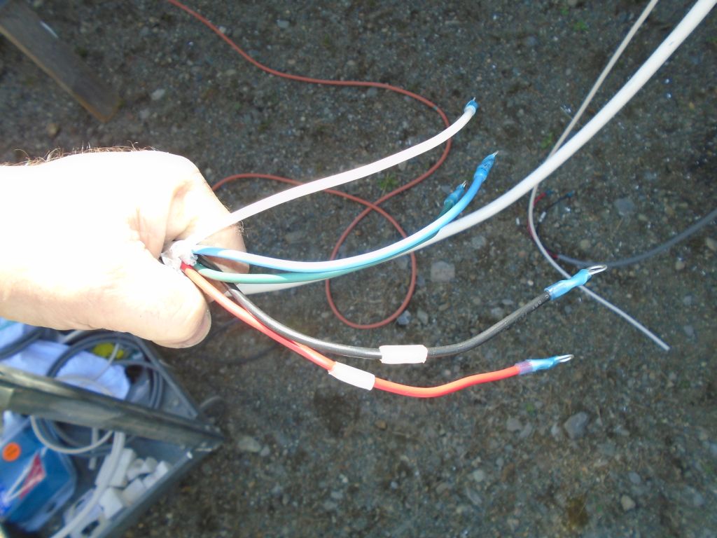
To extend the RTE wiring harness, a 5-conductor cable, I ended up using the same 14/5 cable that I’d run through the boat for this purpose earlier, which meant that wiring connection at the terminal block in the boat would be straightforward same color to same color.  This cable was heavier and larger than I wanted, but options were few and far between, at least with any products I’d trust and that were available in less than 1000′ parcels.  As least I knew it was quality wire.  Somewhere there must be a source for tinned 5-conductor cable in smaller gauge sizes and nominal overall diameters, but I couldn’t find it and after a time further looking was only wasteful.

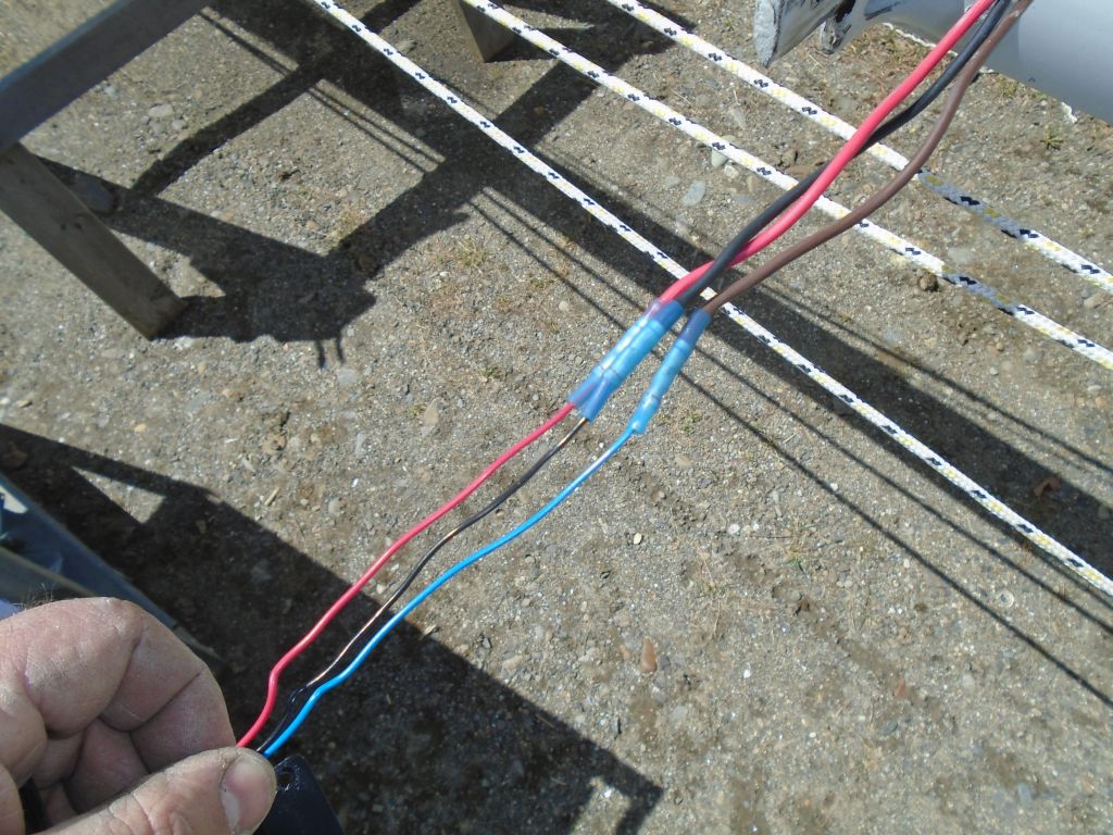
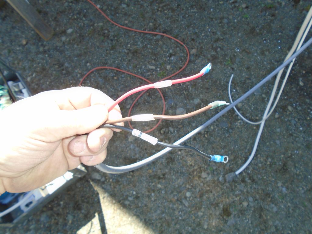
In the event, I connected the new wire to the existing harness, noting again the color conversions between the two, and for added longevity and strength within the mast, I added a sheath of heat shrink over the entire splice.

I chose to use the existing wires (which had powered a tricolor masthead unit) to pull the new cable down from the top.  So I heavily taped the new harness to the old to help it on its way through whatever course it took down the top part of the mast.  In addition to the 14/5 cable, I also secured a new VHF cable to pull through the mast and replace the existing.

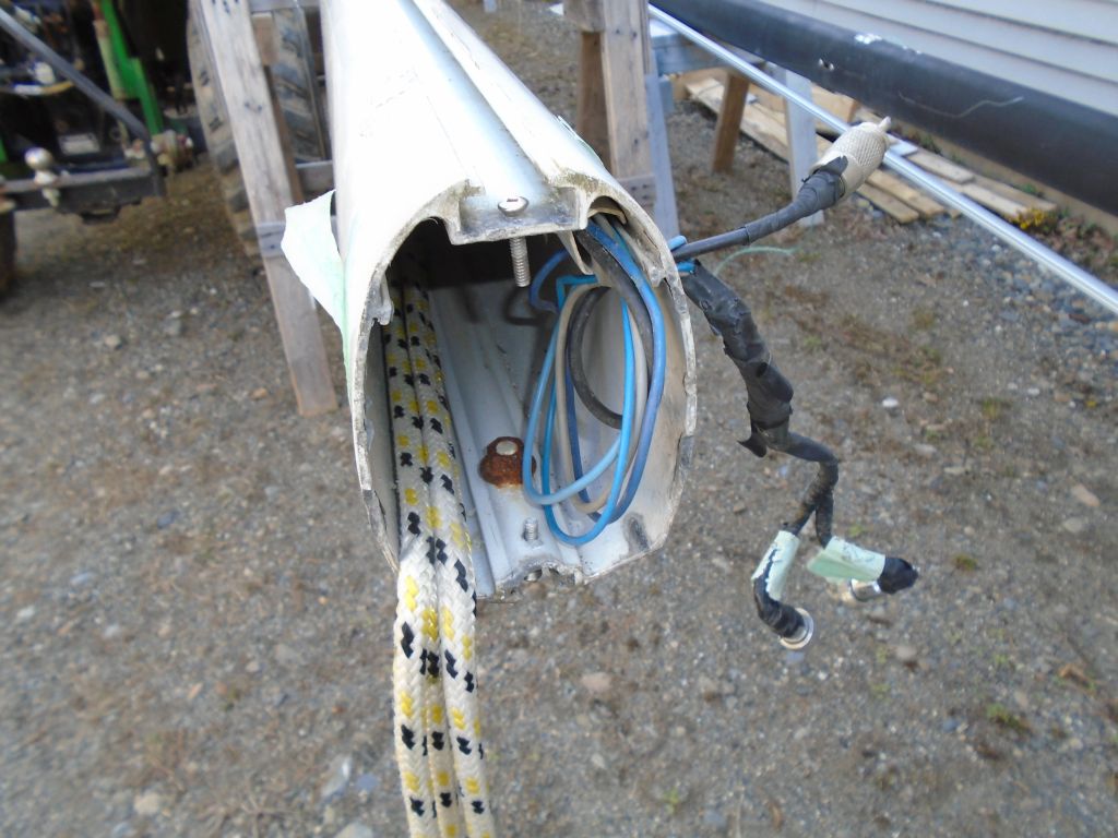
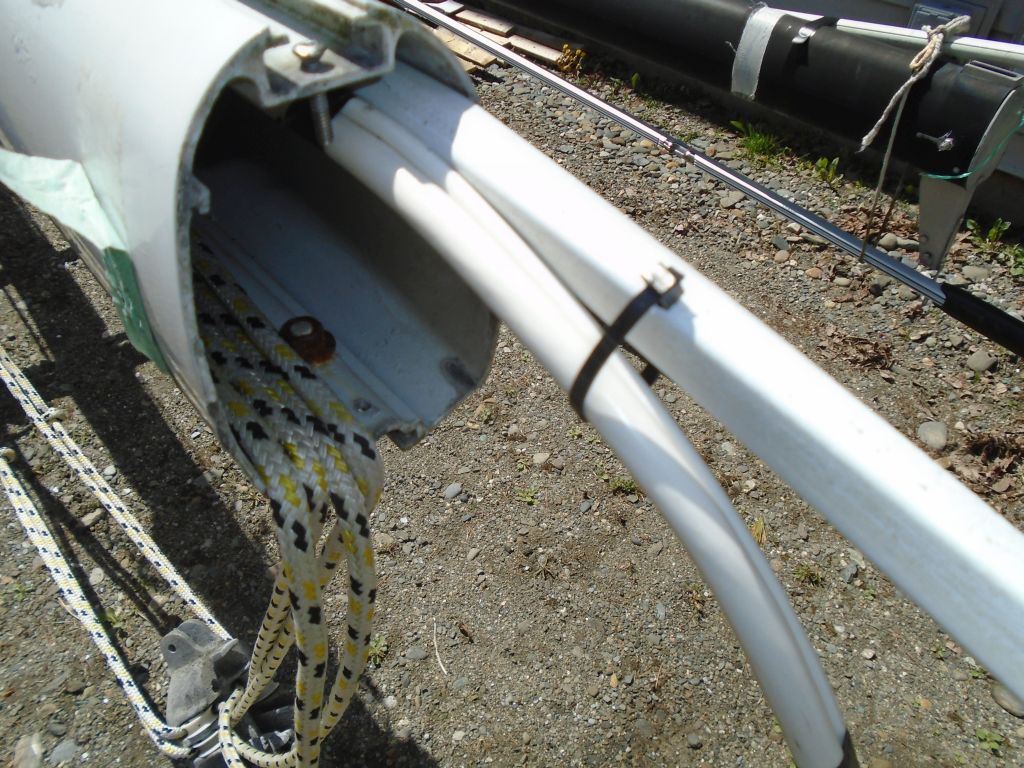
The wires from the masthead ended up in a length of plastic conduit within the mast when they reached the steaming light location at the spreaders, along with the three-wire harness from this light.  The conduit slipped over an extruded lip on the inside of the mast, and therefore was removable as a whole.  At the steaming light, I secured a length of messenger line to the existing wires before starting to pull out the entire harness.

mast5-42016

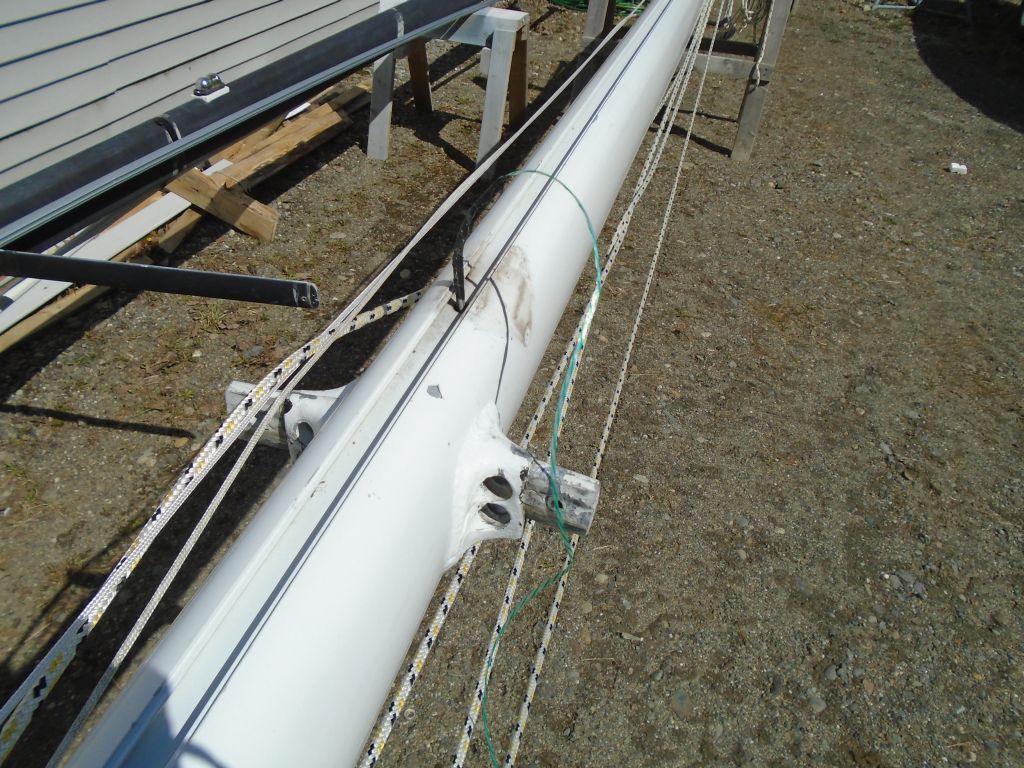
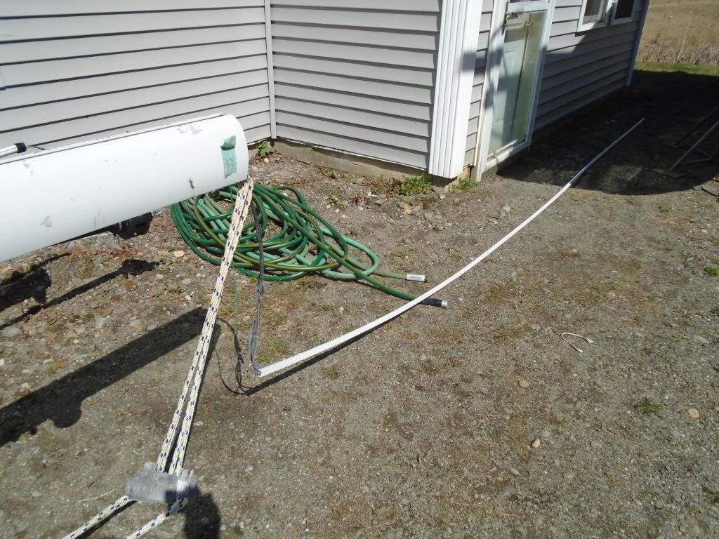
From there, it was relatively simple to pull out the conduit and old wires from the bottom.  The new harness fed in fairly easily from the top once I got it going, which suggested it had an unimpeded path through the spar.

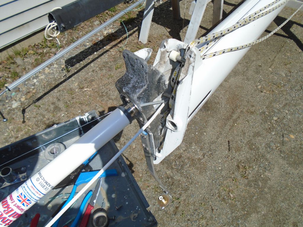
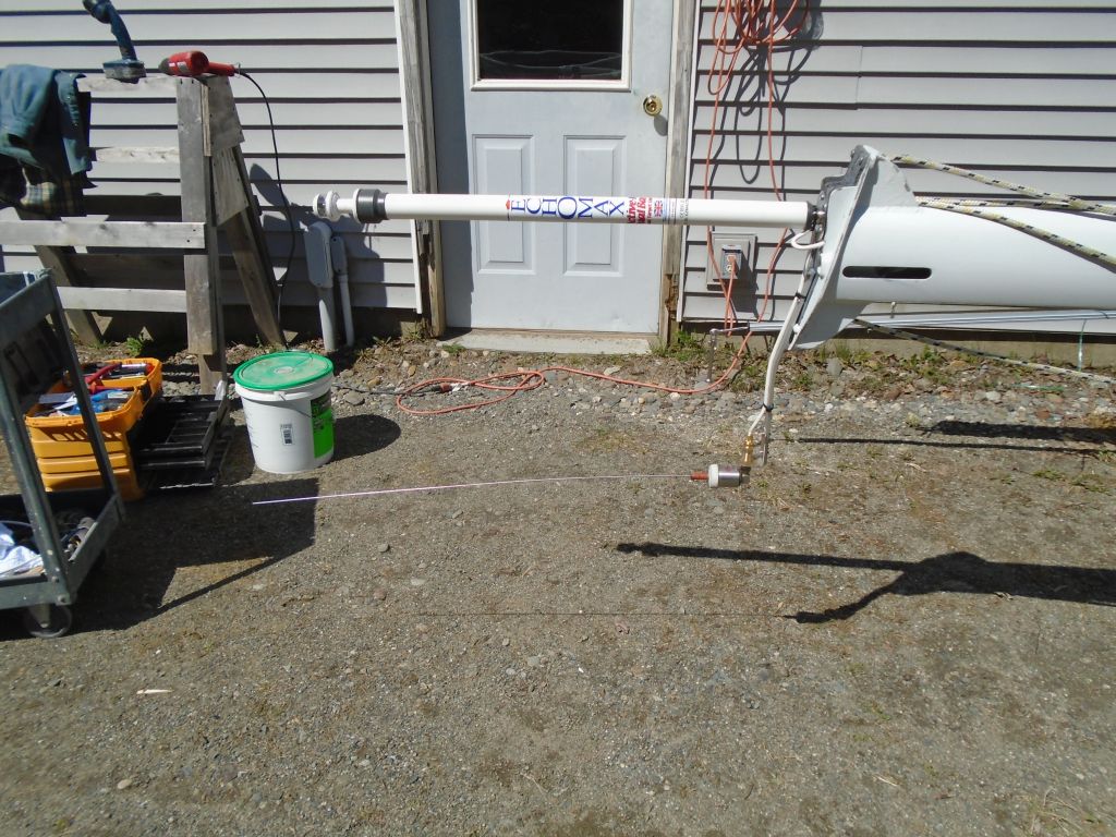
I left some slack in the masthead wires just below the top of the mast to allow the masthead casting to be removed for sheave access in the future, then resecured the masthead–with RTE and VHF extension attached–back in place before making up the end of the VHF cable as required.  After photos, I removed the VHF antenna for safekeeping, but the RTE was now a permanent fixture by virtue of its hardwired and sealed construction.

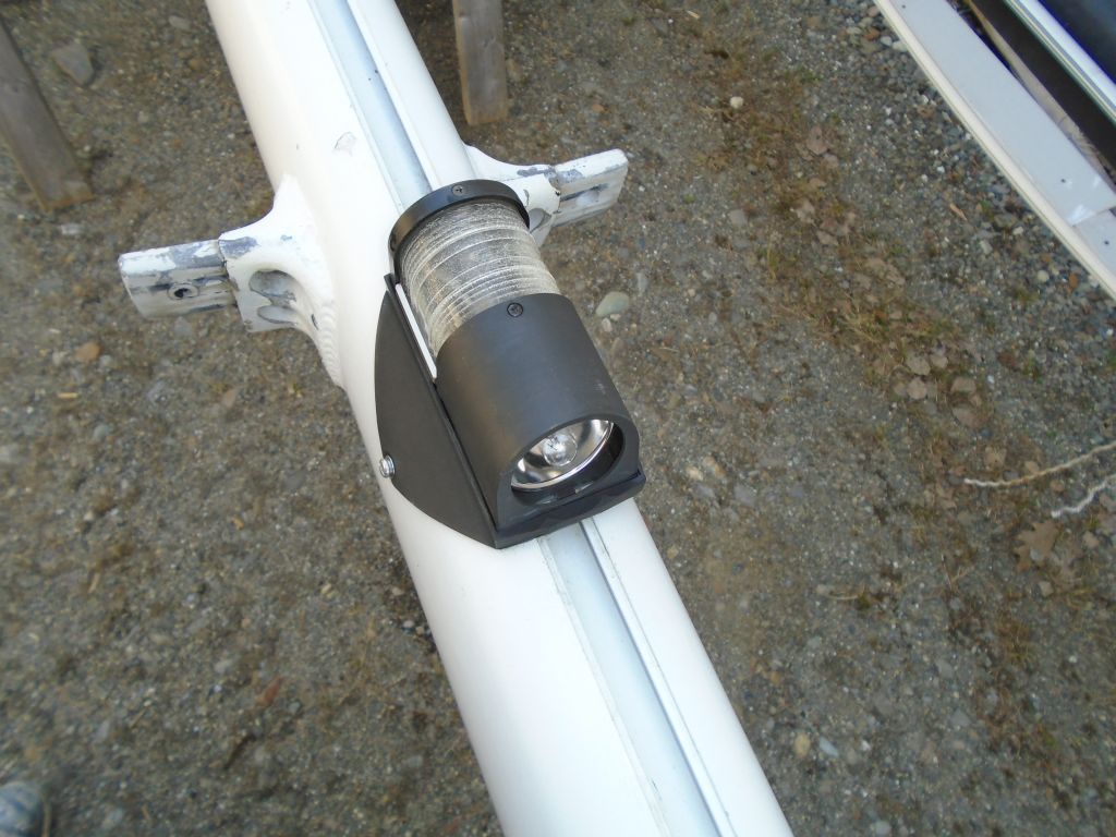
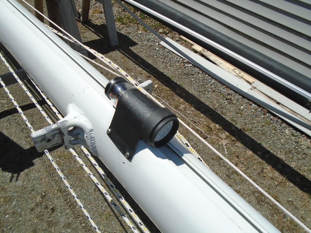
Since it was straightforward to slip on the wire conduit afterwards, I went ahead and ran in the 14/3 wire for the steaming/deck light combo at the spreaders, and made up the wiring at the new LED fixture before installing the fixture with machine screws.  I left some wire slack bundled behind the fixture.

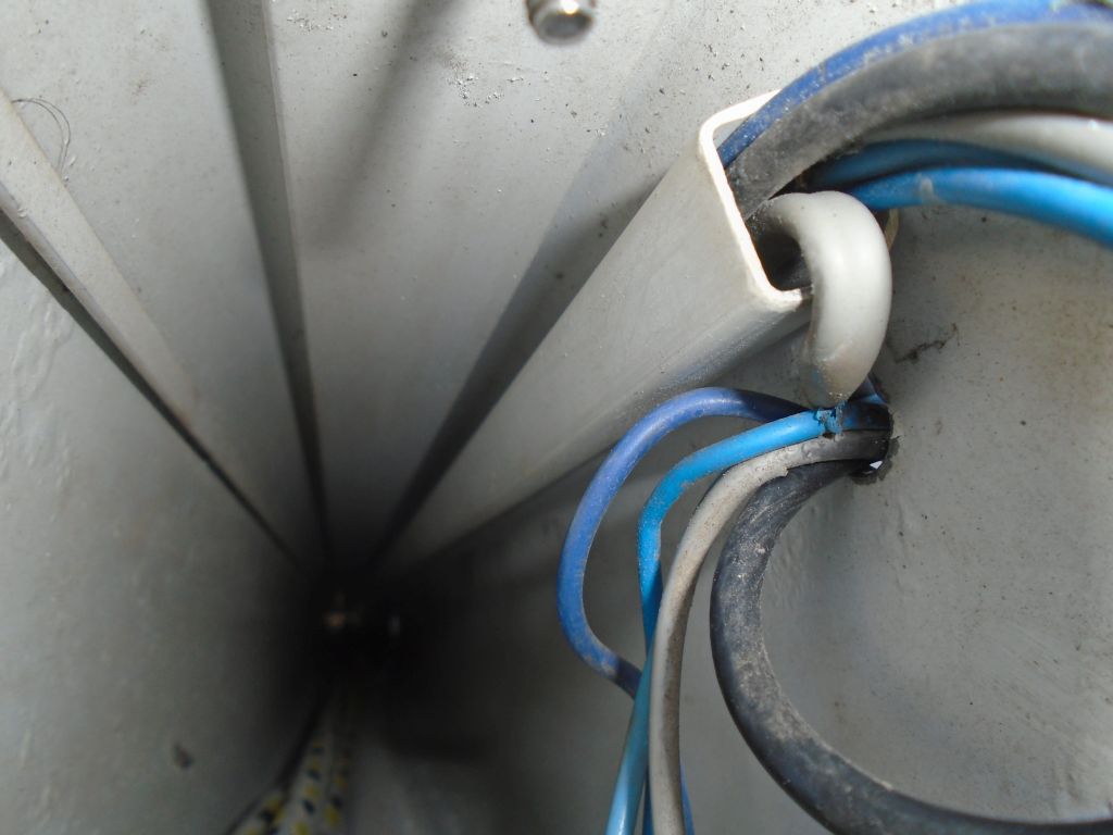
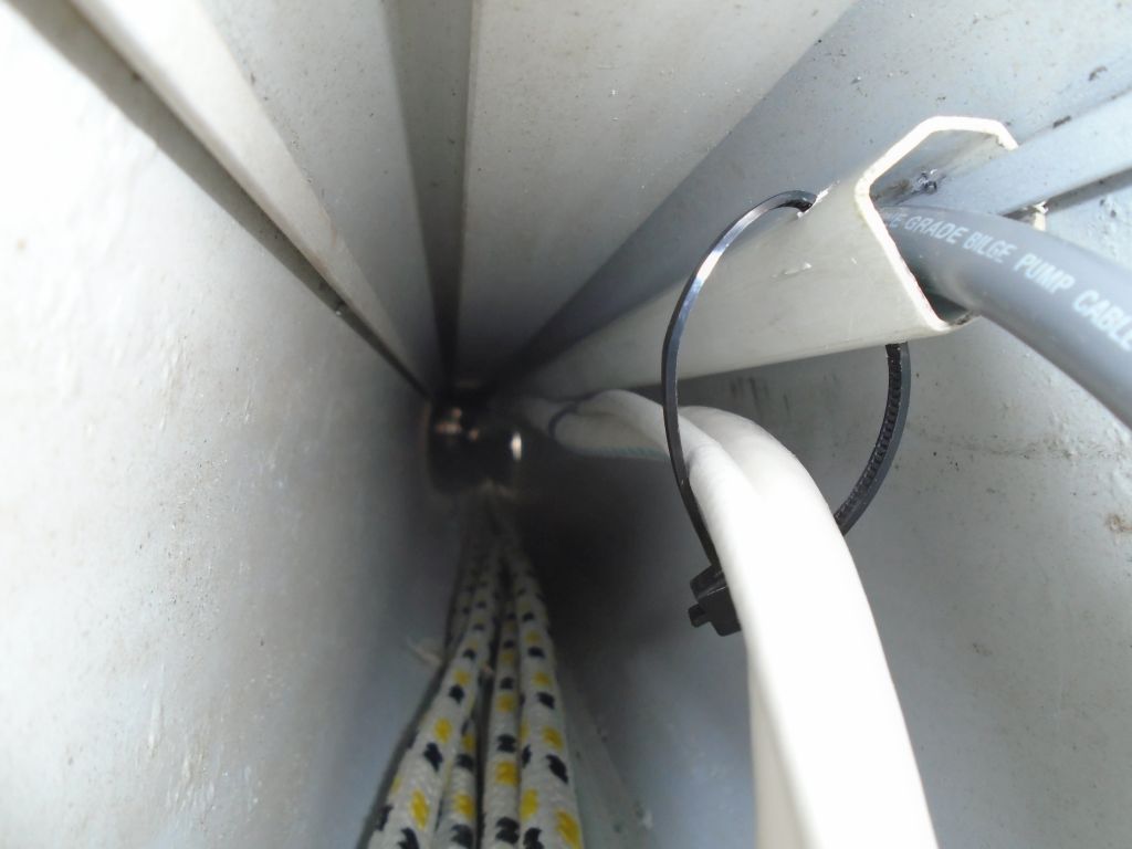
The masthead cable was too large to fit within the internal mast conduit along with the steaming light harness, so to secure it as much as possible I came up with a plan to secure it to the outside of the conduit with cable ties.  With the conduit out of the mast, at intervals I drilled holes at the outer edge to accept wire ties, and as I fed the conduit back into the mast and over the steaming light cable, I secured the thick masthead cable loosely in the wire ties–loose because they had to allow the conduit to slide up, while still securing the exterior cable tightly enough.  This actually worked better than I’d hoped.

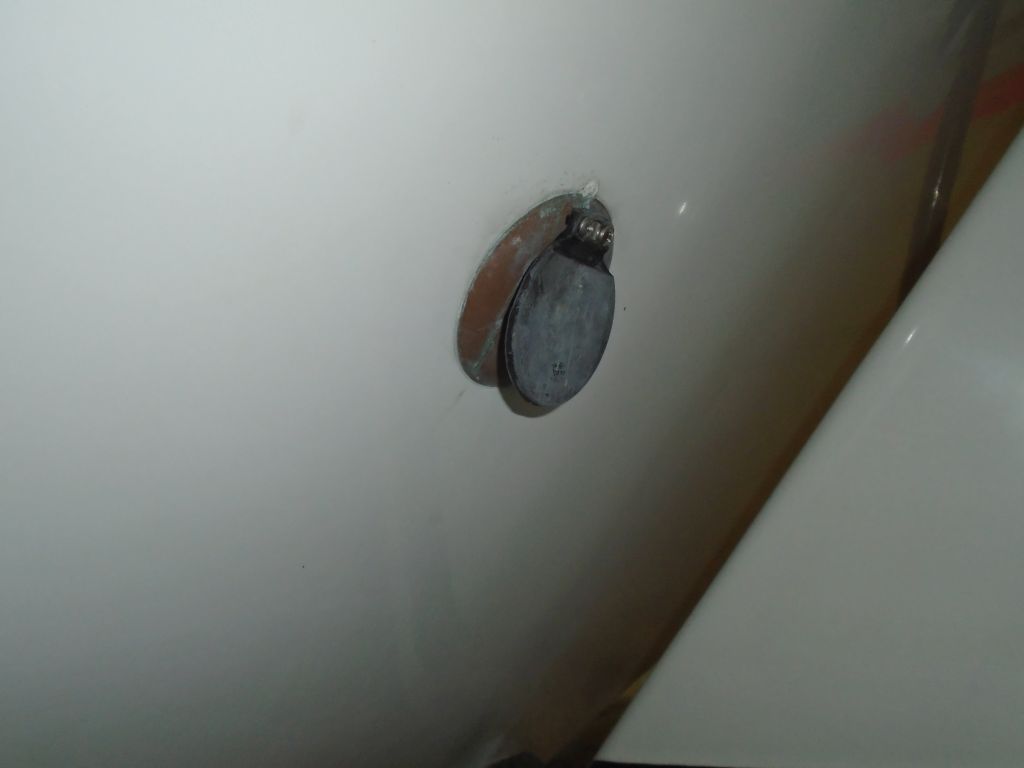
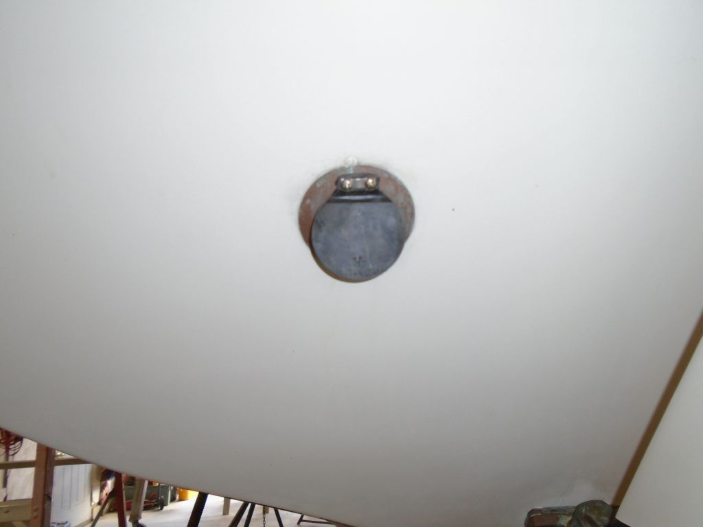
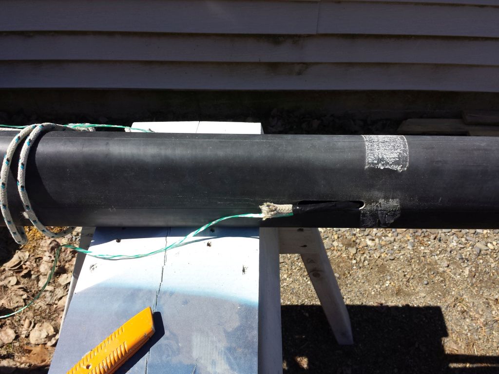
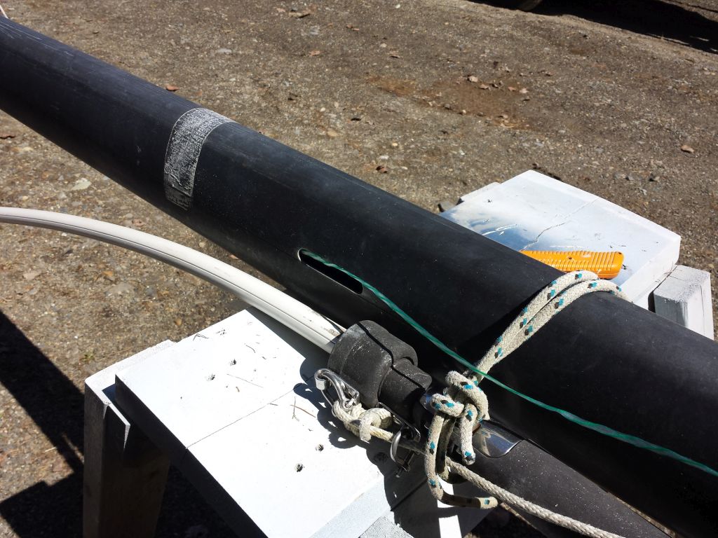
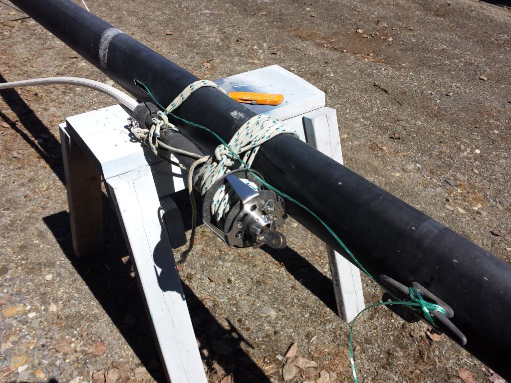
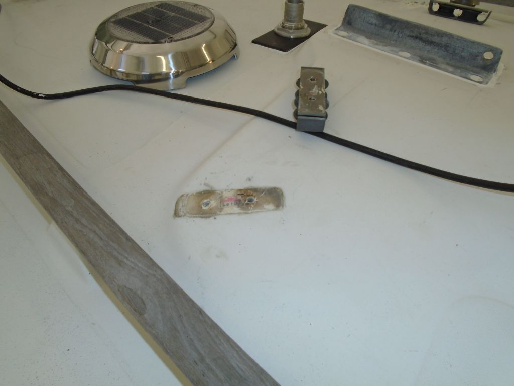
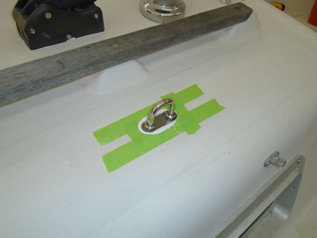
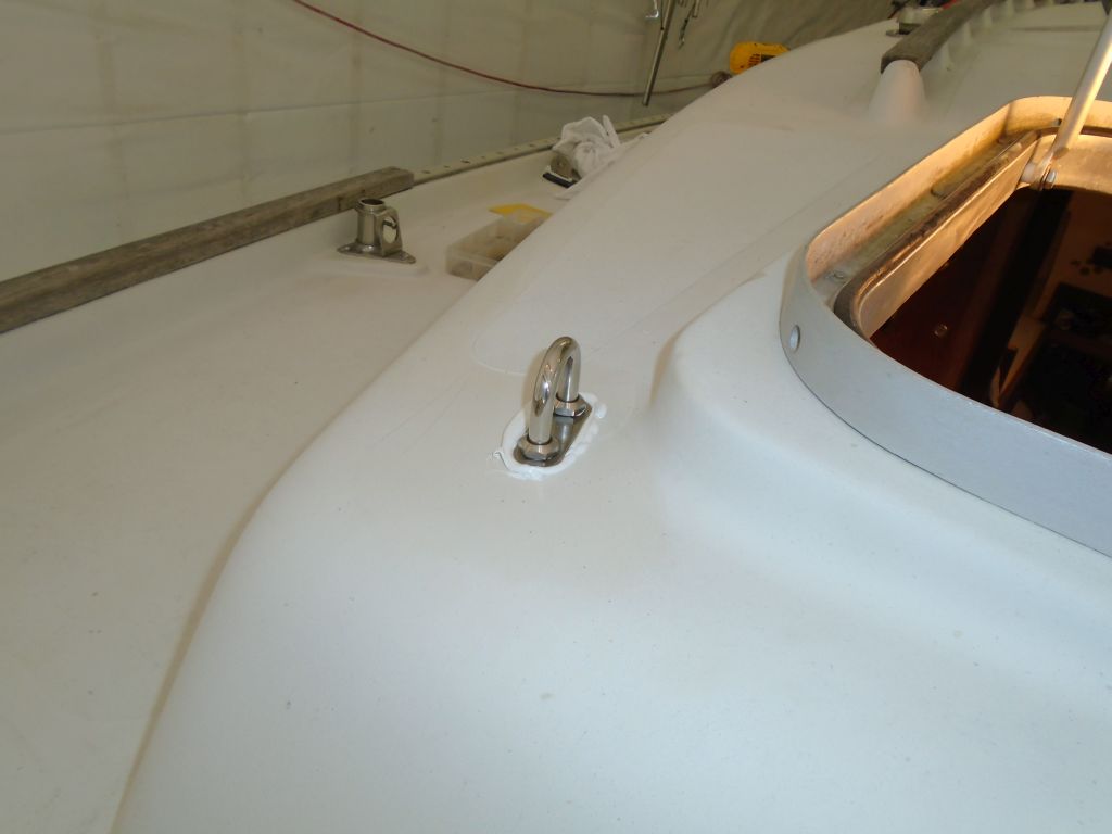
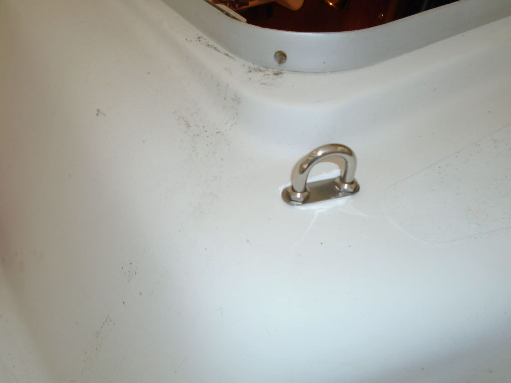
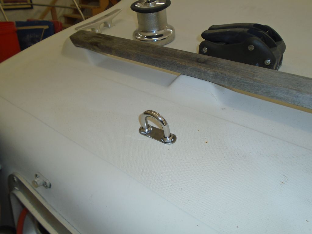
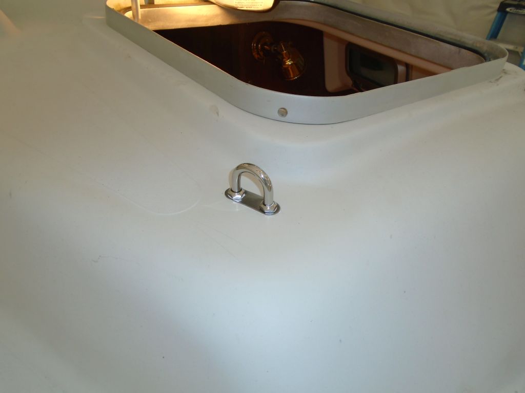
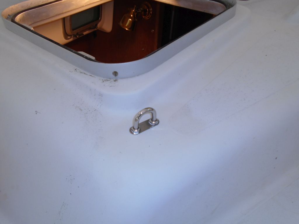
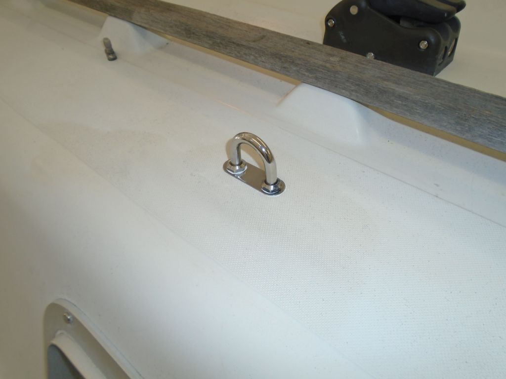
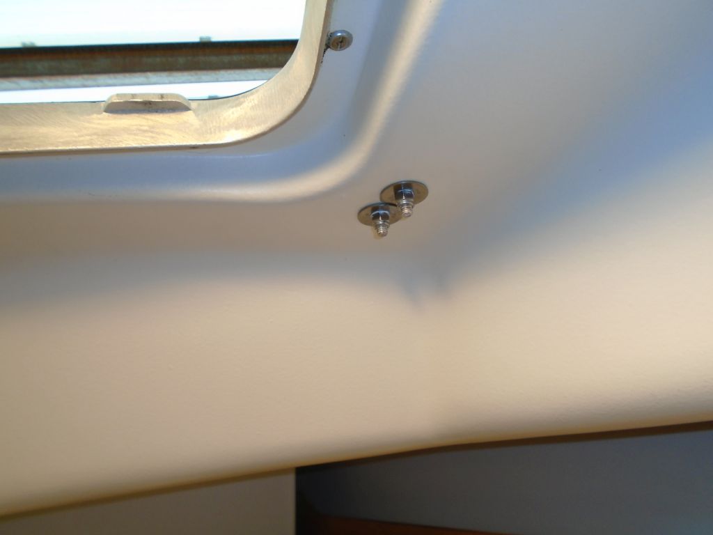
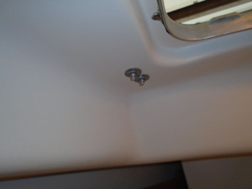
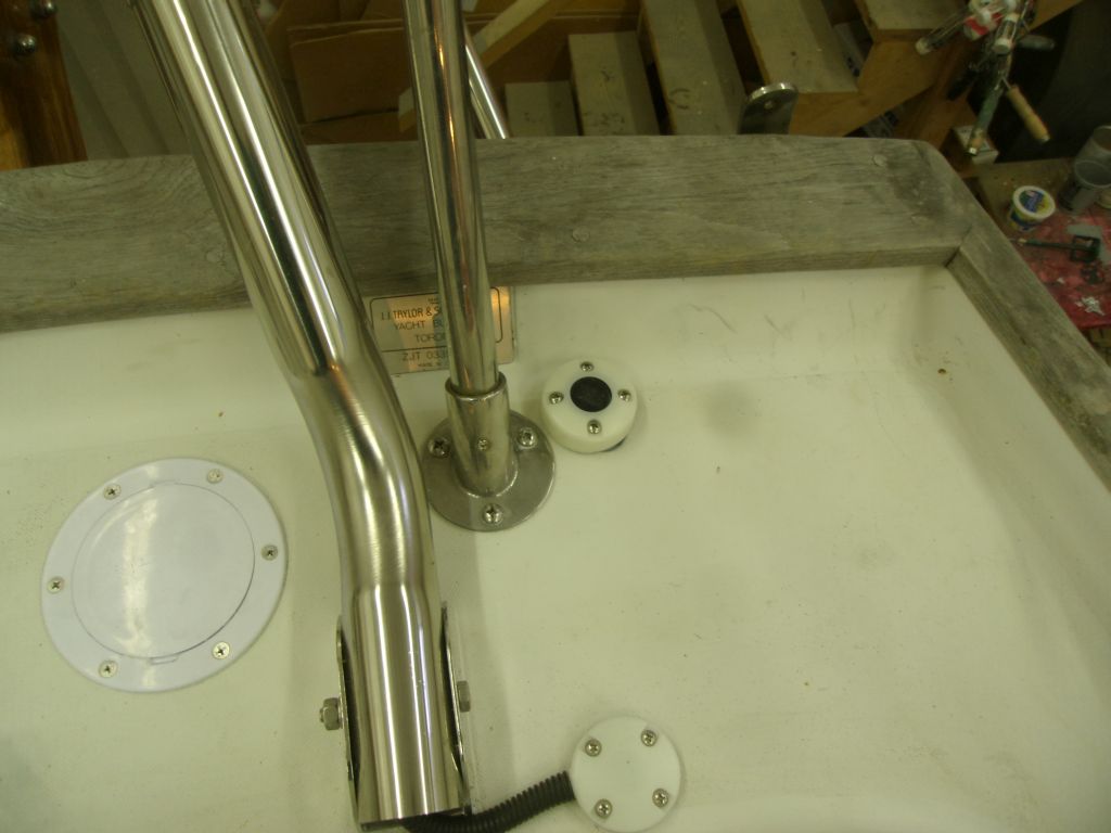
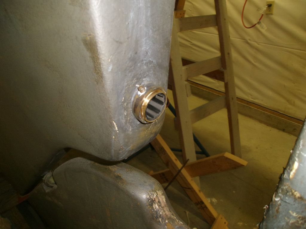
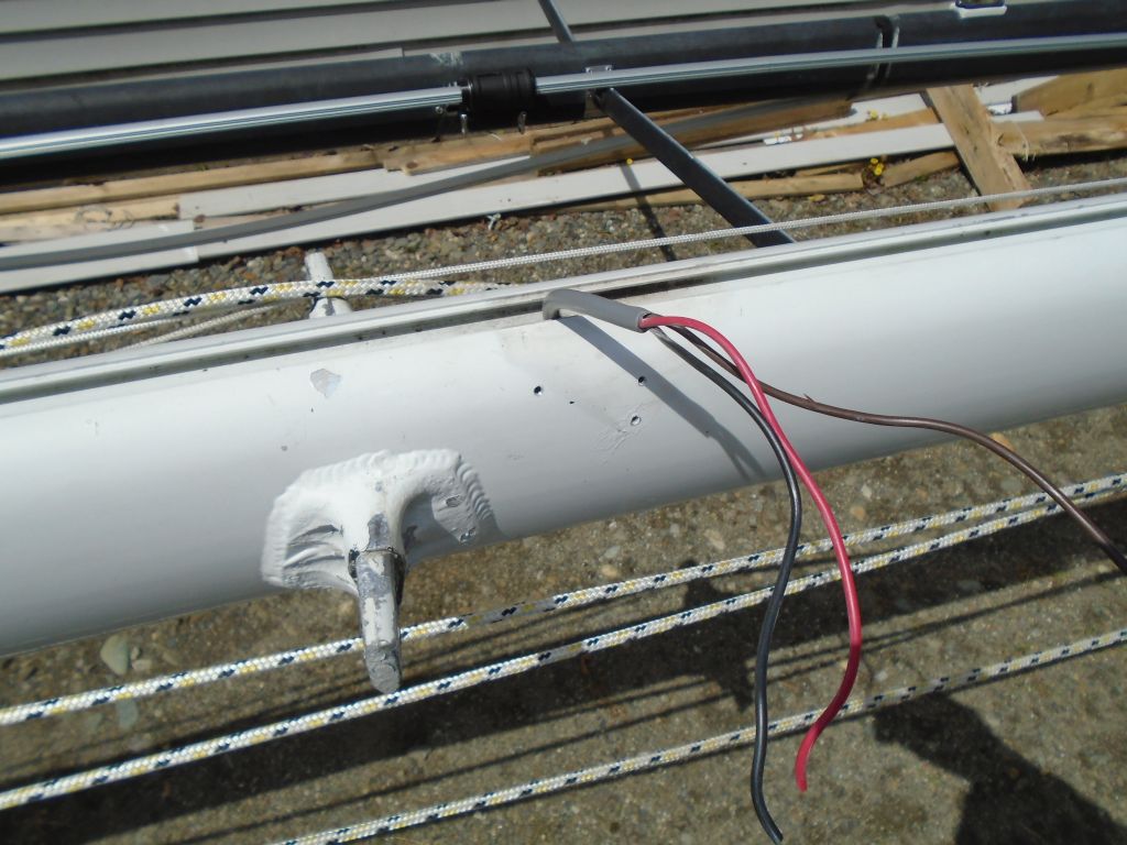
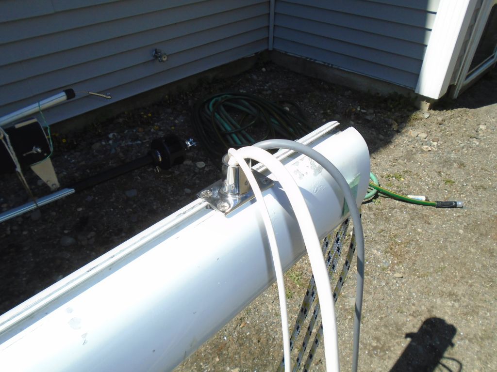
I chose a location on the forward side of the mast for the wire outlet, which would eventually connect (via flexible conduit aka hose) with the deck fitting on the boat.  I drilled a hole for the wires to pass through and installed a rail mount base on the outside, which diameter matched that of the deck fitting (and hose).  Then I led through the wires.

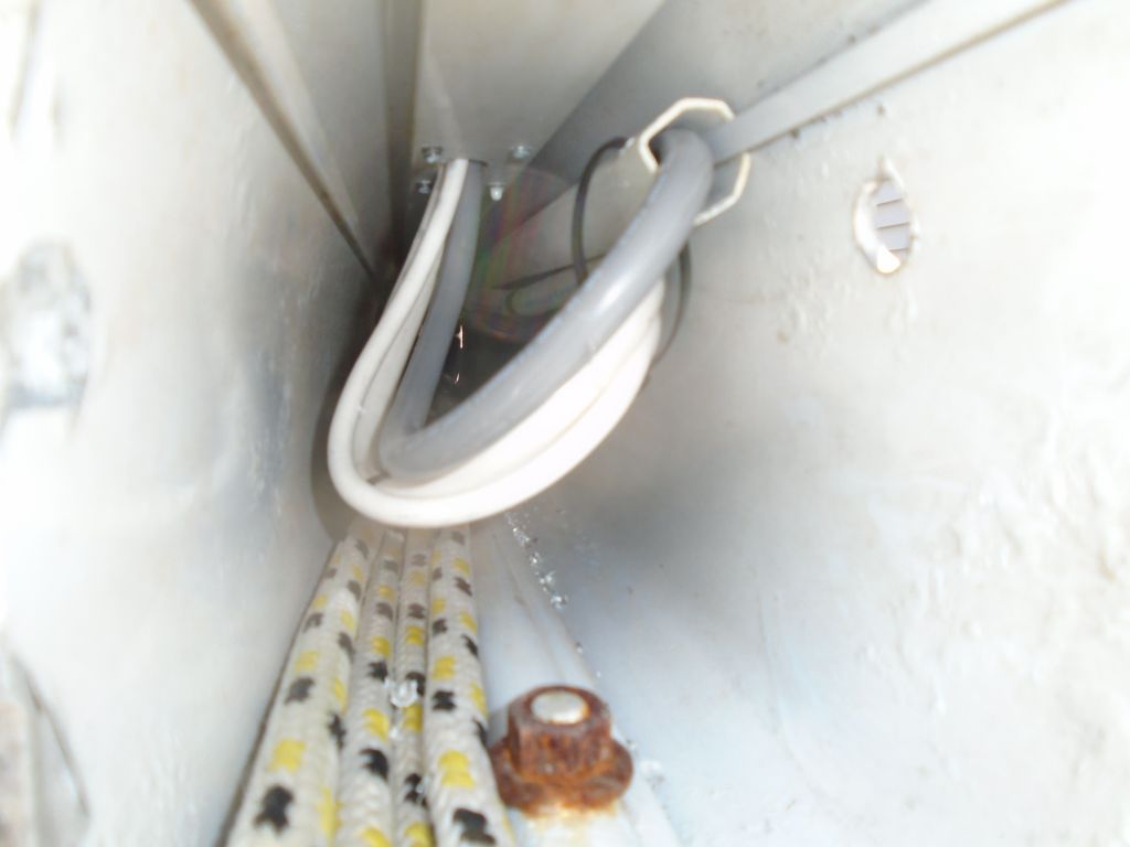
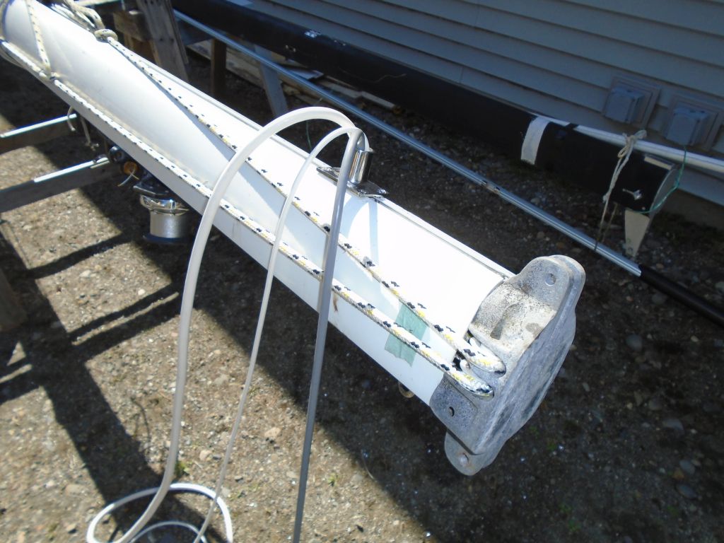
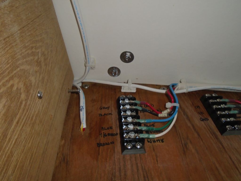
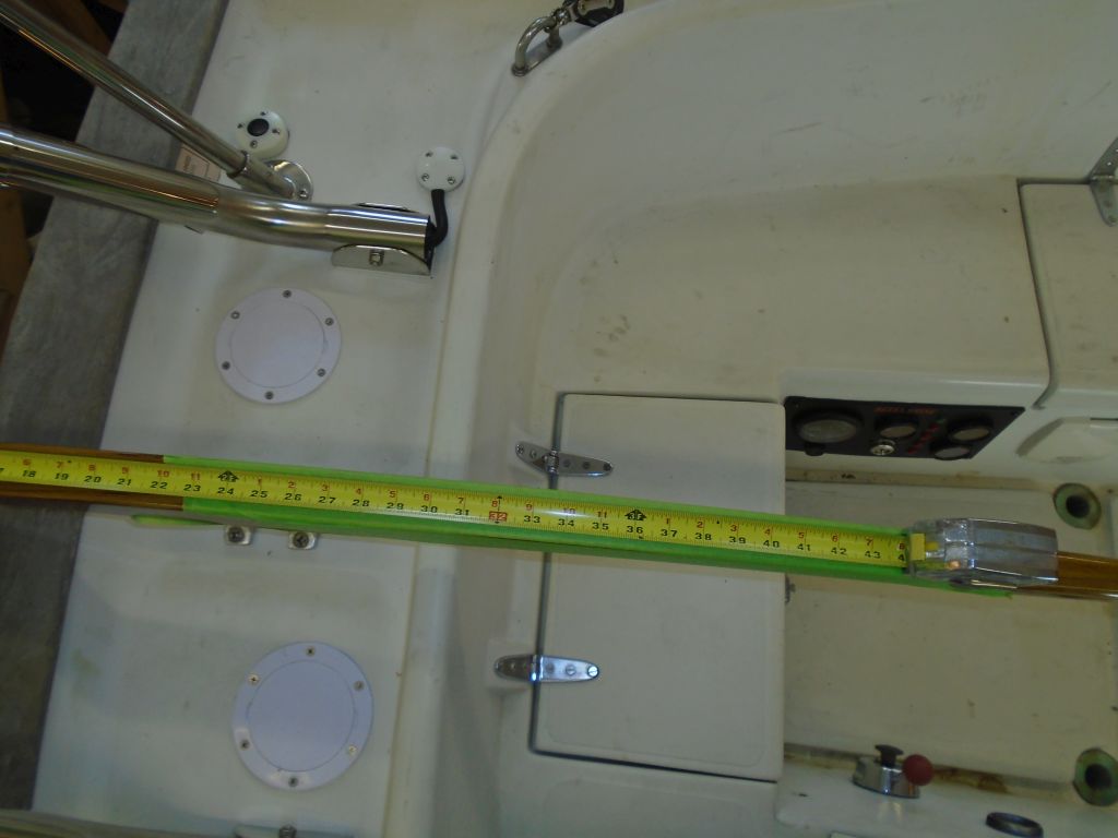
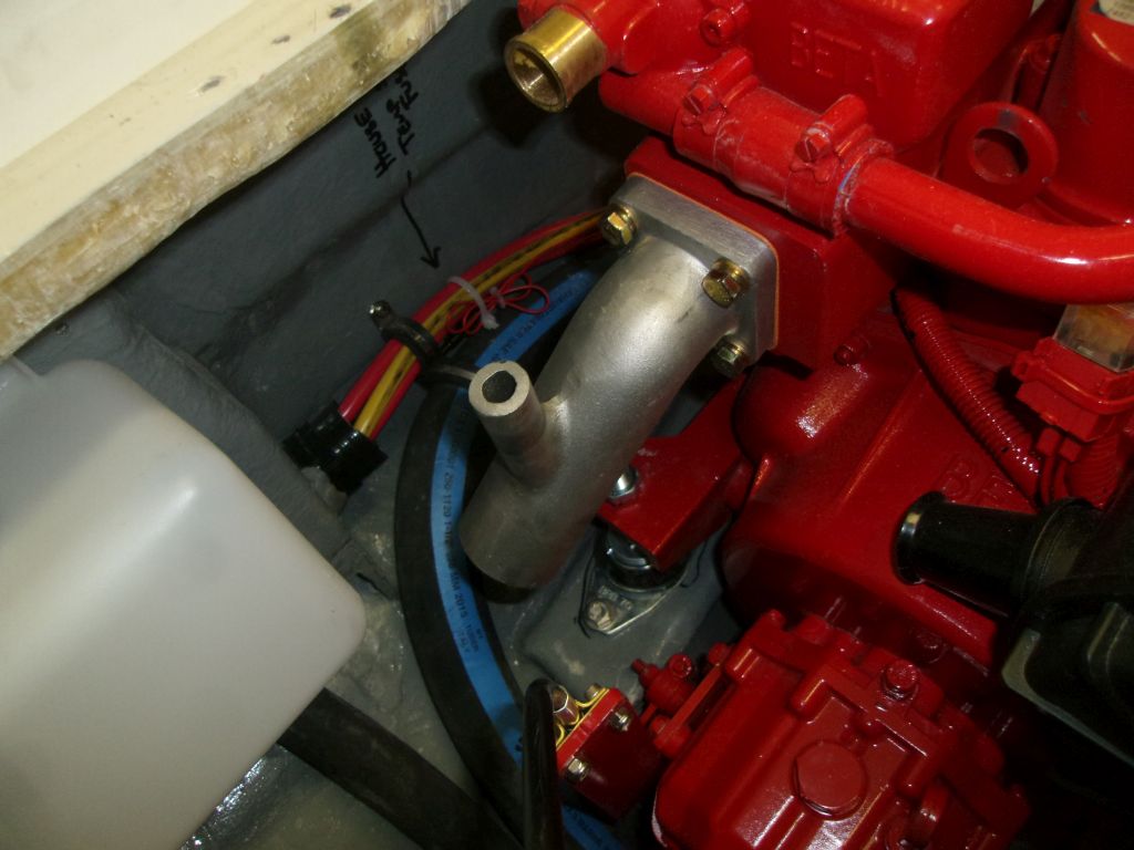
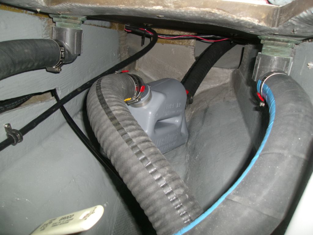
After reinstalling the mast base casting, I measured generously for the final wire lengths, which had to pass through a length of hose/conduit, then through a path in the boat to the terminal blocks for final connection.  Since the terminal blocks were hidden from normal view, and because I wouldn’t be there to make up the wire lengths when the boat was rigged, I left what I thought (and hoped) was more than ample wire length to make up the connections without being ridiculously long.  The wires could always be shortened later if necessary, but at least they were ready to be connected as is.  I labeled the wires as necessary to match up with their respective connections in the boat.

Total time billed on this job today:  5.25 hours

0600 Weather Observation:
35°, clear.  Forecast for the day:  sunny, 50s

Salty 43

< Back to Salty

Tuesday

I spent the morning taking care of myriad smaller tasks, starting with the engine hatch, which I lightly sanded and painted with the finish coat.

enghatch1-41916

I installed a new bulb gasket around the perimeter of the engine hatch.

enghatch2-41916

I cleaned up the original bronze stuffing box, and packed it with two layers of new graphite packing.  There simply wasn’t room to thread on the nut if I added a third layer, though I tried several times to make it work.  After repacking the box and compressing the packing using an old shaft, I installed the stuffing box in the boat with new hose and clamps.

To support and secure the RTE to the masthead, I installed a standard 1″ antenna base, to which the RTE would thread.  I installed it over an existing wire hole in the masthead casting.

mast1-41916

To extend the VHF antenna aft, away from the RTE, I installed an aluminum extension, which I bent to match the angle of the masthead casting so the protruding end would remain level.  I left the extension oversize at the beginning, but later I determined where to mount the VHF antenna bracket and cut off the excess.  The extension could be removed to allow the backstay toggle to be inserted into the mast beneath it, once the masthead casting was back in place.

The topsides featured original gelcoat in good condition for its age, but with some staining, dirt, and oxidation.

It didn’t take much to bring back the shine and clean up the surface with light polish.

The engine exhaust outlet was located fairly high on the transom, above any normal levels of submersion, and this, along with the high cast iron gooseneck just inside the transom, would be as effective as anything against potential backflow into the outlet. The very space available in the boat required certain compromises in the exhaust system design.  However, to ward off a following sea in more extreme conditions, the owner elected to add a simple exhaust flap over the outlet, which added a bit of extra protection to the system.

Total time billed on this job today:  6.25 hours

0600 Weather Observation:
40°, light rain.  Forecast for the day:  Rain ending, clouds, 50s

Salty 42

< Back to Salty

Monday

To finish up the basics of the Monitor windvane installation, I installed a pair of small cheek blocks on the coaming, locating them near the initial layout marks I’d made, but adjusting as needed to where they made the most sense and the fairest lead to the vane and to the tiller.

The blocks’ positions allowed me to finalize the installation for the two cam cleats on the underside of the tiller.  I left the lines long for the owner to fine-tune as he saw fit.  Afterwards, I lightly polished the coaming and aft deck to complete the areas I’d not done the last time.

Next on the agenda was the bottom, which required sanding prep before converting to a different type of paint, so I removed the staging for better access and prepared the boat by covering the decks with plastic sheeting to keep dust off and out of the boat.  Before beginning further work, I polished the hull right at the waterline so that later I’d not run into the new paint.  I’d do the rest of the hull later.

bottom1-41816

Afterwards, I sanded the bottom to scuff up the surface–the existing was a teflon-based paint that was compatible beneath the new paint the owner chose, but required sanding first.  I didn’t attempt to remove the paint, but just scuffed it thoroughly to ensure good adhesion.  Once complete, I cleaned up and solvent-washed the bottom.

Next, after masking off I applied two coats of red antifouling paint.

Earlier, I’d determined a requirement for some additional wiring for the mast–I’d need to extend the 5-wire harness for  the radar target enhancer (RTE) since the wire provided with the unit was far too short, a shortfall I’d fortunately discovered before it became critical.  The owner and I had also discussed VHF antenna placement to avoid interference and physical contact with the RTE, and came up with a plan that would require some additional material as well.  So while I waited for the new wire and other material to arrive, I thought I’d see what I was in for with the mast project.  I found that both the top and bottom castings of the mast were removable, which greatly helped access within, so that was a plus.  Inside the mast, running up at least as high (but possibly not beyond) the steaming/deck light combo at the spreaders, was a plastic conduit containing the old wires.

I’d begin the mast work soon, but for now I just removed the old steaming light, as there was a new replacement on hand.

Total time billed on this job today:  6.25 hours

0600 Weather Observation:
40°, clouds.  Forecast for the day:  Mostly cloudy, 50s, showers late

Precision 1

< Back to Precision 23

Saturday

Preparing for the work ahead, a few days earlier I’d removed the winter cover and frame, which gave my upholstery contractor access to the interior so he could prepare a quote and measurement for new cushions that the owner requested.  Meanwhile, I removed the mast down to the ground for storage and minor work, and removed the two halyards so I could ship them–and the boat’s lifelines–off to a rigger for replacement.  I led messenger lines through the mast as I removed the halyards.

Now, with the project ready to begin soon and shop space available, I moved her indoors.

Total time billed on this job today:  1 hour

0600 Weather Observation:
30°, clear.  Forecast for the day:  Breezy, sunny, high in the 50s

Aquasport 4

< Back to Aquasport

Saturday

I’ve never entirely trusted outboards–with ample reason born from experience–and last season a fuel problem left me inconvenienced, though certainly not endangered.  So I decided to add a kicker bracket so I  could have get-home power if required.

I chose the port side of the transom for the installation and, following the instructions, I determined the mounting height of the bracket and marked the hull accordingly.   Knowing the transom was cored, I bored out the fastener hole locations with a 1″ bit to remove core, which turned out to be some sort of foam, possibly Airex.  Then, I filled the voids with thickened epoxy.  When the time came to install the bracket, the 3/8″ bolts could pass through the center of the epoxy-filled area, thus obviating any chance of water leakage into the core.

The layout process highlighted an issue with the boat and bracket:  the bracket handle interfered with the gunwale assembly, so the bracket wouldn’t operate properly as is.  I’d have to add blocking beneath the bracket to keep it clear of the gunwale, and determined I needed a full 1-1/2″.  I thought of using some leftover teak that I had on hand, but decided instead to build the block from two layers of 3/4″ fiberglass sheeting, which I glued and clamped together with epoxy.

bracket4-41616

I’d complete the bracket installation later, once the backing block was ready, the epoxy plugs were cured, and I had the proper fasteners on hand.

Meanwhile, with new registration numbers now on hand, I installed them, a nice improvement over the old hardware store stick-on letters.

With no further need for the boat indoors, I moved it out to make room for another project.  I liked the new appearance and felt it made a significant different to the overall feel of the boat, just as I’d hoped.  The devil is in the details.

Total time billed on this job today:  2 hours

0600 Weather Observation:
30°, clear.  Forecast for the day:  Breezy, sunny, high in the 50s


Salty 41

< Back to Salty

Friday

After an overnight cure for the epoxy plug filling the (as it happened) unneeded hole for the starboard turning block, I proceeded with the block’s reinstallation.

To prepare the modified engine hatch for its final paint, I applied a coat of epoxy-based 2-part primer, which would help ensure that the one-part final paint would cure properly over the still-fresh epoxy.  I had enough primer mixed to coat the entire hatch, though it wasn’t really needed.

enghatch1-41516

With most of the work done in the cabin and no longer any access required forward, I reinstalled the bi-fold head door, and loaded into the forward cabin some of the spare gear and equipment that I’d removed early in the project.

head1-41516

The original light gray gelcoat on the deck (and hull, come to that) was in good overall condition considering its age, but was dirty and oxidized, which didn’t enhance its appearance.

To clean it up and restore shine, I used a light polish on the smooth surfaces, which had a good effect on the gelcoat.  These three photos attempt to show the work in progress, though there’s not enough contrast in the photos to see it properly.

In a couple hours’ work, I polished all the deck areas except the cockpit well (which I’d do a little later, once I was done with work on the engine) and a portion of the after deck, which was cluttered with tools and the ongoing Monitor windvane line installation.

With the required connector now on hand I could finish up the VHF antenna cable installation, after which I could reinstall the backrests in the cabin, since I no longer needed access behind the electronics panel.

Now that deck work was complete, I reinstalled the lifelines, which I’d removed for storage and for the duration of the project.

Total time billed on this job today:  5.75 hours

0600 Weather Observation:
26°, clear.  Forecast for the day:  Sunny, low 50s

Salty 40

< Back to Salty

Thursday

Starting with the halyard winches and rope clutches at the after end, I removed the final pieces of deck hardware from the coachroof so I could rebed them and replace the fasteners.  I removed the old sealant from the deck and the bases of the hardware as needed.

The deck here was not cored, so I could proceed directly with reinstallation.  I masked off the deck around the footprints of the hardware, and reinstalled with sealant and new fasteners.

Near the mast step was a pair of turning blocks to run the halyards aft, and these were the last pieces to remove and rebed.  After removing the blocks, the fasteners looked so long that I figured there must be a core in that part of the deck, so I drilled out one of the fastener holes with a 1/2″ bit.  However, there was no core–it was just a thick solid area, presumably part of the built-in reinforcement for the deck-stepped mast.  So I filled the erroneous hole with thickened epoxy, but I’d have to wait to install the starboard turning block till later.

There was no stopping the progress on the port side, however, where I cleaned up from the old installation and reinstalled the block with new fasteners.

I’d decided to replace all four lifeline tether padeyes on the cabin top, as it just seemed right given their function, and the replacement hardware was inexpensive.  So with new padeyes on hand, I installed the four with new sealant and large washers.  I’d come back later and cut off the excess bolt length beneath.

To smoothly fair the lobster pot batten into the keel, now that it was well-secured I applied some additional epoxy to fair its transition to the bottom of the keel.

lobster1-41316


Total time billed on this job today:  5 hours

0600 Weather Observation:
30°, clear.  Forecast for the day:  sunny, 50

Salty 39

< Back to Salty

Wednesday

To determine what sort of hardware was required to run the pendulum lines from the  Monitor windvane, I mocked up the two lines, using the supplied instructions as a guide.  With tiller steering, the lines must cross when the leave the vane, so I led the lines to the opposite sides accordingly.

The guidance suggested that the lines should attach to the tiller approximately 30″ forward of the rudder post, so with protective masking tape covering the tiller (and the coaming surfaces, for marking purposes), I measured this distance, which ended up right over the aft coaming.

The instructions suggested that the control line should lead at right angles to the tiller when the tiller was turned 15° to the side, so I made marks on the coaming when the tiller was at this angle, and used a square to roughly locate the turning blocks’ locations on the coamings.  The design of the coamings, and the way the lines led forward from the vane, limited the realistic options for block placement, so I adjusted the proposed tiller mounting location forward as needed (about 3″ or more forward of the 30″ mark) in order to achieve close to the desired 90° angle for the control line from the tiller to the coaming block.

The tiller attachment kit included two cam cleats to mount on the underside of the tiller.  With the design of the tiller, and how it related to the coamings as it turned, this was a second reason the attachment point needed to move forward, as the cleats would interfere with the coaming if mounted any further aft.

Of course the tiller could be lifted for additional clearance beyond this point, but mounting the cleats any further aft would likely interfere with normal use of the tiller both on and off the windvane.

monitor14-41316

In the end, this arrangement looked like it should work well, and at least allowed me to order a pair of cheek blocks to mount on the coamings.  The proposed leads were straight and fair, and with the minor adjustments to the ideals suggested by the manual, fulfilled all basic requirements.  I took the time to check with Scanmar, manufacturer of the windvane, about any repercussions from locating the tiller attachment further forward, and  the answer was that this increased leverage on the tiller–not a bad thing–and there didn’t seem to be any negatives given the overall installation situation.  The reality was that there wasn’t much for other options anyway, but it was good to know that the minor adjustments required wouldn’t negatively impact the performance.

After an appointment away from the shop during the mid-morning, I got back to things with the engine hatch.  The clearance above two sections of the engine–the secondary fuel filter and part of the cooling system–was tight enough that I decided to omit the hatch coring in those two areas.  I hoped that final alignment adjustments on the engine would actually lower the front of the engine, increasing this clearance, but I couldn’t be sure, and if I had to raise the engine at all, clearance could become an issue.  So after marking the rough perimeters of the areas in question, down on the bench I cut out the coring from these areas, then sealed the exposed core and created fillets with thickened epoxy around the edges of the cutouts.

enghatch1-41316

While I had the epoxy  going, I quickly prepared the bottom edge of the aft side if the keel and installed a slim fiberglass batten to extend aft beyond the slot formed by the rudder and keel.  This batten would help any lines that one might run over to slip aft cleanly, and reduce or minimize the chance that they might get hooked in that open slot before the rudder.  I taped the batten in place while the epoxy cured.

lobster1-41316

With the owner’s new  VHF radio now on hand, I could move forward with the final installation on the new electronics locker panel, along with the recently-arrived stereo control unit.  With minor adjustments that the owner and I had discussed previously, I laid out the cutouts for these two components according to the diagram and mockup I’d worked out a couple weeks prior, then installed the two units to the panel.

With the hinged panel resecured in the boat, I made up the final wiring connections.  I didn’t have an antenna connector on hand for the VHF, so I’d finish that up once I got the new parts required.  Both units had various extra wires that I tied up as well as I could; for the stereo speaker wiring, I installed removable connectors so the whole panel could be removed for storage during the off-season.  I sent the owner some options for mounting the VHF microphone.

I was all set to finish up the plumbing for the engine’s raw water siphon break, which I planned to mount in the cockpit locker.  I removed the supplied valve fitting from the top of the siphon and installed a hose nipple that I could hook into the existing overflow hose that connected with the exhaust gooseneck at the transom, and prepared a hole to communicate between the engine room and cockpit locker for the hose runs.  To my dismay, however, I discovered that the connection on the engine was for a larger hose than I’d thought–1″ versus 3/4″–and the offcuts of 1″ hose that I had on hand weren’t long enough to make the journey required, so I had to halt the project and order enough 1″ hose to do the job.  It seemed to me that these connections were different every time I installed one of these engines–I was sure I’d used 3/4″ hose before, but perhaps my memory was just short.  In any event, final installation, with all the basic preparations made, would be quick once I got the new hose.

siphon1-41316

Total time billed on this job today:  6.25 hours

0600 Weather Observation:
25°, clear.  Forecast for the day:  sunny, around 50

Salty 38

< Back to Salty

Tuesday

The structural work on the modified engine hatch was complete, and after sanding as necessary I test-fit the hatch, which fit as intended.  I ordered longer screws to secure the hatch to the flange beneath.

With most major tasks on the project list either complete or awaiting additional parts, I turned to some of the interior reassembly, starting in the bow, where I reassembled the wire chase cover on the starboard side and the v-berth fiddles, after cleaning up the shelf areas as needed.

In the hanging locker, at the owner’s request, I installed two pair of utility hooks, then reassembled the various interior dividers and covers, as well as the two sections of the outer bulkhead.

Across the way, I installed new vent hoses to replace the originals that I’d removed earlier in the project, and reassembled the cover panel behind the head.  For now, I held off on reinstalling the bifold door till I was sure I didn’t need access.

In the vertical hatch that covered the forward end of the engine room from the cabin, I installed a fire port, a simple ring that allowed use of a fire extinguisher without removing the hatch.  I installed this as high in the hatch as I could to allow easiest access and best effectiveness.

fireport1-41216

To cover the wire chase between the new electronics locker and the electrical panel, I cut off the aft section of the original cover (the forward part was no longer needed) and installed it.

GE

At the forward end of the cockpit, I installed a pair of heavy padeyes for lifeline tethers, bolting them through the bulkhead into the cabin.  I kept these high enough to clear the newly-raised engine hatch.

During my hardware-rebedding phase earlier, I’d stopped after completing all the sidedeck and related hardware so I could focus on the new systems installations, but there were a few items on the coachroof that still required this treatment, and now was a good time to take care of these.  I started by removing four U-bolts–two at each end of the cabin top.  The port after u-bolt featured highly rusted nuts for some reason, and these took some torque to loosen.  I thought I might replace that particular U-bolt; the other three appeared serviceable.

I removed interior covers over the fasteners securing the cabin top winches and line jammers, but would get to their removal another time.

Meanwhile, at the transom I finished up the installation of the two cable clams.

The replacement exhaust elbow arrived, and I installed it and cut the hose to length, completing that installation.   I’d been contemplating how (or whether) I could run a siphon break for the raw water injection line, but completing that would be for another day.  Space and access was at a premium.

Also engine-related, I installed the new Cutless bearing, securing it with two set screws as original (with a dab of sealant in the set screw holes to help hold them).

GE

I planned to lay out the self steering control lines next time so I could order any hardware required, so to prepare for that I installed the tiller.

GE

Total time billed on this job today:  7 hours

0600 Weather Observation:
45°, showers.  Forecast for the day:  showers and rain, high in the 50s

Aquasport 3

< Back to Aquasport

Monday

Now that the boottop primer was dry, I lightly sanded it, then solvent-washed to prepare for the topcoat.  For this, I chose a platinum gray paint that I had on hand from who knows what project, but I thought it would be a nice subtle color for this application.  Actually, the choices in this project were as much about what I had on hand and could use up as they were about final appearance.  The paint covered well, and later in the day I decided that the one coat was ample, so I removed the masking tape, completing the paint work on this boat.

Total time billed on this job today:  .5 hours

0600 Weather Observation:
32°, cloudy.  Forecast for the day:  occasional showers, clouds, high in the 40s

Older posts Newer posts