(page 7 of 27)

Scupper 203

Monday

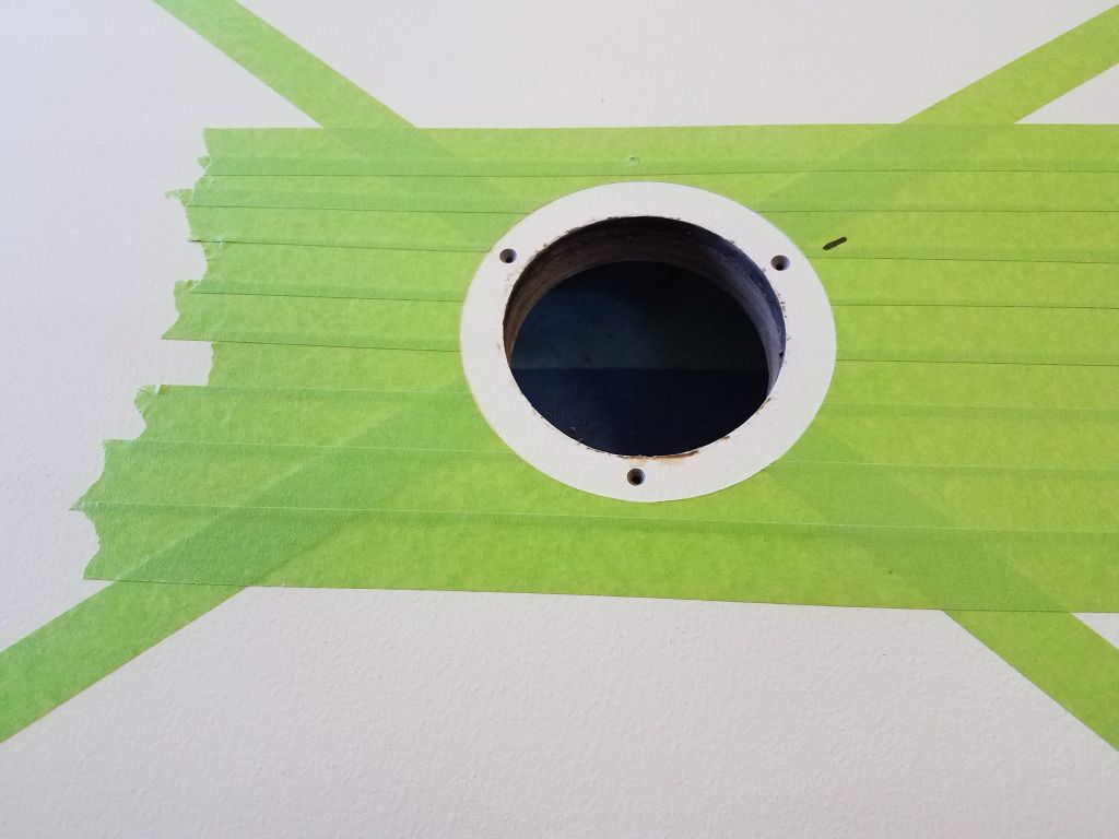
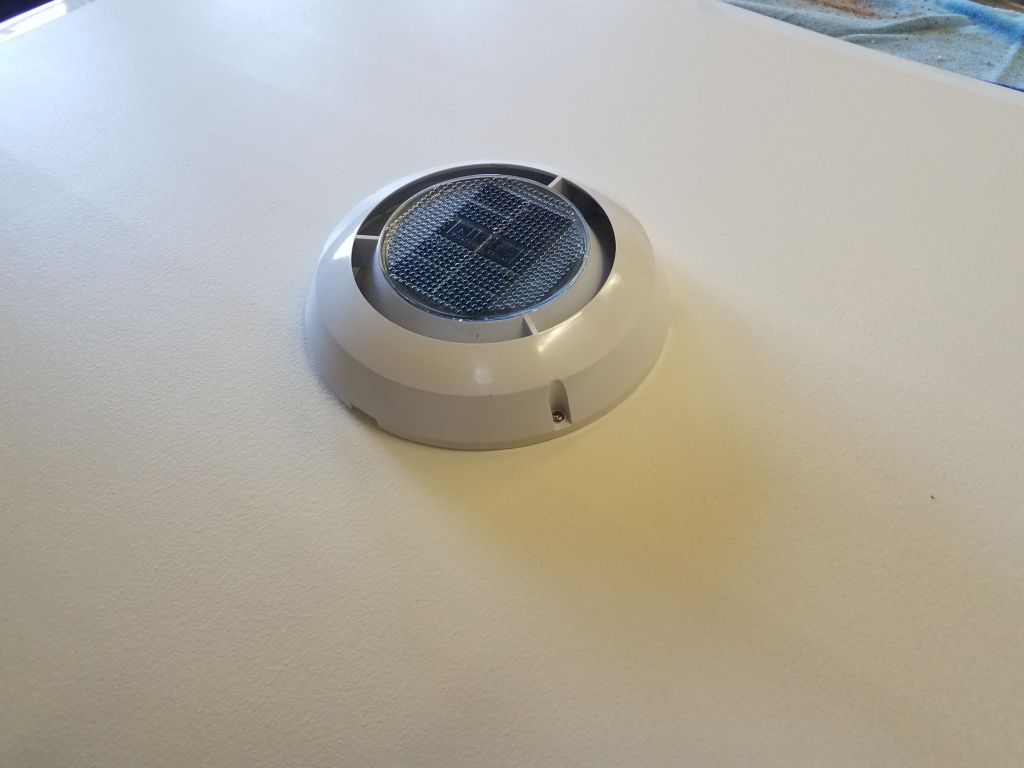
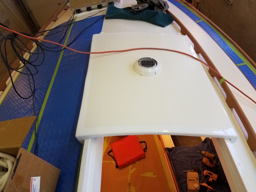
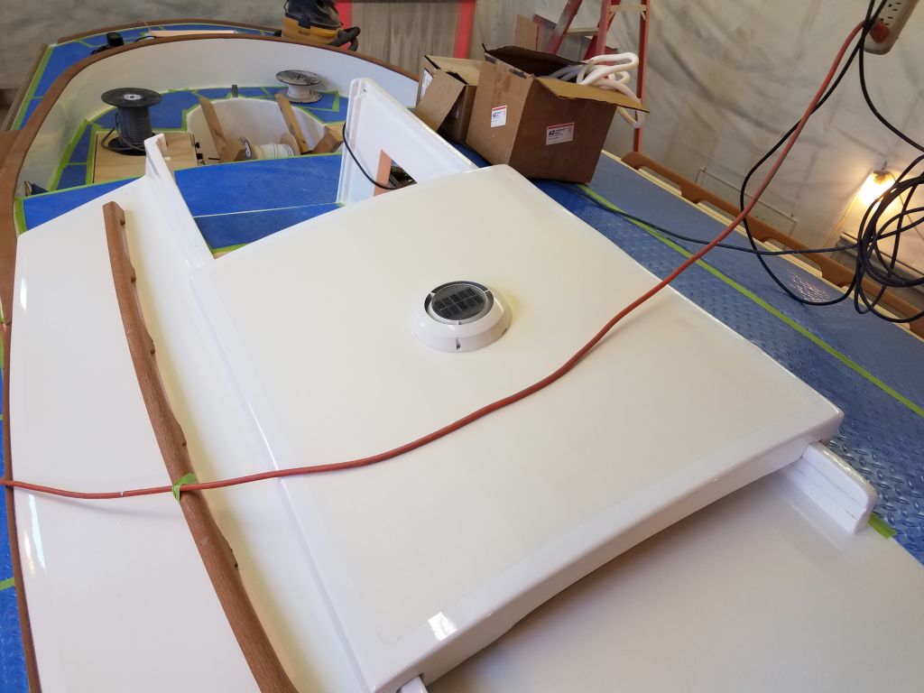
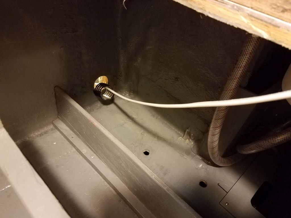
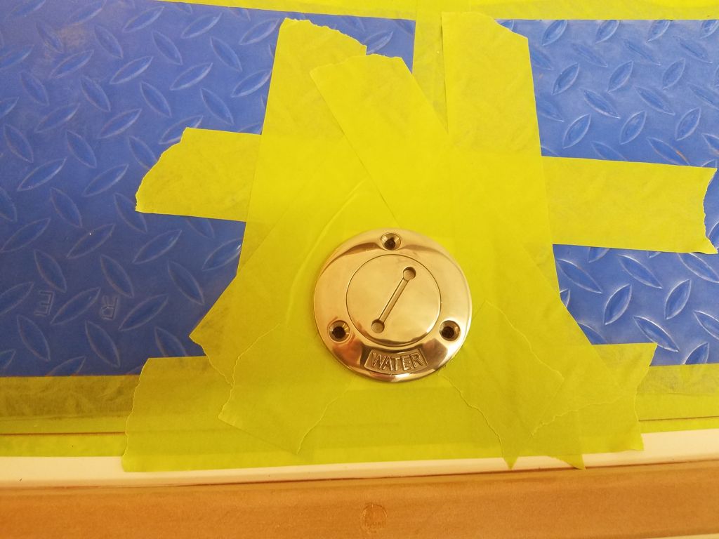
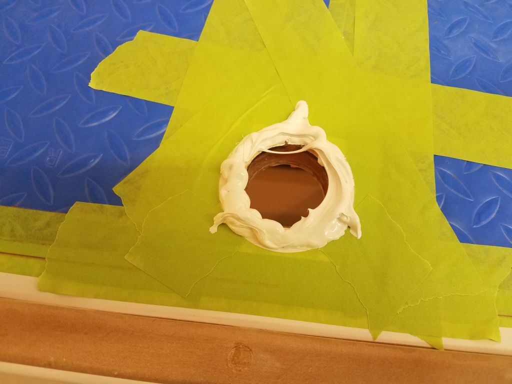
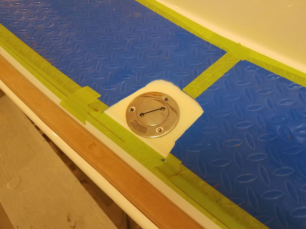
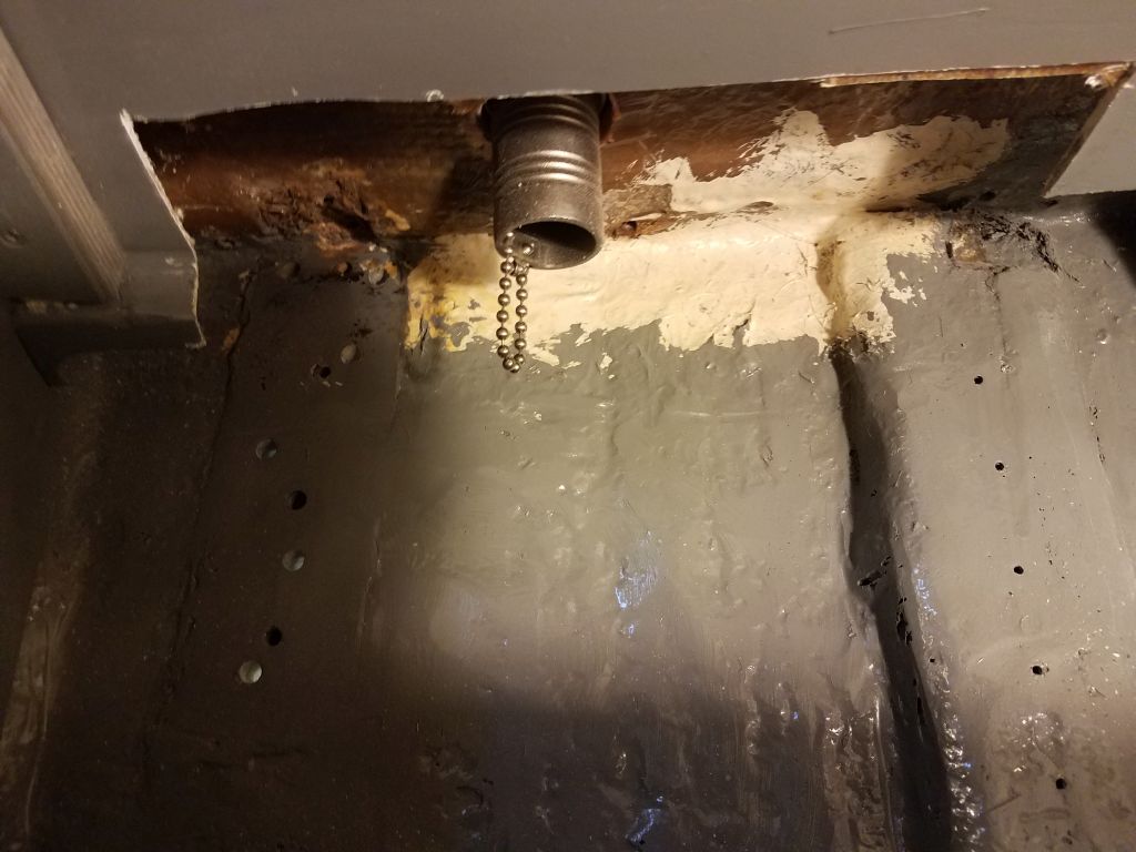
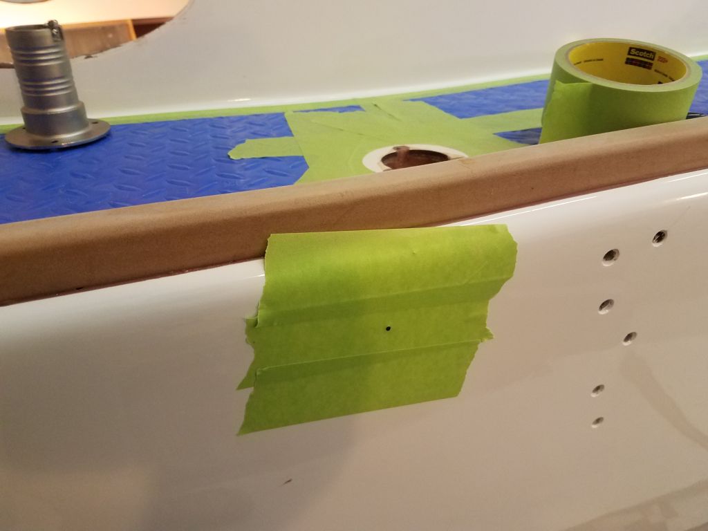
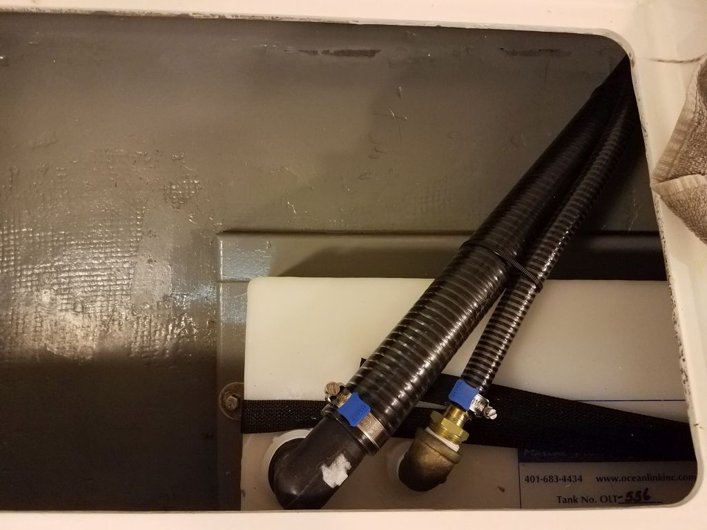
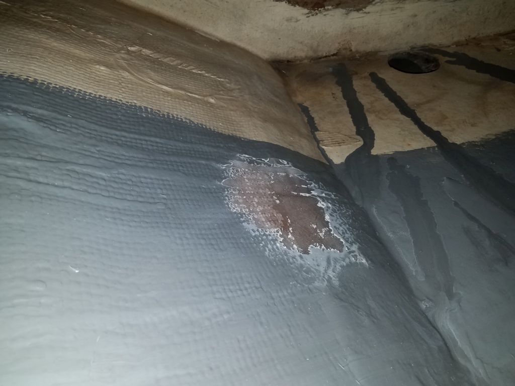
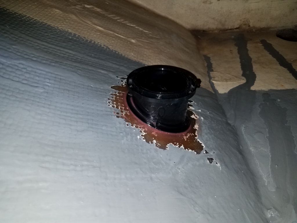
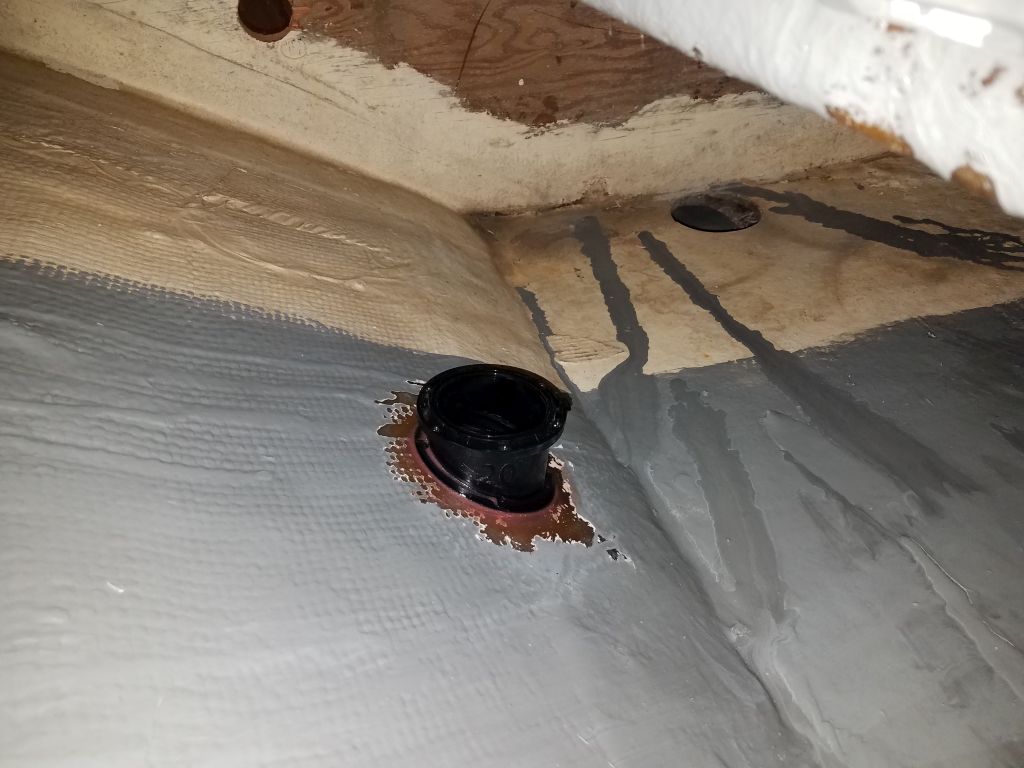
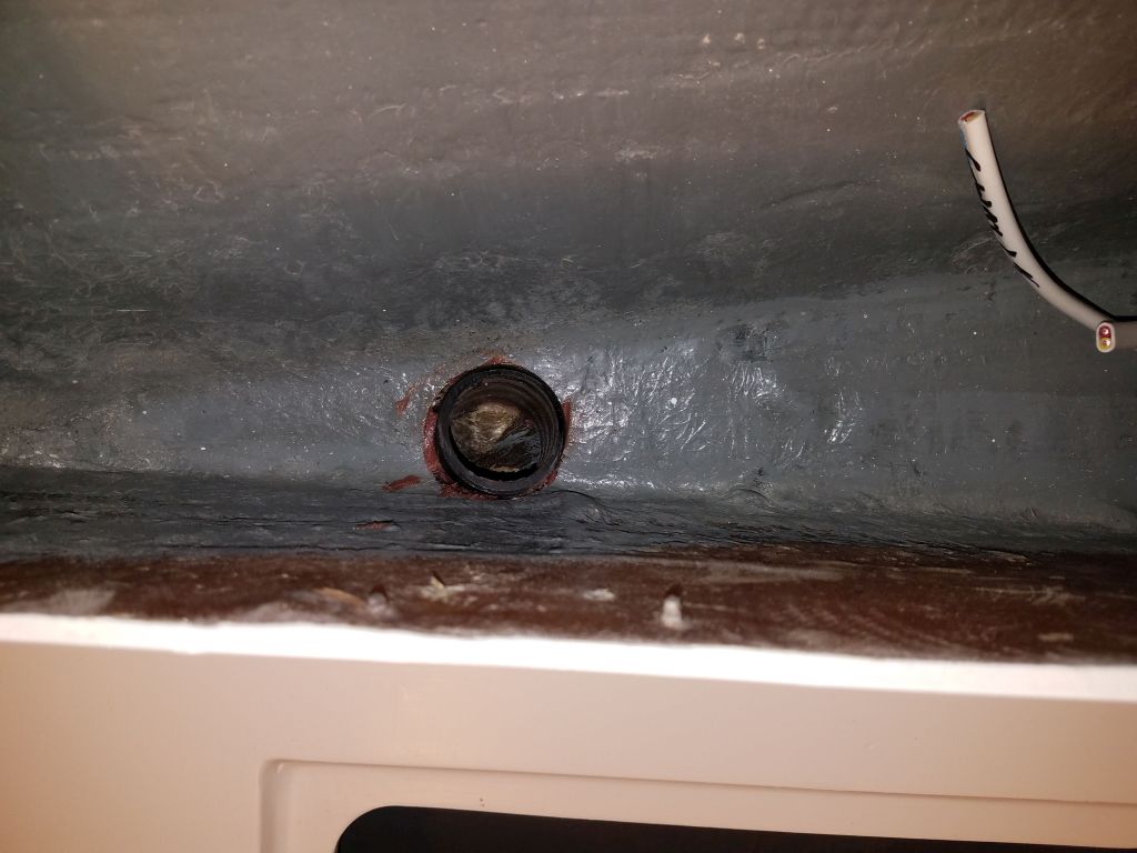
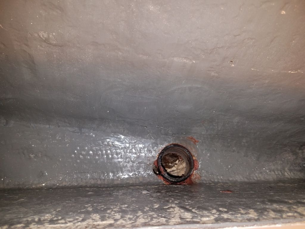
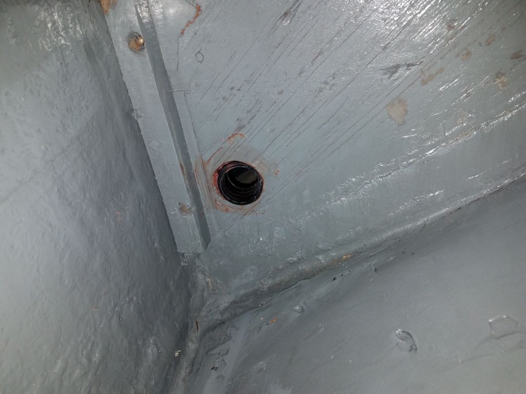
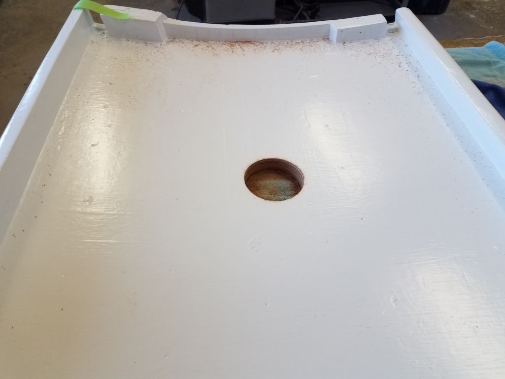
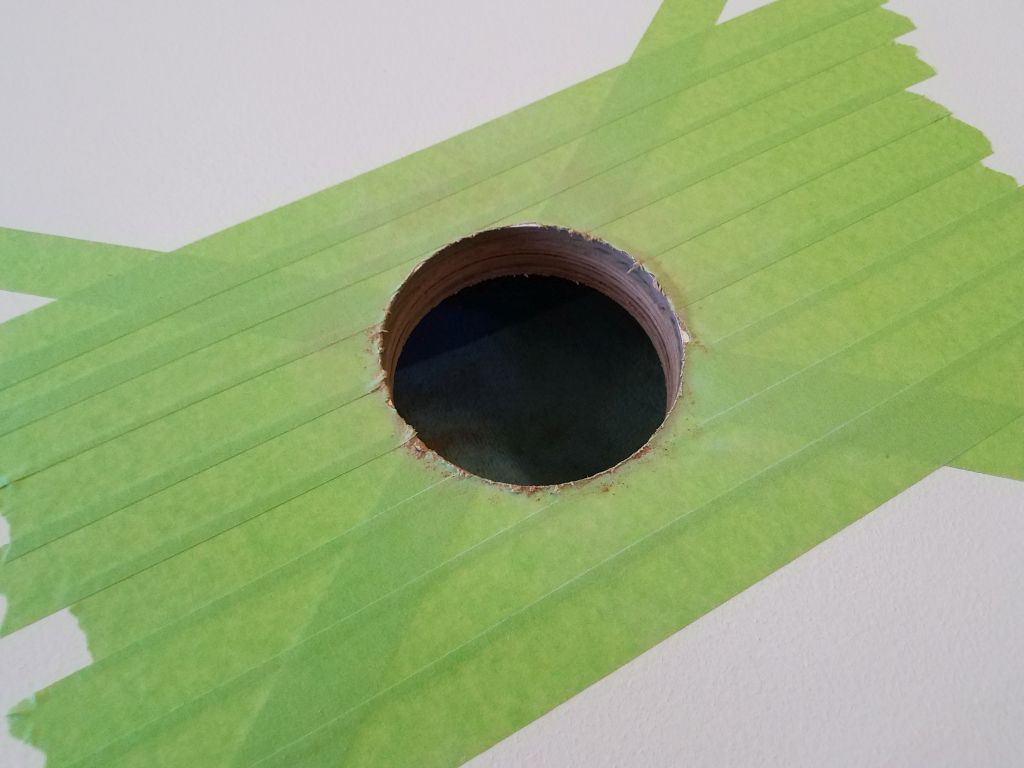
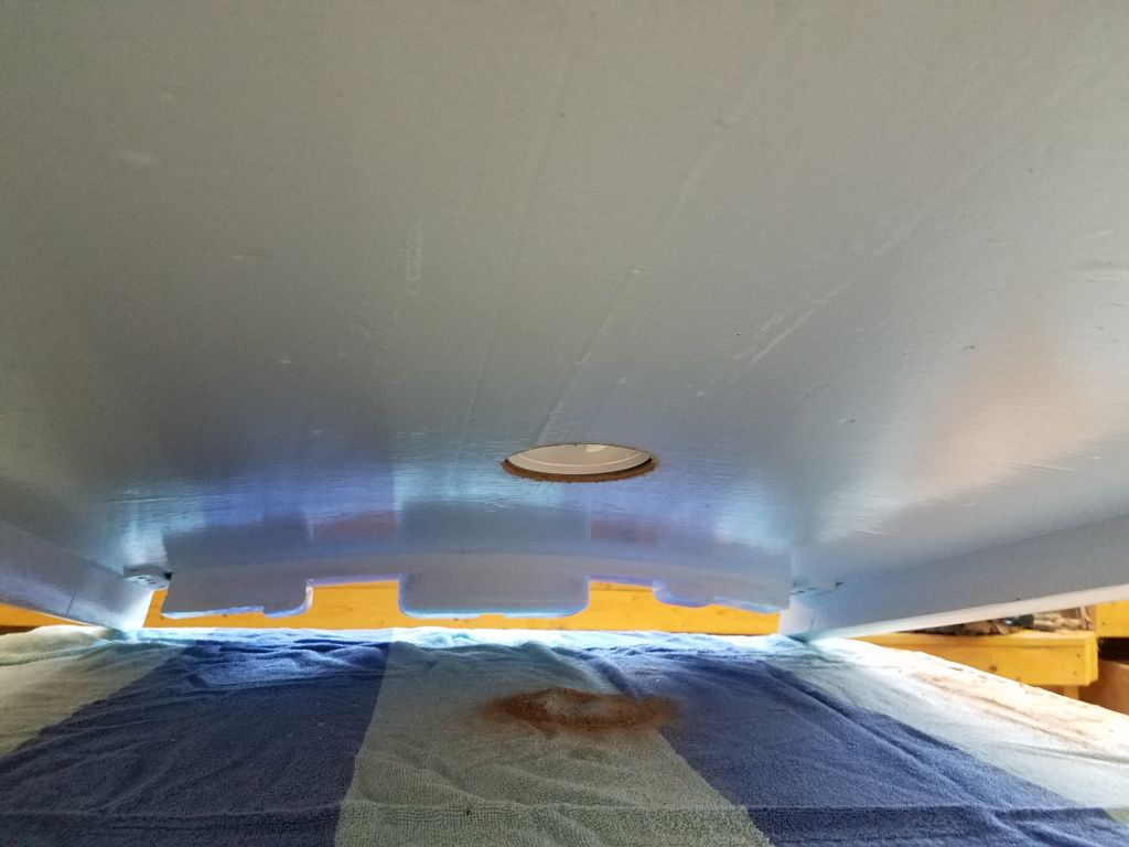
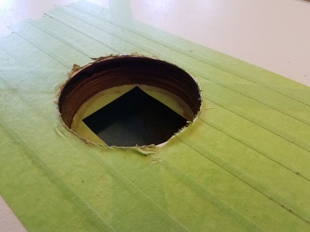
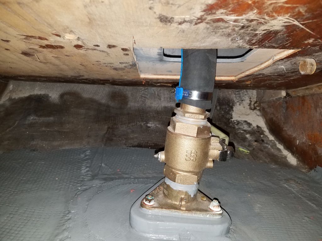
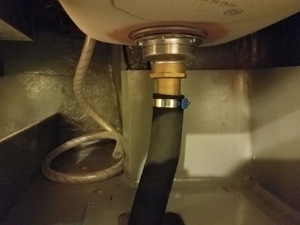
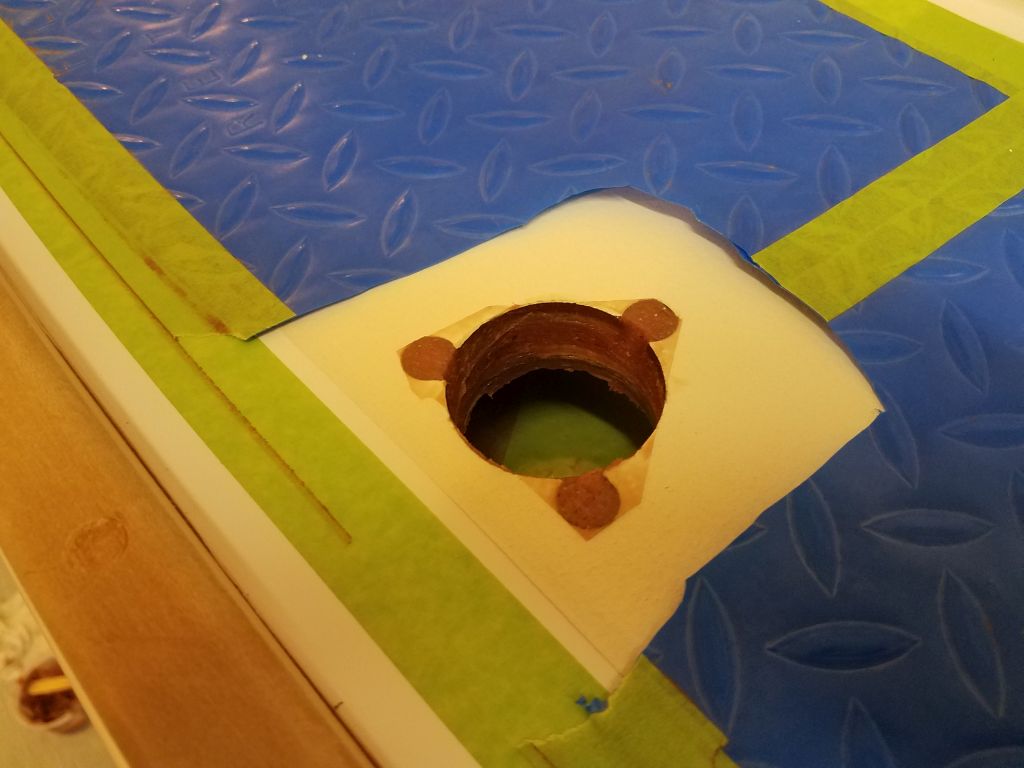
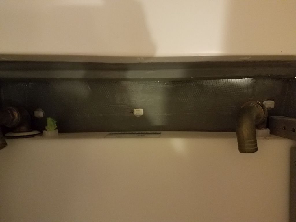
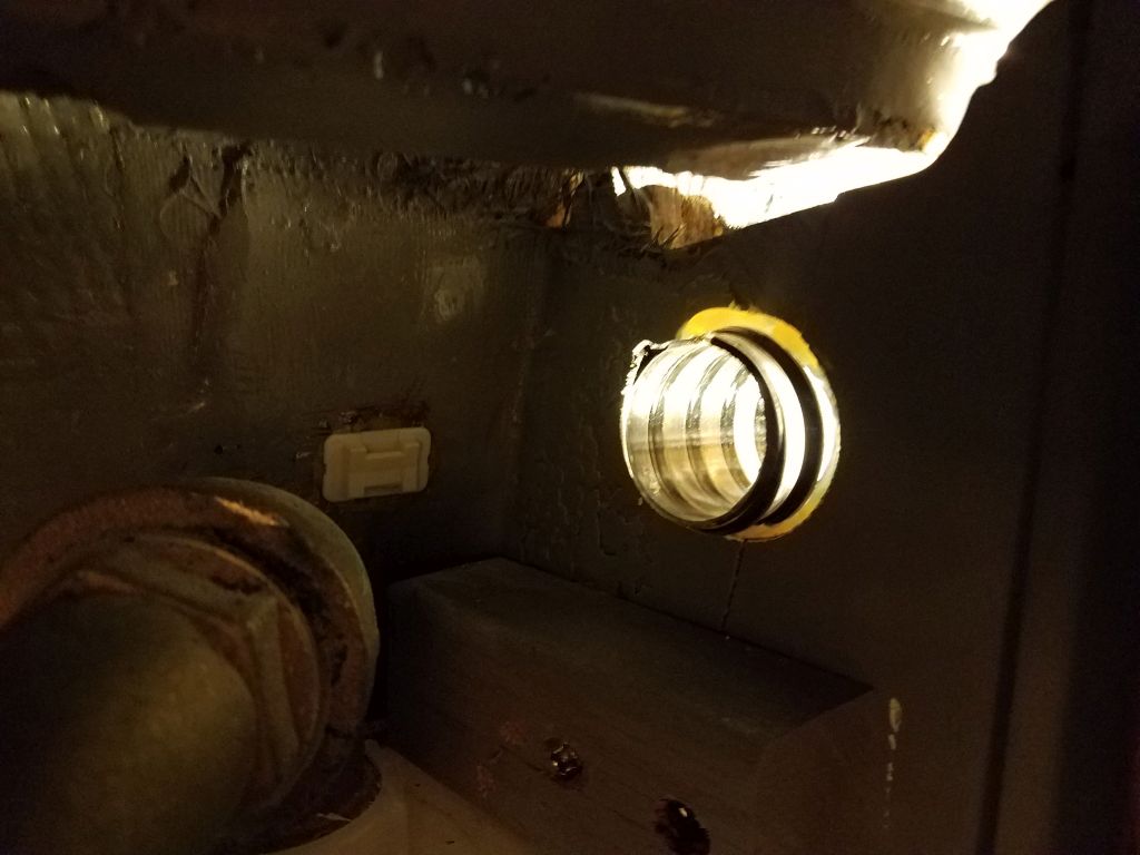
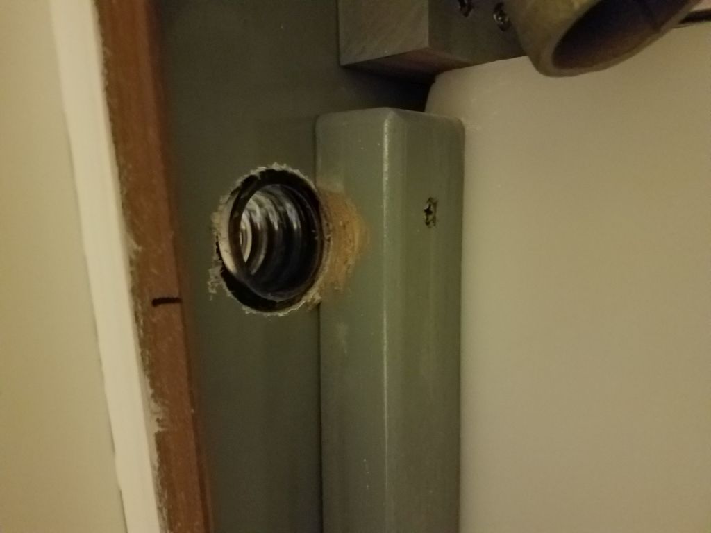
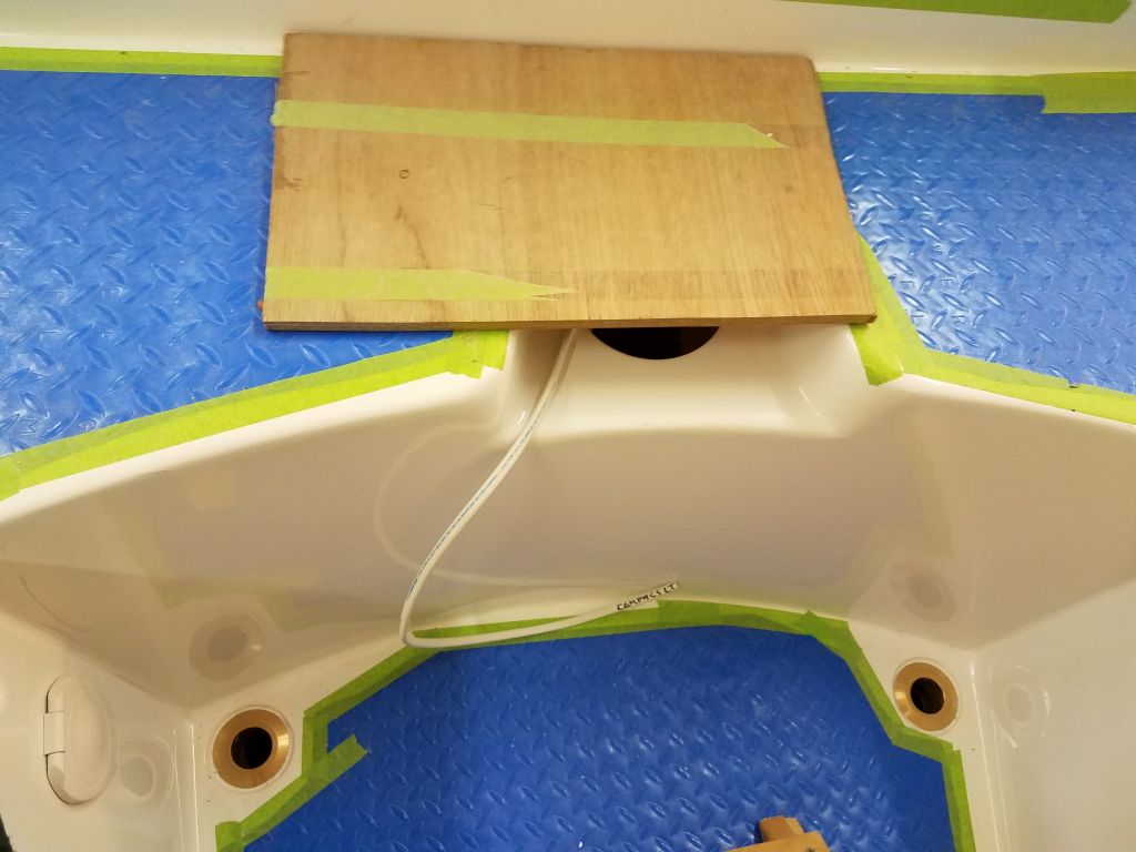
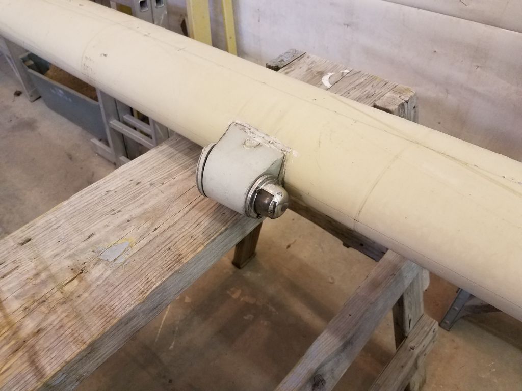
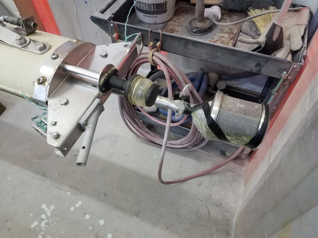
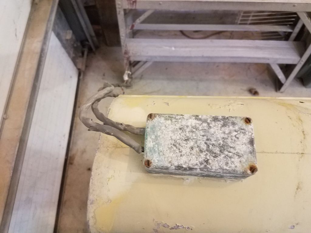
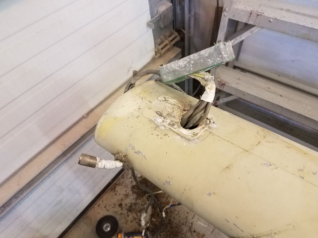
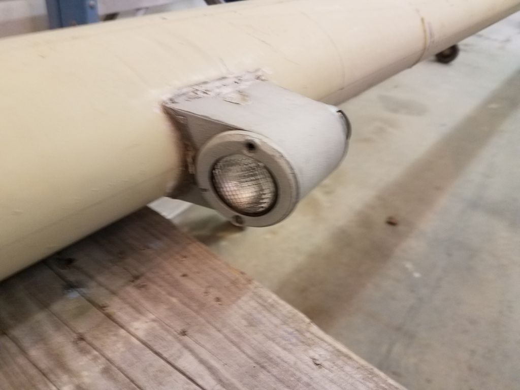
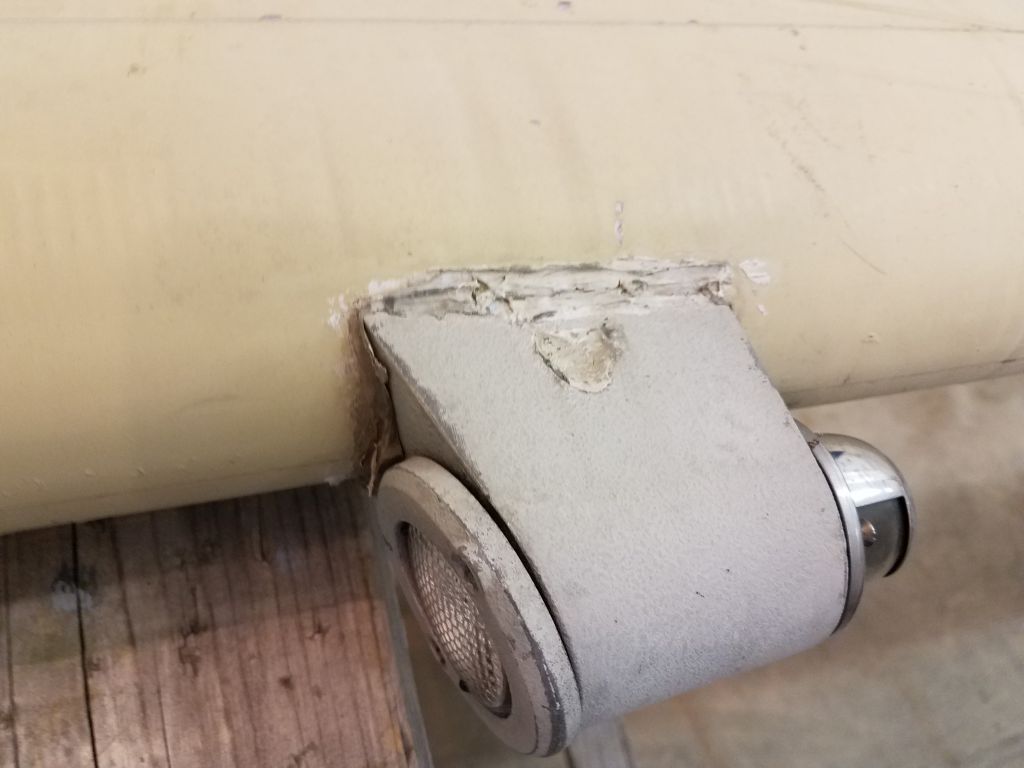
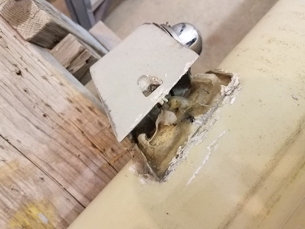
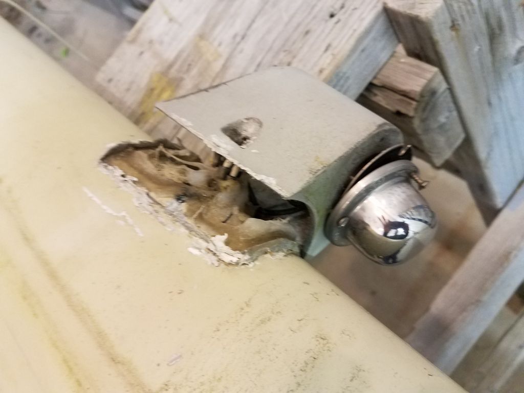
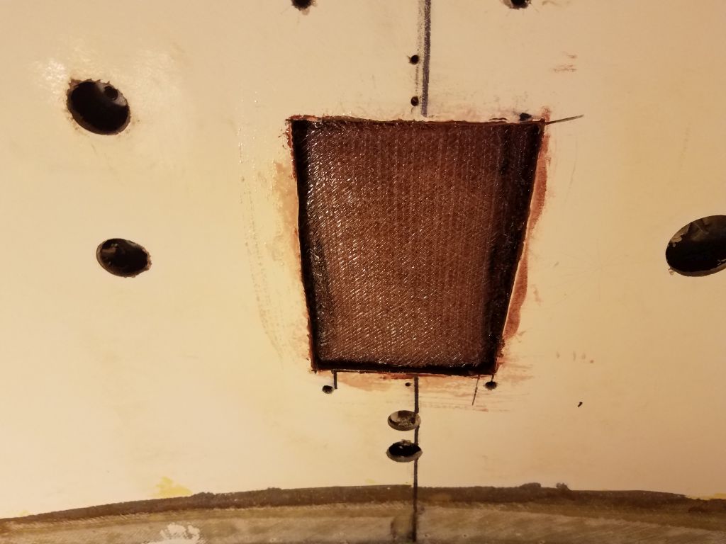
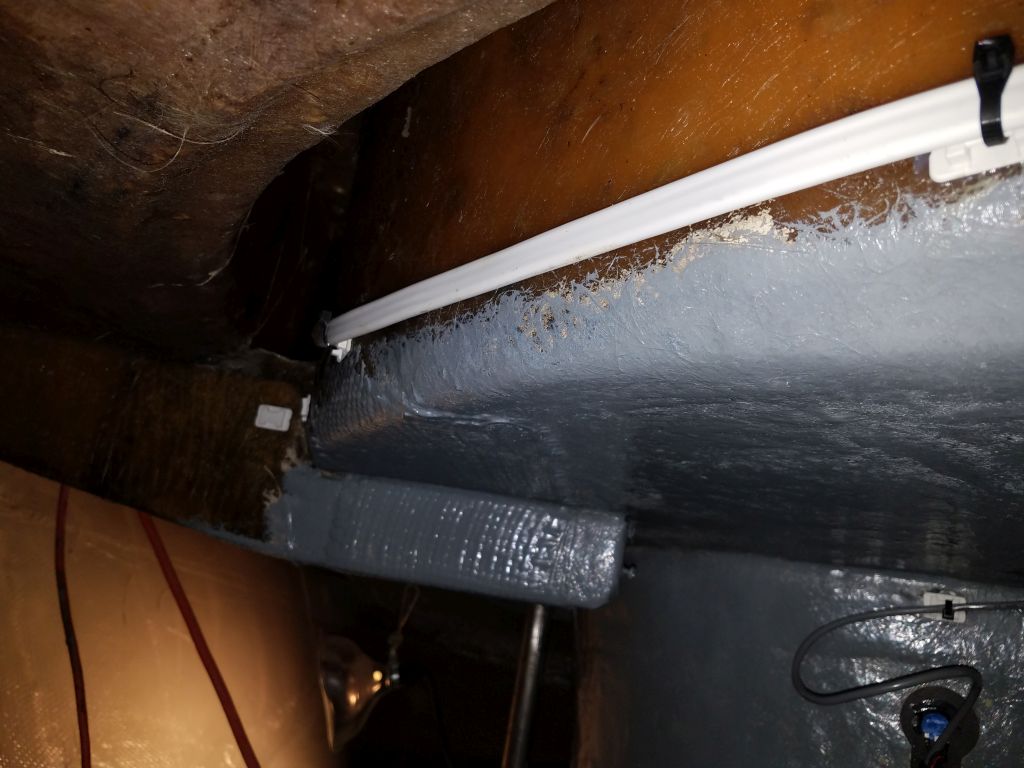
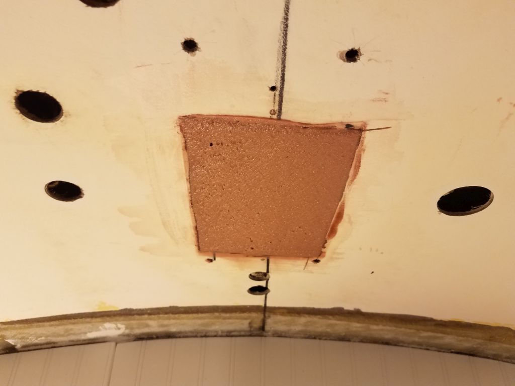
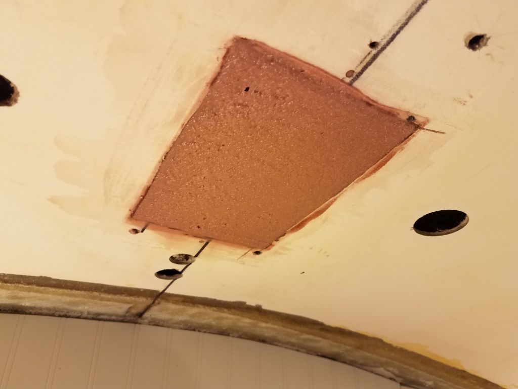
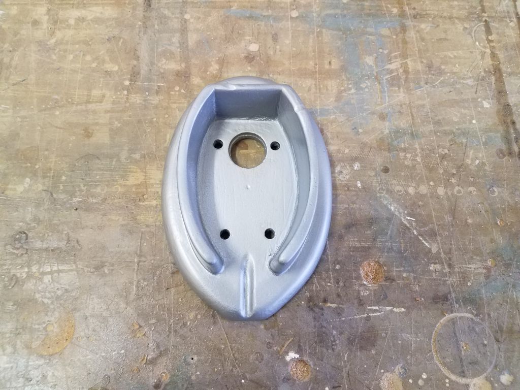
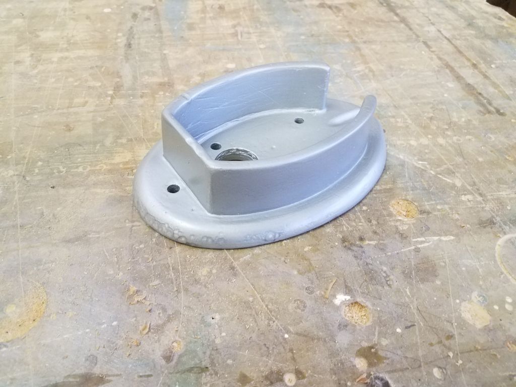
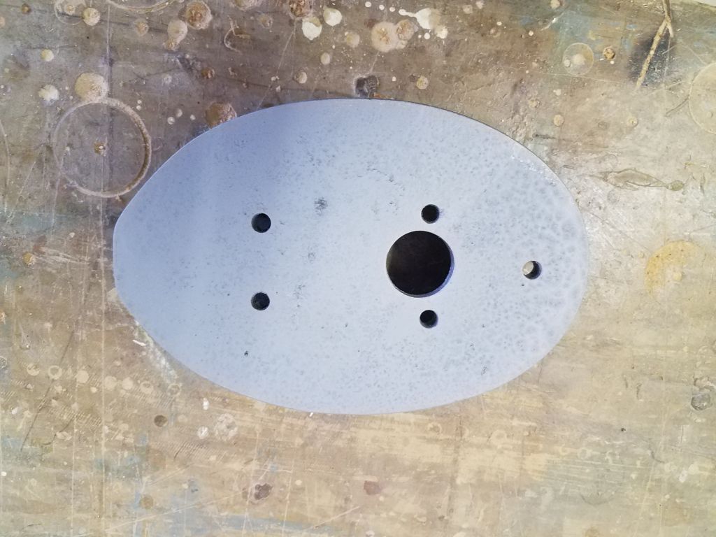
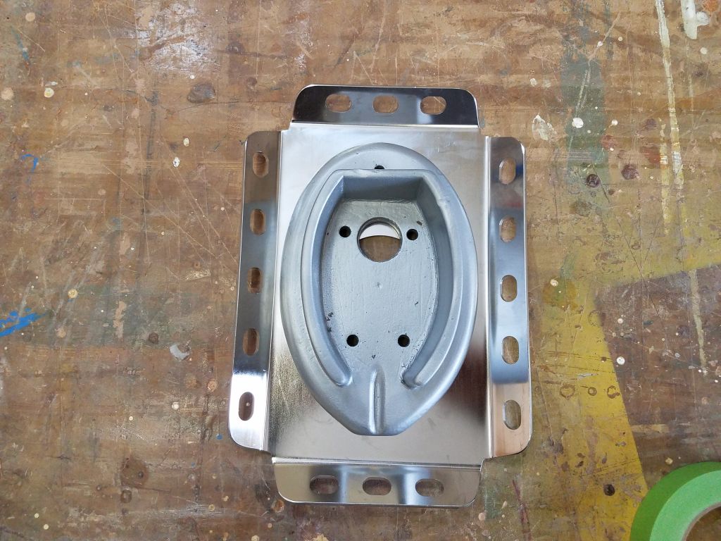
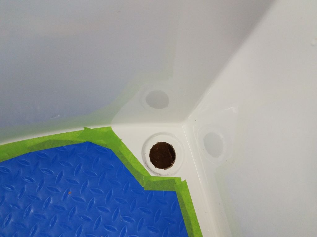
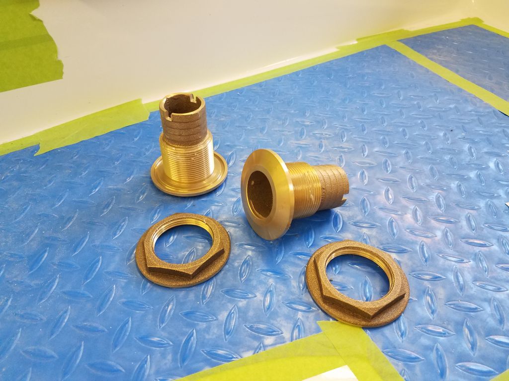
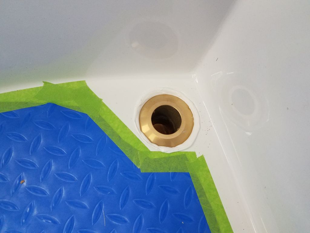
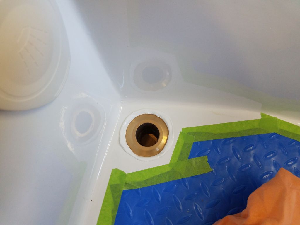
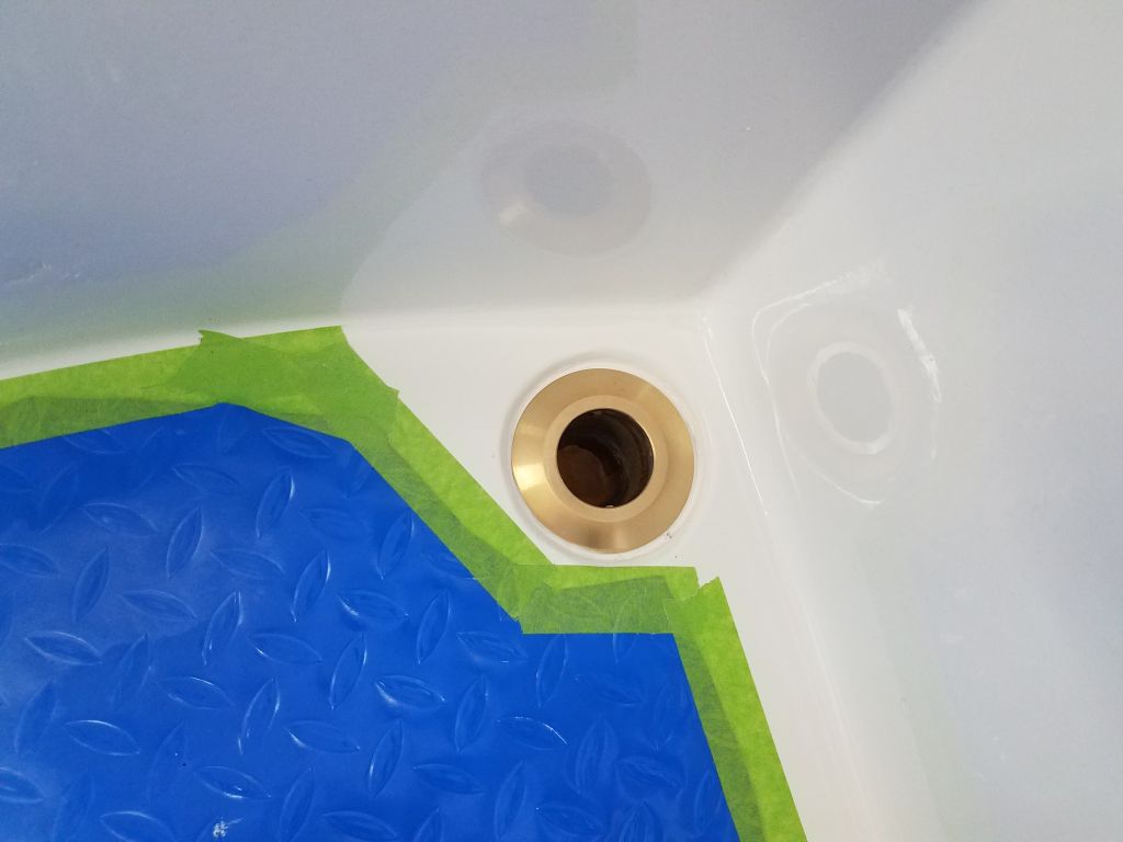
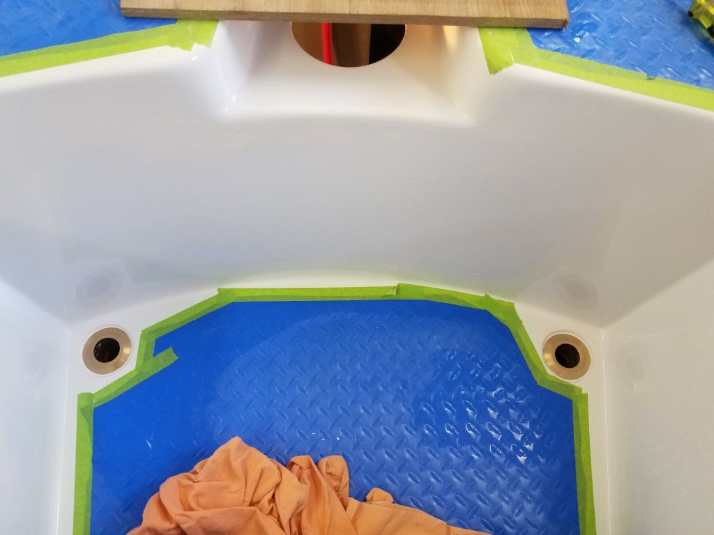
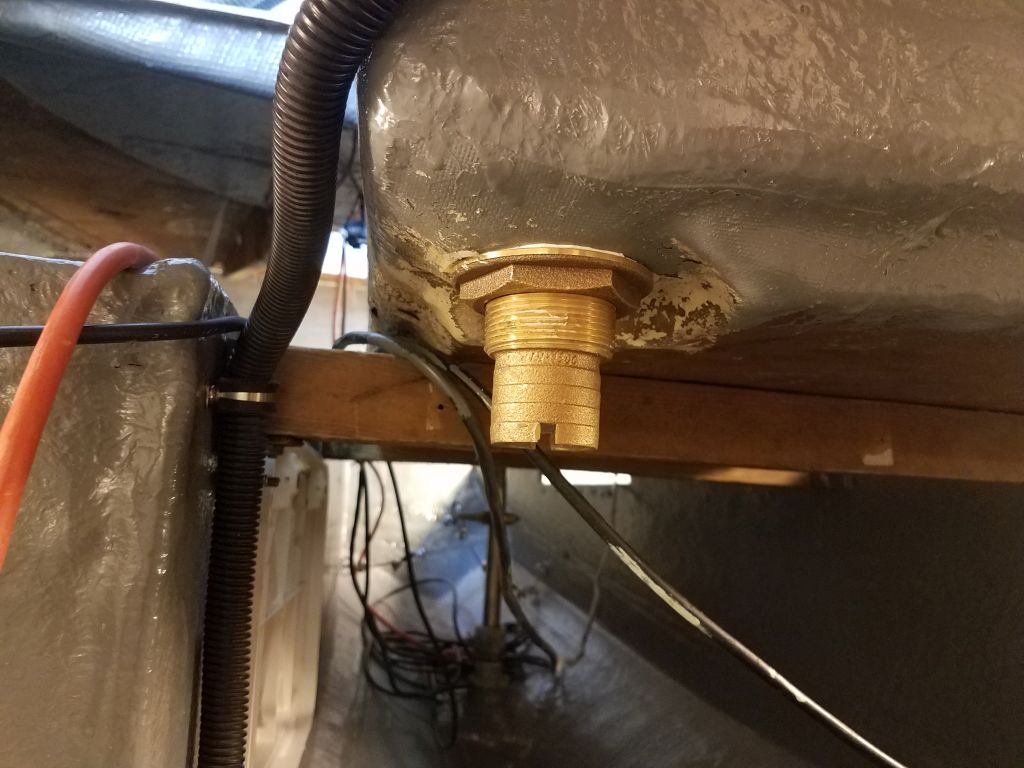
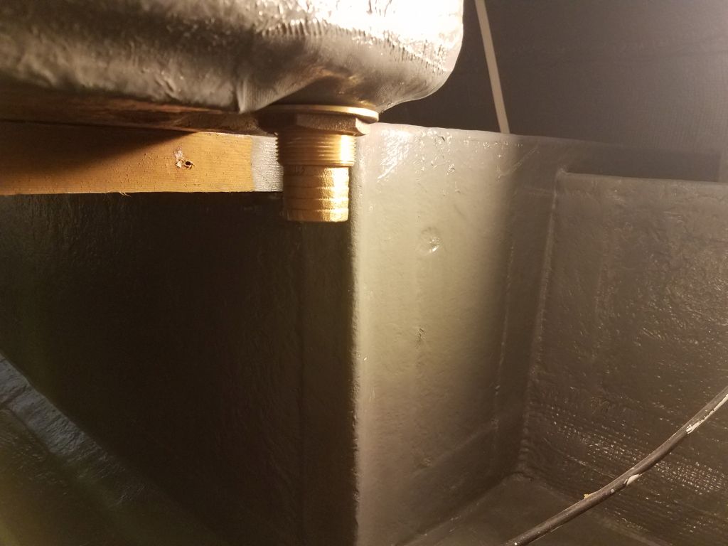
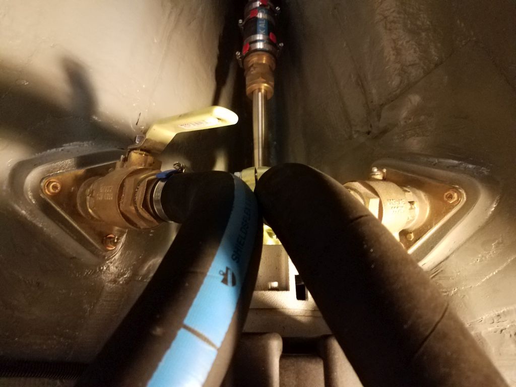
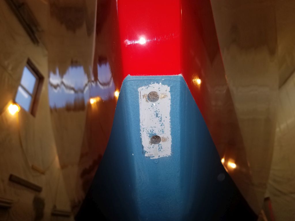
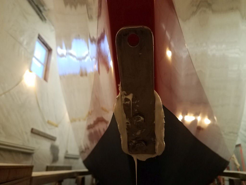
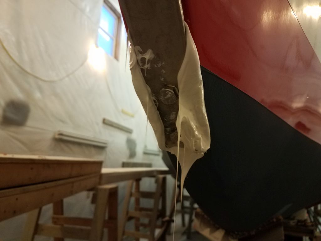
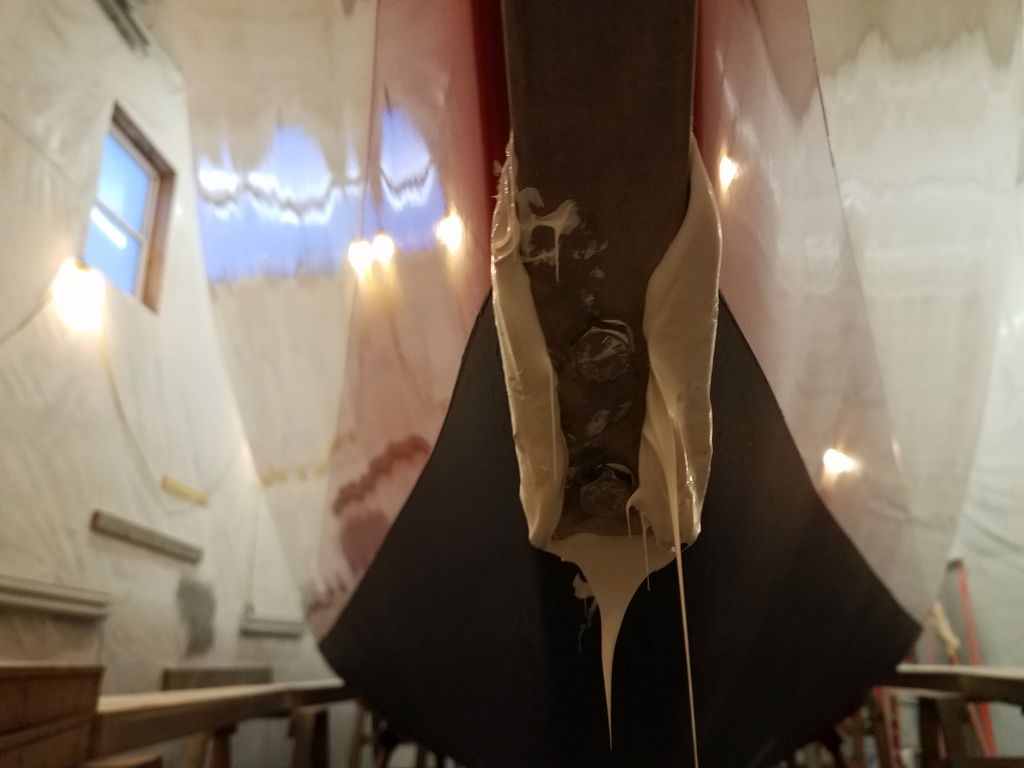
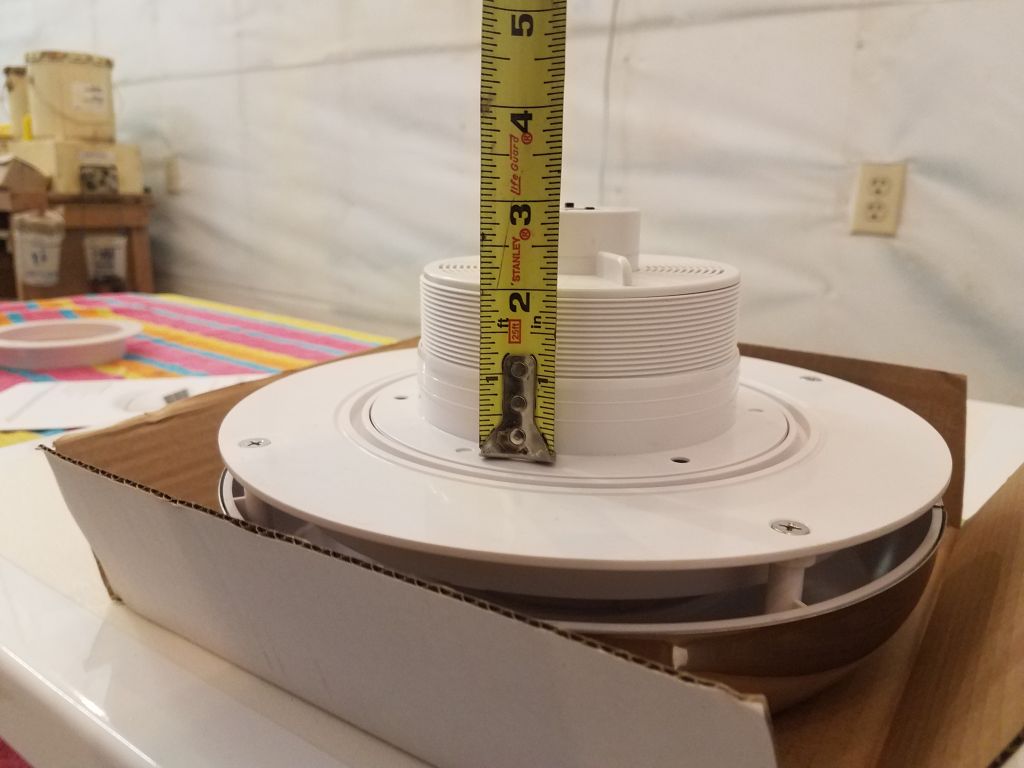
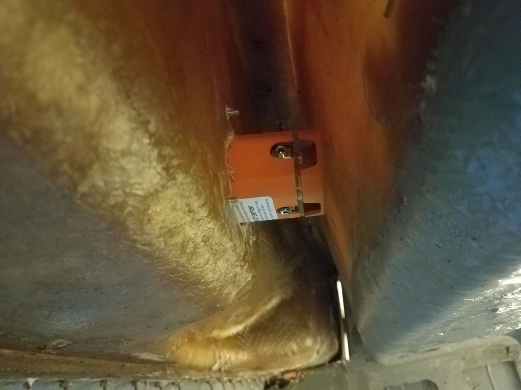
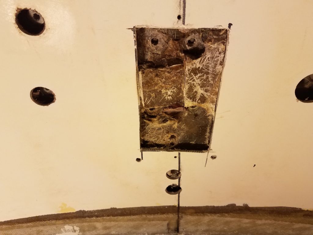
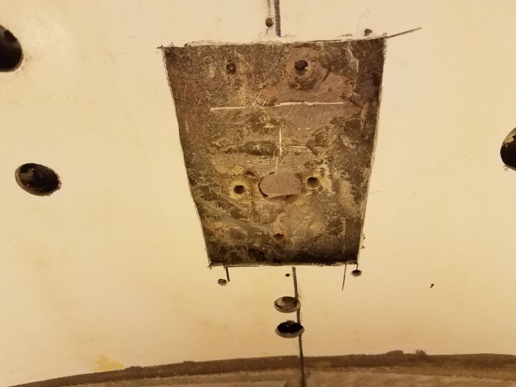
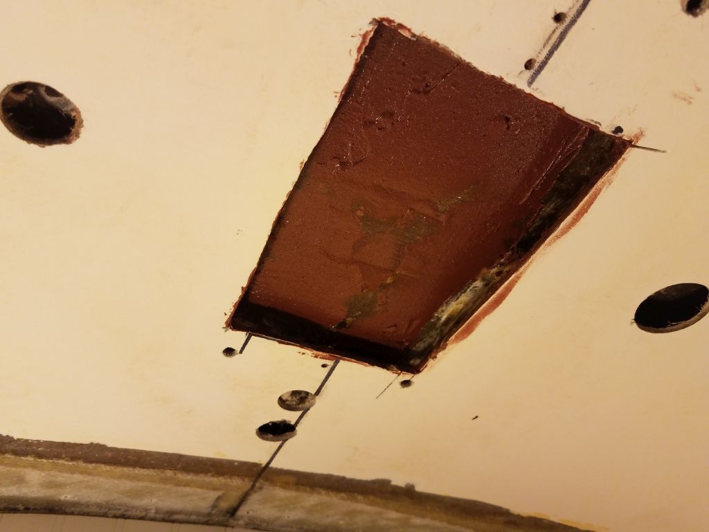
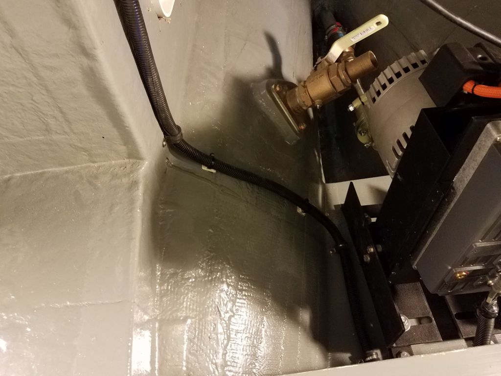
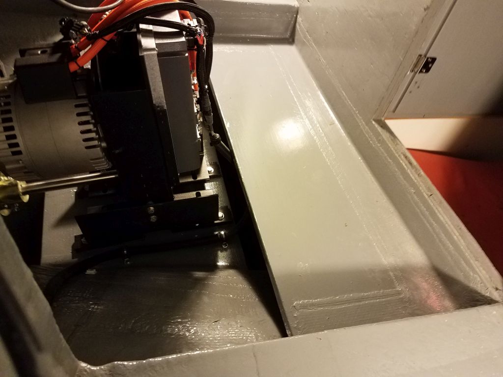
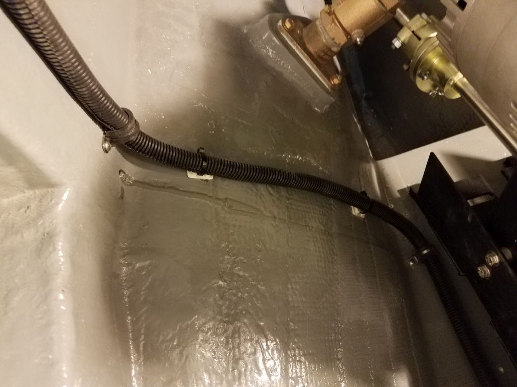
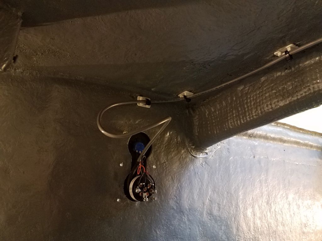
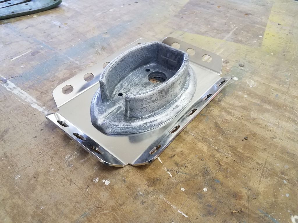
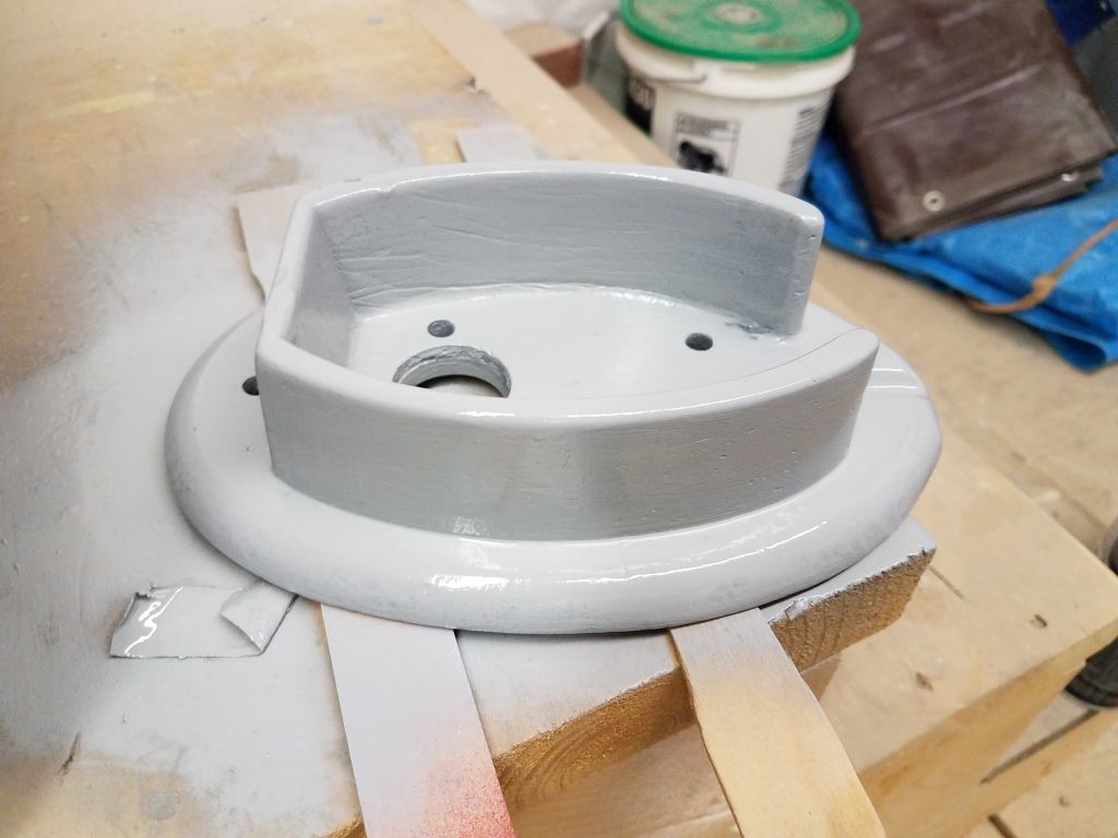
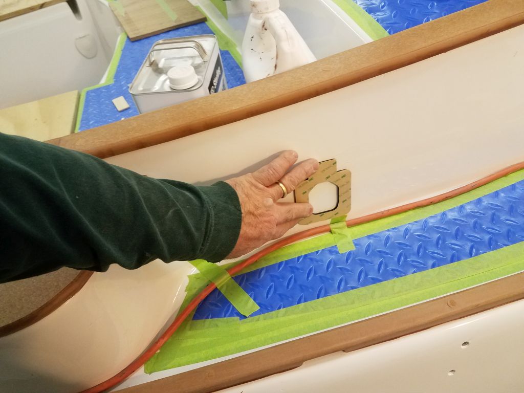
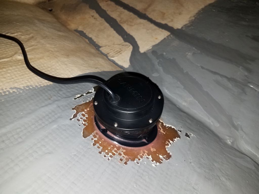
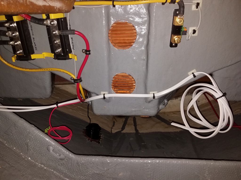
I spent most of the day wiring, starting with the final transducer installation.  The epoxy securing the tank to the hull had had quite a few days to cure, so now I filled the reservoir with mineral oil and installed the transducer and gasket atop.  It would have been nice if there had been a fill line inside to suggest how much oil to install, since the transducer was designed to extend into the tank and would displace a certain amount of the liquid.  I knew if I filled it completely I’d have a mess on my hands, but using one of the spare (differently-angled) tanks that came with the unit, I estimated a reasonable level based on how far the transducer extended in, and when I secured the transducer only a small amount of excess oil was pushed out, minimizing the mess but also confirming that the transducer was completely submerged within.  I was at the ready with rags.  I planned to come back later and touch up the gray paint around the transducer.

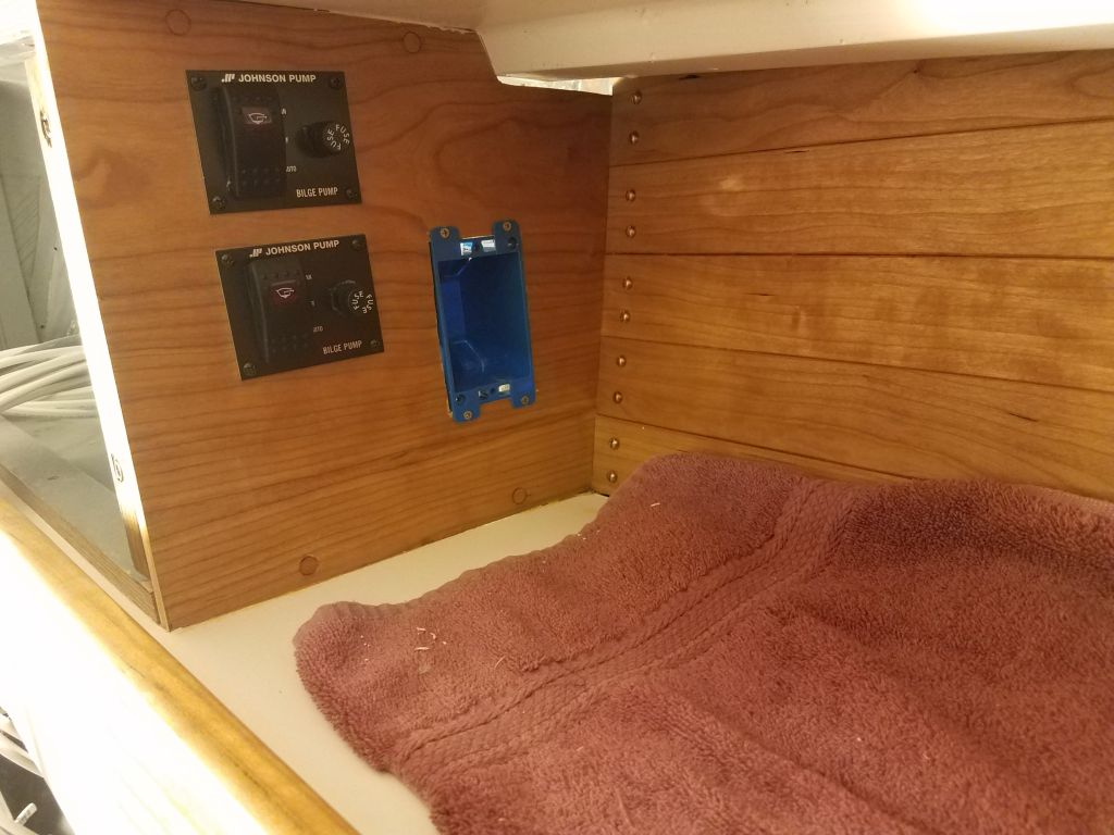
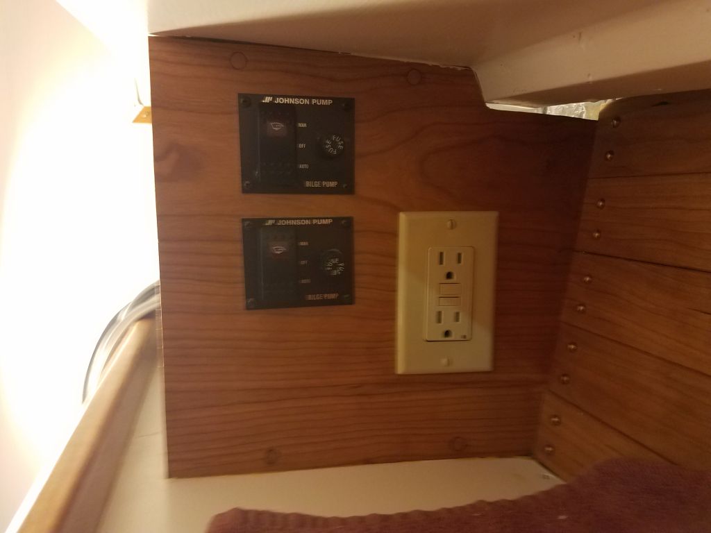
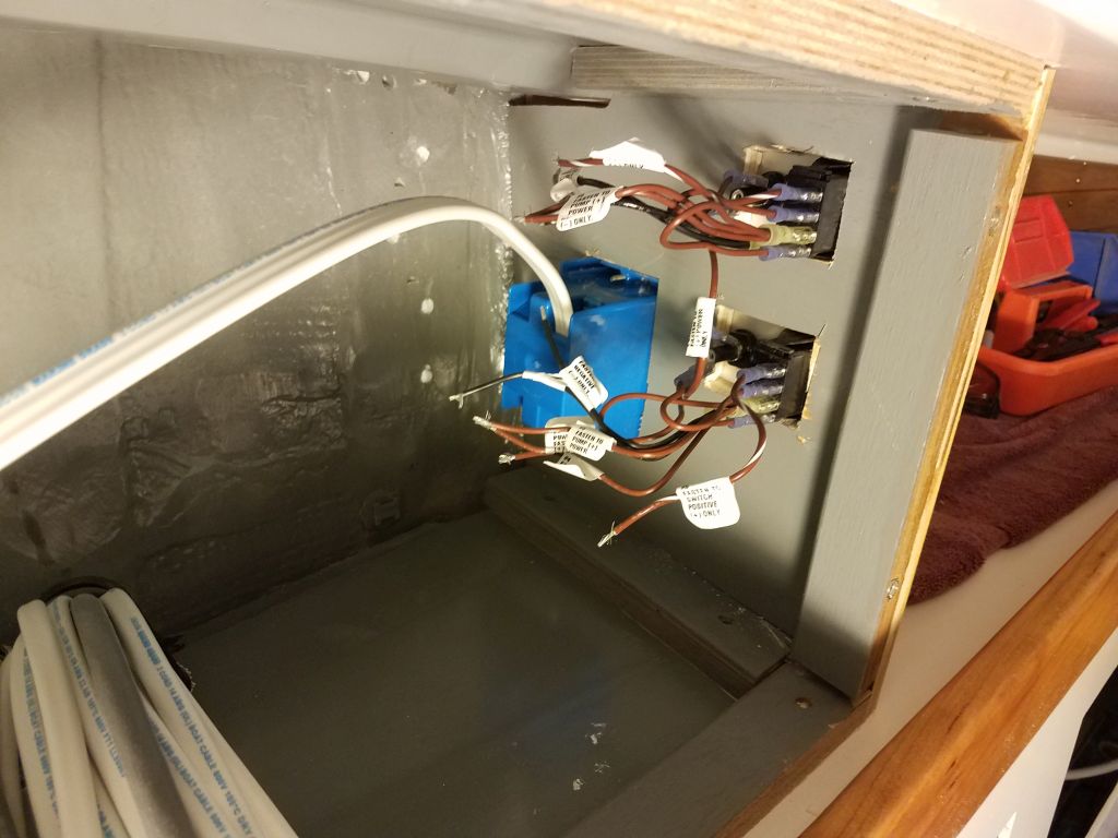
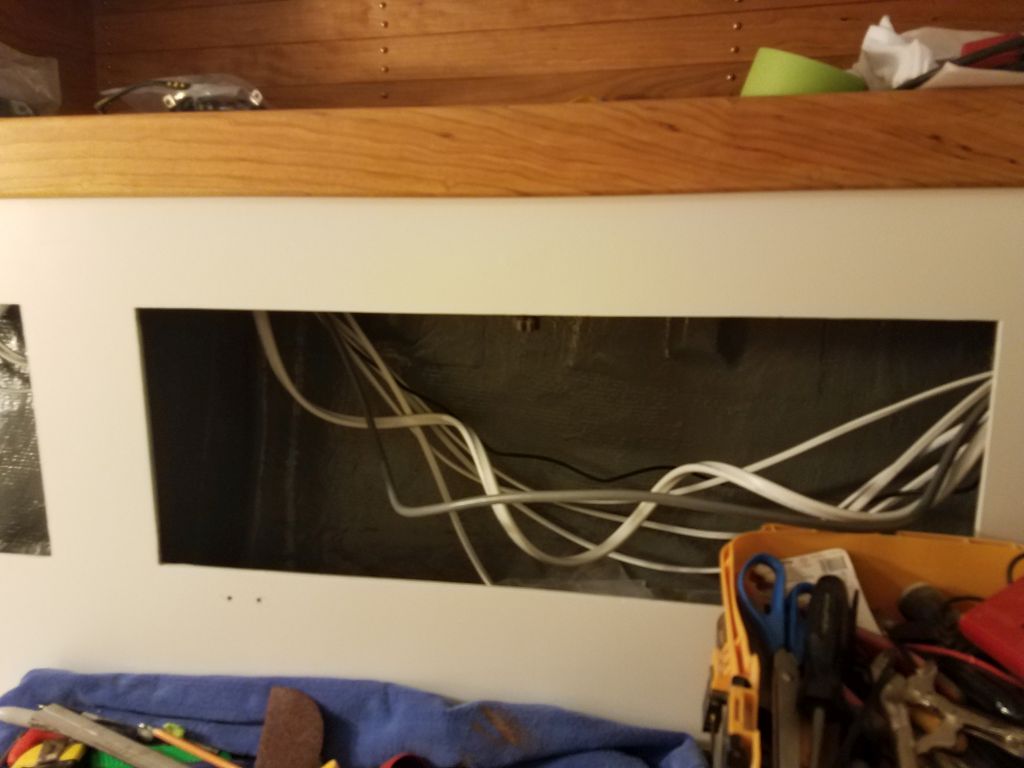
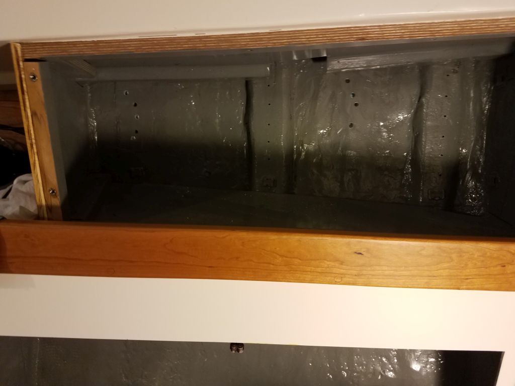
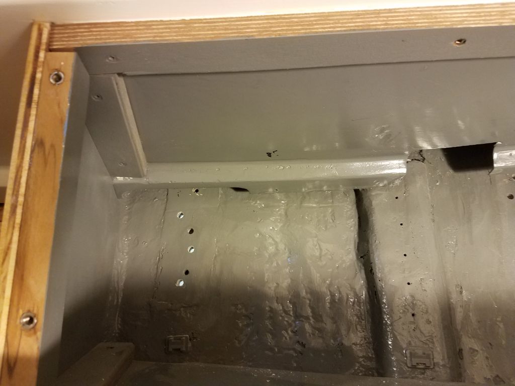
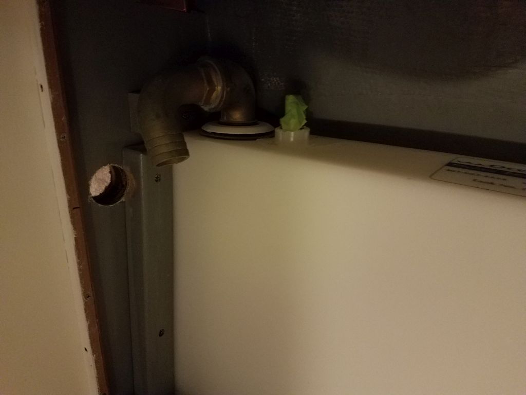
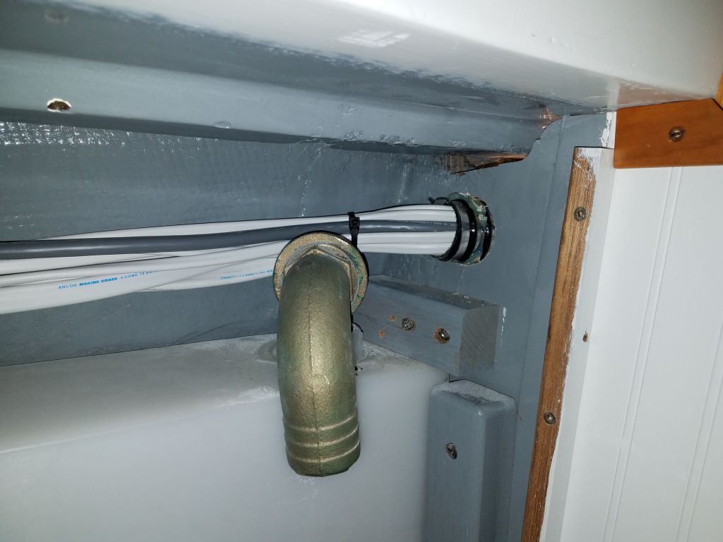
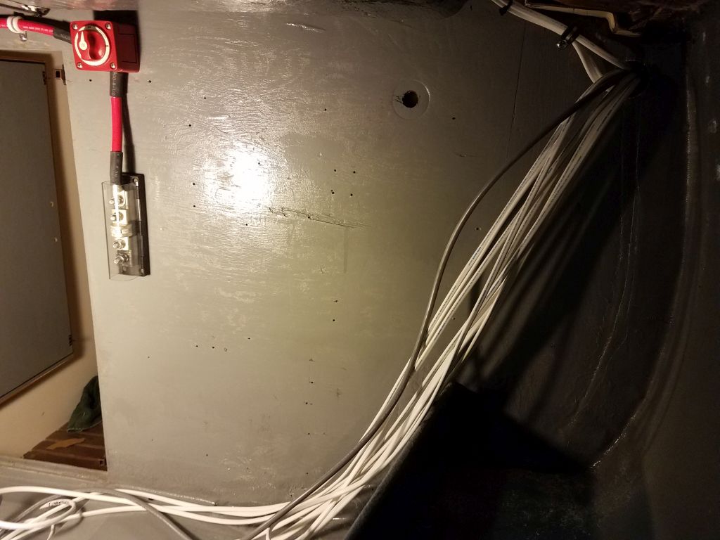
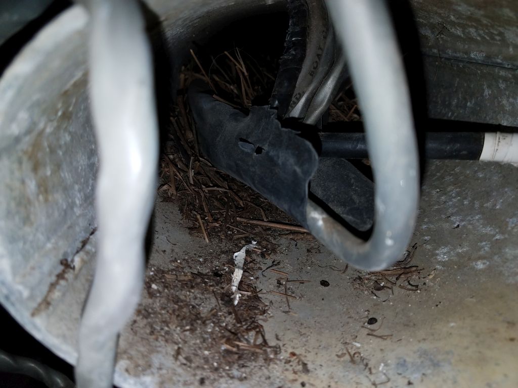
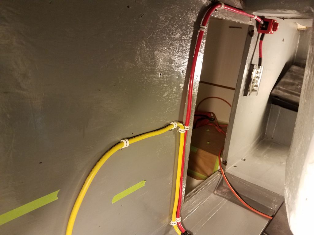
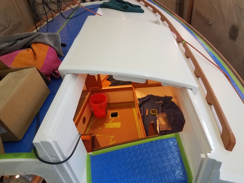
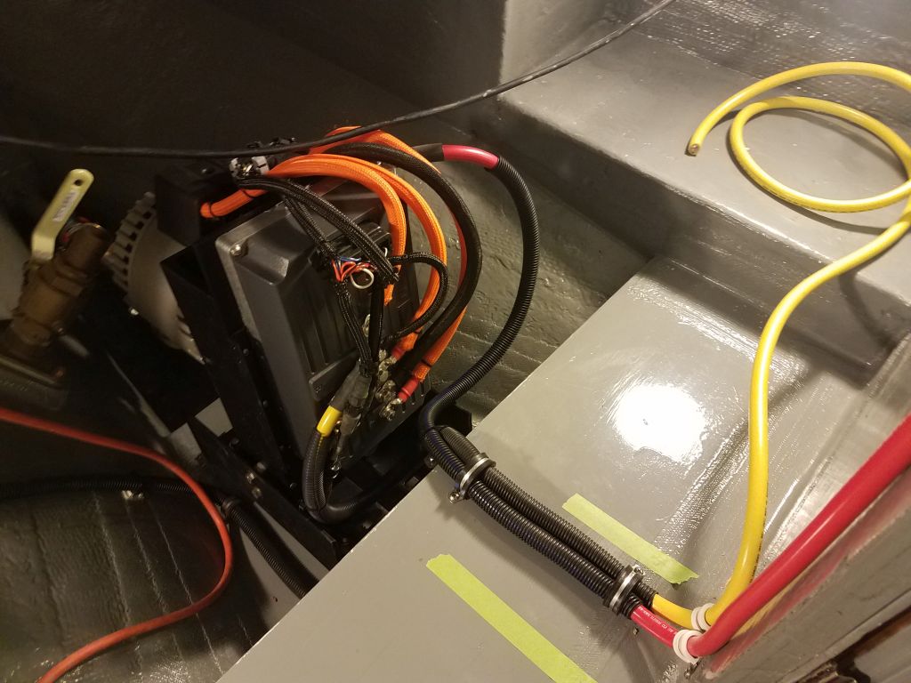
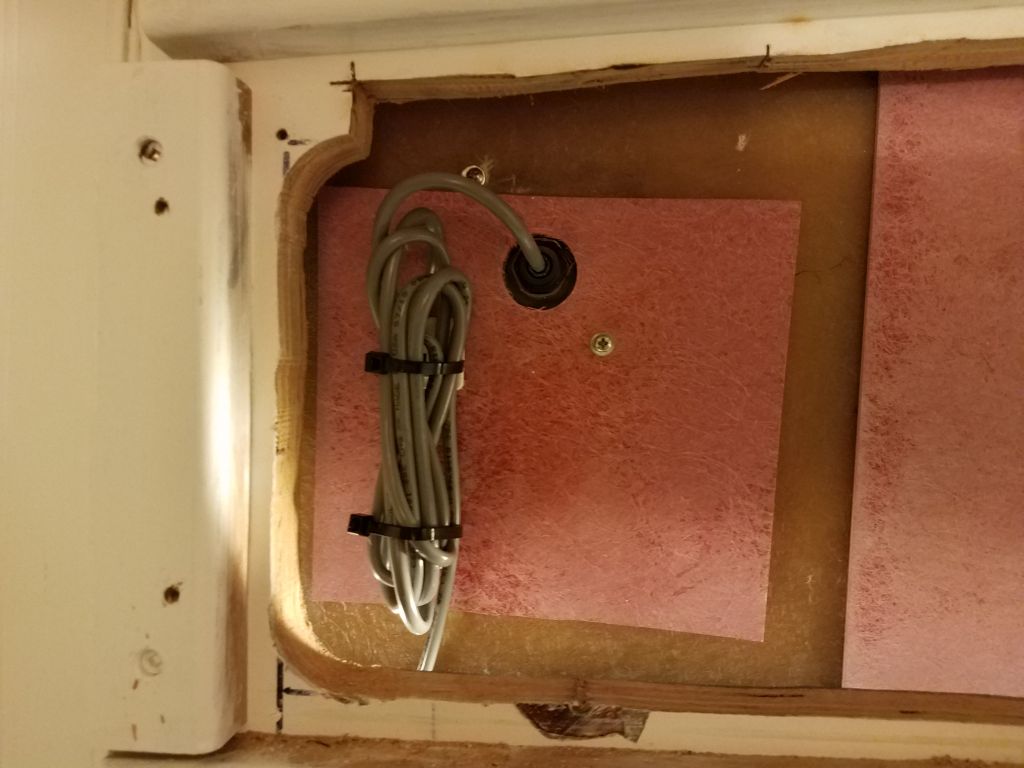
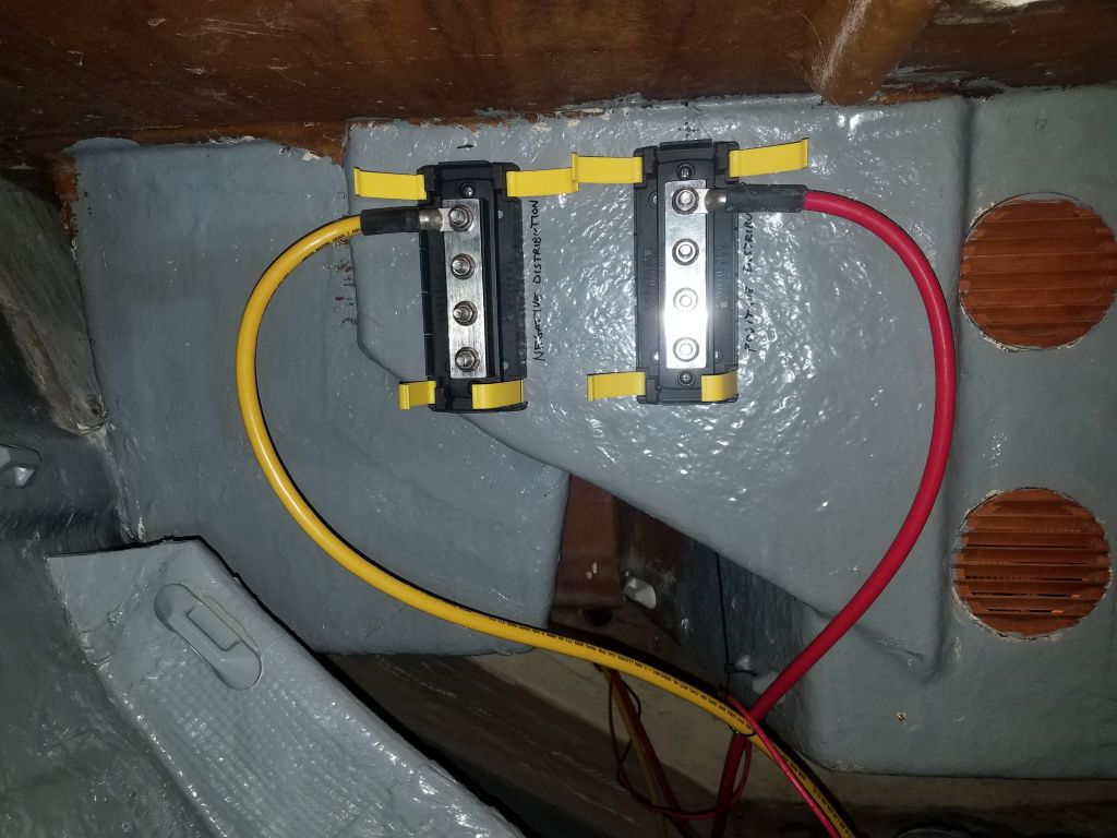
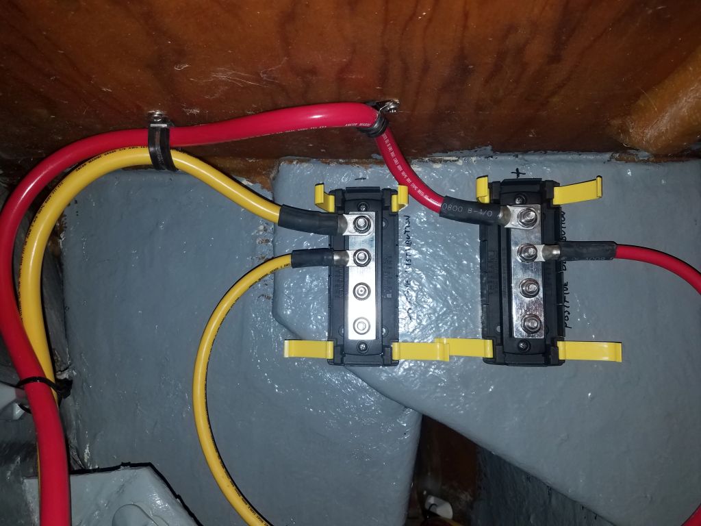
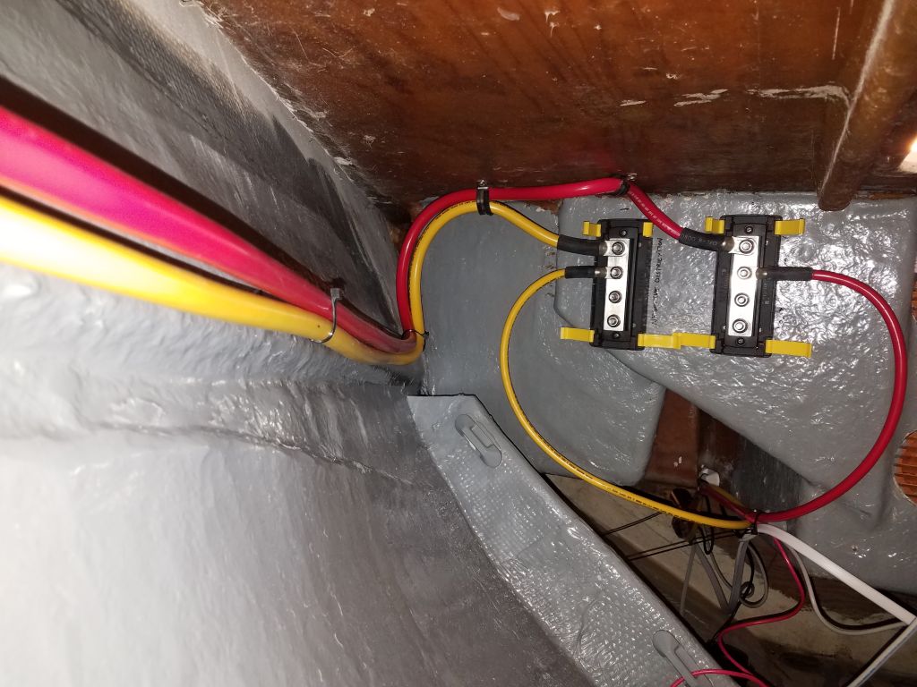
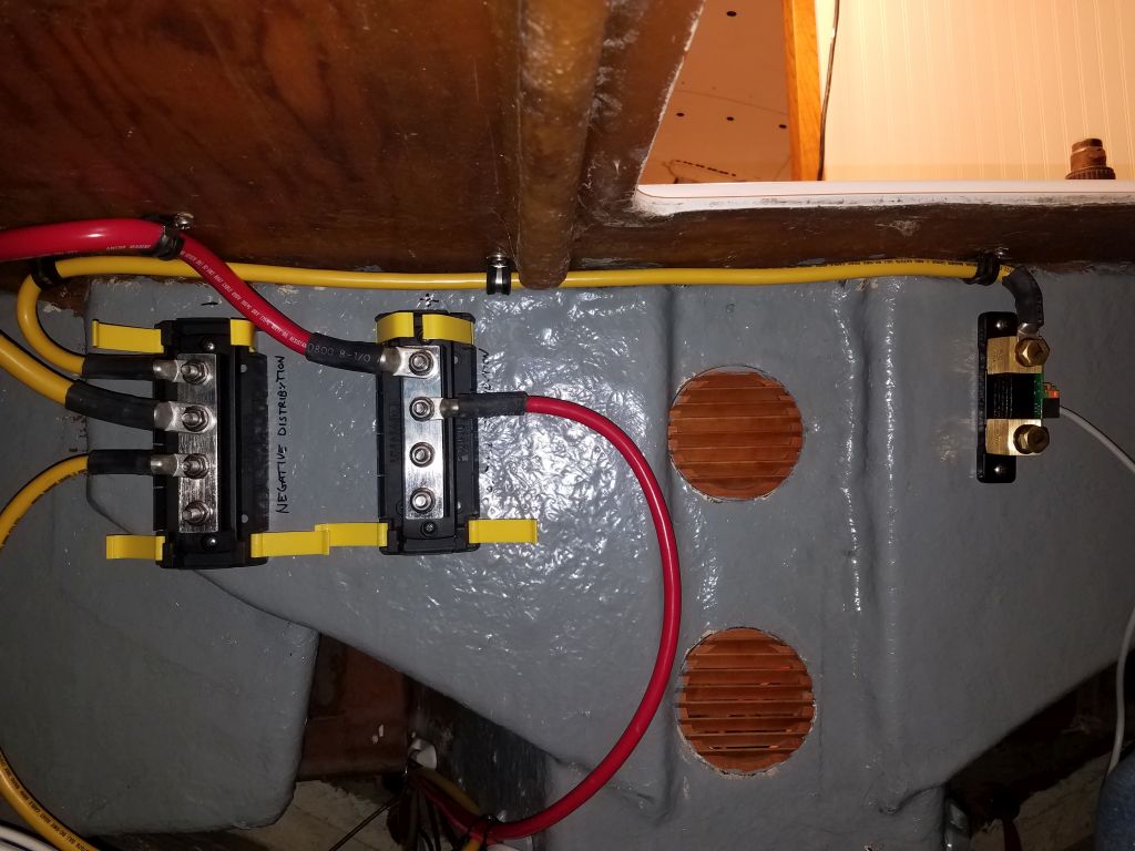
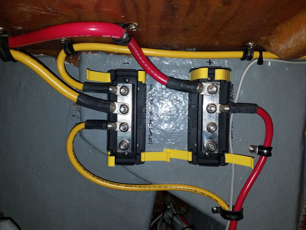
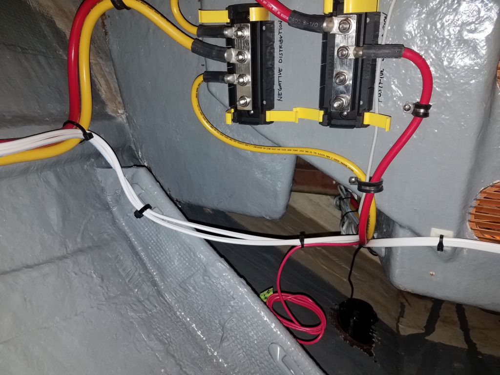
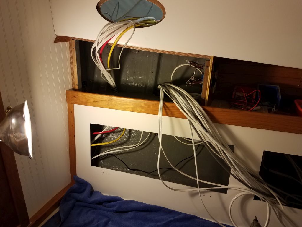
Now that the wiring runs leading aft along the starboard side were all roughly in place, I continued the wiring project with various wires and cables leading from the electrical panel area forward into the storage and utility space beneath the v-berth.  Here, there would eventually be a completely separate house bank of batteries to service  the lighting and all other loads unrelated to the propulsion system.  I began with a pair of #2 battery cables that would provide the main power supply from the house battery to the panel, sized to be substantially larger than required for the anticipated electrical loads.  In the forward locker, I chose a location for the two main distribution busses and installed them, then made up the cable ends before pulling most of the slack back into the electrical panel area for later termination.  The distribution busses were an ongoing work, and one might notice the cables’ positions changing through the remainder of the day’s work.

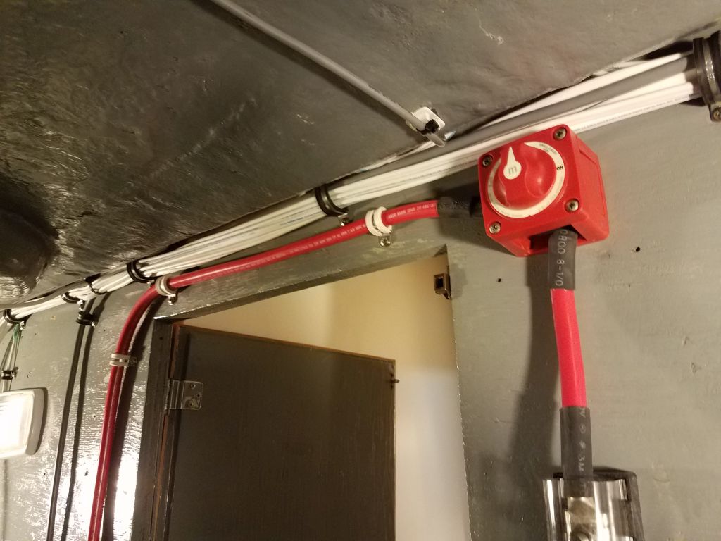
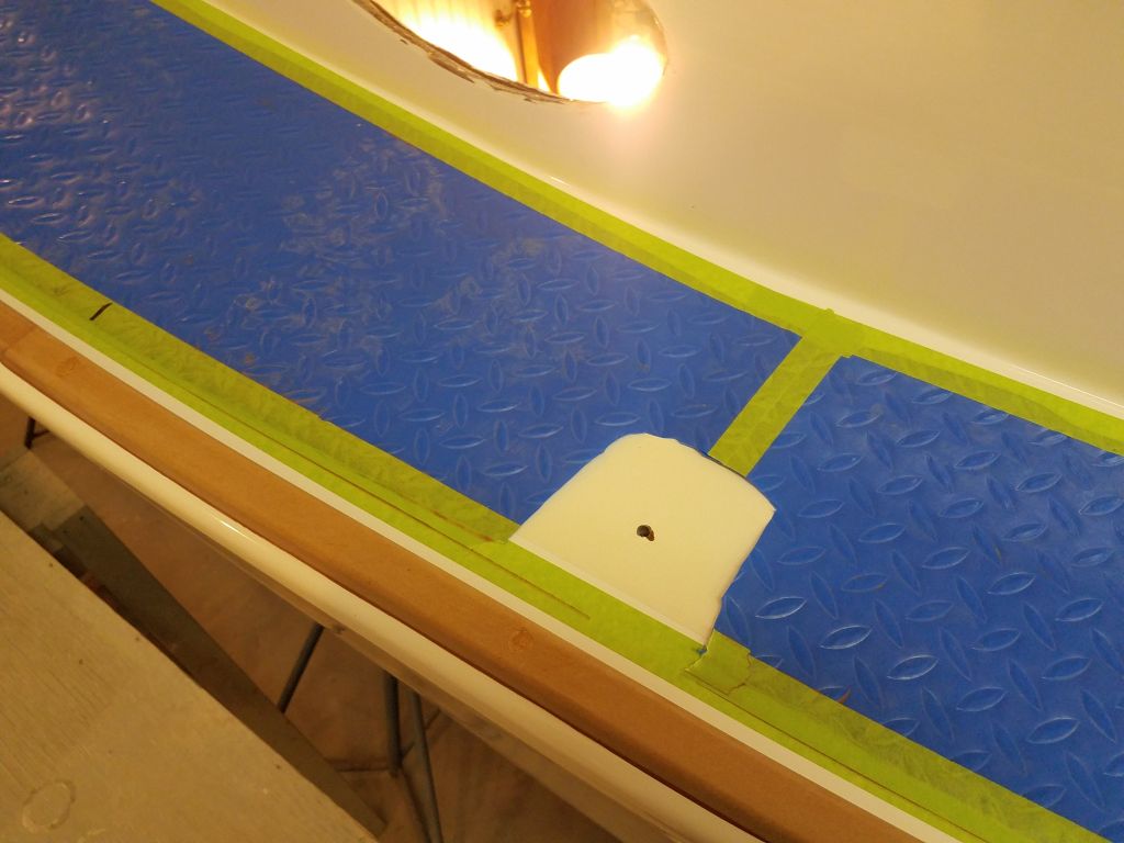
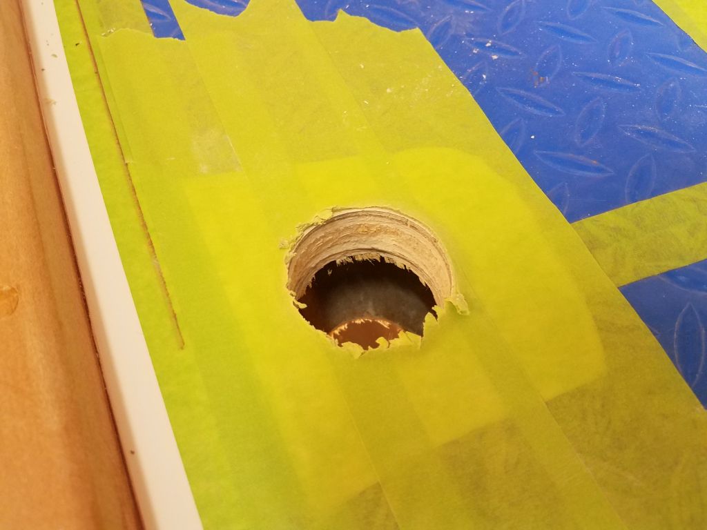
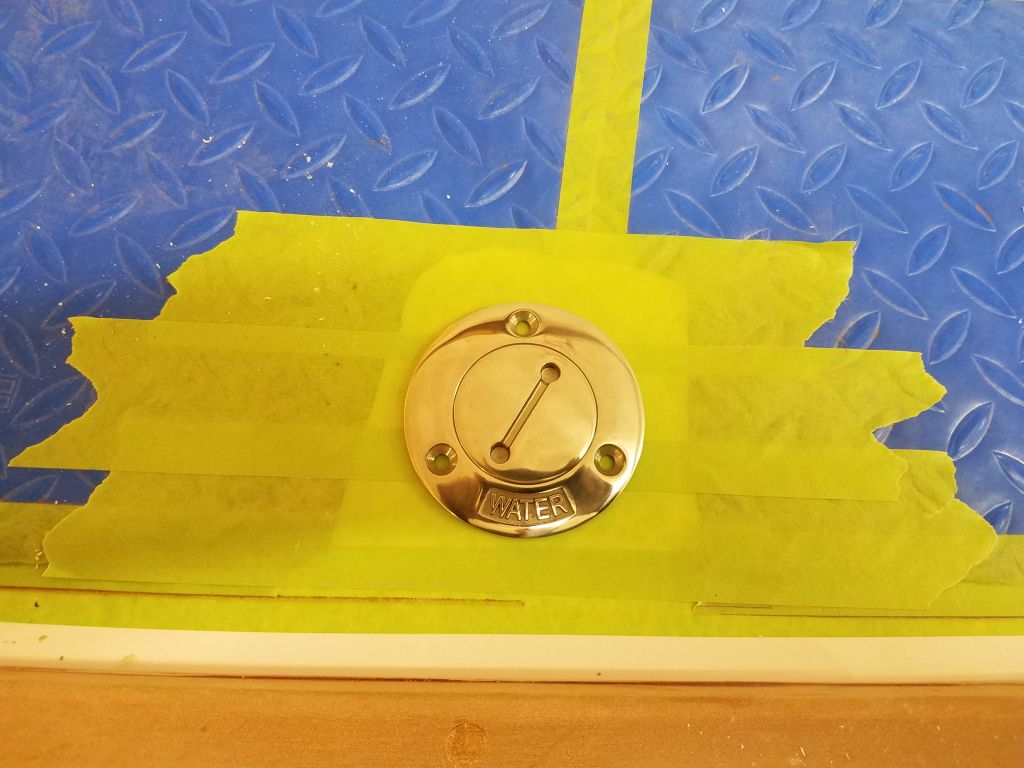
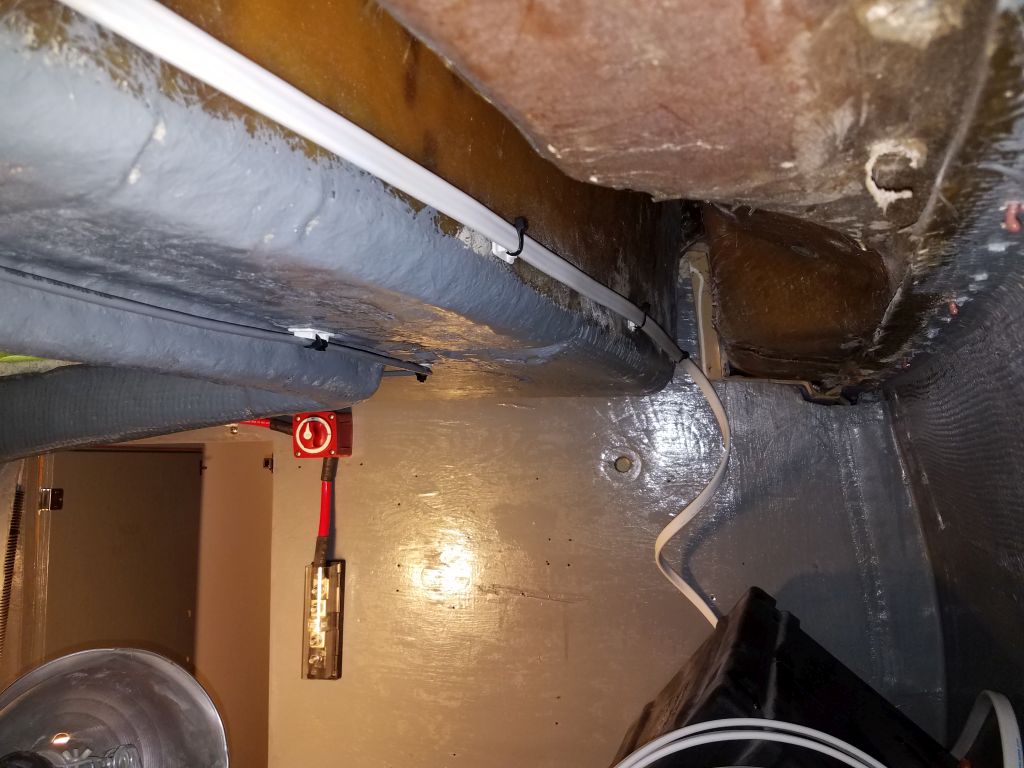
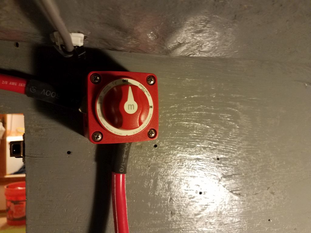
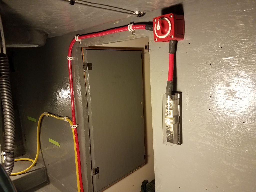
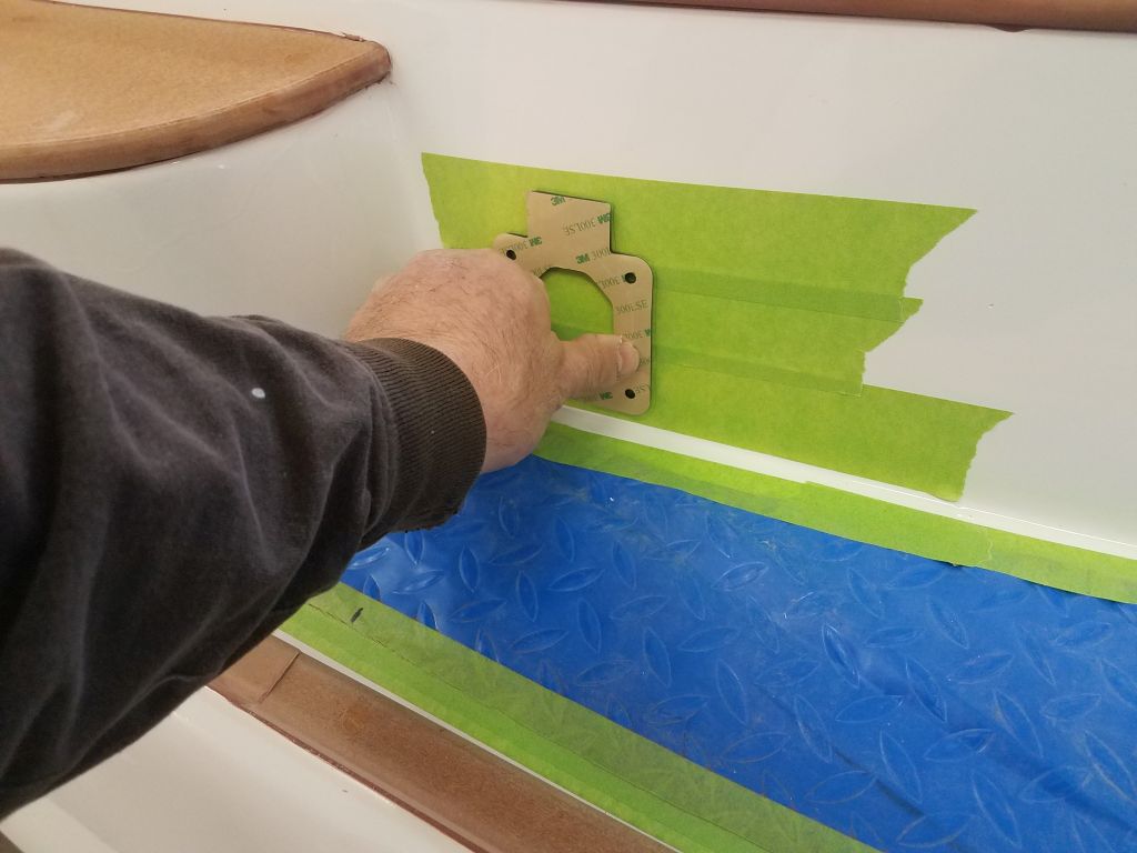
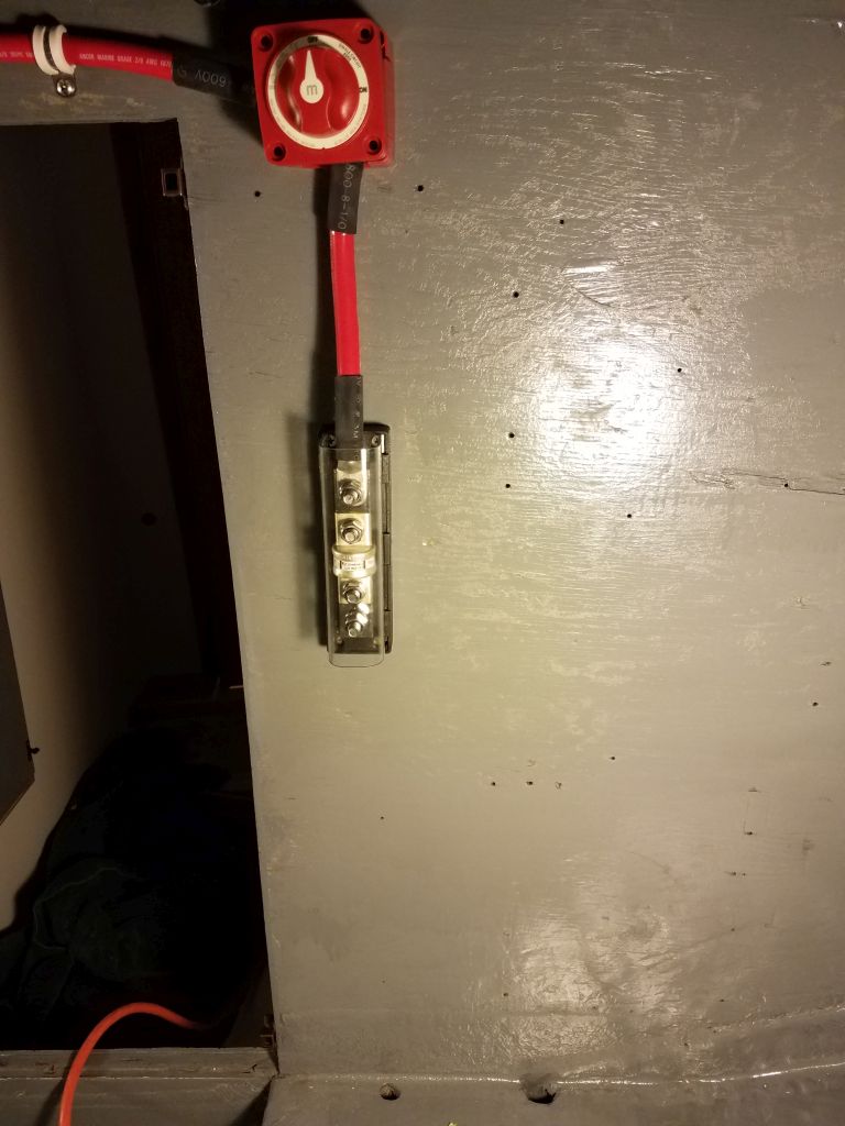
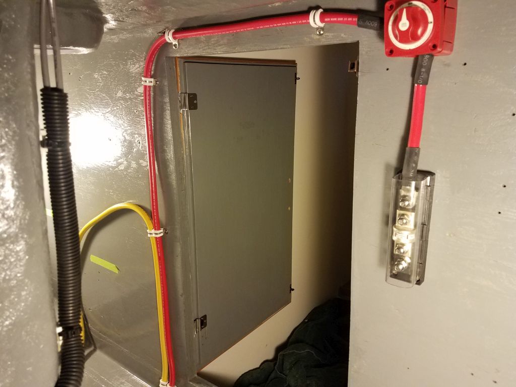
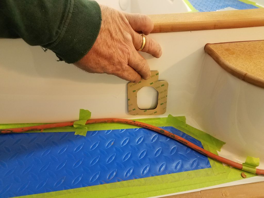
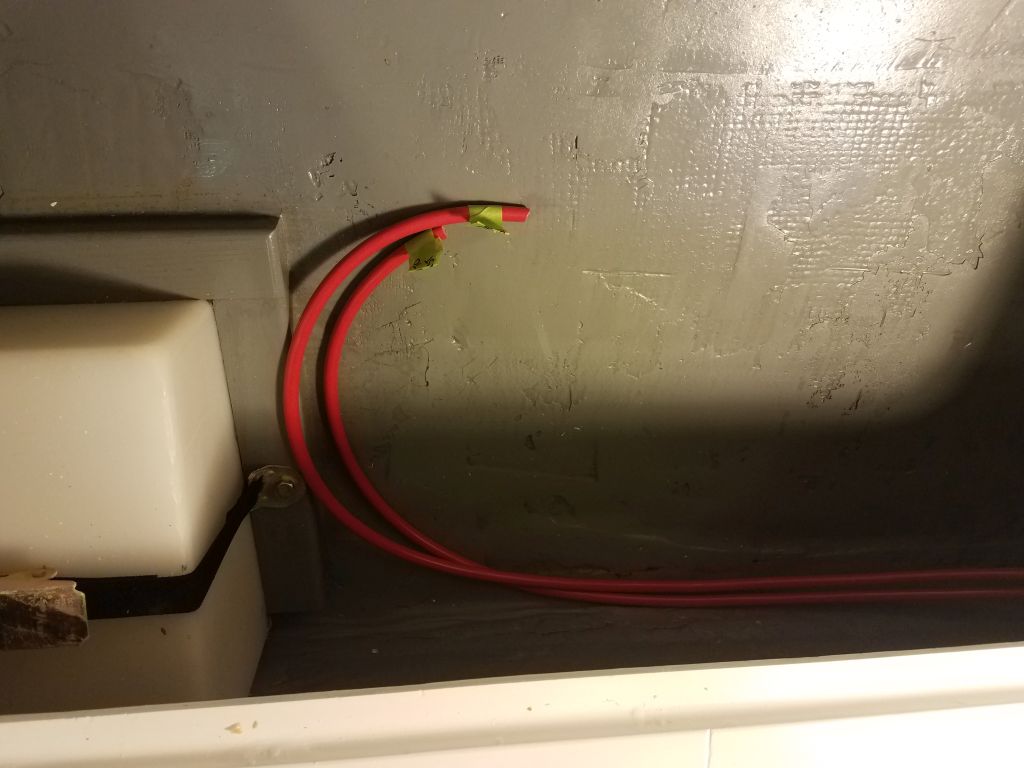
The distribution busses were to be on the downstream side of the main house shutoff switch, and I spent some time considering where the switch should be mounted.  It needed to be accessible, yet out of the way so as not to be an eyesore, and also required access to the back for installation and wiring.  The design of the molded forward cabin unit obviated all of my first choices, and eventually and at some length I settled on the forward end of the port settee base, which satisfied all the requirements.  I chose the port rather than the starboard side because it was a bit more out of the way (i.e. not as immediately visible in the finished boat with the table in place), and there was also a lot more going on in the starboard locker with the main wiring runs, and I didn’t want to add the extra clutter.

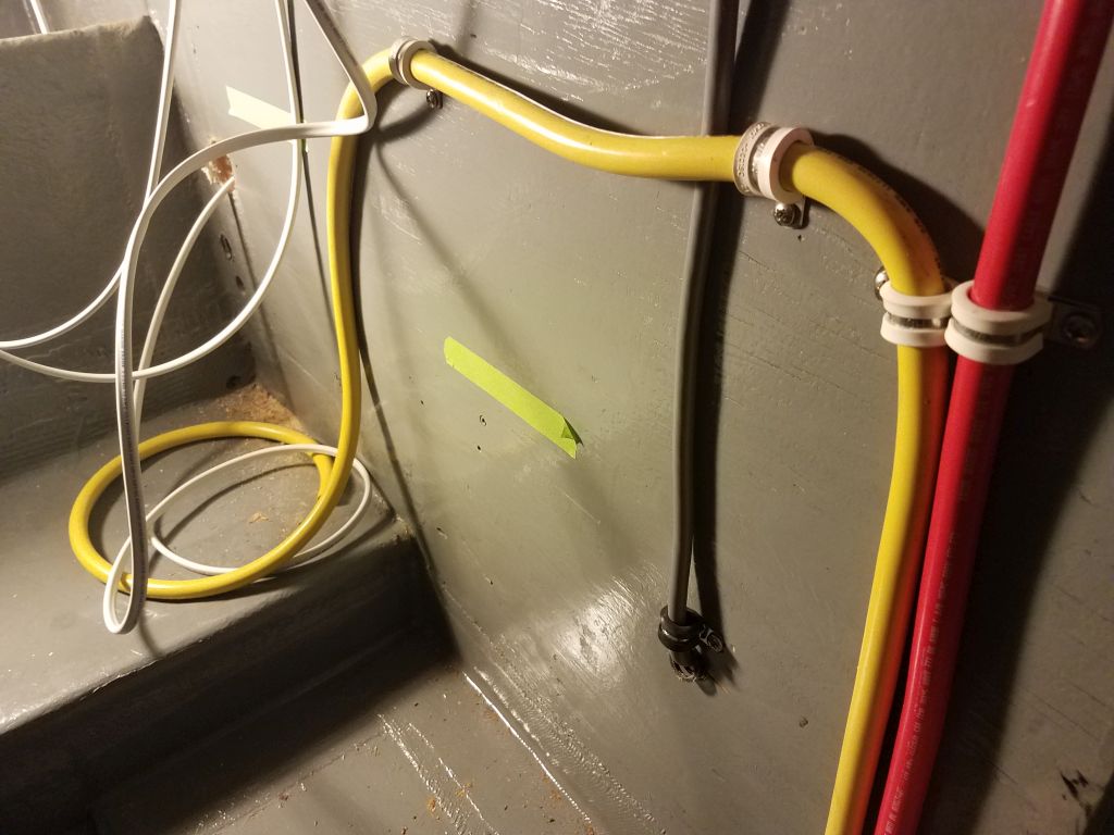
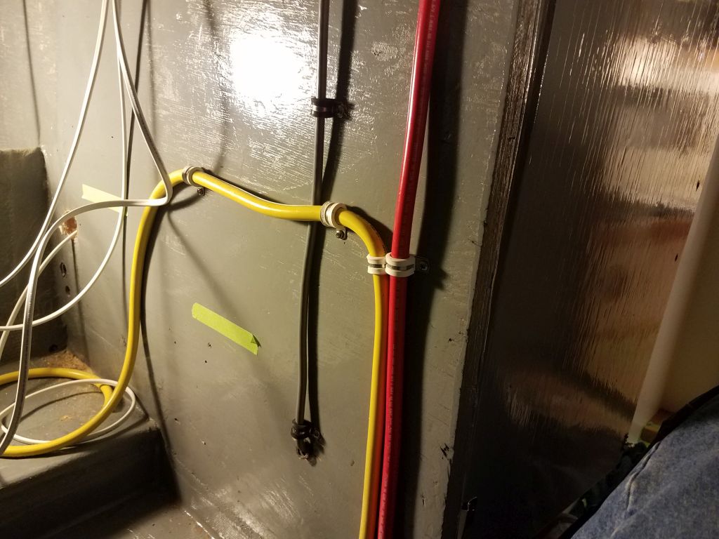
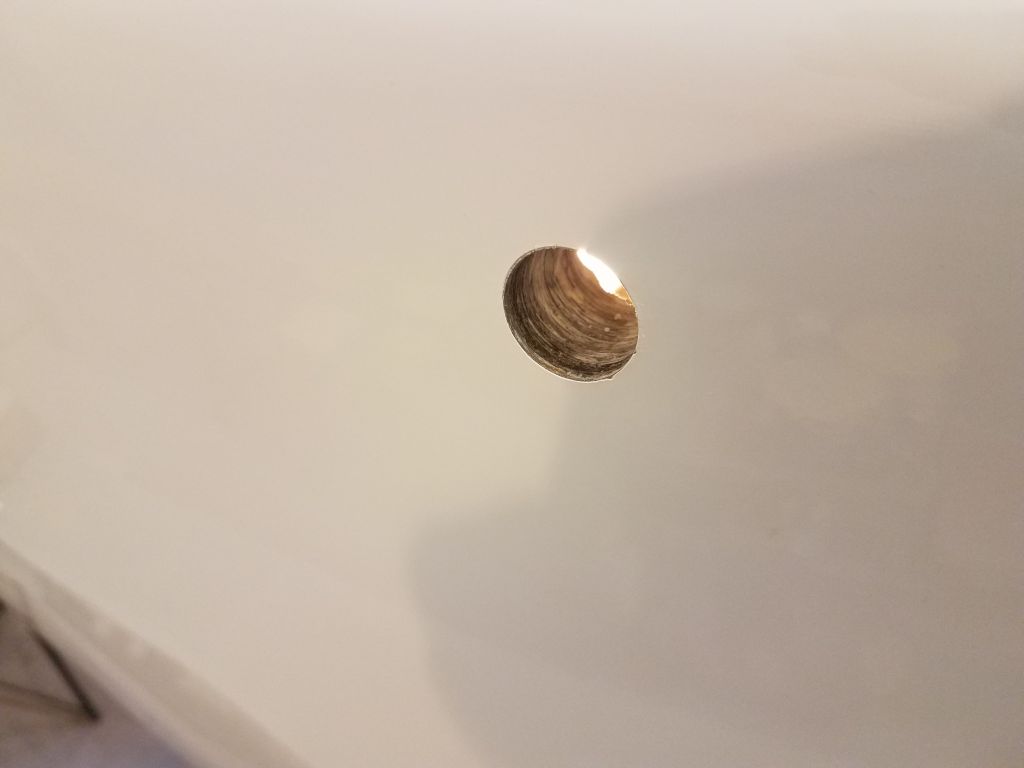
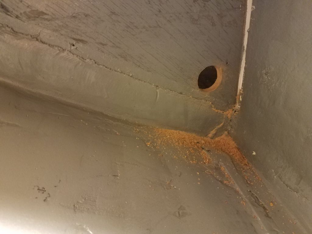
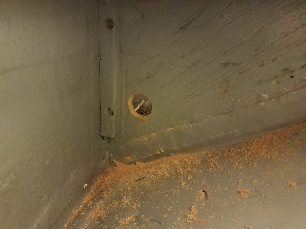
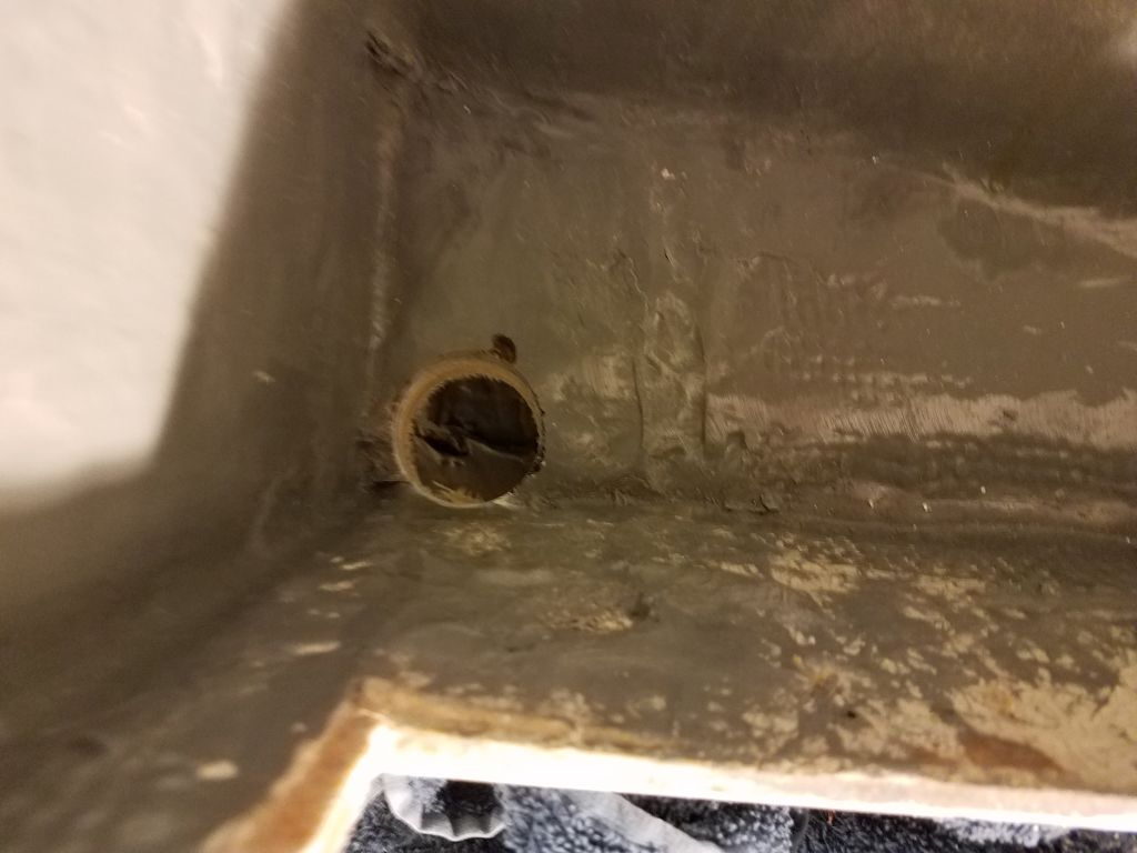
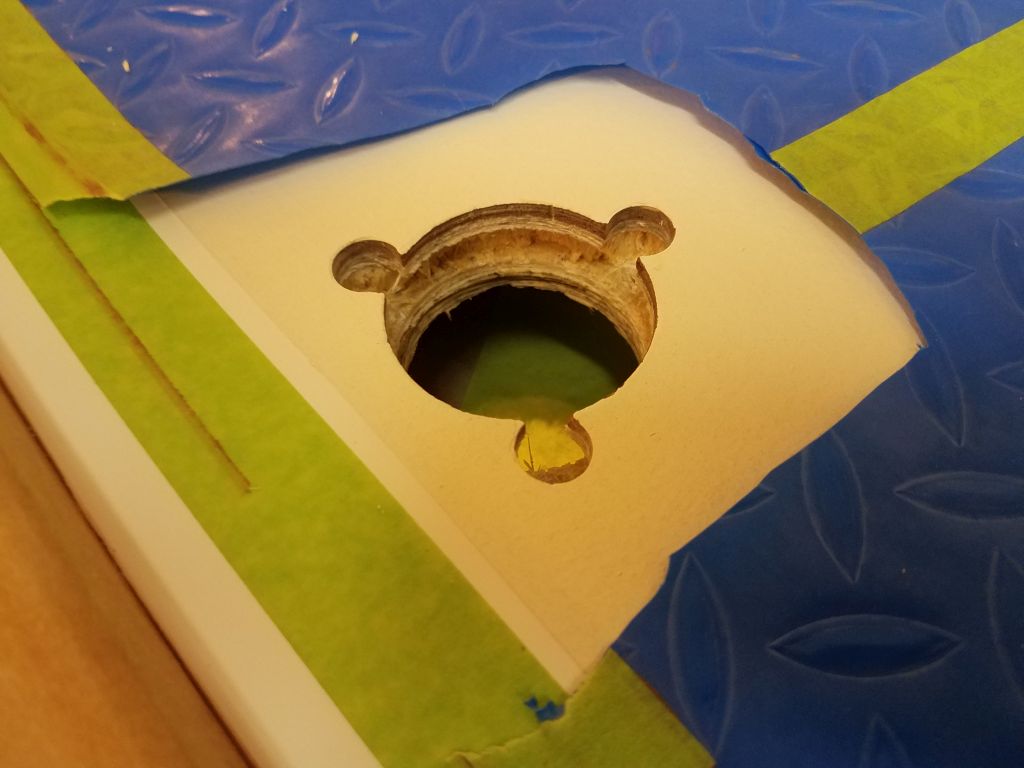
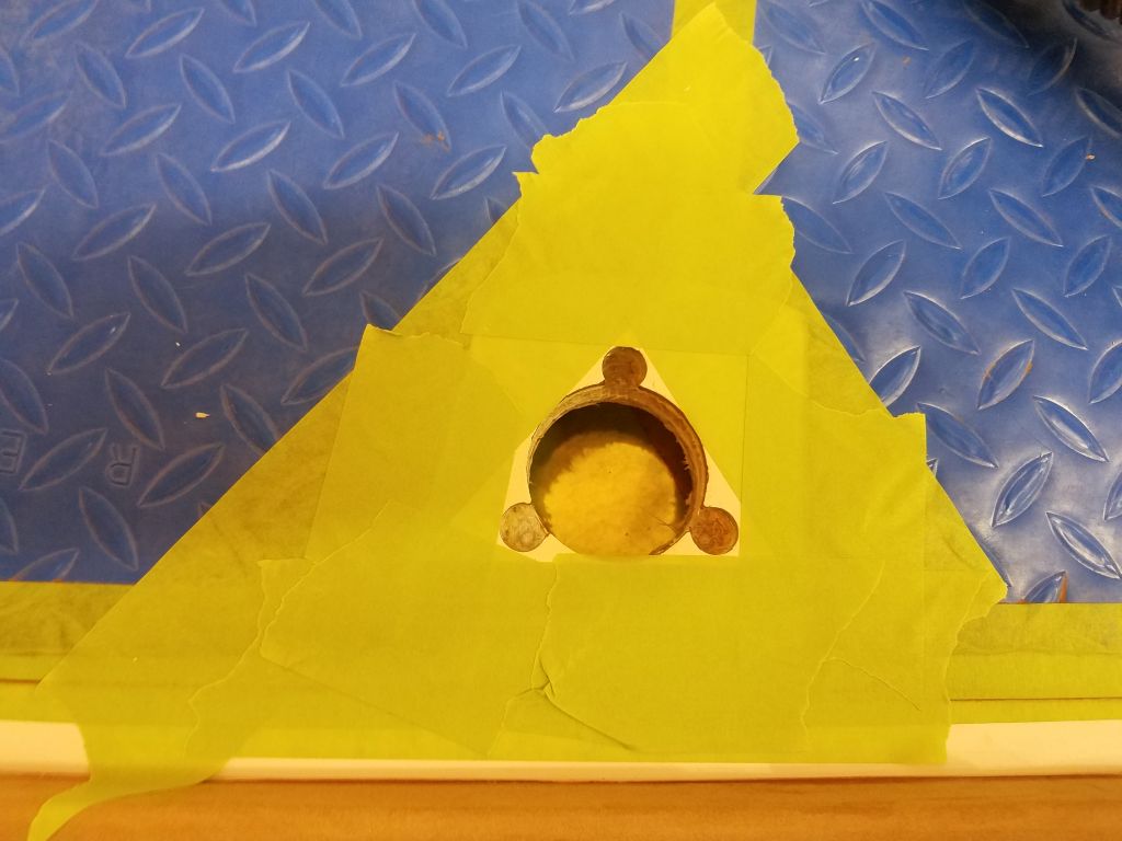
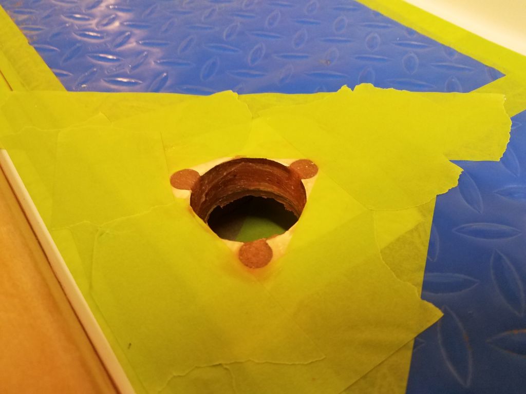
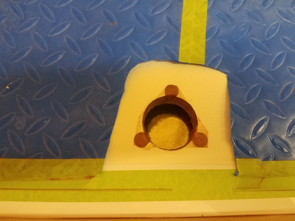
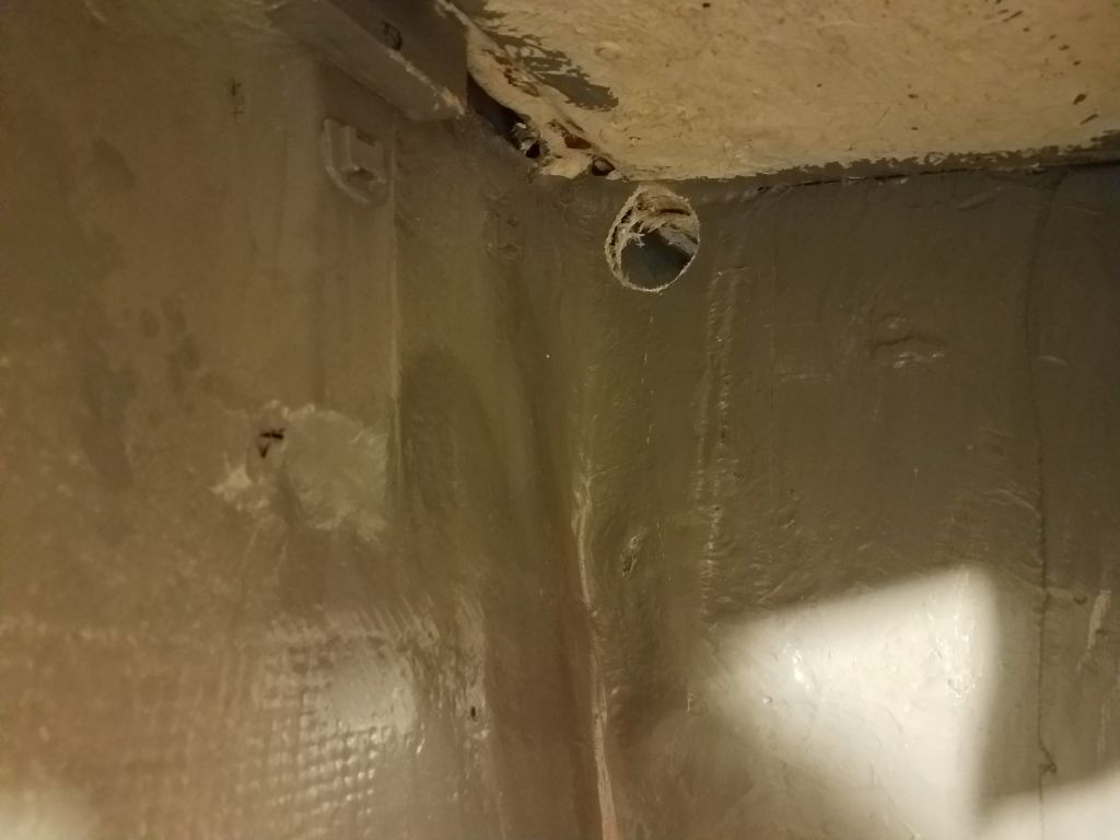
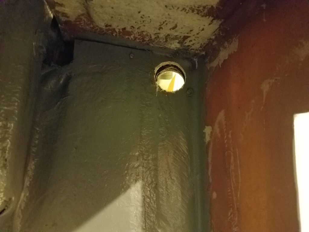
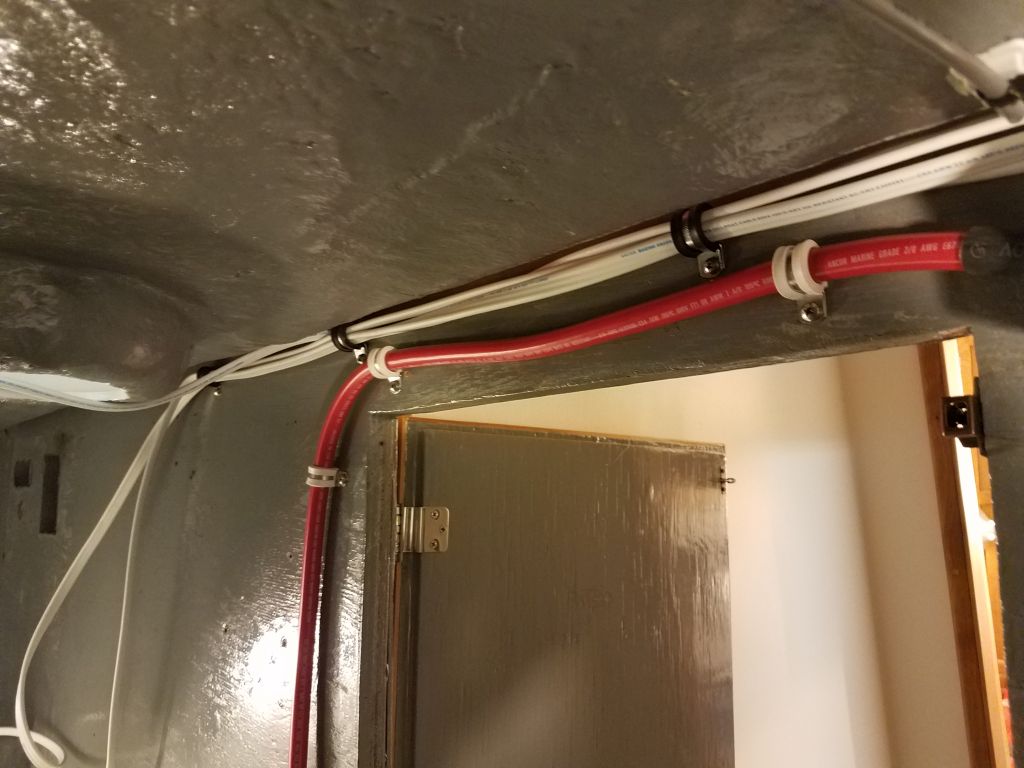
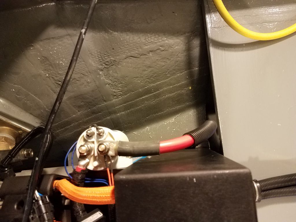
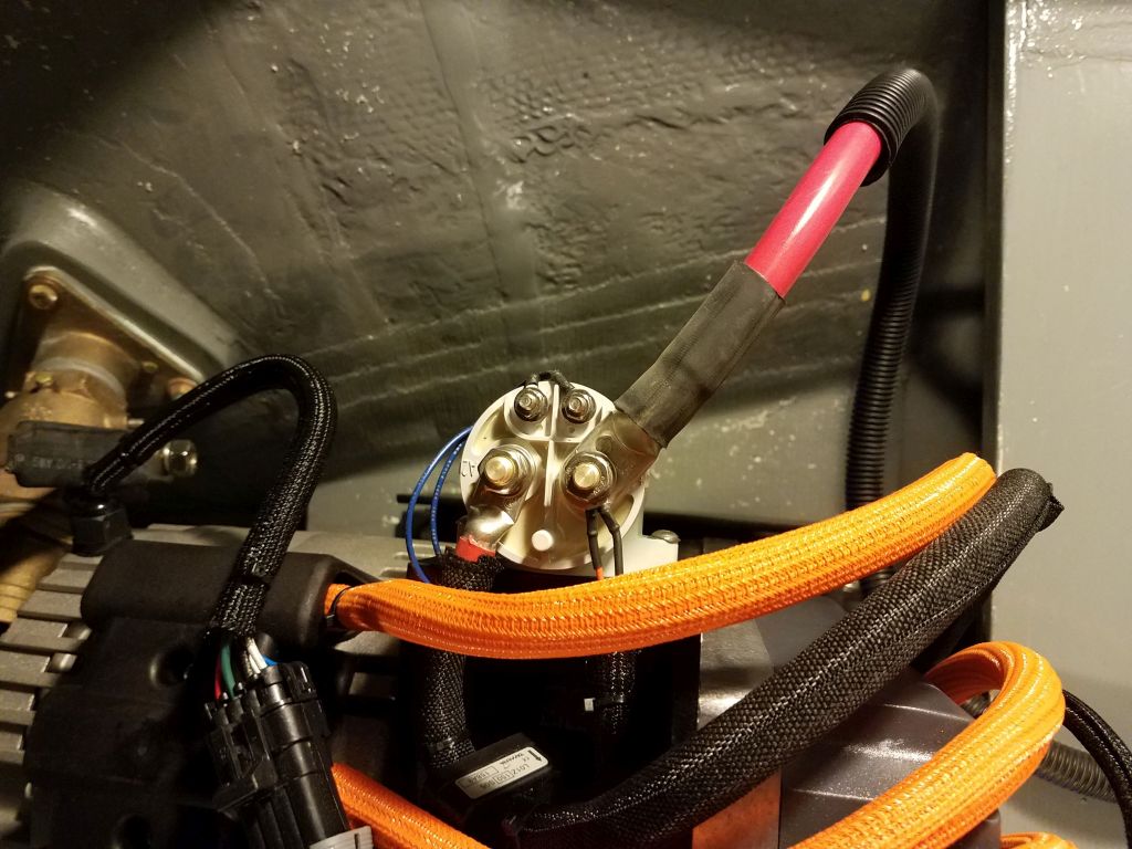
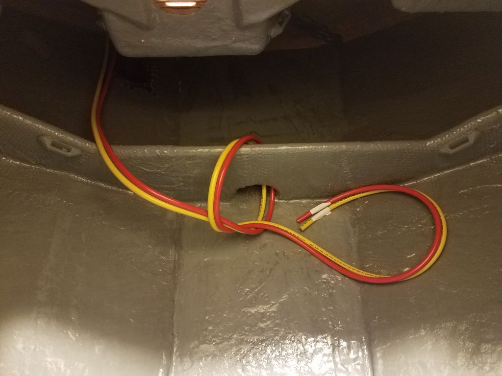
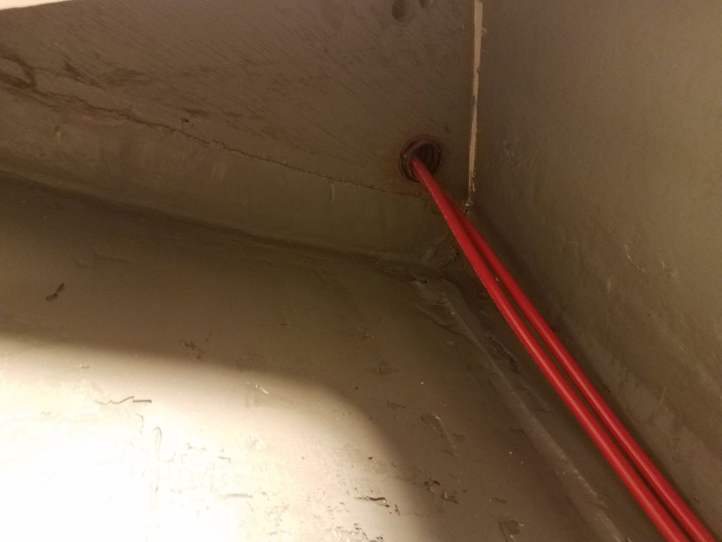
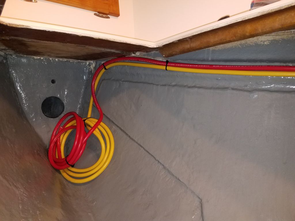
To this end, I ran red battery cables between the switch location and the battery location beneath the v-berth, preparing ahead for the switch installation, which would have to wait a day since I didn’t have the correct hole saw on hand for a flush installation.  The switch I chose was a small, basic one that fit the requirements of this system, and also happened to be the same as the one in the engine room for the electric motor.

To connect such items as electric bilge pumps, which needed to operate at all times regardless of the position of the main battery switch, I ran in a 10AWG cable from a small distribution buss in the electrical panel area; this wire would later be connected directly to the battery positive.

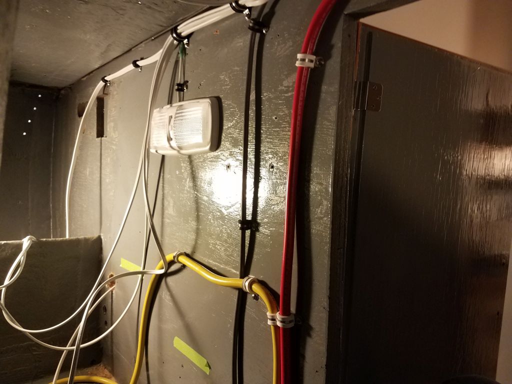
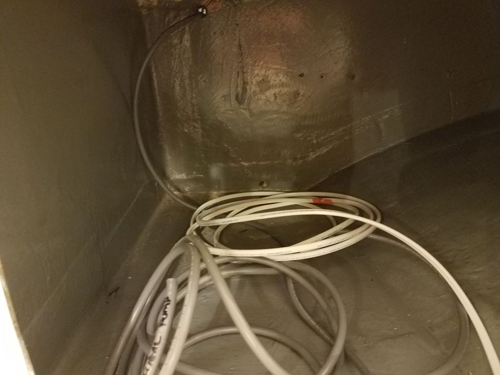
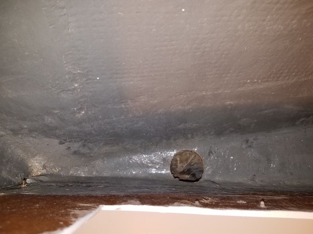
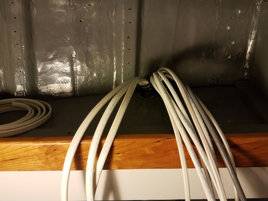
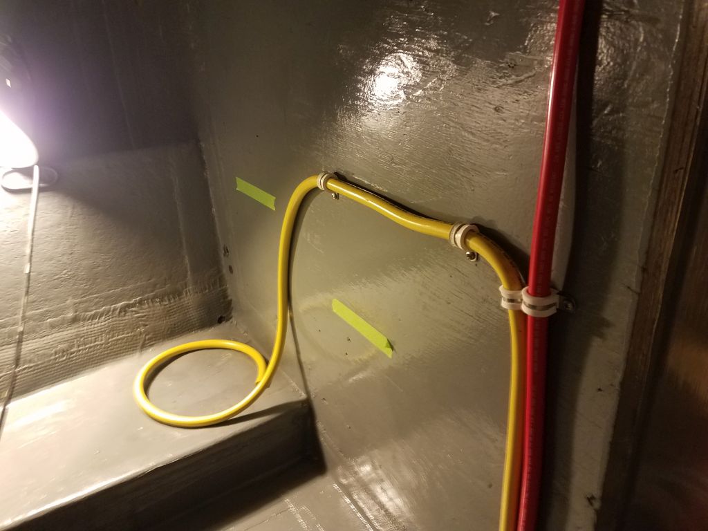
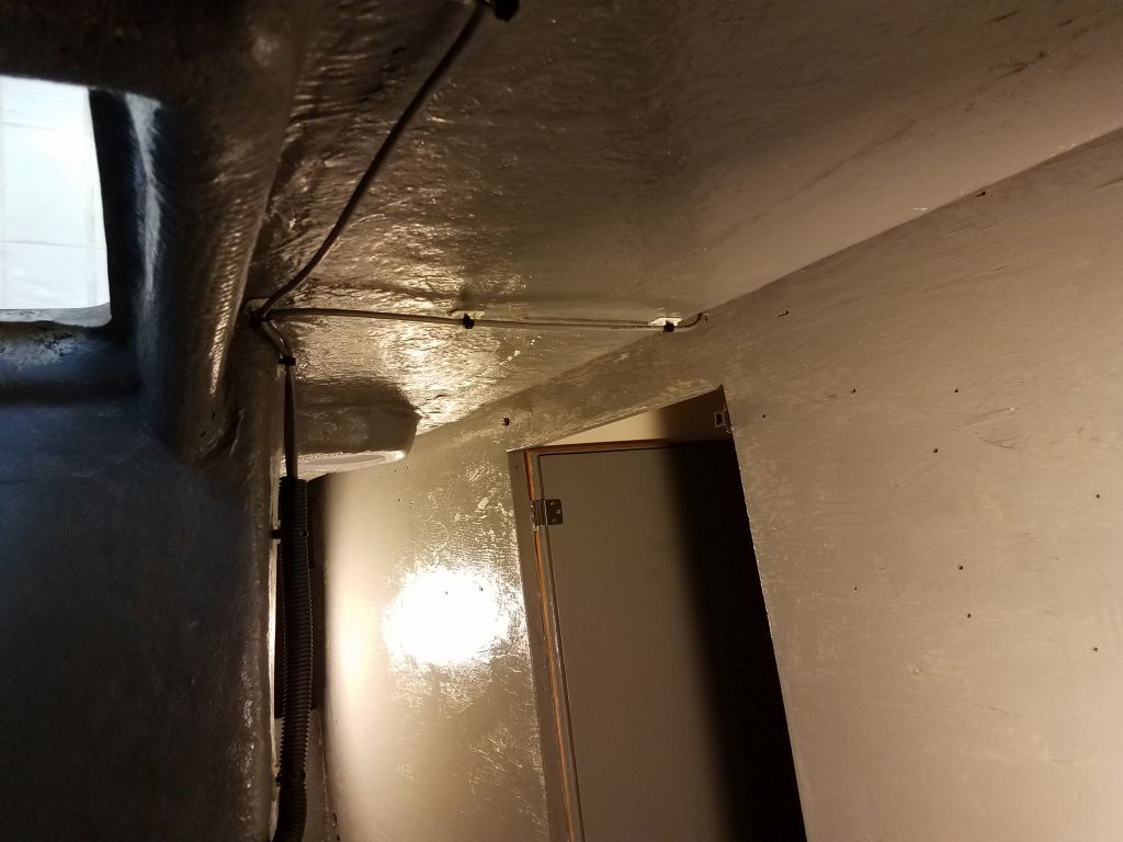
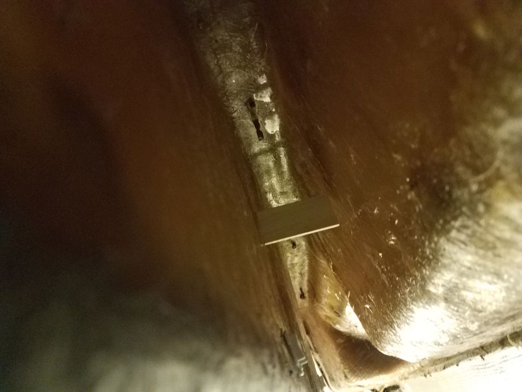
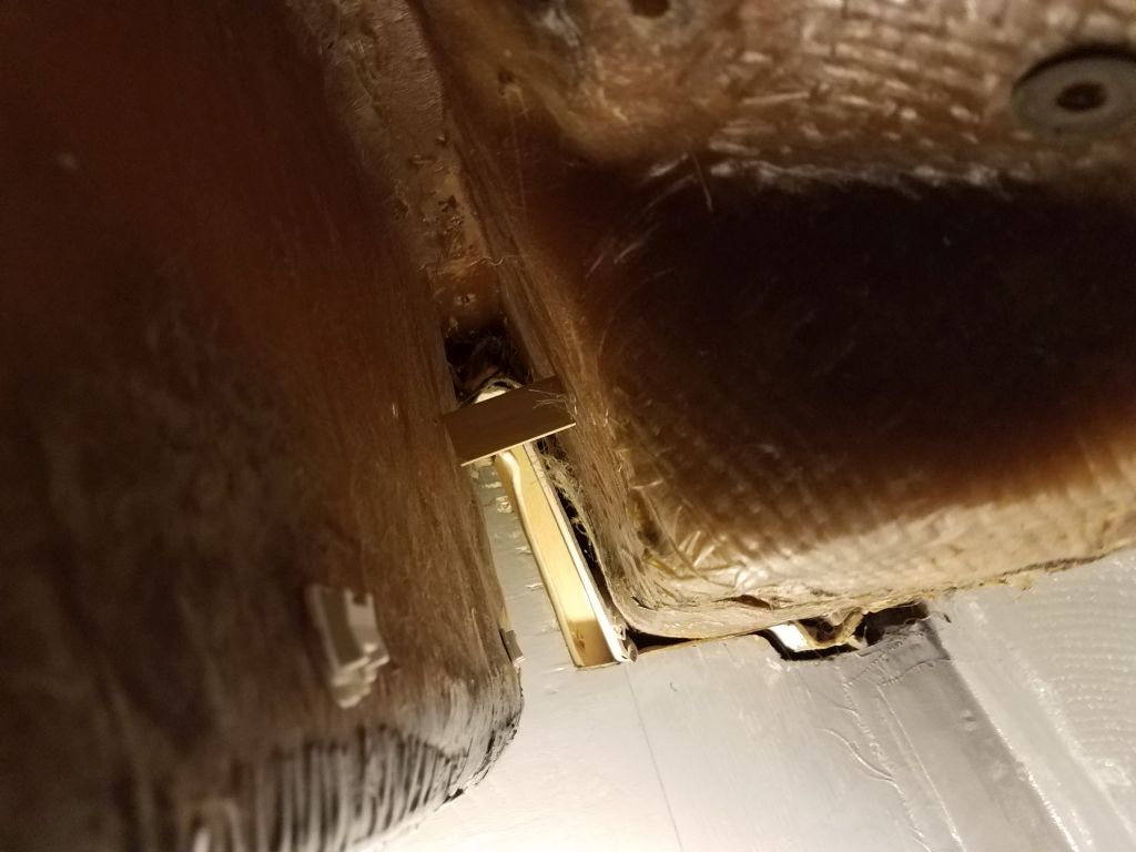
I had on hand enough heavy 2/0 battery cable to make the run forward from the battery distribution buss to the chainlocker, where these cables would eventually connect to an electric windlass.  I left the excess cable coiled up forward while I contemplated how best to run them into the tight chainlocker.

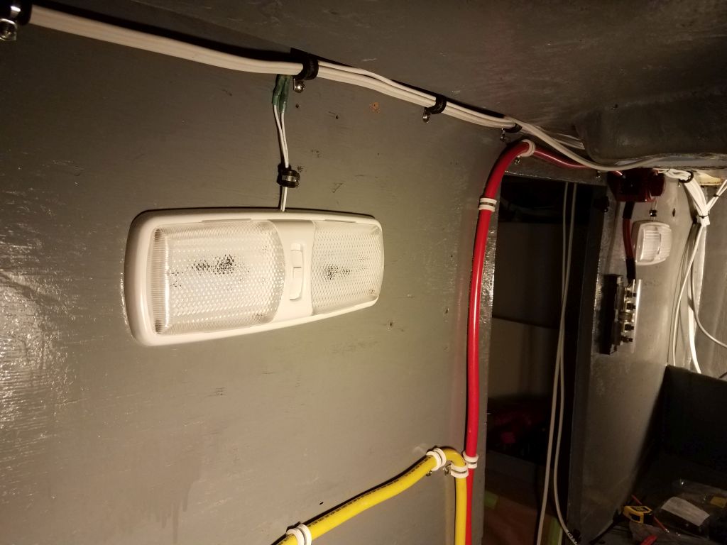
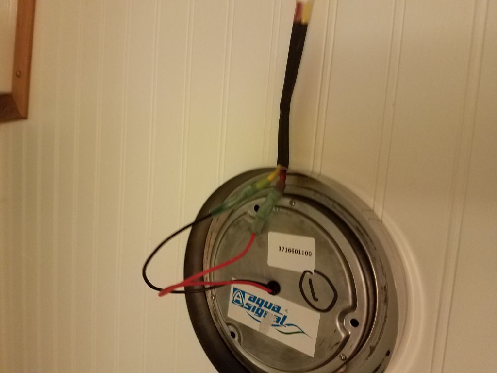
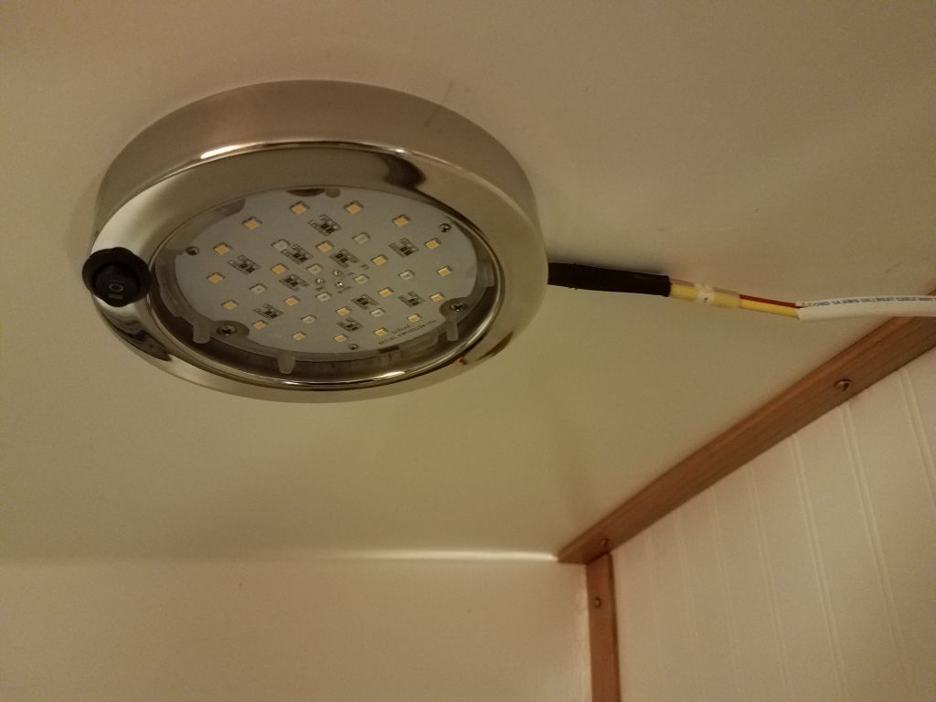
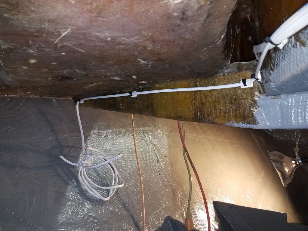
Two regular circuits also needed to run forward to supply the running lights, and a chainlocker light, and I now led these forward from the electrical panel, again leaving ample slack for their final runs and connection.

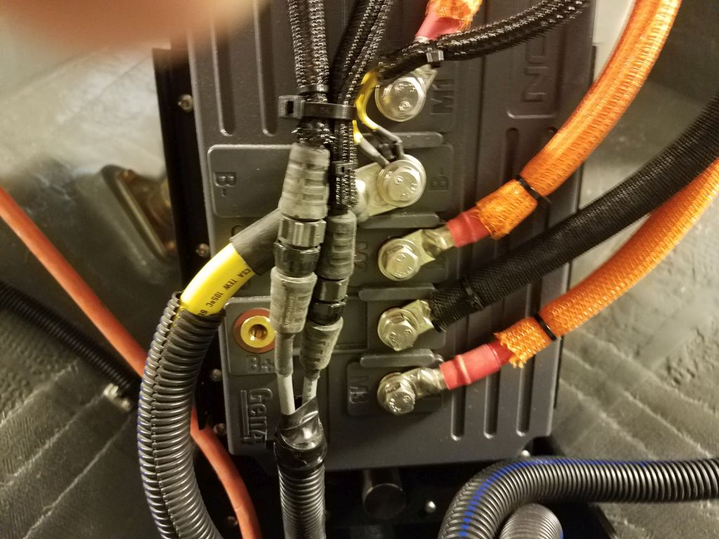
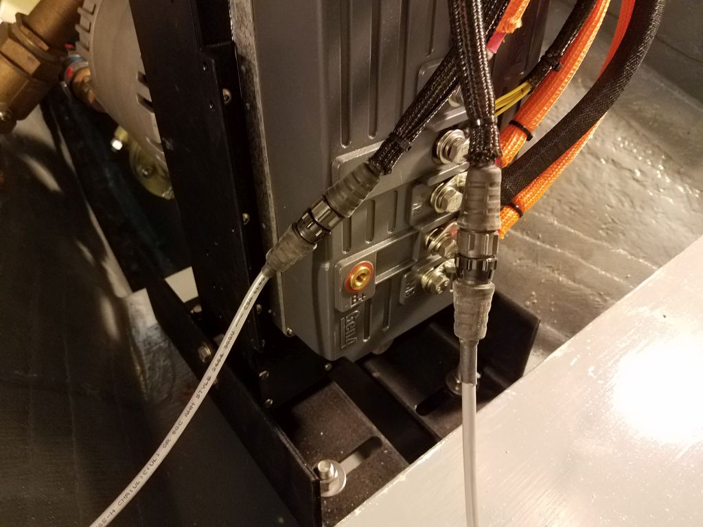
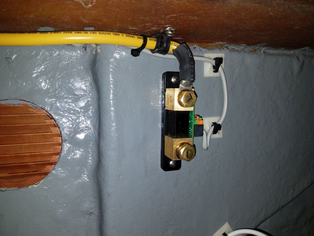
The last wires I needed to run along the route from electrical panel to the forward battery area were the control cable for the battery monitor (an Ethernet-type cable) and a 12/3 cable to power the house battery charger.  Also required for the battery monitor was a small shunt, which needed to be installed in the negative battery cable between the battery (not yet on hand) and the load side, which in this case was the negative distribution buss, so I made up that length of cable and installed it and the shunt in a convenient spot.

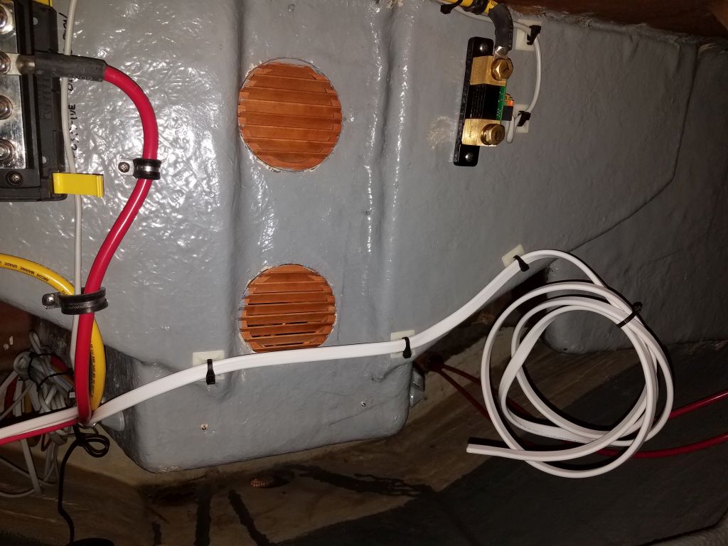
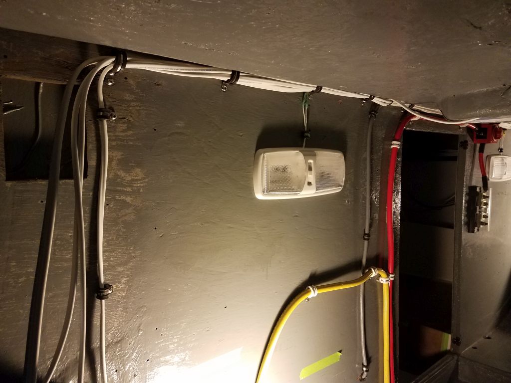
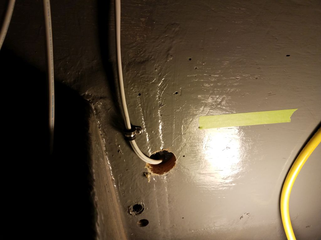
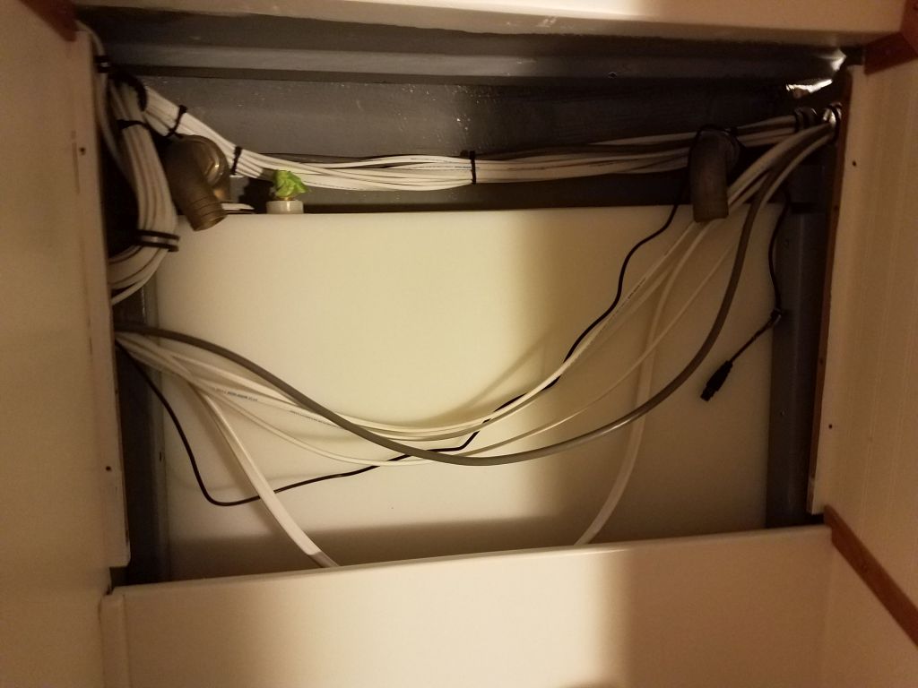
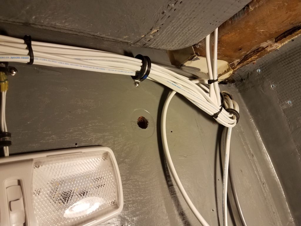
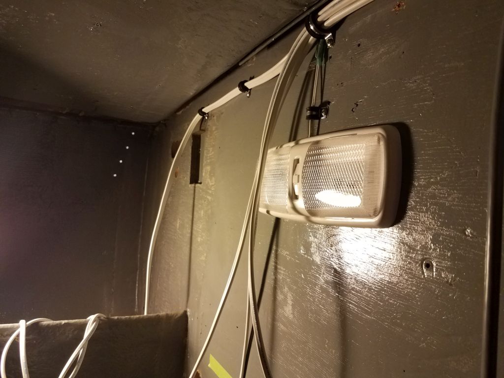
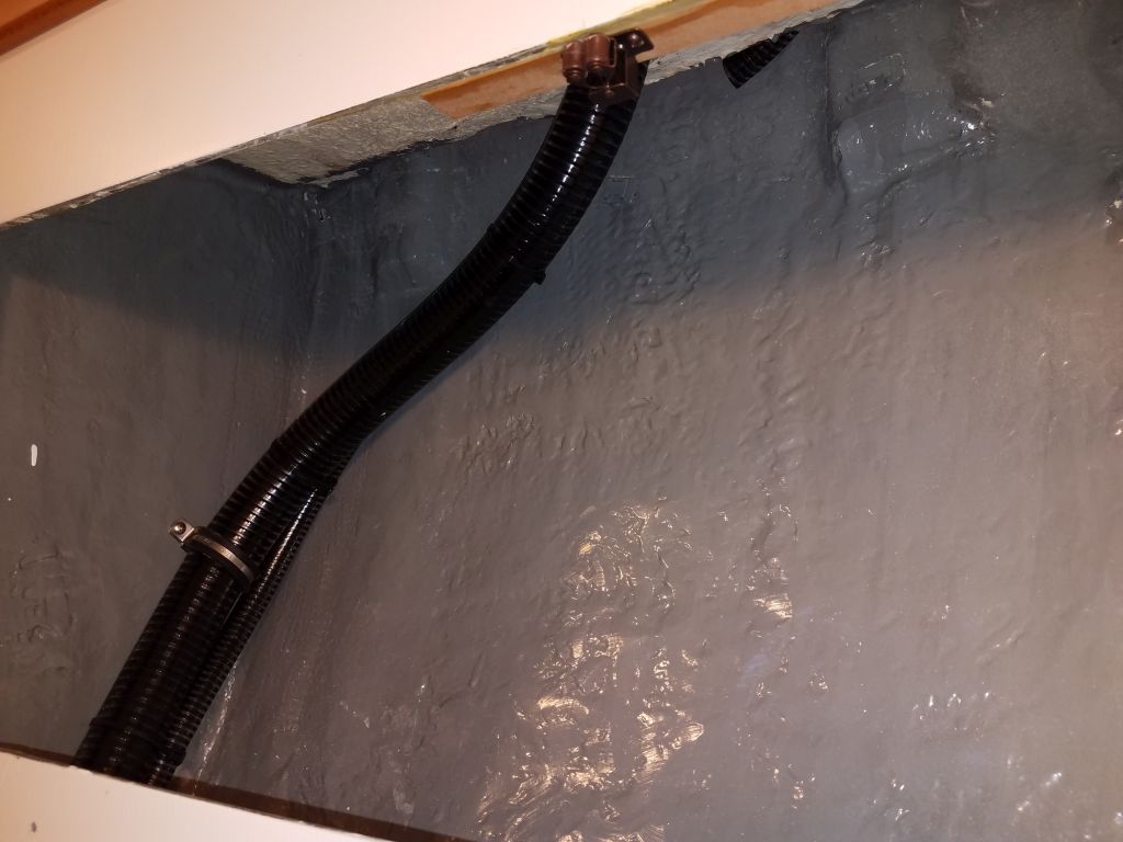
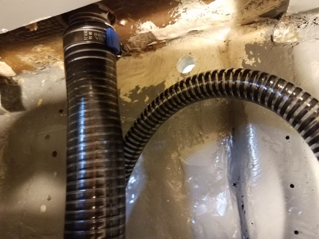
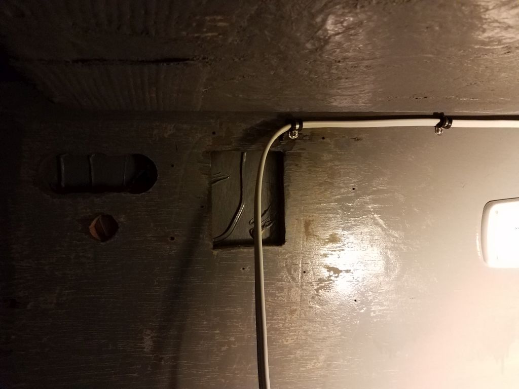
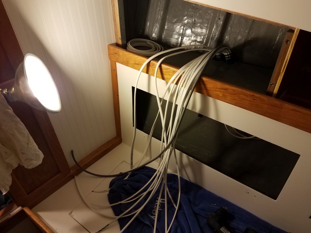
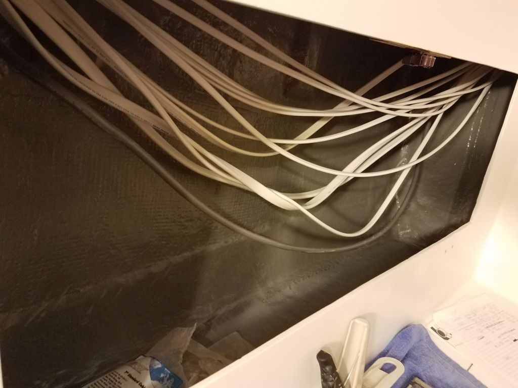
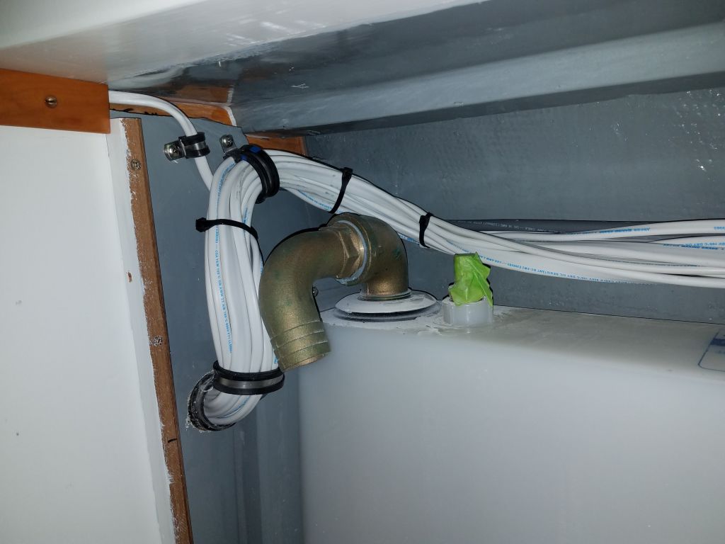
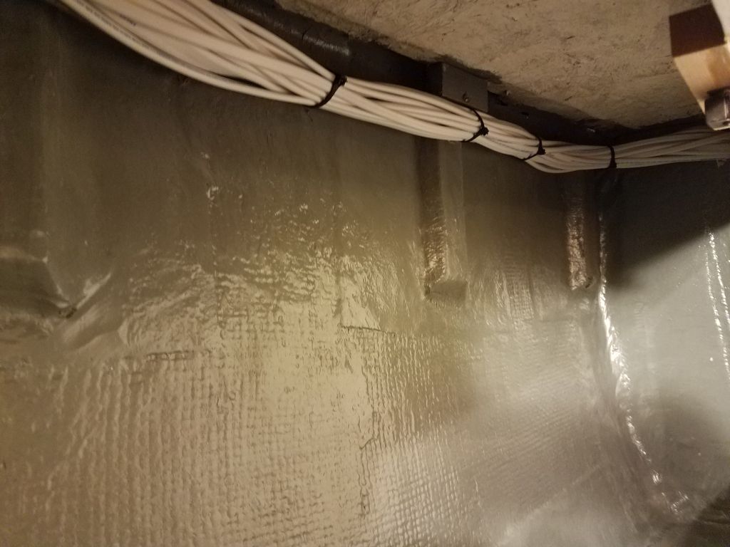
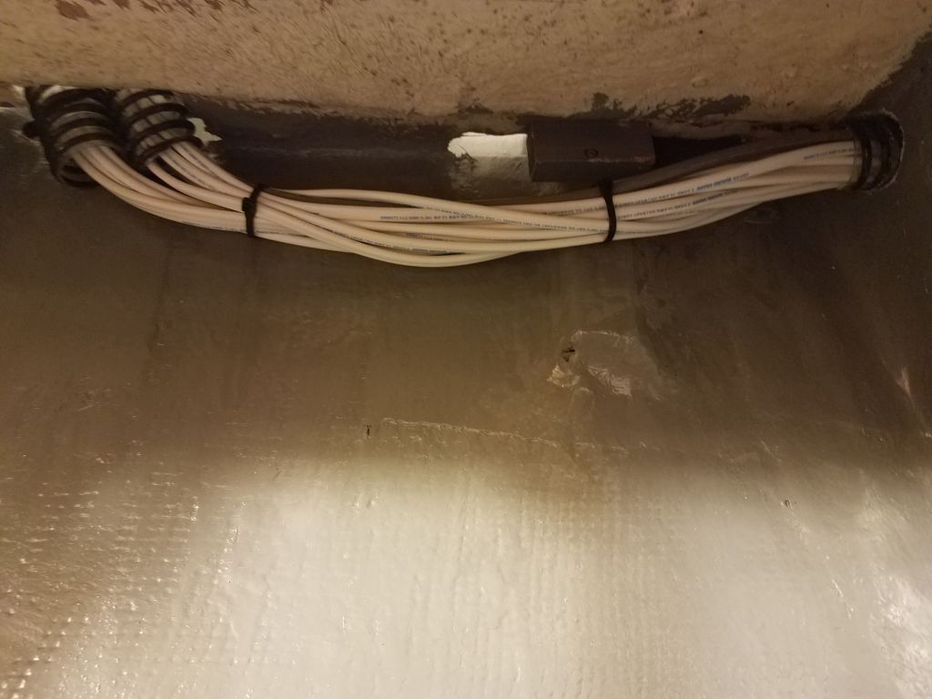
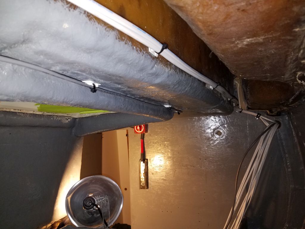
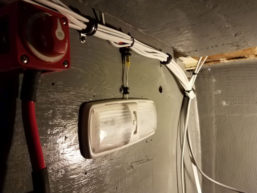
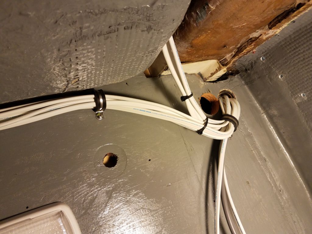
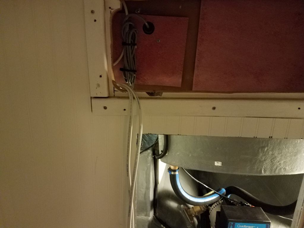
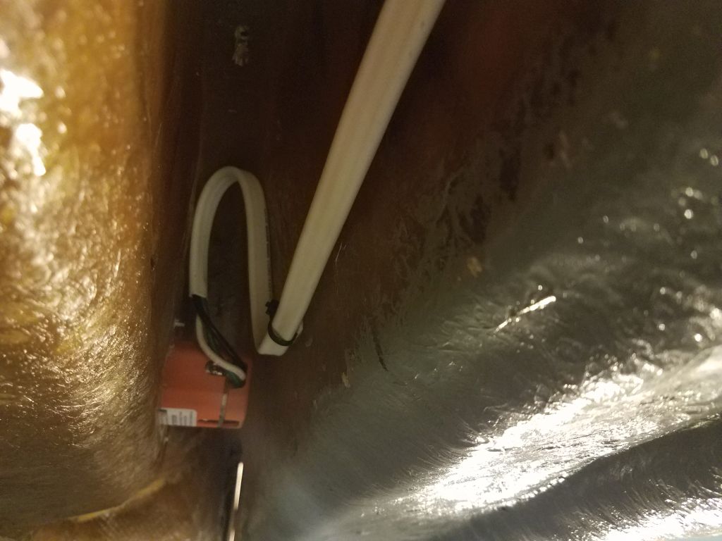
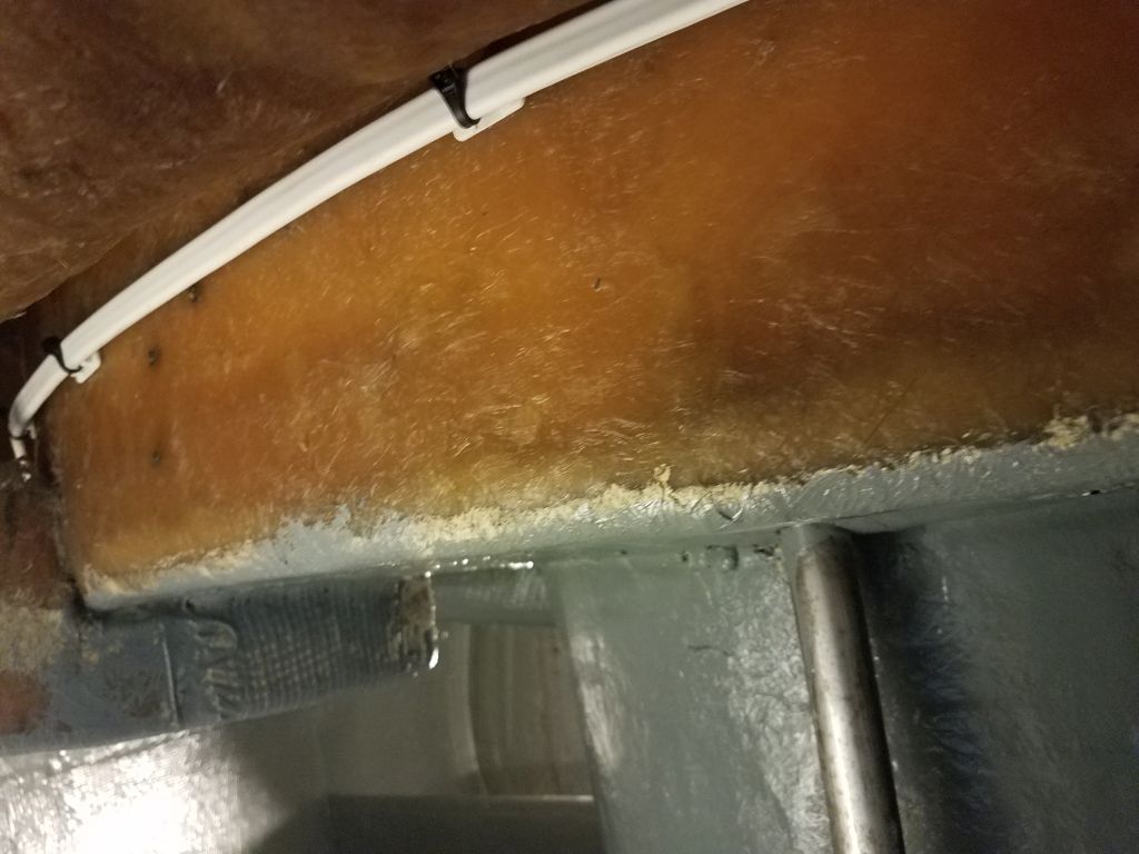
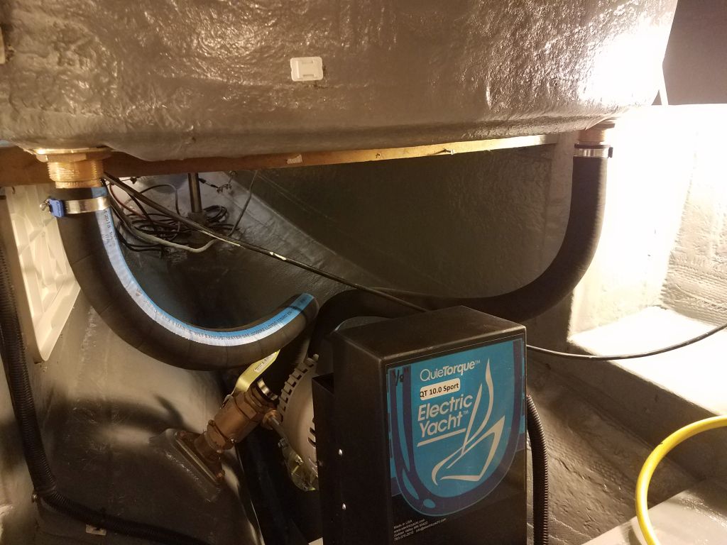
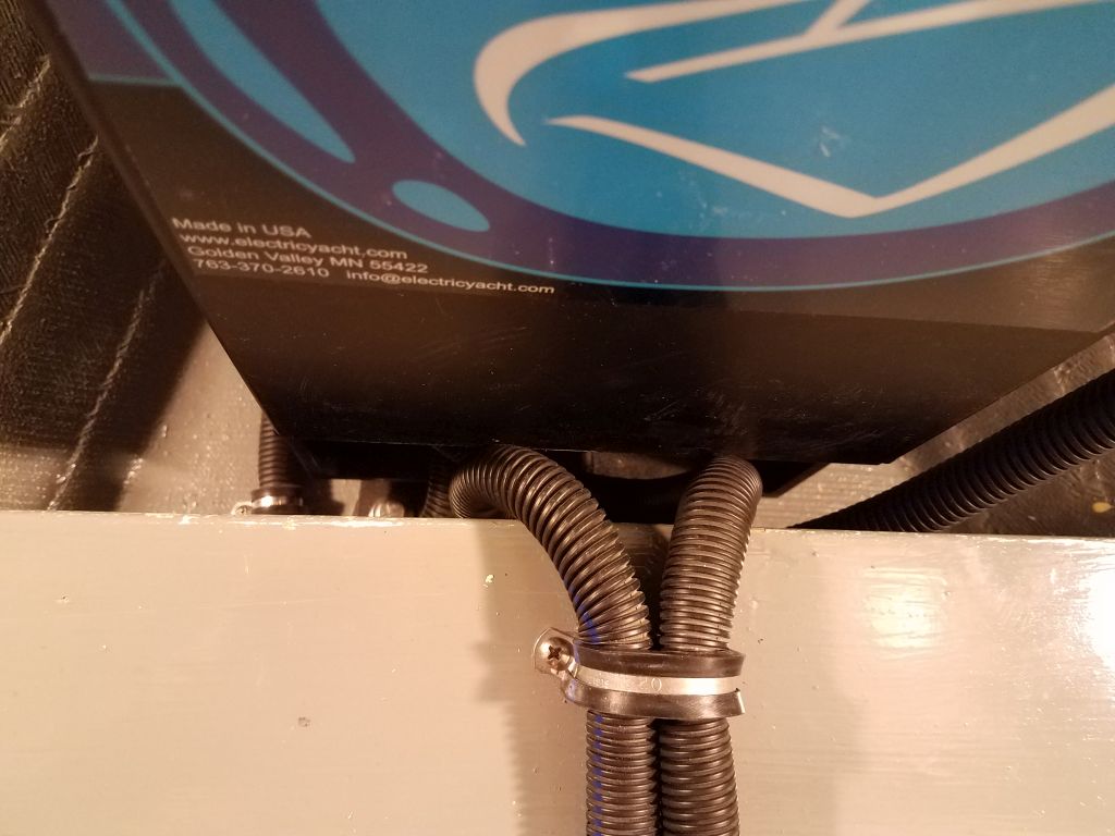
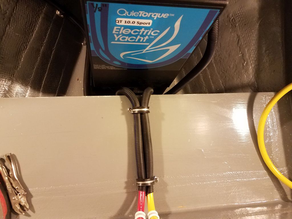
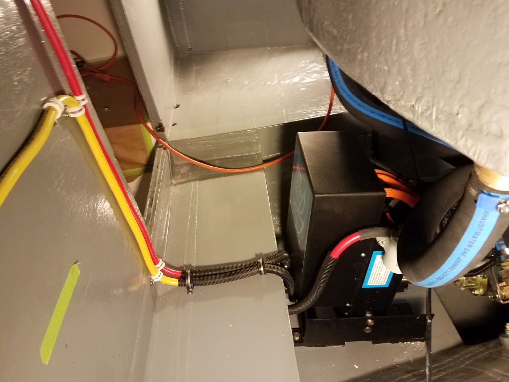
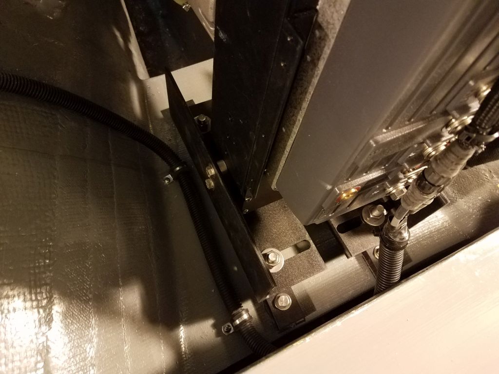
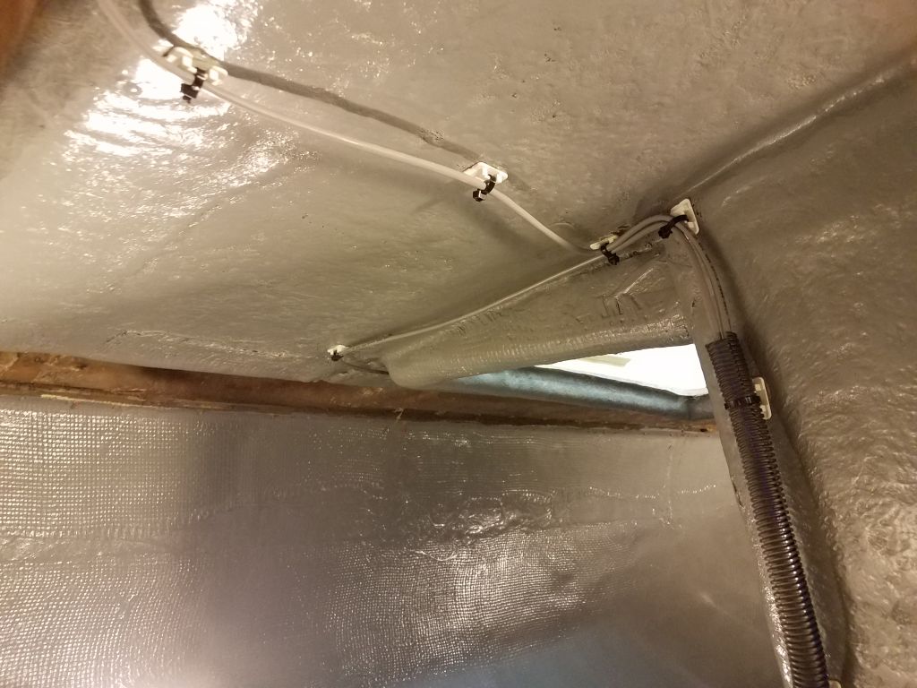
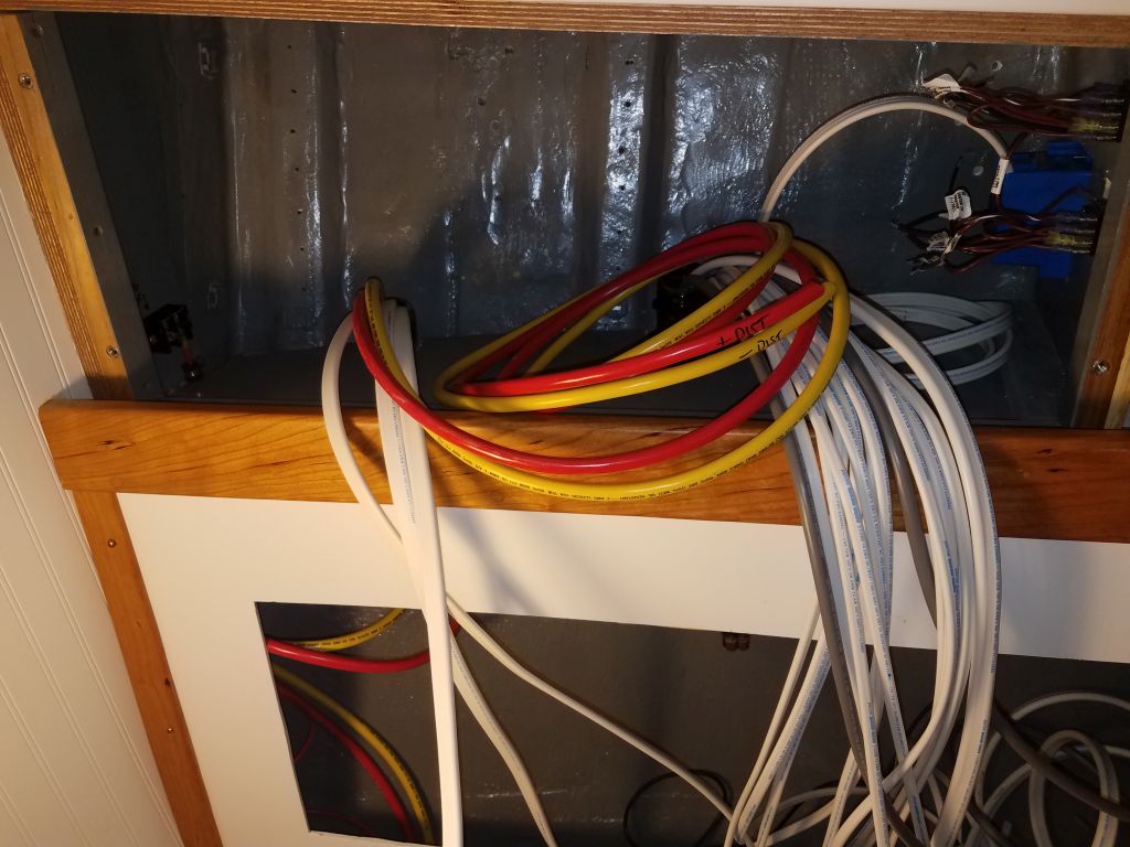
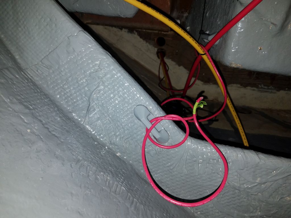
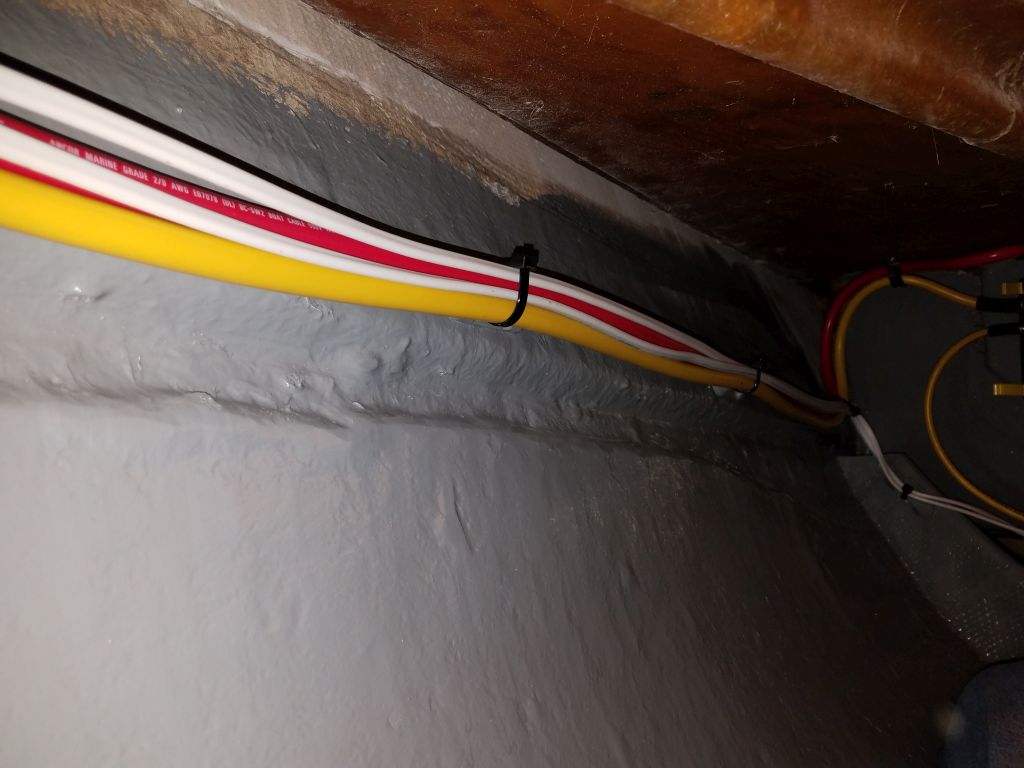
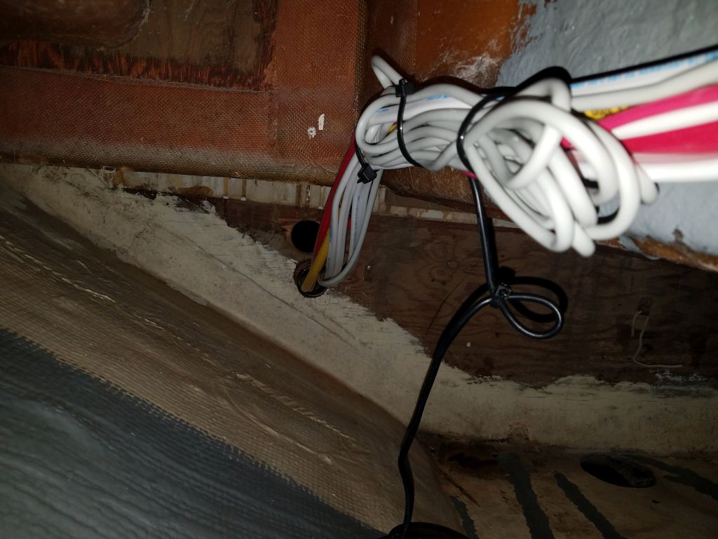
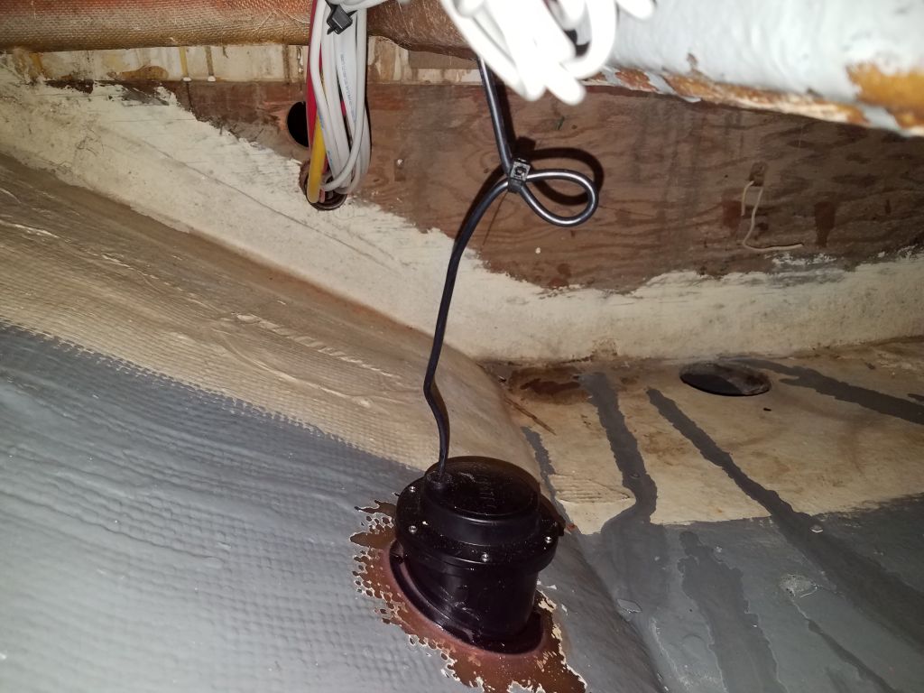
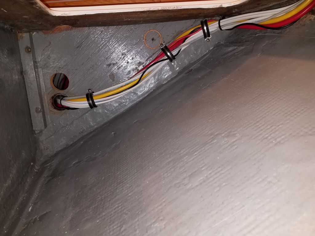
Now, working down and aft from these new installations, I secured the cables and wires as needed, using pre-installed mounts that I’d glued in long before during another phase of the project, and adding new mounts and supports as needed for the specifics at hand.  I secured most of the excess bundle of Ethernet cable for the battery monitor along with the other wire and cable runs leading aft, and secured the transducer cable into the bundle with a small stress-relief loop below.

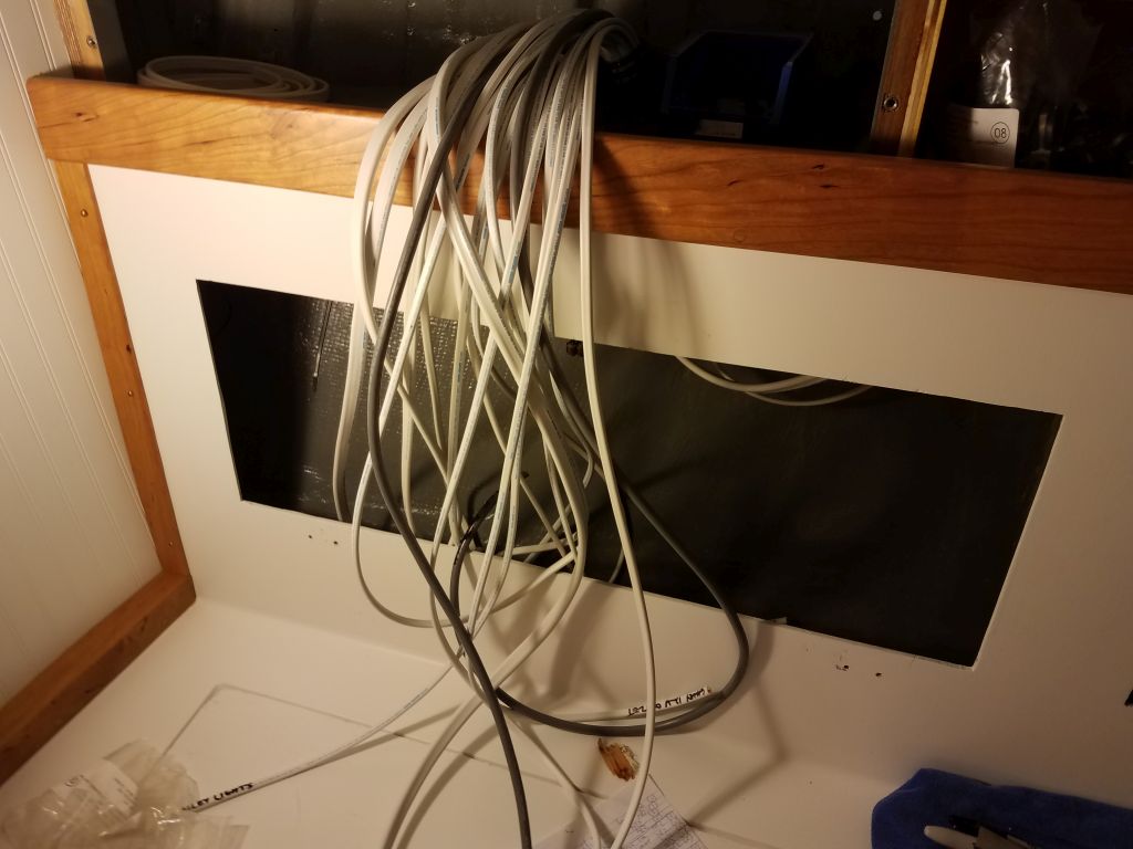
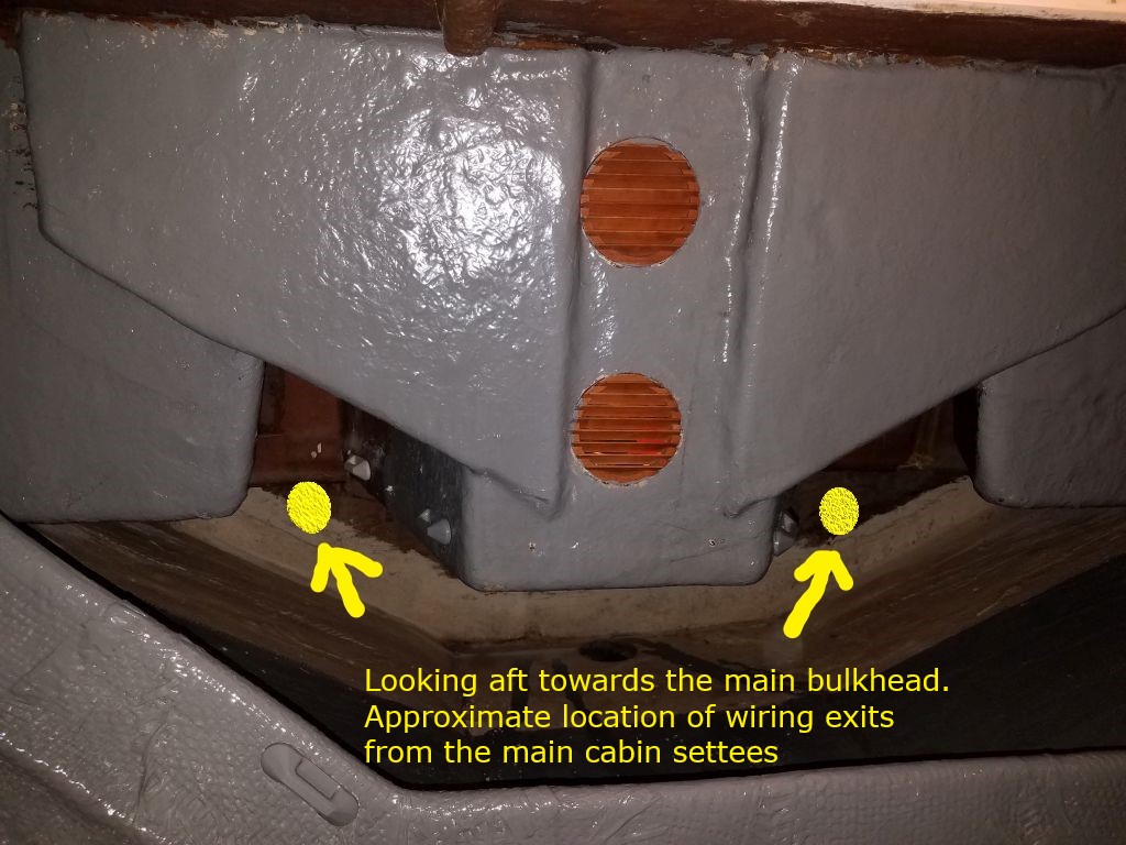
In the locker beneath the starboard settee, I pulled in the remaining slack and secured this large cable bundle in several places along the base of the bulkhead and leading to the wire chase to the settee back before the end of the day.  This left me with a bit of organized chaos at the electrical locker and in the settee back, but I’d continue the organization and securing next time before continuing with the final wire runs required over to the port side of the boat.

Total time billed on this job today:  8.75 hours

0600 Weather Observation:  20°, clear. Forecast for the day:  Sunny, 30°

Scupper 202

Friday

In the engine room, I finished up securing the new wires in their run across the forward, upper edge of the space, and leading the larger wire pair for the new potable water pump (12 AWG to accommodate the amperage draw) down the bulkhead and through the conduit I’d installed earlier into the space beneath the galley. (The conduit is there, but slid forward since it wasn’t yet secured.)  I left the other two circuits unsecured at their very ends pending final leads and connections to the galley 12-volt outlet and galley lights, which installations would come soon.

To accommodate the requirements of the fresh water flush toilet the owner selected, I chose a hefty water pump with more than ample capacity.  After preparing the hose fittings on the bench, I brought the pump up to install it in the galley.  However, I found that the size of the pump, including its end fittings, made it an awkward fit anywhere on the shelf beneath the sink, which is where I’d imagined installing it, and after trying various locations I finally settled on the bulkhead at the back of the space, not where I’d hoped to install it, but workable for wiring, hose runs, and maintenance access while keeping the rest of the compartment more or less free for storage.

With the pump finally secured to the bulkhead, I finished up the wiring and hose runs, incorporating a tee fitting to service the galley faucet above, and with the discharge line continuing back aft and through into the engine room where it would ultimately service the cockpit shower and fresh water toilet.  I led in the supply line from the water tank and secured all the hoses and wiring as needed to complete the installation.  There was access to the pump and the intake filter through the drawer openings, though for installation I removed the cooktop from the countertop, which provided good access.  I’d continue the hose runs in the engine room soon, but required another hose fitting that I didn’t have on hand.

That whole process took up the entire morning, so in the afternoon I turned to the electrical panel area, where I needed to install some fittings in the aft side:  two bilge pump switches and a 110-volt outlet.  I wanted to do this now before I got started on any of the final wiring inside the locker.  It might have been nice to cut these openings before the little bulkhead was permanently installed, but that was a different phase of the project many months before.  Since I only had one chance to make the cutouts right in this finished bulkhead, I chose to make a layout template to ensure I got the holes cut just so, so working from an initial paper template I made a template from some scrap 1/4″ plywood that served my purpose to replicate the size and shape of the bulkhead.

After making some templates of the cutouts required for the bilge pump switches and outlet box, I laid out the plywood template accordingly, taking into account various constrictions on the space, and cut the openings as a mockup.

After covering the bulkhead with tape, I transferred the holes from the template onto the tape, then cut out the openings as needed, which allowed me to install the switches and the 110-volt outlet, to which I connected a short length of 12/3 cable that I’d presently lead back to the AC service panel when I got to that stage of the wiring project.

After straightening up the boat and my tools and supplies, I called it quits for the day, and for the week.

Total time billed on this job today:  7.5 hours

0600 Weather Observation:  21°, partly clear. Forecast for the day:  Mostly cloudy, chance of drizzle late in the afternoon, 41°

Scupper 201

Thursday

After an early morning commitment elsewhere, I got back to the shop in time to finish up the installation of the solar vent in the companionway before lunchtime.  This was a straightforward installation with sealant and three screws.  Because of the lack of clearance beneath the hatch when it was installed, I couldn’t use the provided trim ring at the underside of the hole, so later I planned to come back and touch up the paint a bit.

Now that the vent was installed, I could install the hatch for good by reinstalling the two stainless steel tabs that held it in place by sliding in grooves in the companionway rails.

I spent the rest of the day working on the electrical system, starting again with the transducer.  I wanted to give the epoxy some additional cure time before I filled the reservoir with the required liquid, but to help me run the transducer cable I temporarily installed the transducer with a couple of its screws to hold it in place.

Before beginning the cable run, I drilled another set of holes as needed in the settee back and holding tank area to accommodate this and additional cable runs alongside the full run of cables from a few days earlier.  I was pretty sure from the getgo that the supplied length of transducer cable wasn’t going to be enough to travel the convoluted distance between the transducer and the display, and I soon confirmed this as I led the cable loosely through the new conduits leading to the starboard settee and wiring area, then aft into the holding tank compartment, which was as far as the cable would reach (allowing ample slack in order to be able to later secure it properly).  I ordered an extension cable that would allow me to lead the cable the rest of the way to the location of the display, but I’d have to wait a few days for its arrival.

Meanwhile, I led a series of additional cables aft along the starboard side, as I’d decided that it made the most sense to string the wires needed for the galley lights, galley-mounted 12-volt outlet, and the potable water pump through this route instead of through the forward/port route.  Since I already needed another conduit opening along the starboard side to accommodate the transducer cable and some large wires to power the electric head, there was plenty of room to run some of the other wires which, upon reflection, seemed the best route after all.   I strung these wires leaving ample slack that would allow me to clean them up and secure them in place once all the new wires were in place.  I also ran the power cables for the second electric bilge pump, which I planned to mount in the bilge beneath the galley/head area, which was accessible through a hatch in the galley.

With all these new wires leading into the starboard side of the engine room, I thought my cable runs on this side were now complete, and at the end of the afternoon I finished up by beginning to secure these cables inside the engine room, using the cable run I’d already installed during the earlier wiring session.  There were still a few wires from the first runs that weren’t yet made up, including a large triplex for the eventual 48-volt battery charger, plus wires for the diaphragm bilge pump I planned to install on a platform in the engine room, but for now I left those alone for later attention.  To accommodate the new wires running across to the port side, I removed the existing wire clamps as I went and replaced them with larger ones as needed to hold the larger bundles, and by the end of the day I’d secured and cleaned up the new wiring in the engine room as far to port as I could reach easily from the access door, leaving just the final couple feet to take care of later from the port cockpit locker.

I also drilled a hole into the galley sink compartment to accommodate the 12/2 wire for the electric water pump, and this new opening would also allow passage of the water hose later.  For the new bilge pump, which would be a larger pump designed more as an emergency, larger-capacity pump to kick in only if the water level got high enough, I led the wire in to the upper reaches of the cooler storage compartment beneath the galley, leaving lots of loose wire there for eventual routing to the bilge and the pump once I had it on hand.

Total time billed on this job today:  5.75 hours

0600 Weather Observation:  21°, clear.  Forecast for the day:  Sunny, windy, 26°

Scupper 200

Wednesday

Things that take a long time:

  1.  Working in boats with molded liners
  2.  Doing anything with a hole saw
  3.  Hose

Any project combining this holy trinity is bound to take inordinate amounts of time, and so it proved to be once again as I continued where I left off with the water tank fill and vent runs.  Finishing up the installation of the new water deck fill was straightforward enough to start though.  With the epoxy cured in the new opening and around the screw locations, it didn’t take long to prepare the fastener holes (drill and tap for #10 fasteners, then mill the countersink at deck level) and install the fitting in a heavy bed of sealant.

Inside the boat I found that the molded liner hid most of the fill neck, so I expanded the opening that I’d drilled previously, ultimately cutting out a large section of the liner inside the locker above the port settee, which was hidden from view so the liner didn’t make any difference.  I actually cut the liner in several increments, enlarging each time, to finally provide better access to the after chainplate, the tank fill neck, and room for the water tank vent.  I’d have to touch up the gray paint in the newly-exposed area.

In preparing the hole for the vent (requiring frequent stops to dismantle completely and clean out the small hole saw I was using), I discovered the hull here was substantially thicker than I expected, undoubtedly because of the long-previous repairs that had been done in this area in the boat’s distant past.  Those repairers had definitely been of the “never use one nail where 12 will do” school of construction, but even so it never occurred to me that I’d find 1-1/4″ of solid fiberglass when I knew the working thickness of the hull elsewhere was about 3/8″ or perhaps 1/2.  Unfortunately, this meant that the vent fitting I had on hand was not long enough to work here, but I found and ordered another one that I thought would have long enough threads to pass through the hull and be secured properly.

While I was frustrated at the delay, installing the new vent fitting later would be (he said hopefully) straightforward enough, so I continued with the hose runs from the tank, through the lockers, and up to the new fill fitting.  The hose I used, a new type I was trying out (hoses for water systems seem either to be flexible yet weak and cheap, or strong yet impossible to work with), turned out to be stiff and difficult to work with in the confining spaces available, but at some length I managed to successfully lead the hose more or less how I wanted it, and made the connections at both ends.  I ran the smaller vent hose without issue, and left sufficient extra at the top for final connection to the vent fitting once it arrived.

Moving on, I turned to the new depth transducer, an in-hull type designed to use one of a series of differently-angled housings, or “tanks” to secure it to the inside of the hull.  The best and most logical location for the transducer was in the hull forward of the keel, somewhere in that semi-accessible area beneath the aft part of the forward cabin.  After determining the deadrise angle and choosing the correct tank (20°), I picked the mounting spot on the starboard side, nearly as far aft as I could comfortable reach and safely out of the way of whatever else might be going on in the forward lockers.  I removed the paint from a section of the hull, and otherwise prepared it as dictated in the installation instructions.  Then, I installed the tank in a bead of epoxy, smoothing the adhesive inside and out to ensure a good bond and seal, and left this to cure overnight.

Meanwhile, I prepared several more openings for future wiring runs, leading from the starboard settee into the forward utility space, and a similar hole on the port side for return wiring there.  I also drilled holes between the areas beneath the settees and the settee back lockers, where the wiring would need to run to and from the service panel to starboard and similarly on the port side for the wiring runs leading aft.  I sealed the new raw wood in the bulkhead cutouts with epoxy leftover from the transducer installation, then installed short lengths of hose as conduit and chafe gear through the various openings, using more of the epoxy on hand to secure them.

With just a little time left before I had to leave for the day, I decided to give the solar vent in the companionway another try.  I’d returned the original one I’d purchased, which turned out to be much too large and deep for this application, and exchanged it for a smaller, more logically-scaled version that would work in the under 1″ thickness of the companionway hatch.  I taped over the center of the hatch and made a center mark, then drilled the 3-3/4″ hole required for the fitting, starting from the top and finishing from the bottom for a clean cut.

A test fit showed that no portion of the vent–neither the trim ring nor the vent housing itself–protruded below, or in fact even very near, the underside of the hatch, which is what this application required since the hatch had virtually no clearance above its coamings when installed, so I proceeded with final installation steps and coated the inside of the new hole with epoxy to protect the raw plywood within.  Once that cured overnight, I could easily finish up the vent installation and then permanently reinstall the sliding hatch.

Total time billed on this job today:  5.5 hours

0600 Weather Observation:  32°, cloudy. Forecast for the day:  Cloudy, then gradual clearing, 28°

Scupper 199

Tuesday

Early in the day, I prepared another order for some of the specific wiring I needed to complete the runs on the starboard side, mainly for the marine head, along with other needs of the moment.

In the boat, I started back in the engine room again, where I finished up the wiring and installation for the second of the two engine room light fixtures, this one just off center on the starboard side, where it would light that side of the engine space yet still be reachable from the engine room doorway or the cockpit locker.  I also continued and secured the wire run leading to the eventual AC outlet in the galley.

In the head, since I had the fixture on hand, I went ahead and installed the overhead light dome that the owner had chosen and purchased.  To allow the wires to come out the side of the fixture as needed for this installation, I drilled a hole in the housing to accept the wiring, and protected the wires where they ran through with some additional heat shrink.  After making the wiring connections and securing the fixture to the overhead, I dressed up the short run of exposed wiring with some flexible conduit to complete the installation.

I reviewed my wiring notes, and also the documentation that came with the depth transducer the owner had sent, and, with the next wiring runs on the mind, I climbed into the locker beneath the v-berth to contemplate the wire runs.  Because of the specifics of the construction and the interior setup, the only way to run wires between the wiring panel in the main cabin and the forward cabin would be to exit the bottom of the panel, through the settee, then forward through the bottom of the main bulkhead below the level of the sole.  But further complicating the wire run was the fact that the molded v-berth and storage lockers, and forward cabin floor unit, protruded deeply into the space, leaving visual access but not personal access to much of the space, including obviating reaching far enough back to touch the bulkheads, or essentially anything further aft than where I stopped the gray paint.  While I was in there, I was also considering locations for the in-hull transducer, which I wanted to install soon so I could run its cable back to the electronics space.

All along I’d known this, and I’d planned to run the wires more or less as shown in the photo above (I’d previously installed wire tie mounts on both sides of the v-berth footwell area for this purpose), but as I considered it now in the cold light of reality, I wondered if it was the best way.  Running the minimal wiring needed in the bow of the boat posed no issue, but I had also intended to run the wires needed on the port side (port side lighting, bilge pump, galley, etc.) through this route as well, which meant leading them forward through the bulkhead, then aft through the port side and into the settee there.  And then there were the numerous wires required for the mast lighting, wind instruments, and a couple interior fixtures that would lead off the compression post.  These wires would have to run into, and then out of, the unreachable forward space as well.

Running the wires aft through the previously-established route and through the engine room was another possibility, but this was a long and convoluted run in its own right, and then getting through the galley area posed its own set of problems.  It was all do-able one way or the other, but I hoped to make it as efficient and straightforward as possible.  As I continued planning the wire run, this led me to the port settee and the port locker above, and as I considered these spaces I decided I really ought to install the large hose required for the water tank fill first, as in order to hide this hose it needed to run through the locker above the settee back.

To this end, I decided upon the route this hose needed to take, then drilled holes through the bottom of the storage area behind the settee (forward side), and through the top of the settee into the locker above, then marked the underside of the deck (the liner, really, in this case) where I wanted to locate the deck fitting.  I drilled up through the liner and then the deck above (the liner was lower than the deck in this area by at least two inches), which gave me a mark from which to drill the larger hole required for the deck fill.

I’d ordered the deck fitting, and I expected it this day, but at the moment the courier hadn’t arrived yet, so I turned to the galley sink and installed the drain hose there, which took great effort (as always) to coax the hose over the barbs, but eventually the job was done.

By now, it was getting late in the afternoon, and I discovered that my shipment had been delivered to my house and not the shop (non-regular seasonal delivery employees), so after I walked up to retrieve the needed parts, I proceeded with installation steps.  I drilled through the deck and liner beneath with the appropriate size hole saw, then overbored the screw locations and reamed out the core from around the openings as needed before filling the voids with a thickened epoxy mixture.  I left this to cure overnight before continuing.

Total time billed on this job today:  9 hours

0600 Weather Observation:  52°, cloudy. Forecast for the day:  Chance of rain, cloudy, 54°

Scupper 198

Monday

I got started with the electrical system on the starboard side, where I planned to run various circuits aft from the electrical panel to the engine room, after parts of the boat, and the head.  The only route available for these runs was through the locker outside of the head, where I’d previously installed the holding tank, and naturally space was tight, but there was sufficient room to drill the large holes required for wire passage.  I lined the new holes with sections of hose to act as chafe gear for the wiring.  Much earlier in the project, I’d pre-installed wire tie mounts in as many areas as I could conceive at the time, but above the holding tank I added a few more to eventually support the new wiring.

With the route planned out and the basics of its path now in place, I spent most of the rest of the day pulling wires through.  In addition to the main shore power feed from the new receptacle, I led another length of the same 10/3 cable (larger than probably needed, but I had extra on hand and didn’t know yet the operating amperage of the new charger) from the engine room to the panel area to service the engine bank’s 48-volt battery charger, and some additional AC wiring to eventually service an outlet in the galley.  Other circuits running this course included wiring for the electronics, compass light, stern light, engine room lights, head overhead light, bilge pump, and another overhead light to be located to starboard of the companionway.

I left ample slack in the cables as I made each run, and once I had finished what I thought I needed to run there (and stuffed the conduits to near capacity), I cleaned up the wiring and secured it as needed along the way, in the holding tank locker and in the starboard settee back.

There were a few additional wire runs I’d need to make through the same route, specifically for the much larger power-supply wiring required for the fresh water-flush toilet and a transducer cable for a depthsounder, but I needed to order the larger wires required for the toilet, and hadn’t yet determined the final depth location.  Since the original conduits were full, however, I prepared an adjacent round of holes to accept the additional wiring when I was ready.  Wiring to other parts of the boat would take different routes, and I’d install that in the coming days as well.

With the bulk cable runs in this area cleaned up and secured, I moved into the engine room and after parts of the boat, where I secured the stern light wiring as far aft as the transom, leaving ample extra to lead to wherever the stern light ended up, and began routing, securing, and even connecting some of the remaining new wiring in the engine room, running wires up and out the access hatch to the back of the electronics area (where eventually a GPS multifunction display would be installed), through the hole in the bridgedeck for a flush-mount compass (light), and across the forward part of the engine room towards the galley.  I prepared the route for the head overhead light, which I could install permanently soon, and routed the cable for the companionway light up and around through some exposed gaps in the interior liner, for eventual final routing to the light fixture that I’d install in the small overhead panel there.  Finally, I installed and connected one of two utility light fixtures in the engine room before I ran out of time for the day.

Total time billed on this job today:  8.25 hours

0600 Weather Observation:  40°, cloudy.  Forecast for the day:  Clouds and rain, 50°

Scupper 197

Friday

With rigging work and new sails consultations underway, I realized I had better think about refinishing the mast sooner than later, so that it could be ready to accept the new rigging and thus be available for the sail loft to measure accurately, so with this in mind I set to work disassembling the mast.  During the recent holiday break, I’d moved the mast indoors to the second shop bay, so it was ready and awaiting my attention.  With the old rigging stripped off (it had been removed a month or so ago for replacement), the mast looked more forlorn than ever, and revealed just how badly it required the cosmetic makeover.

The rigger had reeved messenger lines for all the internal halyards, and to start I noted how each ran, particularly over the masthead sheave plates, so that I could properly reinstall them later on, since I’d need to at least temporarily move them so I could remove the various hardware.  For no reason in particular, I started removing the mast hardware at the masthead, beginning with the halyard exit plate for the spinnaker halyard, on the front of the mast.  One of the four screws broke off in place, leaving me a small stud that I hoped I could remove after soaking in penetrating solvent for a while, but otherwise I had hope that perhaps removing the hardware wouldn’t prove too onerous.  To hold the halyard’s messenger in place, I used a temporary screw to tie the messenger around.

Next, I turned to the masthead casting, which held two halyards, the boom topping lift, and incorporated risers for a masthead light and large tricolor.  As I began to remove the masthead, I realized that all the mast wiring–which was also slated for full replacement–was causing issues, so down at the base of the mast I removed–destroyed is more like it–an ancient aluminum junction box where the wiring connections had been made, ostentibly to allow easy disconnection for mast unstepping, but clearly this box had corroded shut years ago and hadn’t been opened since then.  There was no way the old screws were coming out, so I bashed out the cover with a hammer, then found the four screws securing the box to the mast itself, hidden inside the box,  were actually easy to remove, and in short order I’d freed up the old wiring.

Inside the mast (which I already knew since this mast didn’t have a base casting) was a fair bit of birds nest debris, plus the discombobulated and stiff old wiring.  The wires were secured in two covered bundles–a large one running to the masthead and containing all the wires and cables there, and another one on the opposite side leading to the steaming light further down the mast.

At this point it was clear that I wouldn’t be using any of the old wires for anything, including possibly using them to messenger new wires in, so with that decision made I could go ahead and cut the wires that were still holding on the masthead, after which I could remove it to expose the upper end of the spar, where the old wiring was a tangled mess.  I installed another temporary screw in one of the fastener holes to secure all the masthead halyard messengers.

Continuing the hardware removal, I worked my way down, removing the cap shroud tangs, VHF antenna holder, and then, further down, the staysail tangs and halyard exit plate.  I’d already removed, in a previous session, the spreader bases and lower shroud tangs.

I approached the spinnaker pole track with trepidation, as these tracks tend to have extra ways to make fasteners immobile, but the first few screws I tried came out without complaint, so I continued removing them, from top to bottom, till I ran into the expected corrosion with about six screws remaining near the bottom of the track.  I could afford a bit of uncharacteristic patience with these, so I doused them in penetrating oil and planned to keep treating them and waiting for a few days in the hopes that I’d later be able to remove them easily and without destruction.  While I was down that way, I also removed the steaming light housing (heavily gooped in silicone), halyard exit plates, and the gooseneck, more or less wrapping up the hardware removal.

I removed the short wire bundle leading to the steaming light without issue, but the masthead bundle was secured within the mast to an internal track, and though it was supposed to slide I found I could only budge it a foot or so by hand in either direction.  It had to go, so I tied the masthead to a block I installed on the wall of the shop, and after knotting up the exposed wires at the lower end used a tractor to pull the wiring out of the mast.  This worked well, but I’m not sure whatever little slides held the wires to the track within the mast came out with the wire bundle.

This left only the halyard messengers and a whole lot of old debris–mainly birds nests–inside the mast.  With the extrusion now completely open within, I decided there was no reason, nor benefit, to leaving the messenger lines in plate (and a significant downside, as they would be be fussy and difficult to work around), so I pulled them out, using the opportunity to string in a bit of line through the mast, which I then used to pull through a chimney-sweep-like bundle of rags that cleaned out the remaining detritus.  (I thought I had some pictures of the resulting pile, but alas.)

I’d come back over the coming days and keep trying to remove the rest of the screws securing the mast track, but for now the disassembly was complete–and with only two broken screws (on halyard exit plates) left behind.  Overall, the hardware removal had been pleasingly straightforward.  After cleaning up from the day’s and the week’s efforts, I called it a day.

Total time billed on this job today:  6.5 hours

0600 Weather Observation:  24°, clear. Forecast for the day:  Mostly sunny, chance of snow late in the day, 31°

Scupper 196

Thursday

After some minor surface preparation and fiberglass cutting, I installed 10 layers of biaxial fiberglass to fill the space I’d opened up in the overhead liner beneath the mast step.  This brought the surface close to flush with the old liner.

While I let the fiberglass cure for a while, I installed the AC shore power plug with my newly-arrived 10/3 cable, securing the wires to the receptacle as needed and fastening the strain relief in place after leading the wires out what would be the aft side of the housing.  Then, I installed the receptacle in the coaming, this time with its supplied gasket in place.

From below, I left some excess wire looped up inside the coaming to allow removal of the plug from outside if needed, then secured the cable along the inside of the coaming and around the aft side of the cockpit and then up the starboard side to the aft bulkhead, where I left the excess for now, pending the final run up to the electrical panel in the near future.

By now, the new fiberglass at the mast step had cured sufficiently to allow me to apply some epoxy compound thickened with high-density filler over the plug, bringing the whole area flush with the adjacent liner.  This would provide the necessary firm support for the compression post, and also allow me fresh, flat material into which I could recess the mast step nuts and washers.

While I had mast step on the mind, I marked and drilled the new stainless steel organizer plate for the mast step bolts.

With fittings and hoses now on hand, I chose to install the cockpit scuppers.  I’d long ago removed the old plastic fittings from the cockpit, and the remaining holes needed just some minor cleanup and, on the port side, slight enlargement to fit the new bronze drain fittings, which I then installed in a heavy bed of sealant.

In the engine room, I installed new hoses and clamps to complete the scupper drains.

While I was working in the engine room, I slightly changed how I’d led the positive battery cable to the engine to clean up the appearance of the two cables just forward of the engine room.  With new parts now on hand, I could also install a couple more line clamps for the yellow negative cable, and fully secure the engine battery switch with four screws through the external housing.

Looking for a loose end to fill the last part of the afternoon, I decided to install the bobstay tang on the stem, now that I had the new fasteners I needed on hand.  After reaming out the bolt holes to remove debris, and removing the bottom paint in way of the bonding surface, installation was a fairly straightforward affair, using copious amounts of sealant to bed the fitting and fasteners.  Sticking with what had been there originally, I chose extra heavy nuts to secure the bolts from the small space below the chain locker, using locking pliers to hold the nuts while I tightened the bolts from outside.  Afterwards, I cleaned up the excess sealant.

Total time billed on this job today:  8.25 hours

0600 Weather Observation:  18°, clear.  Forecast for the day:  Partly sunny, 38°

Scupper 195

Wednesday

Now that the interior companionway hatch paint was complete, I was ready to move on with its final installation.  First, however, I wanted to install a solar vent that the owner requested.  To my dismay, however, when I opened the package I found the vent was absolutely massive, which was one thing, but even worse, it was incredibly tall/deep, and I knew at a glance that the housing was far too deep to work in the companionway, which was only roughly 3/4″ thick.  It had been quite a while since I’d put one of these in, and apparently these vents have changed significantly from what I recalled.

I didn’t think there was much clearance below the hatch where it passed over its rails on the boat, but to be sure I brought the hatch up on deck and placed it in position, and checked the clearance beneath:  essentially none.  This meant that any vent in the hatch would require a flush fit from beneath.  To an extent, I could install a minor riser beneath the vent to reduce its depth a little, but not as much as would be required by the huge vent I’d ordered.  I packaged up the large vent for return, and sourced and ordered another, smaller version that I thought had a better chance of working.

Putting that temporary failure behind me, I moved on to the AC shore power inlet.  The owner had got in touch to let me know that he thought the inlet should be on the port side, which matched his slip configuration better than the starboard, so to confirm the possibility I used my little wooden stick to check the clearance inside the port coaming just aft of the winch island, where the plug would be out of the way of sailing gear.  With the top of the stick wedged in place within the coaming, I measured beneath it (about 3.5″ to where I estimated the top of the deck to be), which was enough space to install the receptacle there.

With the position confirmed, there was no time like the present to do the installation, so using the backing gasket as a guide, and confirming the cutout’s location against the required maximum height from within, I cut a hole for the receptacle and dry fit it with some screws.  The housing fit inside the coaming with a little room to spare.  Of course I’d have to do the wiring from outside before installing the receptacle, but this posed not problem.  The receptacle ended up fairly close to deck level by necessity, but this still allowed easy finger access to lift the cover, and as an added yet unplanned benefit, the cover, when opened completely, remained just below coaming height.

I was prepared to go ahead and pre-install the wiring and complete the receptacle installation, but after giving it some thought I realized that I should use 10/3 wiring from the plug to the panel, partly because it was some distance to the panel, wiring-wise, and partly because of the anticipated loads the boat’s pair of battery chargers (one for the 48-volt engine bank, one for the separate 12-volt house bank).  I had 12 gauge wire in stock, but had to order the 10 gauge since I rarely use that size.

With another job temporarily stymied by the impossible desire to have everything I could possibly need for any situation on hand the instant I needed it, I moved on to the electric motor, looking to wrap up its installation as much as possible.  By design, I chose not to have the new 6-volt batteries for the engine and house banks on hand till later in the project, when the wiring and charging system was complete and I could maintain the batteries, so I knew I couldn’t completely wrap up the battery cabling, but I could take care of the basics now, starting with the raw runs of positive and negative cabling from the engine to the eventual battery bank.

To begin, I used one of the battery boxes I had on hand to make some temporary marks in the engine room, largely for overall height so I’d not install any cabling below that level, but also to mark out a cable run in the center of the forward battery shelf, where I planned to run the cables between the two boxes that would sit on the shelf.  There would be four battery boxes in the engine room, each holding a par of 6-volt batteries:  two on the forward shelf, and one each on the shelves flanking the engine room on each side.

The engine wiring plan, shown below, was straightforward overall, and all the engine-based cabling and wiring (to and from the motor and motor controller box) was pre-installed at the factory, so my job now boiled down to installing positive and negative cables to the required terminals on the motor itself:  that is, terminal “A1+” on the side-mounted solenoid (positive) and the B- terminal on the motor controller (negative).

For no particular reason other than best access, I decided the positive side of the bank would start on the starboard side, where the access door from the head was located, and to begin I installed the 250-amp fuse holder a few inches above the battery box, staying close enough that the final cable length between the battery  terminal and the fuse would be as minimal as possible.  I’d wait to install that short length of cable till I had the batteries on hand.

Next in the circuit was an on-off switch, a basic battery switch, which I installed a bit above the fuse and easily accessible from the engine room access door, connecting it to the fuse with a short length of 2/0 cable.  Then, I led another length of the cable from the switch, above the doorway, and down the bulkhead and across the battery shelf through the open area in the center that I’d laid out.  (Note that the photos might jump a bit ahead of the text from here on since, because of poor access, I only photographed the setup when I’d completed the day’s wiring.)

I protected the cable with some flexible conduit where it crossed the battery shelf and engine space, and connected the other end to the proper terminal on the solenoid.

The negative battery cable needed to lead from the B- terminal on the controller box over to the port side of the eventual battery bank, so leaving ample cable for later termination, I led the cable from the engine and across the battery shelf, secured in closely with its positive compatriot.  I ran out of line clamps of the right size, so for now I left most of the yellow cable unsecured, but I’d take care of that once my replacement clamps arrived.  The 2/0 cable is heavy and stiff to work with, and I had to leave clearance for the sheet metal control box cover as I planned these cable runs.  Upon review, I realized I could redirect slightly the red cable run from the battery shelf to the solenoid connection, and made plans to do so.

With the bulk connections complete, and after double-checking the connections and tightening the bolts securely, I decided to install the cover to protect the wiring and because it was unlikely I’d need to get back in there.

Since the designers saw fit to place the main bulkhead only 12″ forward of the mast step, the mast step required a compression post beneath to transfer its loads to the keel below.  Looking to complete and install this post in the near future (and also to finalize how it was going to work with the new cosmetic plywood overhead panels), and also as I prepared to install the mast step on deck at the earliest convenience, I turned to the underside of the deck now to figure out how to proceed.  In the original fiberglass liner/overhead, holes had allowed access to the nuts and washers that had originally secured the mast step, but now I thought it would be easier if I simply cut out a portion of the old liner to open up access to the whole space.

Of course one thing led to another, and my initial cuts showed that there was a mass of (what turned out to be) unthickened polyester resin filling the space immediately beneath the mast step, with little hollows where the mast step bolts had been.  This had been to create a solid transfer between the deck and the liner, and thus with the original compression post, and this had worked fine for the boat’s life up till now.

Since I had the area open now, I decided to remove the old resin and start fresh with a solid laminate of fiberglass instead; because the whole area would be covered with my already-completed plywood panels, the appearance of this area didn’t matter.  So at some length I cut, chipped, and sanded away the old material till I reached the bottom of the deck laminate.  This left a somewhat uneven surface, so once I’d cleaned up and just before quitting time, I applied a skim coat of thickened epoxy that would give me a better base for the solid fiberglass once it cured.

Total time billed on this job today:  8 hours

0600 Weather Observation:  12°, clear, 8″ snow from yesterday.  Forecast for the day:  Mostly sunny, 35°

Scupper 194

Tuesday

The companionway hatch required a third and final coat of the semi-gloss white enamel, which I took care of first thing.

Preparing ahead for the reinstallation of various hardware, as well as the four bronze opening ports and the six elliptical deadlights, I determined what fasteners I’d need and ordered them, and also ordered a scraping attachment that I could use to remove some of the stubborn old silicone sealant from inside the deadlight openings in the cabin, in the little space between the liner and the cabin trunk itself.

With yet another fairly extensive administration and ordering session completed, I continued work on the cables from the electric motor control and battery monitor.  Now that the new wire mounts were ready to use, I could clean up and secure the cables permanently.  I ended up routing the two cables away from the engine in a different way than I thought I might, leading them down and then aft along the engine foundation to avoid any conflict with the motor cover, which wasn’t in place now but would later cover all the wiring connections to the electric motor itself.    I led the two cables through some flexible conduit in the engine room.  At the back of the battery monitor, I bundled and secured the excess cable; there was only just a little extra cable at the throttle control, and for the moment I left it unsecured pending final installation of the control and any wiring changes I might need to make there.

I’d soon continue work on some of the electric motor cabling, but was awaiting newly-ordered materials, namely the 2/0 battery cable required for the job, so instead I got to work cleaning up the chainplates, bobstay tank, and mast step to prepare them all for installation in the near future.  The external bronze chainplates were in good condition and nicely weathered, and I concentrated on removing any remnants of old sealant and stuck paint on the back sides, but otherwise left the surfaces as is.

The backstay chainplate and bobstay tang were stainless steel, and in good condition other than some surface corrosion that I removed easily.

The aluminum mast step was covered in old gunk and silicone, and at length I scraped and wire-brushed it away, also removing most of an old coating of (tough) paint and back to bare aluminum, which later I sprayed with primer to prepare it for new paint.

I planned to install the step above a new stainless steel mast organizer plate that would allow easy attachment of turning blocks to lead various control lines aft as desired.

One of the things I’d been discussing with the owner was potential locations for the shore power inlet, which would power battery chargers and a basic AC electrical system on board.  The owner preferred not to have the plug somewhere in the cockpit well, as the cable can be a nuisance, but this did limit the other possibilities.  At issue was whether the plug could be installed on the outside of the molded coaming, which was hollow and accessible from within but fairly narrow.  With the inlet plug now on hand, I made a little wooden template of the maximum depth required within the coaming (disallowing the thickness of the coaming laminate itself,  which in this case would only increase interior clearance) and used it in a few places from beneath the coaming to check clearance.  This particular plug would be wired from the sides of the housing, so as long as the entire housing and its wiring cover backing could fit as is, the installation would be workable.

At the aft side of the cockpit coaming, my little template fit to a point, but the tapered shape of the coaming limited the potential height, which, based on the deck height outside, would be too low to allow the plug to be installed properly.

Further forward on the starboard side, there was good clearance on either side of the winch island, and the required depth within the coaming would be high enough to allow installation of the receptacle in either location, with ample room for the plug housing within at a height that would work given the overall size of the plug itself.

Total time billed on this job today:  7.25 hours

0600 Weather Observation:  26°, snow and sleet just started.  Forecast for the day:  Snow, 4-8″ forecast, 30°

Older posts Newer posts