(page 15 of 27)

Scupper 123

Friday

I chose to focus this day on some of the myriad and sundry and indistinct items  on the work list, smaller jobs all required in the long run, but that tended to get swept aside during the push through some of the larger, distinct projects.

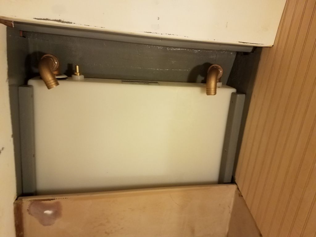
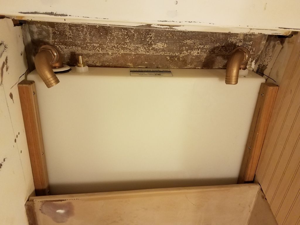
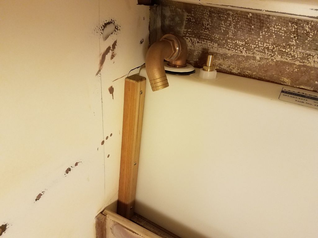
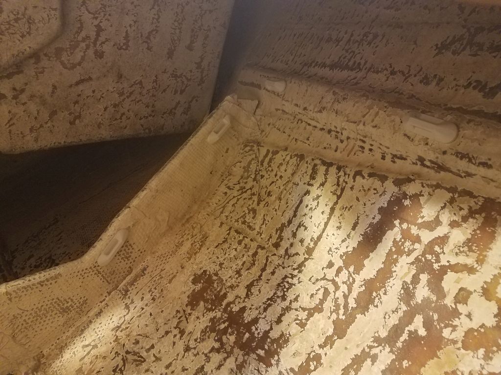
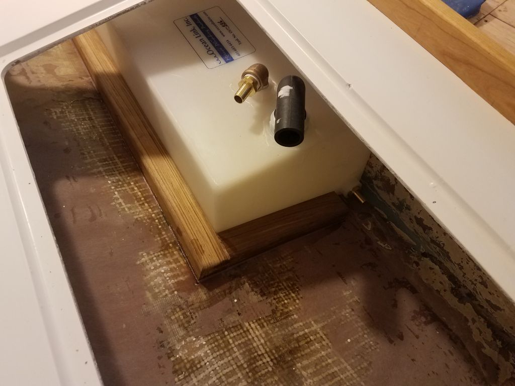
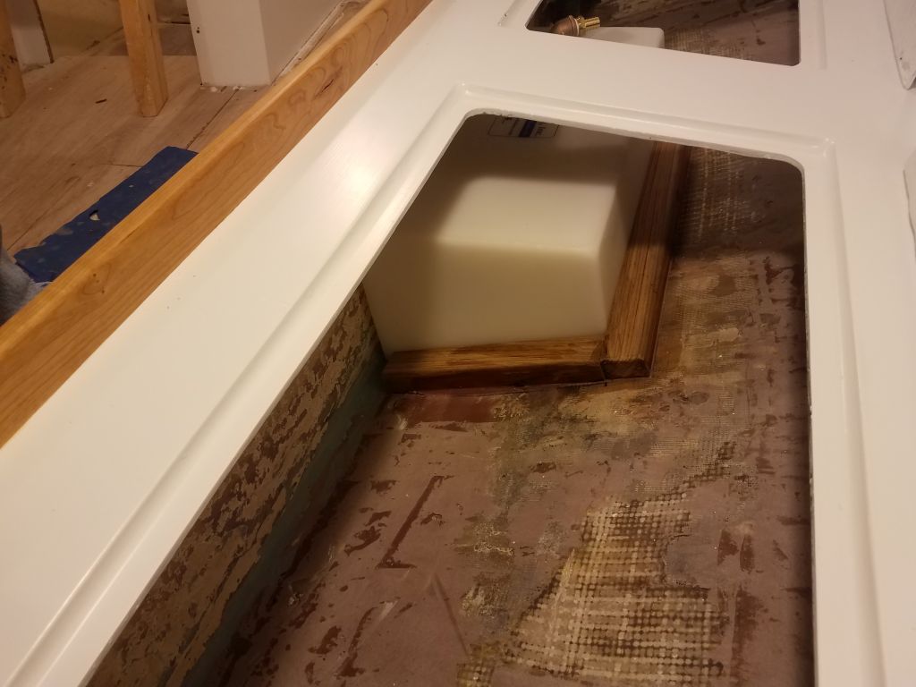
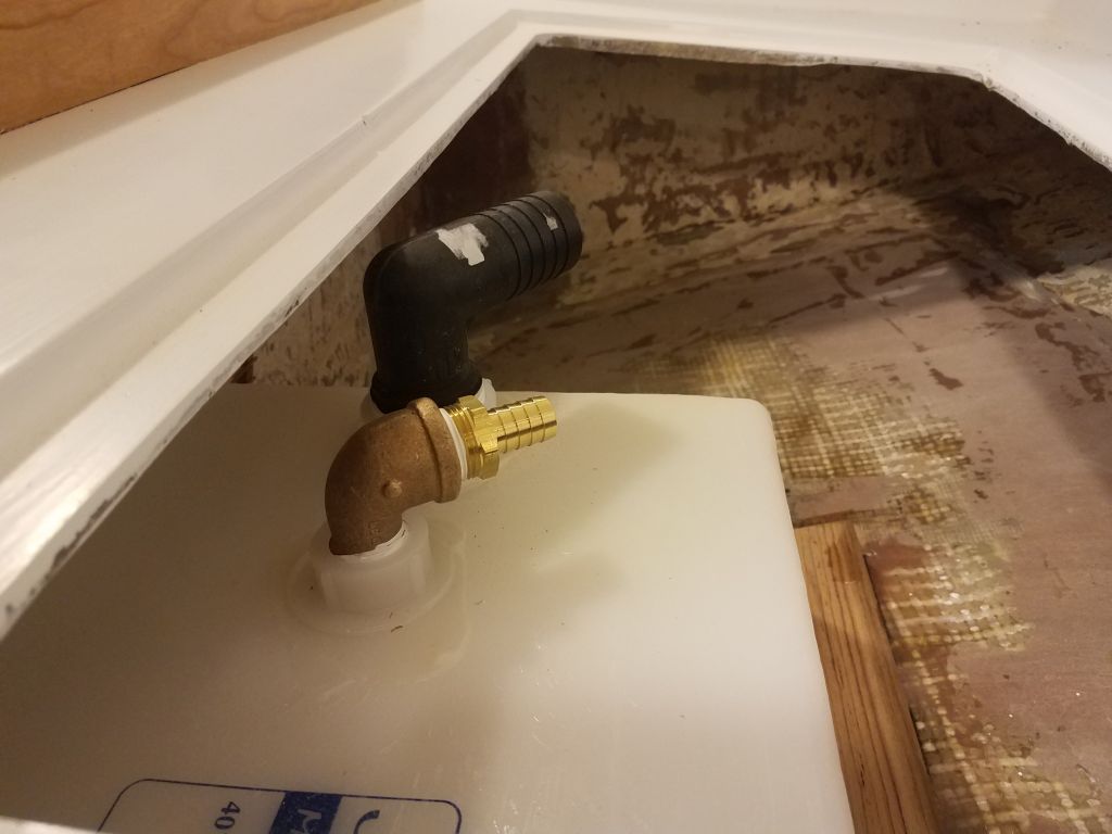
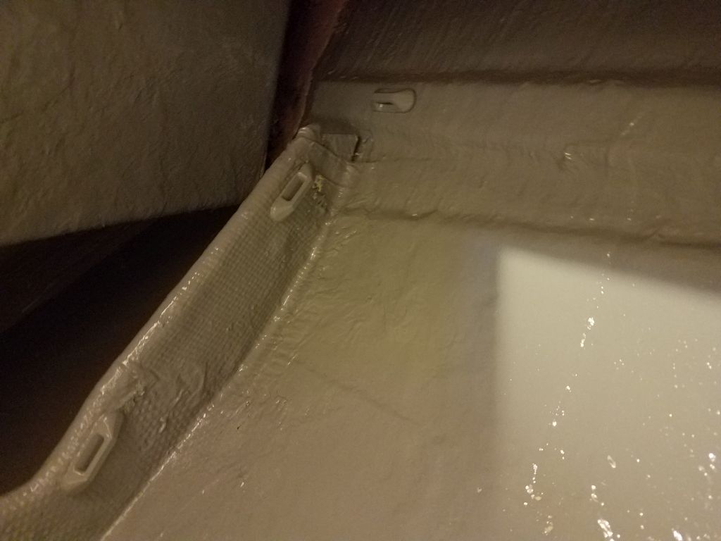
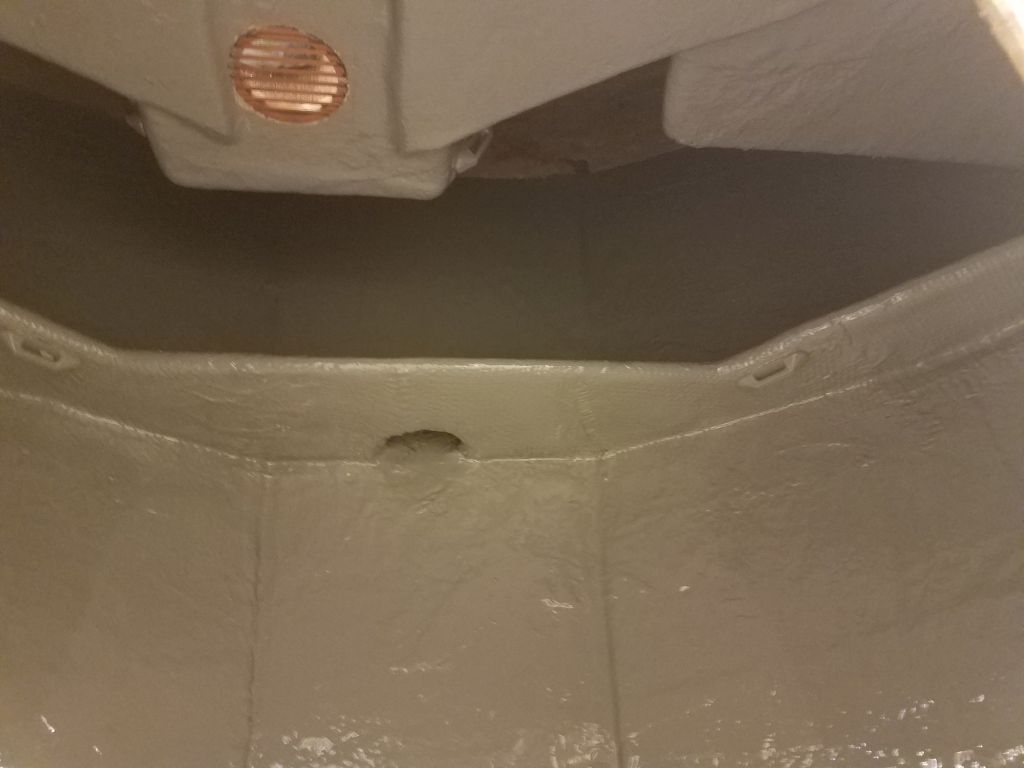
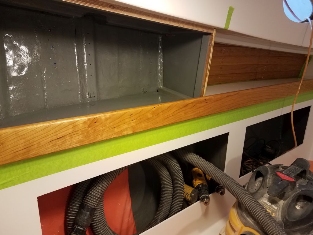
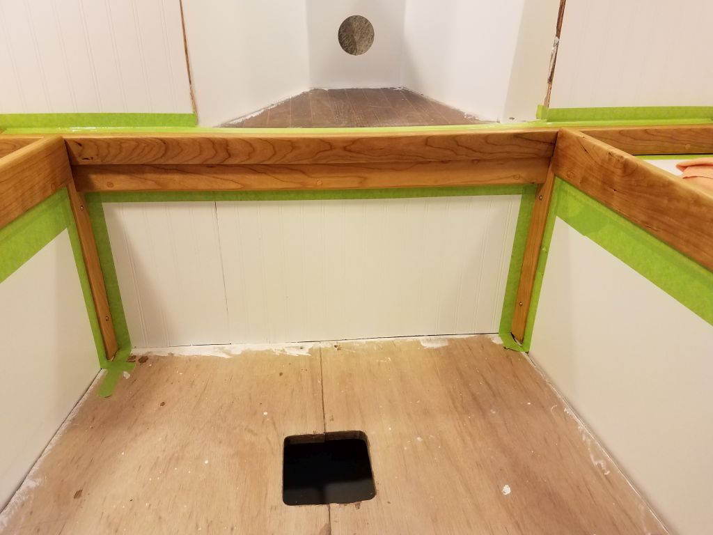
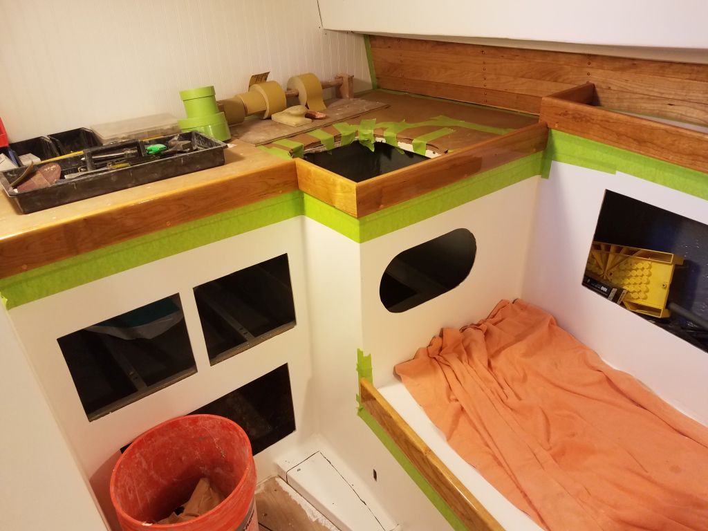
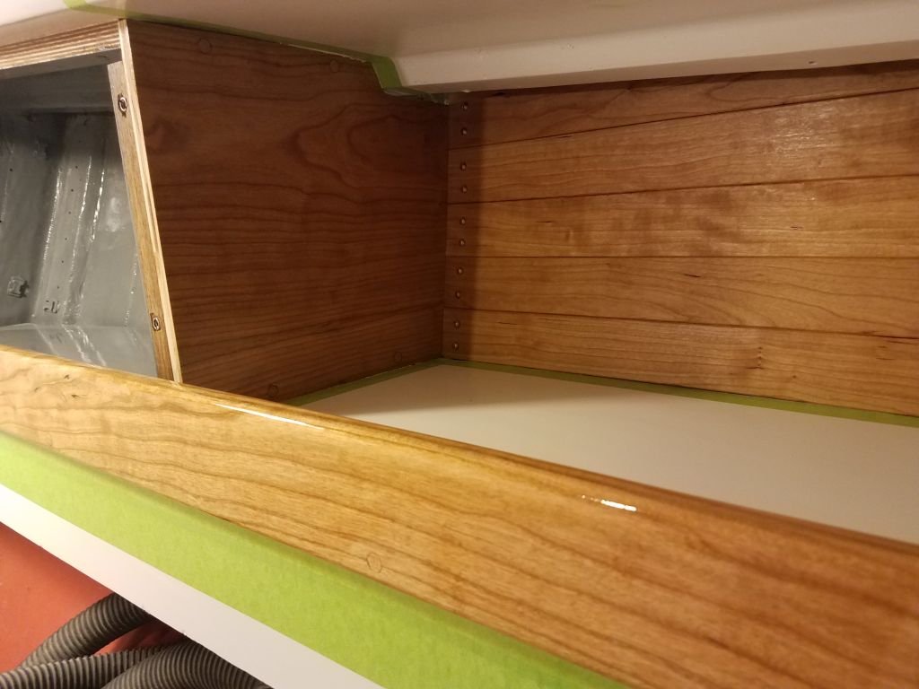
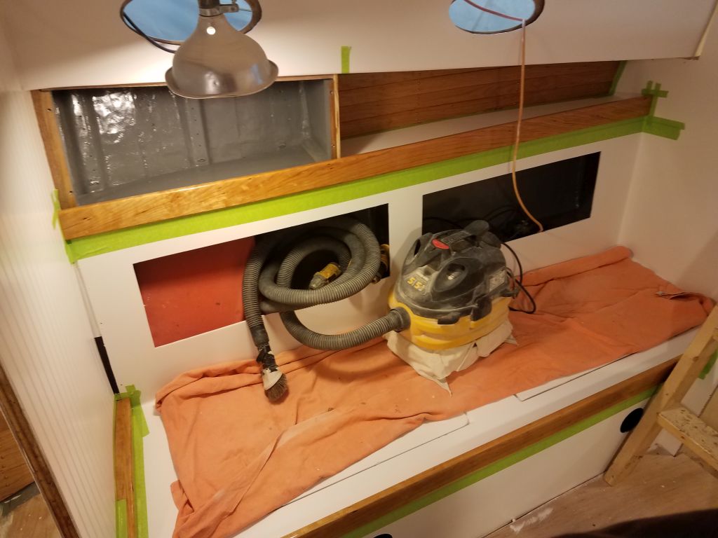
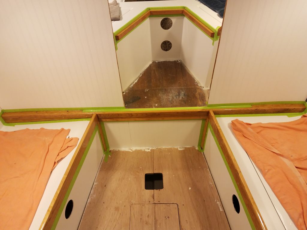
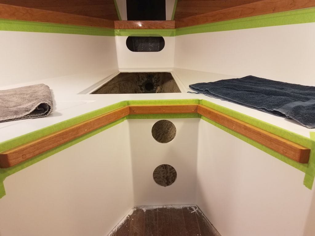
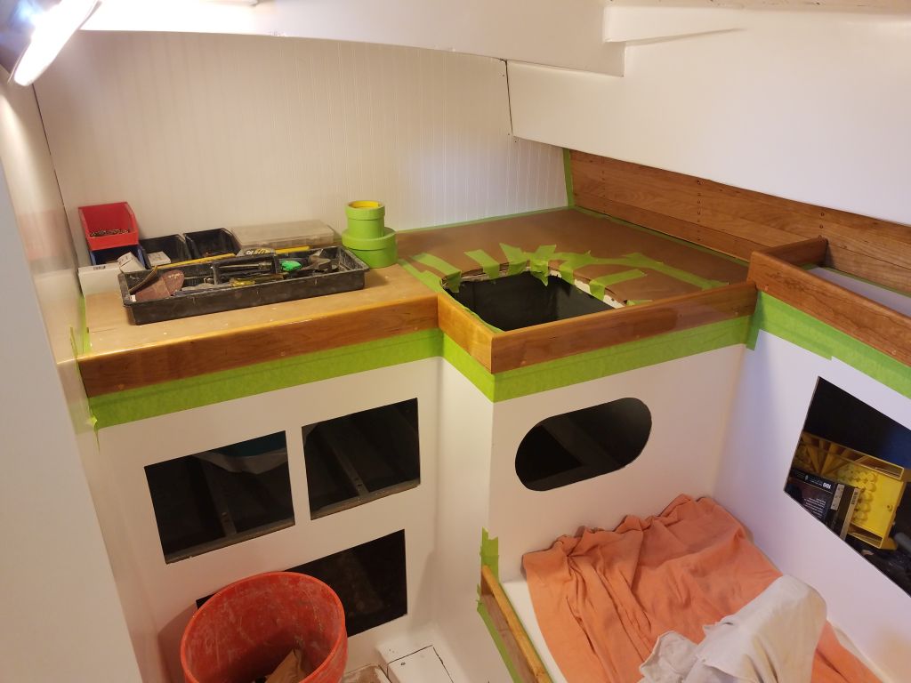
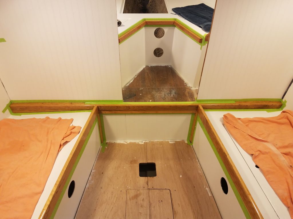
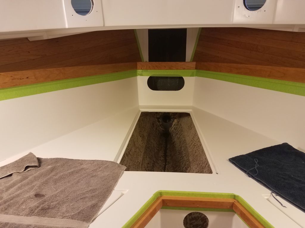
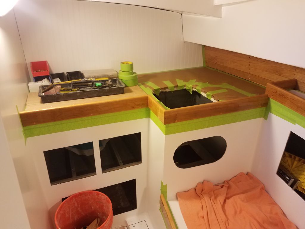
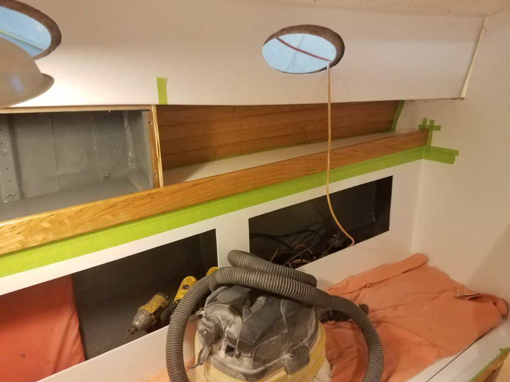
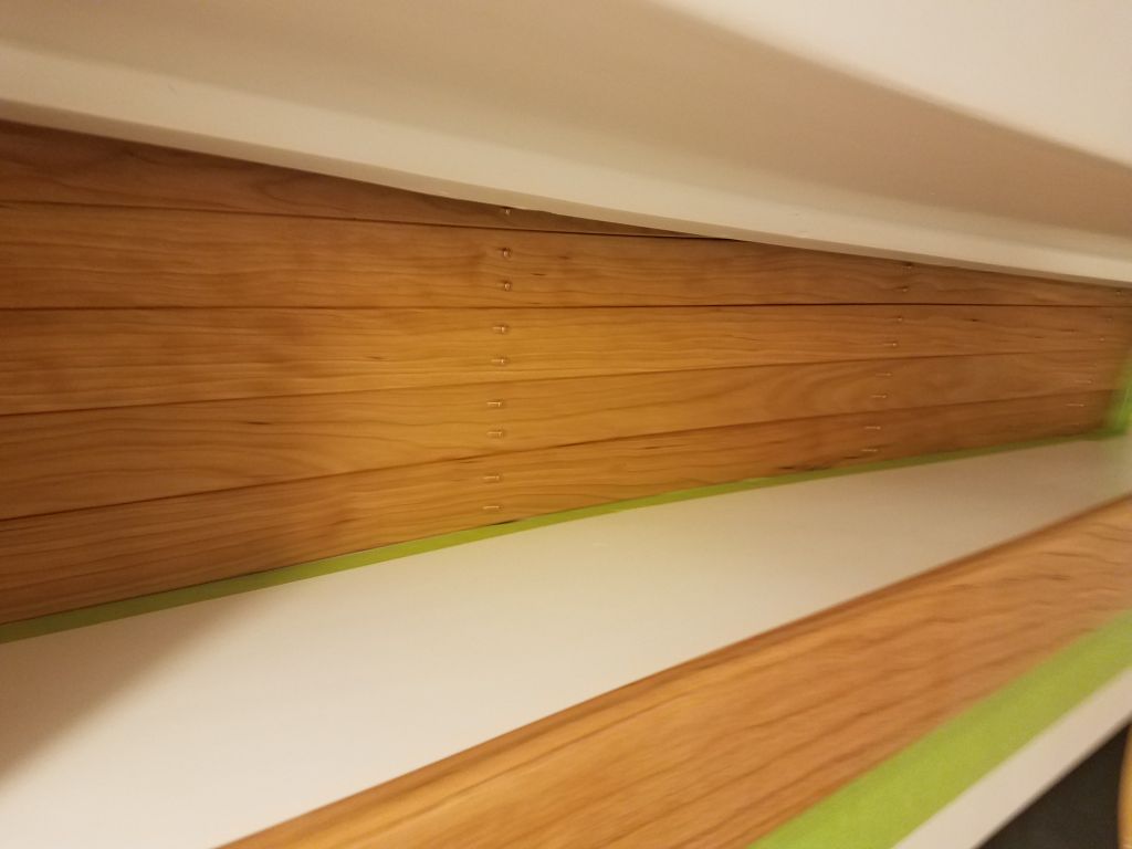
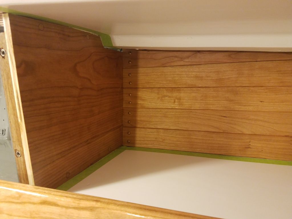
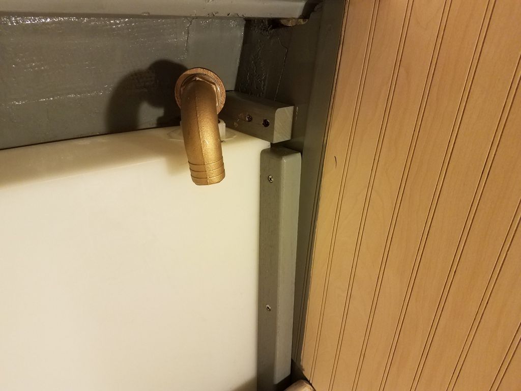
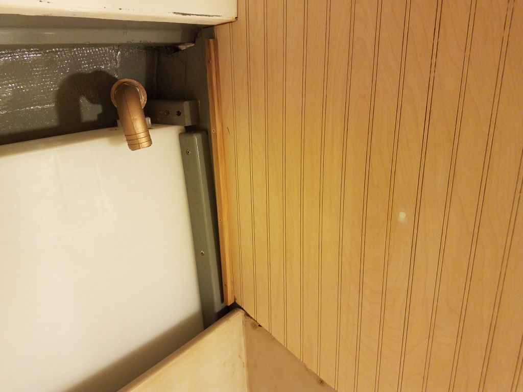
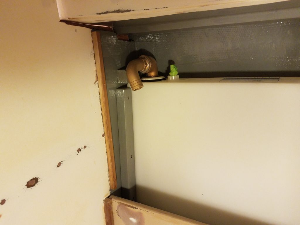
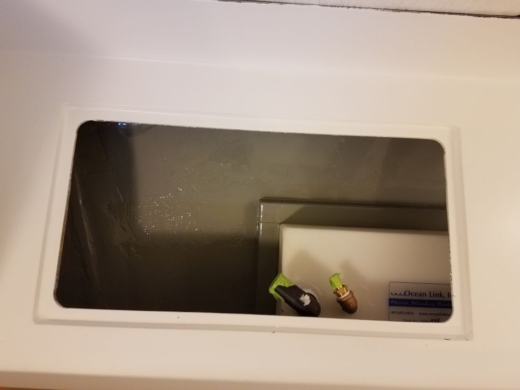
In the head, I began by installing the two top cleats to secure the holding tank, and then a pair of vertical cleats just inboard of the tank that would support the cover panel for the space later.

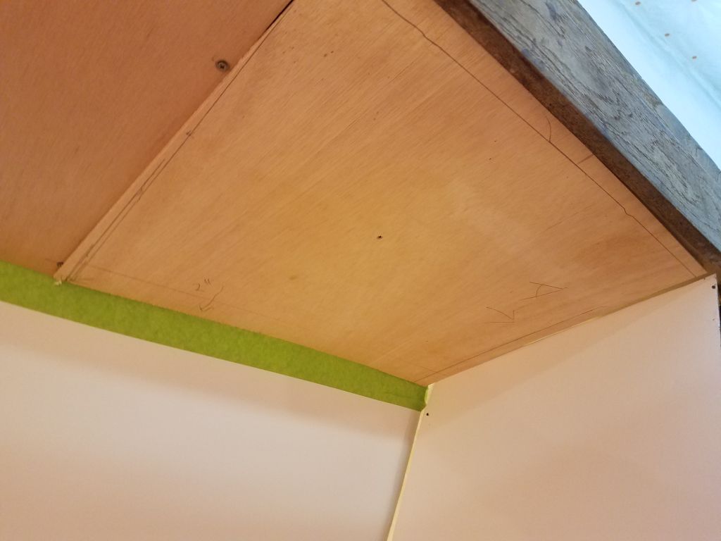
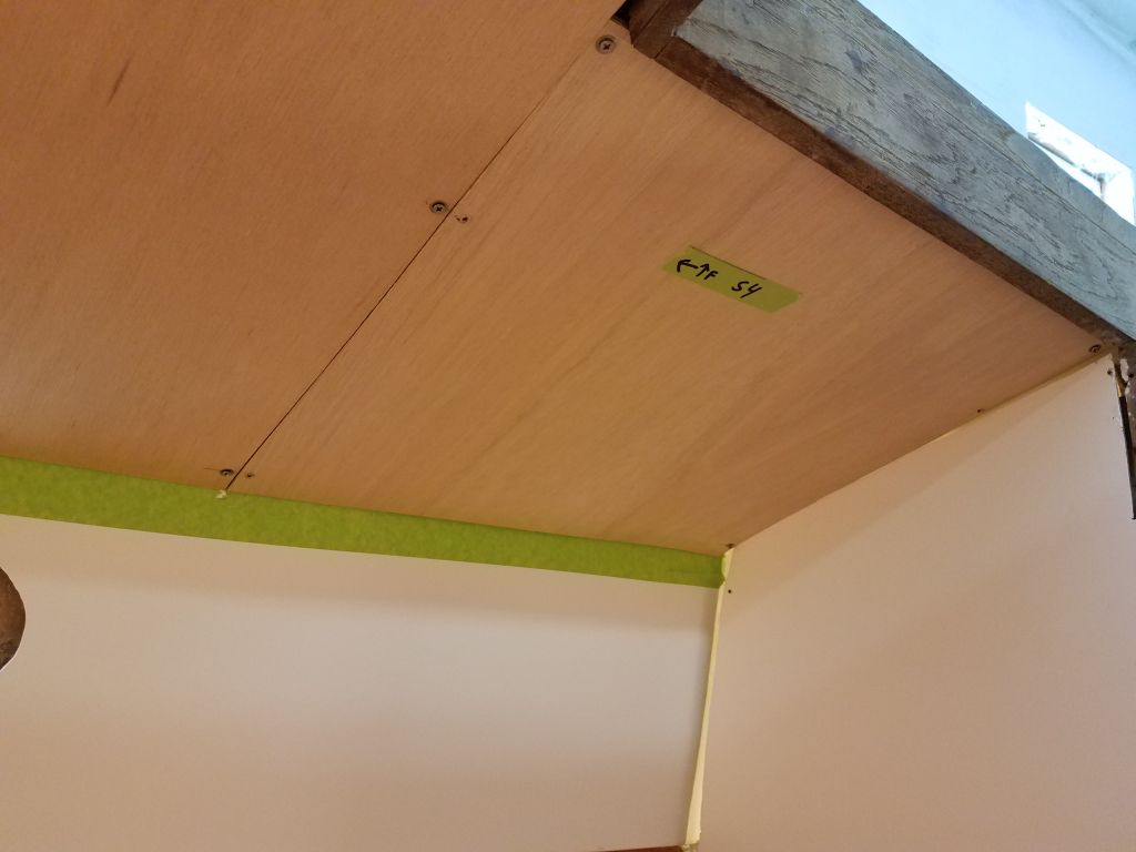
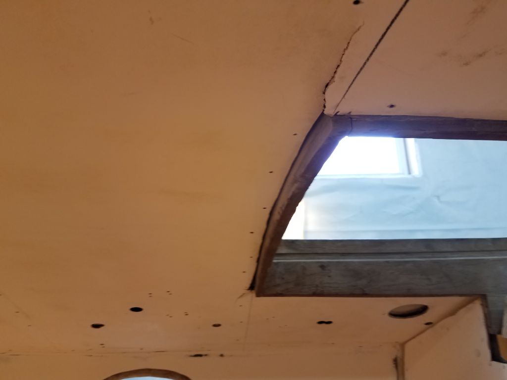
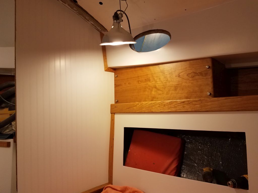
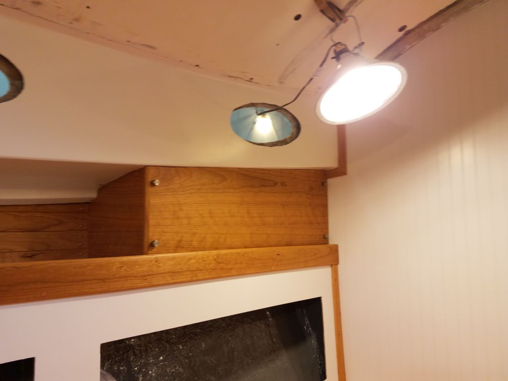
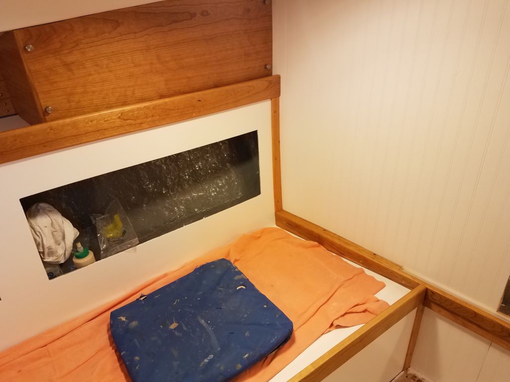
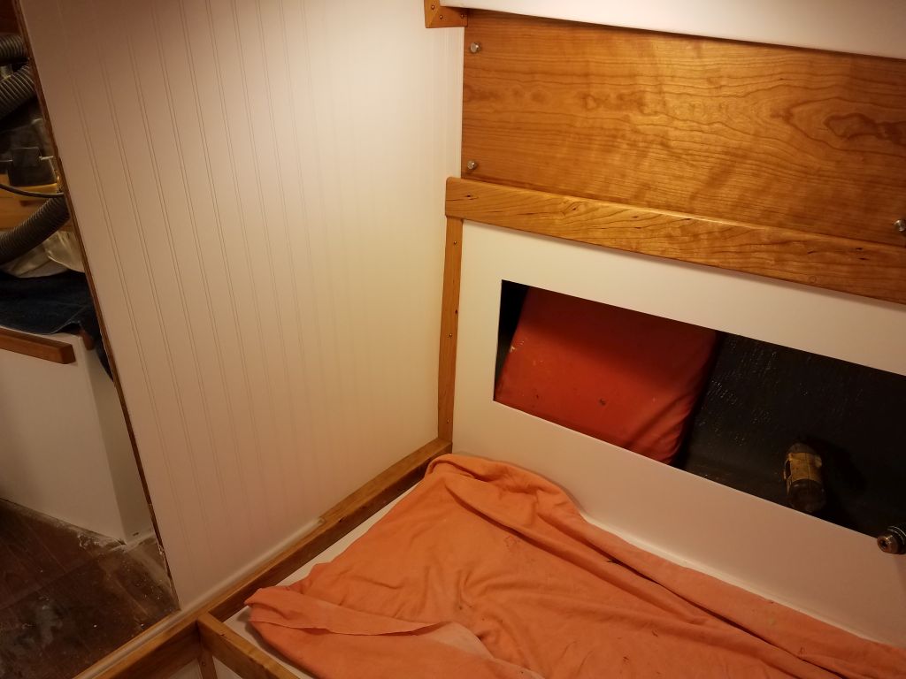
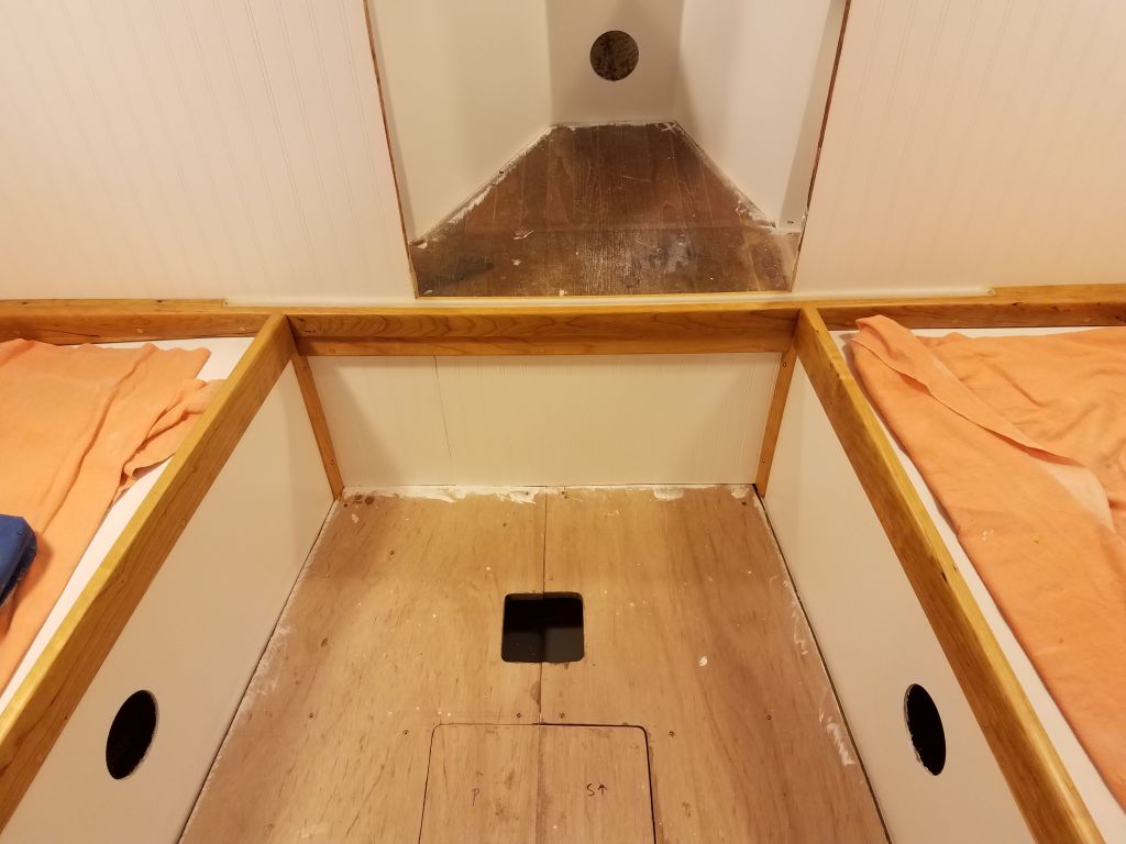
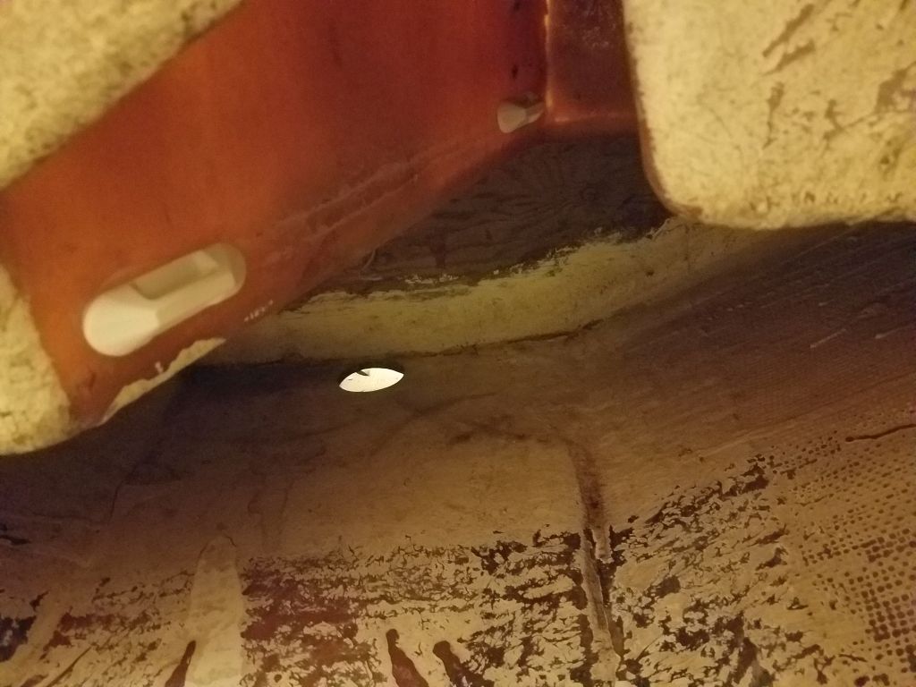
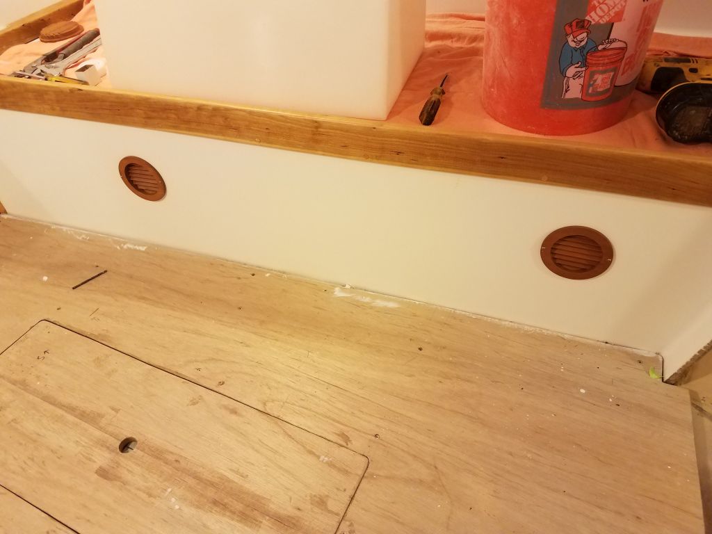
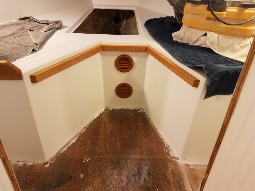
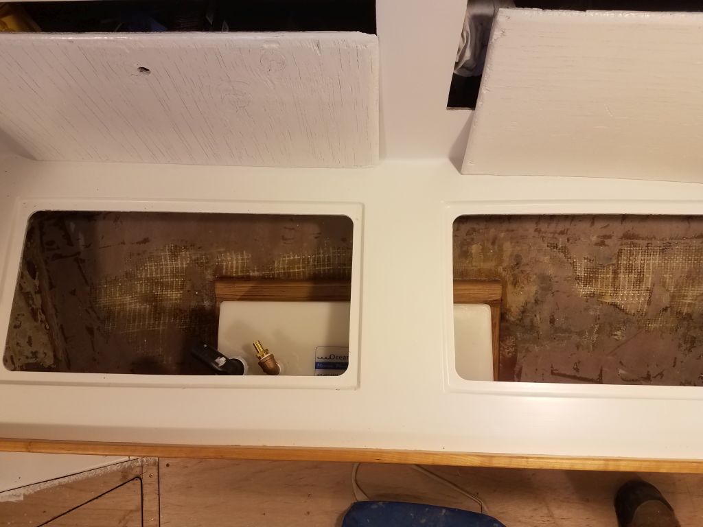
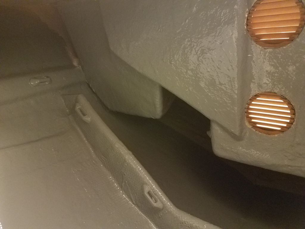
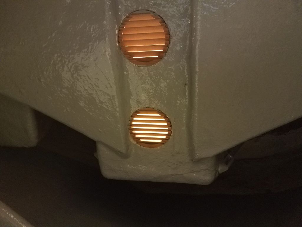
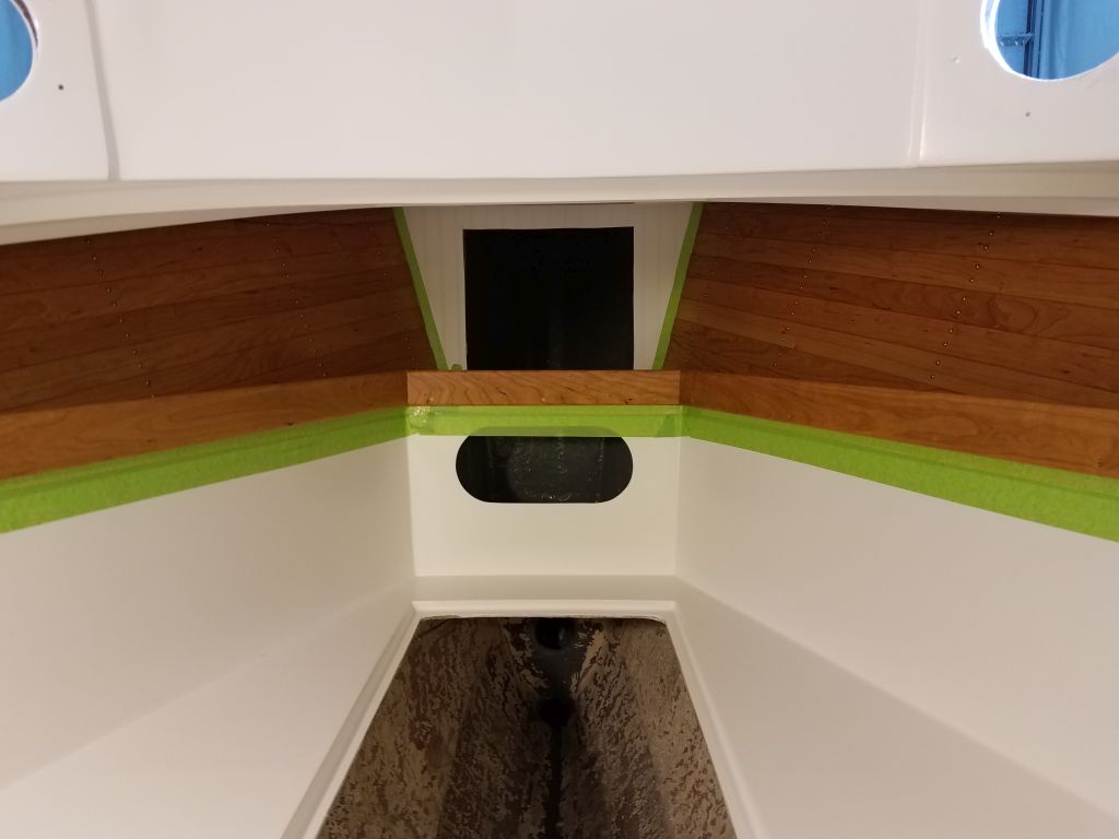
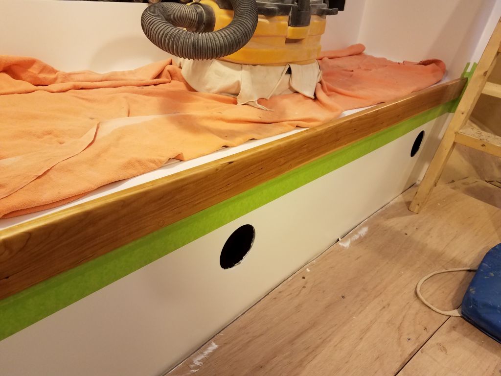
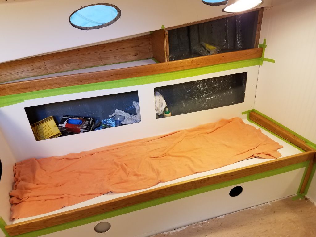
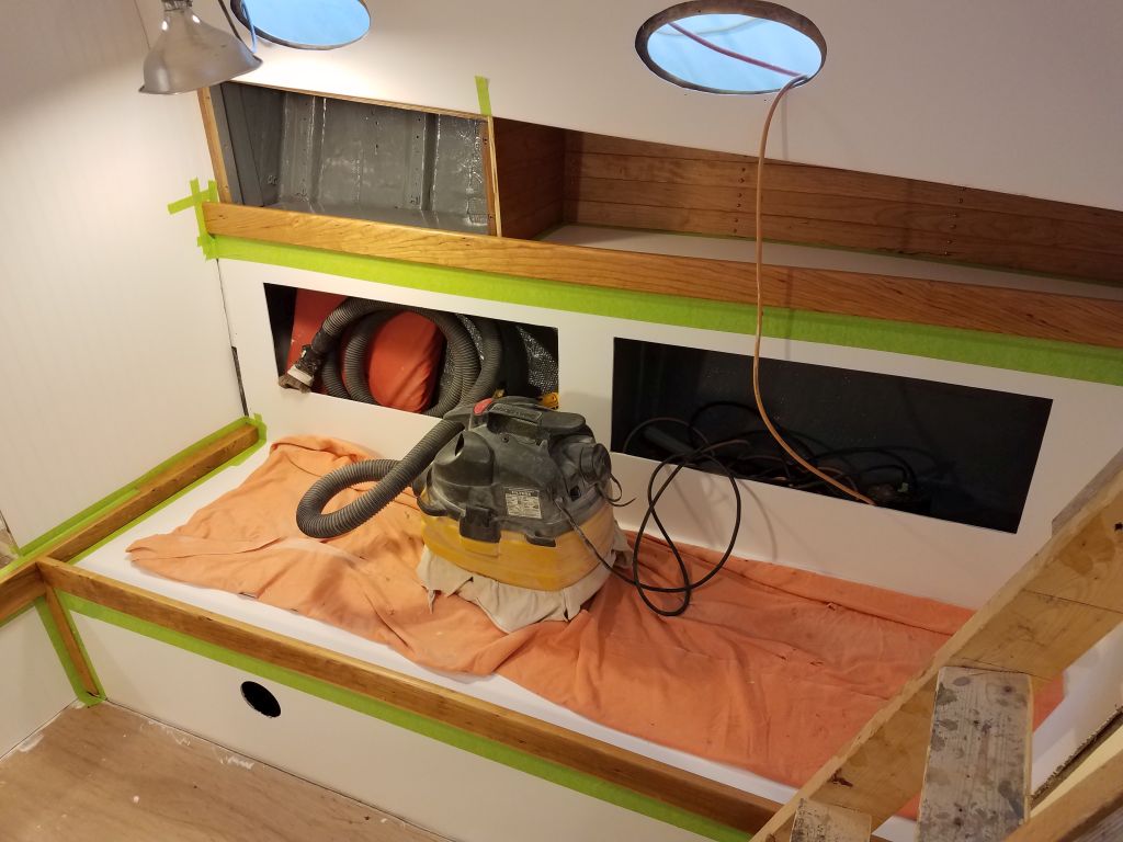
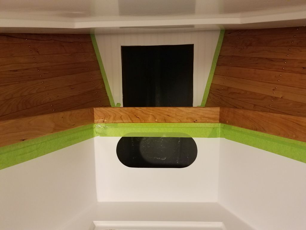
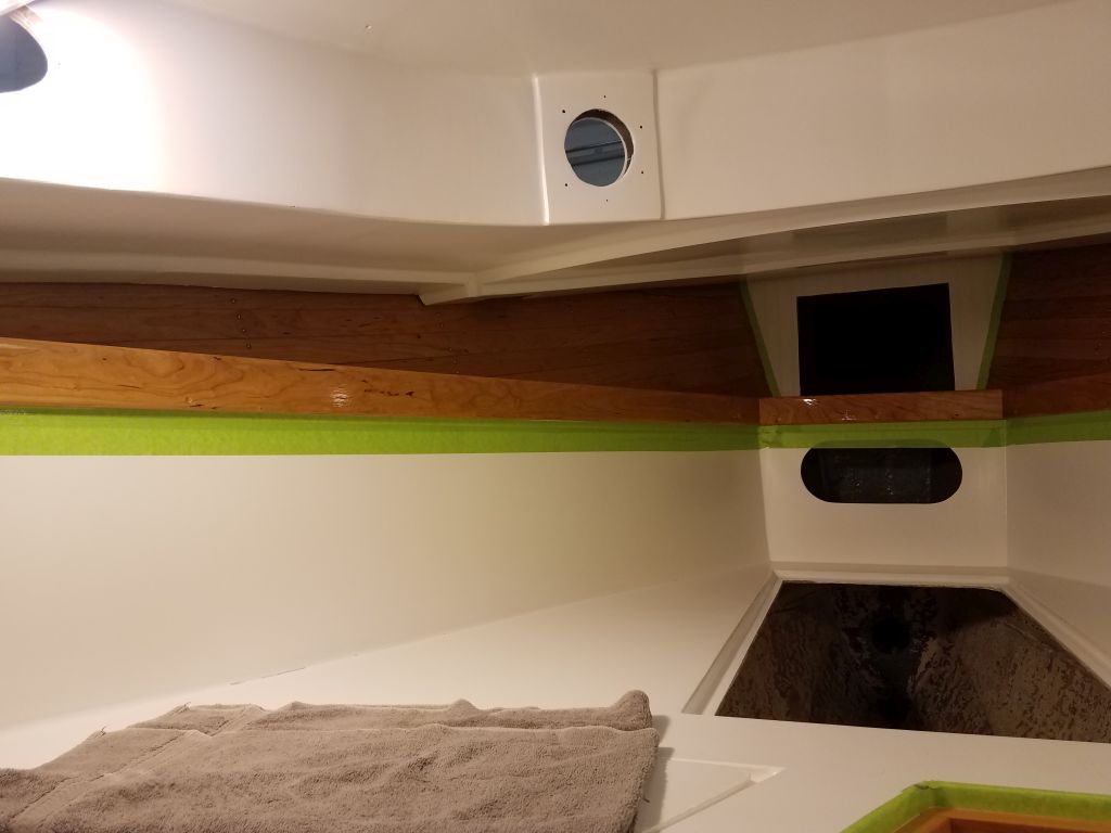
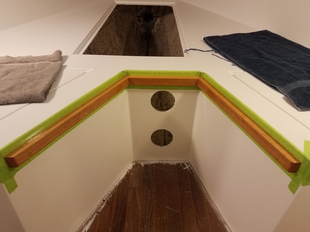
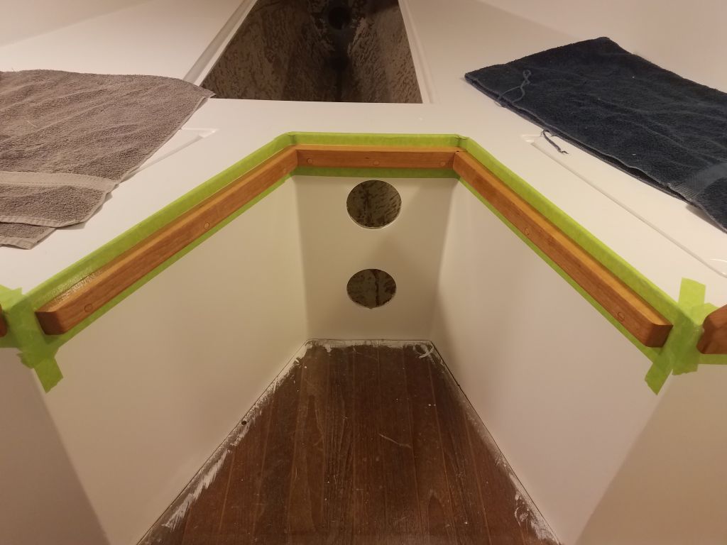
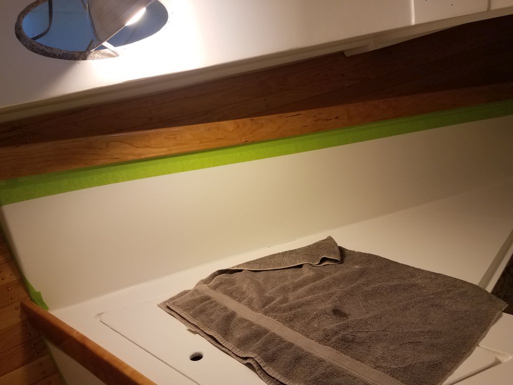
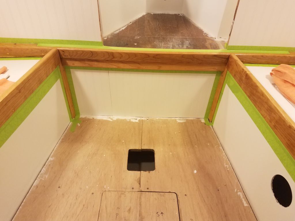
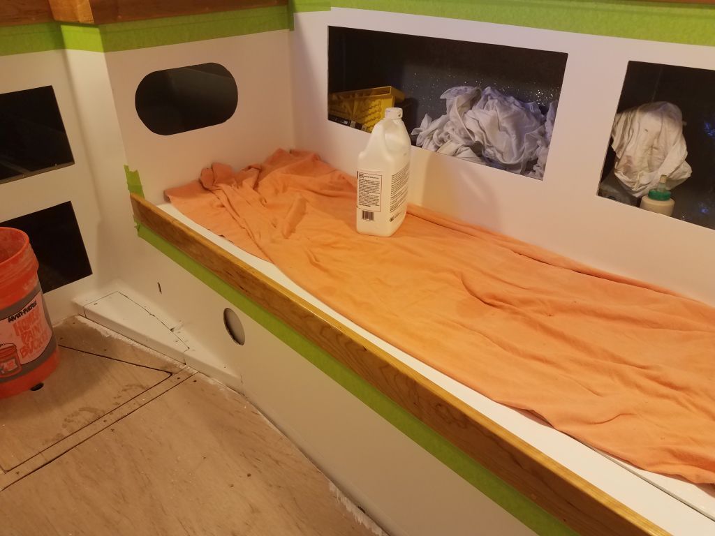
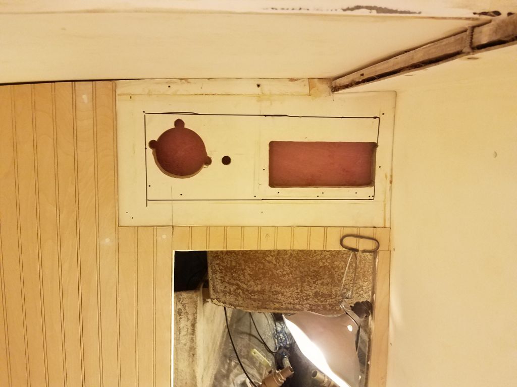
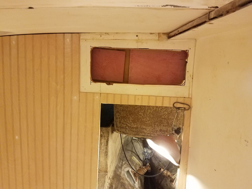
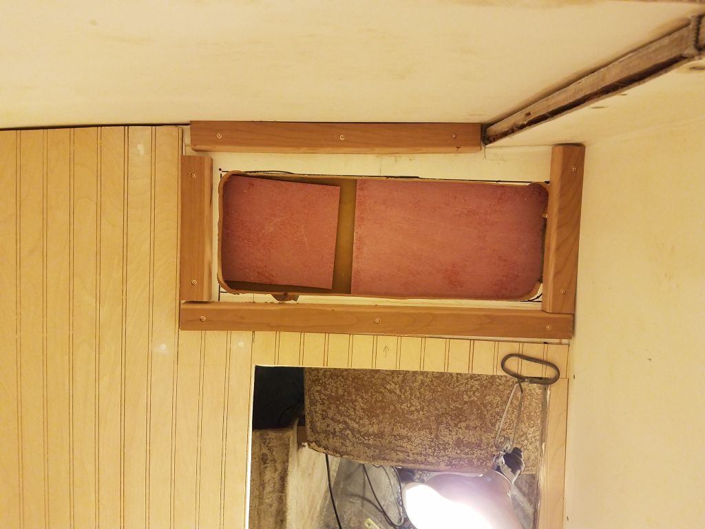
To provide future access for instrumentation in the cockpit, I enlarged the existing openings through the aft bulkhead in the head, in the space I’d left unpaneled for this purpose.  The larger hole would give better access to the actual back side of the cockpit bulkhead for possible instrumentation installations later.  Afterwards, I cut and installed hardwood cleats around the space to support the cover panel that I’d build later.

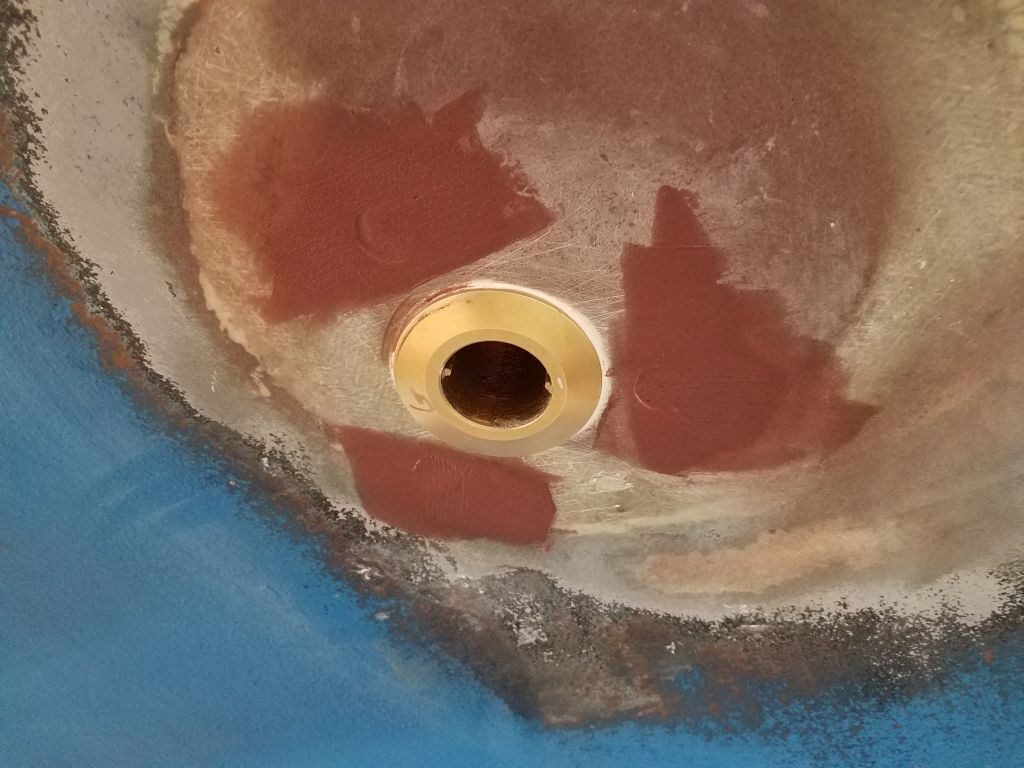
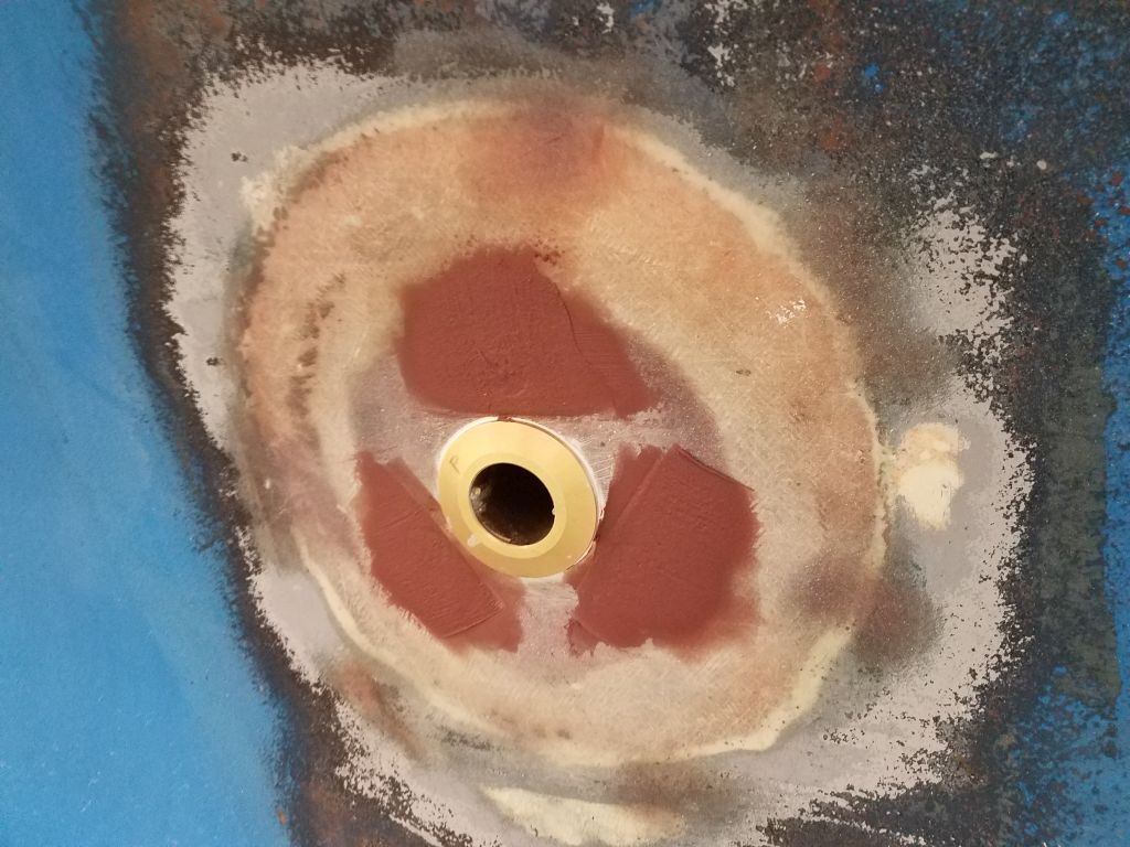
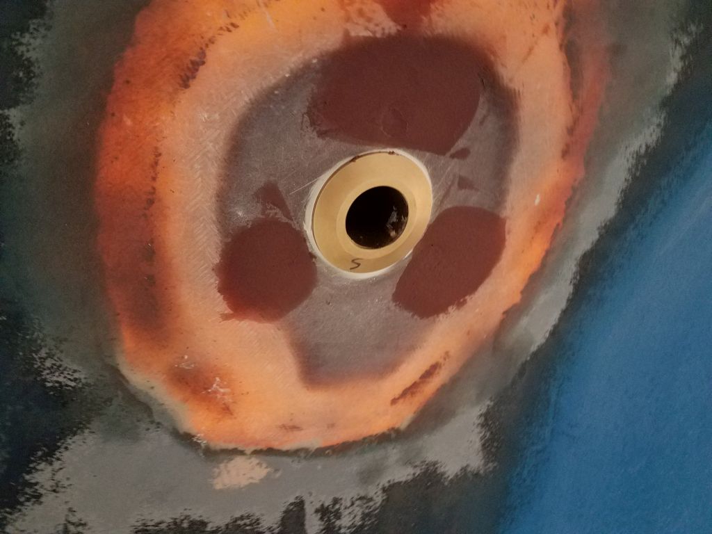
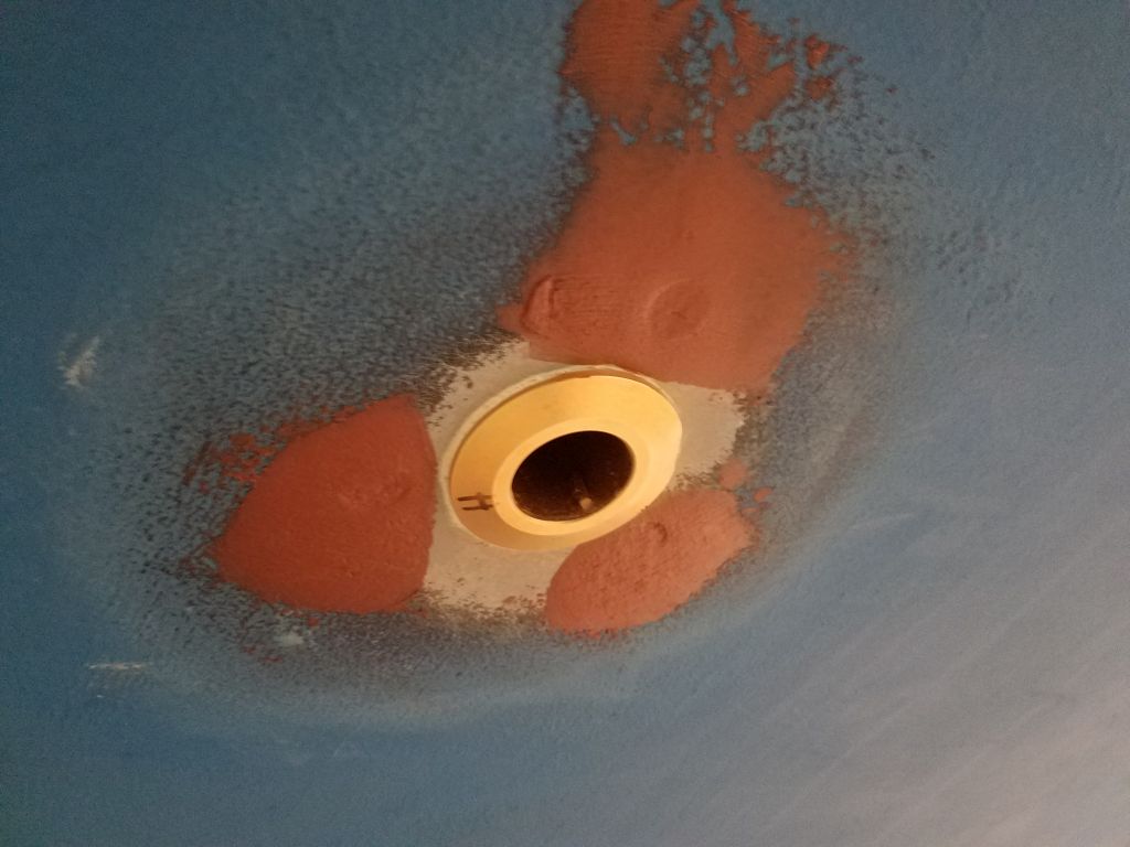
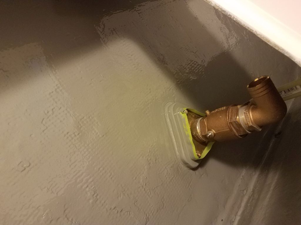
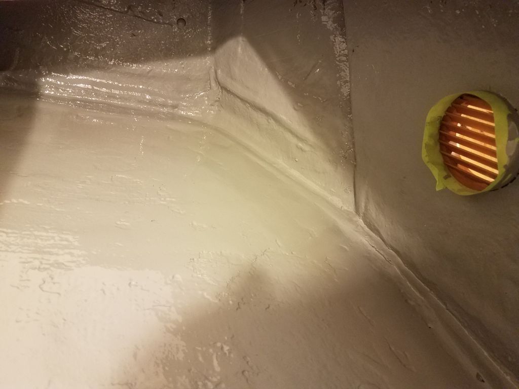
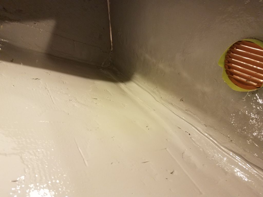
The heads of the bolts securing the through hull valves were recessed slightly in the hull, and now I mixed up some epoxy fairing compound and filled these holes so I could sand them flush later.

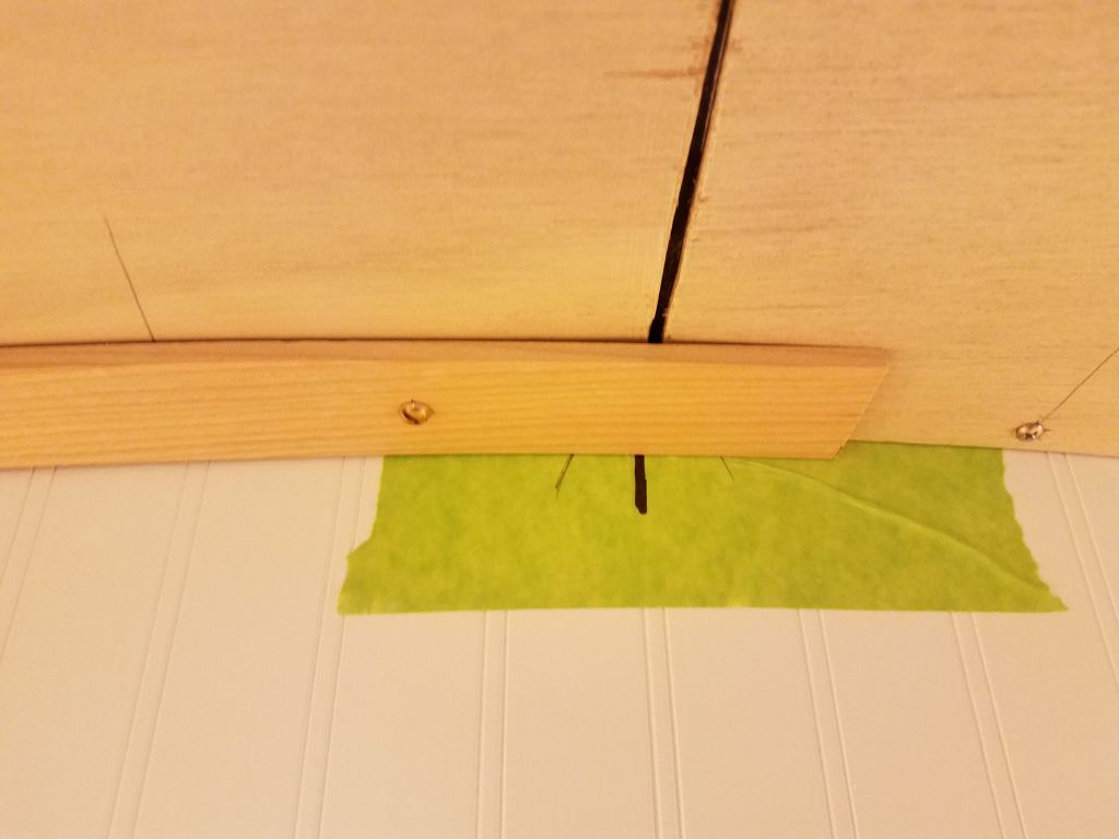
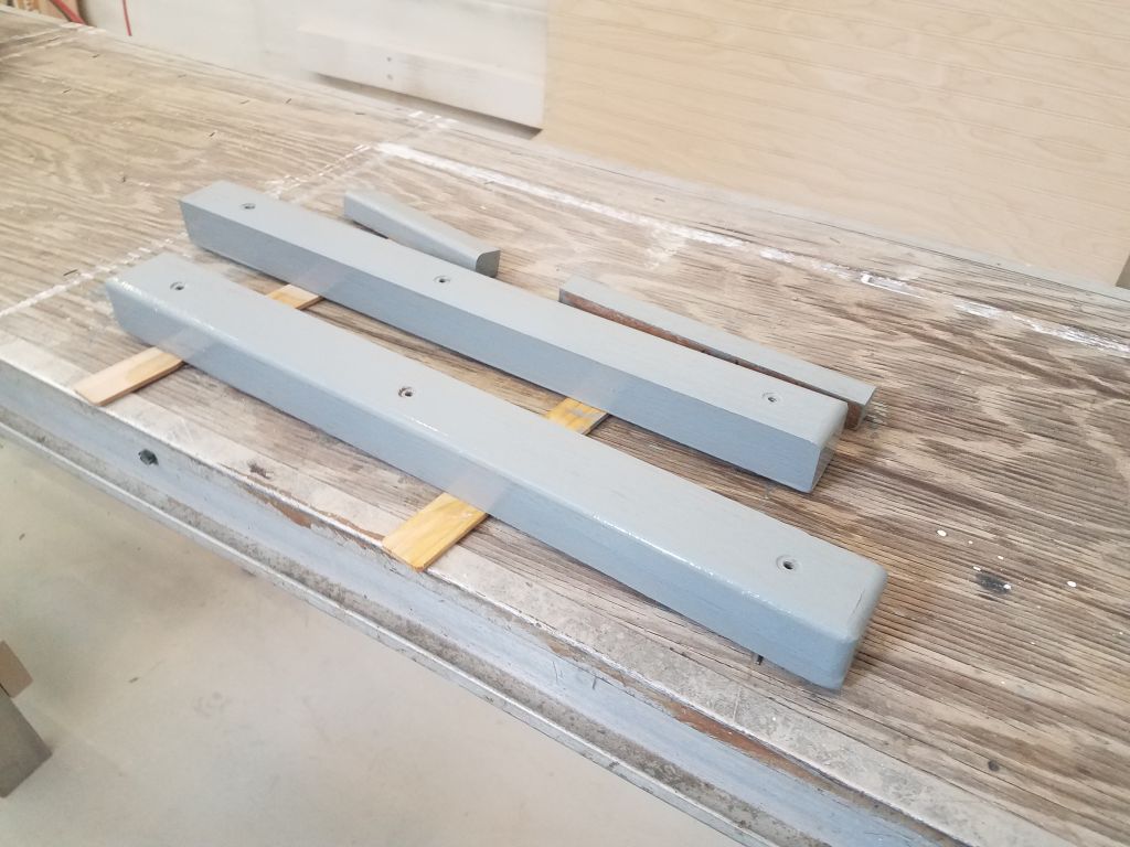
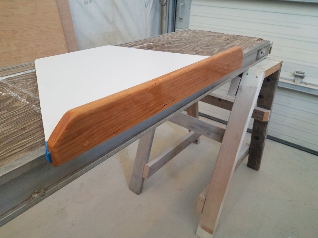
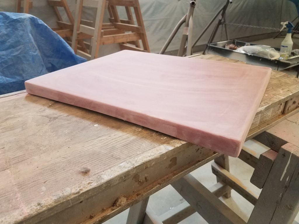
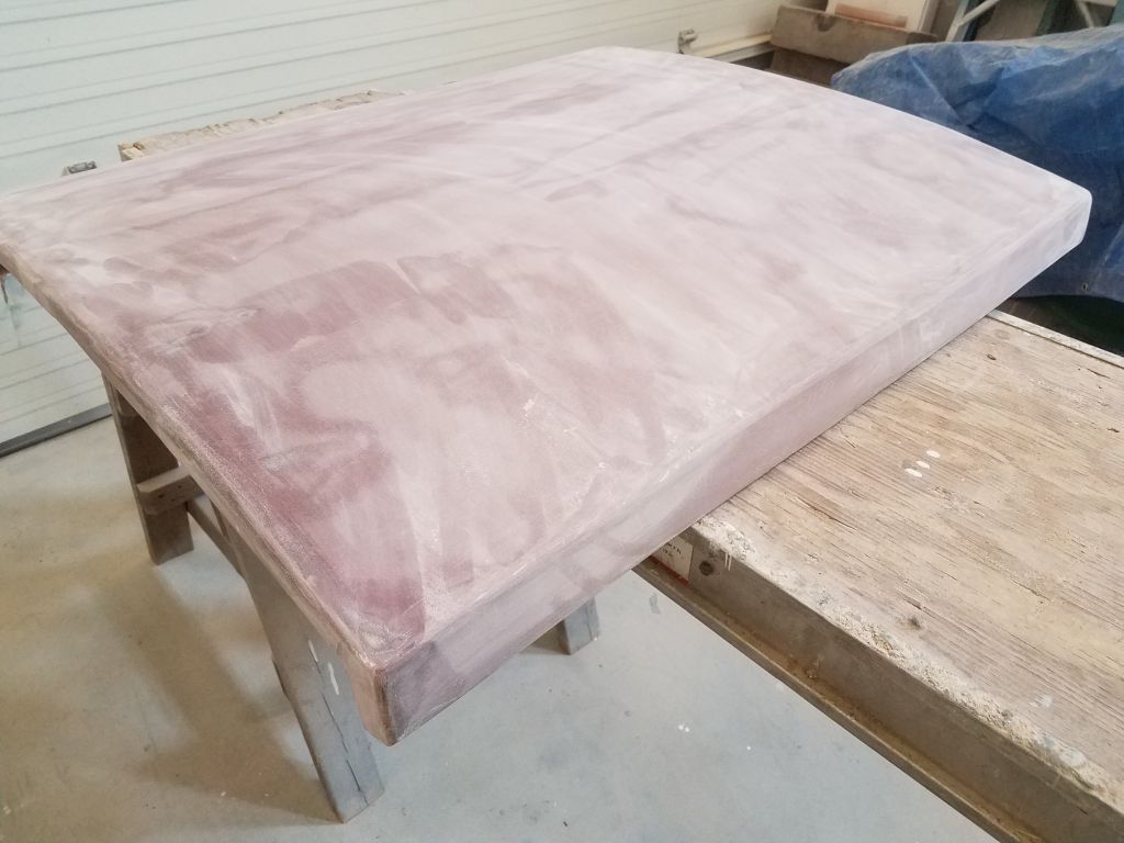
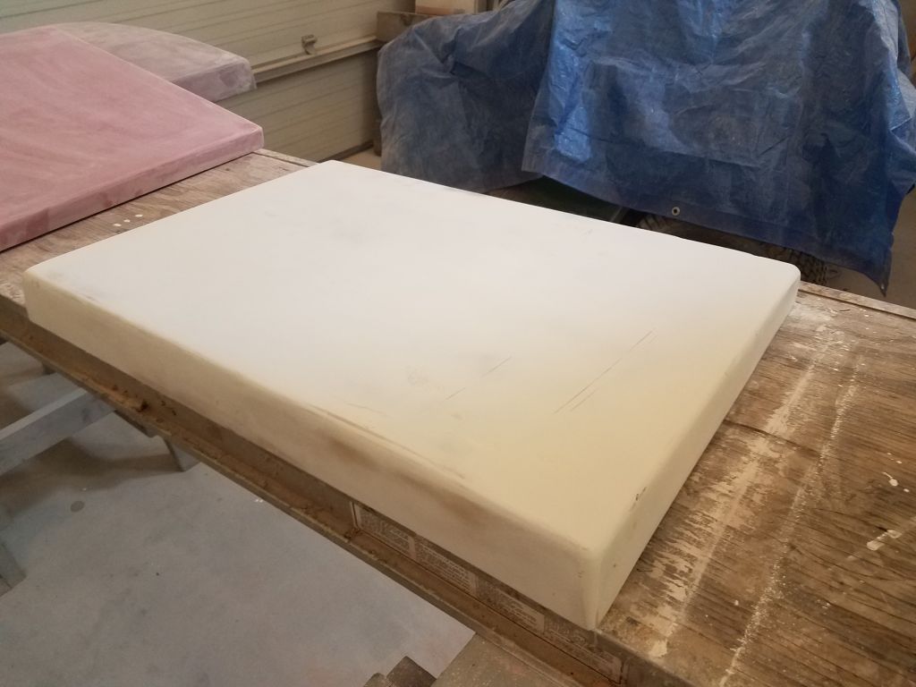
I scribed the new lazarette hatch to the curvature of the aft deck, then shaped the hatch to the lines before sanding the whole thing smooth to get it ready for primer and paint.

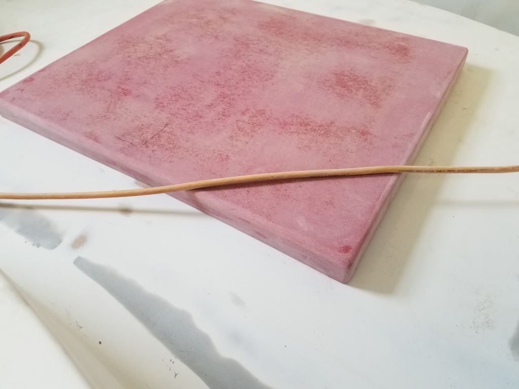
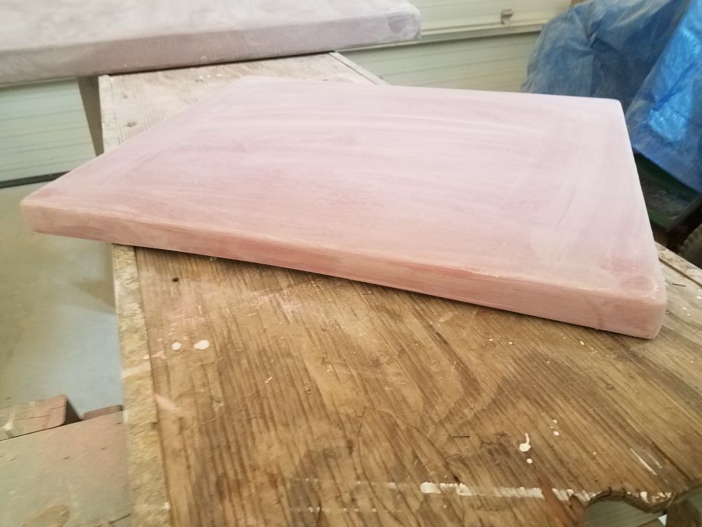
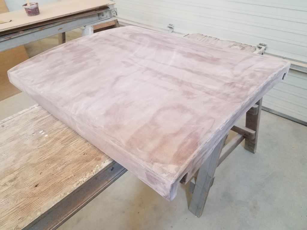
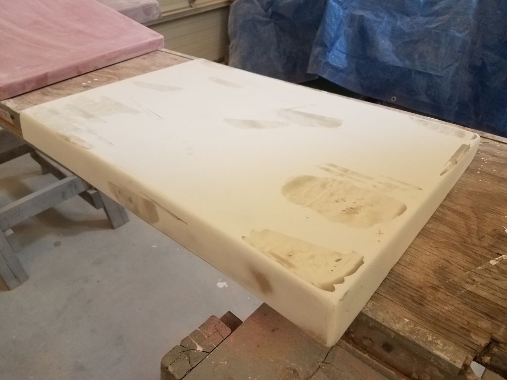
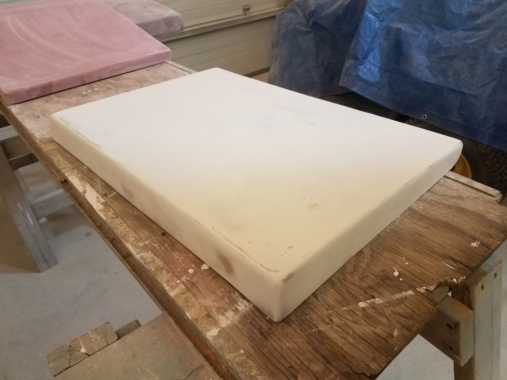
Some days before, I’d applied a final coat of fairing compound to portions of the companionway sliding hatch, and now I sanded the filler smooth, and sanded the whole hatch smooth and clean to prepare it for primer and paint.

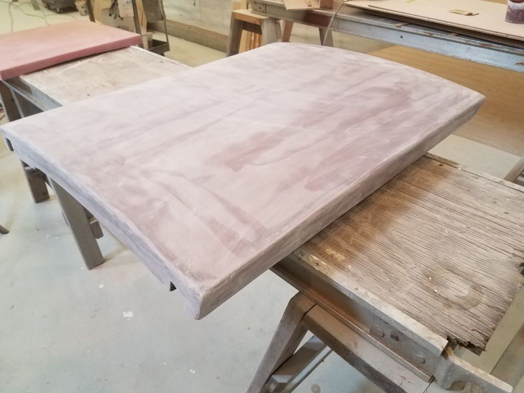
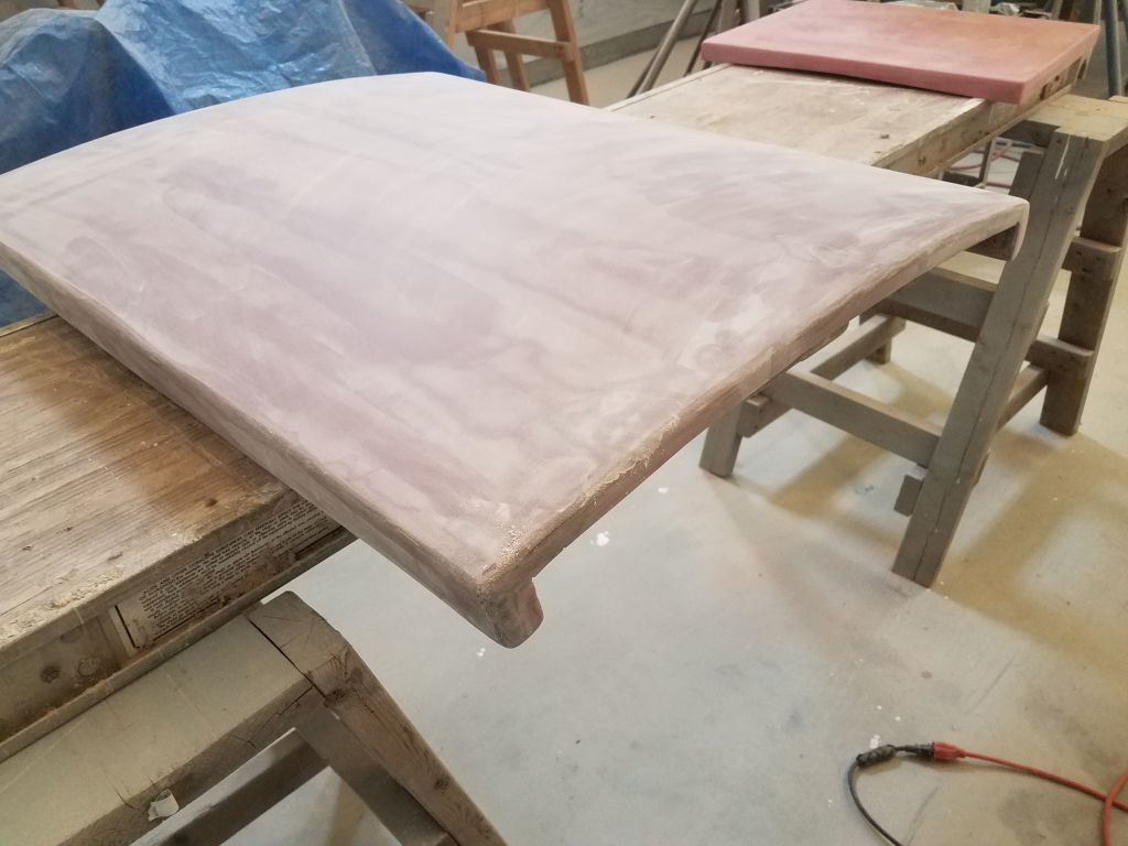
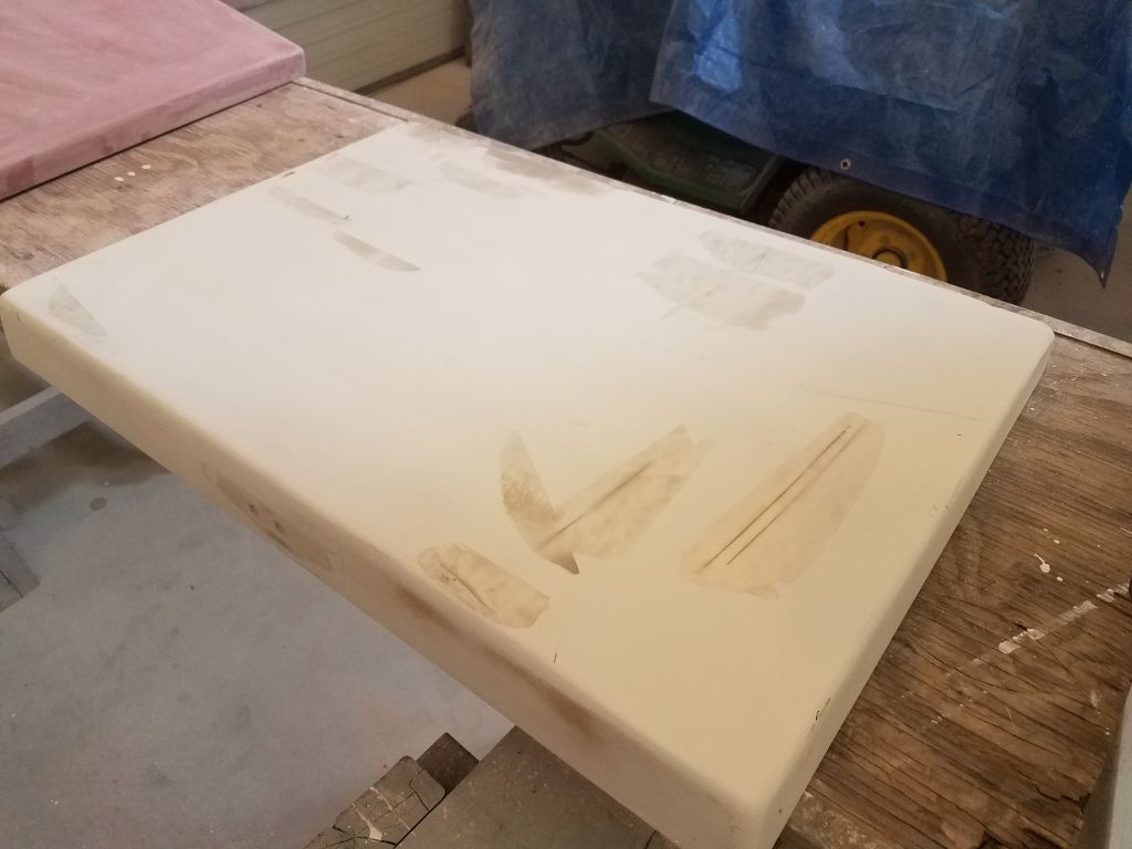
Sticking with the hatch theme, I uncovered the two cockpit locker hatches, to which I’d long ago applied some fine filler to the minor pinholes and such after high-build primer, and sanded these smooth as needed.

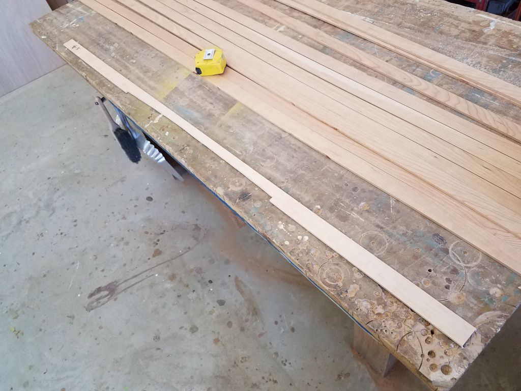
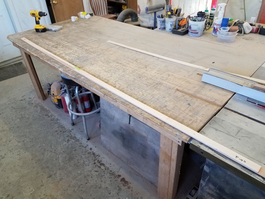
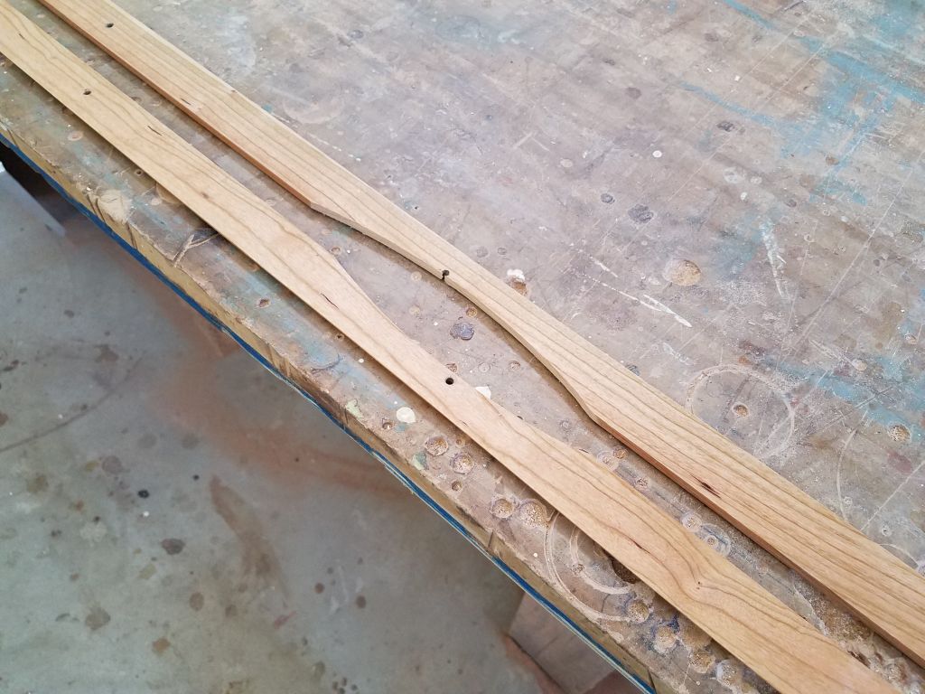
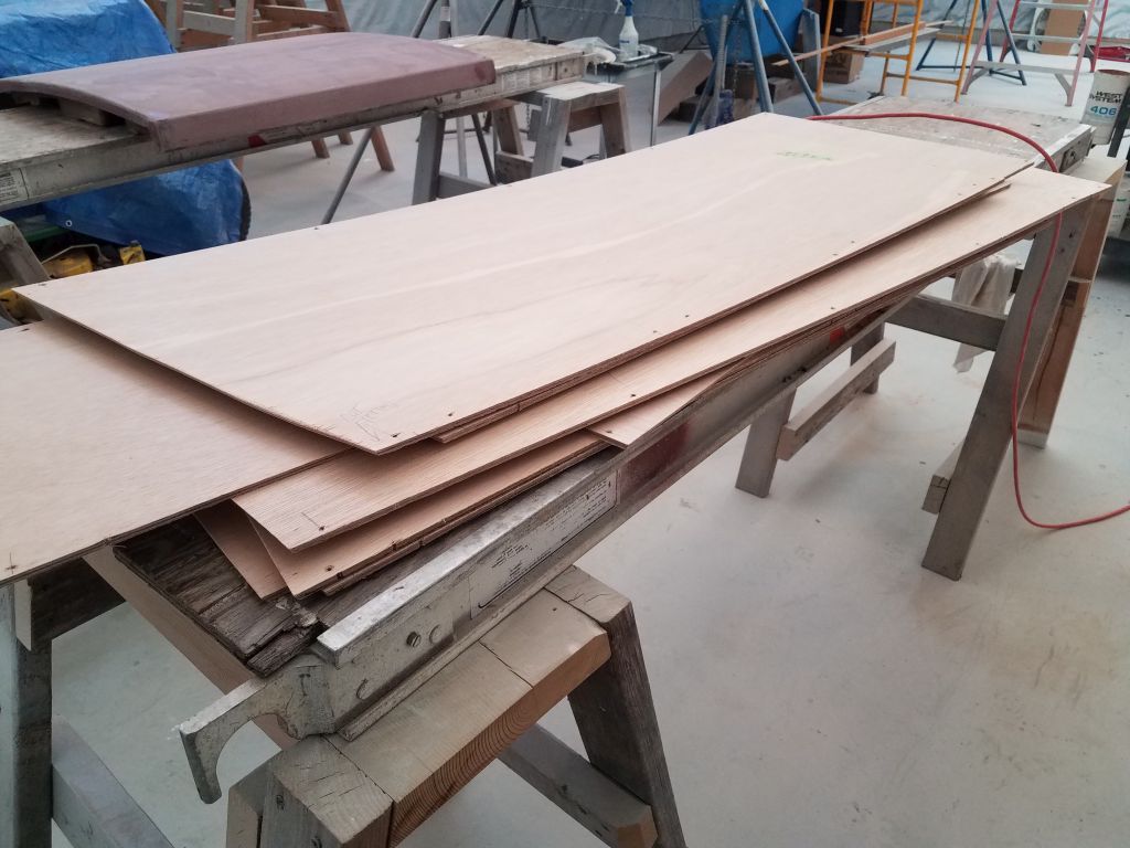
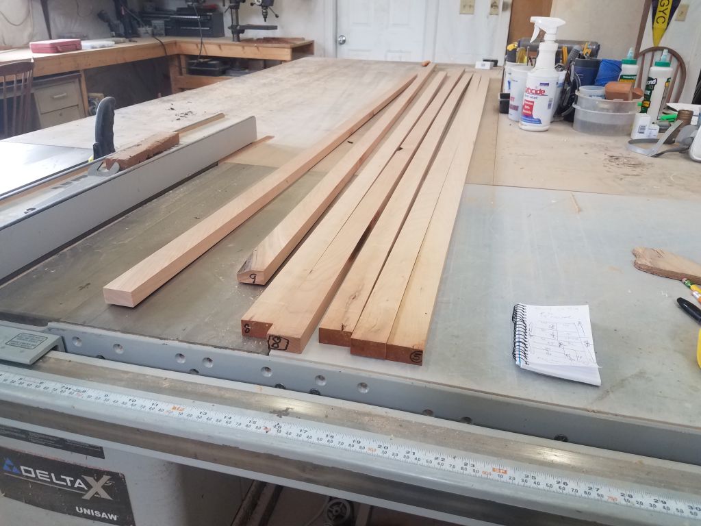
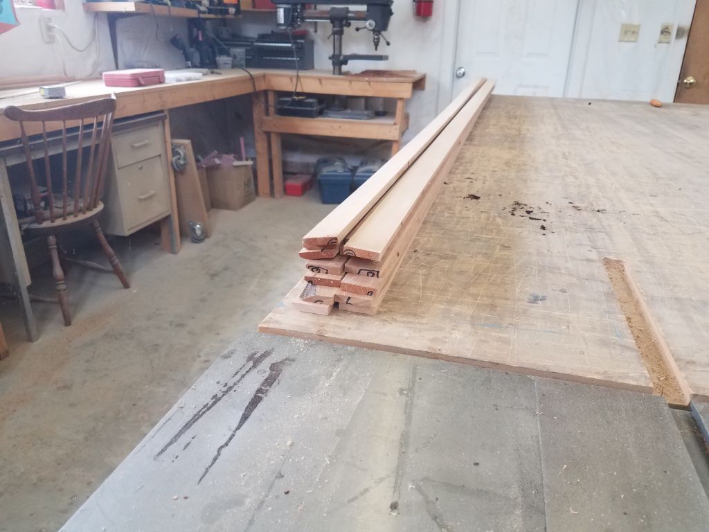
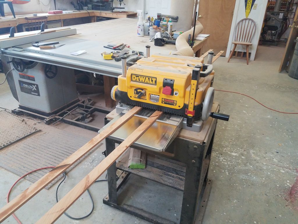
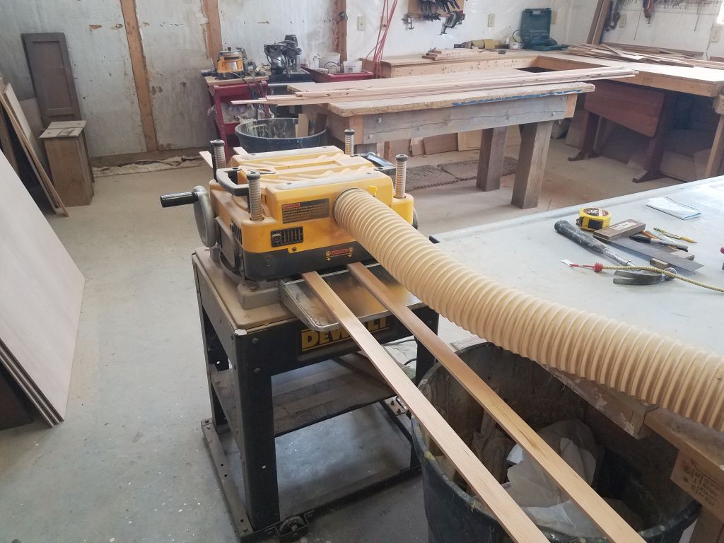
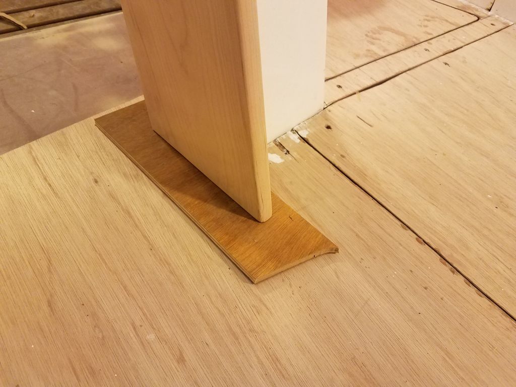
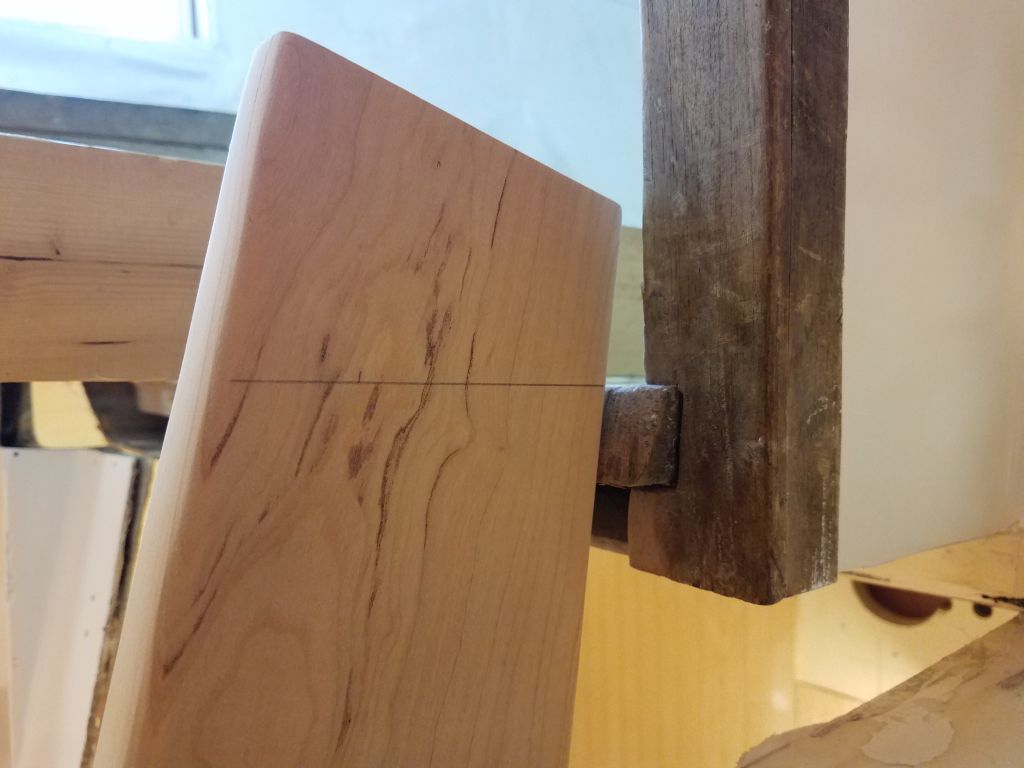
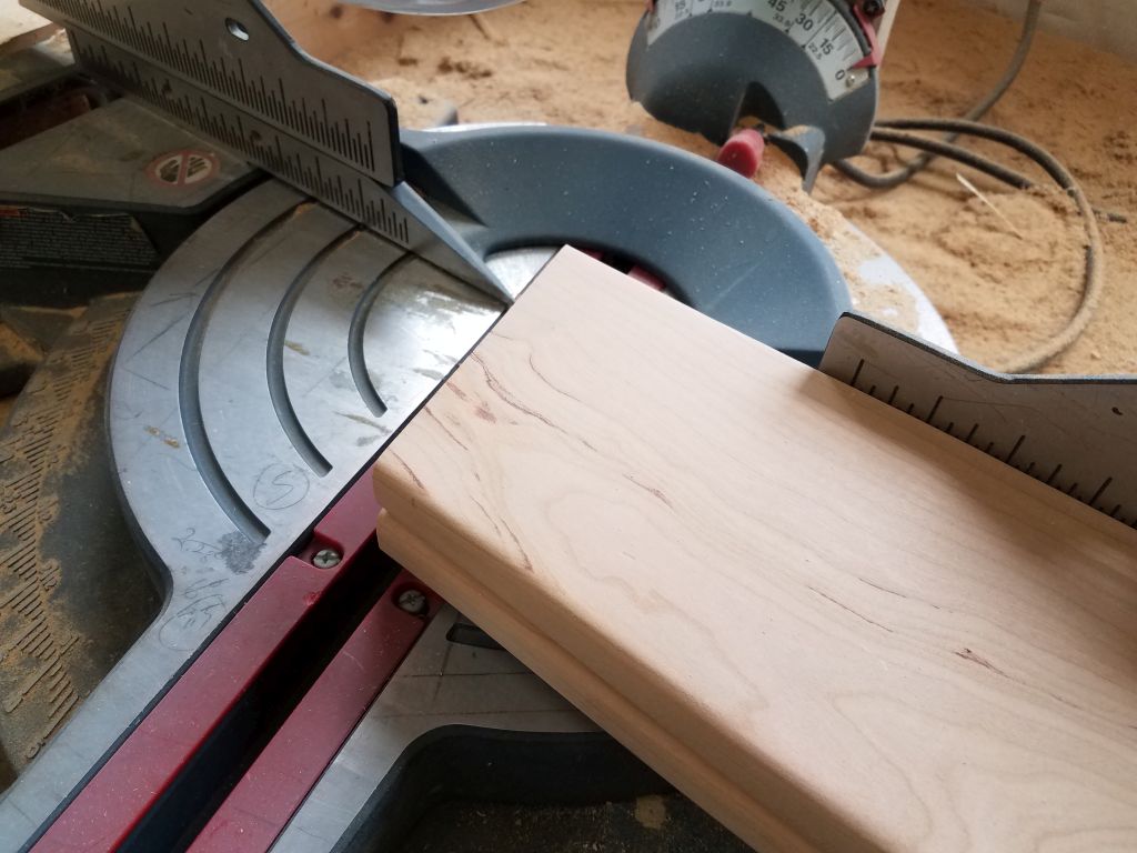
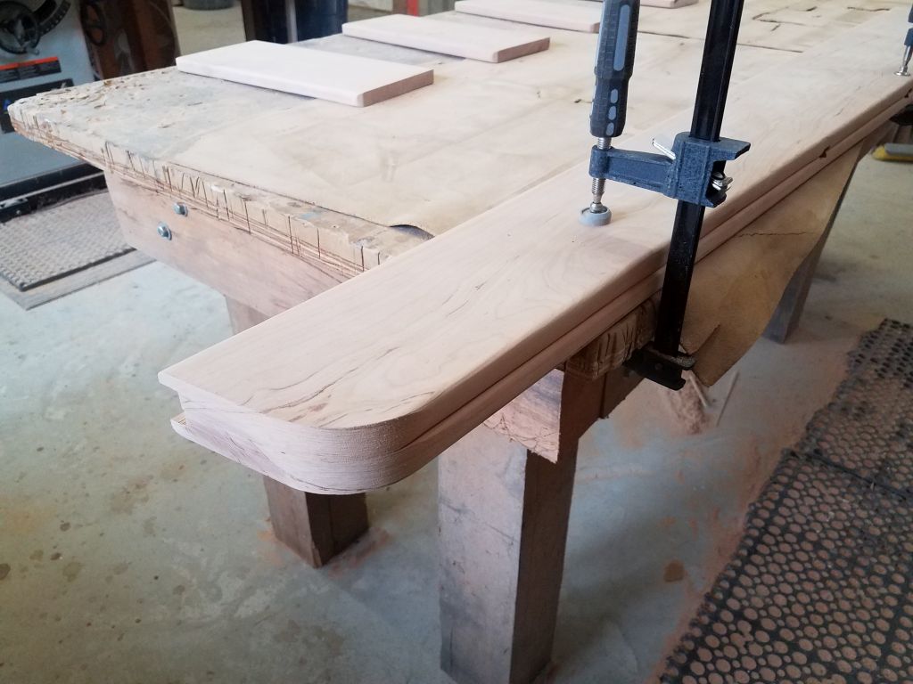
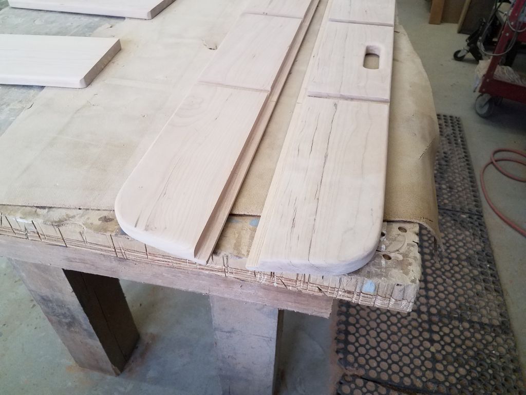
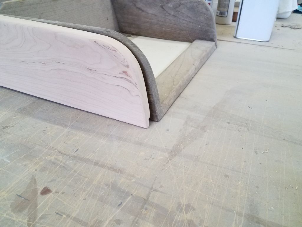
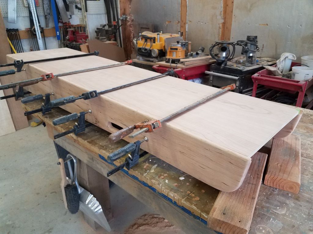
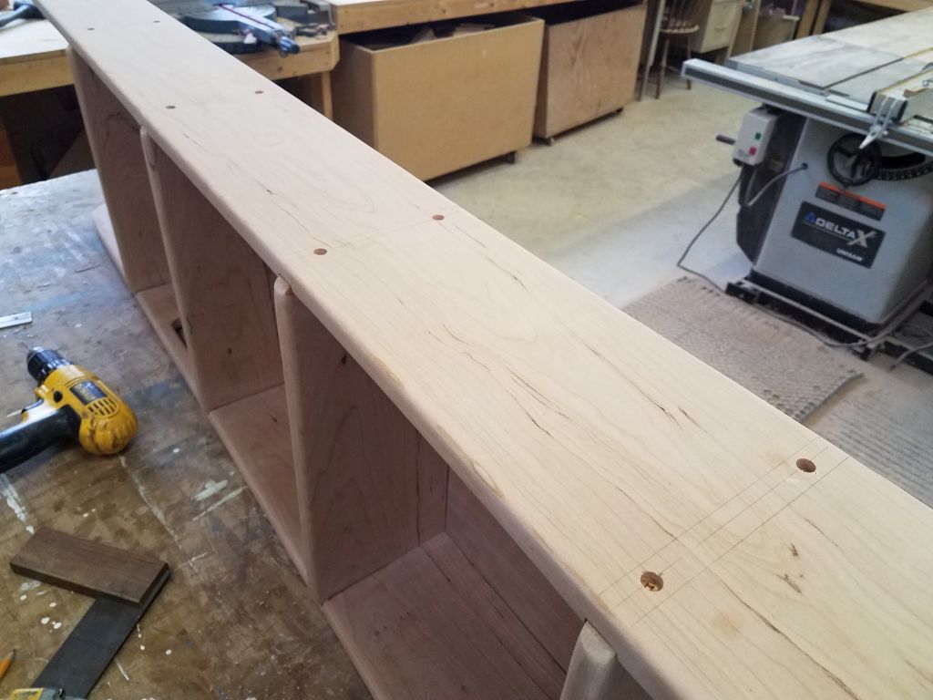
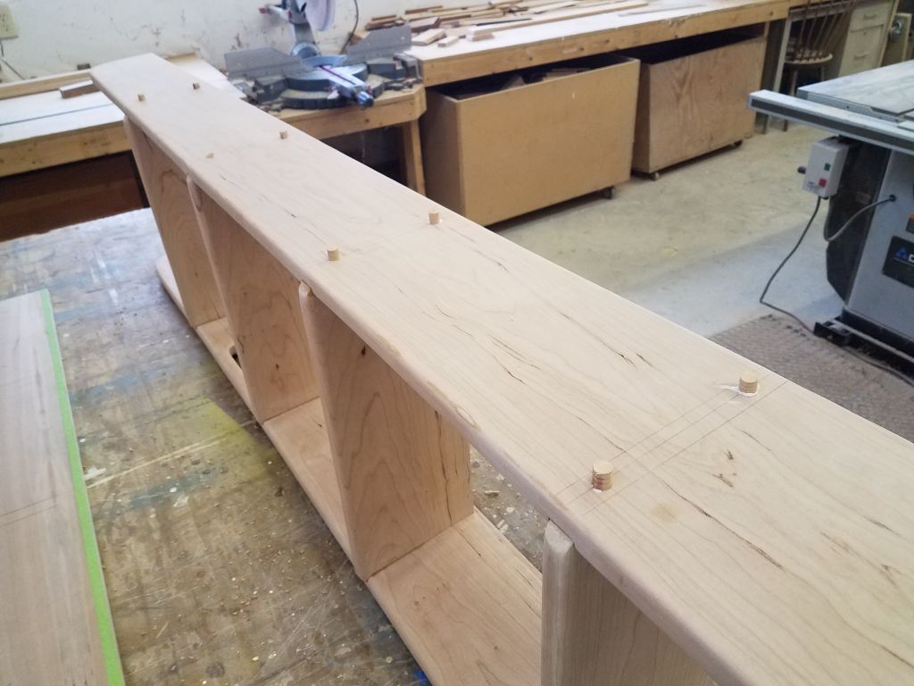
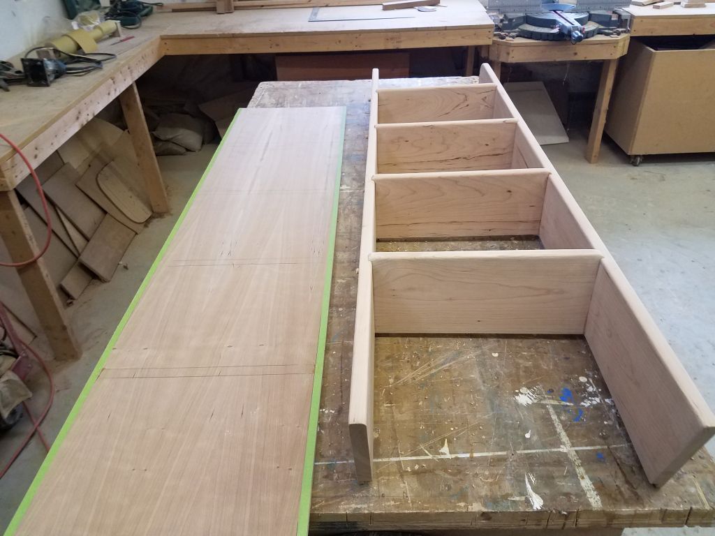
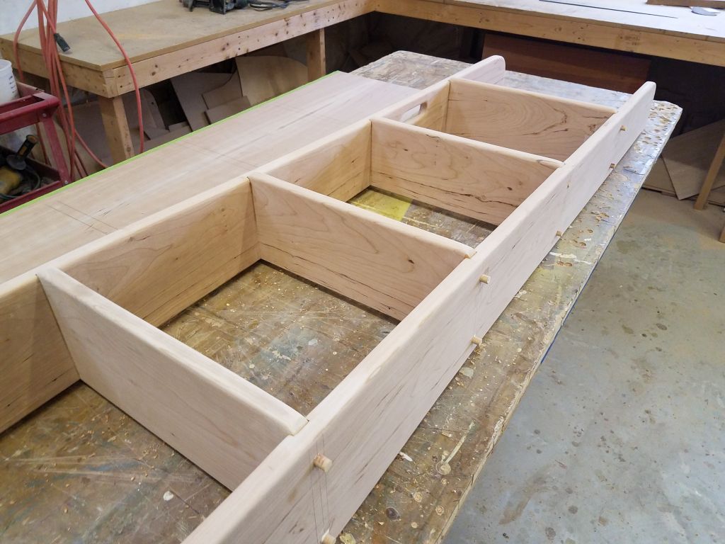
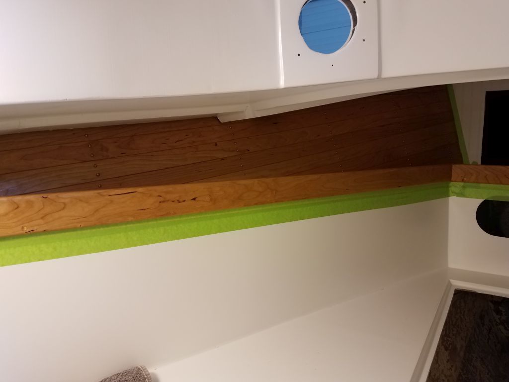
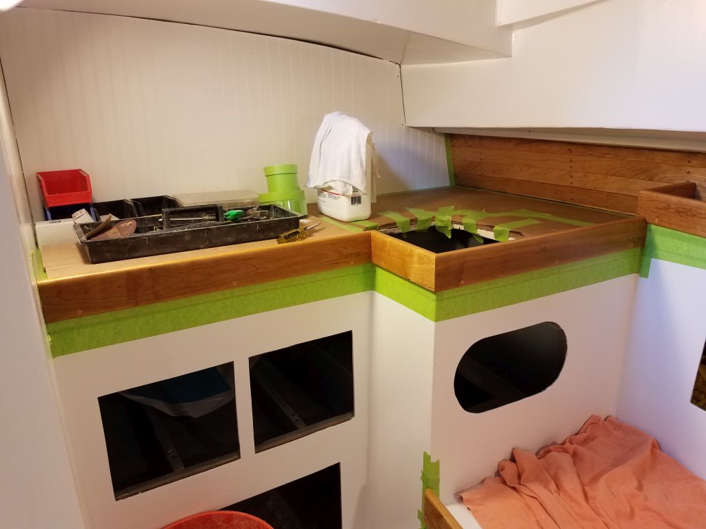
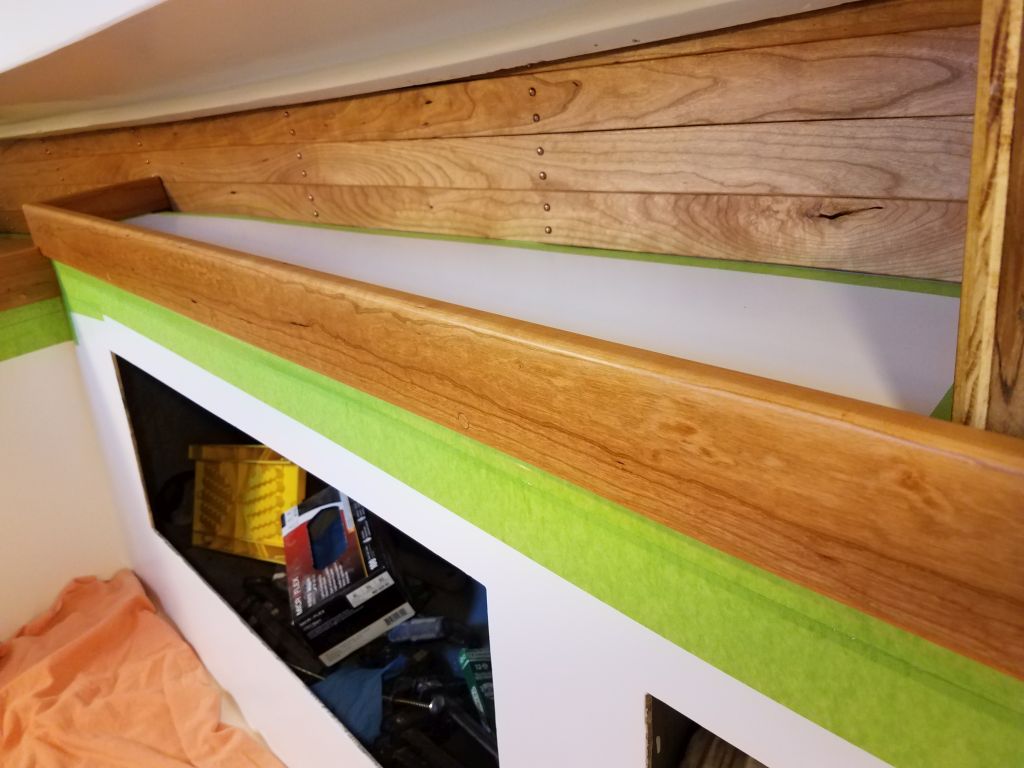
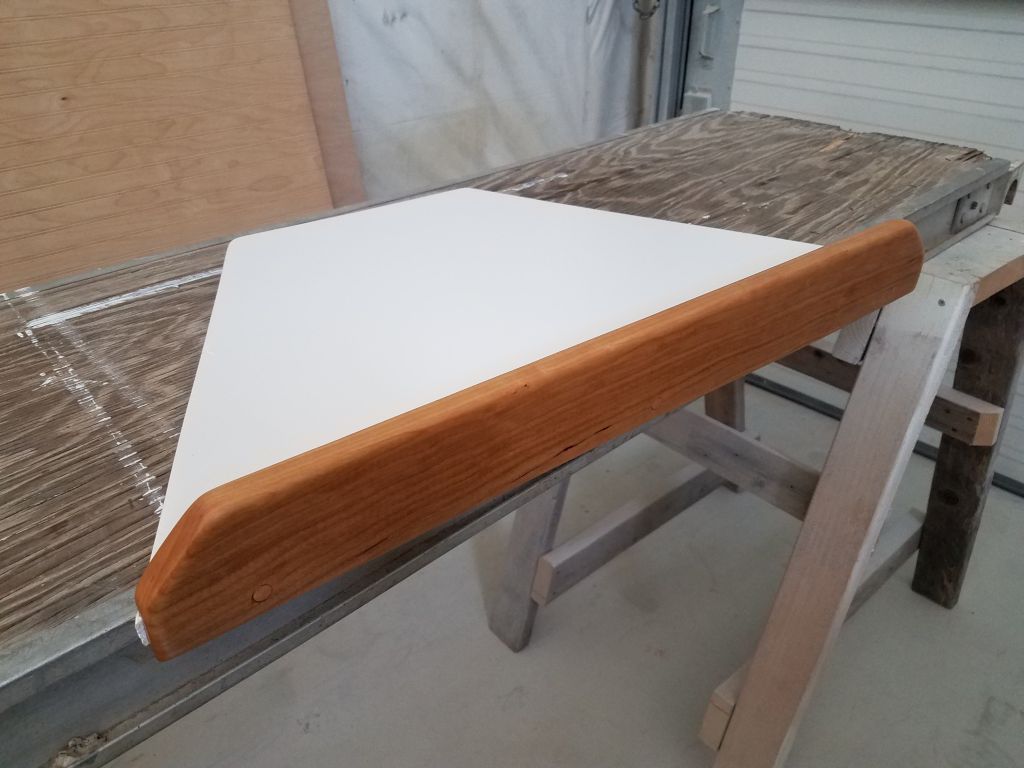
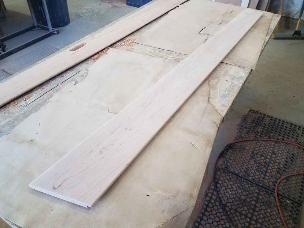
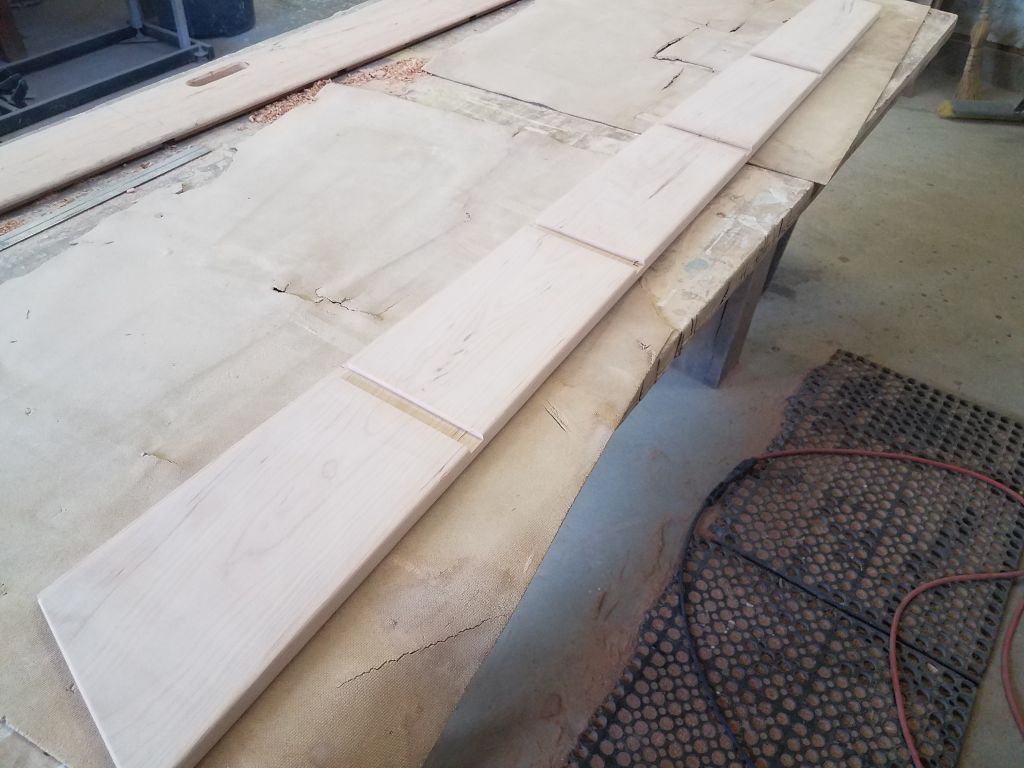
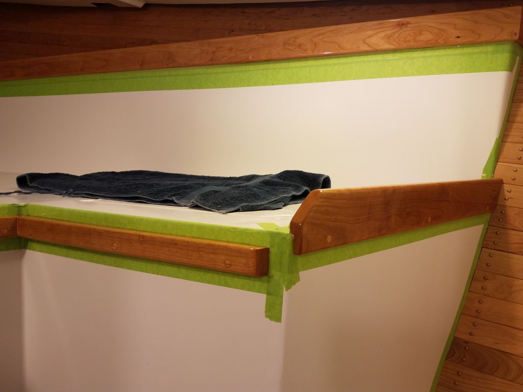
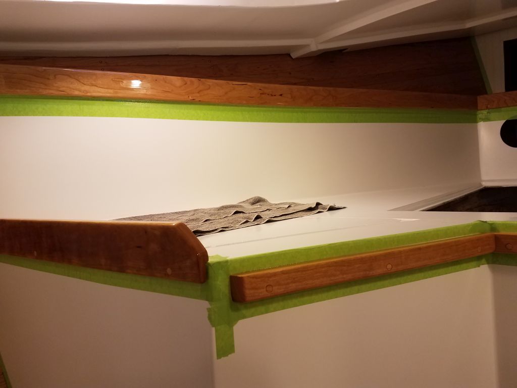
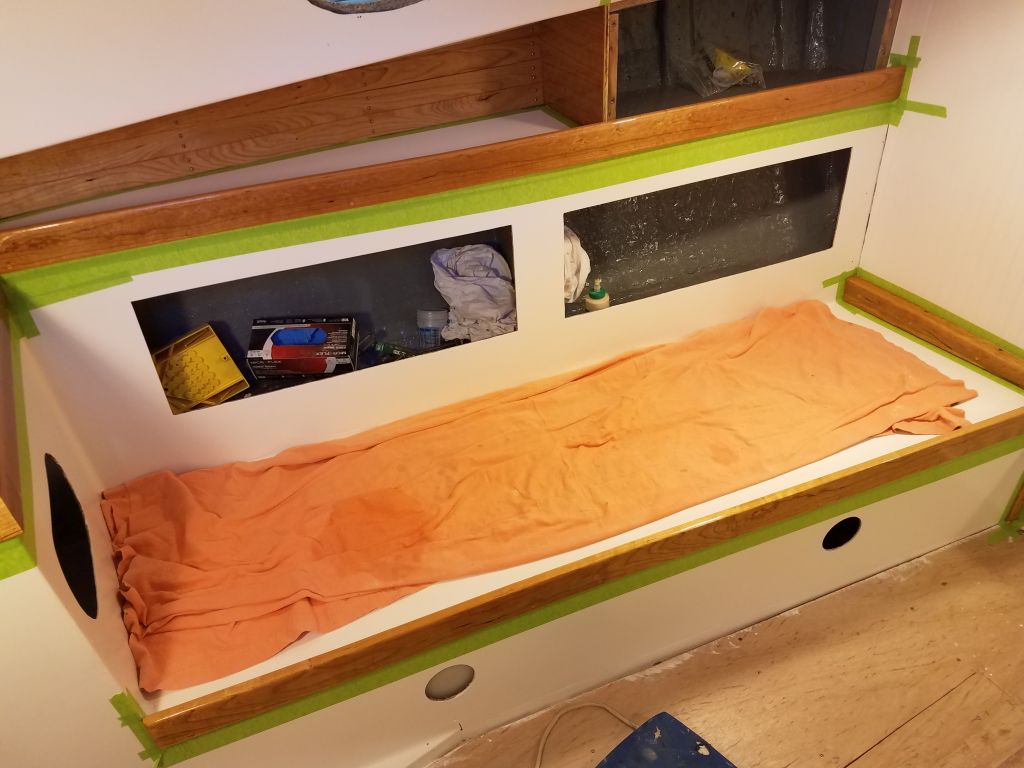
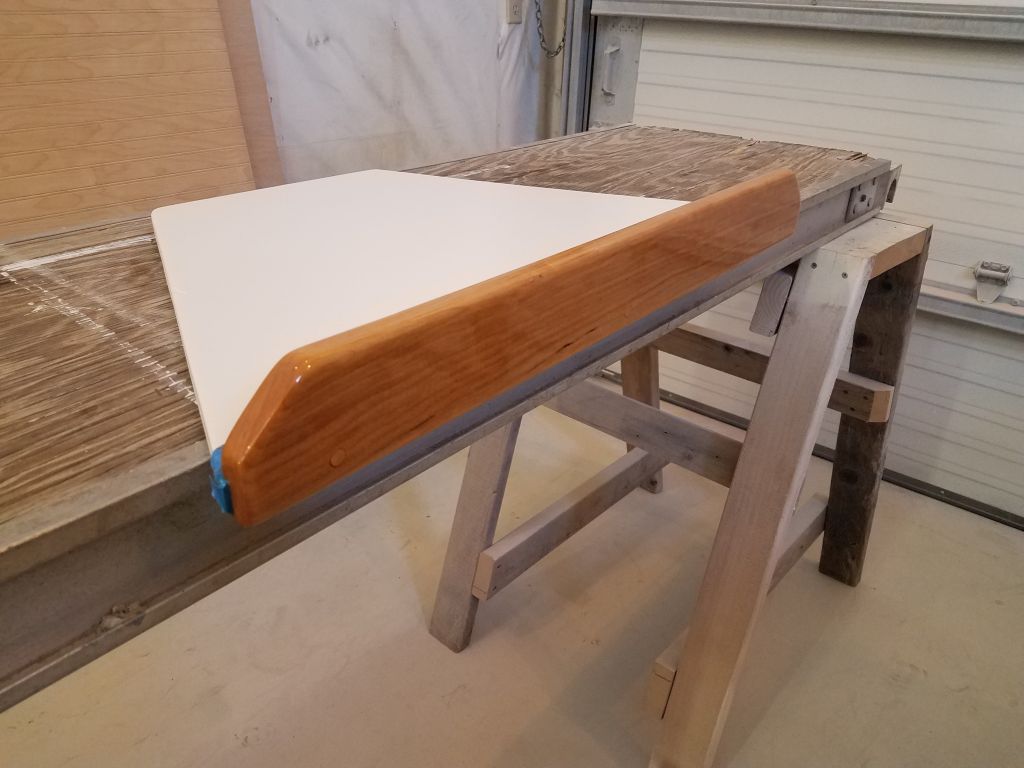
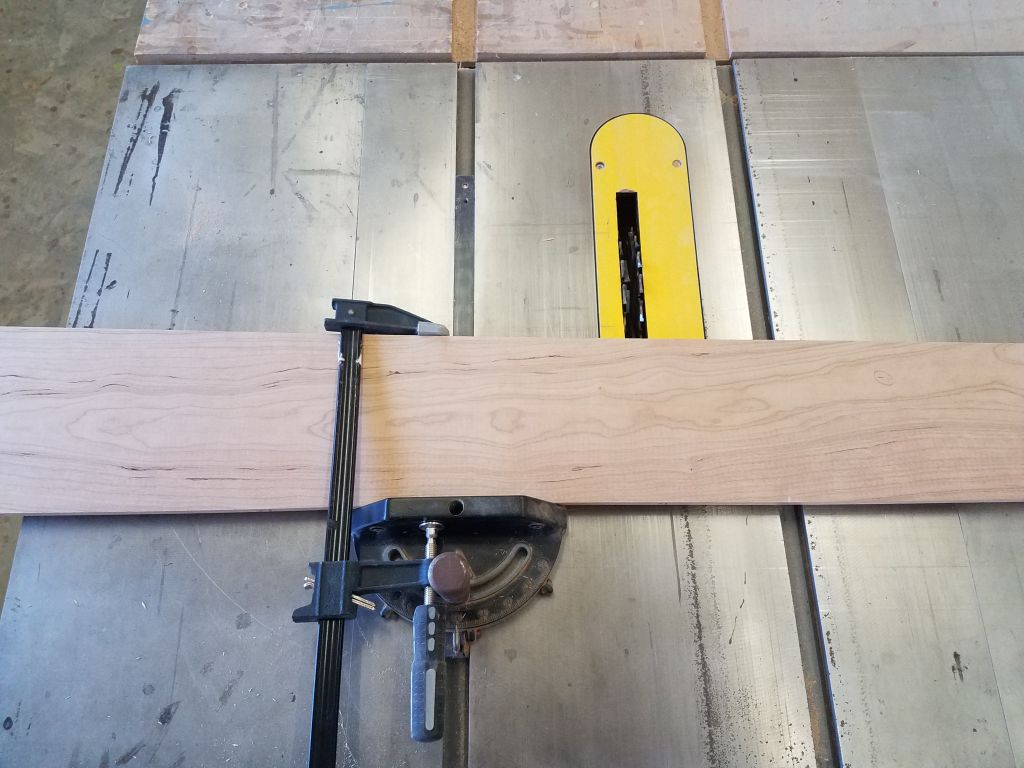
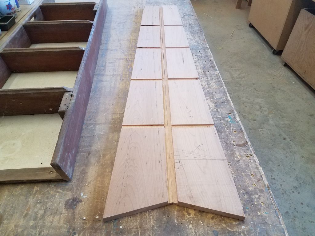
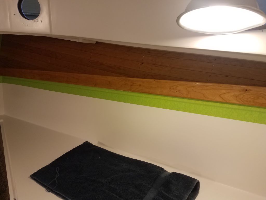
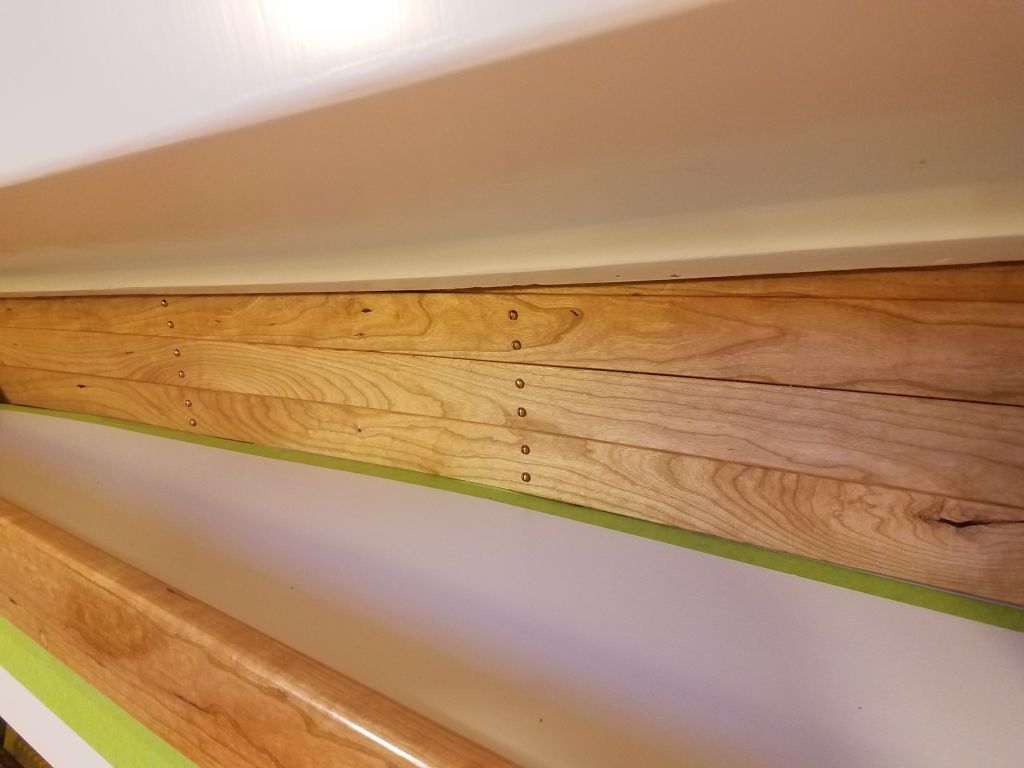
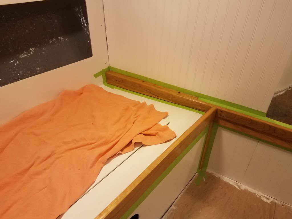
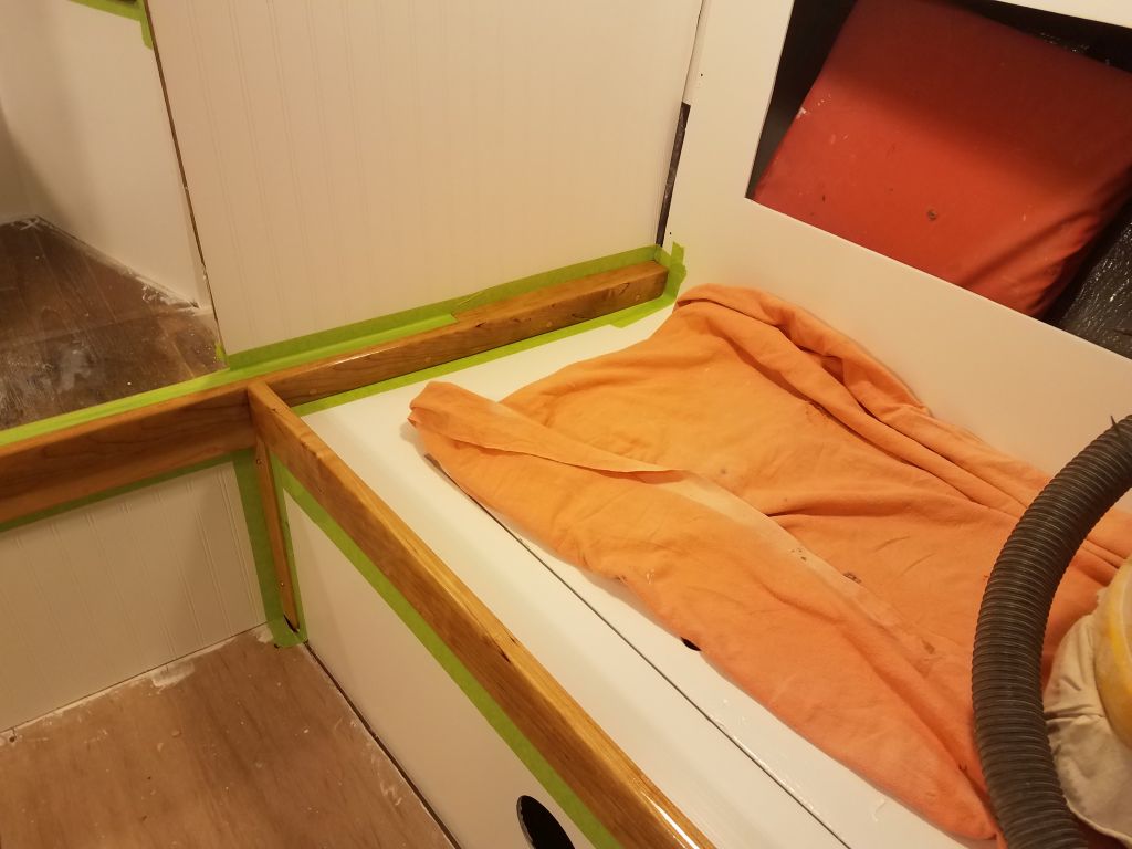
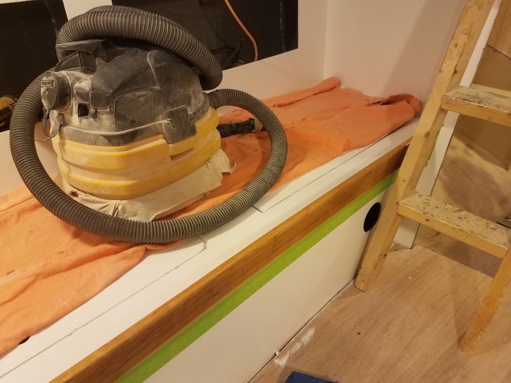
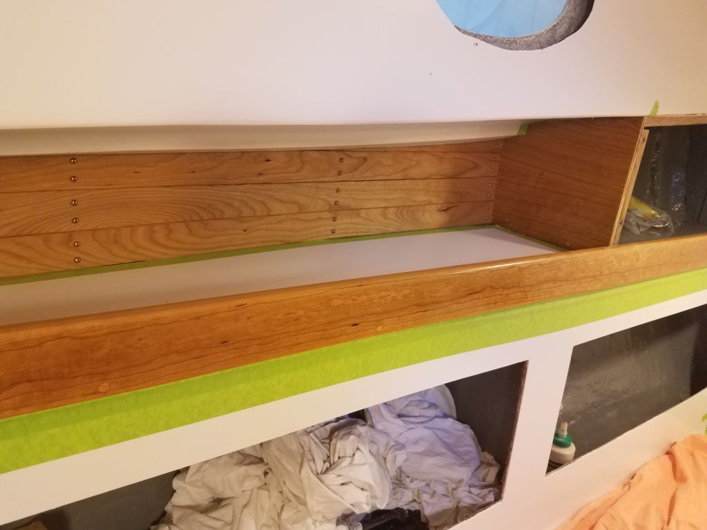
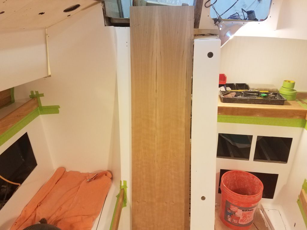
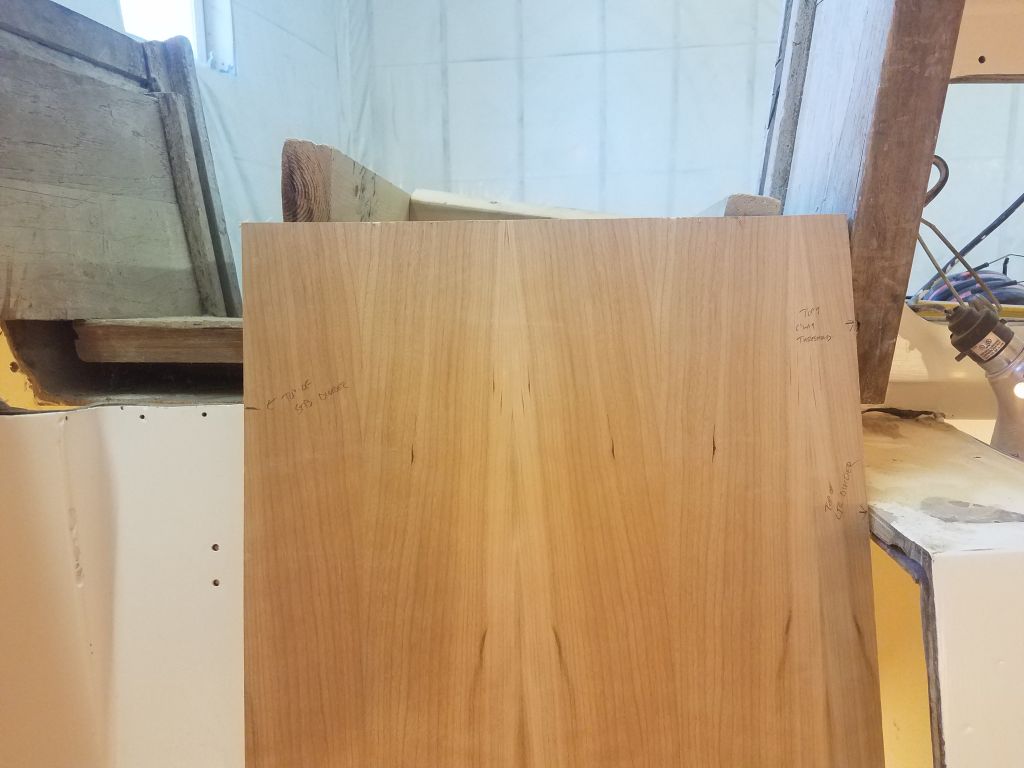
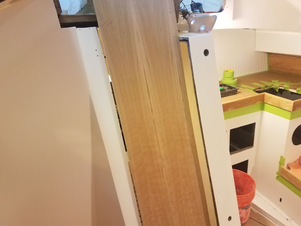
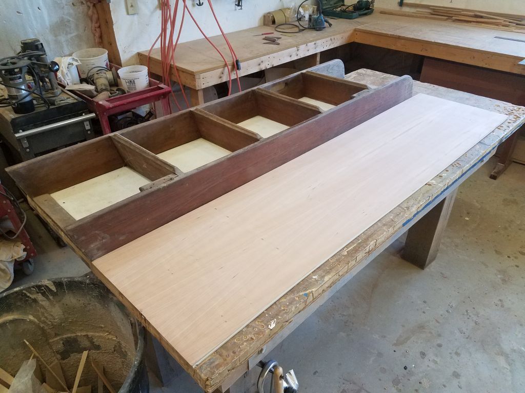
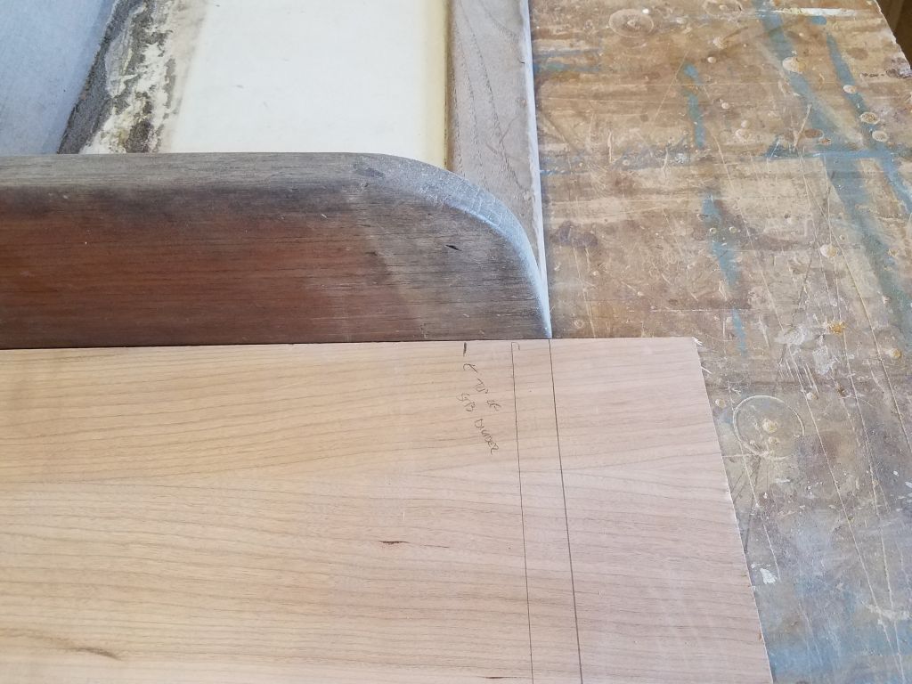
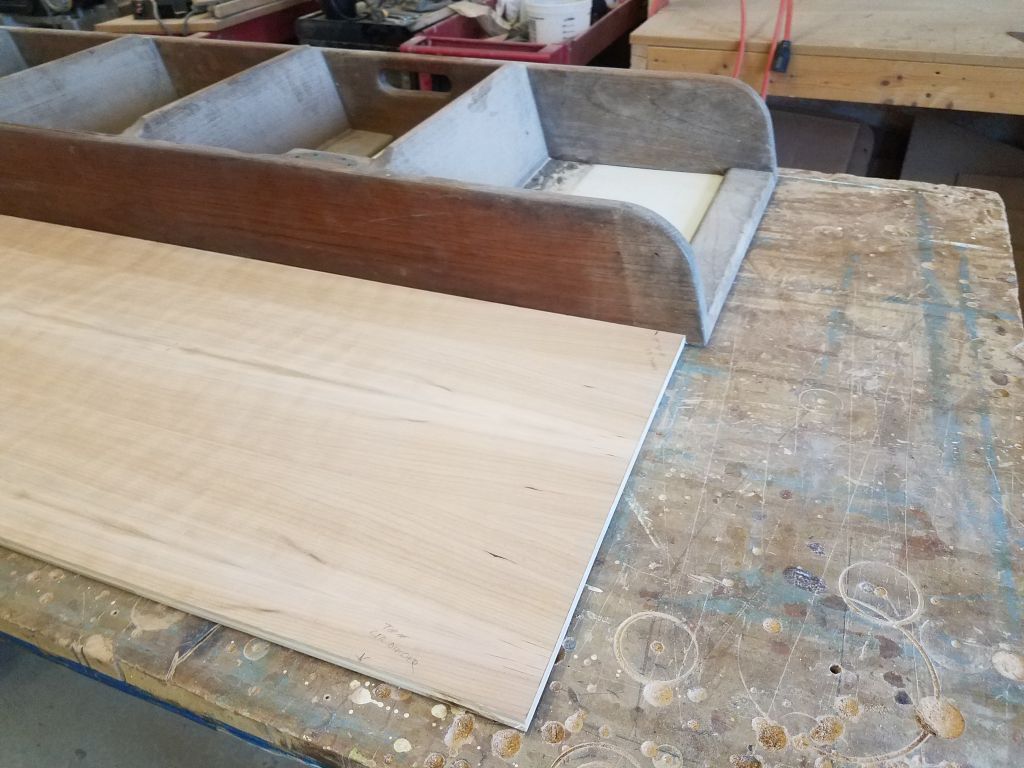
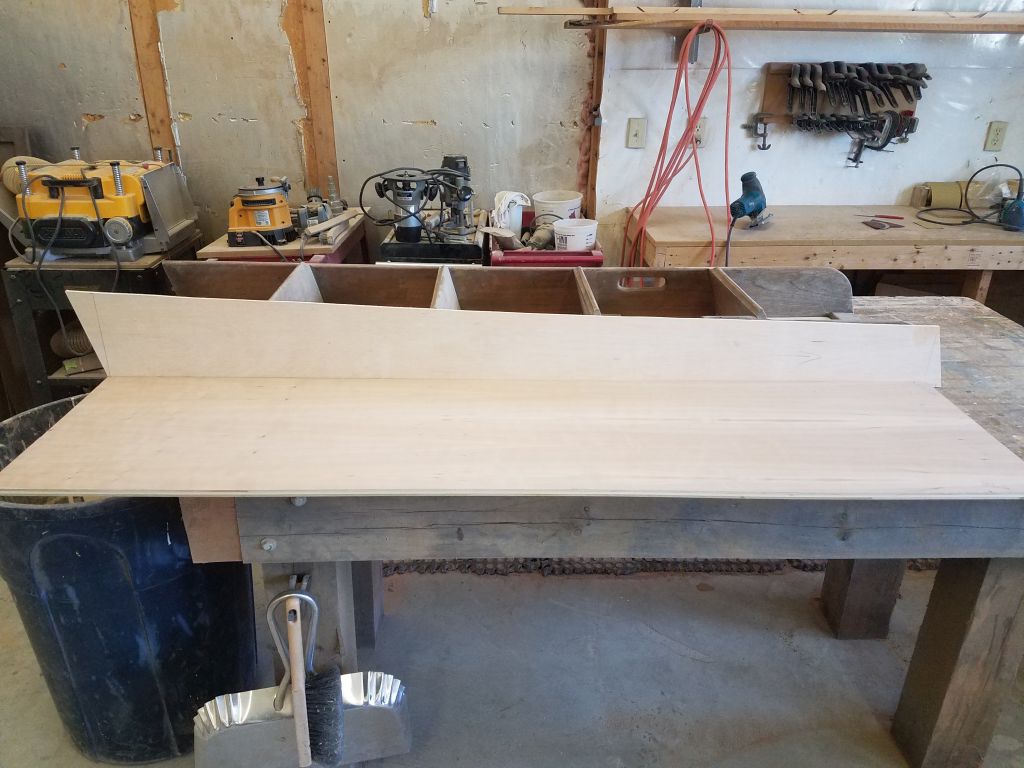
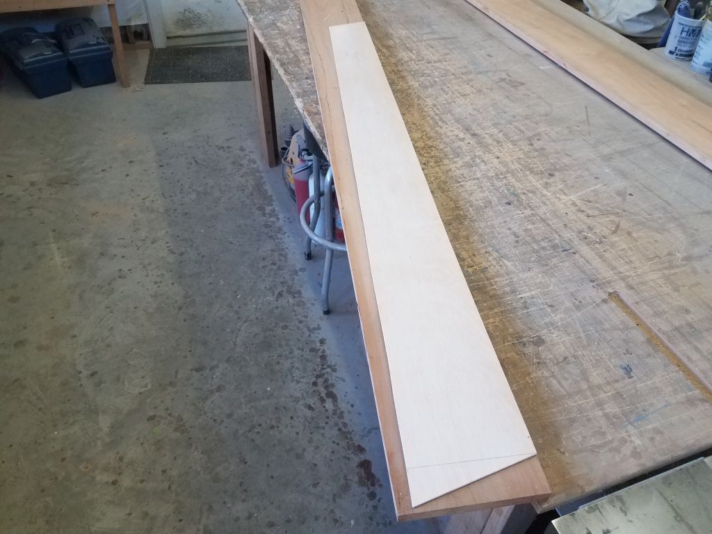
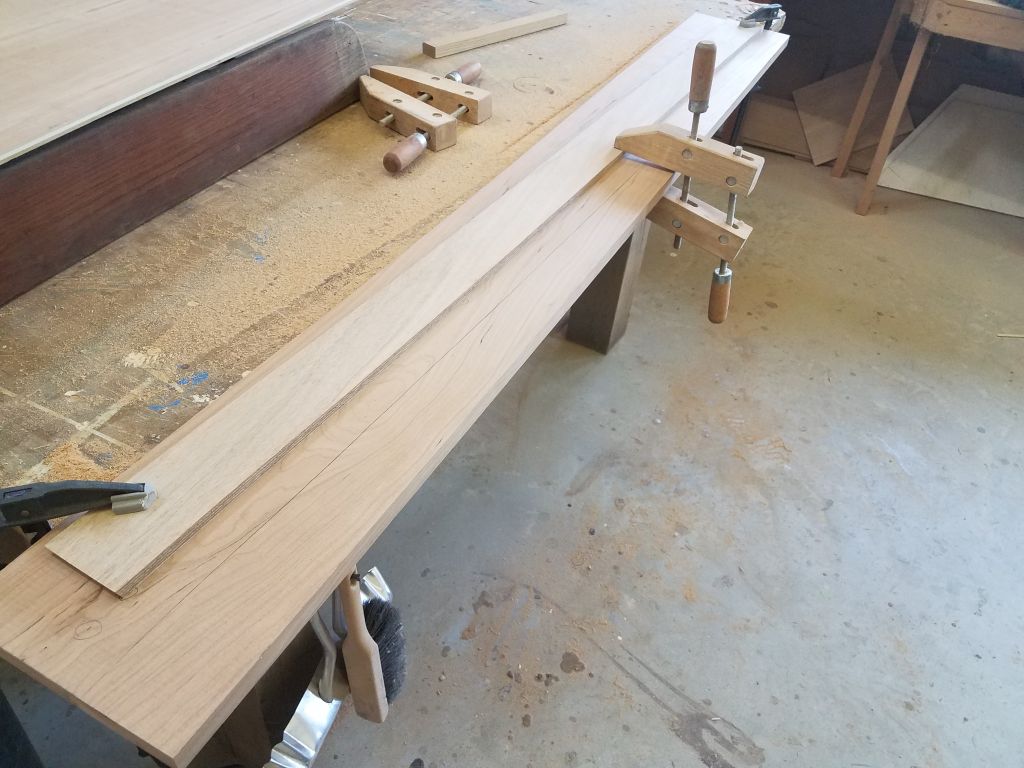
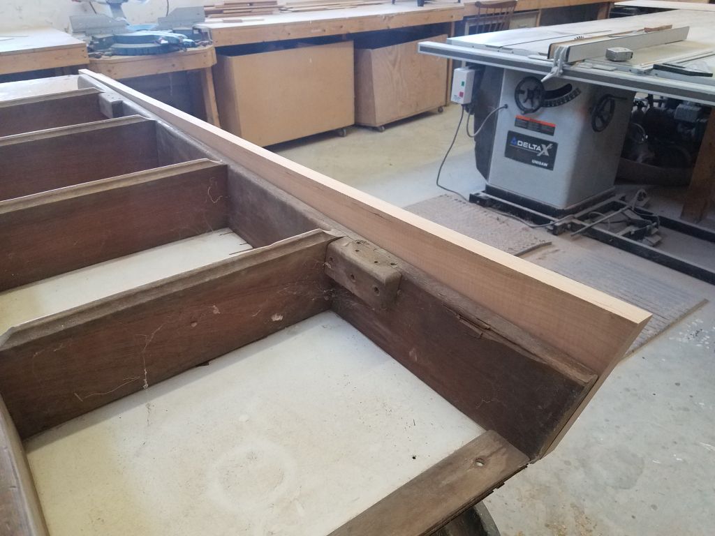
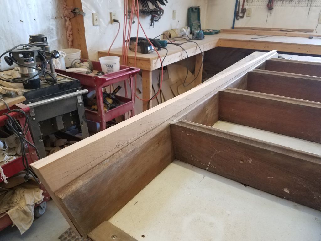
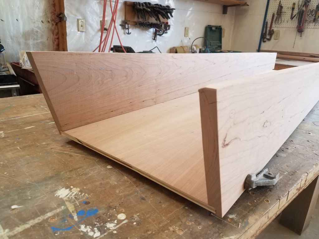
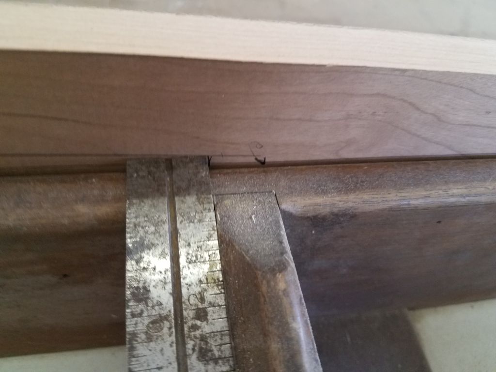
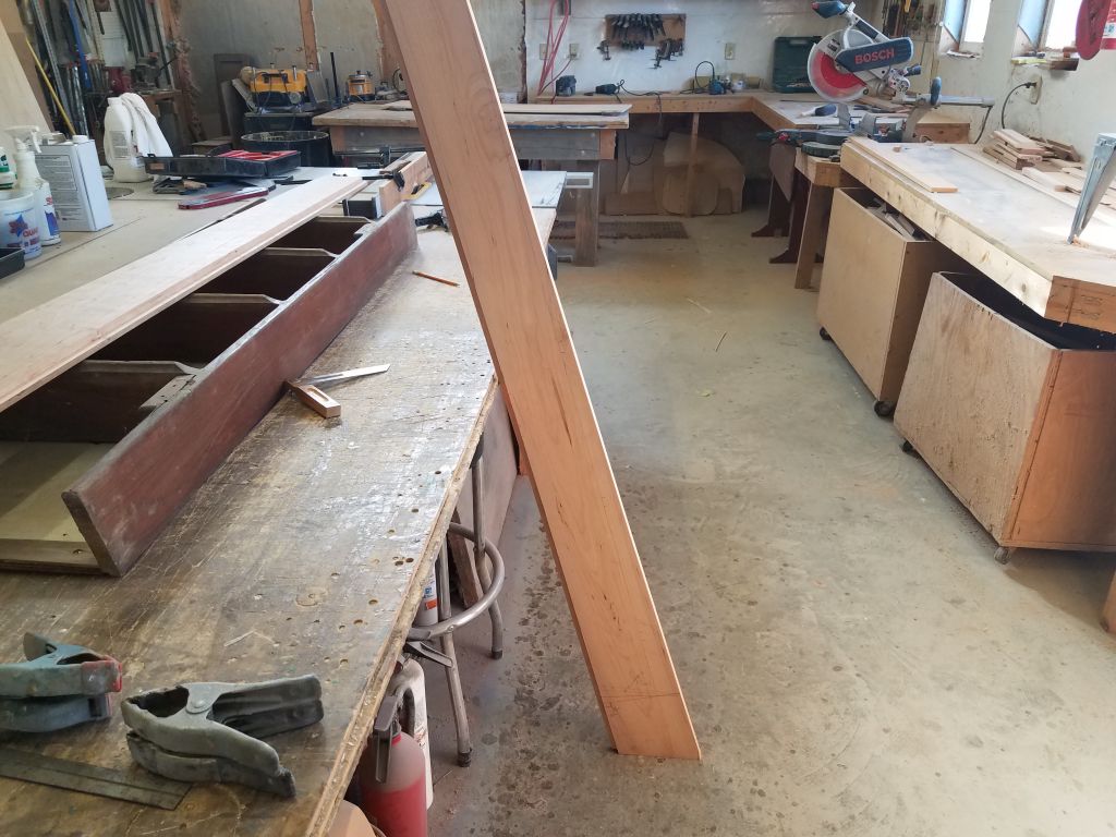
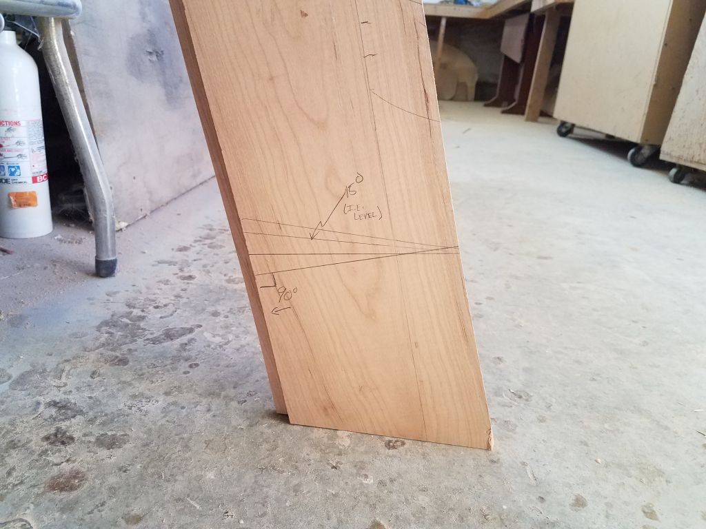
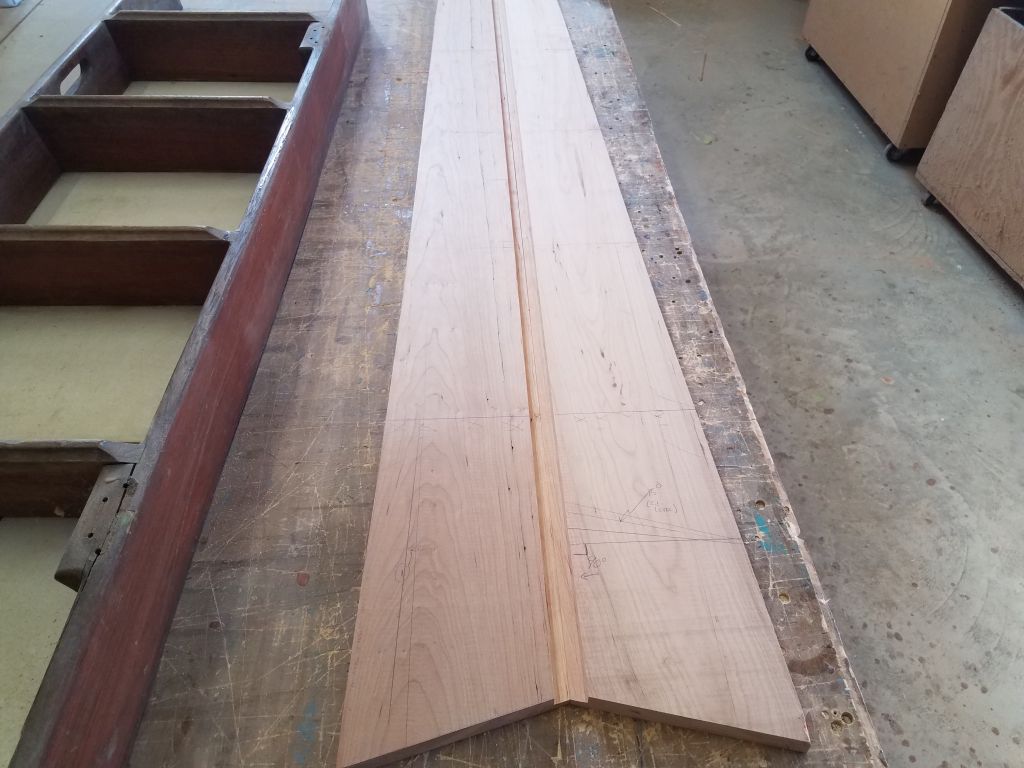
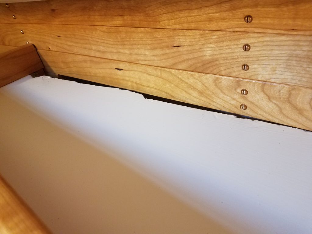
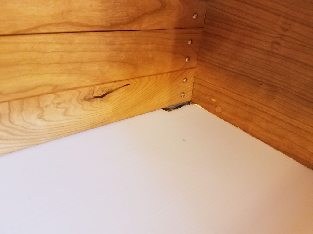
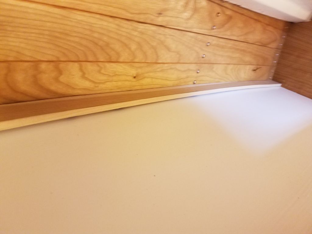
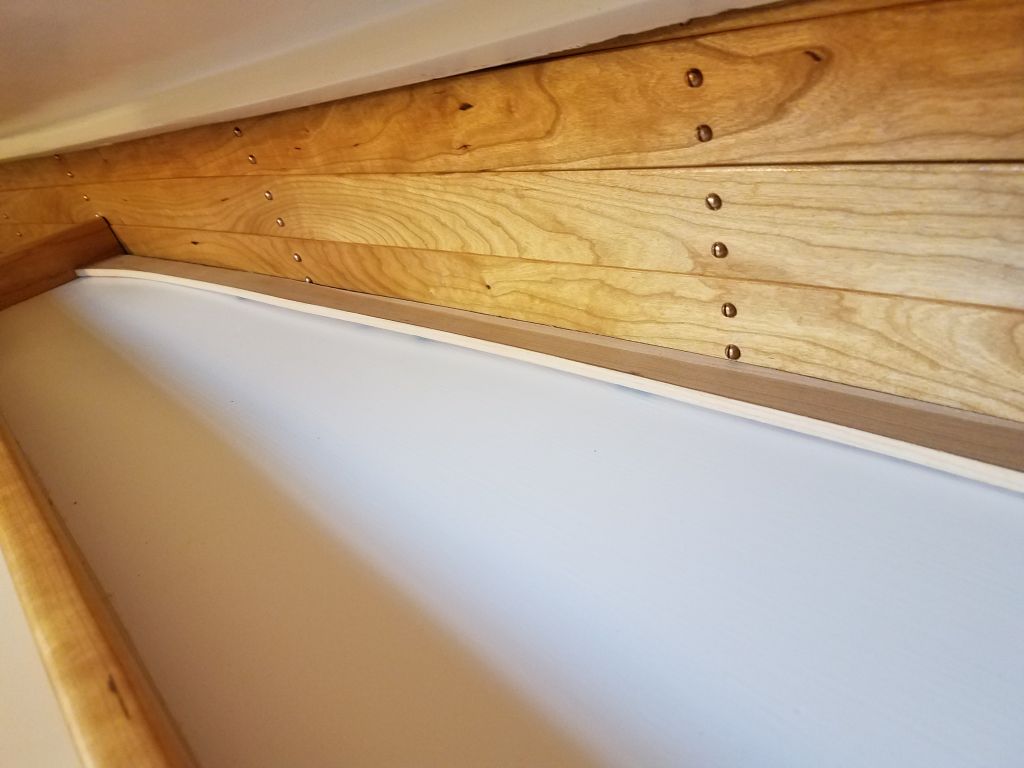
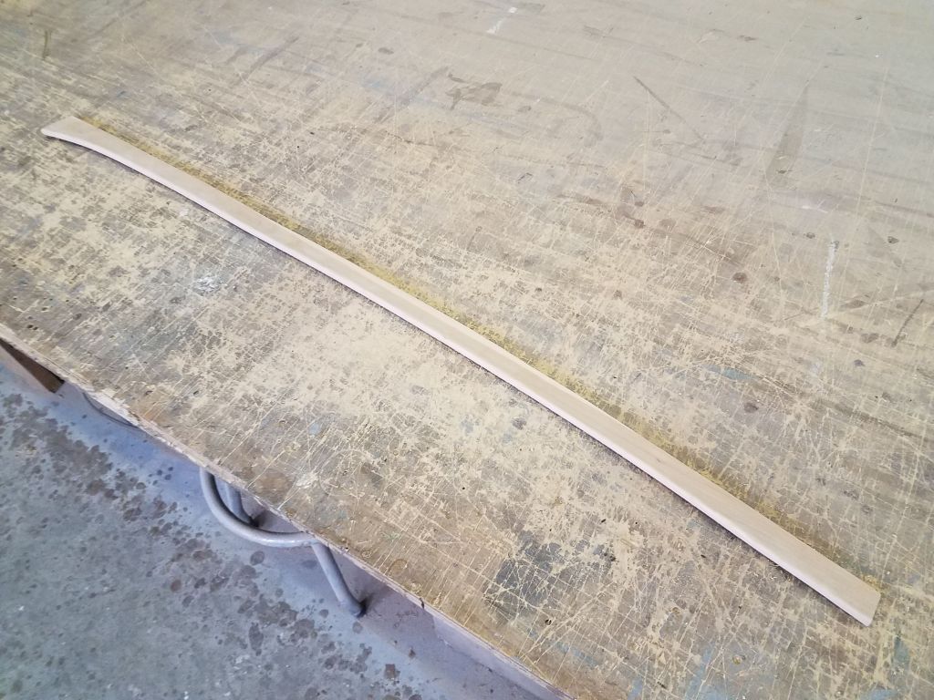
Next, I prepared a piece of trim to cover the ragged, exposed edge of the shelf above the port settee in the main cabin.  I’d decided it would be best to paint this trim, the better to fit in with the painted shelf rather than highlight the trim with varnish, so I was able to use a piece of otherwise-undesirable cherry stock (i.e. the light-colored sapwood from a wider piece) to mill the trim, which I cut to fit using a plywood template I’d made earlier.  After cutting and sanding the trim to fit, I set it aside to await primer and paint.

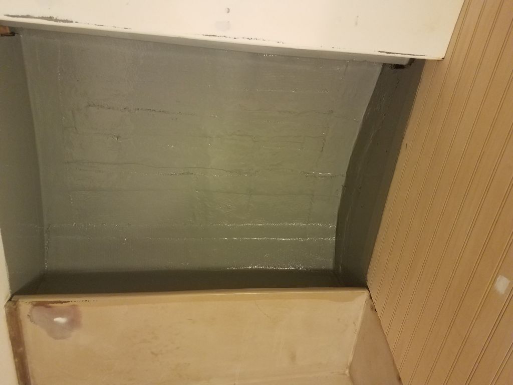
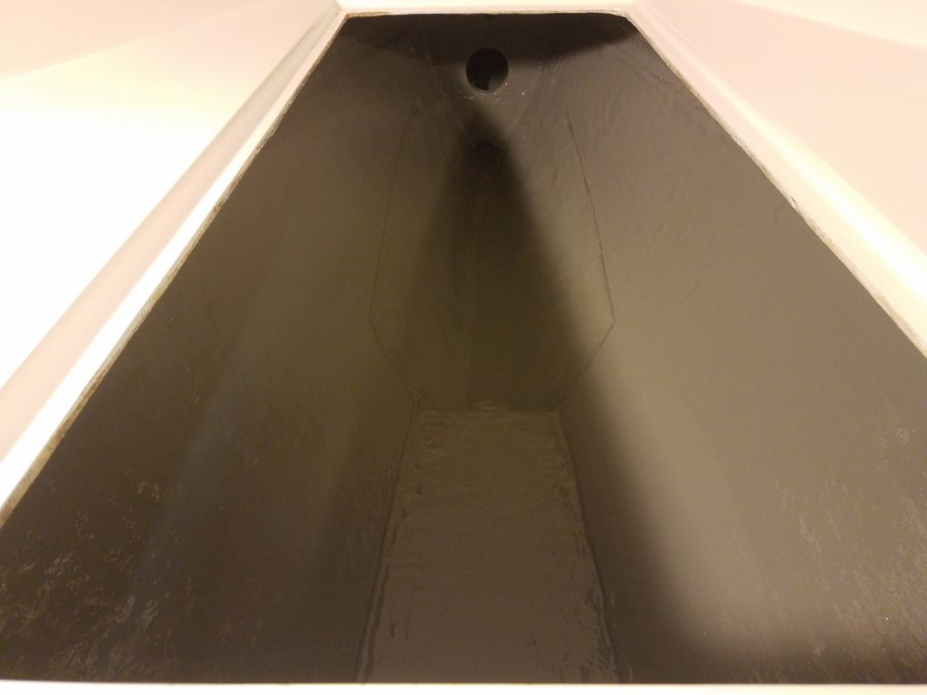
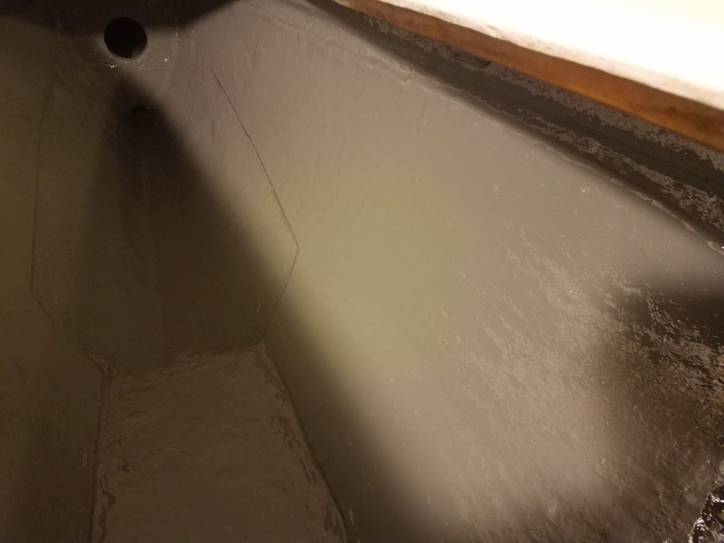
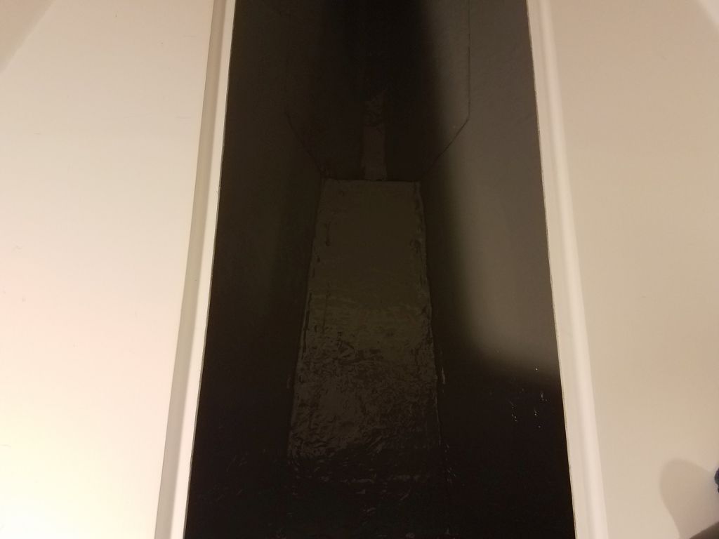
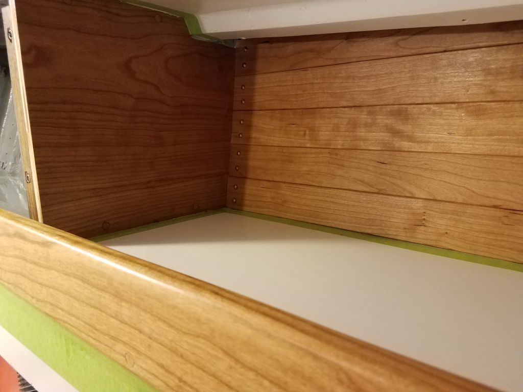
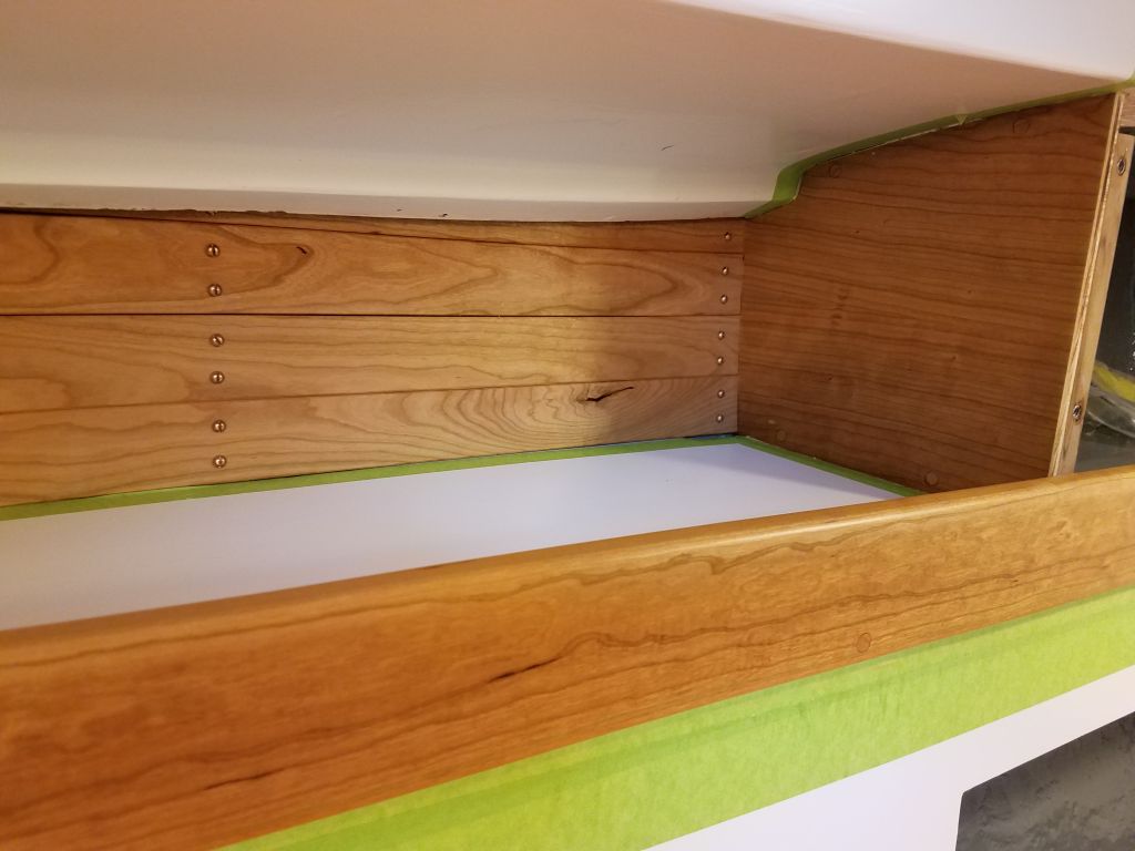
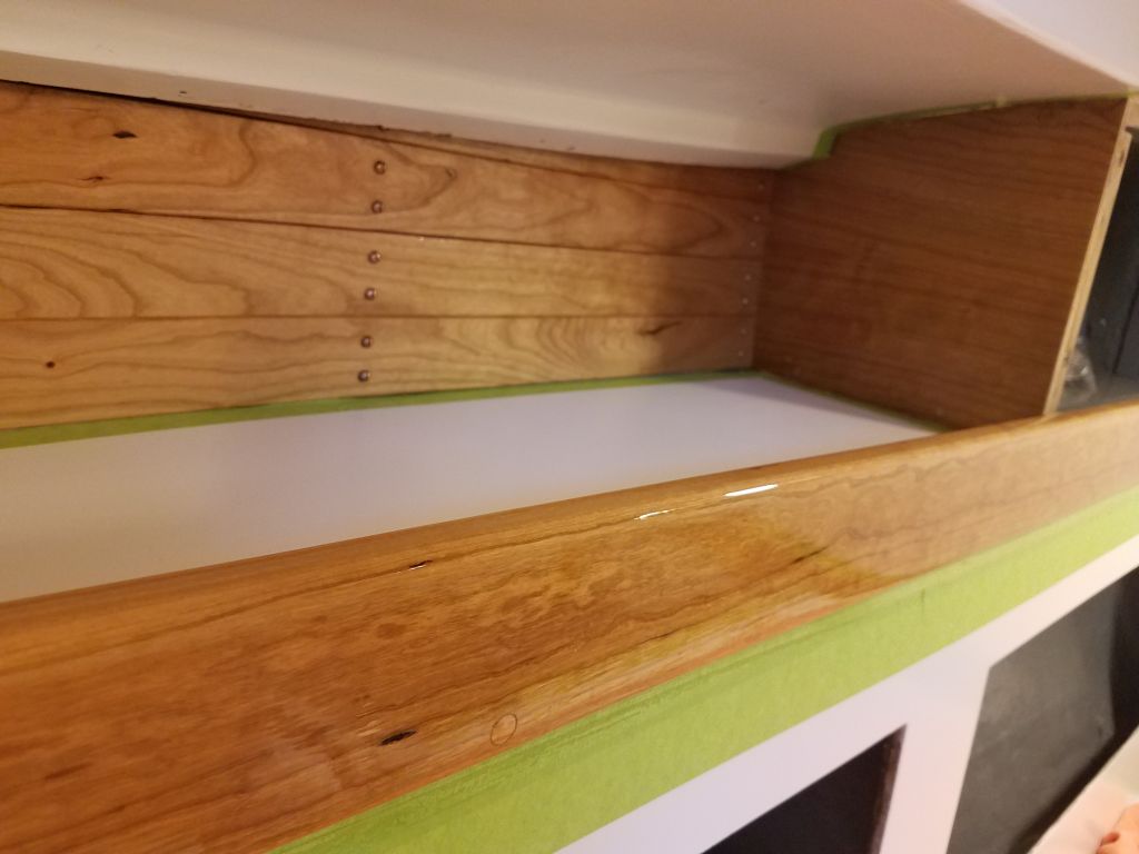
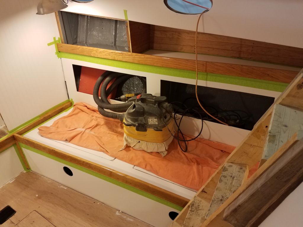
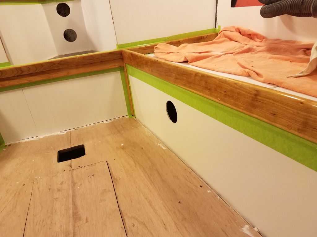
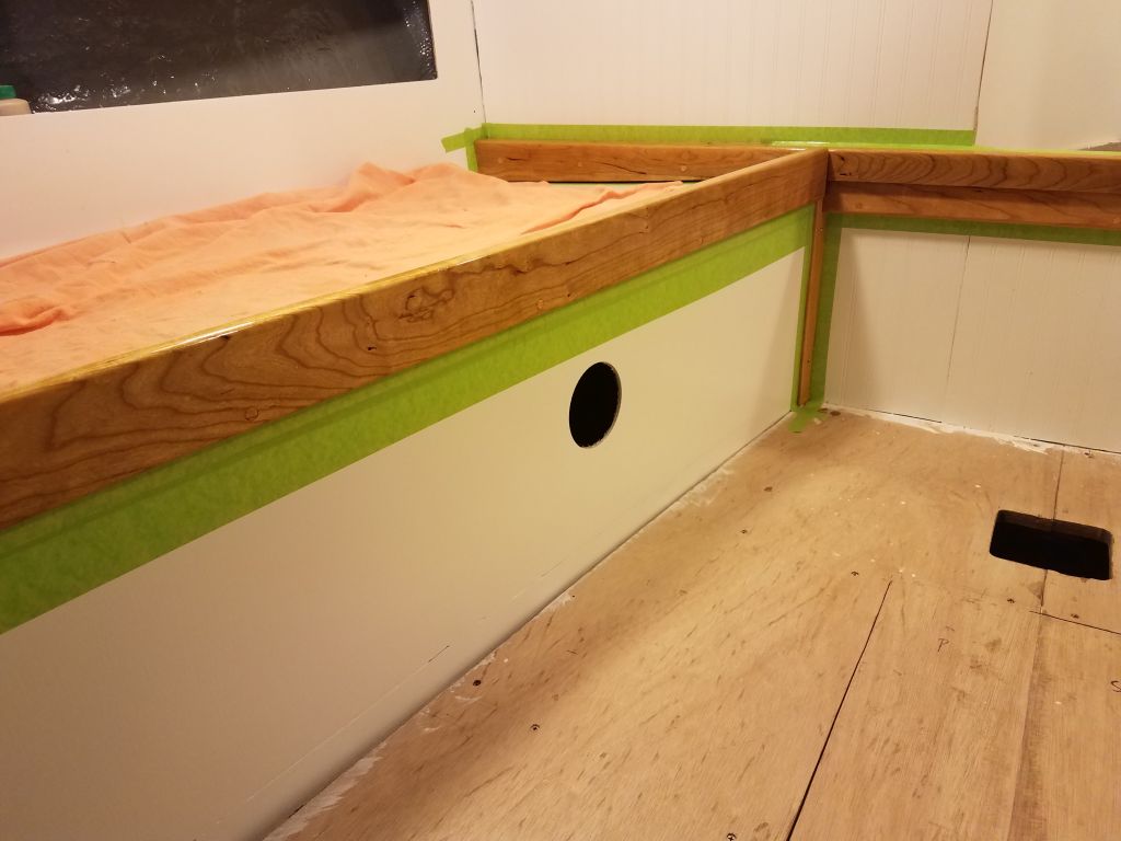
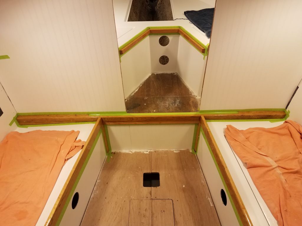
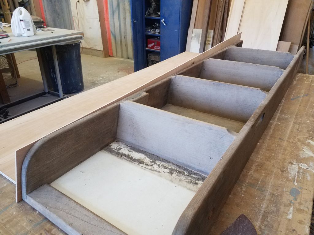
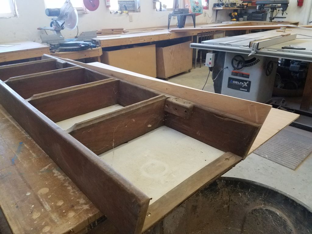
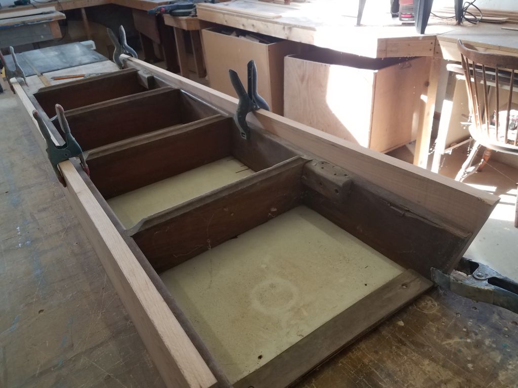
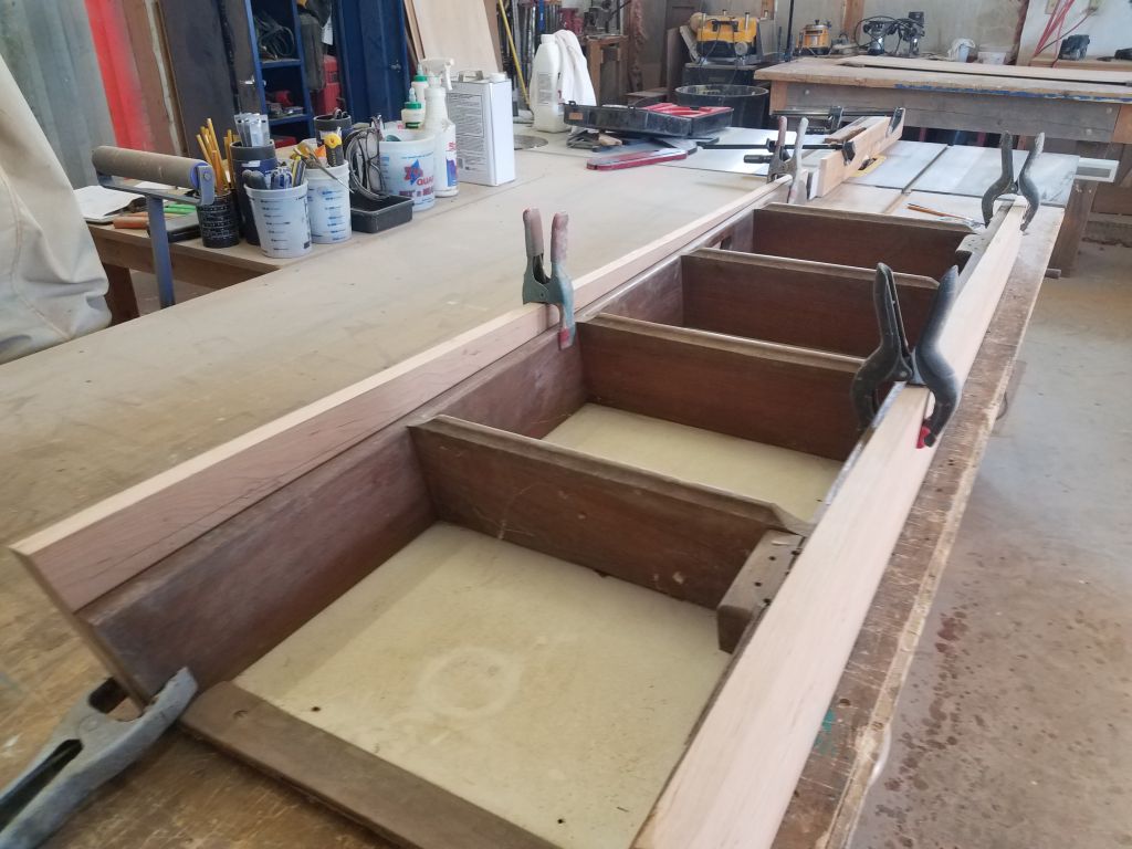
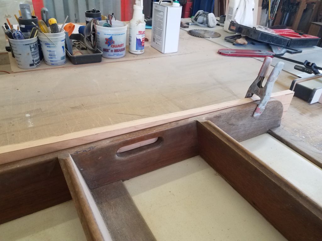
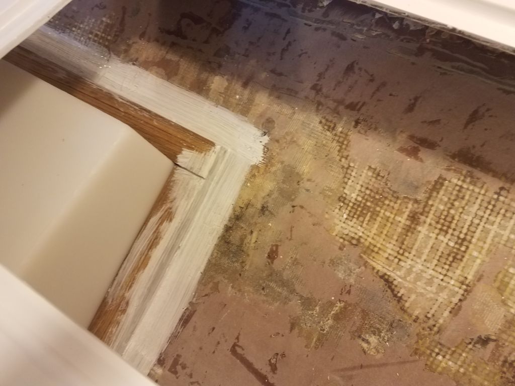
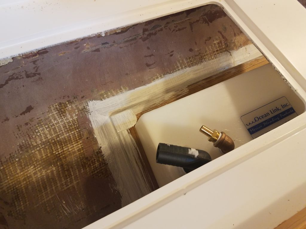
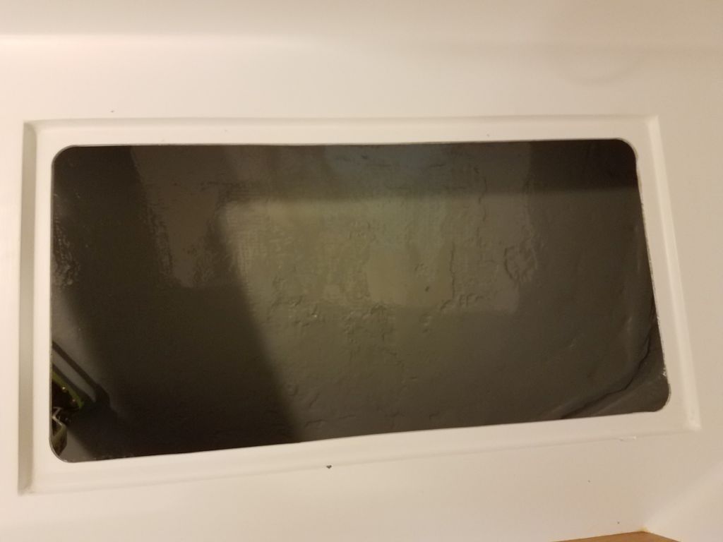
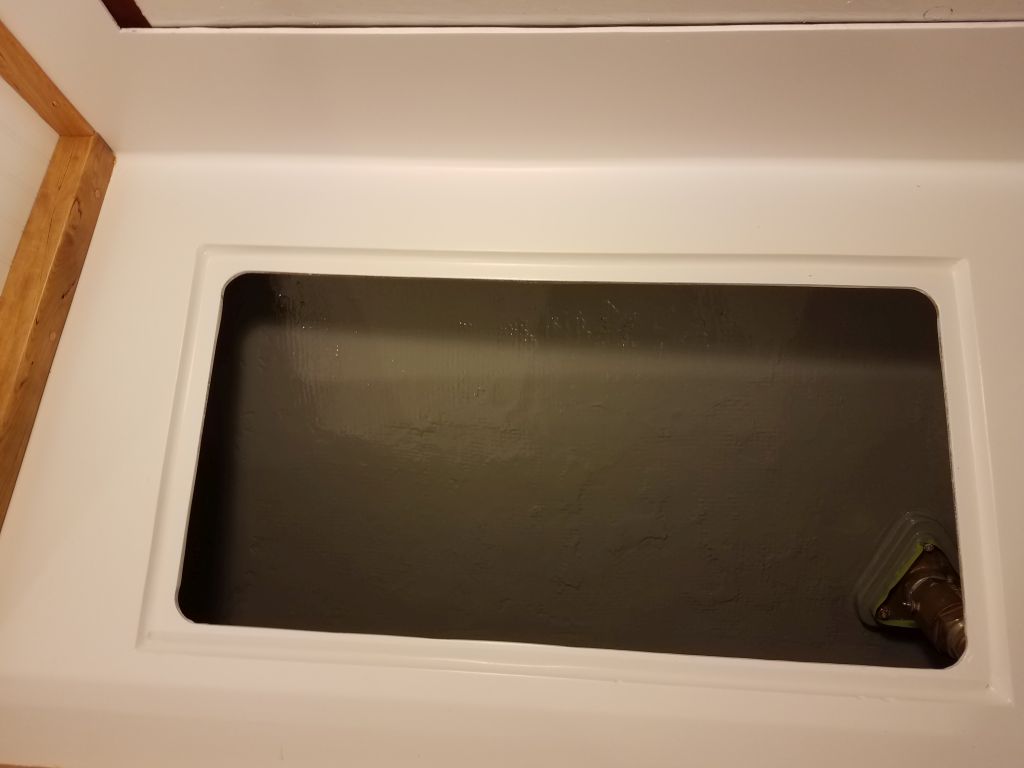
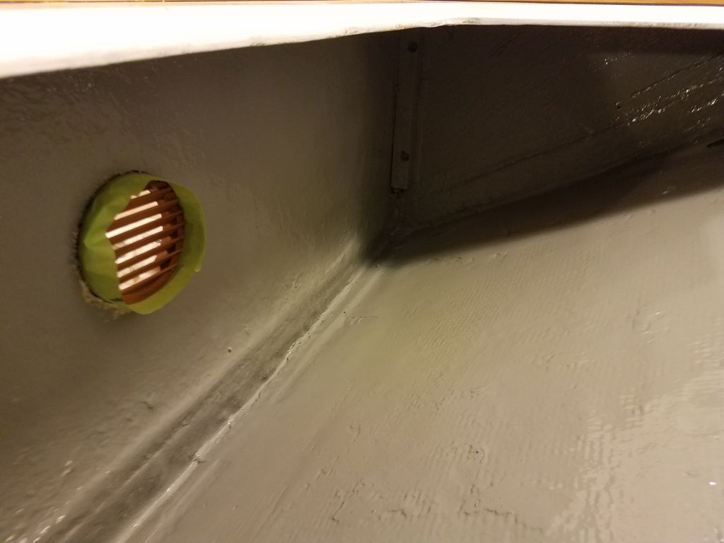
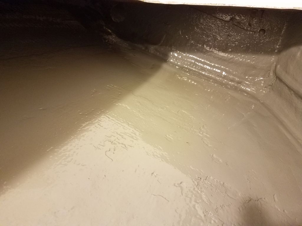
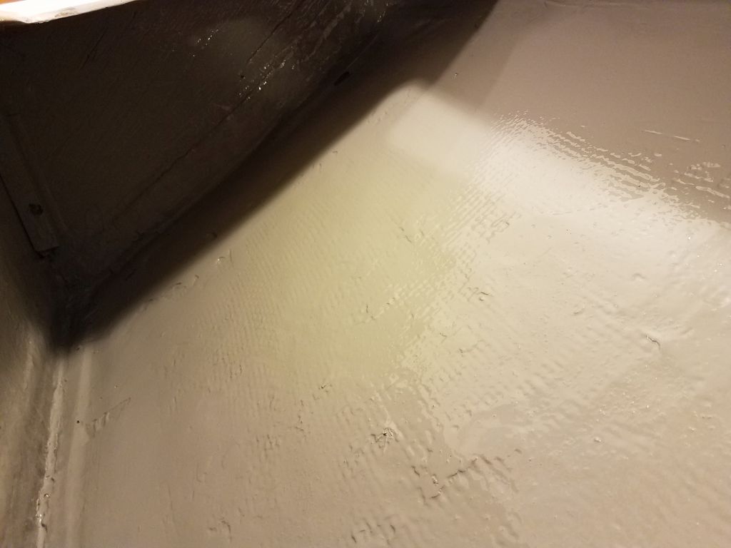
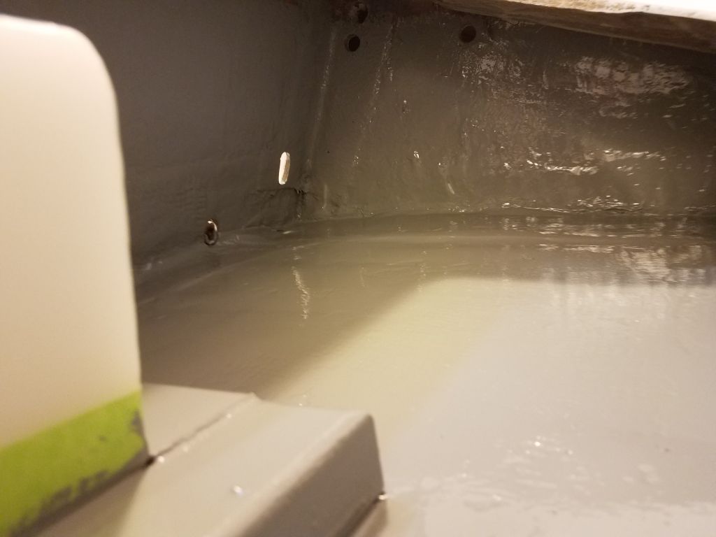
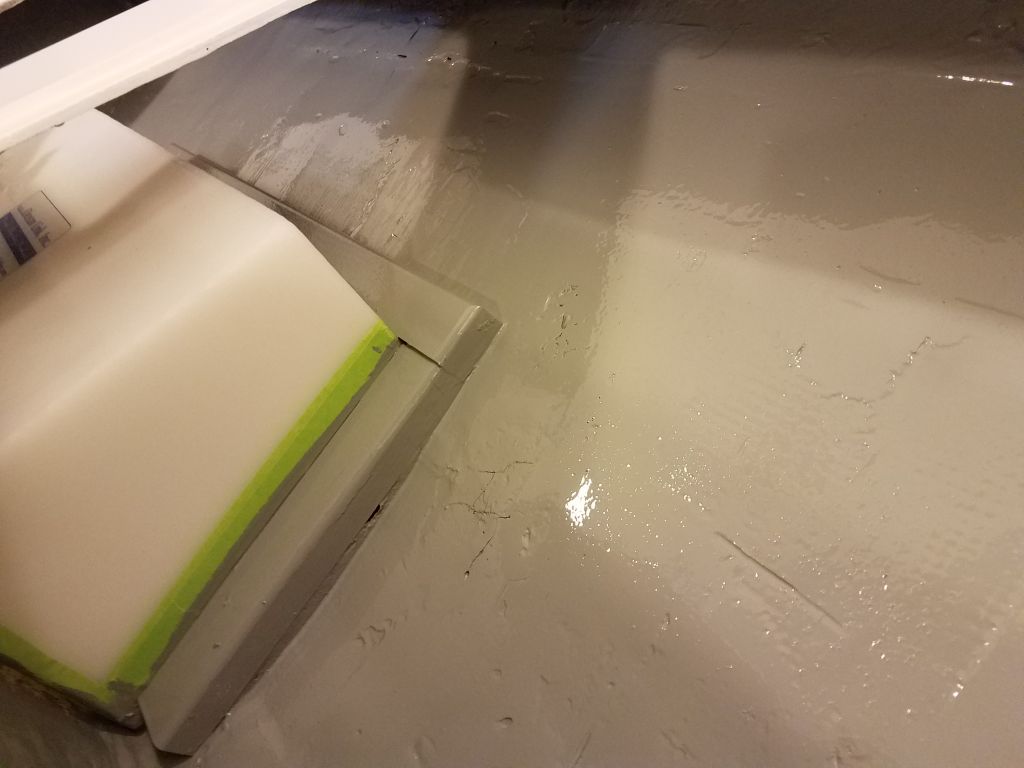
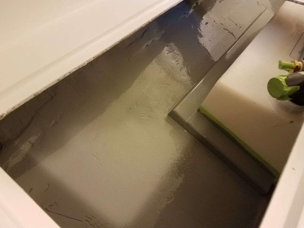
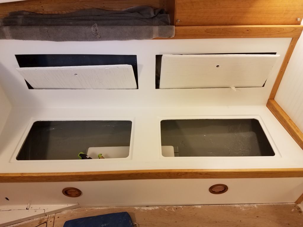
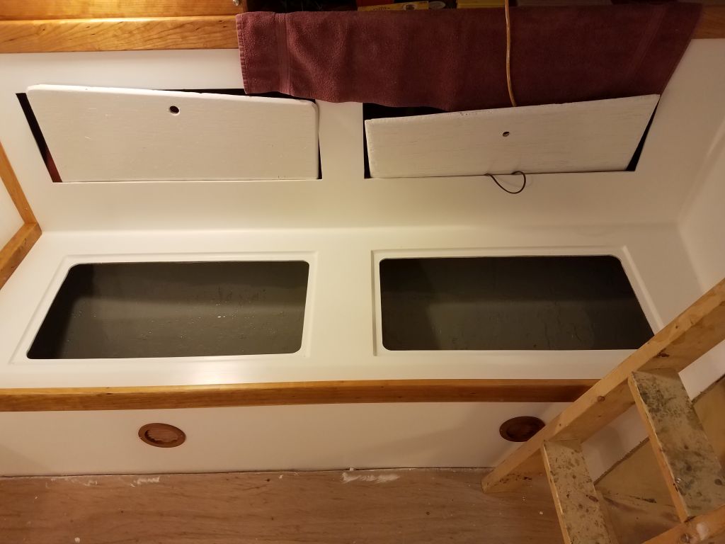
Earlier in the week, I’d pre-primed the new epoxy securing the cleats around the water tank, so now I could proceed with final preparations and painting inside both settee lockers, port and starboard.

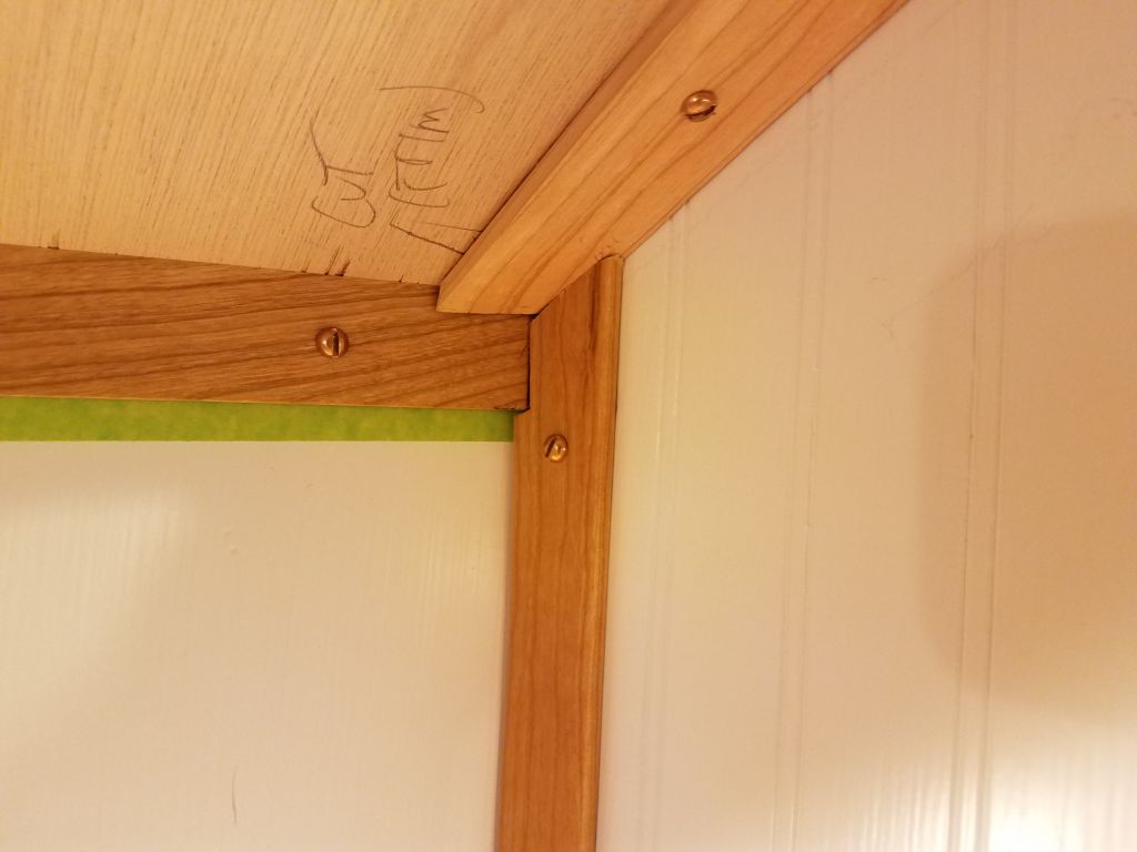
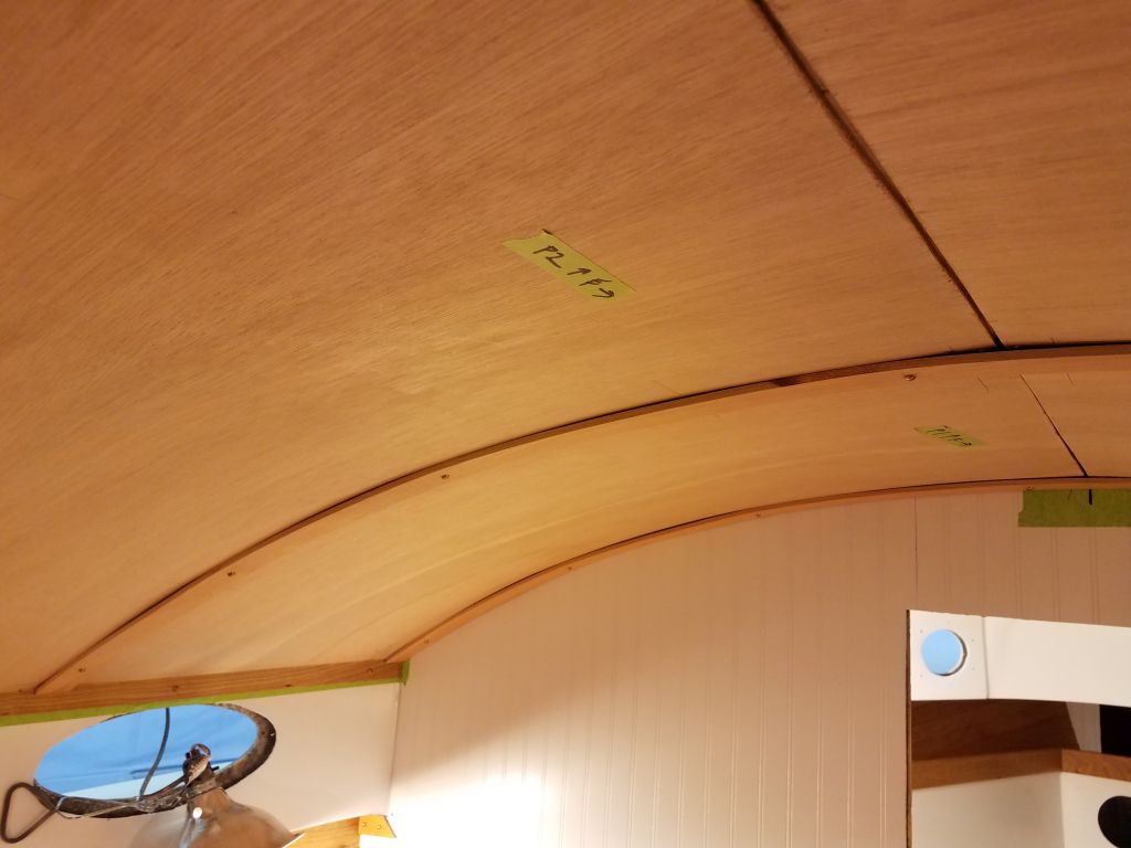
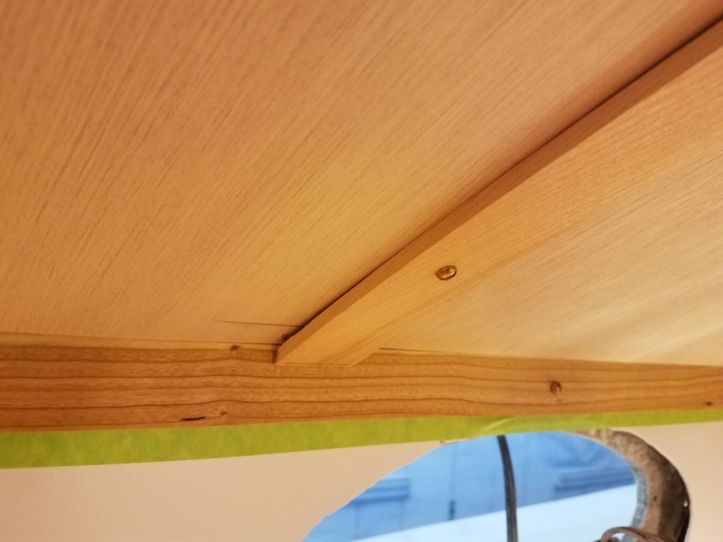
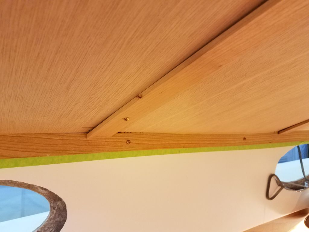
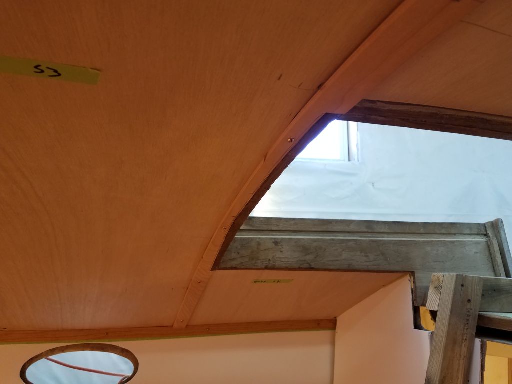
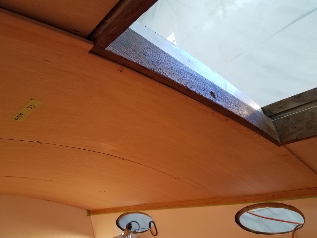
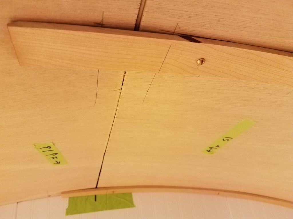
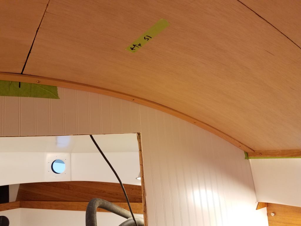
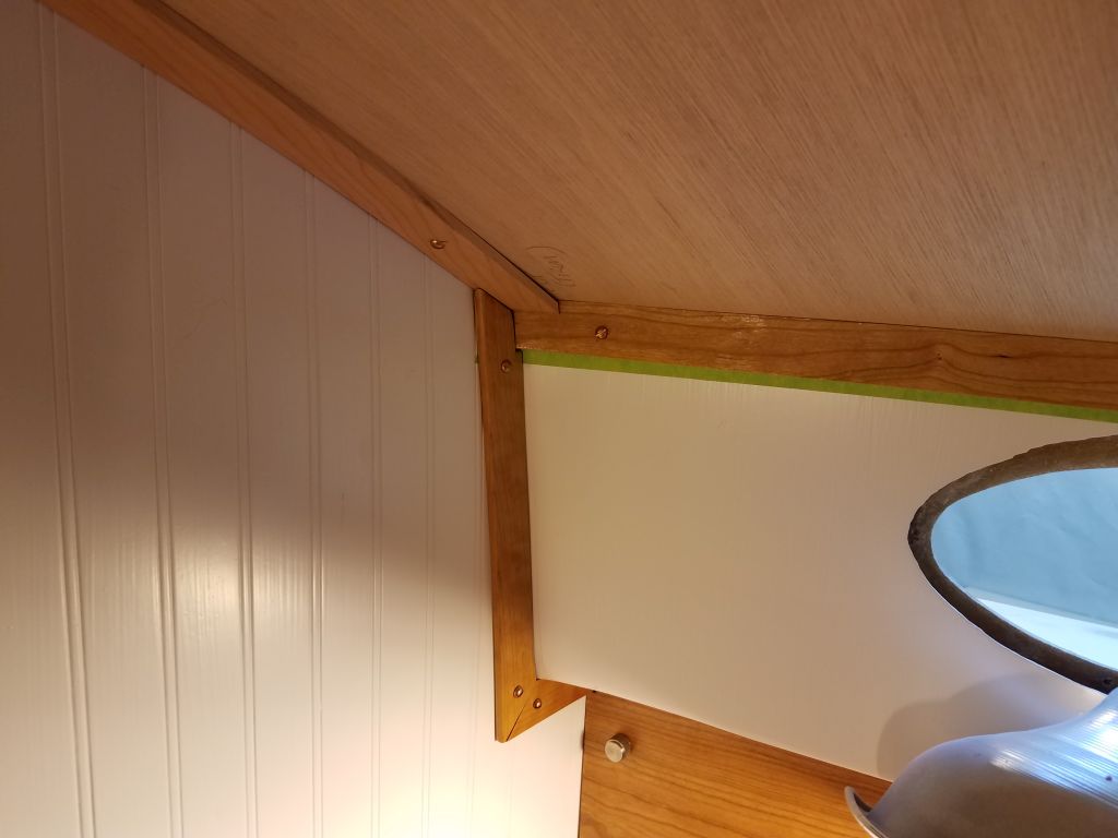
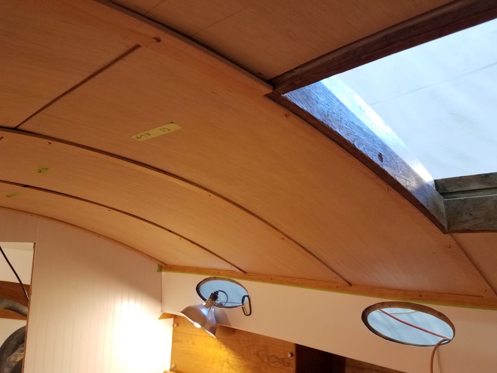
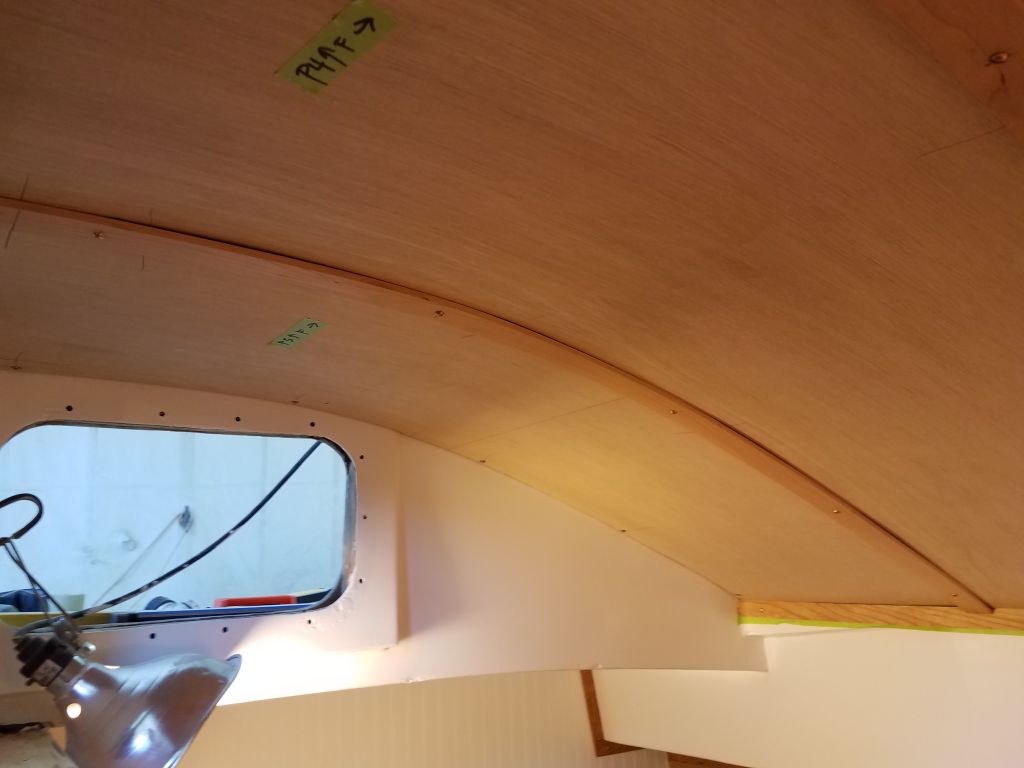
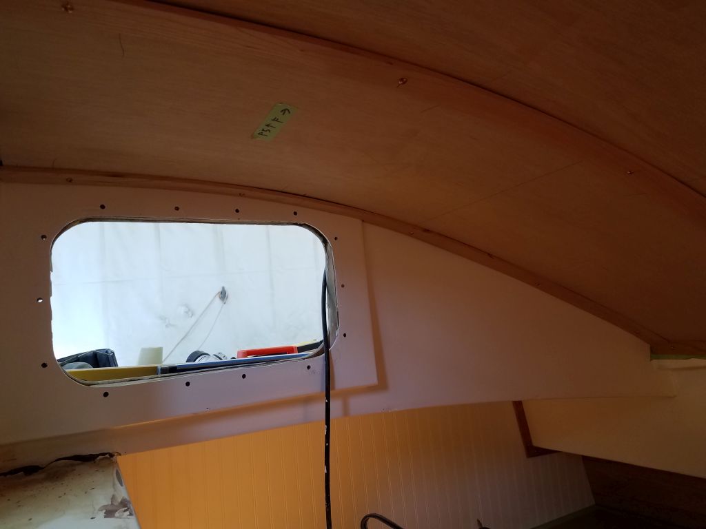
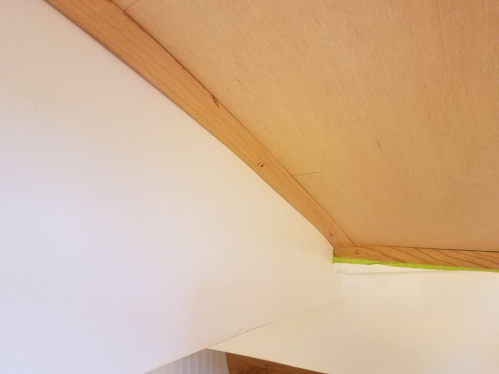
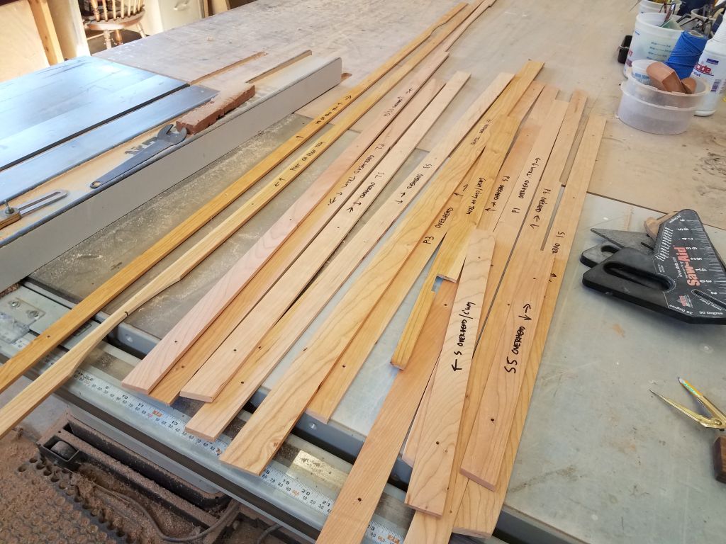
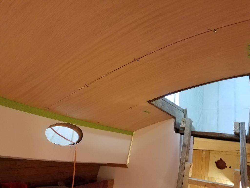
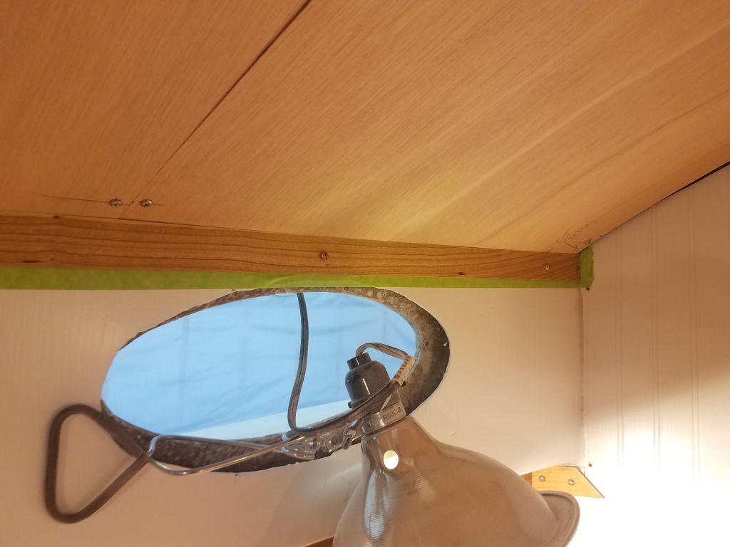
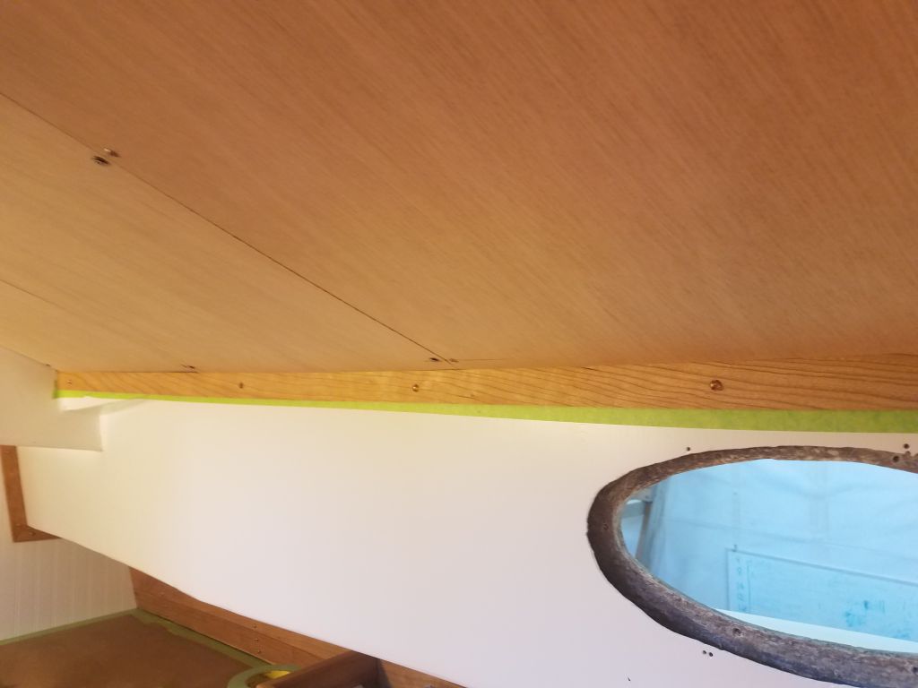
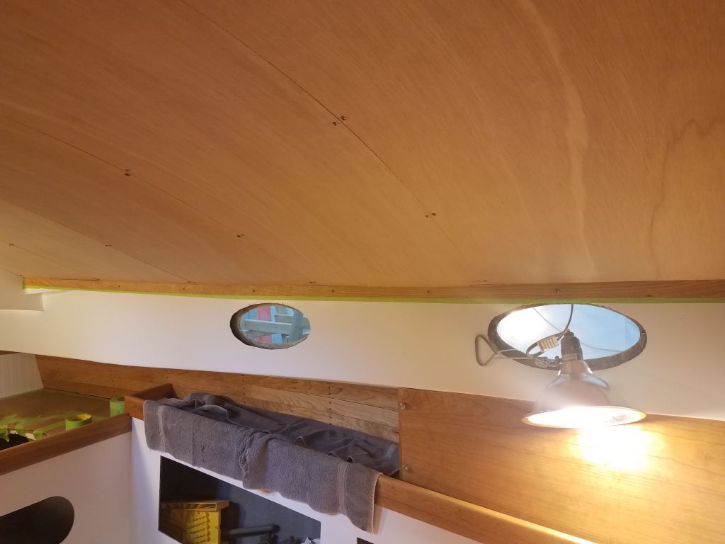
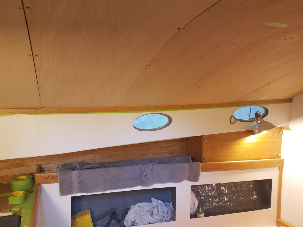
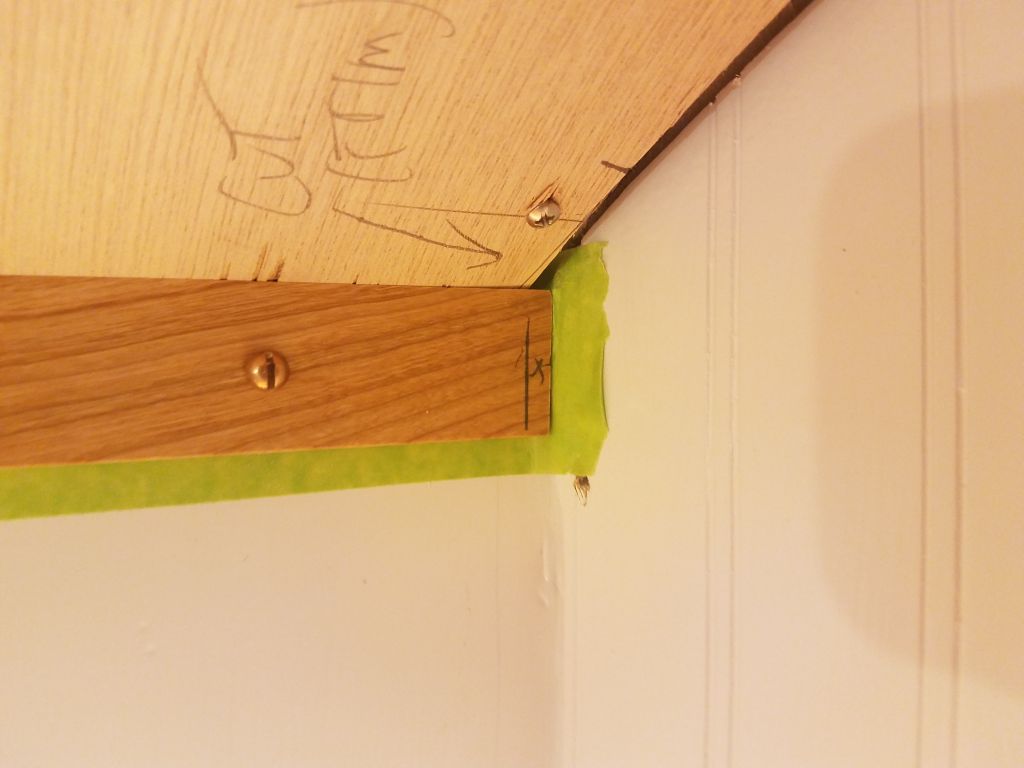
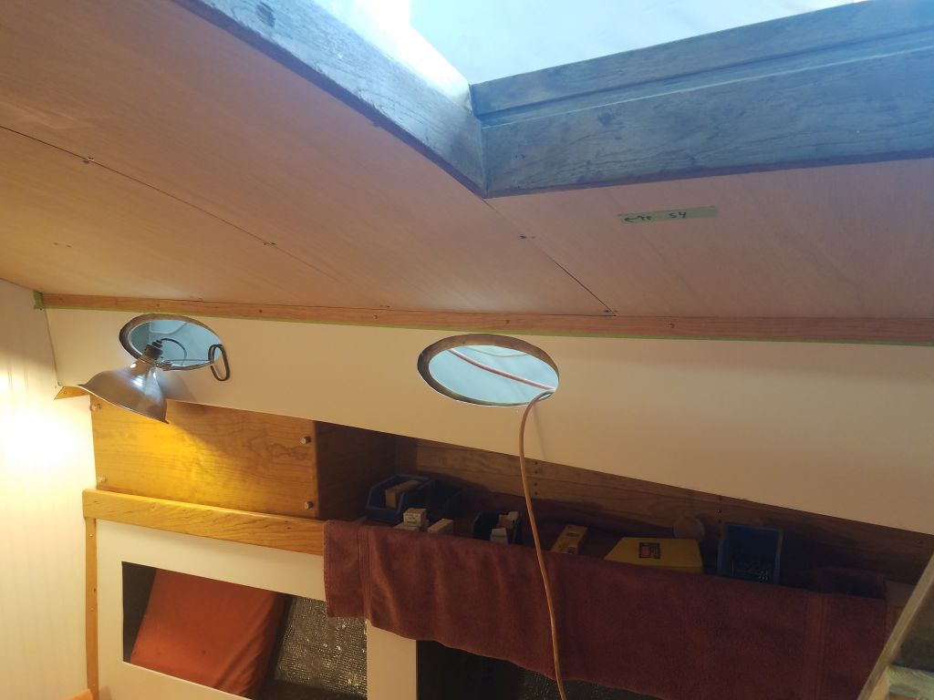
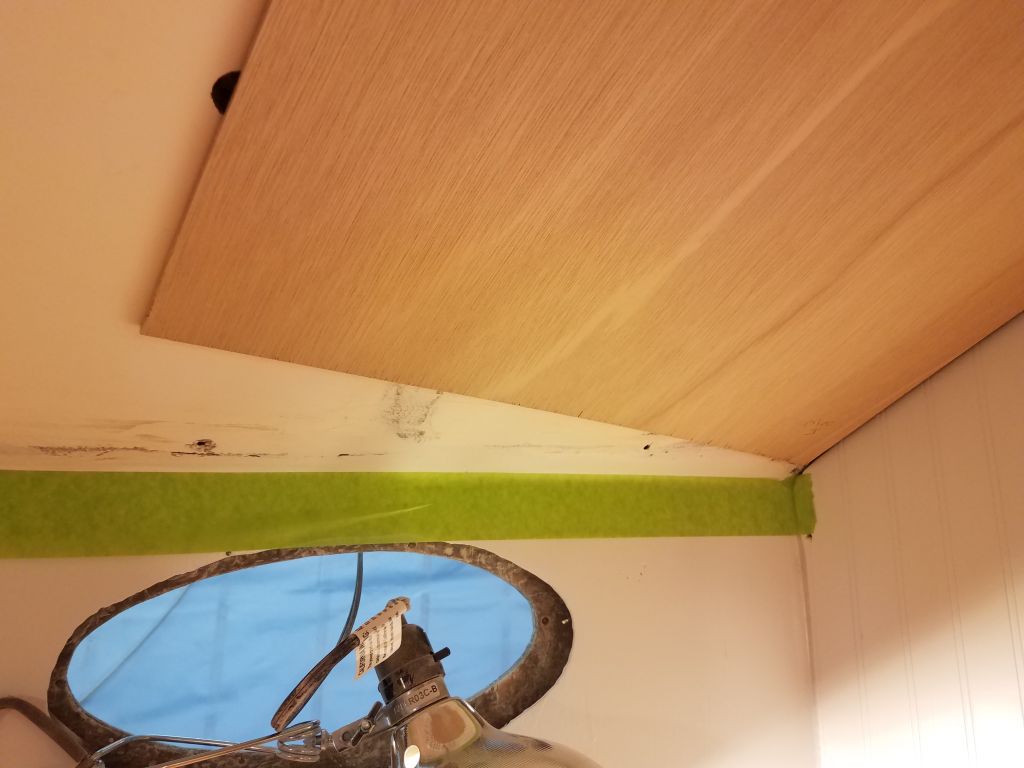
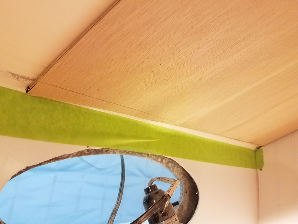
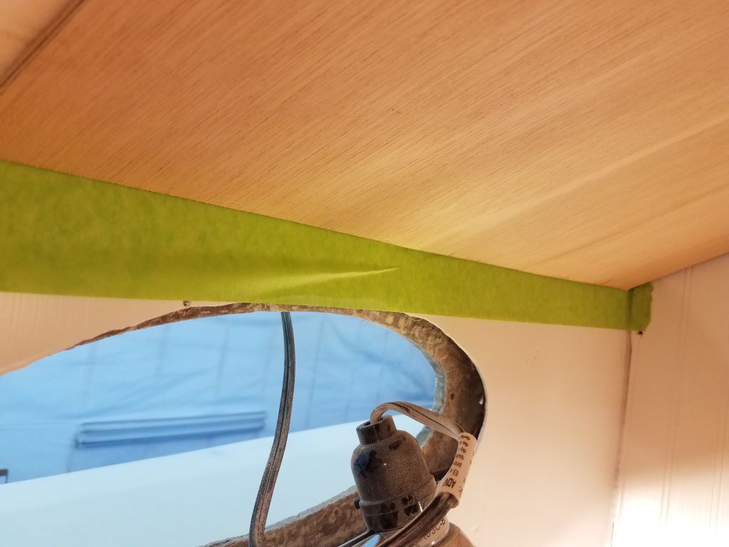
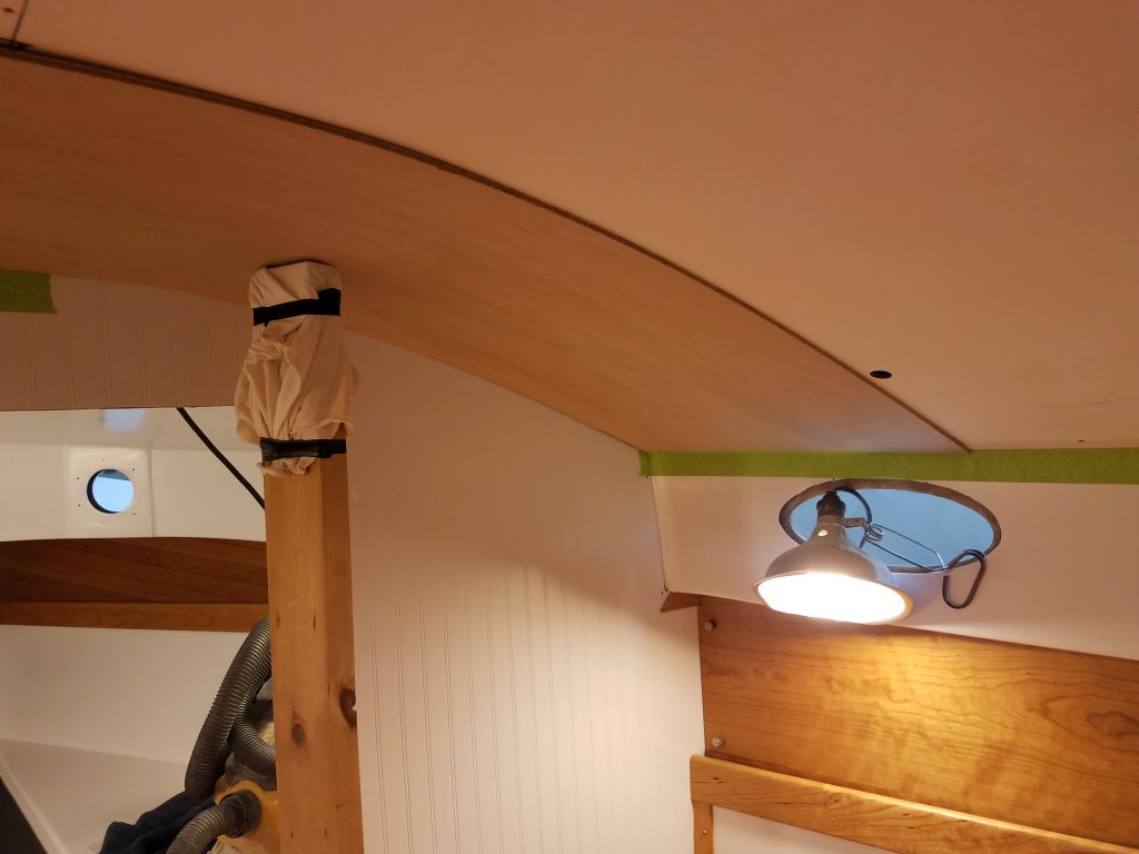
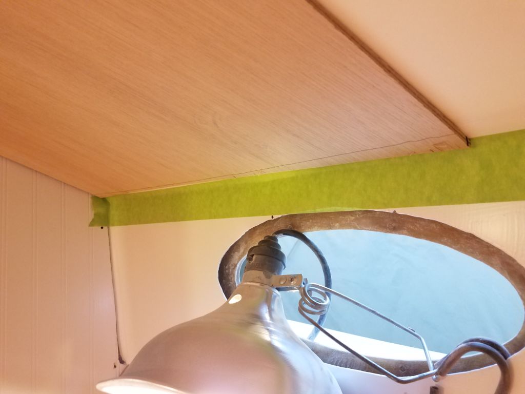
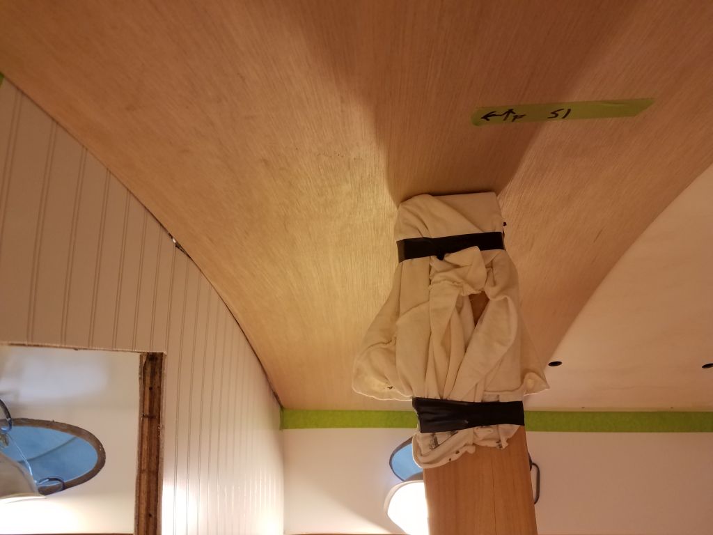
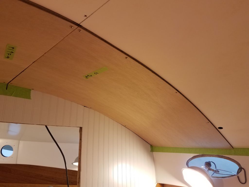
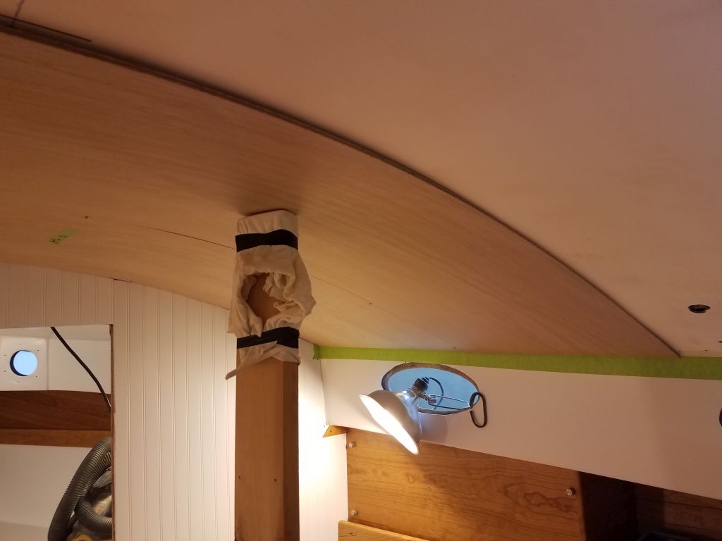
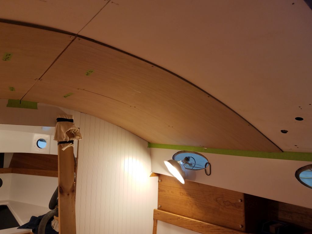
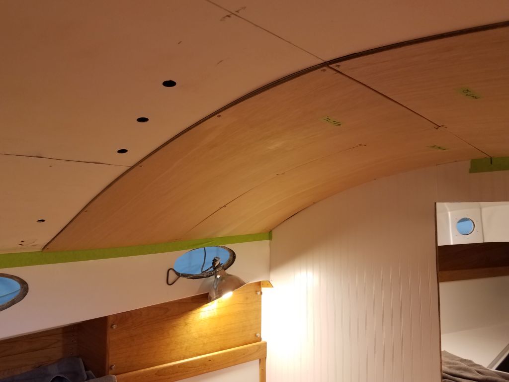
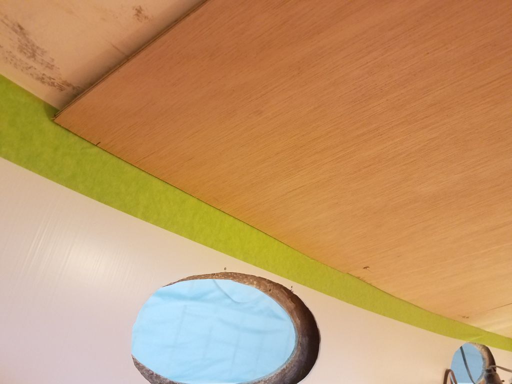
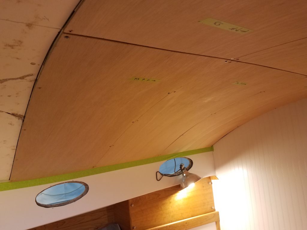
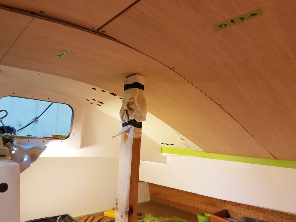
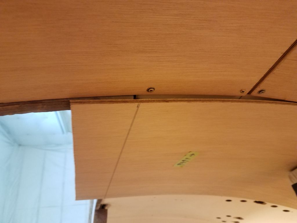
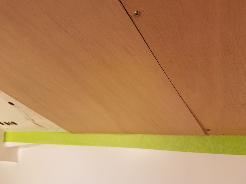
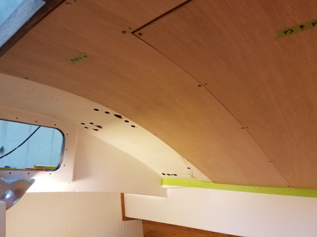
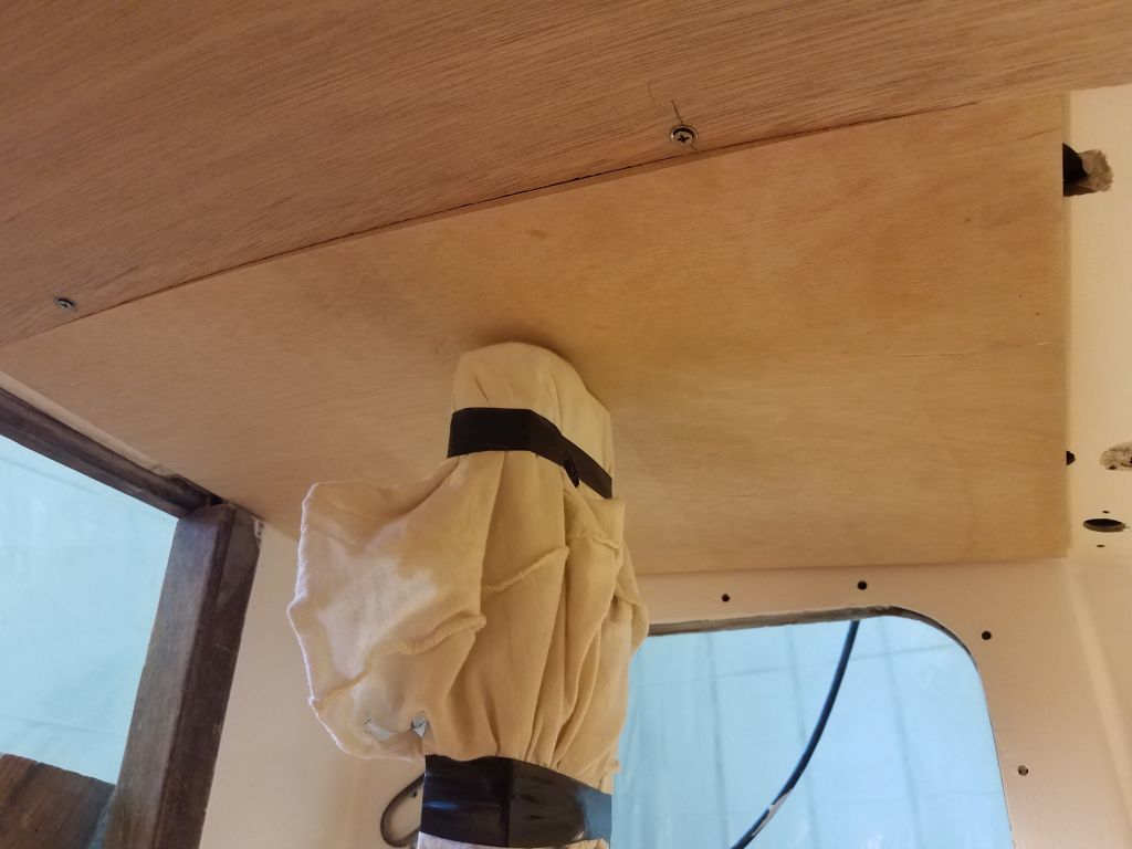
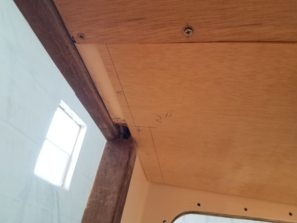
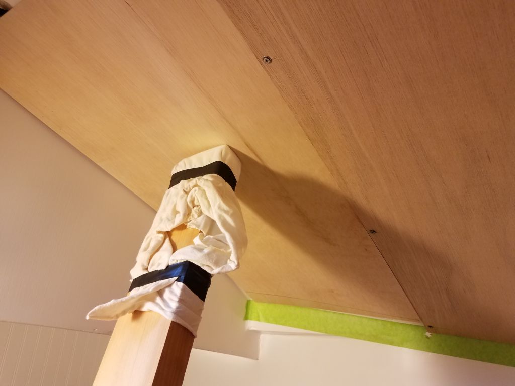
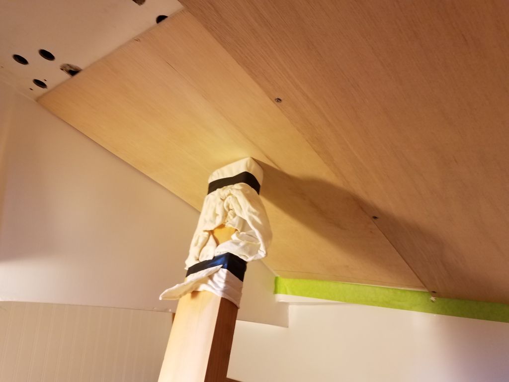
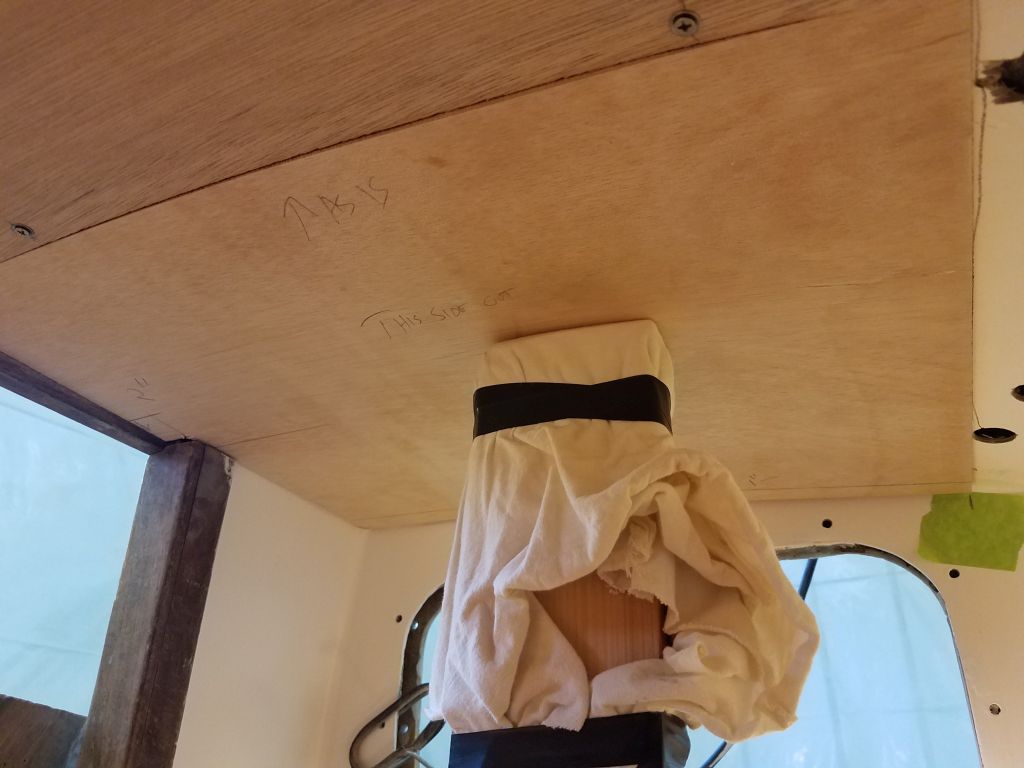
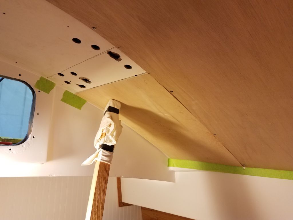
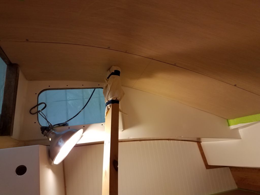
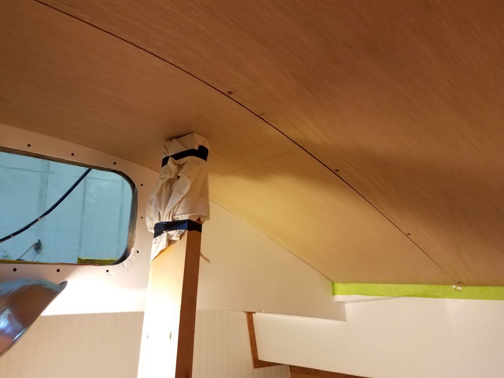
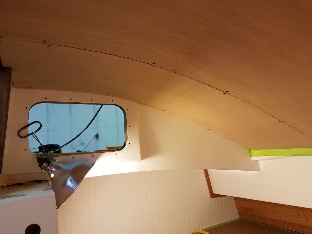
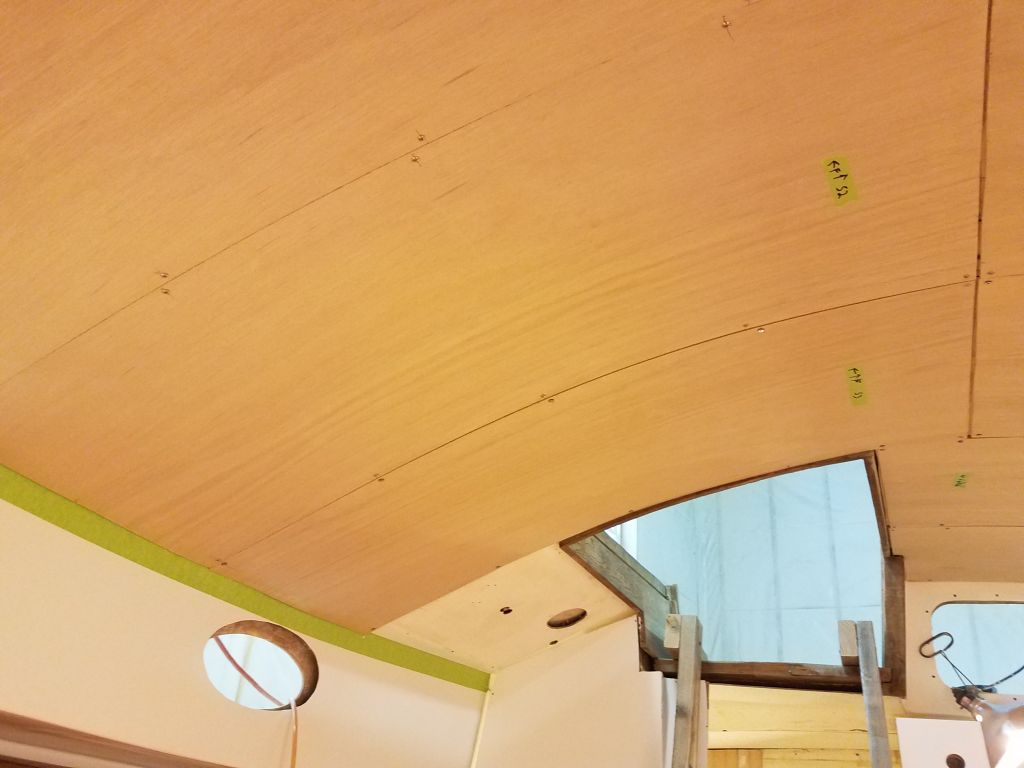
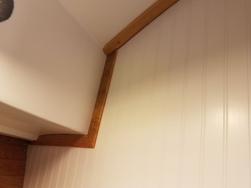
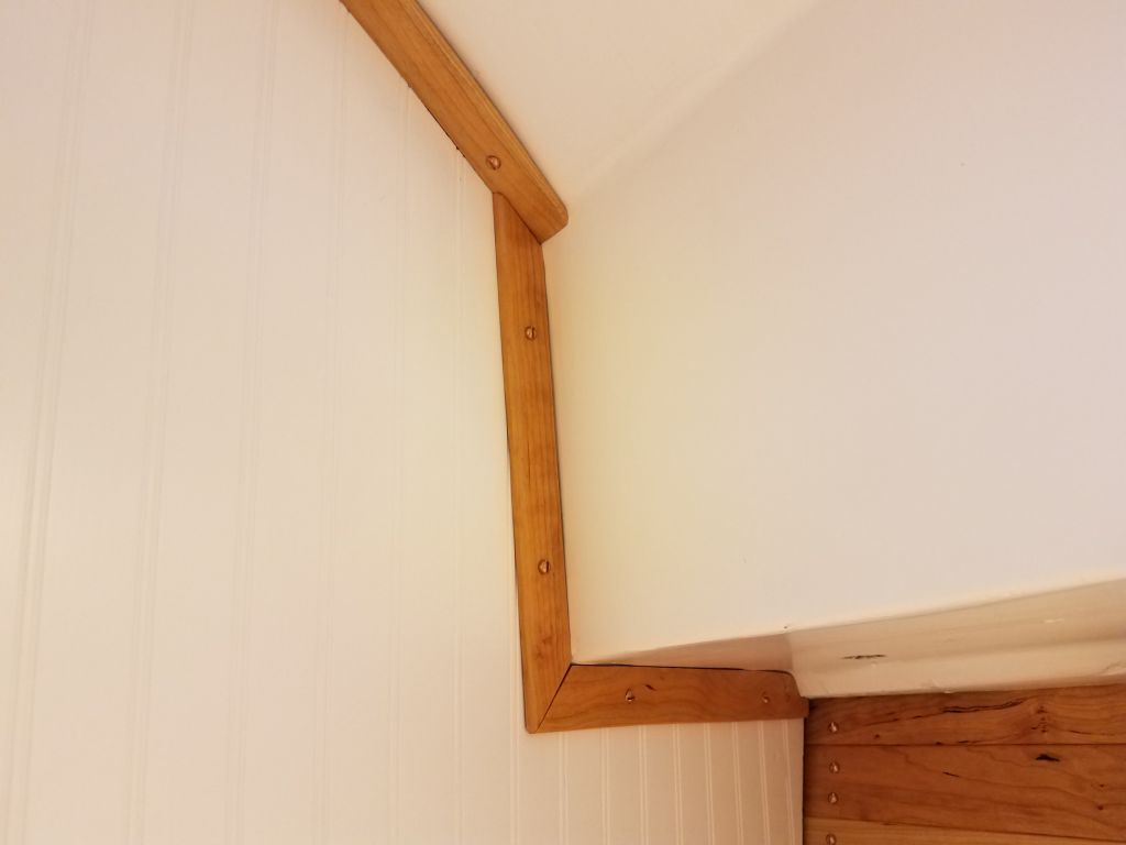
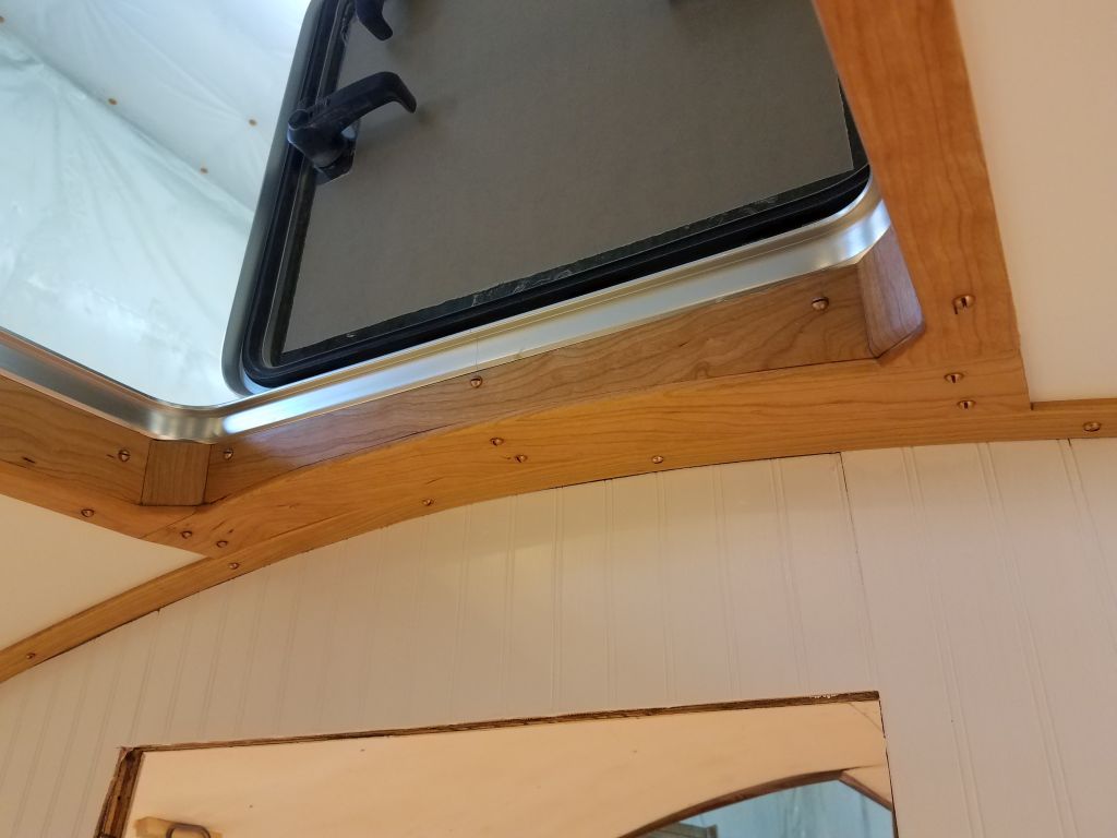
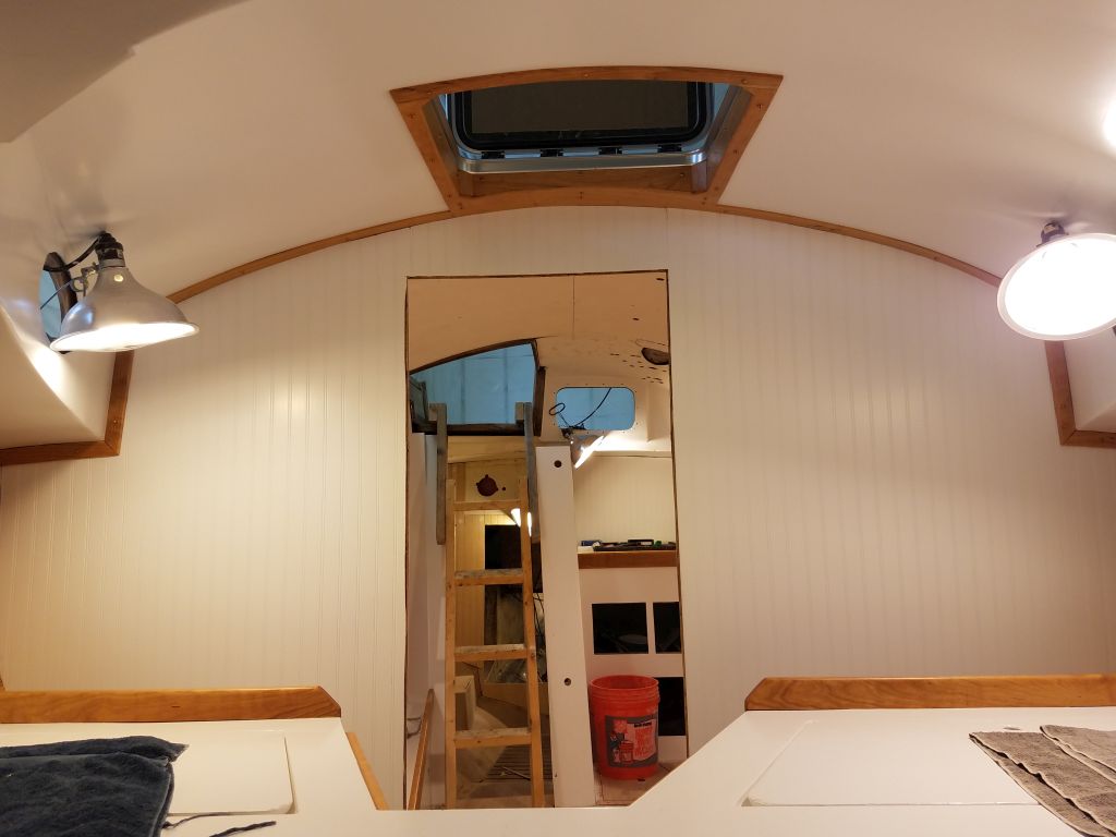
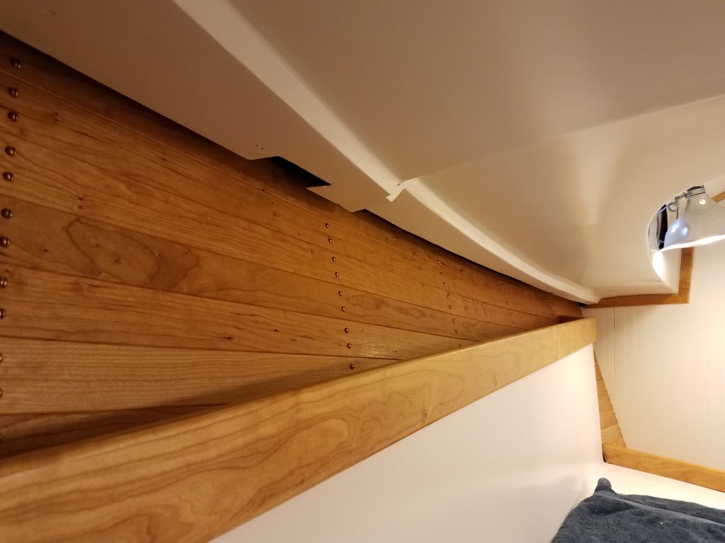
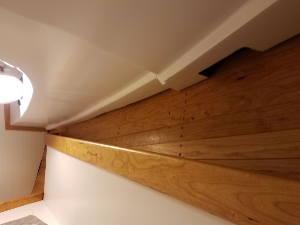
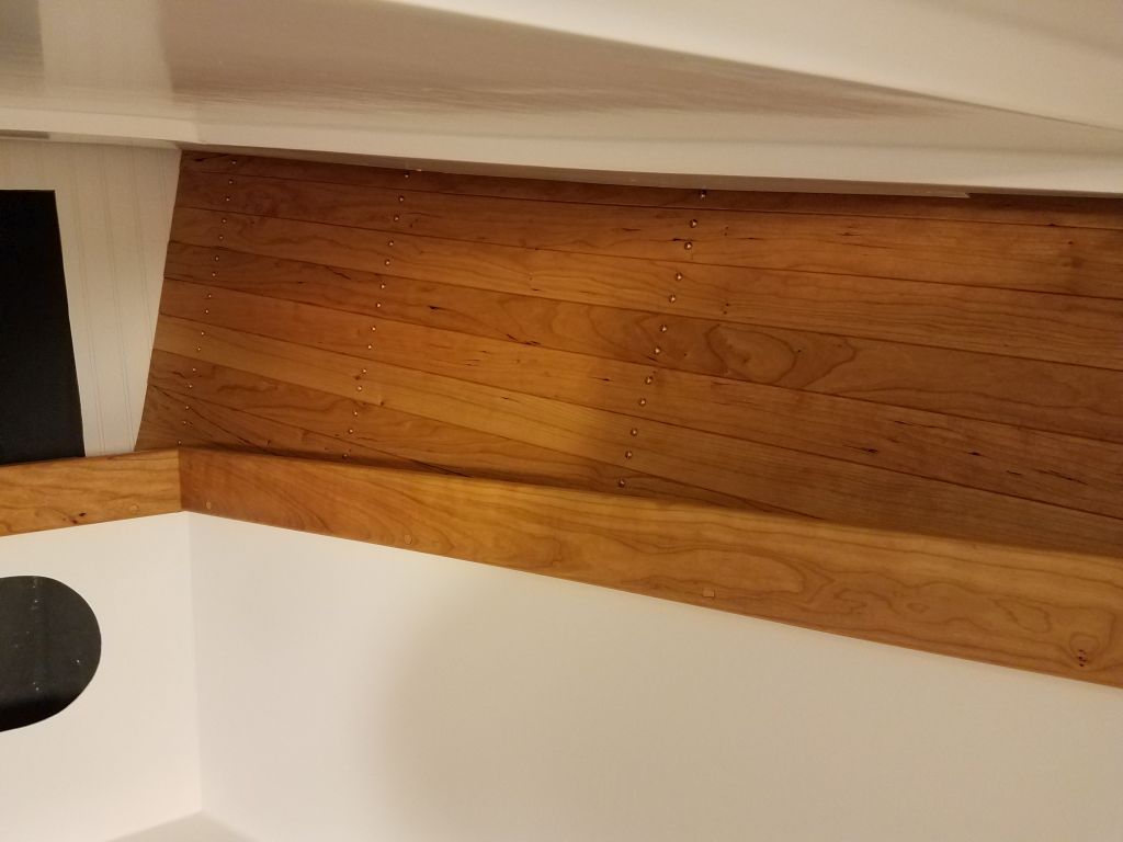
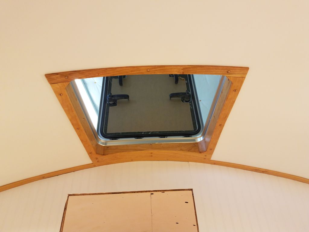
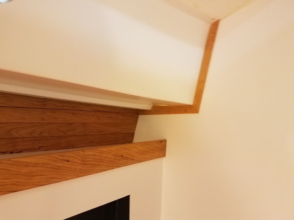
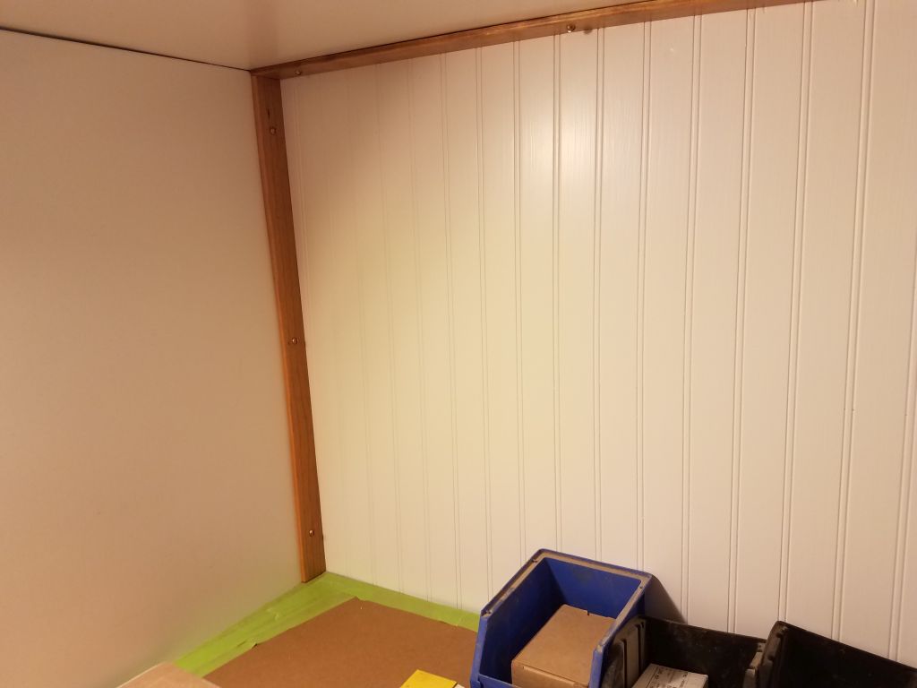
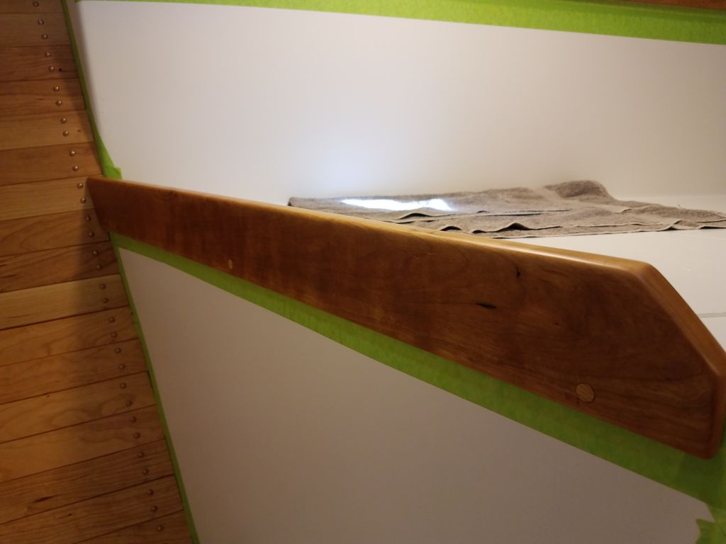
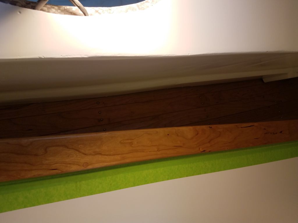
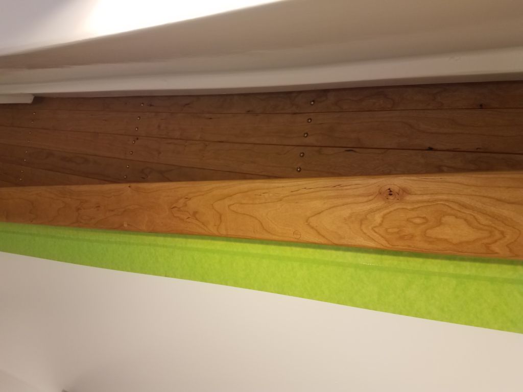
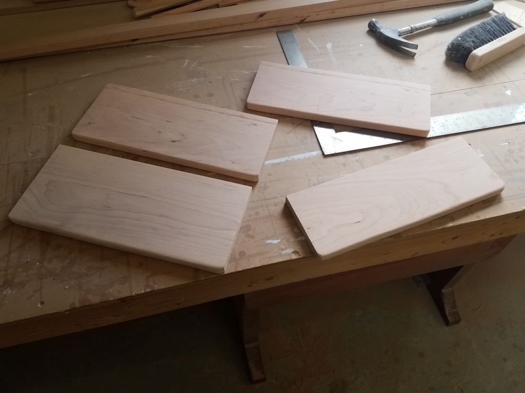
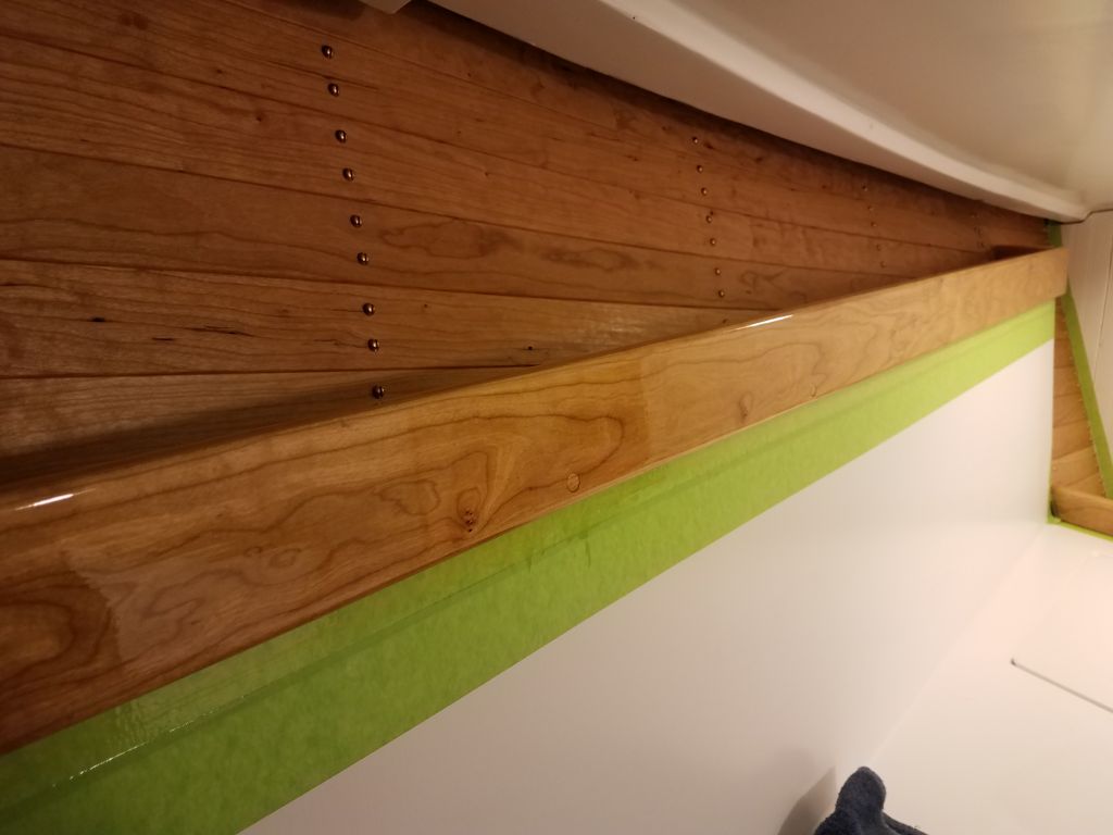
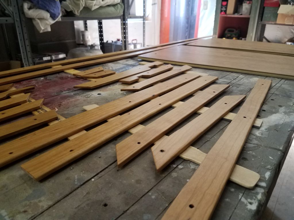
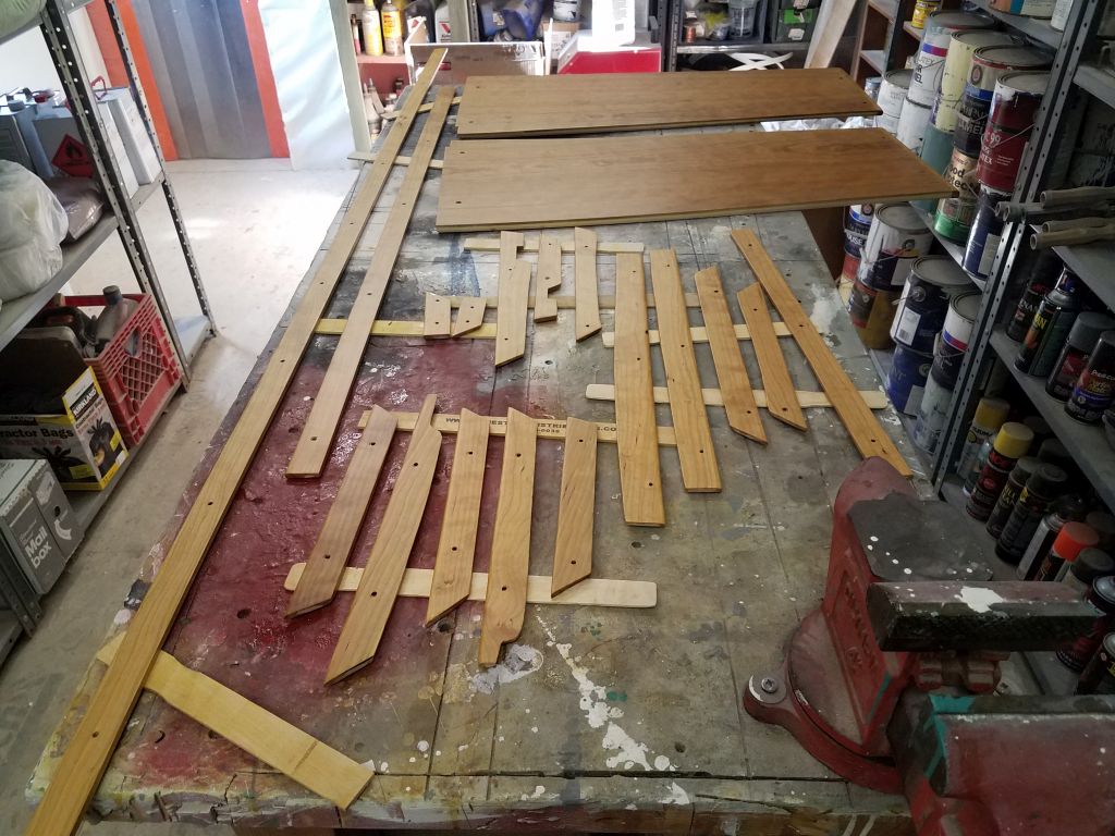
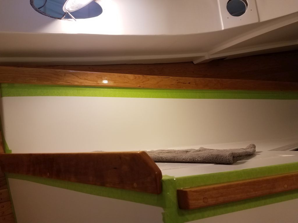
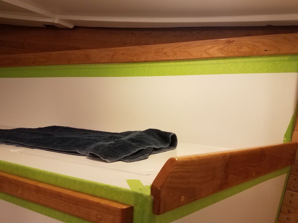
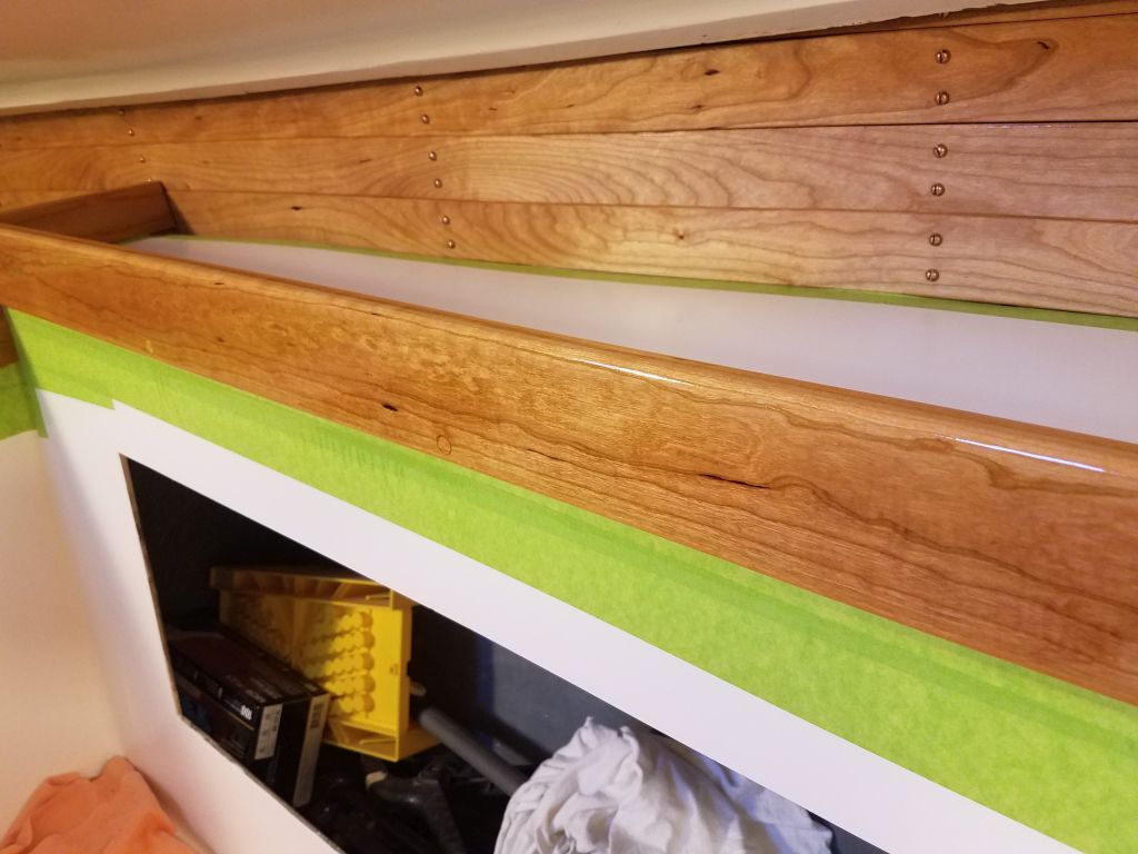
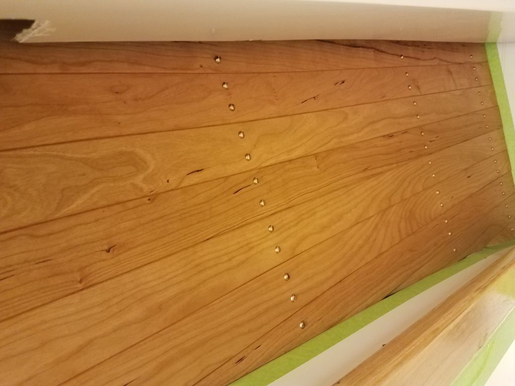
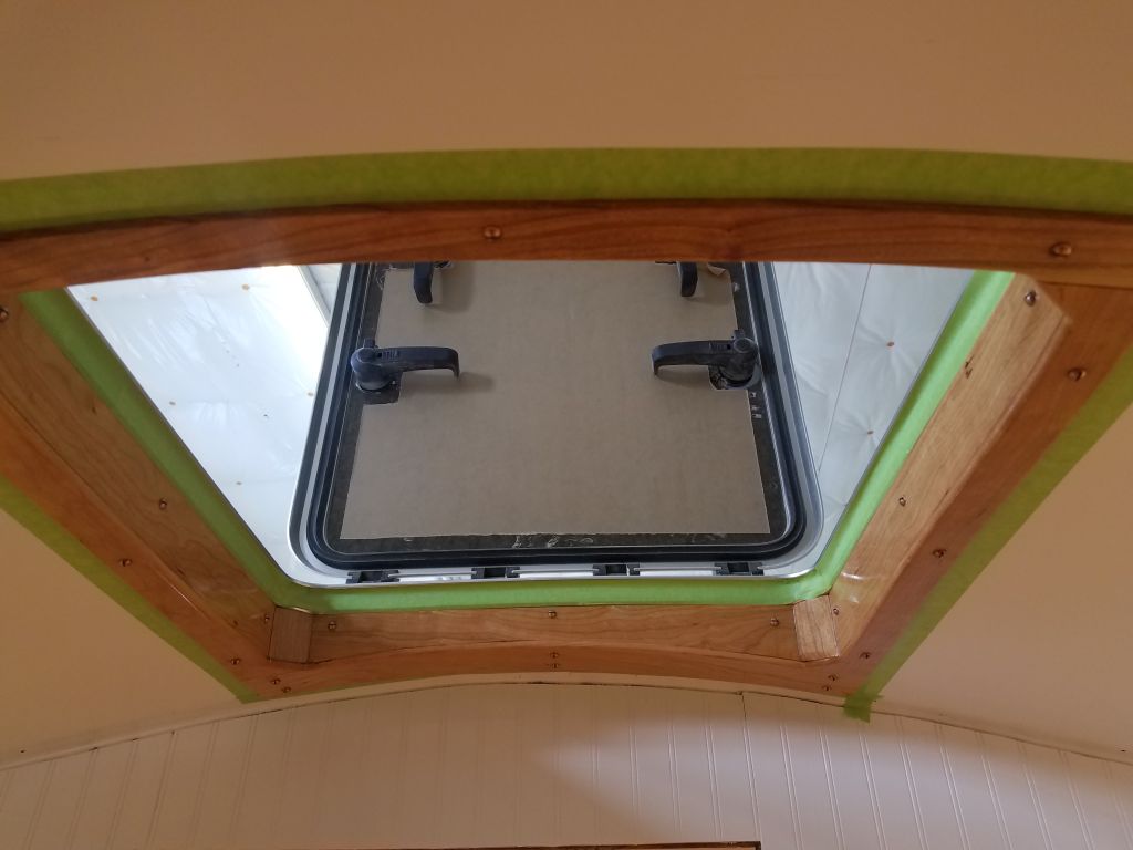
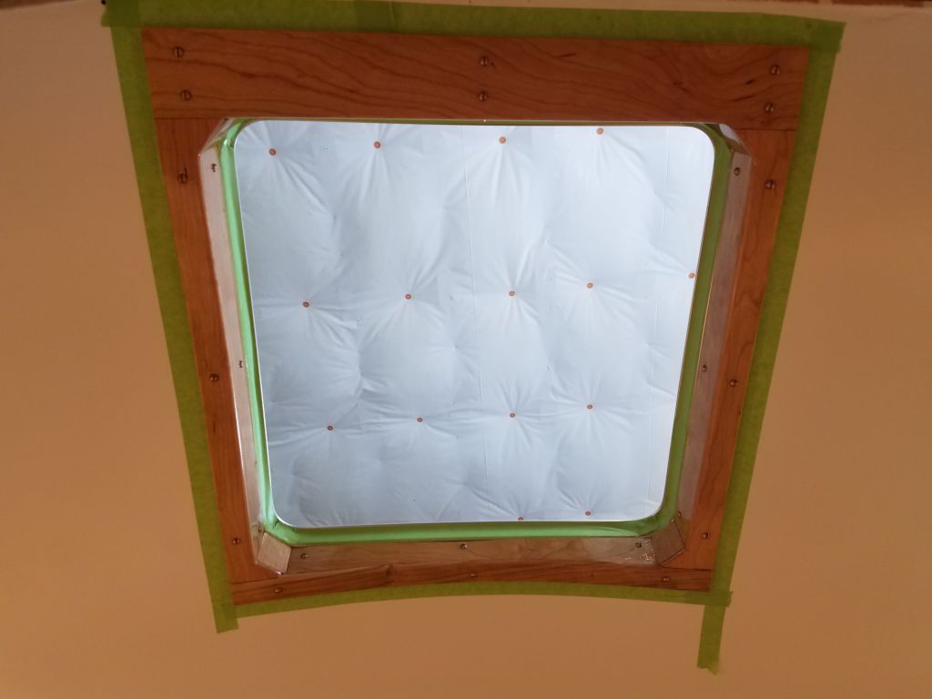
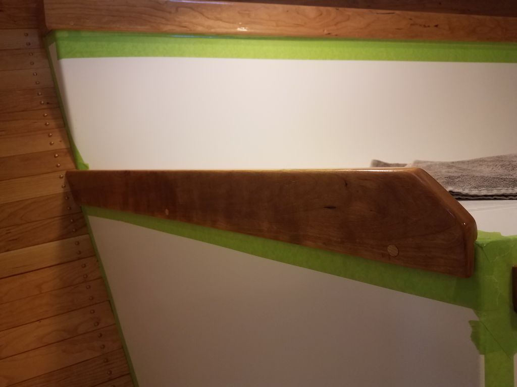
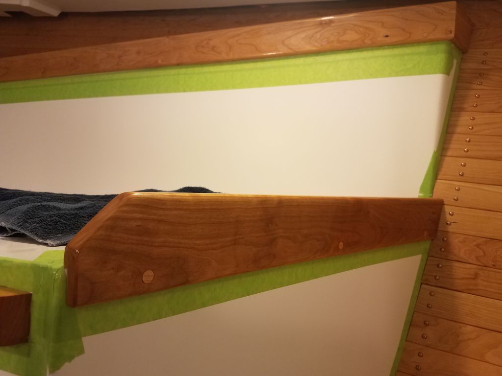
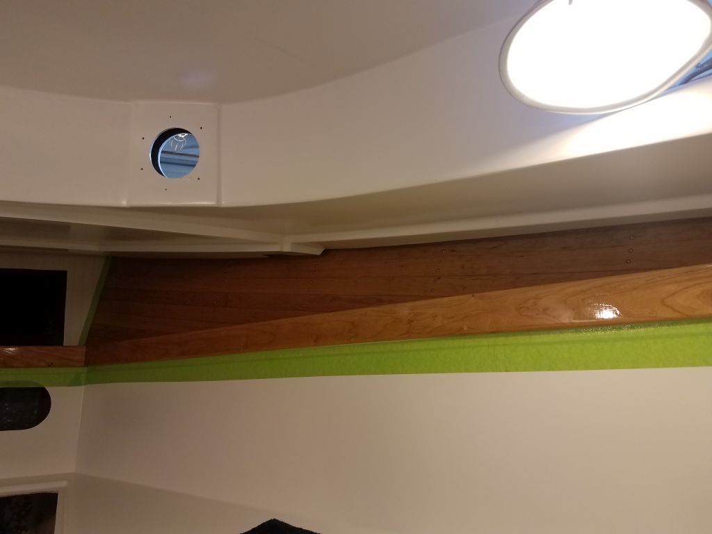
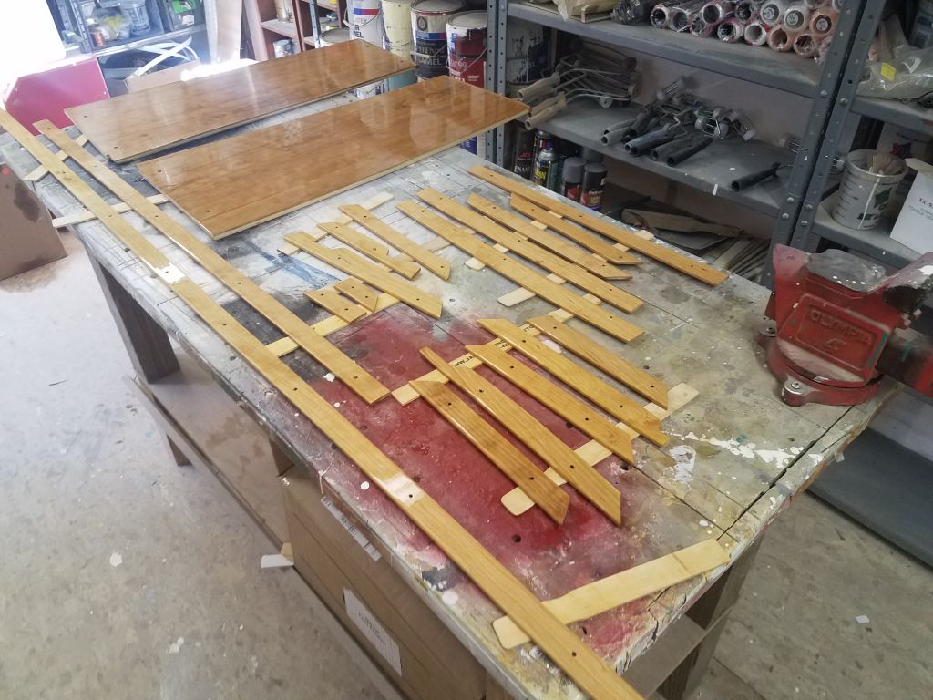
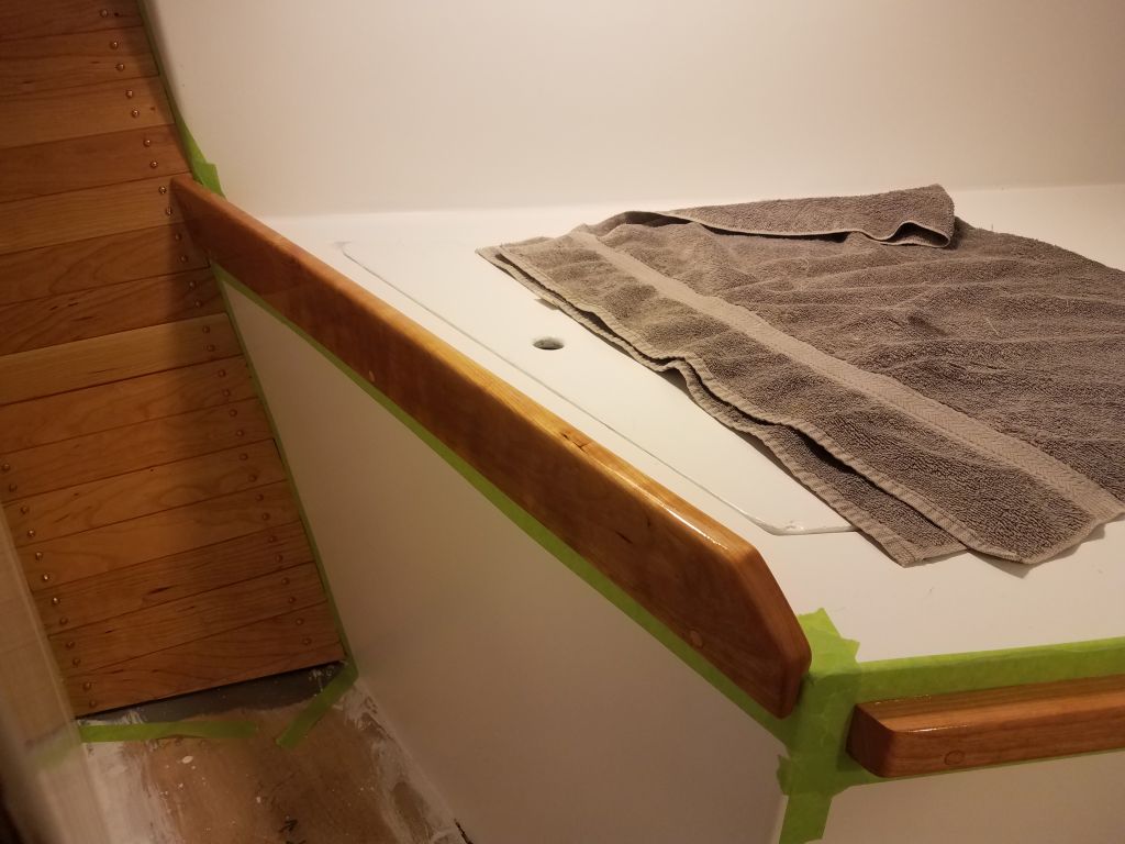
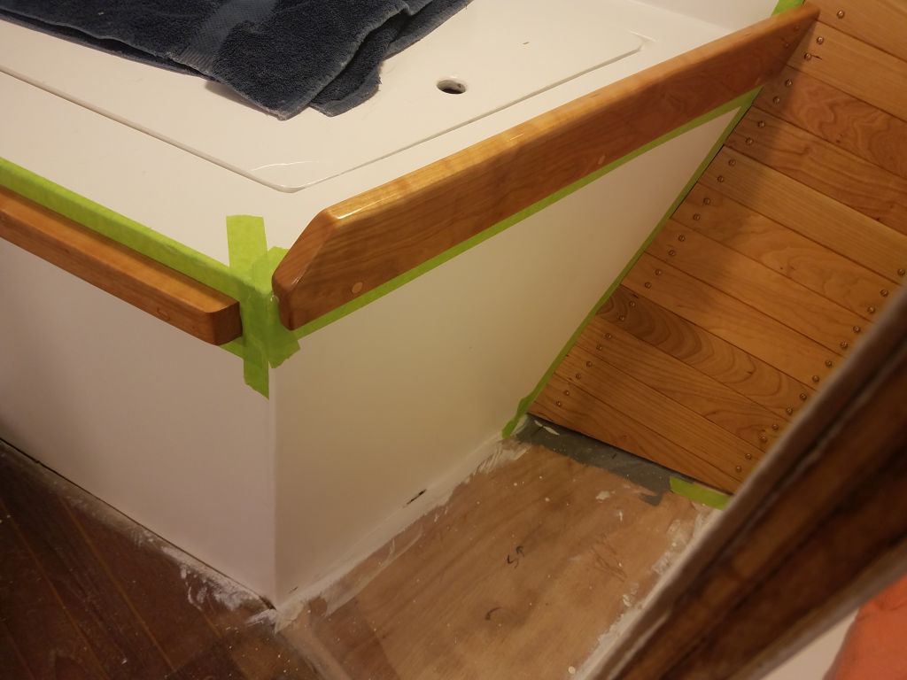
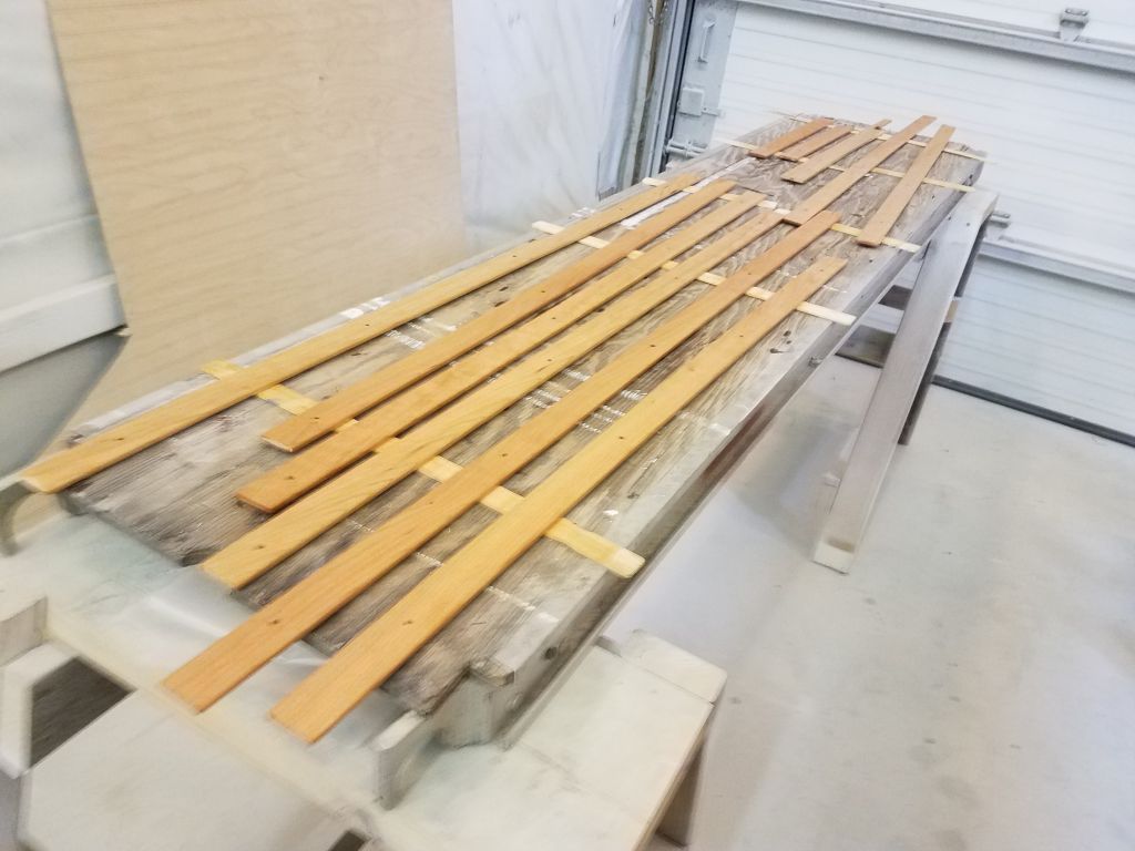
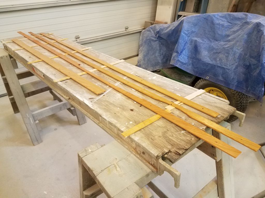
During the remains of the day, I sanded all the new overhead trim pieces as needed, removing layout and tool marks and slightly rounding the exposed edges.  Thus prepared, I applied the first coat of varnish to all sides of all the pieces of trim.

Total time billed on this job today:  8 hours

0600 Weather observation:  31°, mainly clear.  Forecast for the day:  Mostly cloudy, 50°

Scupper 122

Thursday

First thing, I installed the holding tank, securing it in place with two of the cleats I’d made and painted earlier.  I didn’t like the cleats I’d prepared as hold-downs for the top edges of the tank–in the final analysis they didn’t really do the job as I’d hoped–so I made some new, larger ones and set them aside to paint before installation.

With my new stack of milled trim lumber at the ready, I got to work on the overhead trim, starting randomly at the port forward side.  These trims would cover the edges of the plywood panels, and also the screws holding the panels in place, and I planned to run them from each side up to the centerline, where I’d install a longitudinal trim strip across the center seams of the panels.    Keeping the transverse trims only half-width made installation more straightforward, since I could run them overlong at the centerline rather than having to cut and fit an exact length to both sides at once.

With a piece of trim cut to generous, rough length, I scribed the angles where it met the cabin trunk (or, more specifically, the trim I’d installed there), and with a satisfactory fit I fastened it in place with bronze trim screws.  I let it overhang the centerline for now.  This piece of trim also required a slight scribe and cut where it met the vertical bulkhead, since the bulkhead had a bit of a burble in it at this top edge.

The way the two pieces of overhead trim came together caused me to rethink my original plan for integrating the existing (but temporarily-removed) vertical bulkhead trim beneath.  I’d first thought I would trim the new trims to fit around the existing piece, but this just didn’t make any sense, so instead I re-cut the top edge of the “old” trim to fit into the new situation above.

Moving aft on the port side, I cut and installed the second and third pieces of transverse trim, each of which required a compound cut on the outboard ends; as before, I let the inboard end run past the centerline for now, awaiting later trimming to length.  Note that any gaps between the new trim and the plywood indicate where the panel screws are located beneath; I purposely avoided over-tightening the screws for the dry fit, but in the final installation, these screws would be flush, and allow the trim to fit tightly along its length in each case.

The next piece of trim coincided with the forward end of the companionway opening, and also signaled a visual transition between the symmetrical forward portion of the overhead and the two distinct sections of the aft portion.   It would also serve as an end point for the longitudinal centerline trim, as the two panels required aft of this point on the port side would actually pass by the centerline before ending at the off-center companionway hatch.  Therefore, I decided to make this a single piece spanning the entire width of the overhead, and incorporating the companionway opening.

Because the forward edge of the opening was not straight nor square to the rest of the trim, I couldn’t let a regular piece of trim just butt against the forward edge; this would have been nice, but instead I had to make a relief cut to allow the trim to fit.  With a specific length required from side-to-side, and compound cuts at both ends, I chose to make a two-piece plywood template of the trim, using pattern plywood cut to 1-1/2″ wide, same as the trim.    This way, with a few reference marks on the overhead, I could more easily determine the end cuts, the cutout around the companionway, and the final length, after which I transferred the shape to a piece of the cherry and cut out the piece accordingly.

Before continuing with the starboard side trim, I used a piece of 2″ wide stock intended for the longitudinal centerline to mark the ends of the three pieces of port trim where I’d need to cut them; then, I removed the port trim so I could repeat the installation steps with the three forward sections of trim on the starboard side, including changing the cut at the top of the bulkhead trim in the corner.  Then, I marked the new pieces of trim at the centerline as well.

The port after section above the galley required three pieces of trim:  two transverse arcs, plus a wider piece at the companionway edge, which I scribed to fit the shape of the space as needed.  The forward of the two transverse trims was straightforward to install, much as the similar sections forward had been, though this one passed by the centerline and would ultimately end with a butt against the companionway trim; I made a reference mark there for later cutting.

The aftermost piece, against the bulkhead, required another plywood template to fit, as it required a relief cut around the molded flat where the large opening port fit, plus the end cuts to fit properly in the defined space.

Finally, I cut and fit two short pieces of trim as needed to complete the small starboard section of overhead, and re-cut the vertical bulkhead trim to fit the new configuration.

At the two forward deadlight openings in the main cabin, I used the fiberglass inner trim rings to mark each of the edge trims for a relief cut that would be required in order to reinstall the trim rings.  Later, after I’d removed all the trim, I made these cuts.

Now, I removed all the trim pieces, and then the overhead panels themselves, setting all aside for final preparations, varnish, and painting.

Total time billed on this job today:   8.25 hours

0600 Weather observation:  20°, clear.   Forecast for the day:  Sunny, 48°

Scupper 121

Wednesday

First thing, I finished up the last little piece of the overhead paneling, starting with a rough template made from measurements I’d recorded the day before, and cut from pattern plywood.  With the template temporarily secured with one screw (the deadman didn’t fit in the aft corner), I used straightedges to mark the actual shape of the space on the template, and then transferred this to the final 6mm plywood.

I’d get back to the overhead presently, but for the moment one of the day’s priorities was to complete the preparations in the head and holding tank space, so that I could finish up the holding tank installation later in the week.  I now had the additional plumbing fittings that I needed on hand, so I installed them on the tank while the tank was still loose, which made the job easier.  Space and hose run constraints required the use of elbows for both inlet (aft, or to the right in the photo) and outlet, and these fittings always seem to present installation challenges since they require quite a bit of “spinning space” to thread in.  The discharge side would later be split into two sections:  One leg leading to a deck pumpout fitting; the other leg to the overboard tank pumpout for those times it was legal.  (That bronze fitting near the bottom of the tank is acting as a wedge to hold the tank in place, as the weight of the bronze fittings on the top of the tank made it want to tip out of the space on its own.)

To secure the tank (just temporarily for now), I milled a pair of hardwood cleats and secured them to the bulkheads on either side, basically pinning the tank in place between the cleats and the hull.  I also milled, but did not yet install, additional cleats to secure the top edge of the tank and prevent any up-and-down movement.  With the cleats cut and fit, I could then remove them, and the tank itself, and, after final preparations, painted out the space in and around the tank, the last impediment to final installation.

With that crucial step behind me, I returned to the overhead.  After much thought throughout the panels’ installation, I’d decided to cut and install all the overhead trim now while all the panels were still in place, so that once complete I could remove all the trim and overhead sections for final finishing (varnish on the trim, paint on the panels), and to leave the cabin overhead exposed for upcoming hardware installations later in the project as needed.

I started with some trim at the outboard edges of the overhead, to cover the ends of the panels where they met the cabin trunk and at the same time add a nice bit of wood trim to break up what would, in the final appearance, be a lot of white surface.  I had two pieces of 1-1/4″ trim available for this task, and, after milling an angle on one edge of the trim to match the overhead camber, I cut and fit these pieces in place at the top edge of the cabin trunk, securing them with my bronze trim screws.  At the ends, I marked where the existing (but temporarily removed) bulkhead trim would pass, so I could later cut the new overhead trim accordingly.

At the forward (at least) deadlight locations, it looked like I’d later need to trim the trim to fit around the inside port trim rings; I’d dig these out of storage and make some marks before I removed the trim for finishing later.

To finish up the overhead trim, I needed to mill a series of 1-1/2″ wide, 1/4″ thick pieces for the task, so after measuring up a basic list of the required pieces, I used some of my last cherry boards to mill the trim, taking the usual several steps to dimension, resaw, and plane to final thickness enough pieces for the job.  This set me up well for next time, but with another commitment I had to depart once the milling work was complete.

Total time billed on this job today:    5.5 hours

0600 Weather observation:  32°, cloudy, snow, another inch or so from overnight.  (Where was all this snow when it was actually wanted?)  Forecast for the day:  Snow showers ending, then cloudy, 42°


Scupper 120

Tuesday

The original main cabin overhead, part of the molded full interior liner, was in atrocious condition, peppered with numerous hardware access holes and a devastatingly bad opening at the aft side above the galley.  There are numerous photos elsewhere in these pages to document the existing condition of the overhead, but now my task was to construct a cosmetic covering to hide the nasty, while still allowing access for future hardware installations and the like.  I chose 1/4″ (6mm) marine plywood for the task, which I’d paint to match the rest of the cabin.

I did some basic figuring to determine how many, and what size, panels I should use; each seam would require trim to cover the butt joints and fasteners required, so from that perspective fewer sheets would be better.  But practical considerations and logistics dictated smaller panels, and the companionway opening limited the maximum width to no more than 31″ under any circumstance.  The companionway hatch itself also formed a sort of natural end point that demanded to be factored into the overall panel (and ultimately the trim) size.

In the end, I decided to break the largest part of the overhead–between the companionway hatch and the main bulkhead–into three sections per side, or six pieces.  Then, the after portions of the overhead would require a few additional pieces to complete.

These photos date to March 4, 2019, and show some early layout that I’d done at that time.  This basic layout was still valid now, and shows the spaces at work here.

These calculations led me to a panel width of 19-7/8″, and rough lengths of around 52″ to bring me to centerline while allowing extra material for scribing and trimming.  With the first panel cut to size, I fit it in place on the port forward side, next to the bulkhead, and pressed it into the sharp curvature with a deadman cut to length, which held the panel in position so I could work.

The square end of the panel didn’t even come close enough to the shape of the cabin trunk side for me to scribe, so I made a basic measurement, removed the panel, and cut the rough angle required to bring the panel closer to the cabin trunk so I could scribe the final shape of the outboard edge, which I did next and, after cutting the shape (with a bevel to match the angle between overhead and cabin trunk), fit the panel in place for final marking of the centerline of the boat, where the panel would end.

Now I removed the first panel, and repeated the fitting process on the starboard side, though this time I cut the raw angle on the outboard edge first to make it easier to scribe.

After cutting both panels to length for the centerline, I secured each with screws along the edges, directly into the old fiberglass liner.  There was ample space between the liner and the underside of the actual deck for the screws.

I repeated this process with the second set of panels, eventually securing these with screws as well.

The third set of panels had to butt against the existing companionway opening trim on the starboard side, and this dictated the final width of both panels in this pair–just a bit narrower than the first two sets.  The forward trim of the companionway wasn’t square or entirely straight, but I didn’t try to fit the panel exactly since the edge would be trimmed in any case.  After going through all the various fitting steps for both sides of this section, the main, and largest, section of the overhead was complete.

The port after section above the galley required two panels running between the companionway opening (off-center to starboard) and the edge of the cabin trunk.  The general size of these panels fit in and coordinated with that of the three panels in the main section, which was one reason I’d chosen the widths I did in the first place.

The first section in the galley was straightforward enough.

The final piece here required some additional fitting, since it had to fit around the molded area surrounding the large port in the aft side of the cabin, as well as some cuts around the companionway itself.  For this, I used some pattern plywood to mark and fit the various edges first, after which I transferred the shapes to the actual plywood for the overhead.  I mistakenly cut the template piece for the outboard side shorter than intended, but this was of little matter in the end; I just had to measure between my two template pieces and transfer that measurement accordingly.

After a few minor cutting manipulations to get the final piece to fit properly at some of the fussier corners, particularly the flat area around the opening port, I fit the final panel in place as per all the others.

This left only a small section on the starboard side, which I’d finish up next time.

Total time billed on this job today:    8 hours

0600 Weather observation:  32°, cloudy, about 4-5″ of snow down after yesterday.  Forecast for the day: Mainly cloudy, 37°

Scupper 119

Monday

With the current round of varnish work complete, I spent the first part of the day removing all the masking tape.  Afterwards, I reinstalled all the small trim pieces, which I’d removed for varnishing.

To complete the cuts on the side rails for the new companionway ladder, I took one of the rails up into the boat and set it in place, using a piece of 3/8″ plywood to hold the base off the existing sole an appropriate amount (1/4″ for the finished sole, plus 1/8″).  With the piece properly positioned, I used a straightedge to mark the height and angle at the top, where it met the companionway threshold.

Back at the saw, I clamped both side pieces together and made the top cut.  Then, at the top I marked a rounded corner reminiscent of the original piece and cut and sanded the curve smooth before rounding the edges of the new cuts and sanding everything smooth once more.  The finished height of the new piece is slightly different than the original because the new cabin sole, with its thicker substrate and cherry veneer atop, would be slightly higher than the original sole, which was thinner to begin with, even with its finished veneer.

Now I could assemble the ladder permanently.   After solvent-washing the bonding areas as needed, I began by spreading waterproof glue on the bottom slots, and installing the lower step, aligning the back edge properly with the rabbet in the side rails and clamping it in place.  For the moment, I left off the back panel, since its absence made it easier to install, align, and glue the treads.  One step at a time, I glued and clamped in the treads, and once all four were in place, I inserted the back panel in the rabbets.  Because I didn’t want this panel permanently installed yet (I planned to paint it white to offset the treads and match the original appearance), I masked off the edge that sat in the rabbet, but the panel was important to ensure proper alignment of the whole unit while the glue set up.

Leaving the companionway assembly to cure, I turned to the forward storage compartment beneath the v-berth.  Because it was handy to stand in this area when working on the trim and varnish in this area, I’d purposely left it unfinished for the duration, but with the bulk of the work now complete up there, it was time to wrap up the work in the locker.  After vacuuming and solvent-washing the whole space, including the far reaches at the aft end beneath the molded liner and cabin sole above, I installed a series of heavy wire tie mounts along the top edges of the space on both sides.  I’d use these later for supporting windlass cabling and whatever else was required, but I had to install them now since the adhesive used with the system didn’t stick well to paint.

While I waited for that adhesive to cure, I installed the six round cherry vents in the settee and v-berth locker sides, where I’d cut holes previously.  I’d already finished these vents with varnish, and now installed them with small screws.

I’d had the new holding and water tanks on hand for a couple weeks, and with the recent flurry of trim and finishing work out of the way for now, it was time to get these tanks installed.  To that end, I’d ordered various fittings that I planned (hoped) to use for each tank, but when I set the holding tank in place on the platform I’d built, I quickly discovered that my original fittings configuration wasn’t going to work because of a lack of clearance; in my mind’s eye, there was more room above the tank than in reality, and my plan for the tank discharge wasn’t going to fit as I’d hoped.

This didn’t pose a big problem; it just meant that I’d have to await further installation steps with this tank till I could get different fittings that would work at the discharge (i.e. forward, or left in this photo) end of the tank, since it was easier to spin on the various fittings while I could still move the tank around.  I ordered the required fittings and would continue the tank installation as soon as they arrived.

The smallish water tank planned for the space near the galley was an easy fit in the locker, and the fittings I’d planned for this tank worked as intended, so I moved on with final installation.  I’d originally planned to have the tank sit near the aft end of the after compartment beneath the settee, but the tank seemed to nestle perfectly into a spot a bit further forward, beneath the divider between the locker lids, and this also worked better because it improved vertical clearance for the tank inlet and vent, and also left the aft end of the space more open for better usage and access to a yet-to-be-installed foot pump near the galley.

To secure the tank, I cut cleats from leftover teak stock on hand, and after preparations epoxied the cleats in place around the tank base.  These cleats, along with the inside of the settee itself, would hold the tank in place in four directions, but to hold the tank firmly down against the hull I ordered a strap that I’d install later to secure the tank completely.

Now that the day was getting on, it was time to paint the forward locker; I’d left this task till late since the paint fumes from this paint are strong.

The companionway had been clamped for several hours now, and the glue was dry, so I unclamped the assembly and removed the back panel, then drilled for and installed four screws into each tread (two per side) to add strength to the whole thing.  Afterwards, I bunged all the screw holes.

Total time billed on this job today:   8.25 hours

0600 Weather observation:  32°, cloudy, light snow showers.  Forecast for the day:  Snow, 3-5″predicted, 34°


Scupper 118

Saturday

Because of unforeseen circumstances during the week that forced my absence from the shop, I’d fallen behind where I’d hoped to be, especially with the interior varnish, so I planned to make up some time and progress over the weekend.  With 4-5 good coats of gloss base varnish on all the trim, all that remained was a final coating of satin varnish to complete the work on the trim installed so far.

After the usual sanding and cleanup, I applied the satin finish.  Later, once the varnish had a chance to dry, I took photos of the results, which looked good, though I planned a careful final inspection before deeming the coating complete in these areas.

Now that I had all the basic pieces cut for the companionway ladder, I continued work on the new treads, trimming each to its final width (about 1/4″ deeper than the slots in each case, leaving a small overhang) and rounding the exposed outer edges for appearance and smoothness.

I cut the handhold slot in the outboard ladder rail with a drill bit and saw, and rounded the edges with a router before also easing the other exposed edges of the side rails accordingly, then sanded these parts smooth and clean as well, leaving them ready for final trimming (the side rails were still a few inches long at the top awaiting a final fitting) and ladder assembly next time.

Total time billed on this job today:  5 hours

0600 Weather observation:  34°, cloudy, a slushy coating of snow overnight.  Forecast for the day:  Gradual clearing, 50s

Scupper 117

Friday

With another limited day available, I focused first on the interior trim varnish, with another round of sanding to prepare for the fourth coat of gloss base varnish on all areas.

I was ready to commit to the ladder treads on the new companionway ladder, but before making the dado cuts in the side rails to accept the eventual treads, I used some scrap to simulate the tread at the angle I’d chosen, which was 90° to the back edge of the side rails and gave the treads a backwards angle for better grip.  Satisfied with the visuals, I committed and set up the table saw with a 3/4″ dado cutter and, after some testing on scrap to get the depth where I wanted it, carefully made the eight cuts required (four on each side).  

Next, I clamped up the side rails with the plywood back so I could work on the treads.   I selected some boards from which to cut the blanks for the treads, and milled four blanks into slightly over-length and over-width pieces for the task.  The stock itself was a bit thicker than 3/4″ (the thickness of my slots in the side rails), so I planed them all down to the proper dimension to fit snugly.  I used a scrap of the same material to determine the proper length to fit between the rails and in the slots.

Having determined the correct length, I cut all the blanks as needed and fit them in place, clamping up the assembly dry to check the fit and overall appearance of the new ladder.  The treads were still deeper than necessary, which I’d intended so I could  mark and trim them accordingly.  For the moment, I was out of time, but I marked the treads where they extended beyond the sides of the ladder, and would soon trim them and finish up related steps so I could think about assembling the ladder for good.

Total time billed on this job today:  4 hours

0600 Weather observation:  20°, clear.  Forecast for the day:  Increasing clouds, 42°

Scupper 116

Thursday

The various small trim pieces and panel fronts I’d treated with the satin varnish cured well, and to all appearances were complete.

For the remaining trim underway in the boat, I went through the usual processes of sanding, vacuuming, solvent wash, etc. before applying another round of gloss base varnish to all areas.  Unfortunately, this was all I had time for this day.

Total time billed on this job today:  2 hours

0600 Weather observation:  30°, clear,   Forecast for the day:  Sunny and windy, 42°

Scupper 115

Wednesday

I had to divide my time this week, with some unplanned personal obligations requiring my attention, but still very much wanted to keep the varnish work going, so I allotted at least enough time each day to continue the process.  After a morning away, I returned to the shop in the afternoon and, over the course of a few hours, lightly sanded all the ongoing brightwork, then cleaned up as usual and applied another coat of gloss base varnish to all areas, beginning with the ceilings.

Afterwards, I continued with the rest of the interior trim in place.

With five coats of gloss varnish on the small trim parts and locker door panels, this time I switched to the rubbed-effect satin varnish for what could be the final coat of finish.  When wet, as in the photo, it shows as glossy, but would dry to a delicate sheen.

Total time billed on this job today:  4 hours

0600 Weather observation:  32°, light rain and snow mix.   Forecast for the day:  Rain and snow, then all rain and showers, then ending and clearing after noon, high around 50°

Scupper 114

Tuesday

Normally, I’d leave interior varnish work till the end of the day, so I could work in and around and wherever, but since I wanted to be sure to get the base coats underway, and with the whole boat prepared for the purpose before I had to leave unexpectedly the day before, I chose to do the varnish work first thing, to ensure its completion, all the more so because I wasn’t sure how long it would take.

I began with the small trim pieces, electrical locker panel fronts, and the forward hatch frame, all of which had been underway for some time and were using more or less full-strength varnish at this point.  I say more or less because I find that in ambient shop temperatures (usually in the mid-50s), it’s beneficial to add a bit of reducer for flow purposes.

I like to use a wiping tung oil varnish finish for the ceilings, as it’s quick and neat to apply over the large areas with many fasteners, and cures to a satin finish virtually identical to that which I’d ultimately achieve on the other trim with the rubbed-effect satin product I’d finish with.   On the ceilings, I began with the first coat of the wiping varnish on the ceilings before moving on and applying the first coat of varnish to all the installed trim in the boat.  This was really the second coat on the trim, since all of it had already received a sealer coat before installation, but with the new bungs and light sanding, it effectively reverted to coat one for my purposes now.

Knowing that the fresh varnish would ban me from the cabin for the rest of the day, before I started early in the morning I test-fit the plywood panel I’d previously cut for the companionway ladder/doorway assembly, as I planned to work on this down in the shop for the remainder of the day.  I’d sized the panel according to the original ladder assembly, but left it intentionally over-long for final trimming, so now, with the panel in place and set up at the proper angle, I made a few reference marks where the panel passed key parts of the boat since at the moment I wasn’t sure how the original ladder had worked (later I reviewed the photos of the original interior to help work this out).

The original ladder assembly had extended up even with the threshold of the companionway, which was one of the reference points I’d marked on my new panel, so with this and the original ladder as  guides, I eventually chose to trim the top of the panel straight and square about 3/4″ lower than that, leaving room to add solid trim at the top that would incorporate the ladder angle and cover the edge grain of the plywood.

During earlier discussions, the owner had requested a few small, but significant, changes to the ladder, including increasing the angle if possible, as well as providing back-angled treads for increased security.  Because the angle of the basic assembly was required to match that of the adjacent structures in the boat, which, like the original ladder, were sloped at 15°, the only way to practically change the ladder’s final angle was to add in the angle on the side rails of the ladder itself, increasing its width towards the bottom.  We were shooting for an increase to 20°, which had the effect of actually lessening the steepness of the ladder and would make the ascent and especially descent easier going forward.  This was a reasonable compromise between the fixed requirements of the existing structures and the desired ease of ingress and egress, while avoiding the ladder taking up too much space in the process.

To this end, I spent some time laying out the new side rails on some pattern plywood, working within the known constraints of the cherry lumber I planned to use (much earlier, I’d set aside two wide, clear boards for this purpose) and with the desired improvements in the angle.  This ultimately increased the width of the rails (and the depth of the ladder) by 2″ at the bottom, while keeping the original dimension at the top.

With a pattern in hand, I could trim the two side boards to the proper (but still over-length) length and then cut the new angled outer edge with a straightedge and a circular saw.  I cut the angle on the bottom sides of the boards, but left the tops untrimmed for now.

To cover the edges of the plywood back structure, and add strength to the whole assembly in its final construction, I laid out and cut rabbets on the back edges of both side rails, which would allow the 1/2″ plywood to sit flush within.  I trimmed the plywood as needed to keep the ladder’s overall width where it needed to be according to the original ladder.

Now I clamped the new side rails against the original ladder, and, taking some alignment and measurements from the old ladder, transferred the treads’ positions to the new rails.  I also transferred the position of the handle on the outboard side of the ladder, though later I moved the position closer to the edge of the new rail to match the offset of the original, as the new rail was an inch or so taller here now thanks to the improved angle.

With the treads’ basic positions now marked, I wanted to incorporate a new angle to the treads, so that they angled down slightly at their back sides; the old treads had been essentially level, which didn’t lend itself to footing as secure as it might be with an angle to help the foot have somewhere to go.  “Level”, in this case, meant parallel to the bottom of the ladder with its 15° angle, which I marked in a test portion of the board along with a few other options, including one where the new treads would actually be square to the back (straight) side of the ladder.  With the test ladder rail propped up against the bench at its final angle, I checked the layout lines to see how they looked in proper perspective, trying to choose which angle worked best for the new treads.  At the end of the day (figuratively and literally), I was leaning strongly towards the layout that was square to the backs of the rails, and went as far as to lay out the top edges of each tread location at this angle, but since time was out for the day it was a good opportunity to let the idea settle and mull the pros and cons before committing to the cuts required to support the treads in the side rails.

Total time billed on this job today:  8 hours

0600 Weather observation:  20°, clear. Forecast for the day:  Sunny, 47°

Older posts Newer posts