(page 2 of 5)

Danusia 36

< Back to Danusia

Monday

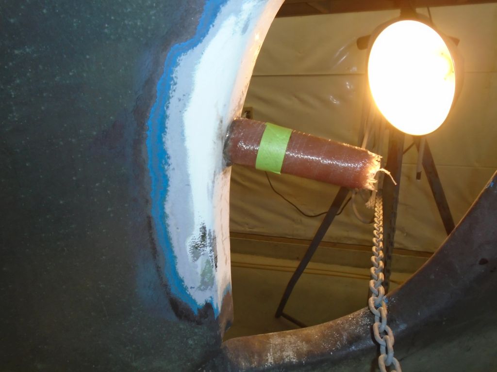
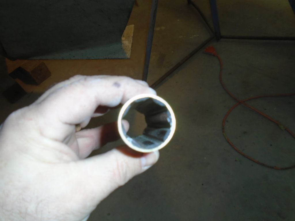
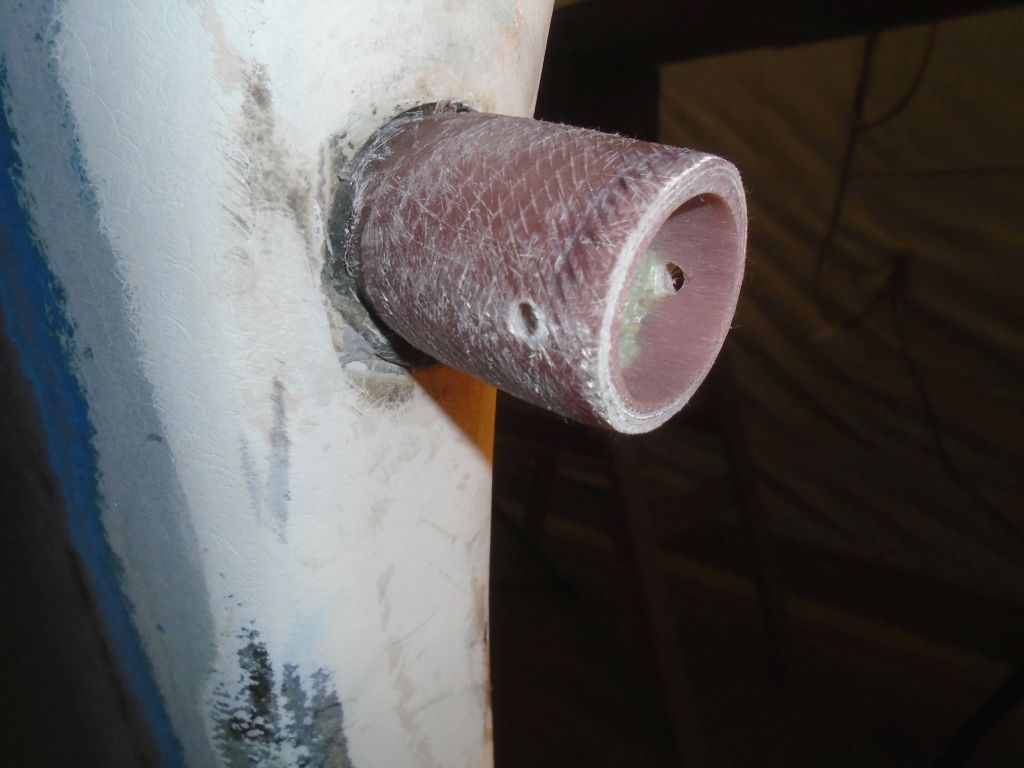
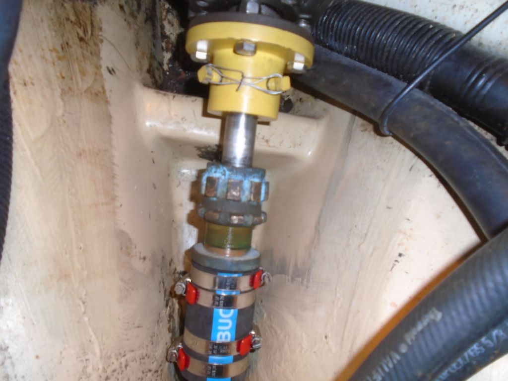
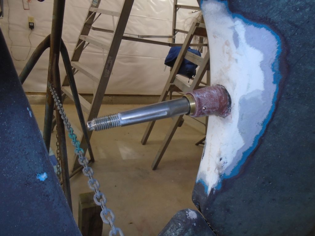
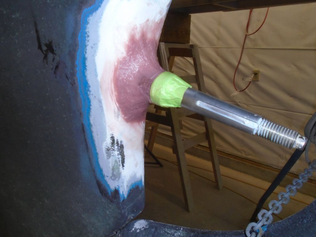
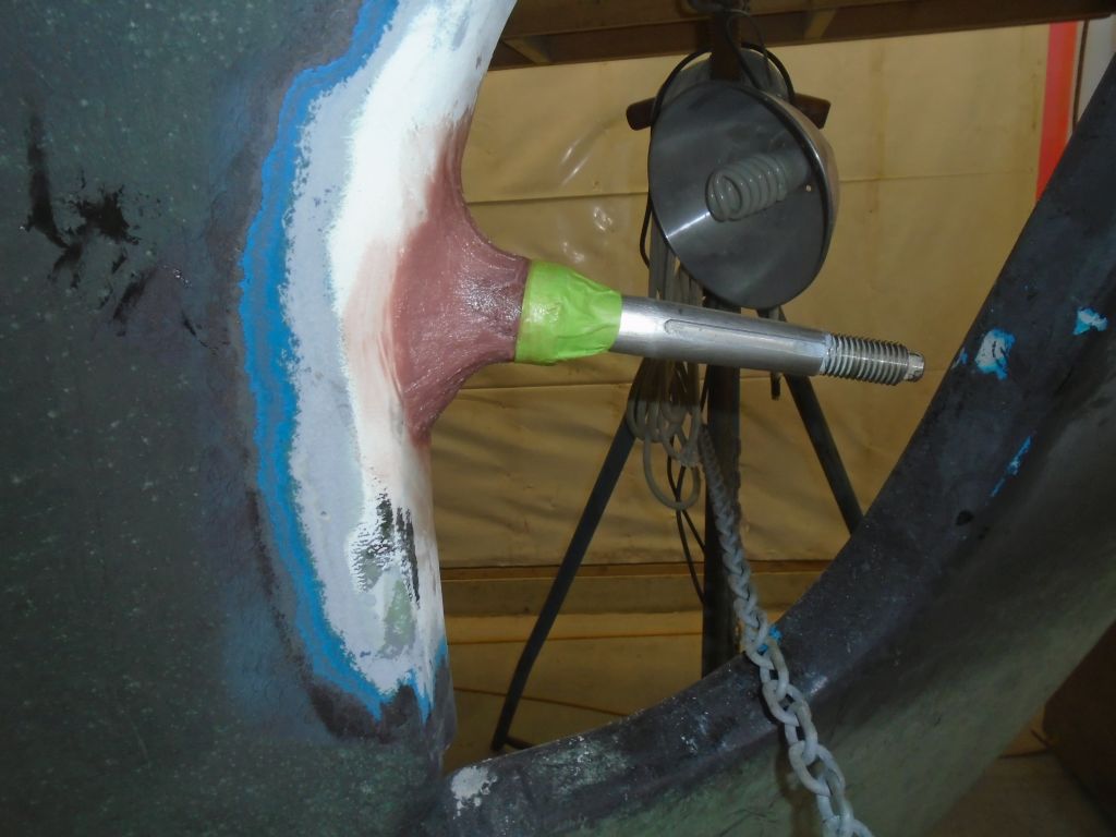
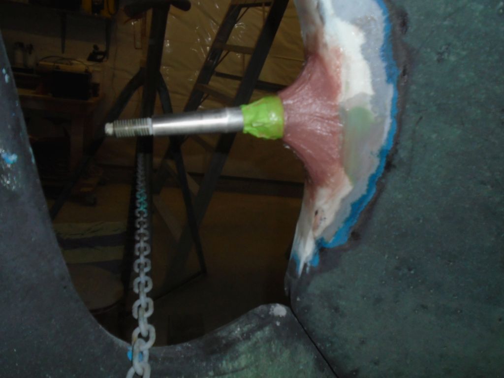
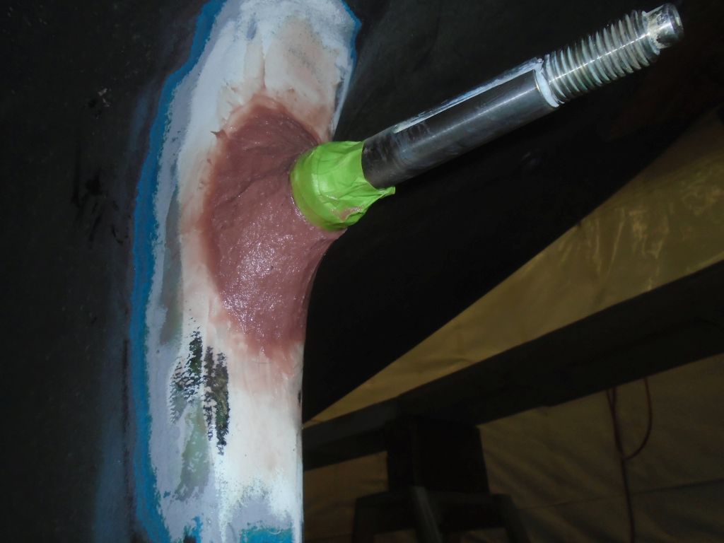
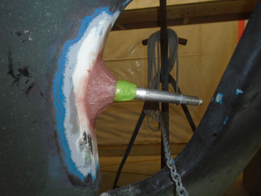
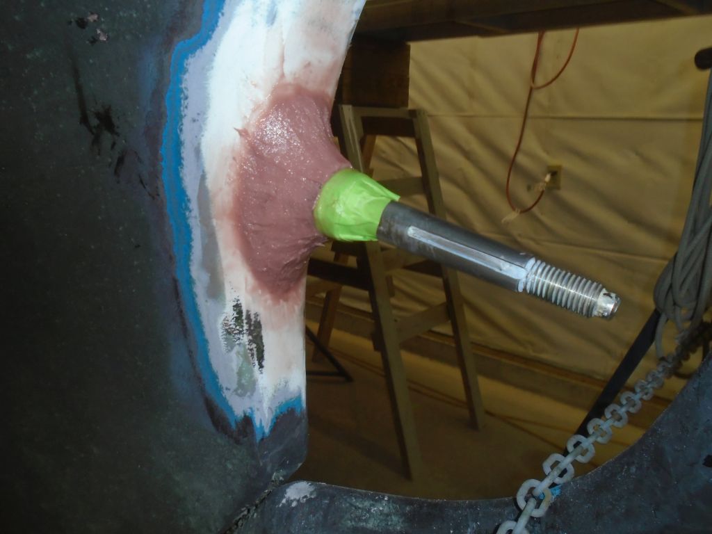
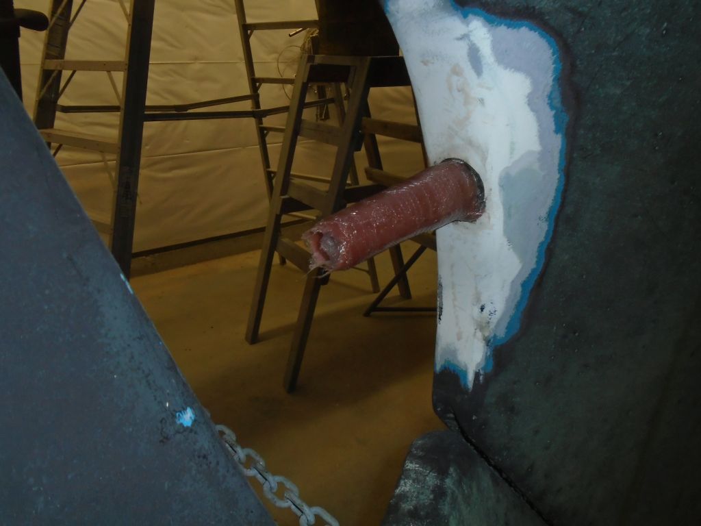
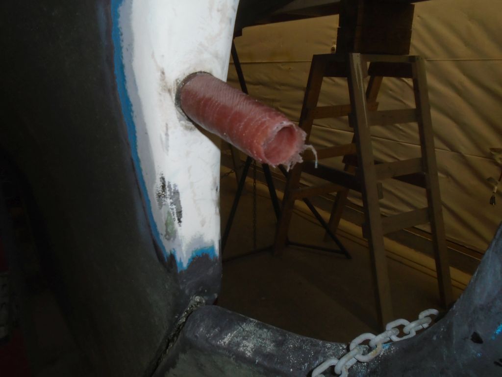
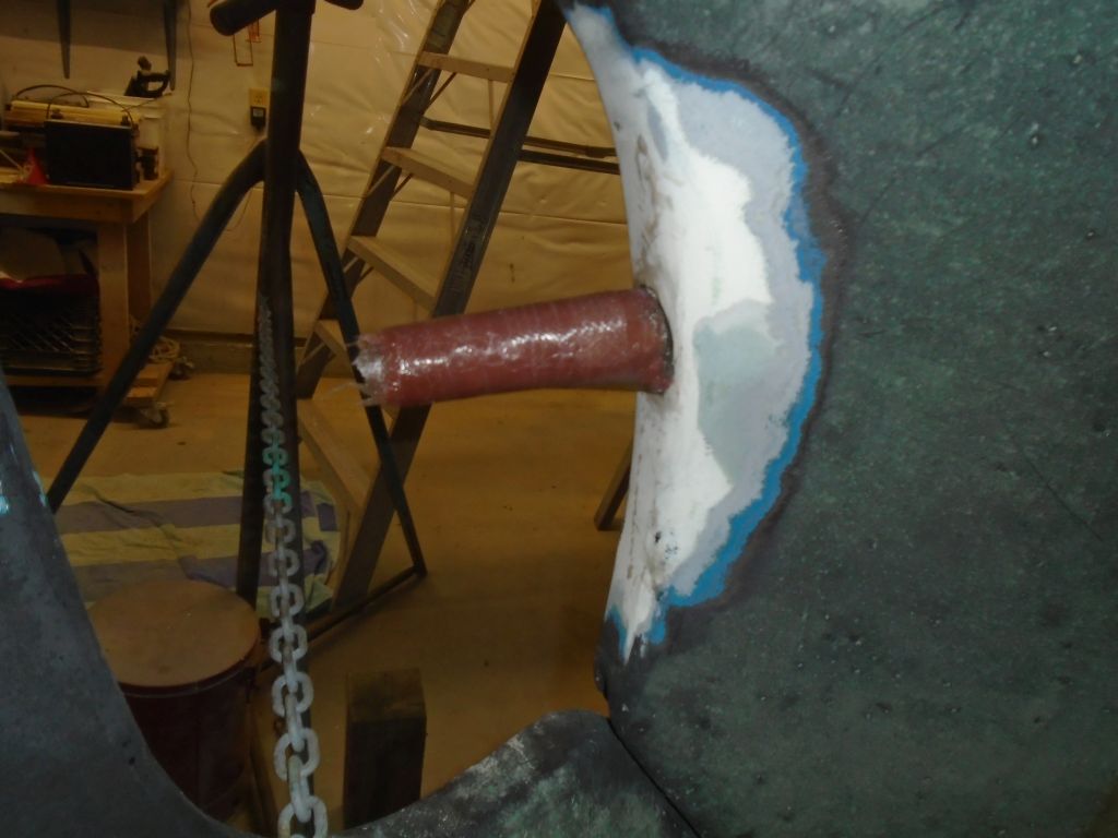
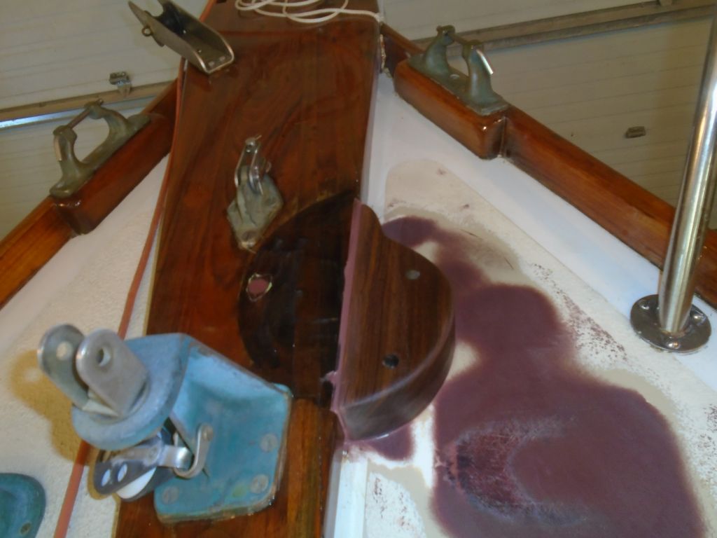
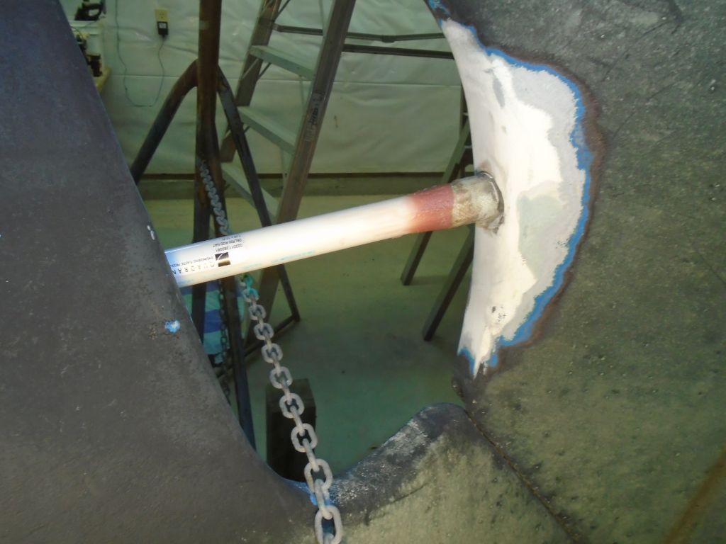
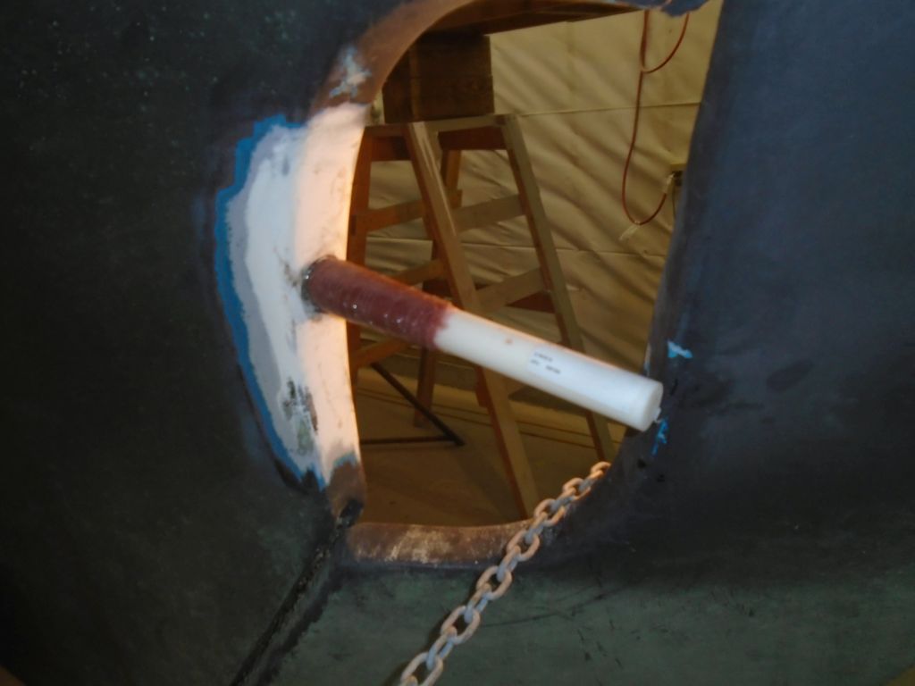
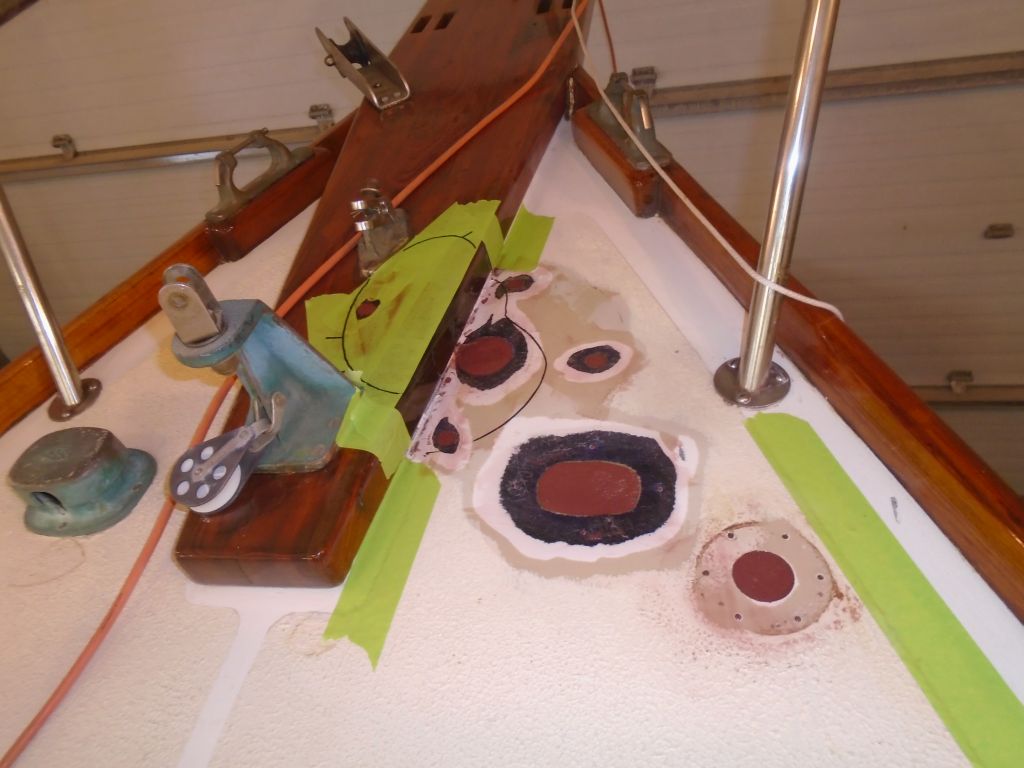
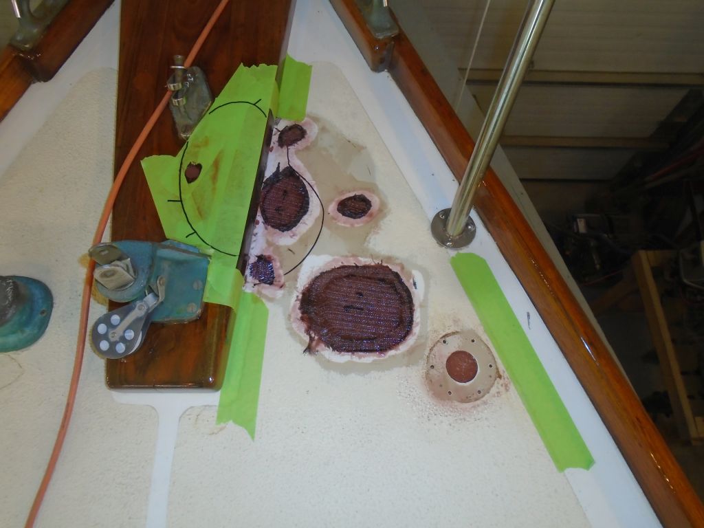
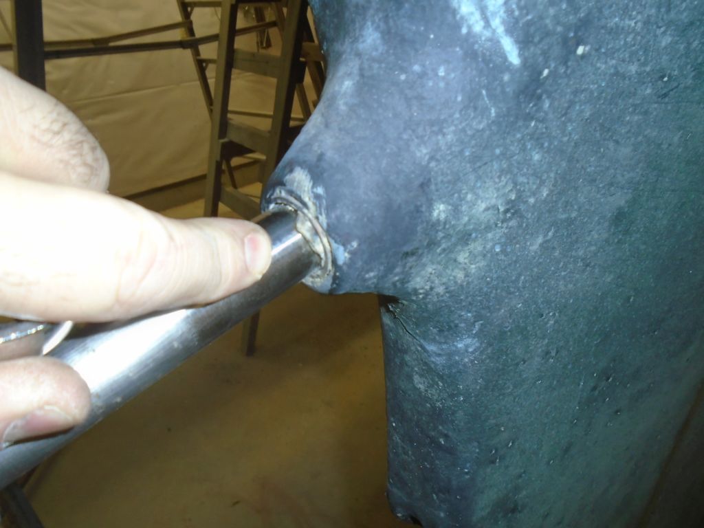
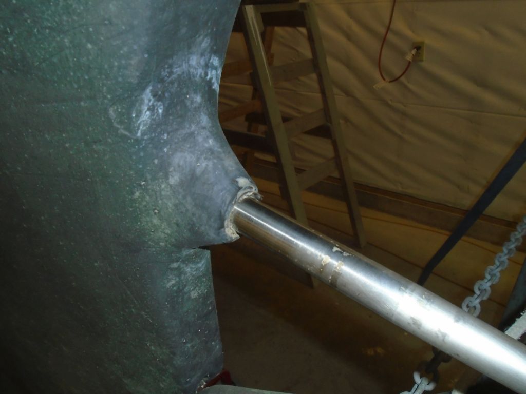
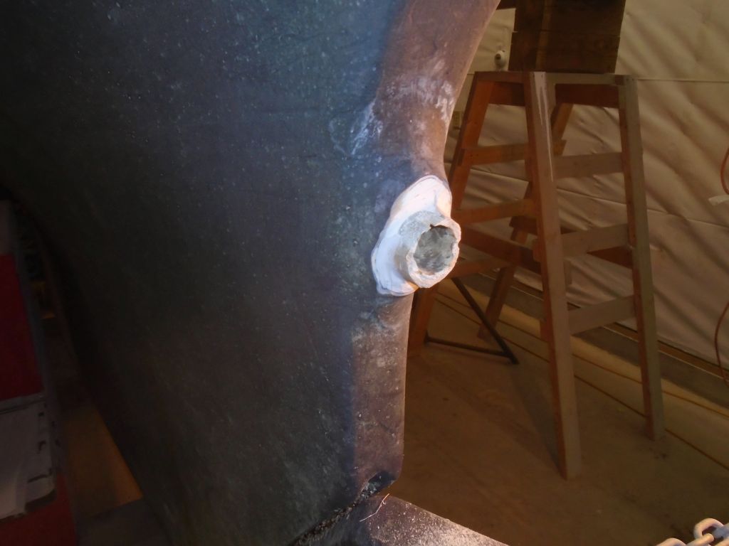
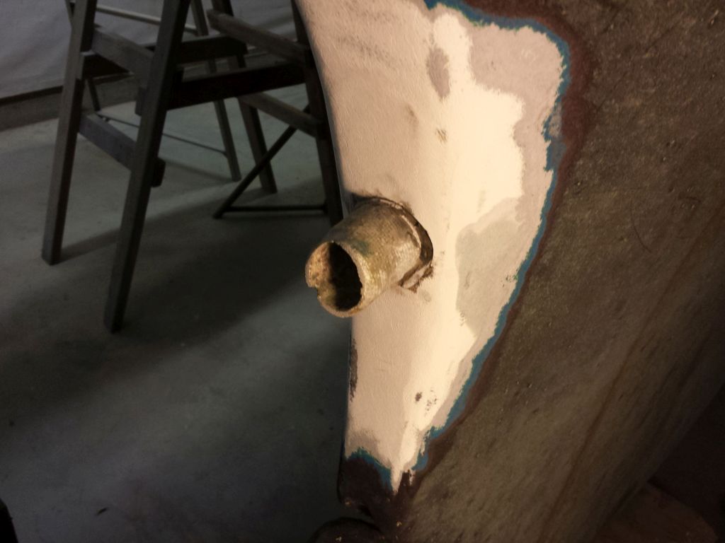
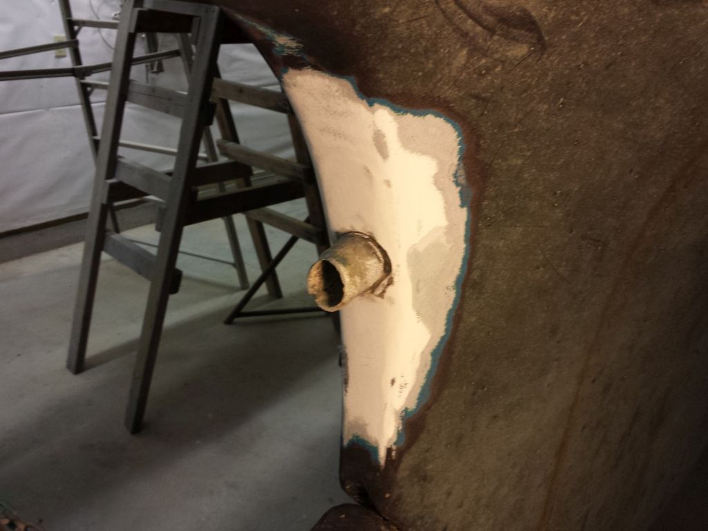
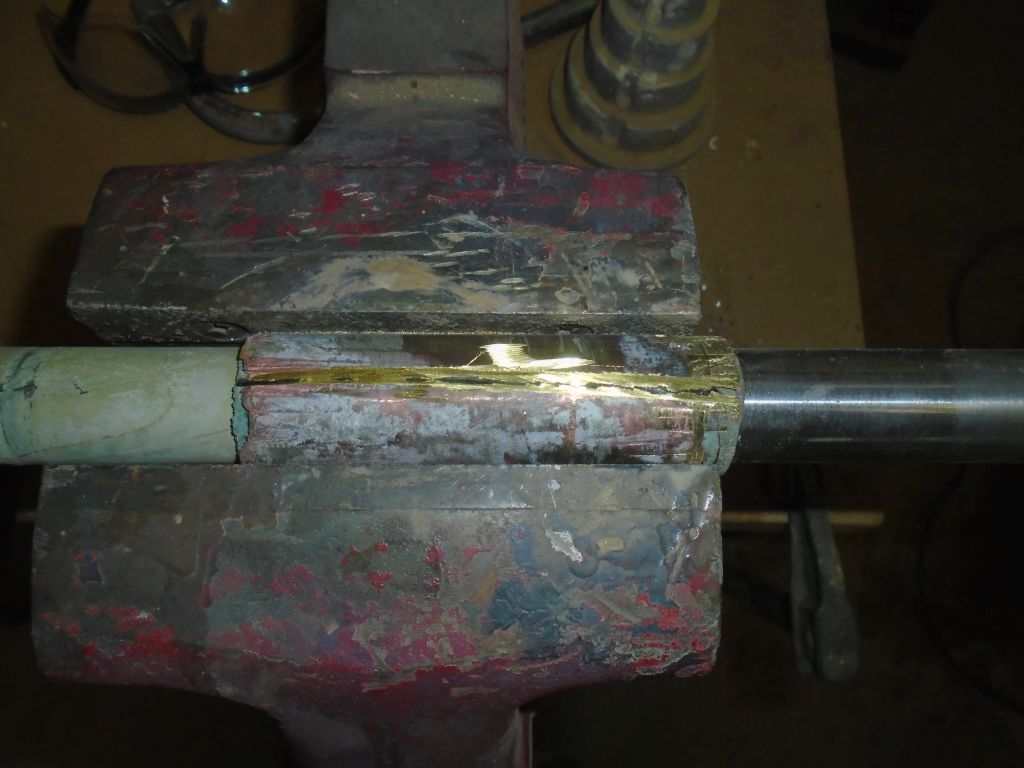
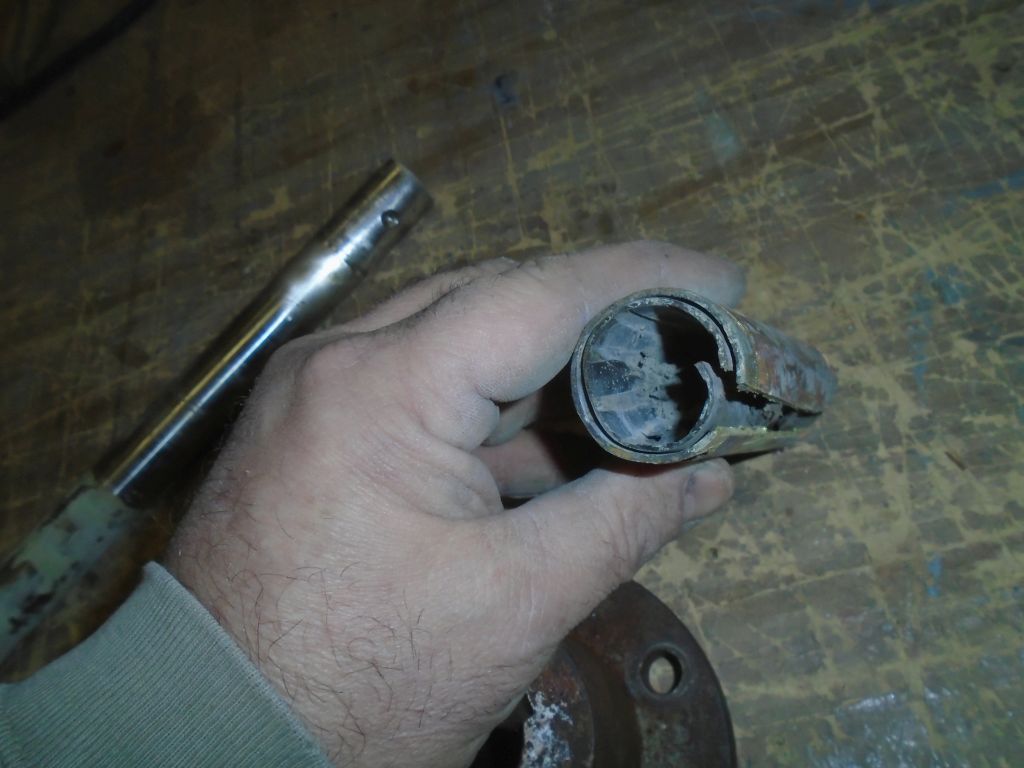
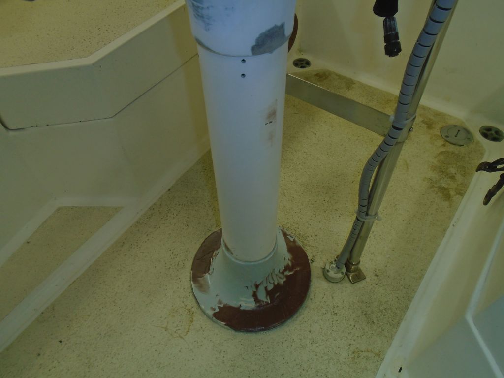
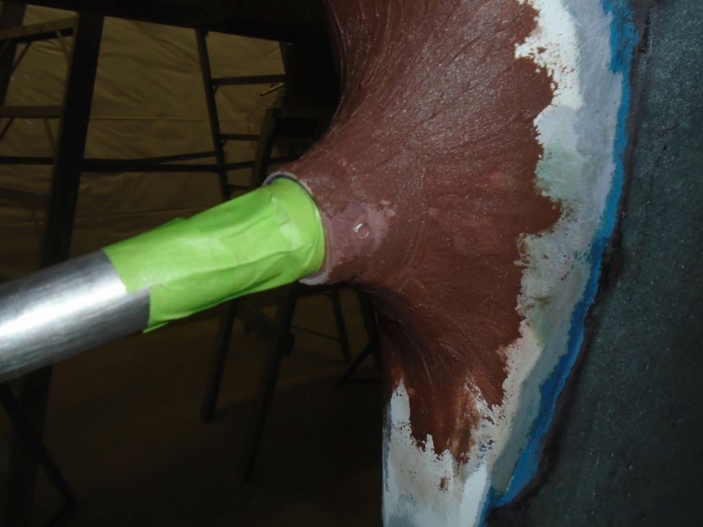
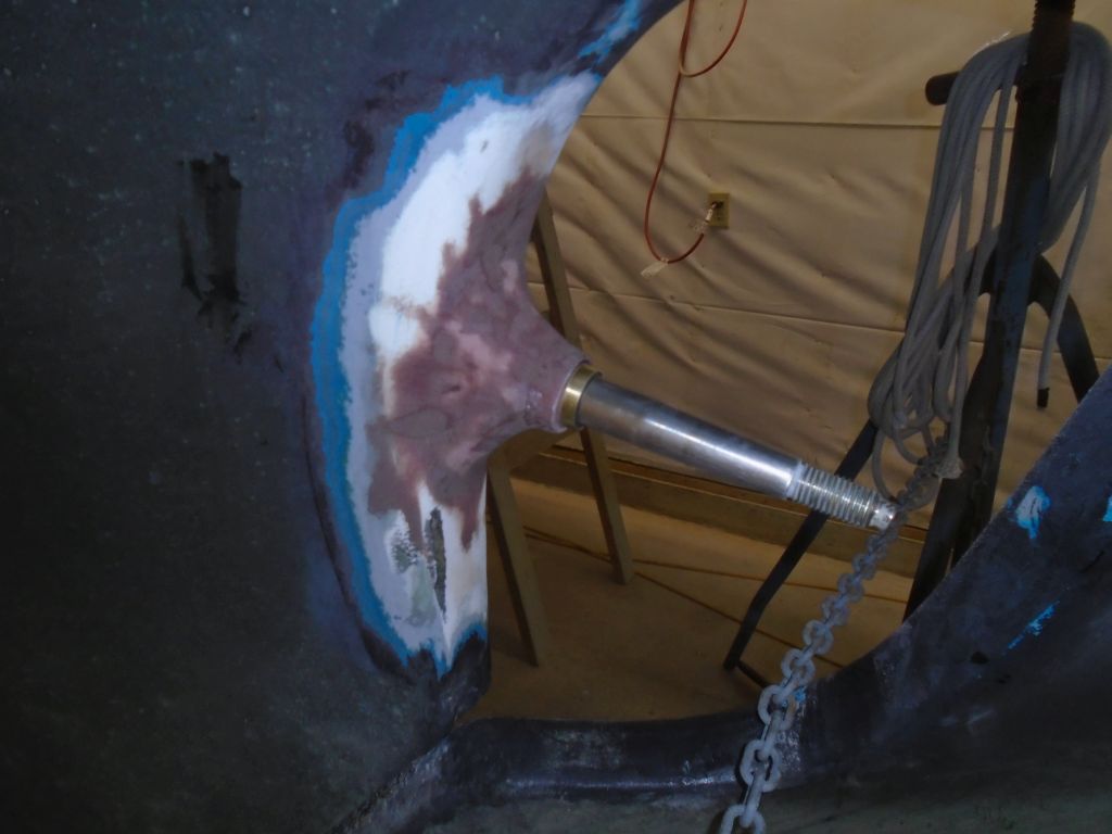
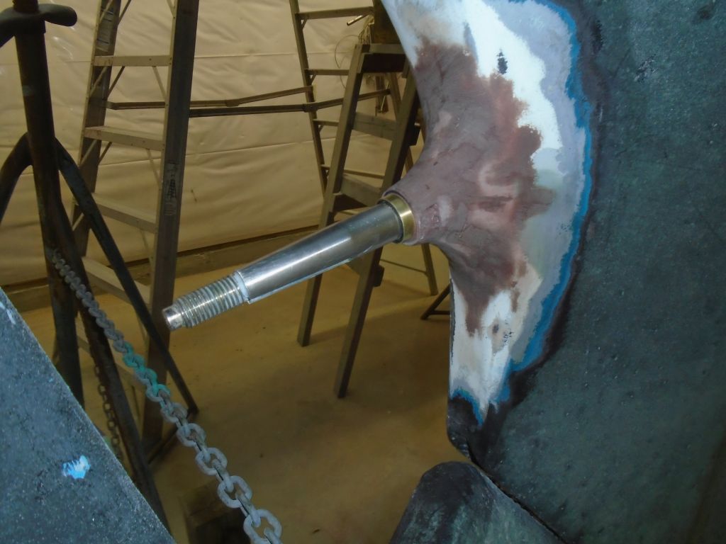
Over the weekend, in two separate events, I continued work on the stern tube and sanded and fine-tuned the new fairing with additional epoxy material, sanding between rounds.
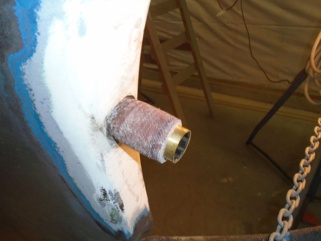
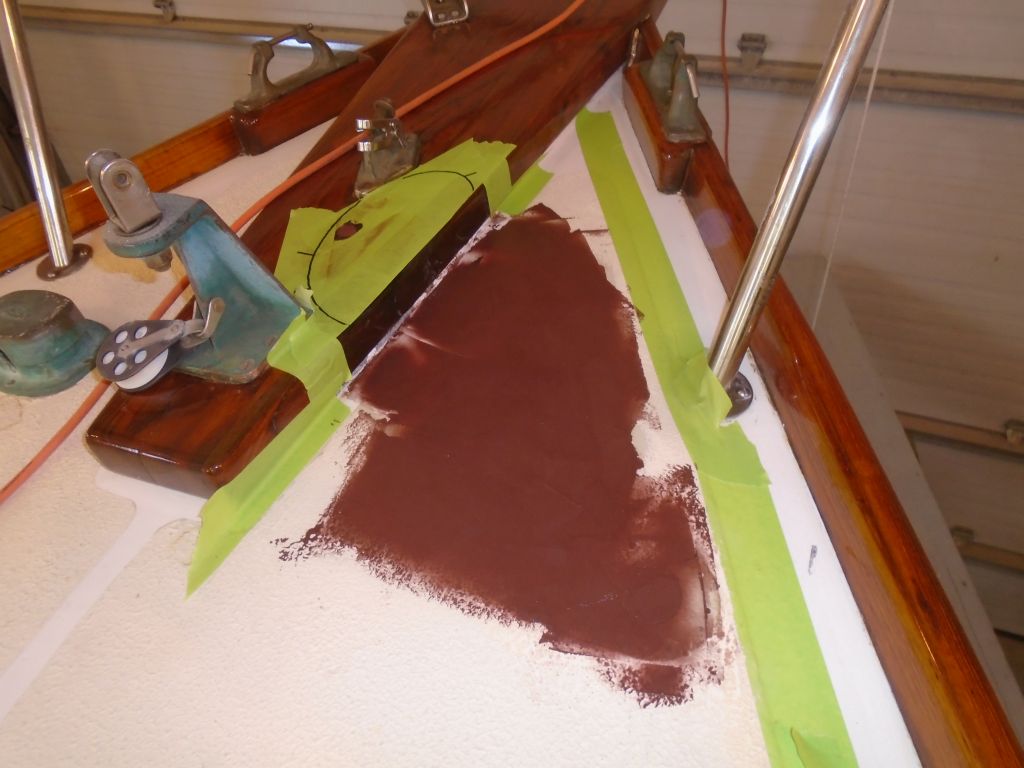
Round 1:

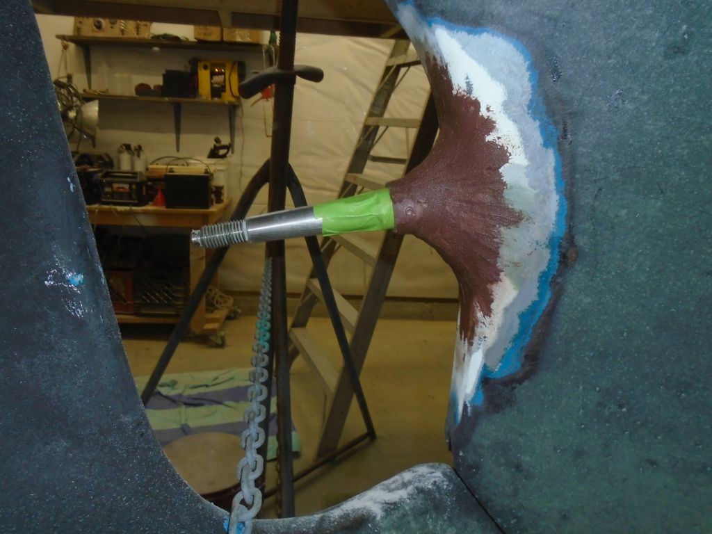
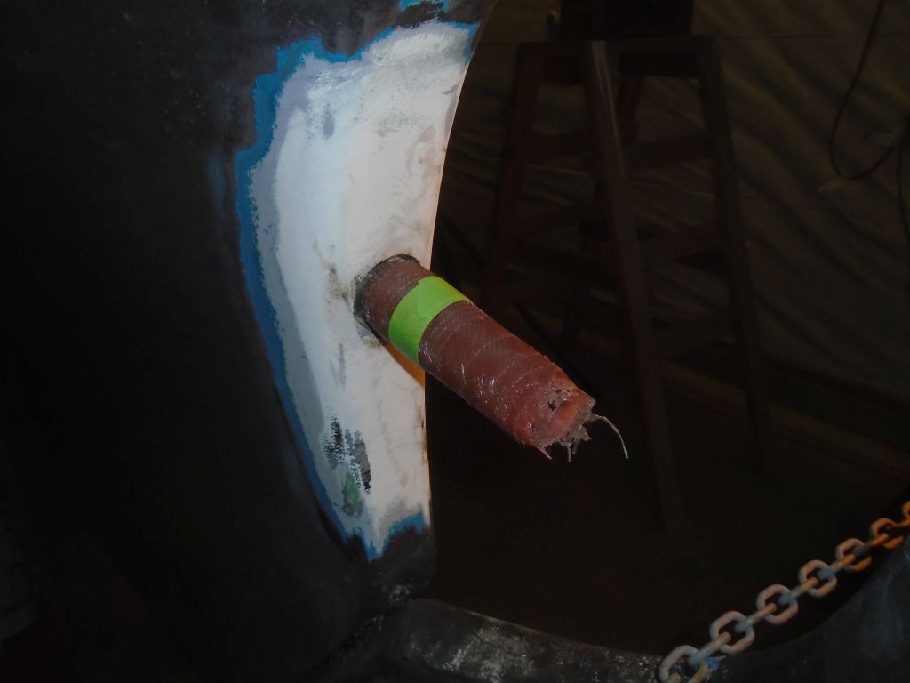
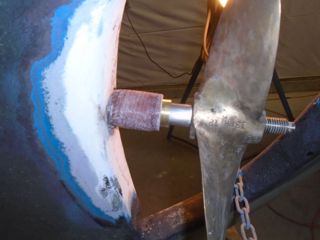
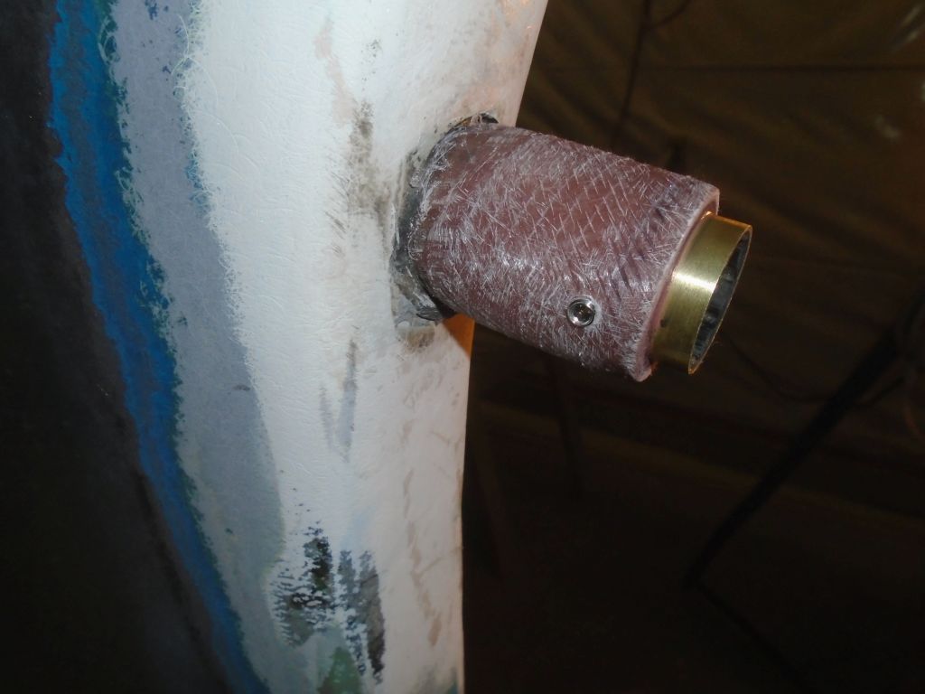
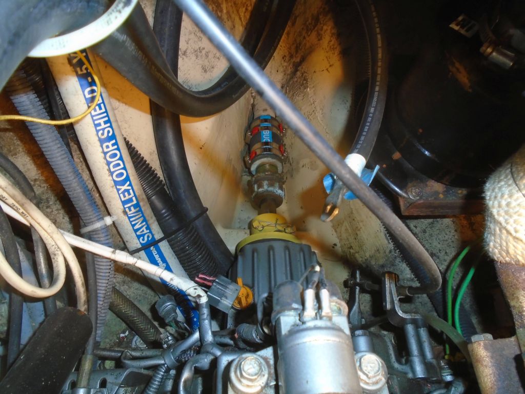
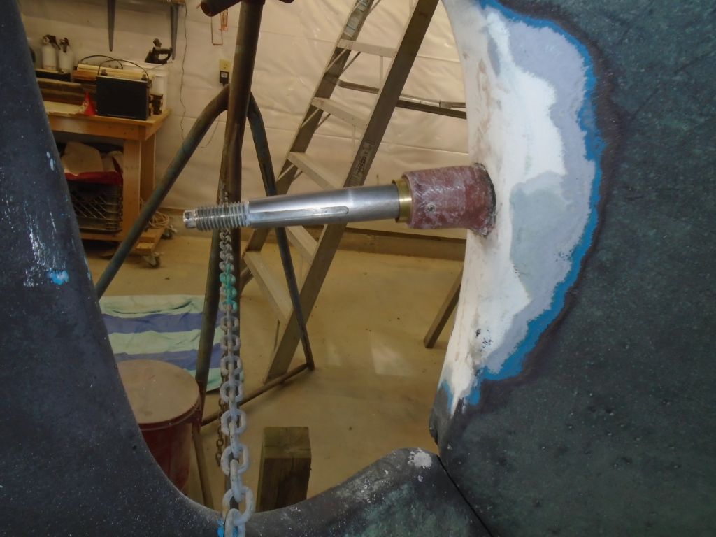
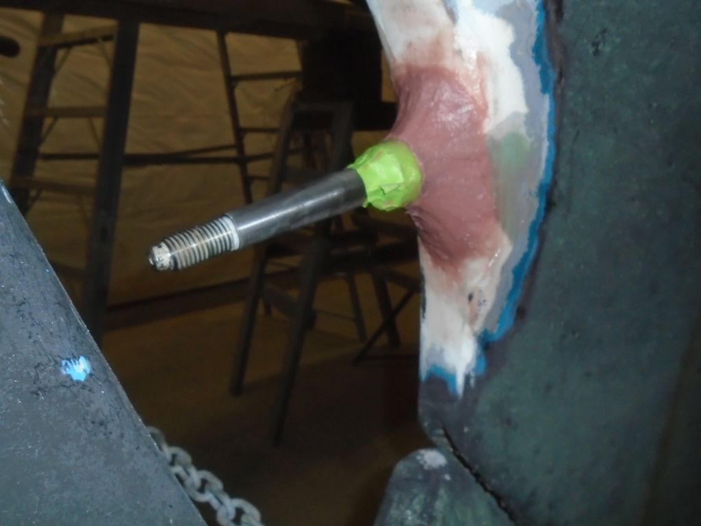
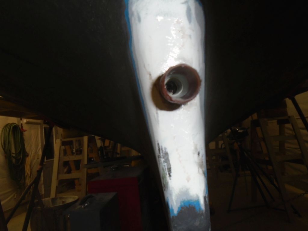
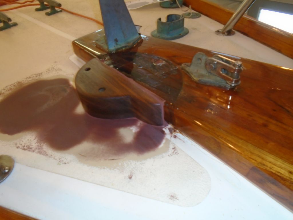
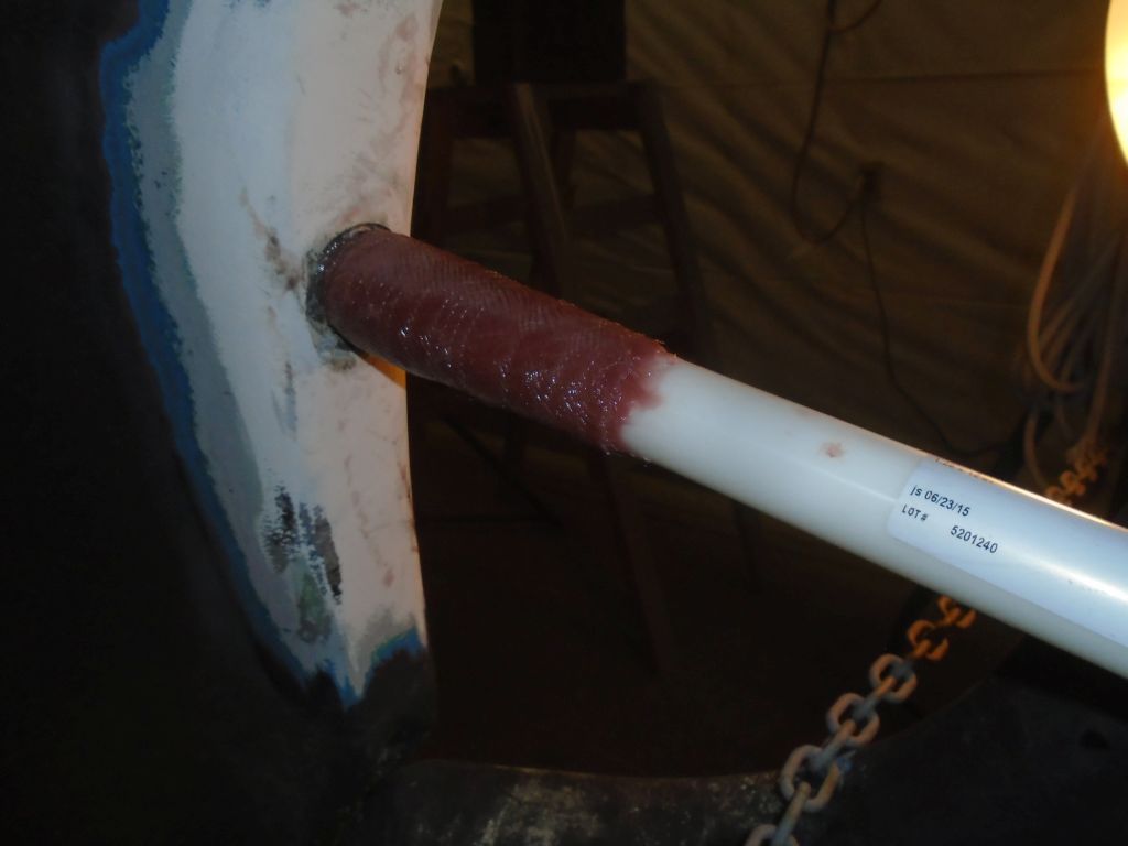
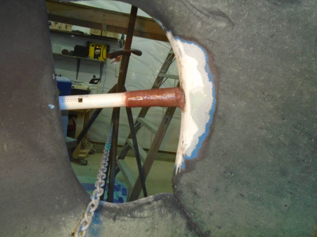
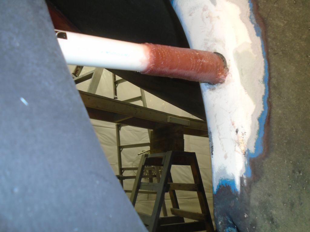
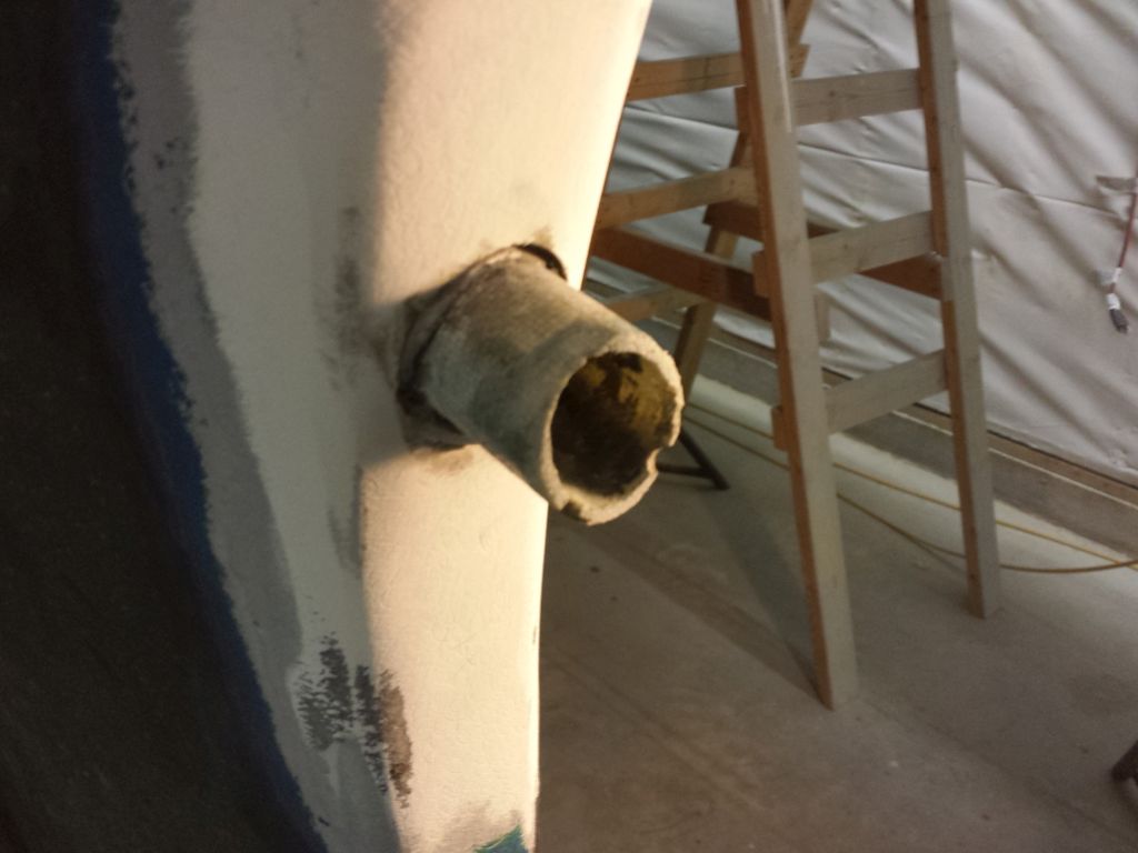
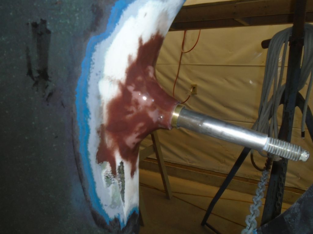
Round 2, which was a minor fairing to take care of a few lingering low spots:

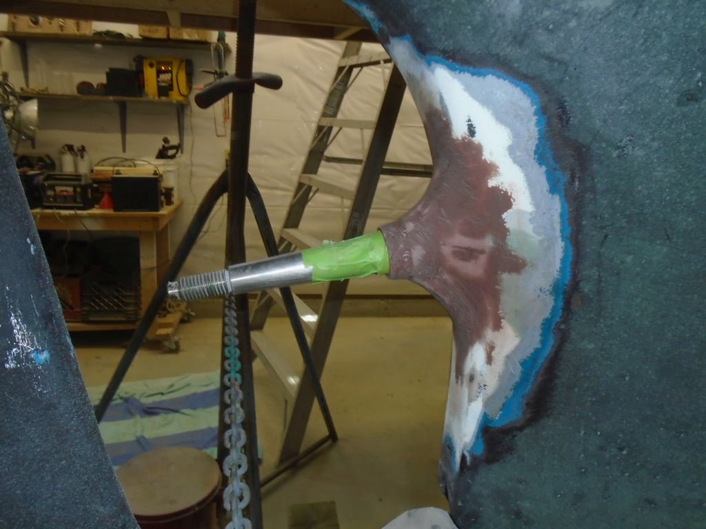
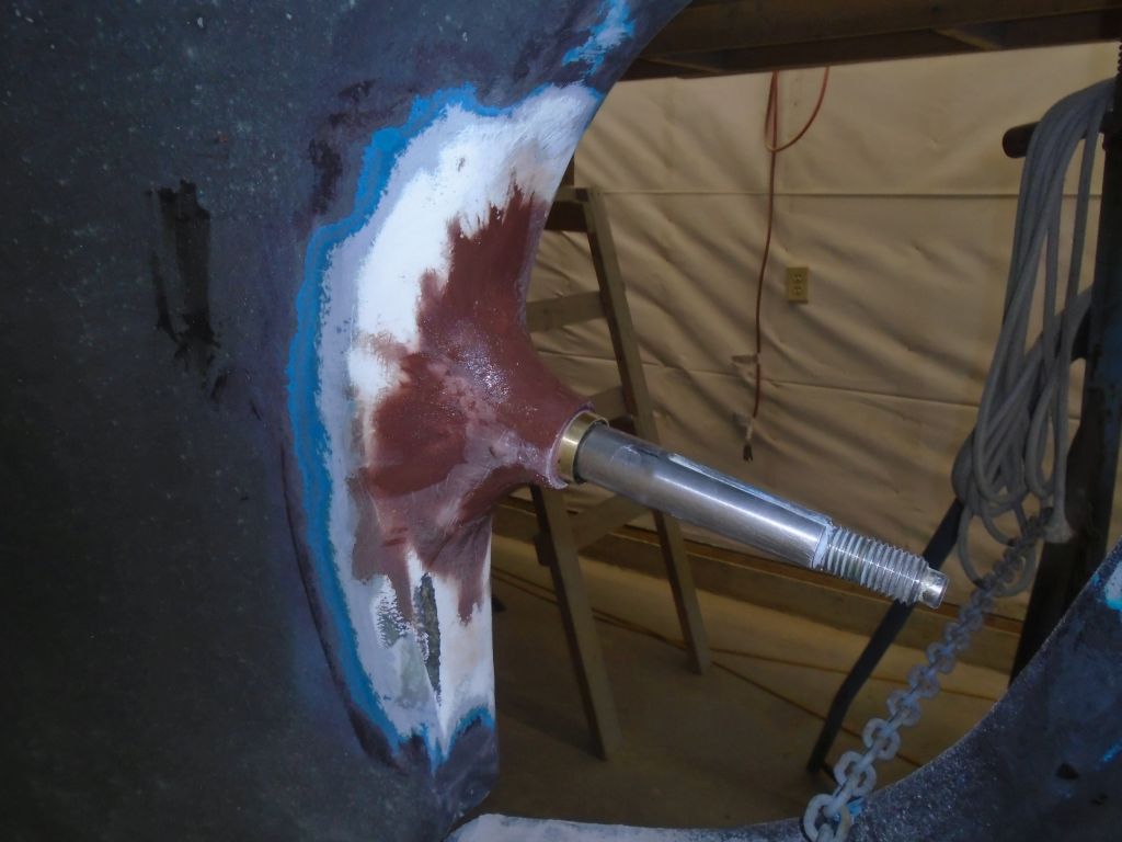
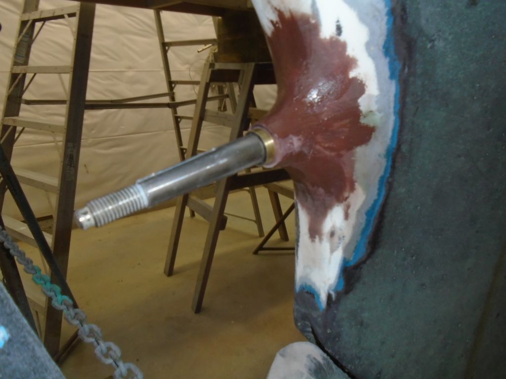
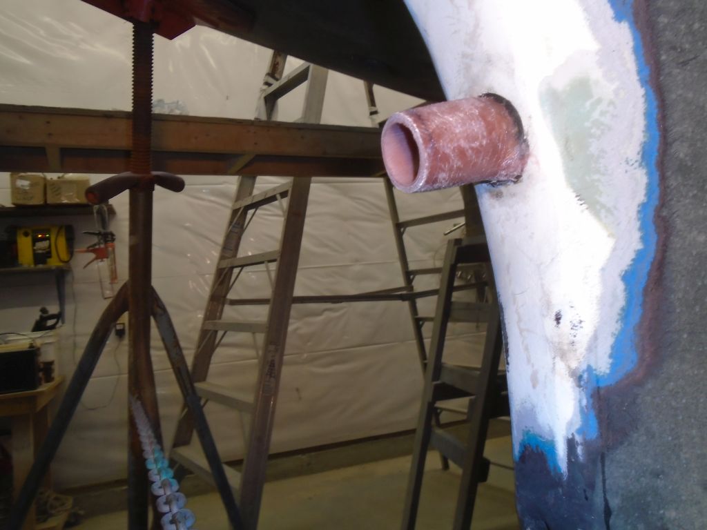
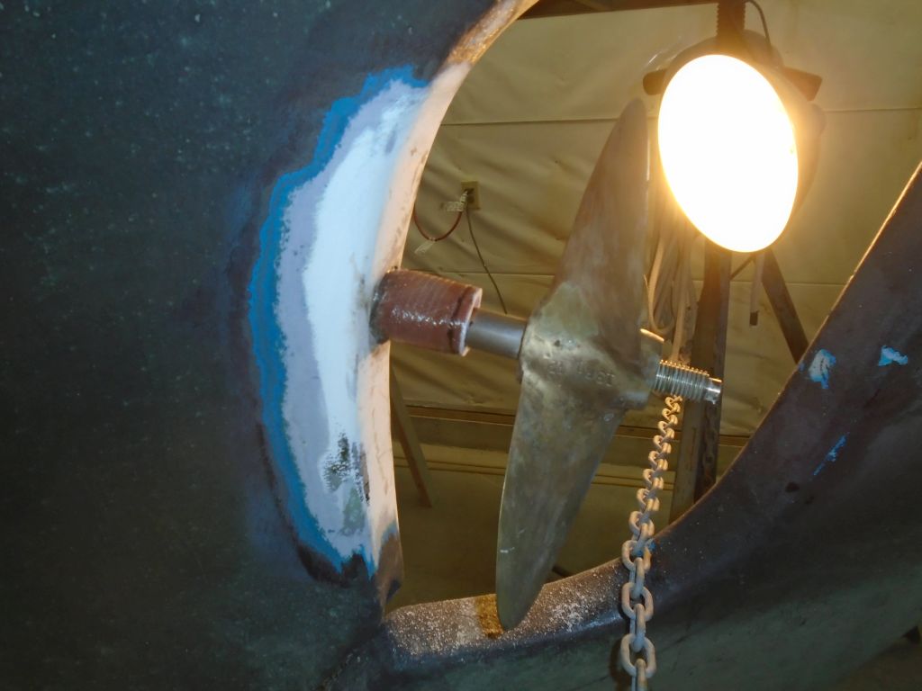
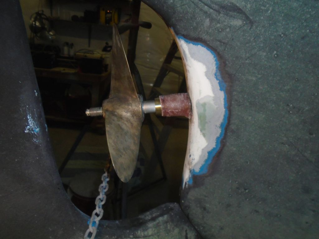
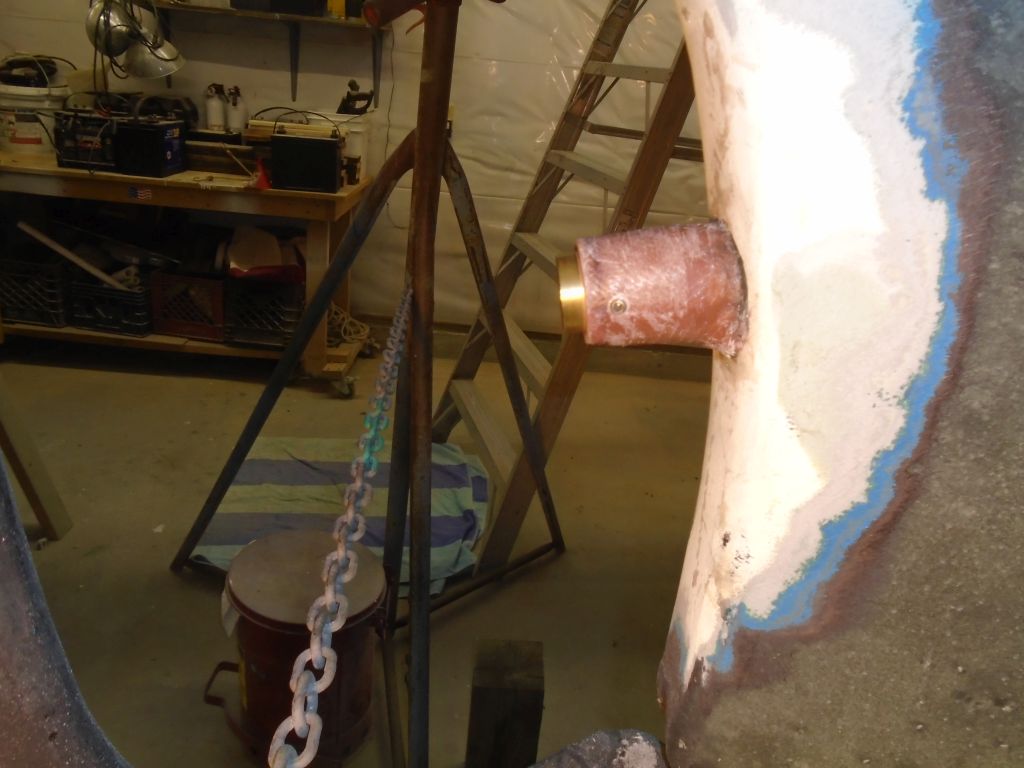
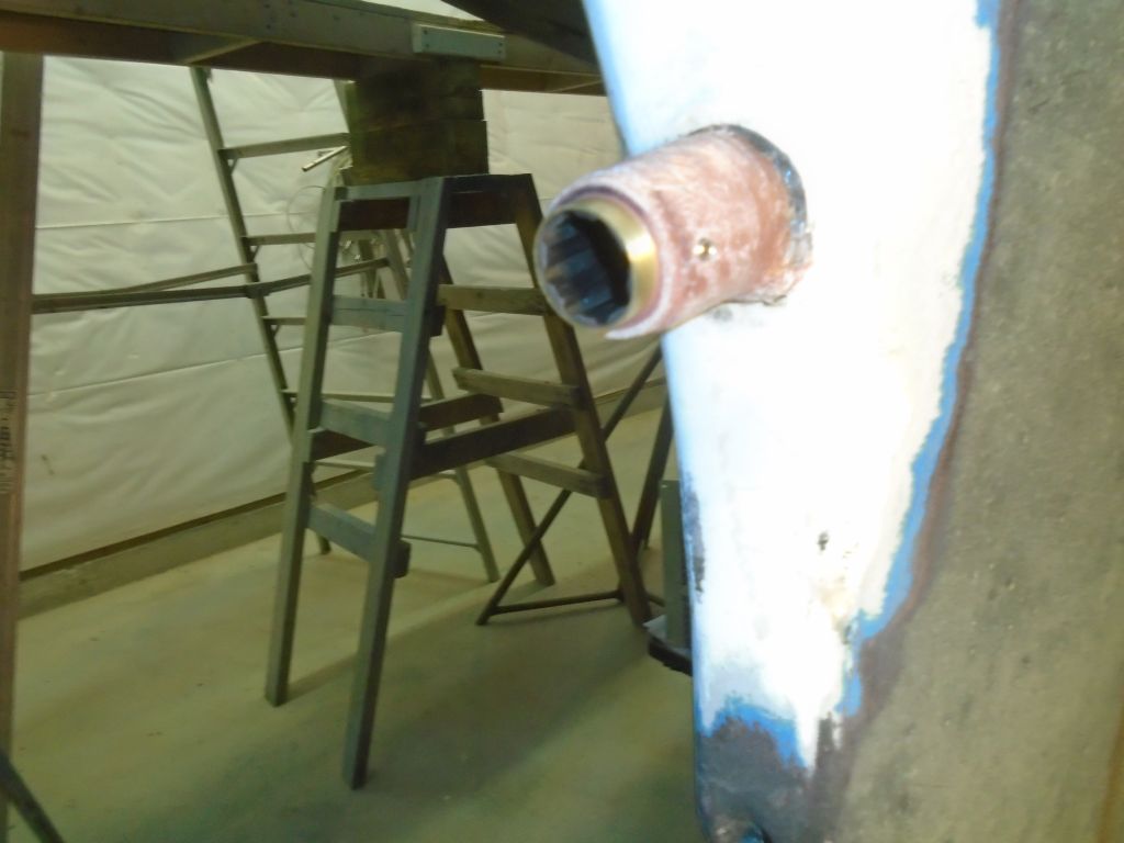
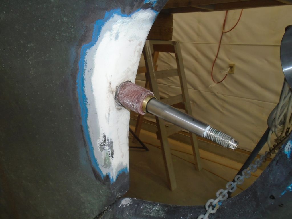
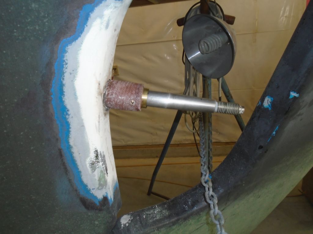
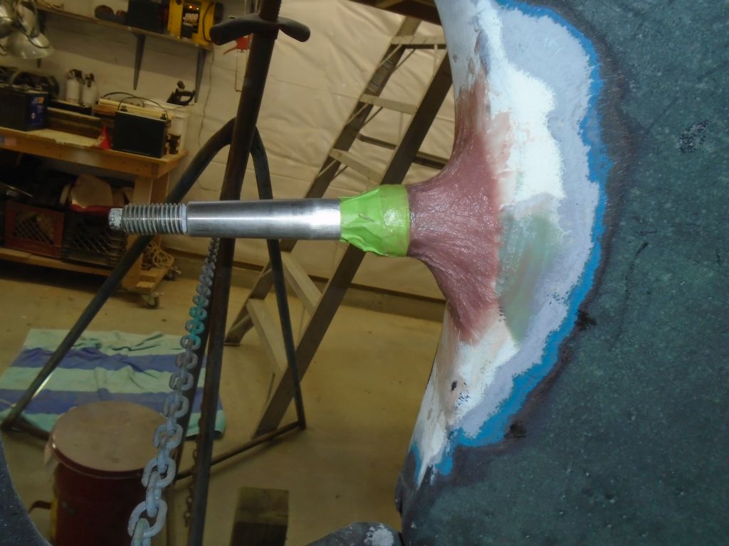
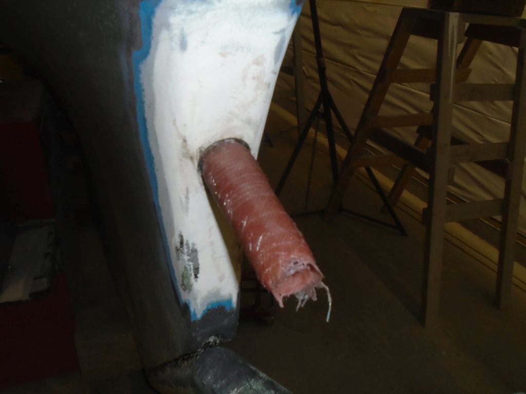
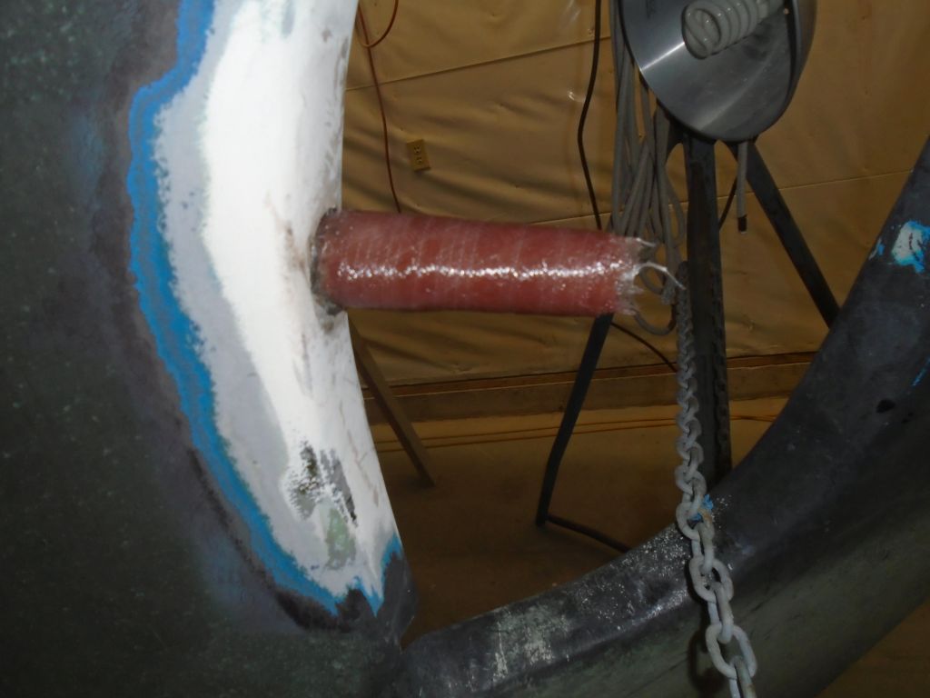
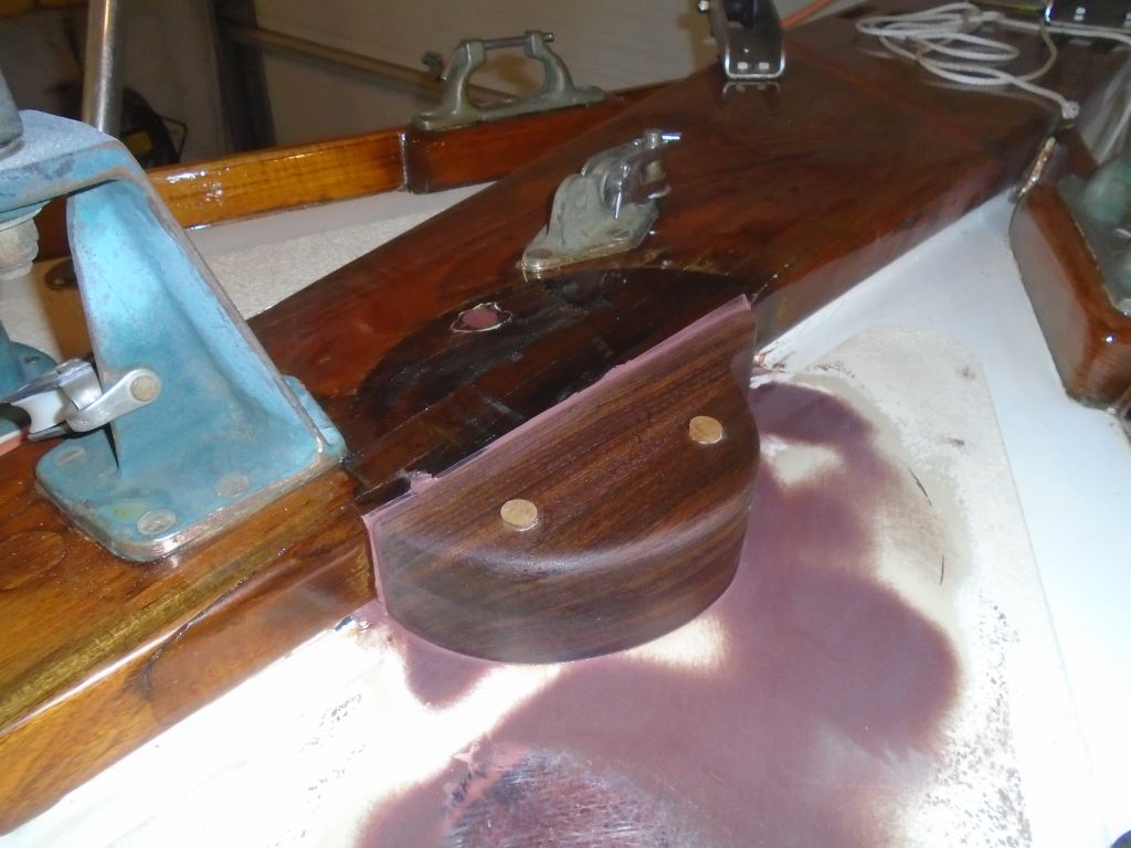
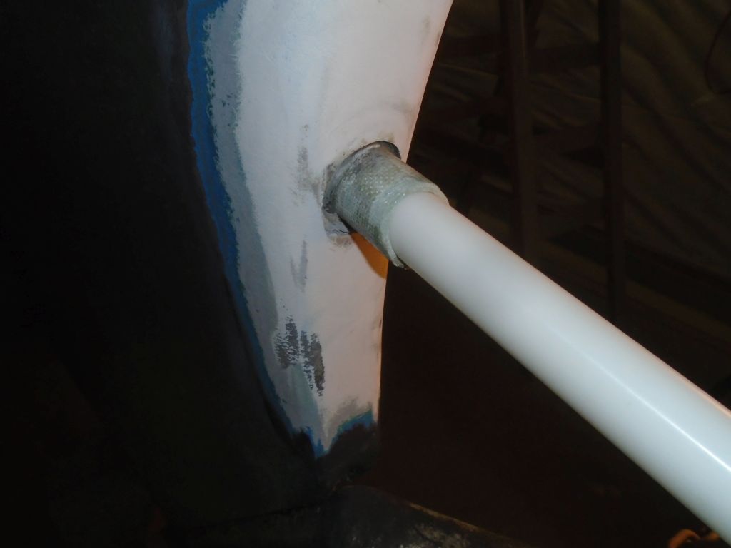
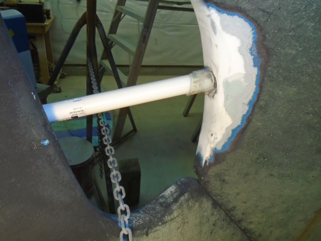
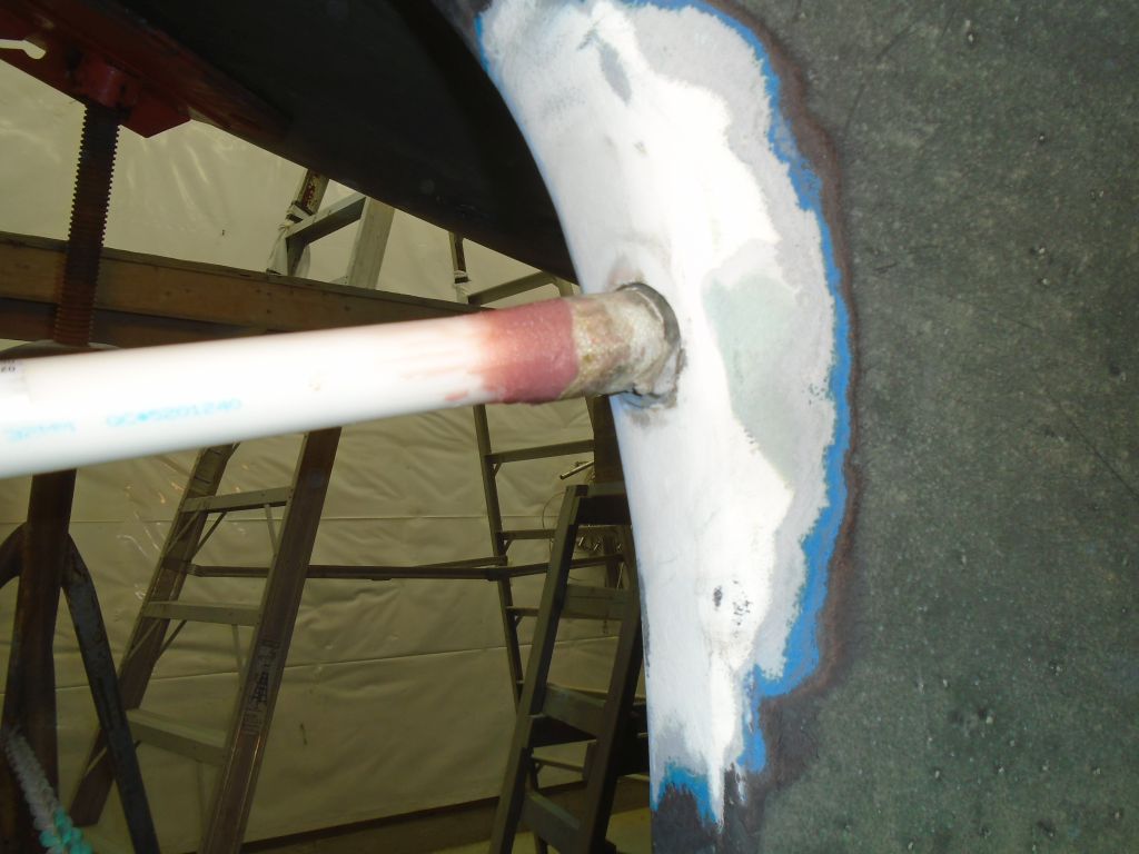
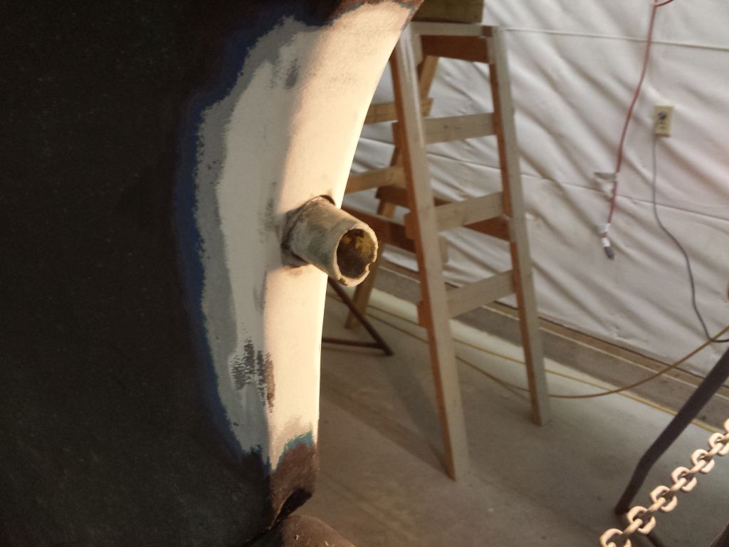
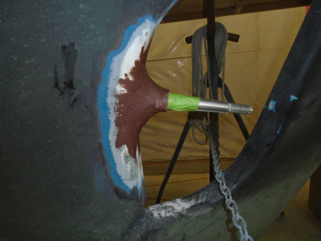
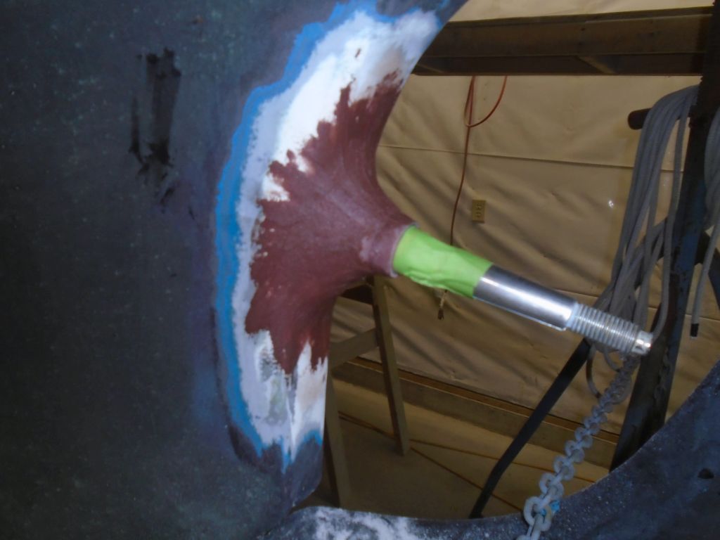
Now, I washed and lightly sanded the aperture a final time to smooth the last application of fairing compound.  To finish off the area, once I’d cleaned up I applied a coat of unthickened epoxy as a sort of sealer for the fairing compounds beneath, and left it to cure.

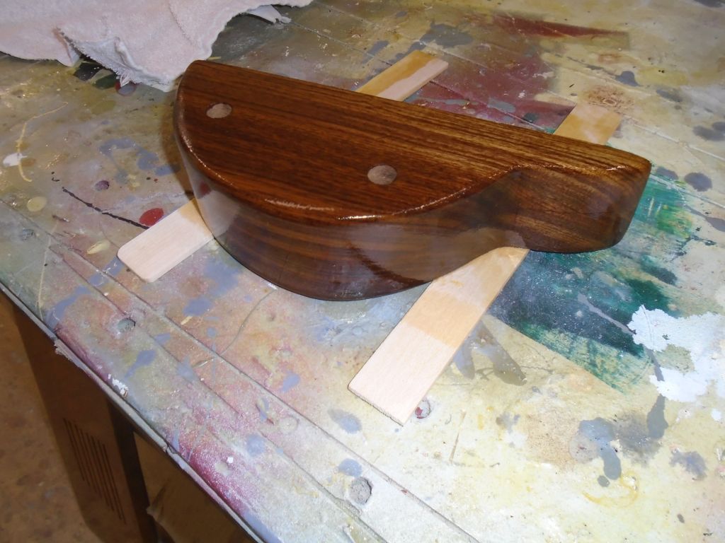
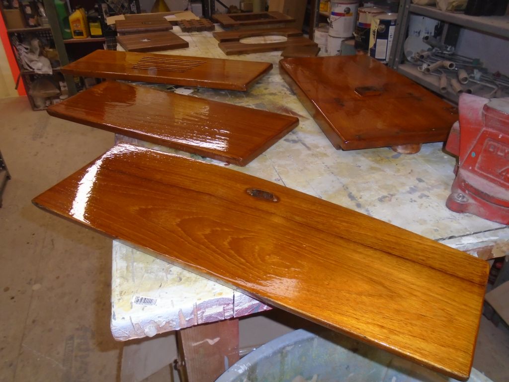
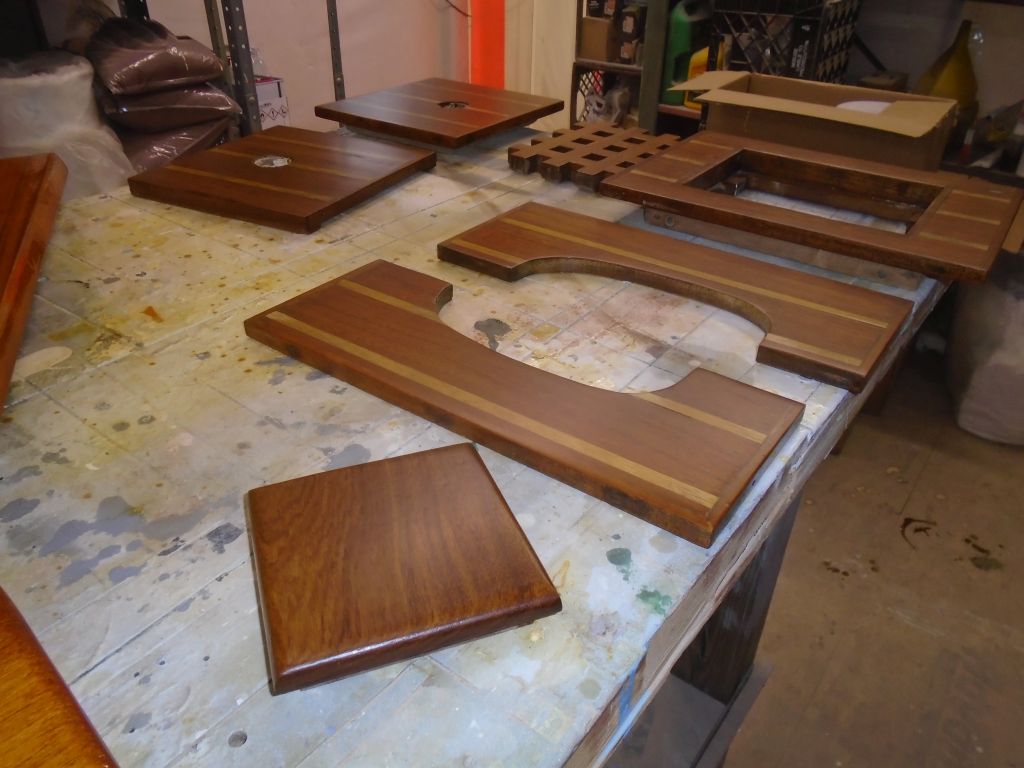
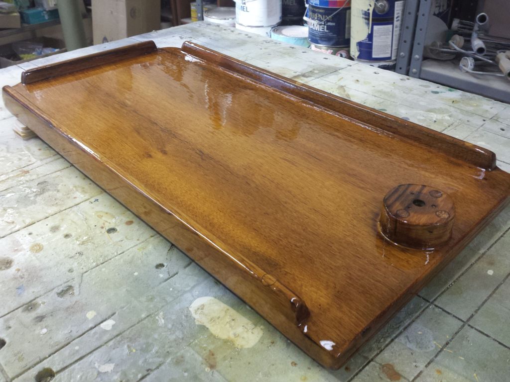
Meanwhile, upstairs I continued varnish work on the cockpit table top.

varnish1-21516

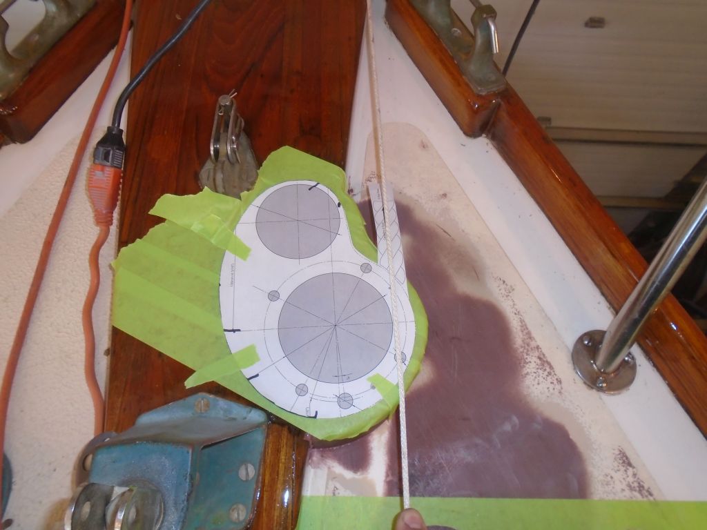
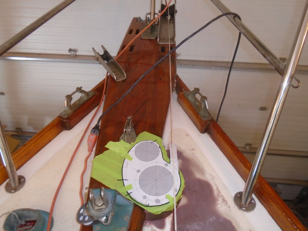
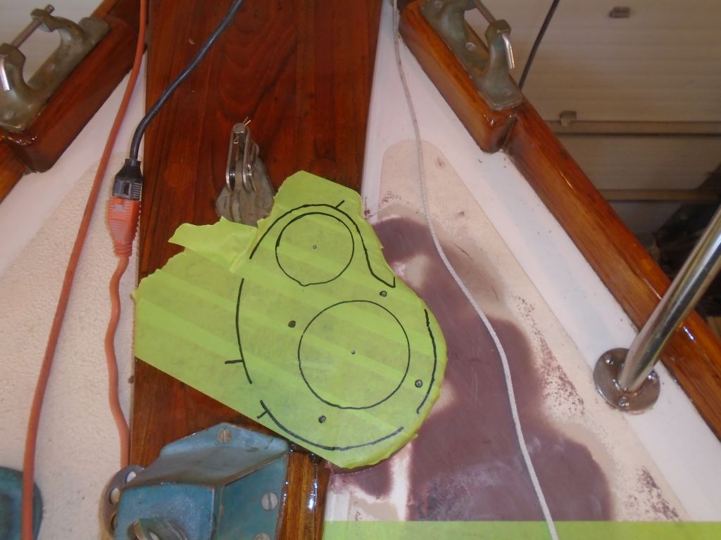
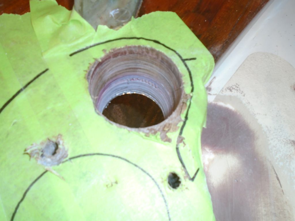
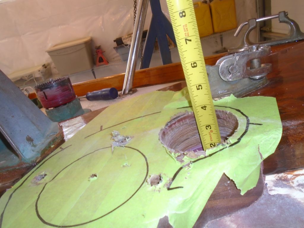
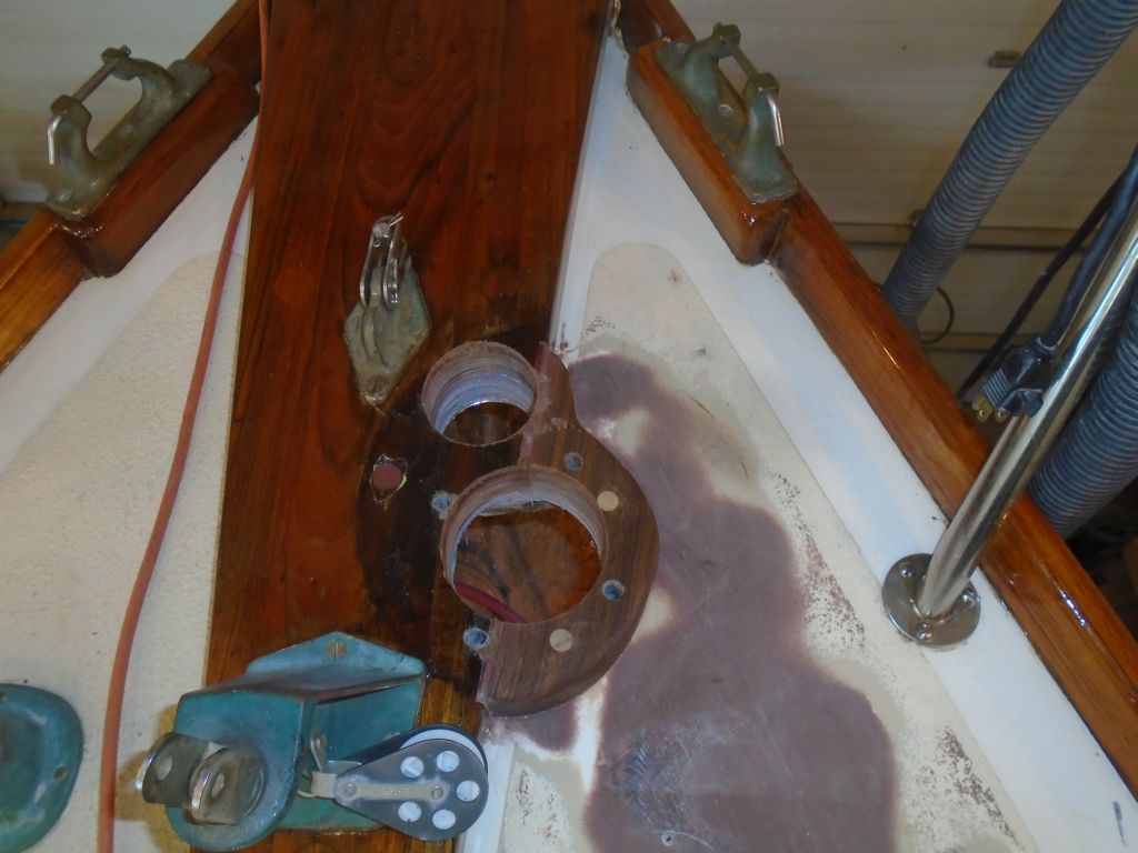
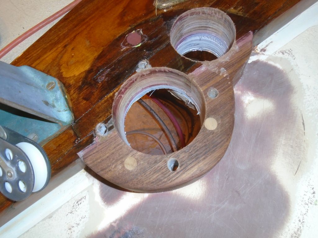
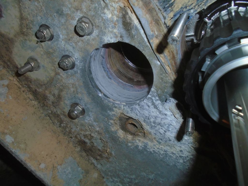
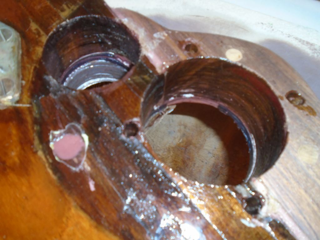
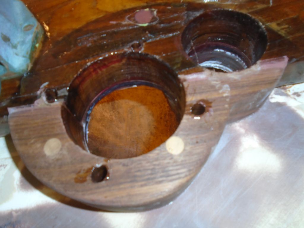
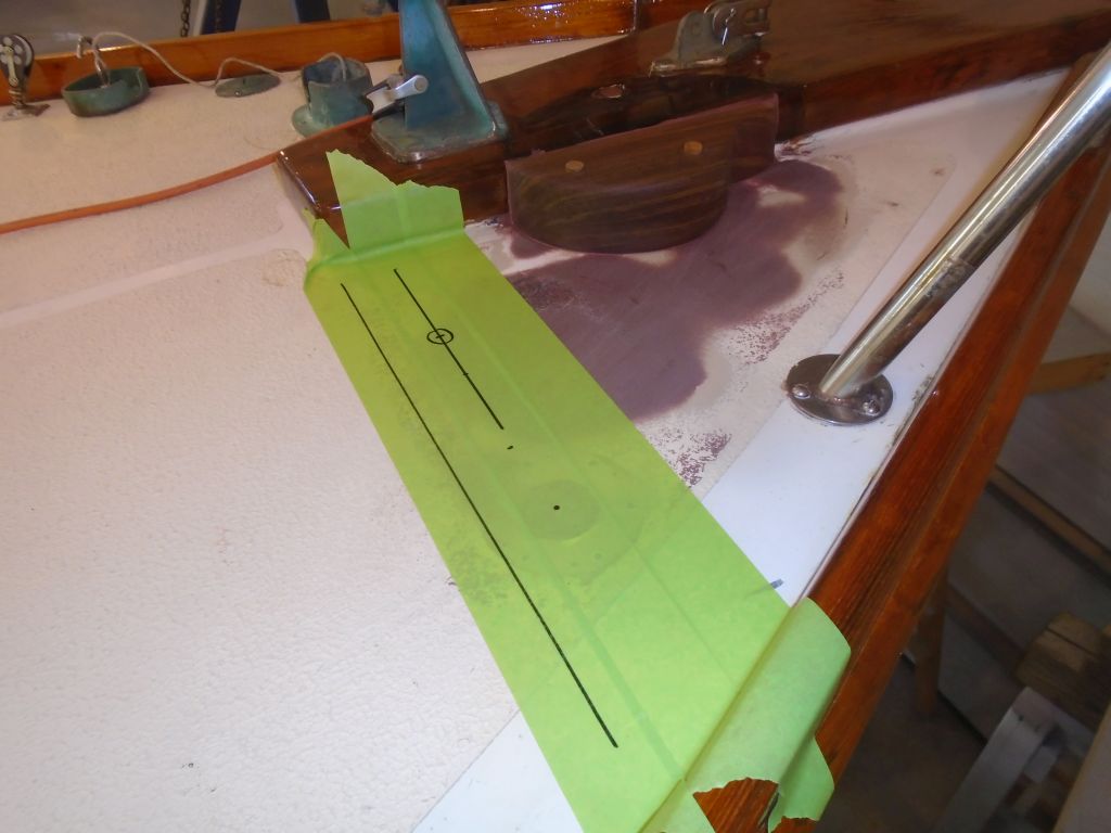
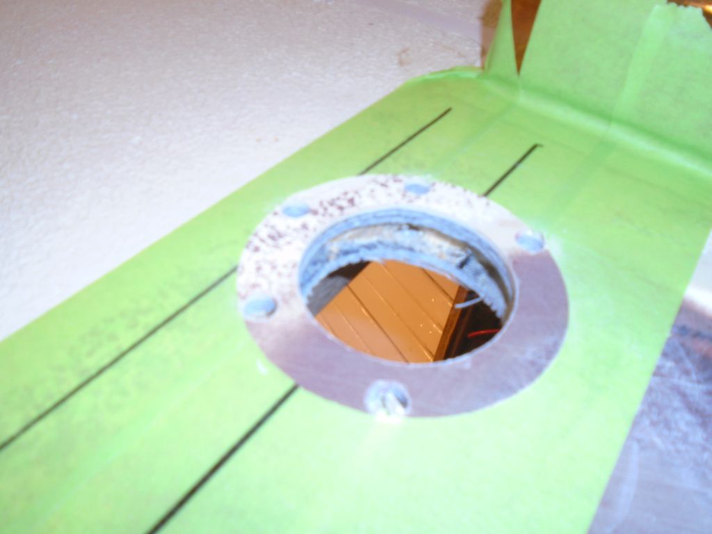
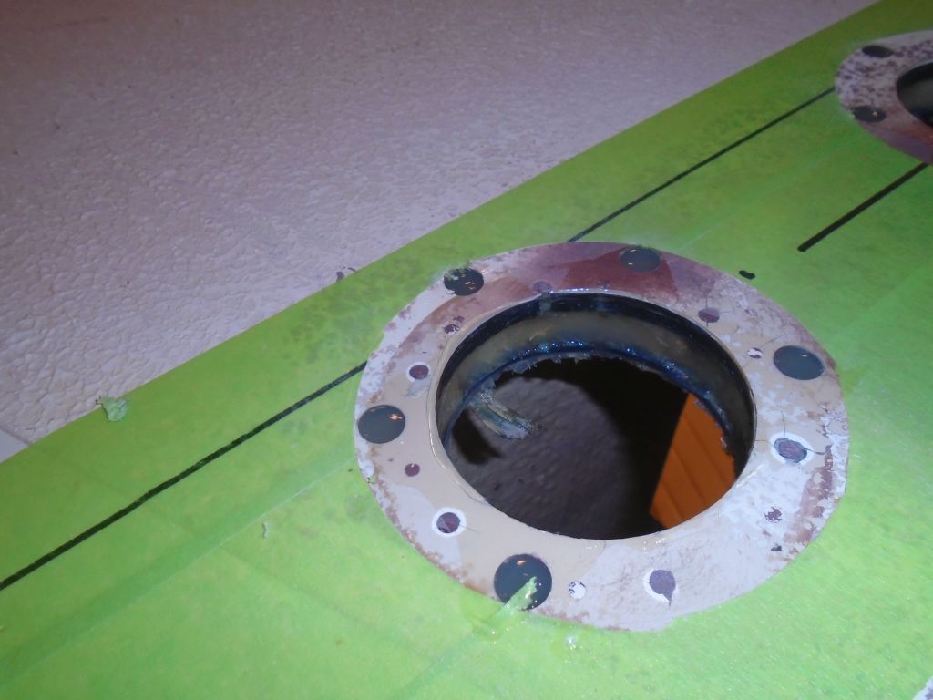
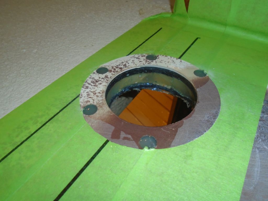
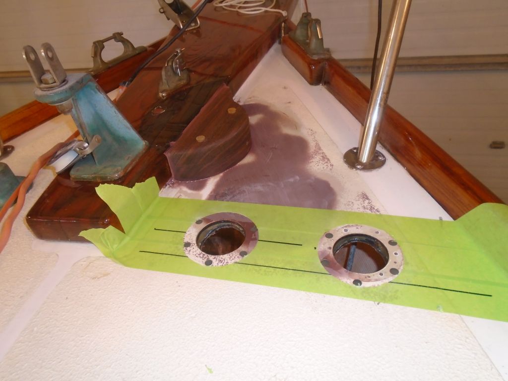
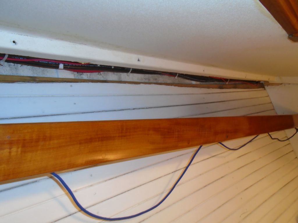
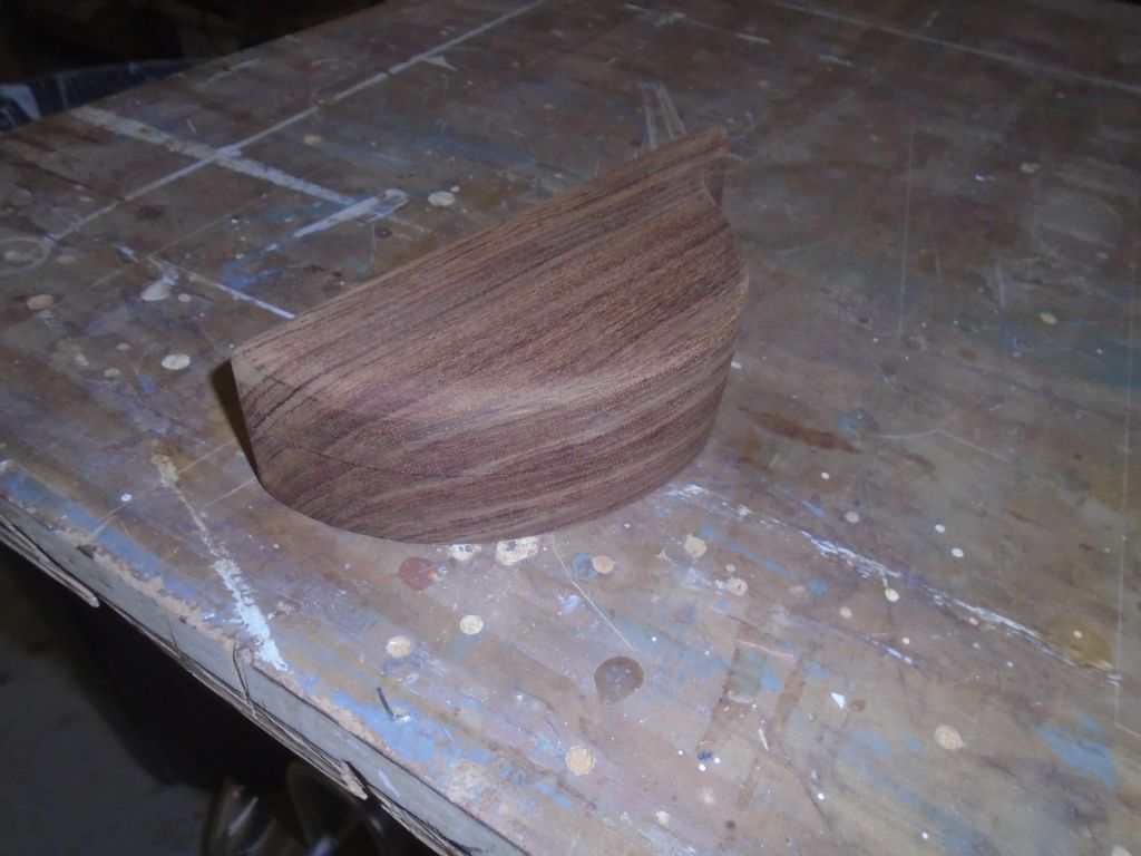
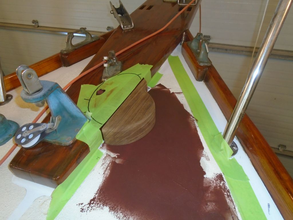
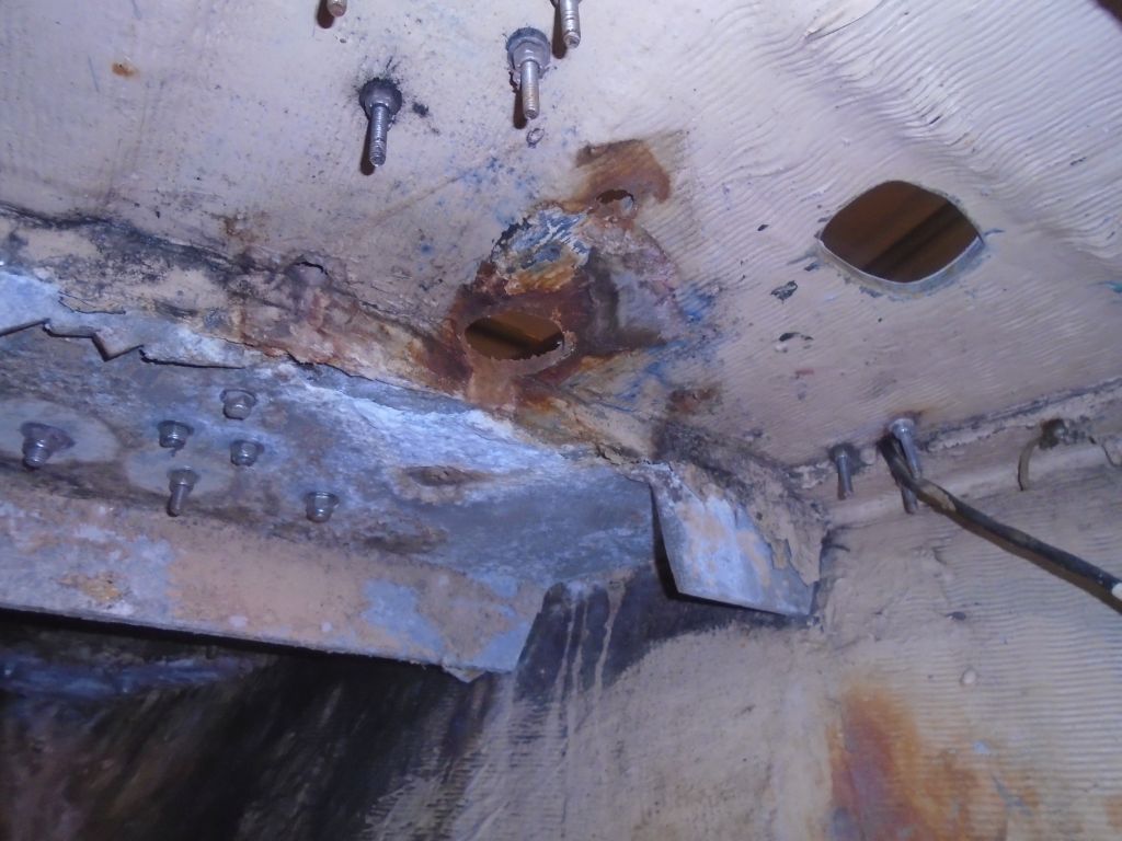
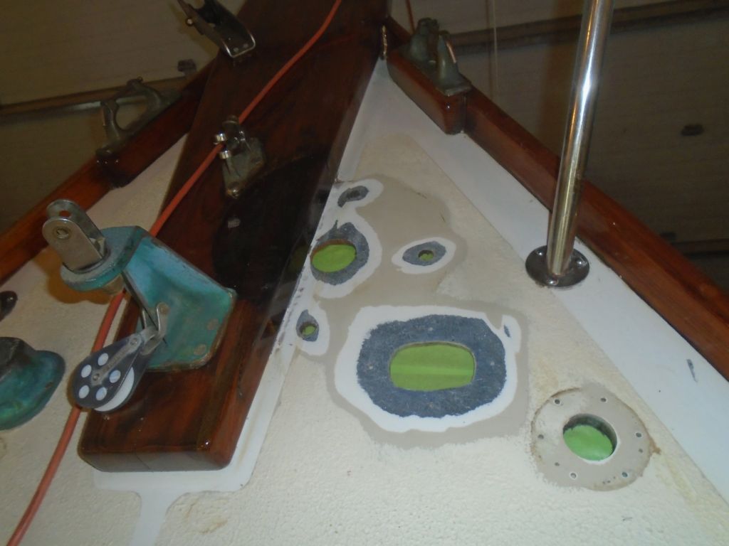
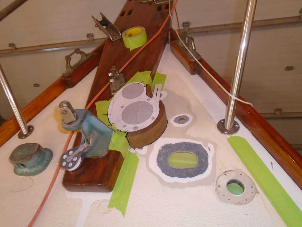
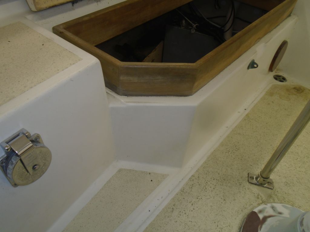
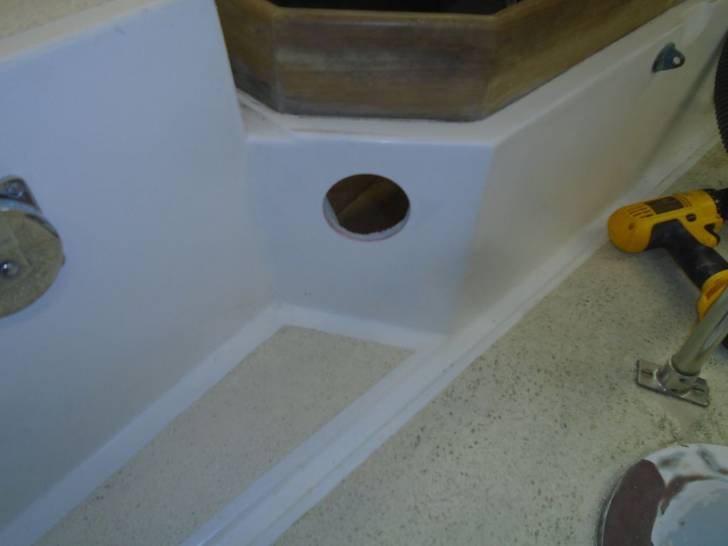
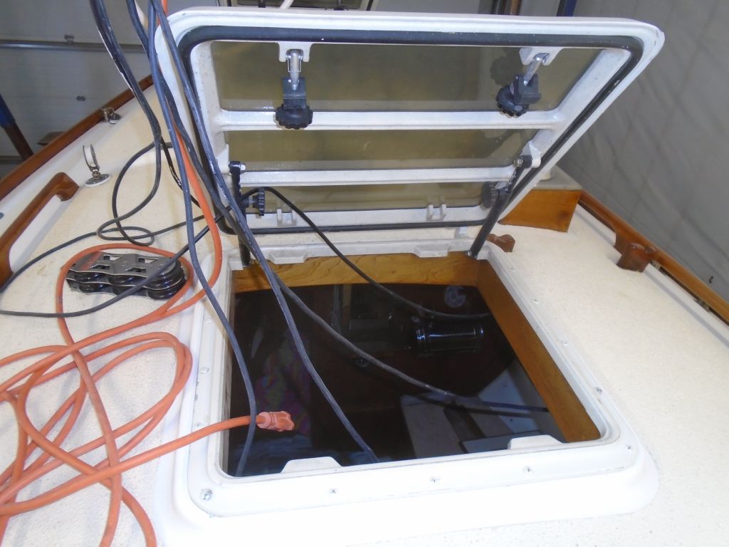
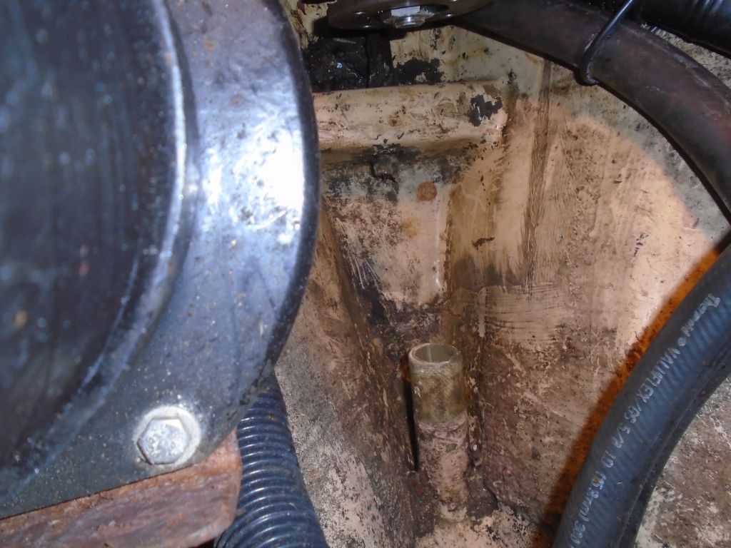
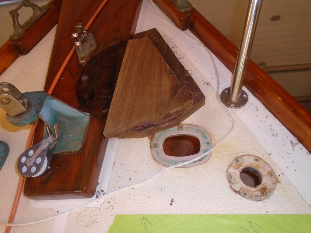
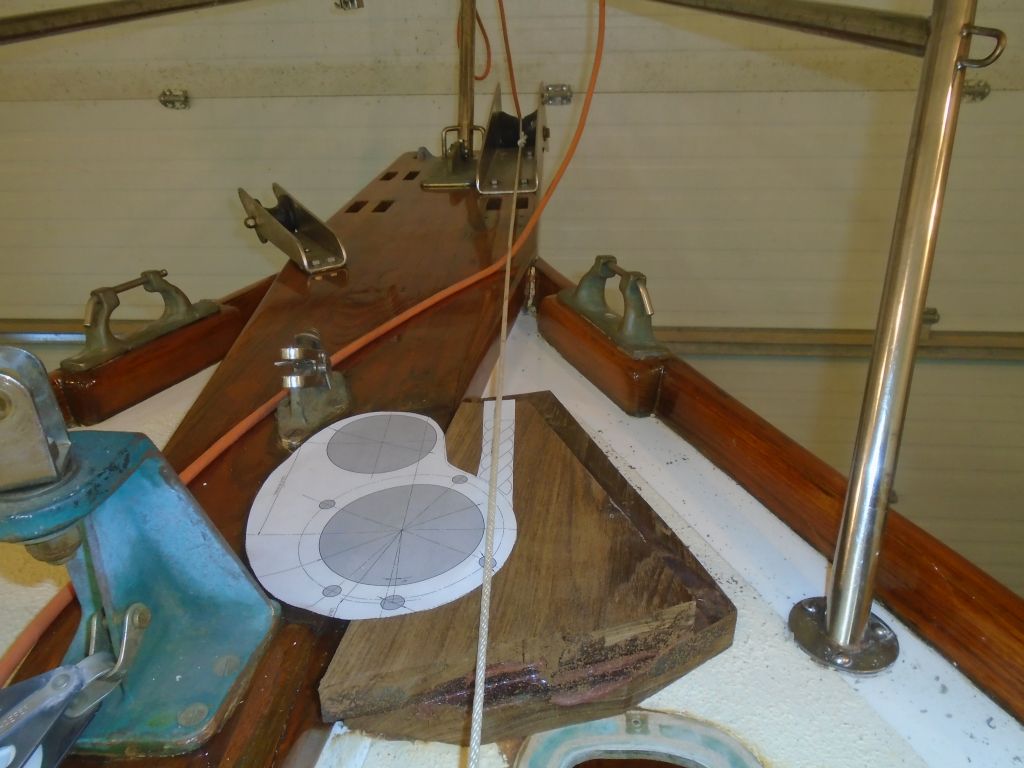
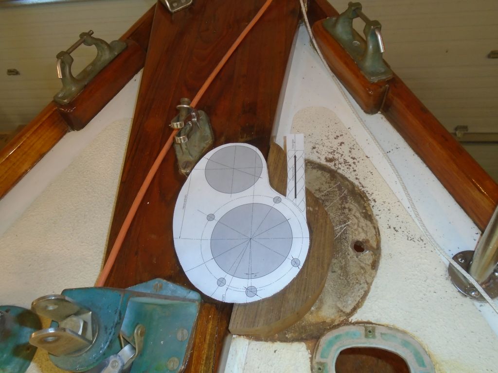
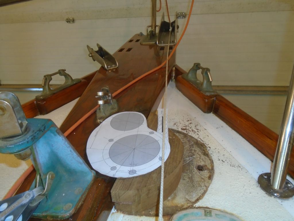
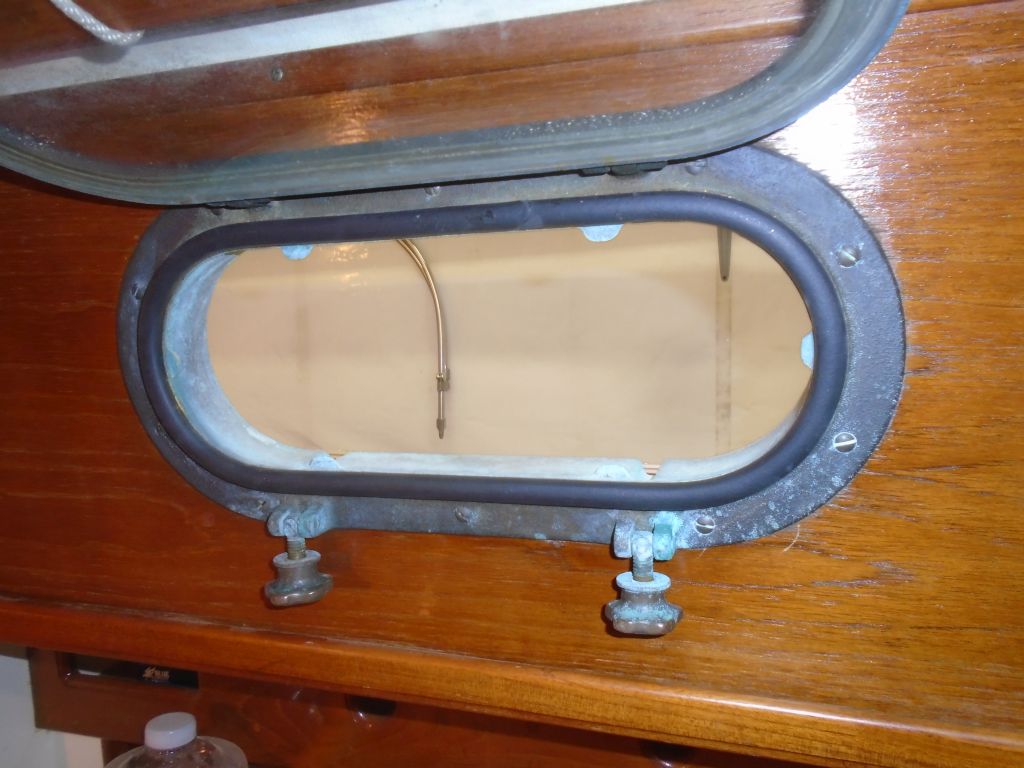
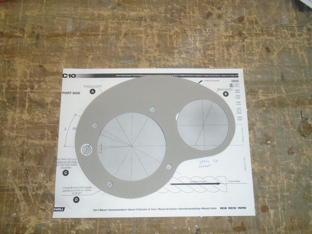
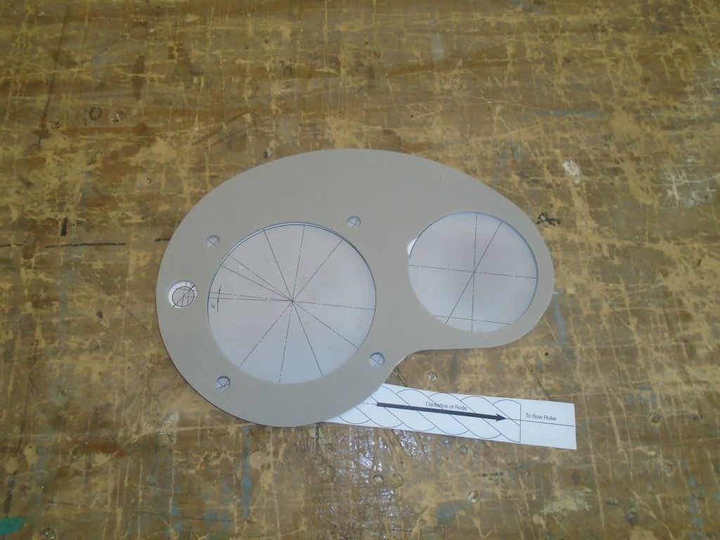
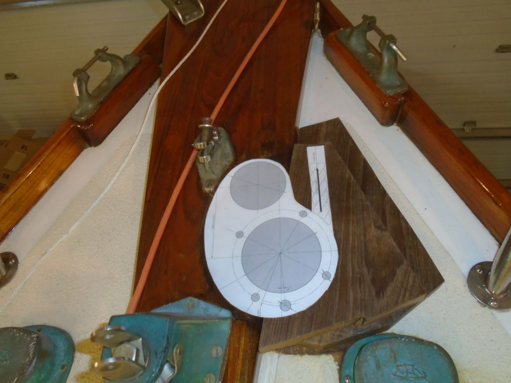
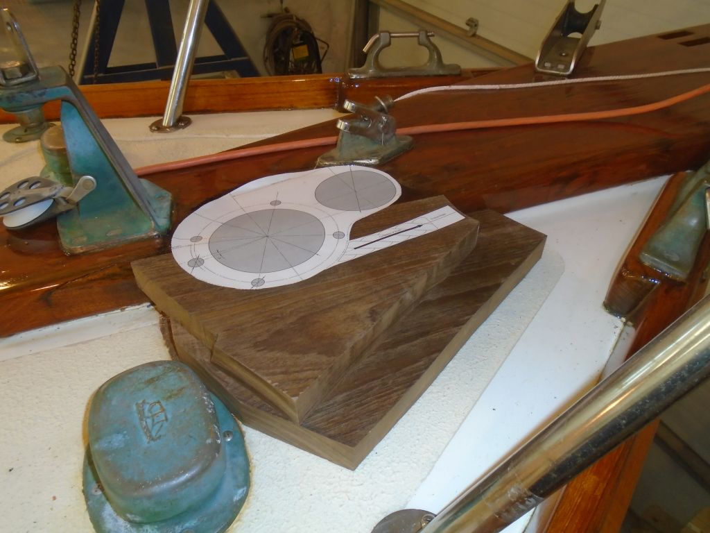
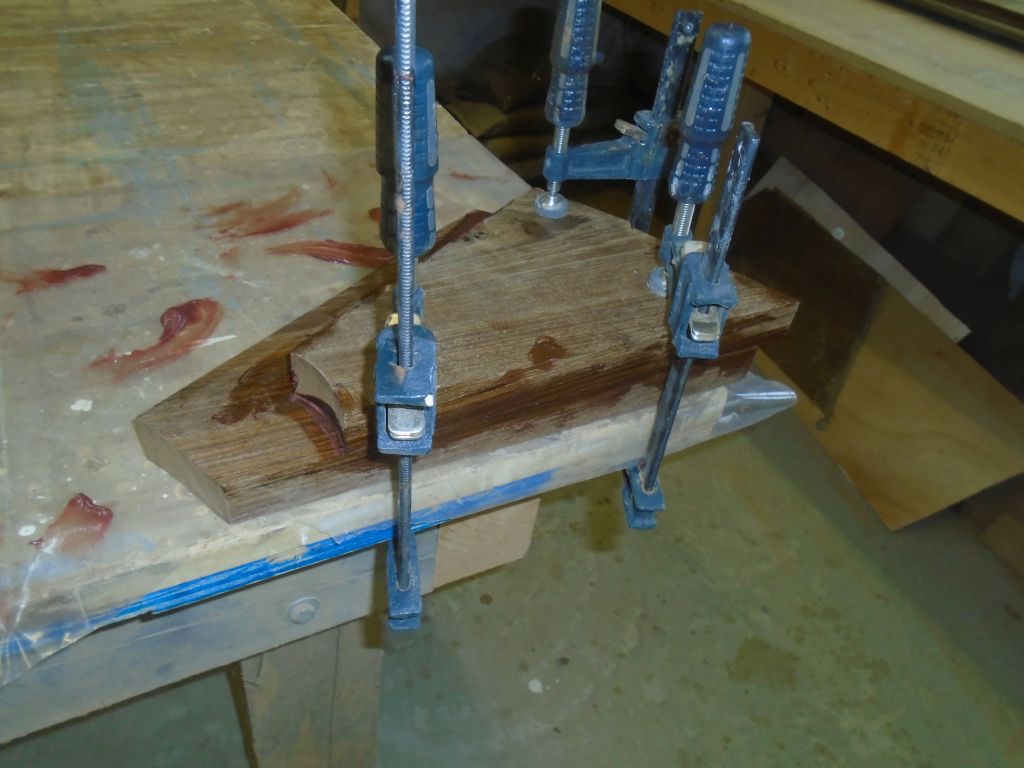
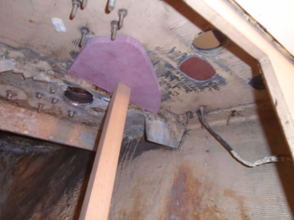
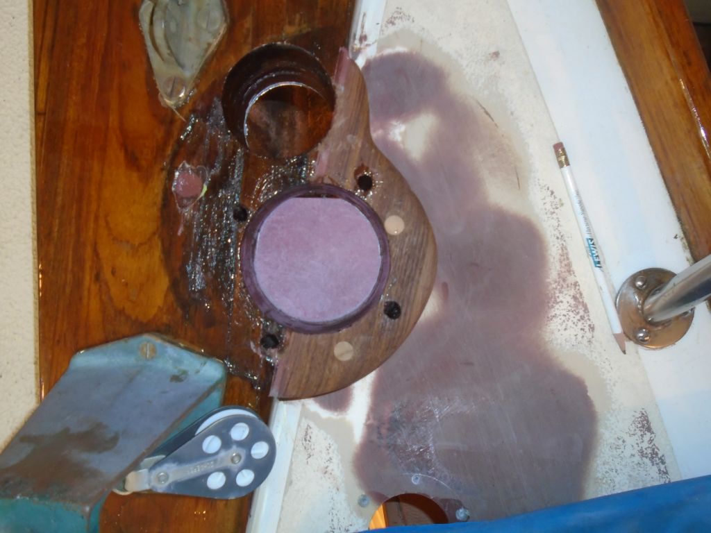
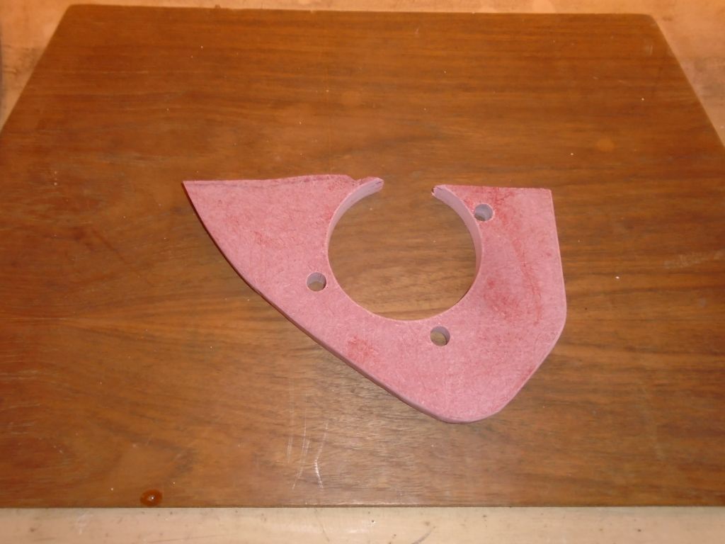
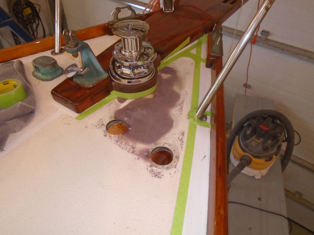
To better support the windlass and spread any loading across a larger area of the deck, I elected to prepare and install a fiberglass backing plate belowdecks.  With various existing installations to work around, I started with a piece of 3/4″ prefabricated fiberglass sheet and, after rough-trimming it to fit within the allotted space, pressed it temporarily into place with a stick to hold it so I could go on deck and mark it for the cutouts and bolt holes, which I cut down on the bench.

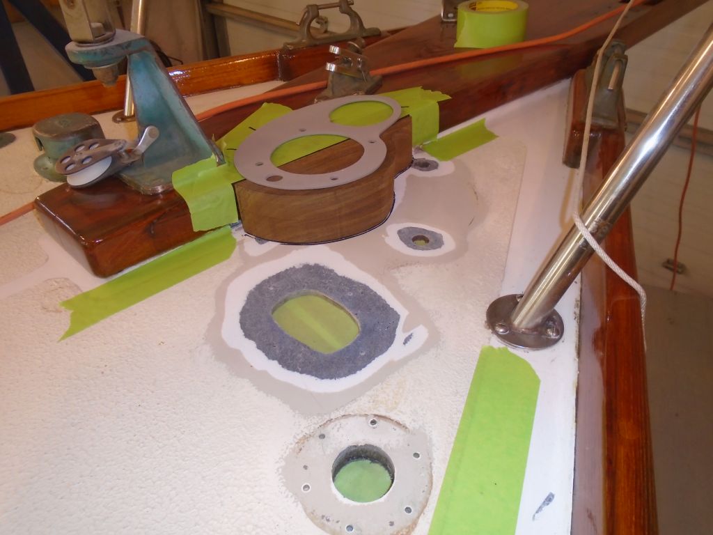
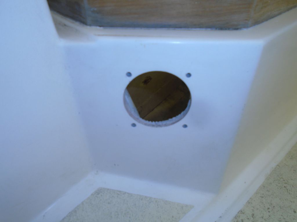
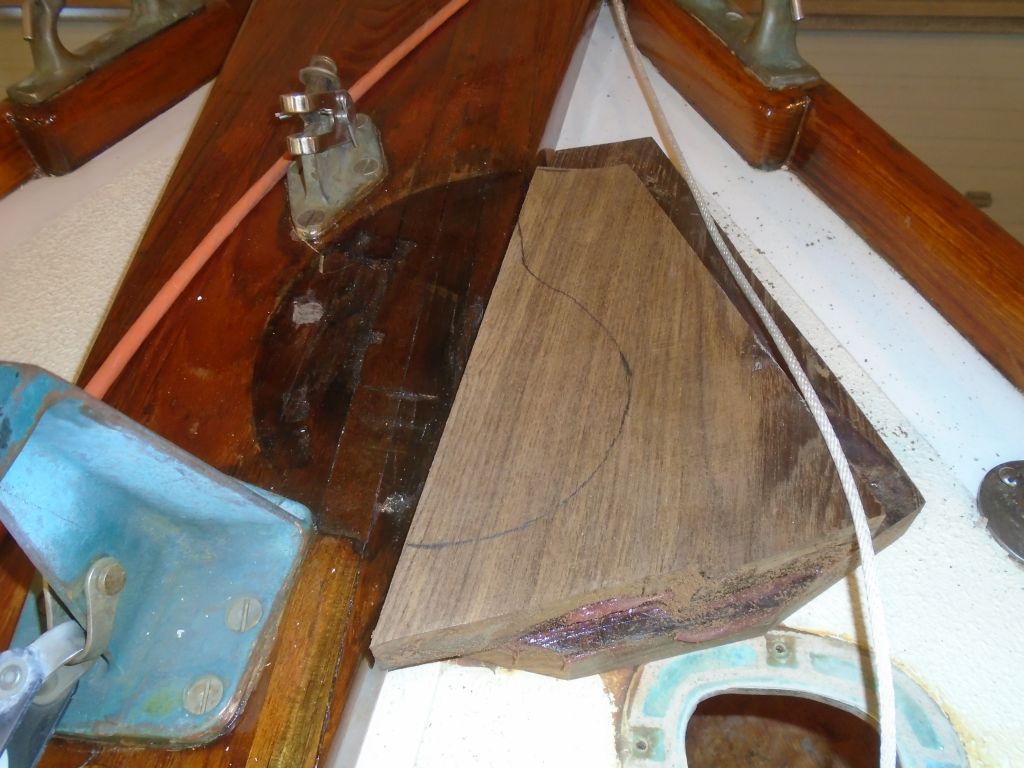
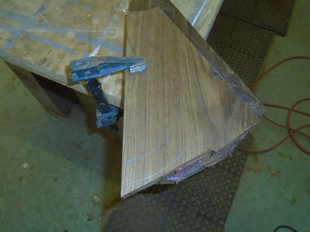
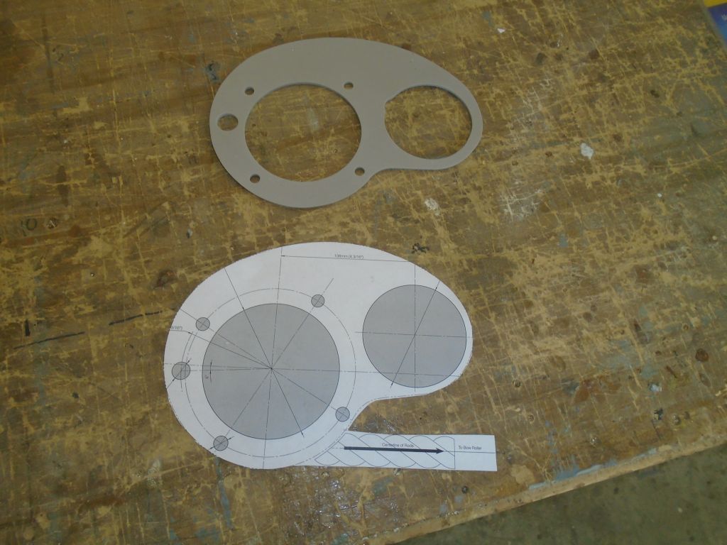
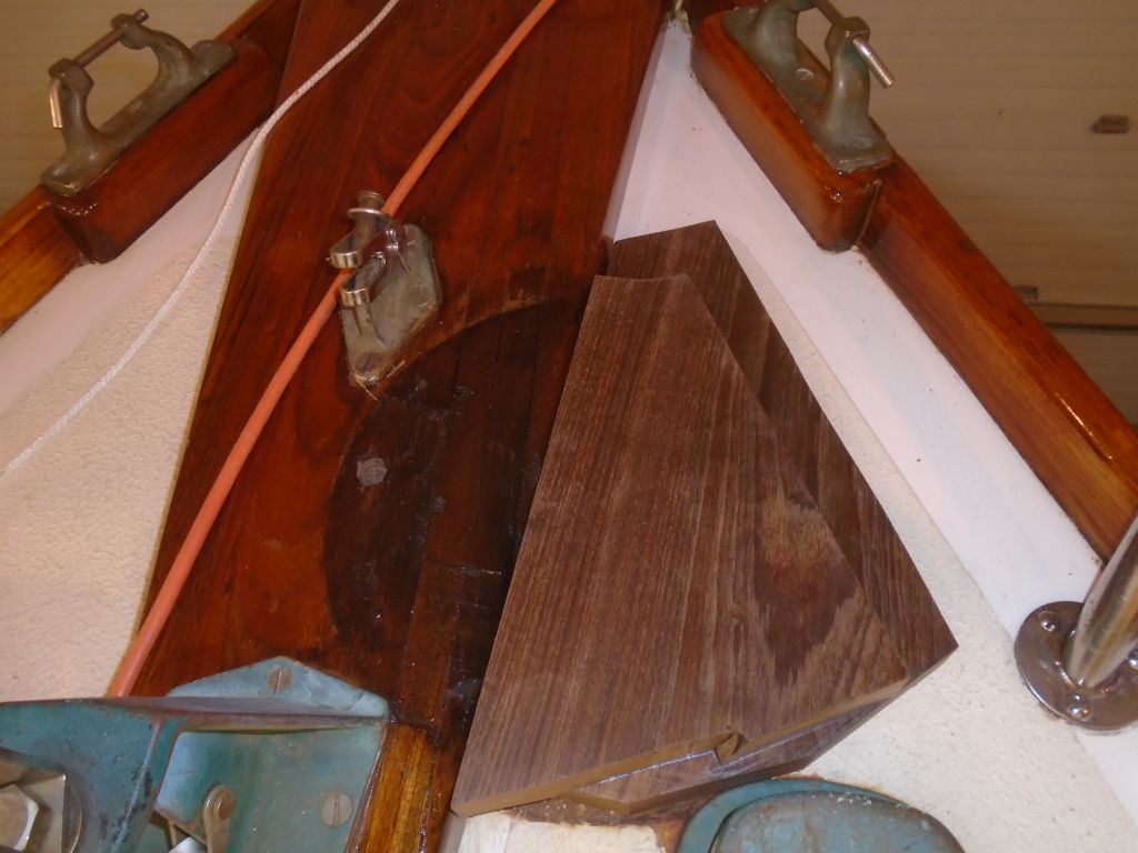
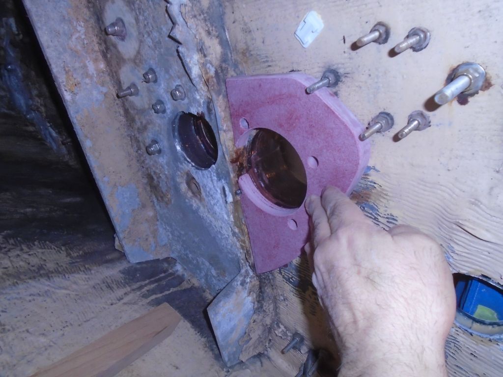
For a close fit with the built-up structure forward of the backing plate, I scribed the leading edge of the backing plate to the shape, which allowed all four windlass bolt locations  a good bearing surface.  After I removed a bit of extraneous and pre-corroded aluminum from the edge of the existing structure, the new backing plate was effectively flush to allow the fourth bolt, which was half in and half out of the backing plate, a place to rest.

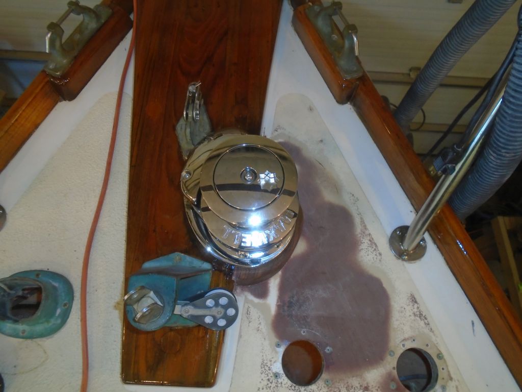
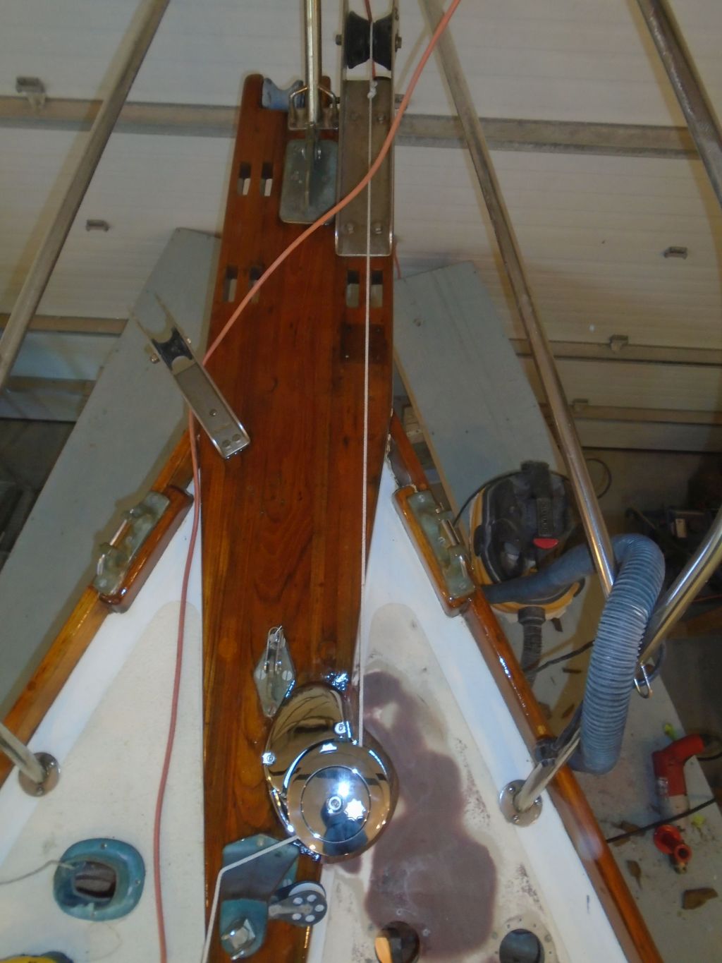
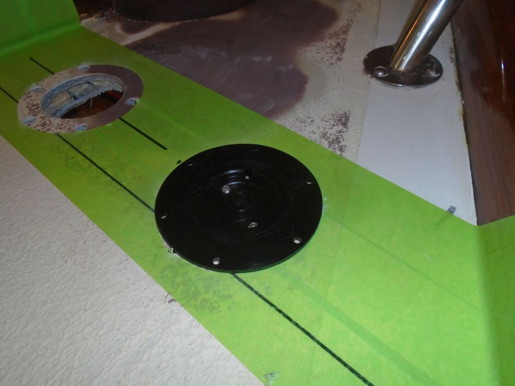
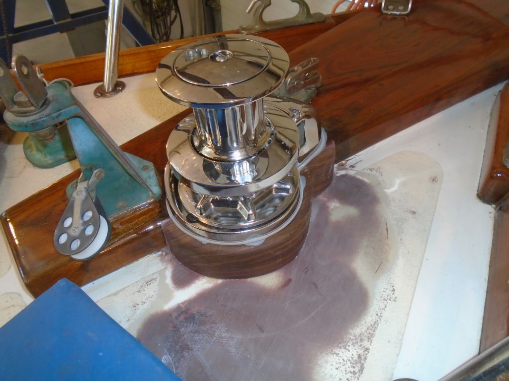
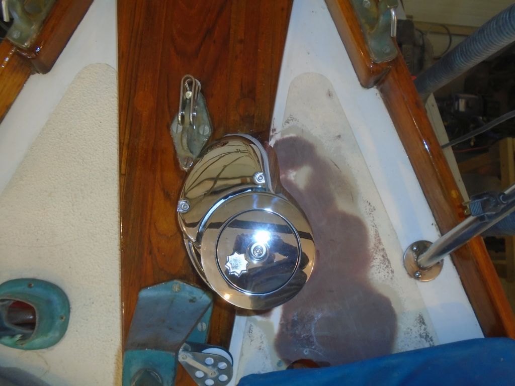
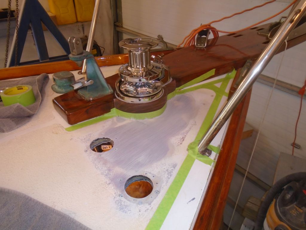
I prepared the windlass for its final installation by slipping the supplied gasket over the base.  The “knife edge” of the windlass base would probably seal the edges at the gasket fairly well, but to add some extra sealant and protection against water intrusion I added some butyl sealant around the tops of the fixing bolts and around the two large openings of the windlass base.

windlass1-21516

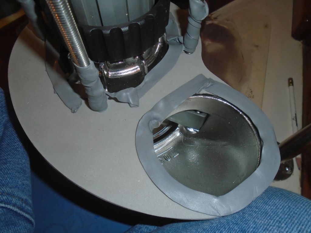
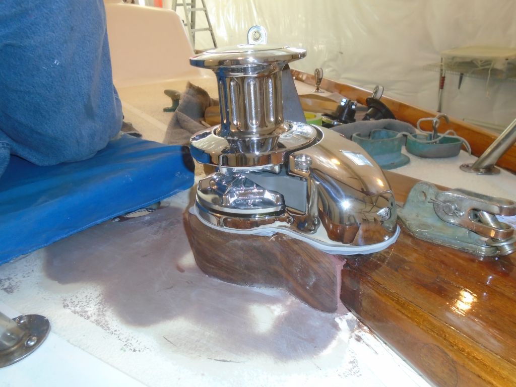
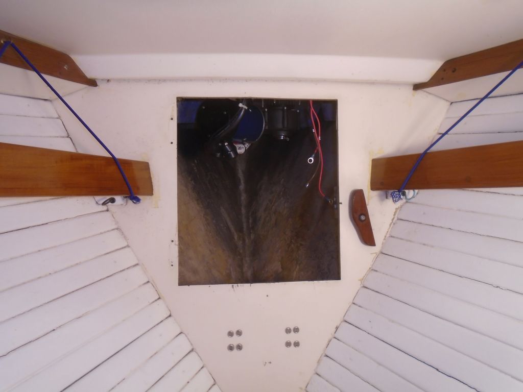
Pressing the windlass firmly into place from above–I had to push hard to get the butyl around the bolts to squeeze into the holes, which was a good thing–I moved below to install the backing plate, fender washers, and nuts, and I tightened the bolts in turn to pull the windlass securely into place.  As I’d hoped, back on deck the gasket looked well-compressed below the windlass base, and some of my butyl had squeezed out as well.

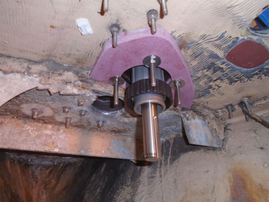
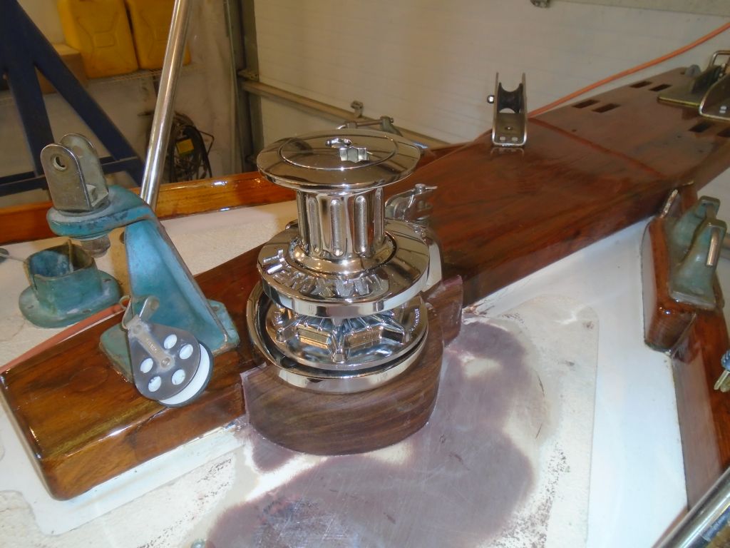
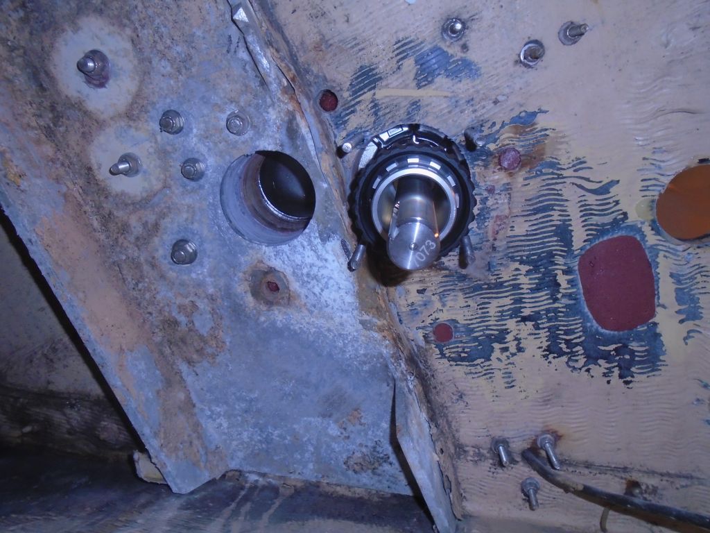
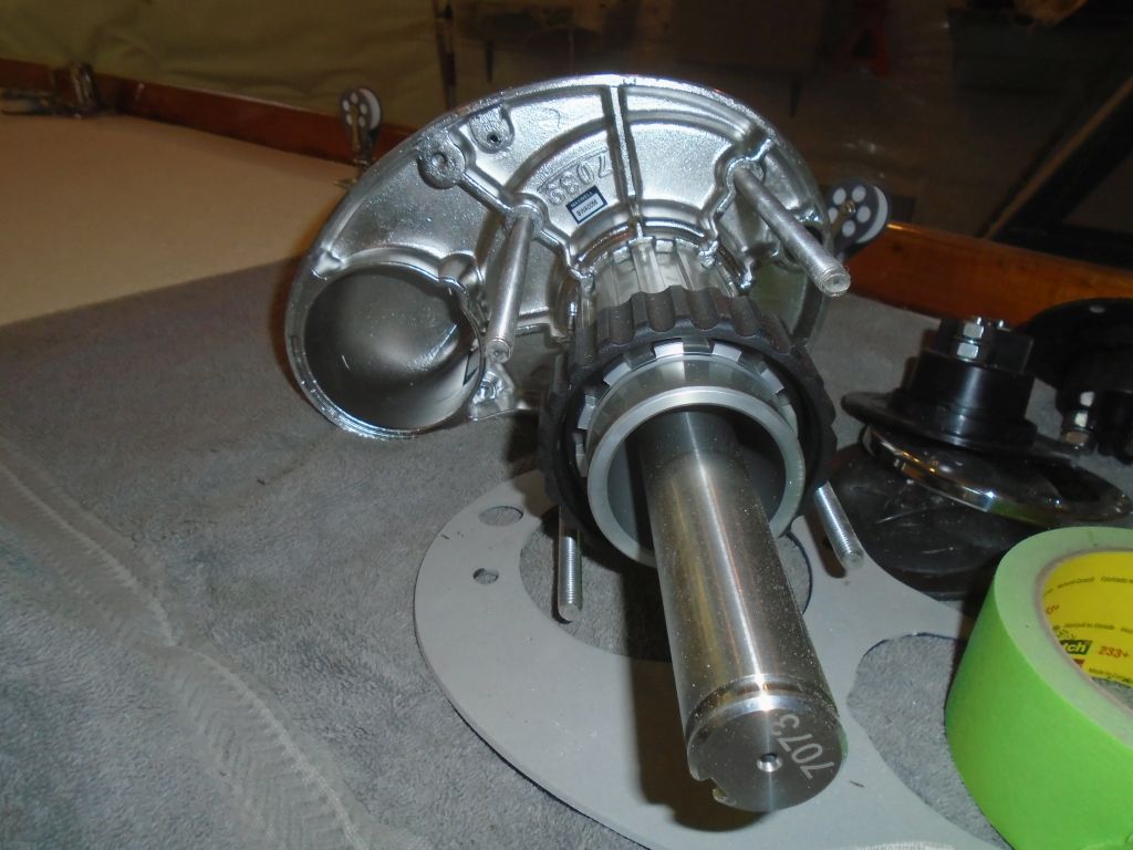
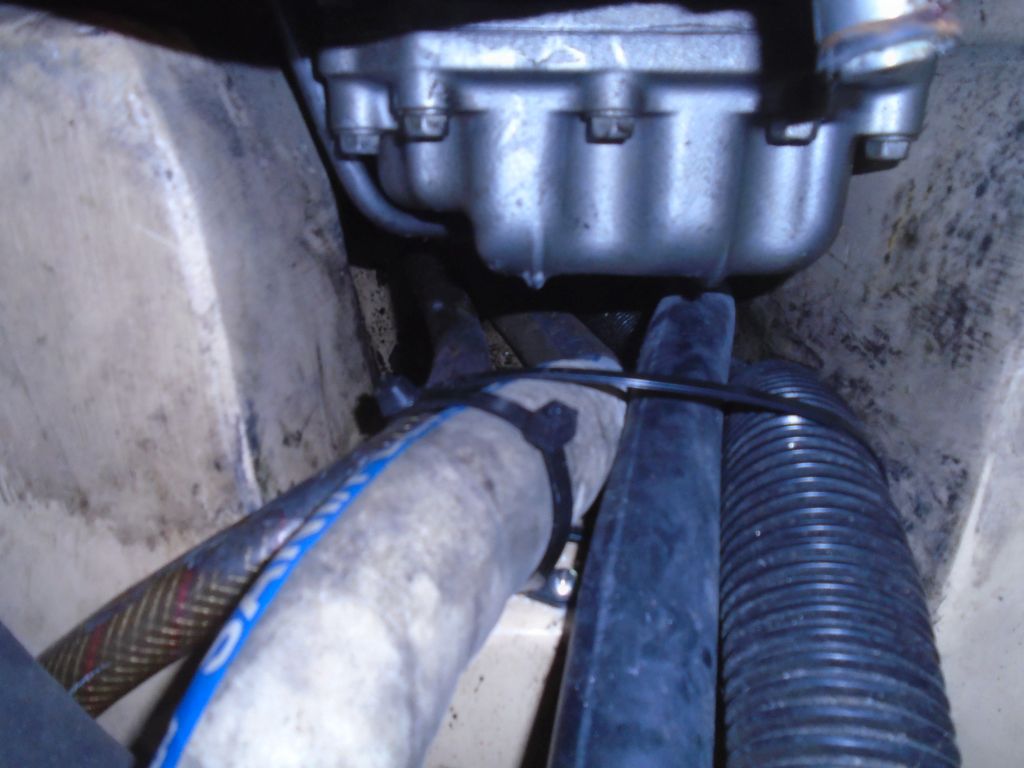
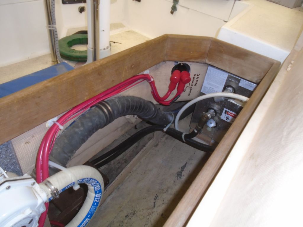
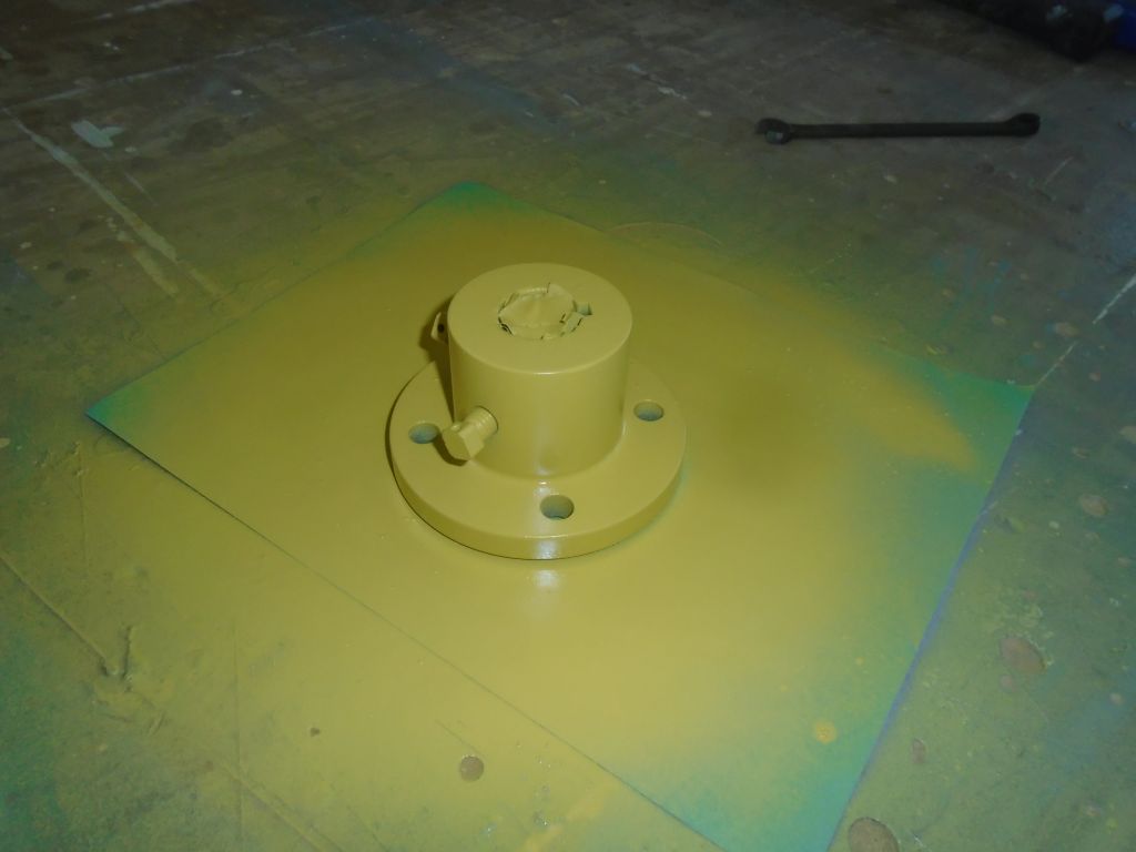
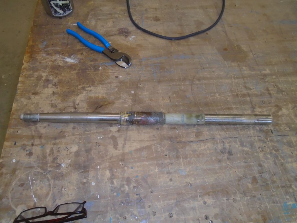
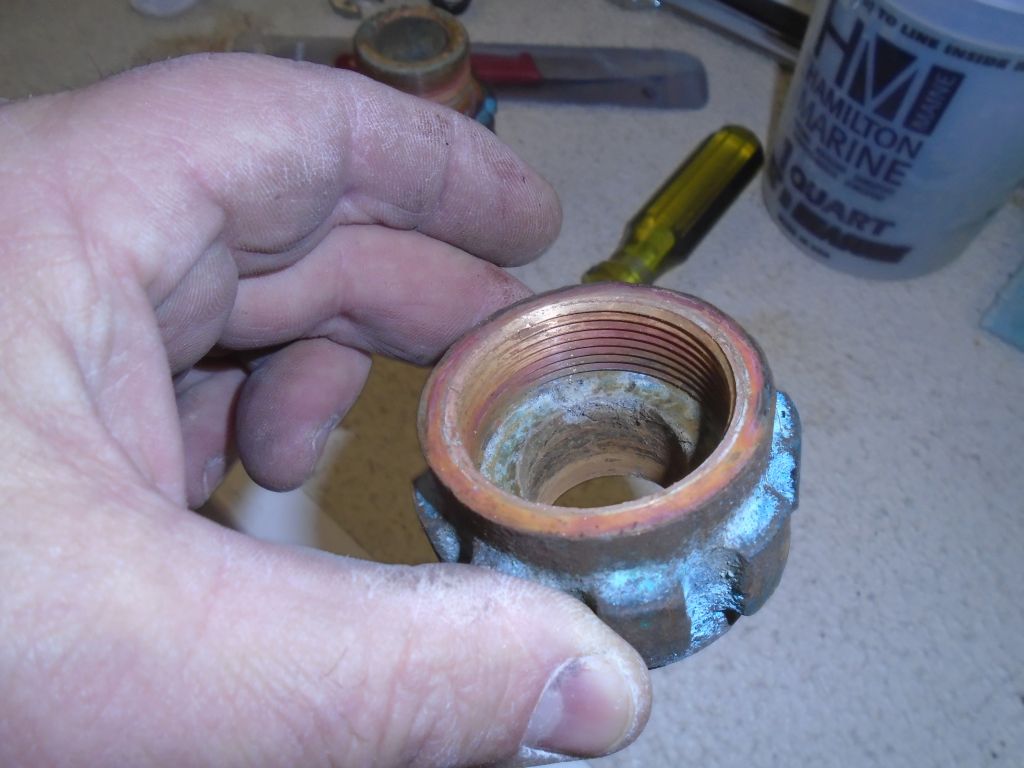
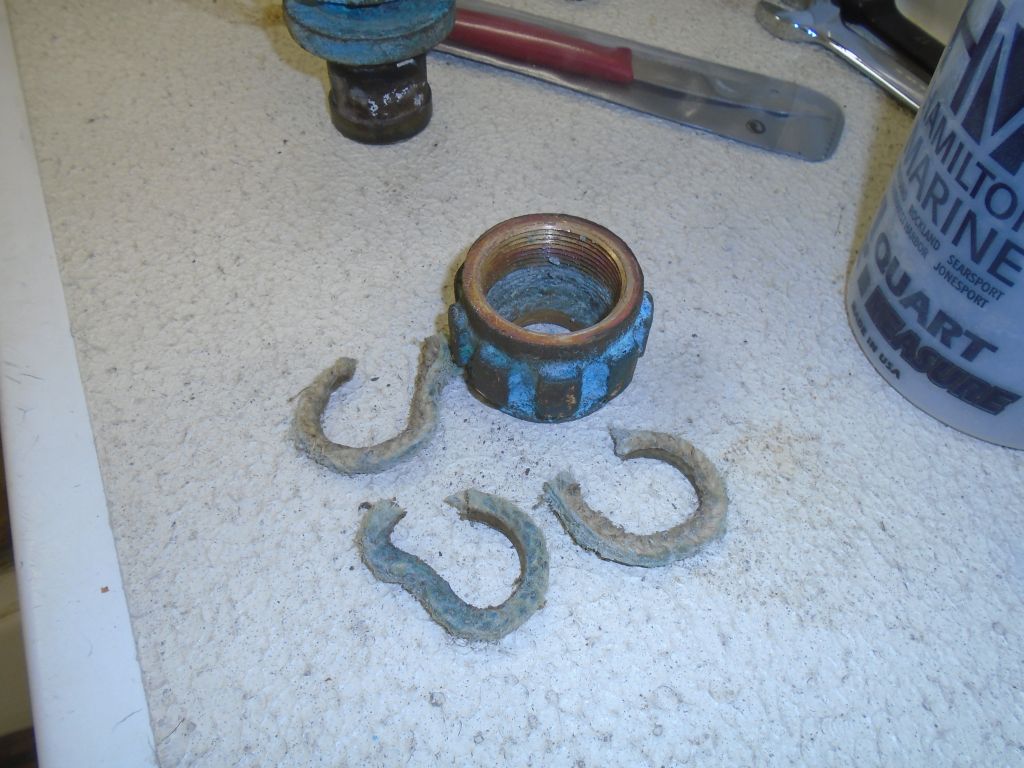
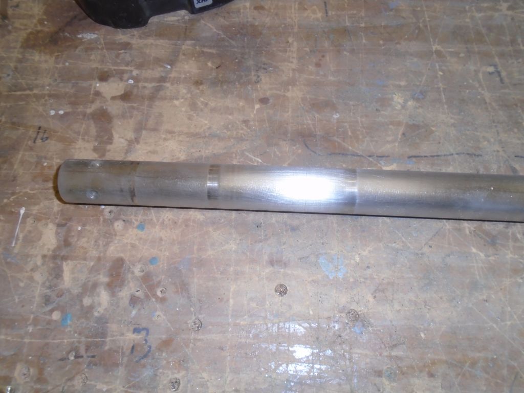
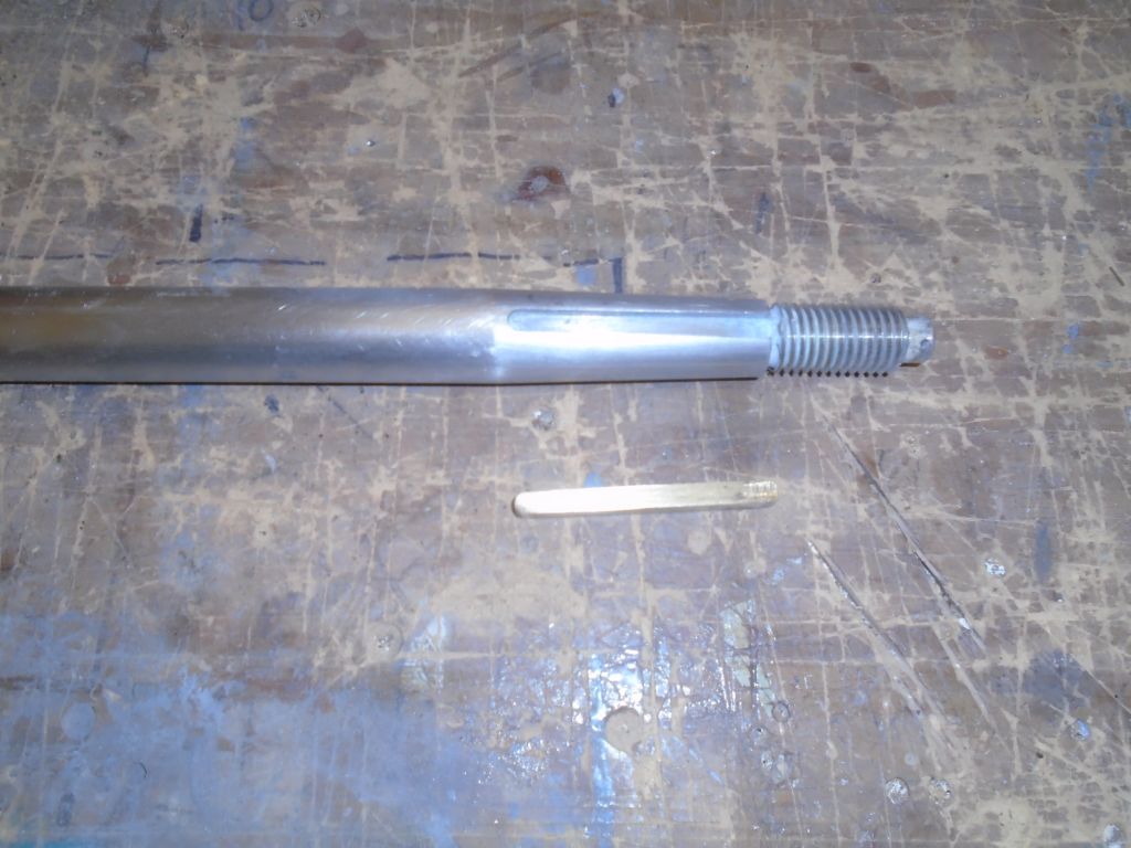
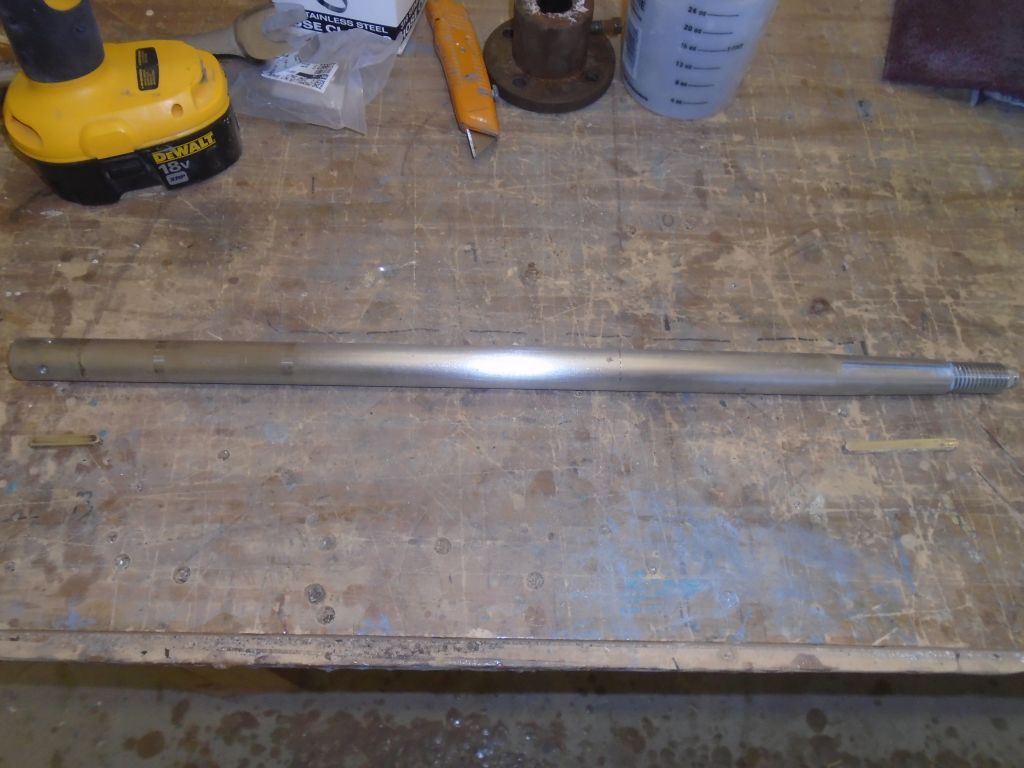
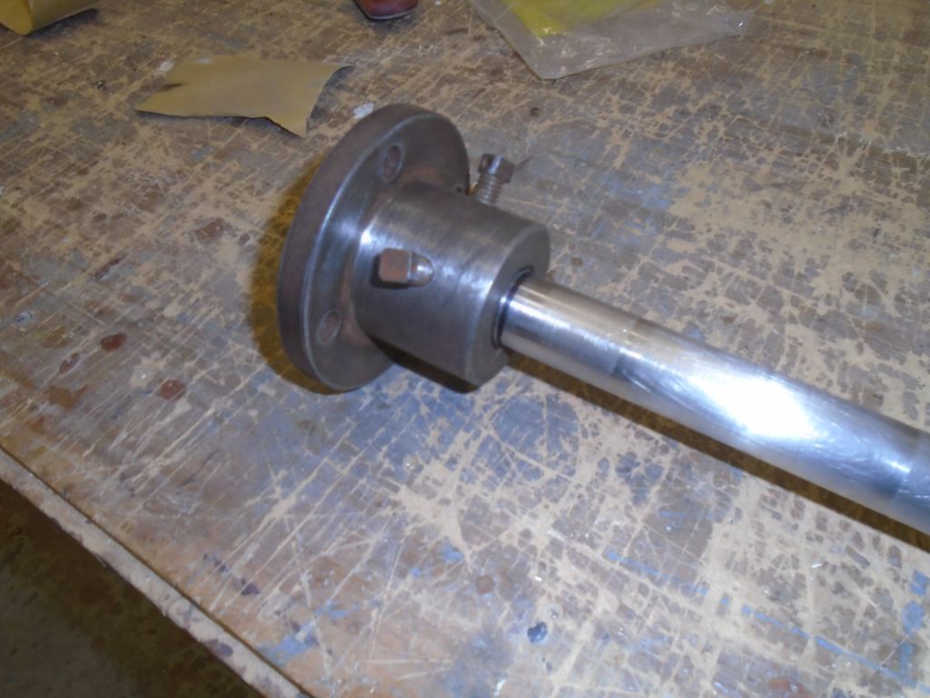
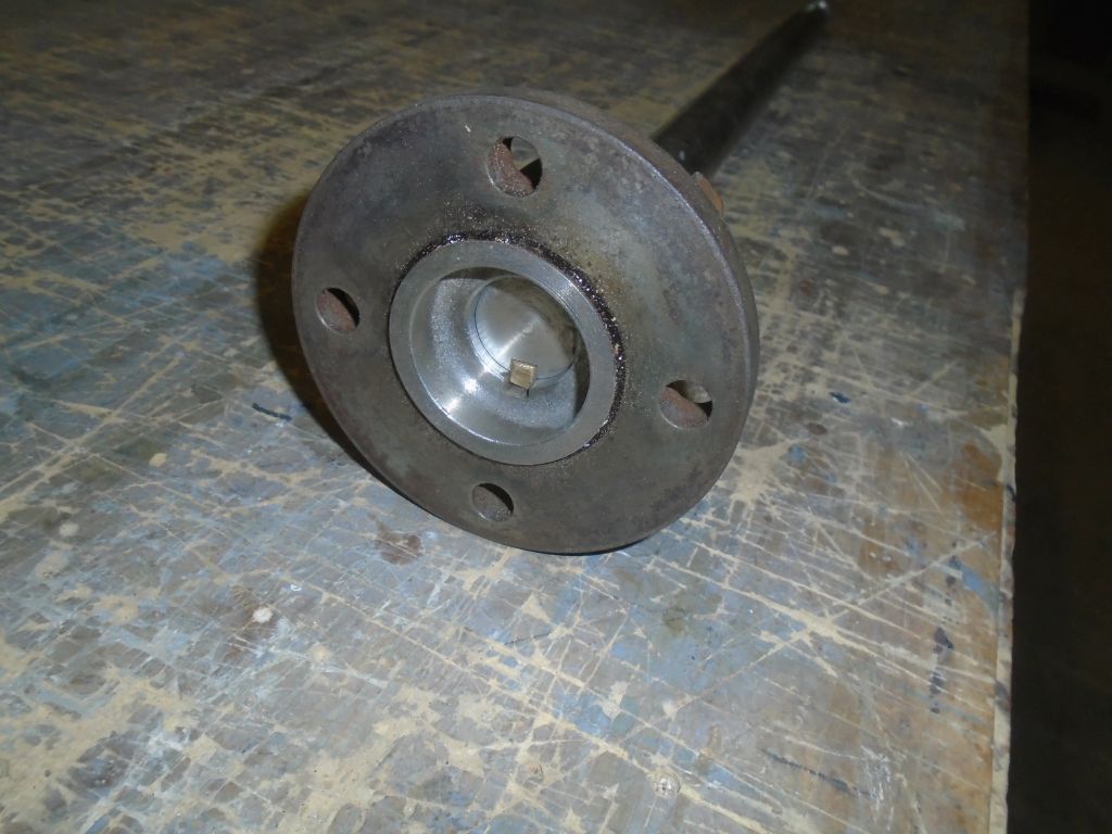
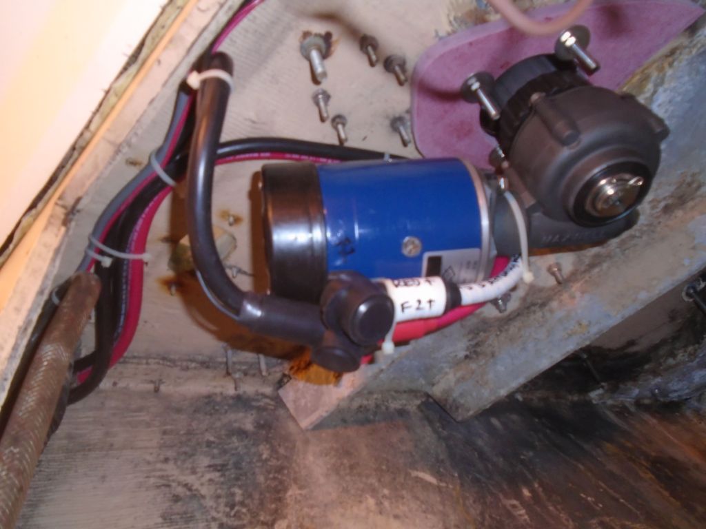
On paper, the windlass setup, with its threaded collar and shaft, castellated gearbox, and separate electric motor, looked fairly well thought-out from an installation standpoint, and so it turned out to mainly be.  To begin the installation, I applied good waterproof grease to various areas, as directed, including the shaft and key, inside of the gearbox, castellated interface, and the threads to accept the large fixing nut on the shaft, as well as the motor shaft, bolts, and mounting flange,

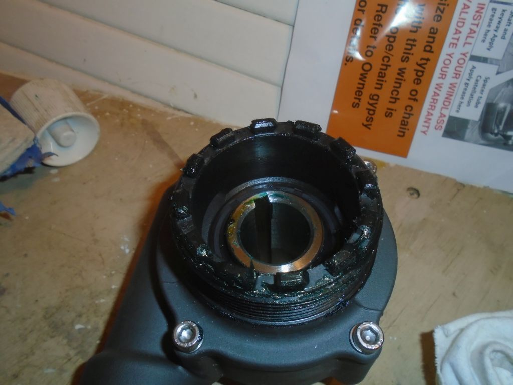
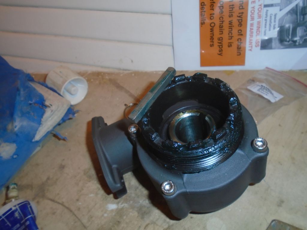
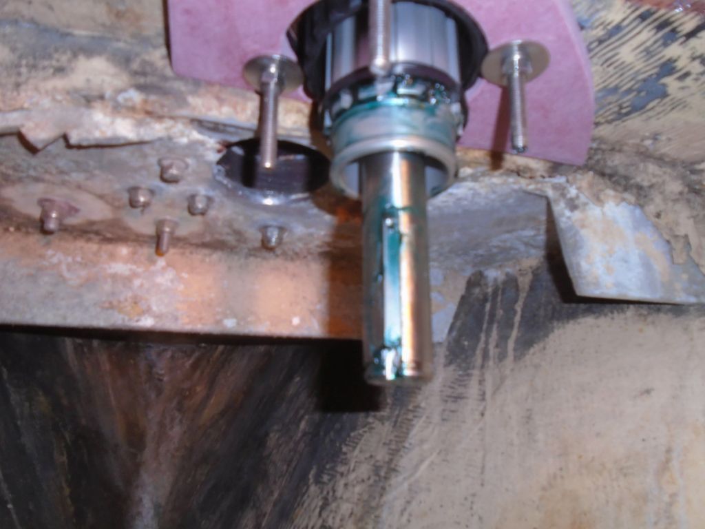
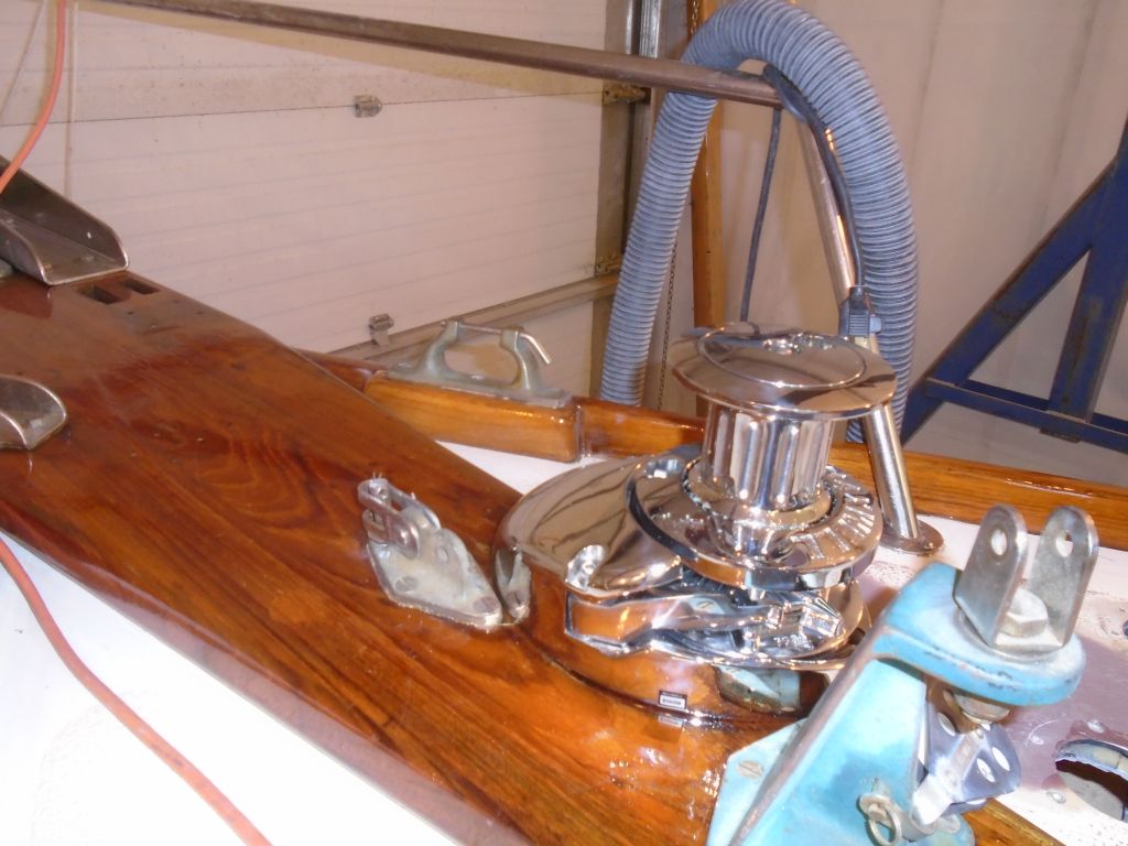
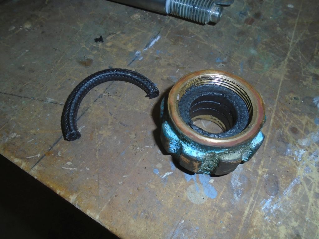
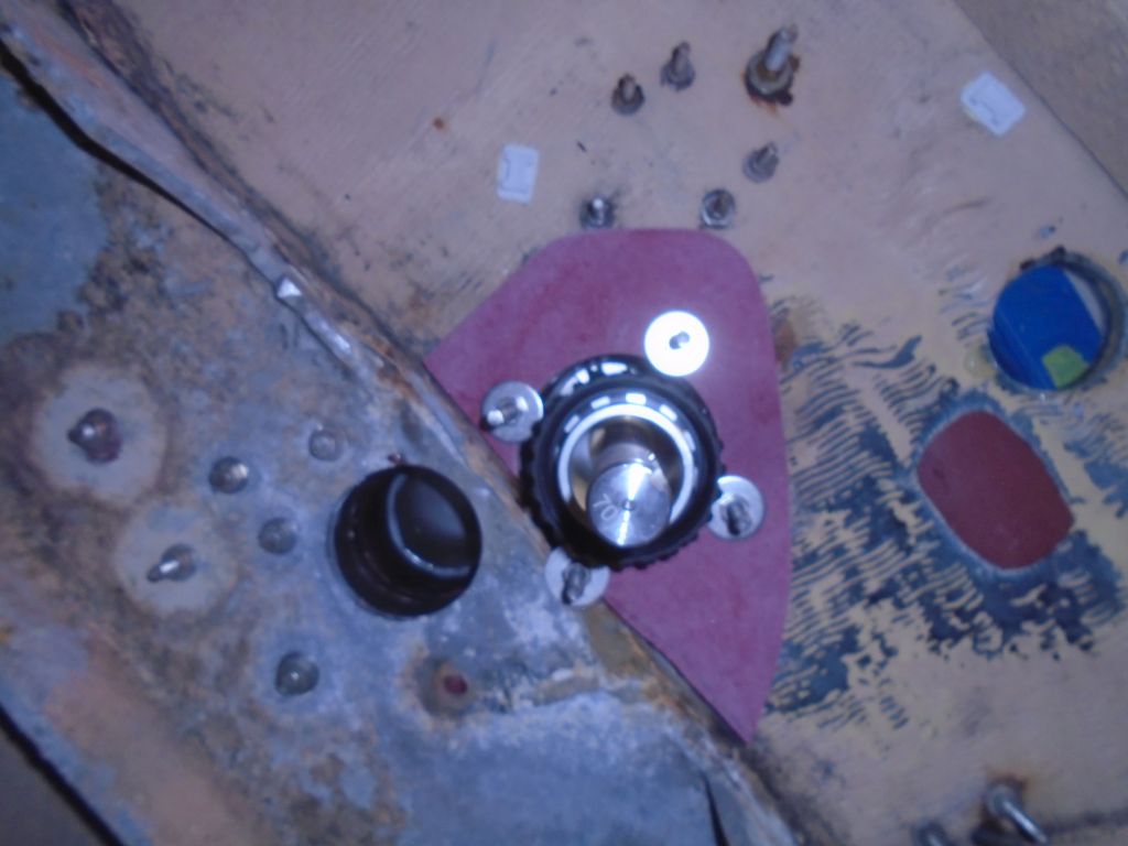
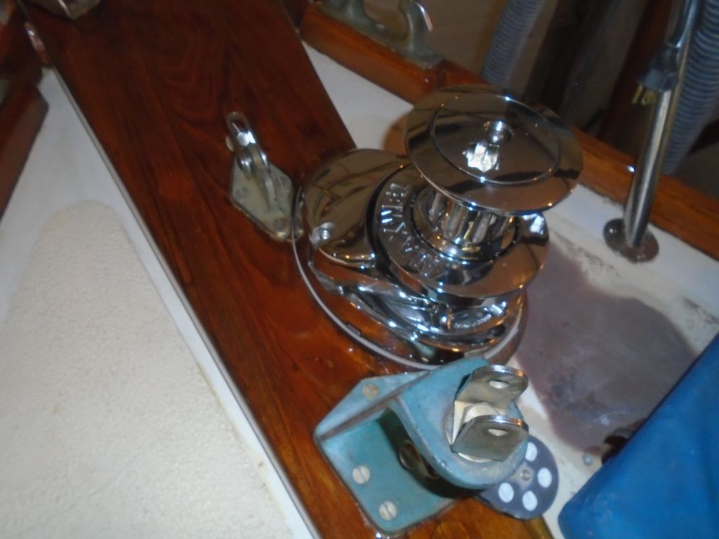
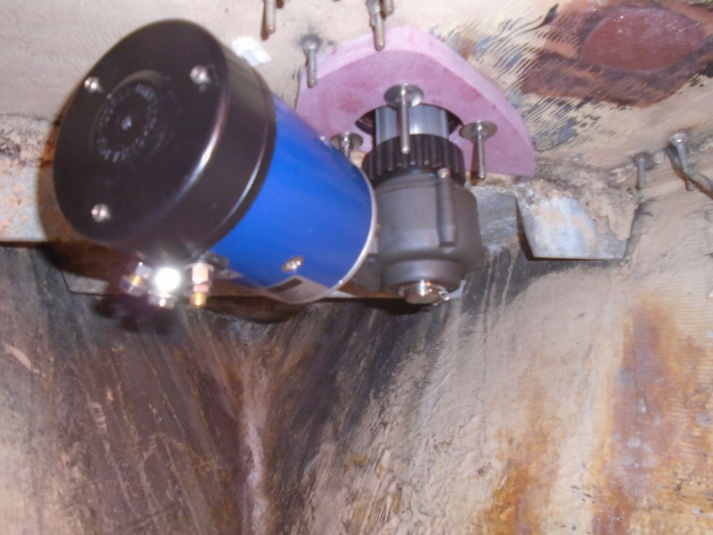
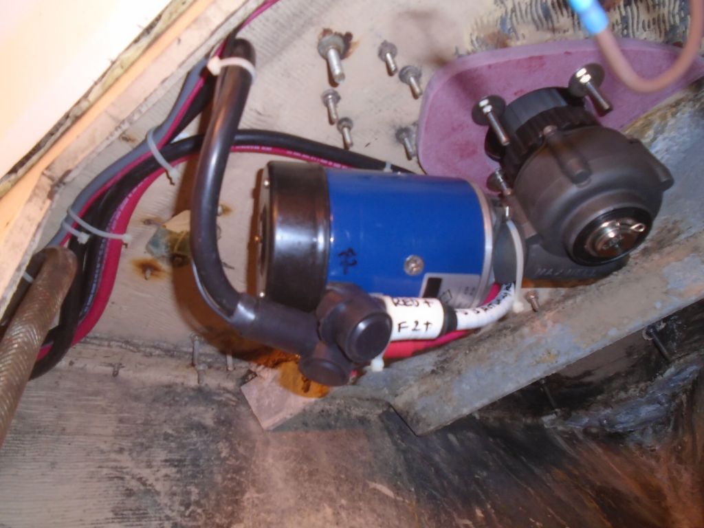
The system allowed easy positining of the gearbox and motor assemblies for various situations, and after trying a position or two I settled on facing the gearbox and electric motor aft and to port, which offered the best access, kept it out of the way of the windlass chain pipe, and away from the two foot switches to keep access there as good as possible also.  The notched end of the gearbox housing fit into corresponding notches on the shaft housing, with a st ainless key to secure the windlass shaft within.  To secure the gearbox, the large plastic nut from the housing simply threaded hand-tight over the gearbox threads, with a simple clamping ring at the bottom of the shaft to secure the key within.

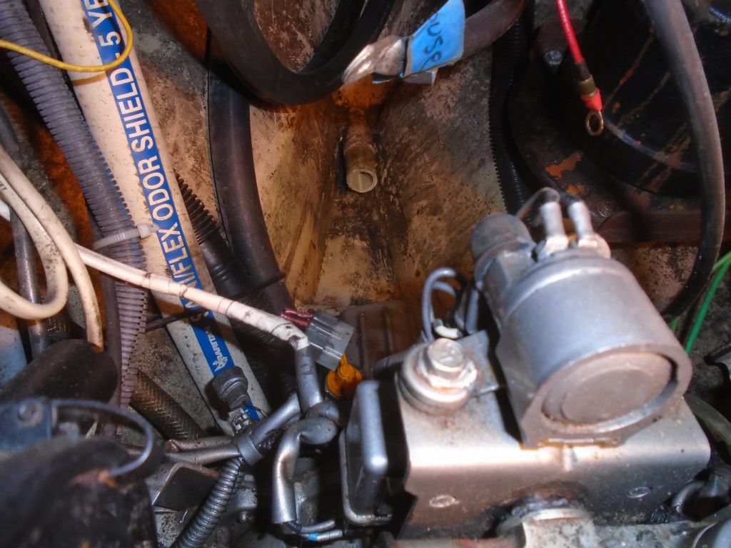
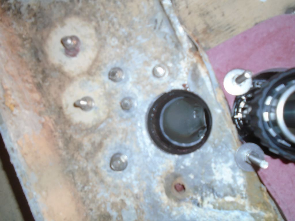
The motor was heavy, and with limited arm and shoulder access into the chain locker its initial positioning took a little wrestling till I figured out the best way to hold it in place–and lined up with the shaft–while getting the bolts started.  The two bolts threaded into the motor housing itself, so there was no need to juggle nuts and double wrenches, amd once the weight of the motor was supported it was no task at all (though I wished–as I frequently do–that manufacturers would leave enough room around bolt heads for a ratcheting box end or even a real socket and ratchet).  Yipe, yipe, yipe.

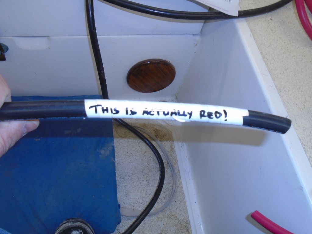
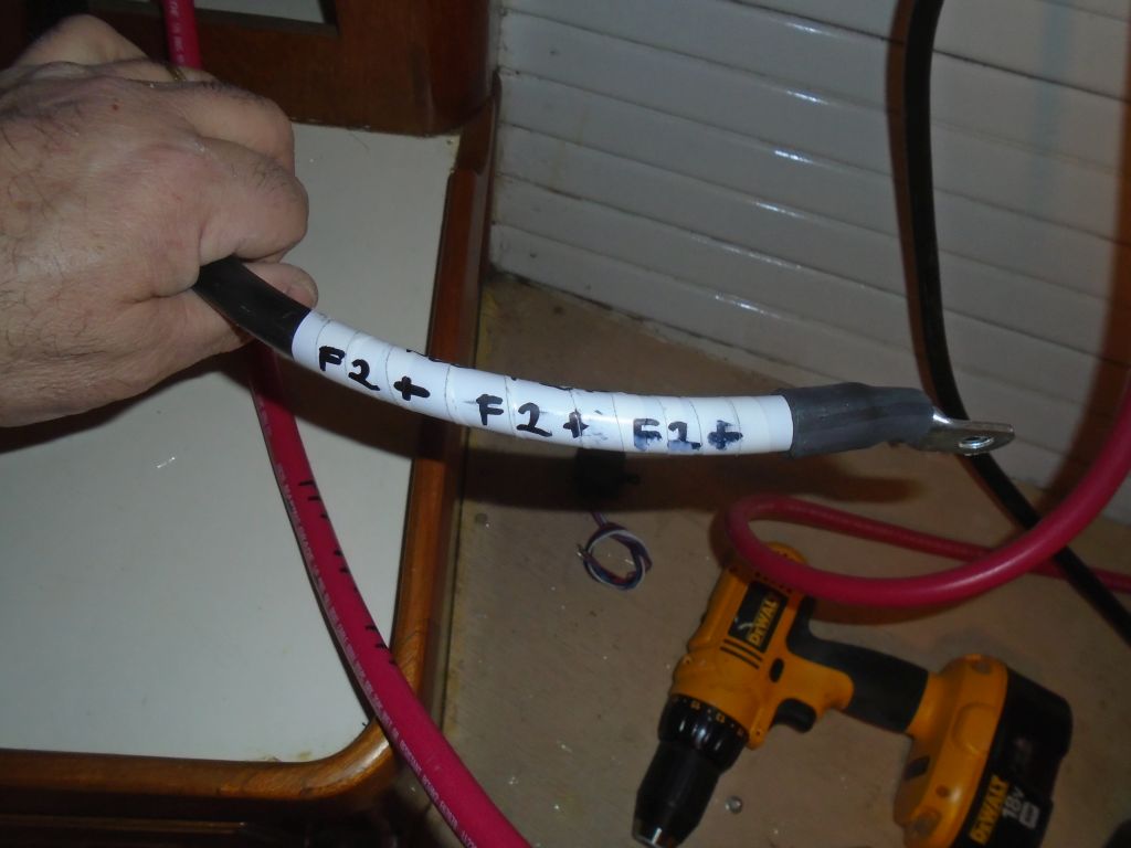
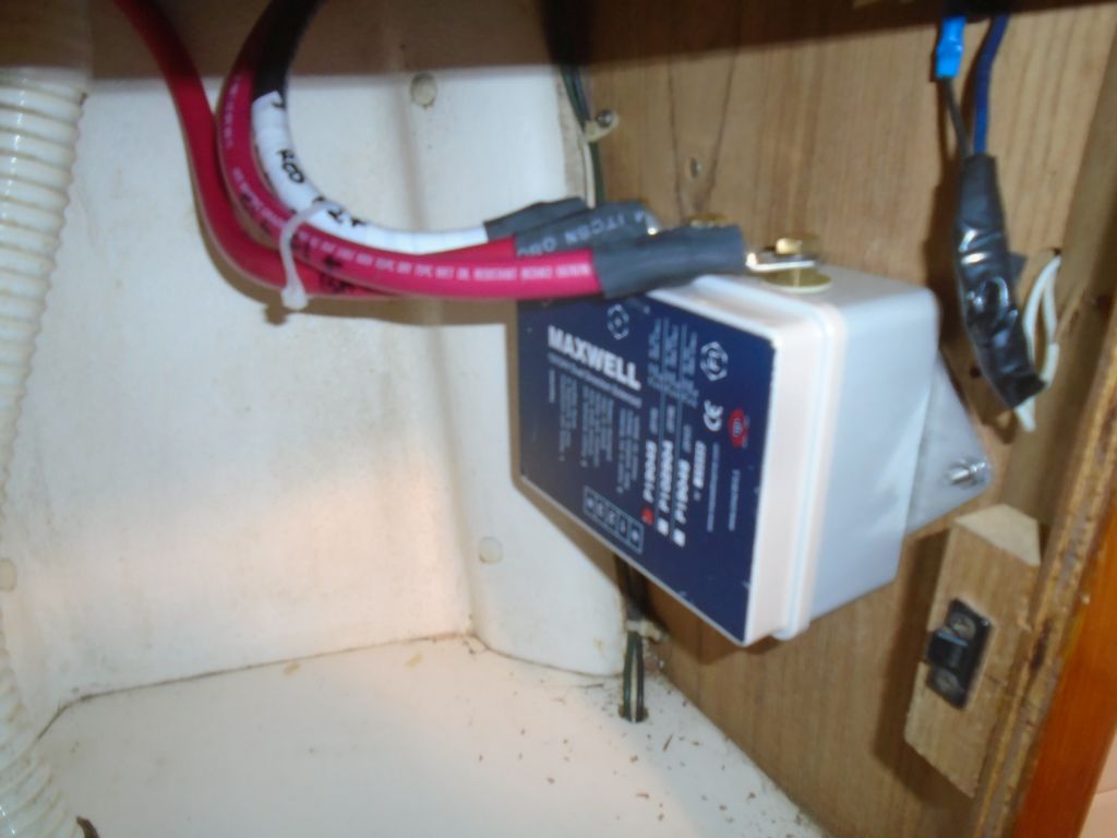
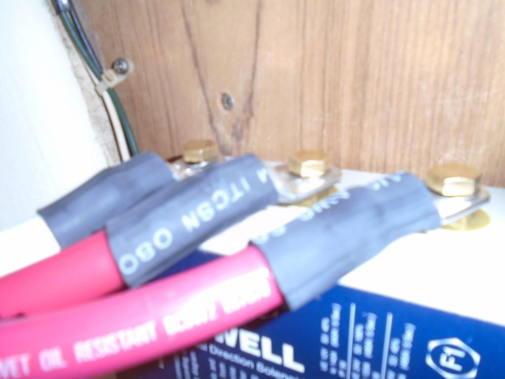
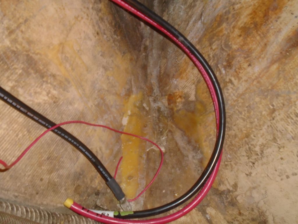
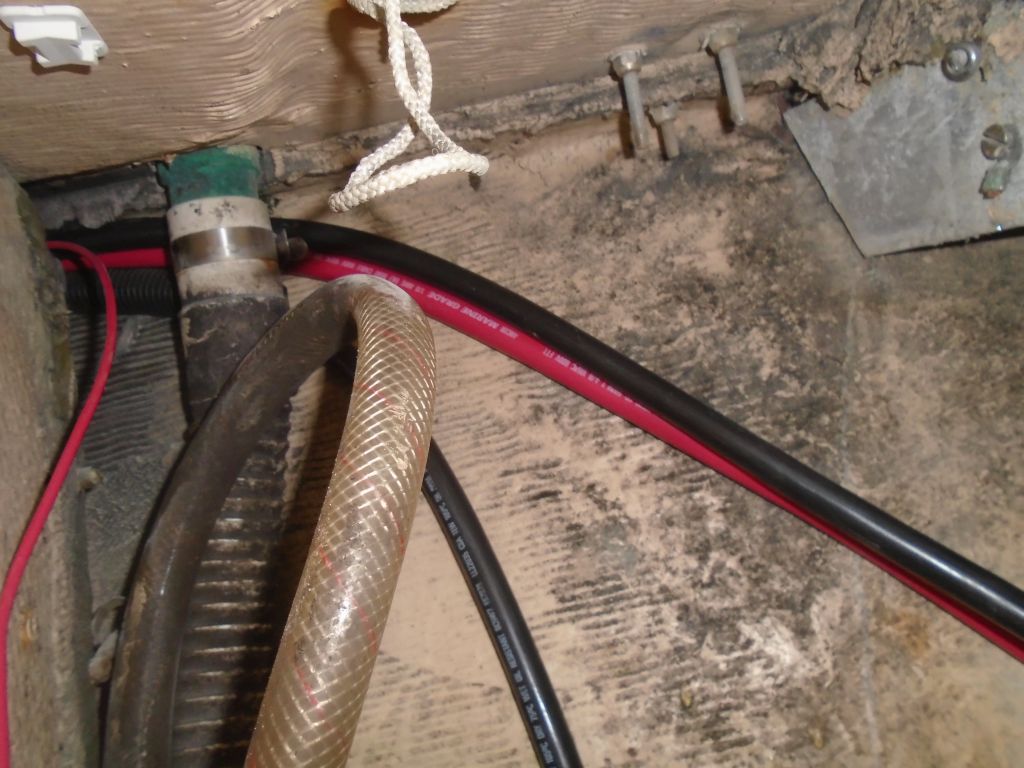
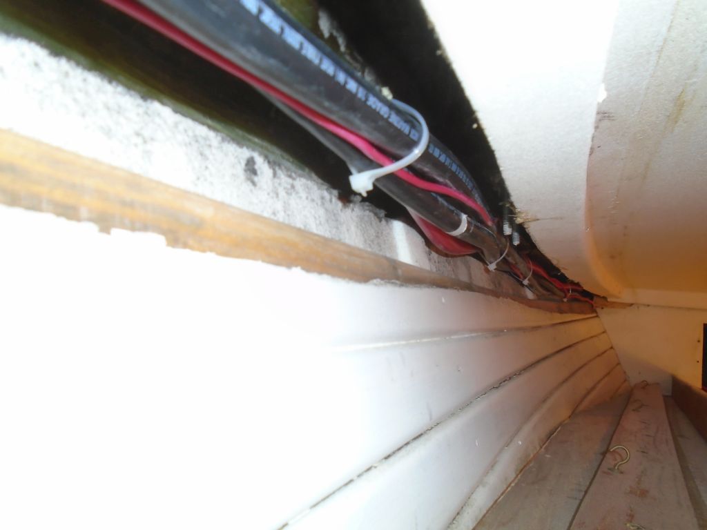
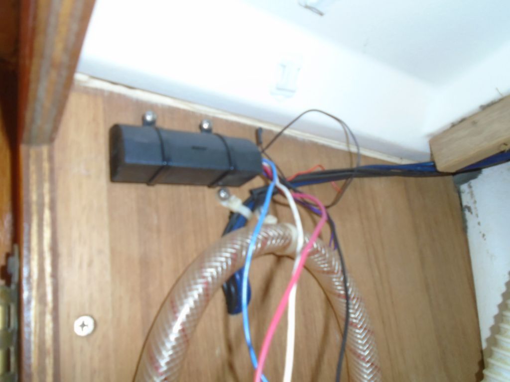
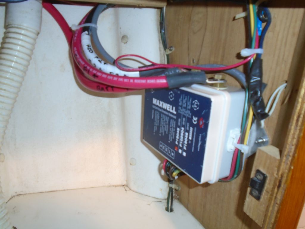
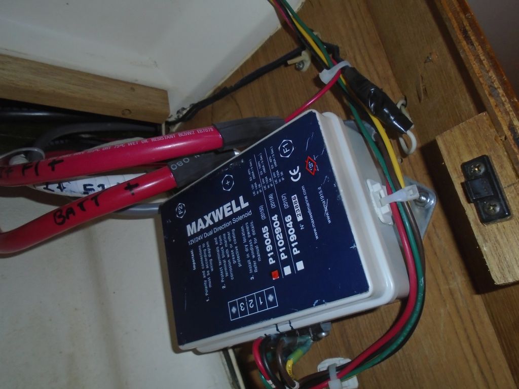
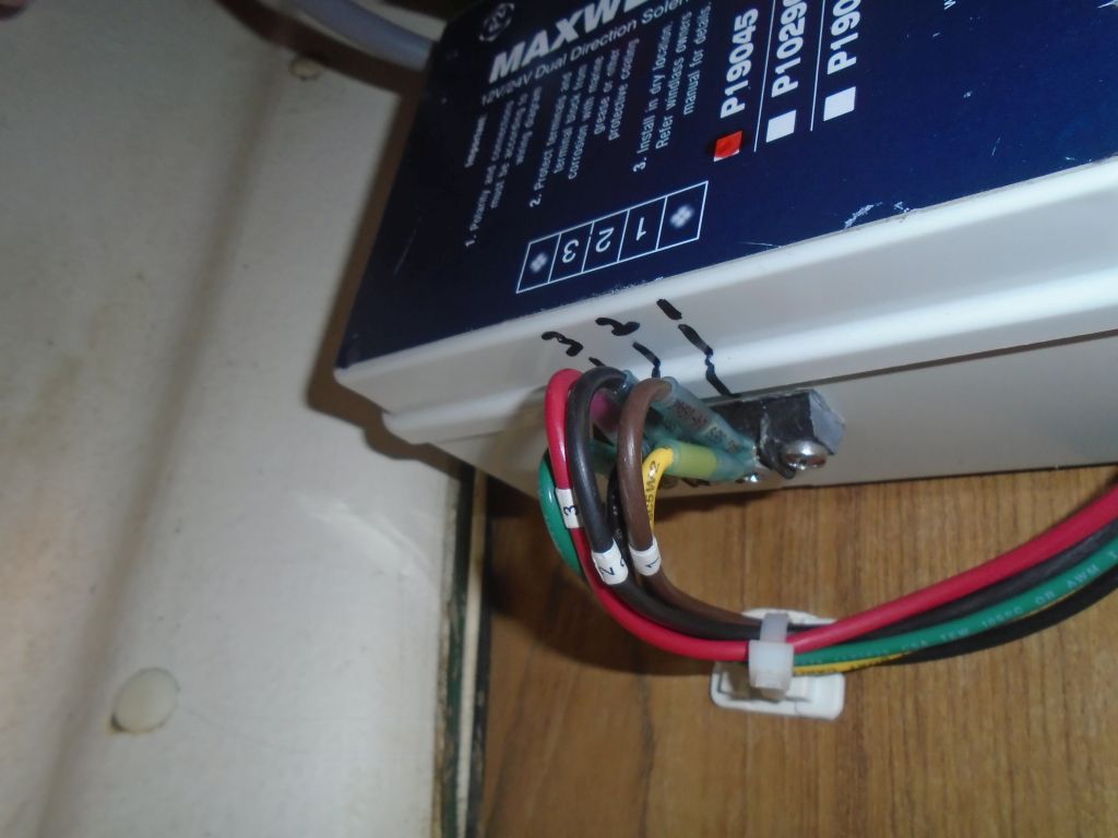
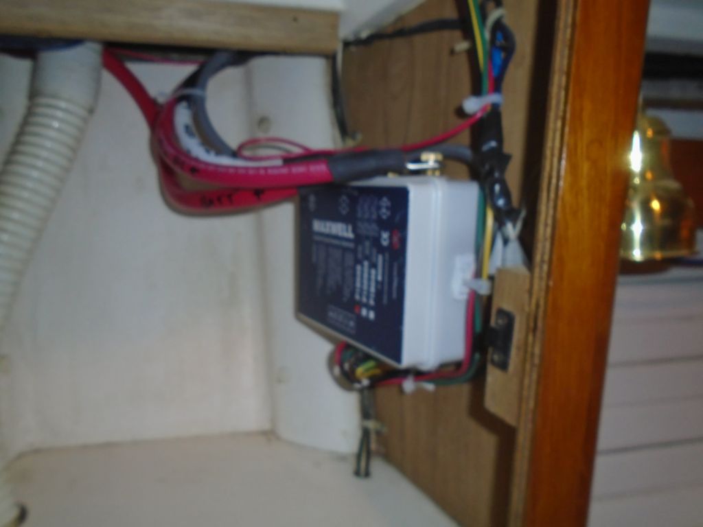
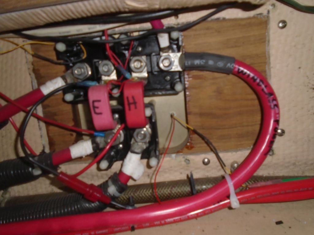
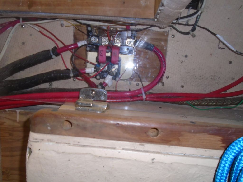
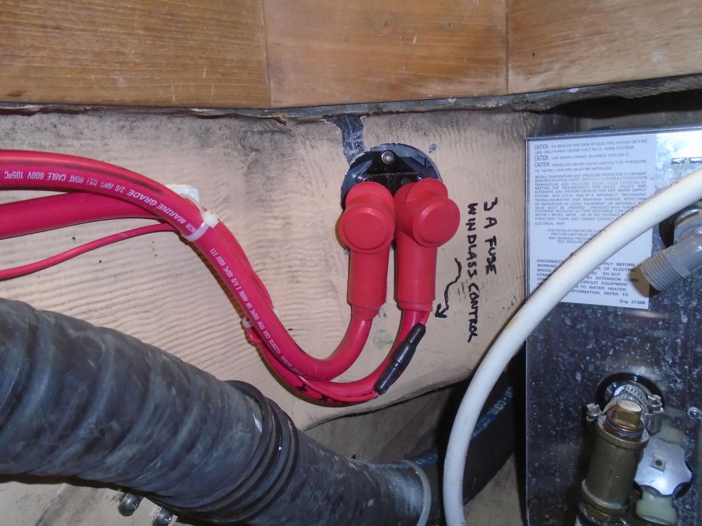
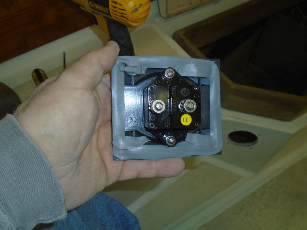
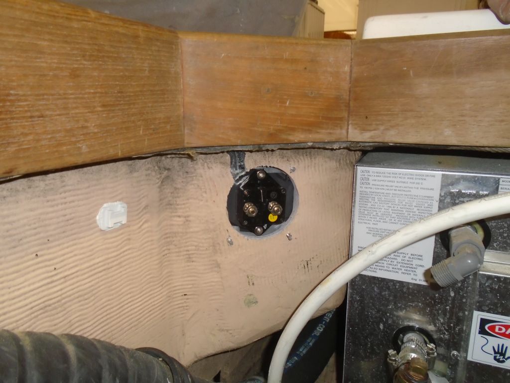
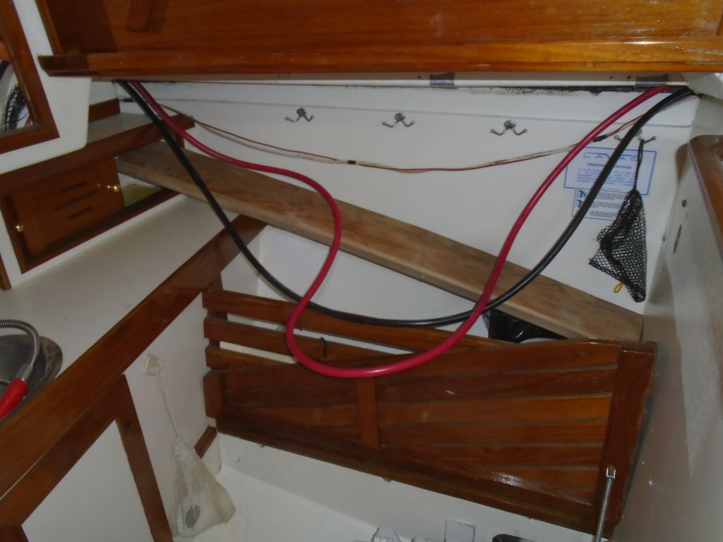
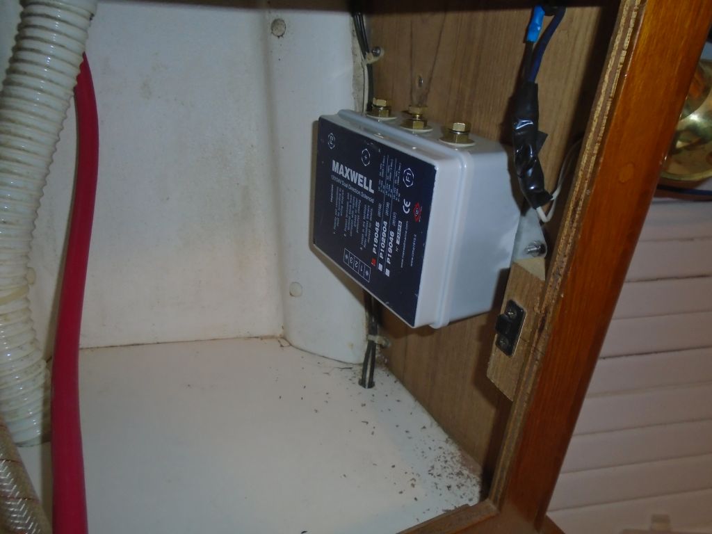
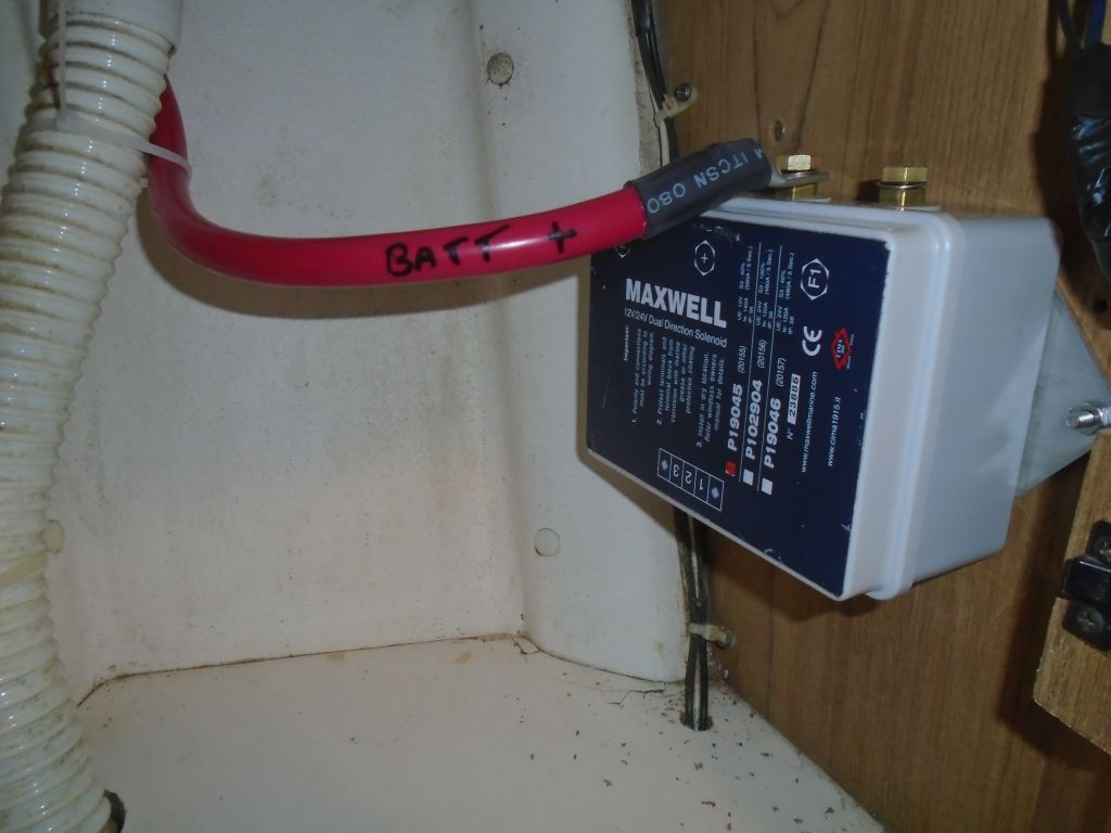
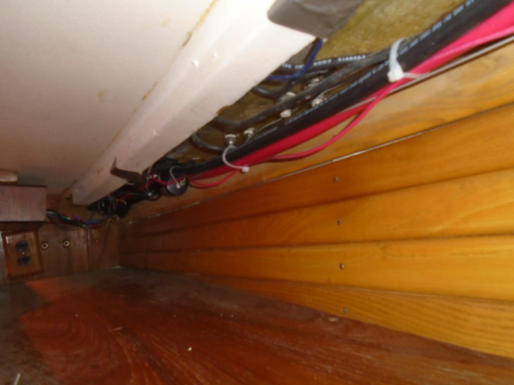
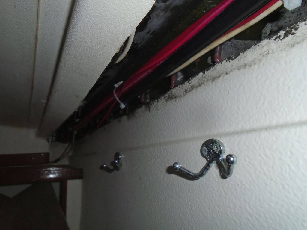
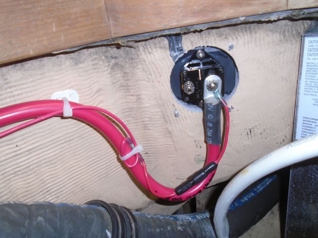
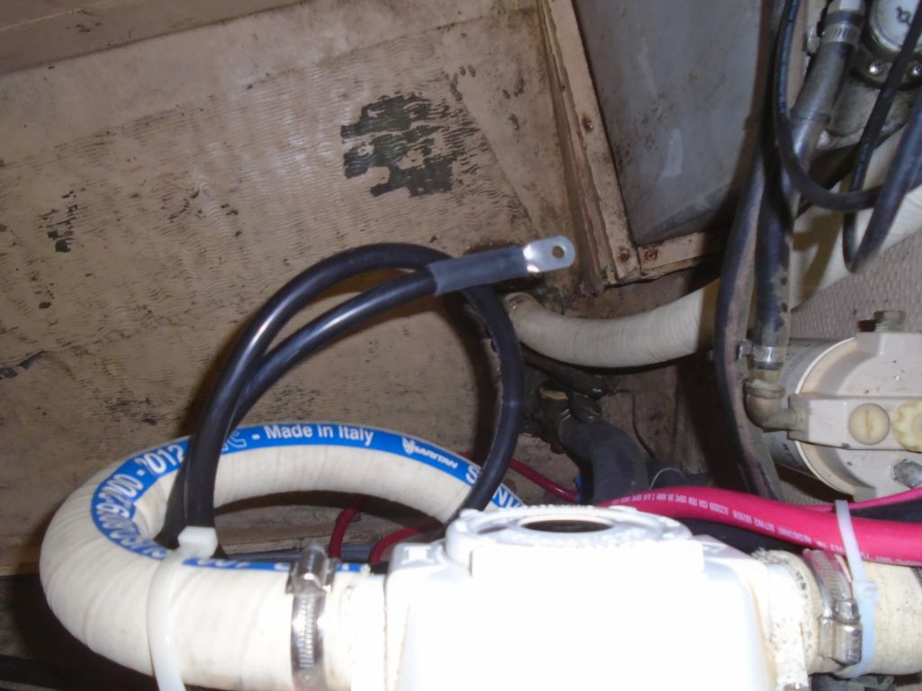
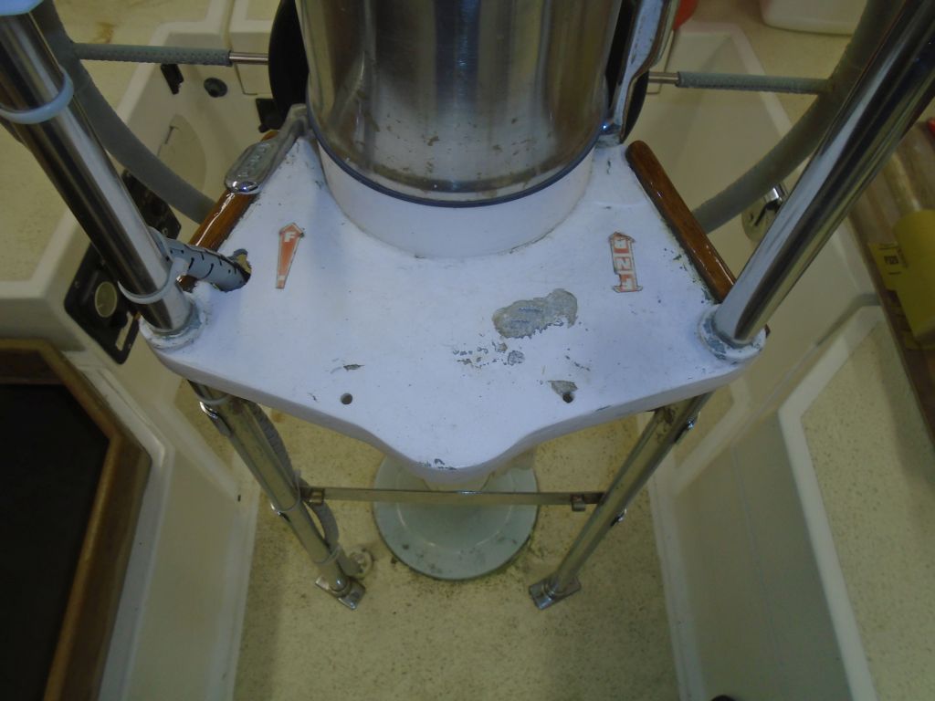
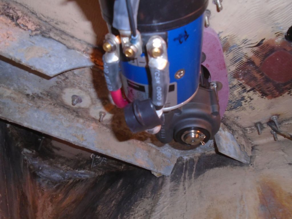
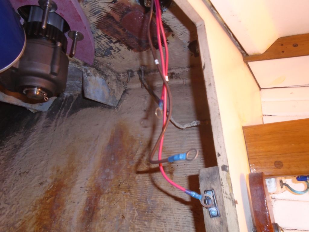
Now I could make up the final cable ends to the windlass motor.  The ground/negative cable was already terminated from earlier, and I secured it to the center post along with a smaller ground wire that led back to the control box.  Then, I cut and terminated the two positive wires (F1 and F2), which controlled the motor’s (and windlass’s) direction and attached them to their corresponding posts on the motor, and covered all three wires with protective boots and secured the cables out of the way as needed.

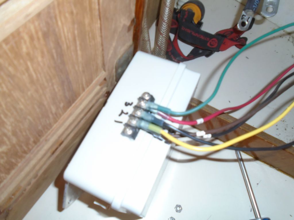
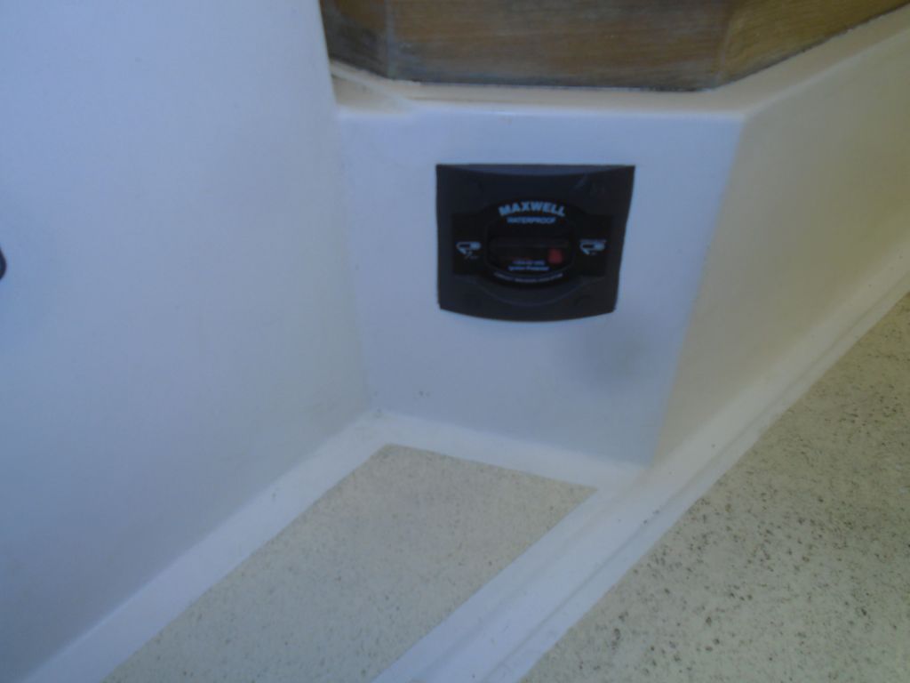
Final installation of the foot switches would await my repainting of the foredeck where I’d patched it, but while I had the wiring tools on hand I determined the lengths and made up the terminal ends of the wires to allow for easy final installation later.

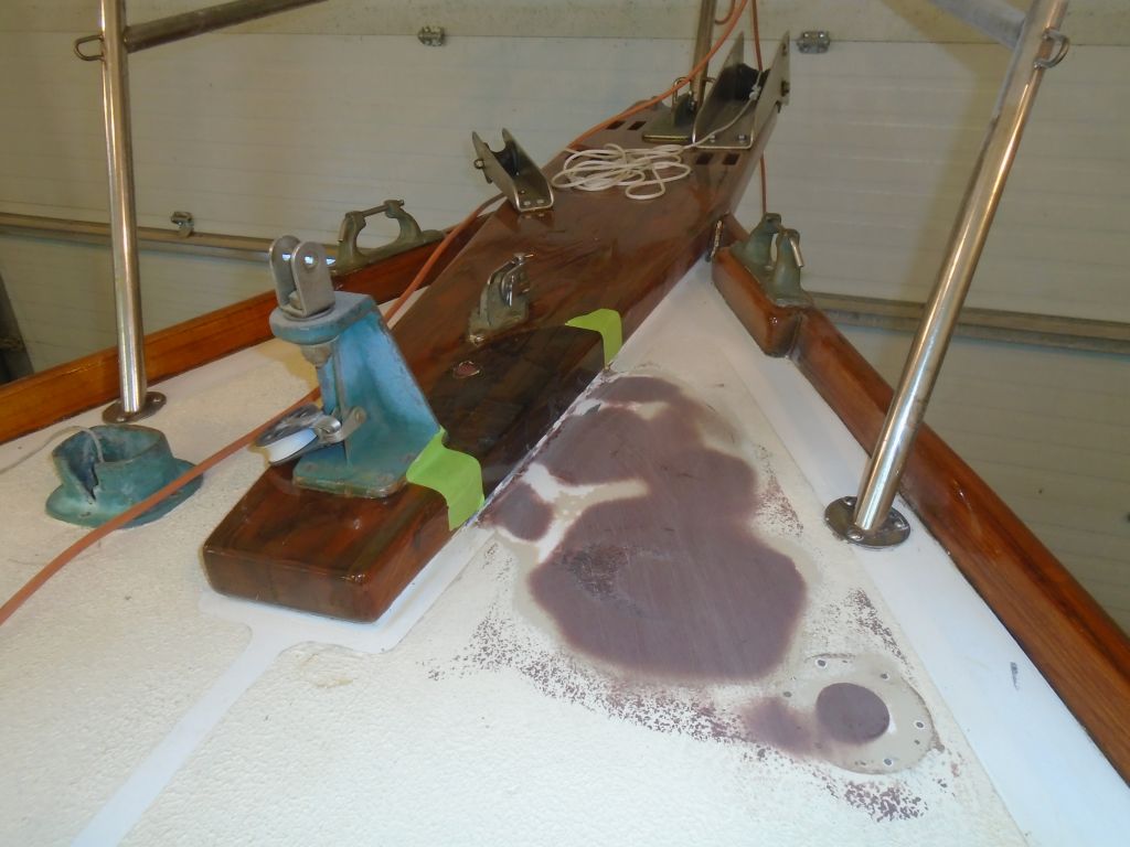
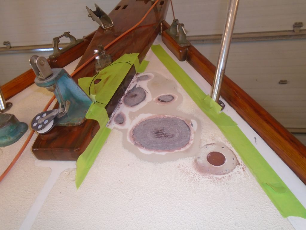
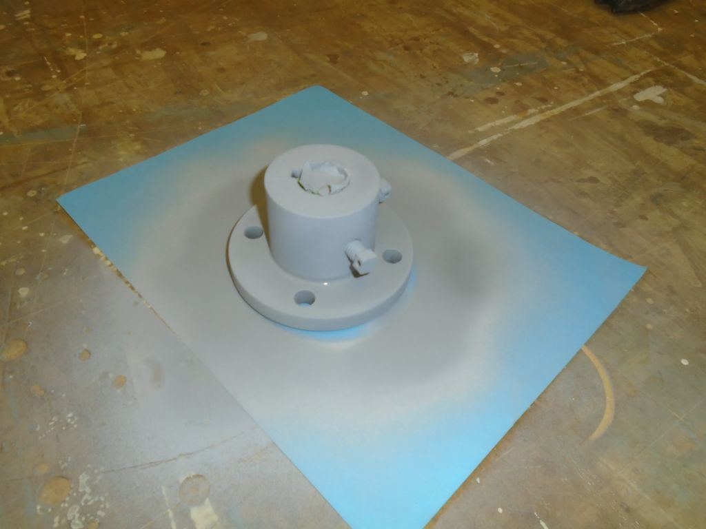
Finishing the foredeck was now a priority, so to that end I masked off as needed and prepared some epoxy primer for the newly-epoxied areas, as most one-part paints and primers wouldn’t cure properly directly over semi-cured epoxy (the alternative would be to wait a couple weeks).  I applied the primer over the epoxied areas, and this would allow me to continue with the final deck treatment as I chose.

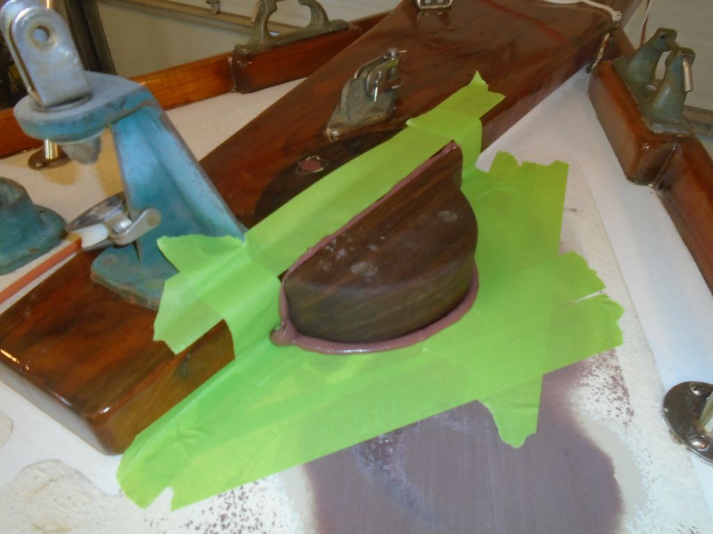
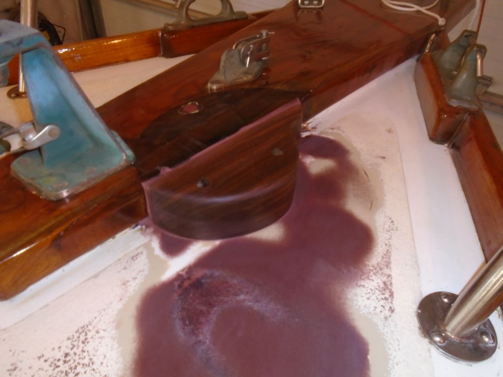
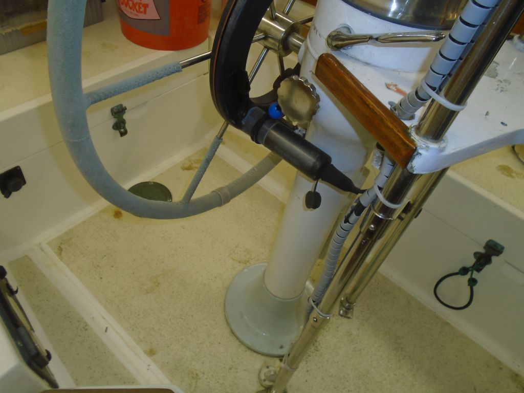
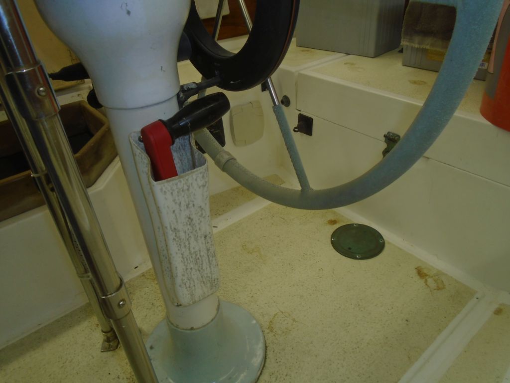
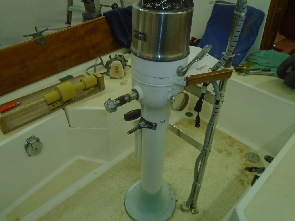
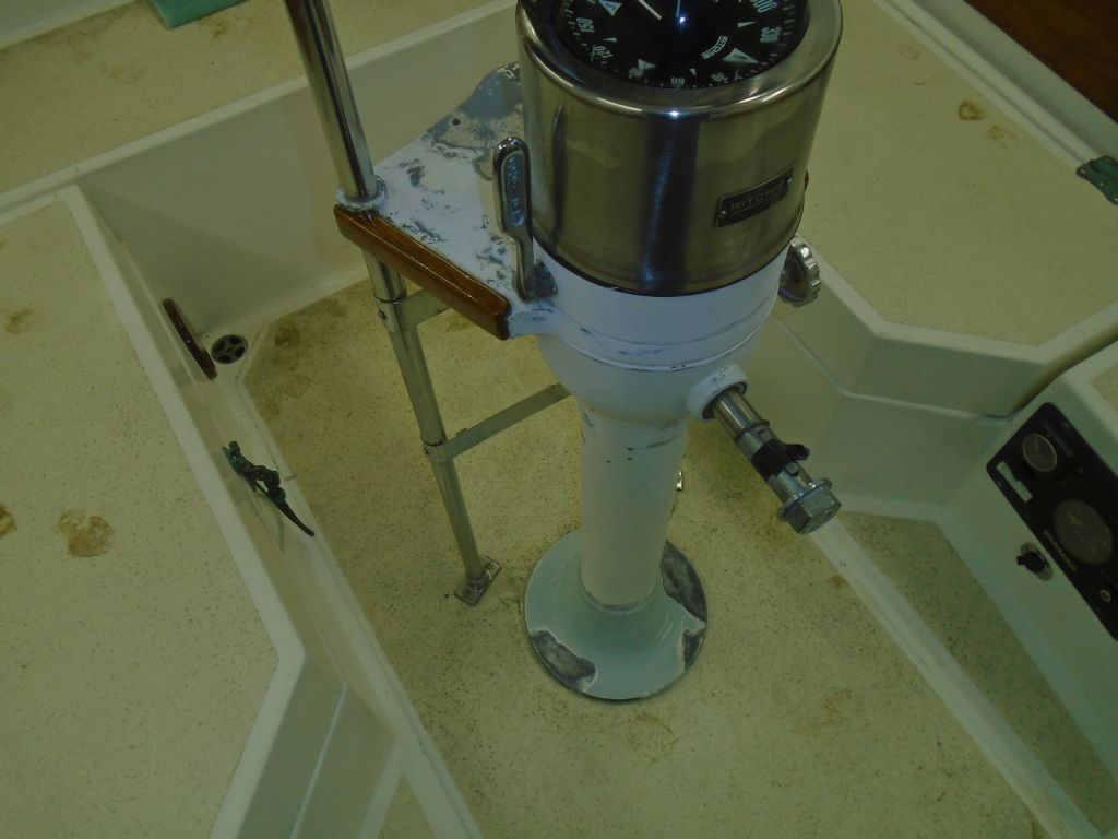
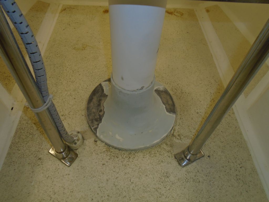
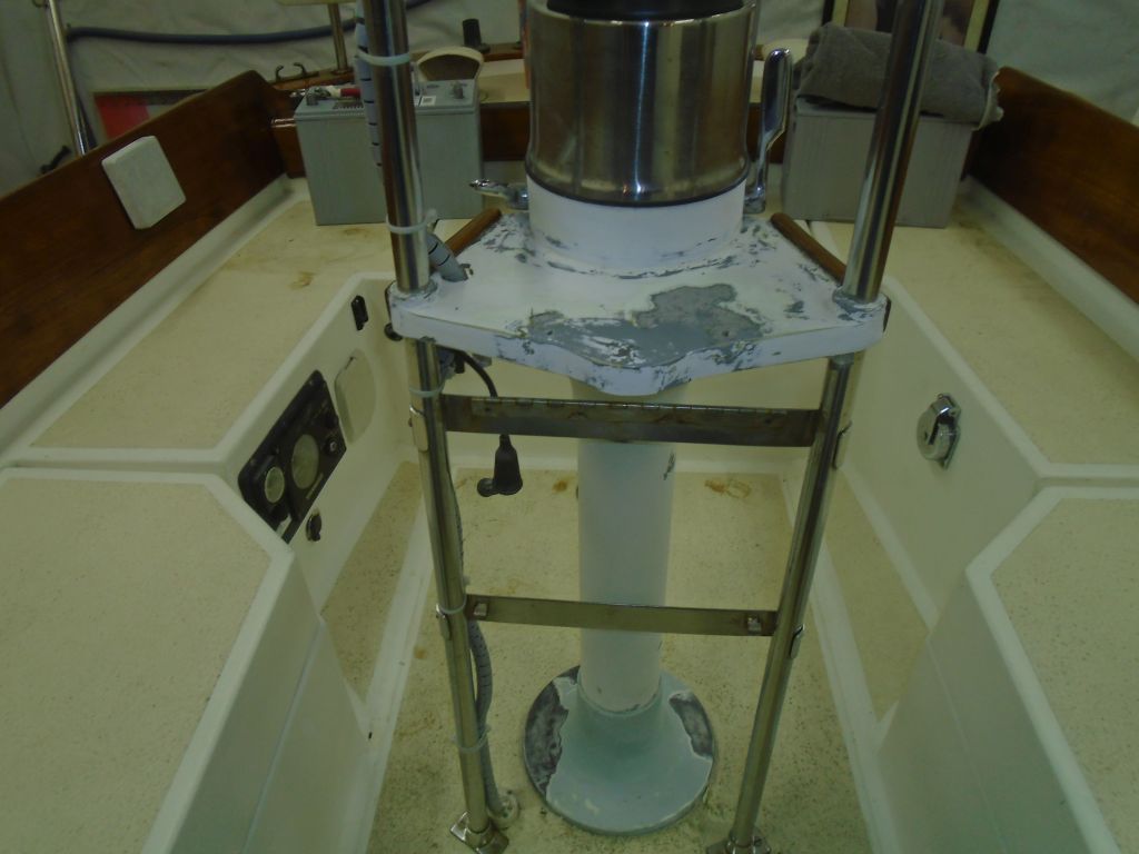
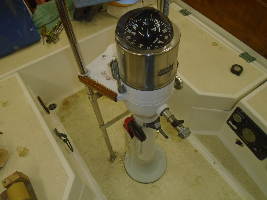
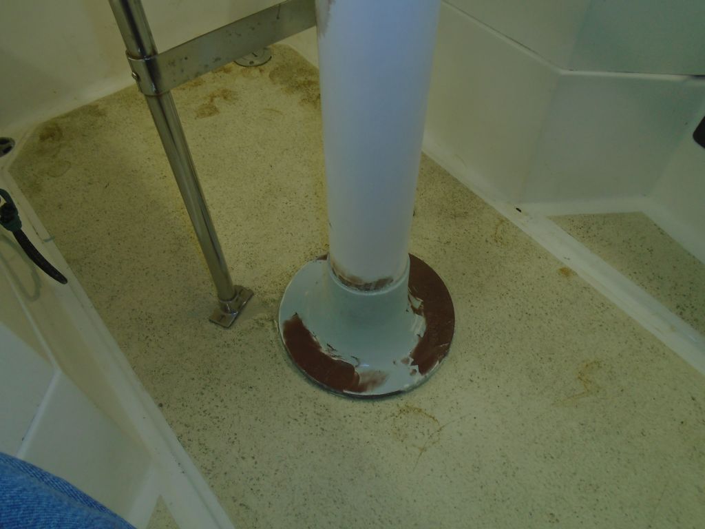
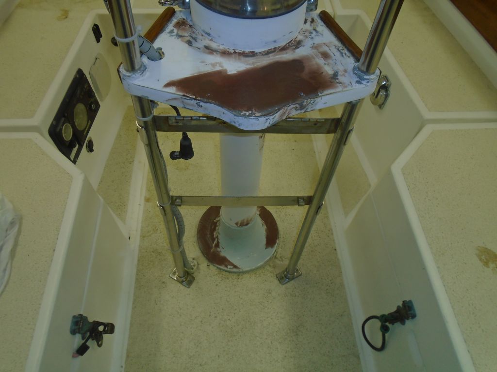
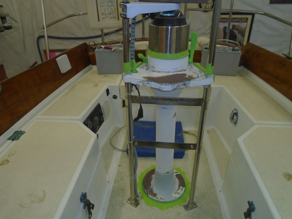
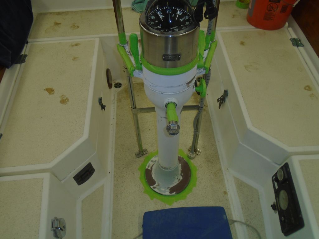
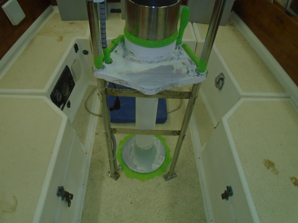
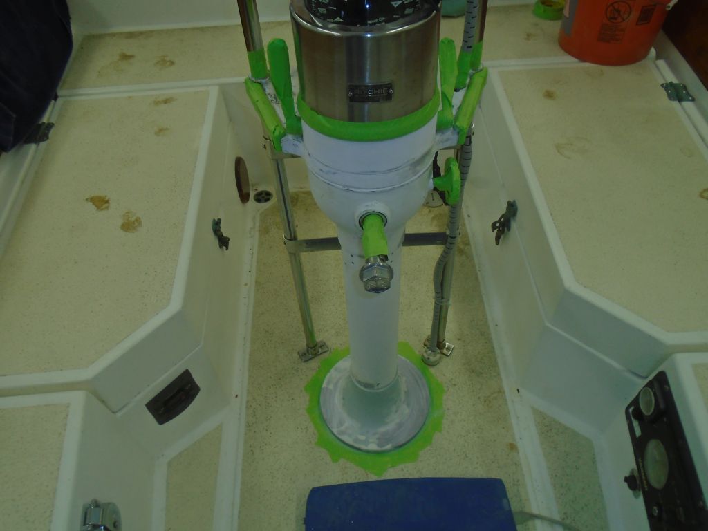
Similarly, back at the cockpit I masked off the steering pedestal as required, and applied some of the epoxy primer to the areas where I’d installed  epoxy fairing compound there as well, so I could soon continue with the final primer and paint on the pedestal.

Total time billed on this job today:  7.5 hours

0600 Weather Report:
-19°, clear.  Forecast for the day:  Sunny, high near 20, then increasing overnight to freezing and above. Snow late in the evening turning to frozen mix and eventually rain.

Danusia 35

< Back to Danusia

Friday

With a new Cutless bearing that I’d ordered after removing the shaft several days before still a no-show from my original vendor, I’d ordered another one from a second vendor, and it arrived on Thursday afternoon while I was working on a remote project.  So with plans to reassemble the shaft, stuffing box, and coupling, I got back to work early in the morning so I could finish up the stern tube repair and prepare the Cutless bearing before my helper arrived to squeeze himself back into the bilge and put things back together.

With some photos of the original setup as a general guideline for how much stern tube should be protruding from the deadwood, I mocked up the shaft through the tube now to make some reference marks and see how it all played out vis-a-vis the original photos and my own sense of things.    Eventually, I determined that the stern tube had stuck out about 2″, and I masked off a reference line at this dimension so I could cut off the excess tube.  After double-checking the dimension, I made the cut, and once more mocked up the shaft and propeller to ensure that there was ample room between the tube and the prop hub.

With the tube at the right length, I turned to the Cutless bearing.  I had to lightly sand the inside of the tube to make the fit a little easier, but then the bearing slipped in with just the right amount of friction.  The brass body of the bearing was necessarily slim, and the rubber lining minimal, in order to fit a 1″ shaft through a 1-1/4″ ID tube.

Pleased with the overall arrangement from the mockup, I prepared two threaded holes, at 9 o’clock and 3 o’clock on the stern tube and about 1/2″ in from the end, to accept set screws that would hold the bearing in place.  Before installing the set screws, I used a small drill bit to just barely dimple the brass bearing housing at each location to better accept the set screw point.  Then, I installed the bearing, using a tiny amount of sealant on the body to help secure it and leaving about 3/8″ of the bearing standing proud of the end of the stern tube.

Normally I might have liked to have faired in the tube with the aperture before proceeding with the shaft, but with a desire to wrap up the stuffing box project and with schedule constraints, I could take care of that later.  I finished up the preparations just in time for my helper Jason’s arrival, and we got right back to the reassembly, starting with cleaning up the bilge area aft of the engine while access was as good as it would ever be.

stuffingbox1-21216

The packing box hose was an extremely tight fit over the stern tube, but Jason eventually got it on and secured.  Then the space between stuffing box and transmission coupling was so minimal as to leave barely enough room to actually fit in the shaft coupling and brass key, a process made more difficult by the fact that most of the work had to occur one-handed.  But though challenging, of course it was possible to reassemble, and without too much fighting Jason got things put back together and secured the coupling set screws into their shaft dimples, and moused the bolts to prevent movement.  From there, it was a relatively simple matter to bolt the coupling back in place to the transmission coupling with new bolts.

With that done, I could start fairing the stern tube in to the aperture, much the way it had been when we started.  To save some future person some of the agonies we experienced during removal, I chose to leave the bearing set screws exposed, rather than burying them beneath the fairing as they’d originally been.  So I masked off the very end of the stern tube, and over the exposed end of the bearing and shaft, then mixed up a preliminary batch of epoxy thickened substantially with structural and adhesive fillers, smoothing it into place around the stern tube and approaching the final shape, though to avoid excess exotherm I’d do the buildup in 2 or 3 total applications.  I figured the first application would cure past the “hot” stage before the end of the day and would allow another application later, so for now I moved on to the next thing on the list.

It was time to drill the large holes required for the windlass installation, which would allow me to dry-fit the windlass and make sure everything was looking good.  So on the foredeck, I carefully set up the base template once more, ensuring its proper alignment with my teak base and, more importantly, with the anchor roller on the platform.  Satisfied, eventually, with the layout, I used a center punch to mark the centers of all the holes I had to prepare, including a 3-1/8″ hole for the chain pipe; a 4″ hole for the windlass shaft and body; and four 3/8″ holes for the fixing bolts.

Starting with the chain pipe hole, I used a hole saw to create the opening.  This was a long process, as this particular bit was very dull, as it happened.  With frequent stops to clear the teeth on the saw, and occasionally chiseling out the waste from within the hole to allow the hole saw to penetrate the growing depth, I eventually made my way through the roughly 2″ of solid teak, then a 3/8″ (more or less) thickness of solid fiberglass deck (the fiberglass was much easier to cut than the teak), then a thick layer of filler/putty/adhesive, and finally the aluminum cross member inside the chain locker.  With the nearly 4″ deep hole complete, I retired the exhausted hole saw permanently with honors.

The next hole, for the windlass shaft and body, was even larger, but as it turned out it was much easier to drill.  After giving my heavy-duty drill some time to cool off from its own heroic efforts on the first hole, I chucked in the 4″ hole saw for the final hole.  This saw was much sharper, and cut the teak with greater ease, and this large hole also ended up completely aft of the putty/aluminum structure I’d dealt with on the forward hole, so with hardly any ado at all, I was through.  Drilling the four small holes for the fixing bolts was a cinch.

The windlass fit into place quite nicely, and with it finally through the deck I could look from beneath and start to figure out the details of a backing plate that I felt was required for added strength.  Fortunately, I’d not need to worry much about building up the backing plate to match the thickness of the aluminum sub structure, as the bolting area of the windlass was aft of this point, other than one bolt that was close to the edge and would require something thicker there.


Meanwhile, on the deck side I was pleased to find that the lead from the anchor roller to the chain wildcat was even better in reality than I’d hoped for while laying out the templates.

windlass11-21216

I’d move forward with the final windlass installation details in the immediate future, but for now my next task was to seal the insides of the large holes (and, as much as I could, the smaller bolt holes) with epoxy to help protect the wood within.  Fortunately, there was no core material to deal with in any of these holes.

The windlass base itself had no flat surfaces to speak of, and wouldn’t be easy to seal well.  It came with a gasket, which hardly seemed sufficient on its own, so I’d find a way to add some better sealing material at the most critical parts of the windlass’s deck penetration.

windlass17-21216

To round out the day, I applied a second coat of filler to the stern tube, as the original coat had cured sufficiently over the past four hours.

Total time billed on this job today:  7 hours (Tim); 1.5 hours (Helper)

0600 Weather Report:
-10°, clear.  Forecast for the day:  sun, high 16°

Danusia 34

< Back to Danusia

Thursday

Early in the morning, before I had to depart the shop for a day working remotely on another project, I removed the Delrin rod from the now-cured stern tube repair.  It took only light pressure with a wrench to slightly turn and break free the rod, after which I could pull it out of the new lamination by hand.  I was very pleased with the results of the repair, and would finish up the tube extension presently.  It would require cutting to the correct length, and installation of the new Cutless bearing, after which I could proceed with reinstalling the shaft and, at my leisure, fairing the tube back into the aperture as it’d been originally.

Total time billed on this job today:  1 minute 12 seconds

0600 Weather report:
18°, partly clear.  Forecast for the day:  sun, clouds, show shower in the afternoon, high near 30 but dropping in the afternoon

Danusia 33

< Back to Danusia

Wednesday

I began the day on the foredeck, where I sanded smooth the fairing filler over the various patches.  The end result was good enough to allow me to continue with the windlass base installation.

windlassbase1-21016

After a final check and double-check of the base position and chain lead to the windlass, I masked off around the new base and prepared two fastener holes to secure it, mainly as an aid while the sealant cured as the windlass would eventually bolt right through the base in a couple places.  I drilled and tapped the deck for two machine screw fasteners, and after gooping up the deck with sealant I installed the base and cleaned up the excess.   Later, I bunged the two screw holes, even though they’d be hidden by the windlass.

I had to leave the shop for a while on an errand, but upon my return I installed new terminal boots on the windlass control box, which allowed me to tighten and permanently install the cable ends there.

boots1-21016

There was nothing more I could do on the windlass installation for the moment, and I anxiously awaited the usual UPS afternoon delivery that should contain my much-needed Delrin rod for repairing the stern tube, so with the most significant jobs in a state of suspended animation, I turned to some of the little items still on the list, beginning with perhaps the easiest of the whole project.  The owner had mentioned that the companionway slide would often slide right out in a surprising and disconcerting manner in a seaway, as there was nothing to hold it within its tracks at the aft end.  My solution to this was, as I like best, very simple.  I installed a screw on each side of the track, hidden within the track, that would prevent this movement.  There were even holes already there, suggesting that something had once been installed there, but the screw was straightforward and effective while still making it a cinch to remove the hatch slide for maintenance should it be desired.

The engine room on this boat was quite cramped, a feature of the design, and there was a number of hoses running through the space directly beneath the oil pan.  At the moment, these hoses were unsecured and rubbed on the oil pan in places, and the owner had concerns about this.    What would have been really nice would have been to reroute all these hoses (they serviced the waste tank pumpout, bilge pumps, and who knows what else, along with all the adjacent detritus required for the engine) away from the engine entirely, but as I pondered the engine room I couldn’t see any realistically feasible way to do this without basically starting over, as the engine room was tight and crammed with wiring and hoses on both sides of its narrow confines.  Over 30 years of additions, improvements, repowers, and the usual owner-effected changes tends to have this effect on things, all complicated by what was really a challenging and poorly-designed space to begin with.

Instead of wishing for what could be “if only”, I focused on the immediate issue, which was the way the hoses chafed on the engine.    The problem was really only at the forwardmost end, and to cure it for now I installed a padeye fitting on the engine bed–there was just enough room to get in there with a drill and screwdriver–and then installed several hefty wire ties to secure and pull down the hoses away from the engine.  This worked:  the hoses were free from the engine and, while they still had to run through the cramped space, at least they were no longer in danger of chafing through.  It was an imperfect solution well-matched to an imperfect world.   Anything more would have required untold hours and unforeseen issues that would be best left for some future time when a long-term maintenance outlook might dictate an overall systems replacement that would eventually be desirable to reconfigure the various rats nests that were present throughout the boat.  But for now it was all in good-enough order and working condition.

With my much-needed, non-stick 1-1/4″ Delrin rod finally on hand, I turned immediately to the stern tube reconstruction.  It was a bit of a tight fit into the original tube, so I cleaned out the innards with some sandpaper till the plastic rod fit in without undue pressure.  I inserted it far enough for stability, but not so far as to make it potentially difficult to remove after I glassed around it.  The idea of this exercise was to use this rod as a mold around which I could add on to the remnants of the original stern tube that I’d damaged–both inadvertently and advertently, as it were–during removal of the recalcitrant bearing earlier.

To ease the transition where the old tube ended, and to ensure that the inside of the completed tube was smooth and flat (well, flat in the sense of smooth), I started with some thickened epoxy putty right at the end of the old tube, which I used to even up the cut end and smooth the surface out on to the slick rod.  Then, I wrapped biaxial fiberglass around the tube in two separate pieces, which eventually gave me 4 or 6 layers’ thickness and tied the new work in with the old.  I purposely made the extension longer than it needed to be so I could cut it off squarely at the proper length later, and the uneven end of the laminate wouldn’t matter.  I think the old tube originally protruded about 2″ total from the deadwood, but I’d determine that more precisely later using the shaft as a guide, along with photos of the original setup.  I left the new fiberglass to cure overnight.

With time left in the day, I decided to lay out and prepare the holes for the two windlass foot switches.  Starting with the original switch location, where I planned to install one of the new switches, I laid out straight lines and, leaving 3″ between the switches, marked the location for the second switch.  I drilled out the main holes with a 2″ hole saw, then marked and overbored the fastener holes (all except the forward most one on each switch, which were both in an area of solid fiberglass without core) so I could omit the core from about the fasteners, as well as reaming the exposed core out from the larger opening.

Afterwards, I filled the voids with thickened epoxy and left the area to cure overnight.

Total time billed on this job  today:  6.5 hours

0600 Weather Report:
0°, mostly clear.  Forecast for the day:  clouds, chance of a snow shower, highs in the 20s


Danusia 32

< Back to Danusia

Tuesday

The best laid plans.

I discovered Monday morning that I’d actually not placed the order for various things required for rebuilding the stern tube and shafting system–everything was right there in my shopping cart, but apparently I’d never completed the order.   Stupid.  So materials I’d anticipated being delivered on that day would not be arriving after all.  Upon discovering this in the late morning, I completed the order immediately, which from this vendor would normally mean delivery by the next day–today.

But my mid-afternoon, there was no sign of UPS, and I checked the tracking only to find that for whatever reason, the order had gone out later than usual–whether a vendor delay or a shipping delay was unclear–so it wouldn’t be delivered till Wednesday afternoon now.  Sigh.  This meant I’d not be able to even begin rebuilding the stern tube till then, and with the Cutless bearing backordered I wasn’t sure the pieces would come together as I’d planned and expected, as I’d hoped to reassemble the shaft and its component parts at the end of the week when my helper was available again.  I wouldn’t be the end of the world if I had to postpone, but I disliked unfinished, pending jobs and losing momentum.

All that aside, I continued work on the windlass installation, first spending time with the sander at the foredeck to sand smooth and clean the new fiberglass patches.  Afterwards, I applied fairing compound to the area as necessary.

The piece of red 2/0 cable that remained from the main run wasn’t long enough to make up the two required pieces from the control box to the chainlocker (and windlass motor), but I had on hand some additional cable left over from another job.  However, that red cable length alone wasn’t long enough to make two pieces, though it would do one just fine.  So with the owner’s OK–asked because I hated to do this–I used a piece of black cable instead of red for the final length, as this would allow me to continue work immediately and avoid having to order and wait for more cable.  I marked the end of the cable well to indicate its color and function.

I led the two new lengths (one red, one black) from the control box into the chainlocker, leaving the excess length at the forward end till later, when the windlass was actually in place, but I made up the ends for the control box and installed them loosely on the terminals for now, as I’d need to add terminal boots later.  From my various wiring plans, I determined that I required three additional small wires (14AWG) between the control box and the chainlocker–one for ground, and the other two for the foot switches.  To make this easier and cleaner, I used some 14/3 round sheathed cable that I keep on hand for bilge pumps.  With this wire led through the wire chase and forward as needed, I could begin to secure the cables along the wire chase.

The key fob-type remote control featured a little control box that needed to be wired into the main control box, so I mounted the unit nearby.  Still, I had to extend the four wires in order to reach the main control box, and I led them out of the way across the top of the locker and down to the box itself.  I’d made the main control box easily removable since I’d anticipated that wiring access to the small terminals on the bottom would be a challenge, and now I proved the point and removed the box temporarily so I could make up the connections to  terminals 1, 2, and 3 for the remote control as well as the two foot switches.  Terminal 2 was a ground (and the other end would connect to the main ground on the windlass motor), and terminals 1 and 3 controlled windlass up and down, respectively.  I led the positive wire for the remote control to the main positive terminal on the large control box (the center top terminal).

After reinstalling the control box, I straightened out and secured the wires, completing this part of the windlass installation for the moment.  That taped-up thing near the upper right corner of the windlass box is pre-existing wiring leading to a reading lamp.

After checking over the wiring and diagrams a few more times to satisfy myself, I determined that I seemed to be done with the wiring chases in the cabin, so I reinstalled the covers and trim.

Back at the cockpit, I led the final length of cable between the “cold” (i.e. switched) side of the house battery switch, across the cockpit through a convoluted route according to where other cables and hoses were led–it was busy in there–and finally back to the windlass breaker switch near the helm.  I had just enough cable to make this run.  There was a hinged plastic cover covering the battery switch area, so I didn’t need a separate wire boot there.

I’d been planning to spend time during the late afternoon working on the stern tube rebuild, but without the materials on hand instead I turned to the teak windlass base, which I needed to get cracking on anyway, and sanded it clean and smooth, and rounded the top edge.  After a test-fit (the epoxy on the foredeck was well-tacked by now), I laid out two screw holes that I’d use to help secure the base during installation, and applied a sealer coat of varnish to the new teak.

Finally, I started varnish work on the top side of the cockpit table, coat #2 here.

varnish1-20916

Total time billed on this job today:  6.5 hours

0600 Weather Report:
12°, light snow, about 6″ overnight.  Forecast for the day:  snow ending, cloudy, high around 25

Danusia 31

< Back to Danusia

Monday

Having ignored the steering pedestal at the end of last week, I took several minutes first thing to clean and sand the last application of fairing filler on the base.  The pedestal was now ready for primer, but for the moment I had bigger fish to fry, so I’d get back to the pedestal in due course.

pedestal1-20816

I set up for and spent some time sanding the foredeck, both above and belowdecks,  to prepare the various obsolete holes in the deck for filling and patching so I could continue the physical windlass installation.  This included the old windlass shaft hole and bolt holes, the old manual chain pipe, and the old foot switch opening.  After cleaning up, I masked off the holes from beneath.

I trimmed the teak windlass pad a little smaller, which I thought looked much better, and spent a few moments working on its basic placement once more, as yet another confirmation of the location and to ensure that the way was clear in all ways, above and belowdecks.  The chain pipe was close to the staysail stay location, but with the large full-width glassed-in aluminum backing plate beneath I didn’t think there would be an issue with support.  This area of the aluminum (as seen in one of the photos above) was already partially cut away and corroded from the old windlass installation, and happily the new chain pipe would pass right through this area.

Next, I filled the  various holes with a thickened epoxy mixture.  Later in the day, when the fill had cured somewhat, I applied fiberglass patches to the top sides of the openings where needed.   I didn’t fiberglass the switch location since I planned to locate one of the new switches in the same place, but since it required a different sized (and much larger) hole I’d filled the original so I could redrill as needed.

Preparing for the new windlass wiring, I installed wire tie mounts along the underside of the deck in the port wiring channel.

windlass1-20816

The windlass required a main breaker, and we chose to locate this in the cockpit.  I found a good spot near the helm on the port side, which was convenient to both the main power source (battery) and the route forward for the wires.  I installed the breaker in the huge hole required for it.  (What is it with equipment manufacturers’ obsessions with massive holes for their installations?)

Now I led in new cables for the windlass, size 2/0.  This is what had been in place for the old windlass, but I realized belatedly that they were somewhat larger than what was actually required by the new unit.  Better to have too much cable size than not enough, but the heavy cable was no fun to work with.  I spent some time interpreting the various wiring diagrams for the windlass and its accessories, working up my own rough drawing for the wires required for this specific installation, including two foot switches and a remote control unit.

windlass12-20816

Space considerations and manufacturer admonishments dictated that the windlass control box (aka solenoid) be mounted safely away from the chainlocker, and there happened to be a relatively convenient space in a locker at the aft end of the port v-berth.  The control box was very large but easy to mount with a pair of bolts, retaining decent if not ideal access to the cable terminals on top and smaller wiring terminals on the bottom.

windlass15-20816

There’d be a pair of the heavy cables running from the control box to the windlass itself, and one positive cable from the cockpit (breaker switch/battery) to the control box.  In addition, one negative cable had to run from the battery compartment directly to the windlass motor for grounding.  So with the two longest runs led in, I made up the first two terminal ends as needed, for the control box and (eventually) the negative cable for the windlass motor.  I also led in a smaller wire required by the wiring diagram.  These were all the longest wires in the installation.

This allowed me to pull back and tie up the excess wire along the wiring route aft and into the cockpit locker so I could make up the ends there as needed.  The exact termination point of the negative cable would probably be a battery terminal, as I didn’t see a negative distribution buss, but with the batteries removed and not a lot of excess cable I simply made up the terminal at the very end of the 35′ of cable length that I’d provided, which would allow it to reach to the battery compartment easily.  For the positive wire, I ran it aft to the new breaker switch, where I installed it (and the smaller wire mentioned above) to the proper terminal, along with a terminal cover.  I’d continue the wiring next time.

Total time billed on this job today:  7.75 hours

0600 Weather Report:
10°, mostly clear.  Forecast for the day:  clouds increasing, breezy, snow late in the afternoon and evening.

Danusia 30

< Back to Danusia

Saturday

Sometimes I liked to take  a few moments during the weekend to catch up on or redact various small jobs from my list, and with some time on hand during the afternoon I decided to finish up the varnish work (hopefully) on the companionway swashboards and reverse side of the cockpit table.

varnish1-20616

Meanwhile I sprayed a few coats of paint onto the coupling.  I like bright and frankly fun colors for couplings.

coupling1-20616

But this incidental stuff–necessary as it was–wasn’t the main focus.  The owner had requested that I replace the gaskets on the two deck hatches, as well as install a second set of hatch dogs on the midships hatch, which he said didn’t seal all that well.  So to this end, and with new materials on hand from the hatch manufacturer, I removed the two hatches from the boat to the bench to make the job easier.

Starting with the midships hatch, I first contemplated the extra hatch dogs and whether I could–or wanted to–attempt their installation.  In due course and after studying the new parts and existing dogs, I decided the job was feasible.  The dogs required a hole through the cast aluminum ears on the hatch–these were not predrilled at time of manufacture–and then installation was theoretically simple with a friction pin and small spring.

Drilling the holes wasn’t difficult other than the fact that the shape of the drill, and minimal clearance at the hatch, prohibited me from drilling the second part of the hole (through the second of two ears at each location) with the power drill:  the bit would have ended up at a wacky and unacceptable angle.  A right-angle drill I had didn’t help the issue any, but then I recalled a little hand-powered drill I’d always kept in an on-board tool kit in the past, and this proved to be a good tool to complete the holes through both sides.  If the material hadn’t been aluminum I’d never have tried it (nor, frankly, would I have tried any of this installation).

hatchgaskets5-20616

With the holes drilled, installation of the new dogs was easy.

Next, I removed the old gasket, which was quite similar to that which I’d recently installed in the bronze ports.   The replacement gasket sold by the hatch company featured a self-stick adhesive line (covered with orange protective material), and I had serious doubts as to the staying power of this adhesive, so at the onset I was prepared to use my gasket adhesive to install the new gaskets as well.  But as I removed the old gaskets, I saw the same sort of self-stick adhesive, and I had to say it was surprisingly tenacious, and this allowed me to hope that perhaps the new would work well, which would make installation a snap.

And so it was indeed.  With a scraper in the form of an old 1/4″ chisel (I tried heat, but it made the removal harder, not easier), I removed the old gasket, and cleaned up any remnants left behind before solvent-washing the gasket cove.  Then, I pressed the new gasket into place, removing the protective strip as I went to expose the adhesive strip, and taking special care in the corners.  It worked–and worked apparently quite well, though I supposed only time would tell.  I put the seam right behind one of the hatch dogs, and glued the cut ends together with some of the gasket adhesive.

Frankly surprised and happy with the installation, I repeated the process with the forward hatch.  This hatch already had four dogs on it, so I simply replaced the gasket.

This was a nice little project to expunge from the list, and with any luck I’d be regarded as a hero come the first thunderstorm or heavy seas encountered.

Total time billed on this job today:  2 hours

0600 Weather Report:  15°, clear.  Forecast for the day:  sunny, 30s.  Nice.

Danusia 29

< Back to Danusia

Friday

I’d lined up a helper to remove the shaft coupling and stuffing box, as I knew he’d fit in the space more easily than I.  The shaft had to be removed in order to replace the stuffing box hose, and the owner had been unable to remove all the packing from the nut while it was in place (space was very limited and prevented access into the nut).  Before Jason’s arrival, I worked to prepare tools I thought we’d need for the job, and once he was here I played gopher for a while, but tried to do some other jobs while I was not immediately needed for his assistance.

With Jason crammed into the locker beneath the cockpit, we got to work.   The basic procedure was to unbolt the shaft coupling from the transmission, which went fairly well with no real issues other than trying about six different wrench sizes on the coupling bolts before he found the right one:  they were oversized heads and turned out, finally, to be 17mm.

Once the coupling was free, with considerable effort (a harbinger of things to come) we pulled the shaft back enough in order to fit a spacer between the shaft and the transmission coupling.  For this purpose I’d sourced a variety of 7/8″ diameter pipe nipples of various lengths.  With a 1″ shaft, these would stay within the shaft footprint and allow us to pull the coupling off the shaft with long bolts threaded into the transmission coupling.  A simple task in theory, but one greatly complicated by the challenging access and the minimal space available between the transmission and the stuffing box, which limited how far back the shaft could be pushed and spaced.

Over the next few hours, resetting the equipment several times (a few times because the threads on the bolts, as the coupling moved forward, contacted the transmission and had to be spaced further back, once to replace the spacer with a longer one), Jason eventually released the coupling–a long, tedious process, a snippet of which is shown below for all to enjoy.

During this time, the shaft often became very difficult to turn at all, and seemed to be binding in the Cutless bearing.   As the coupling moved forward, slowly, off the shaft, the exposed key in the shaft started to get close to the stuffing box nut, and with such tight clearances we eventually decided to cut off the old stuffing box hose to increase the room as much as possible.  Fortunately, Jason found that the old clamps came off  easily, and the old hose was easy to cut lengthwise and remove.  Replacing this hose, and repacking the stuffing box, were the whole point of this operation in the first place, of course.

With the coupling finally off, it should have been quick and easy to pull the shaft.  In fact, I’d hoped to do this, repack the stuffing box, and reinstall everything on this day.  Alas, this was not to be.  The earlier issues we’d encountered with the tightness of the shaft now prevented the shaft from moving basically at all.   We couldn’t turn it, and couldn’t pull it.  At the deadwood, I could see the problem:  the Cutless bearing was coming apart, and the rubber inside was clearly binding the shaft.

I’d neither wanted nor expected to worry about the Cutless bearing, but since the shaft was immobile there was no choice but to get it out.  The bearing was housed in a molded (so I thought at the time) protrusion in the aperture, and I was initially unclear how best to proceed.   Eventually, I cut away some of the material surrounding the bearing–it turned out to be only polyester filling material so the removal was easy with a grinder.  This process exposed the end of the actual stern tube, with the bearing inside and secured with a pair of set screws, which were interestingly–and unusually–seized together with wire.

Now that I could see the situation, I proceeded a little more slowly, and cut and chiseled away enough additional material to fully expose the set screws, and cut away a bit extra of the fiberglass stern tube to expose the end of the bearing.  This would allow me to get a wrench on the bearing and hopefully pull or twist it out.  (Teaching Moment:  always leave some of the bearing exposed at the end of the stern tube to allow for this without dramatic surgery!)    With Jason still on hand to help, I put a large set of slip-joint pliers on the newly-exposed section of the bearing, and twisted, while Jason pulled.  After some exertion the bearing (with shaft firmly stuck within) spun, and we had won.  From there, the shaft came out easily.

Annoyed and frustrated with this turn of events, I didn’t take pictures throughout the process, but these photos show the aperture shortly after shaft removal, showing the area where I ground and cut away material.  This process also shortened the fiberglass stern tube a bit, but all that would be straightforward to rebuild now that the shaft was out.

With the shaft out, Jason could clamber once more into the bilge to remove the remains of the stuffing box (we hadn’t been able to pull the shaft far enough back before to remove the stuffing box from the inside), and cleaned up the now-empty space, bringing his help to a close for now.  Obviously reinstallation of the new parts would wait till another day.

Afterwards, I got right into the rebuilding of the stern tube and aperture.  I started by sanding away the bottom paint and barrier coat all around the area to be rebuilt, and this eventually led me to notice small cracks at the seam where the old gray polyester filler ended, so with a chisel I knocked away the remains completely–better to start anew anyway, and it took only a pair of seconds (polyester= poor secondary bonding, i.e. adhesive ability= easy to knock away in a pair of seconds).  Then I cleaned up the whole area to prepare for the new work.

The stern tube was 1-1/4″ inside diameter, which dictated the size of the new bearing, and I immediately ordered a replacement bearing so that would be on hand soon.  Meanwhile, hoping to rebuild the now-truncated stern tube immediately,  I searched through materials on hand looking for a larger piece of tubing to slip over the existing length of tube (1-1/2″ OD), or something to insert within to act as a mold for new fiberglass.  I didn’t have anything on hand of the right size, so I ordered some slippery plastic rod that I’d use, upon arrival, to mold a tube extension as needed.

I moved on, and spent the rest of the afternoon cleaning up the existing parts and preparing everything for reinstallation.  I began with the shaft and old bearing, which were firmly conjoined.  With the piece held in a vice, I carefully cut through the shell of the bearing, which eventually–but still with surprising effort–allowed me to remove the offending thing.  The rubber was trashed, and clearly it was just as well that this all happened now, so the whole shafting system would be good as new once reinstalled.

The shaft was in good condition despite it all, with just the most minor of scoring (virtually inevitable) visible at the location of the old, burned-out and rock-hard, flax packing, three old rings of which were still in the packing nut and were the root cause of this whole exercise.  I cleaned up and polished the old shaft and its two brass keys.

The steel coupling was in good shape, and with a little work I cleaned it up to remove rust and make it easy to slip on the shaft, which was important since reassembling all this in the boat later would be a trial in itself given the limited space available.  I ordered replacement bolts for reinstallation.  Once I was satisfied with how it fit on the shaft, and had cleaned up the exterior sufficiently, I sprayed some primer on the coupling to prepare it for paint that would limit further corrosion in years to come.

I cleaned up the bronze packing box as needed, and applied grease to the threads, which would keep it working well for many years.  Now I cut new packing rings from graphite-impregnated packing, which was slippery and greasy where old flax was dry and hot.  I tried for four rings within the nut, but this filled it too far to thread on, even after I tightened the nut (with three rings inside) onto the packing box body to attempt to compress it.  Graphite packing doesn’t compress the same way as flax either, likely a good thing over time.  In the event, and satisfied with three rings, I set the packing by installing the packing box over the shaft in a  mock installation, which formed the packing nicely to the shaft and prepared it all for reinstallation.

To allow more room for assembly and later packing box maintenance, before Jason had left we’d determined that the packing box hose could be a bit shorter than original.  The old hose was already longer by a bit than the replacement, but to maximize room for the coupling and packing nut I trimmed about another 1/2″ from the new hose (taping off a nice straight cutting guideline first), which left plenty of hose for four clamps but didn’t waste any space.  Frankly, the use of cheap clamps with non-stainless adjustment screws on the original hose had directly led to the potential failure of the whole thing–and this project.  The hose itself was suspect only because the clamps had cut into it badly, and the rust from the clamps never did anything nearby any good.    Better original materials might have saved a couple man-days of labor.  The new hose and all-316 clamps cost a grand total of about $20, by comparison.

This all certainly took most of the day, but at the onset, before things got more complicated, I managed to steal several minutes here and there to work on the teak platform extension for the windlass.  A little fine-tuning of the contour allowed the top to be flush with the adjacent platform, and with this complete I could lay out and cut out the shape according to the windlass base itself.  I initially cut the platform 1″ larger than the actual base, but upon reflection I thought this was a little large, and I planned to trim the excess by 1/2″ for better appearance.  But I didn’t get that far on the job on this day.

Total time billed on this job today:  7 (Tim) 4 (helper)

0600 Weather Report:
35°, cloudy, snow just beginning.  Forecast for the day:  Snow, 3-6″ predicted.  8-10″ received.  Ground very soft from several warm days.

Danusia 28

< Back to Danusia

Thursday

Errands for another project and unrelated chores took up most of the day, but back at the shop I got to work again on the pedestal, sanding and preparing the new epoxy-faired areas and applying additional material to those areas required (just the base).

The new port gaskets appeared to set up well and were well-adhered after being pressed overnight.

portgasket1-20416

One of the first steps required before installing the new windlass was to prepare a new deck plate to equal the height of the adjacent bow platform and support the windlass.  To begin, I finalized my installation template, testing it against the gasket included with the windlass to ensure it was the right one (the manual and online offered several templates that looked similar, but were different).   Then, I cut out the paper template, which I’d use during the next phases of installation prep.

With the new template and a couple pieces of scrap teak, I repaired to the foredeck to mock up the new windlass base.  The two pieces I had were oddly-shaped, but together made the thickness almost perfect–just a little high, which was ideal.  Satisfied, I epoxied the two pieces together to make one, thicker piece from which I’d later cut out the new windlass base as required.

Another early consideration was the eventual placement of two foot switches.  Space for these was limited by several factors, first and foremost being the location of the chainlocker bulkhead (represented by the forward edge of the green tape in these photos).  The switches needed to be located forward of this line to allow for wiring.  The existing bronze chain pipe was also a complicating factor at the moment, as it severely limited where the new switches could go.  I mocked up three different versions of the switch placement, the third of which approximated how the switches might be located if the chain pipe were removed.  Though we’d earlier discussed leaving the chain pipe in place, it was no longer needed (and there was another on the port side, and I leaned towards removing it to allow for the fewest impediments to the switch placement.  In small boats the options are rarely ideal (nor, come to that, are the windlasses that carry the name), but one must work with what is available.

Total time billed on this job today:  3 hours

0600 Weather Report:
45°, cloudy.  Forecast for the day:  foolishly warm, 50, possible showers then sun

Danusia 27

< Back to Danusia

Wednesday

Back in the varnish room, after the usual round of sanding I applied the fifth coat of varnish to the swashboards and cockpit table (bottom side).  Meanwhile, with sufficient base coats on the cabin sole hatches, I switched to the rubbed-effect interior satin varnish for this coat.

The steering pedestal wash showing some age, and had been touched up a few times in the past.  The original coating, where in good condition, was well adhered and immobile, but there were the usual flakes of bubbly corrosion here and there, calling for a spruce-up.

I removed the wheel and winch handle pocket for better access, and spent some time scraping and sanding as required to prepare the pedestal for new coatings.  Attempting to remove all paint would have been an exhausting fool’s errand, so where the existing coating was in good shape I lightly sanded as needed, and focused on those areas where the old coatings were failed, feathering the areas together as much as possible.

After cleaning up and a solvent-wash, I applied some epoxy fairing compound as needed to clean up the transitions between the bare spots and surrounding areas, particularly on the pedestal base where previously some sort of heavier material had been applied at some point (it was a different color and clearly not an original treatment).  There’d likely be call for another round of this minor filling before the pedestal was ready for new paint.

Next, I turned to the port gaskets, which required replacement.  The old gaskets appeared original, and were actually in fair condition, appearance-wise, still with some flexibility, but clearly they’d been around the bend a few times.

With new gaskets from Spartan Marine on hand, which were pre-assembled into the proper lengths to fit the oval ports, I got started by removing the old gaskets, which were glued in place.  I found that a small, old utility chisel worked well to remove the old gaskets.  At first, I found that the gaskets came out in many pieces, but as I honed my technique over subsequent ports the process became a little smoother, depending on how much glue had been used originally.  I got one of the eight out in a single piece, shown below next to one of the new gaskets.

After I’d removed the gaskets and scraped out as much of the old bits remaining as possible, I lightly sanded the cast cove (which contained the round gasket material) to clean it, then washed with acetone.

I installed the new gaskets with gasket adhesive, which seemed little different from ordinary contact cement.  According to product directions, I applied the adhesive to both surfaces–gasket and port body–and pressed the gaskets into place, where they stuck into the cast grooves.  Then, I closed the ports and dogged them down tightly to press the gaskets into place and, hopefully, set them permanently.

Total time billed on this job today:  6.5 hours

0600 Weather Report:
25°, cloudy.  Forecast for the day:  mixed precipitation changing to all rain and warmer, 46°

Older posts Newer posts