Tuesday
I had only a couple short hours for shop work in the morning, as I had to depart for an appointment and also to pick up the pallet of plastic “lumber” that I’d ordered for the deck trim according to the owner’s wishes, and which had arrived at a local shipping depot a few days earlier. This errand and other, unrelated stops kept me out of the shop for the bulk of the day.
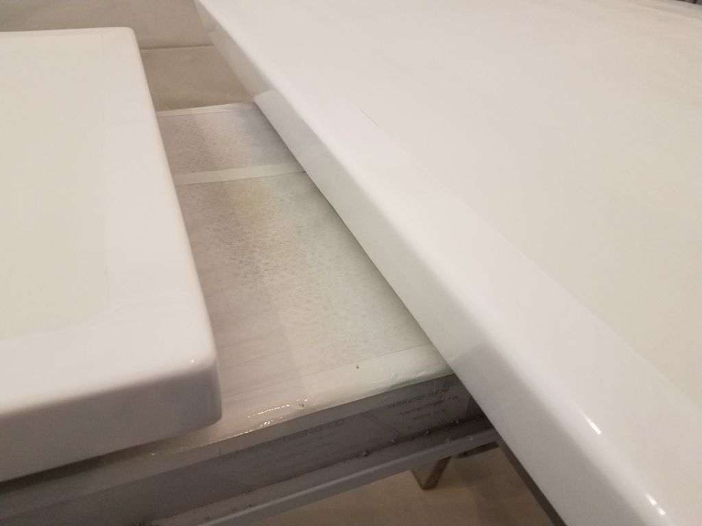
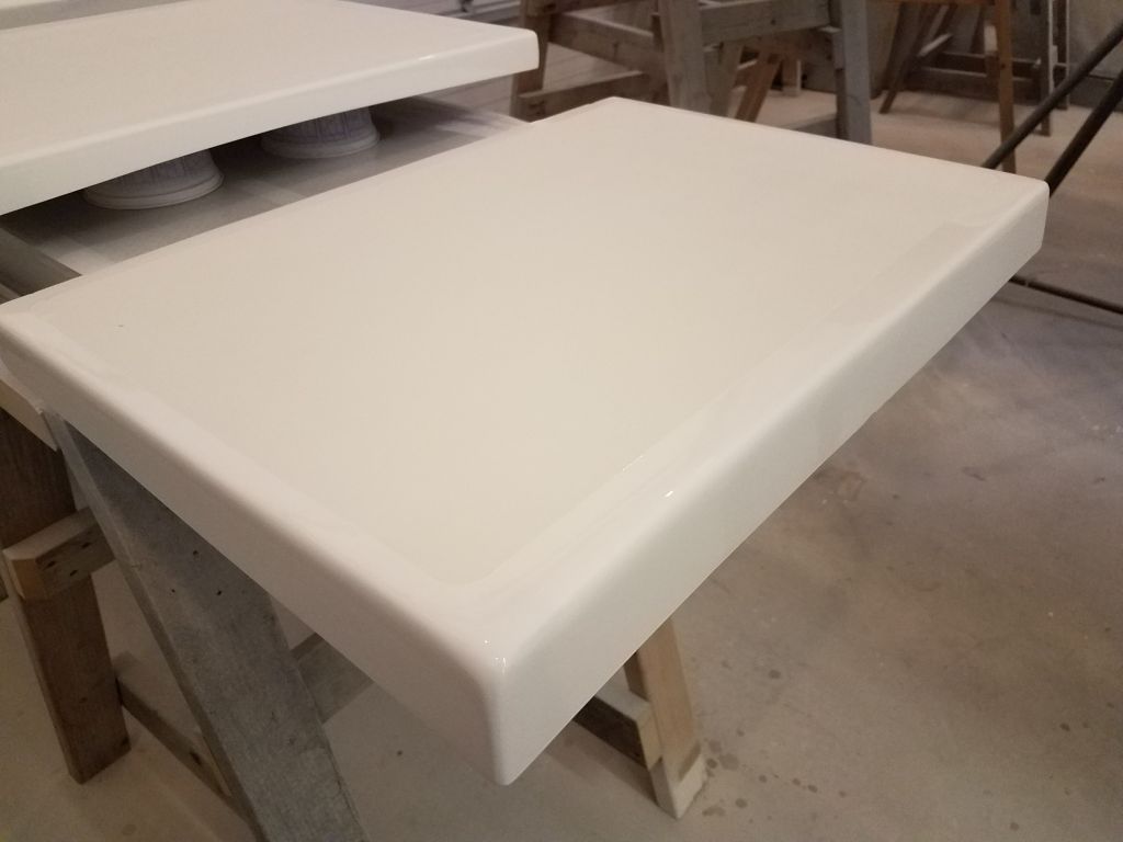
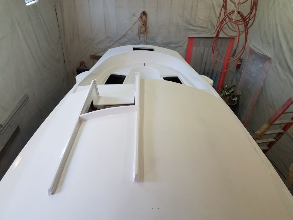
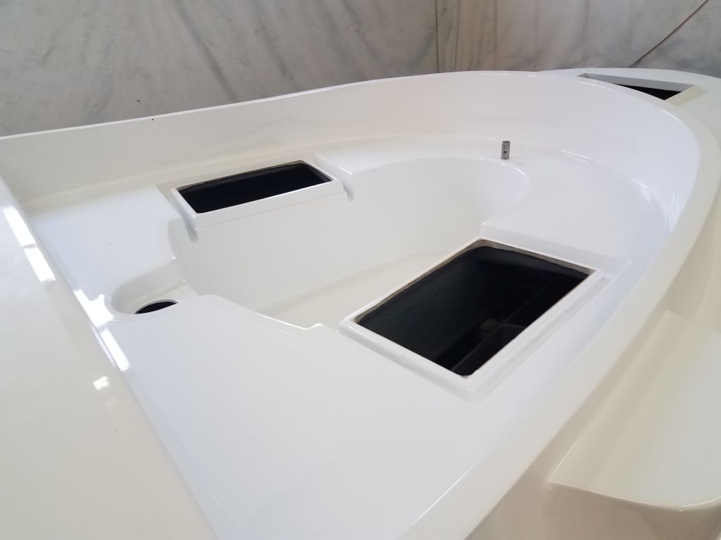
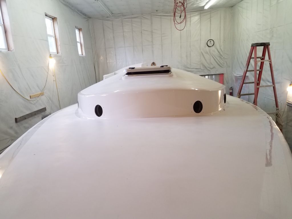
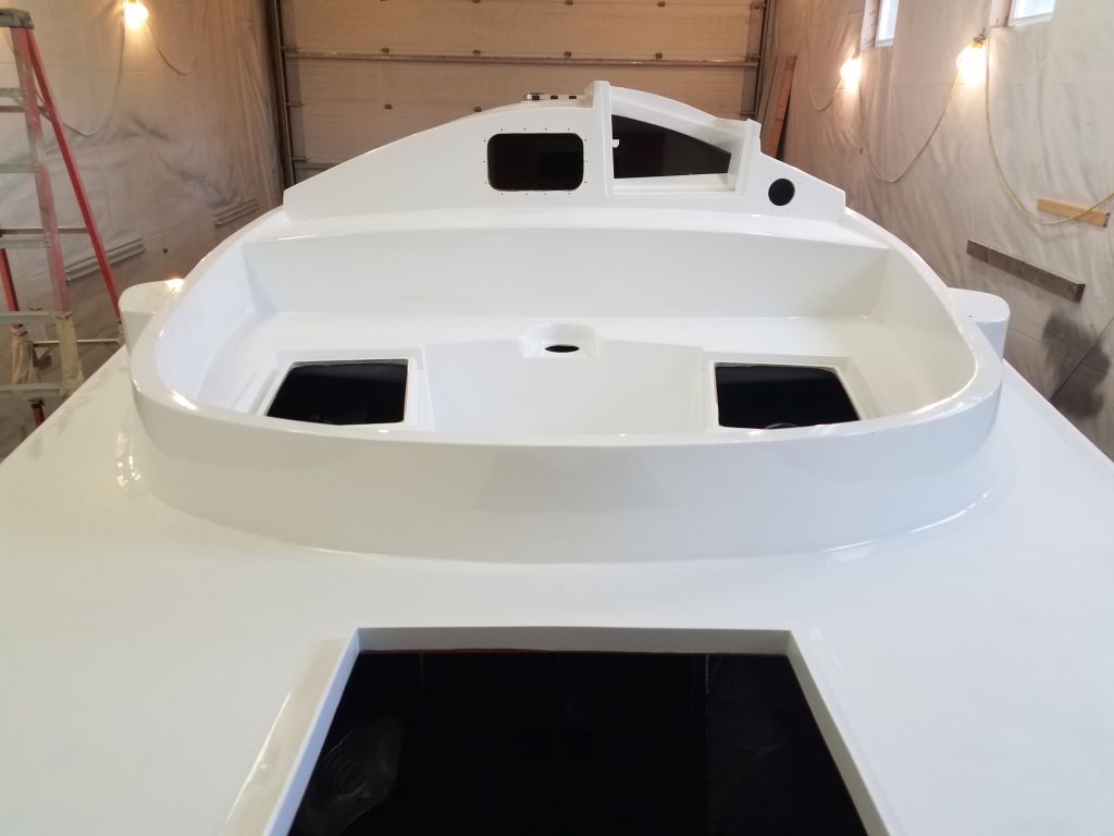
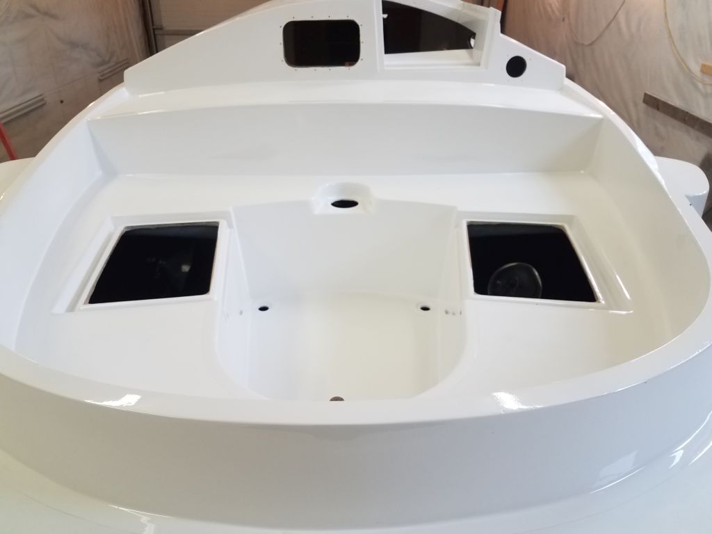
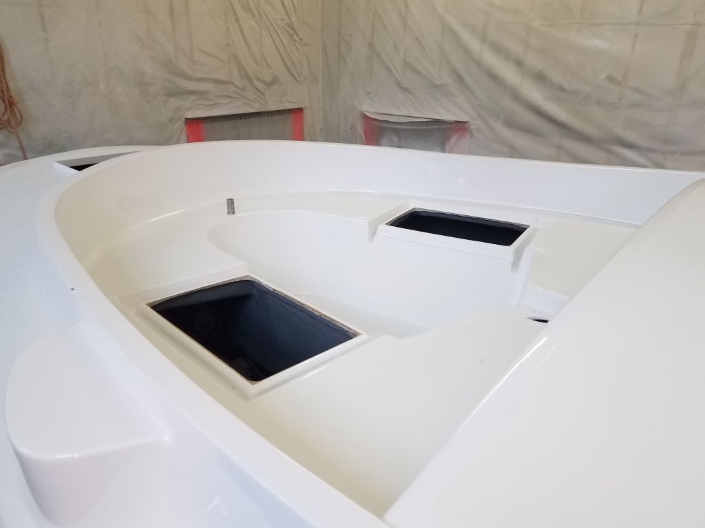
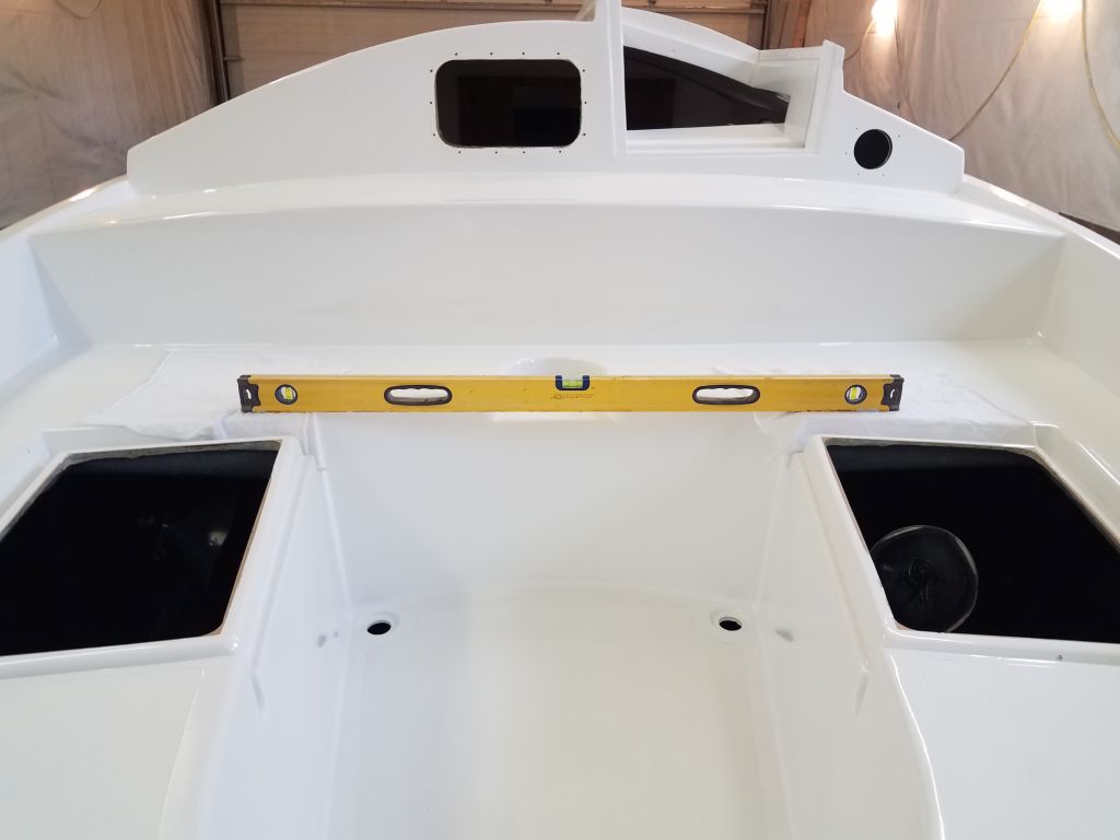
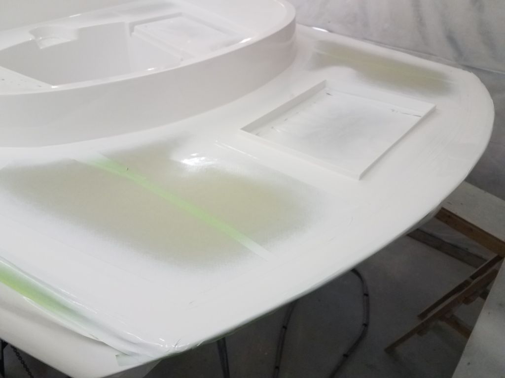
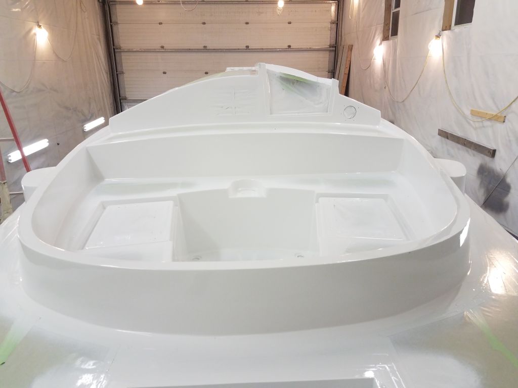
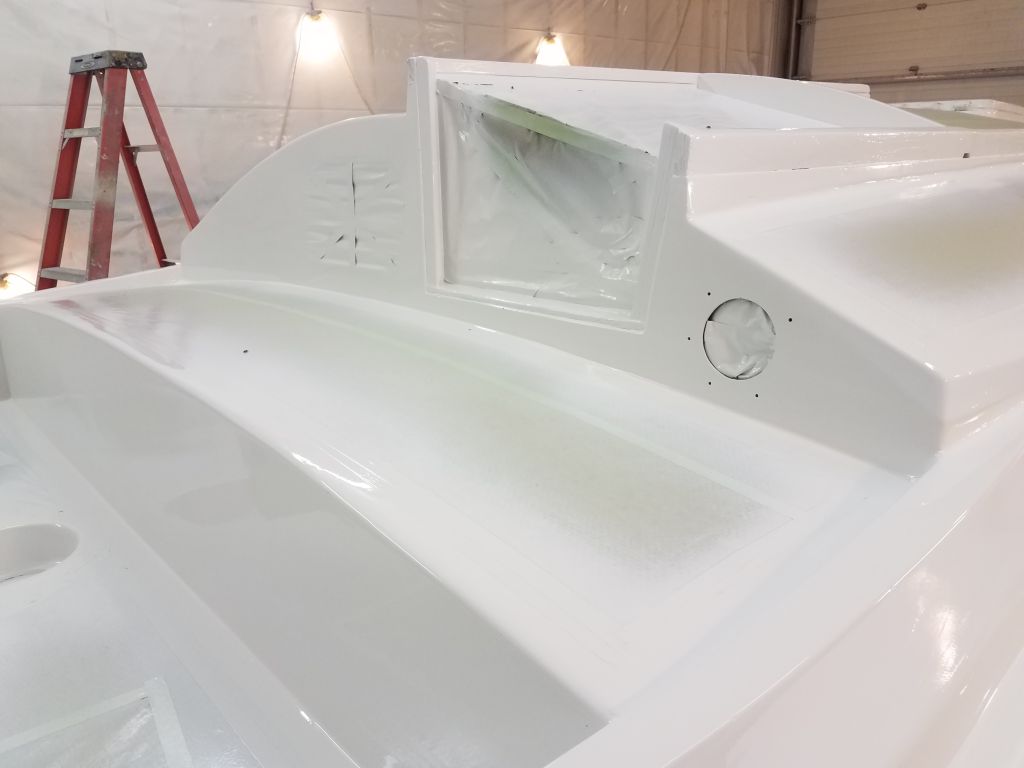
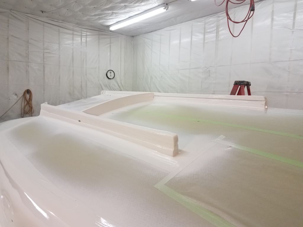
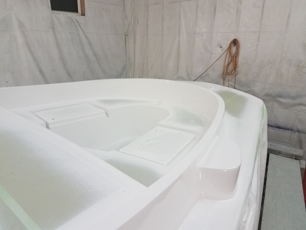
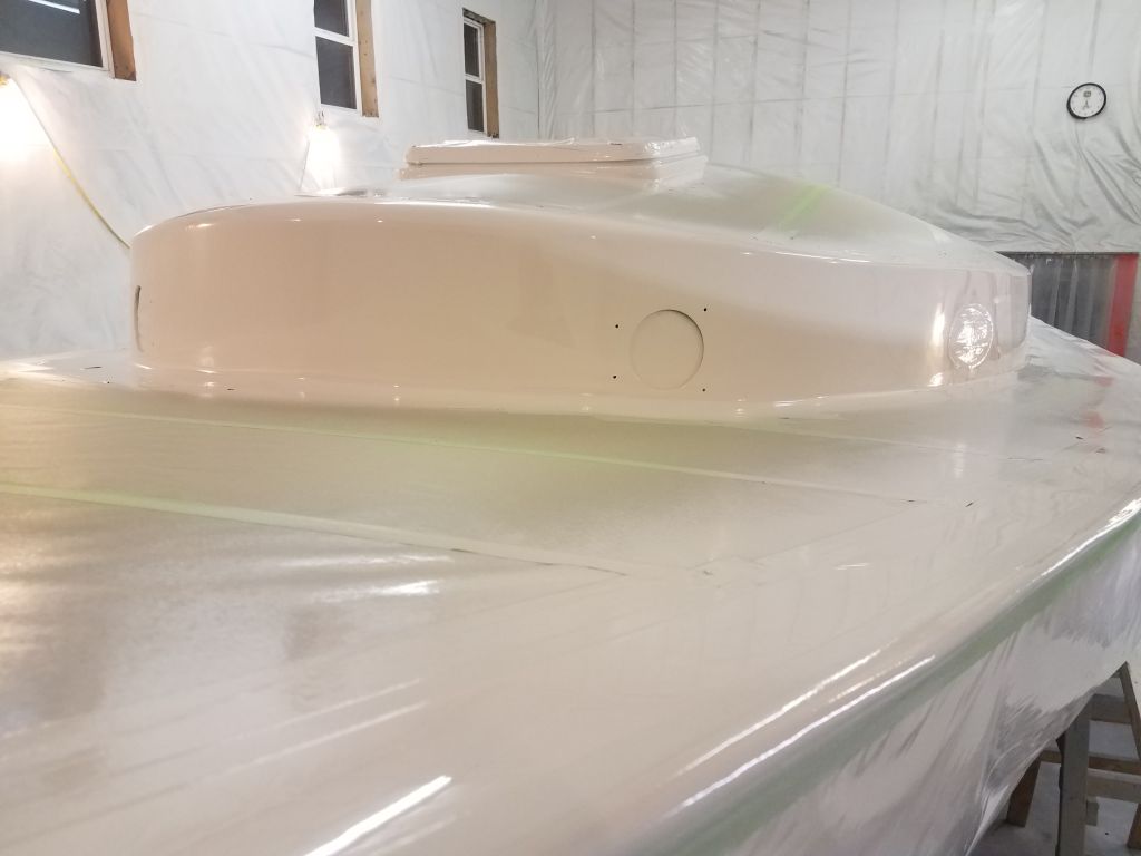
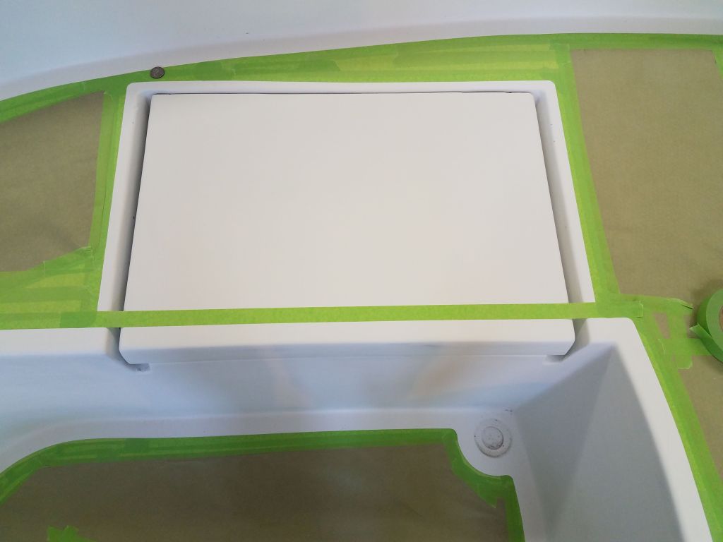
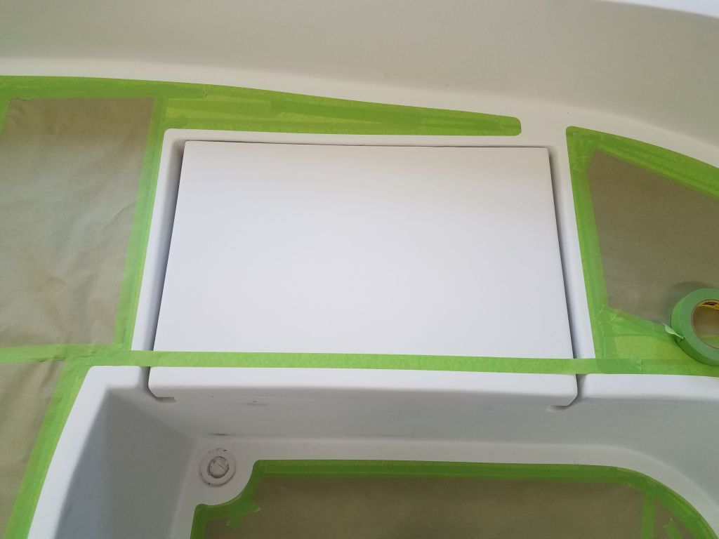
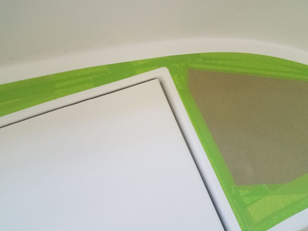
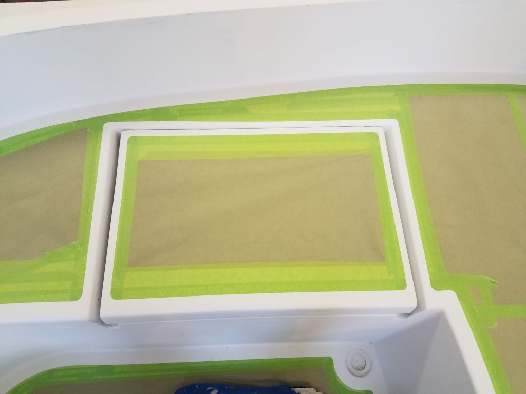
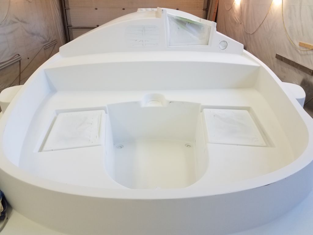
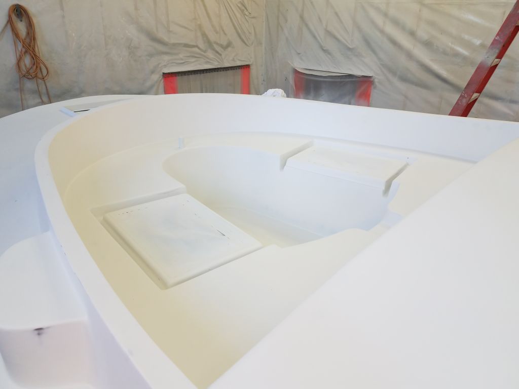
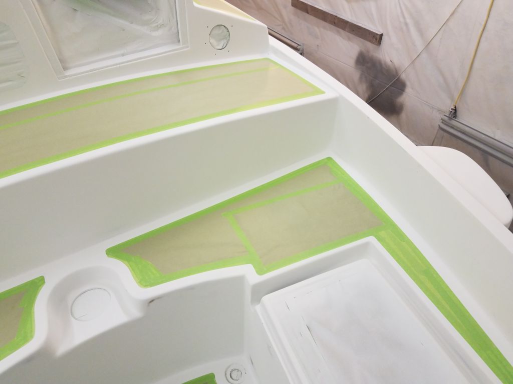
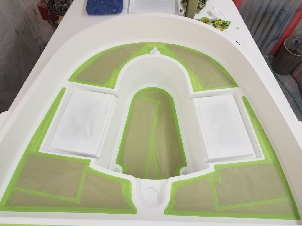
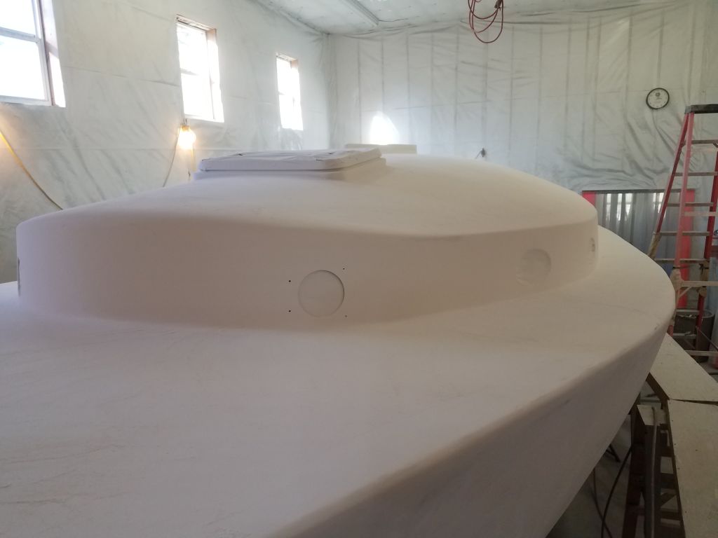
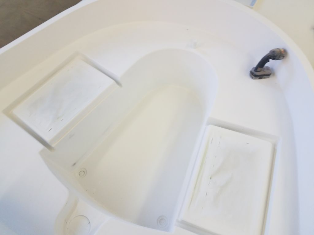
I temporarily set the two cockpit locker lids in place so I could align the masking at the inboard edges with the existing borders on each side.
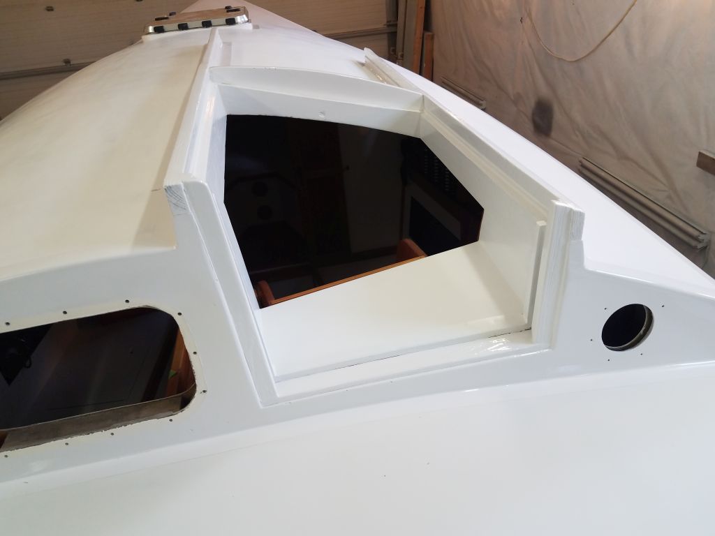
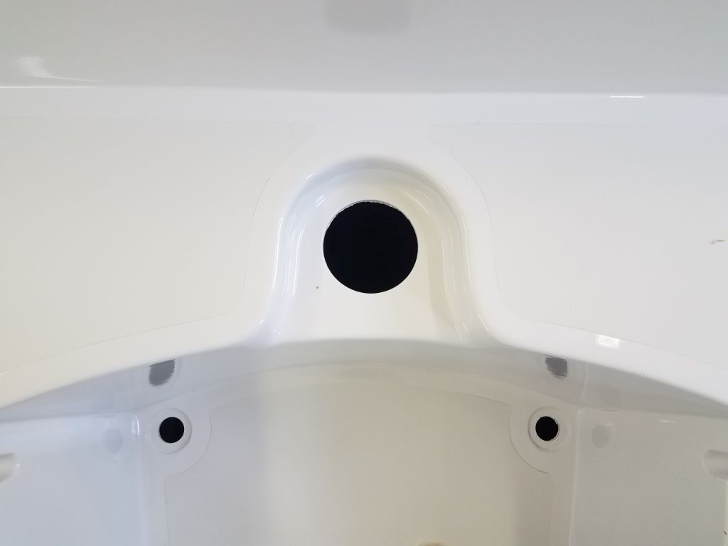
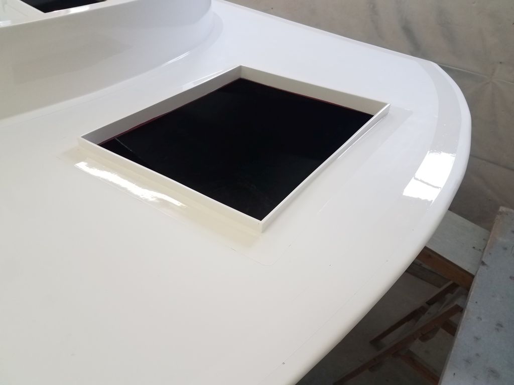
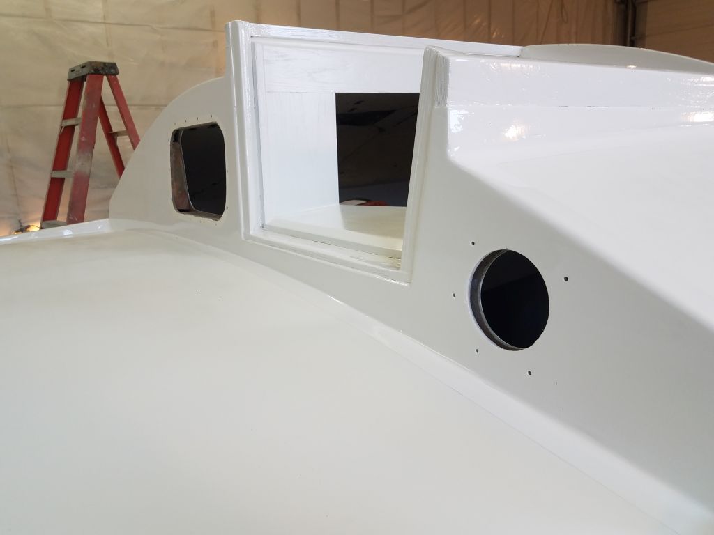
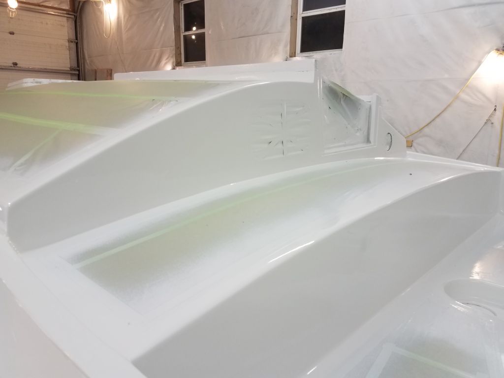
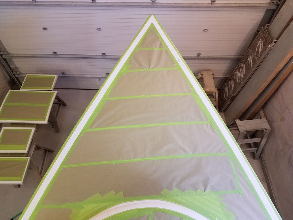
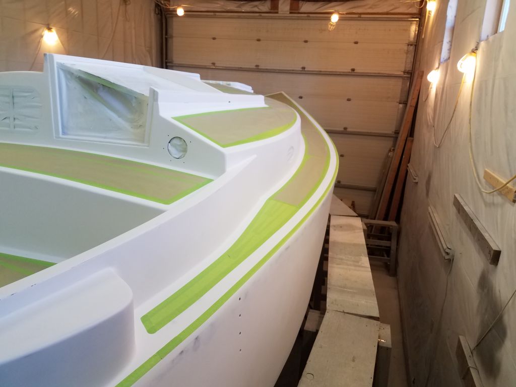
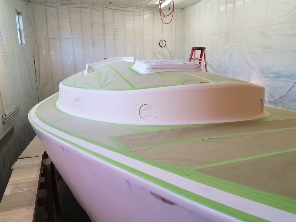
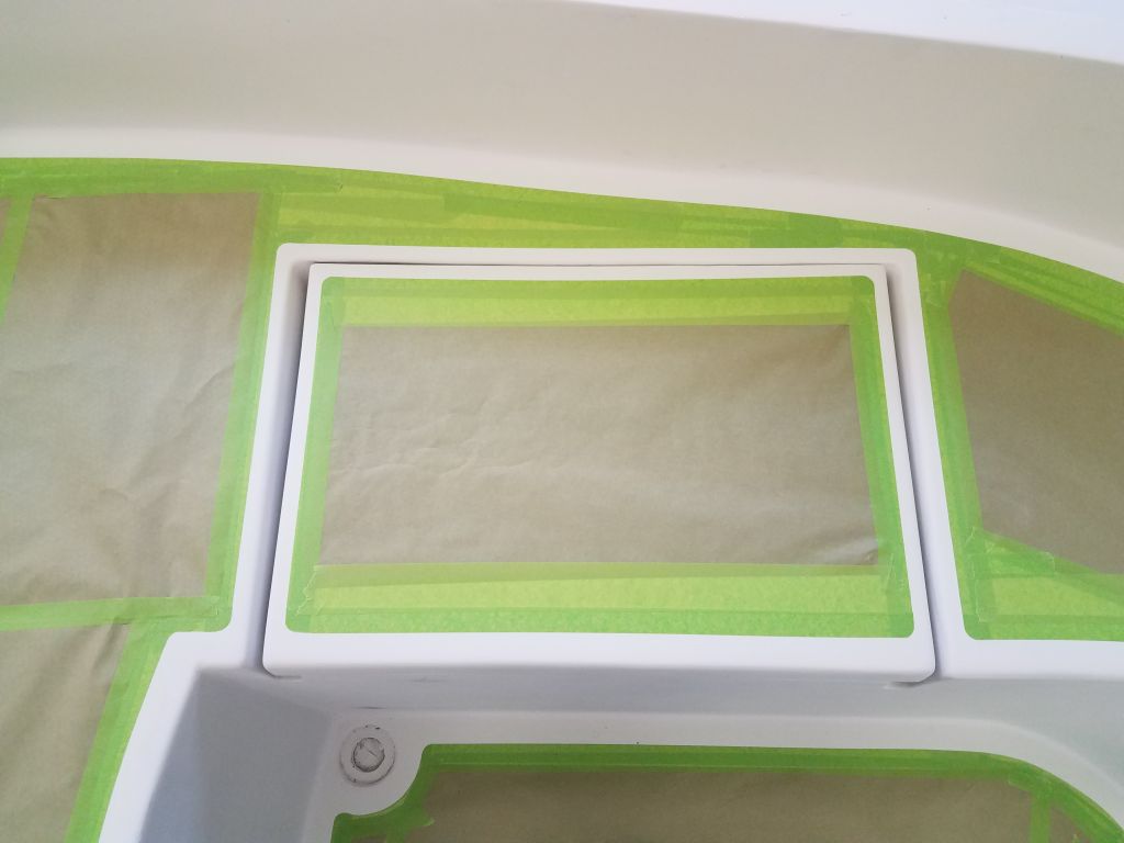
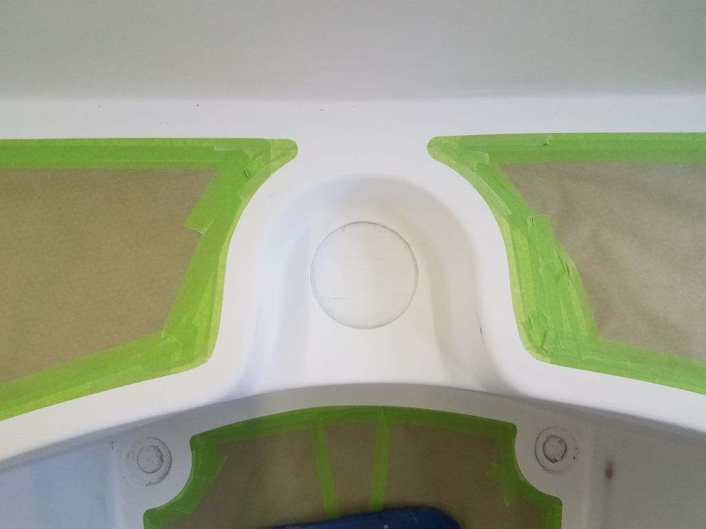
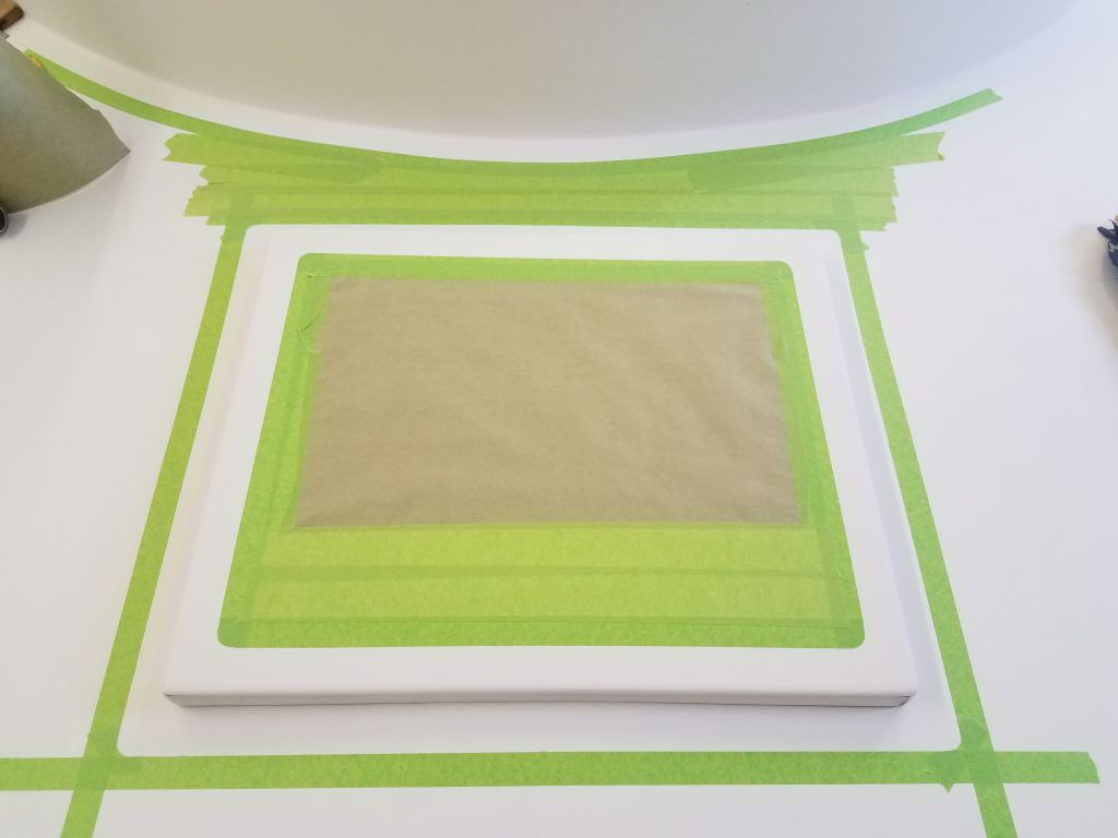
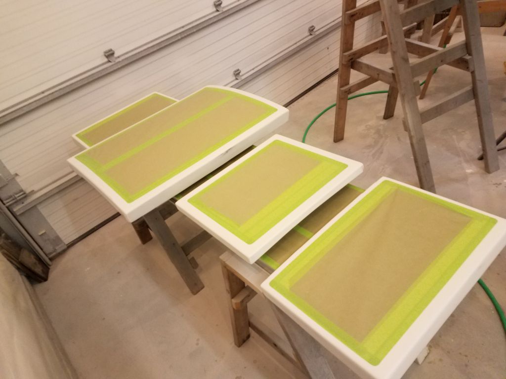
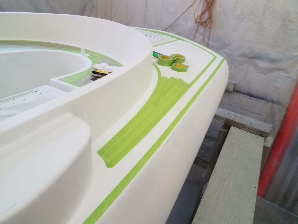
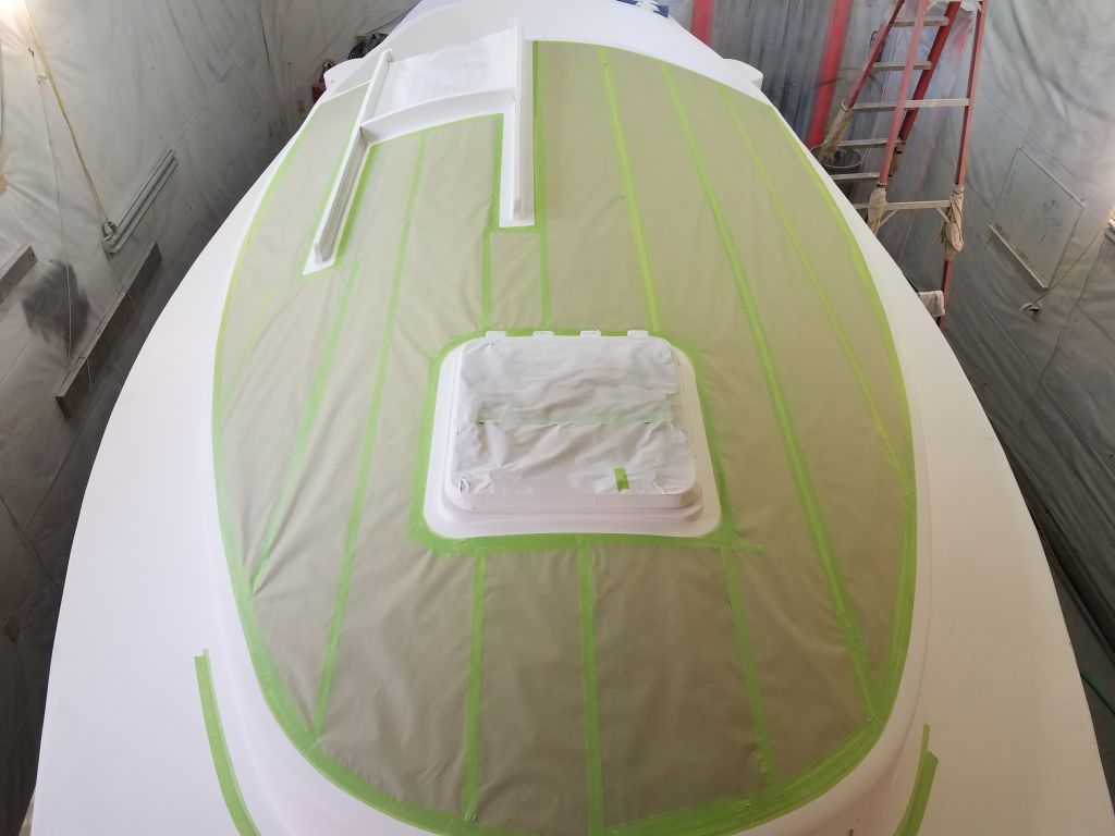
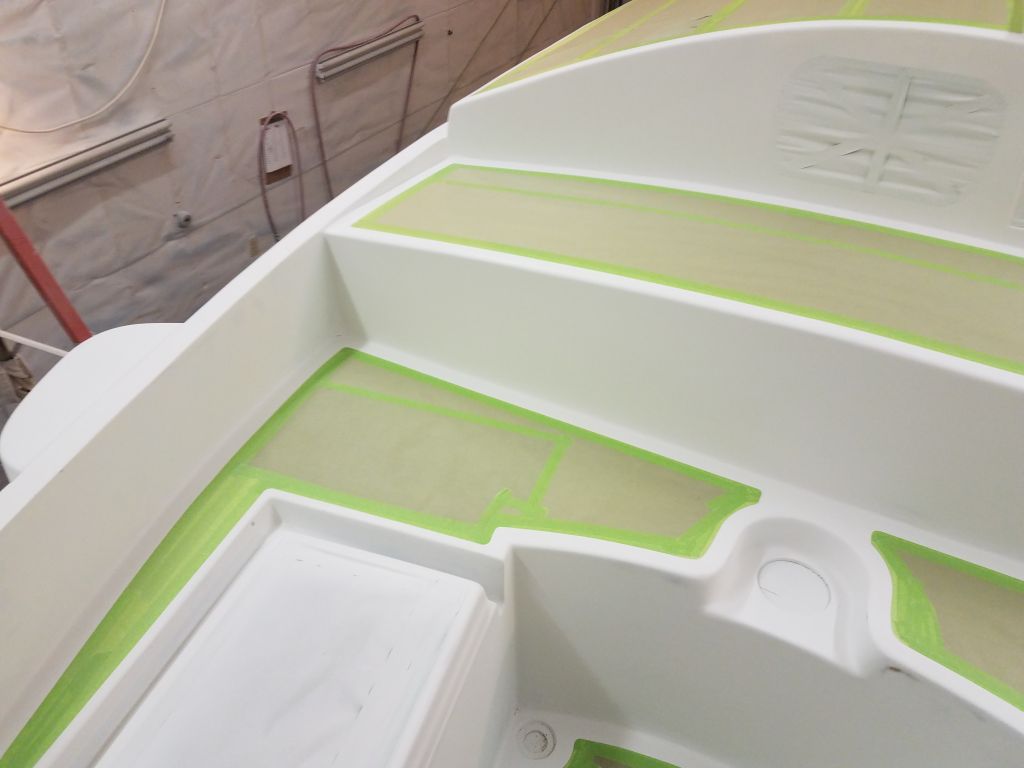
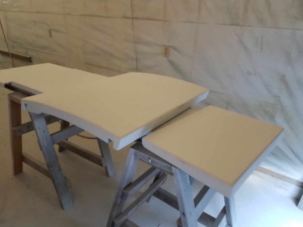
From there, I masked off the remainders of the hatches and covered the field areas with paper. Here, as on the adjacent deck borders, I used a 3/4″ border width on the hatch so that the total border area around each hatch seam would total 1-1/2″ and be visually consistent with the other deck borders. While I was at it, I slightly changed the way I’d masked off the cockpit outboard of the hatches, running the tape continuously through the narrowest part of the area rather than leaving a gap as I had originally. Similarly, I also massaged the masking around the compass recess at the forward end of the cockpit, bringing the end result more in keeping with my general masking conventions.
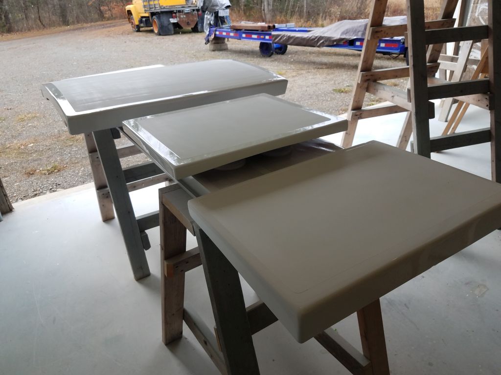
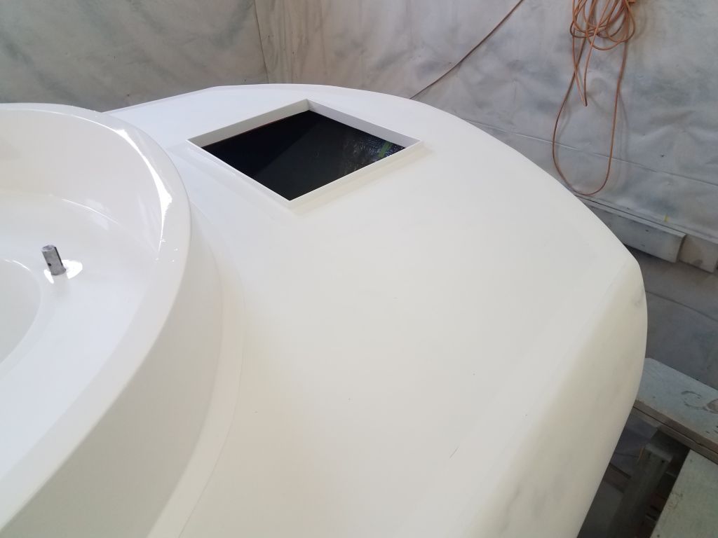
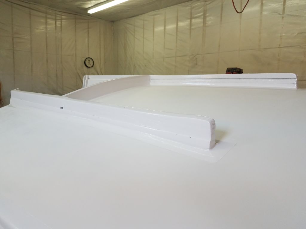
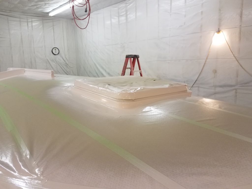
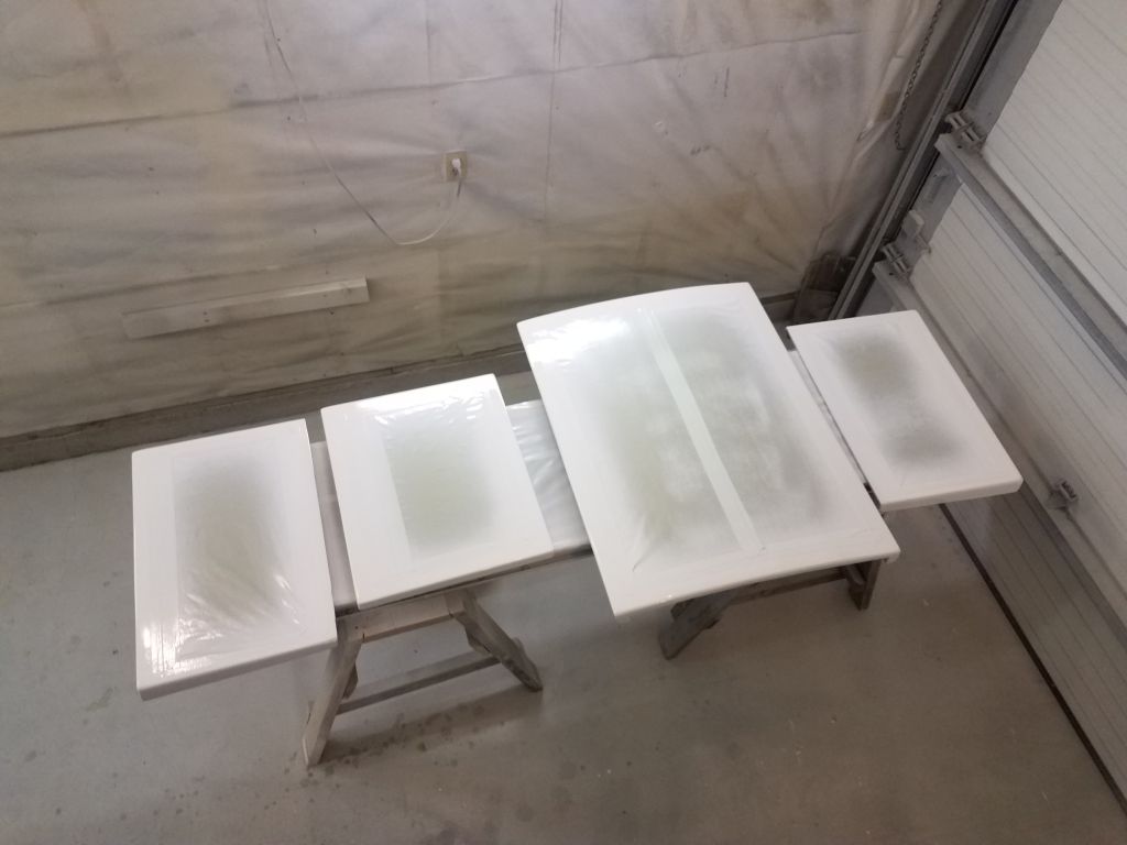
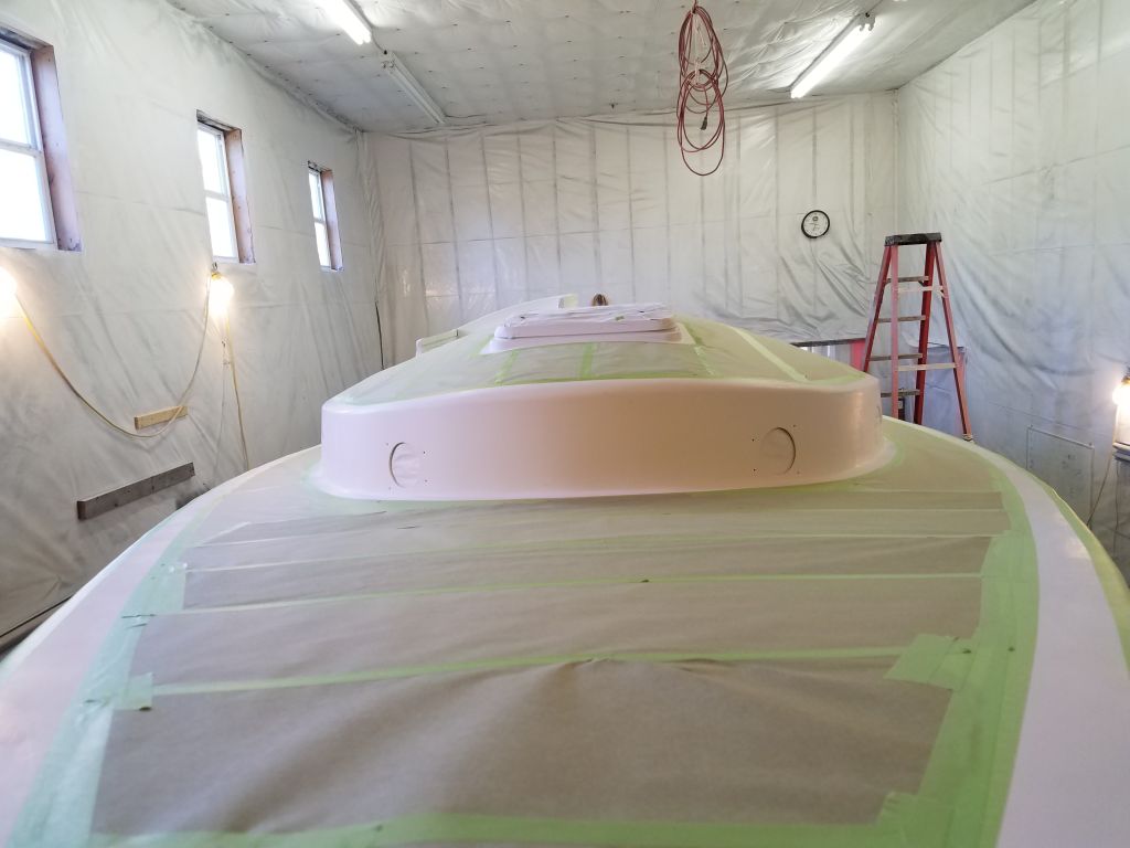
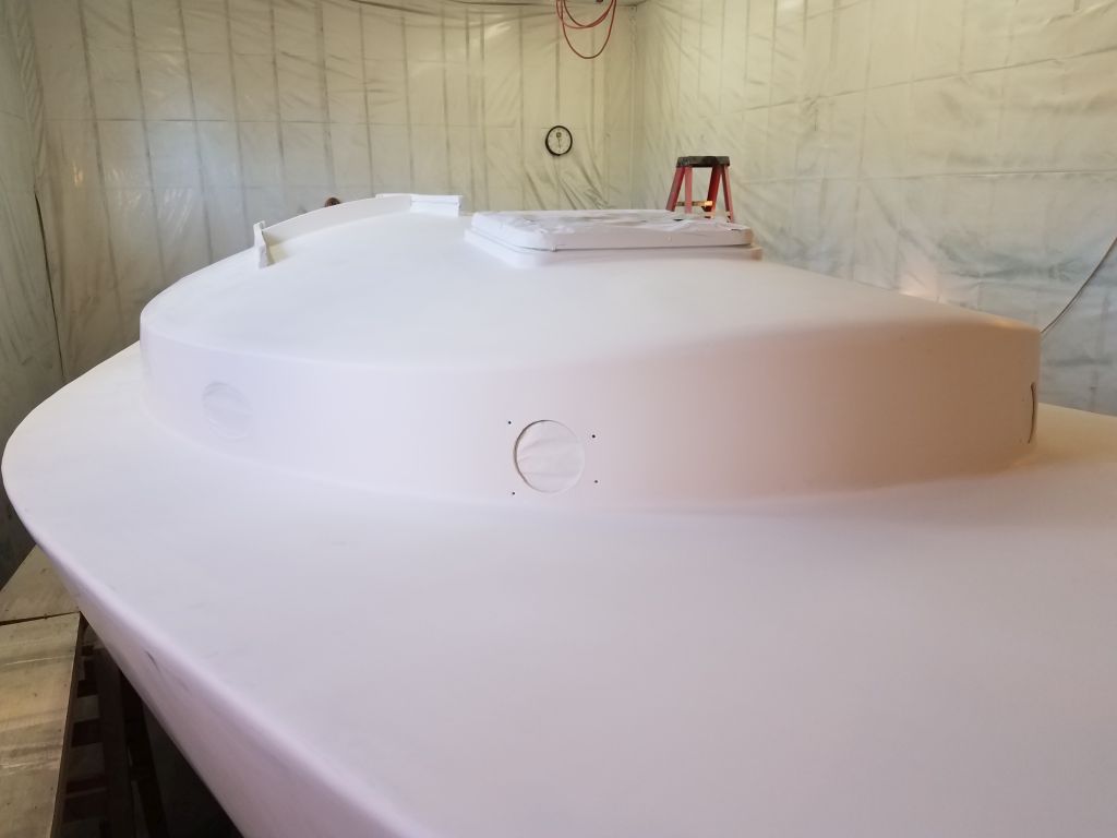
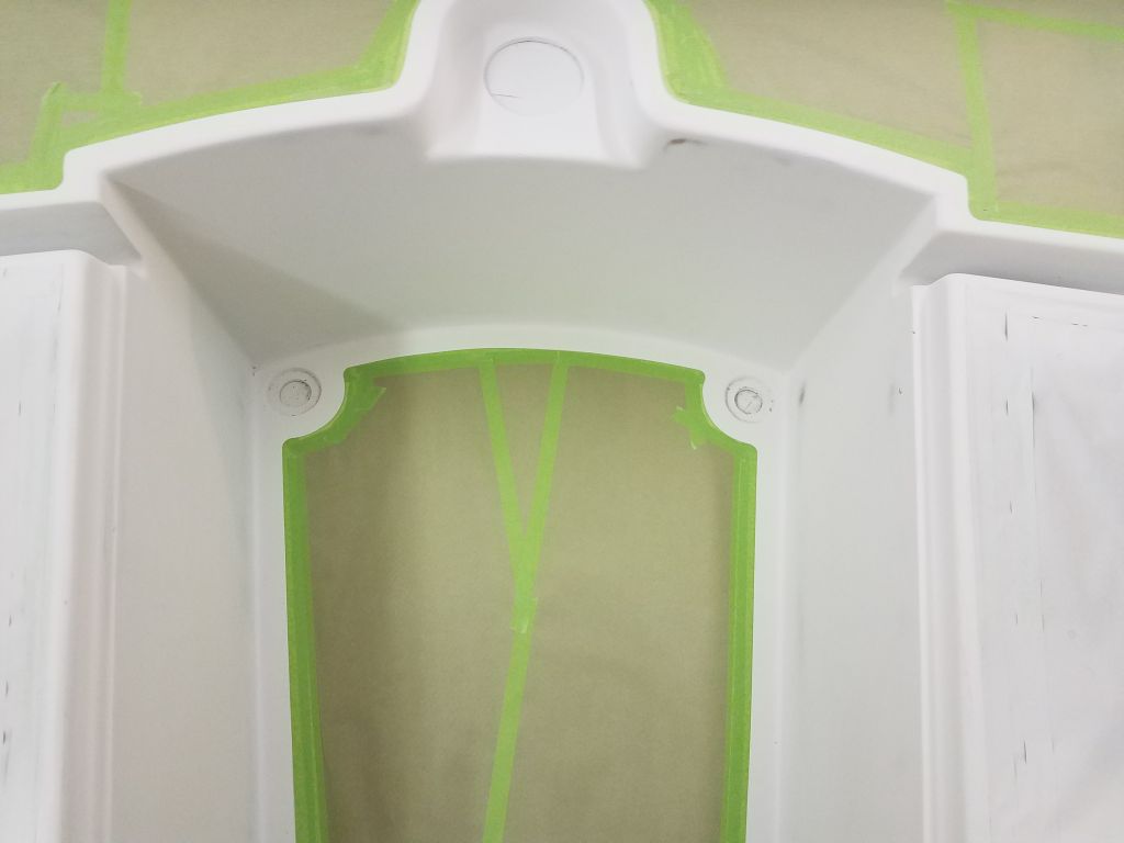
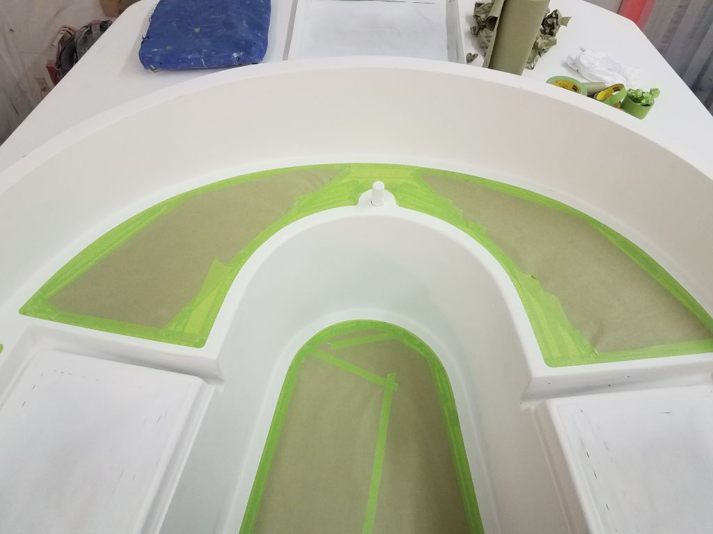
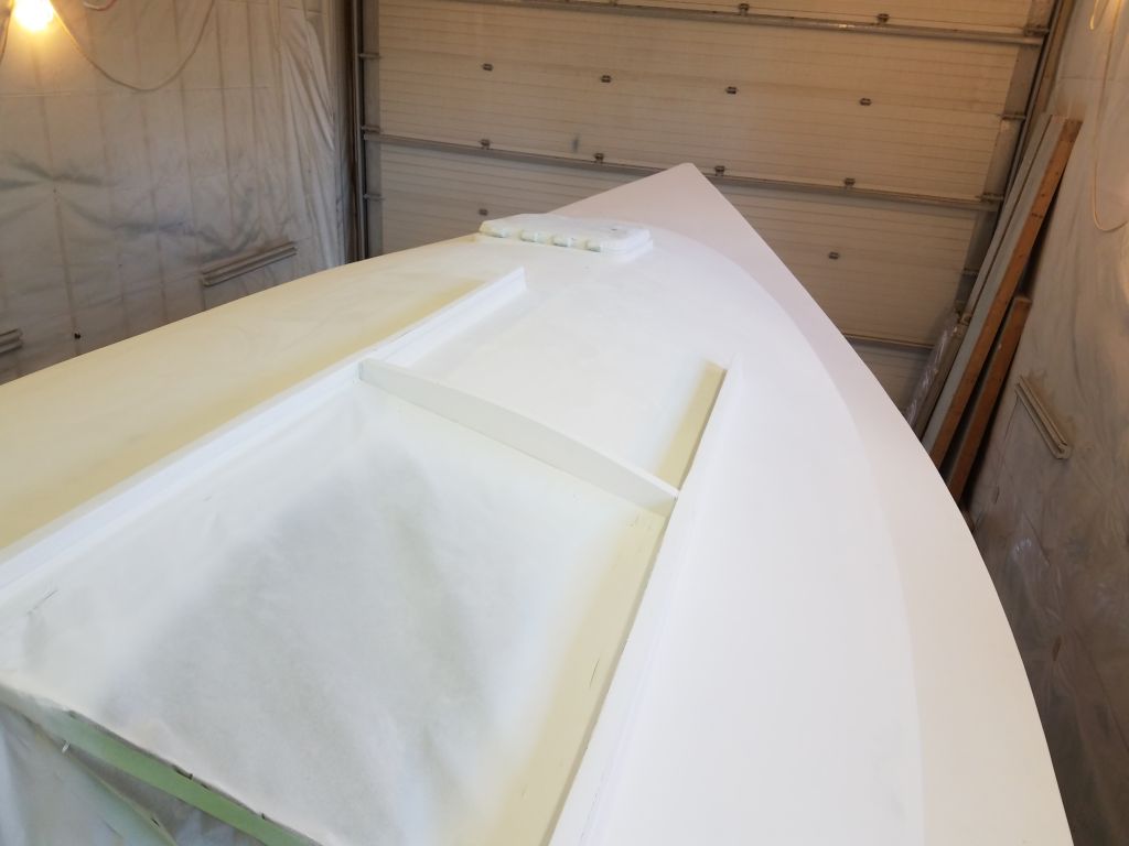
At the lazarette hatch in the poop deck, I temporarily installed the new hatch cover so I could mark my borders from its outside edge, then masked off the area and the hatch accordingly. After returning the three deck hatches to their table on the shop floor, I finished up by masking the companionway hatch.
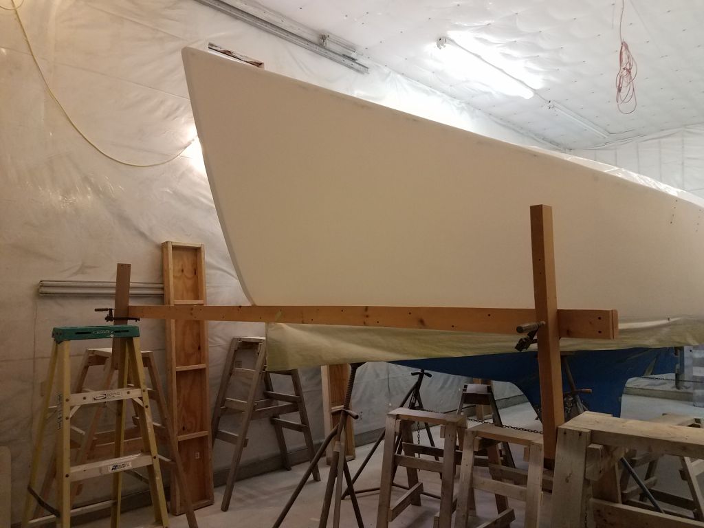
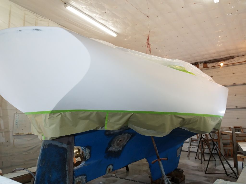
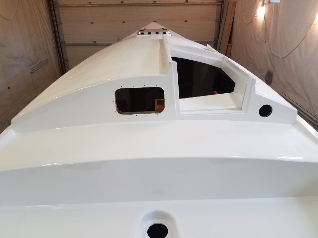
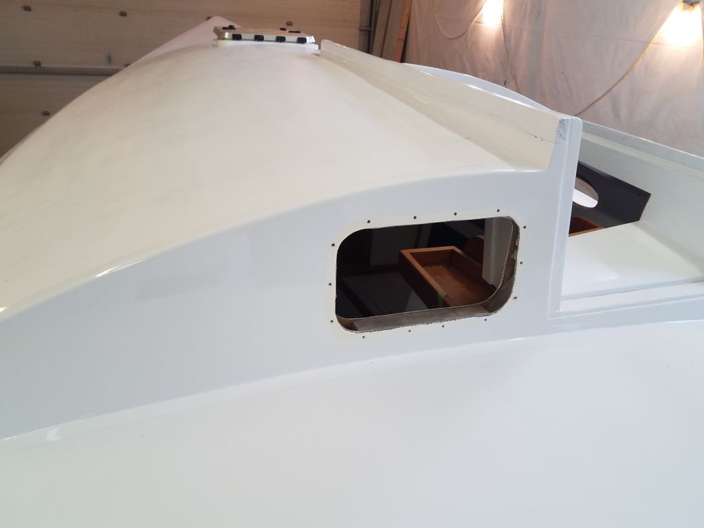
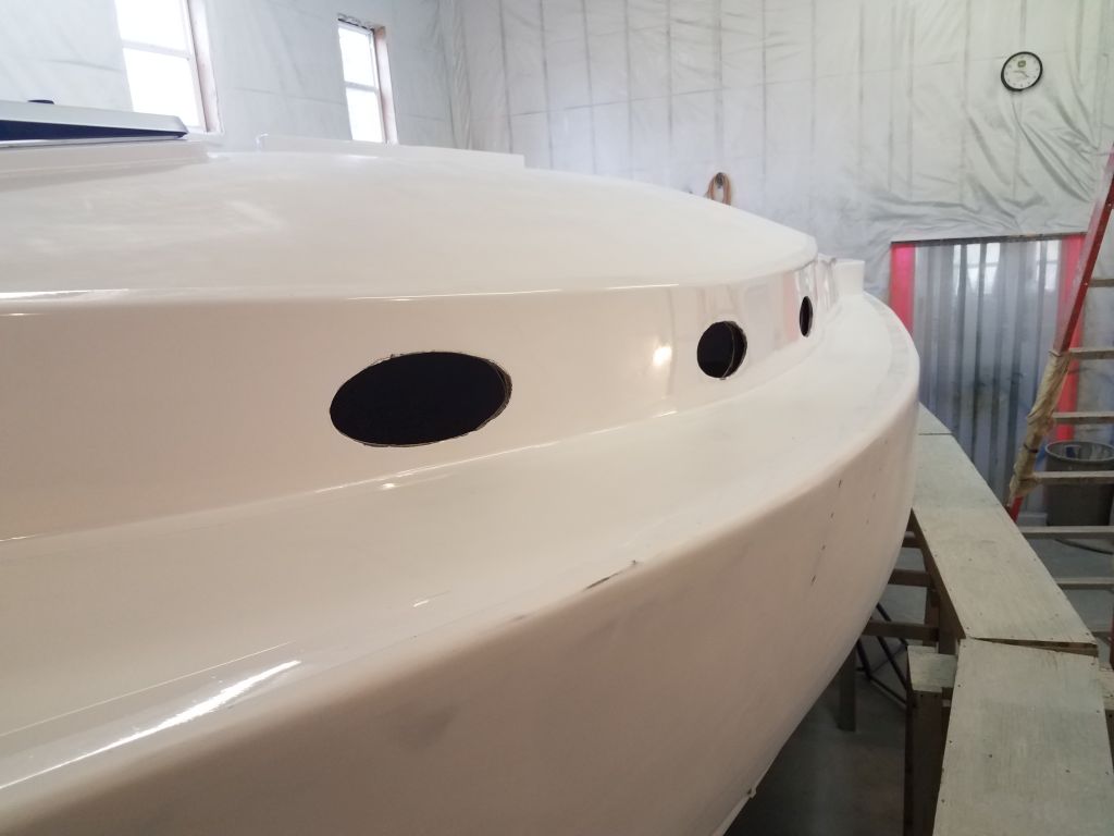
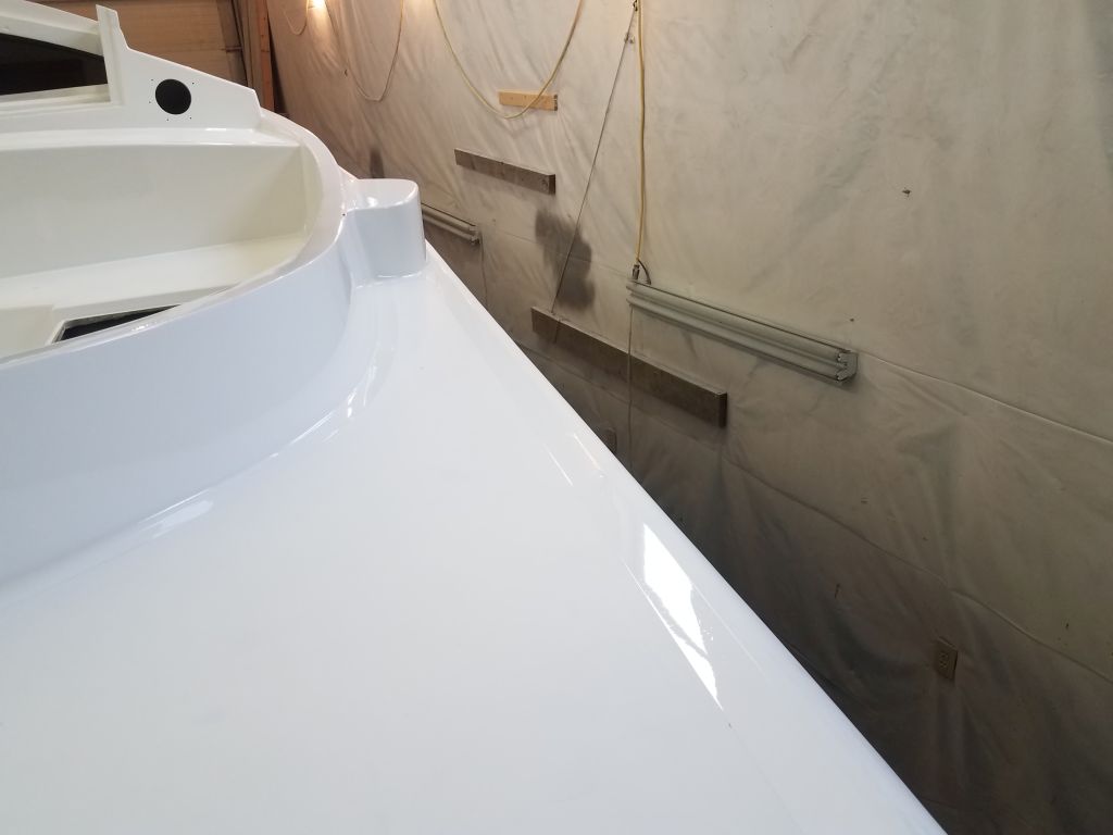
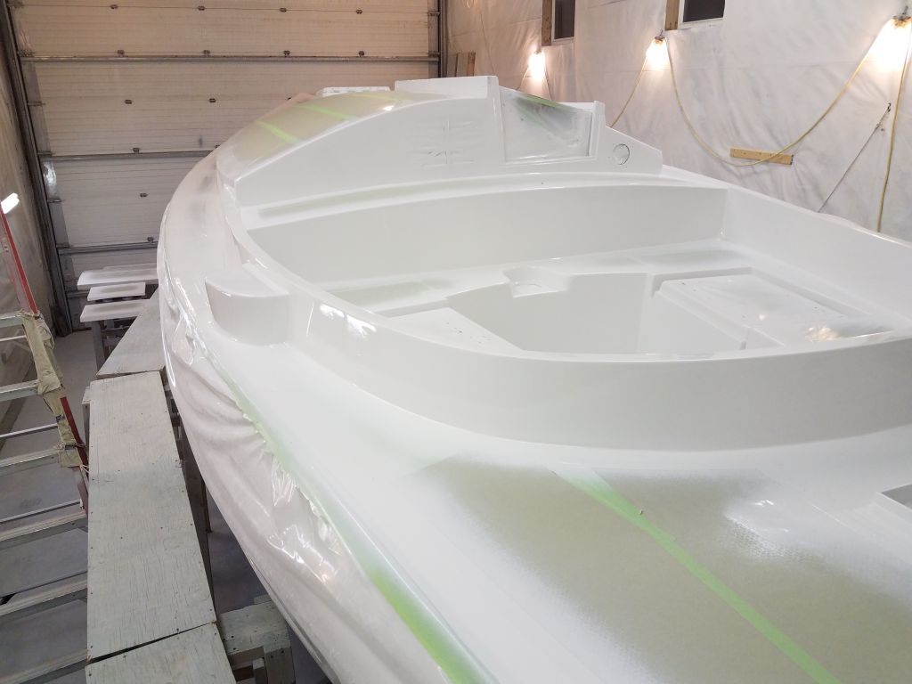
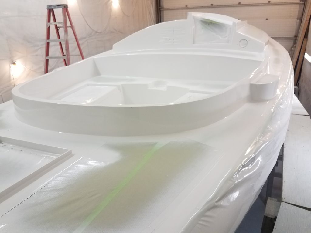
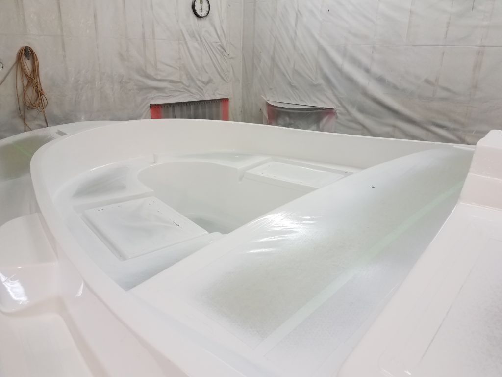
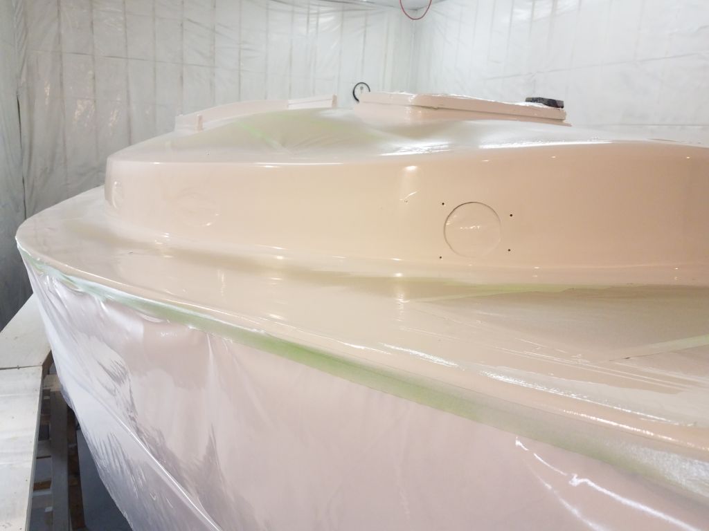
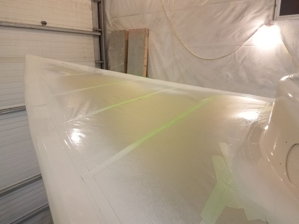
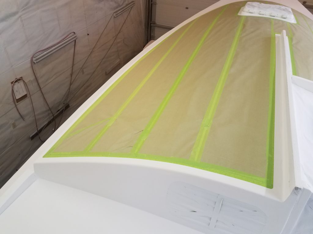
Starting on the port sidedeck, I marked my border along the cabin trunk and coaming, and masked along these lines to define the inboard edge of the deck.
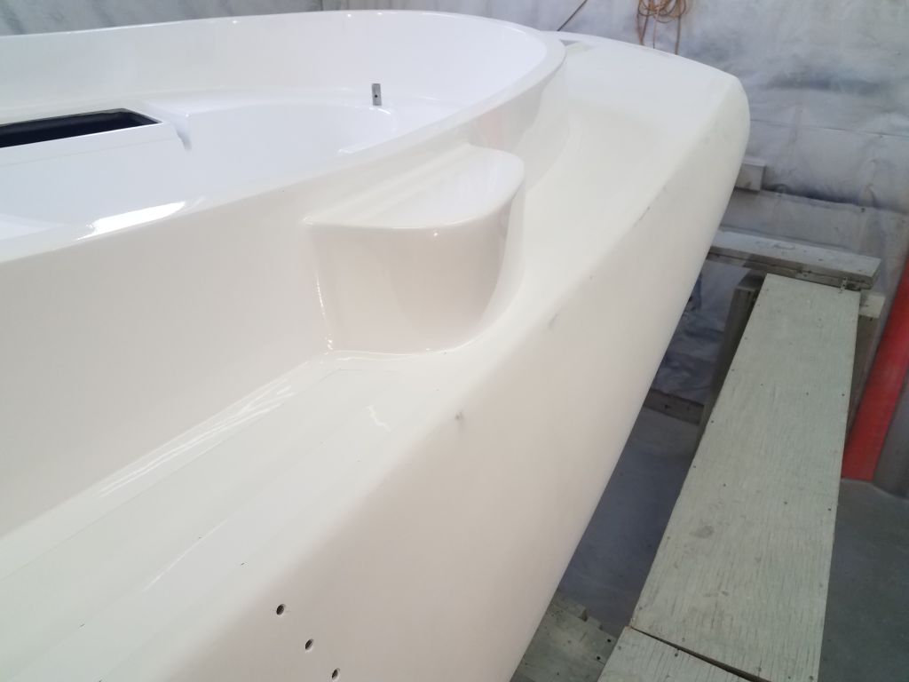
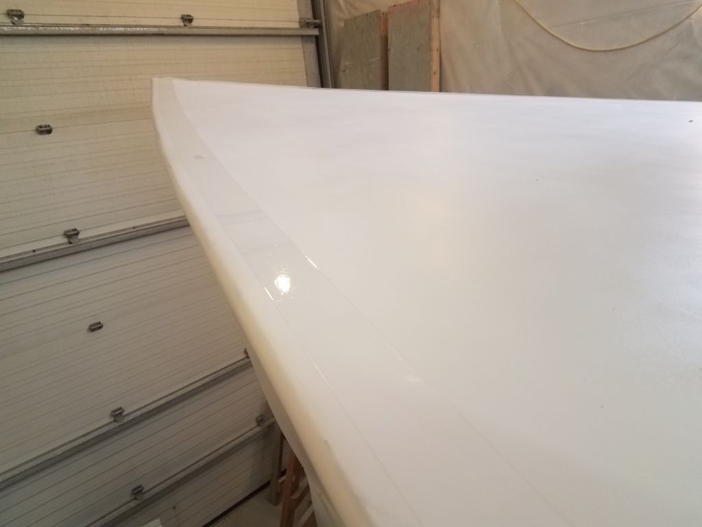
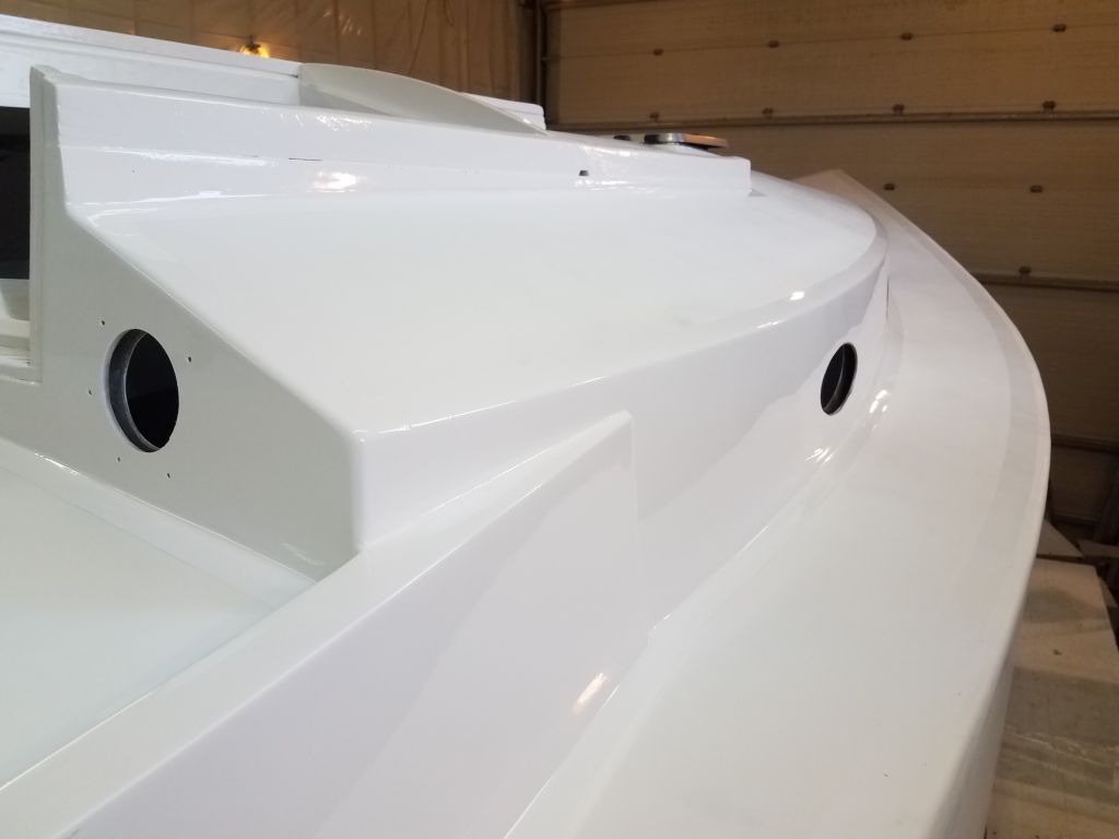
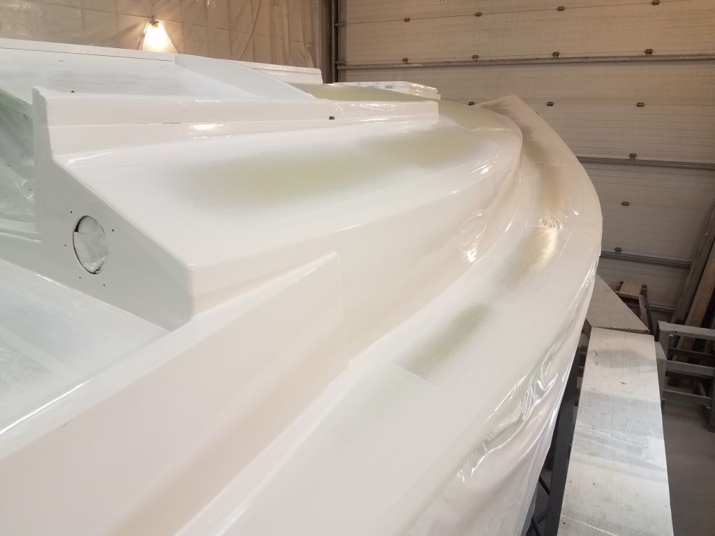
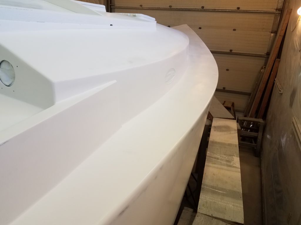
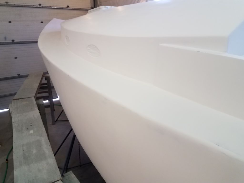
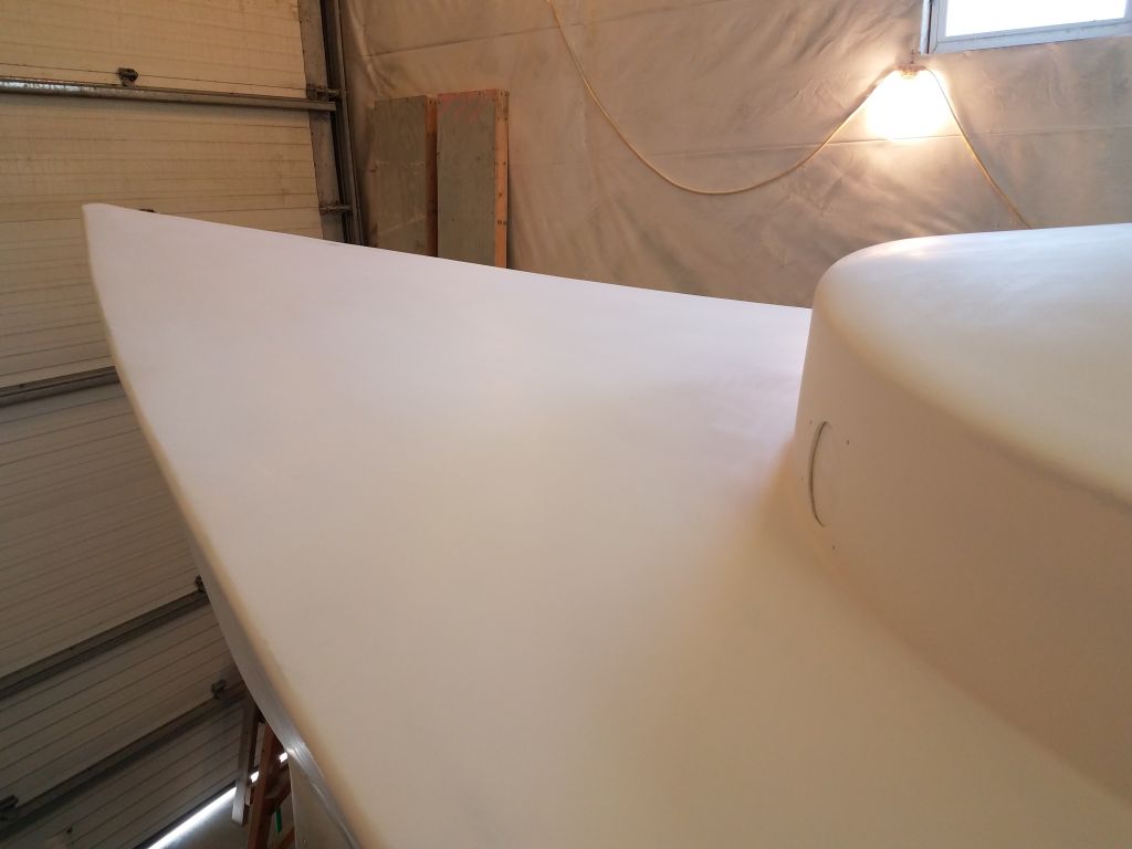
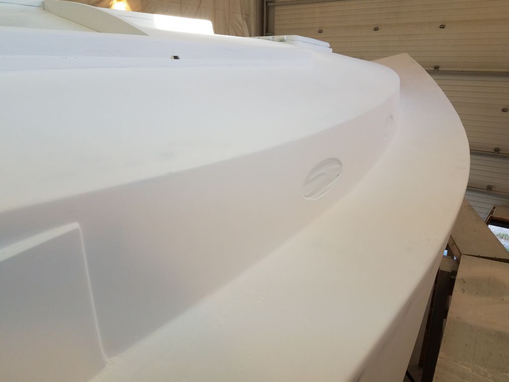
At the outboard edge, I needed to create a similar border and also mark an edge against which I’d mask off the hull during the deck work, and coming up with the plan for this masking was a bit more of a challenge. The key factors I had to consider here included the width of the as-yet nonexistent new toerail, plus the seamless rounded profile of the hull/deck joint, with its variable geometry thanks to the flare of the hull (forward) and tumblehome (aft).
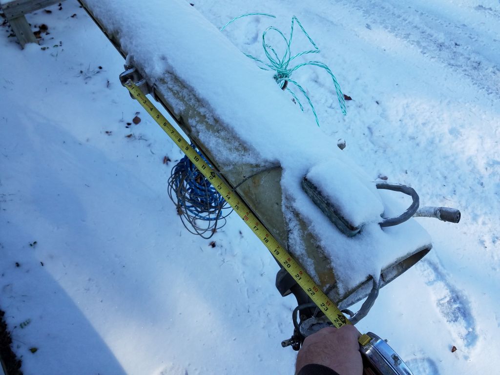
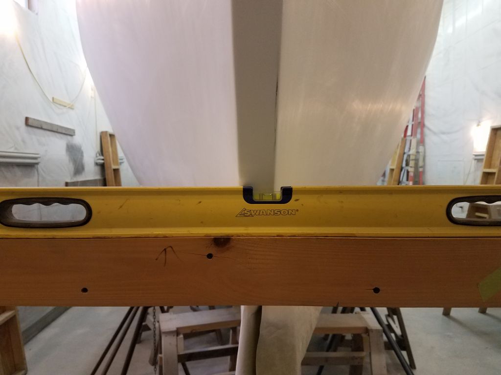
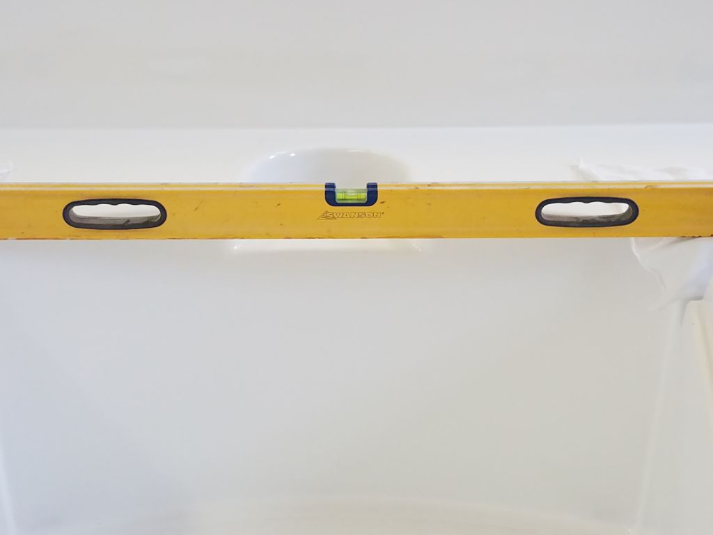
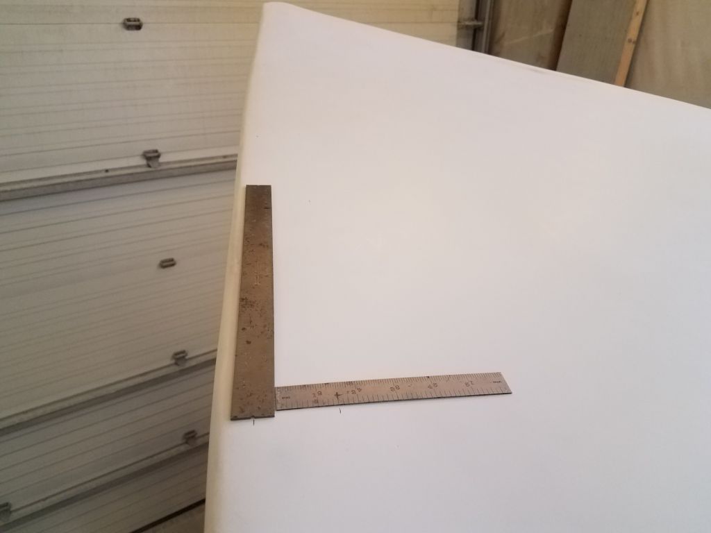
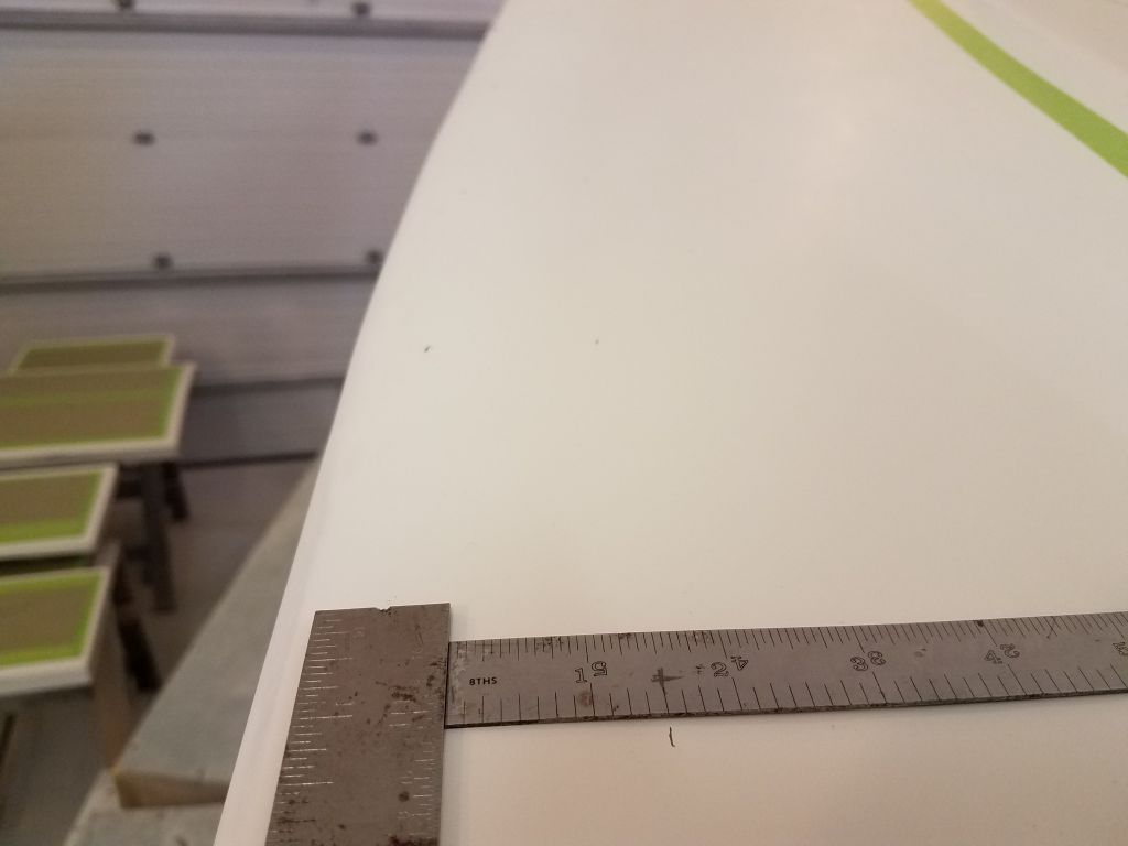
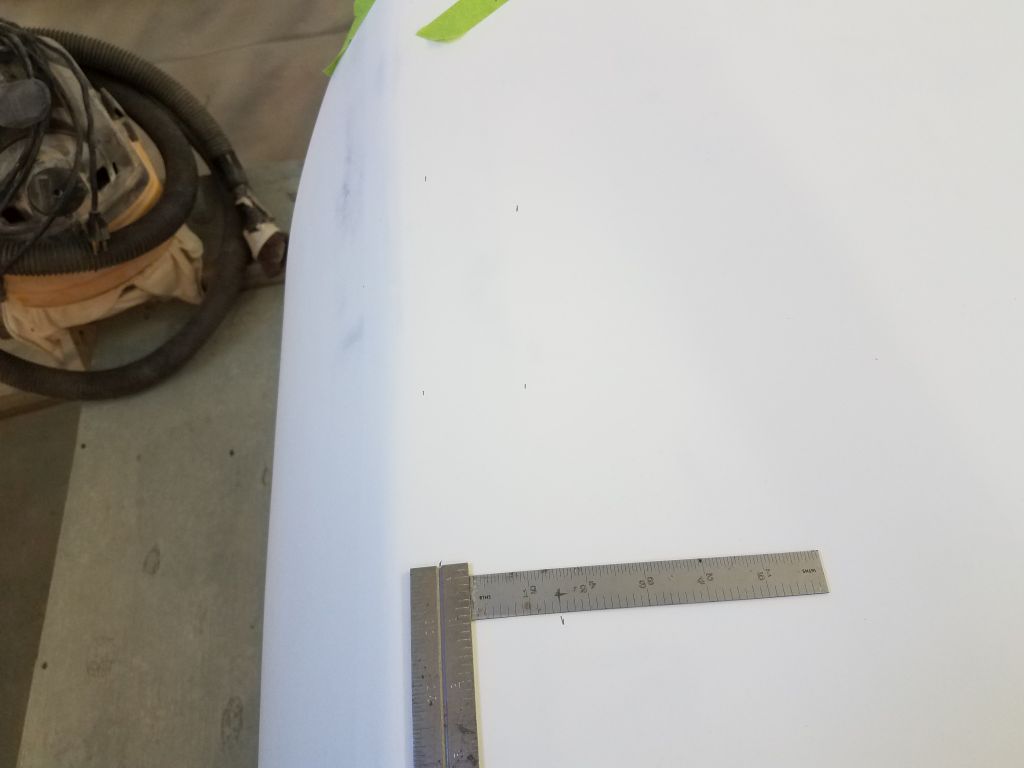
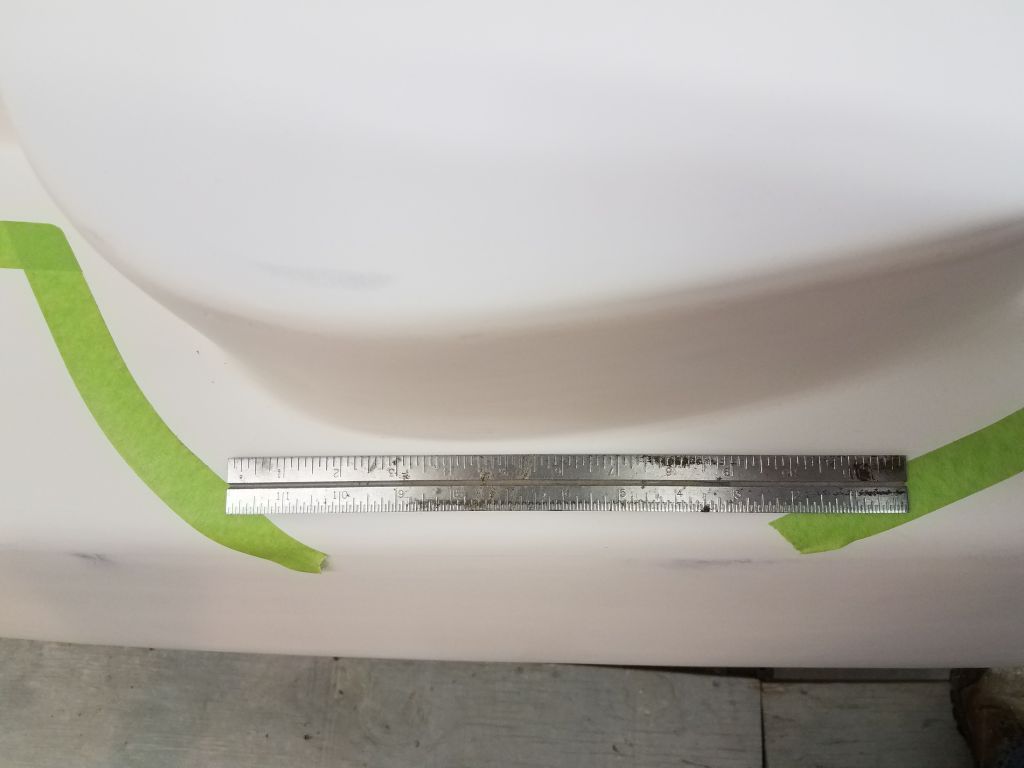
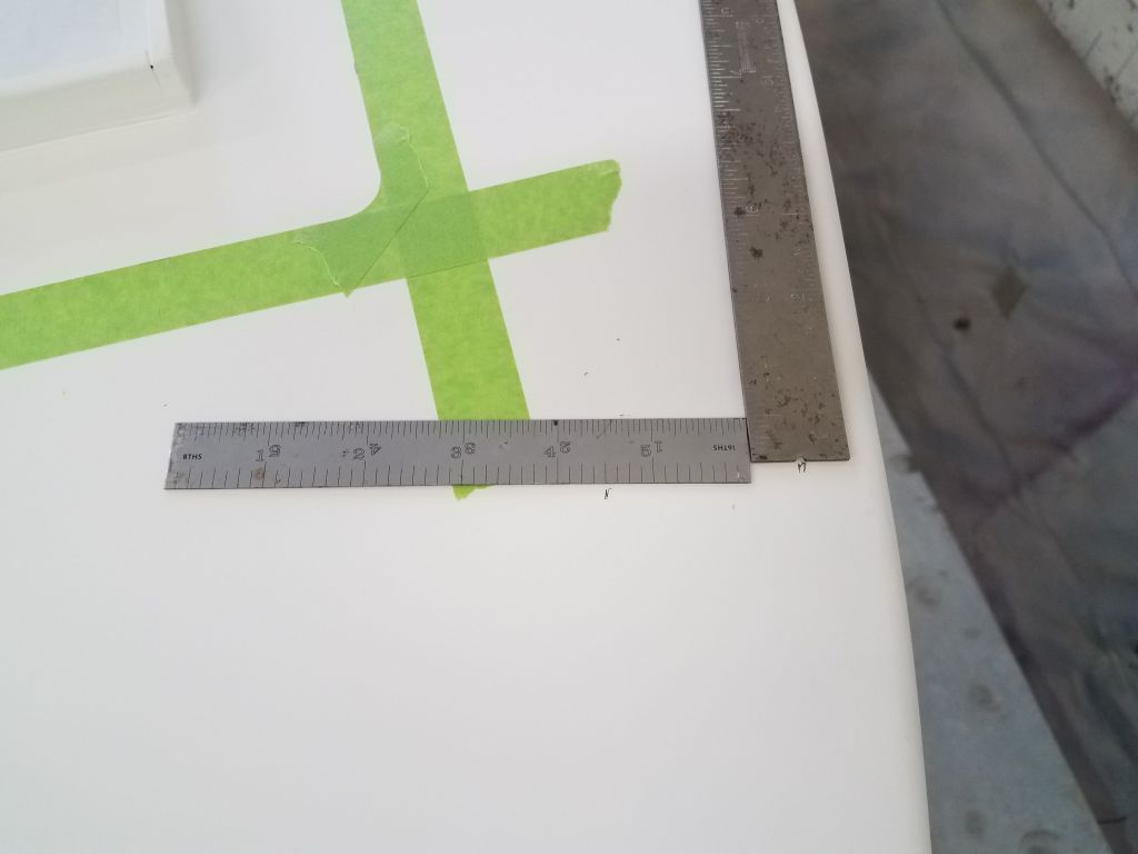
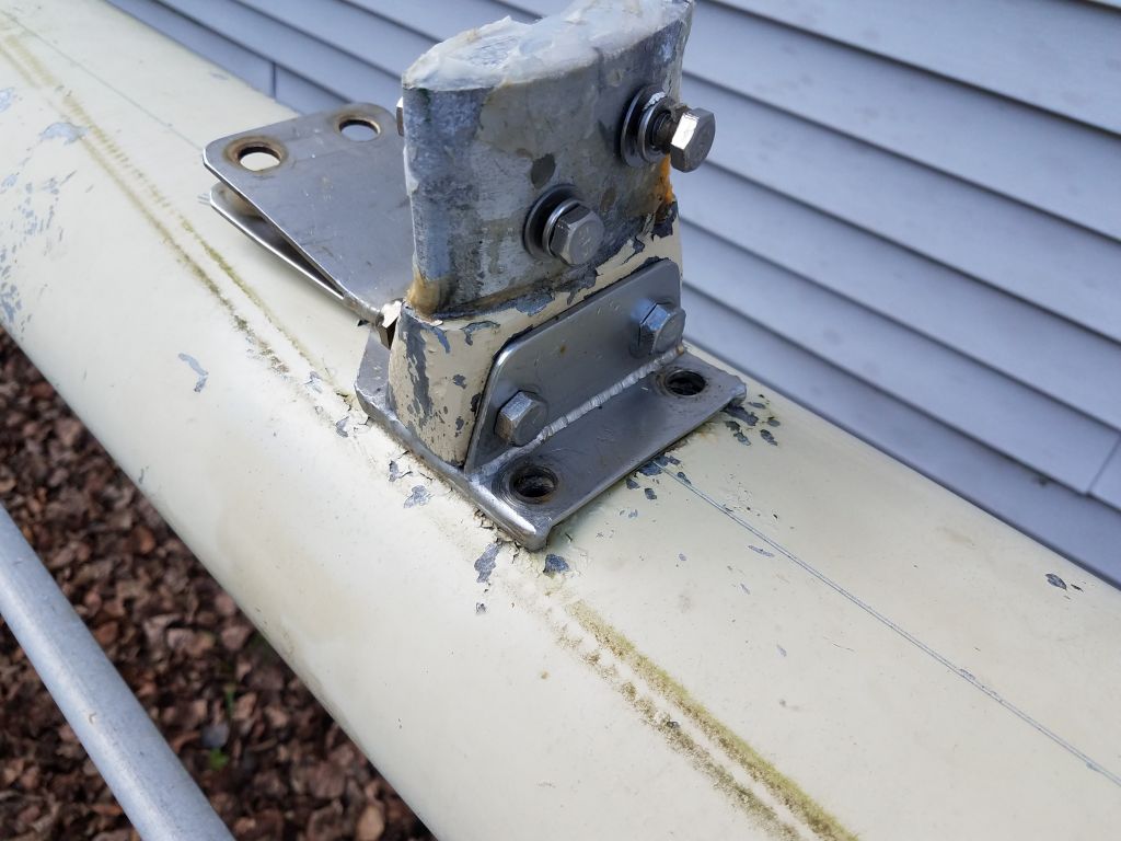
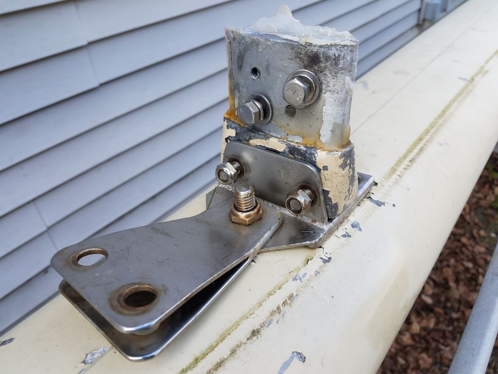
The toerail width was more or less unalterably determined by the space outboard of the winch islands, through which space the rail would need to pass cleanly. I thought I’d reserved a section or two of the original toerail, but they were either hiding or I’d thrown them out in a fit of pique during one cleaning binge or another. However, it seemed pretty clear that the available space, allowing for a reveal at the outer edge and just enough space on the inside, was about 1″, same as my steel rule as shown below. Reviewing photos from the boat’s disassembly, I confirmed that that original rail also fit in the same space, and was approximately 1″ wide.
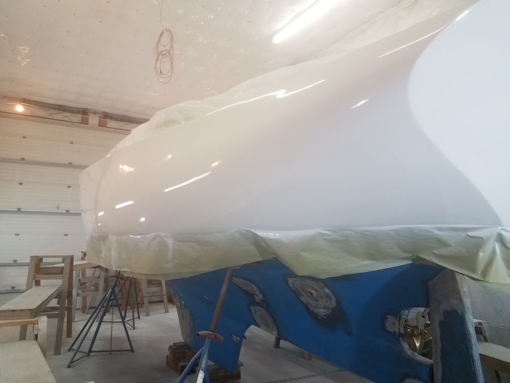
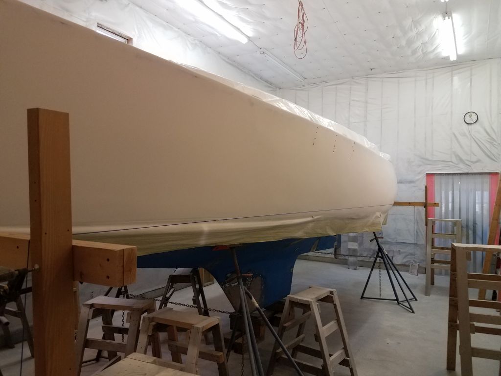
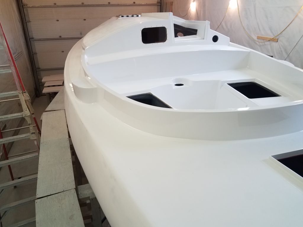
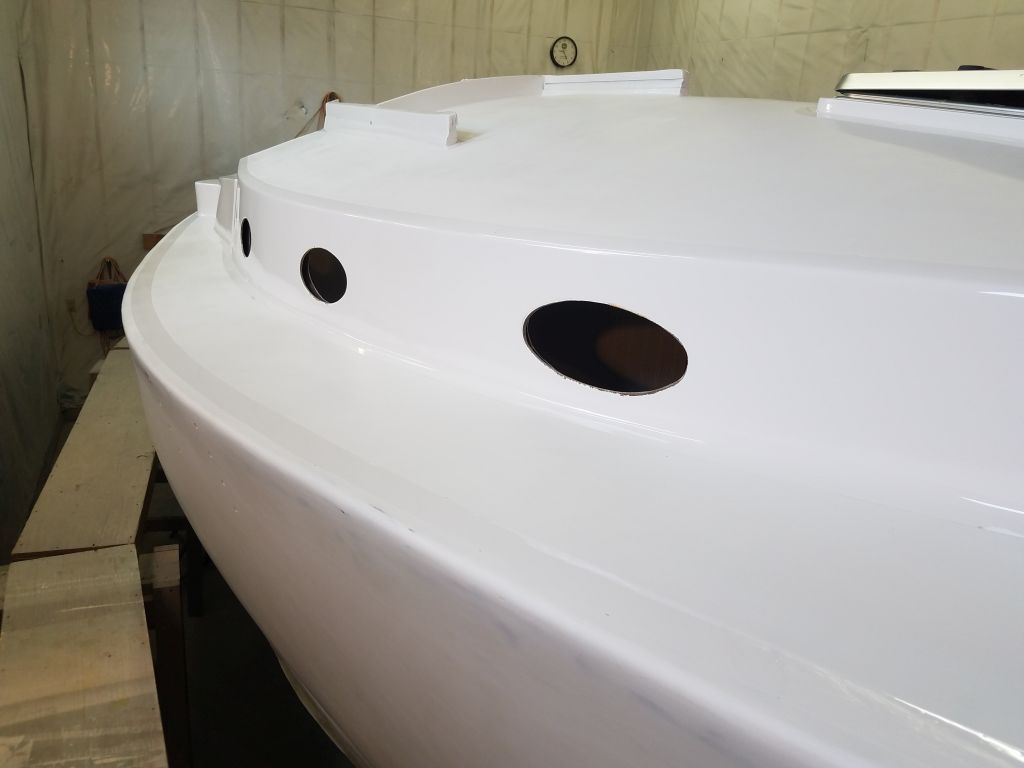
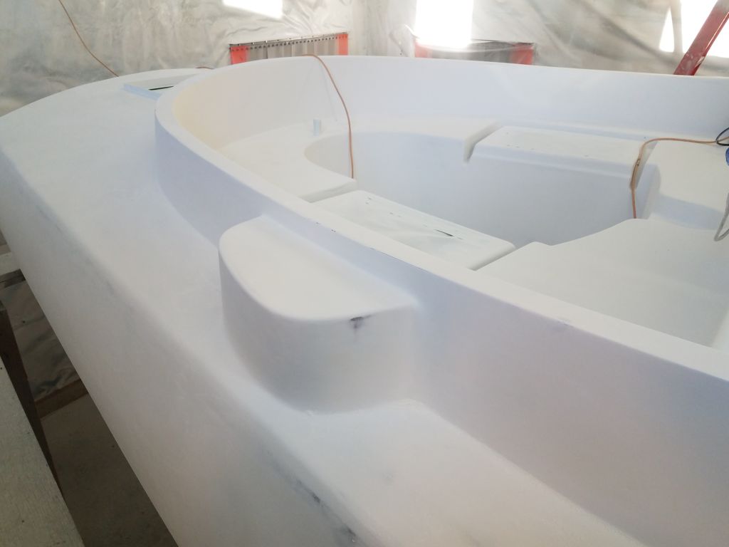
Now I had to translate this into some consistent and workable method of marking and masking the border, which I wanted at 1-1/2″ inside the finished toerail to remain consistent with the other deck borders. Here, the hull shape worked against me, as I tried one or two marking blocks cut to a specific length to try and align and make the marks, but I found the results inconsistent and unworkable, so in the end, I relied on an eyeball approach, which netted the results I wanted more quickly, easily, and accurately than the other things I’d tried. For these initial steps, I was working on the port quarter, a relatively short and defined section tailor-made for experimentation, but also where the most difficult shapes were in play thanks to the significant tumblehome there.
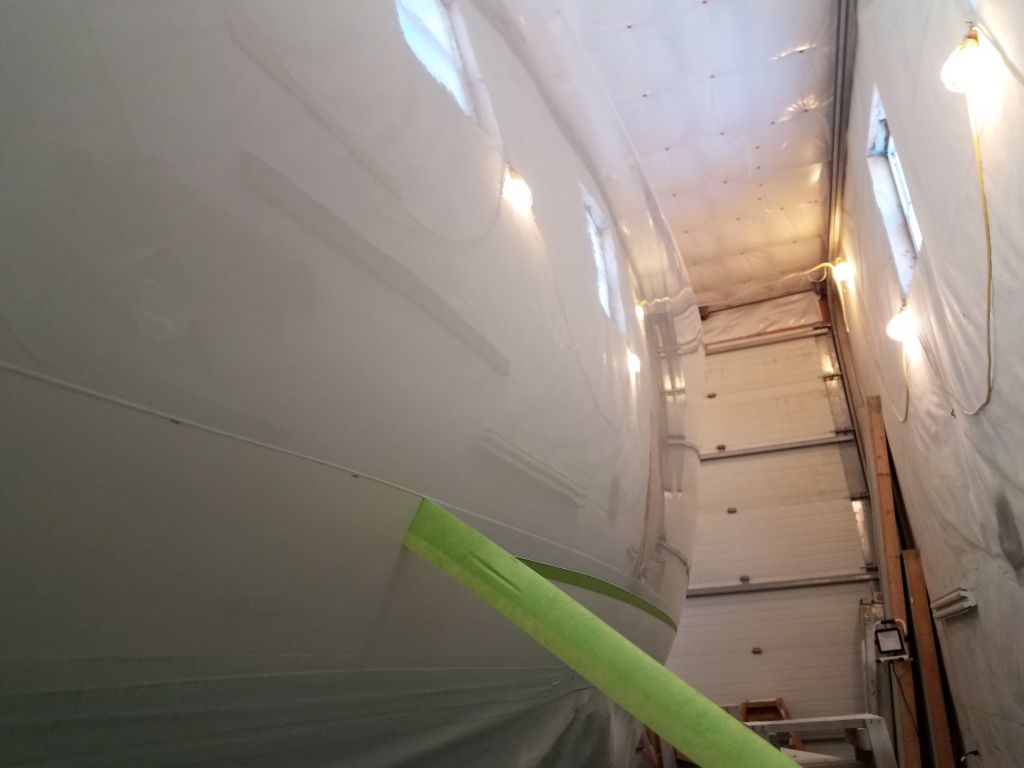
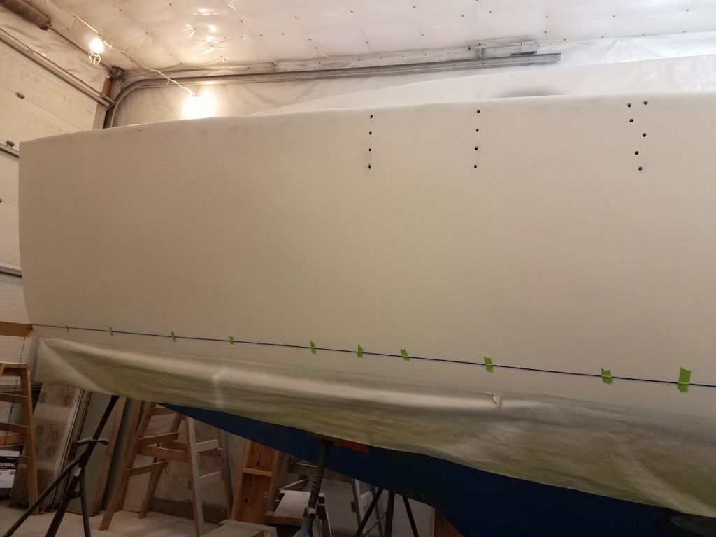
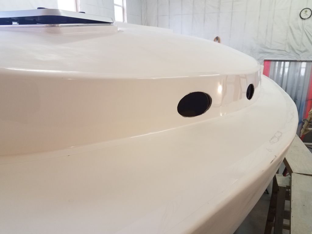
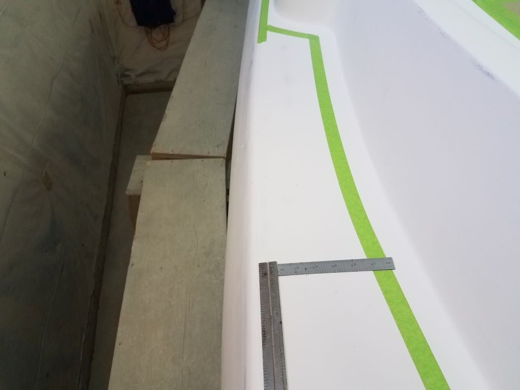
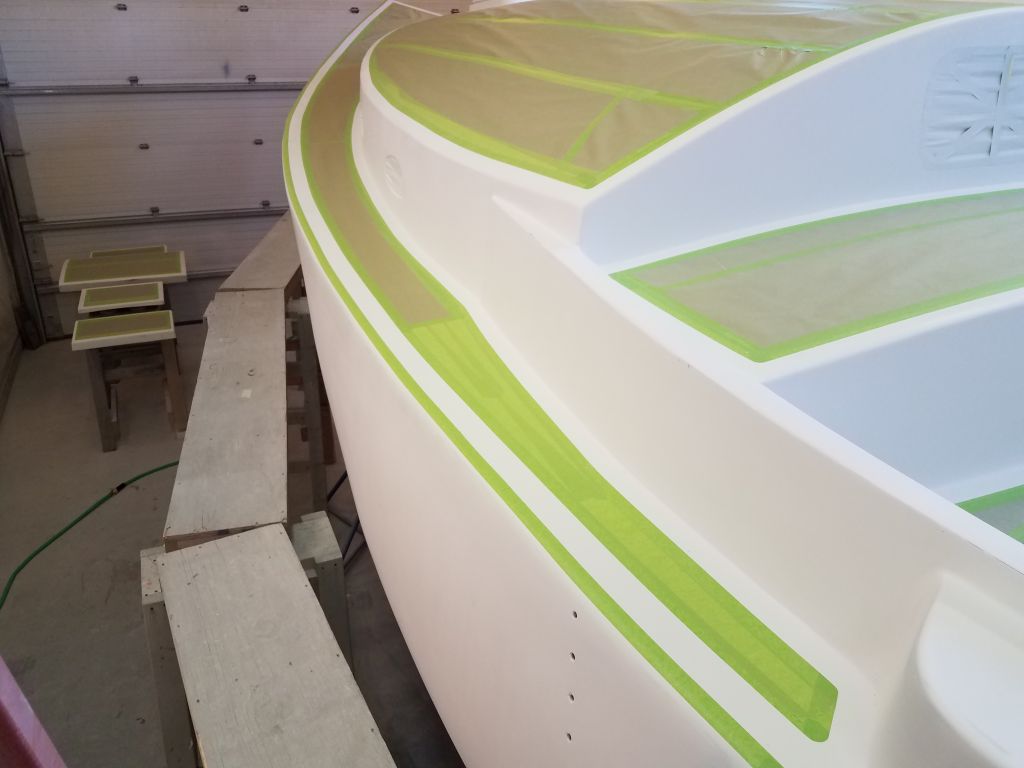
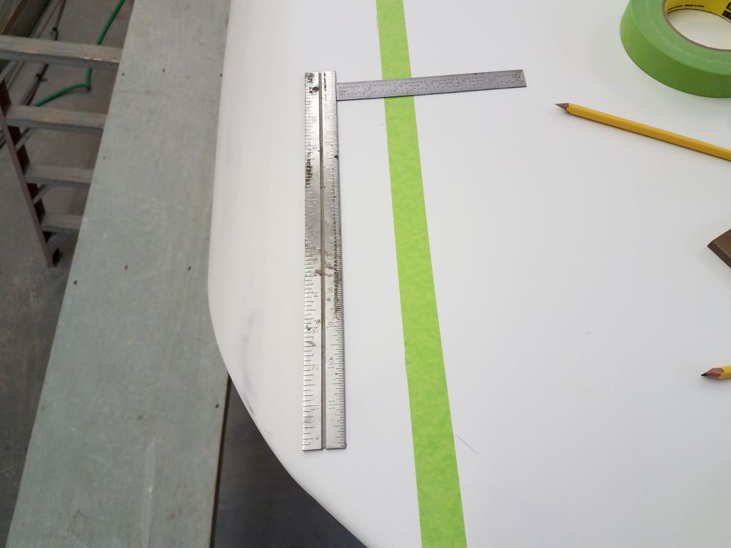
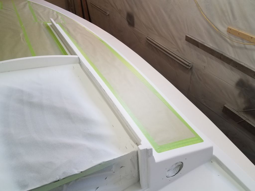
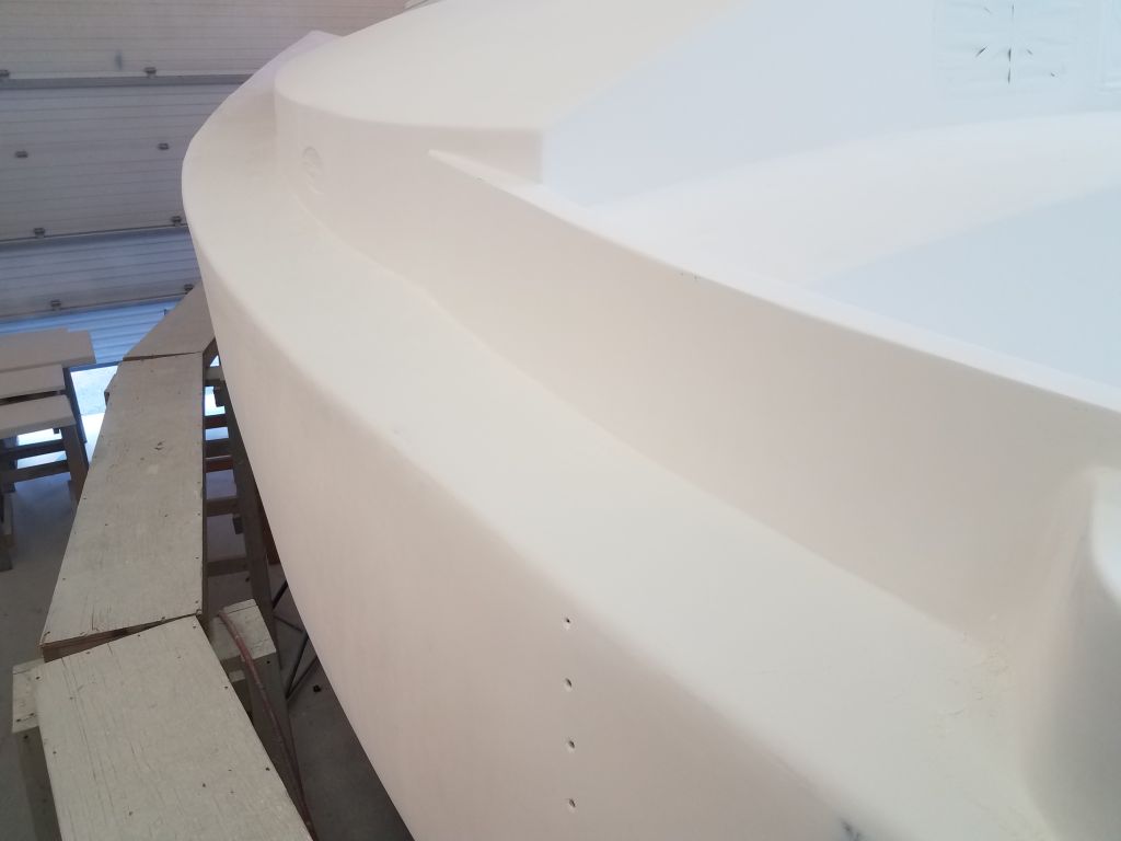
Using the steel rule as an analog for the toerail, I placed it on deck where I thought it should be (i.e. a certain visual distance inboard of the hull/deck roundover), and made a couple reference marks. I made the first mark at the center of the rule’s width (i.e. the center of the toerail), and this was made easy since the steel rule featured a notch down the center. This mark would represent the inside edge of the tape line I’d install to cover the hull against overspray and demark the hull and deck paint.
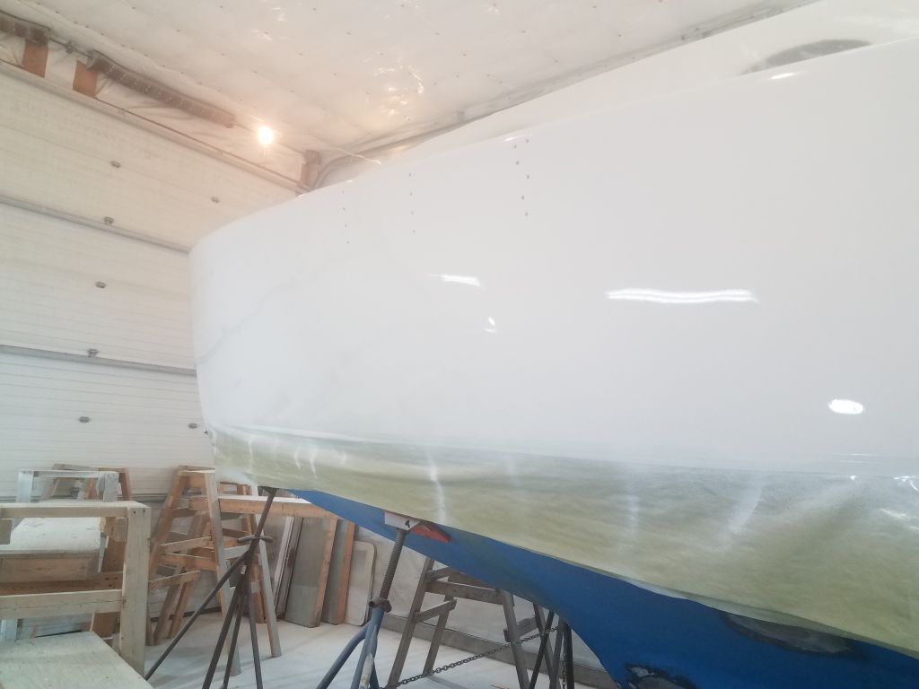
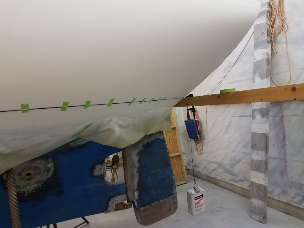
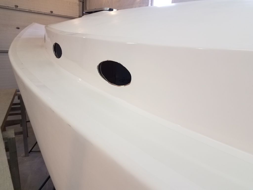
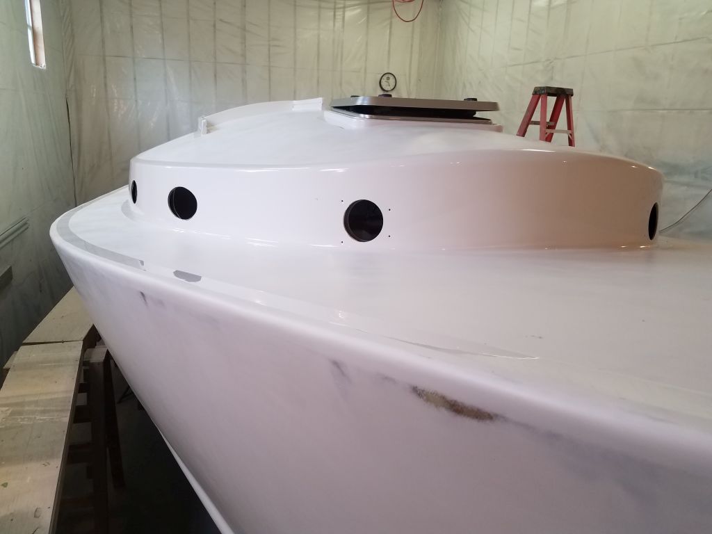
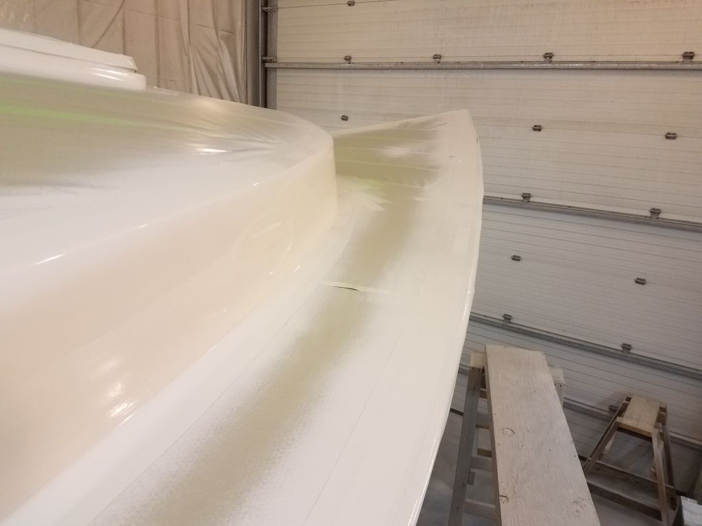
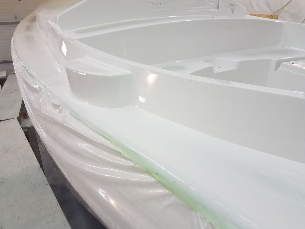
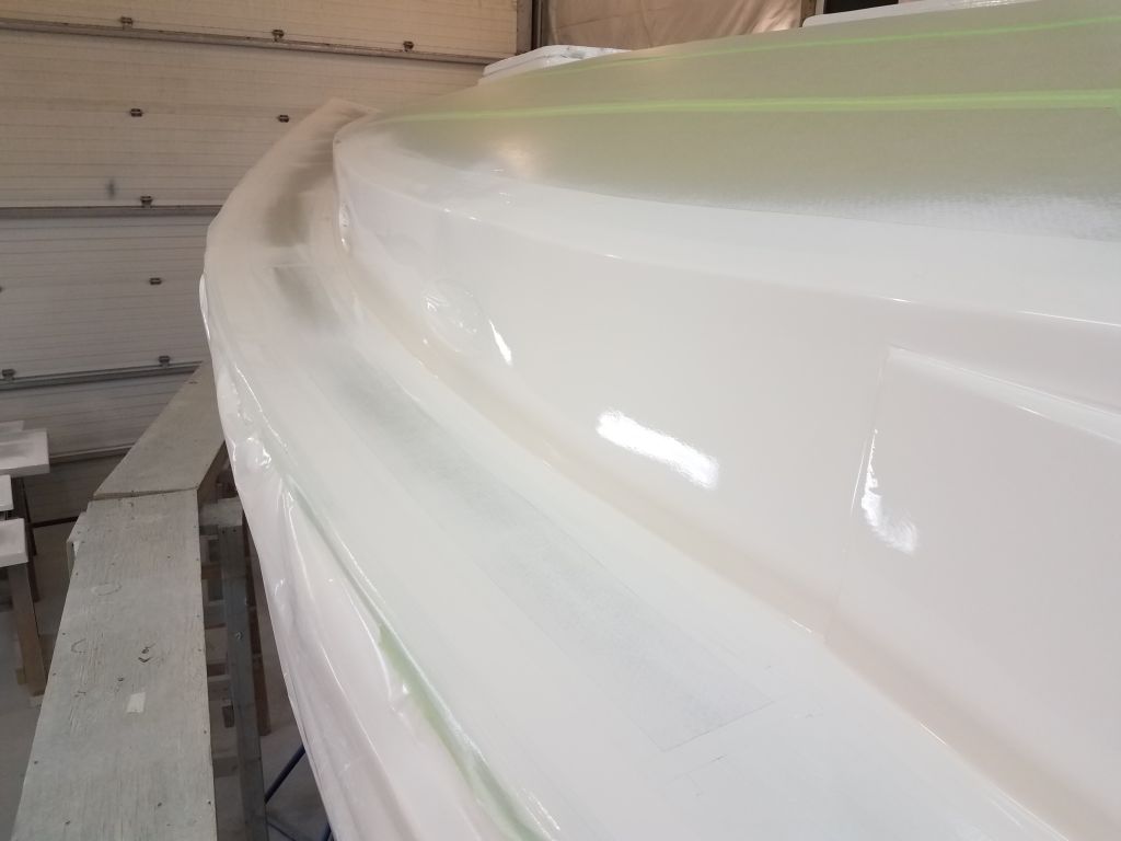
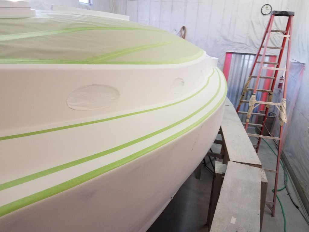
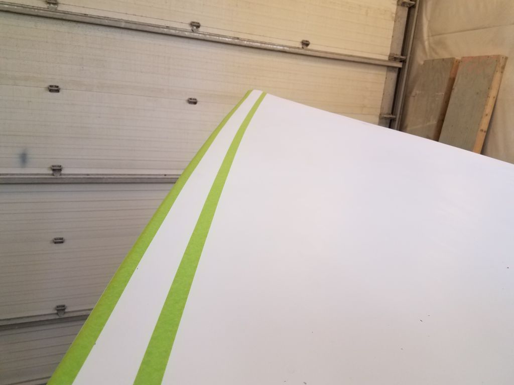
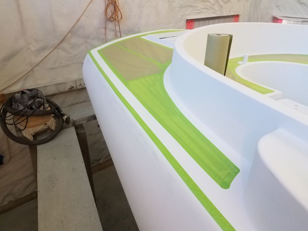
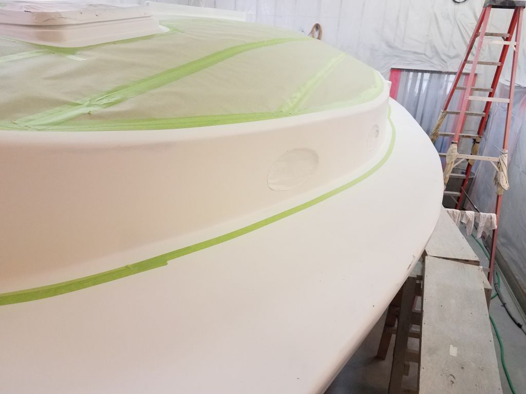
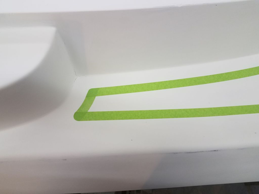
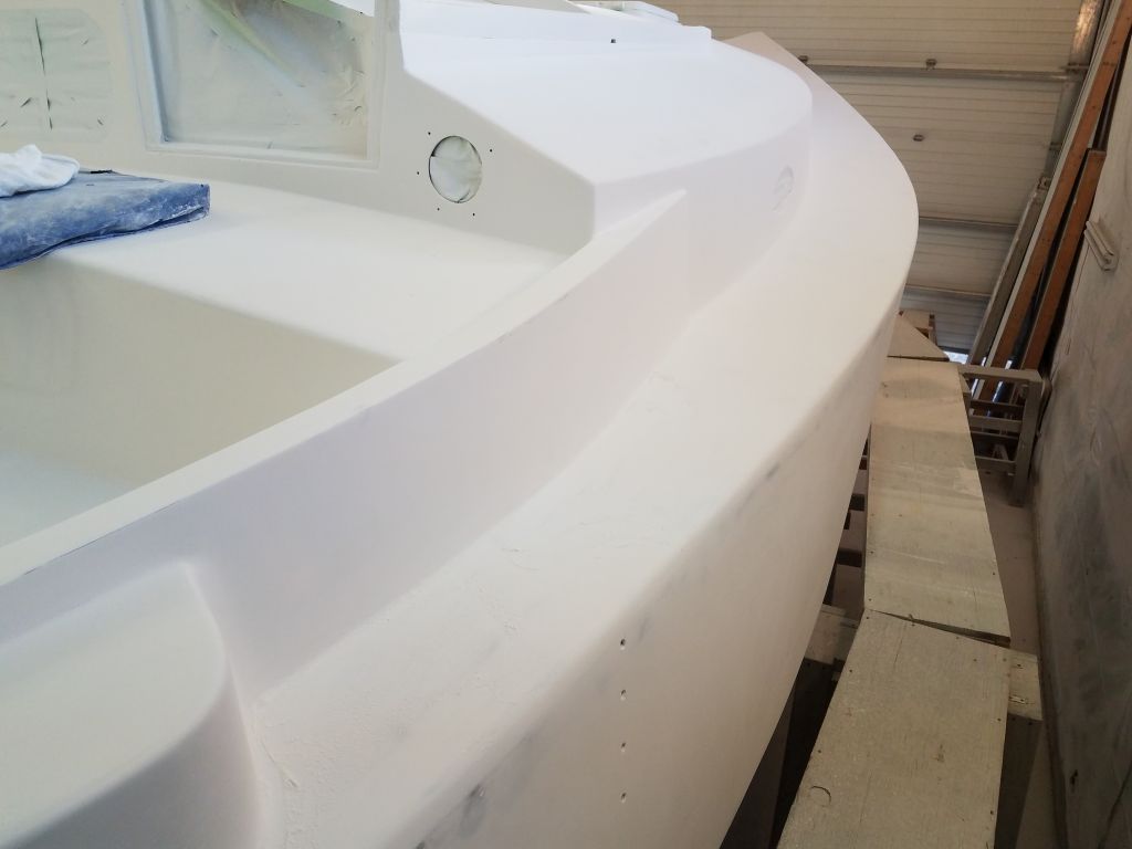
Using another, smaller steel rule, I made the second mark 1-1/2″ in from the inside edge of the “toerail”, and this mark defined the line against which I’d mask for the deck edge border, or channel. I repeated this marking process ever few inches along the four-or five-foot length of the hull where I was working, from the winch island aft to the transom. Then, I masked to the line, fairing the tape by eye as needed. This ultimately created the clean, fair line that I wanted and needed inboard of the eventual toerail.
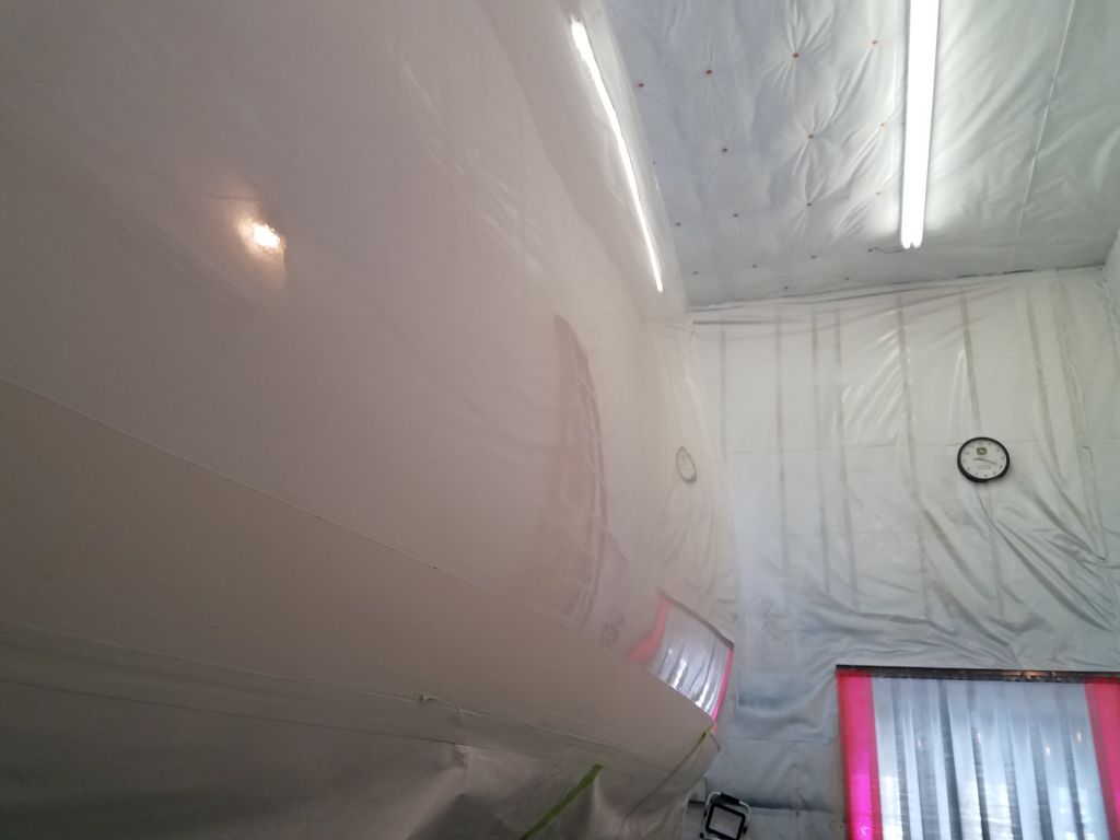
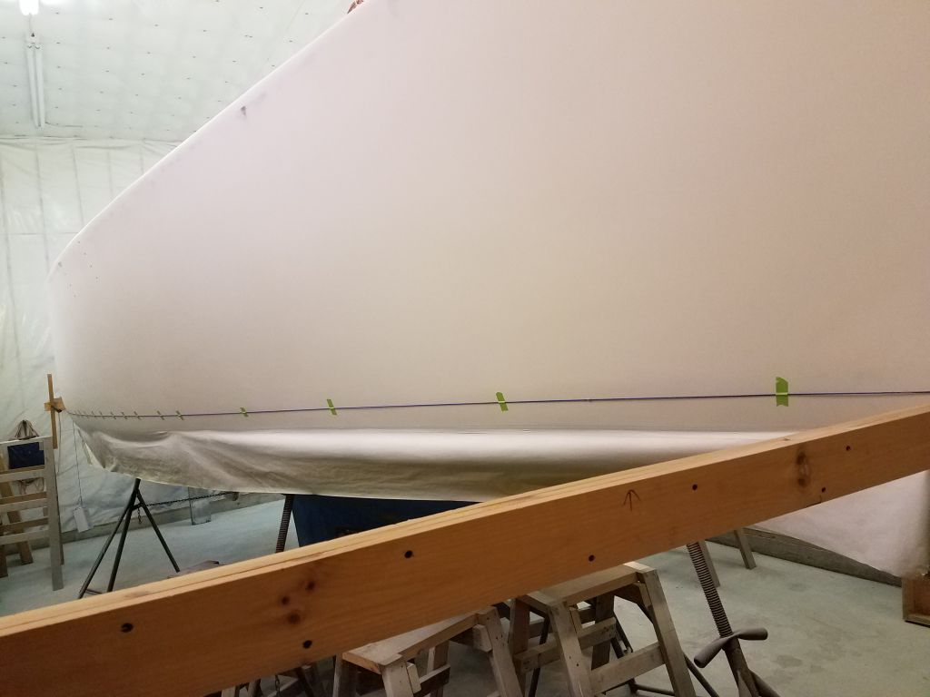
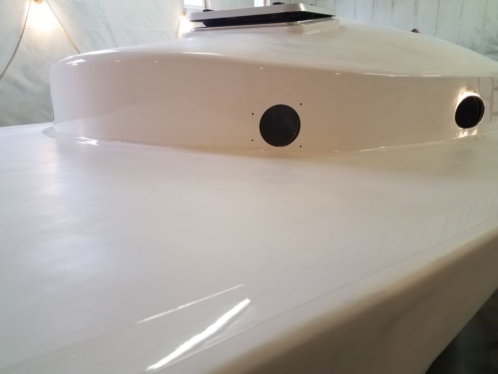
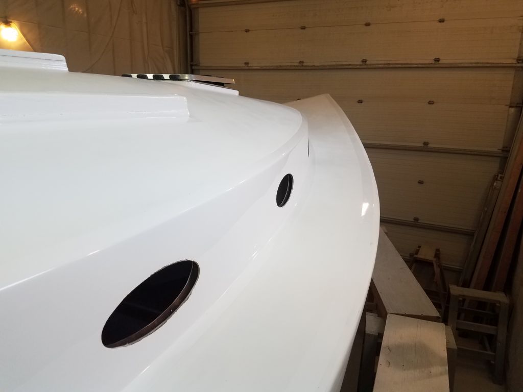
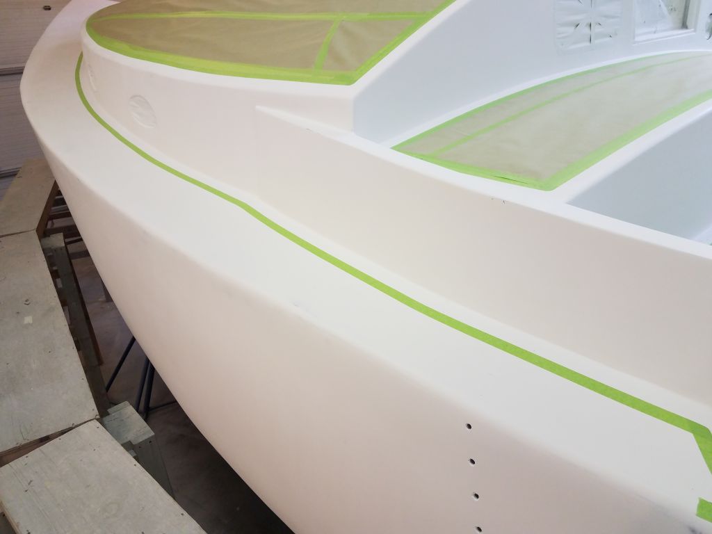
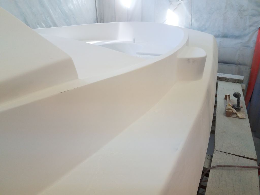
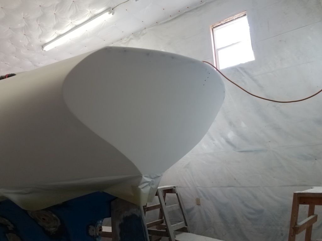
Next, I could mask to the outboard marks, leaving the tape on the hull side of these marks.
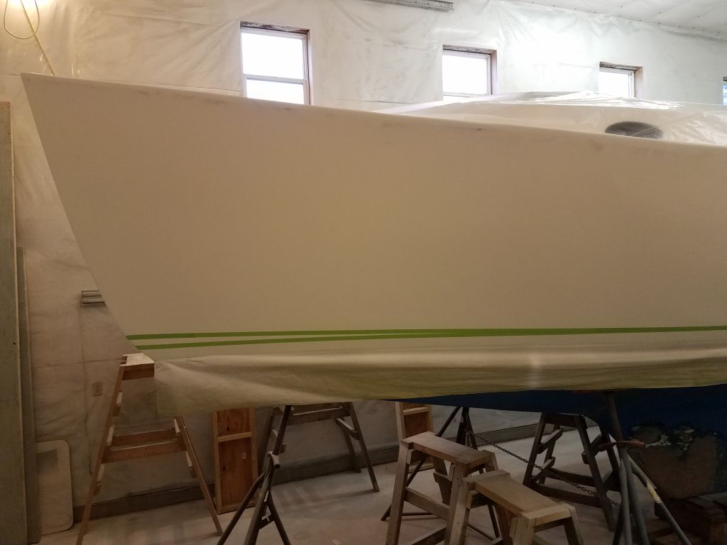
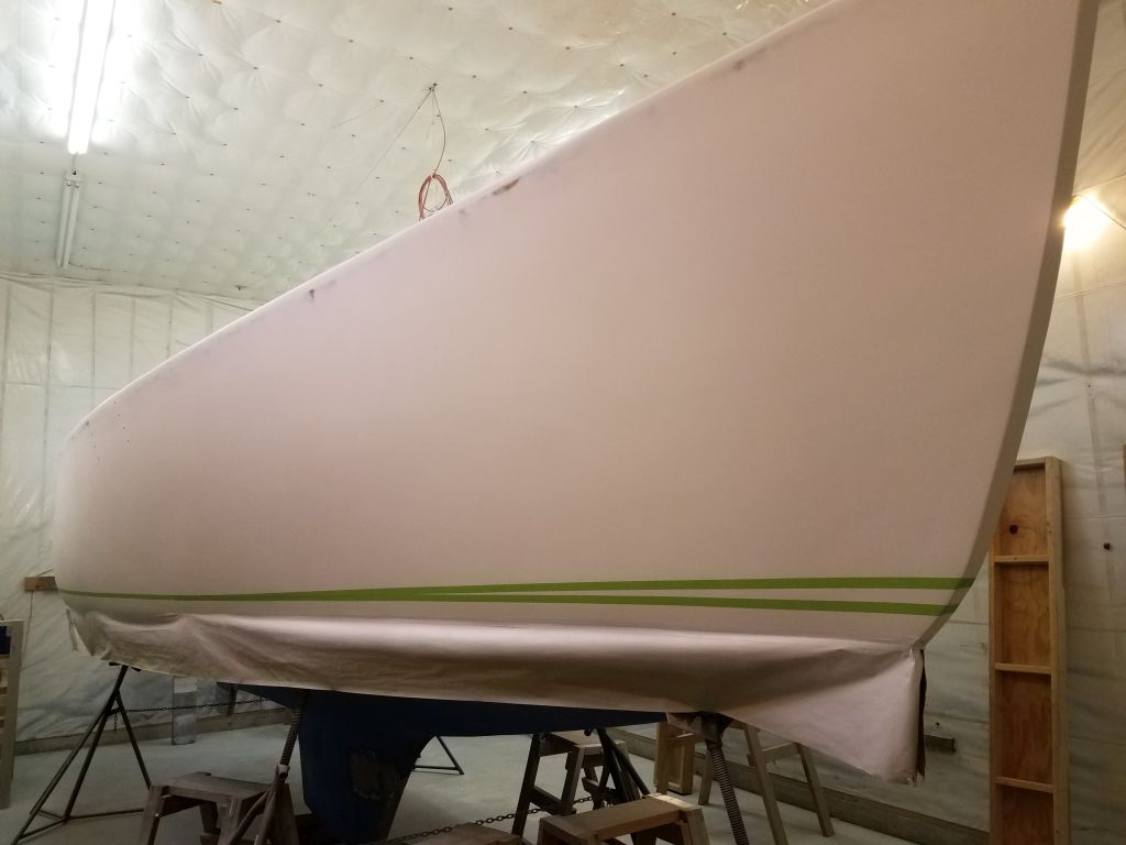
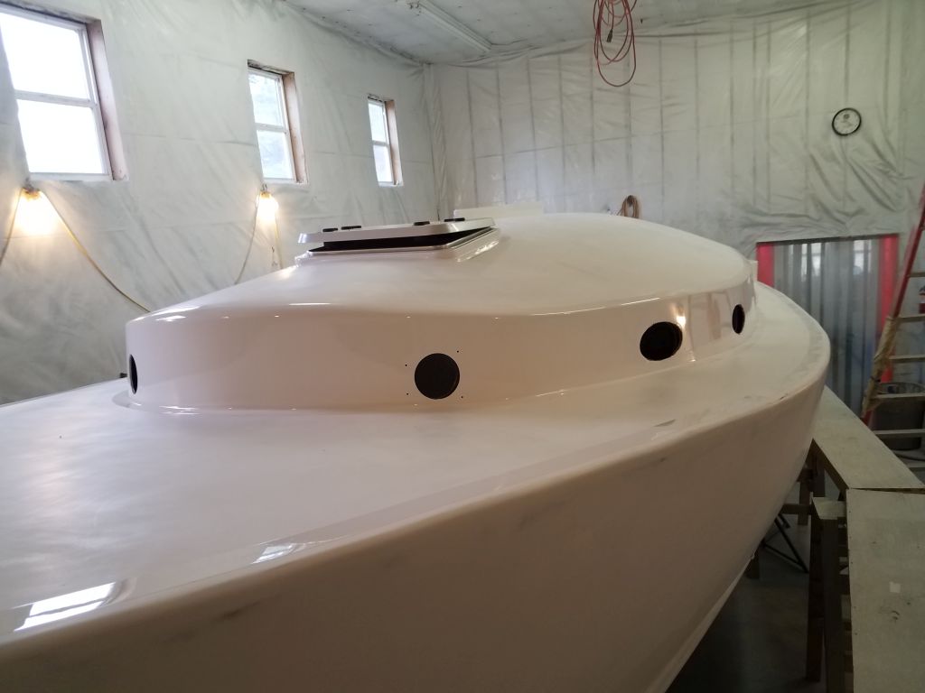
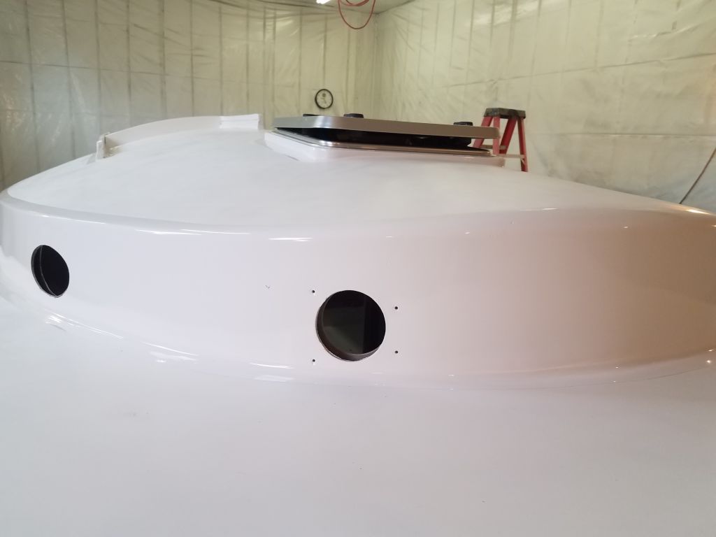
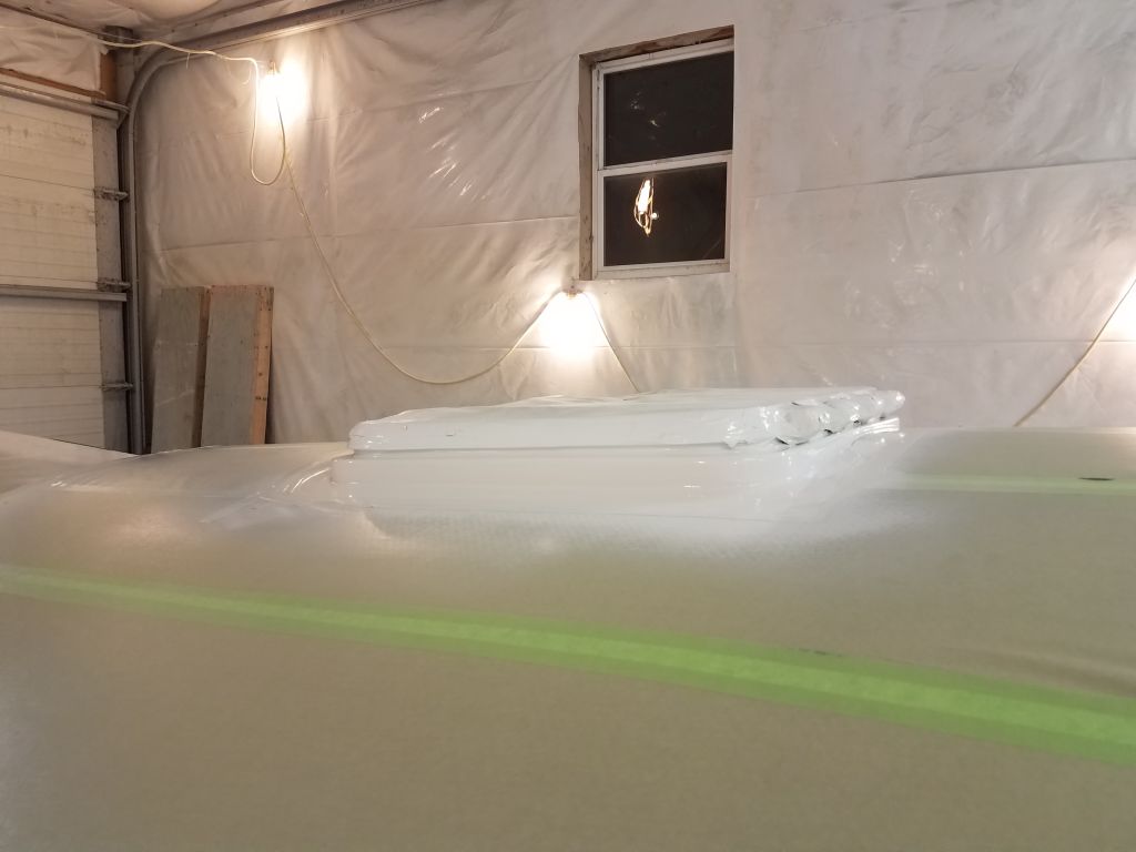
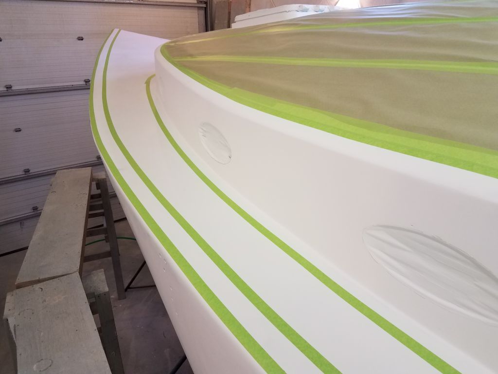
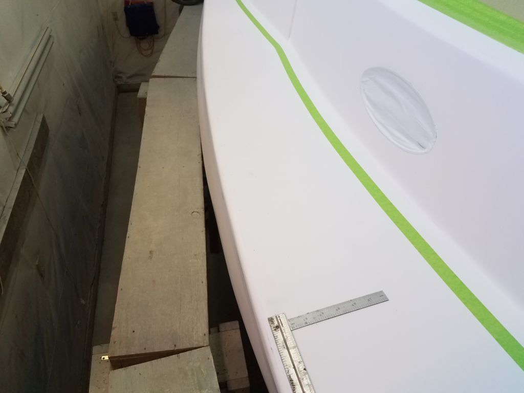
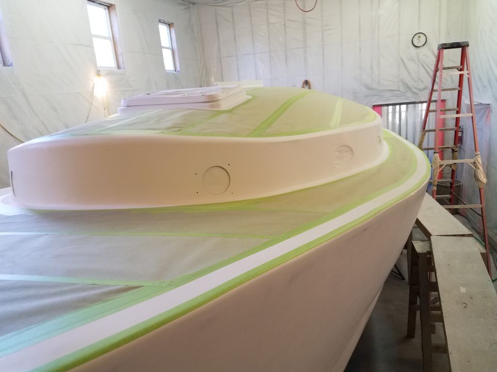
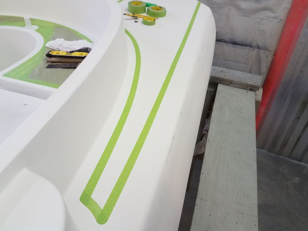
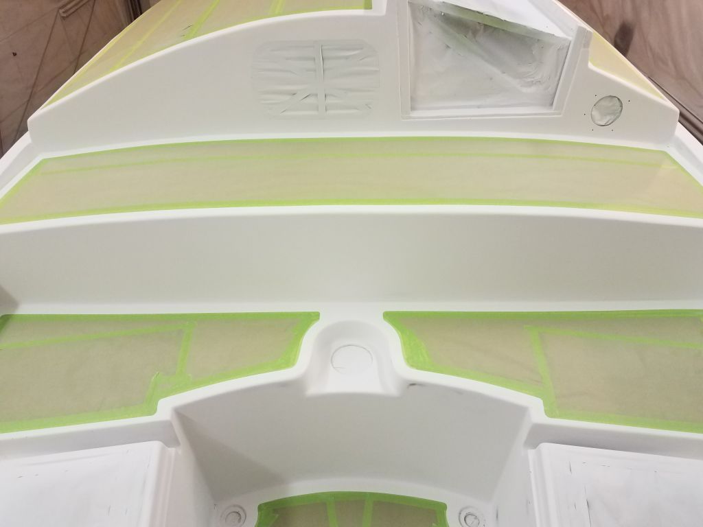
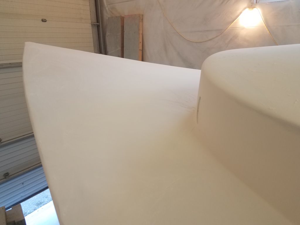
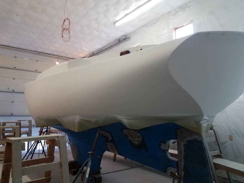
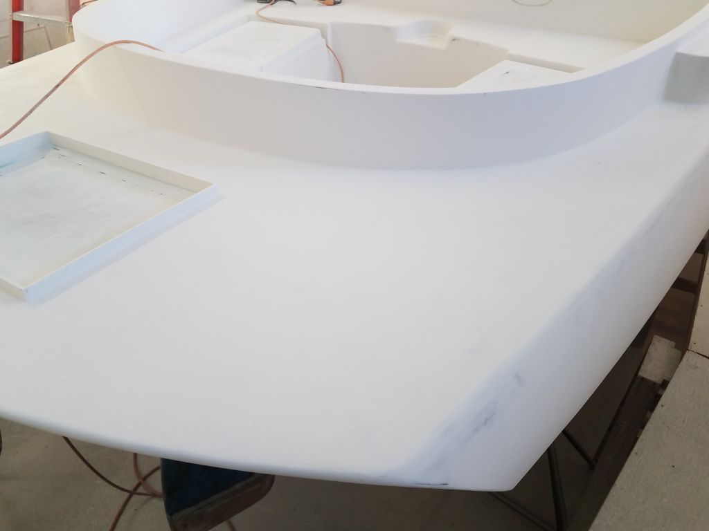
Flush with success, I repeated the marking and masking process across the curvy transom, validating the methodology in the process.
Now that I had the basic method worked out, marking the remainder of the deck edges would go more quickly, and I looked forward to finishing that up next time, but for now I had to head out for appointments, and boat-related and unrelated errands.
Total time billed on this job today: 5 hours
0600 Weather Observation: 45°, cloudy. Forecast for the day: Clouds and showers, 52°