Thursday
The mast painting remained my main focus, but since there was little prep required before I could apply the gloss topcoat, I decided to use the morning to take care of some smaller jobs before continuing on the mast.
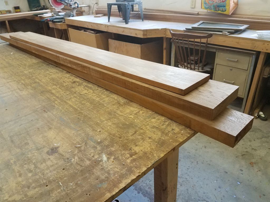
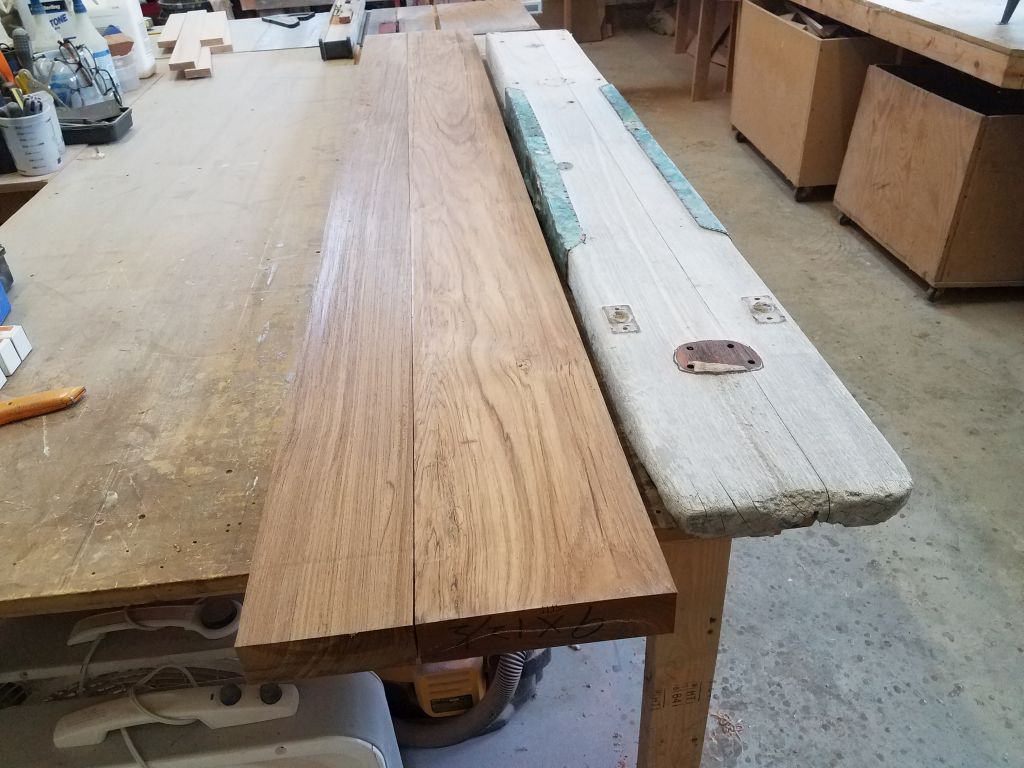
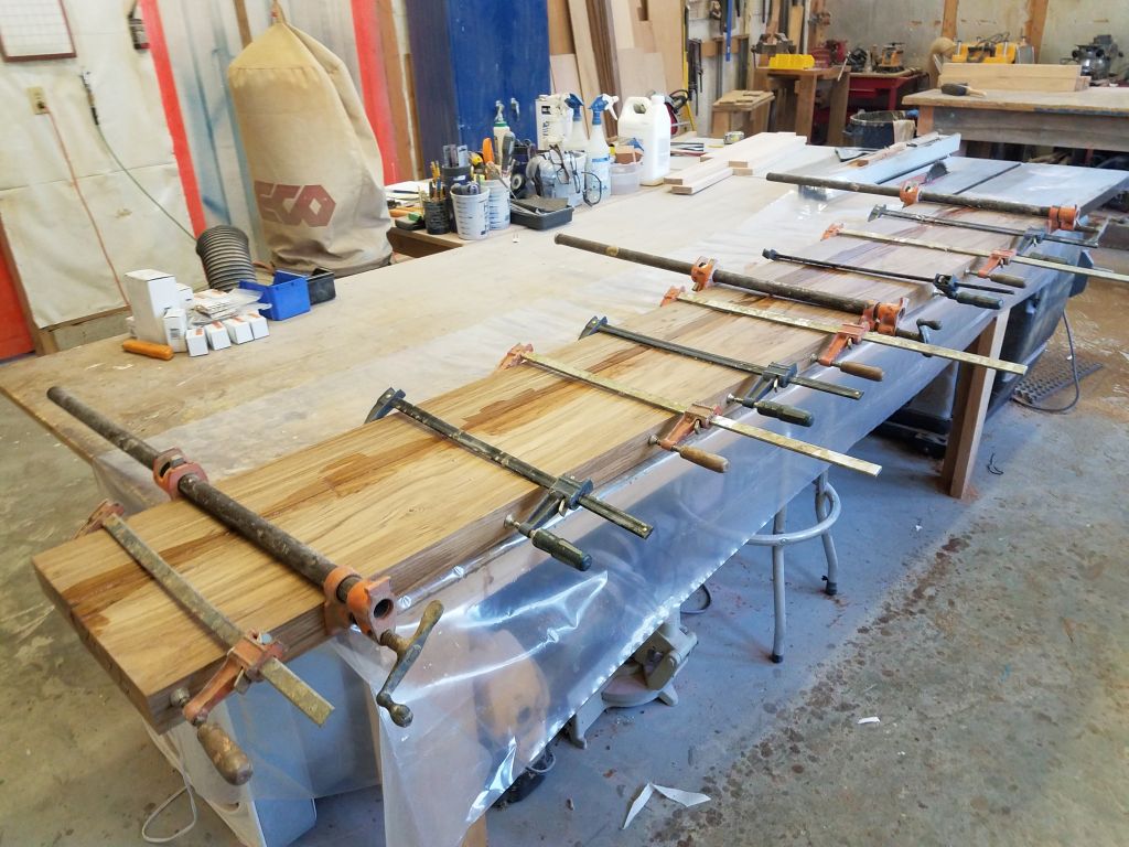
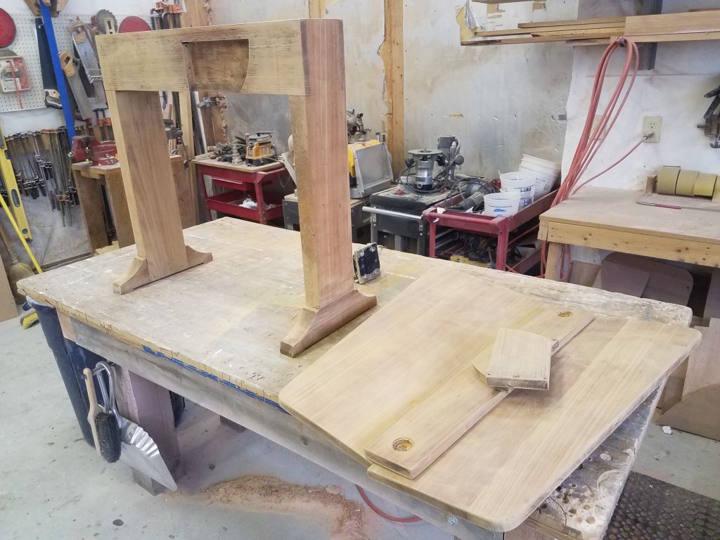
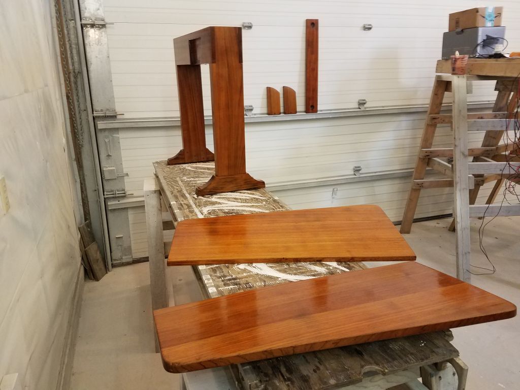
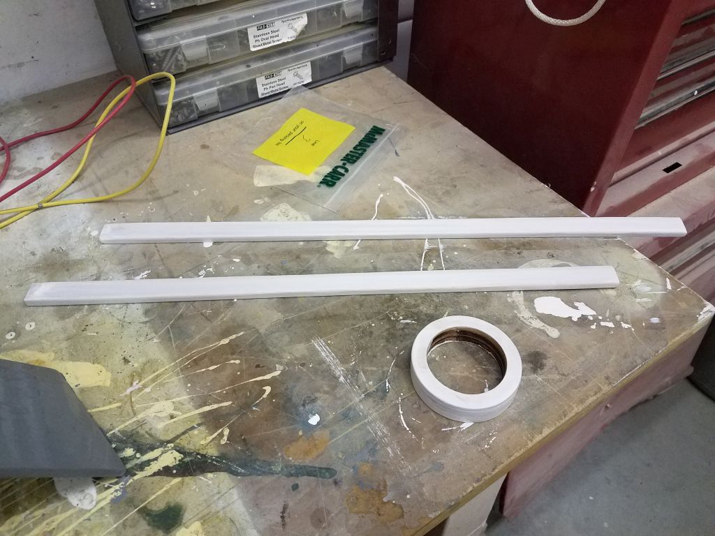
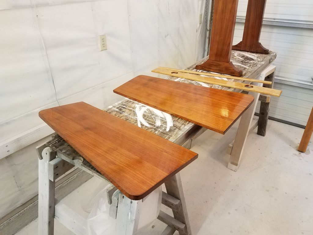
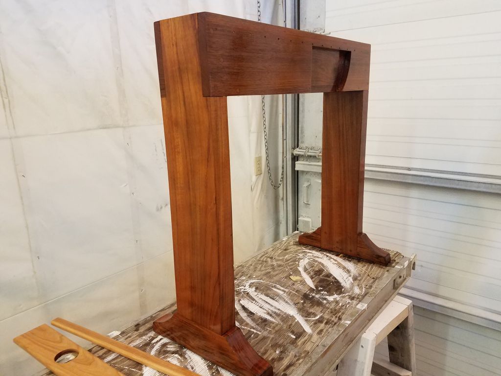
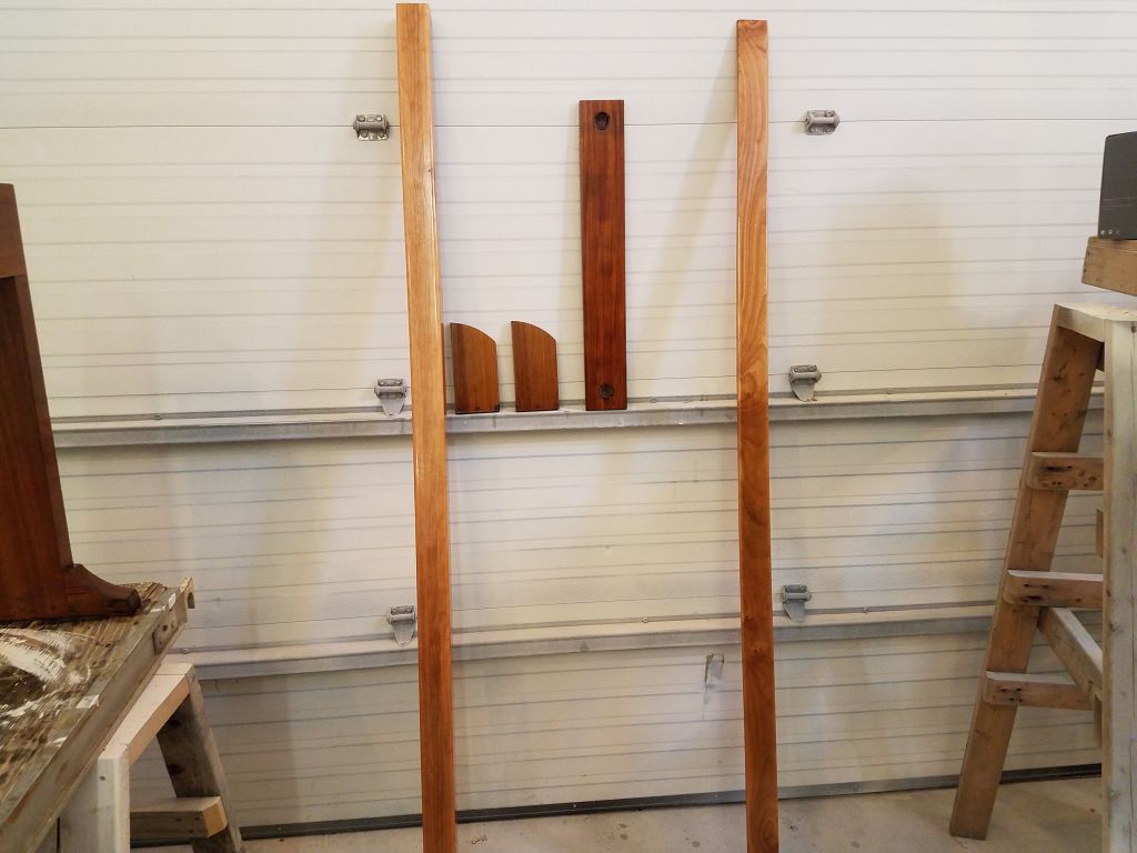
I wanted to keep the varnish work going on the cabin table and various trim parts that I’d started before the holidays, so to get going I lightly sanded everything and, after cleanup, applied a second coat of gloss varnish to all surfaces.
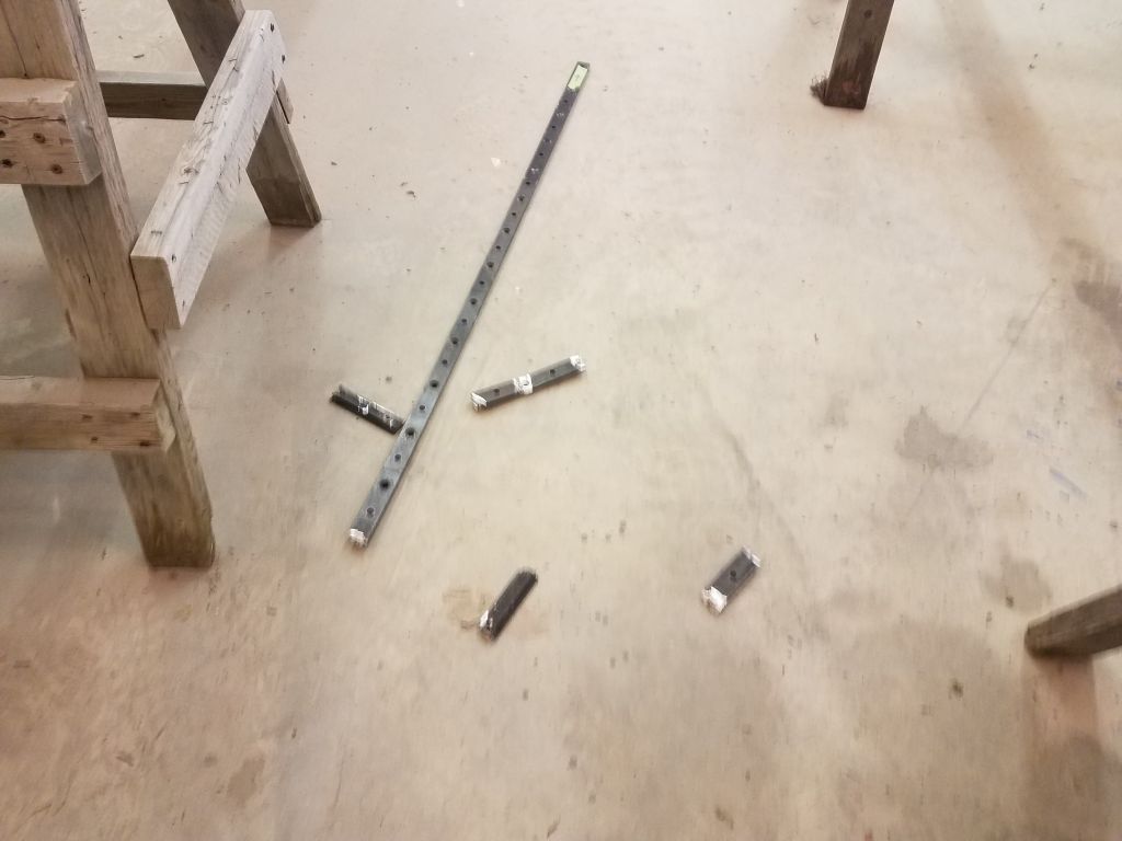
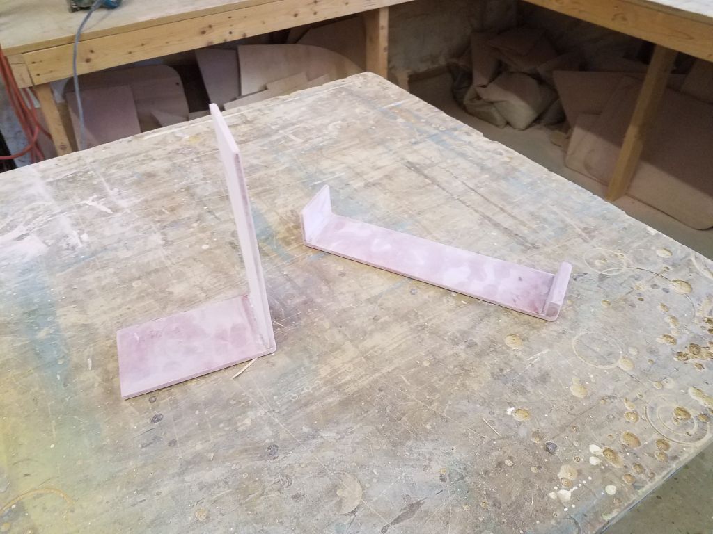
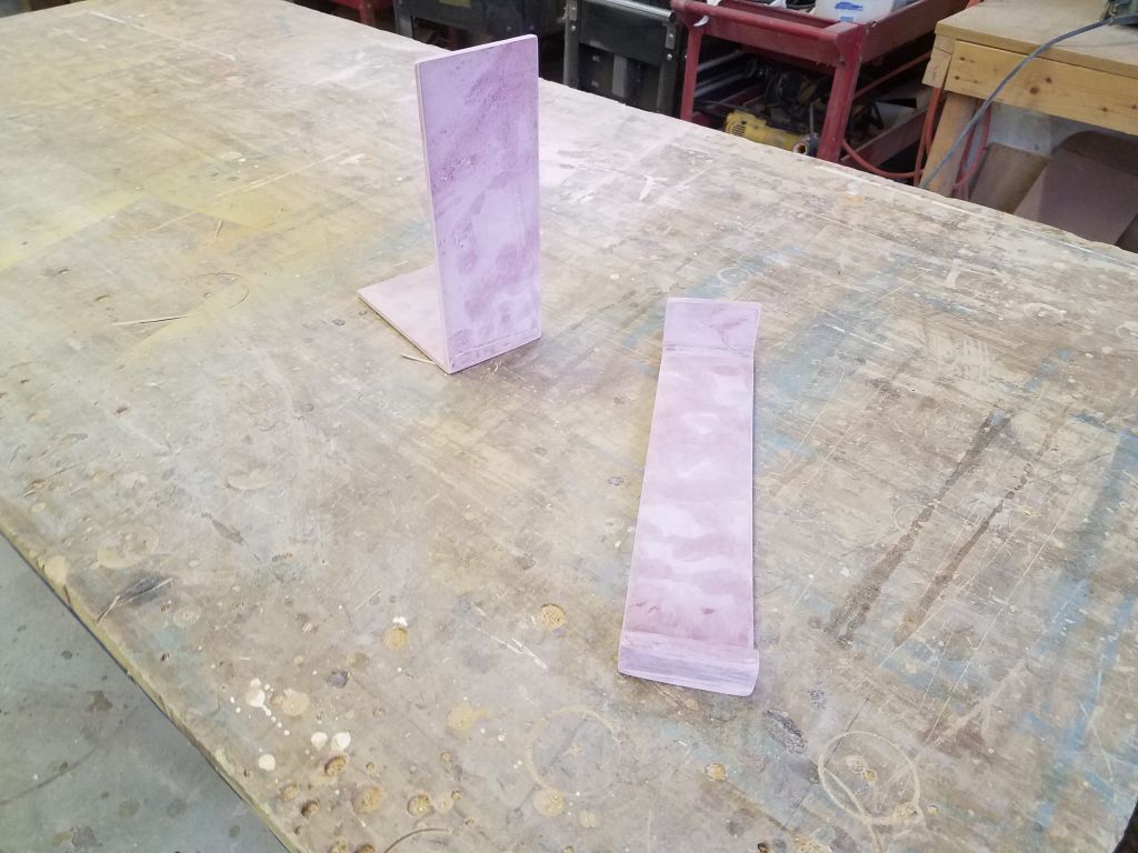
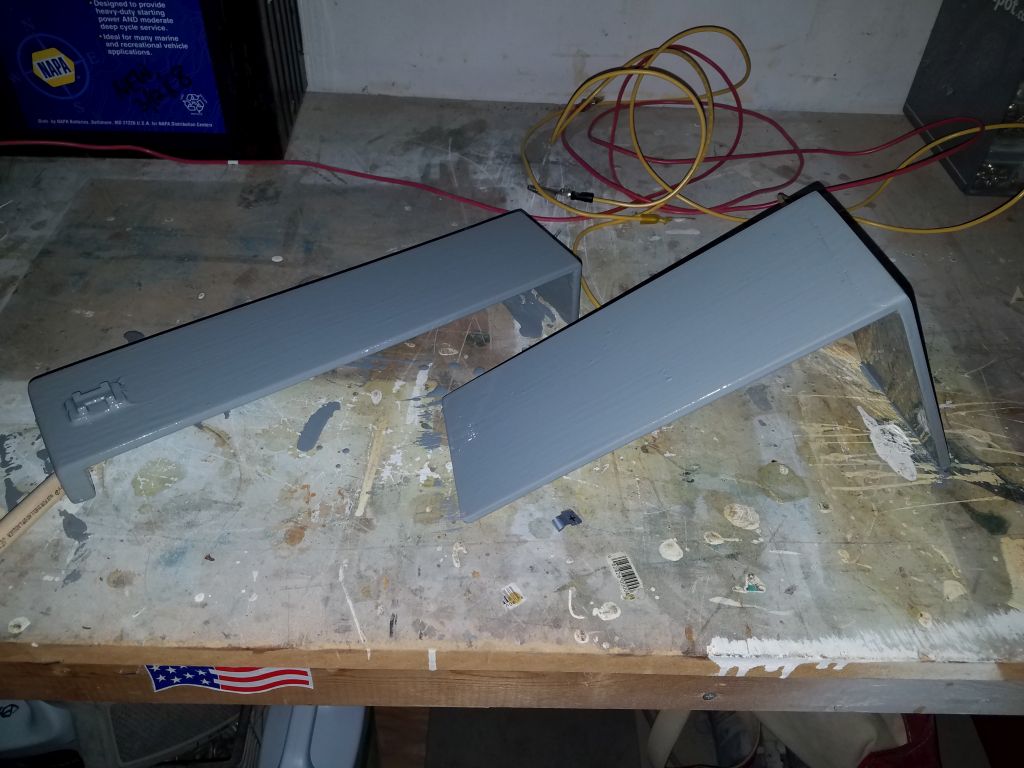
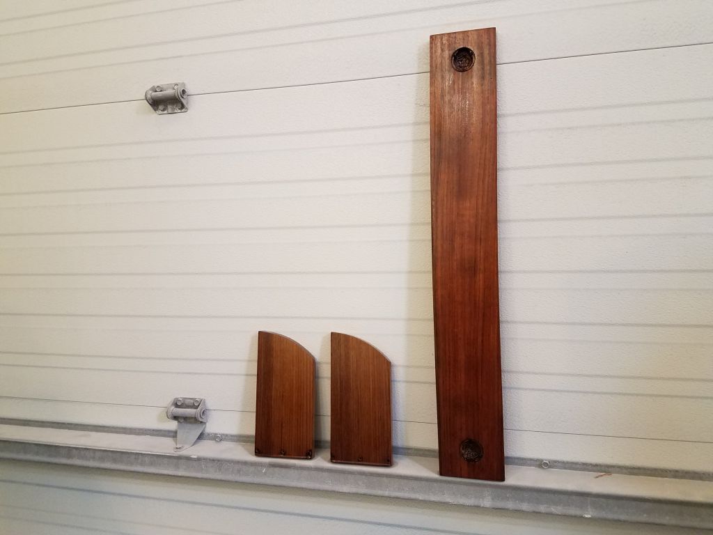
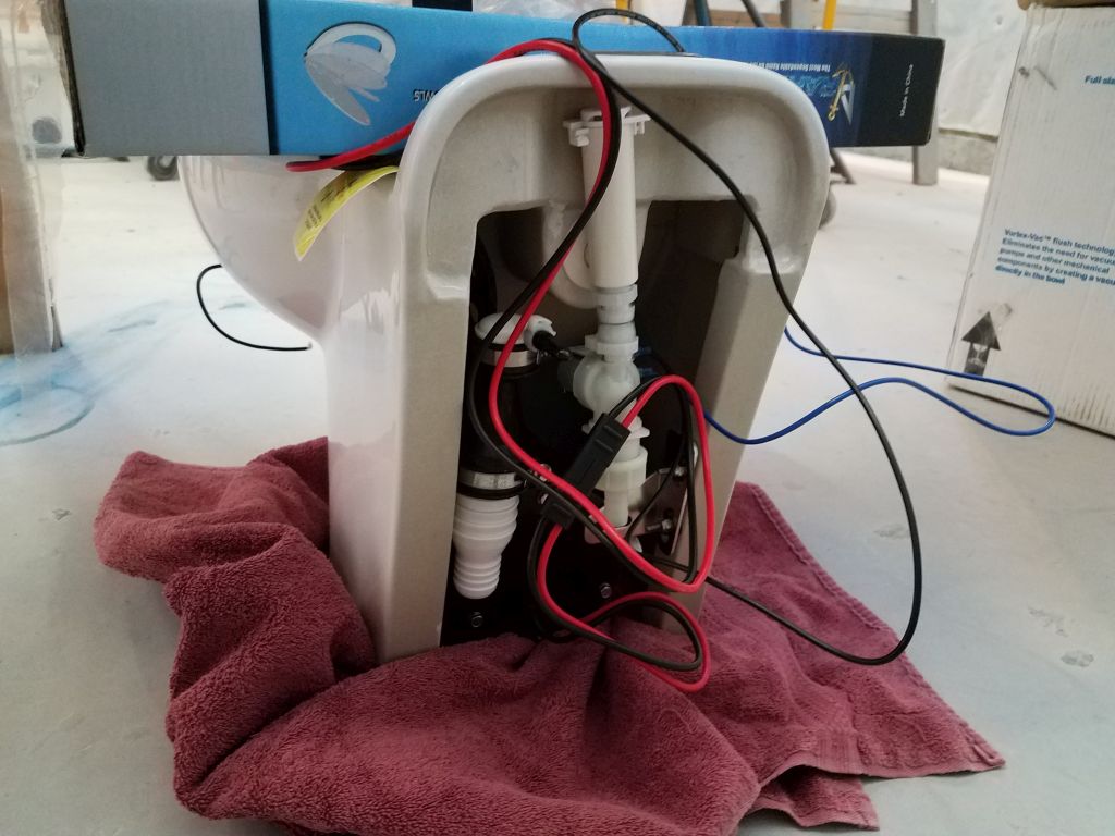
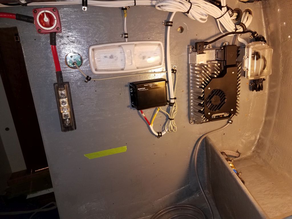
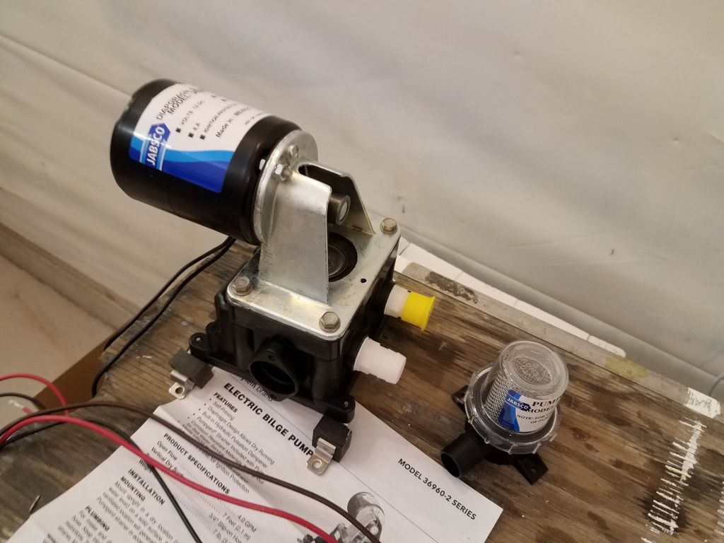
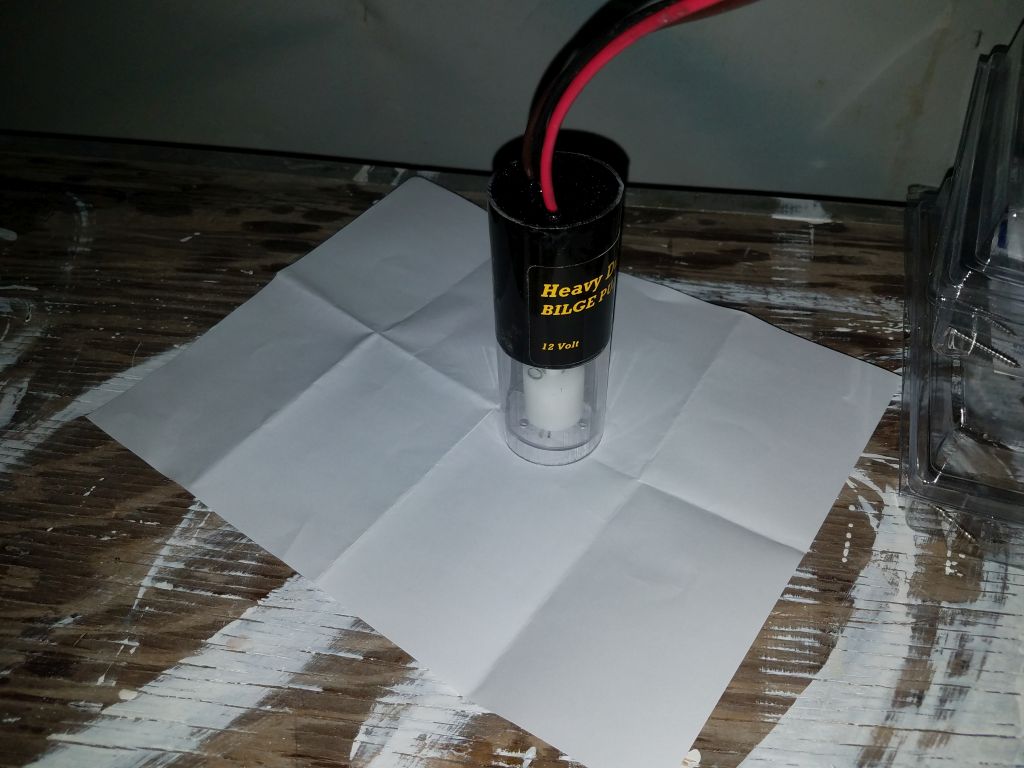
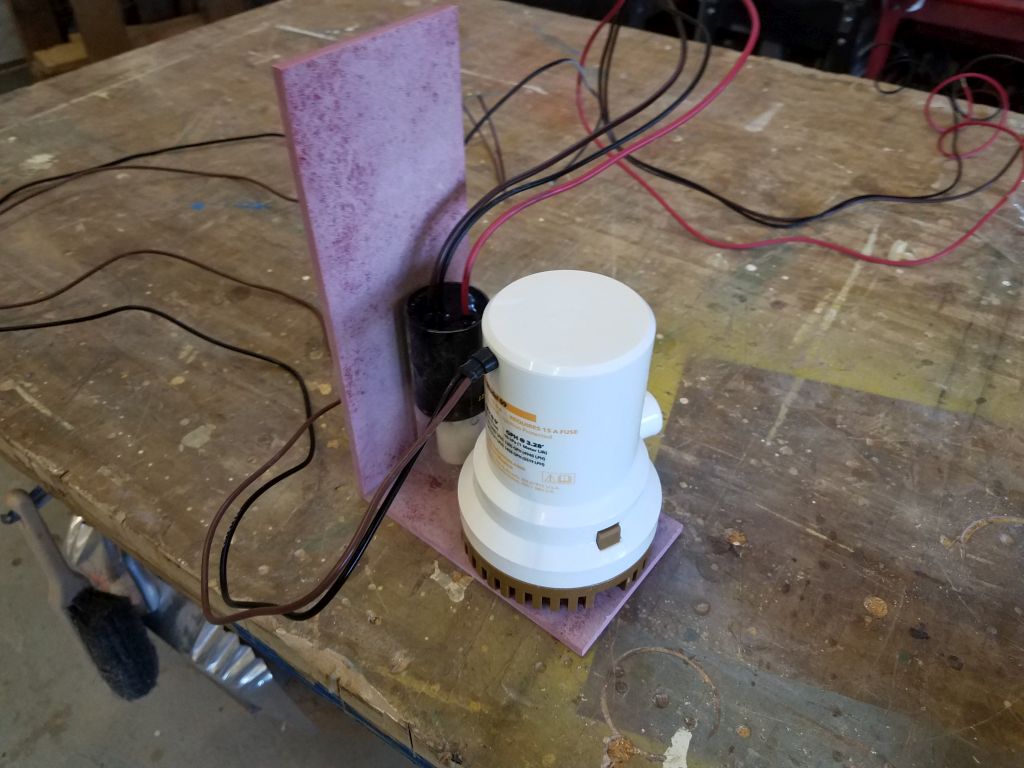
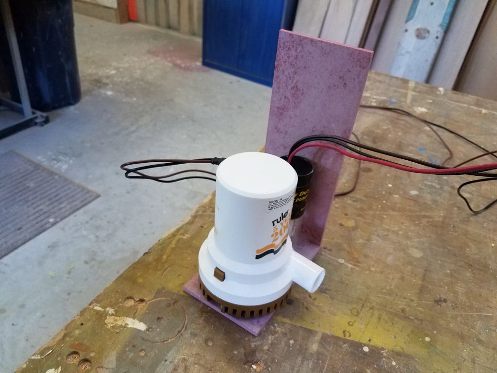
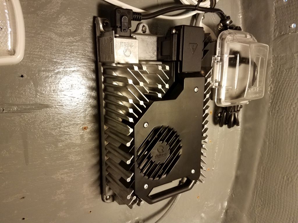
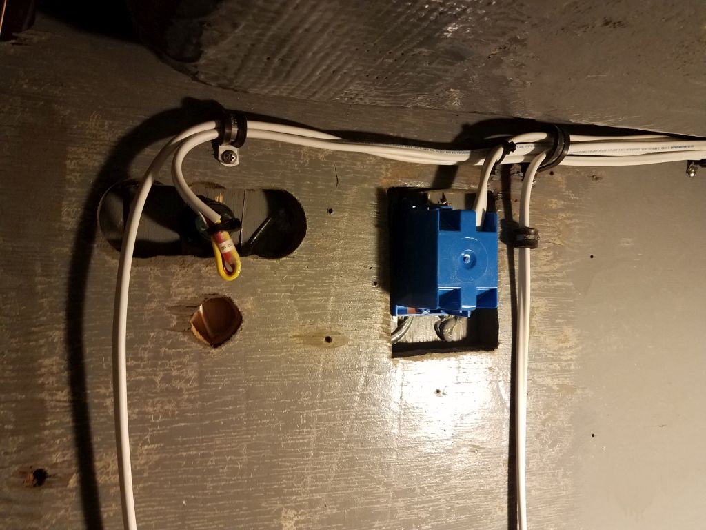
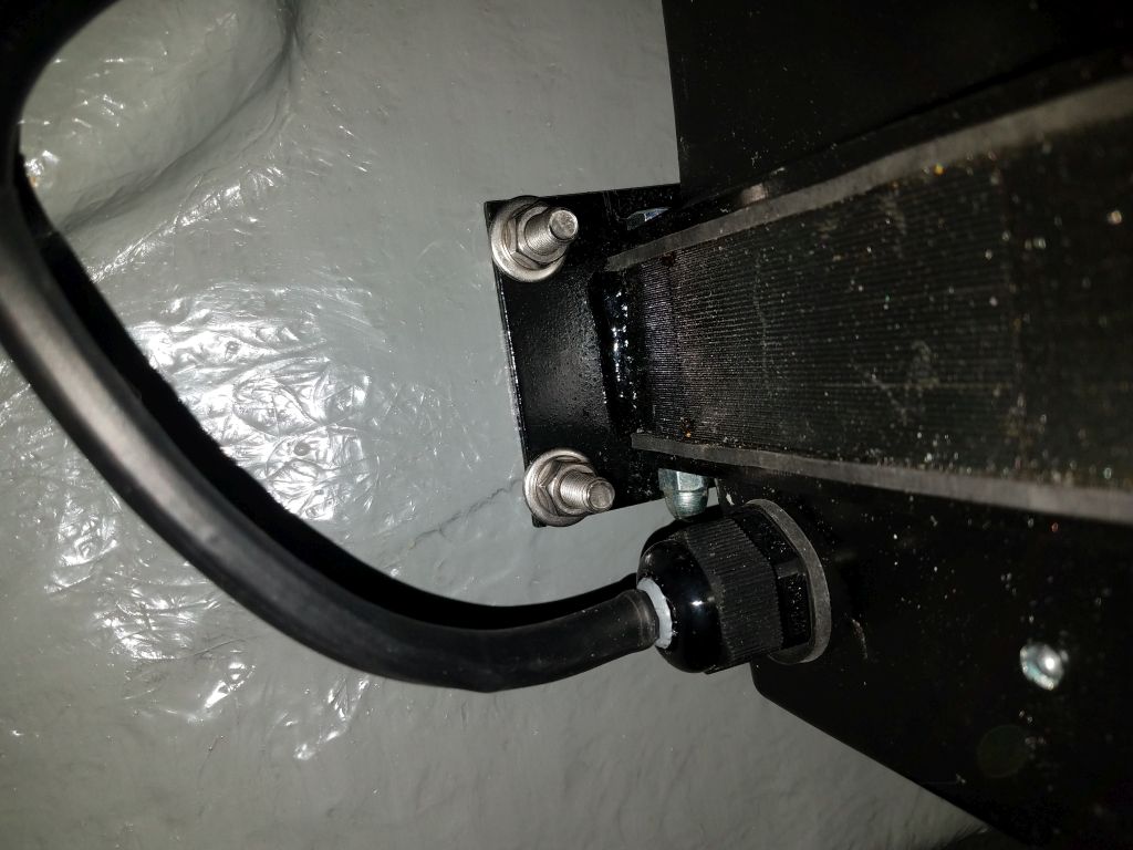
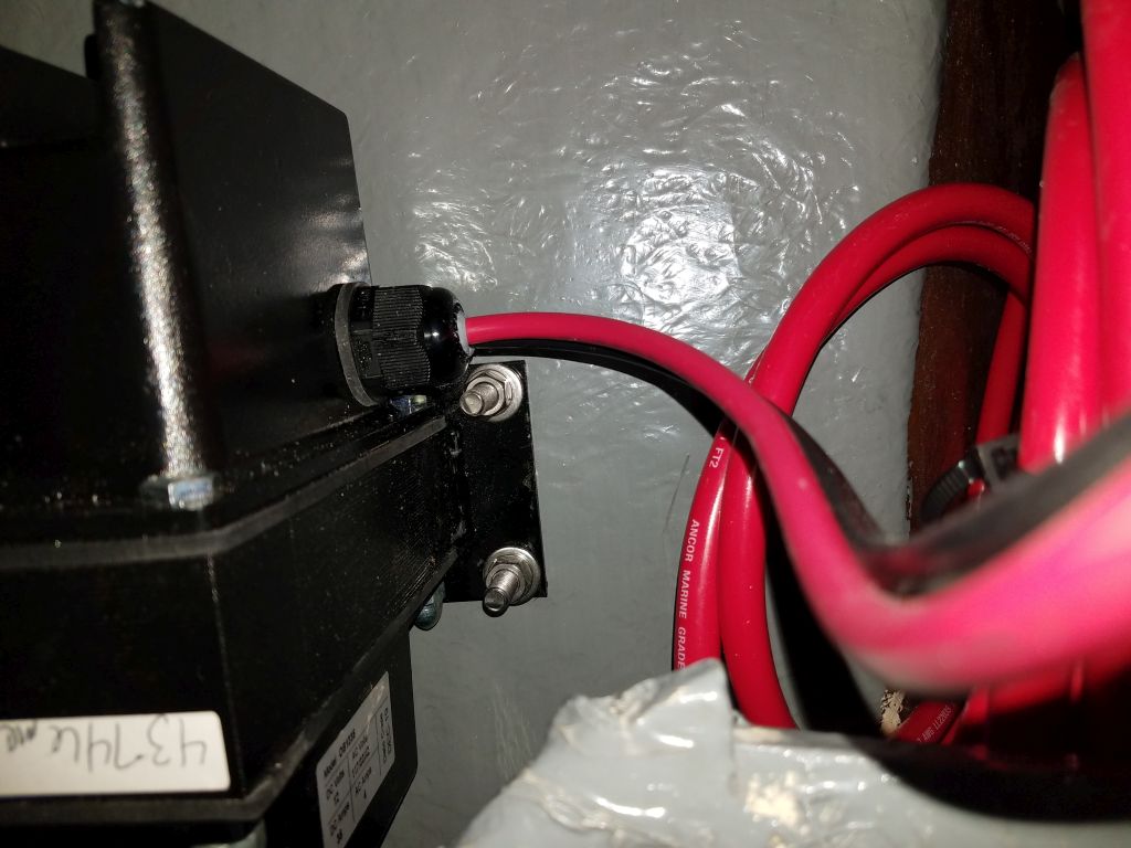
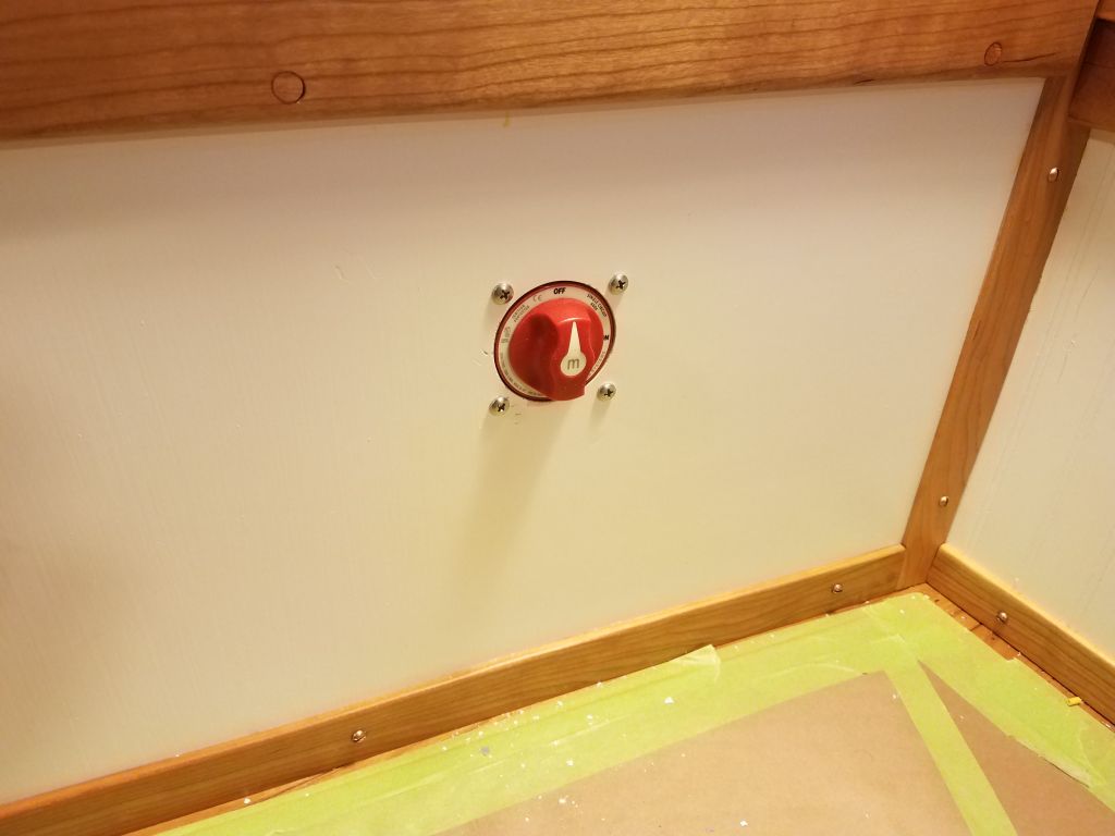
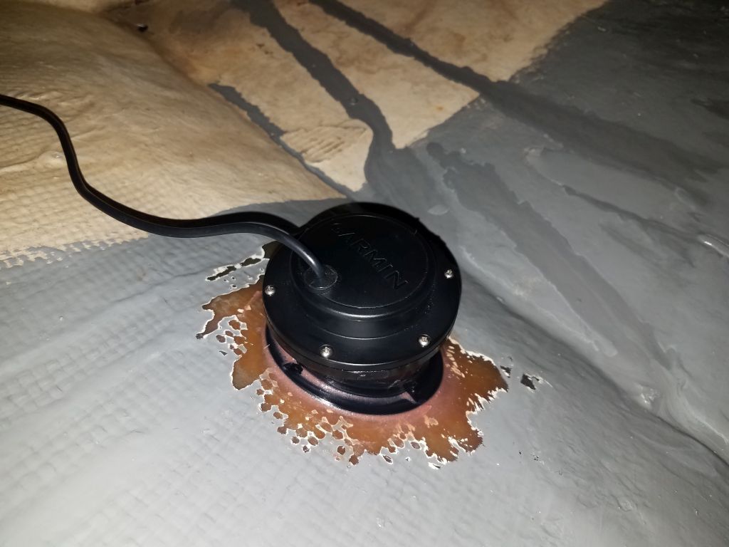
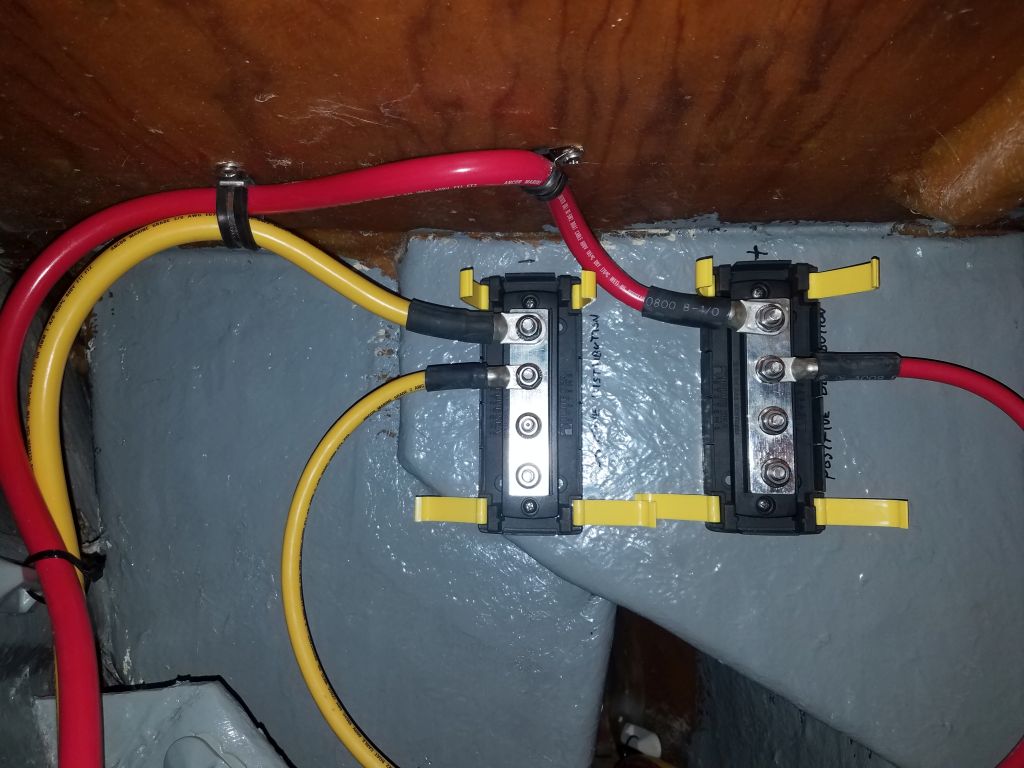
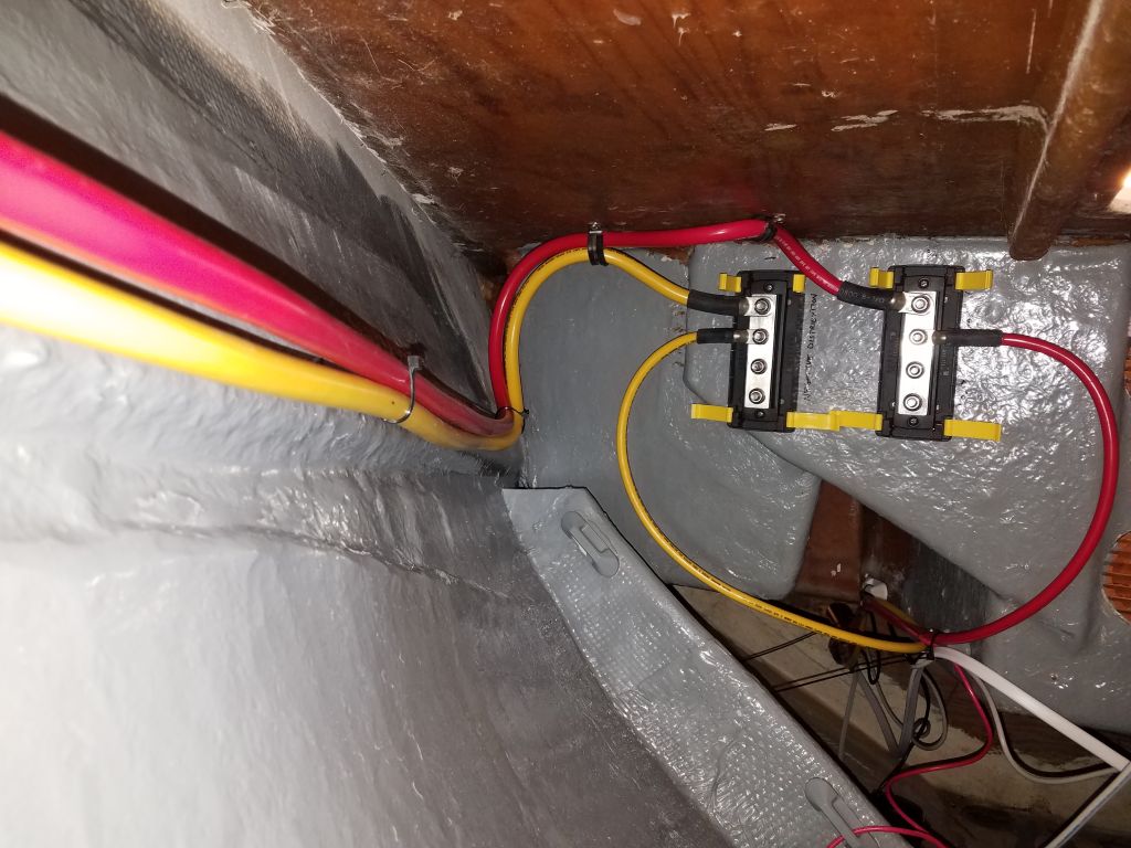
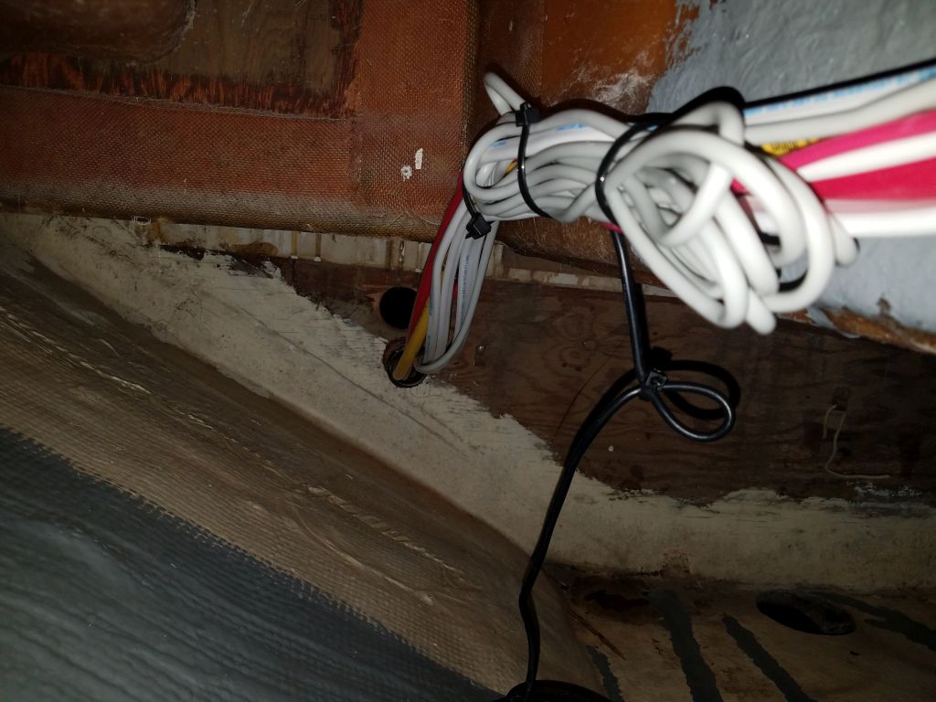
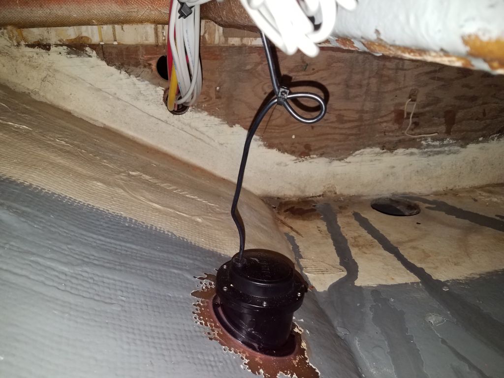
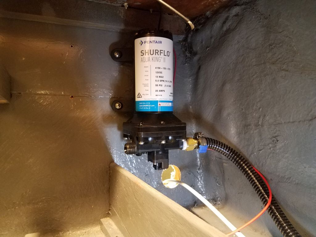
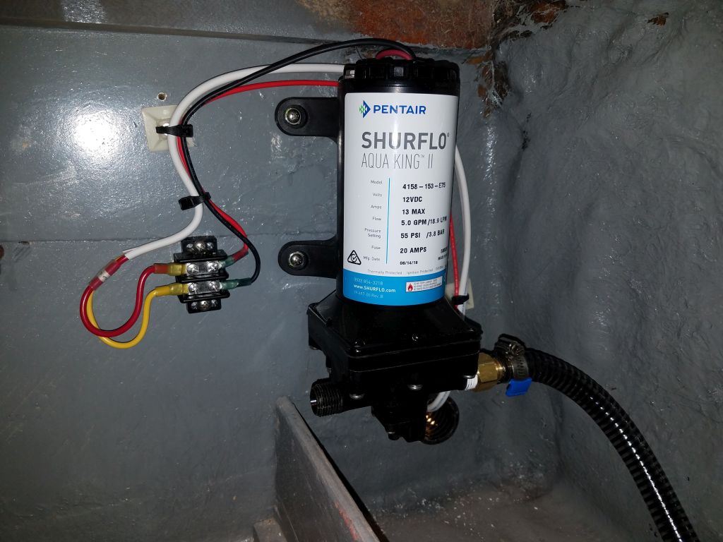
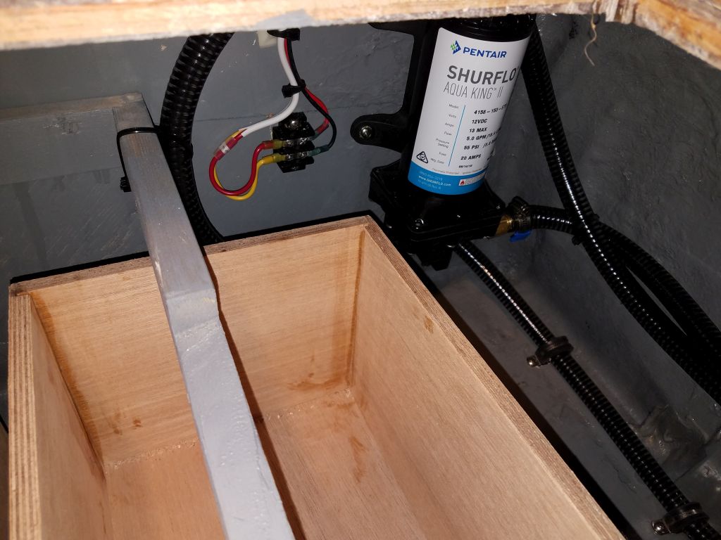
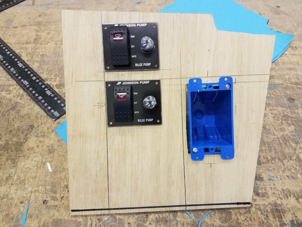
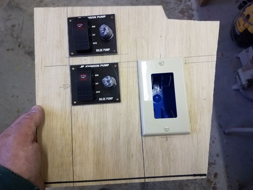
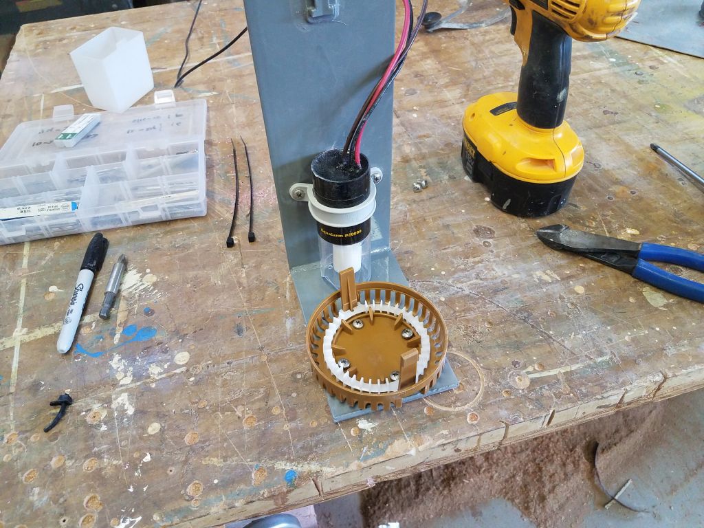
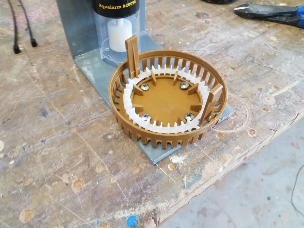
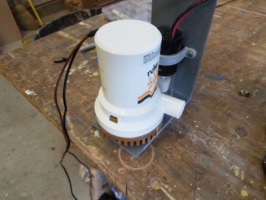
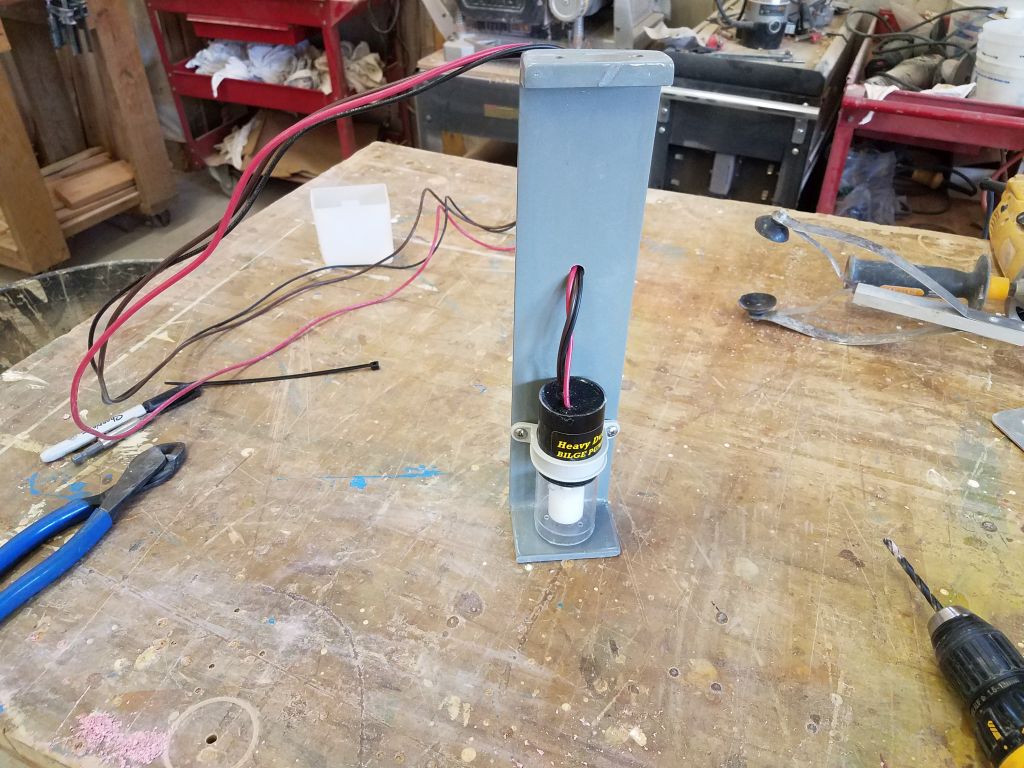
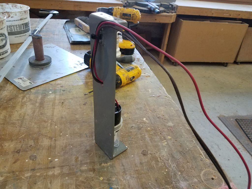
On my new bracket, I installed one of the automatic switches, along with the base for the centrifugal bilge pump, using short screws tapped into the fiberglass to avoid penetration through the bracket itself. I aligned the bilge pump base so that the outlet of the pump would face the desired direction once the bracket was installed.
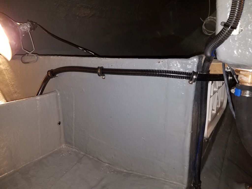
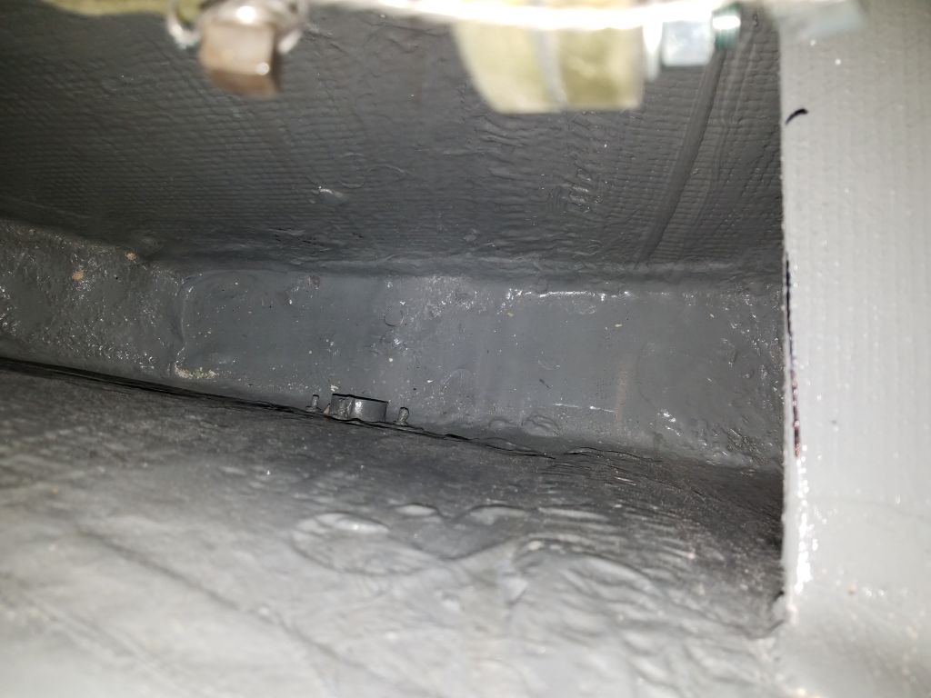
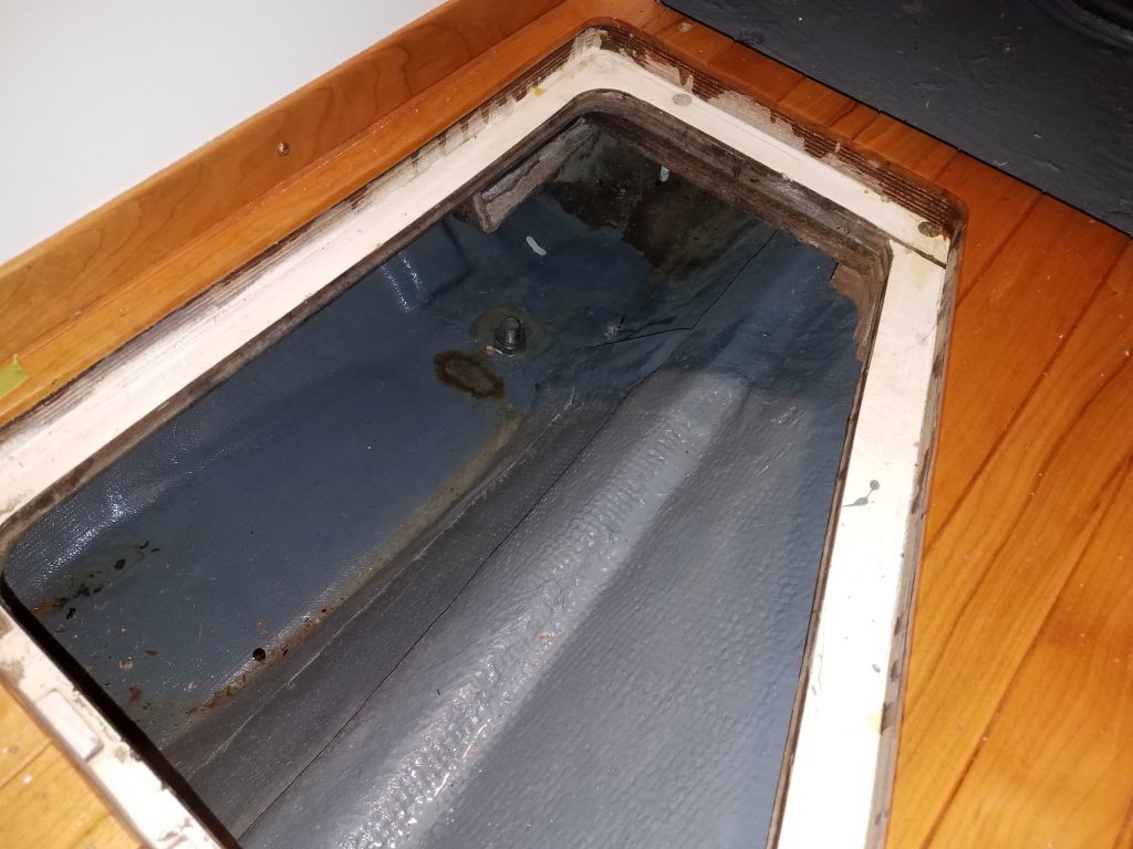
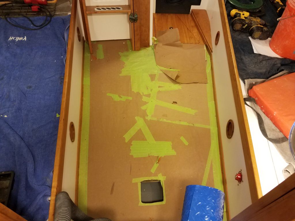
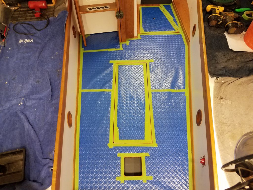
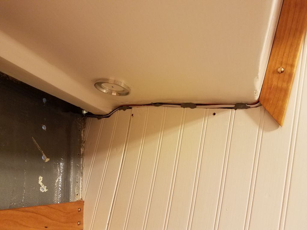
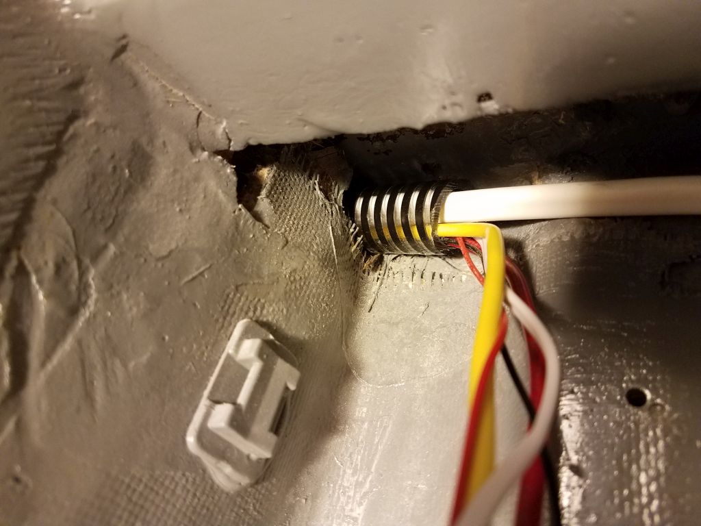
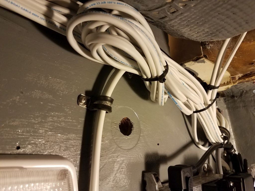
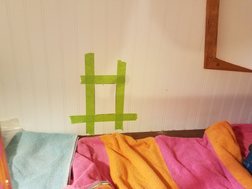
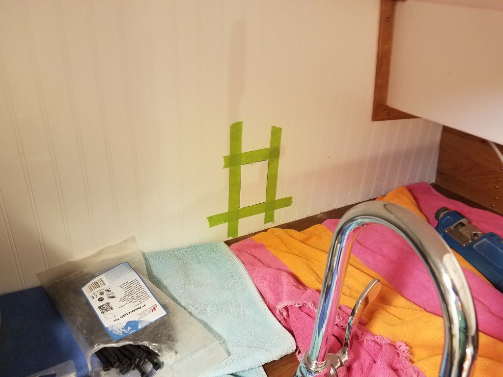
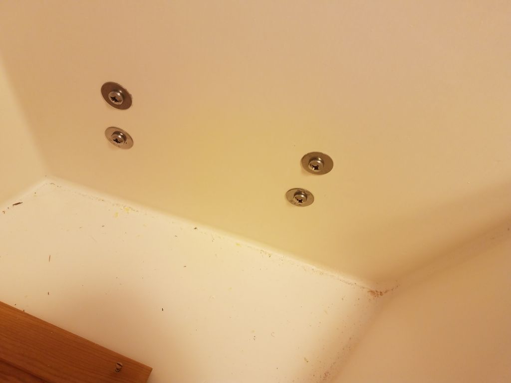
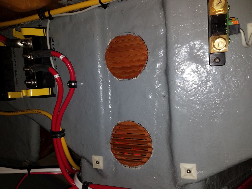
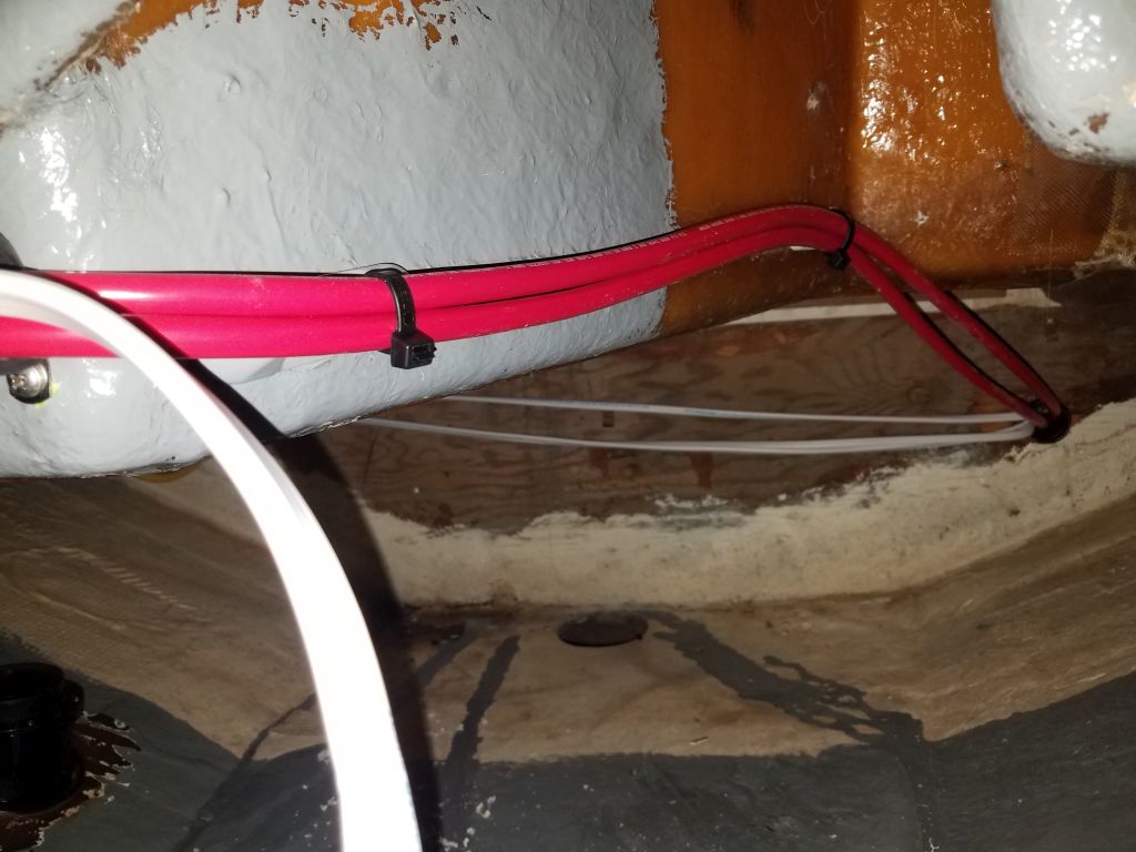
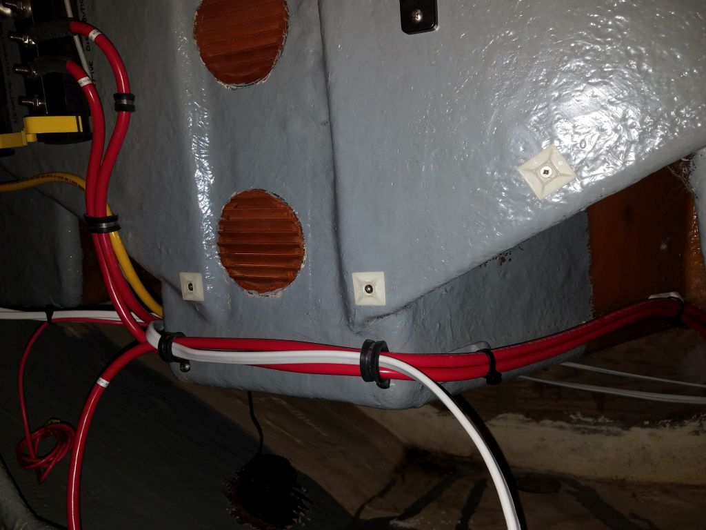
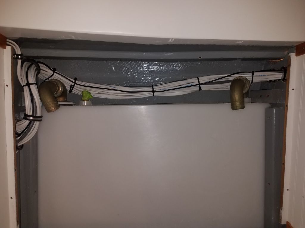
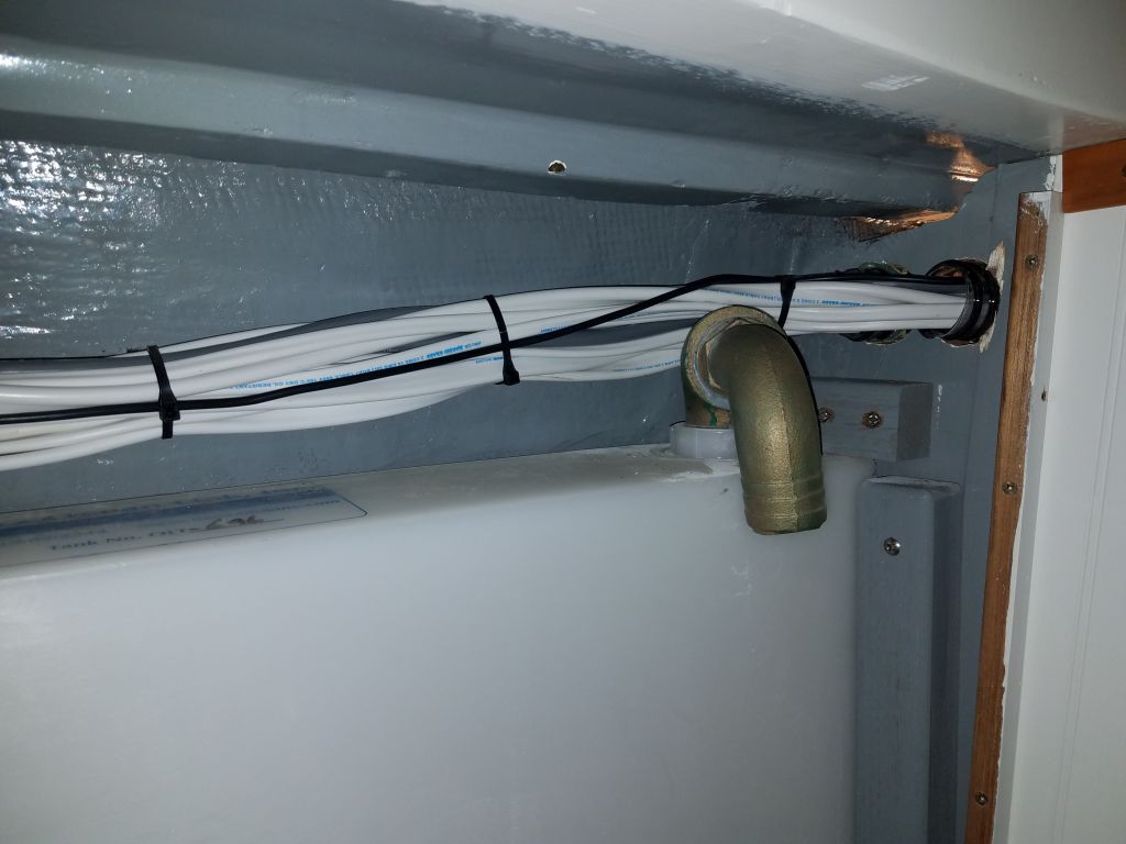
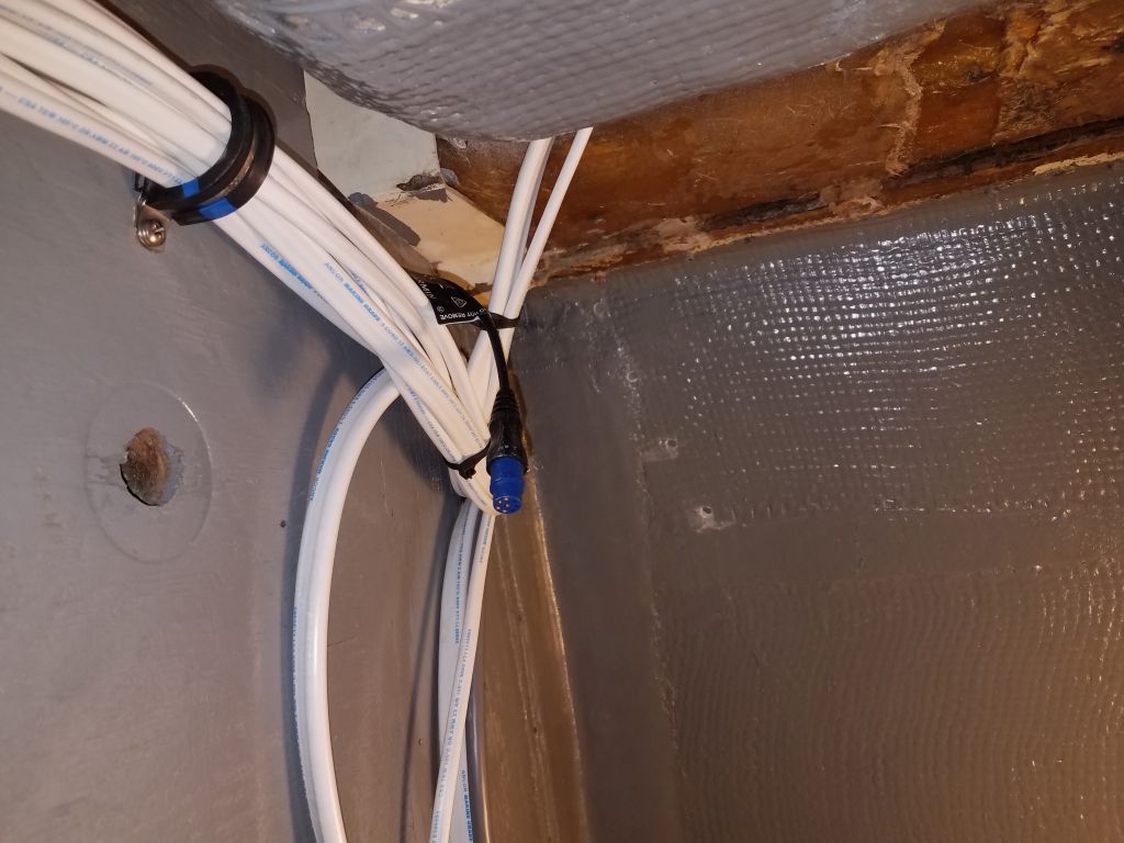
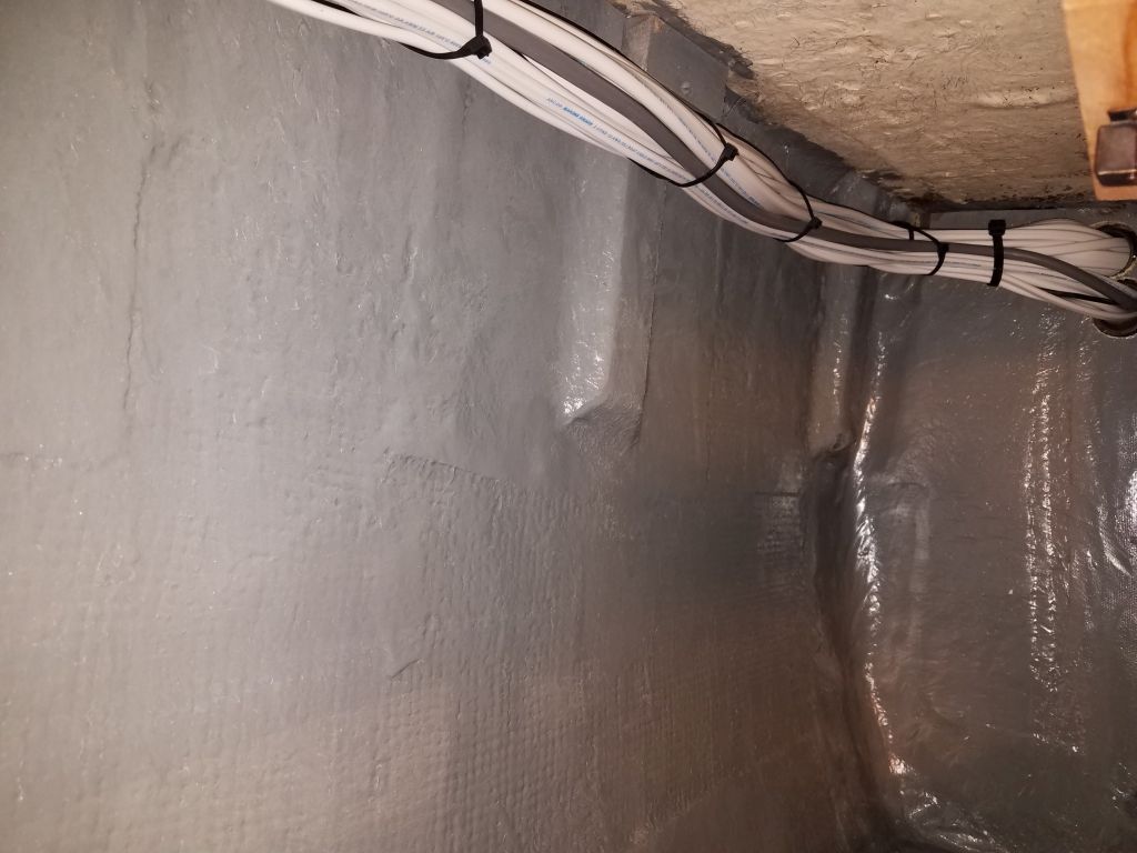
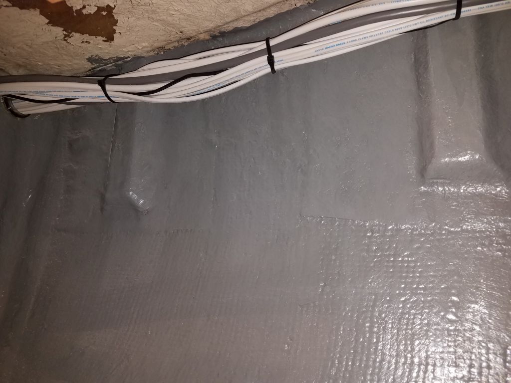
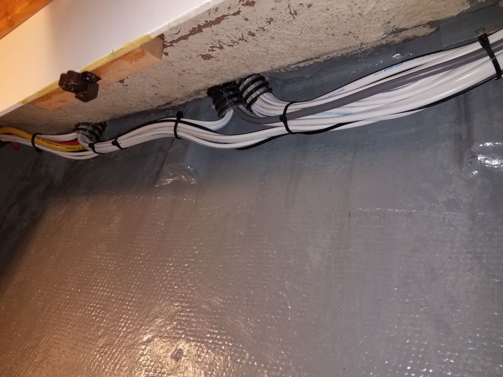
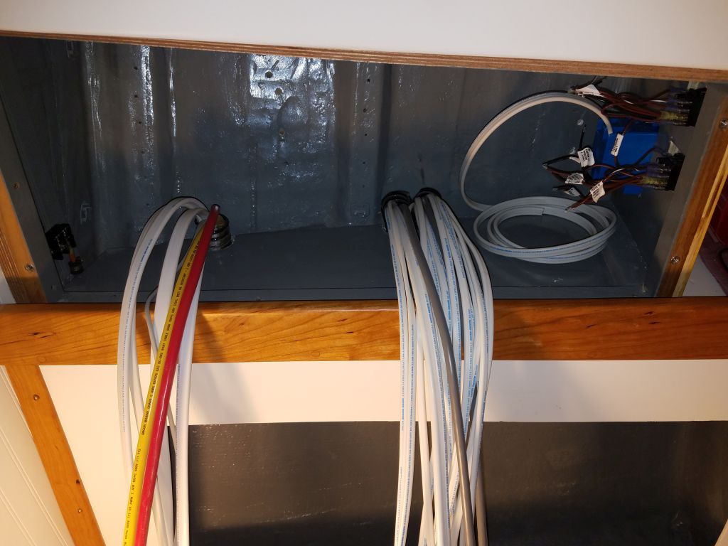
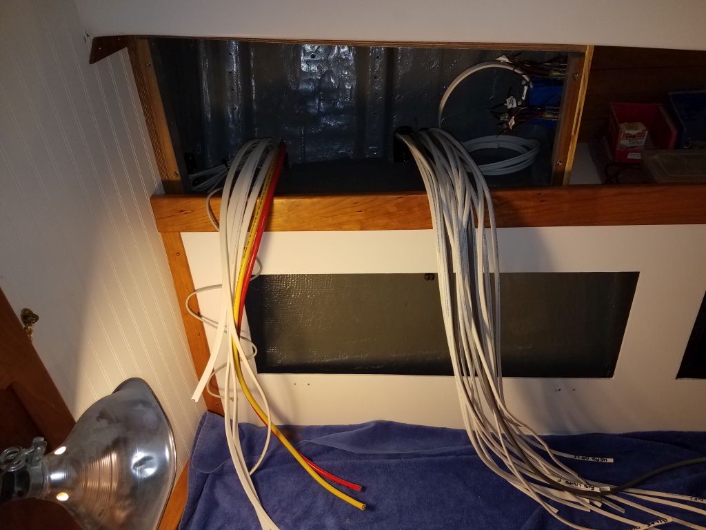
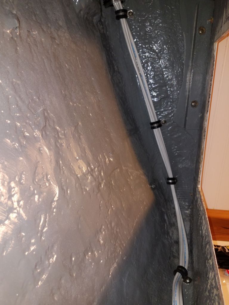
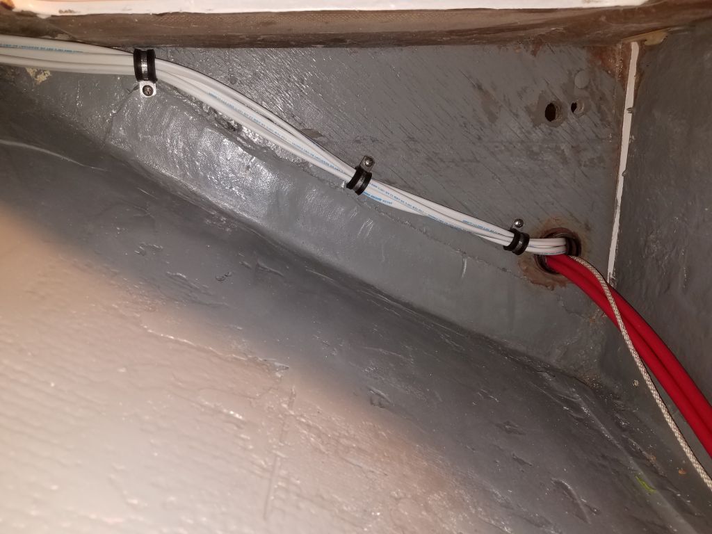
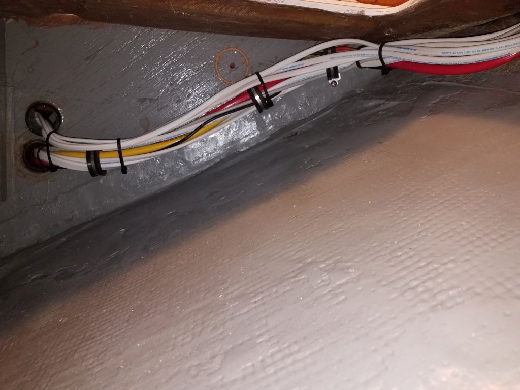
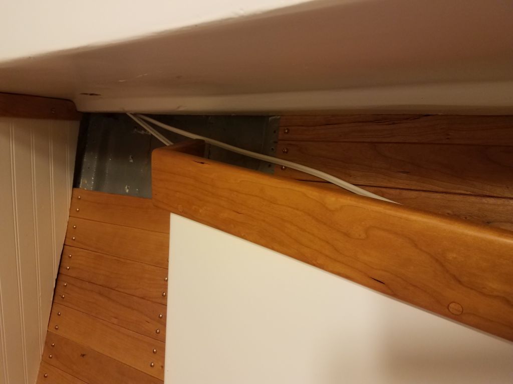
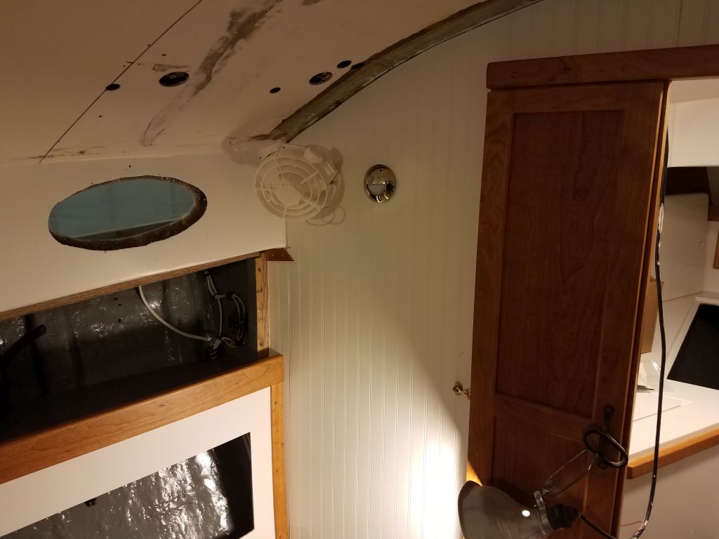
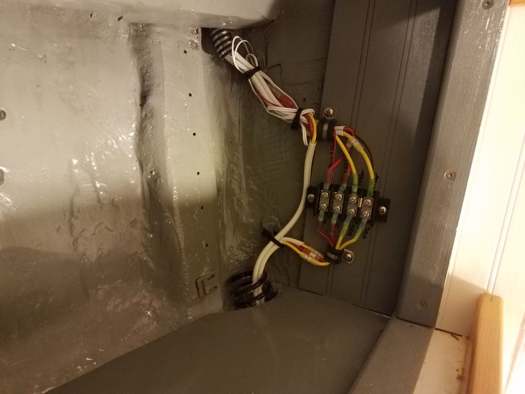
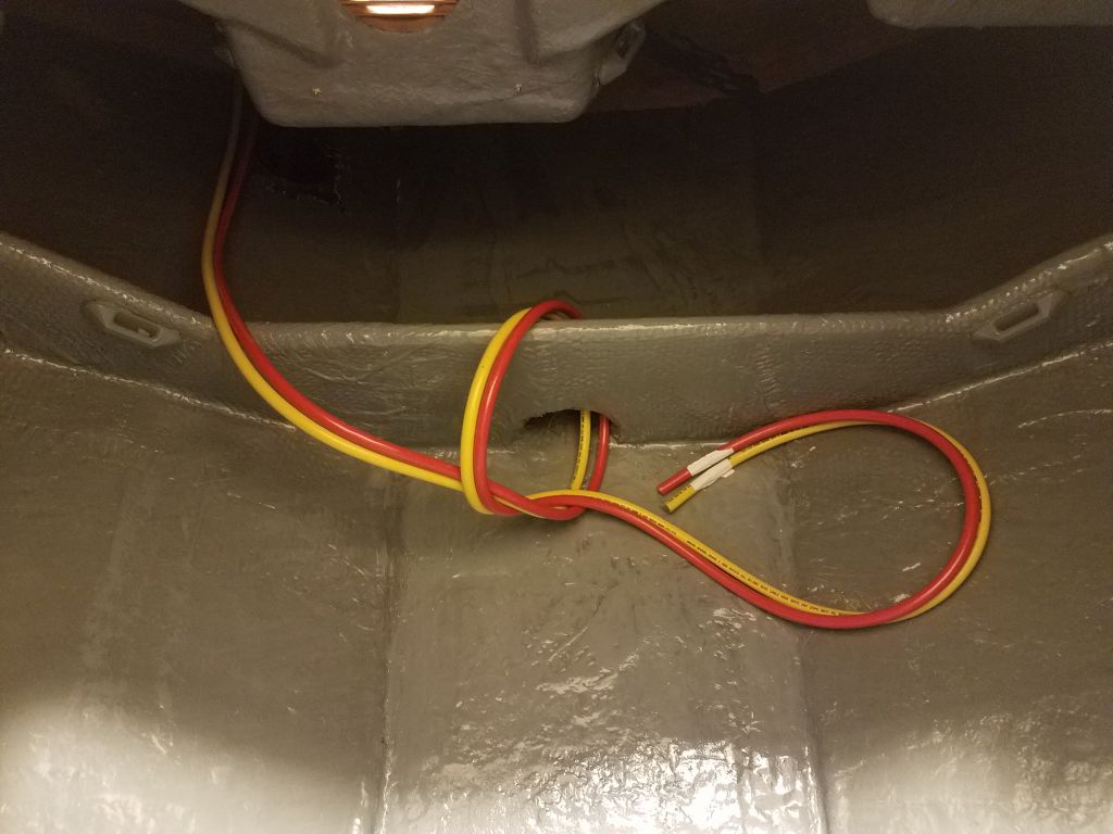
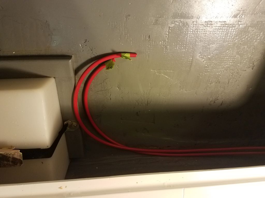
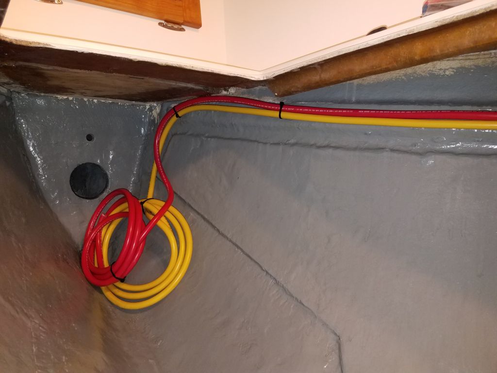
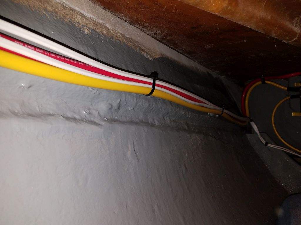
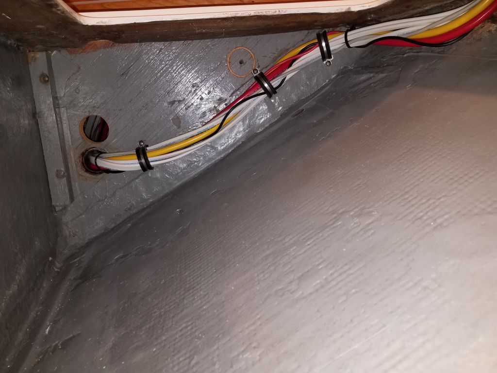
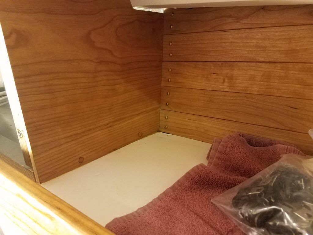
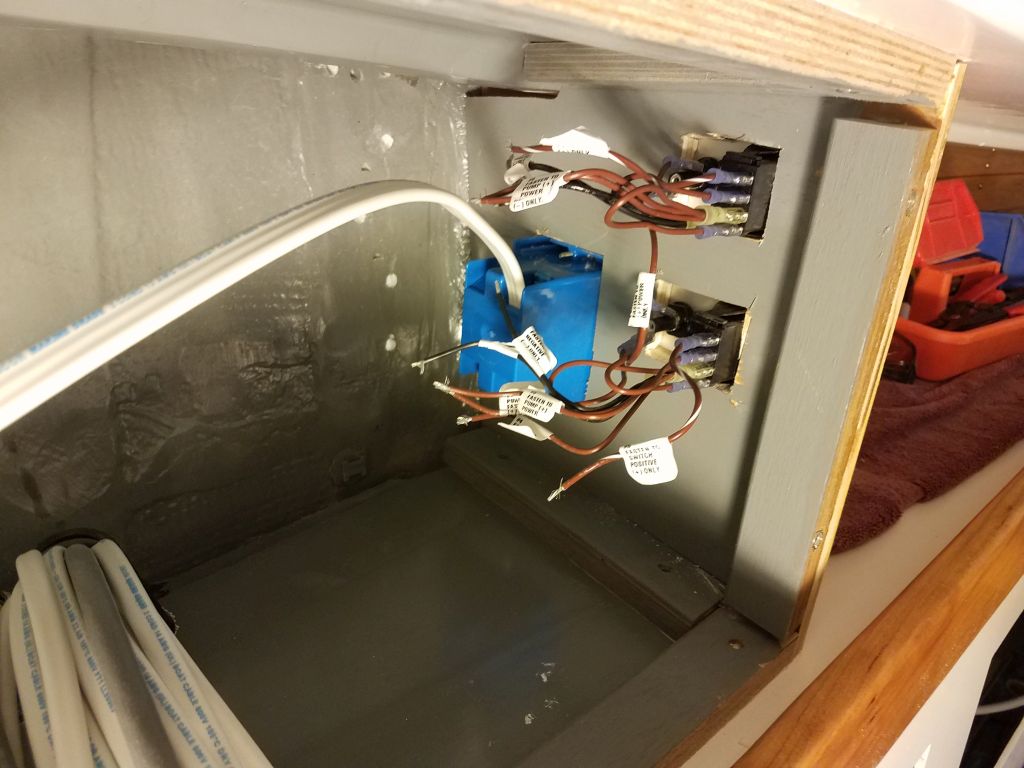
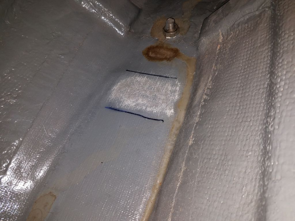
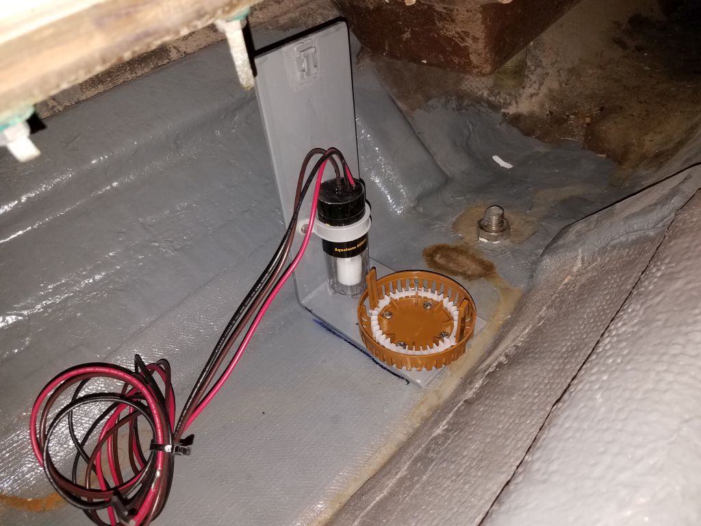
Inside the boat, in the bilge opening near the galley, I chose the location for the bracket and removed paint from the bottom of the bilge so I could epoxy the bracket in place. This location allowed relatively easy access for wiring and servicing the pump and switch in the future, and the bracket design intended for the wiring to be easily led up and away from the bilge water, where I could make all connections in a dry location.There was room on each side of the bracket to allow free passage of water towards the aftermost part of the bilge in the engine room, which was the deepest part and where I planned to install the switch and suction for the everyday “nuisance water” pump.
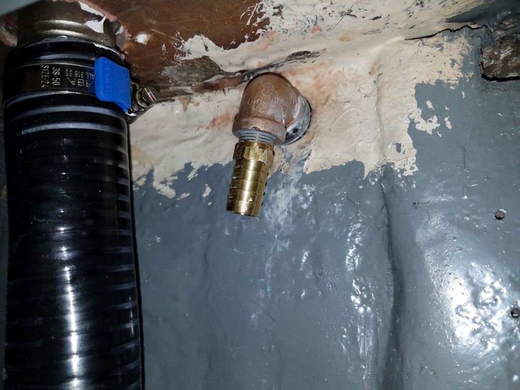
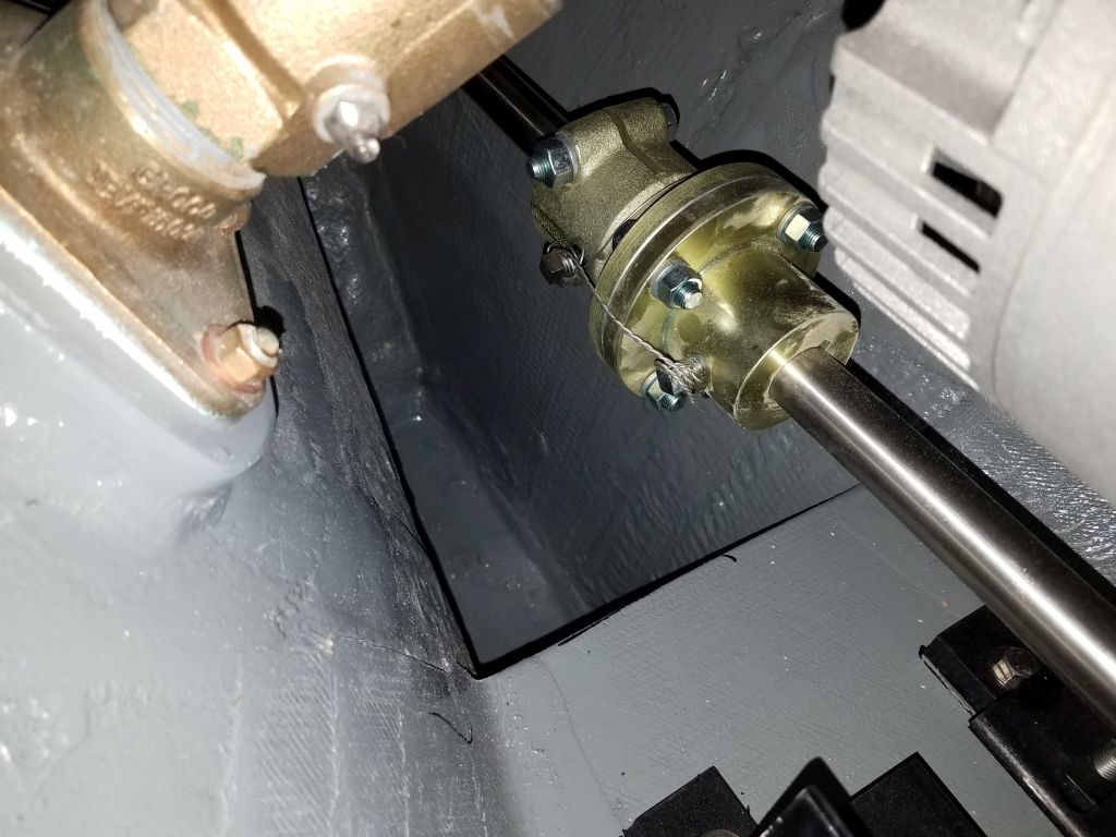
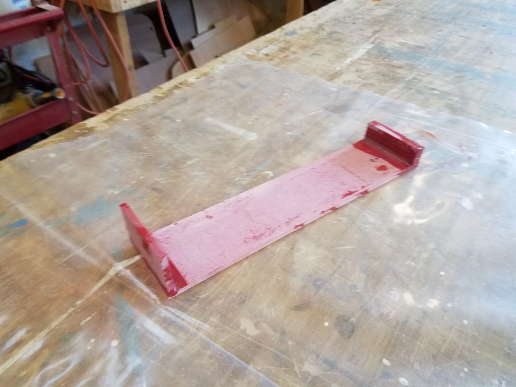
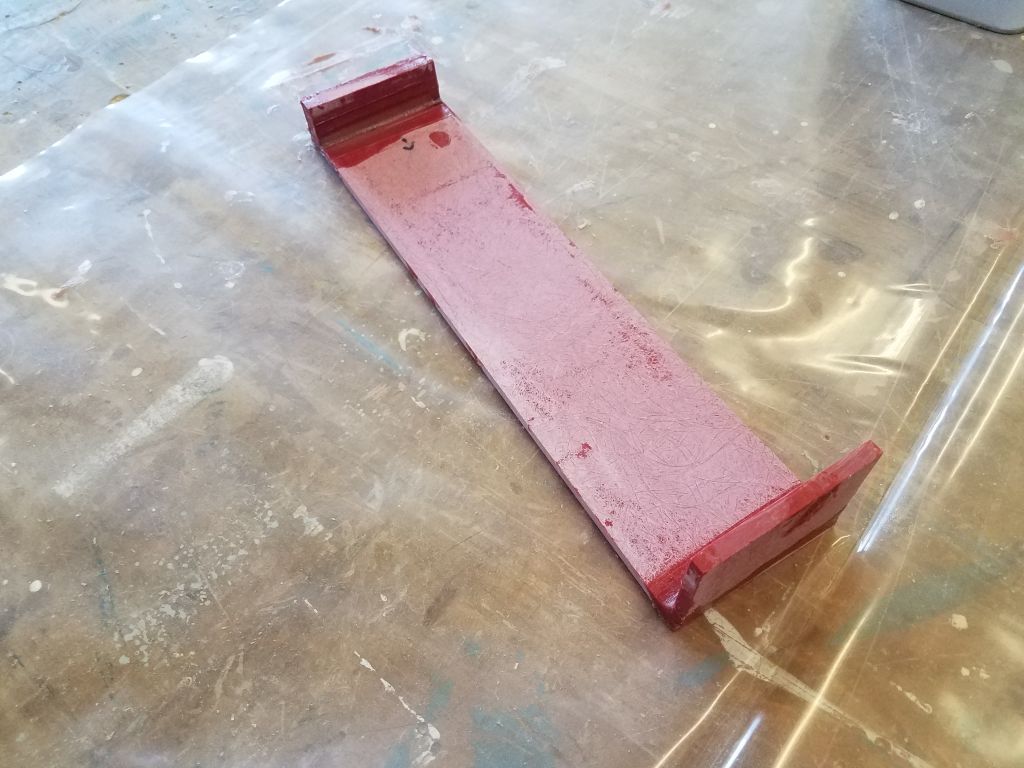
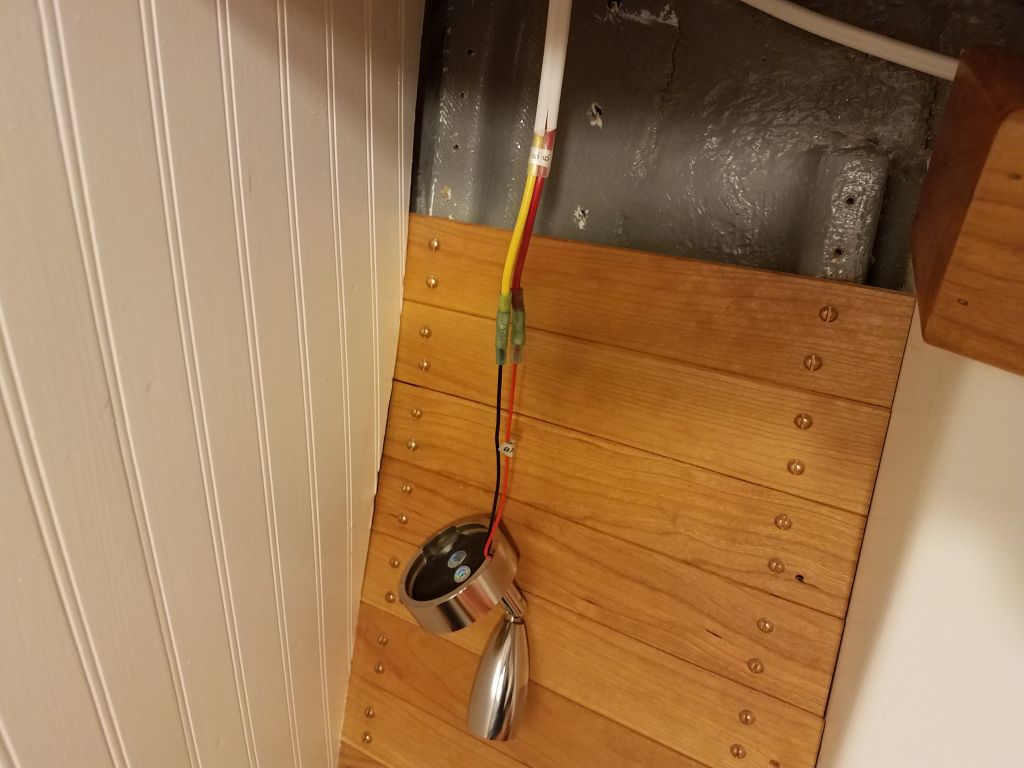
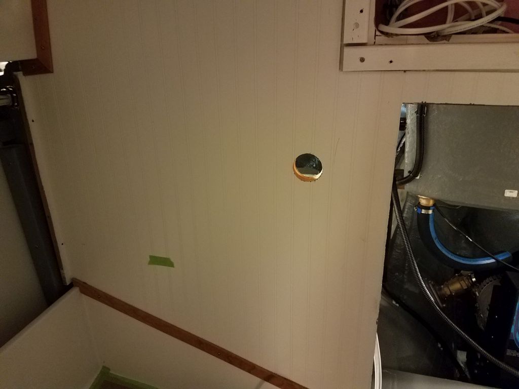
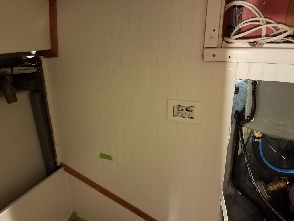
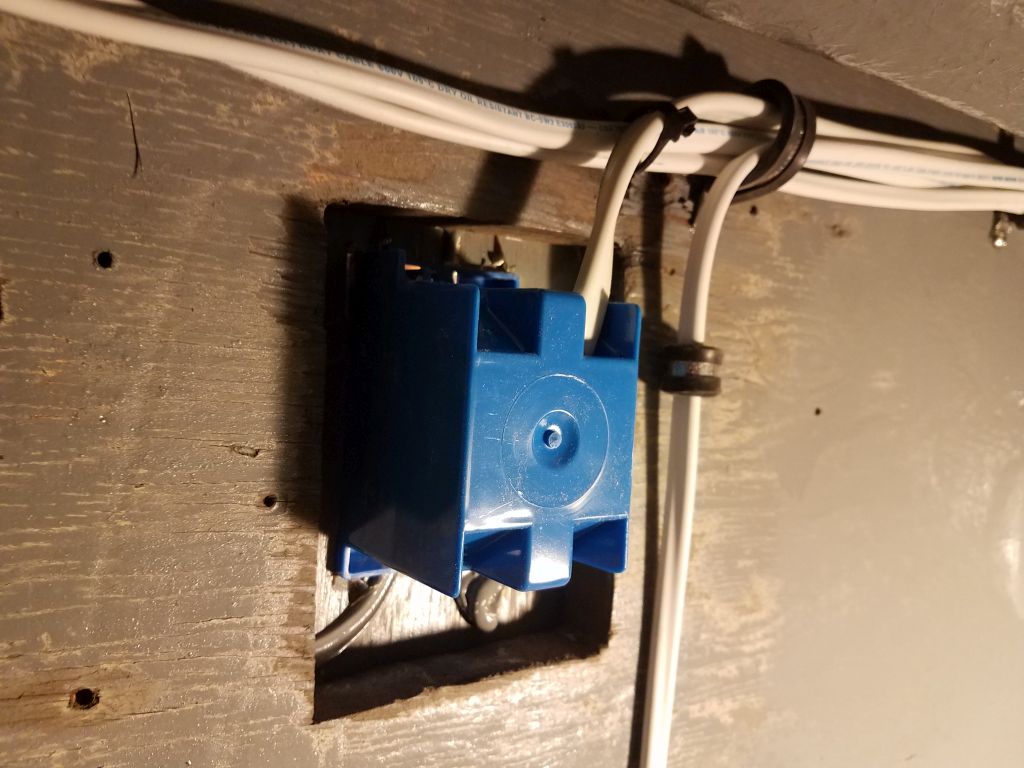
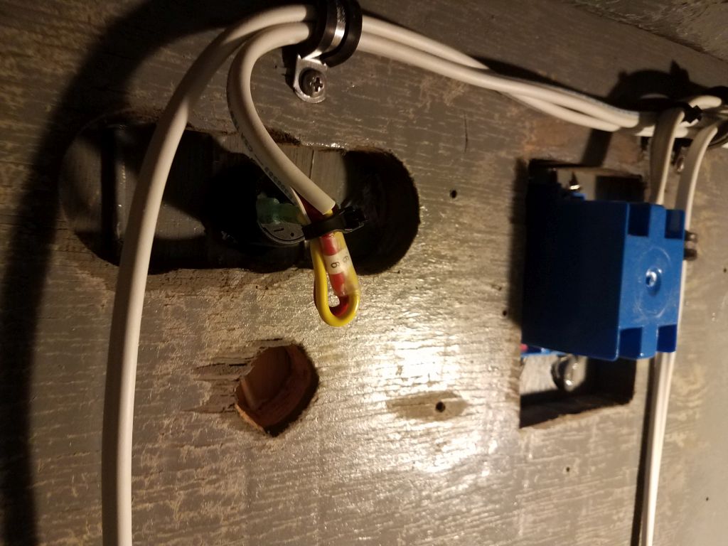
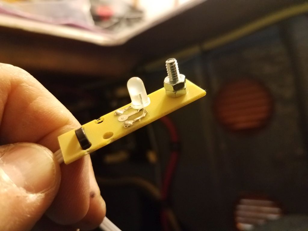
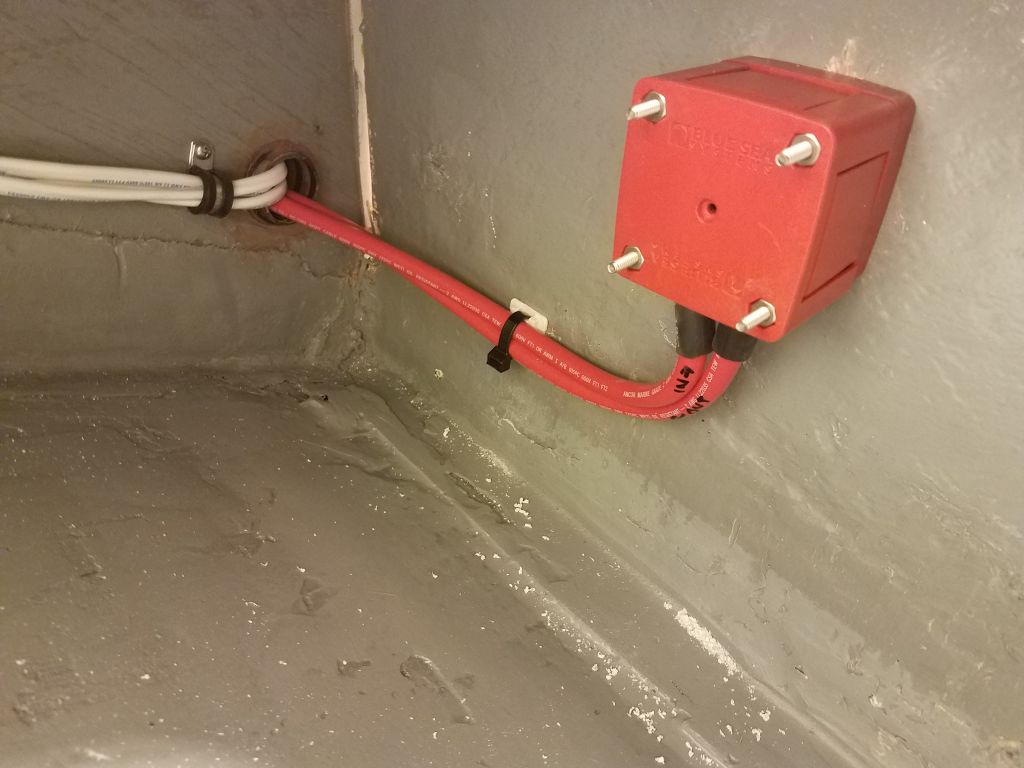
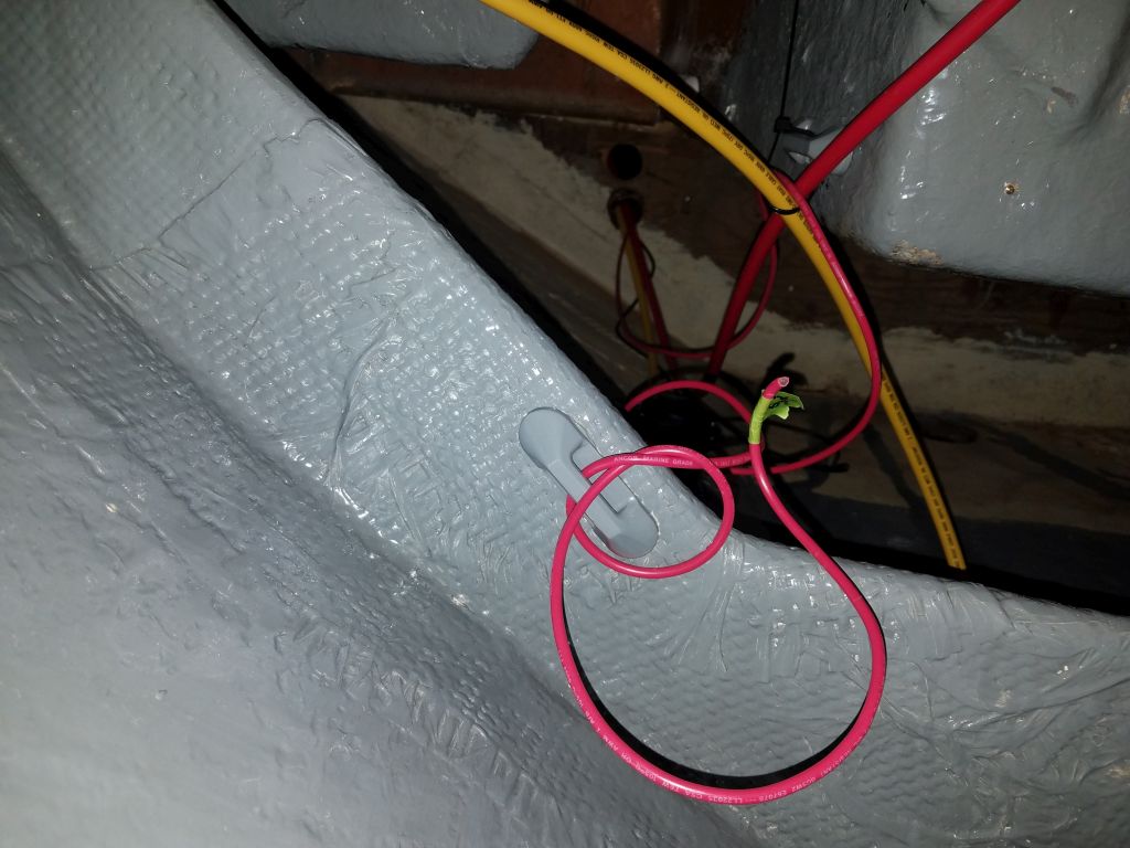
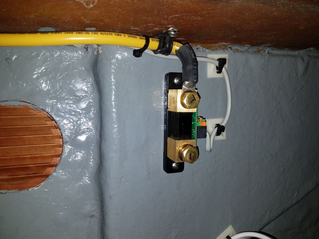
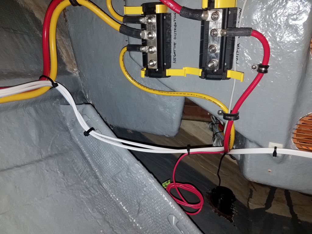
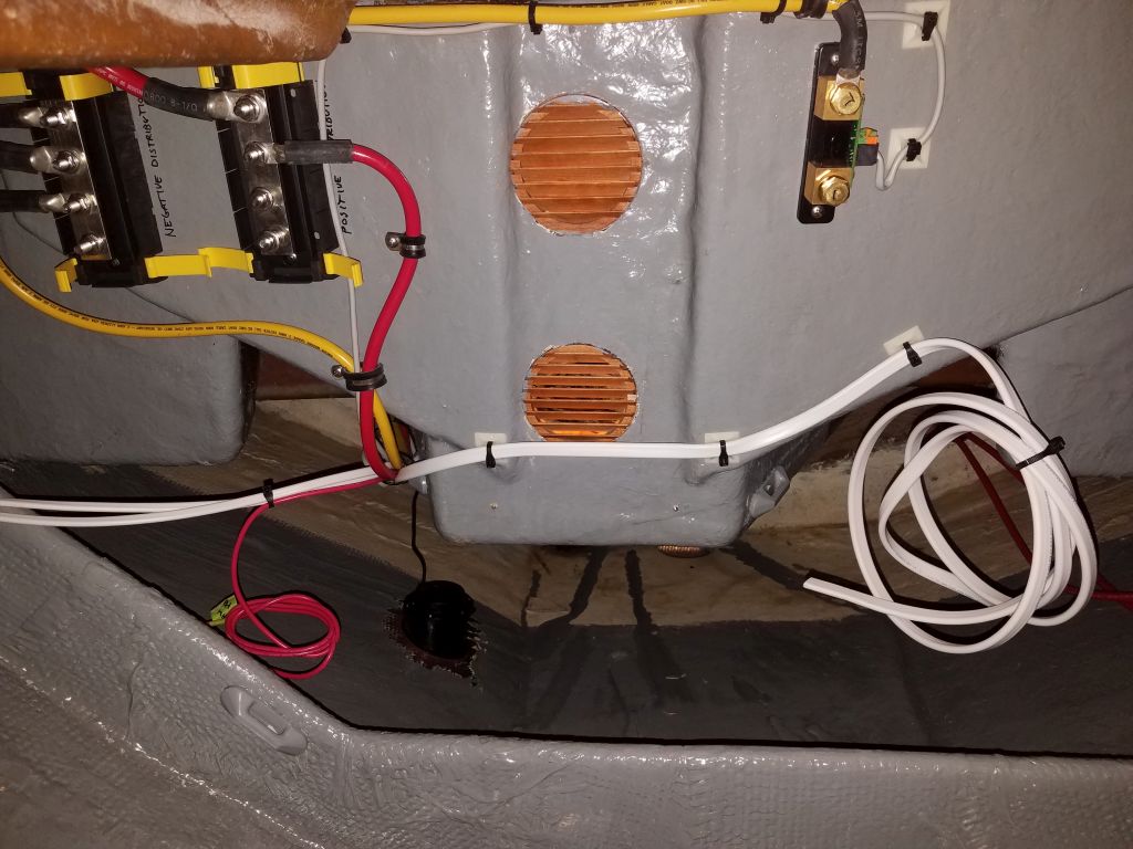
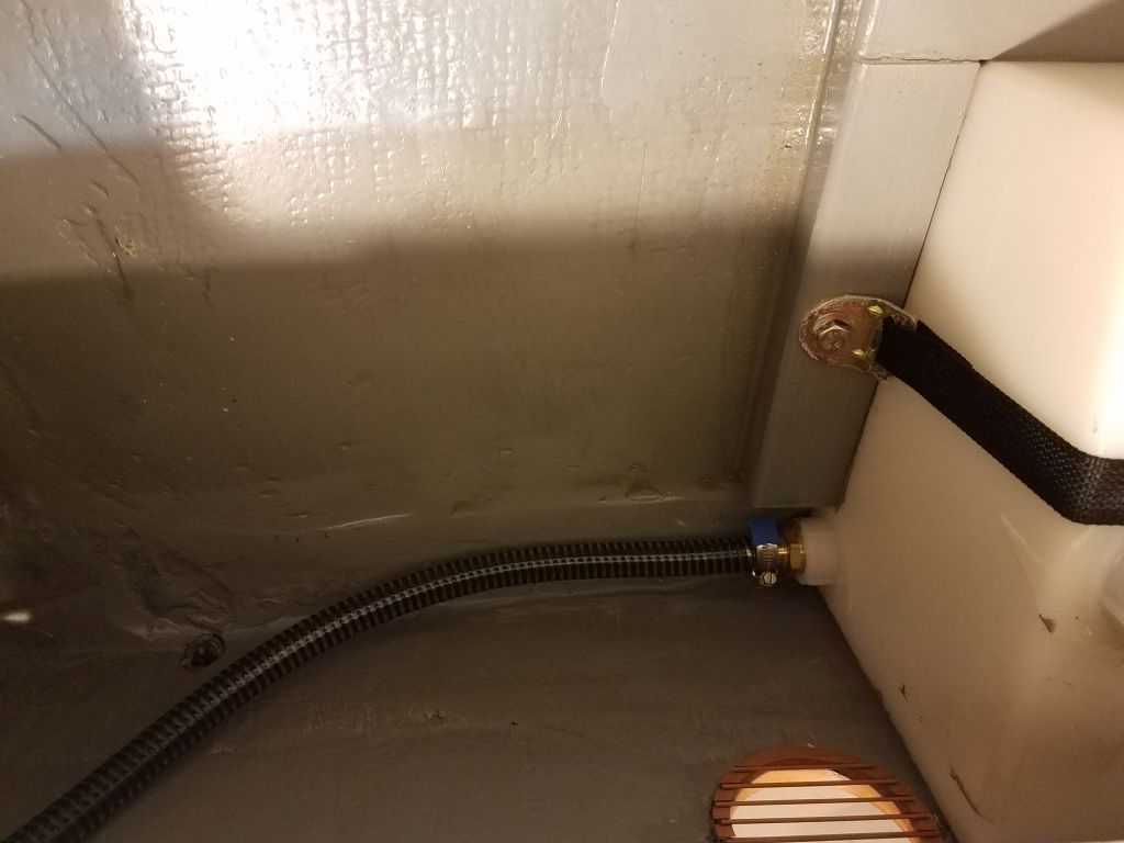
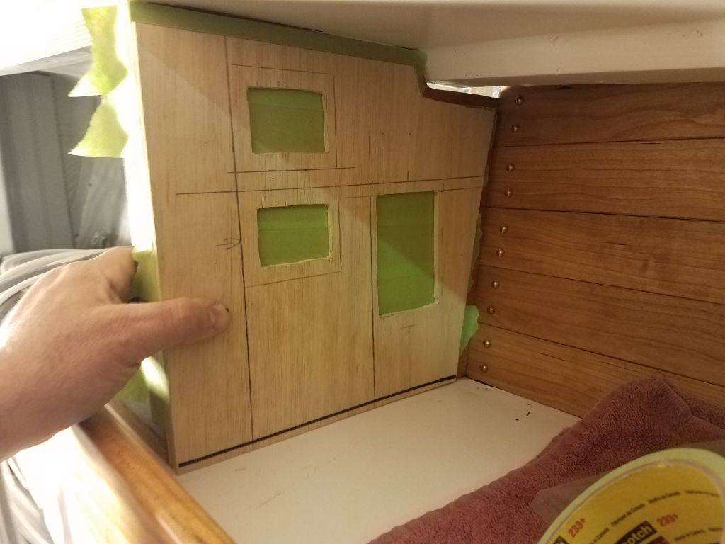
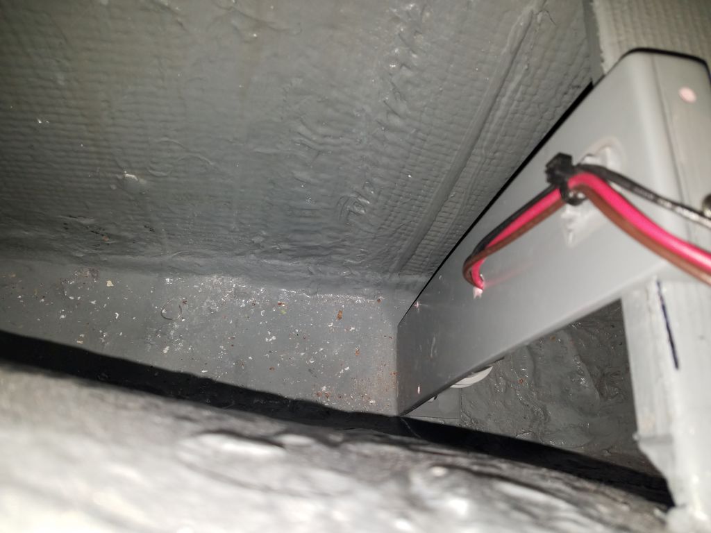
To that end, I installed the second switch on the bracket I’d made for the engine room space, then installed the bracket to the aft edge of the engine platform with a screw. I’d hoped to use two screws, but the shaft above prevented accessing the second screw location. The screw only holds the bracket upright, and there’d be no pressure on the installation, so the single screw was ample in any event. I noted earlier that I’d mistakenly built the bracket backwards from my intention, but this actually worked out well since now the switch was well-protected on the forward side of the bracket, leaving plenty of room behind for the manual and nuisance pump suction hoses. Final wiring runs and plumbing connections would happen in the near future.

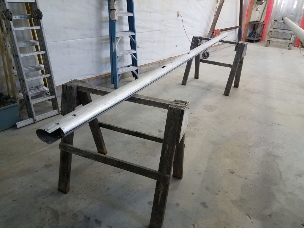
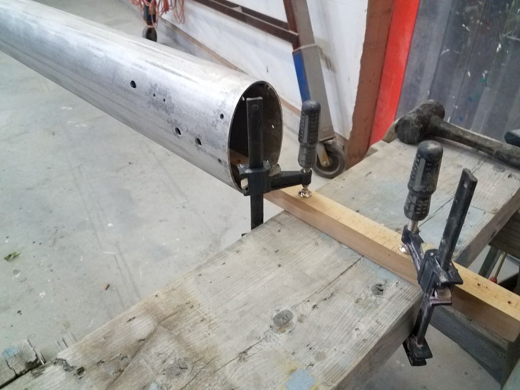
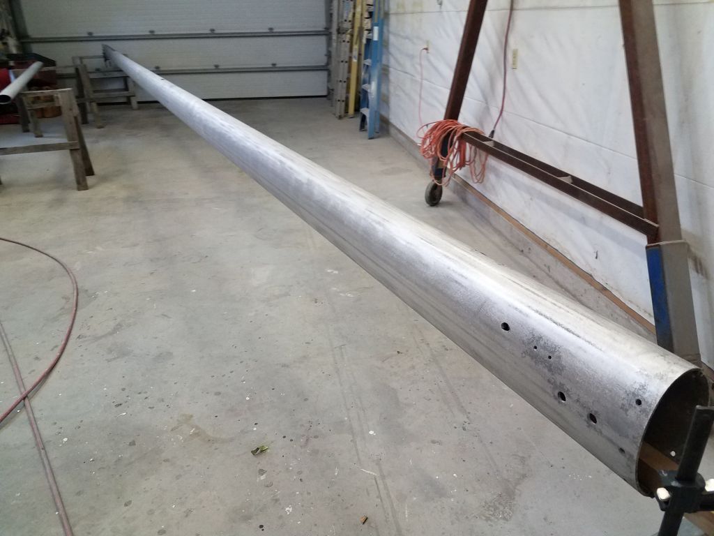
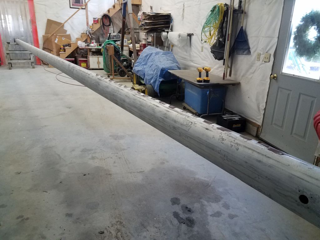
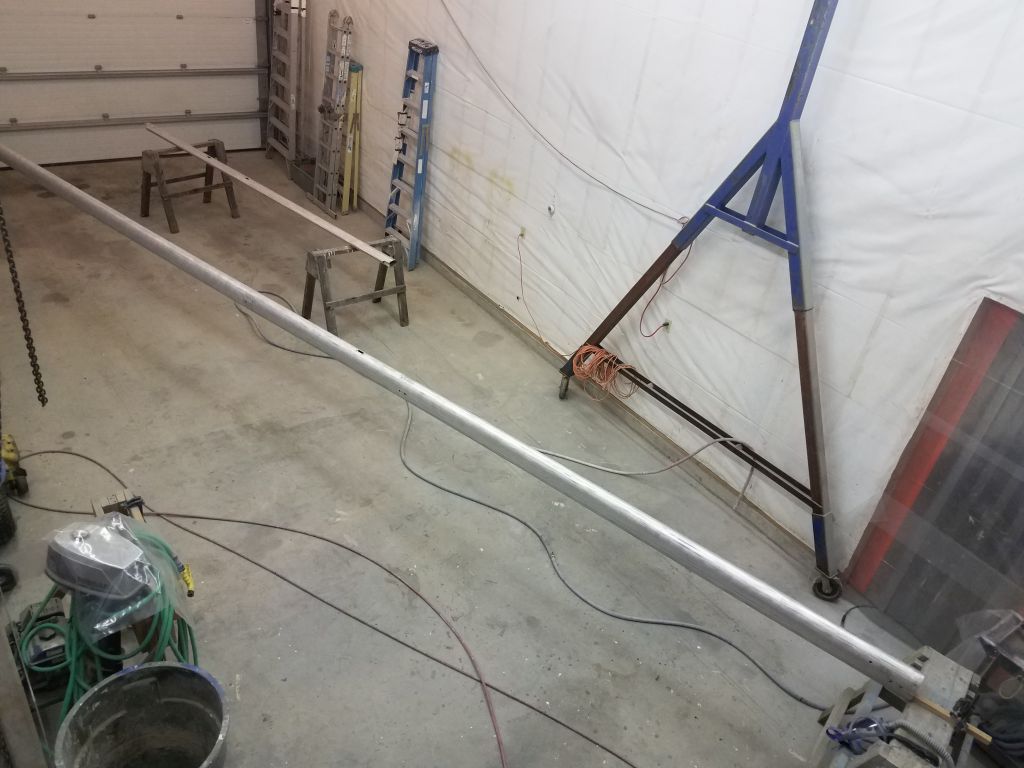
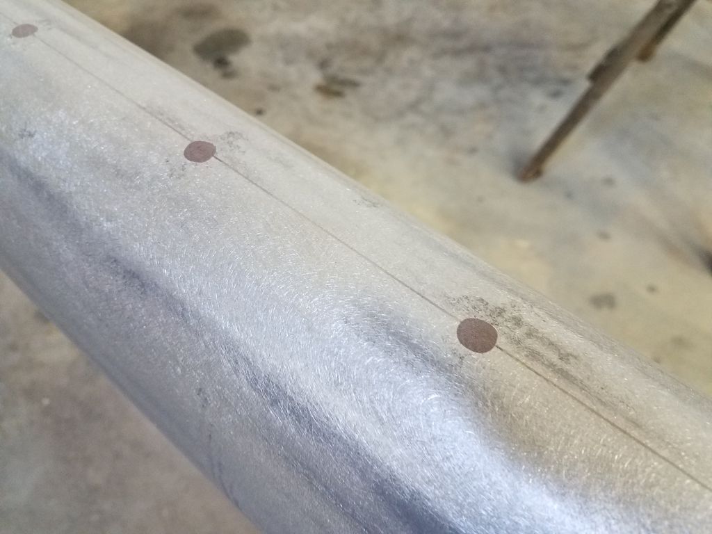
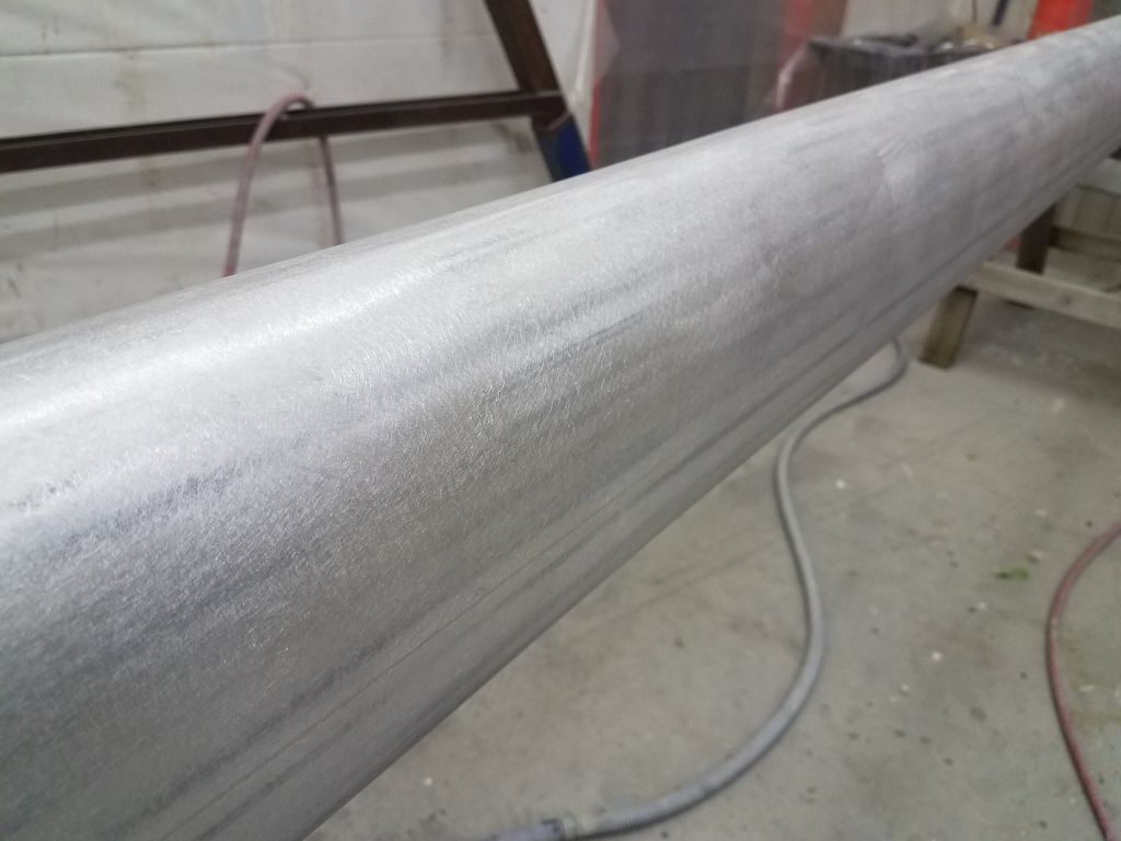
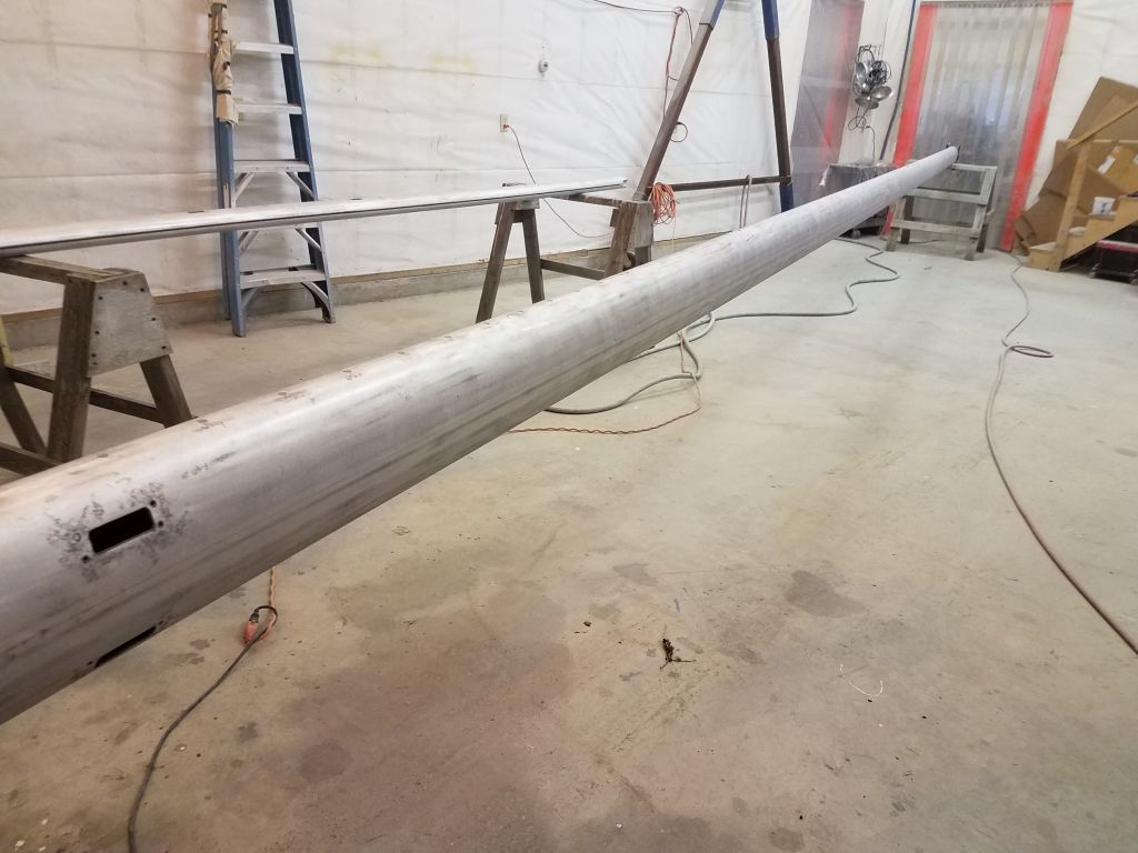
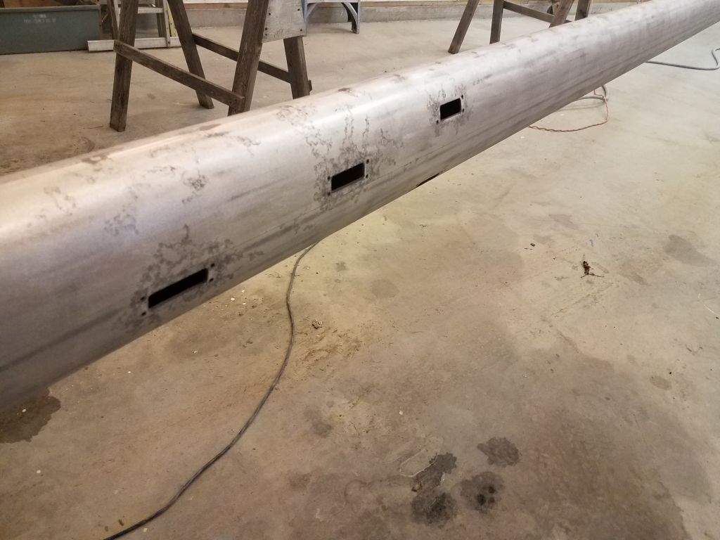
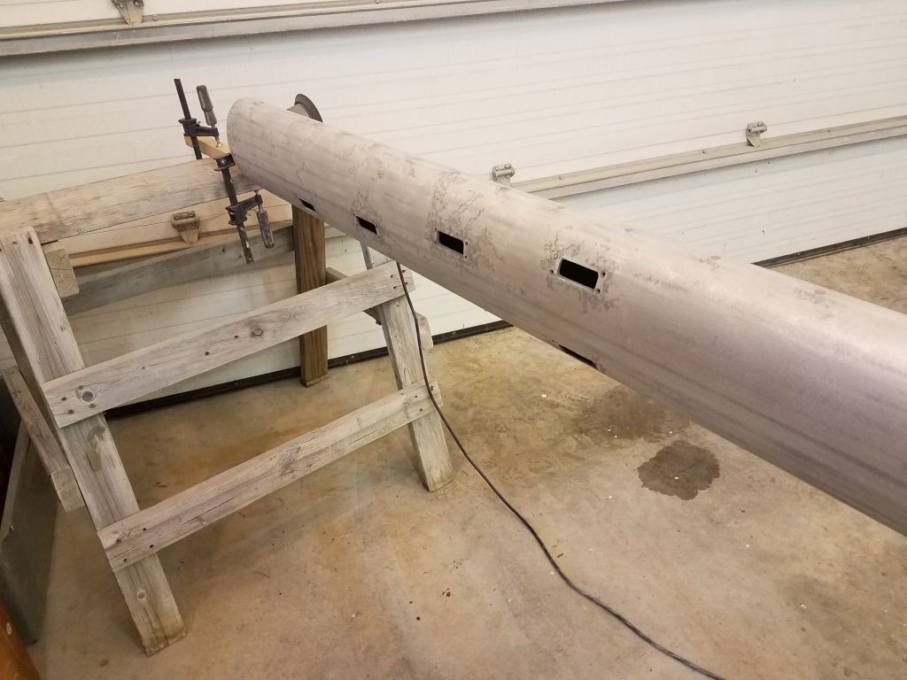
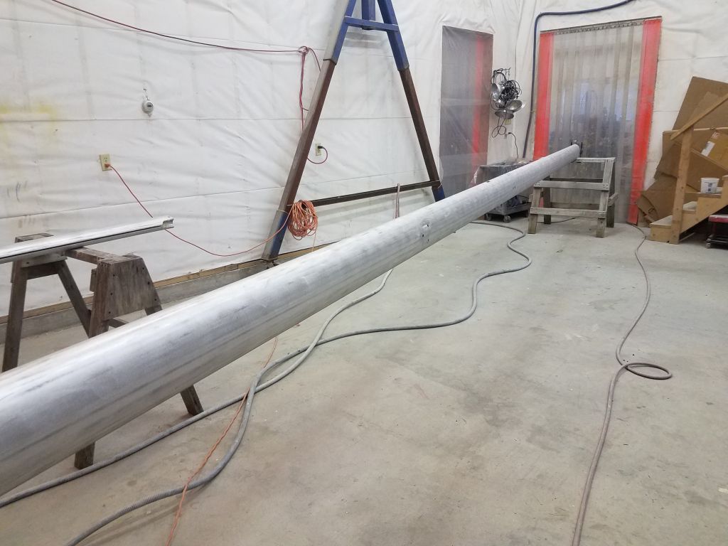
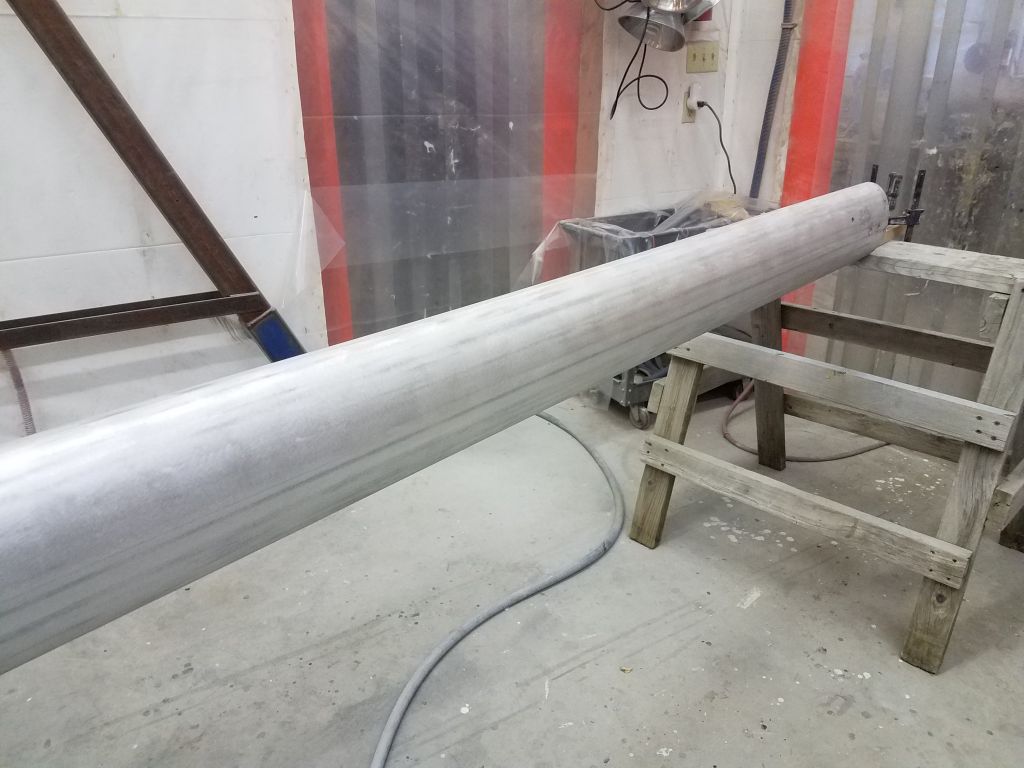
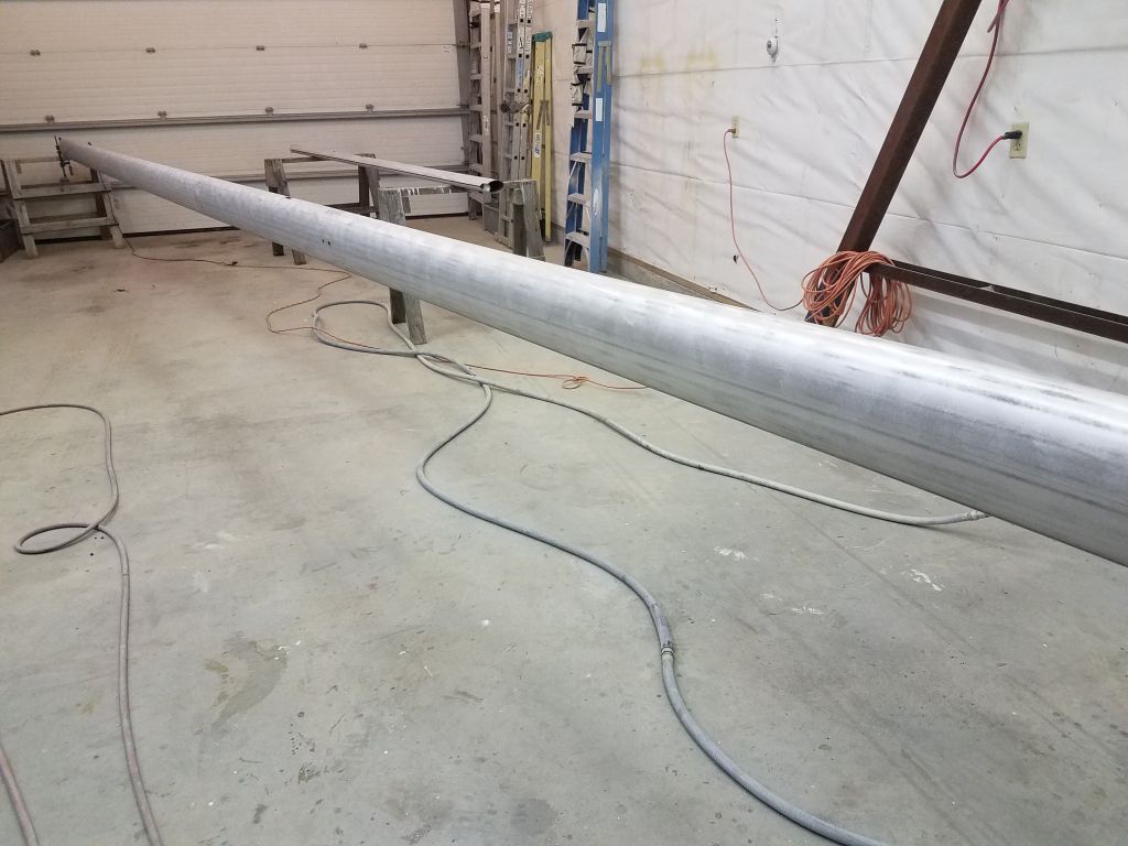
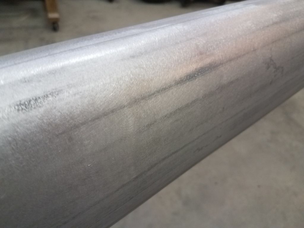
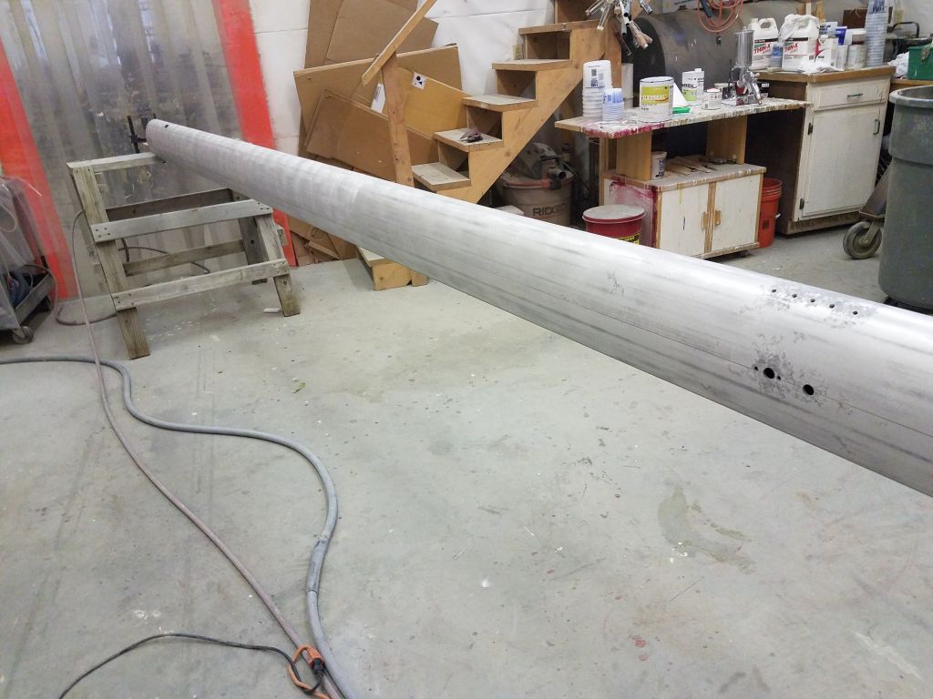
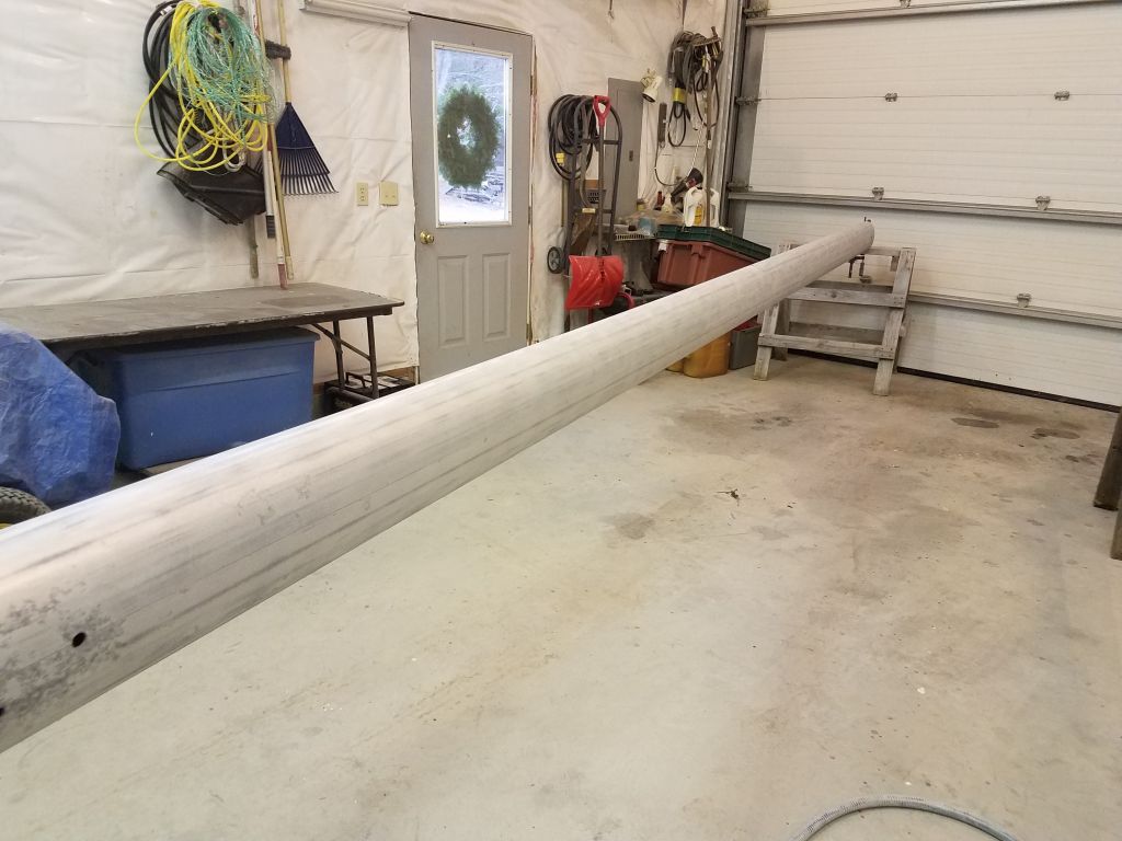
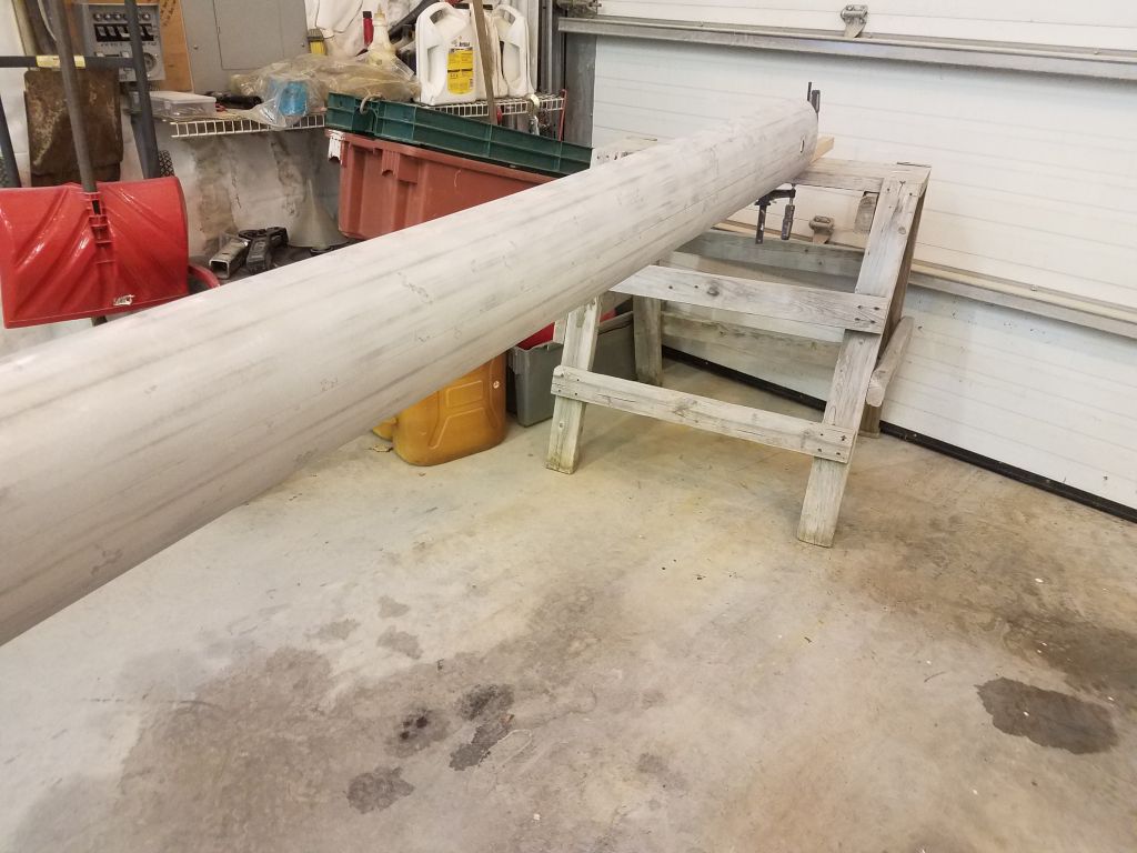
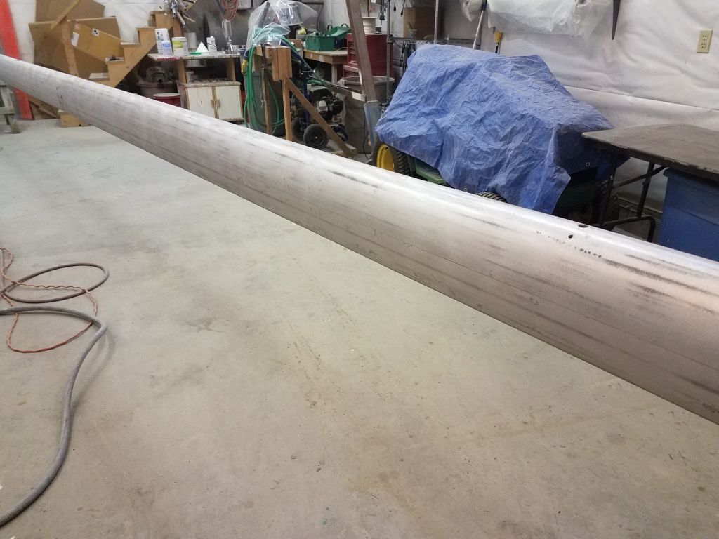
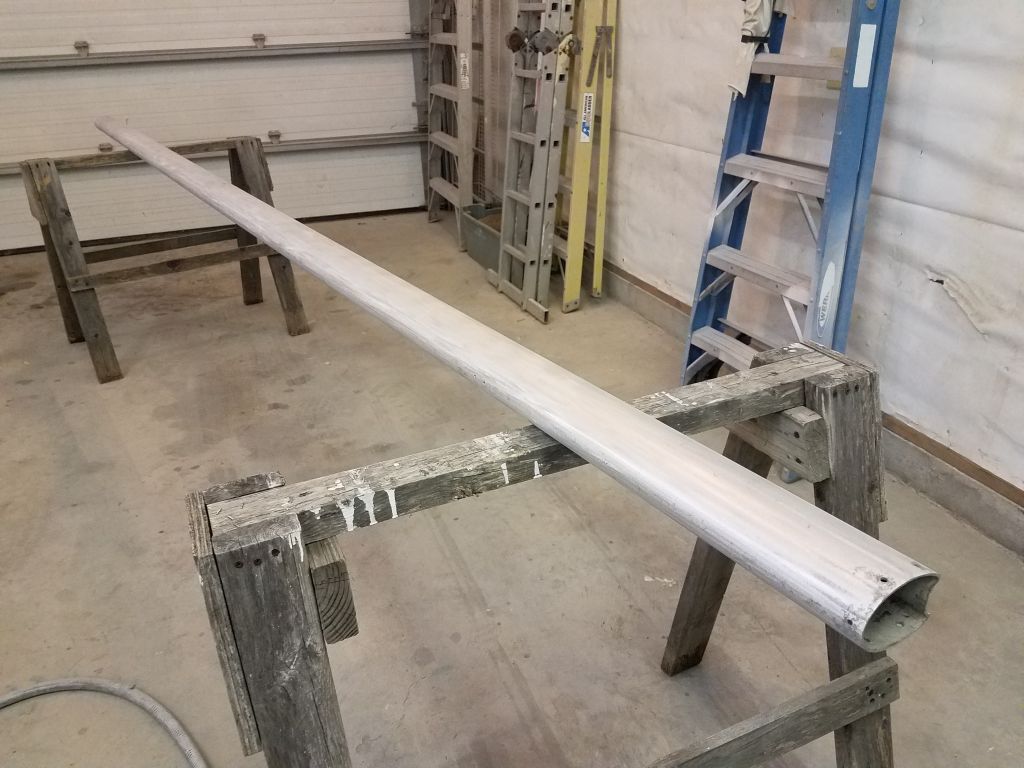
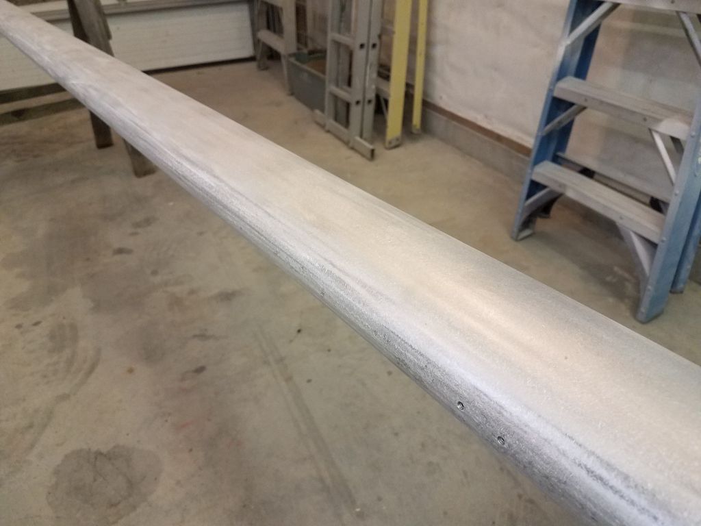
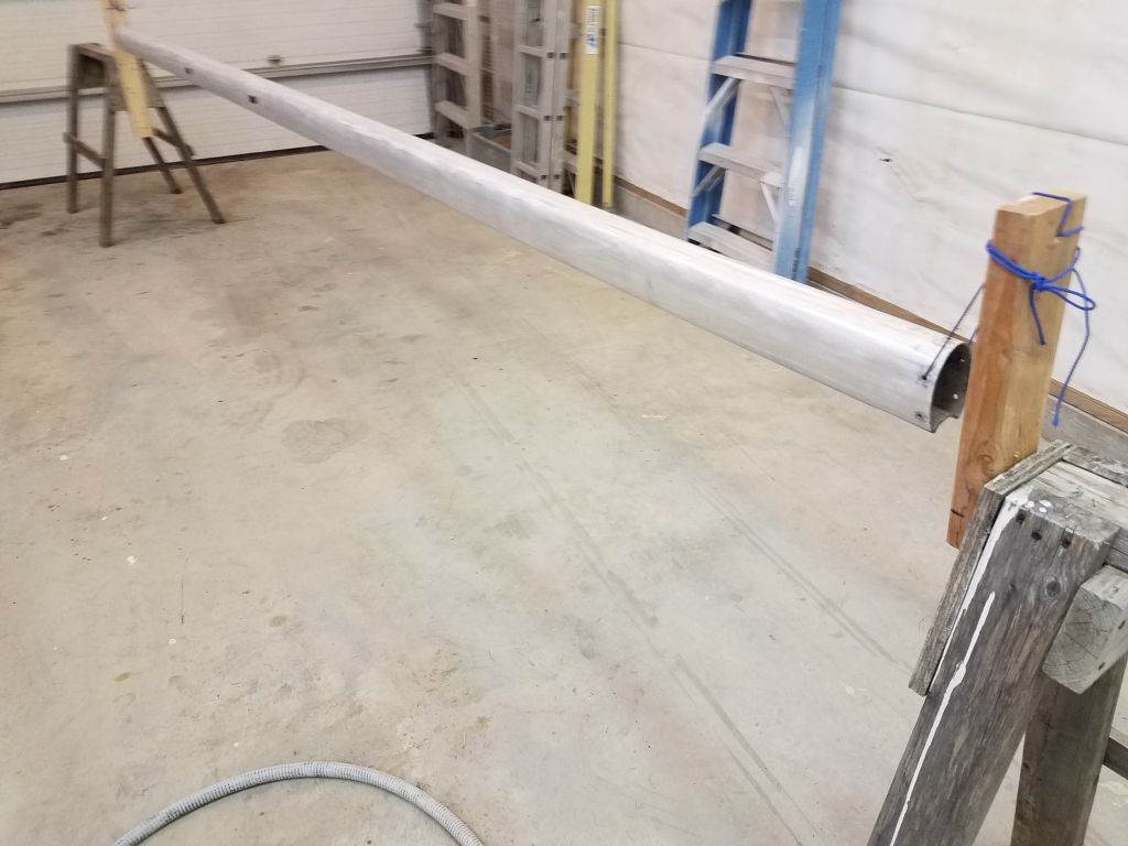
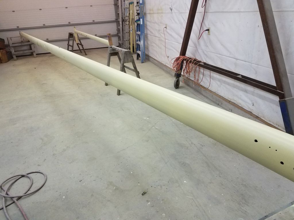
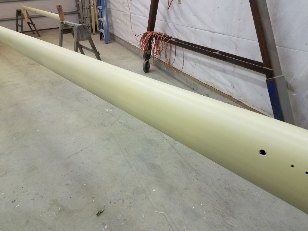
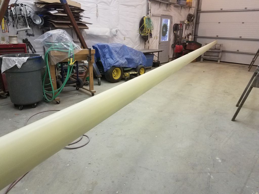
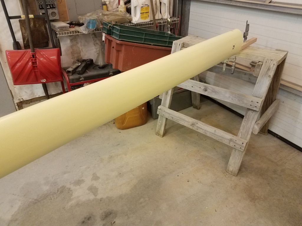
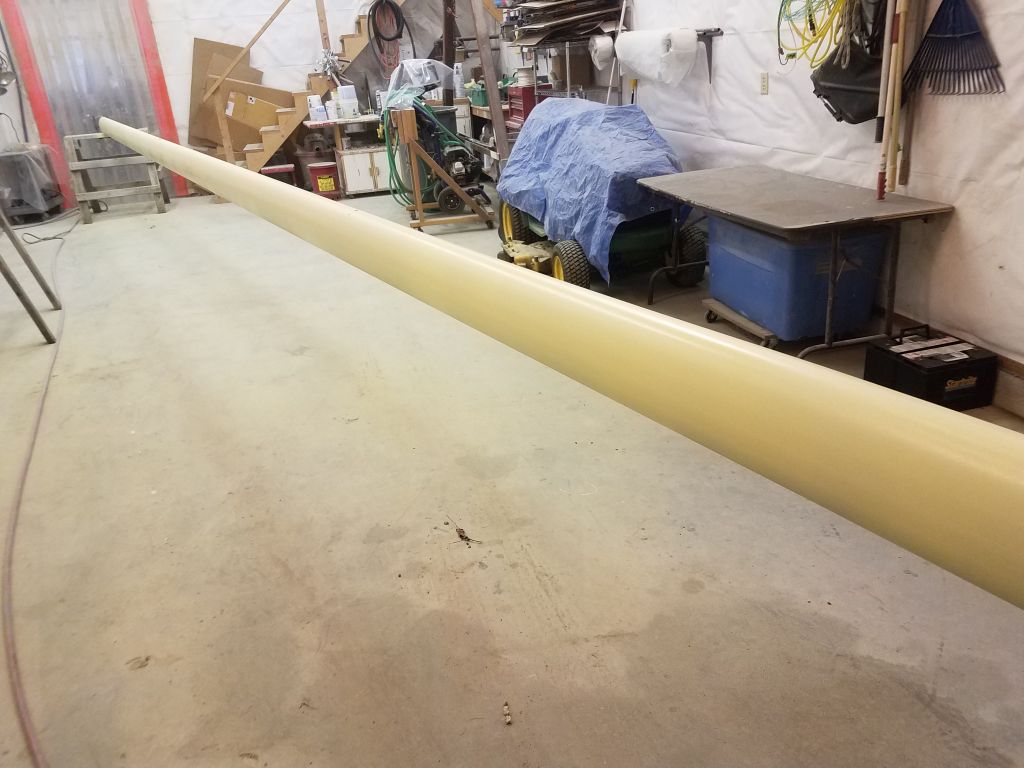
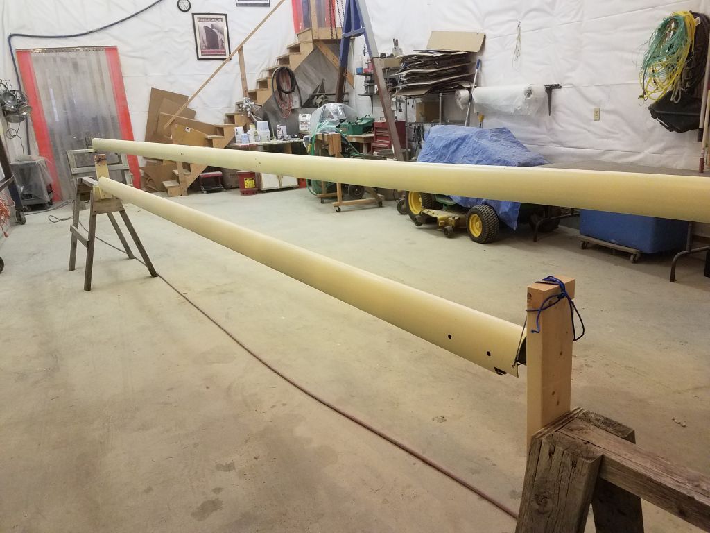
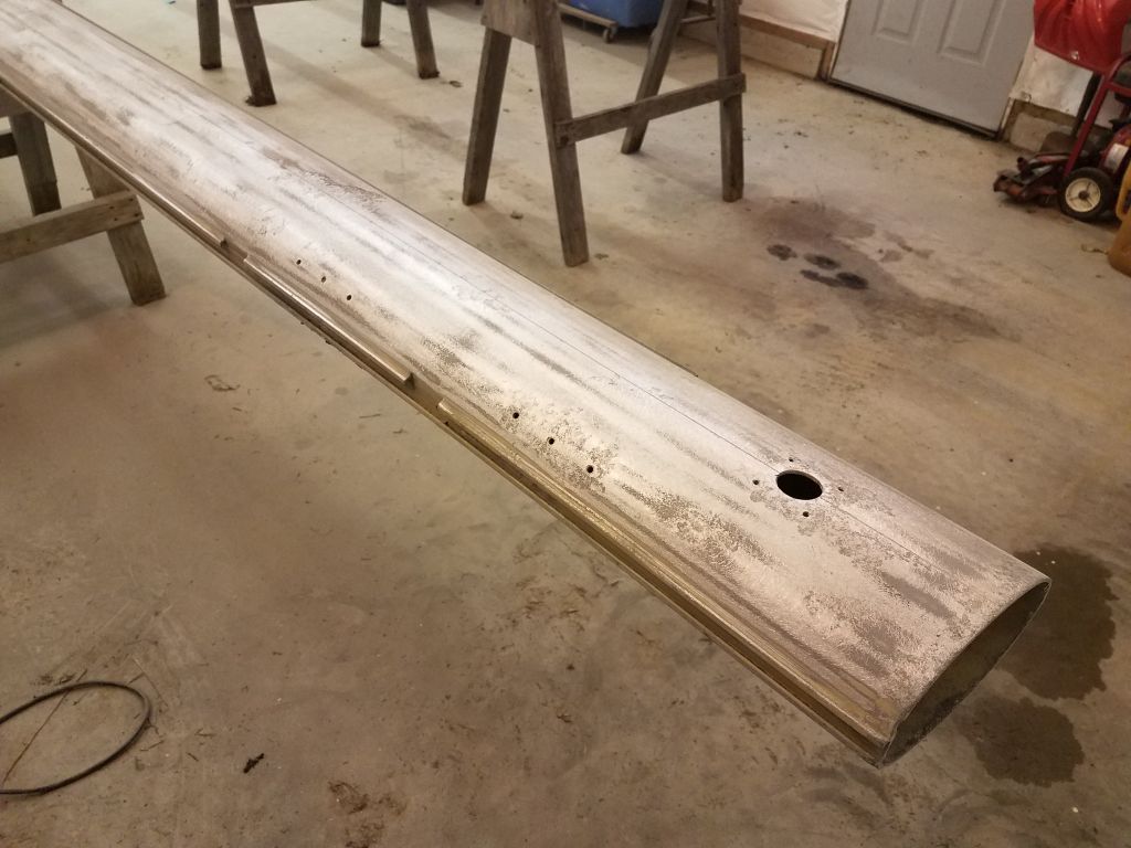
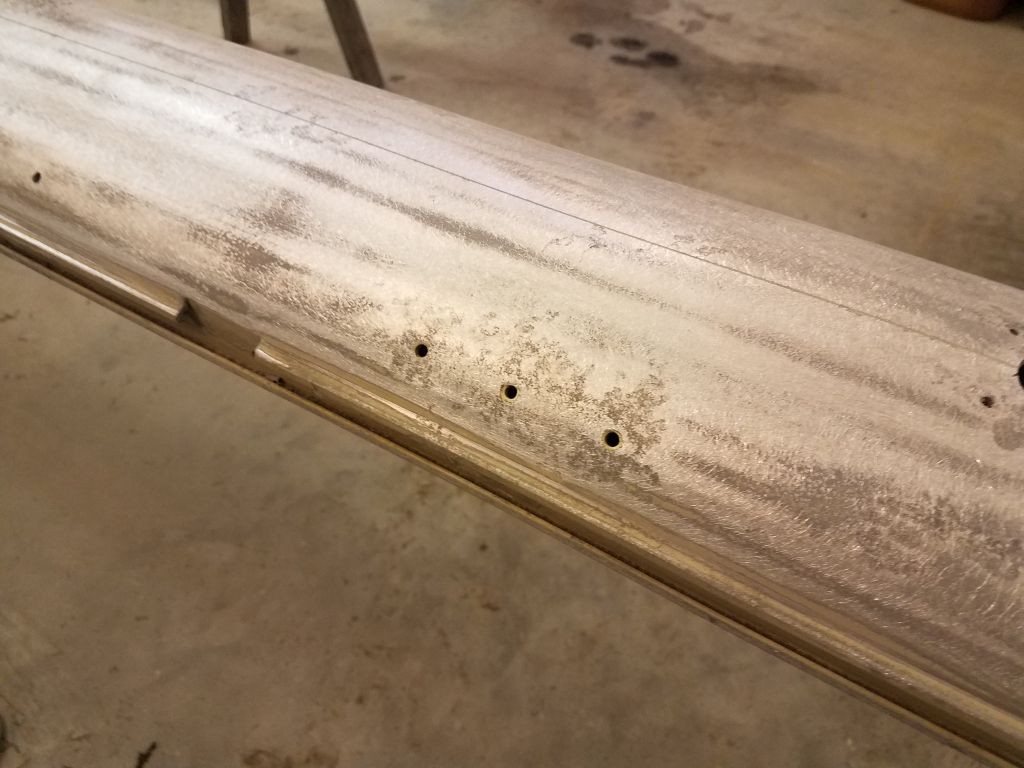
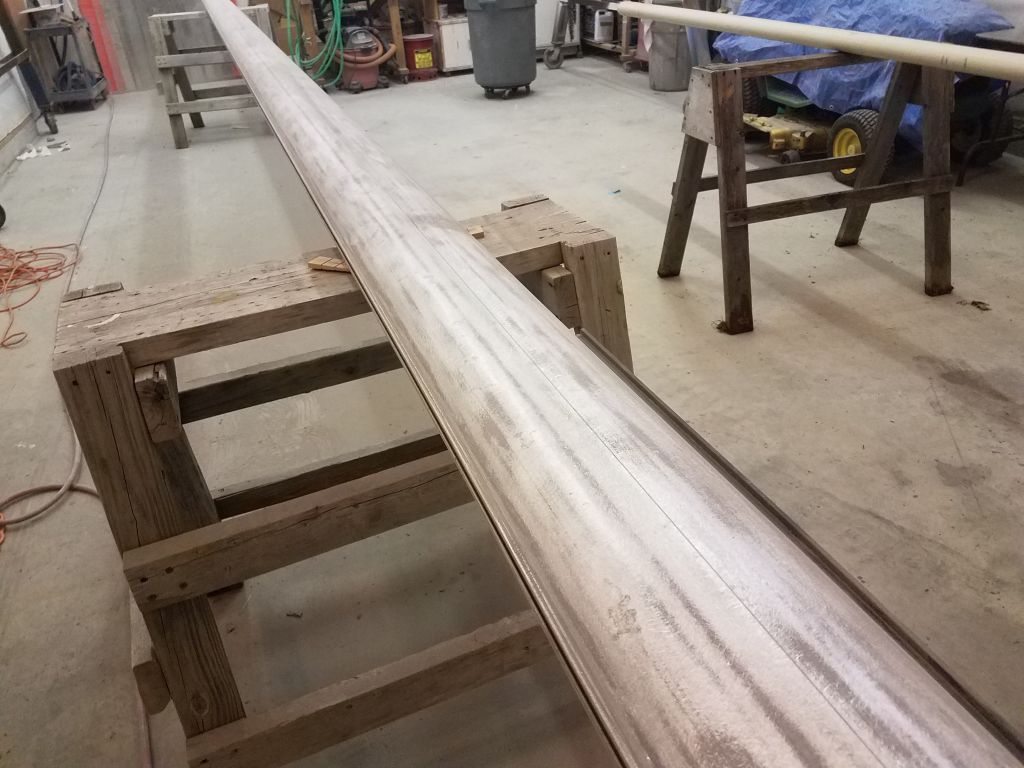
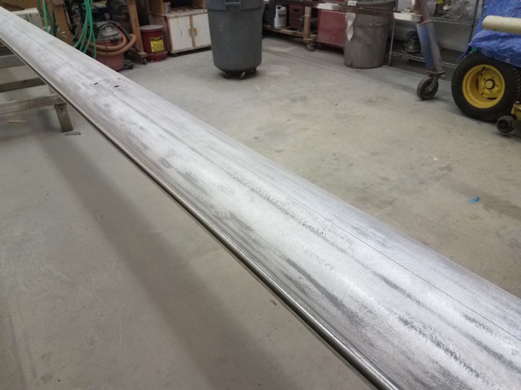
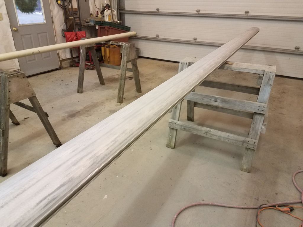
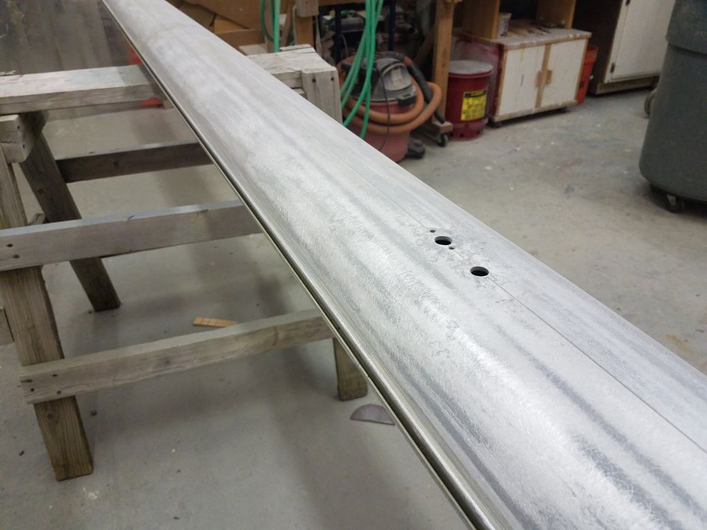
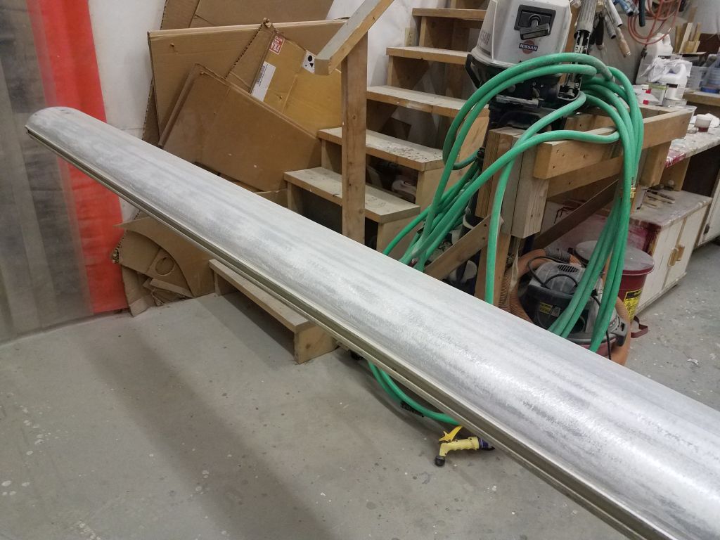
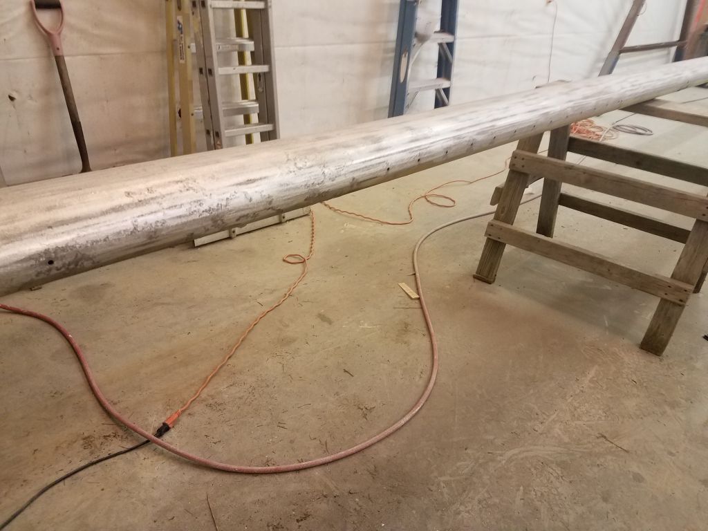
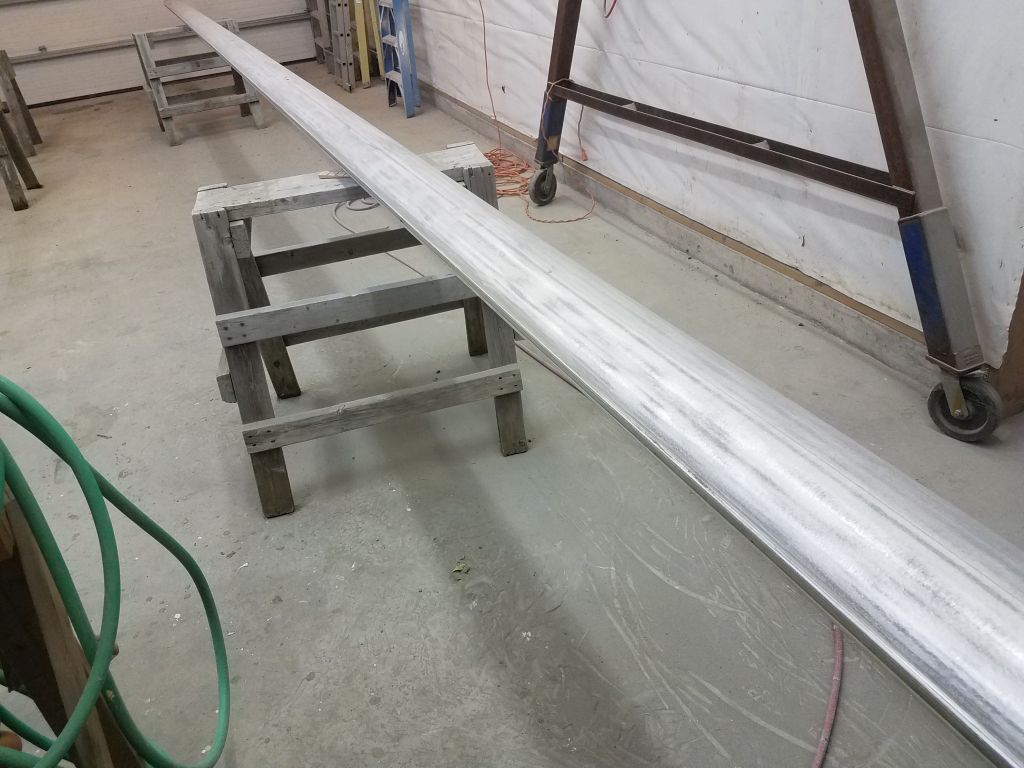
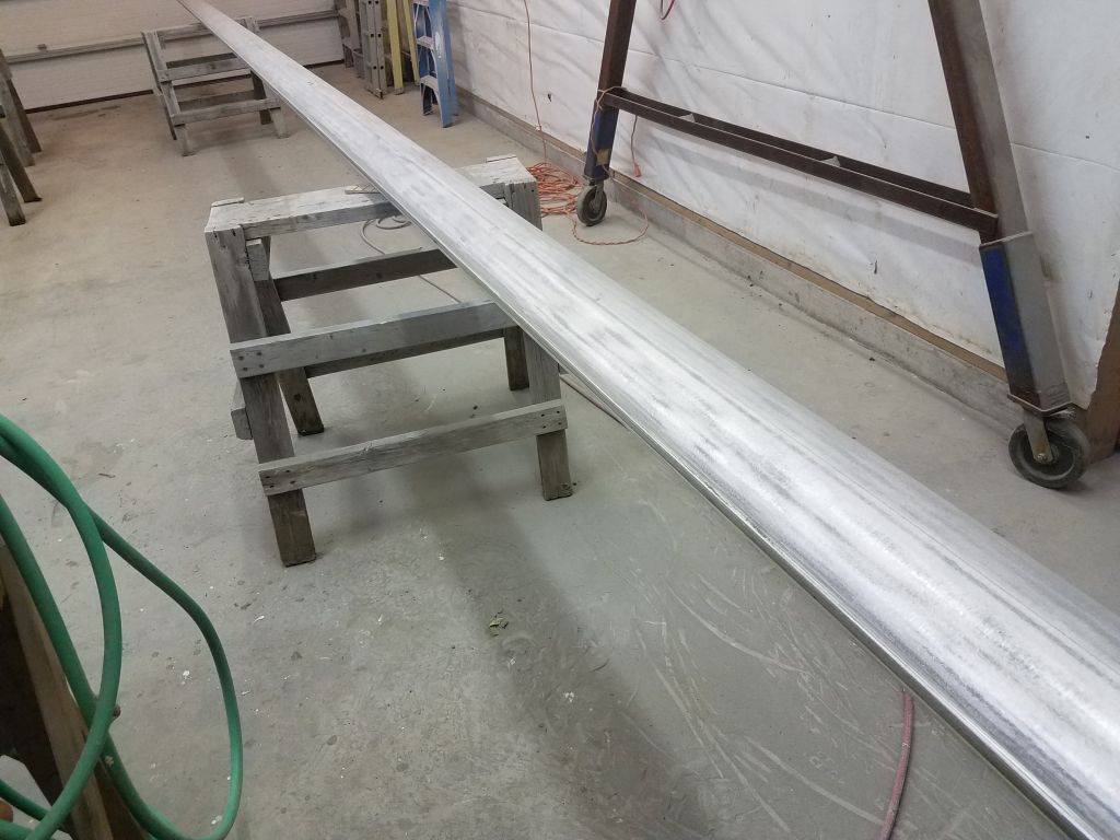
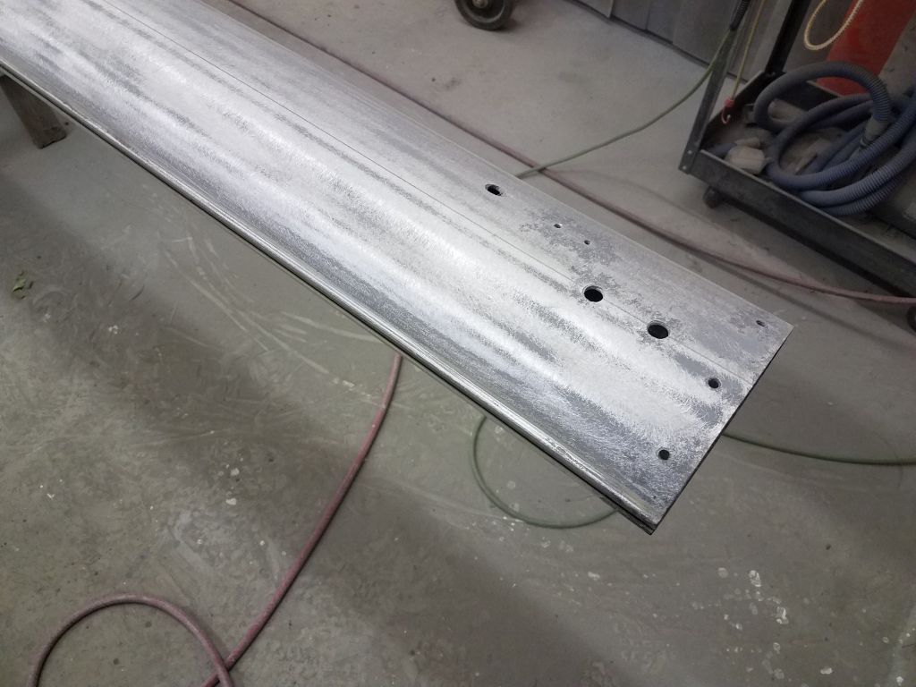
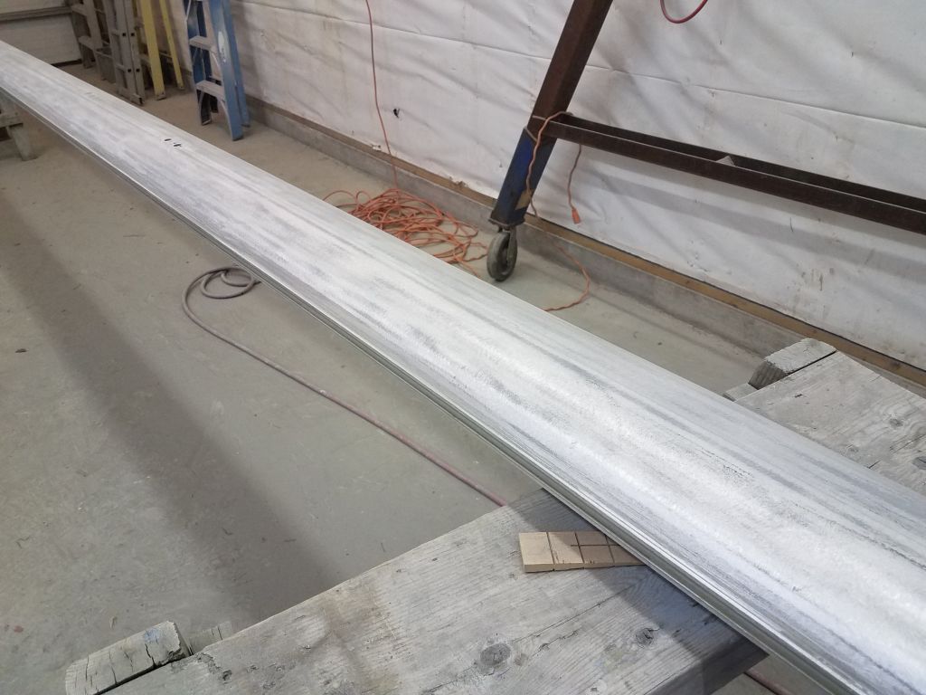
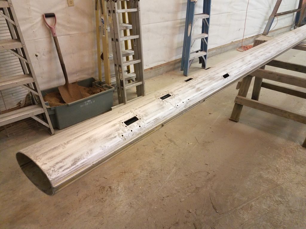
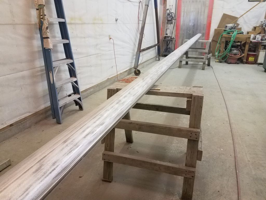
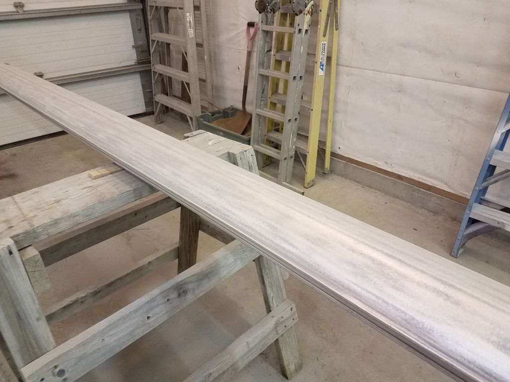
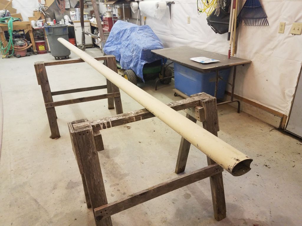
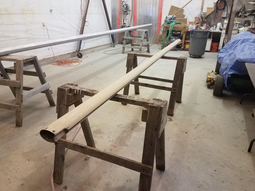
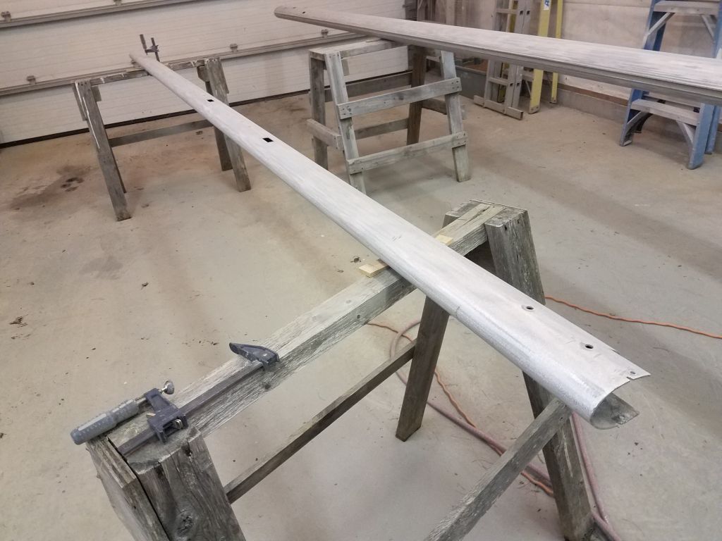
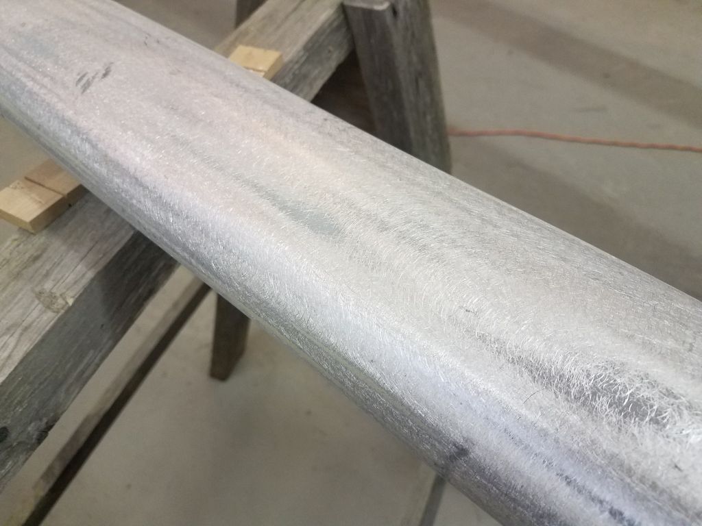
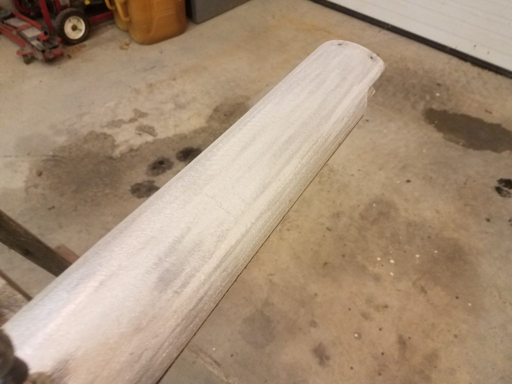
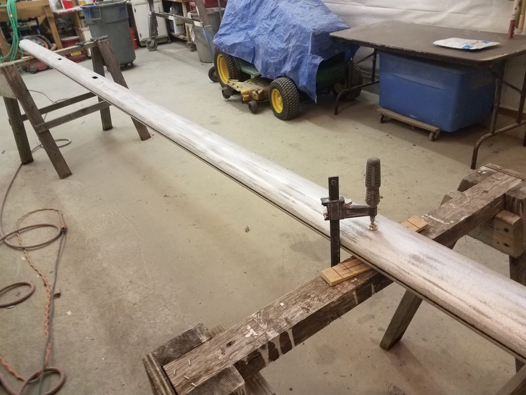
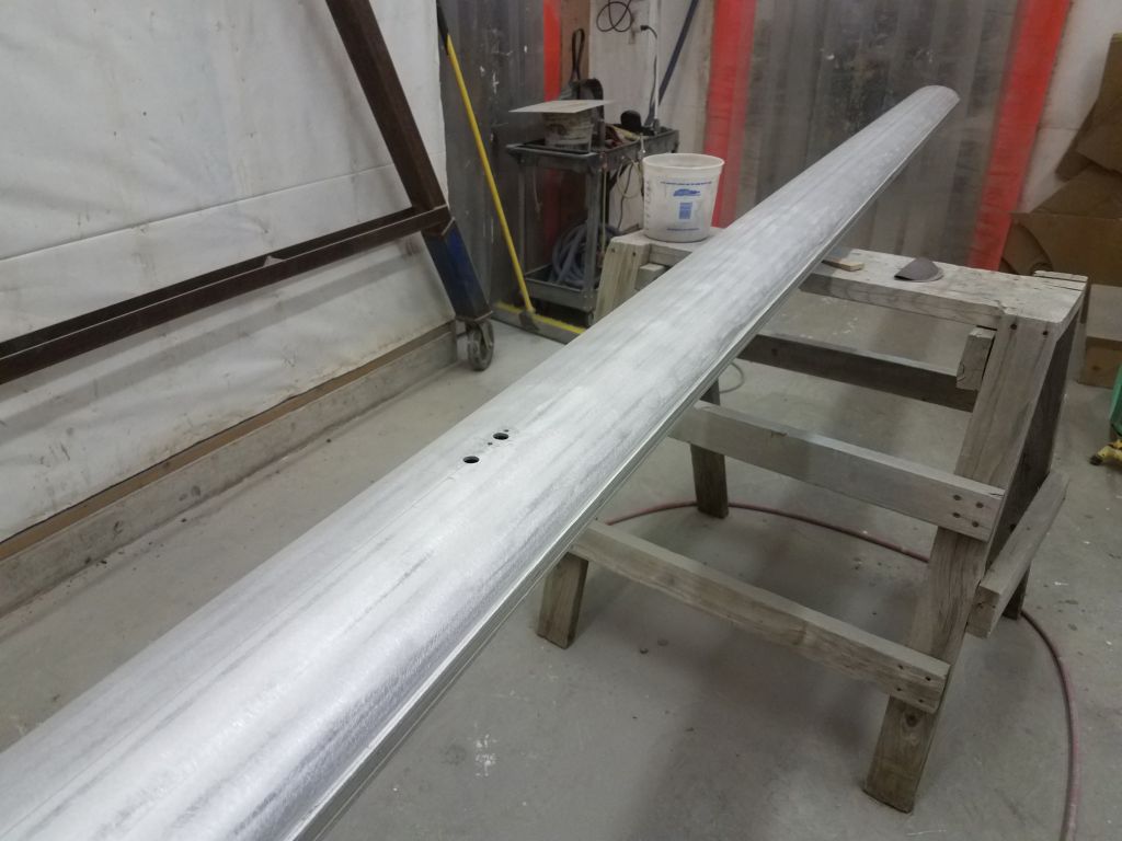
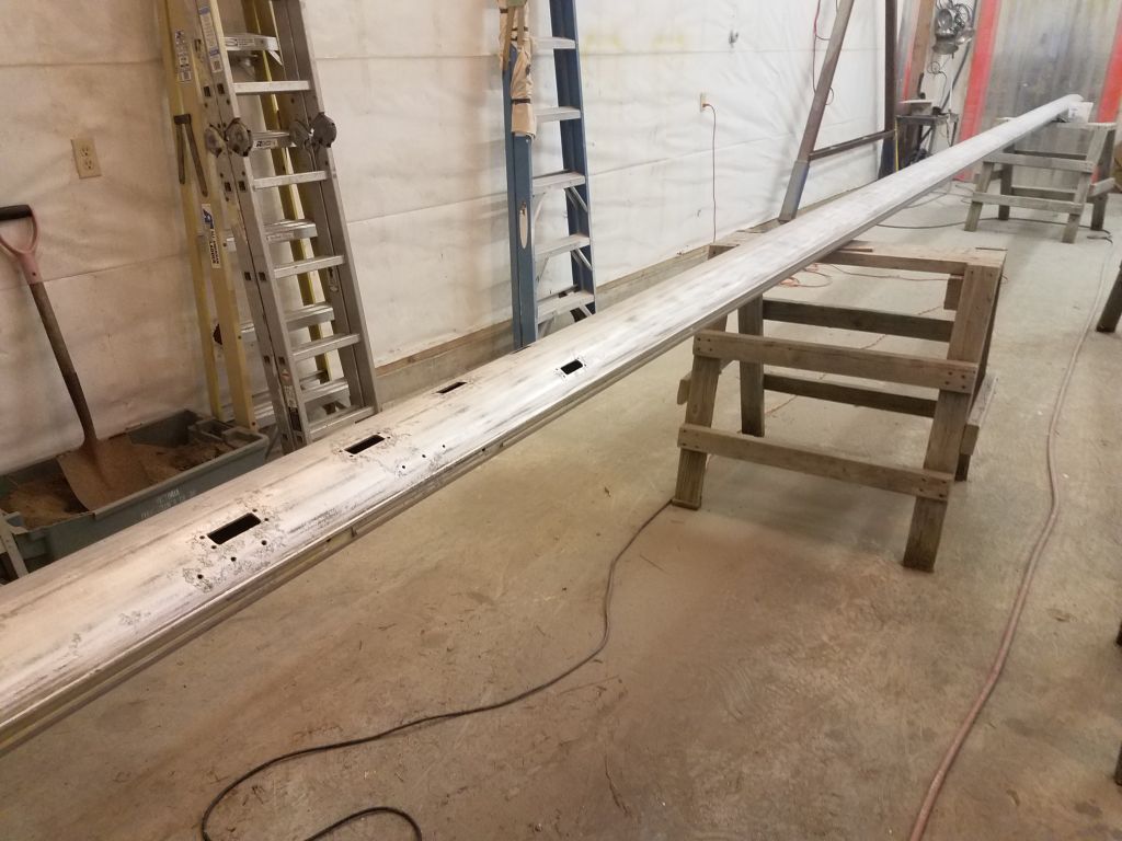
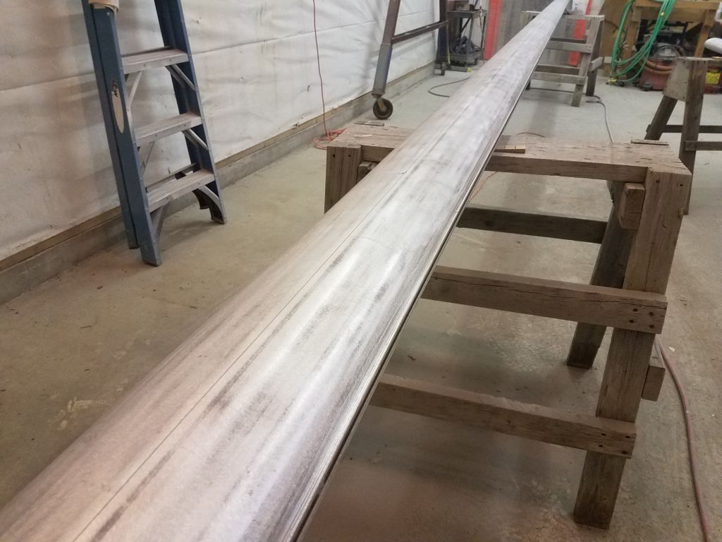
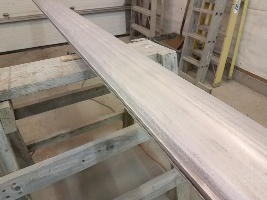
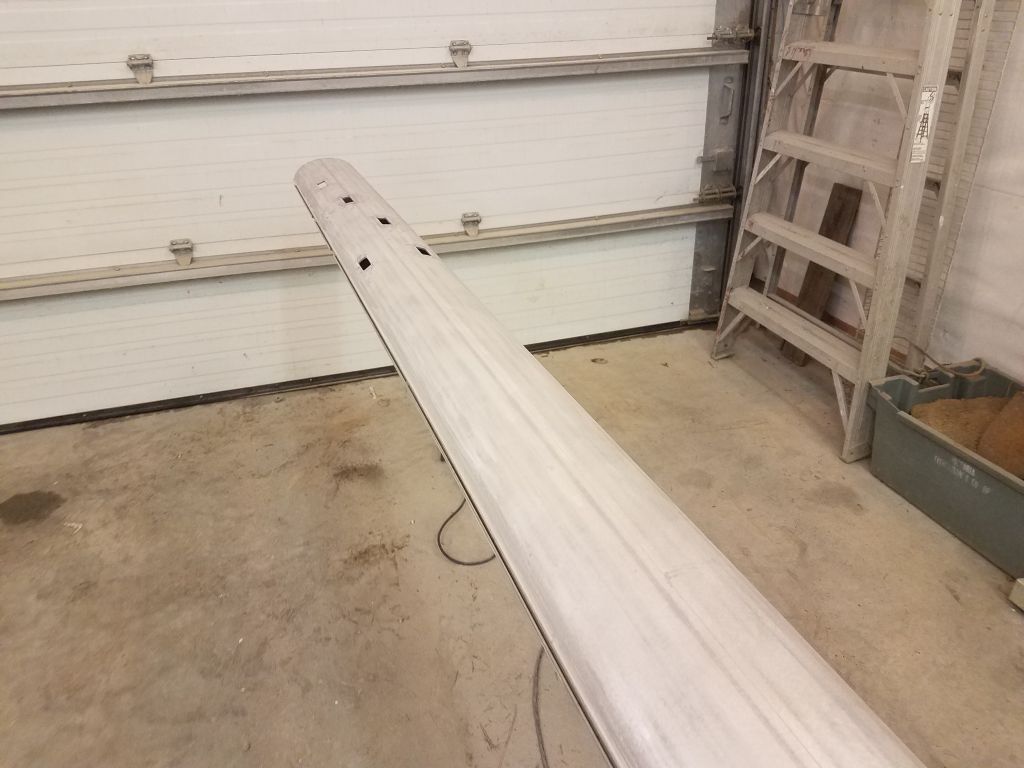
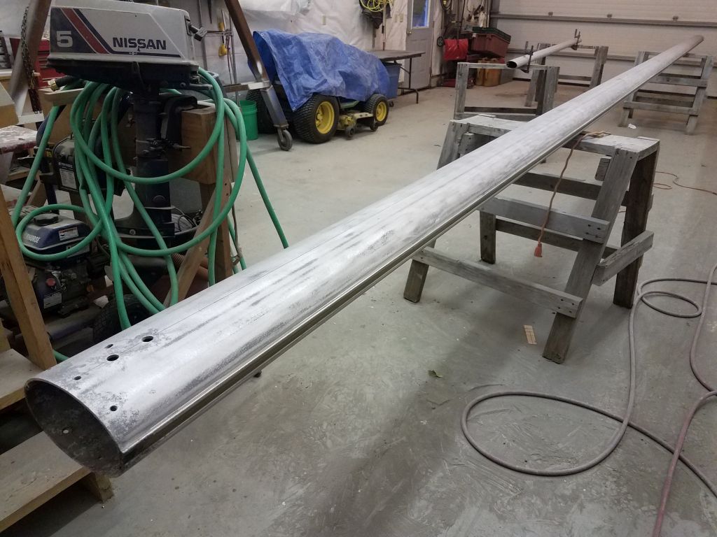
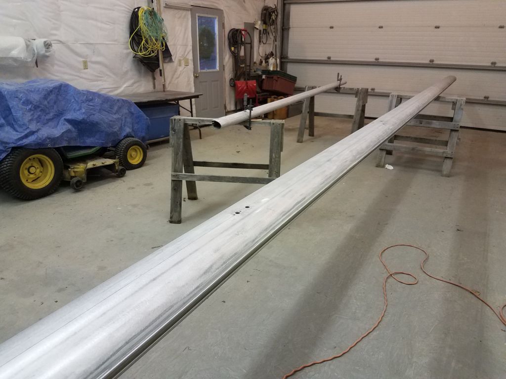
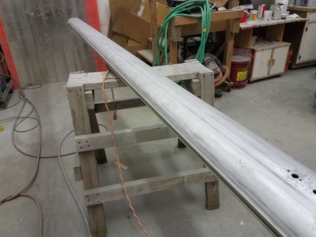
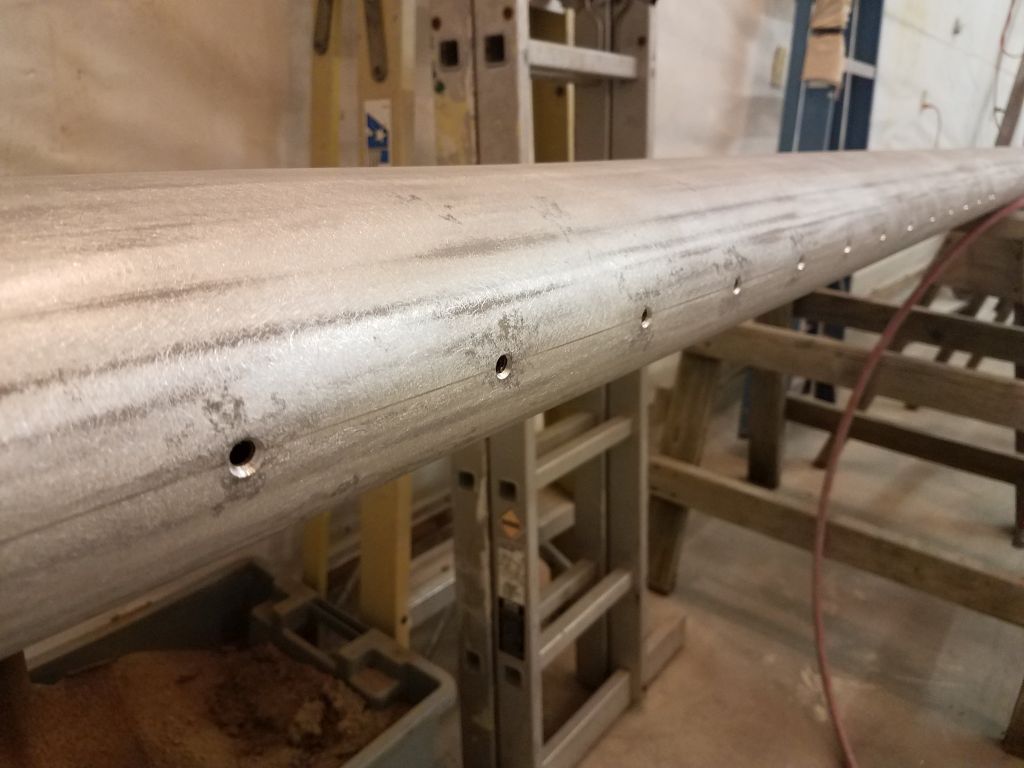
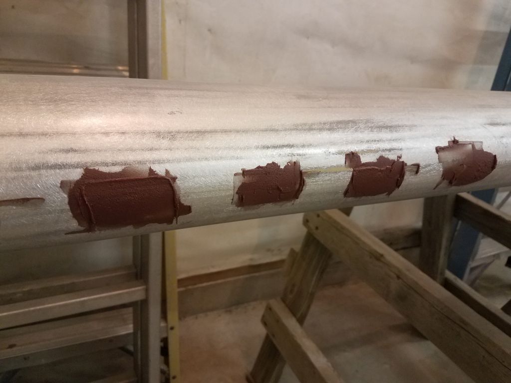
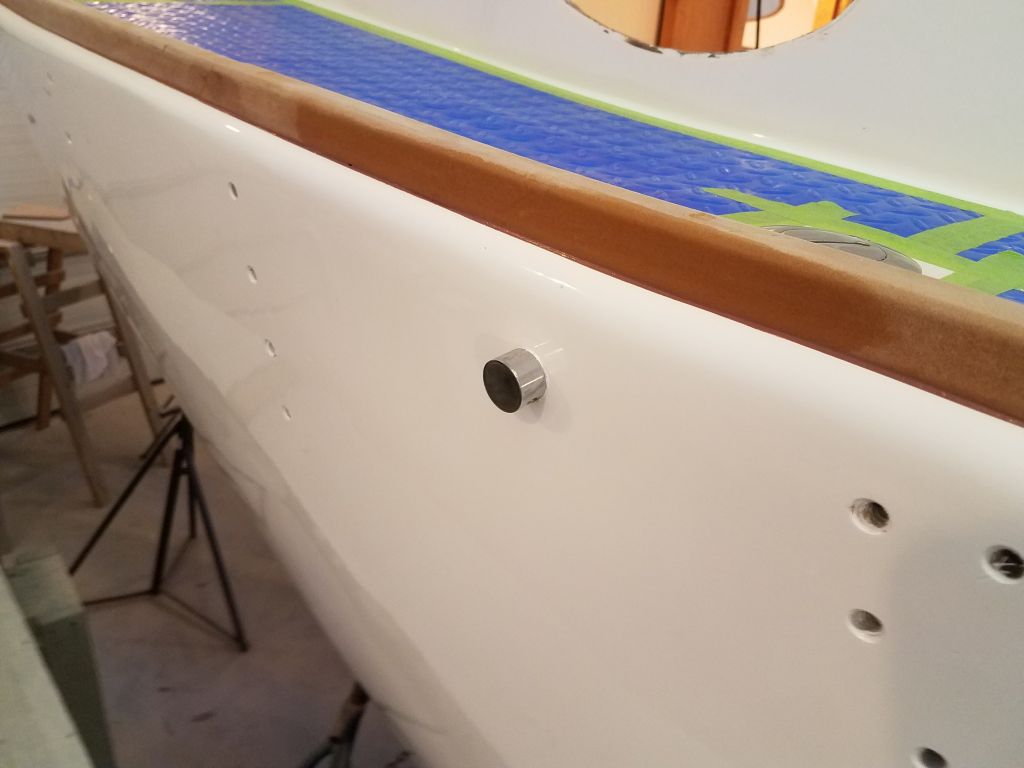
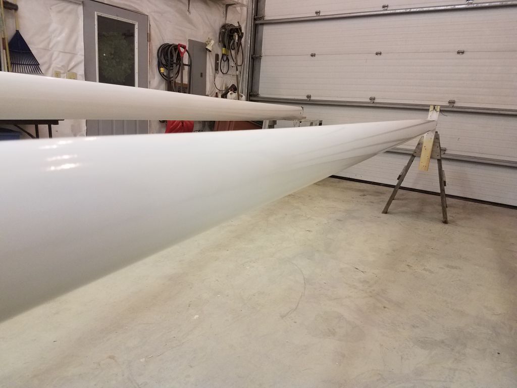
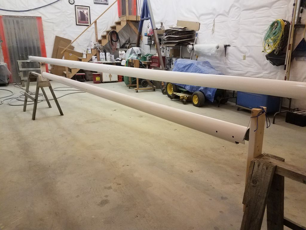
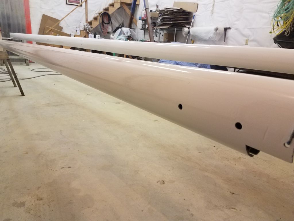
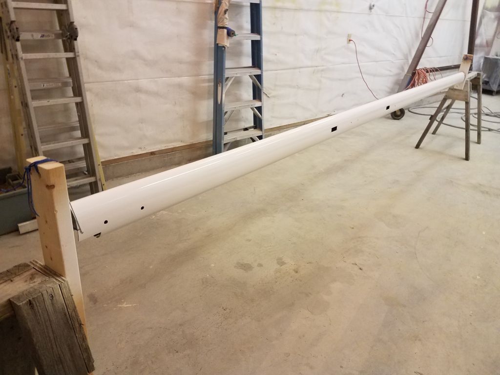
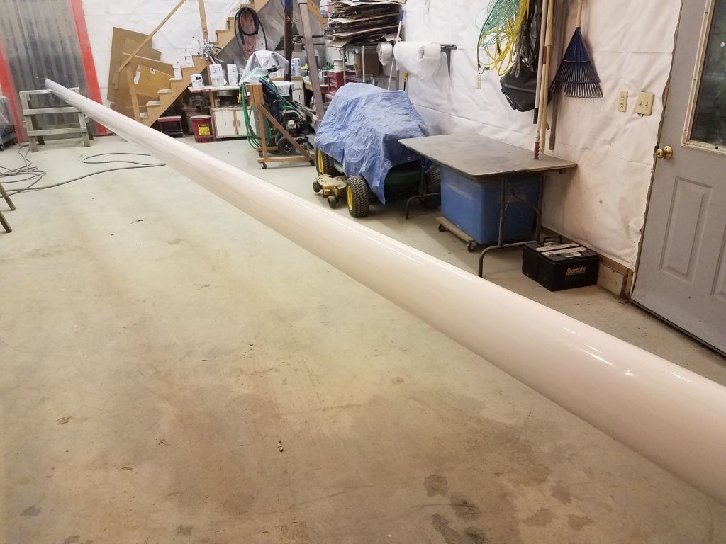
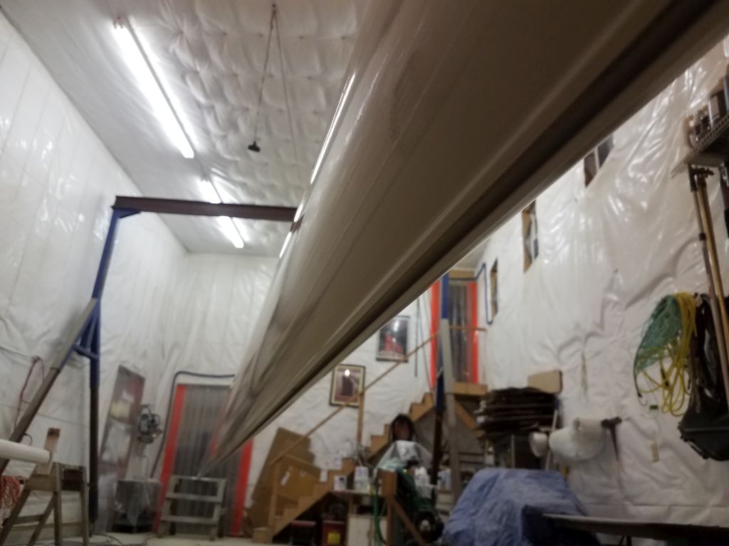
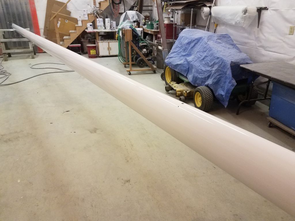
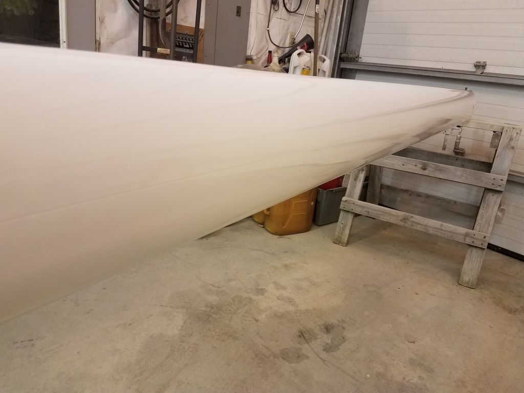
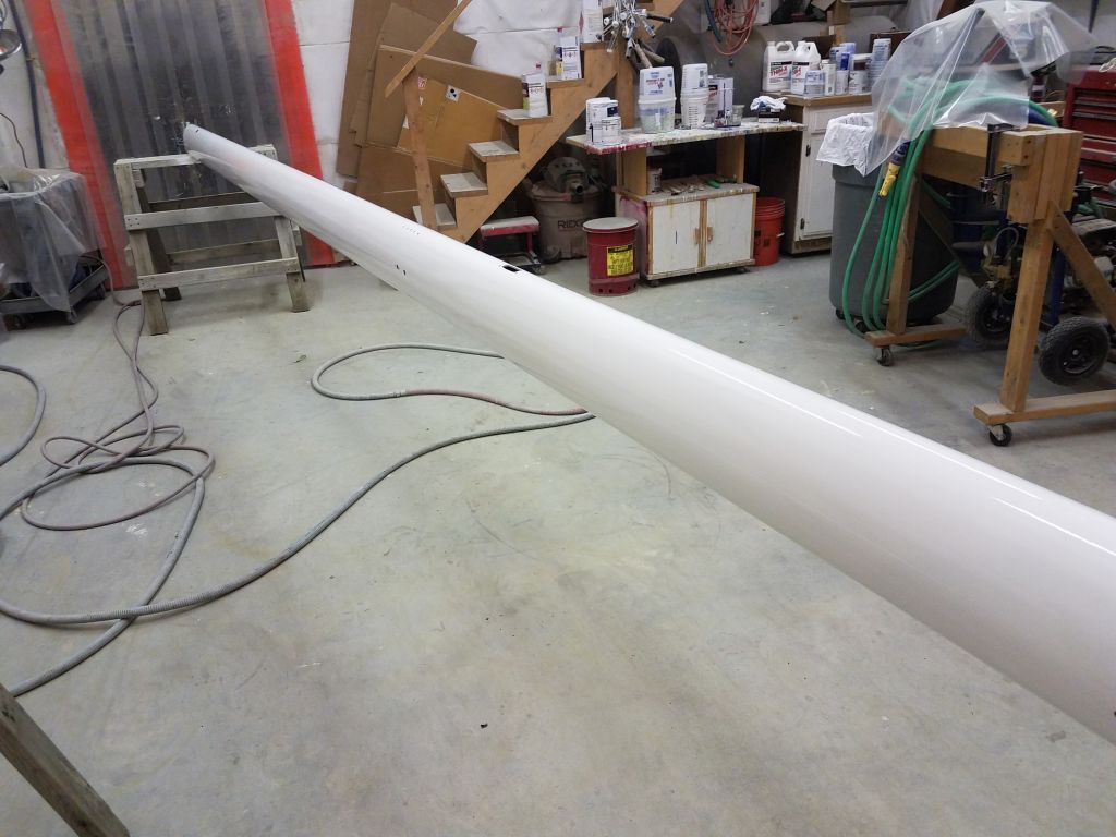
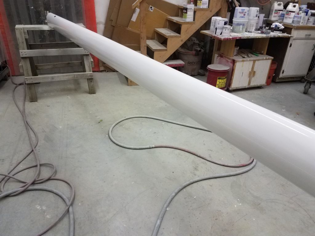
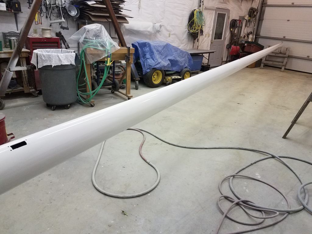
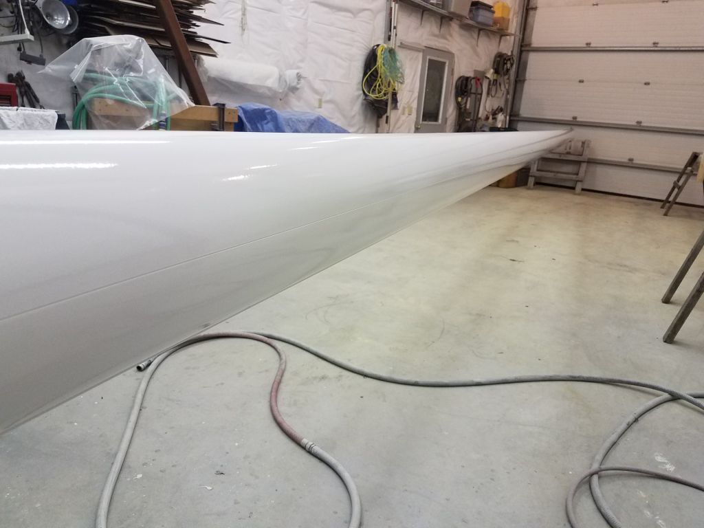
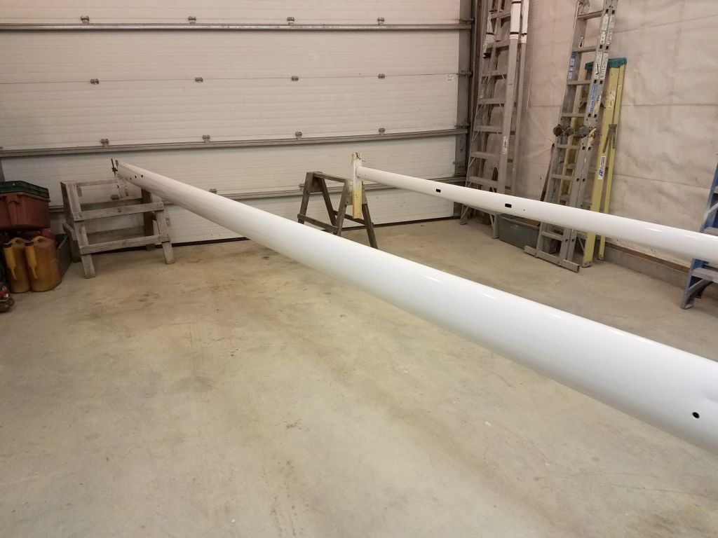
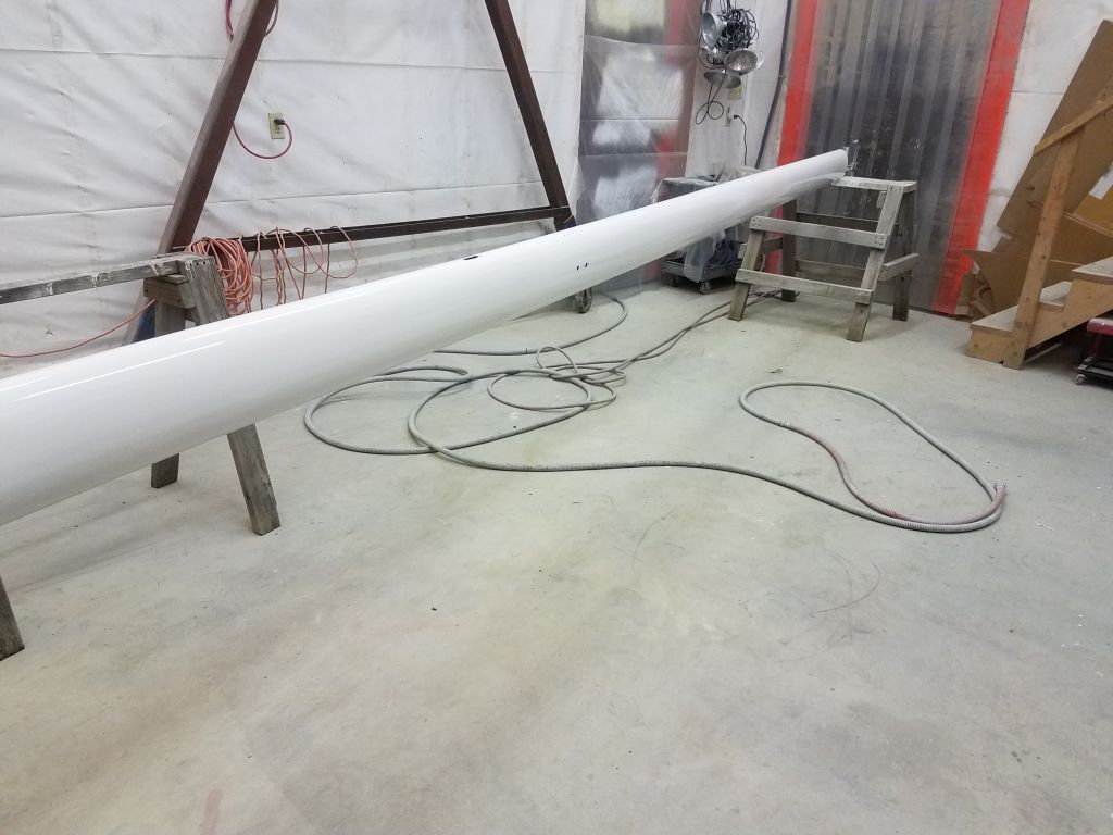
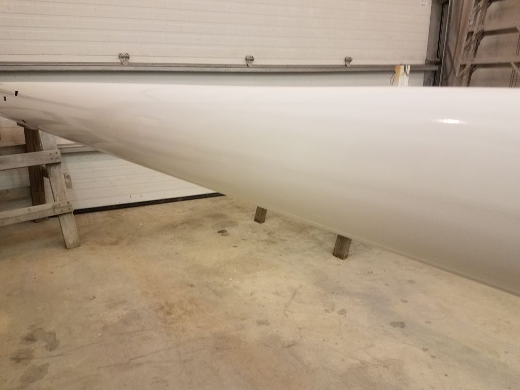
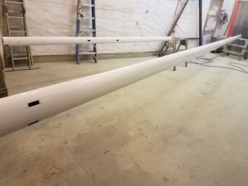
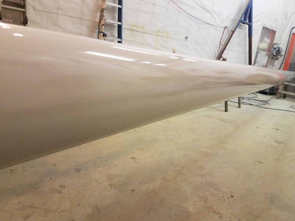
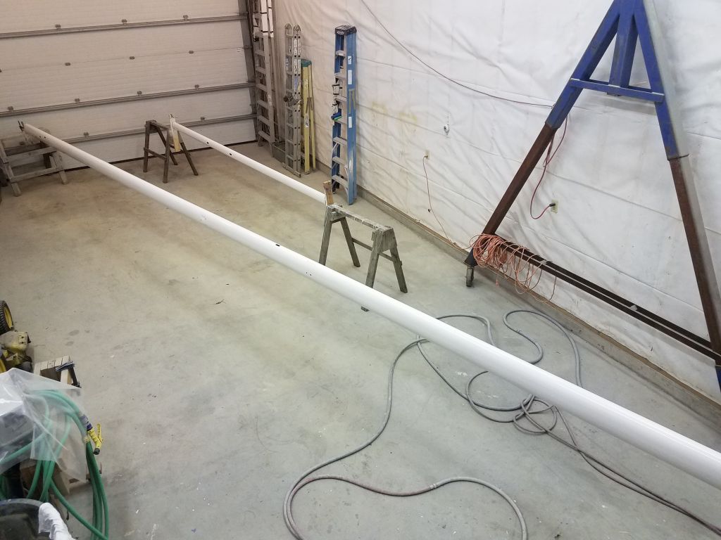
After an early lunch break, I turned to the mast painting for the afternoon. The anti-corrosive metal primer I chose for the spars didn’t require any further primers before topcoat, nor did it require sanding for adhesive purposes (within the specified time frame, which was six months after application). The surface as applied was smooth and without obvious flaws, but I went over the spars briefly with a Scotch-Brite pad just to knock down any minor surface texture. After solvent-washing and other final preparations, I spray-applied three coats of the Alexseal snow white gloss topcoat I used elsewhere on the boat, leaving the new coating to cure overnight.


Total time billed on this job today: 6.5 hours
0600 Weather Observation: 20°, mostly clear. Forecast for the day: Partly sunny, 37°