Wednesday
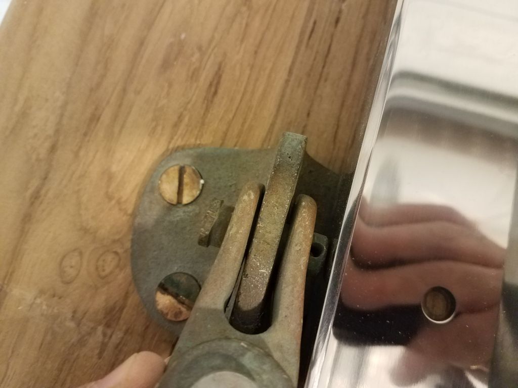
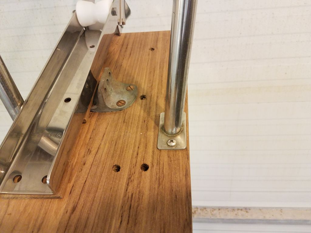
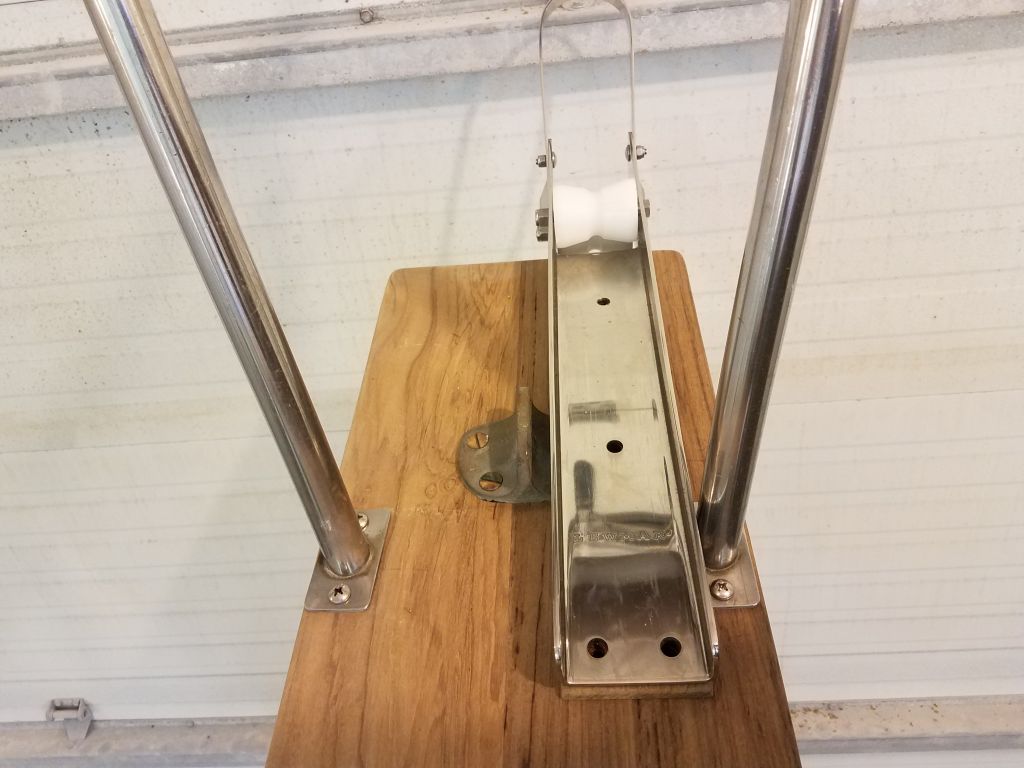
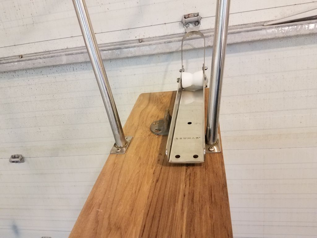
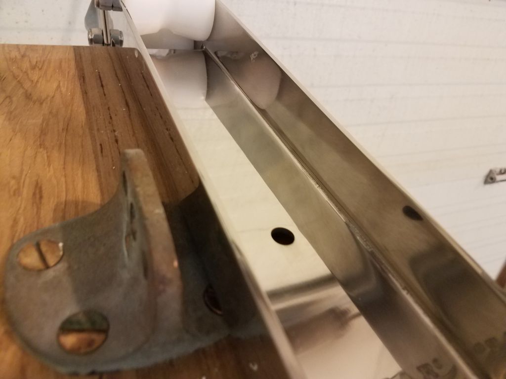
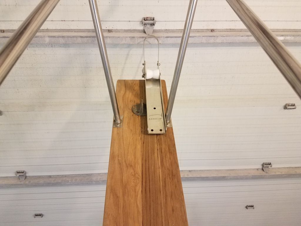
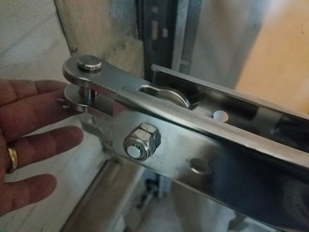
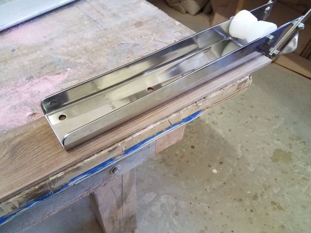
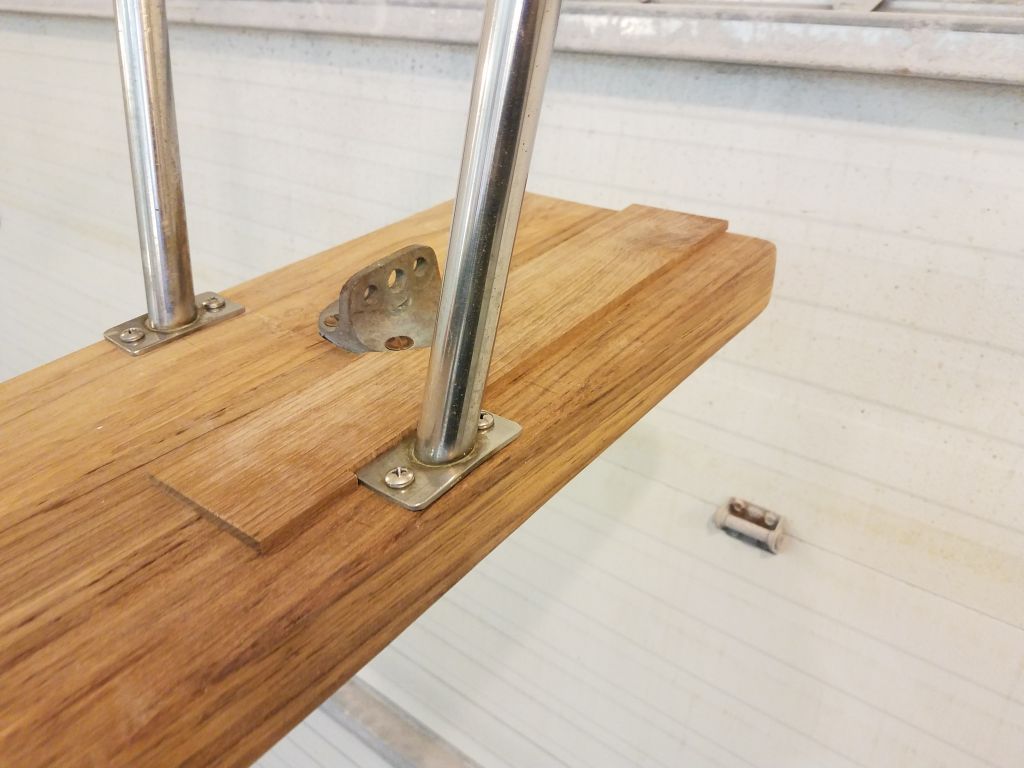
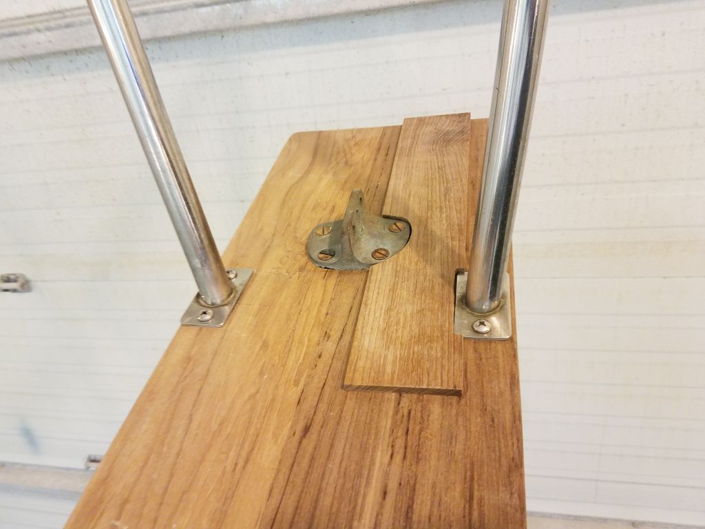
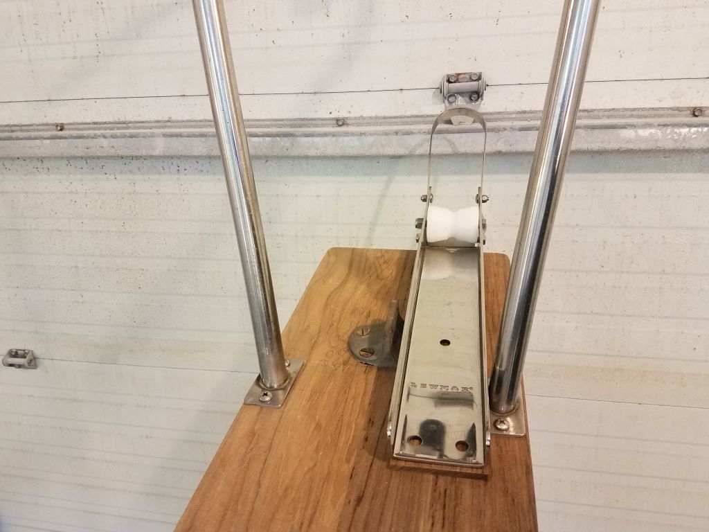
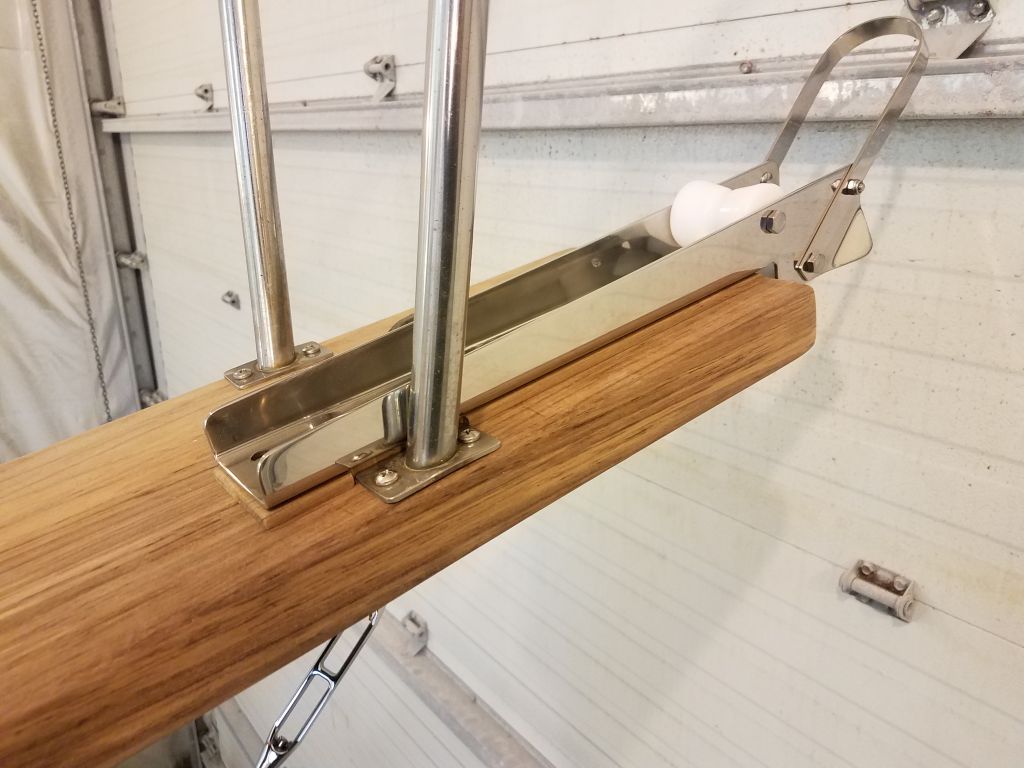
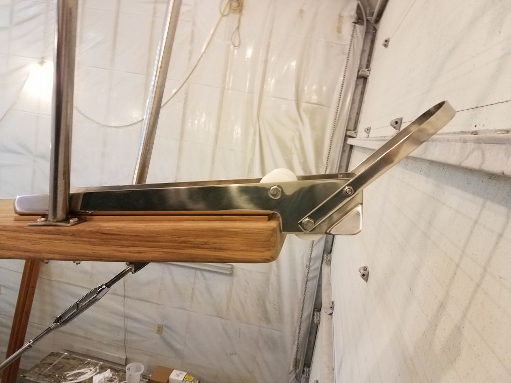
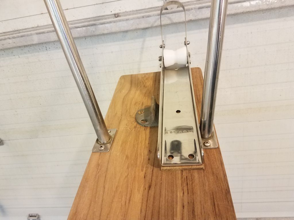
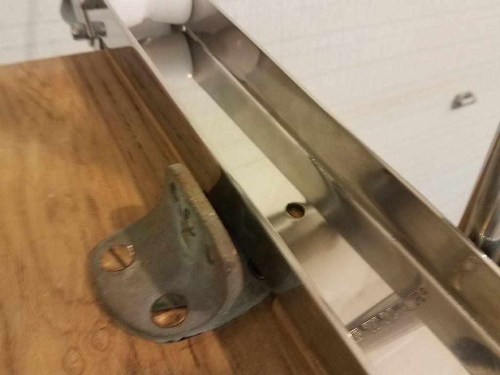
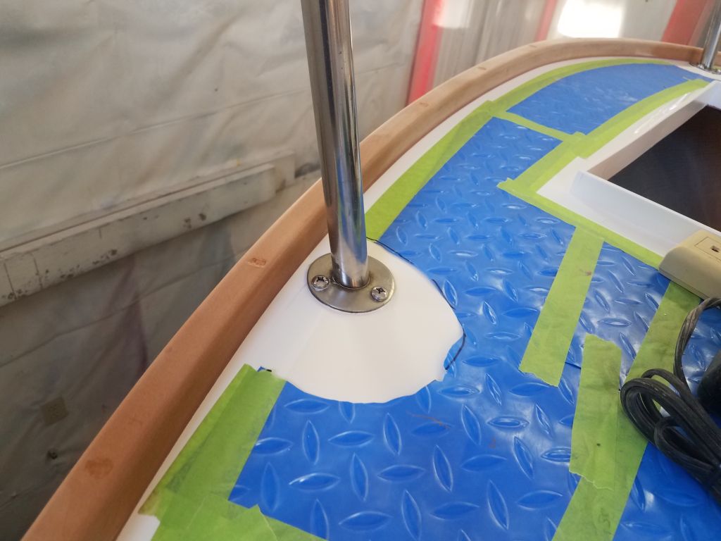
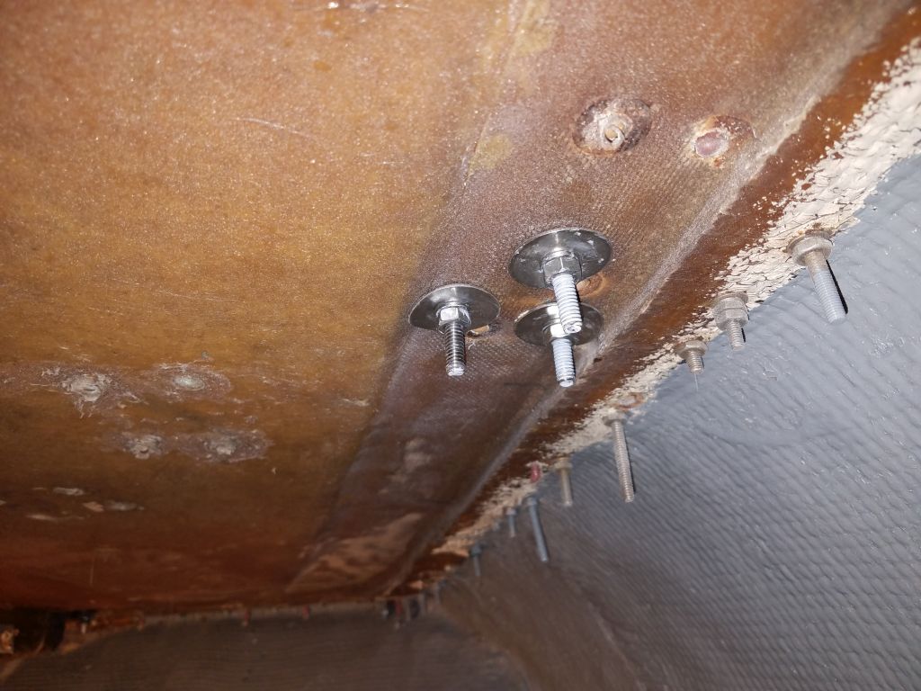
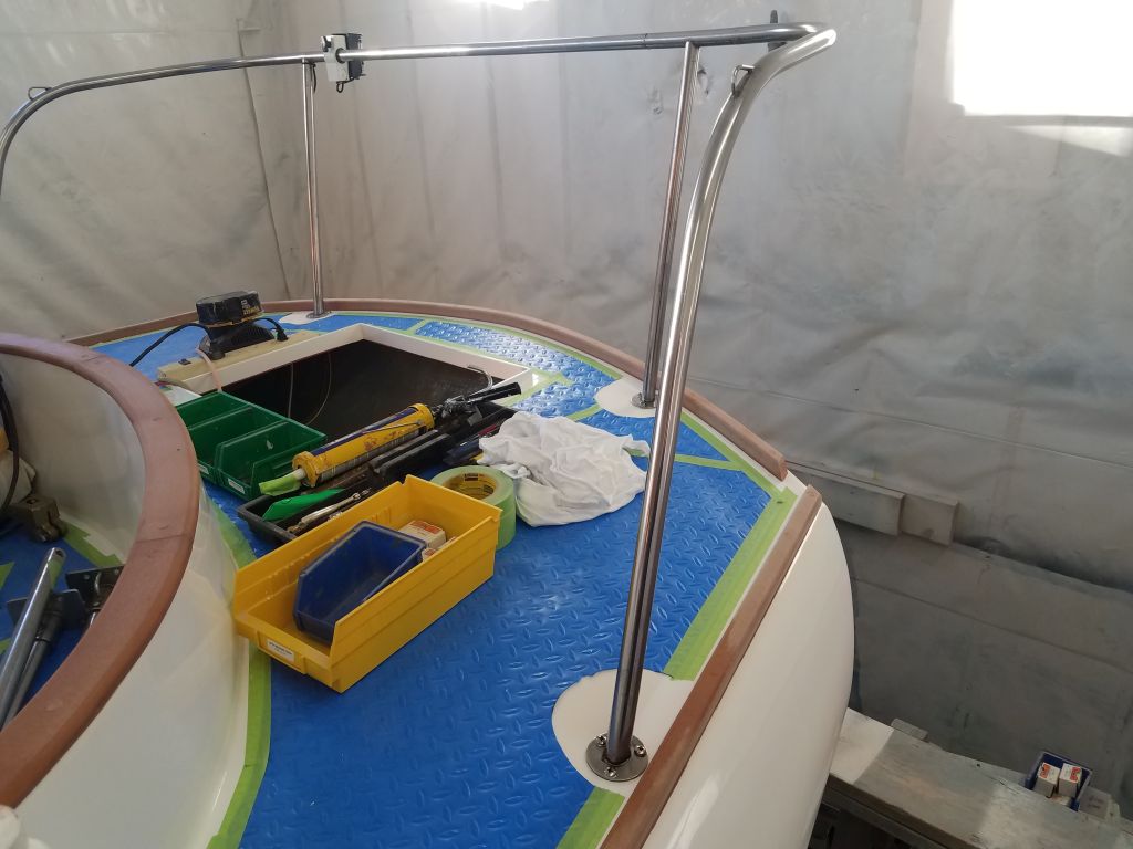
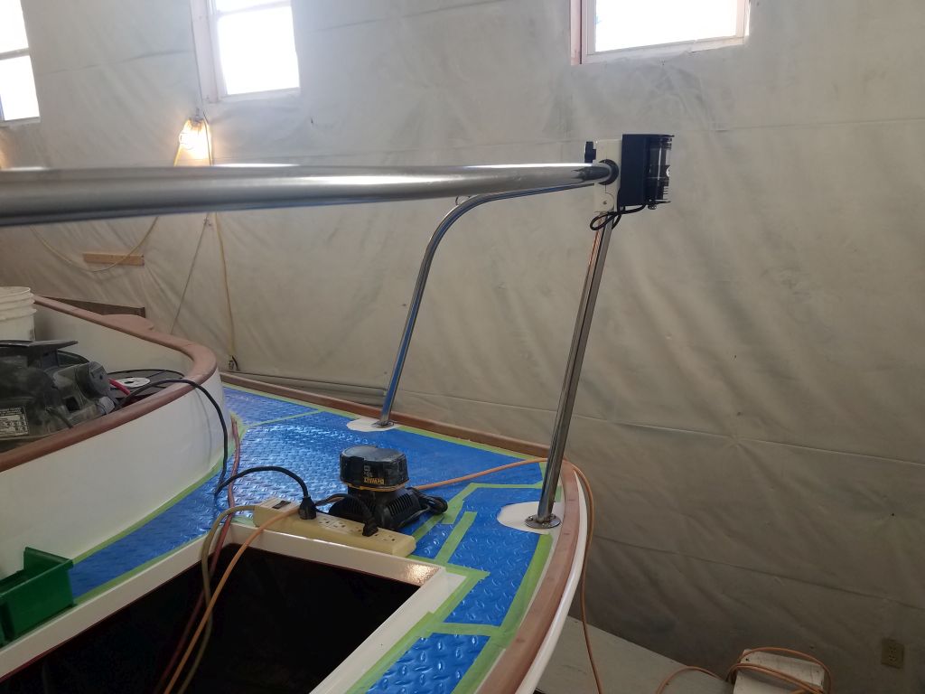
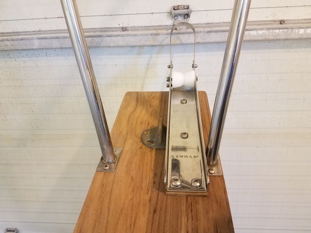
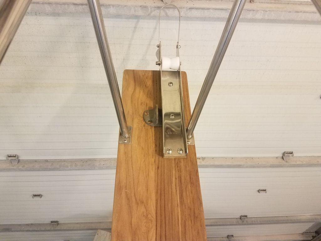
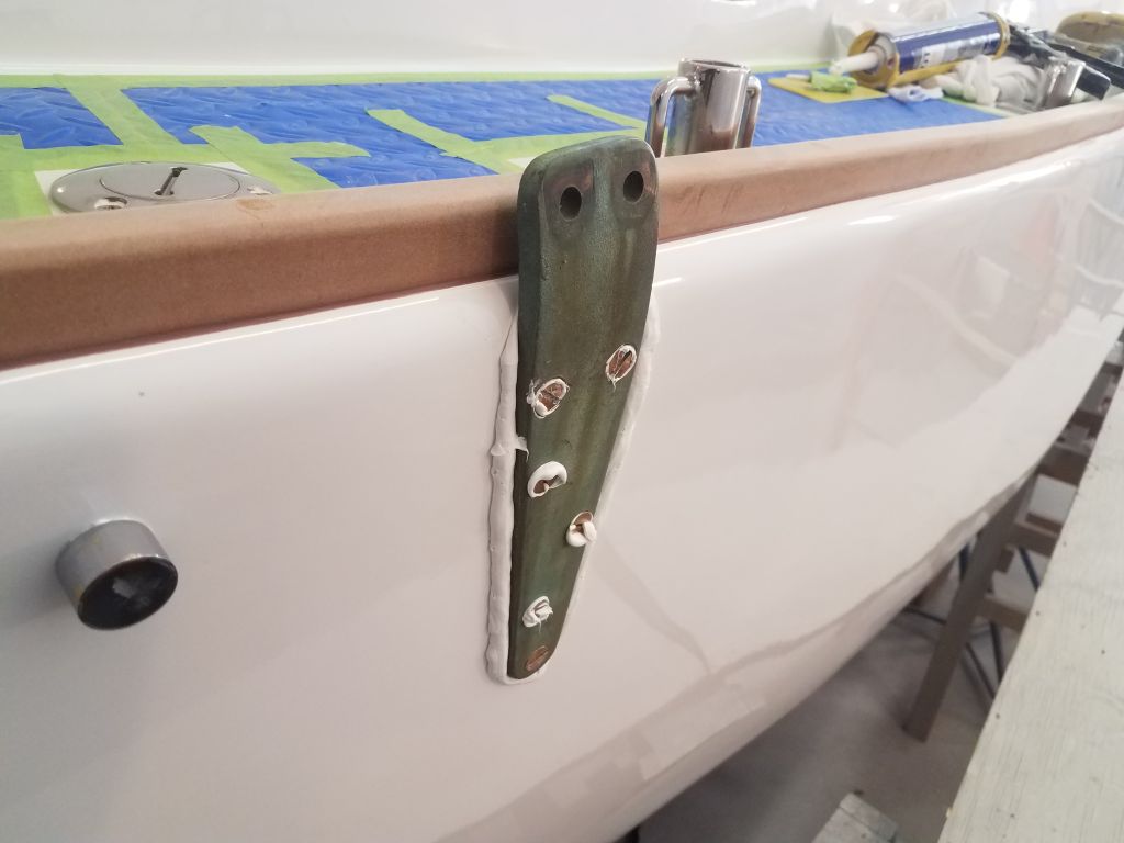
With new fasteners on hand, I finished up the anchor roller installation.


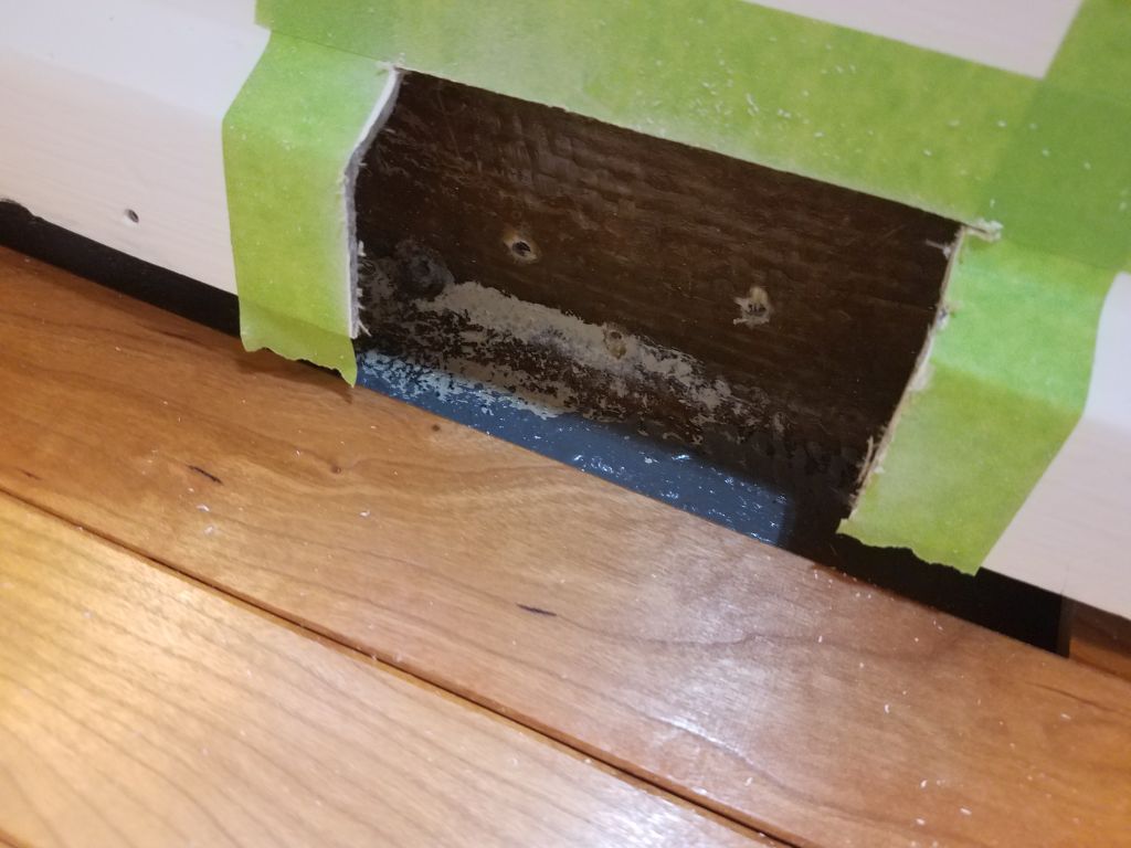
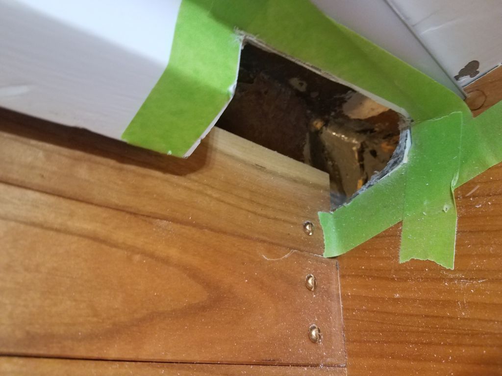
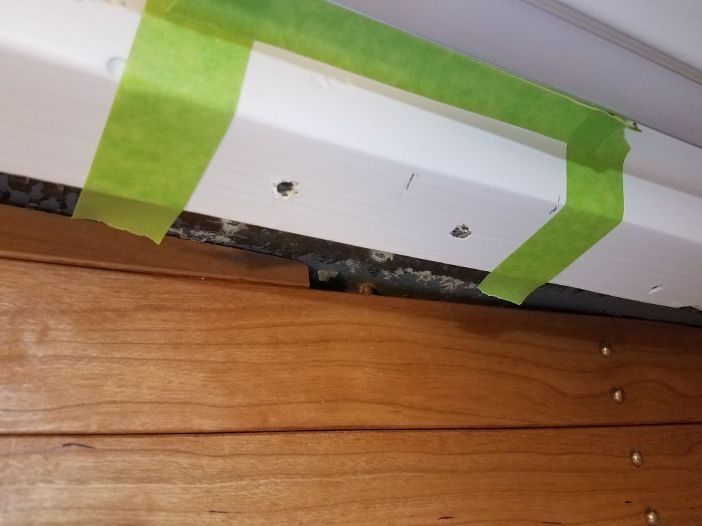
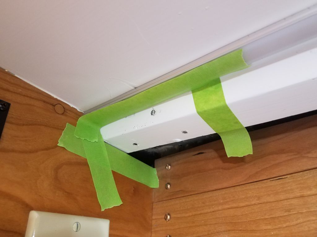
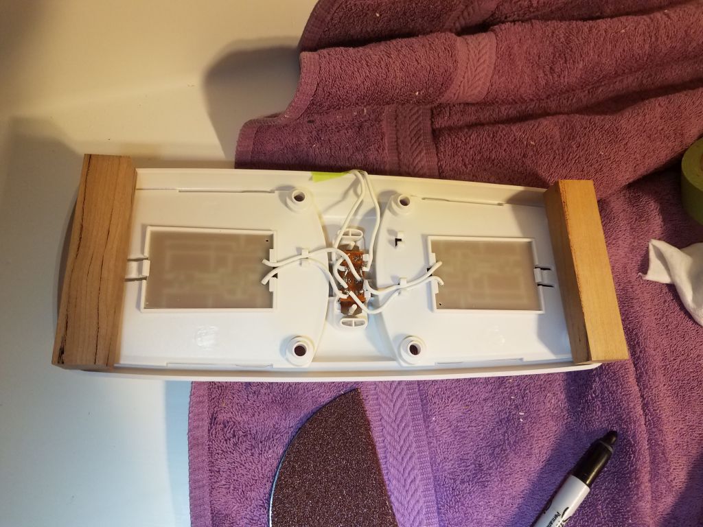
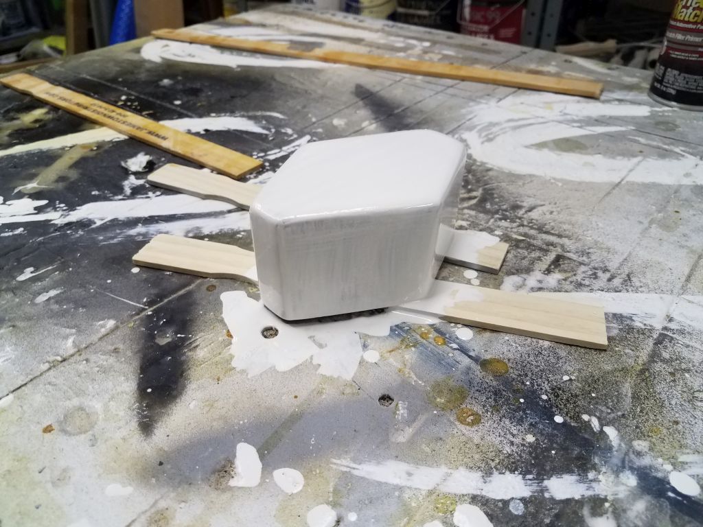
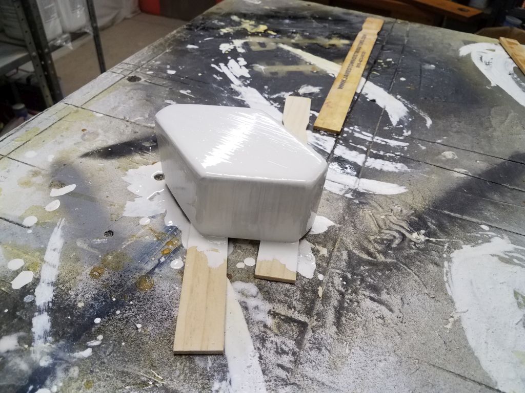
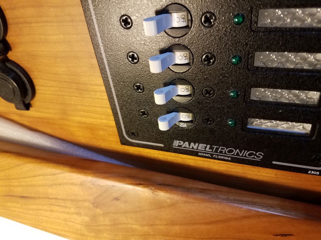
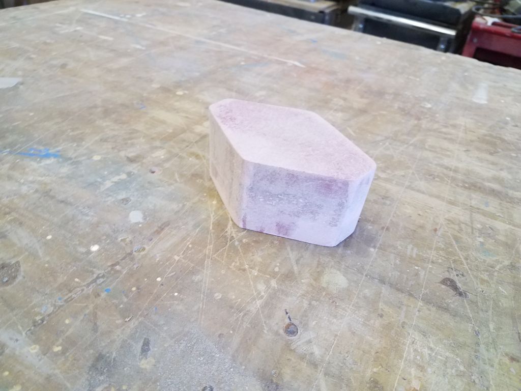
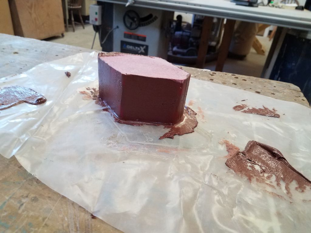
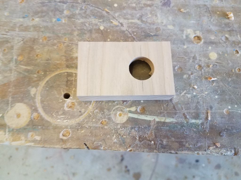
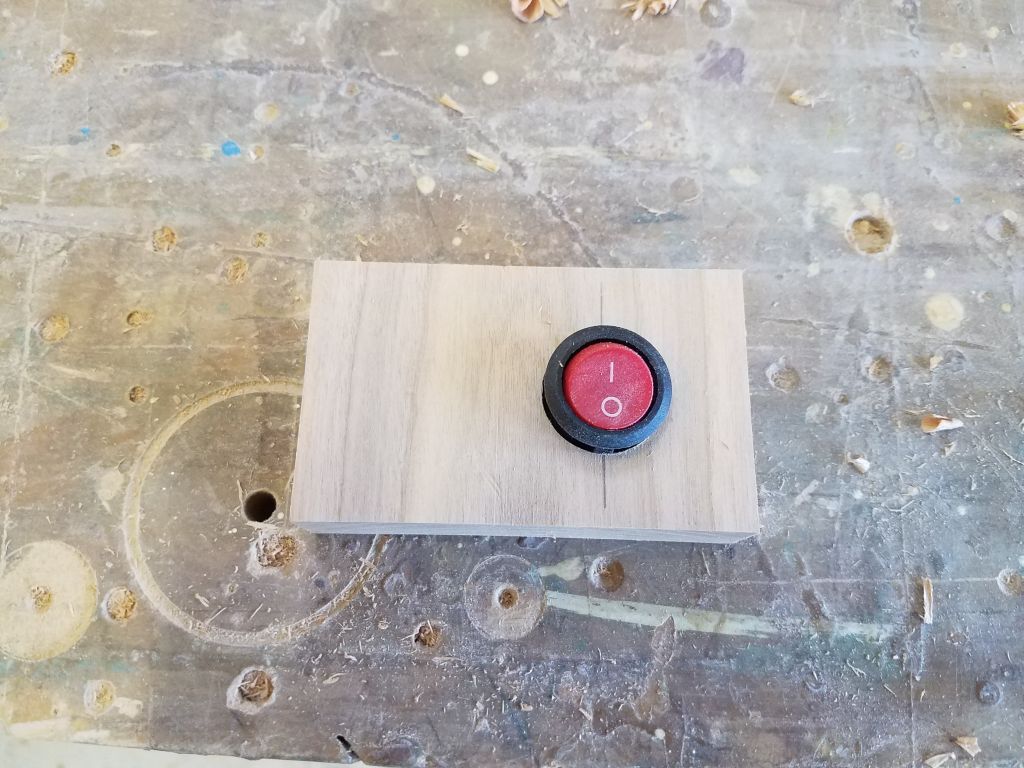
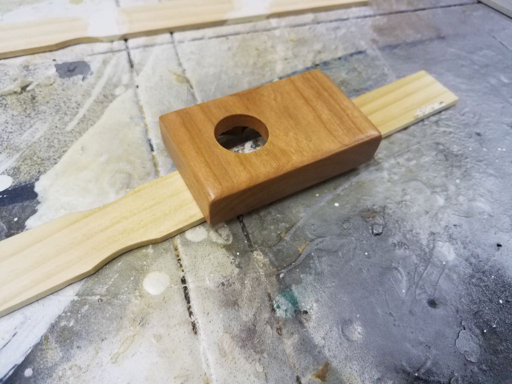
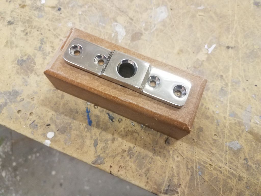
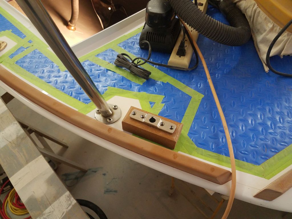
In order to install the light switch that would operate the galley and companionway lights from near the companionway itself, I needed to build a small wooden base into which the switch could fit, and which would also provide a bit of space for wiring, since the mounting location on the bulkhead had various clearance and access issues that limited the mounting options. From a piece of cherry, I milled a small block for the job, removing material from the back side to make room for wiring, then drilling a hole that would later accept the small switch itself. I sanded the block and rounded its edges, then began the varnish process so I could finish up that installation and small bit of wiring soon.

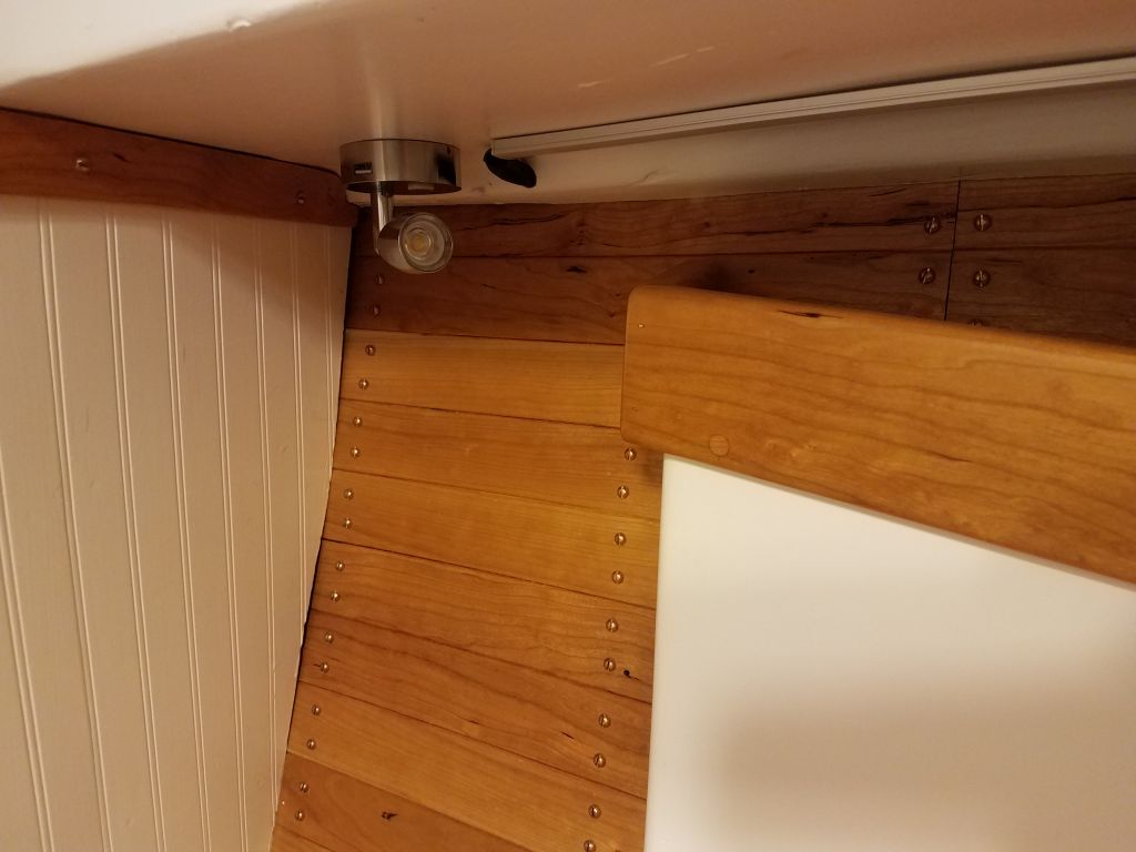
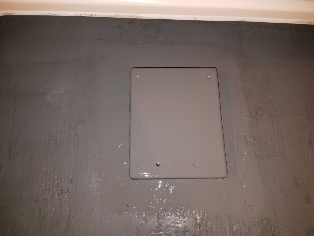
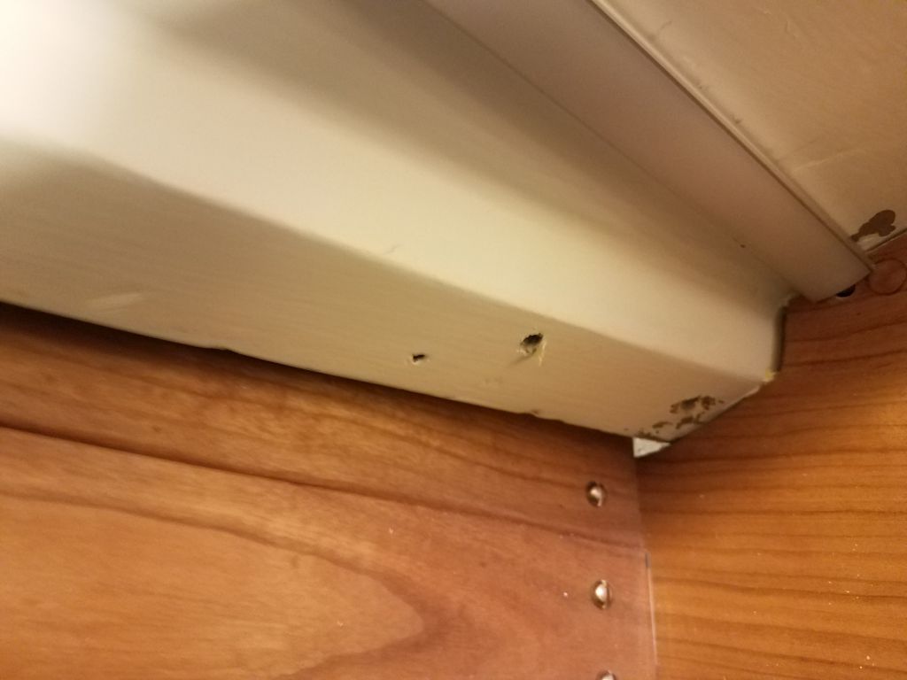
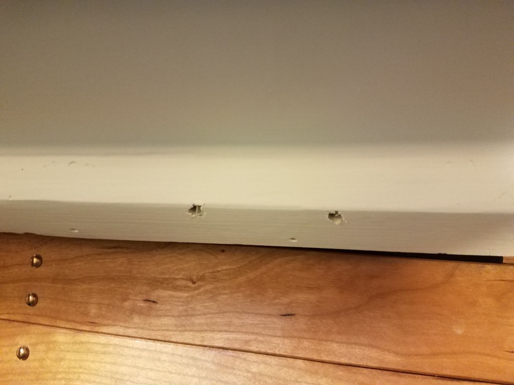
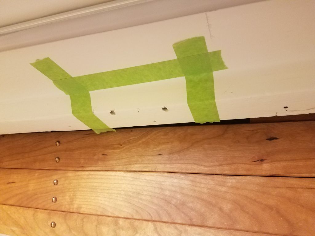
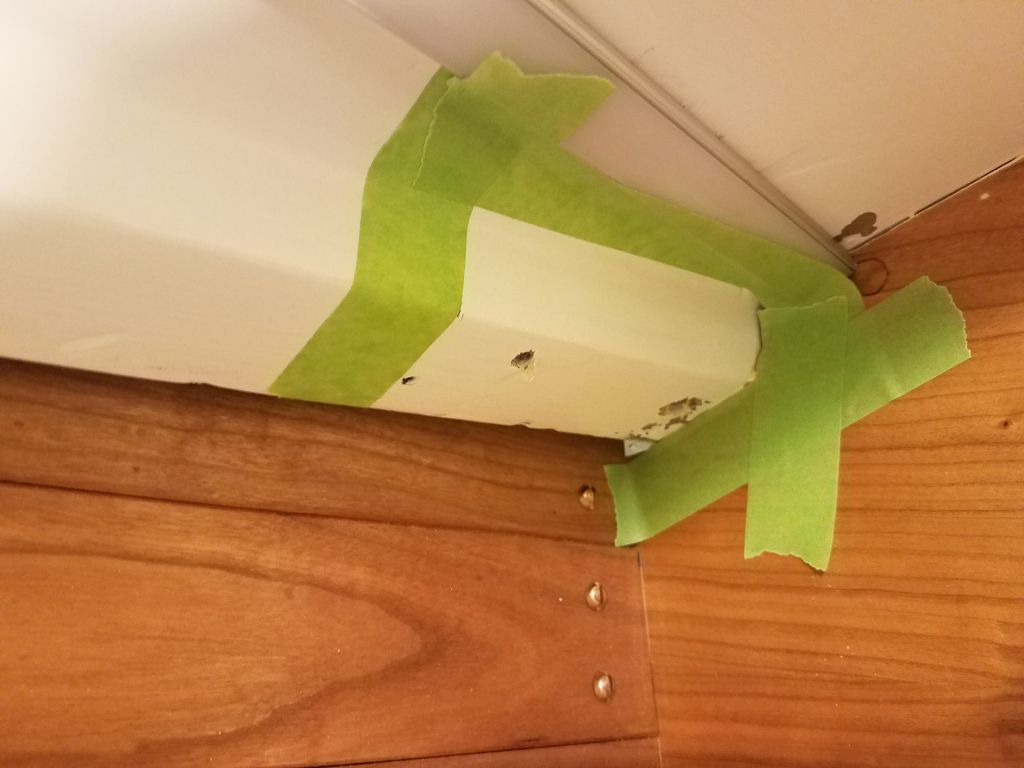
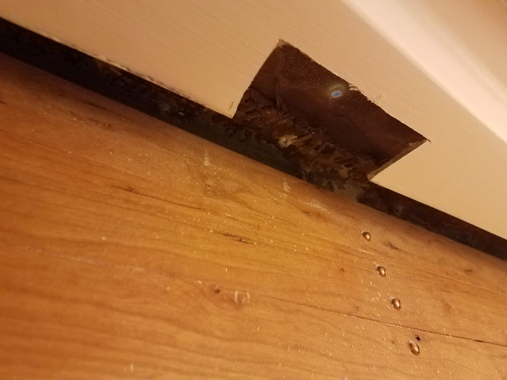
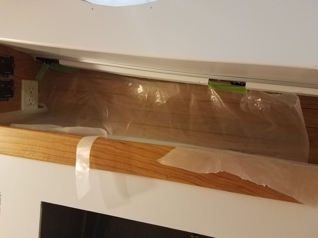
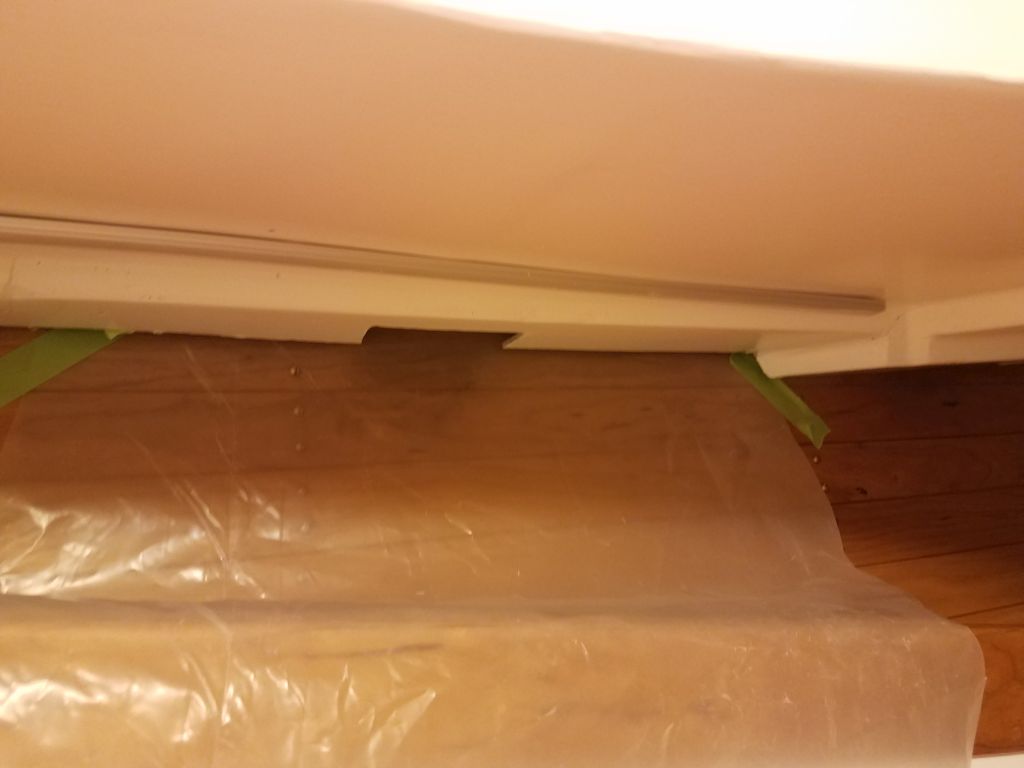
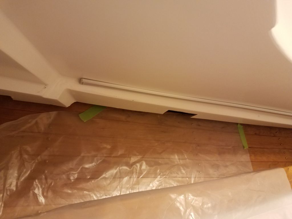
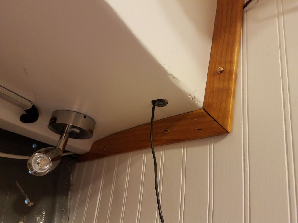
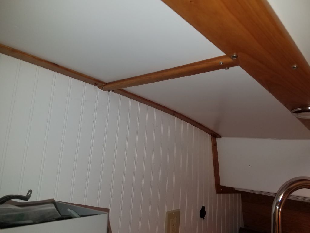
Over the past couple weeks, when I thought of it, I’d finished up the tiny repair to the bulkhead paneling in the galley, where I’d led the galley light wiring earlier. So now I could reinstall the wiring trim I’d made to cover the short wire run.
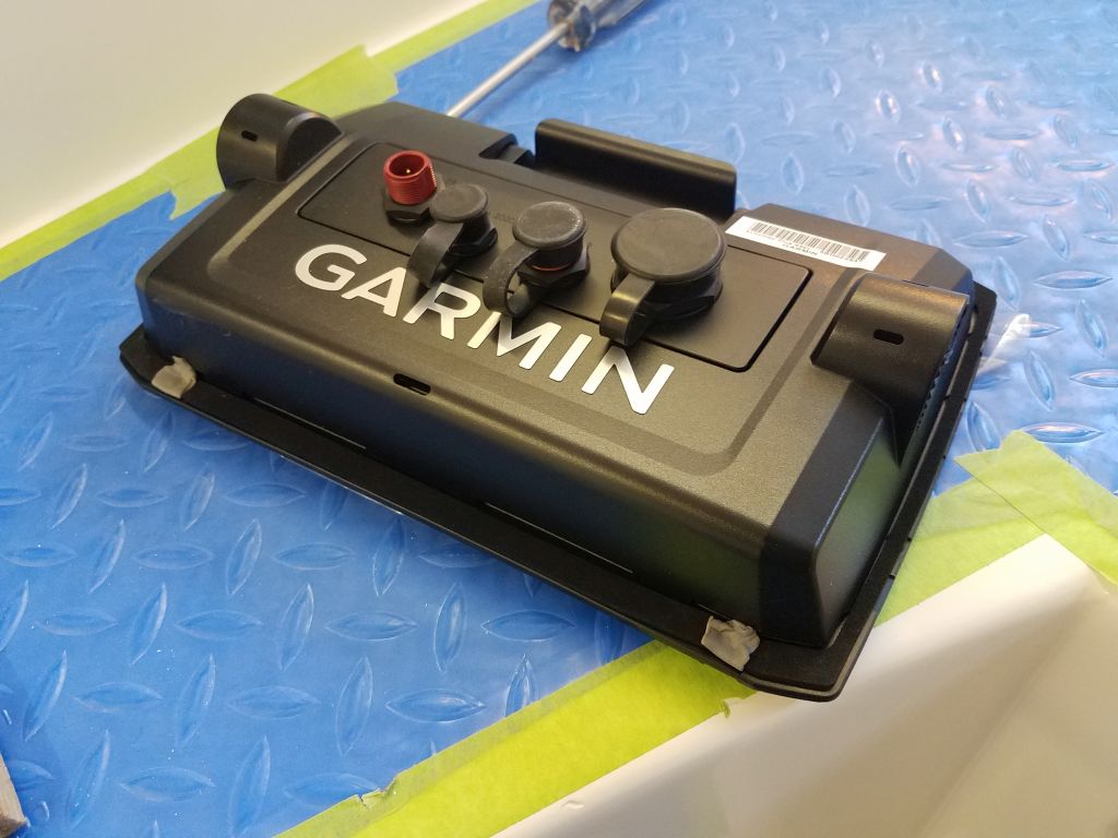
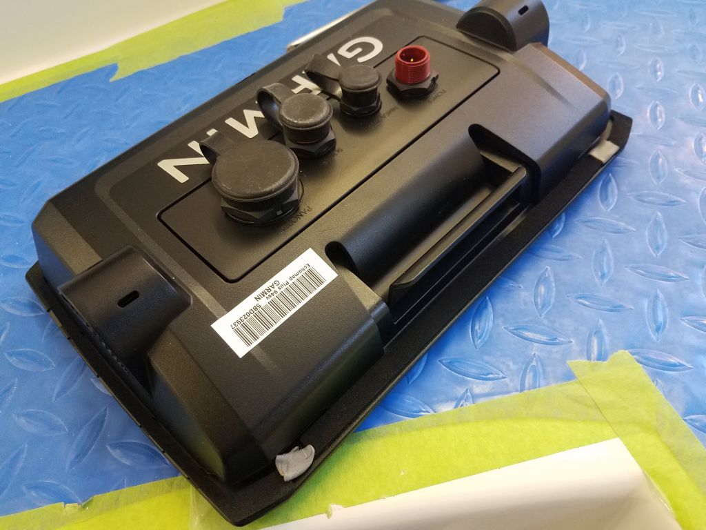
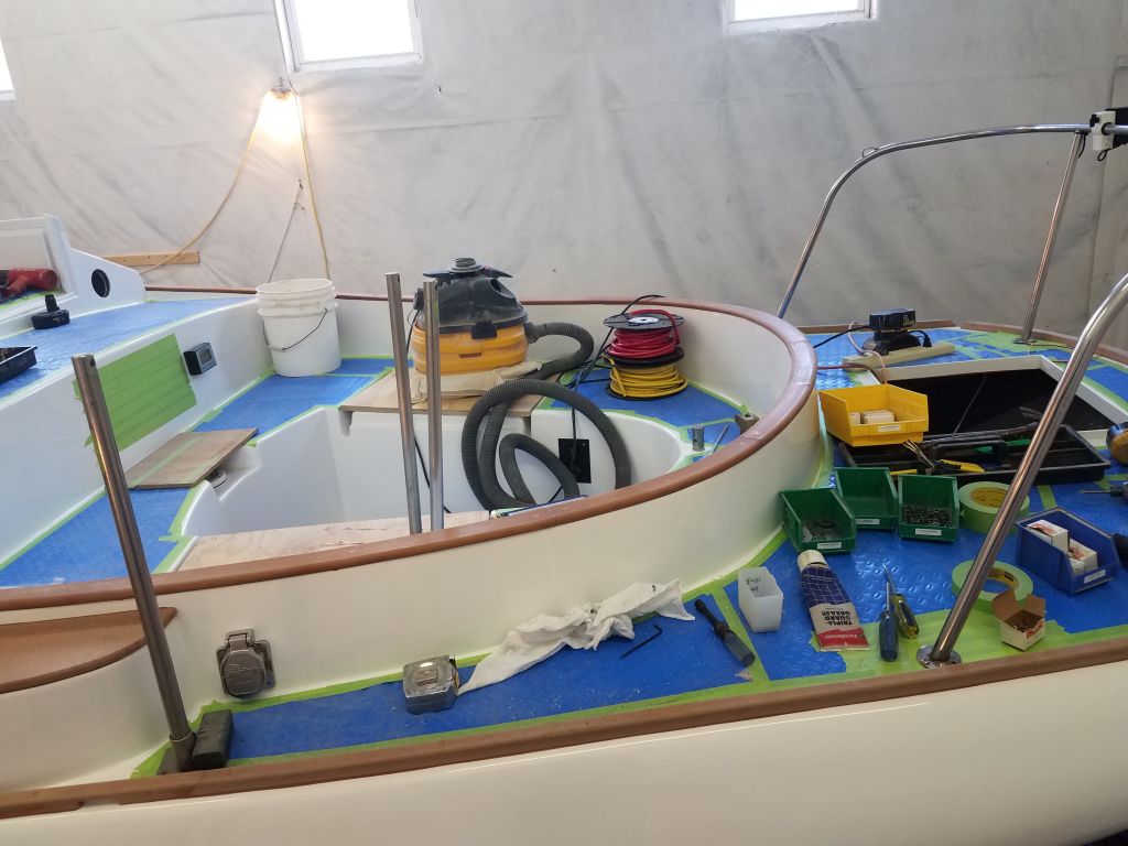
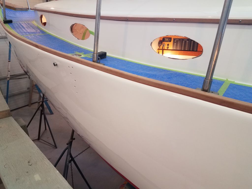
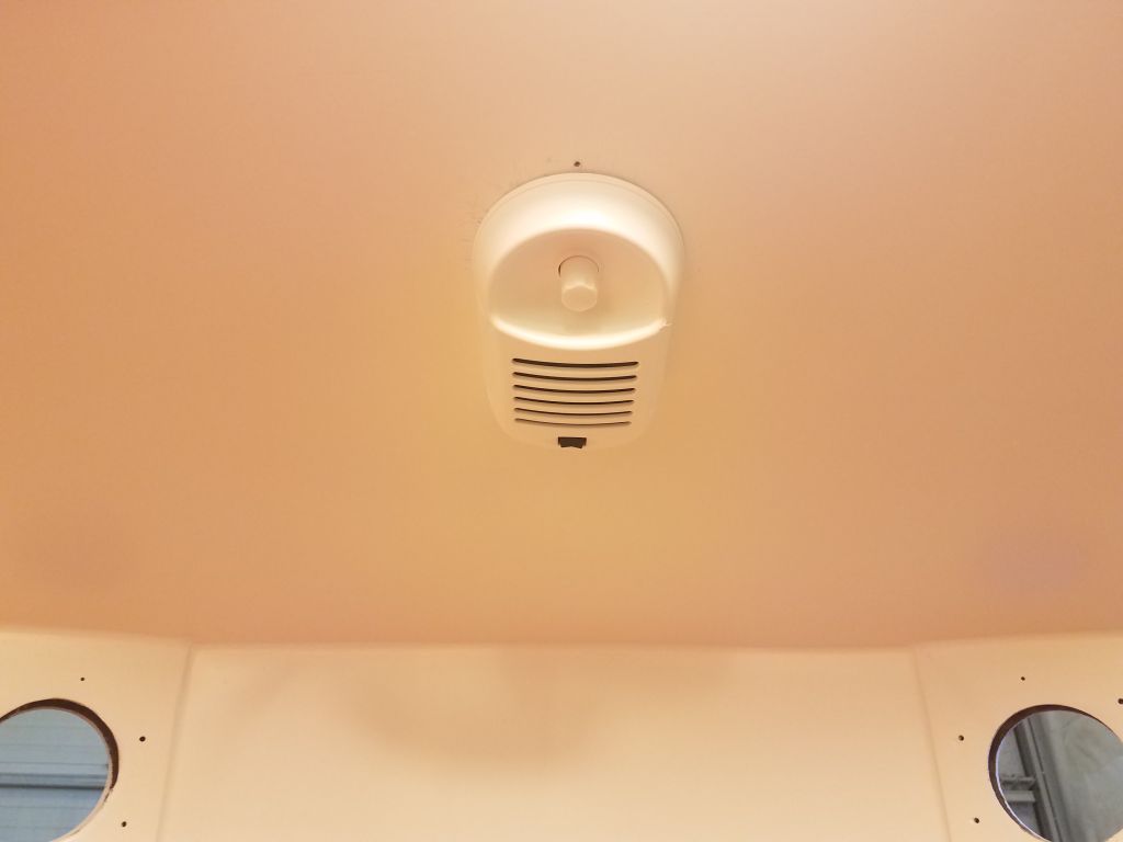
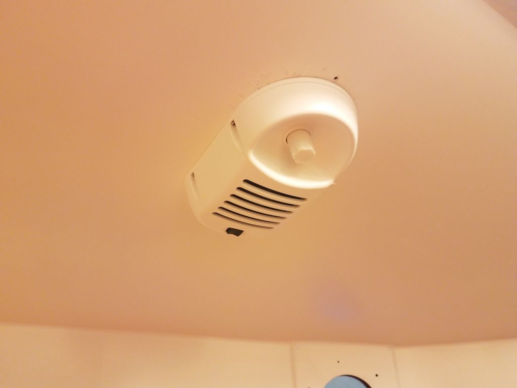
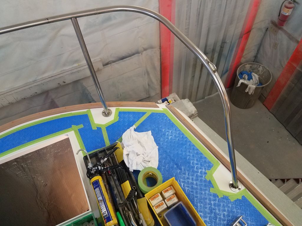
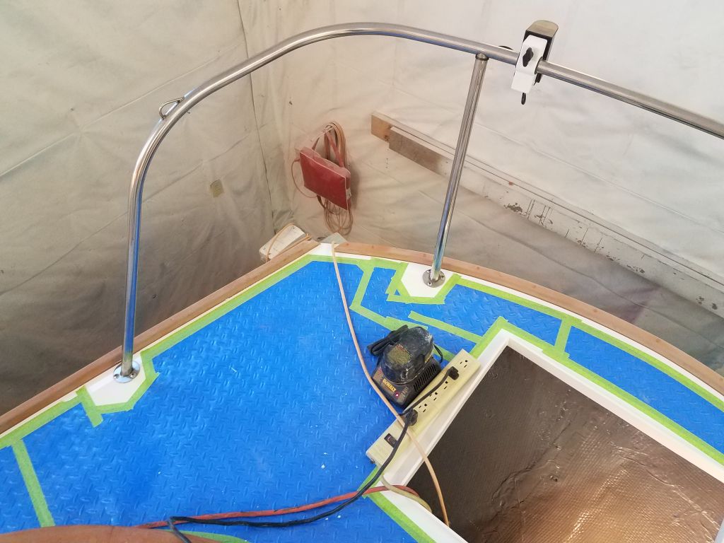
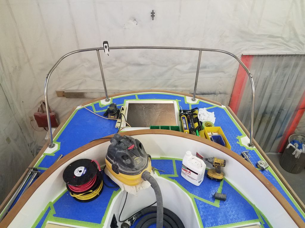
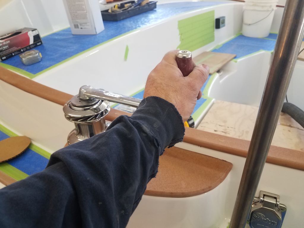
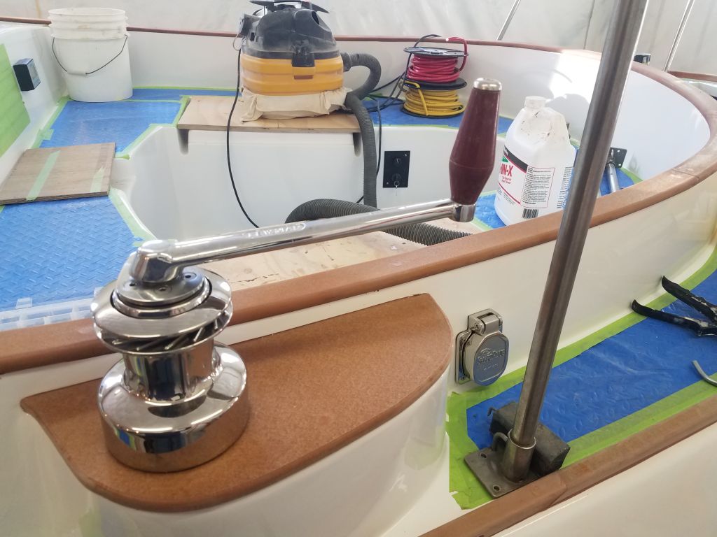
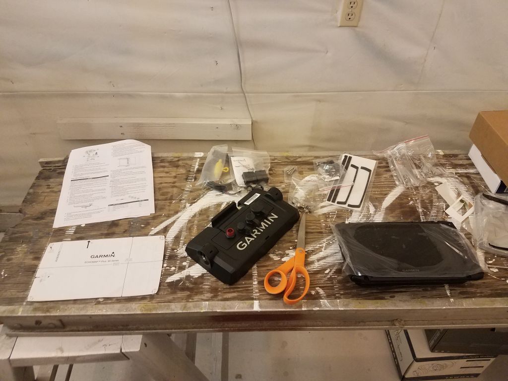
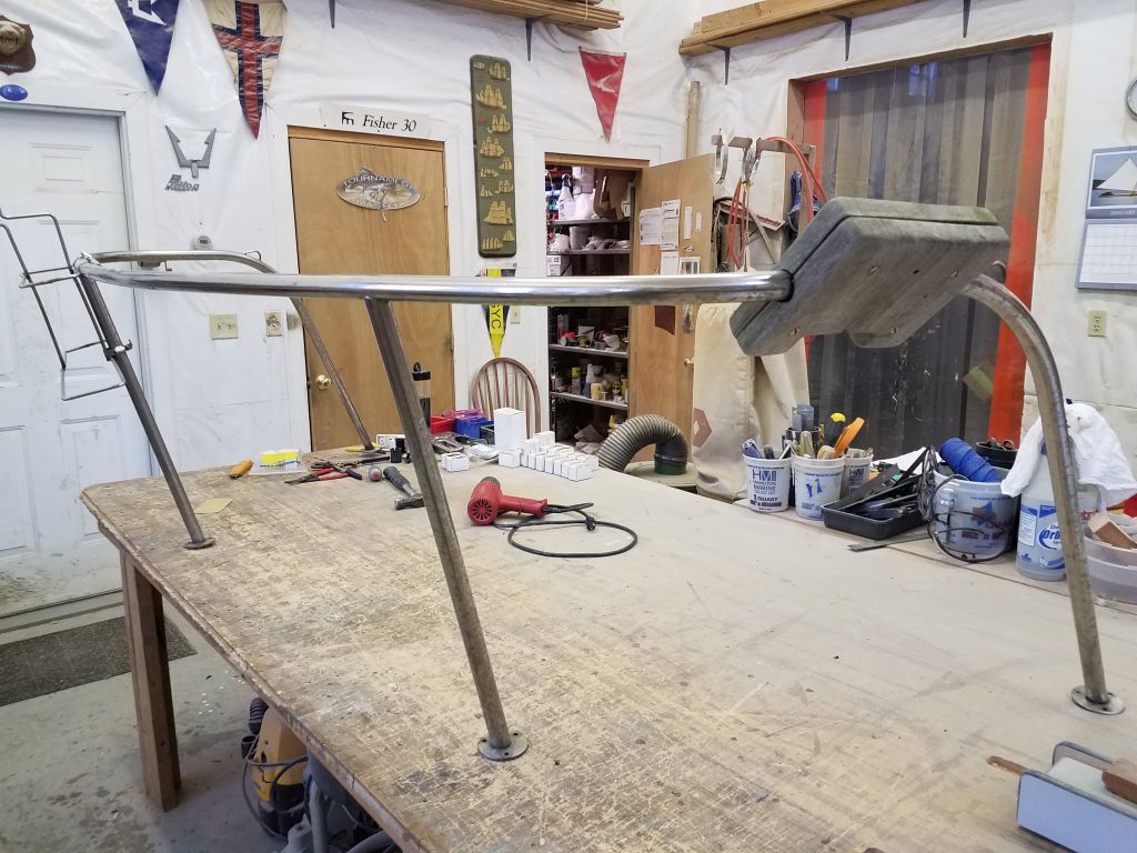
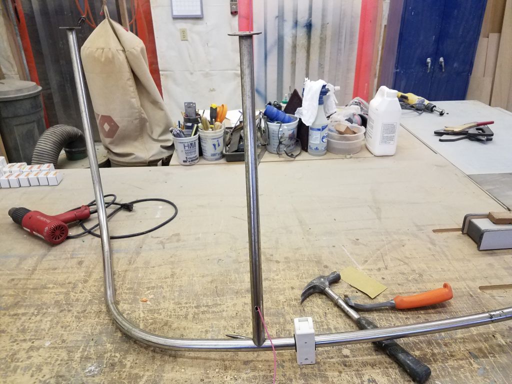
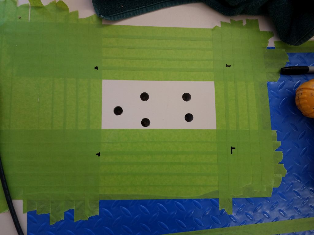
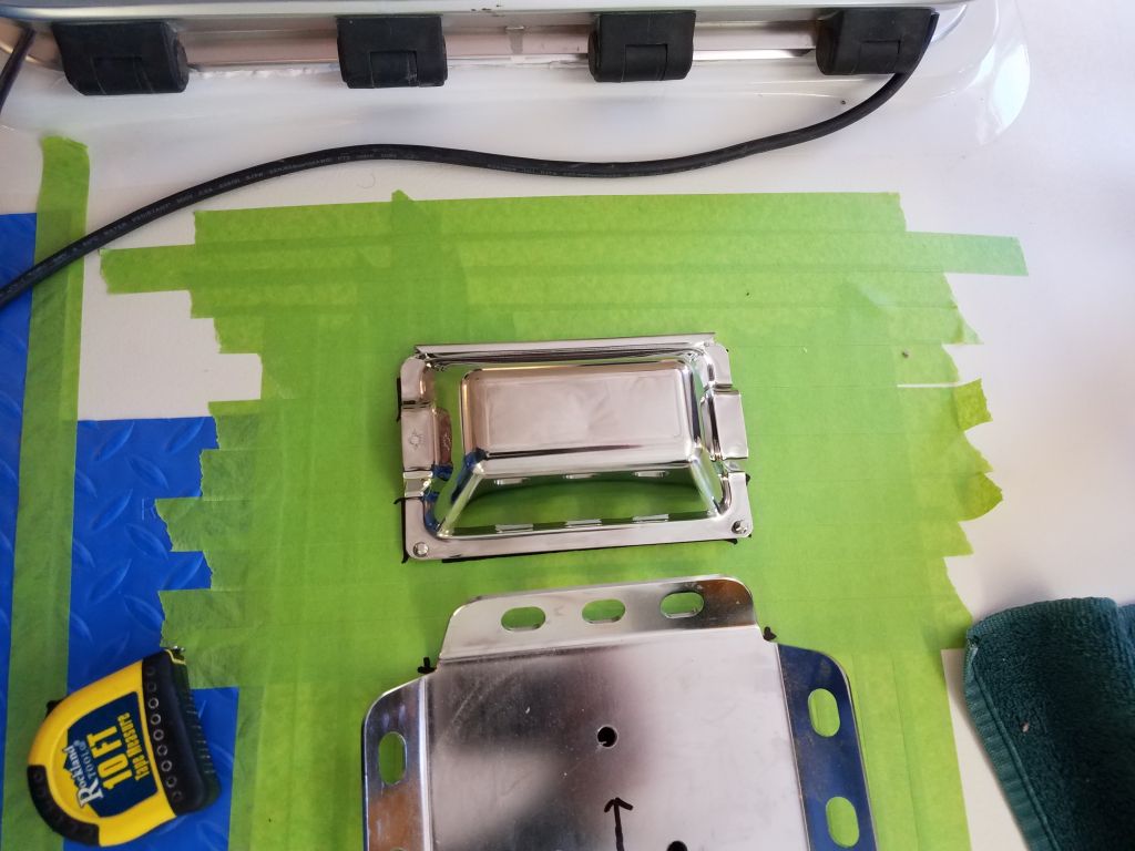
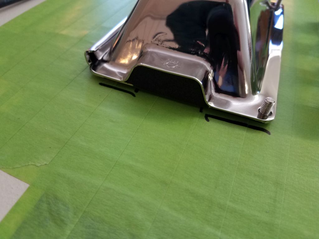
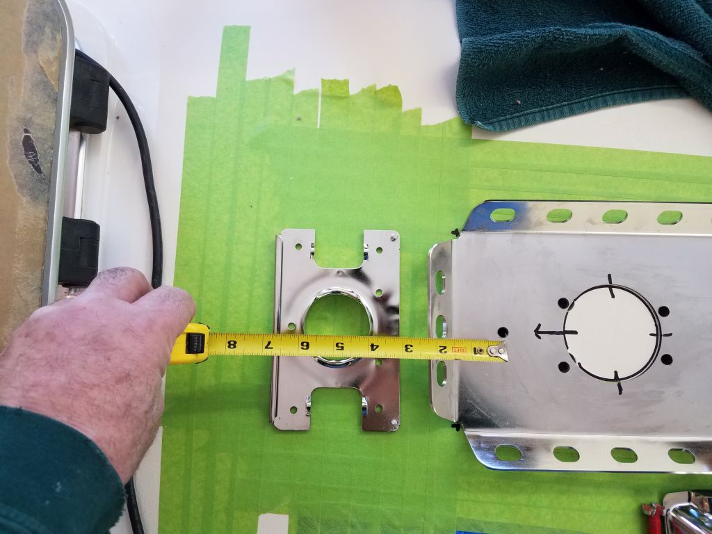
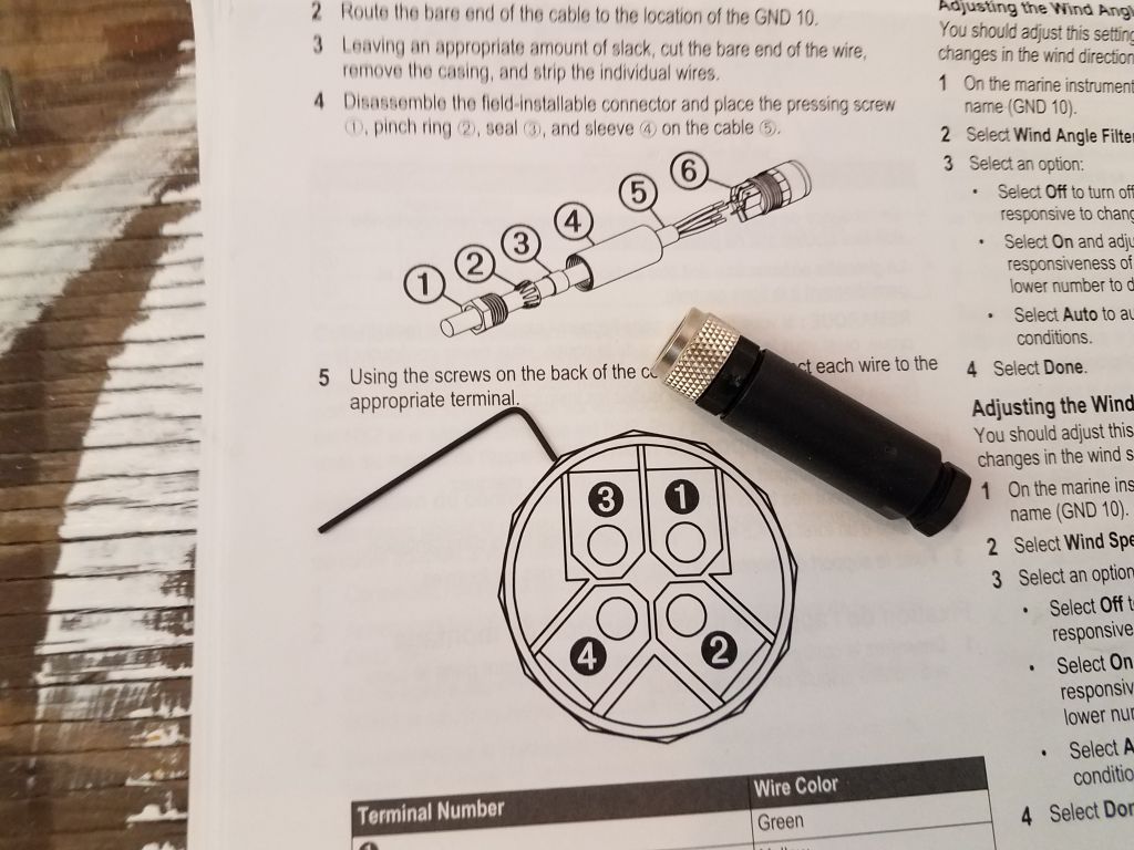
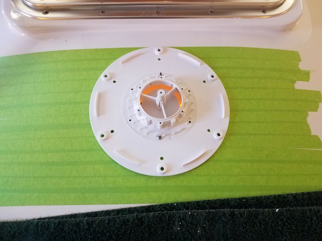
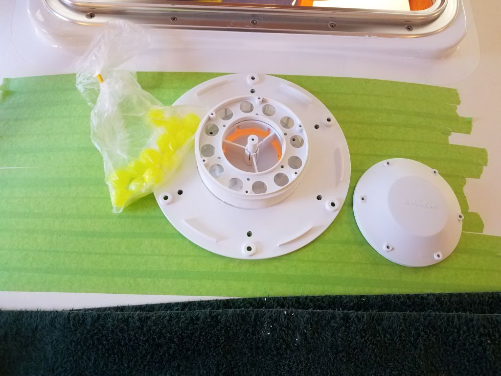
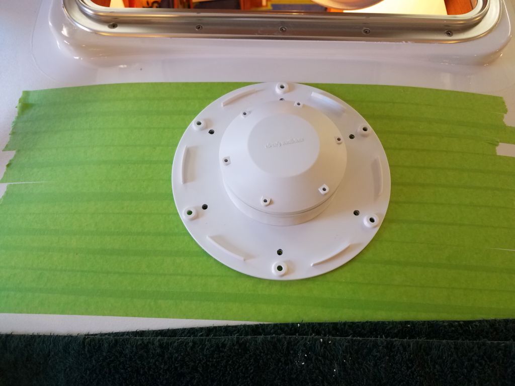
I unpacked and went through the new windlass and its accessories so I could plan the installation. The installation would include a circuit breaker, the windlass control/contactor box, a deck-mounted wired remote for operation, and a backup rocker switch to be mounted in the cabin for emergency use. In recent days as I’d been mulling over the installation, I’d had the thought that the contactor box would work well inside the small locker at the forward end of the v-berth, which locker was adjacent to but protected from the chainlocker, and convenient from an installation and wiring perspective as well. With that plan in mind, and a better sense of the overall installation ahead, I ordered some specific lugs I’d need to connect wiring to the contactor terminals, and moved on to other things for now.

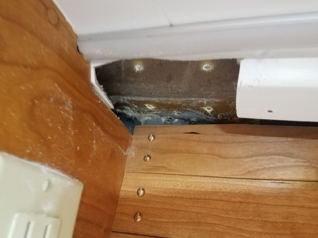
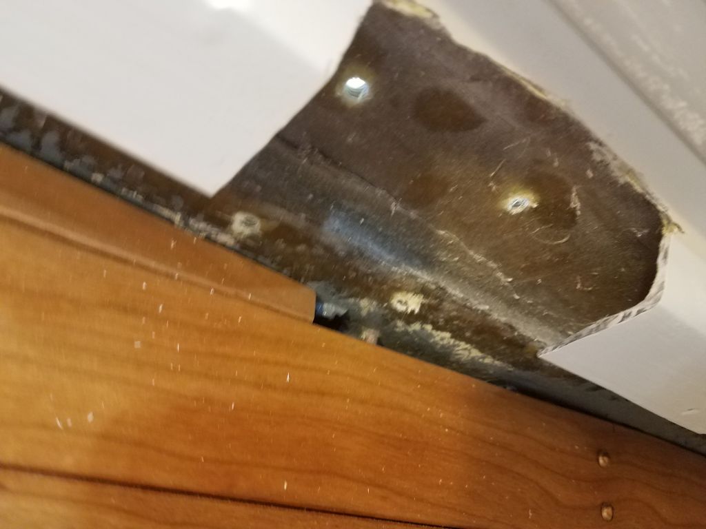
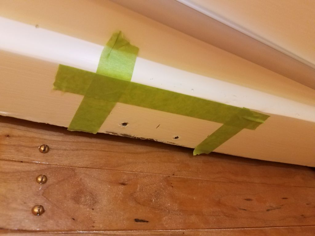
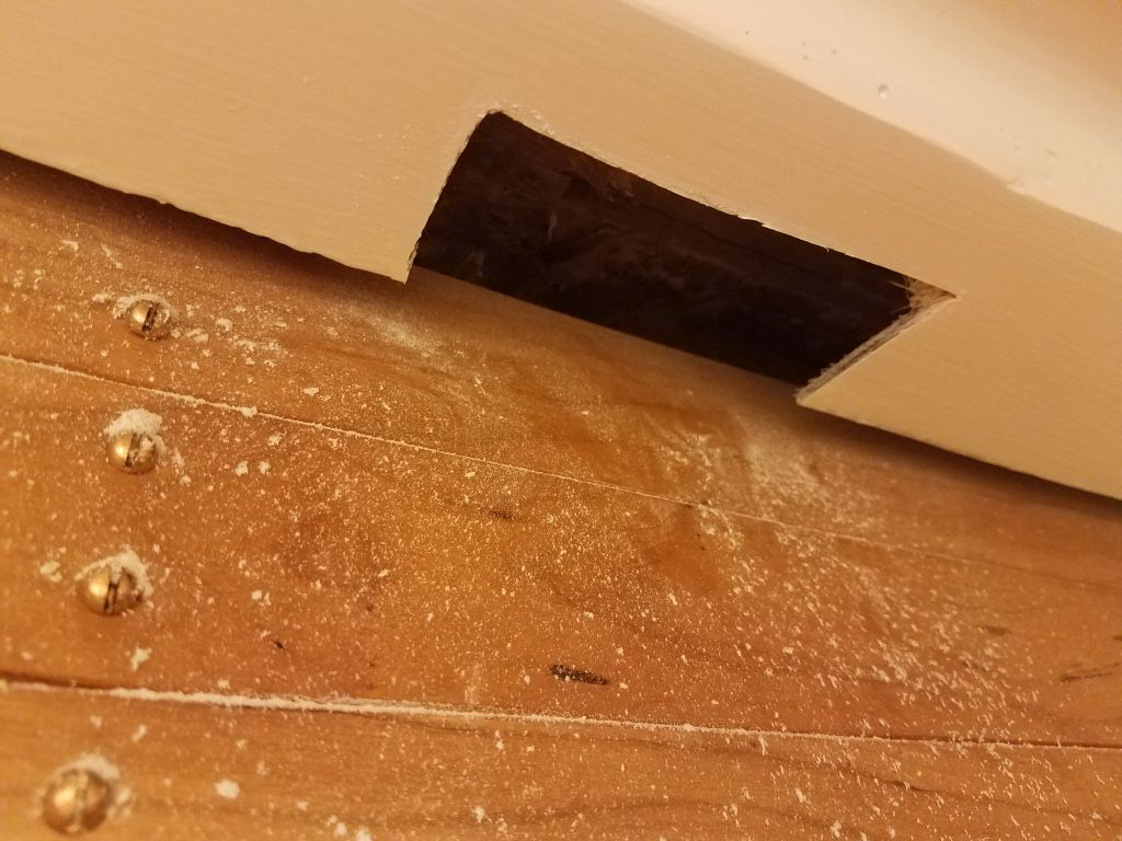
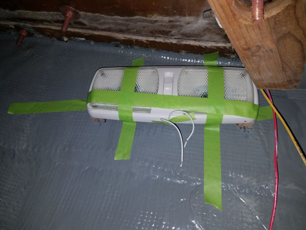
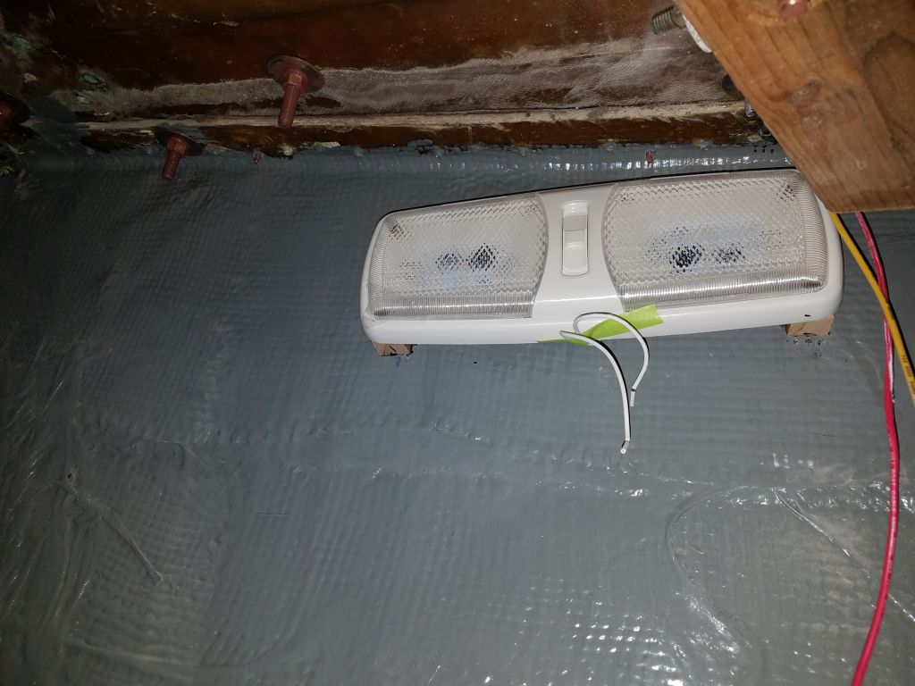
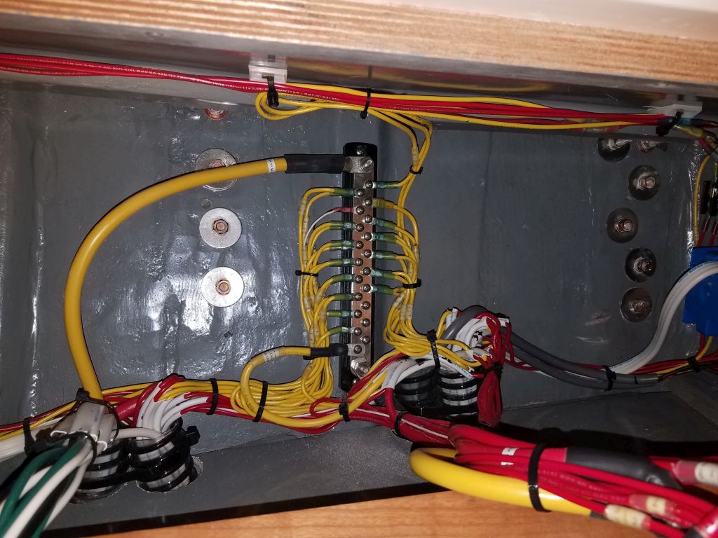
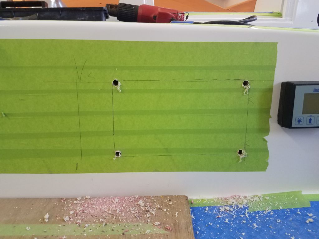
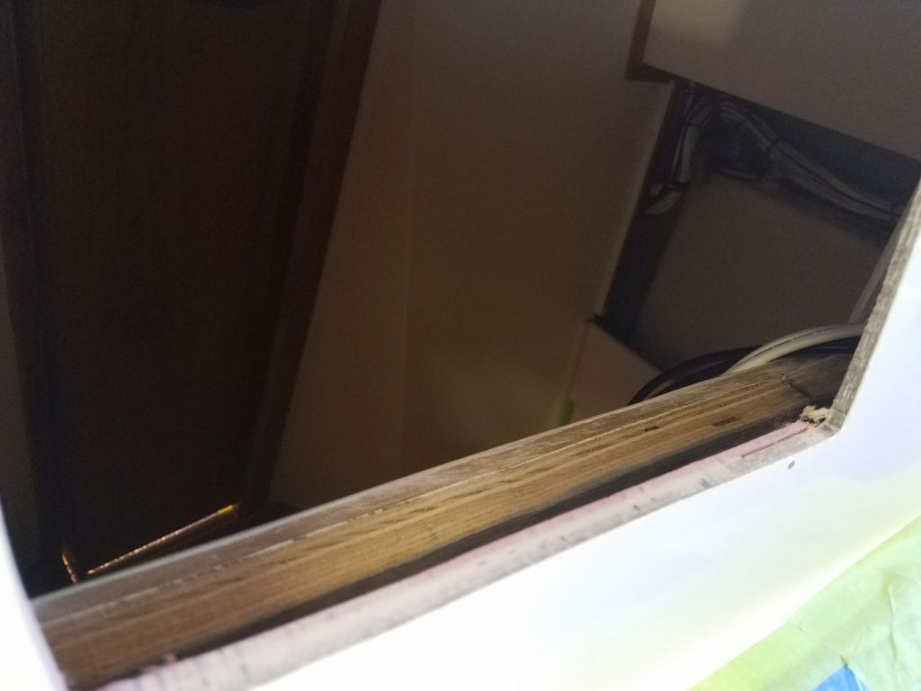
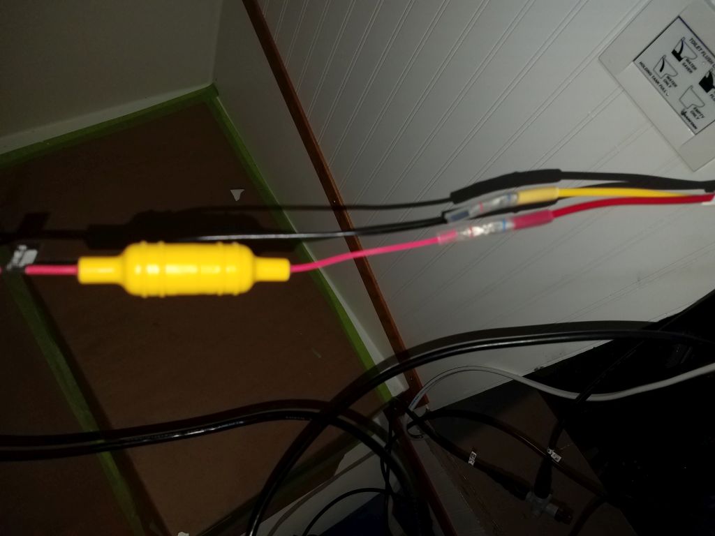
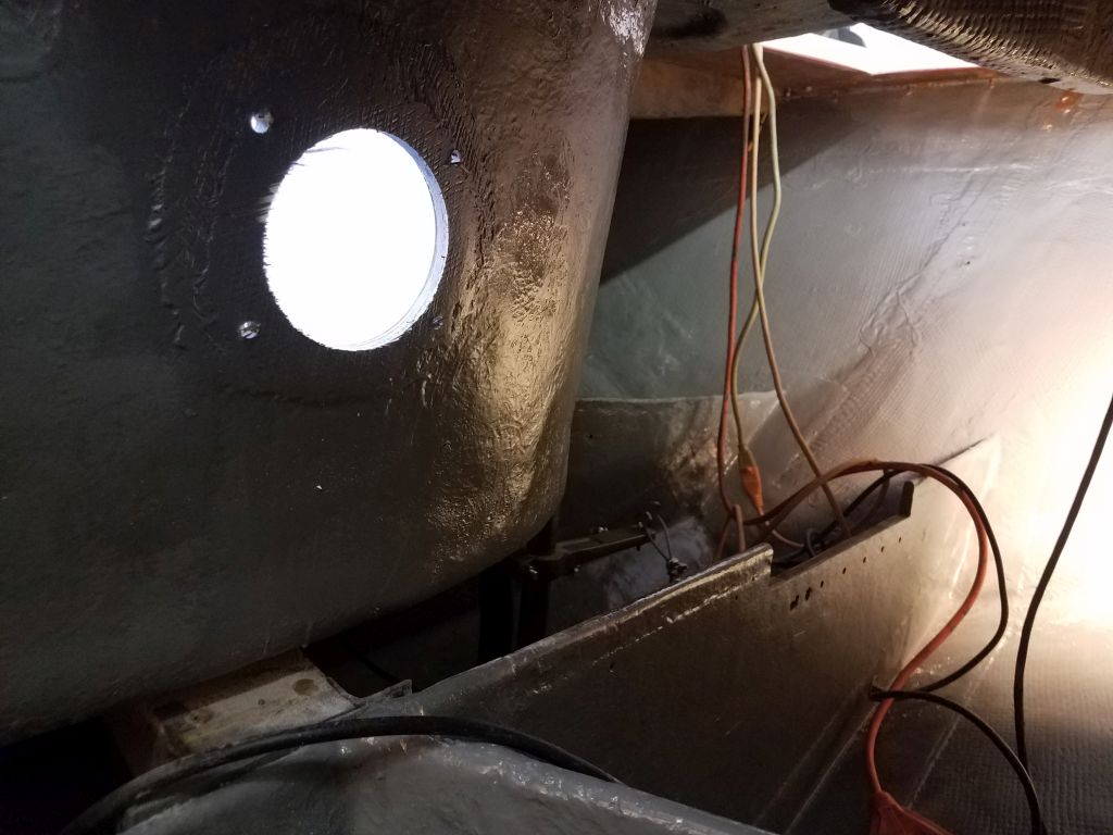
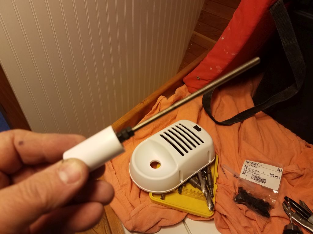
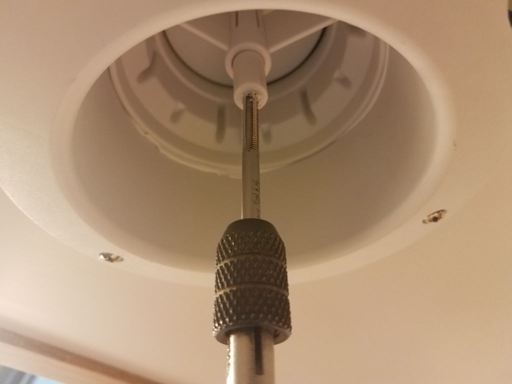
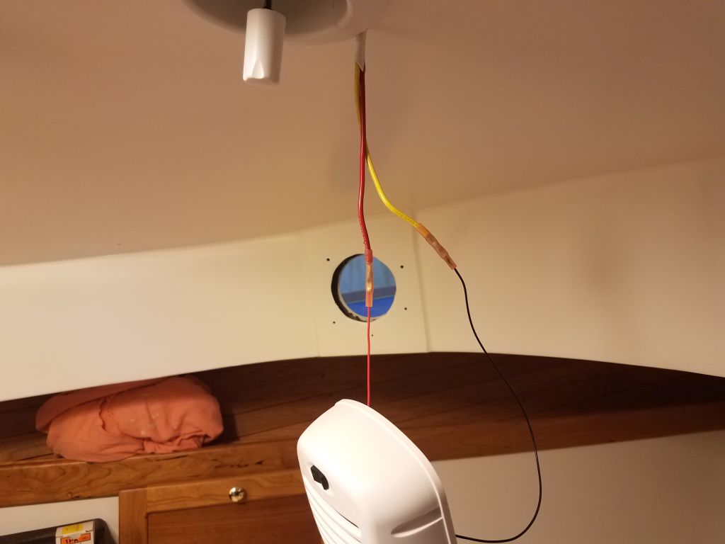
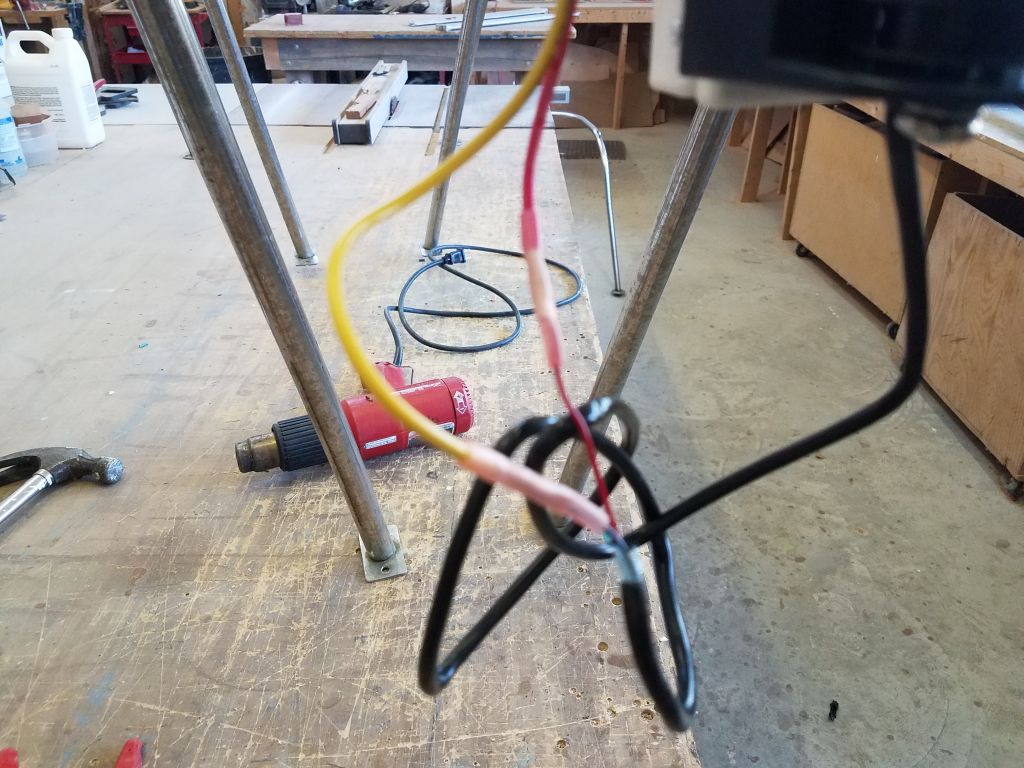
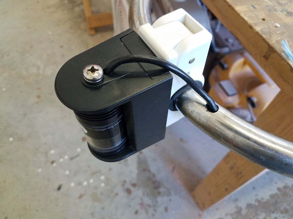
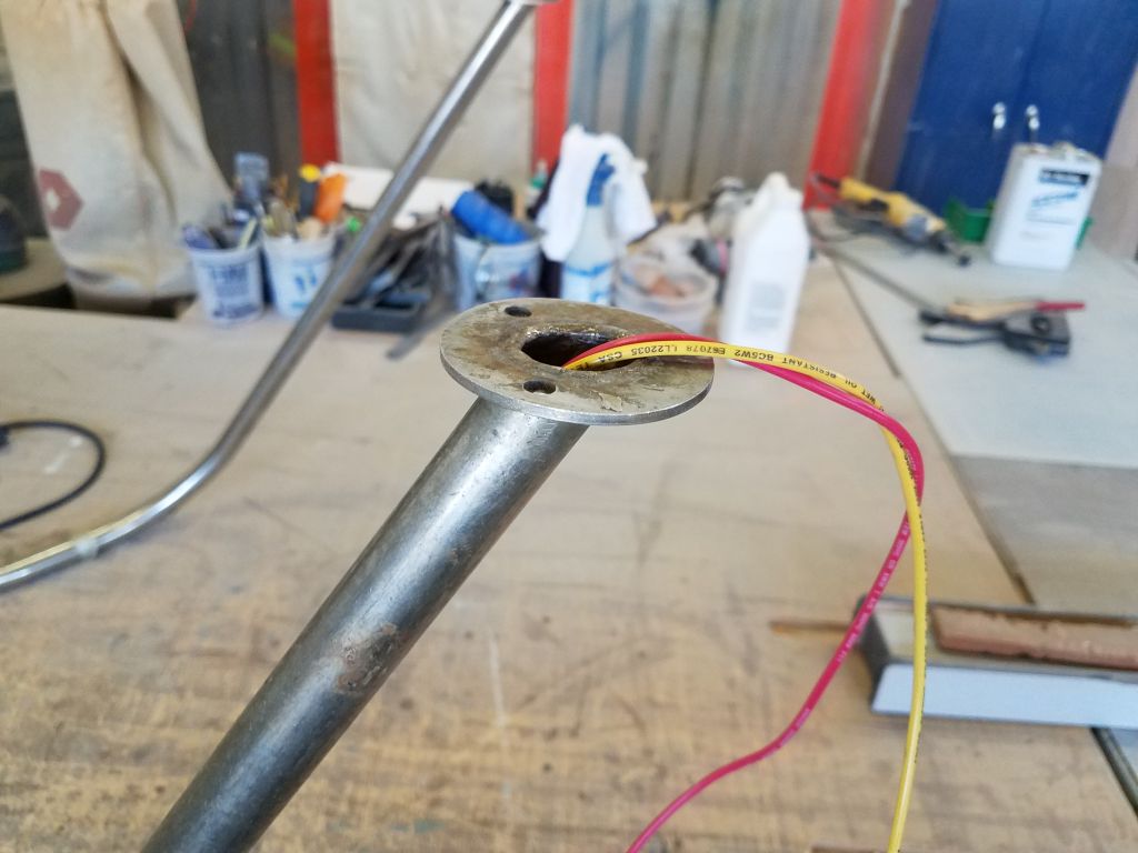
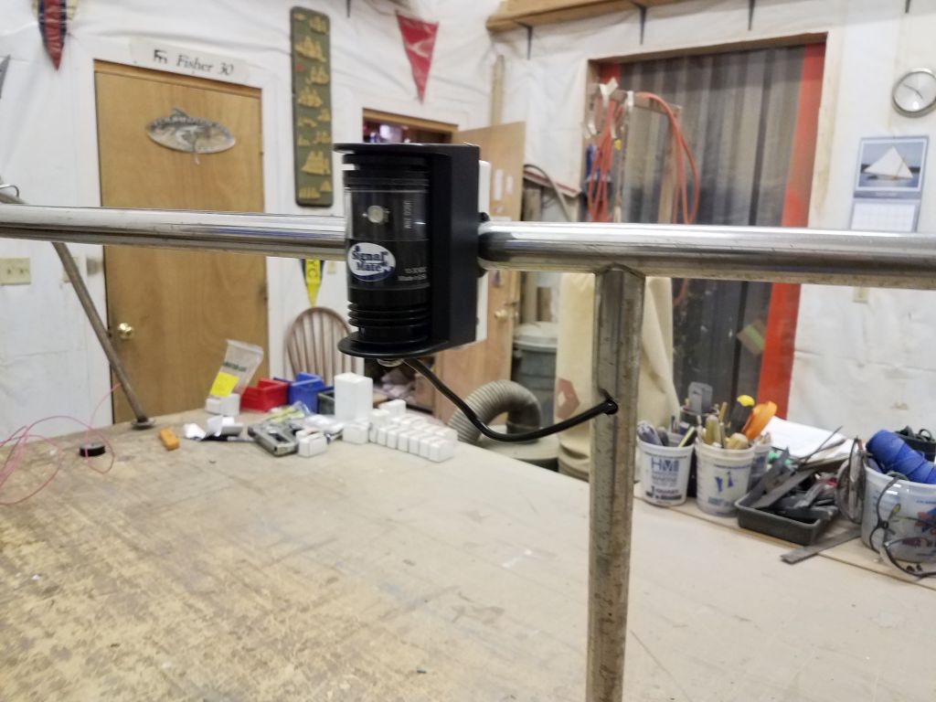
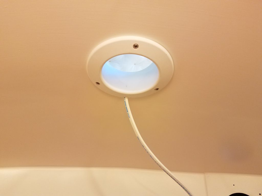
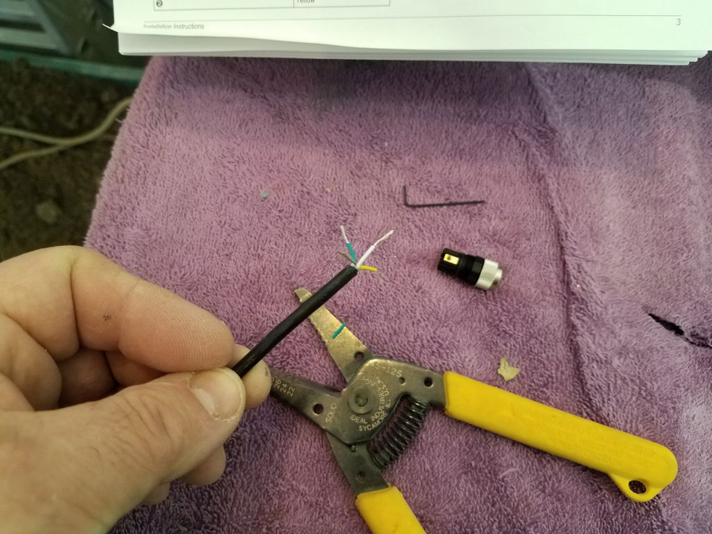
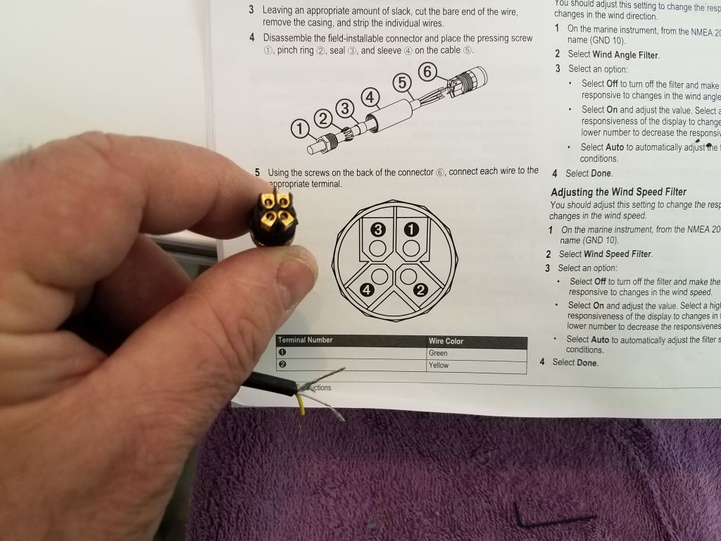
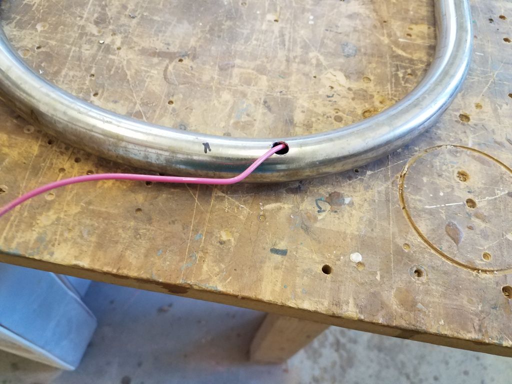
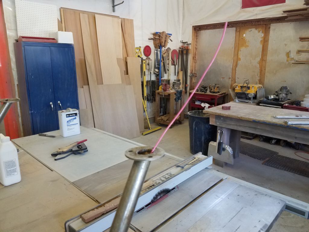
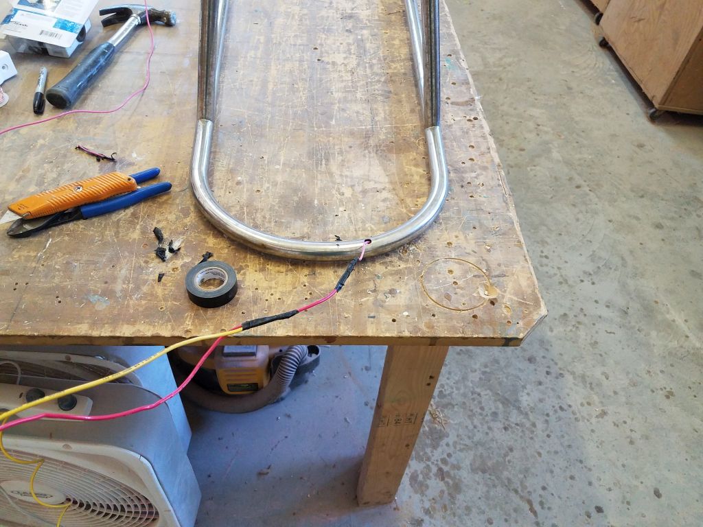
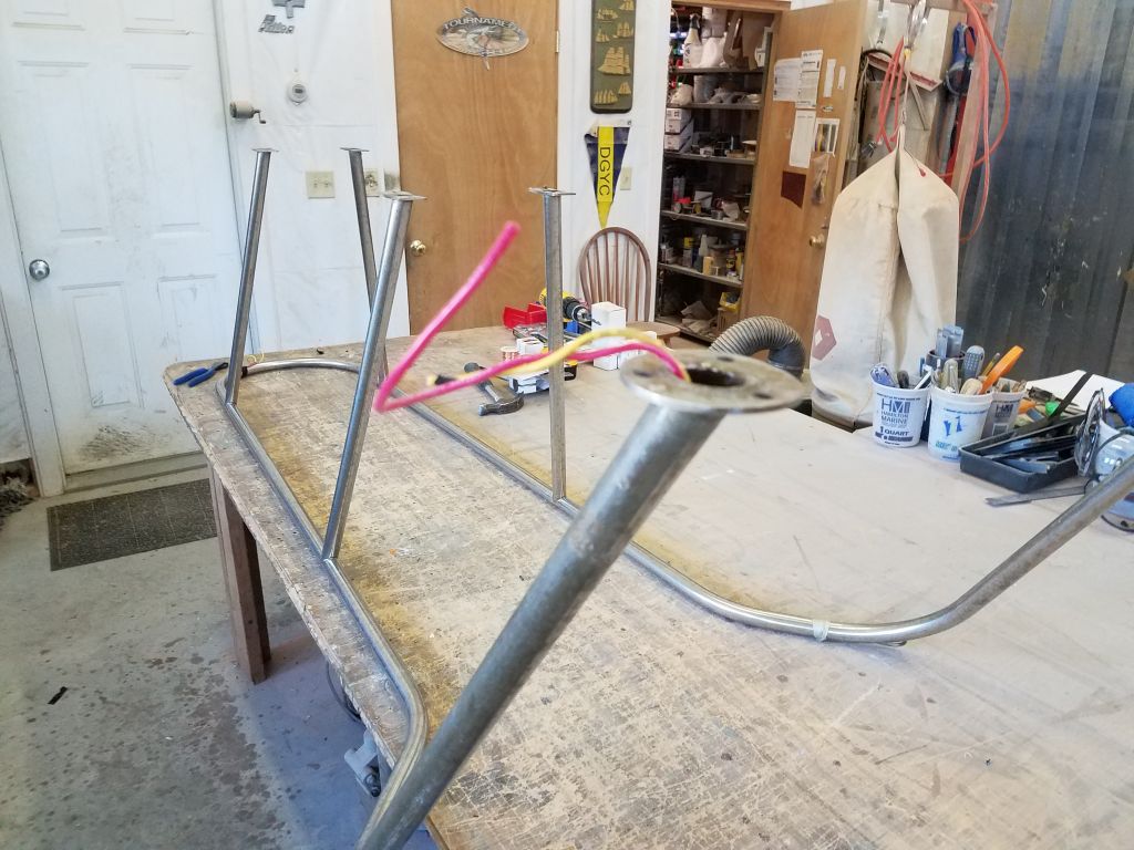
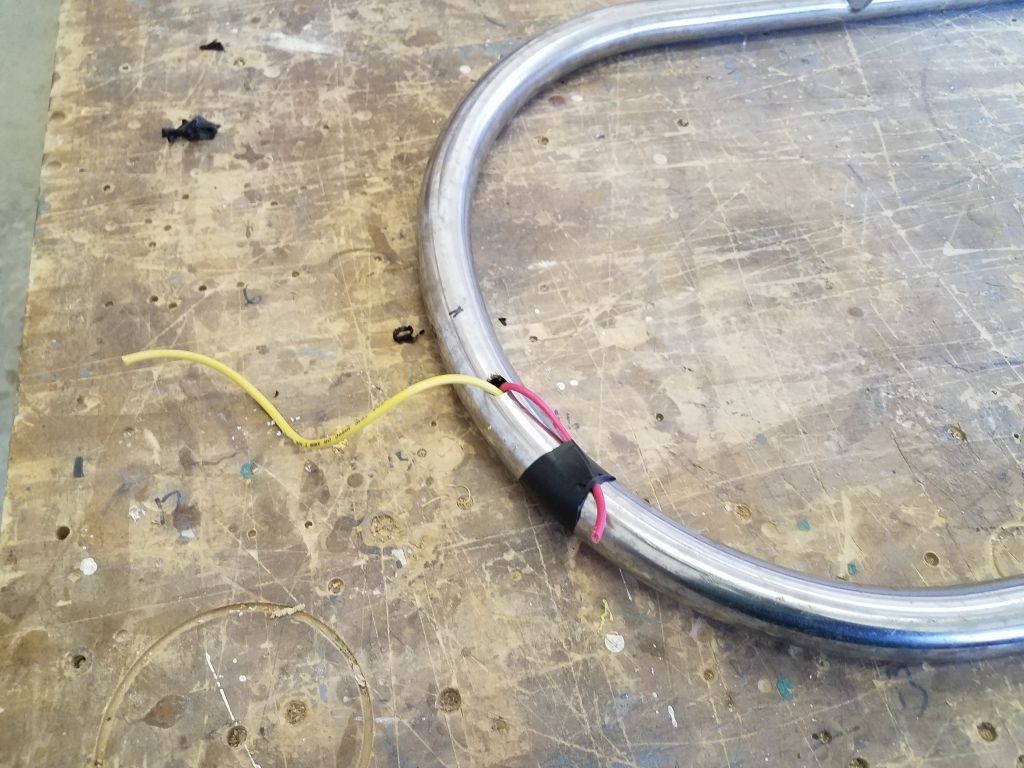
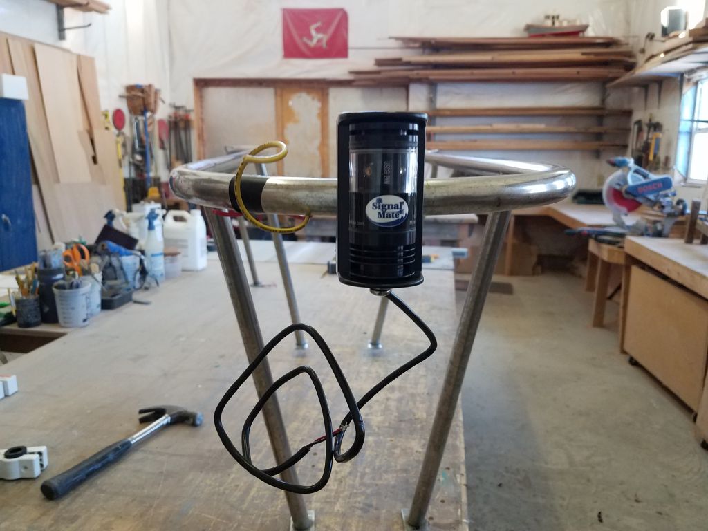
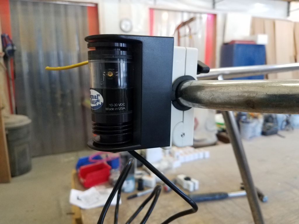
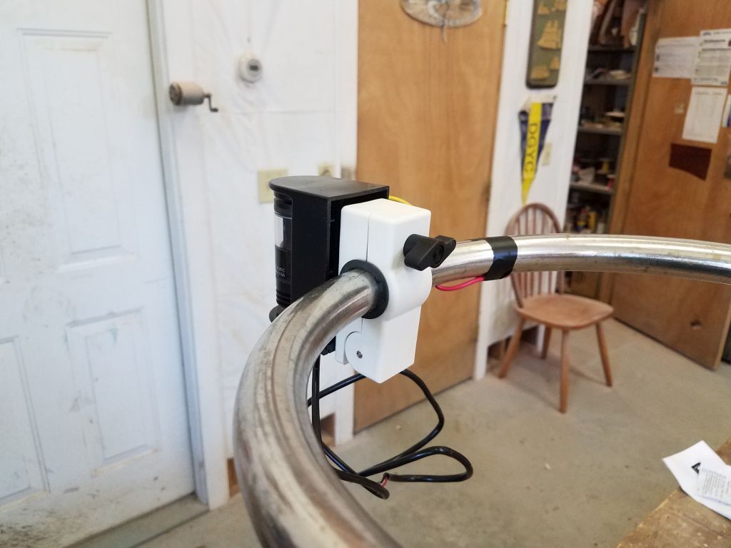
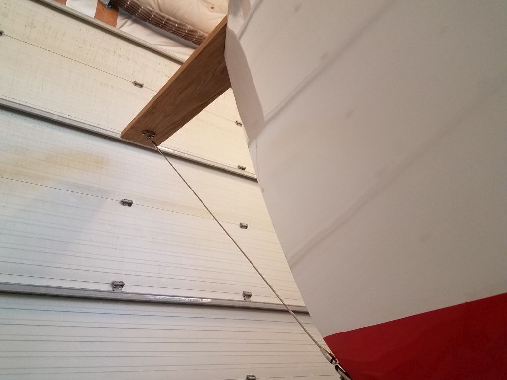
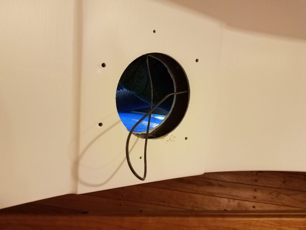
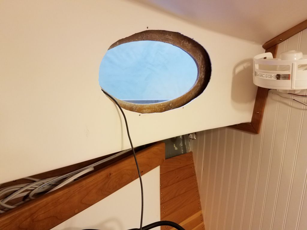
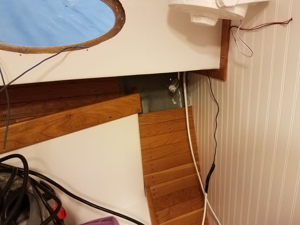
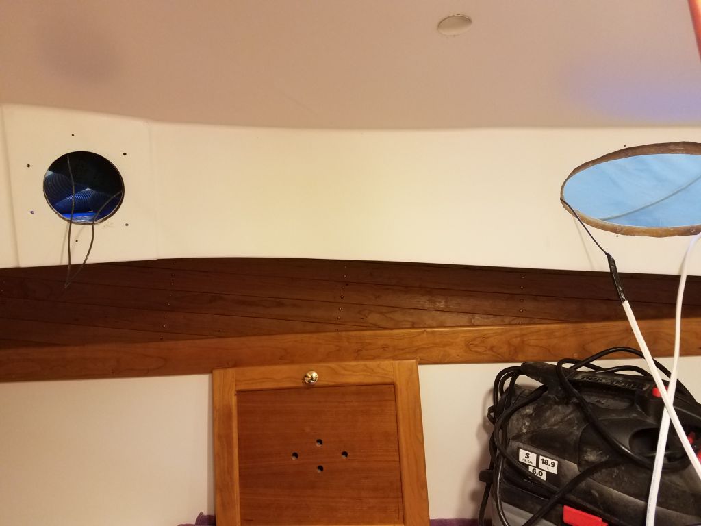
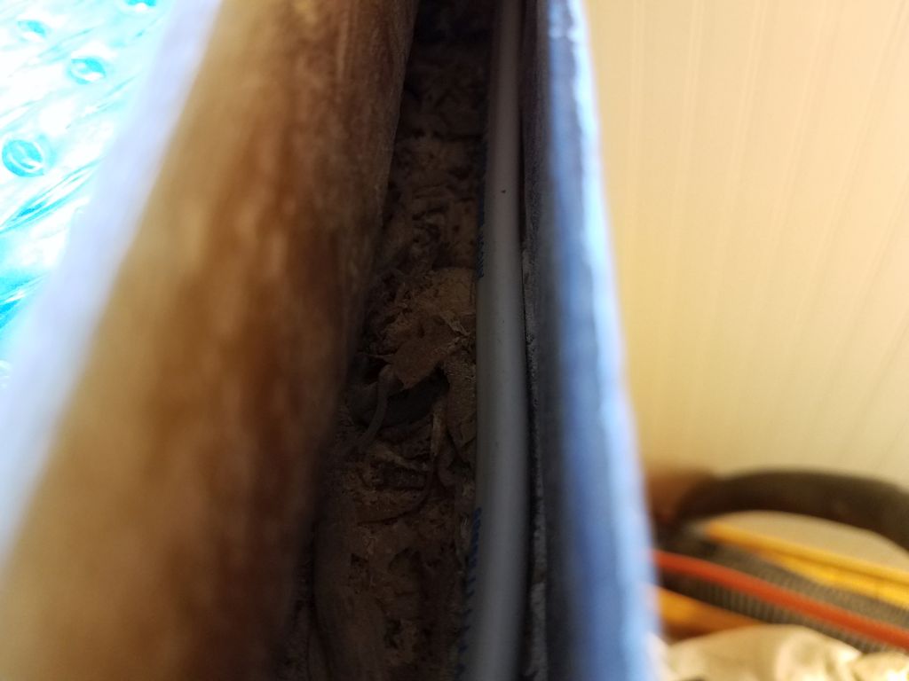
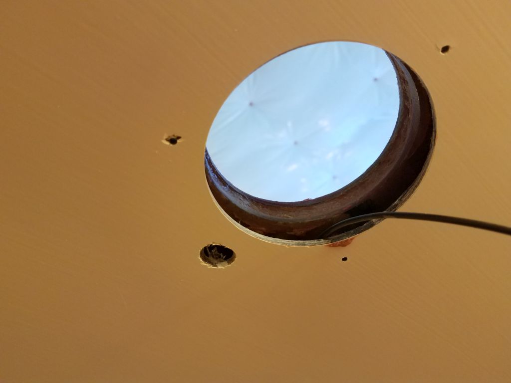
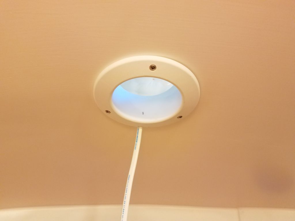
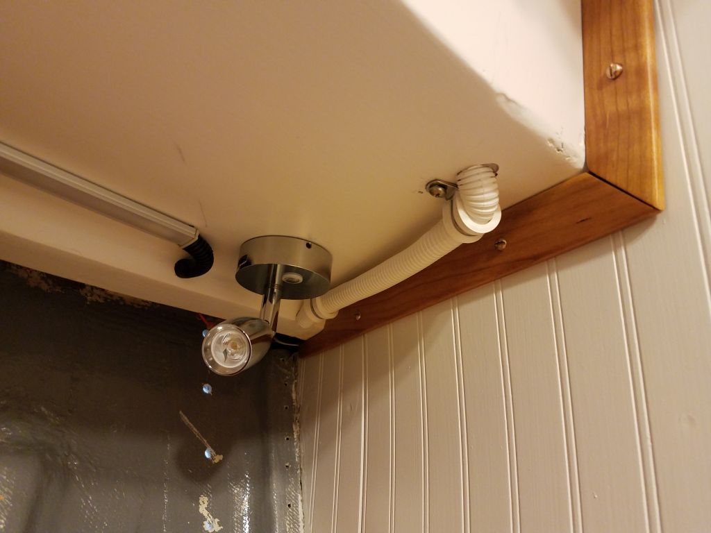
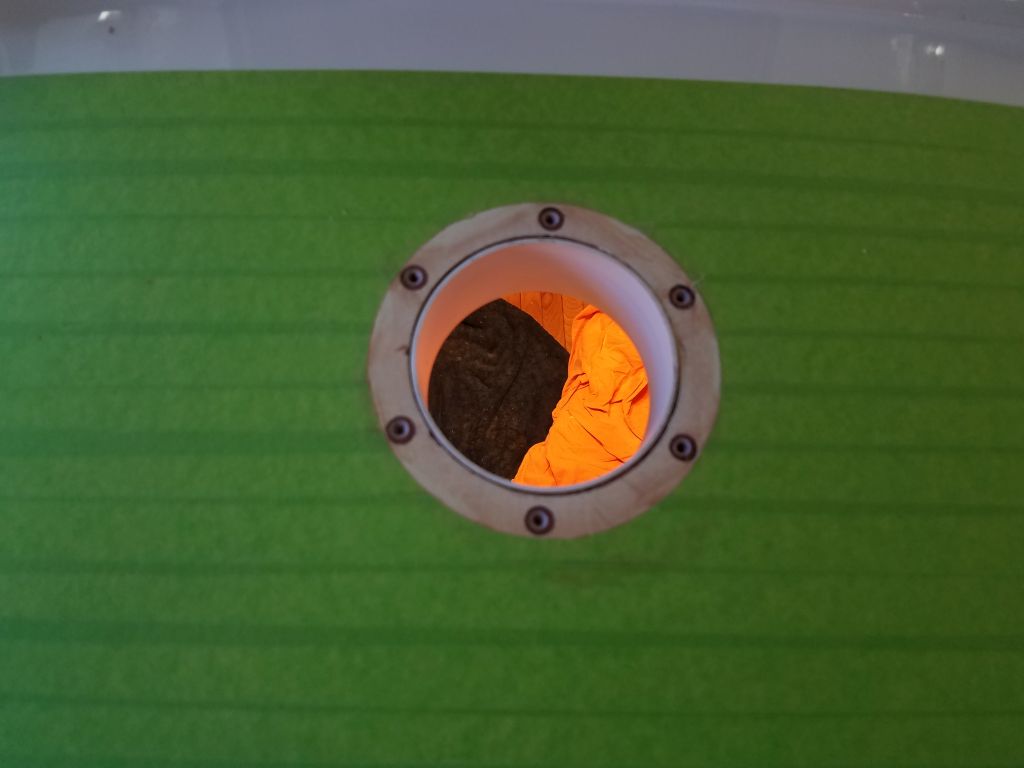
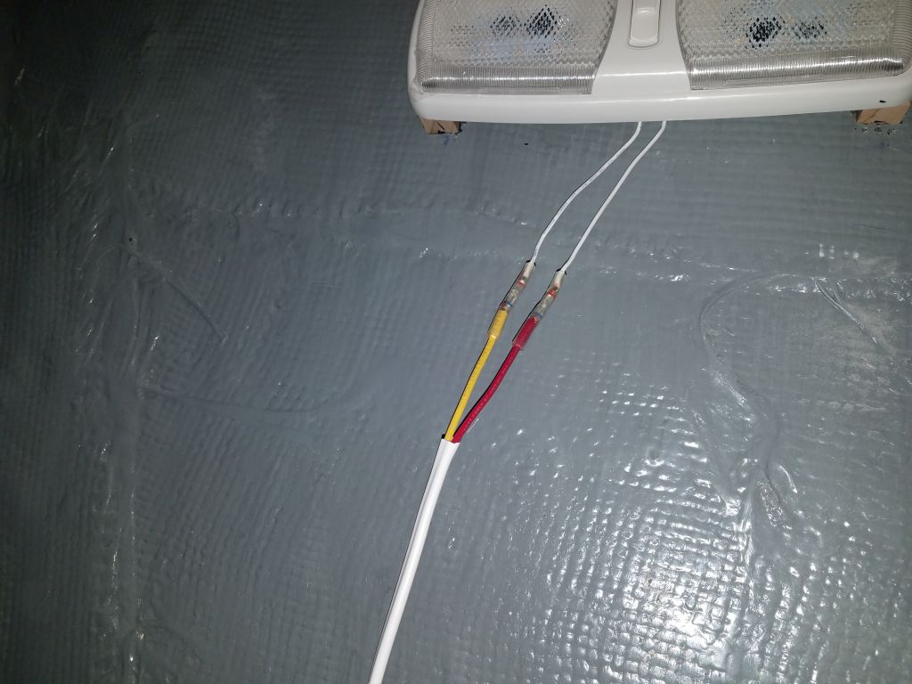
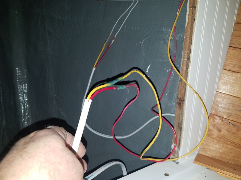
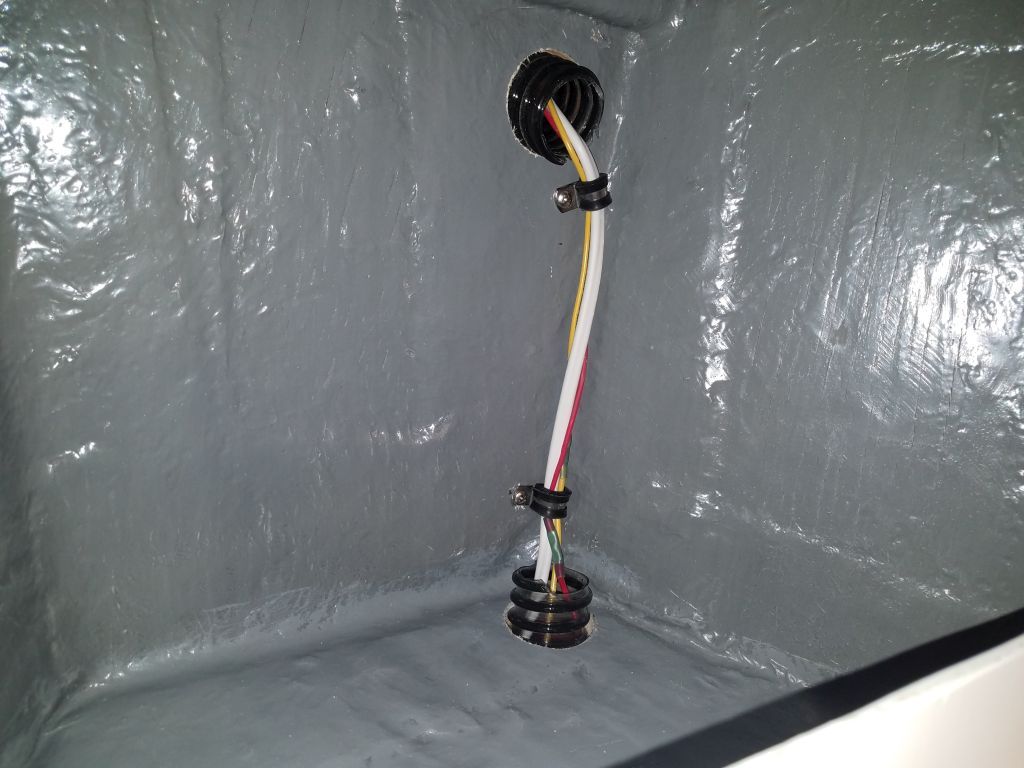
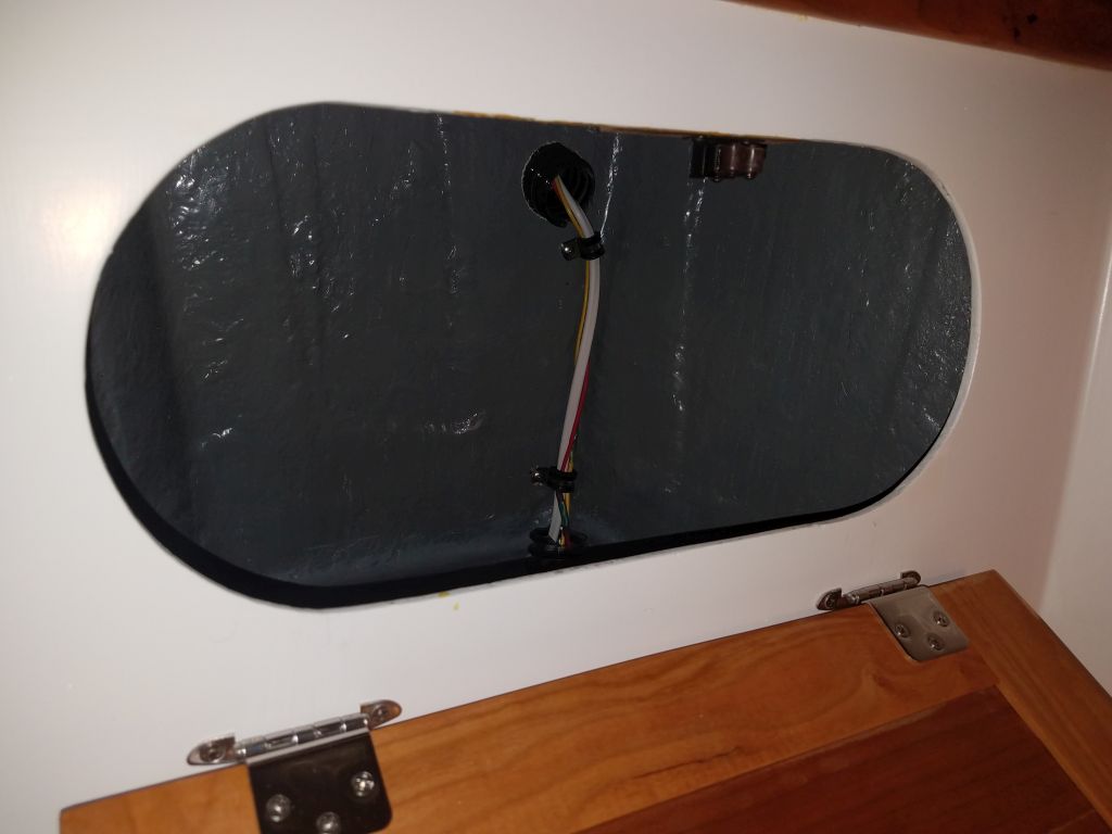
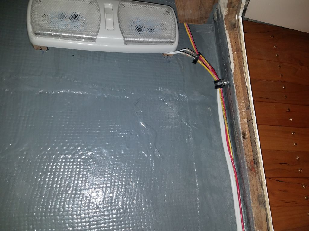
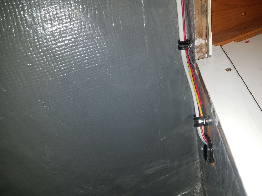
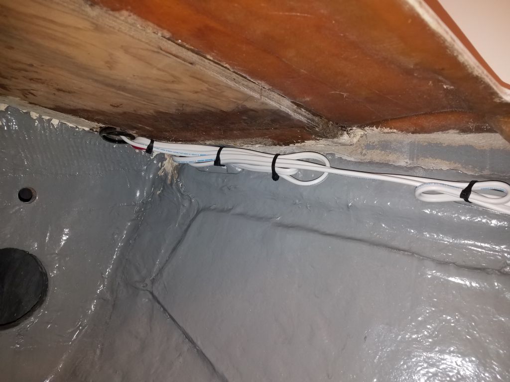
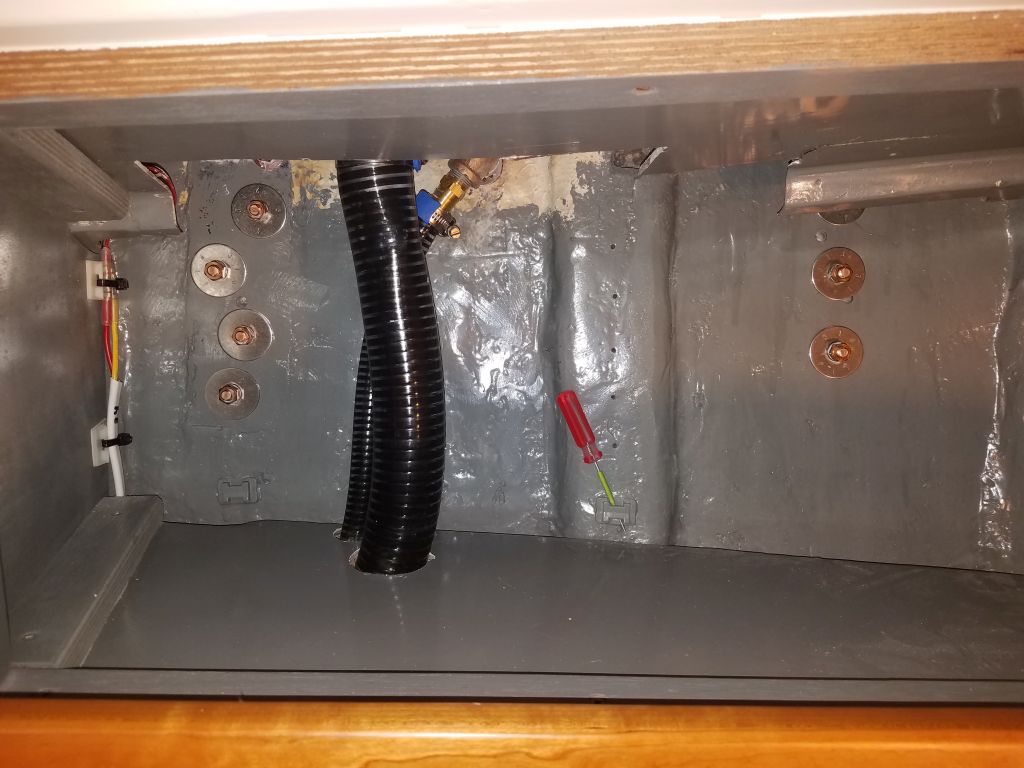
The wiring plan for the windlass tied in with the need to finish up the wiring for the forward running lights and the new light in the chainlocker. I’d previously run two circuits forward for these lights, leaving ample excess wire beneath the v-berth to await final wiring details, and now was the time. I decided to run the wires up from below the berth and through the small forward locker, then into the chainlocker from there. This wire route would also accept the cables to and from the windlass. I used a hole saw to drill the holes required before running through the two wire pairs for the lighting circuits (adding hose in the new cutouts as chafe gear) before making up the wire connections and securing the wiring along the side of the chainlocker, and in the v-berth locker, as needed.

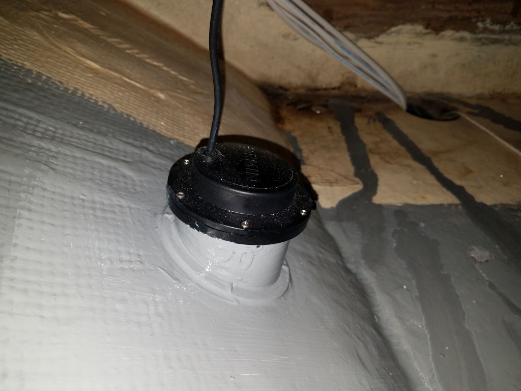
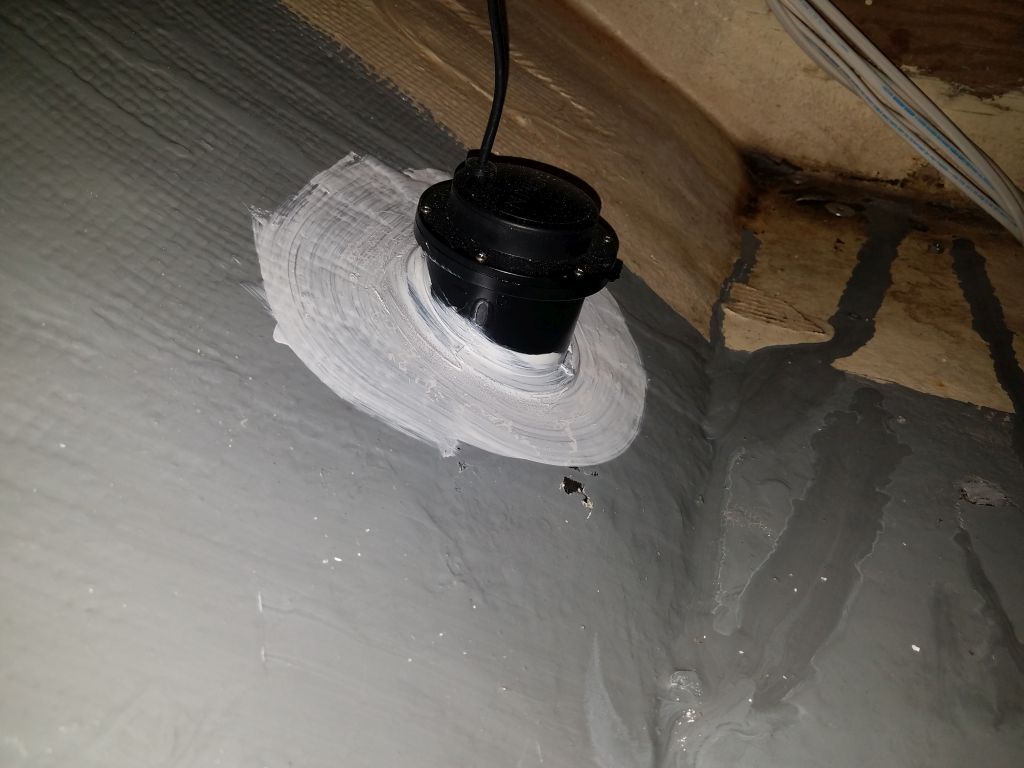
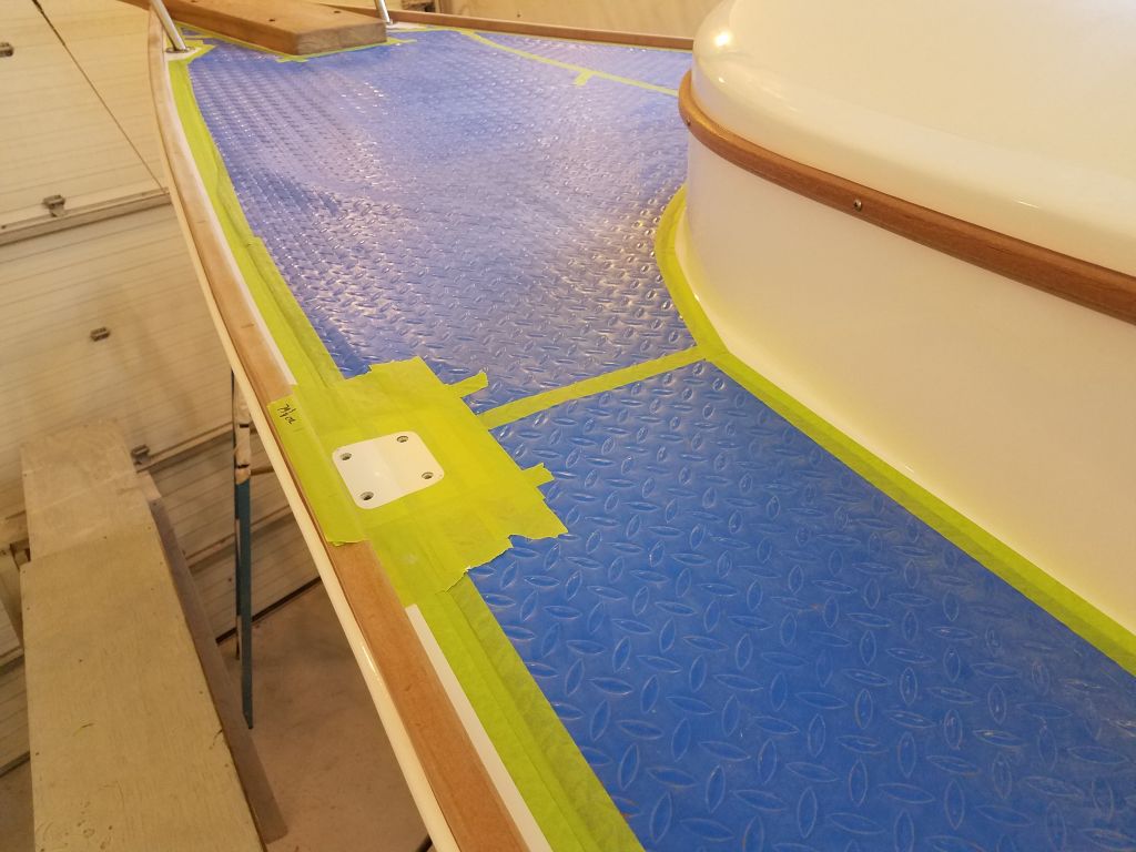
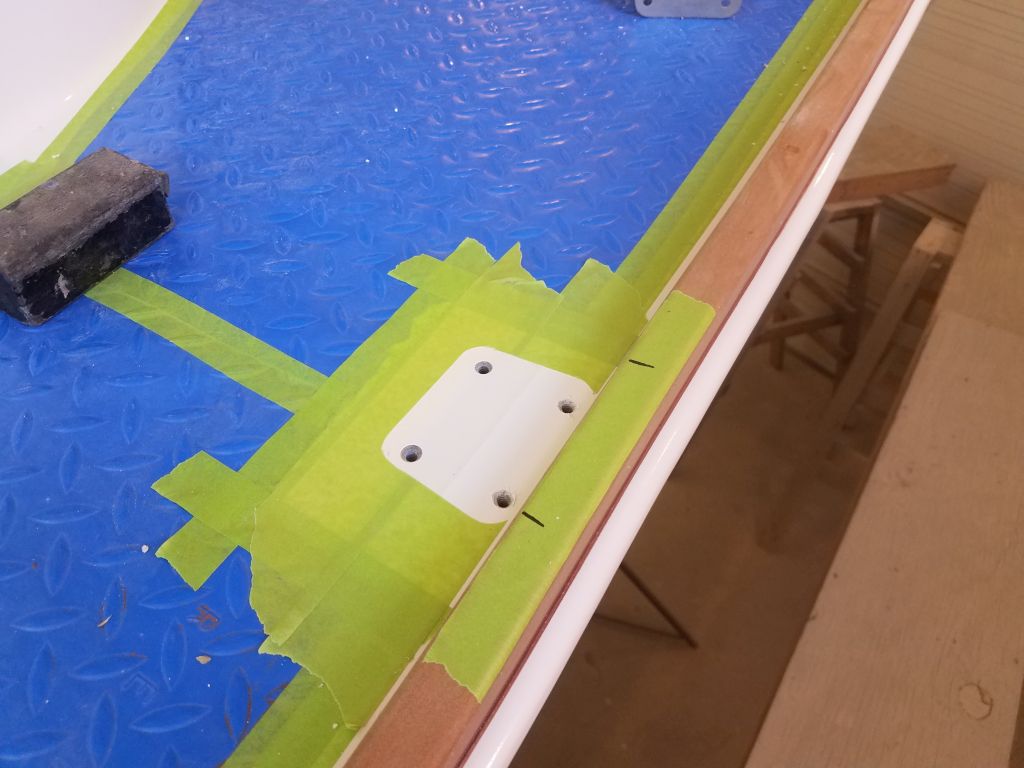
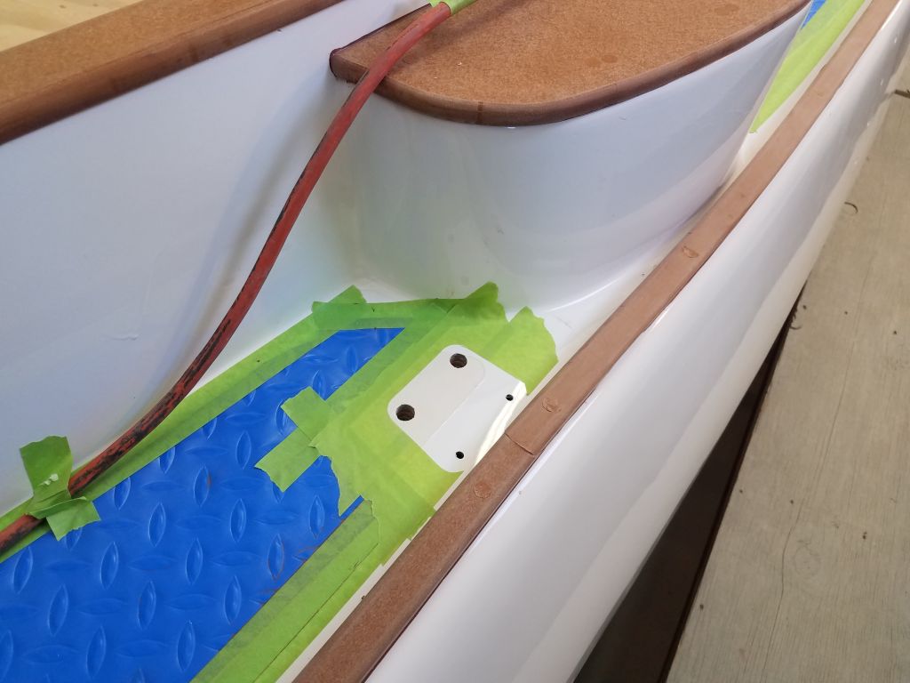
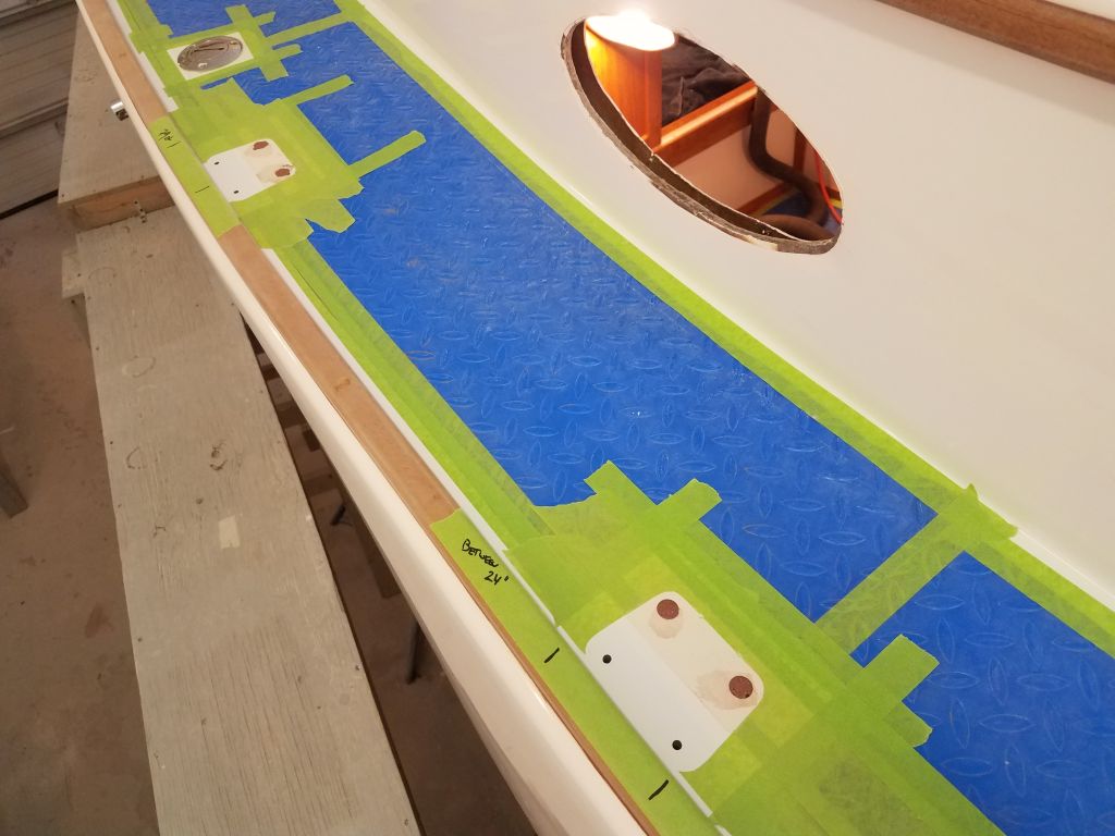
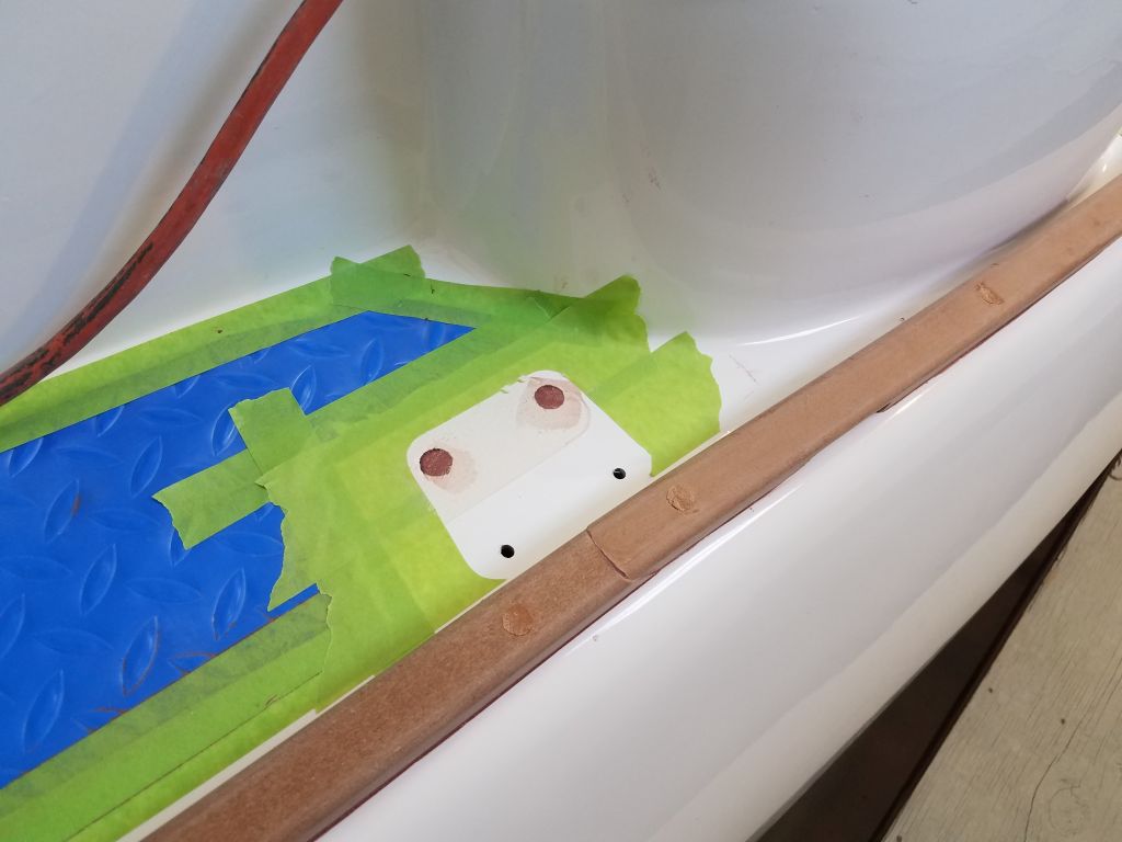
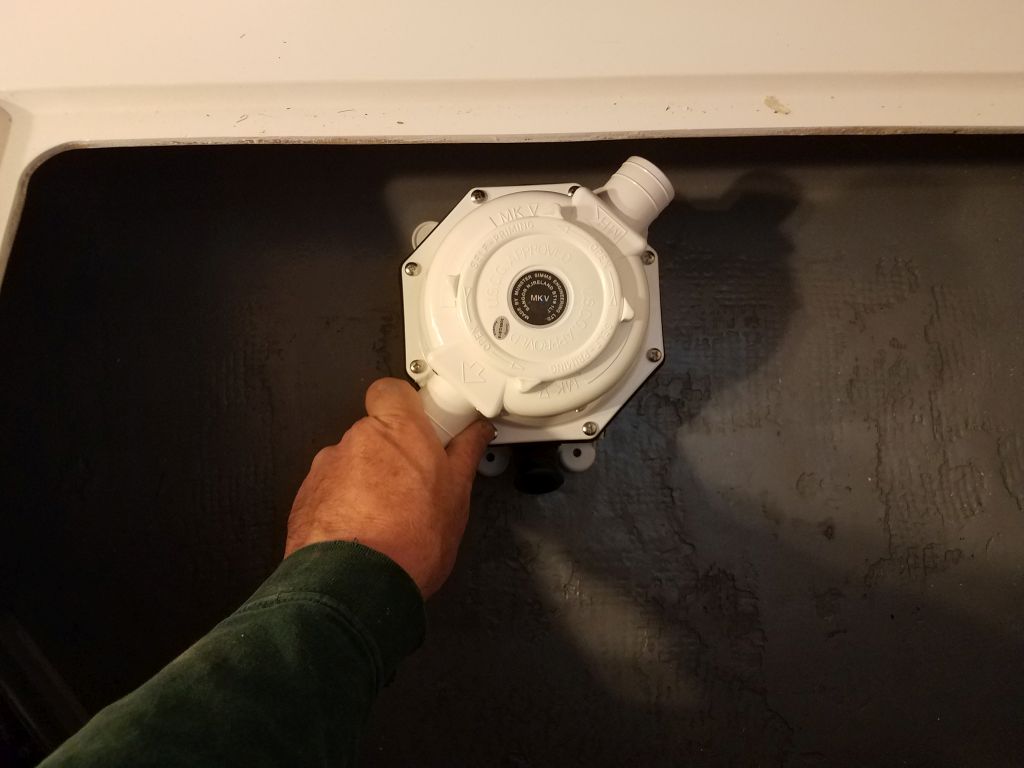
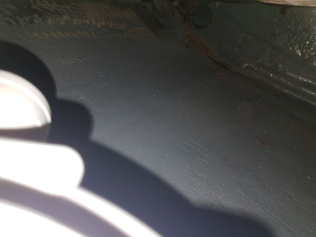
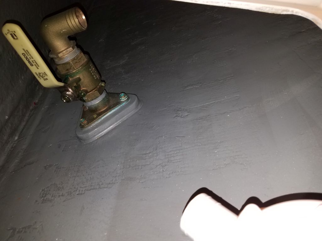
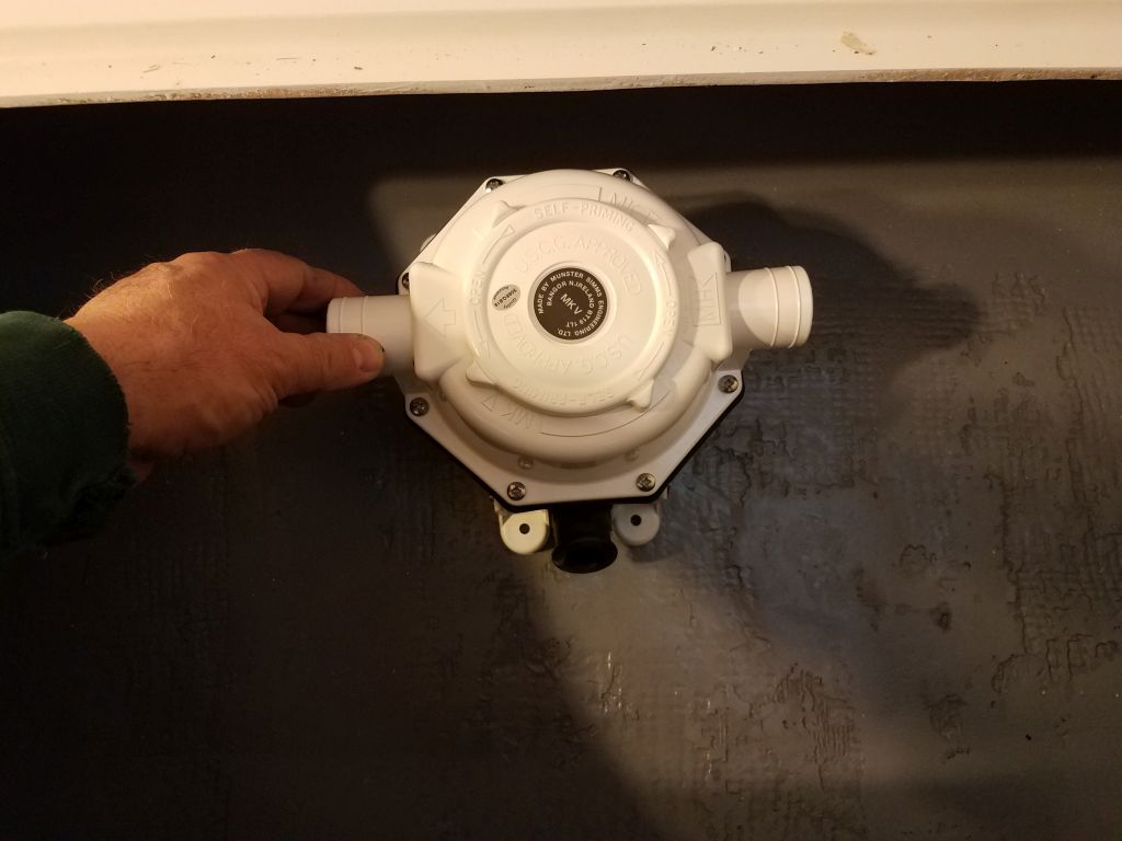
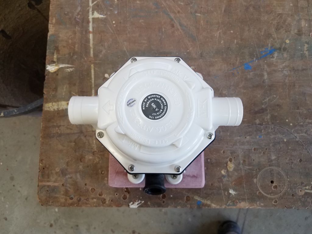
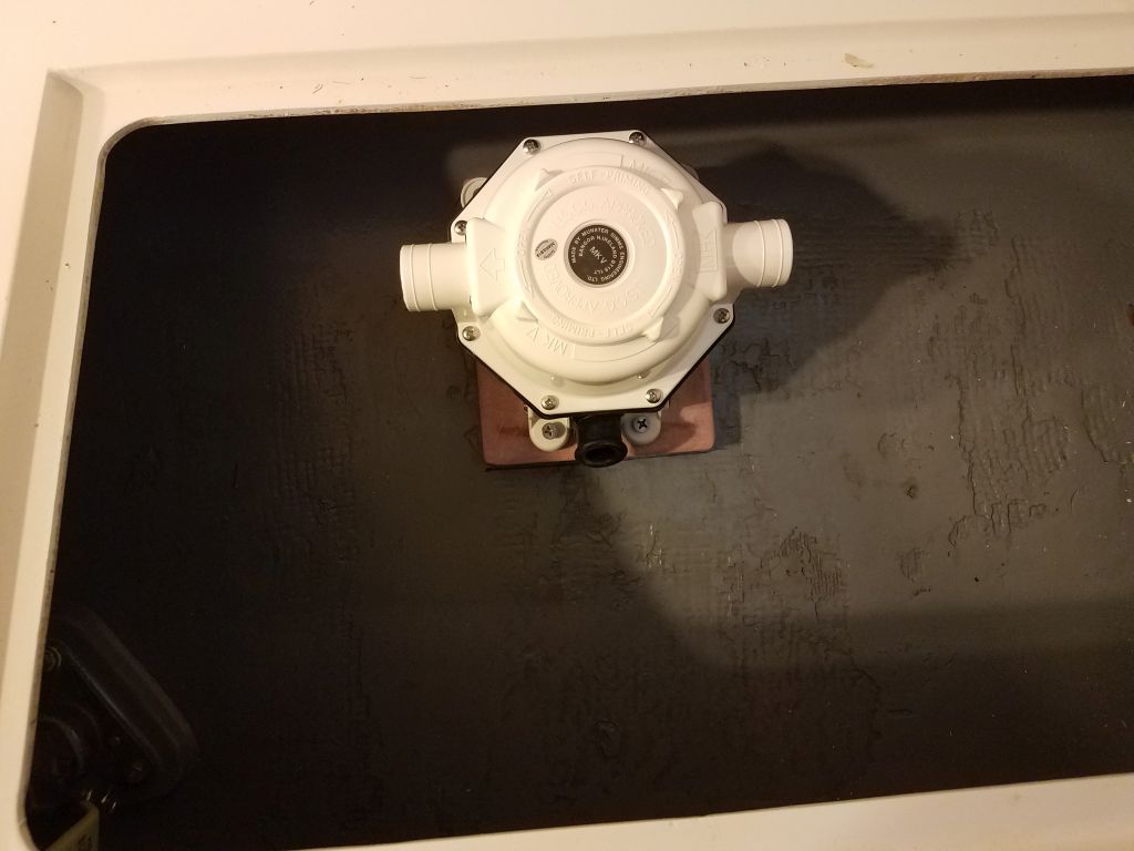
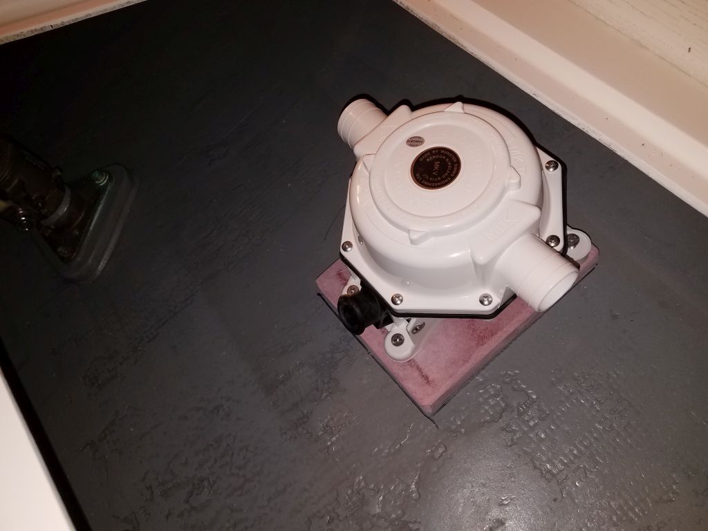
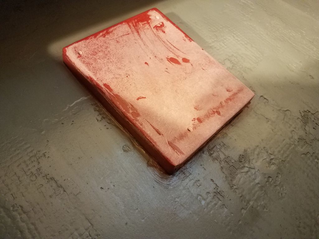
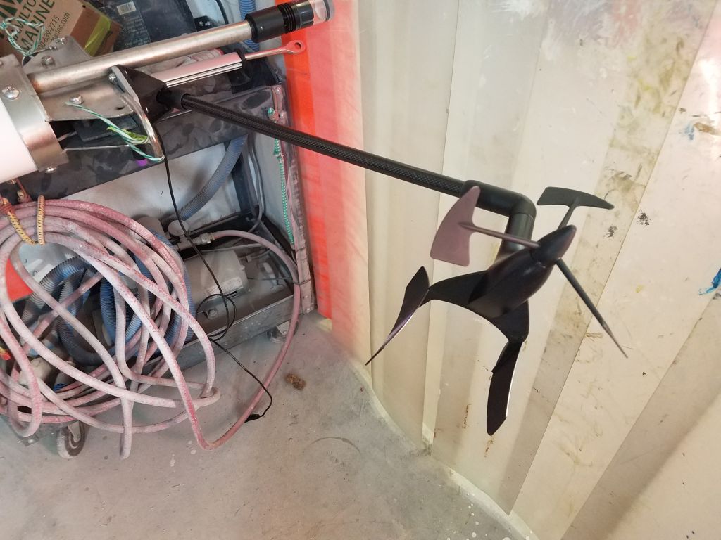
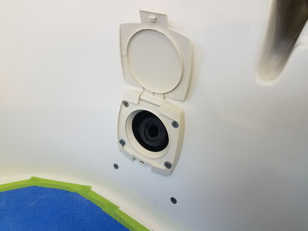
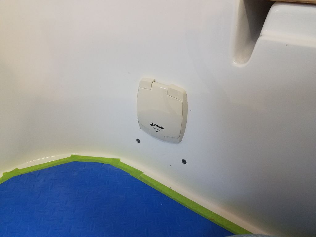
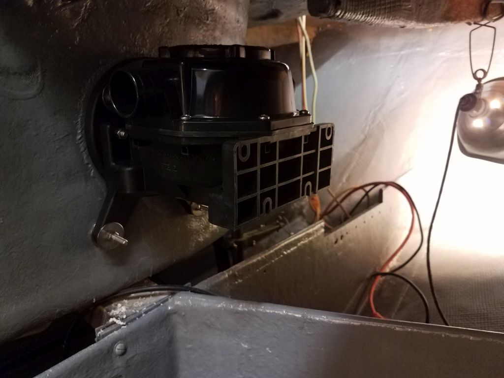
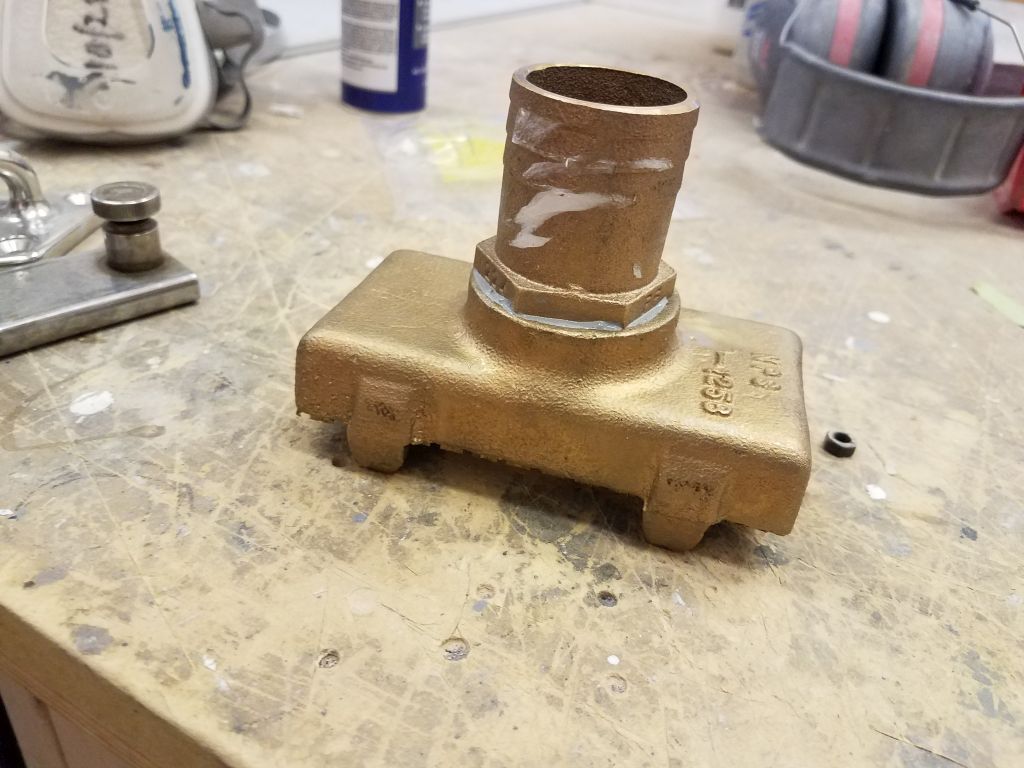
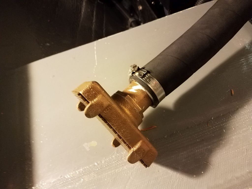
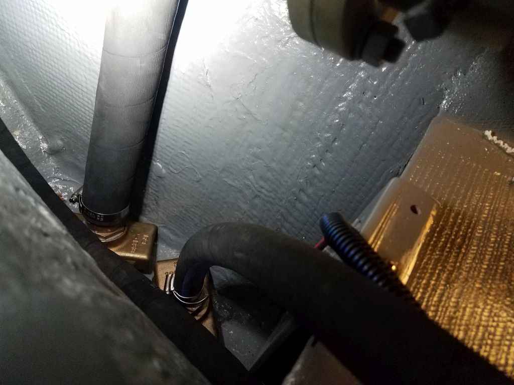
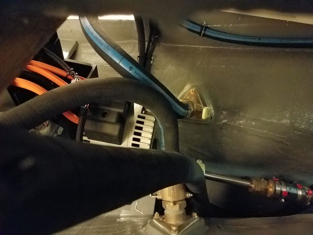
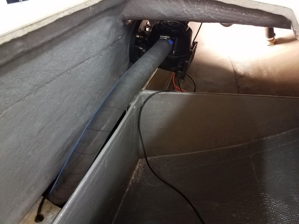
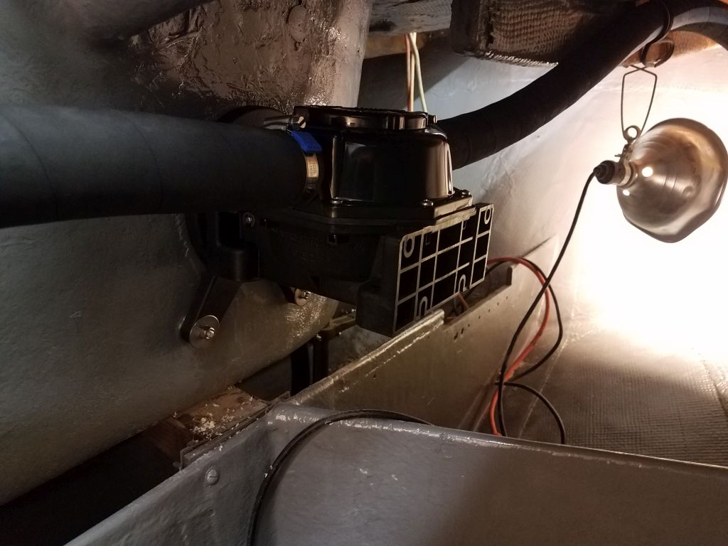
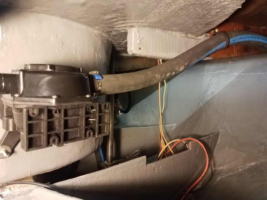
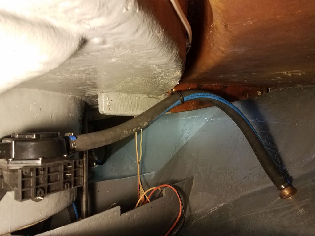
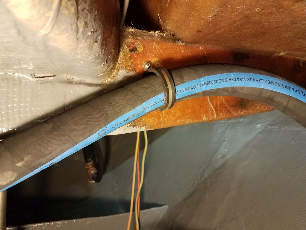
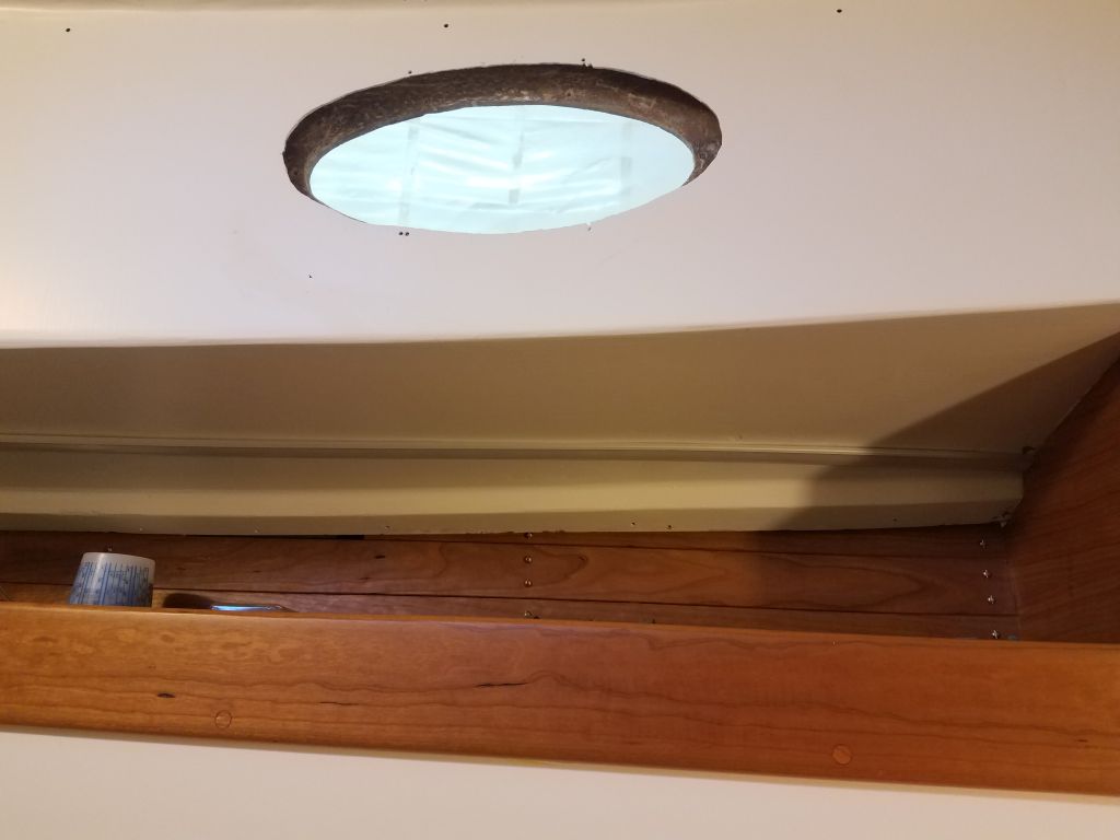
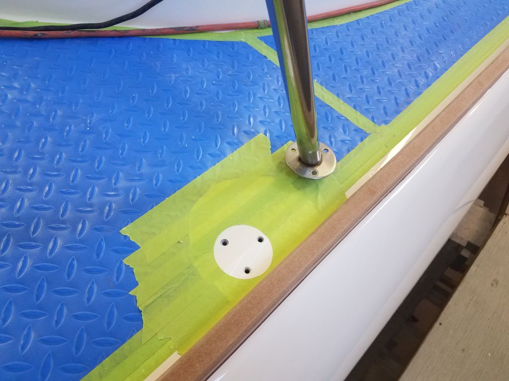
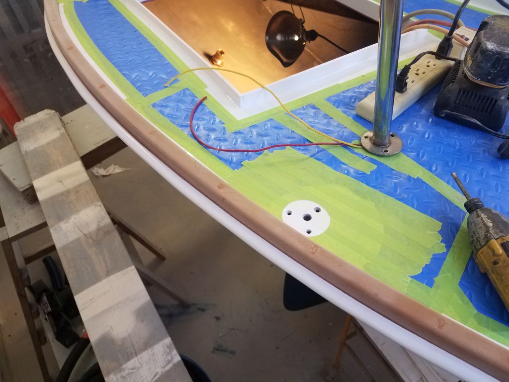
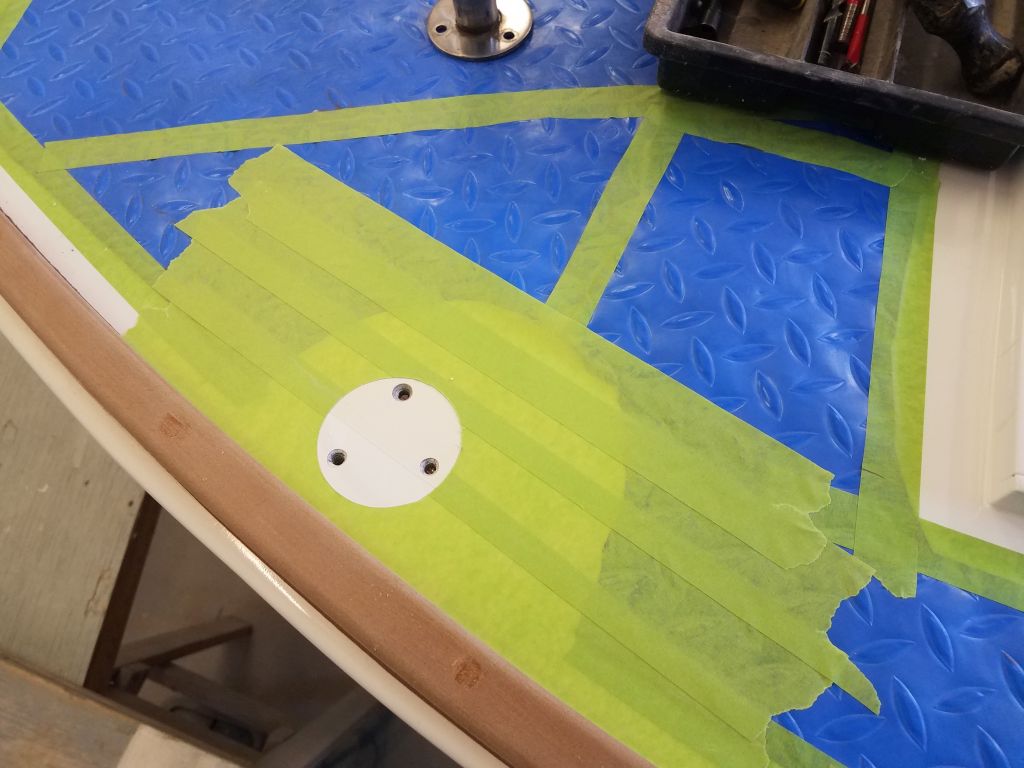
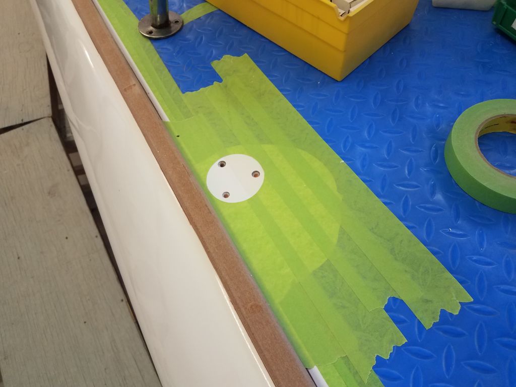
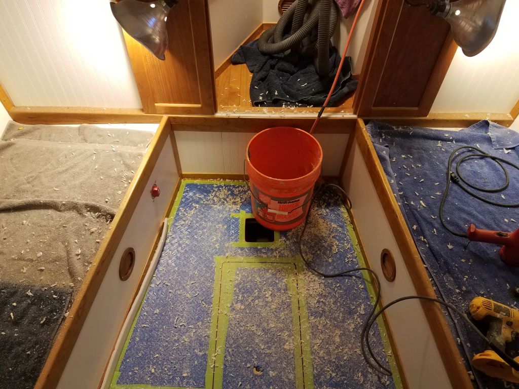
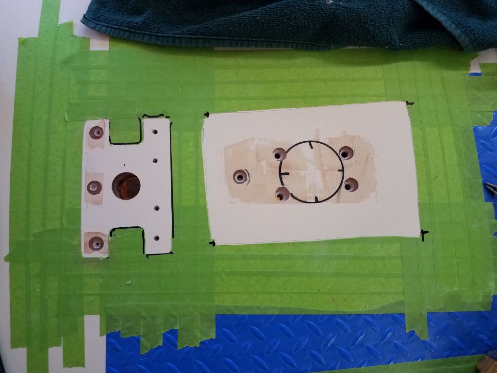
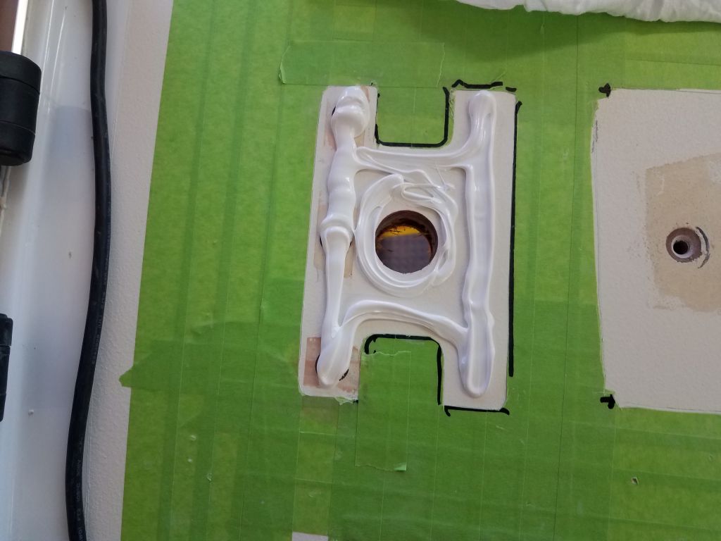
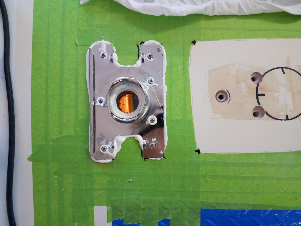
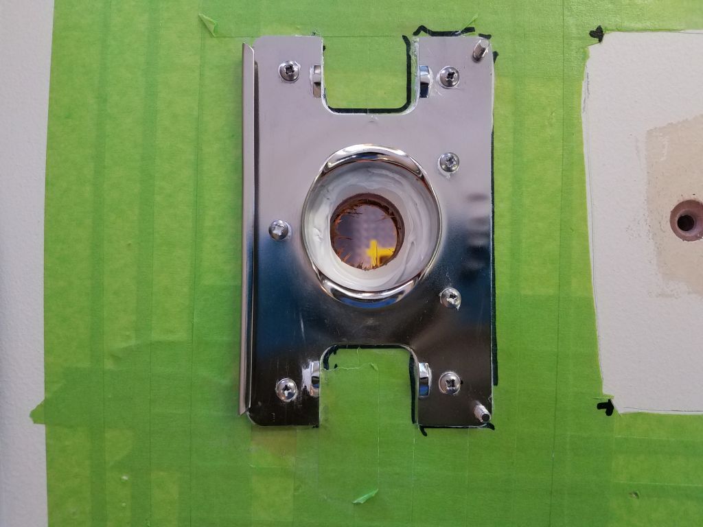
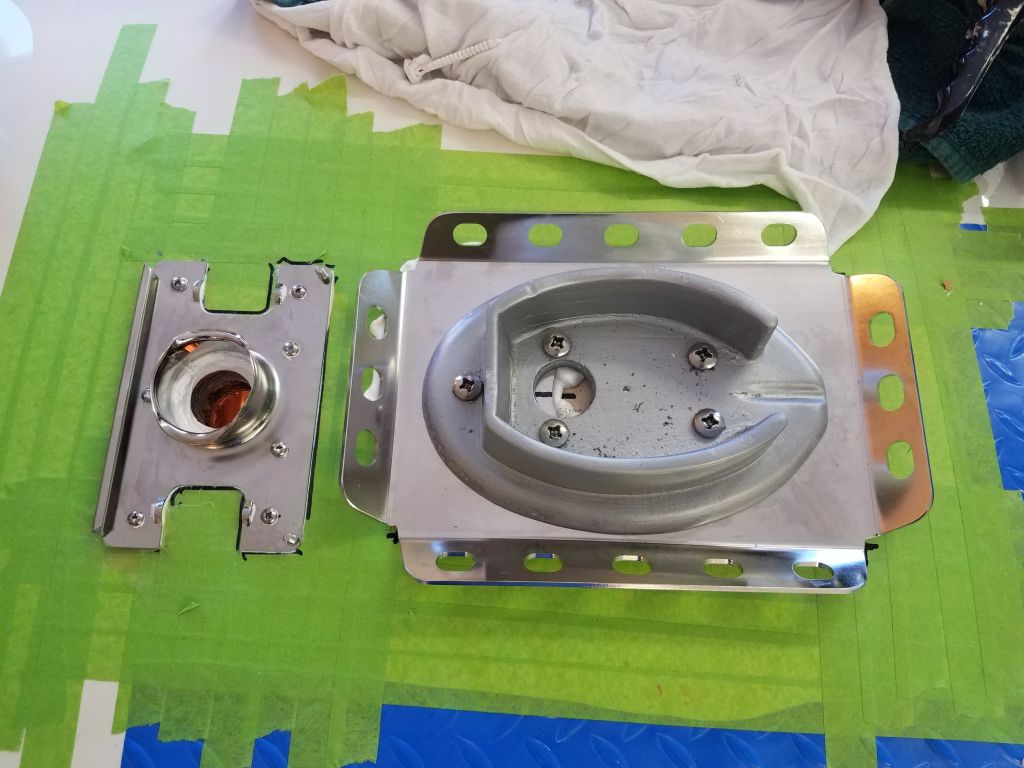
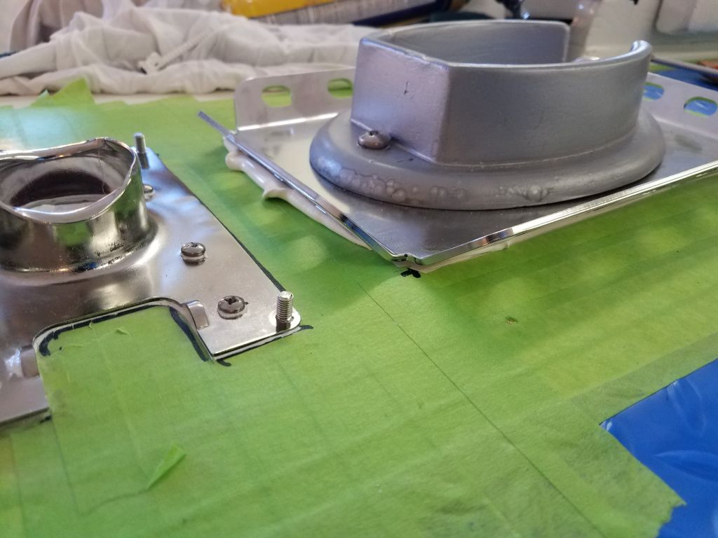
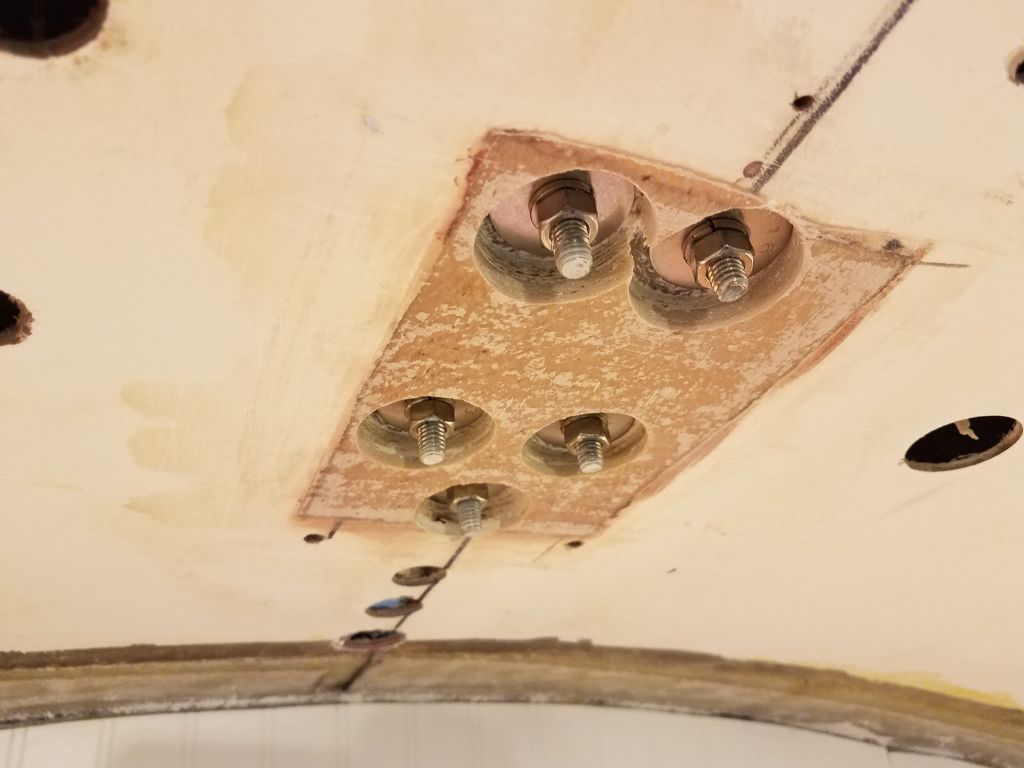
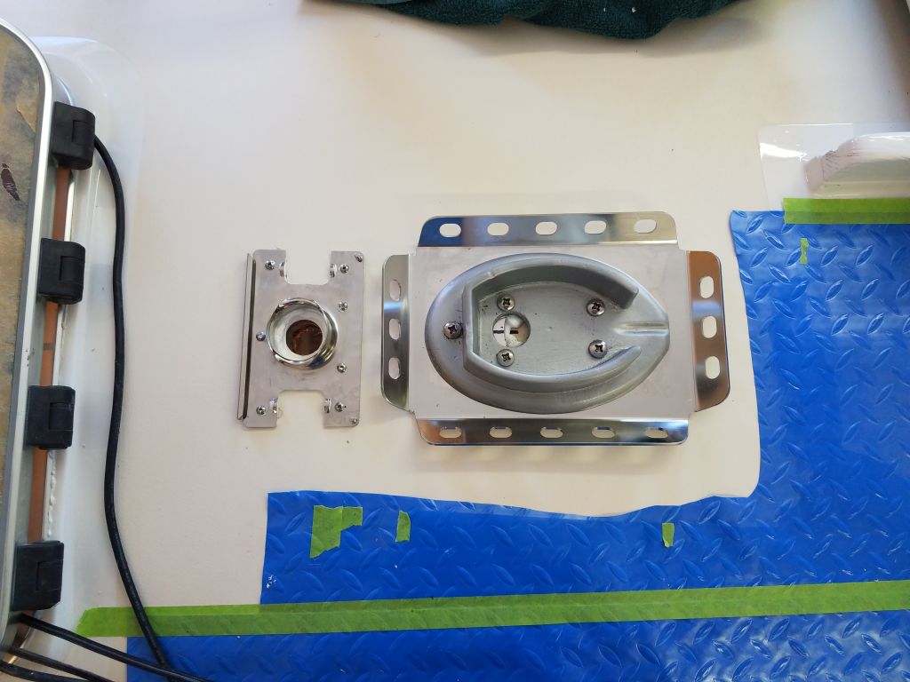
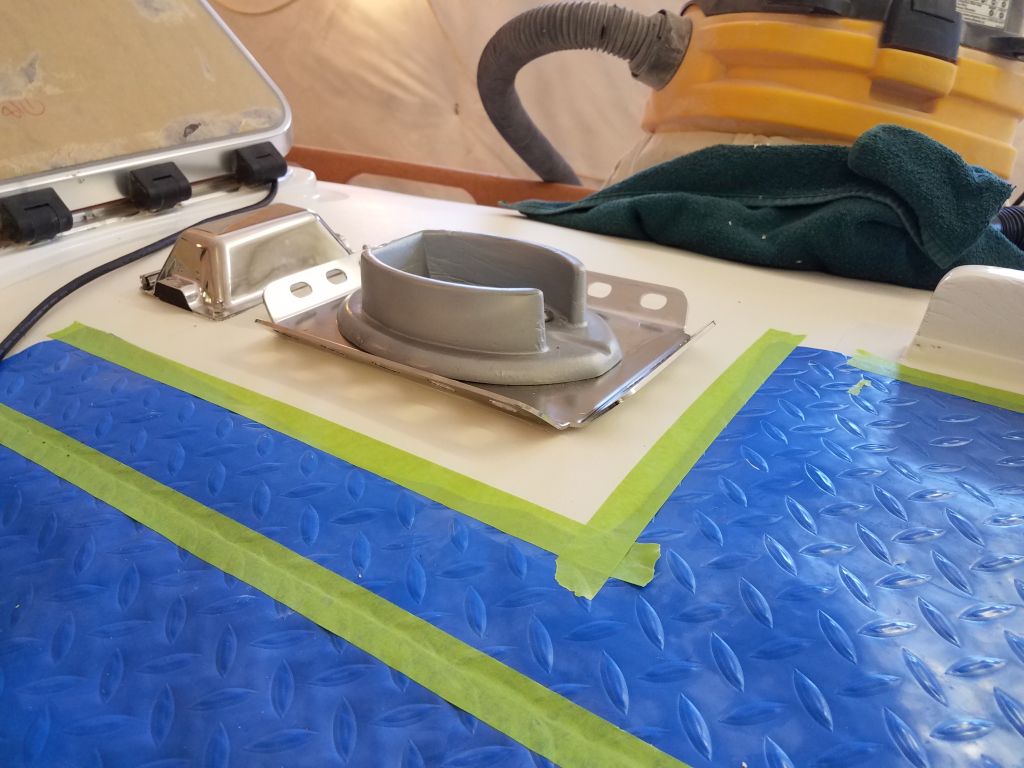
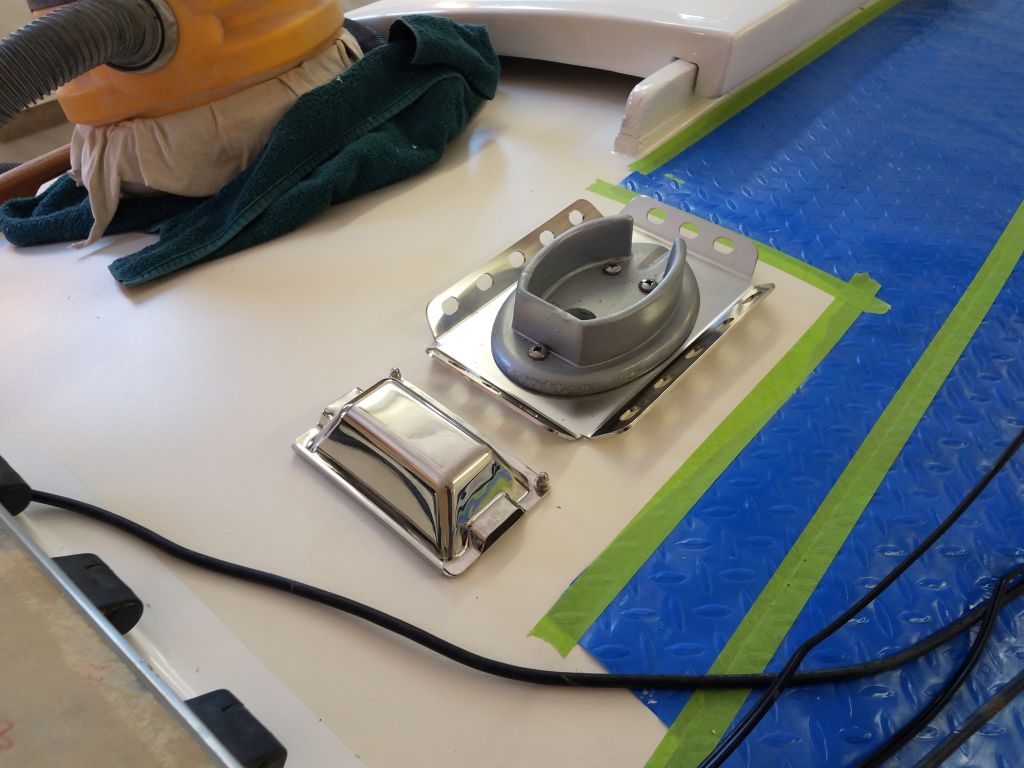
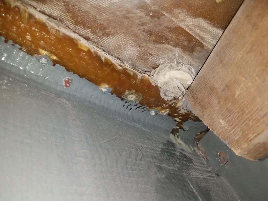
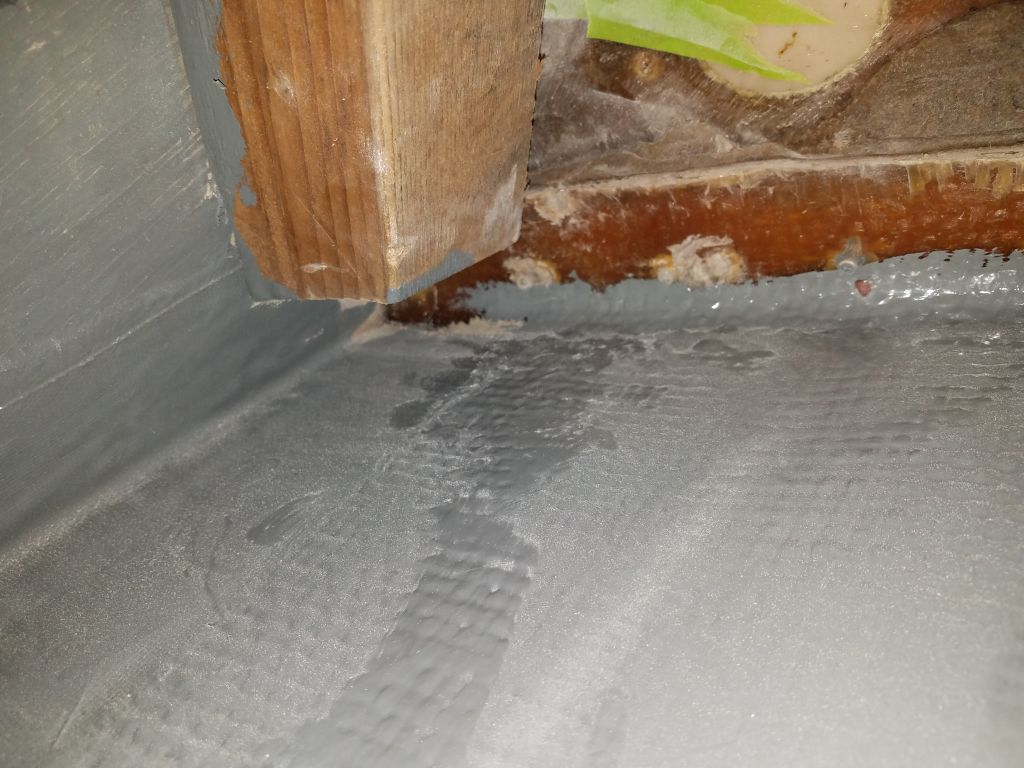
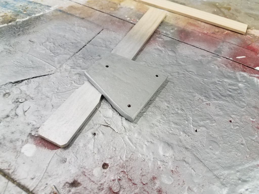
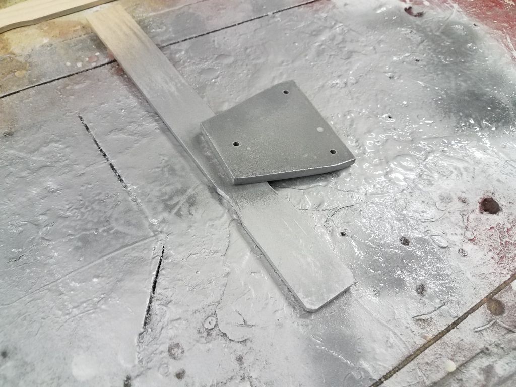
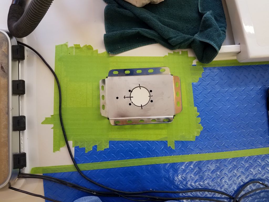
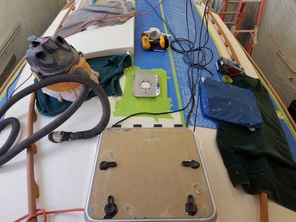
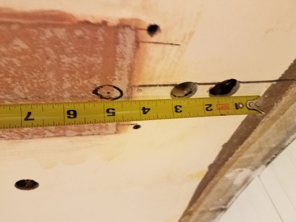
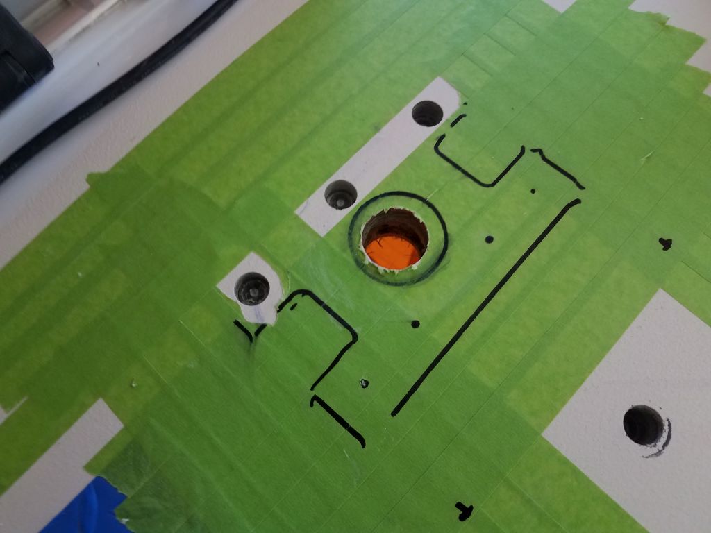
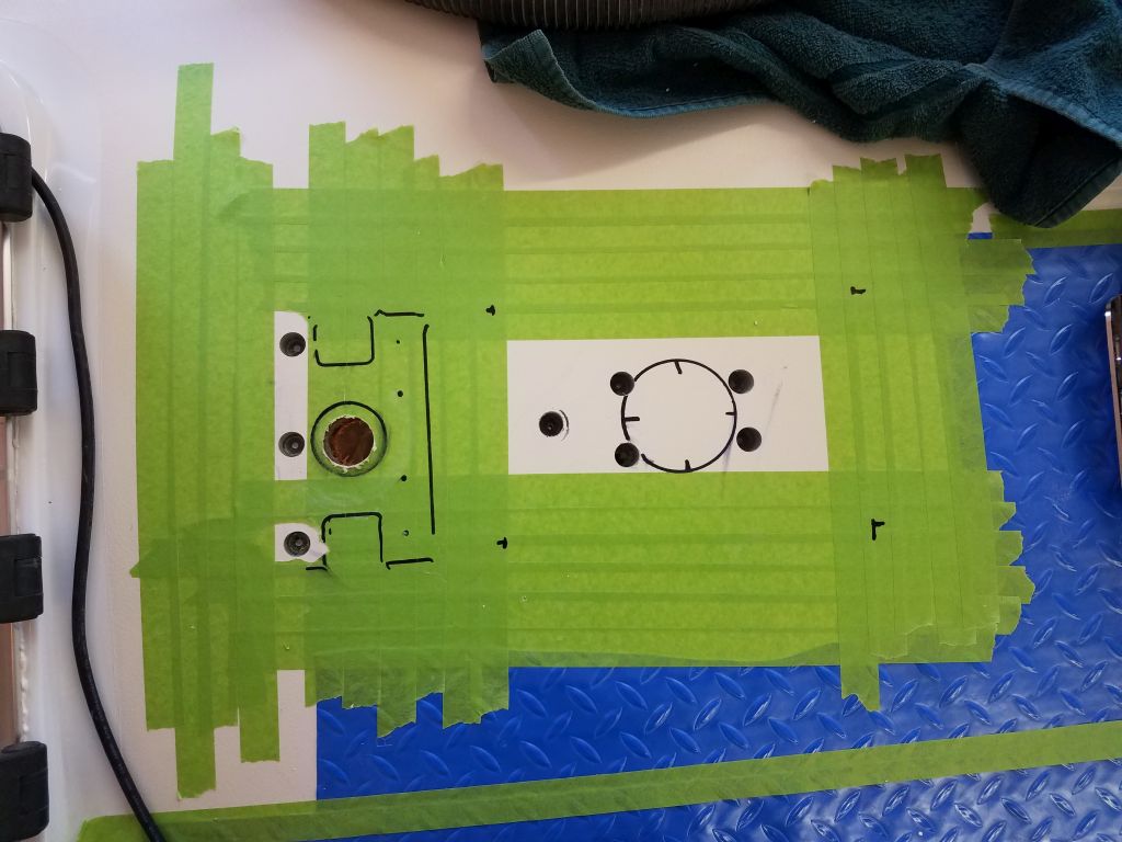
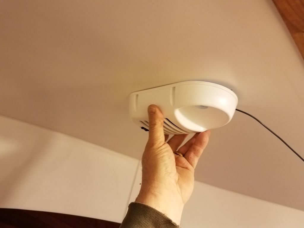
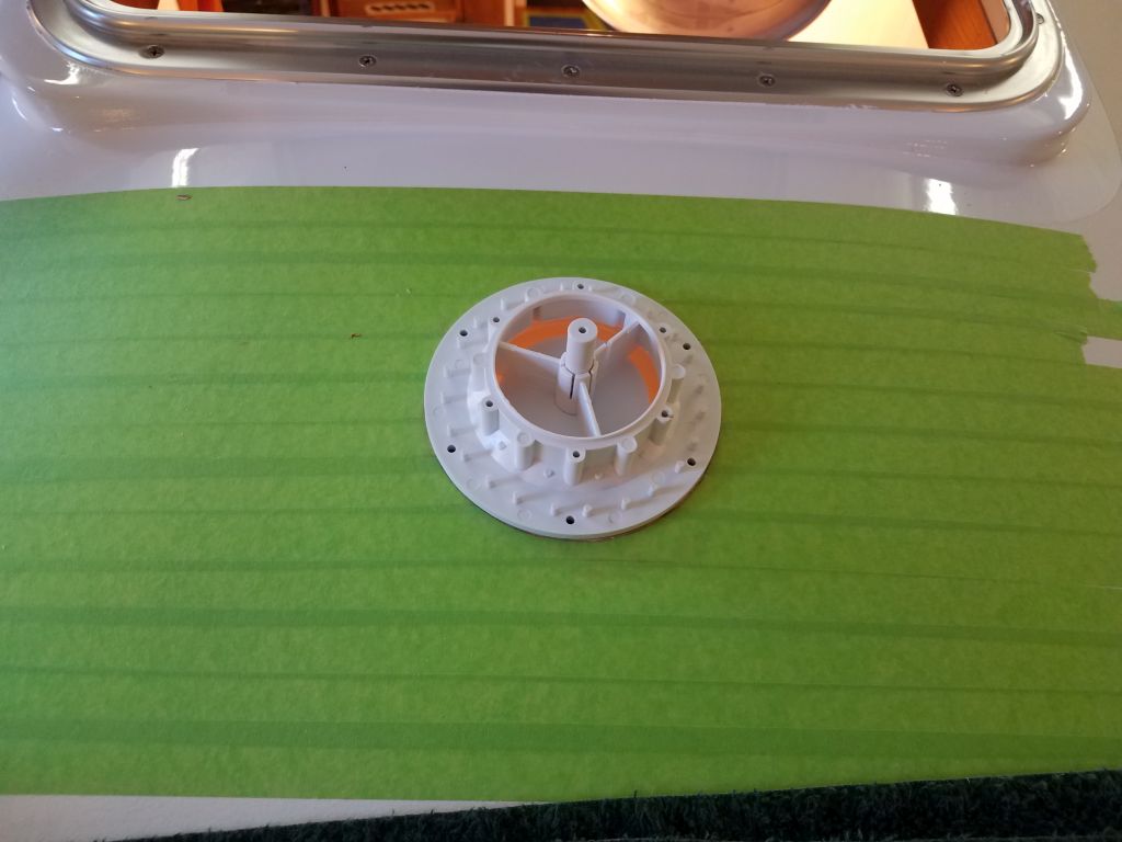
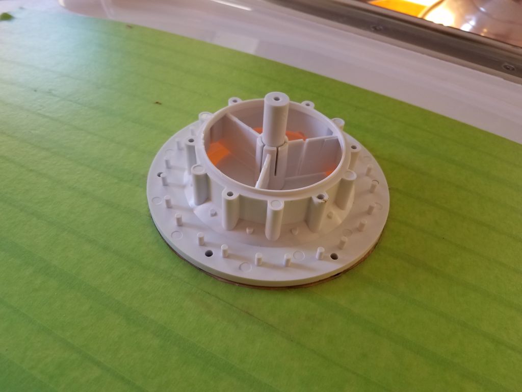
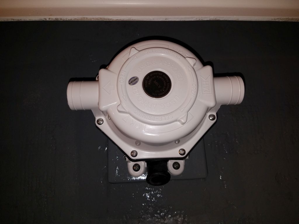
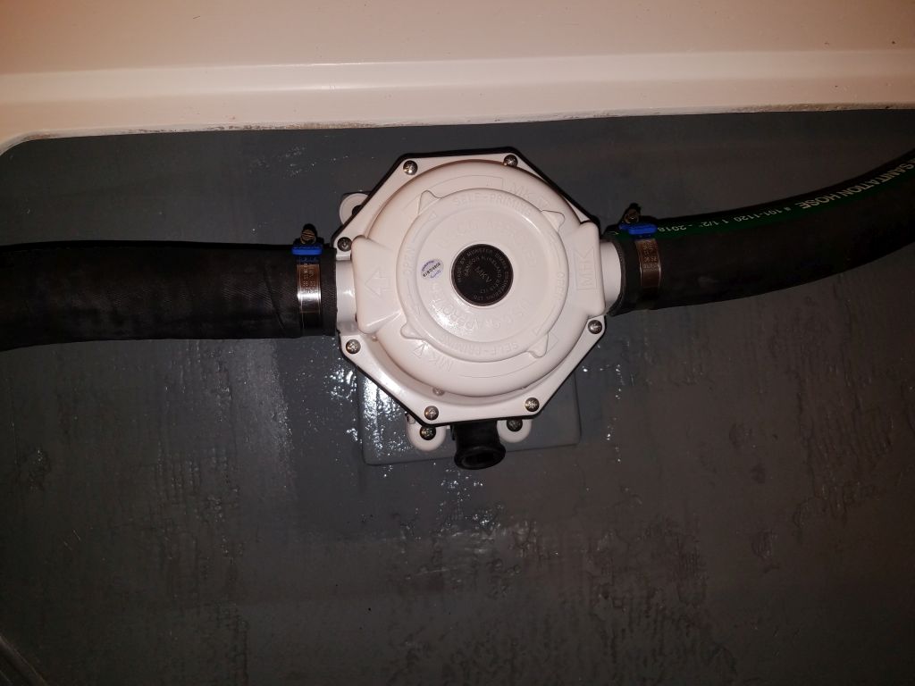
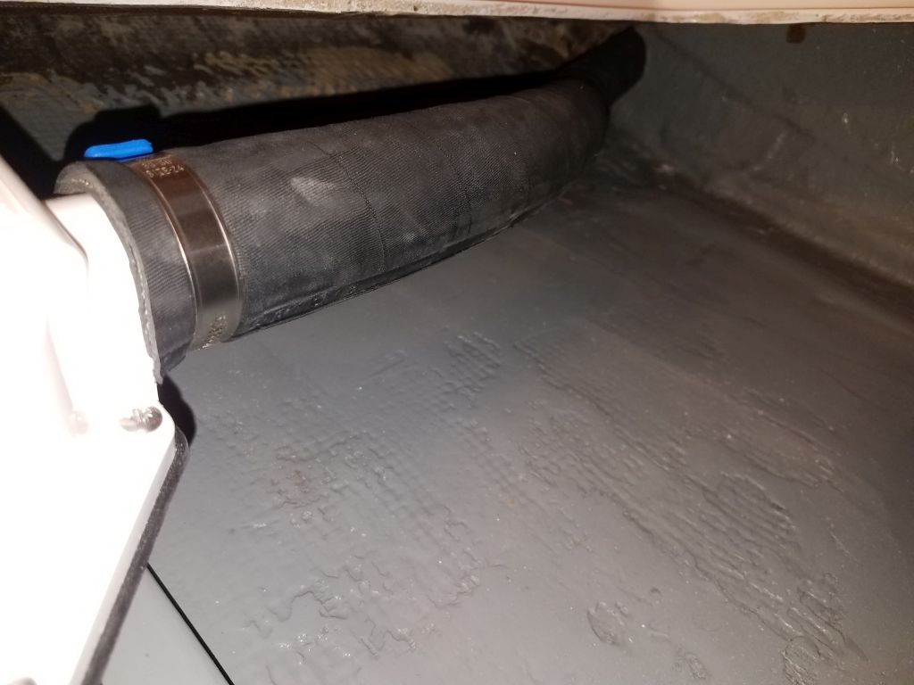
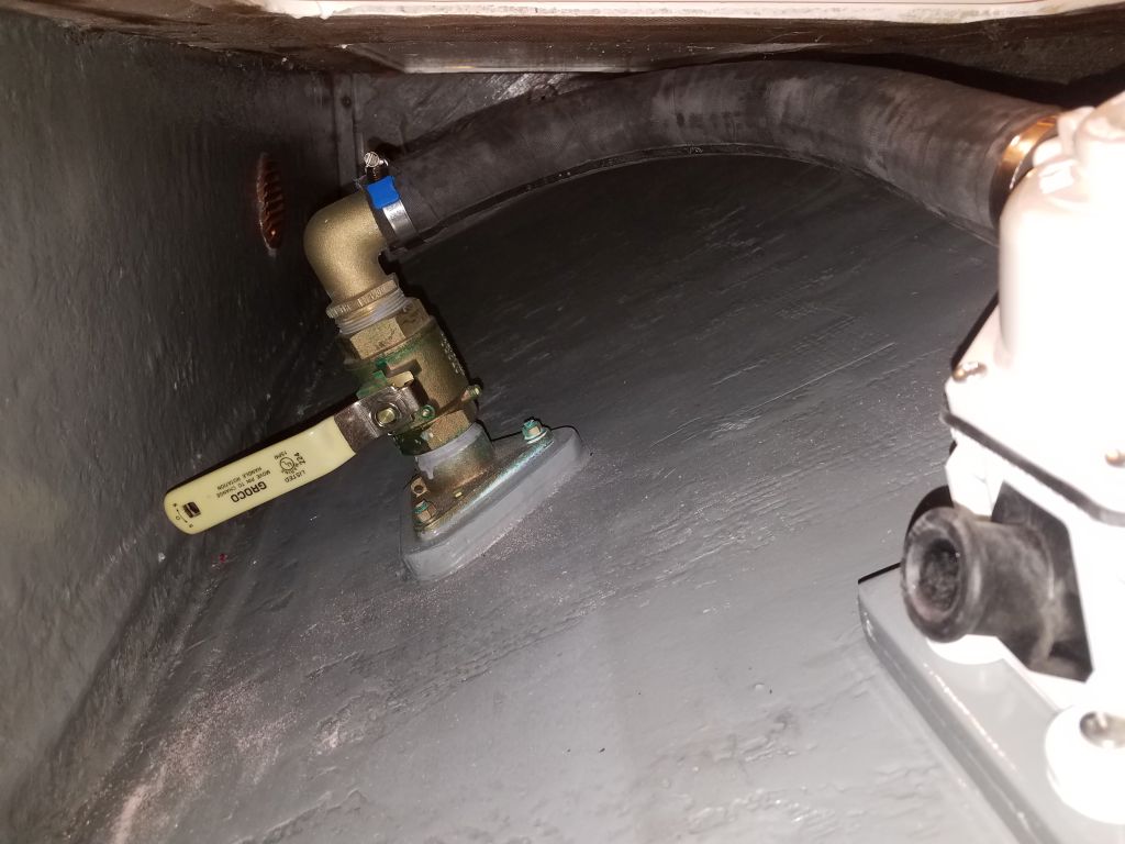
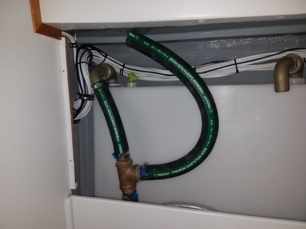
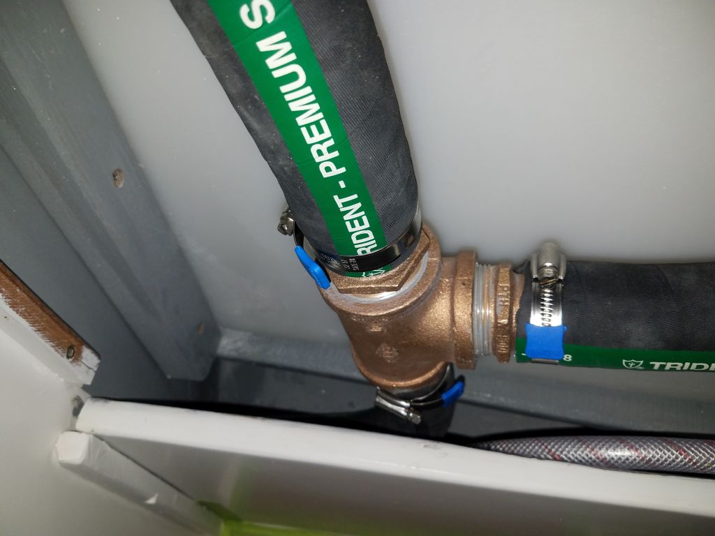
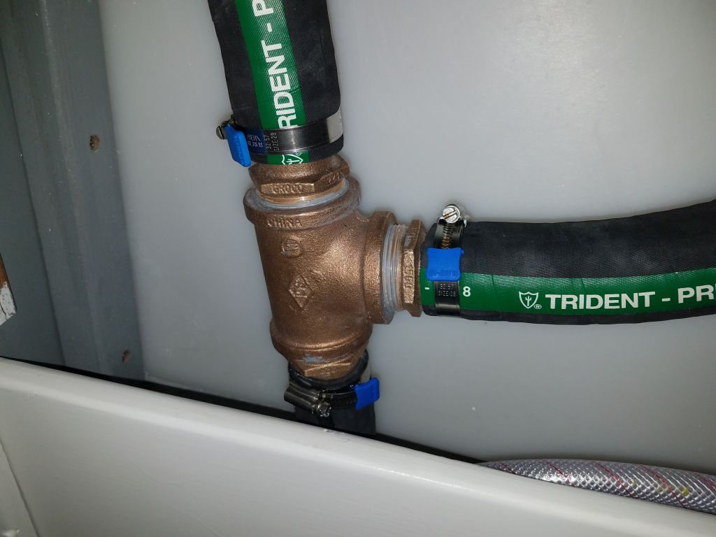
Now that the mounting block for the sanitation pump was finished, I could install the pump to the block with four machine screws. Afterwards, I installed the sanitation hose to and from the pump, including a junction inside the holding tank locker to allow the waste from the tank to exit either overboard through the new pump (where legal), or to a shoreside facility through a deck fitting. I used the length of hose leading to the deck to mark where the deck fitting should go, and drilled a pilot hole from beneath to mark the location from above.
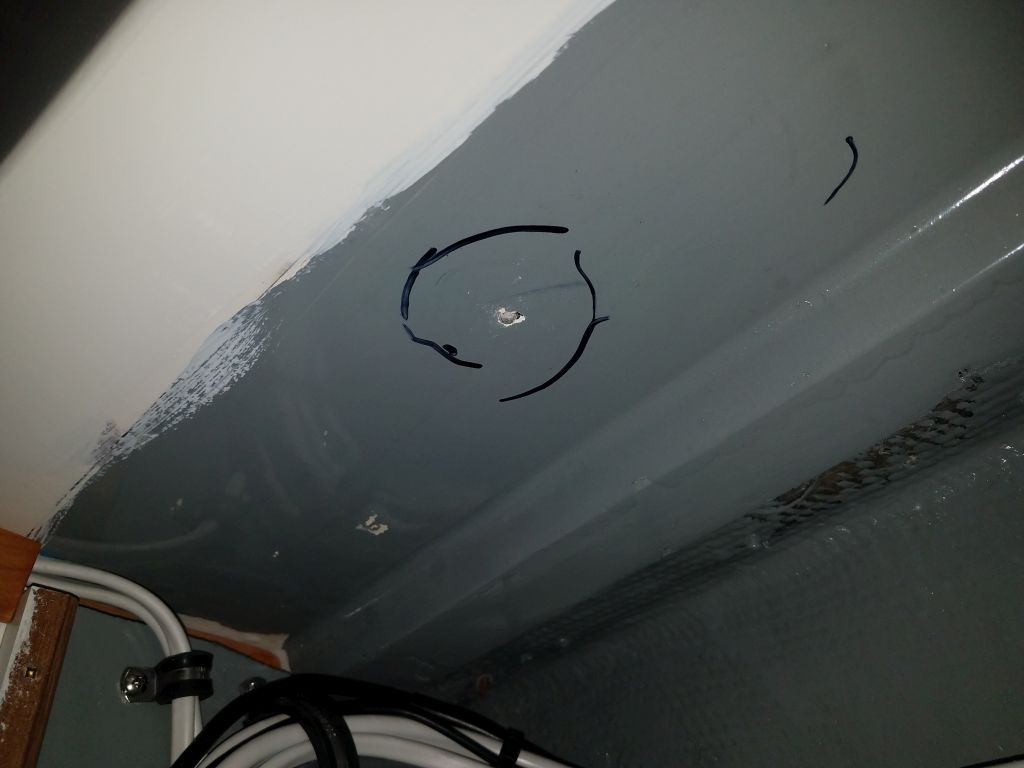
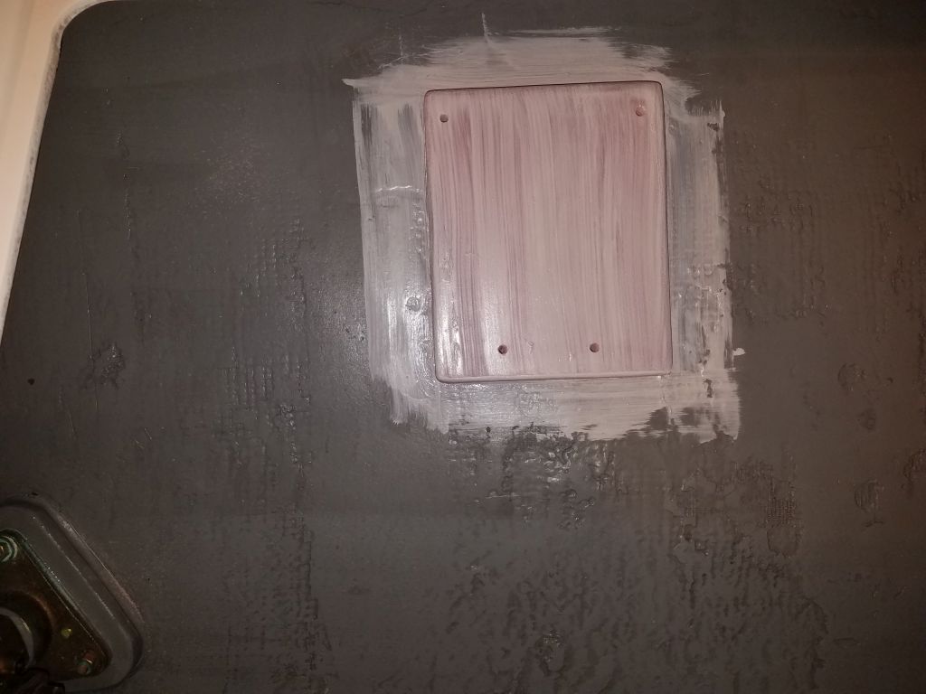
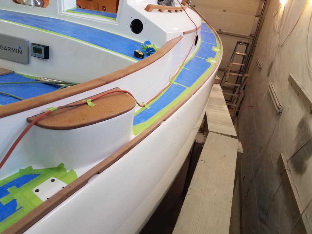
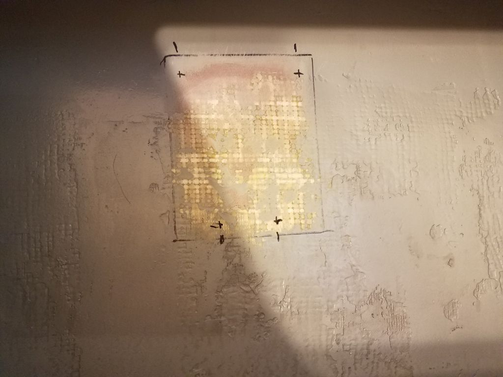
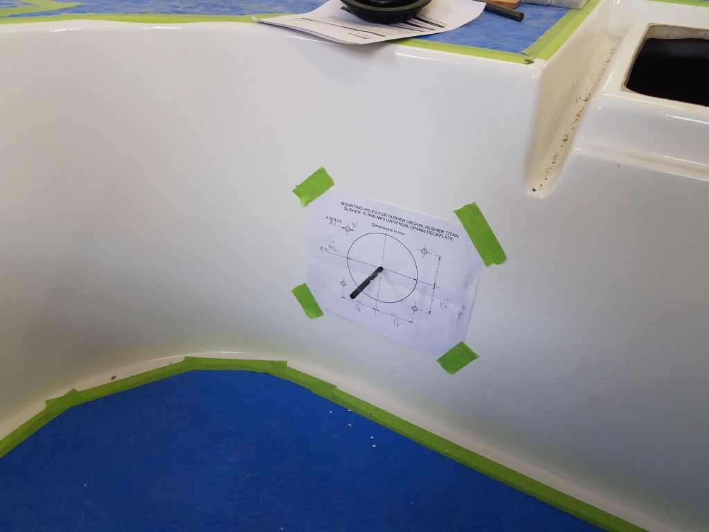
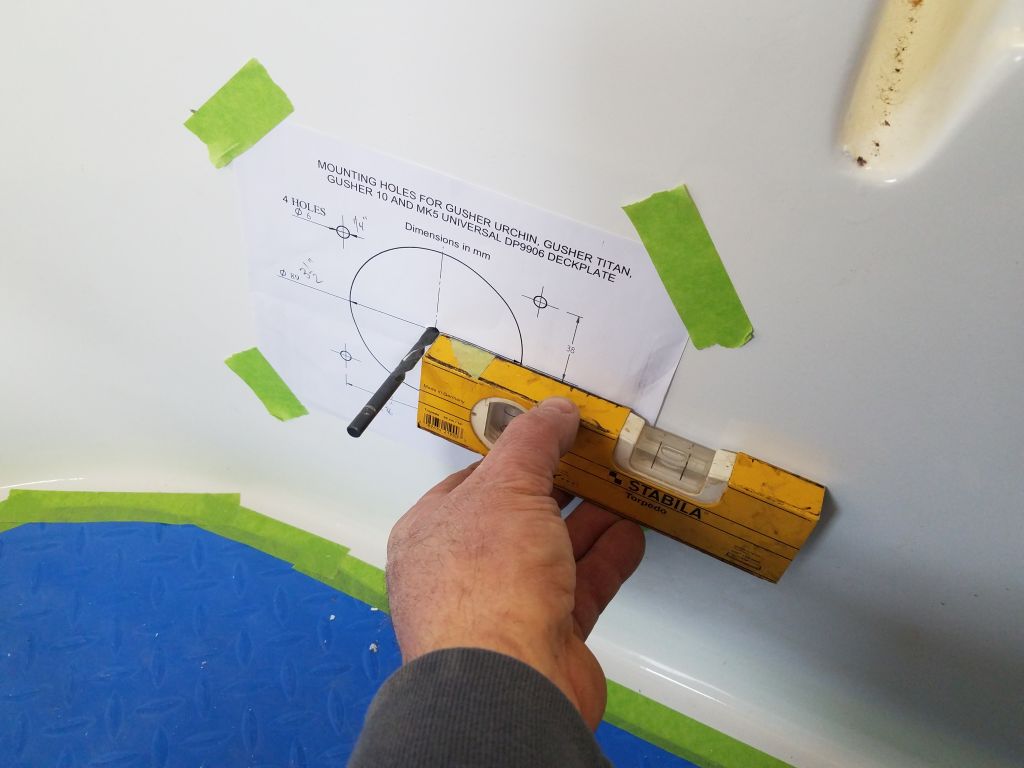
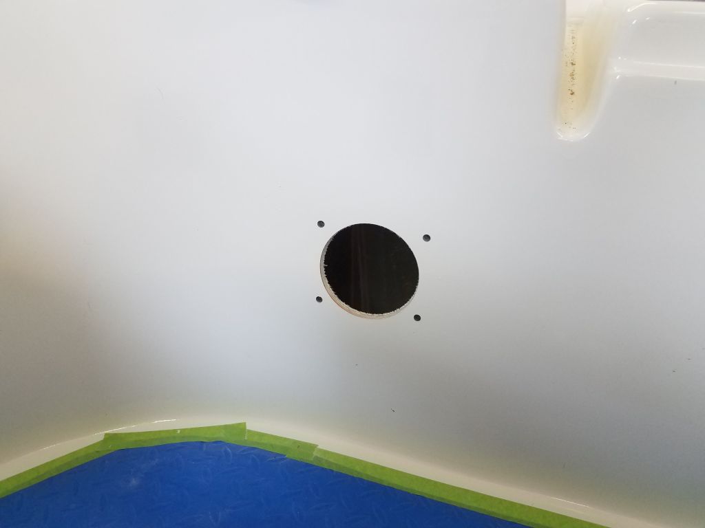
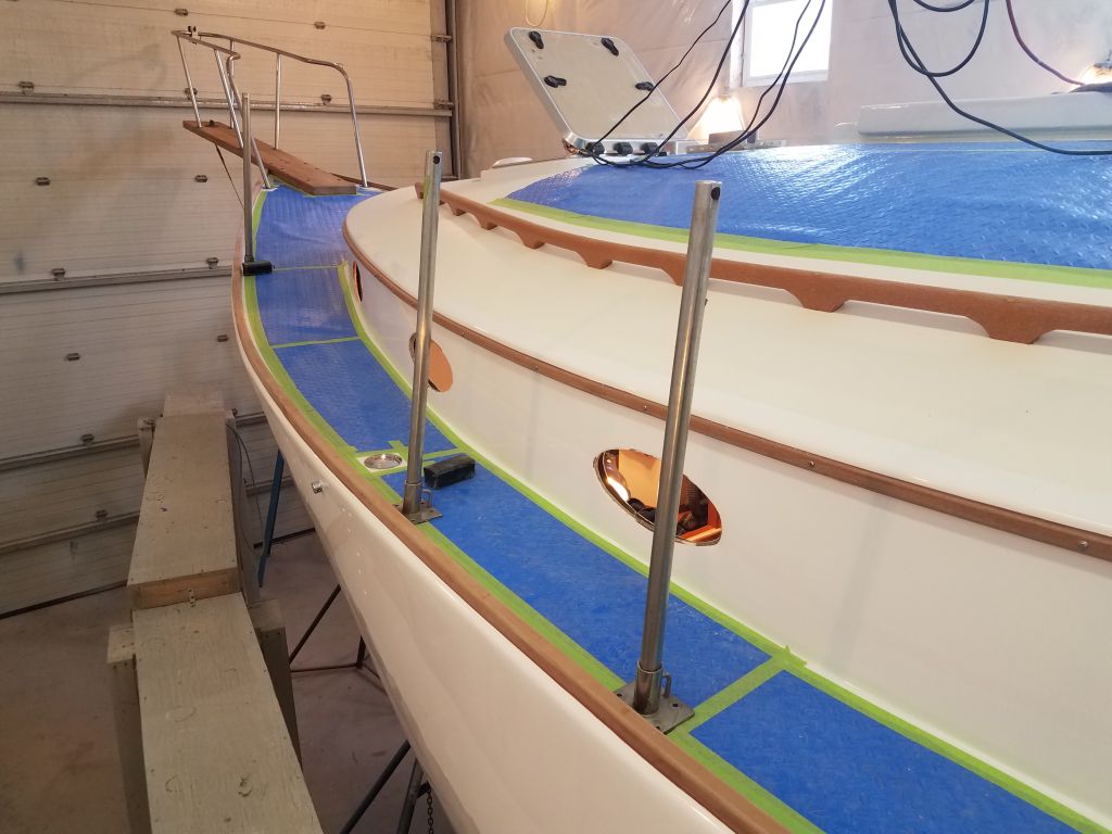
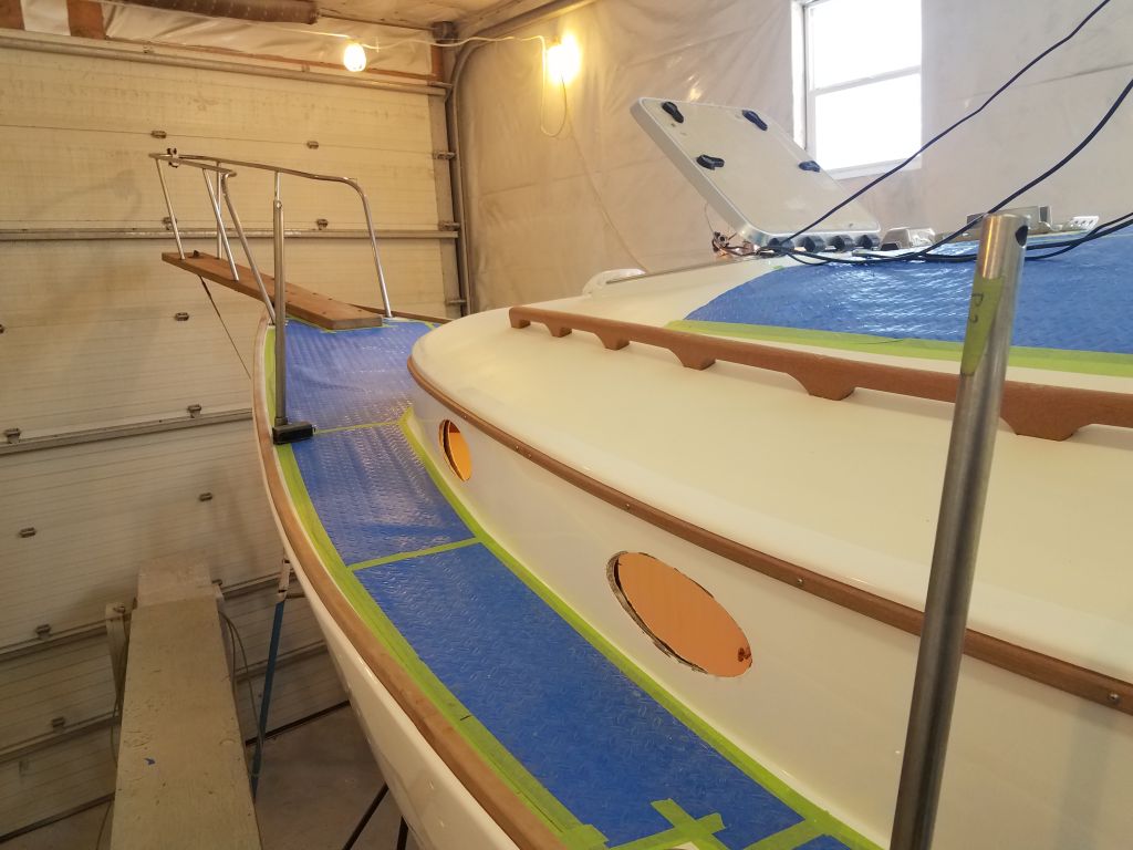
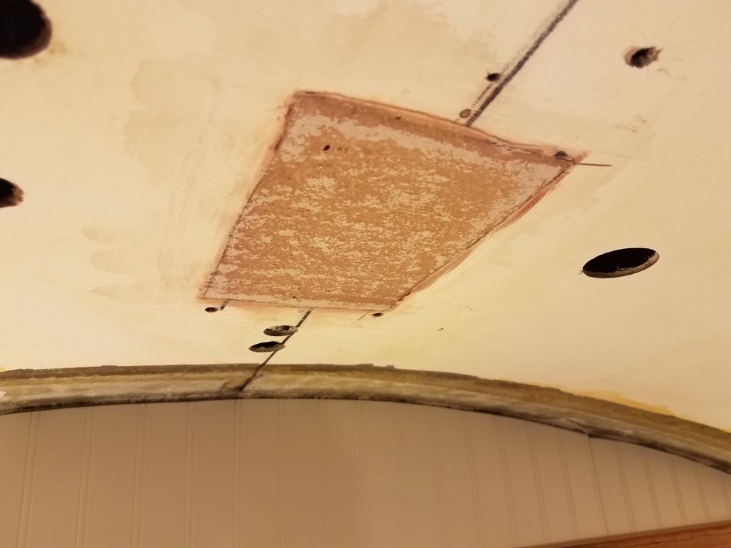
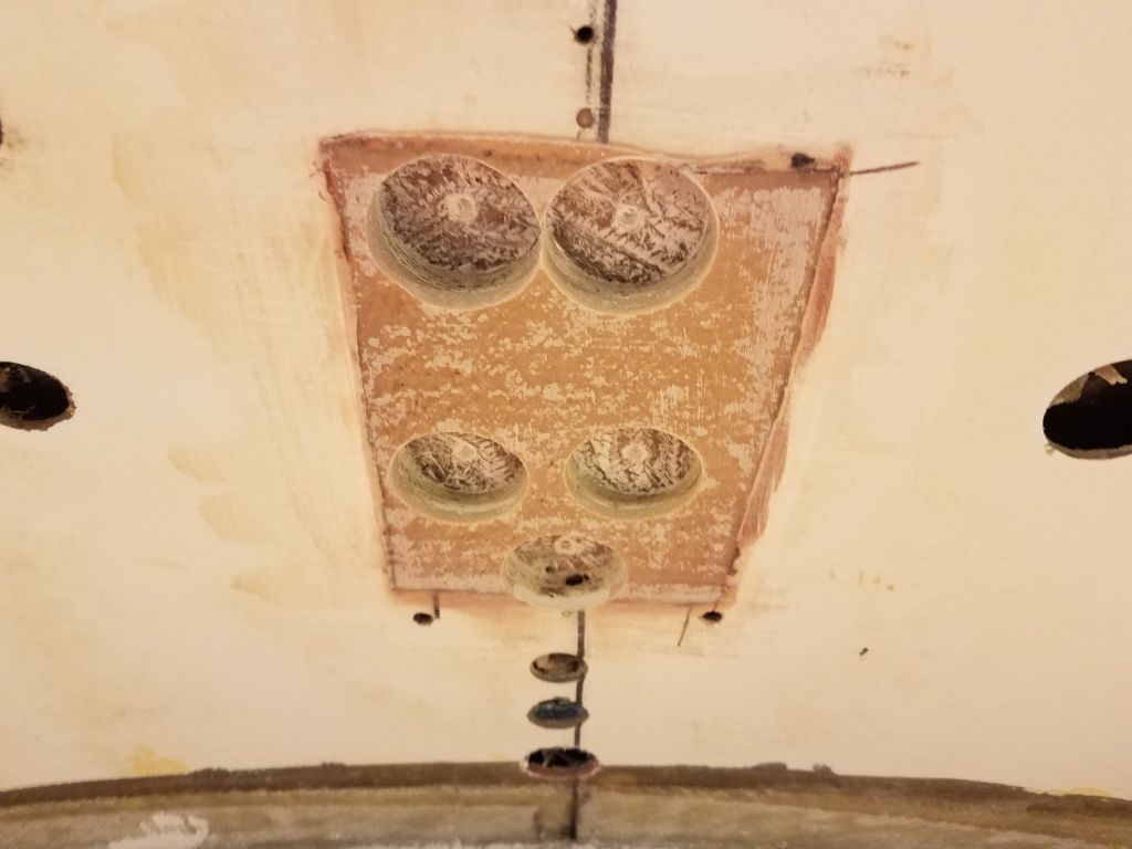
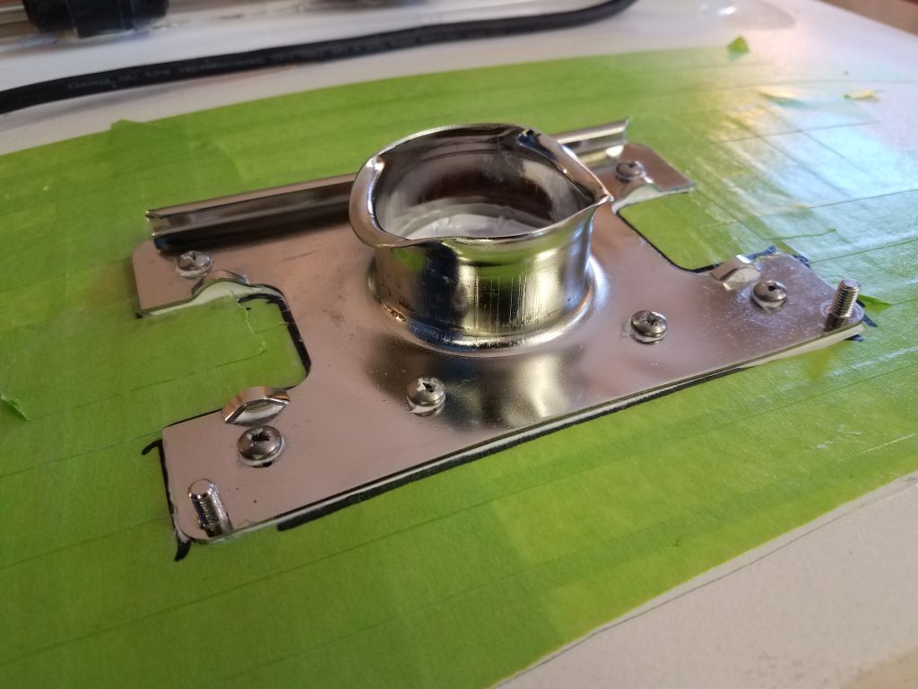
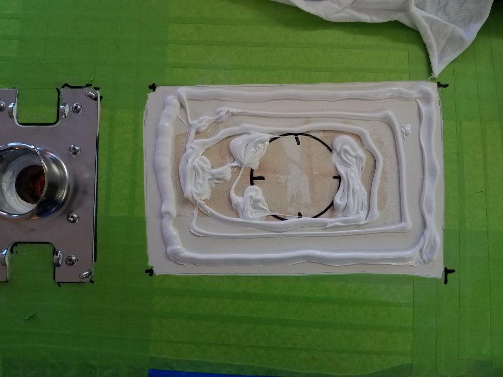
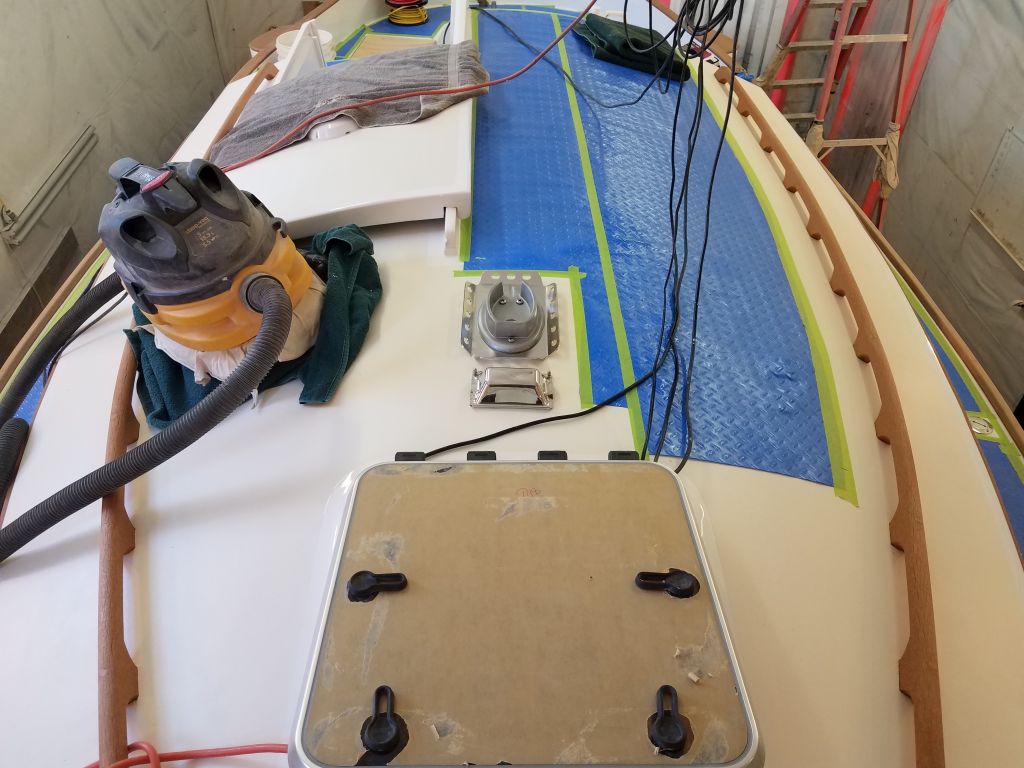
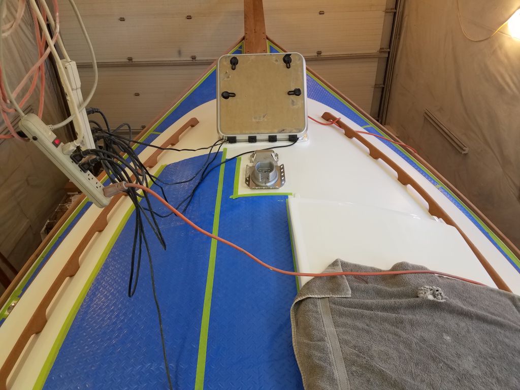
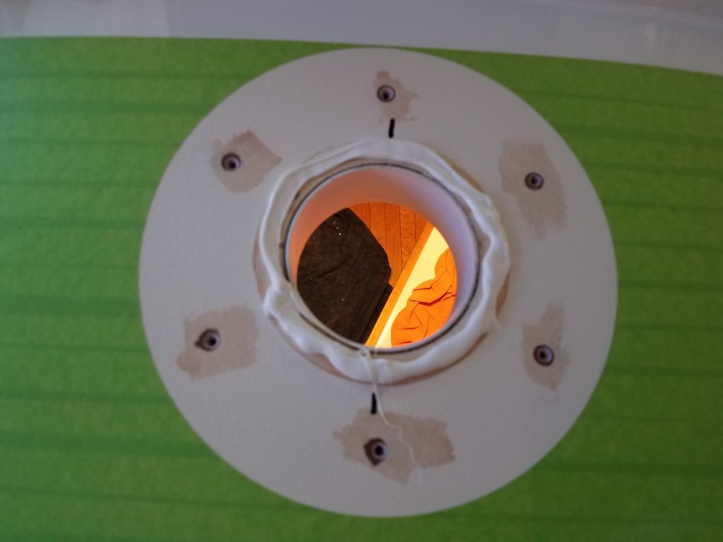
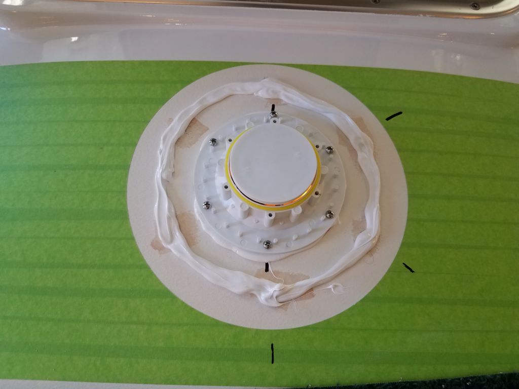
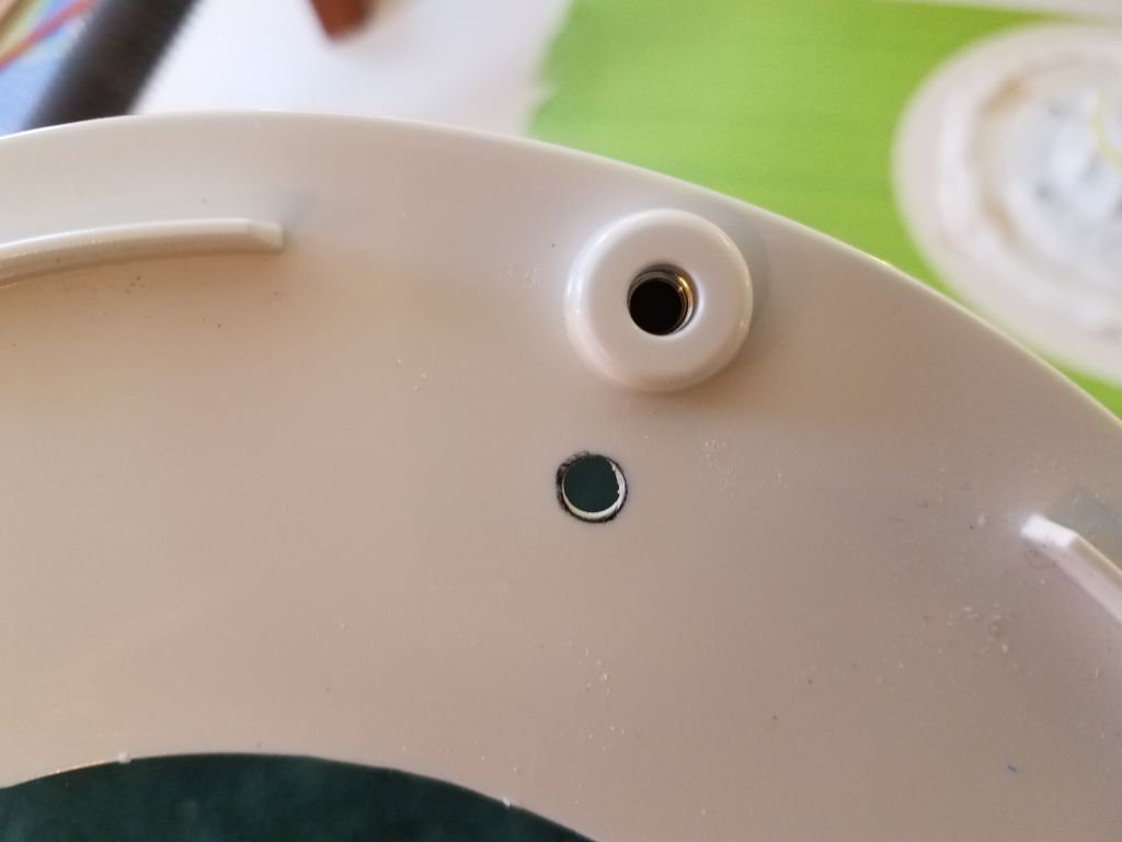
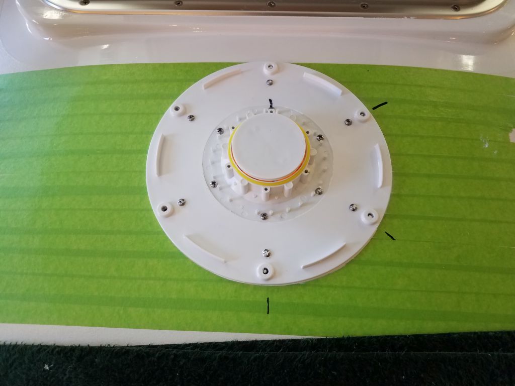
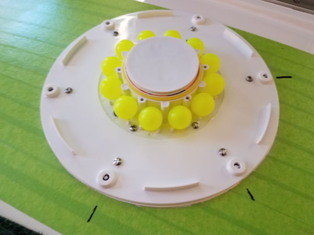
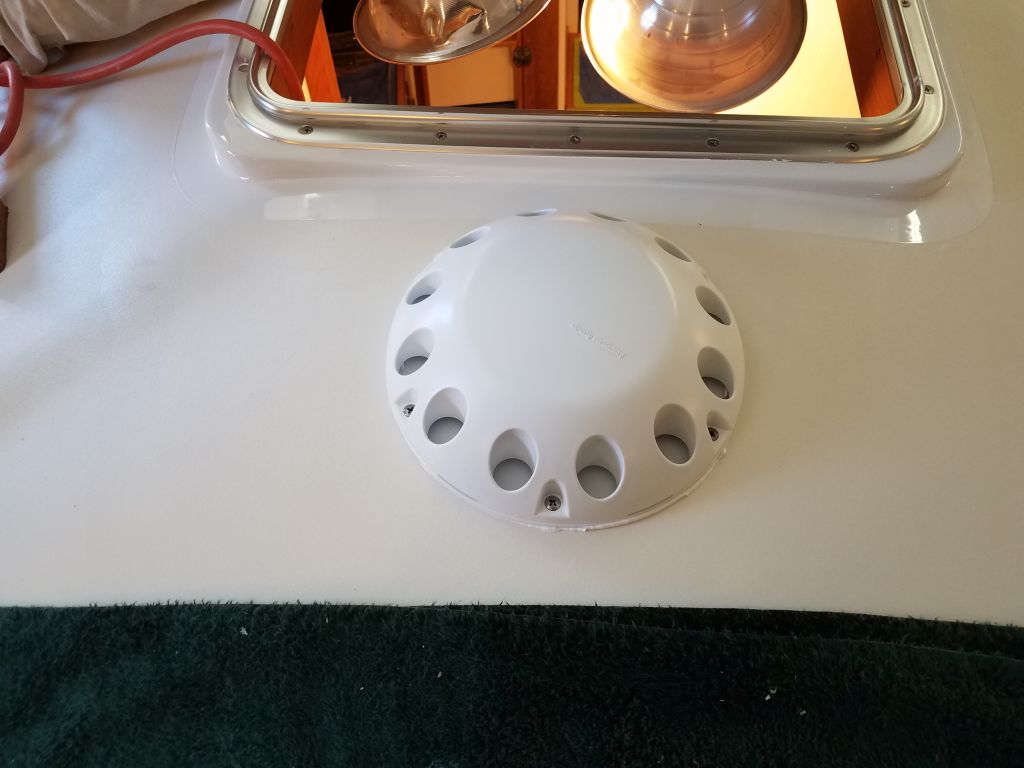
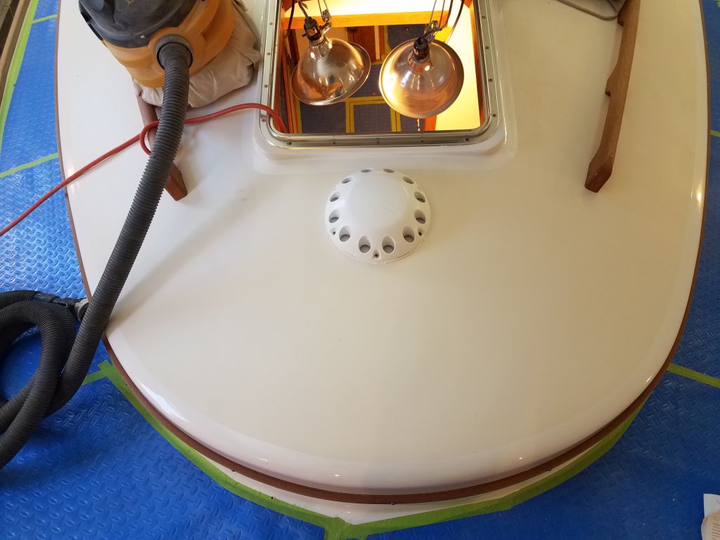
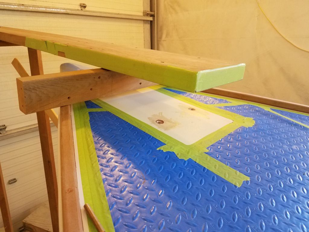
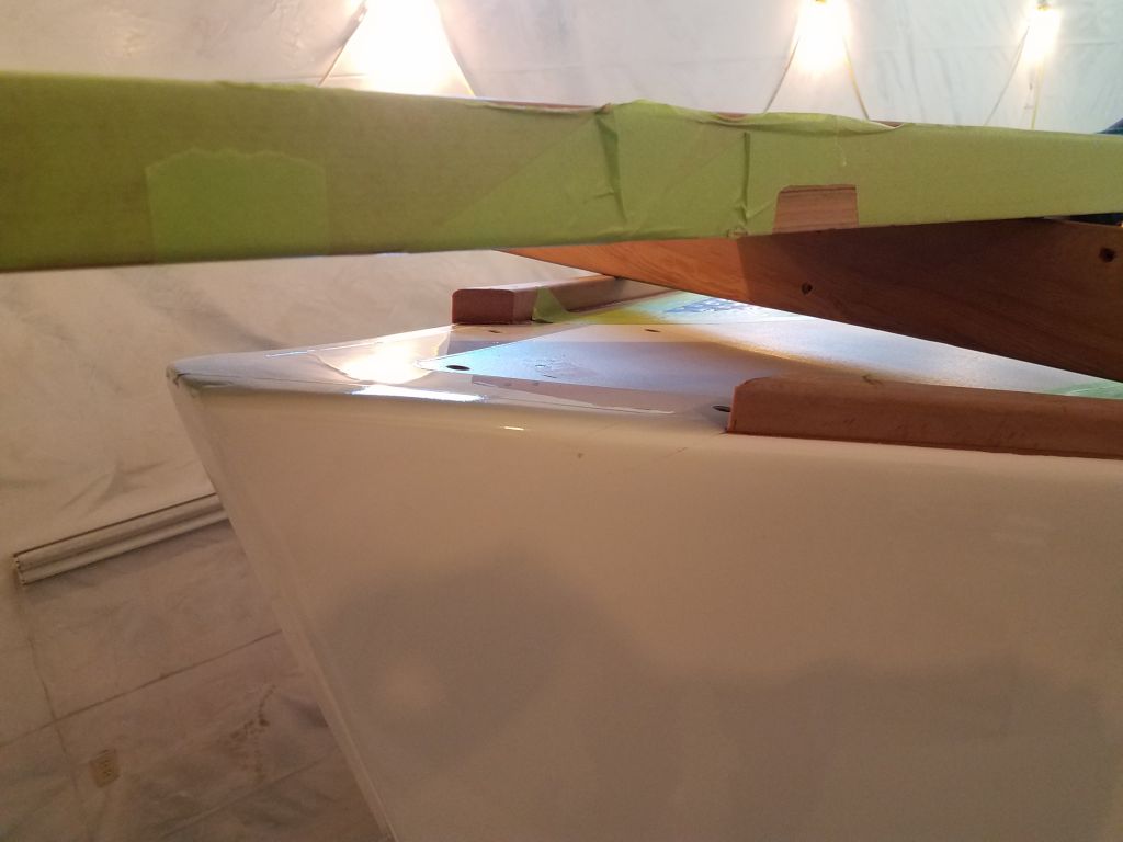
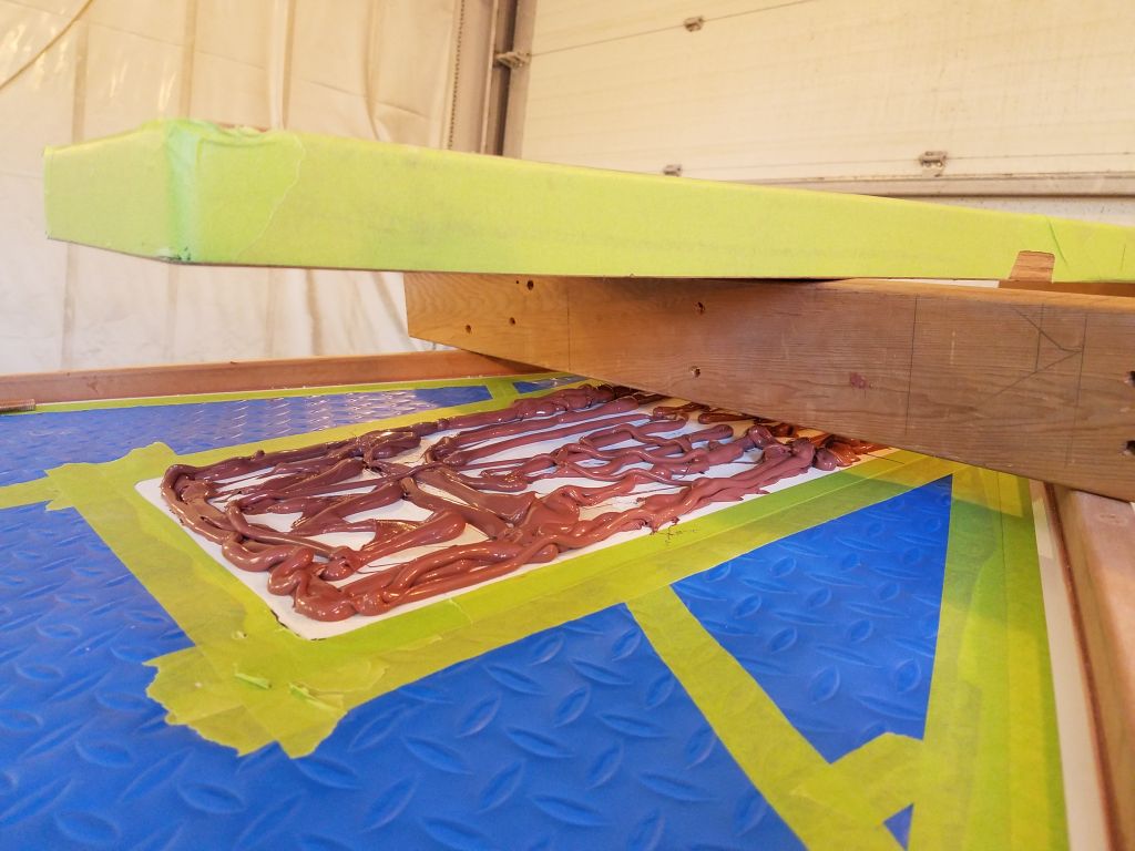
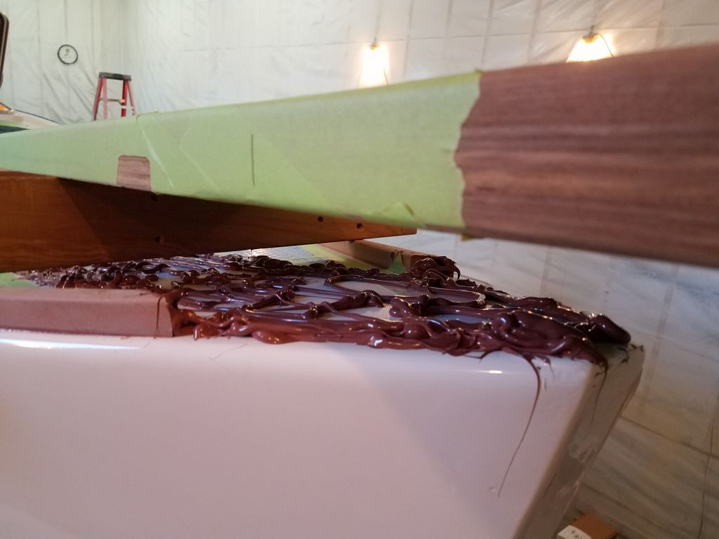
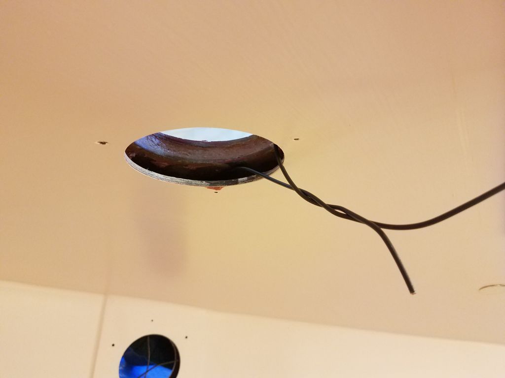
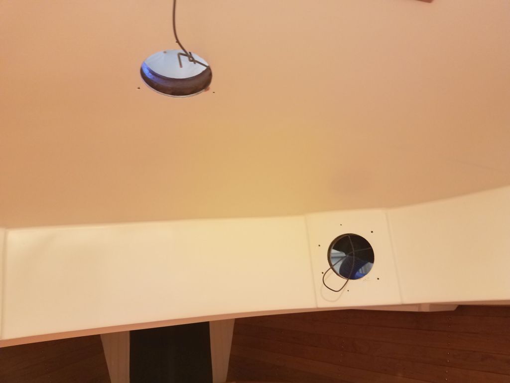
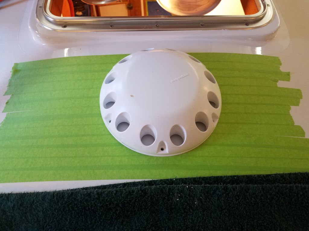
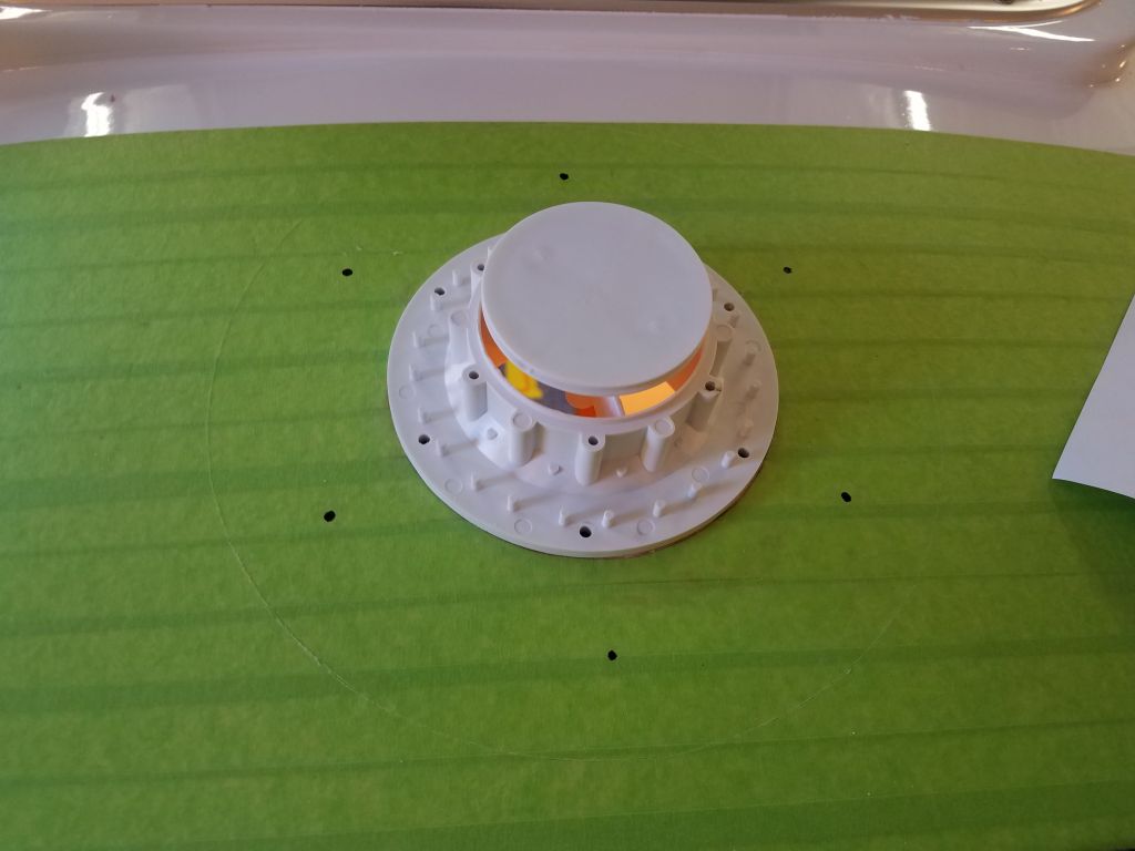
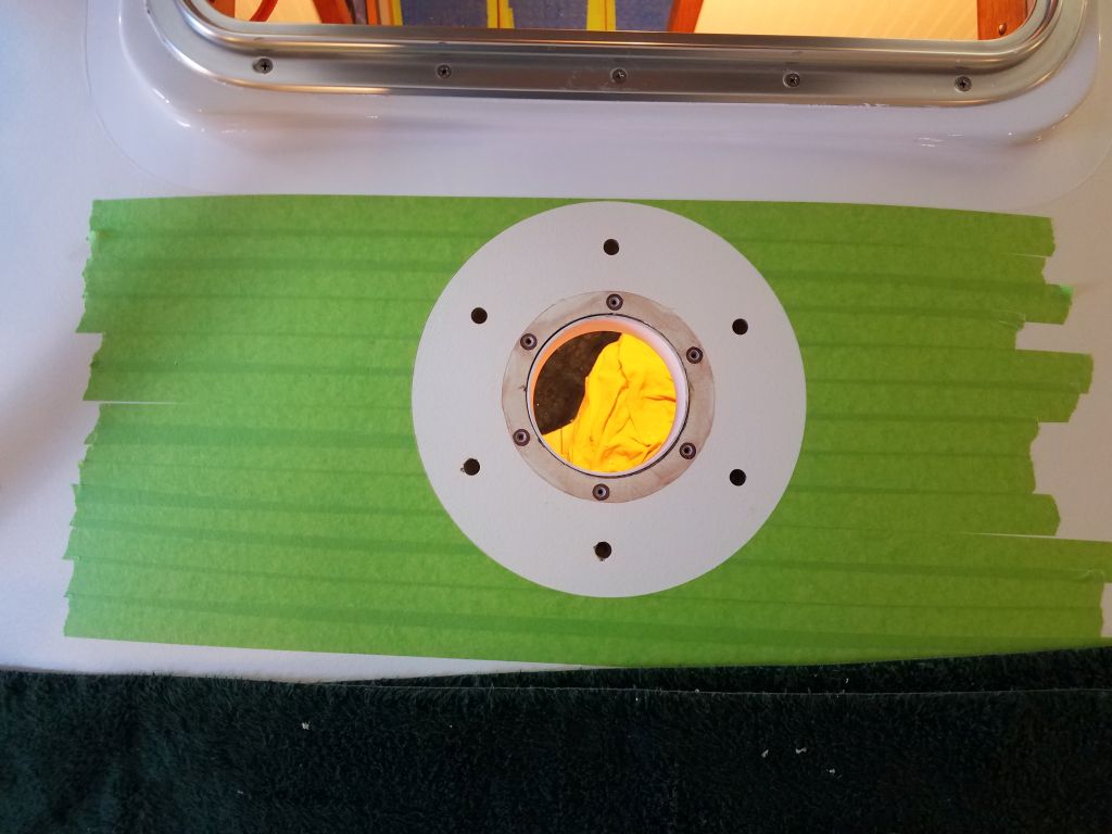
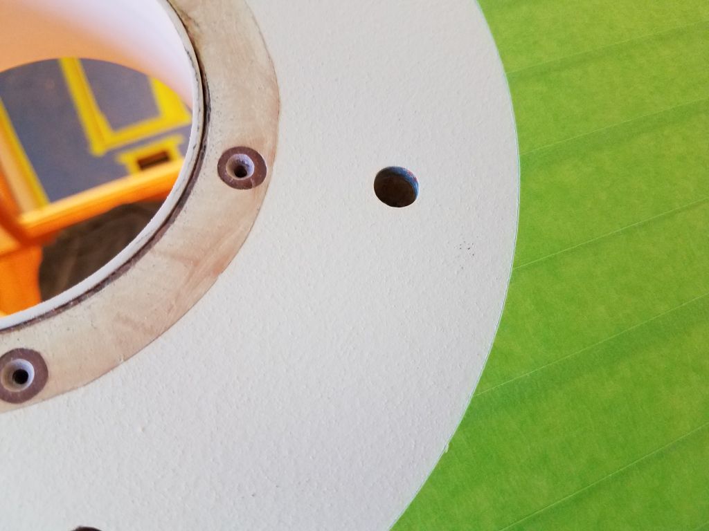
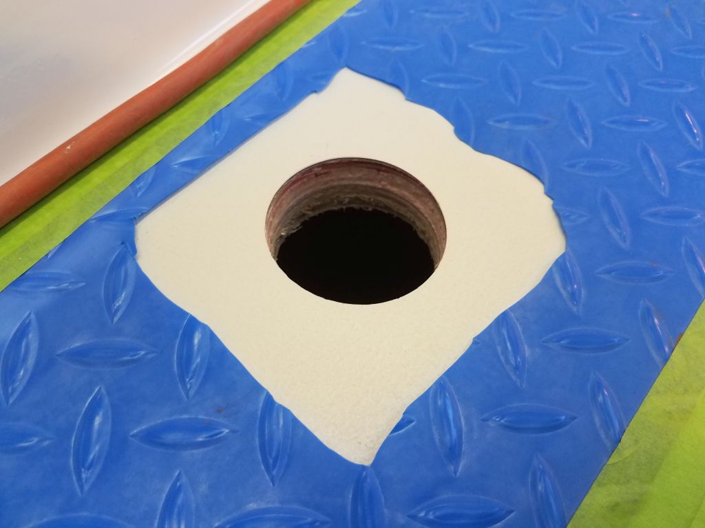
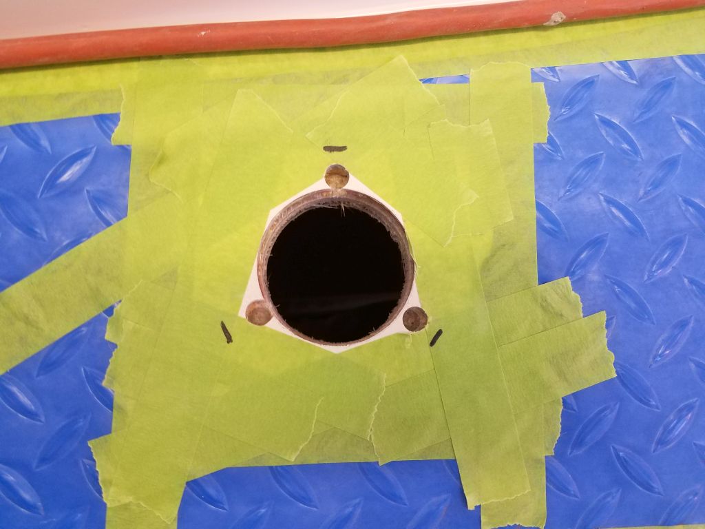
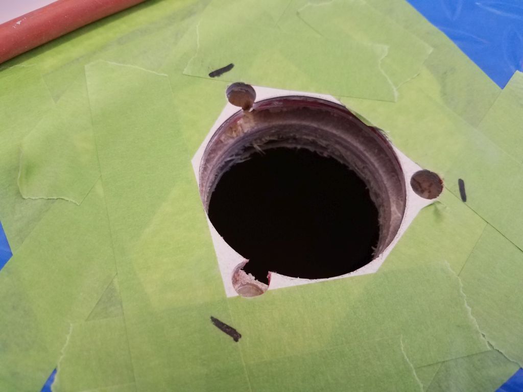
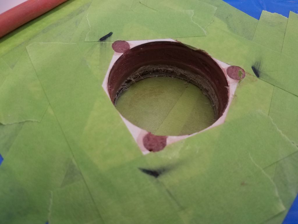
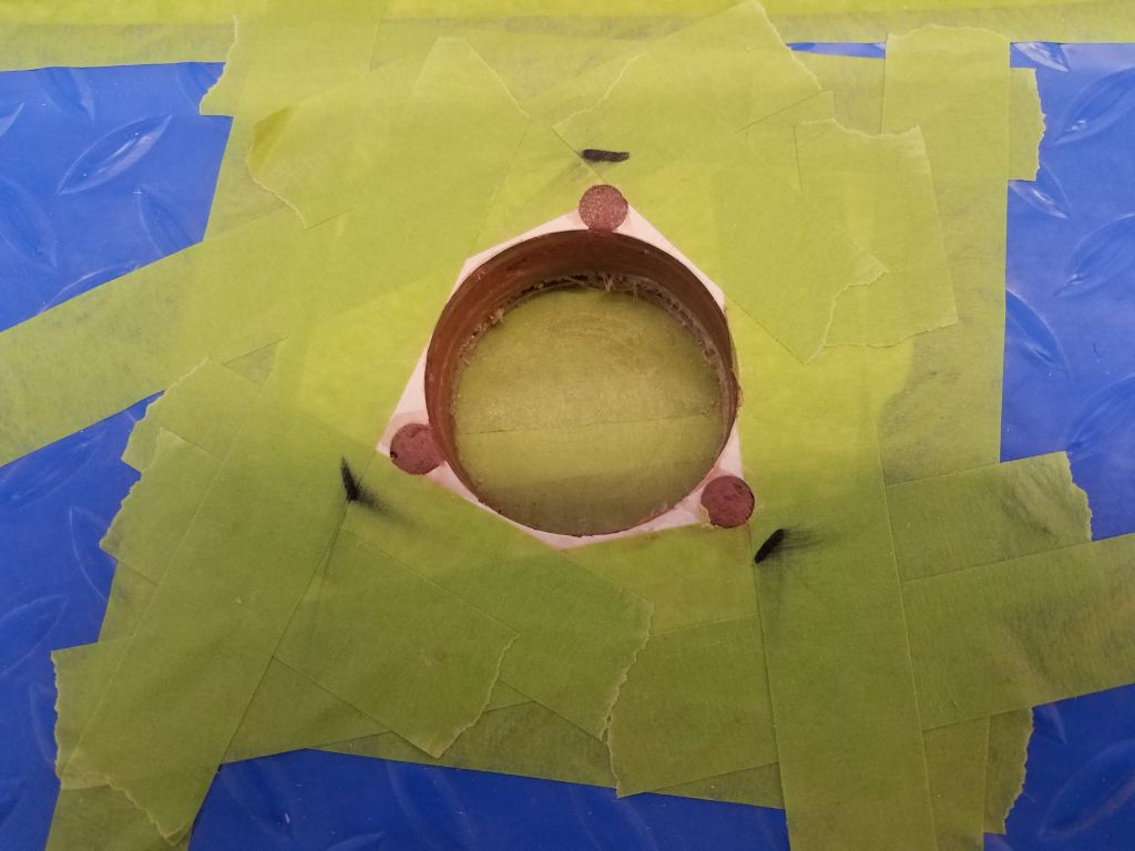
Up on deck, I prepared the area around the new deck fill location, and drilled a 2-5/16″ hole to accept the fitting. This went through a cored area of the deck (one of the areas I’d repaired much earlier in the project), so as usual I removed the coring from around the hole’s edges, and drilled 3/8″ holes at the fastener locations to omit the core in those areas as well. Afterwards, I filled the voids with a thickened epoxy mixture.
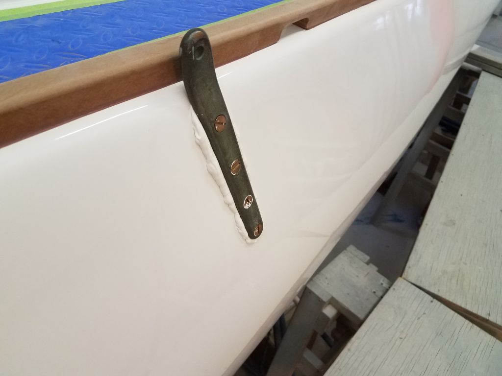
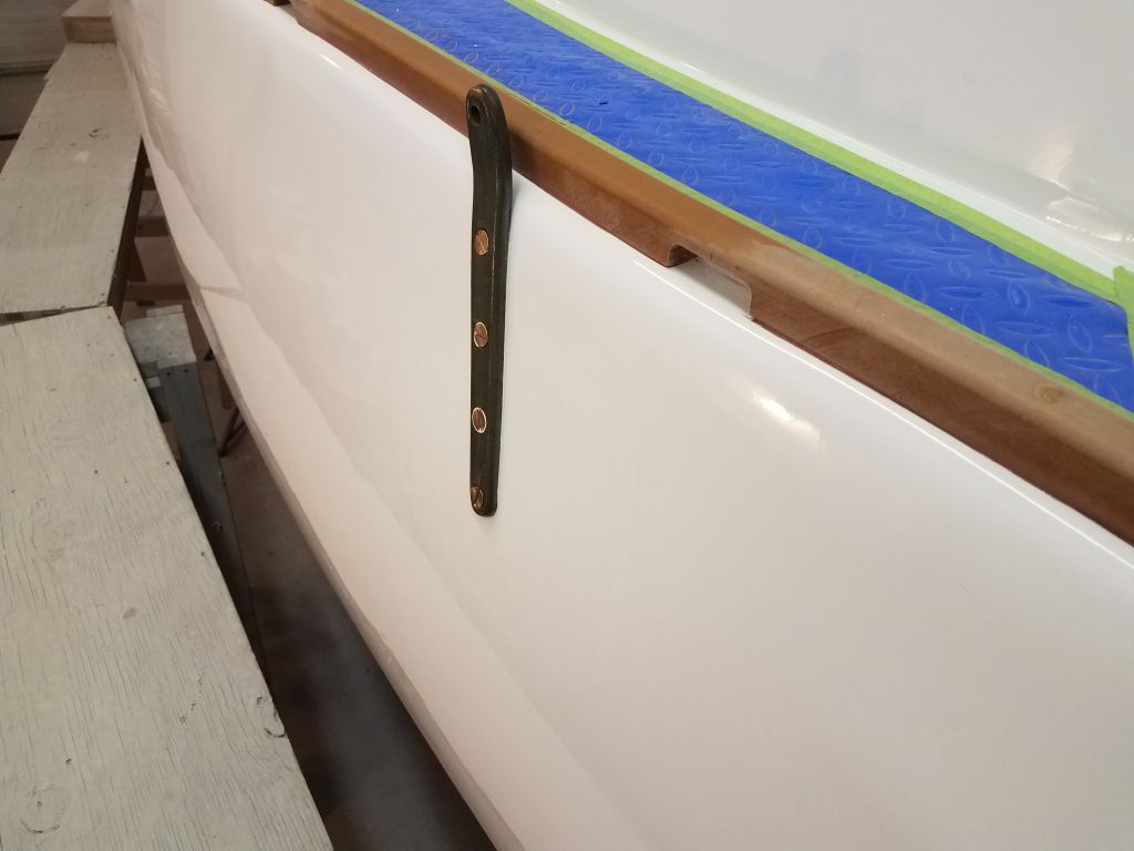
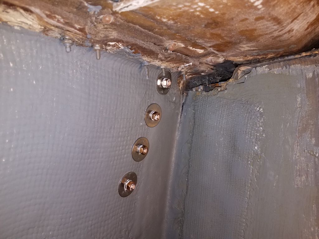
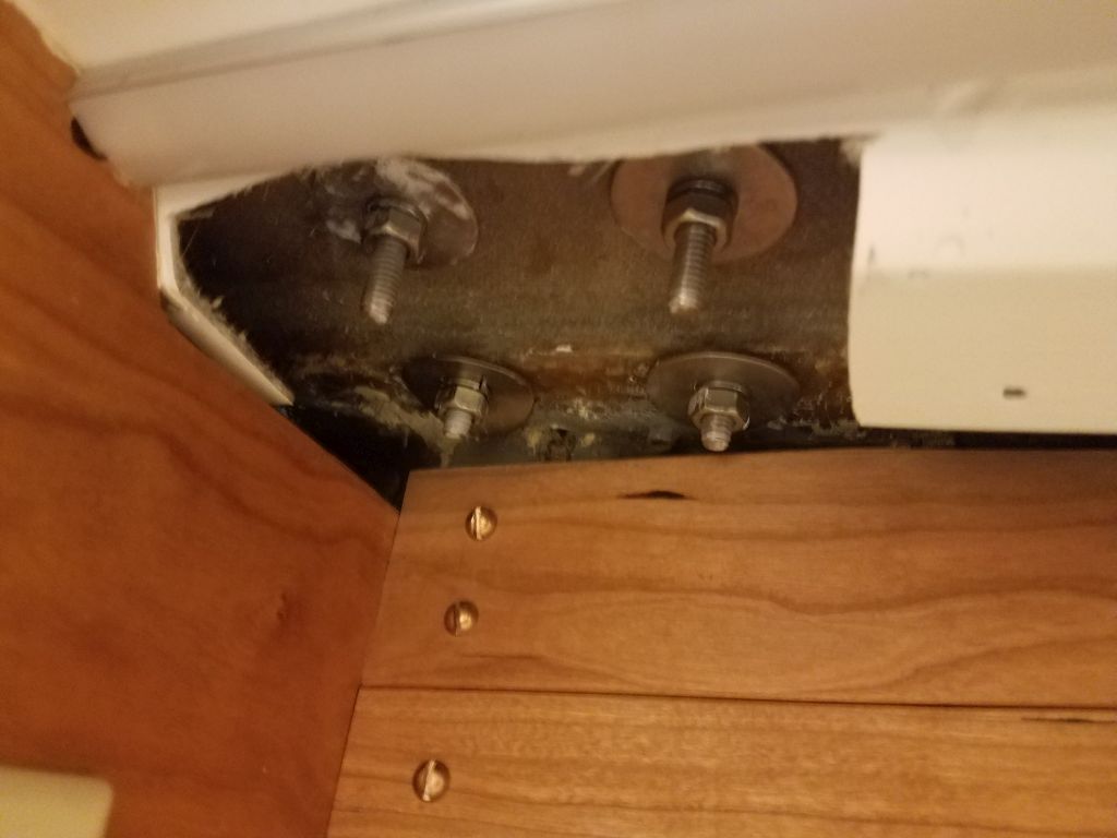
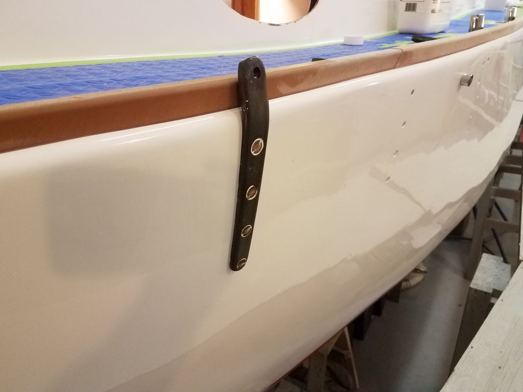
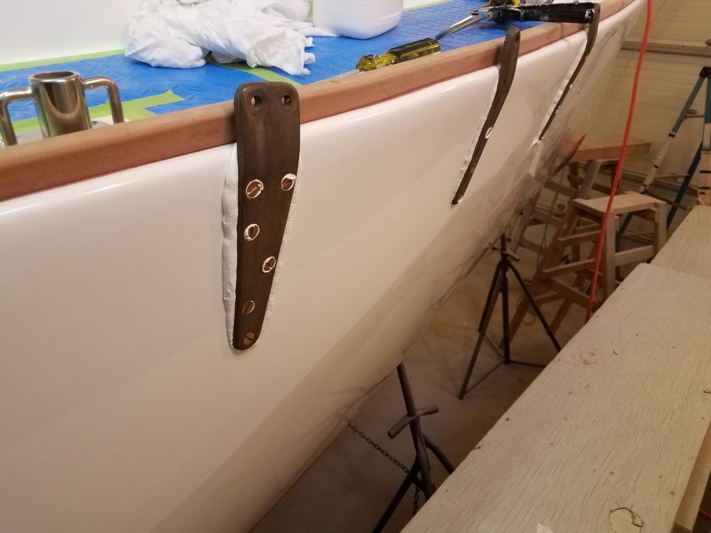
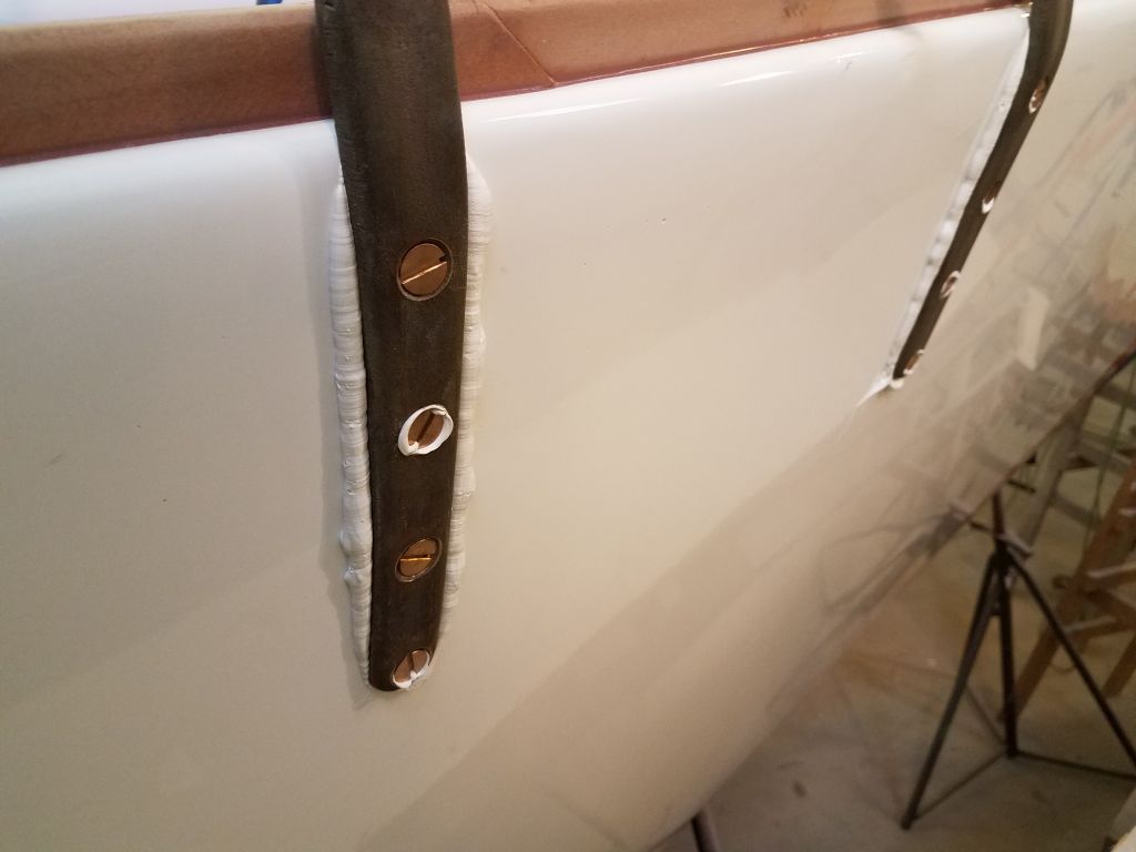
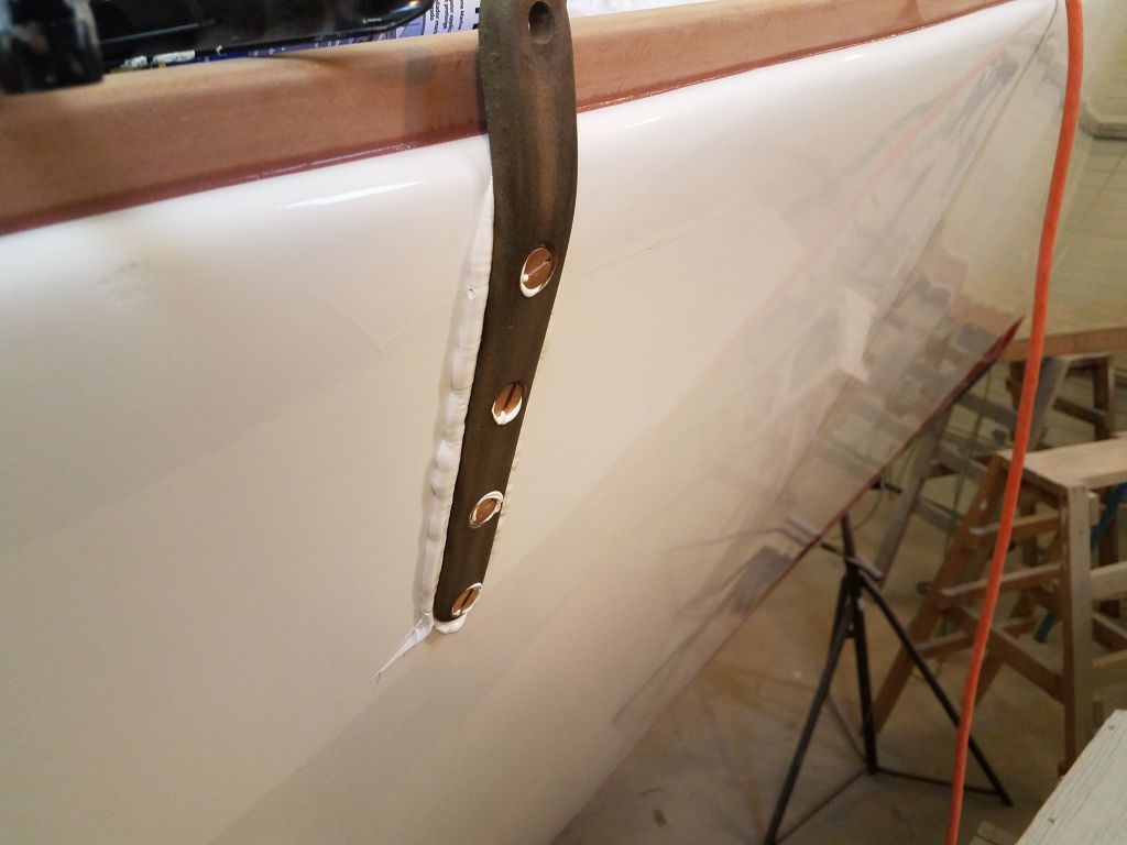
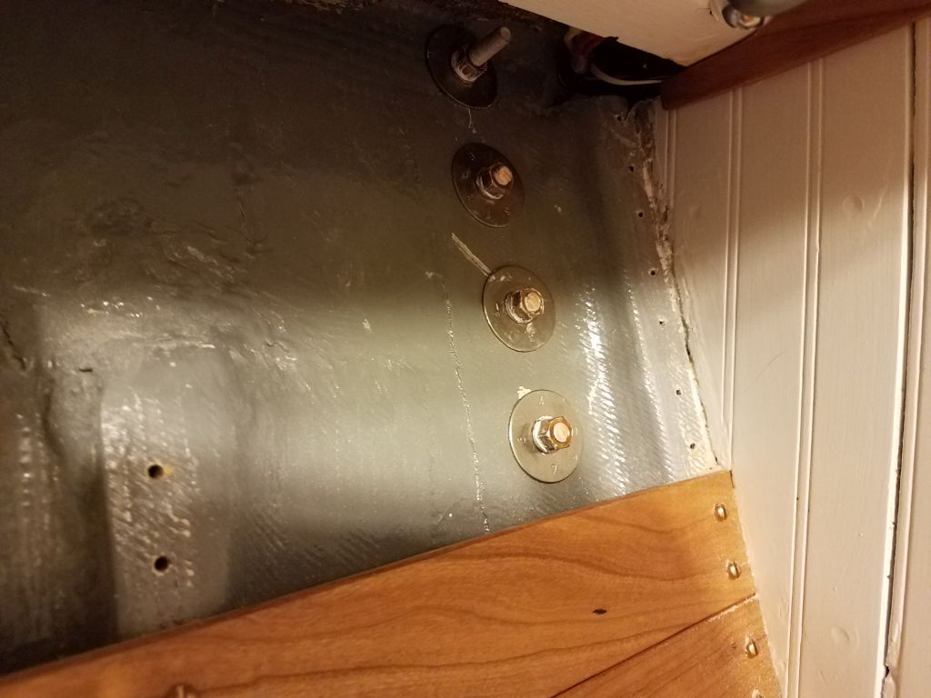
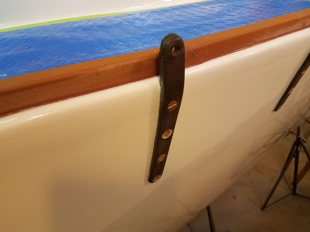
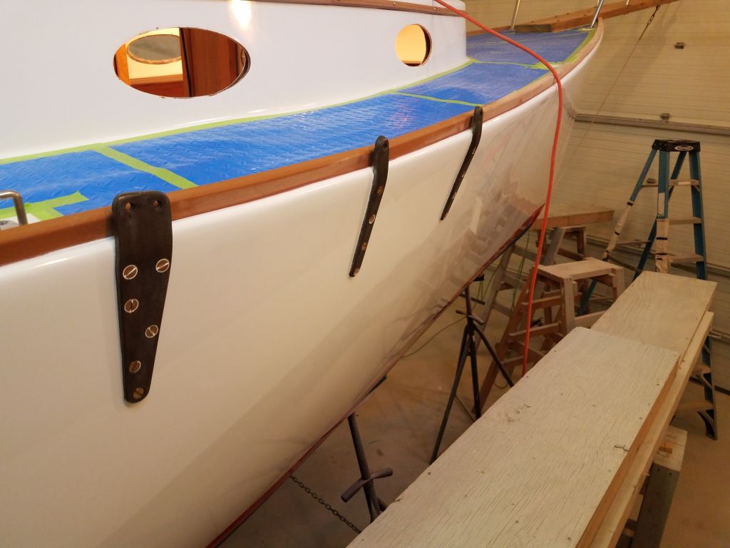
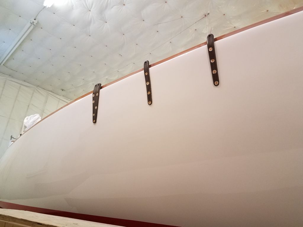
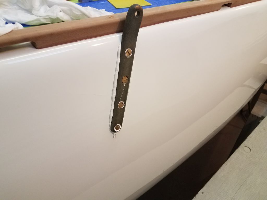
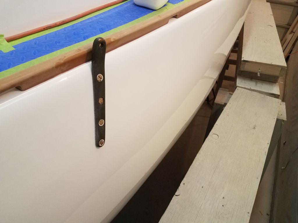
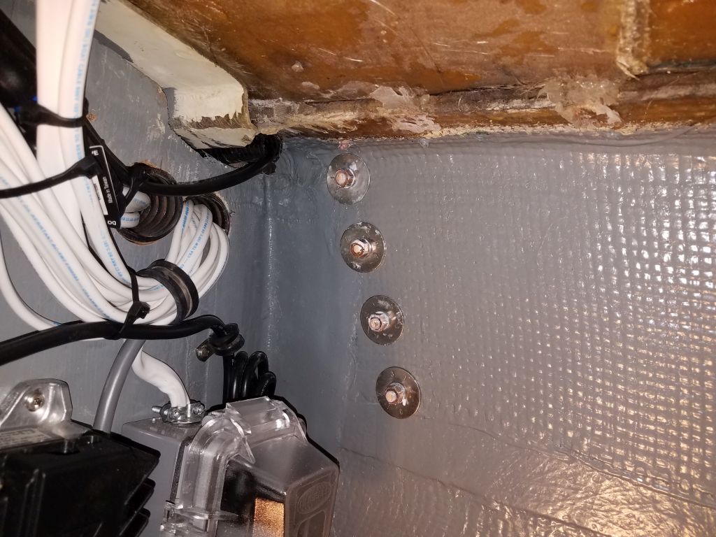
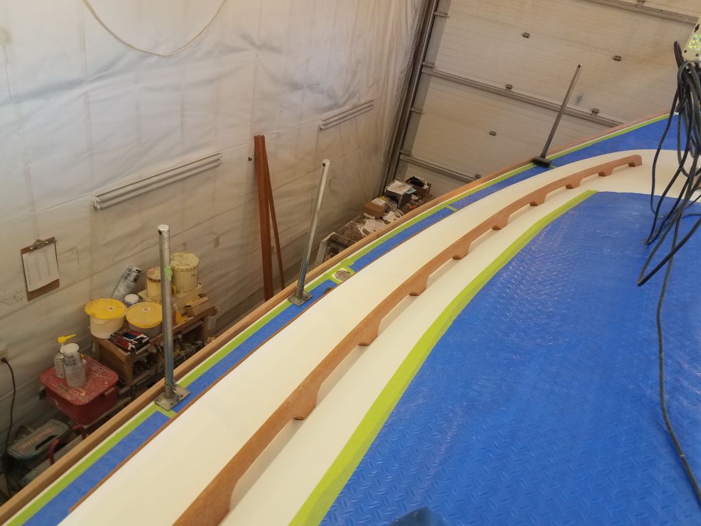
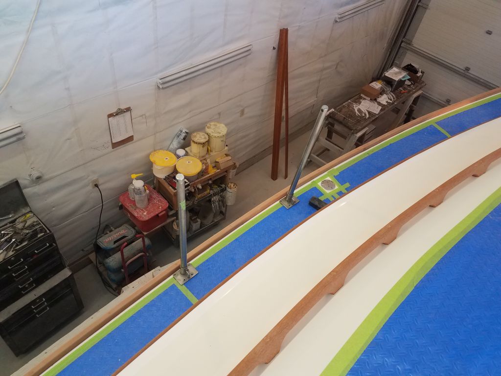
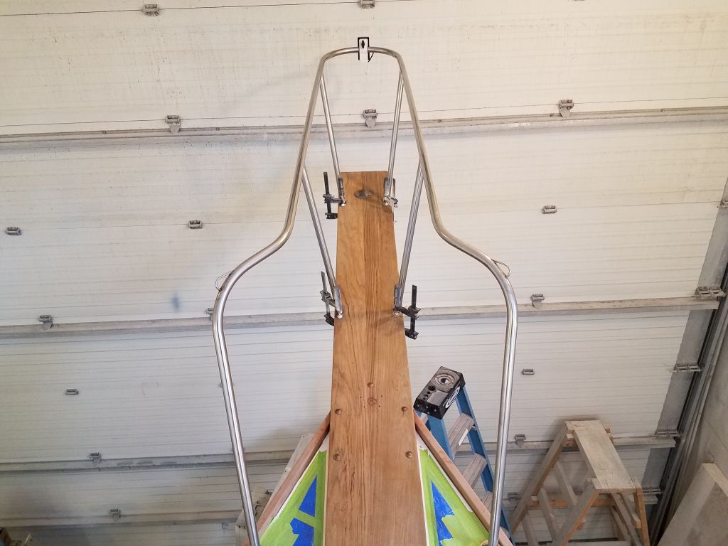
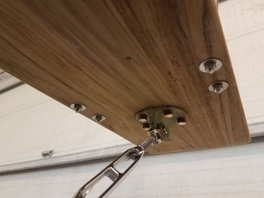
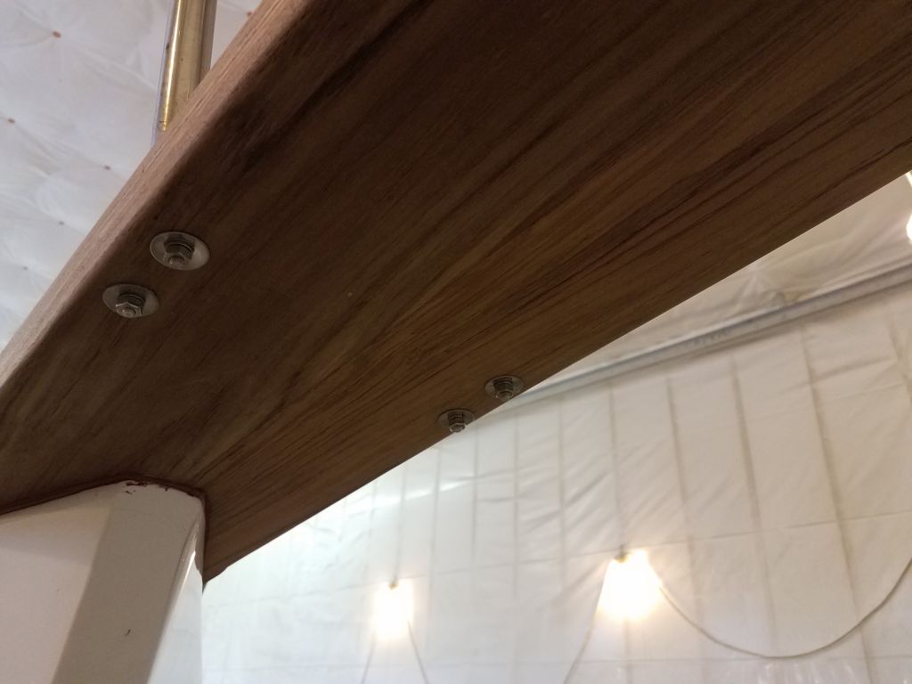
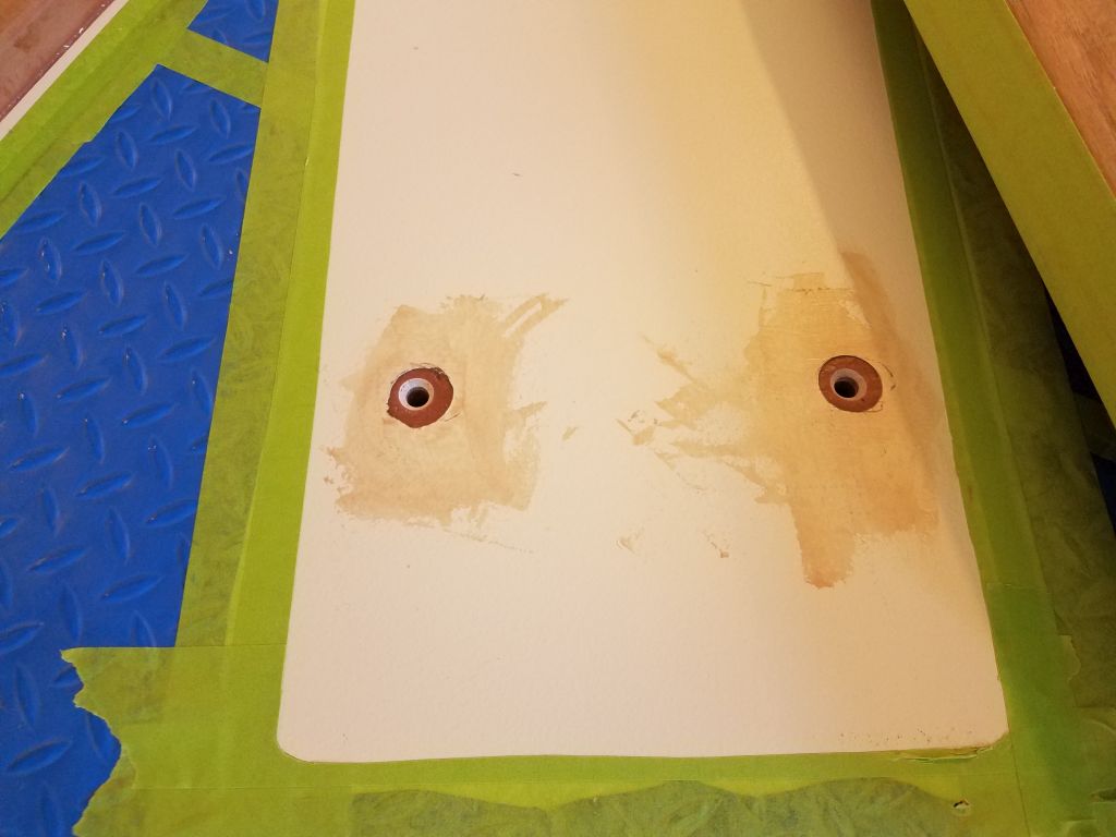
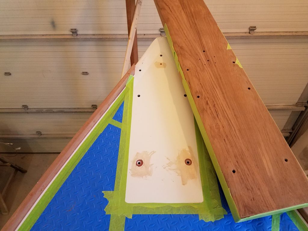
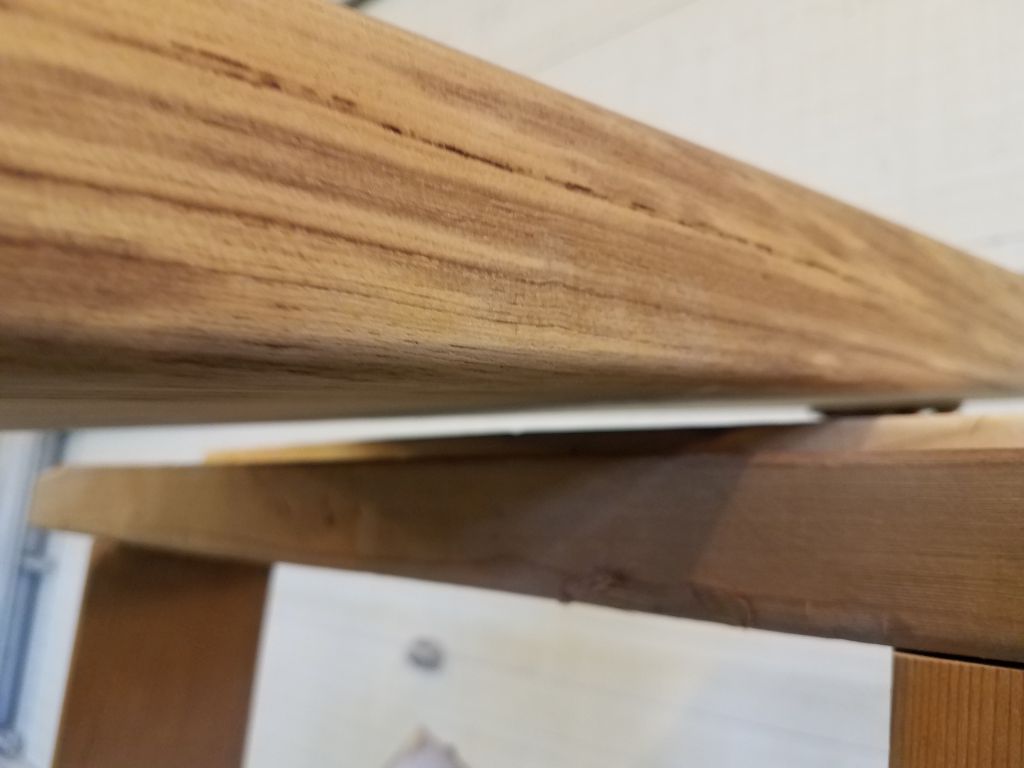
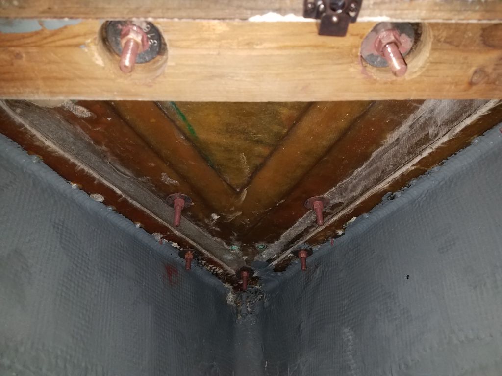
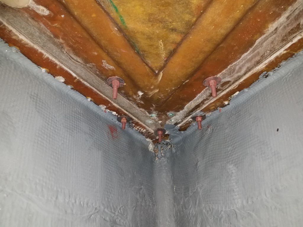
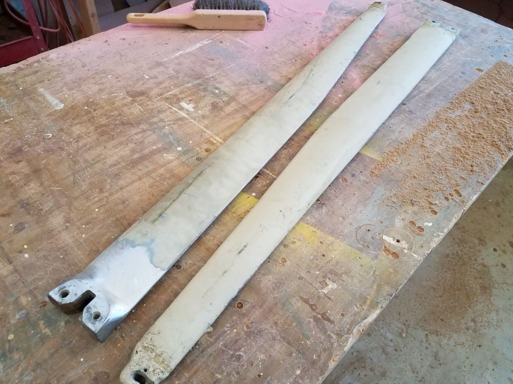
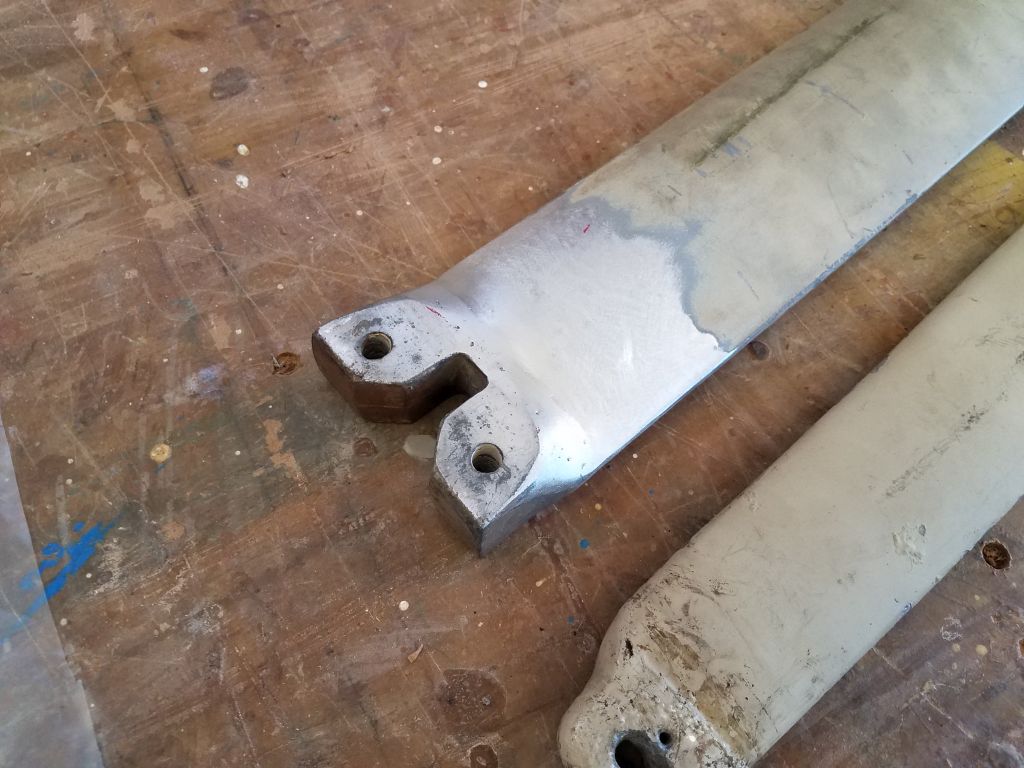
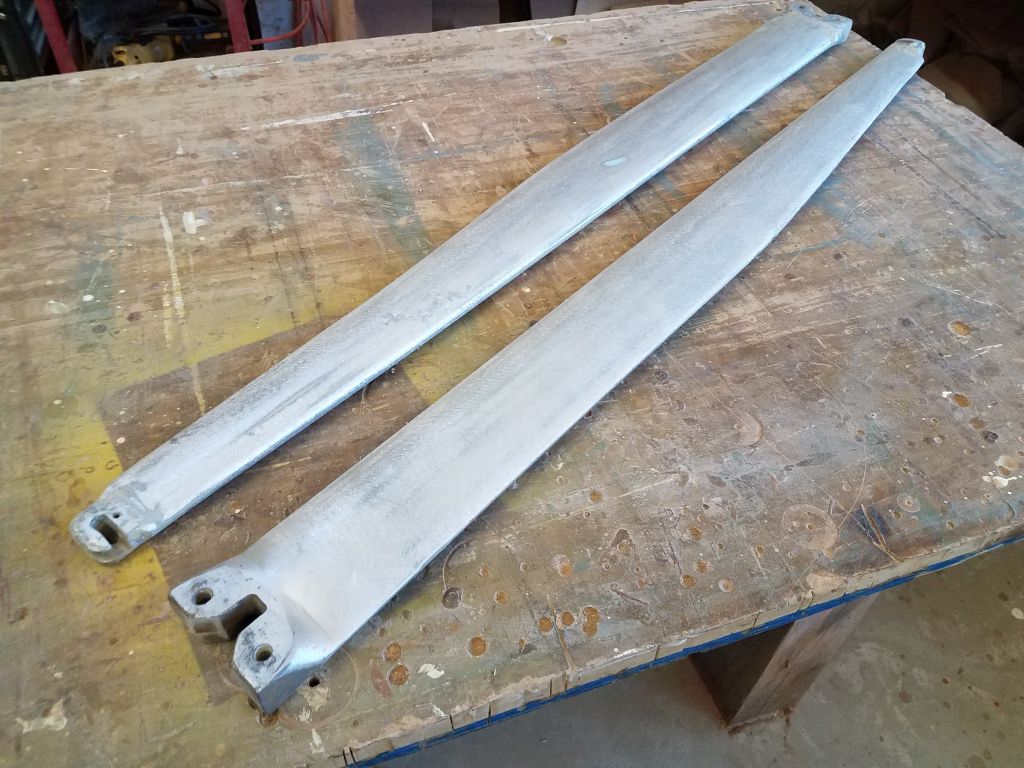
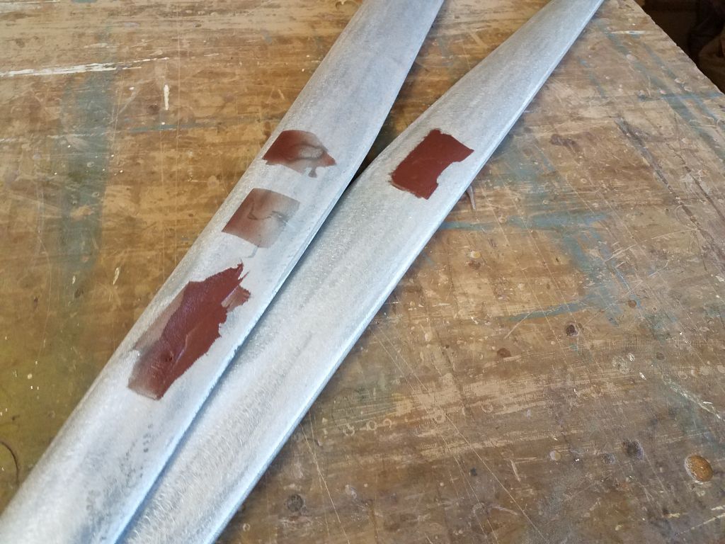
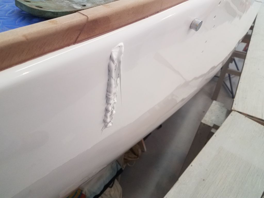
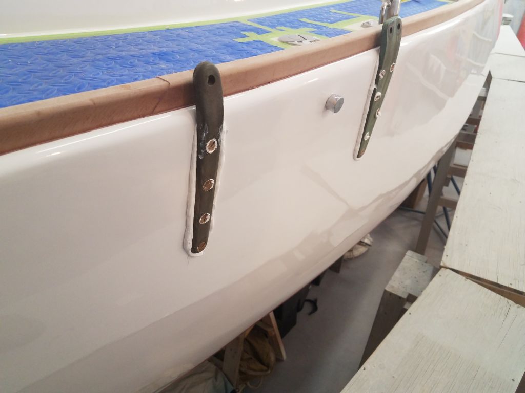
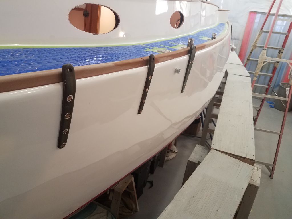
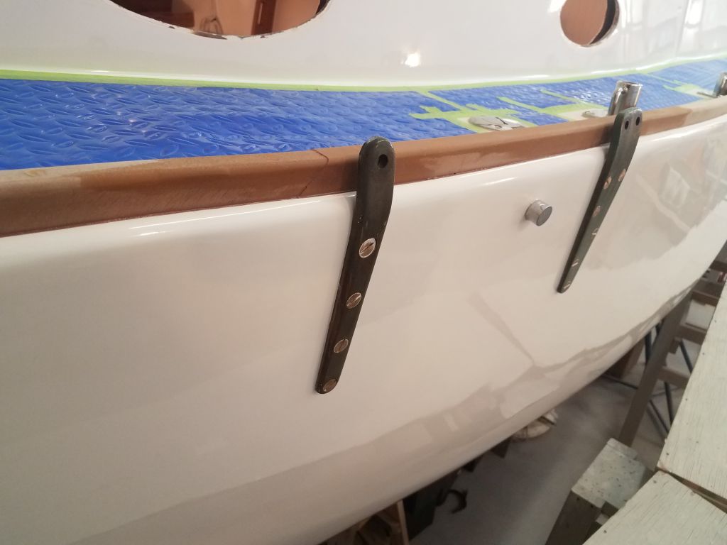
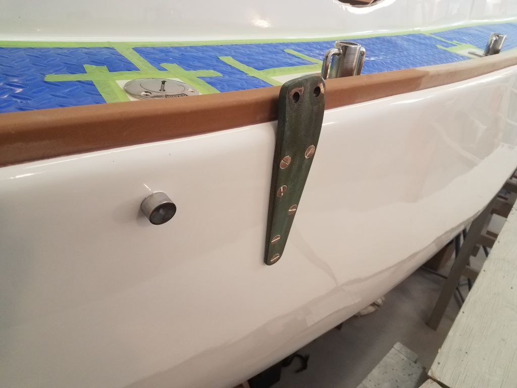
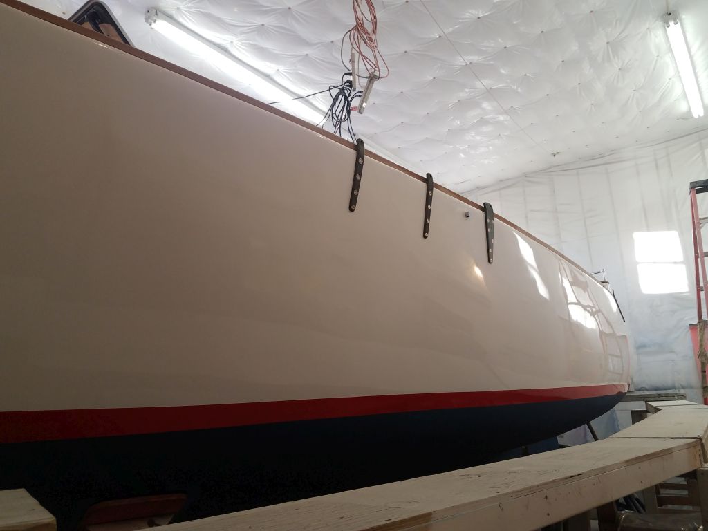
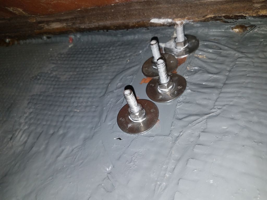
On the port side, I installed the final two chainplates with the longer bolts I’d ordered for the purpose.
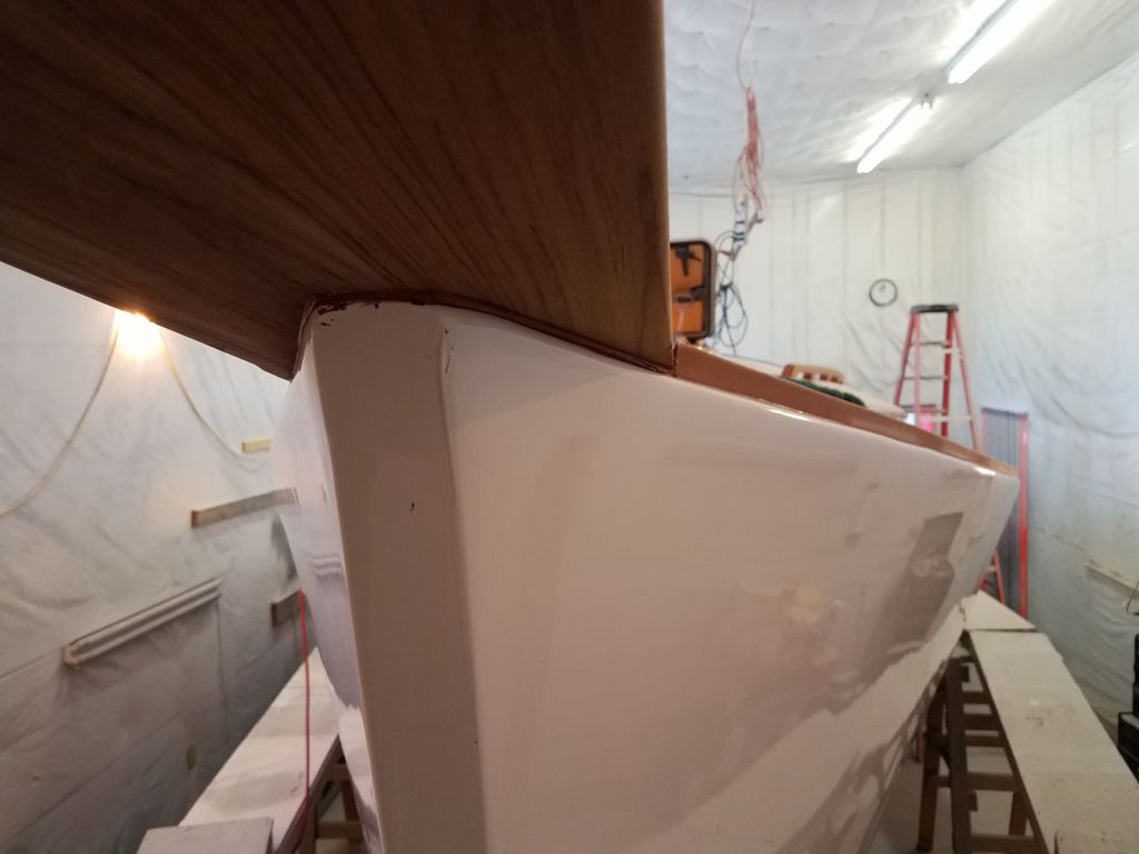
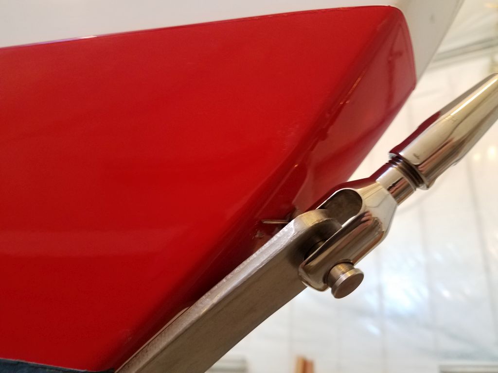
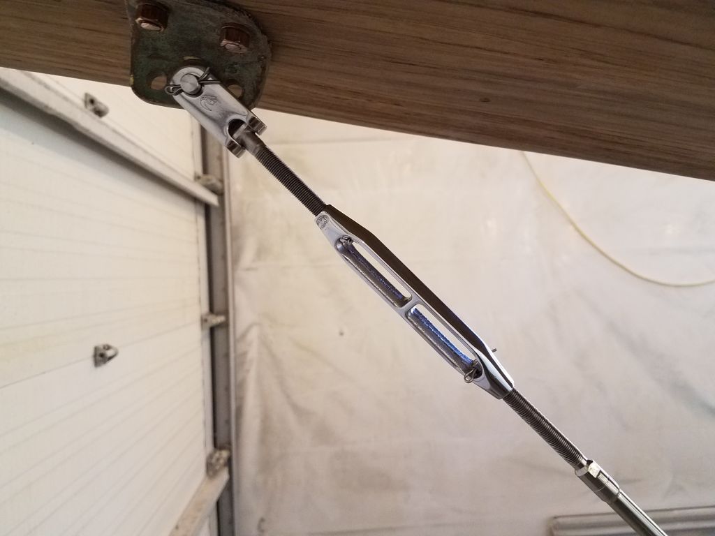
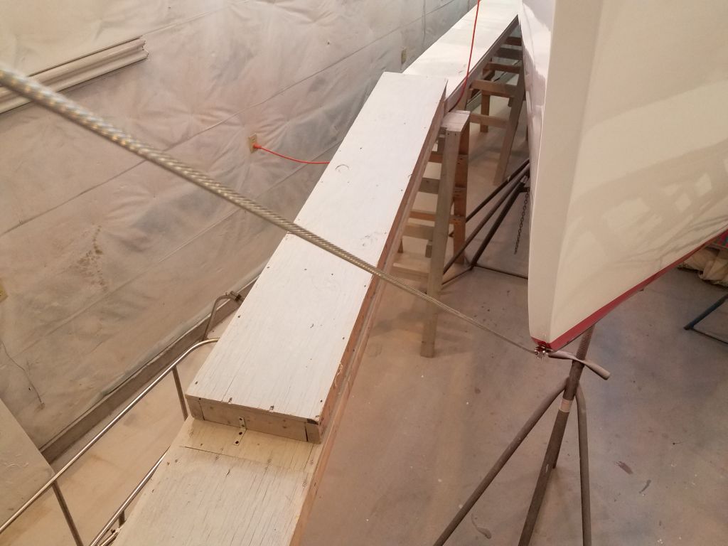
I finished up the chainplates with the backstay chainplate at the transom.

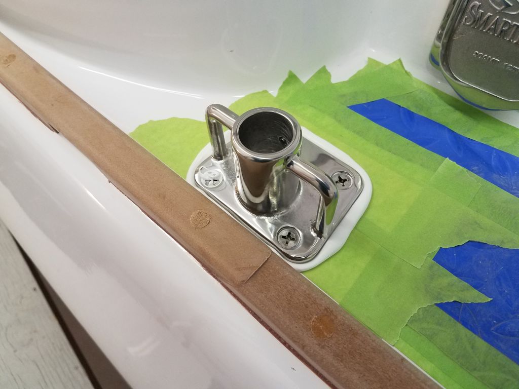
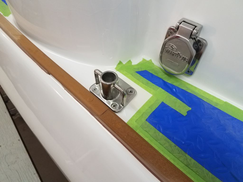
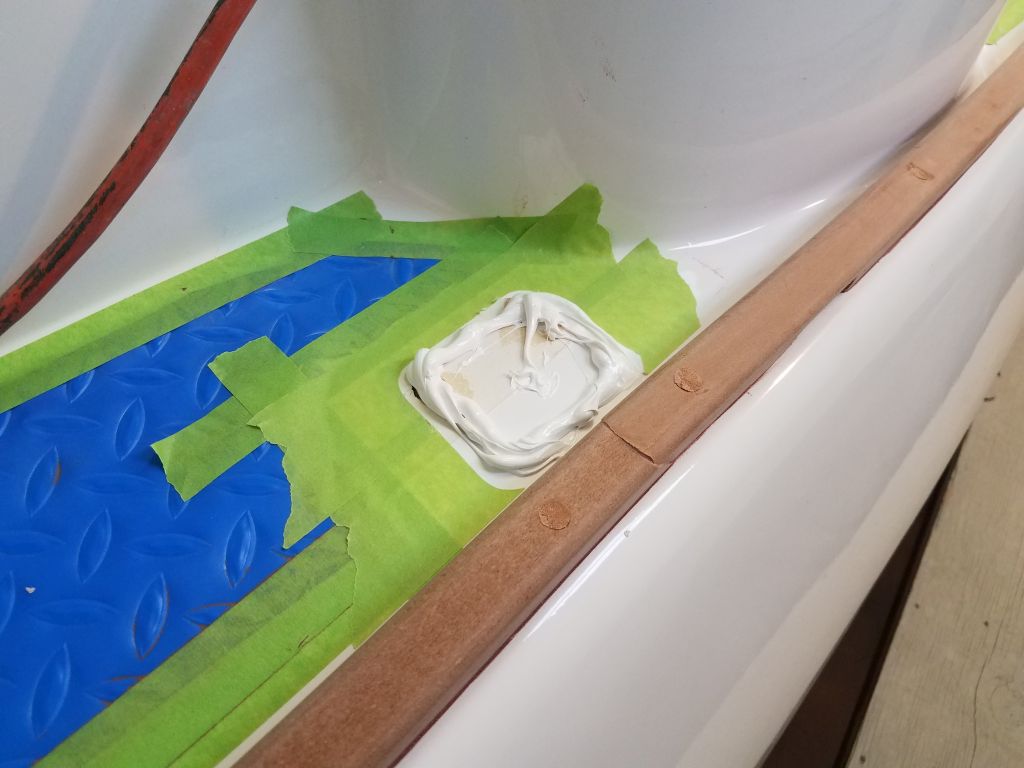
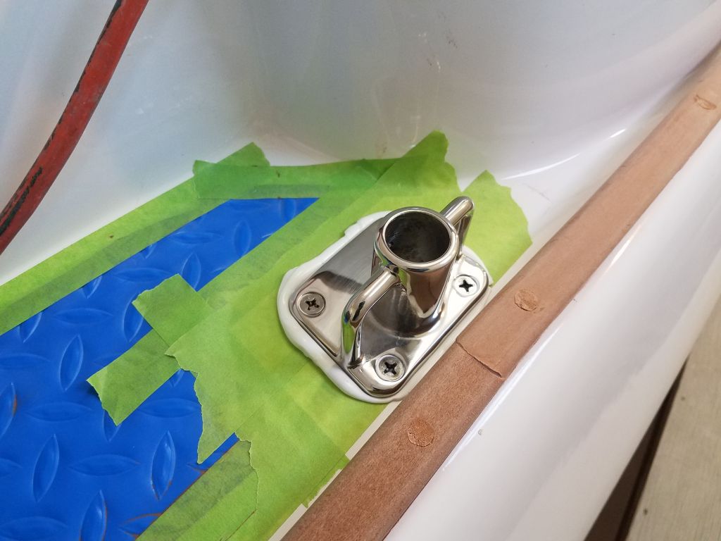
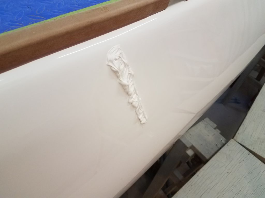
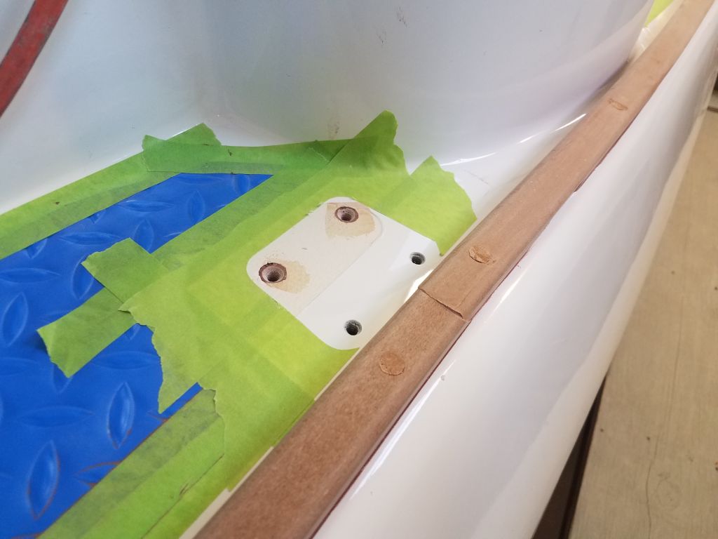
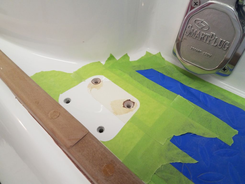
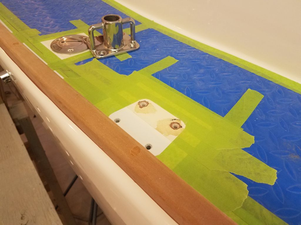
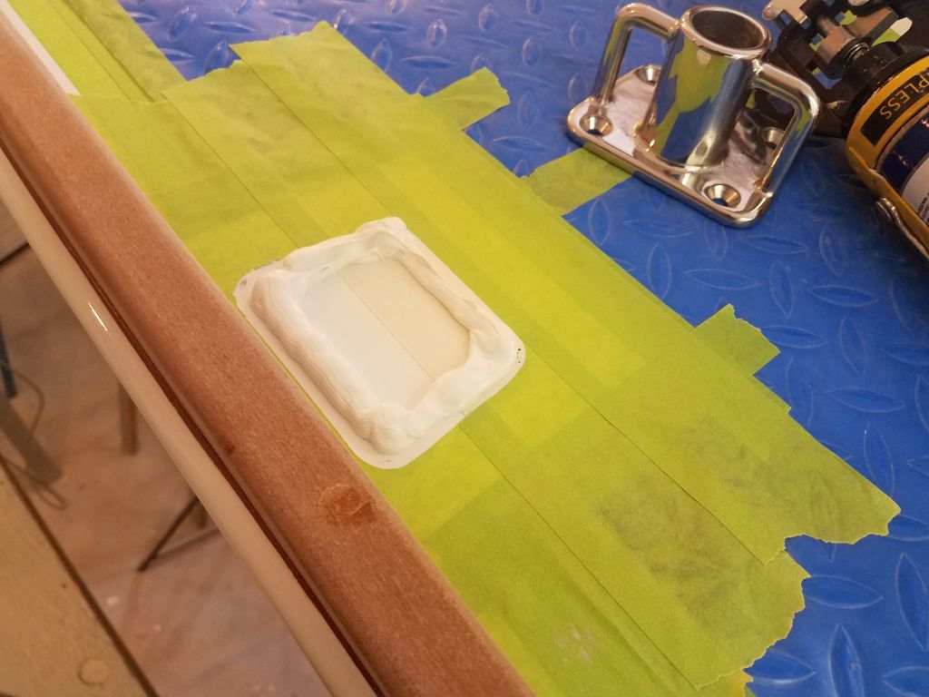
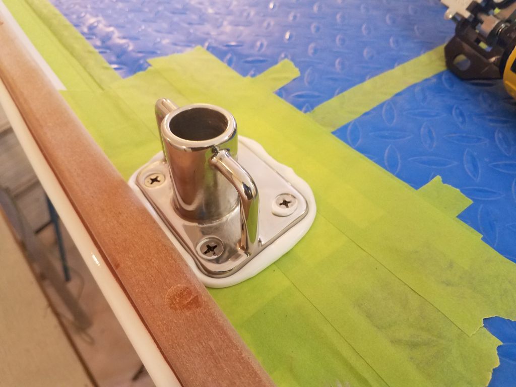
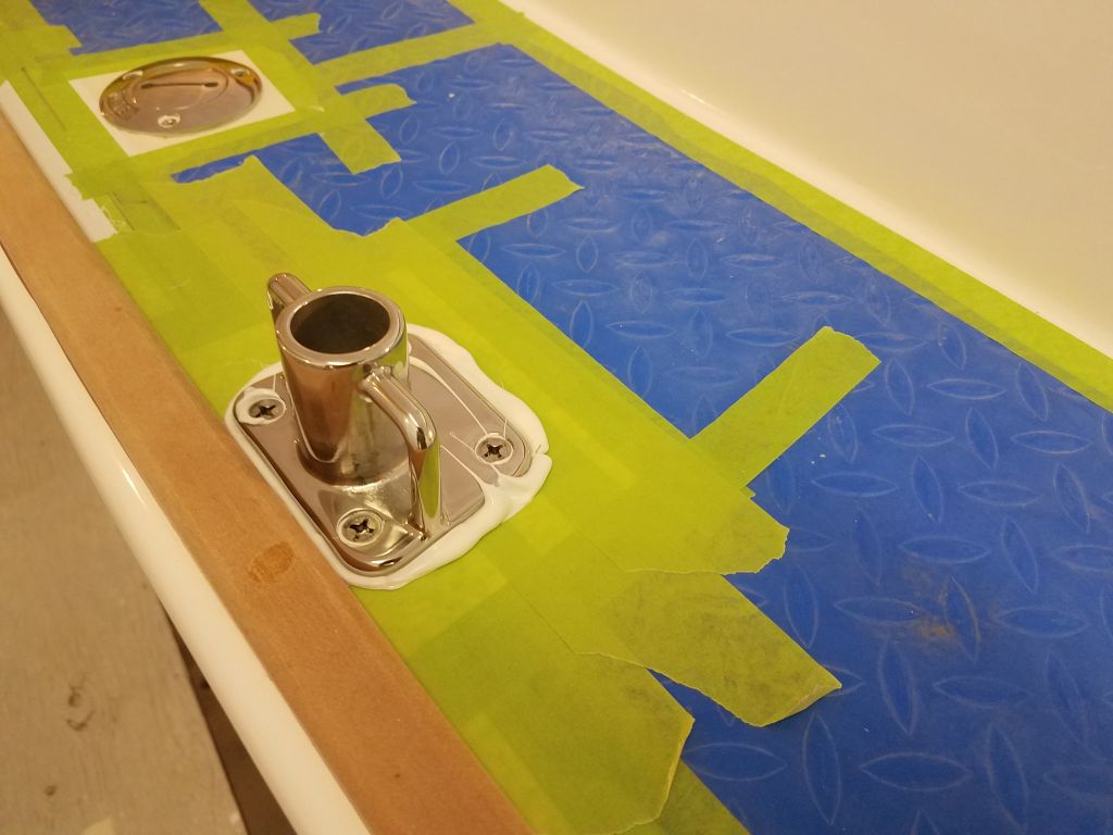
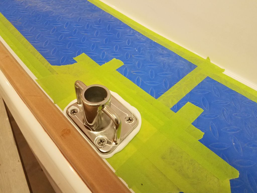
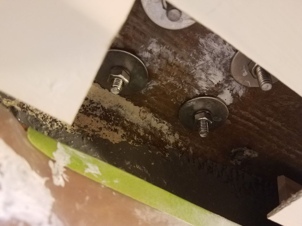
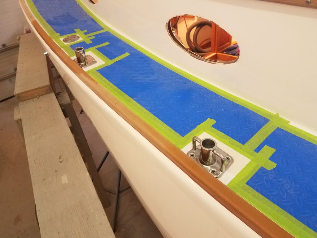
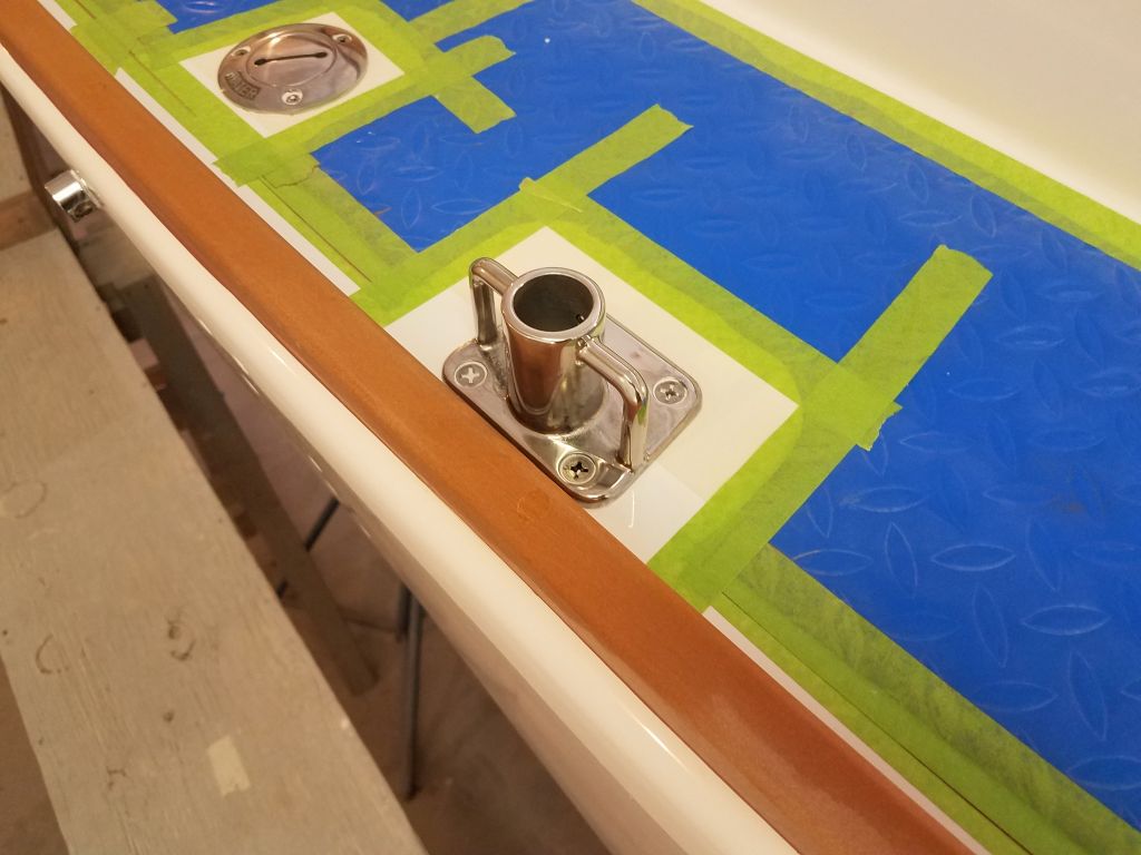
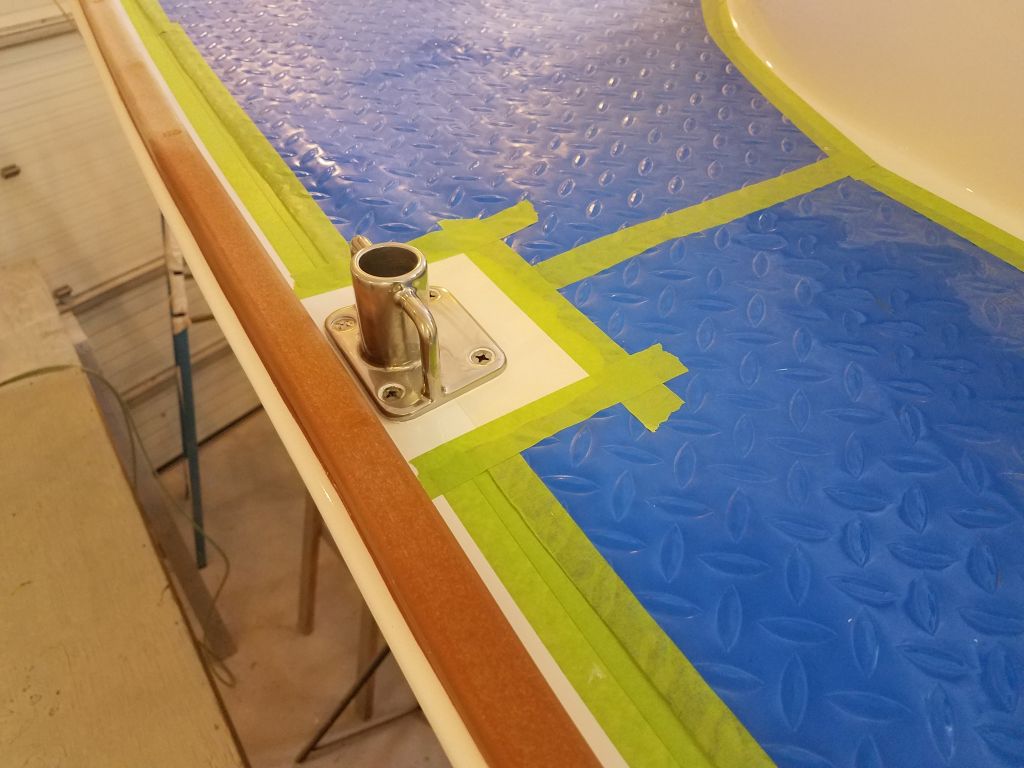
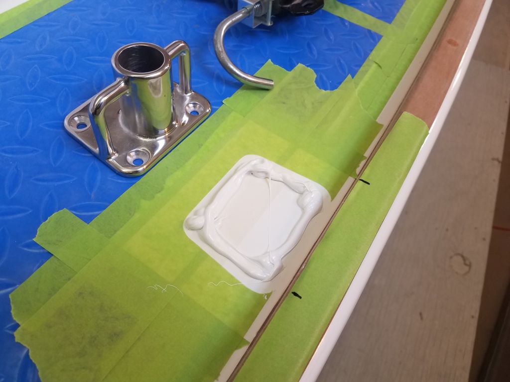
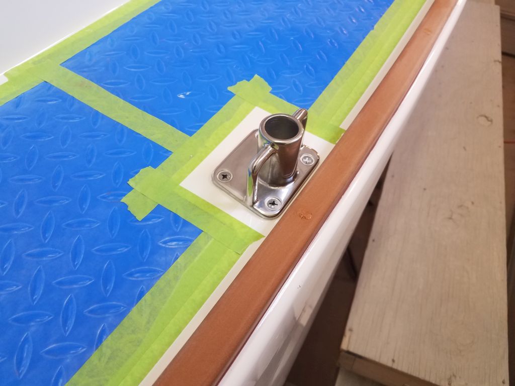
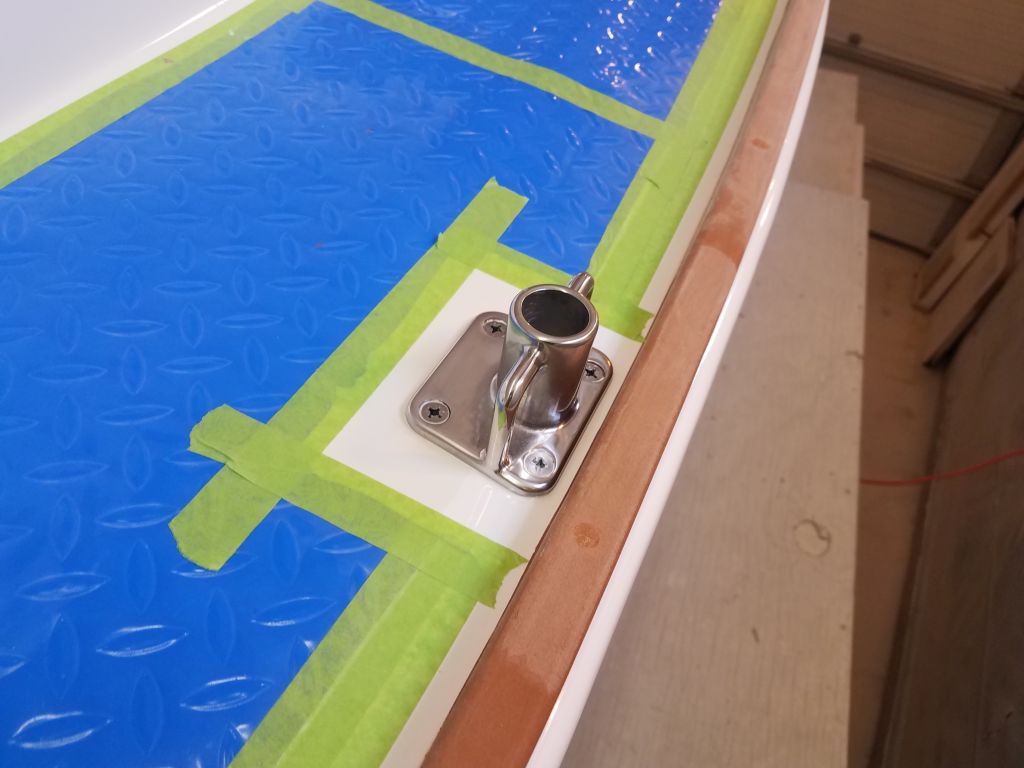
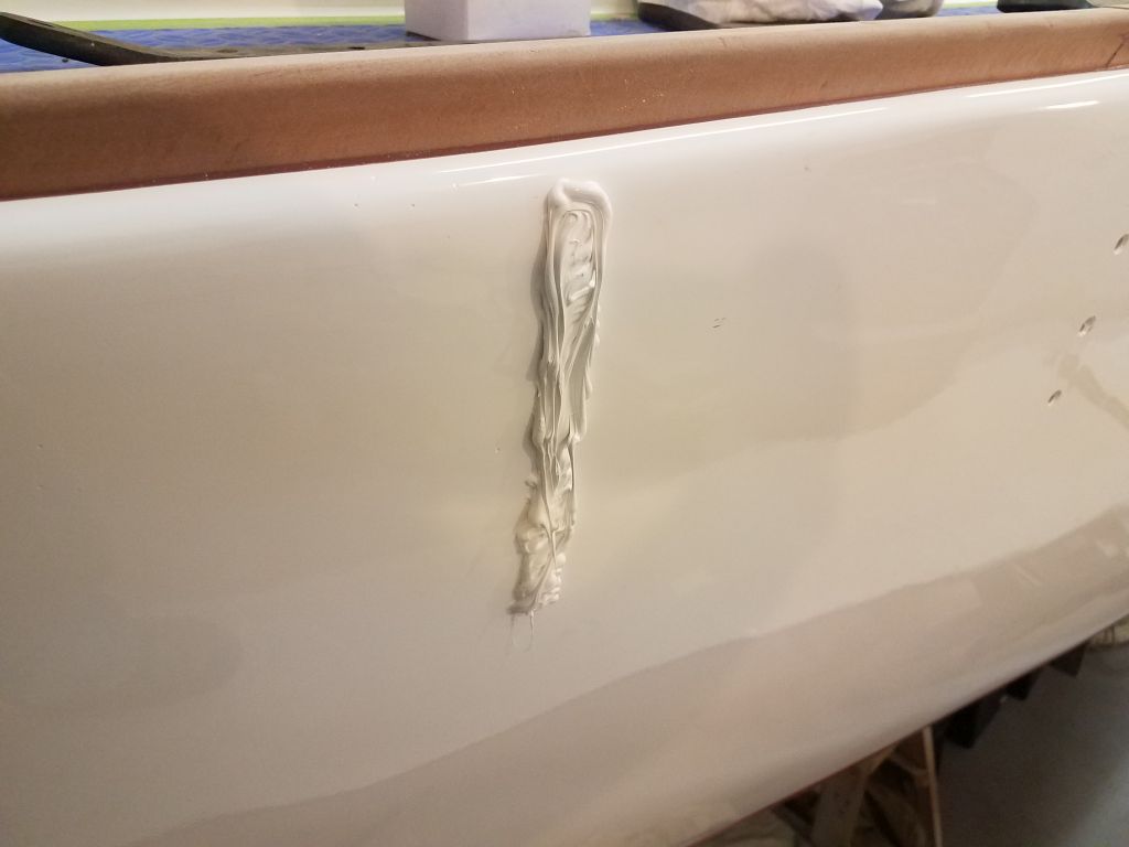
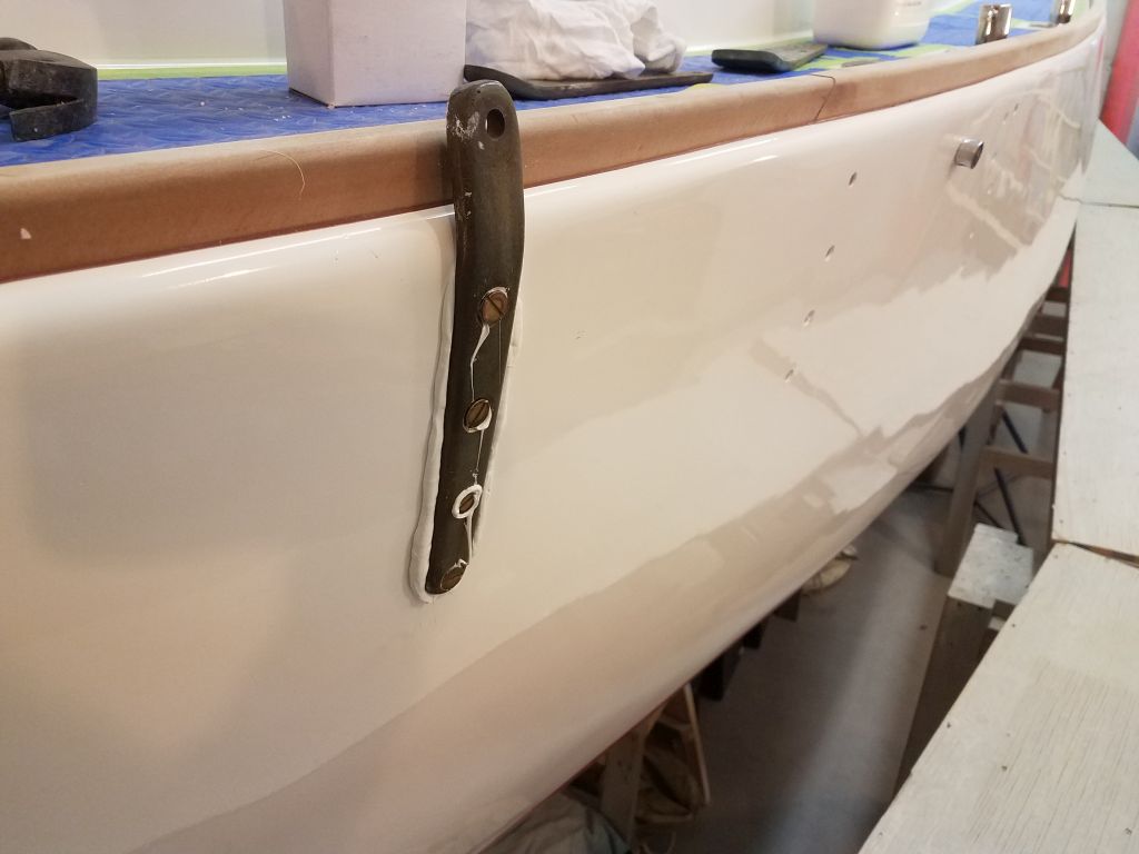
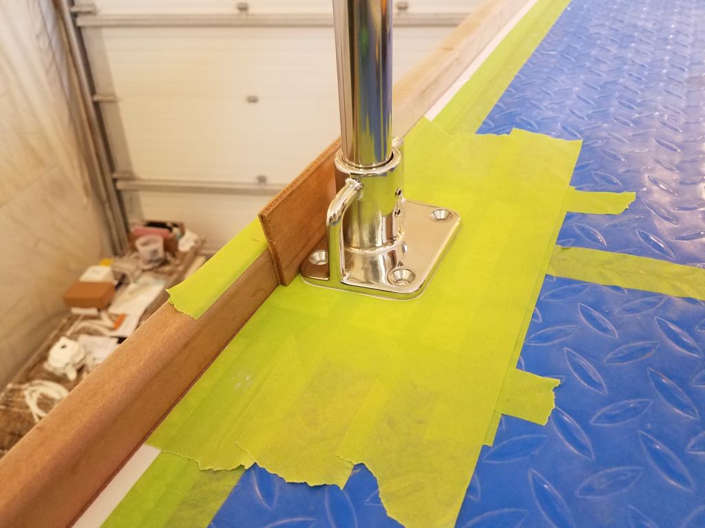
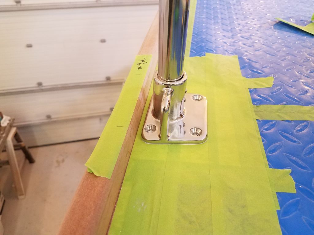
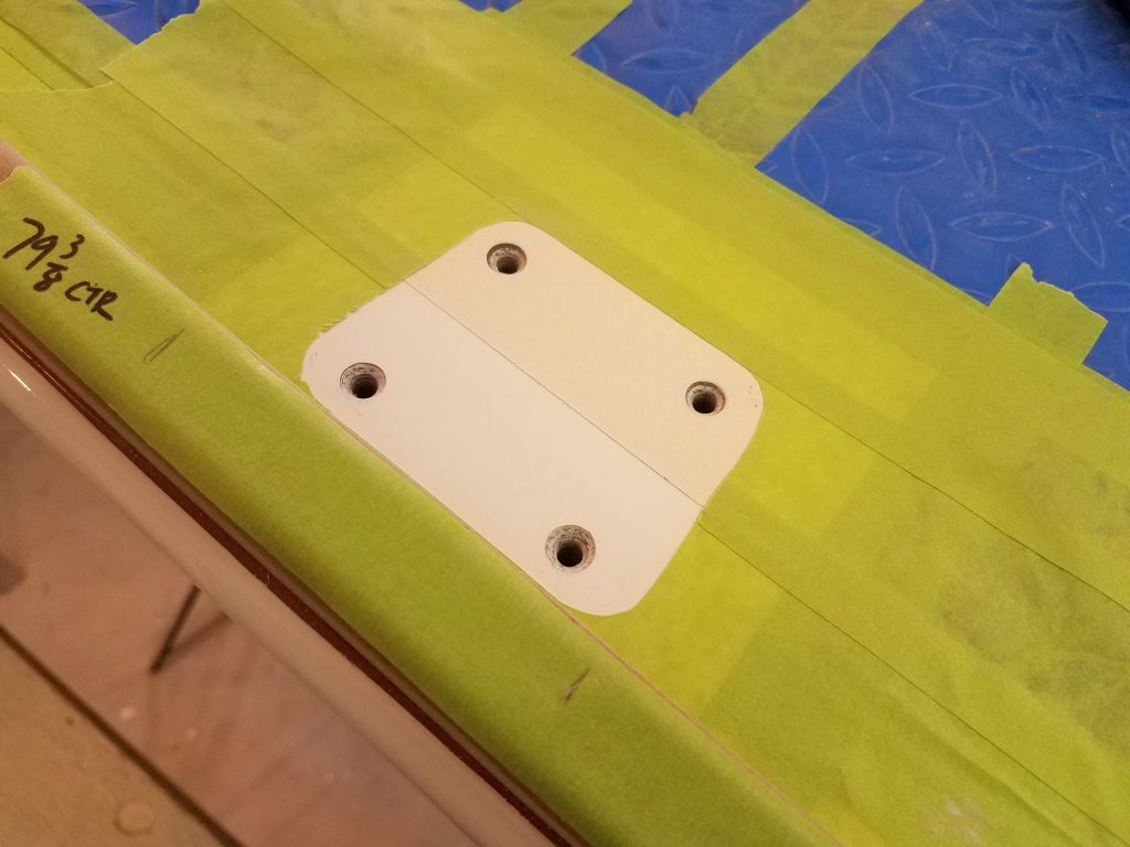
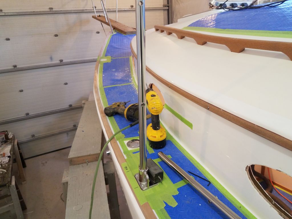
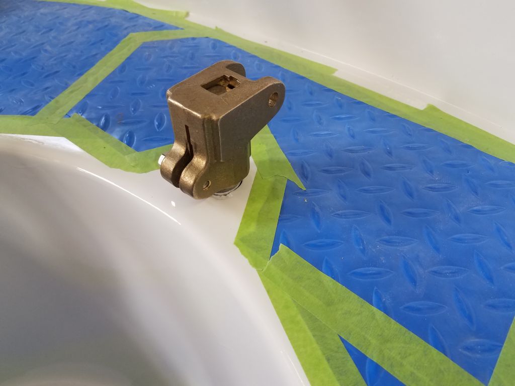
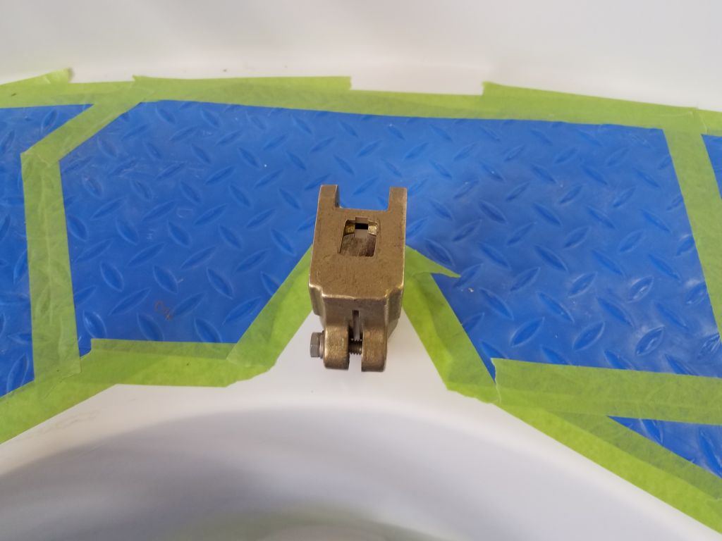
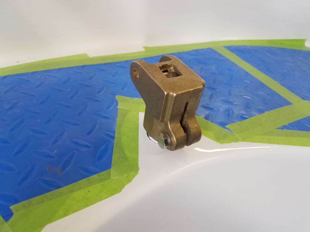
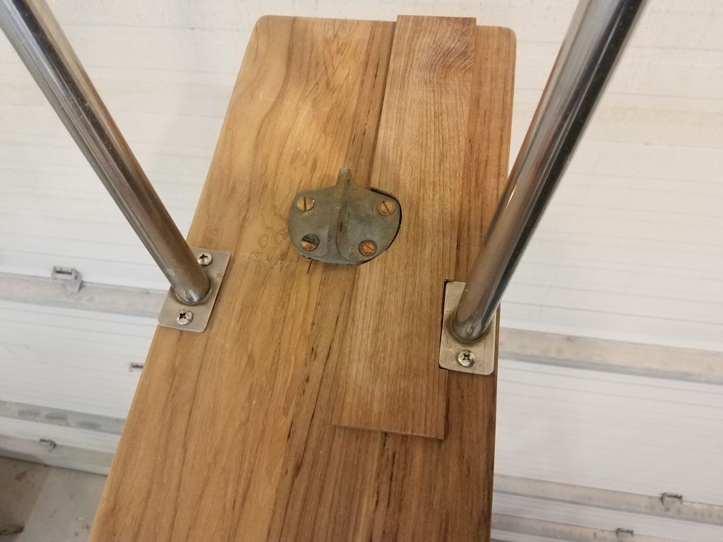
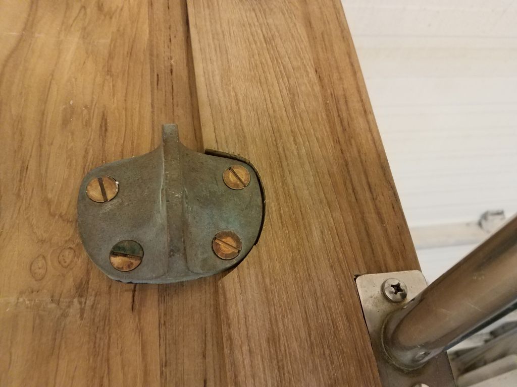
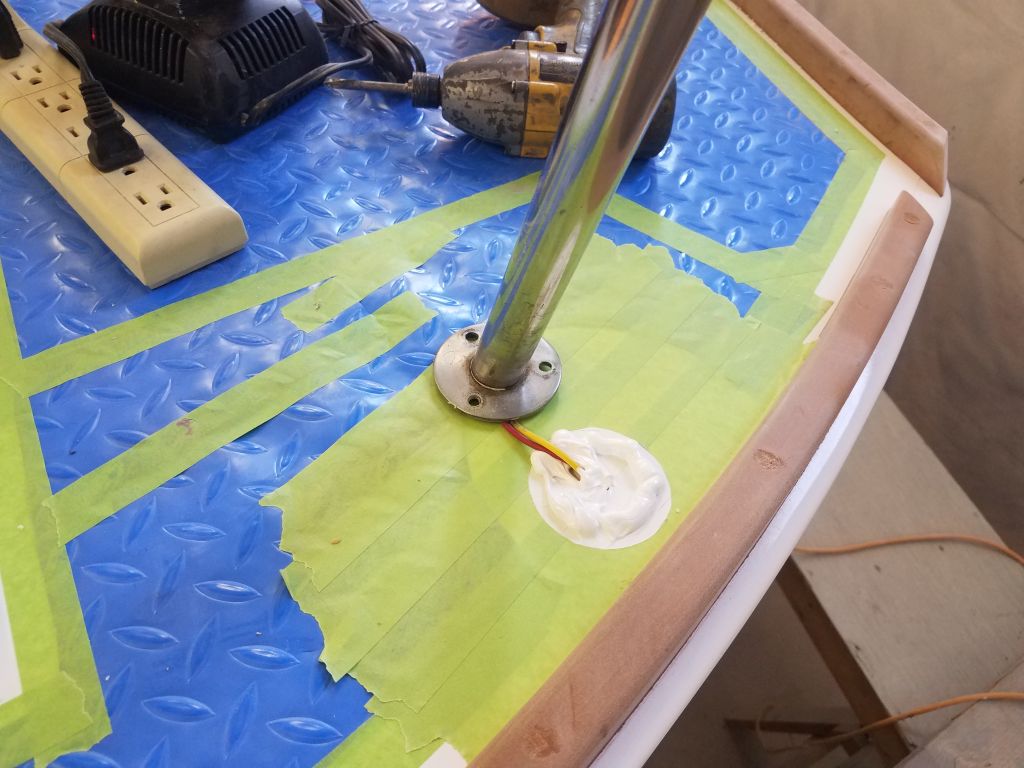
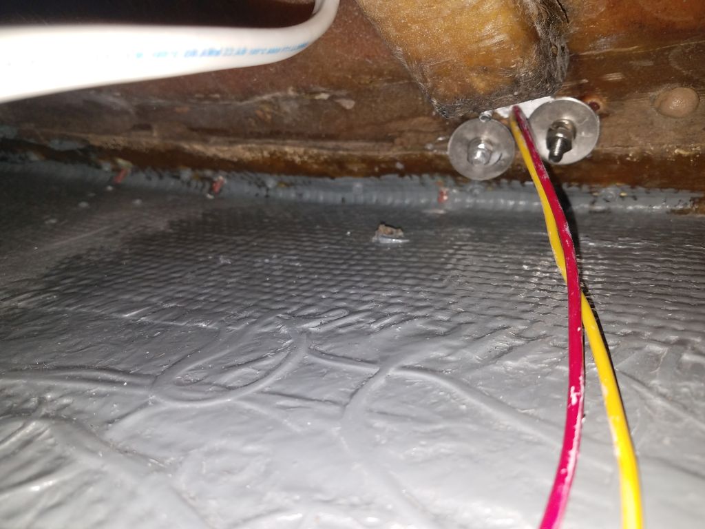
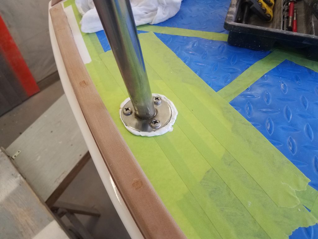
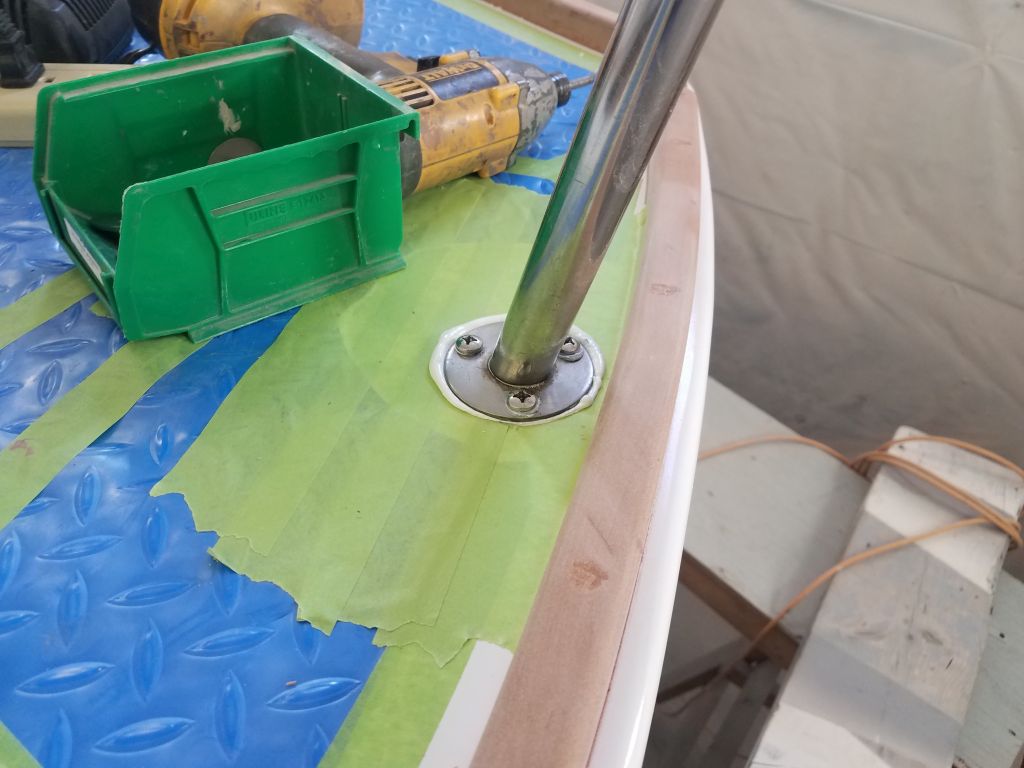
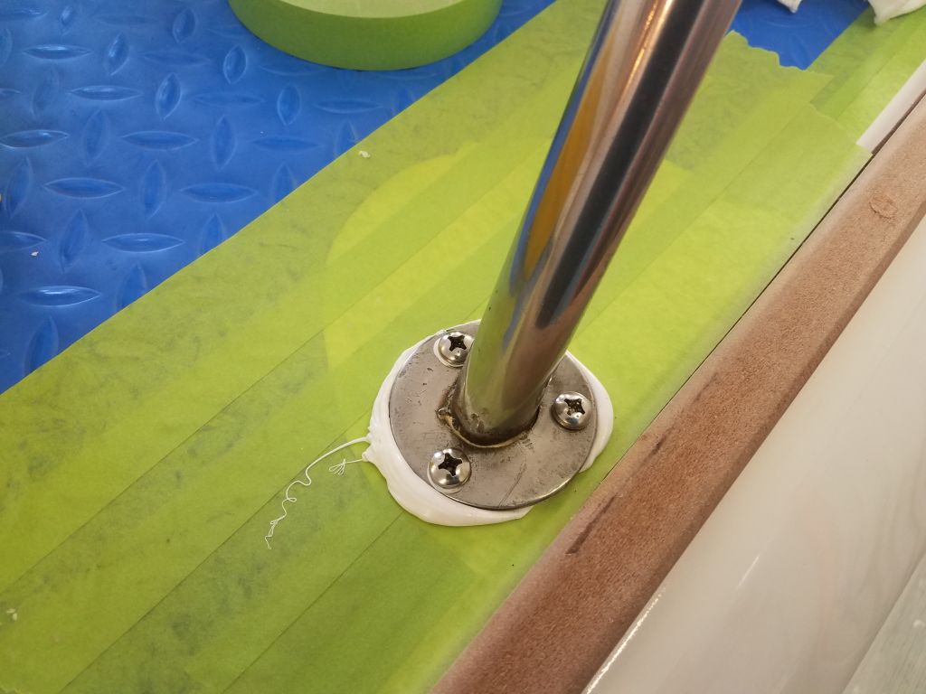
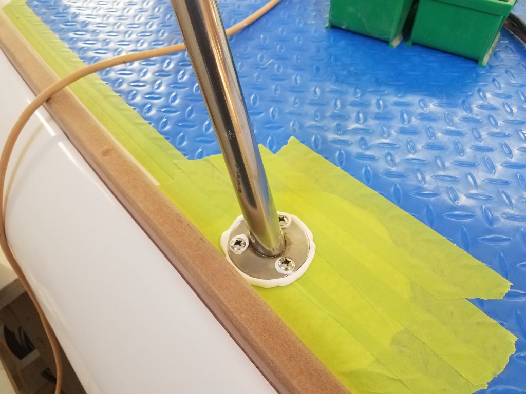
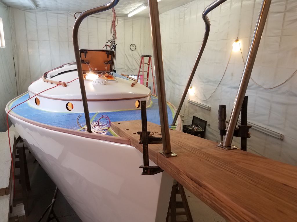
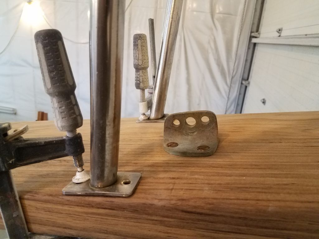
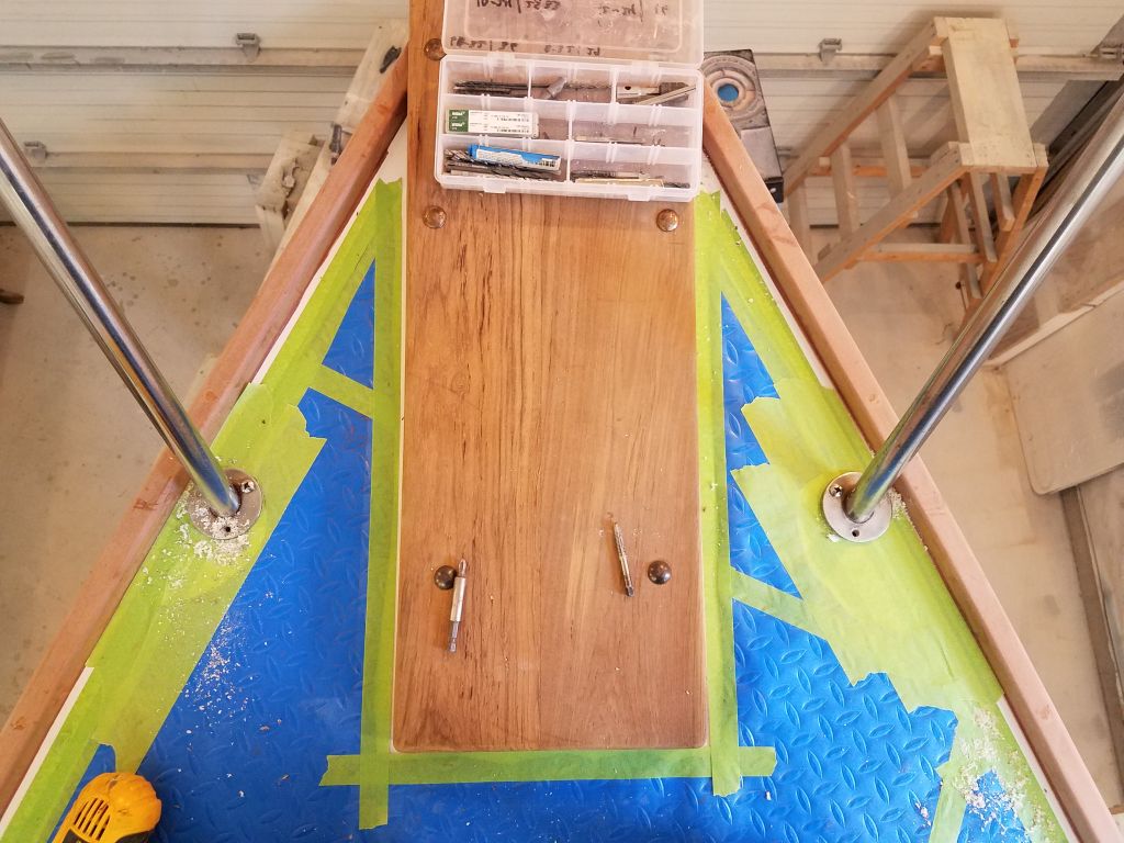
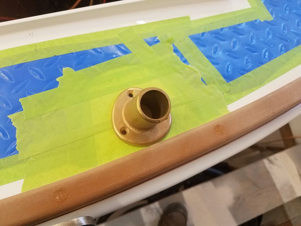
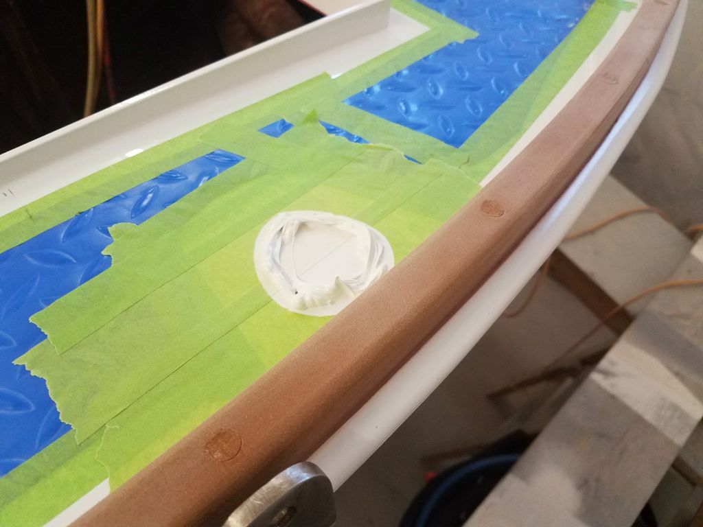
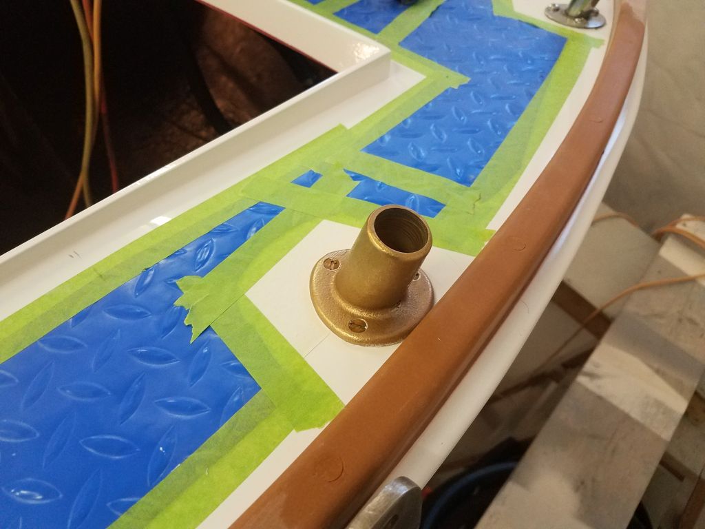
To round out the day, I worked on a couple small hardware installations on the poop deck, starting with a new bronze flagpole socket. These fasteners passed through solid fiberglass, so I could complete all steps of the installation now.

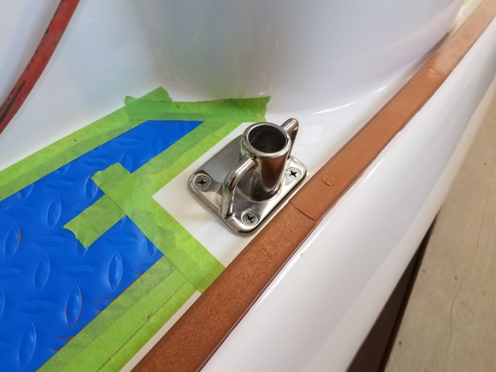
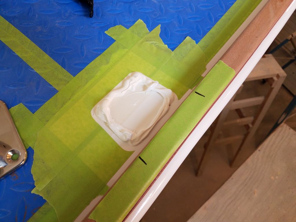
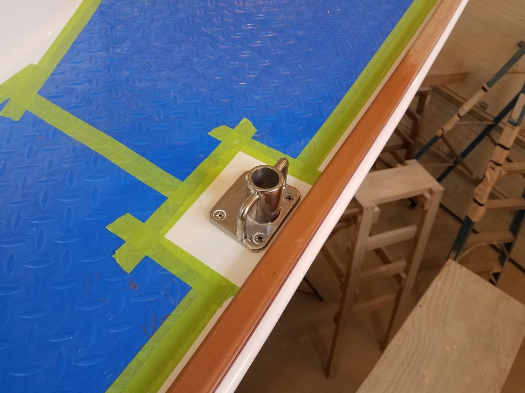
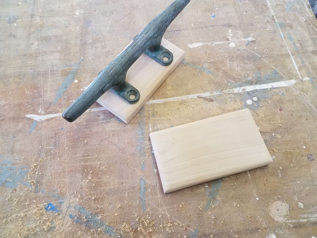
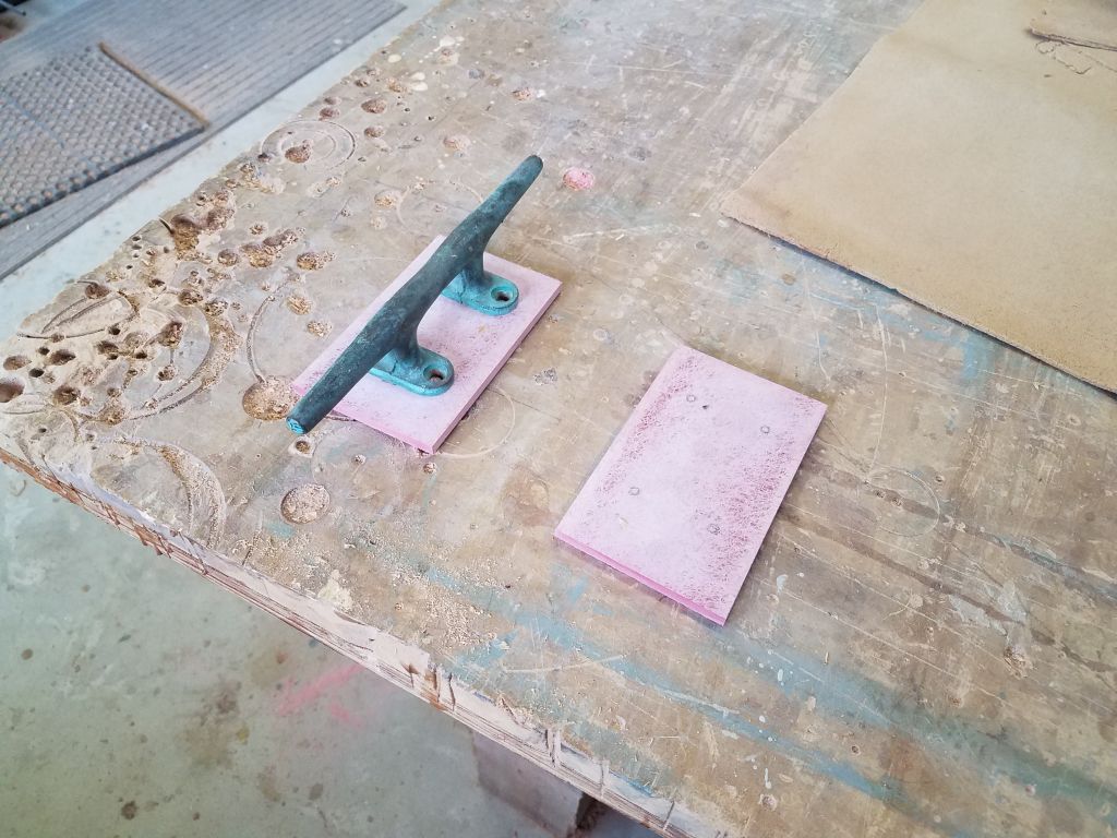
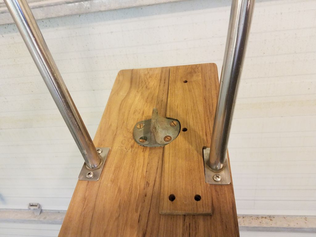
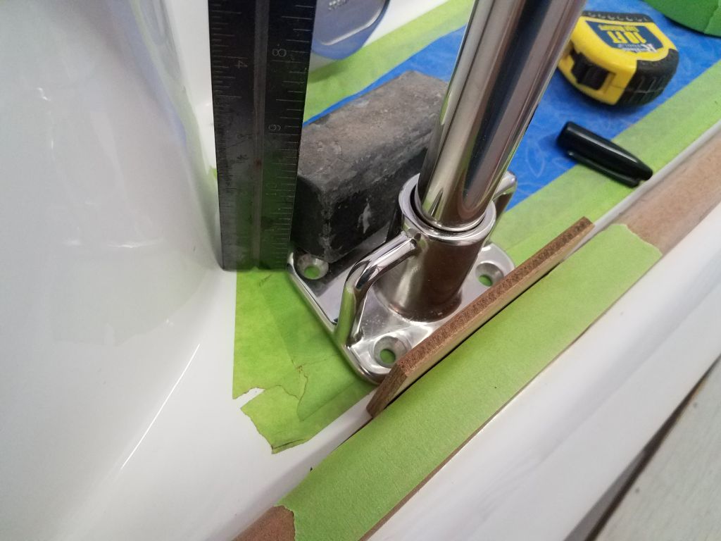
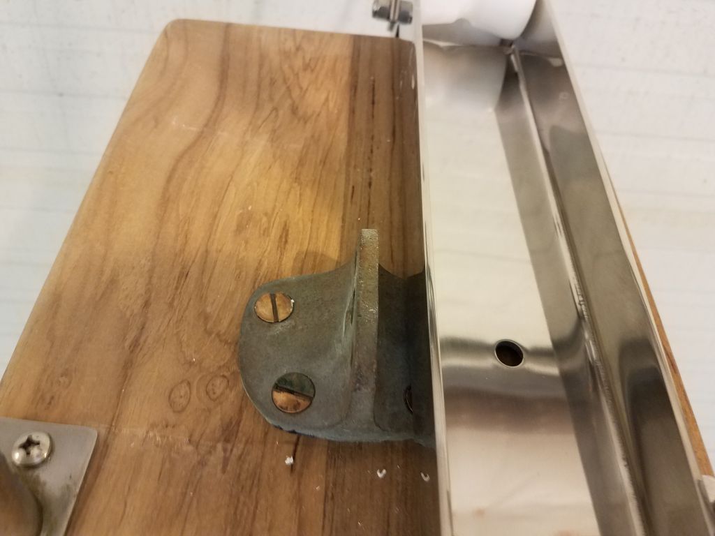
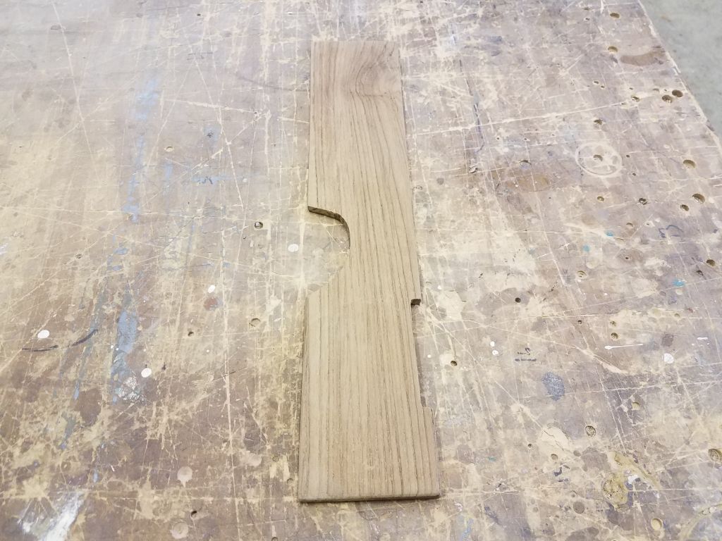
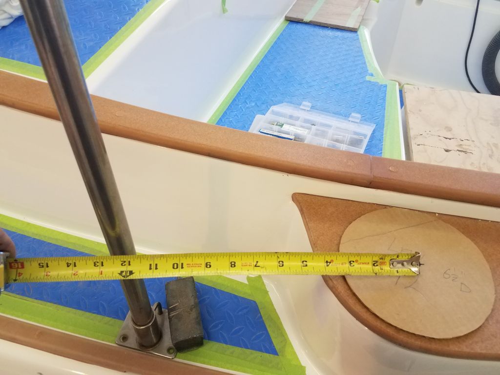
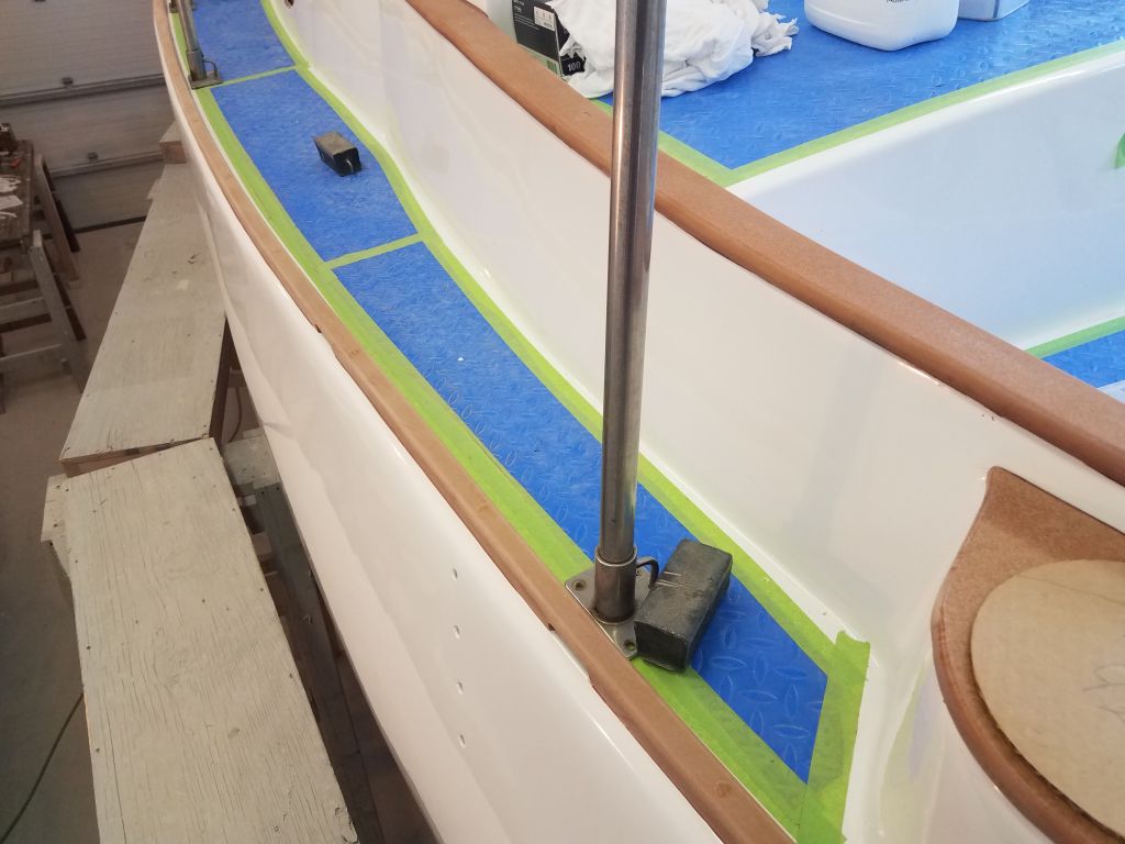
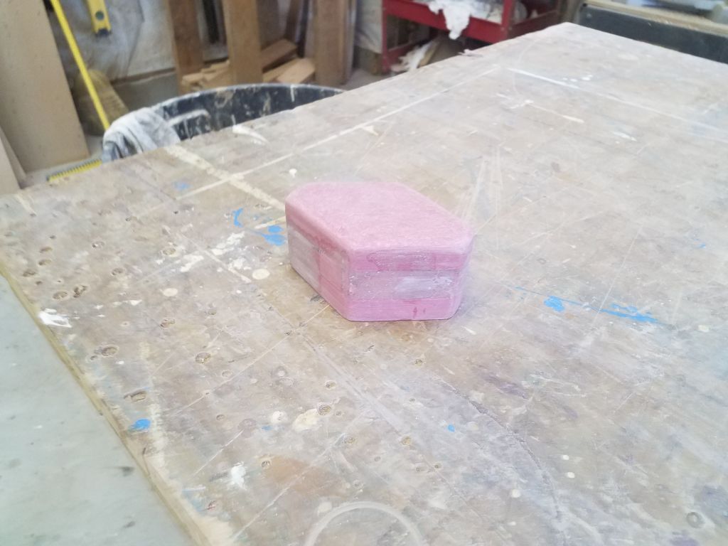
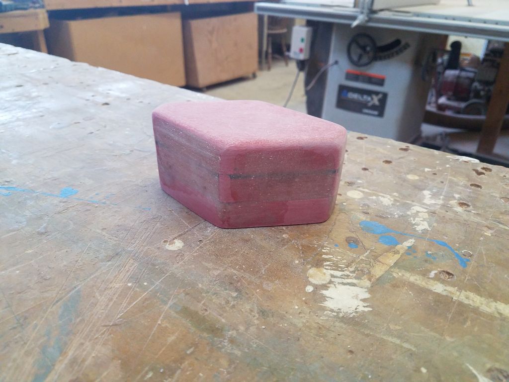
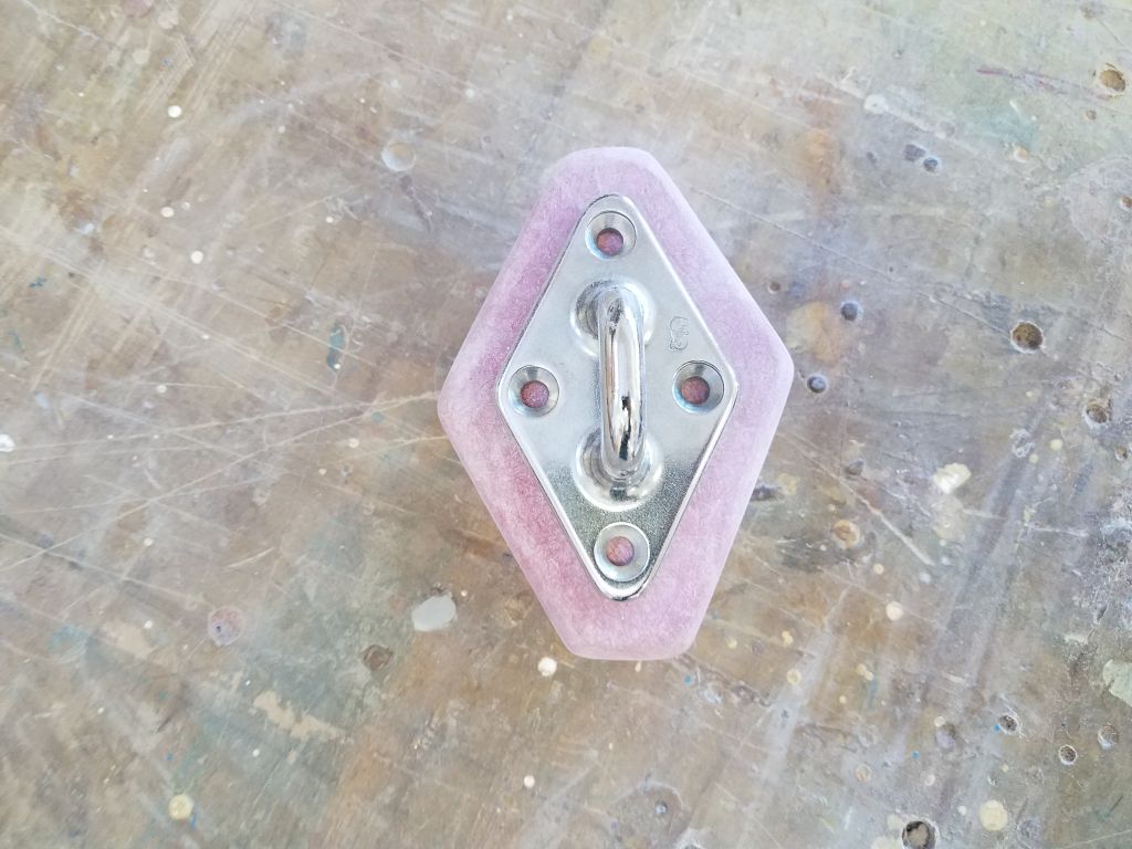
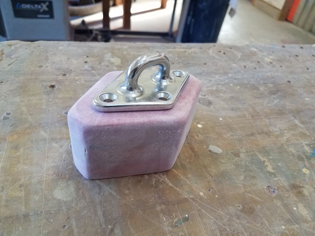
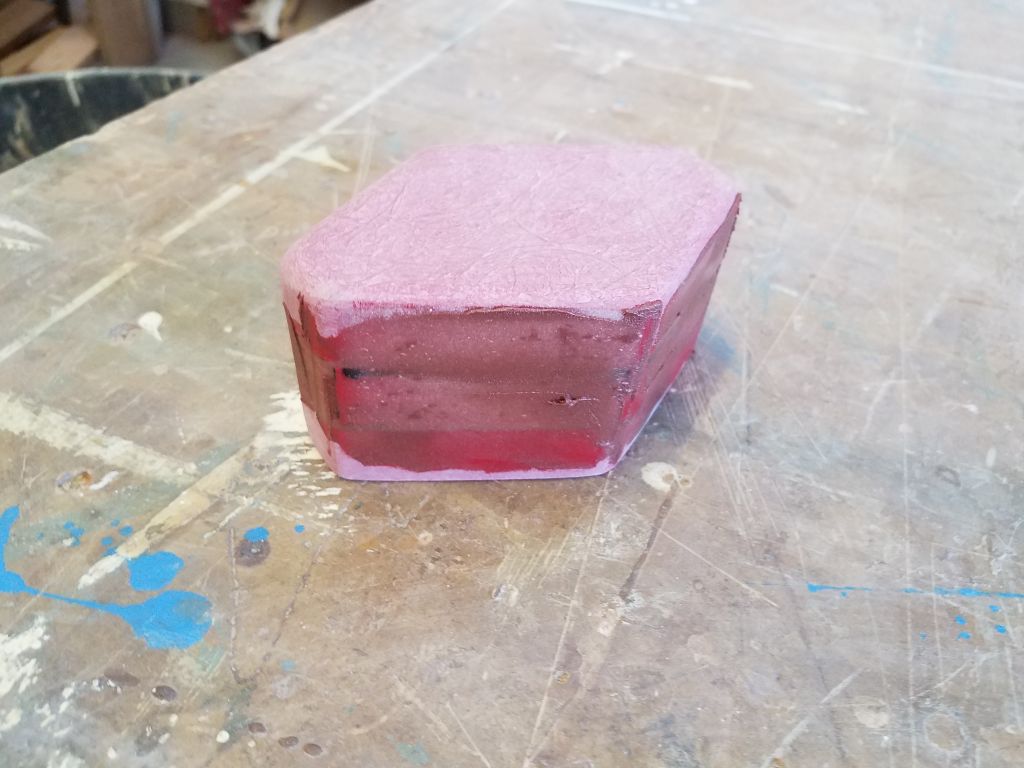
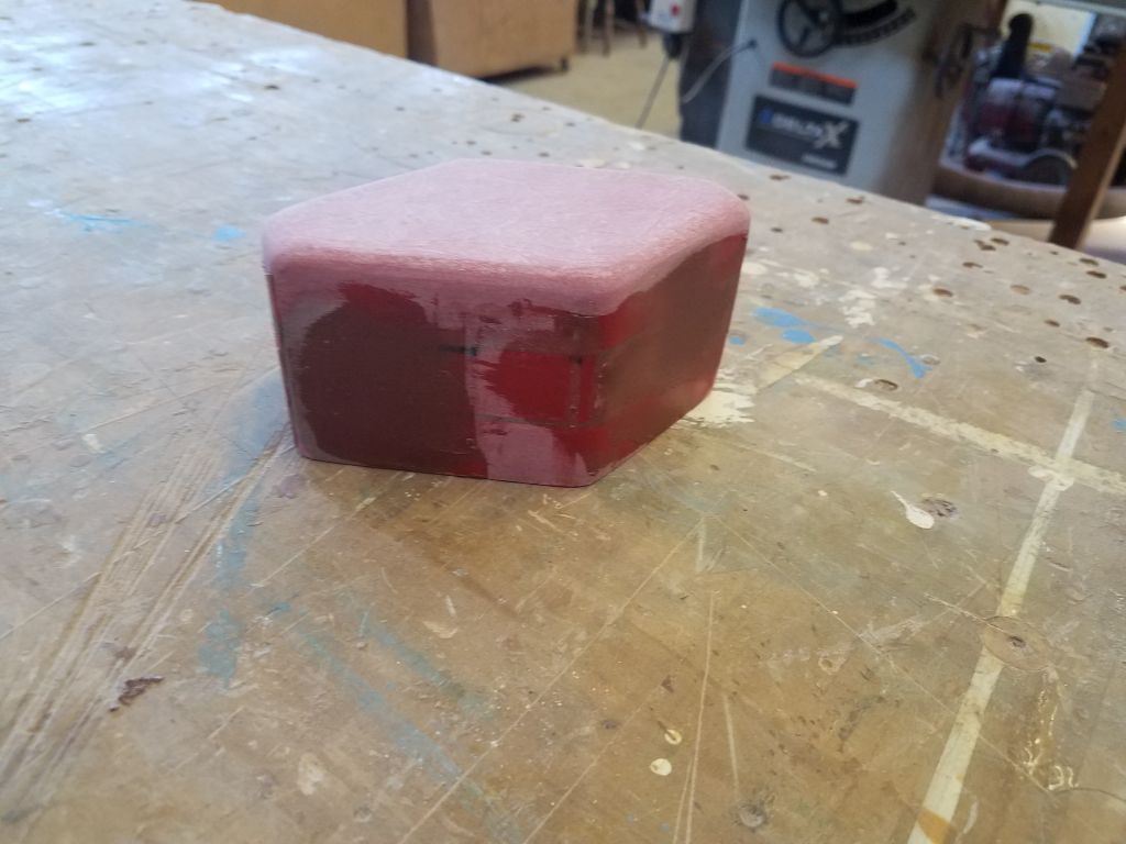
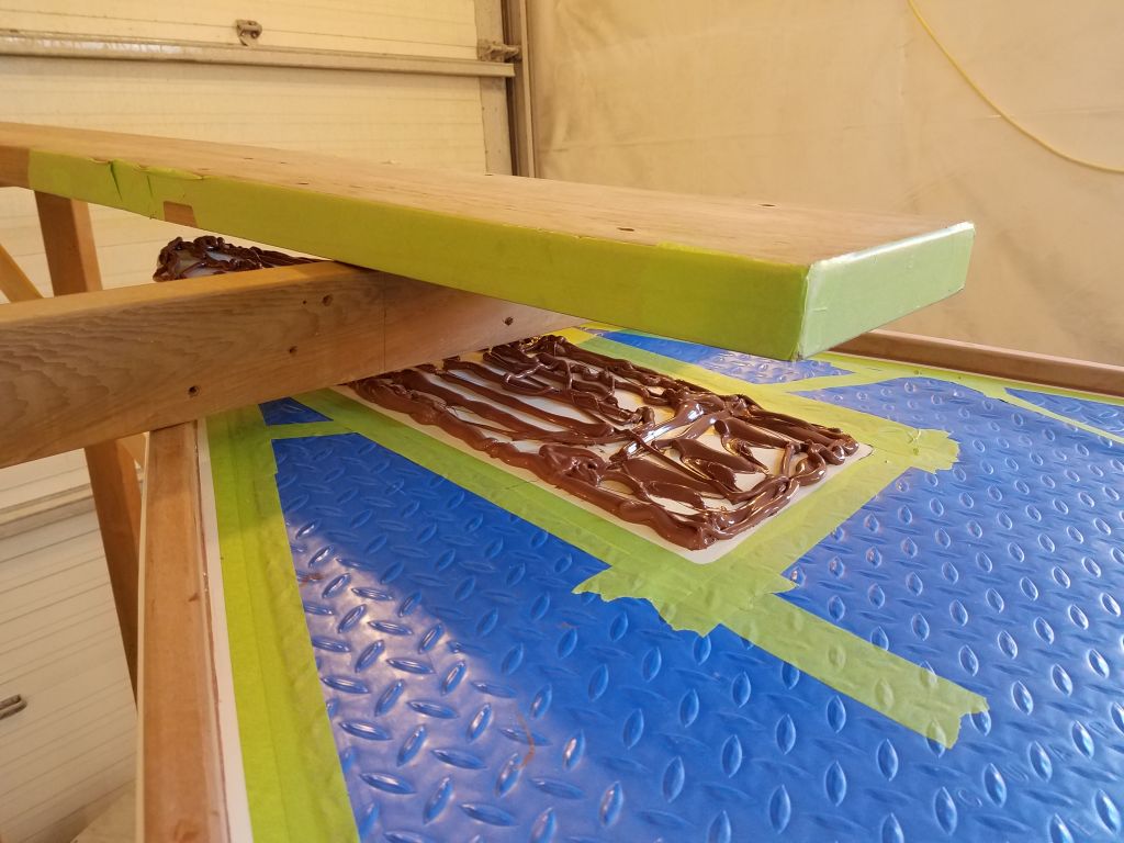
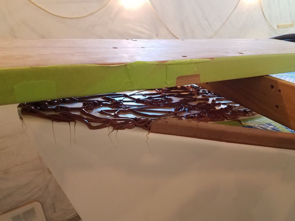
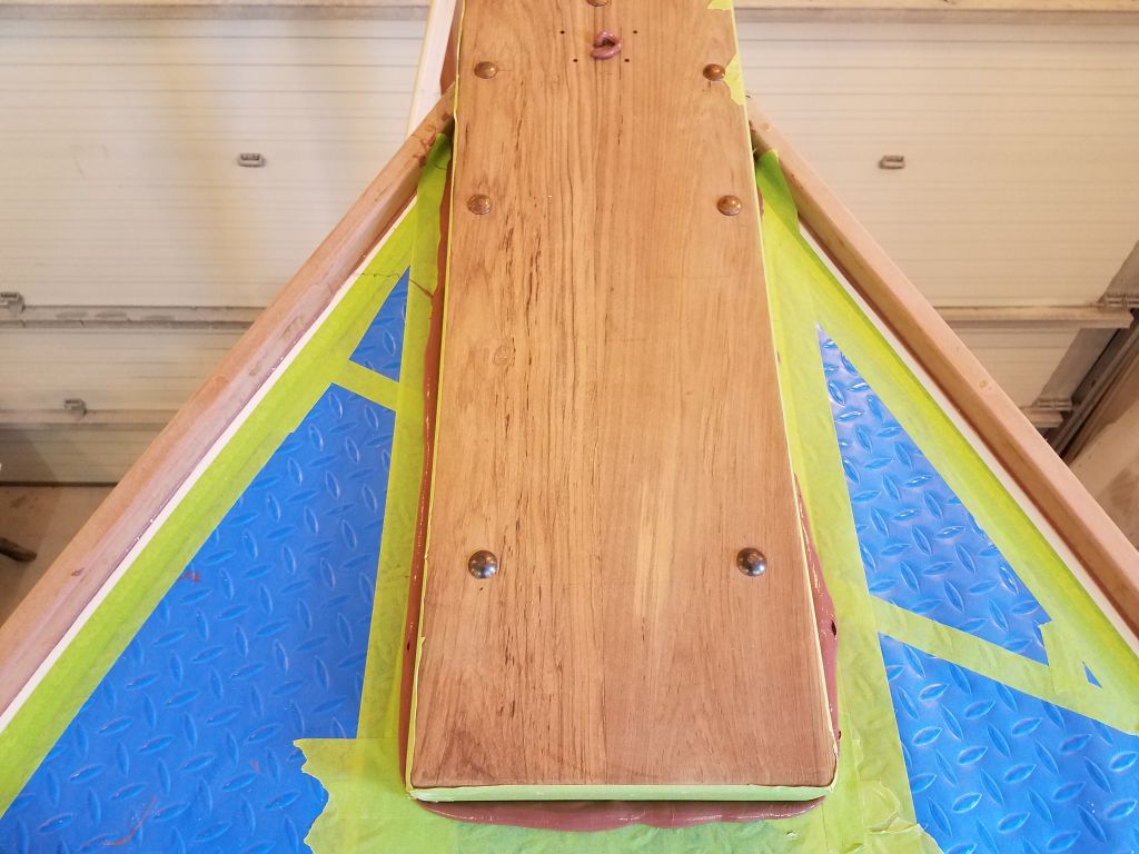
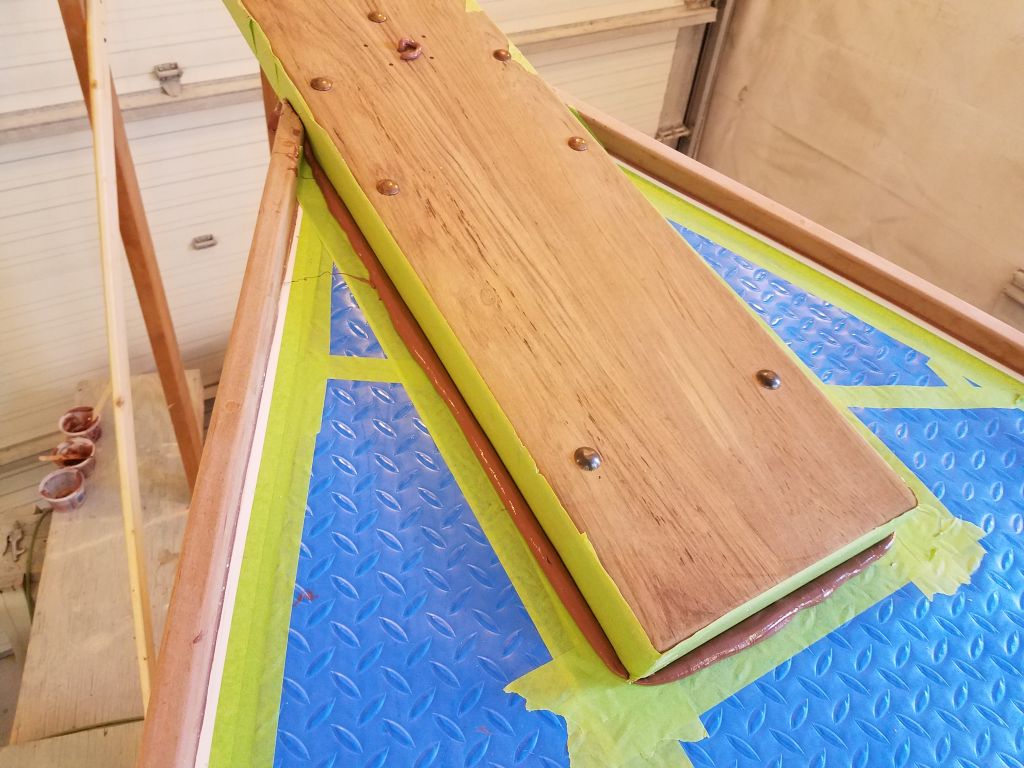
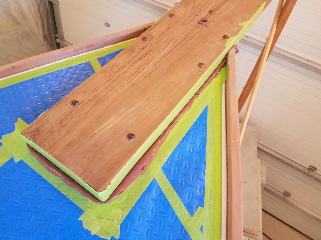
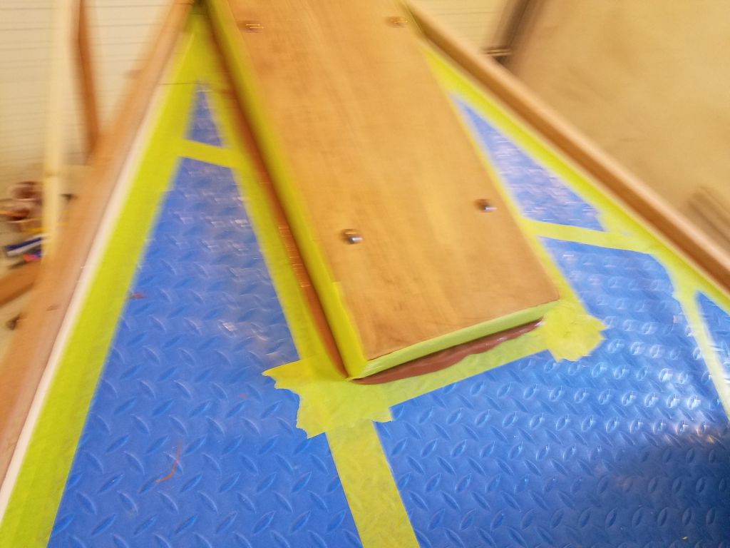
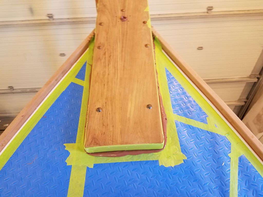
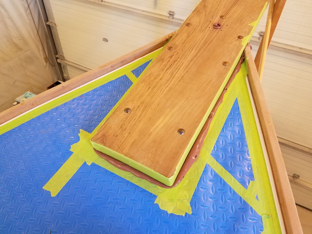
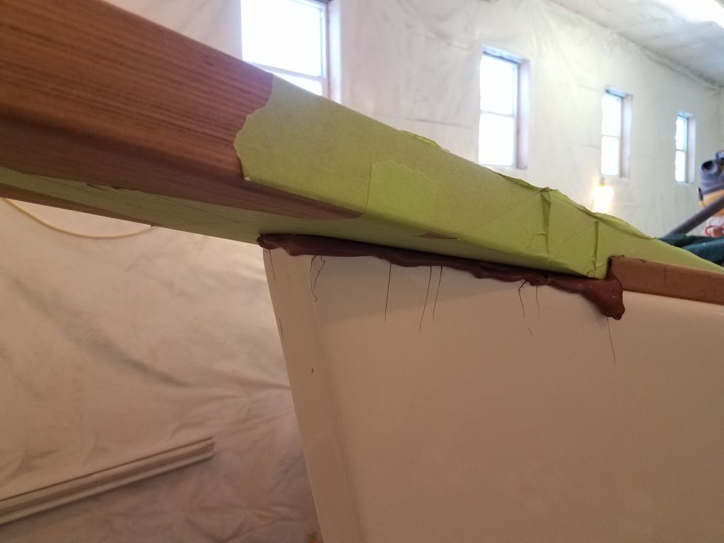
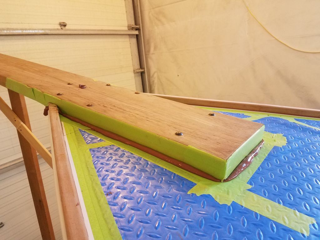
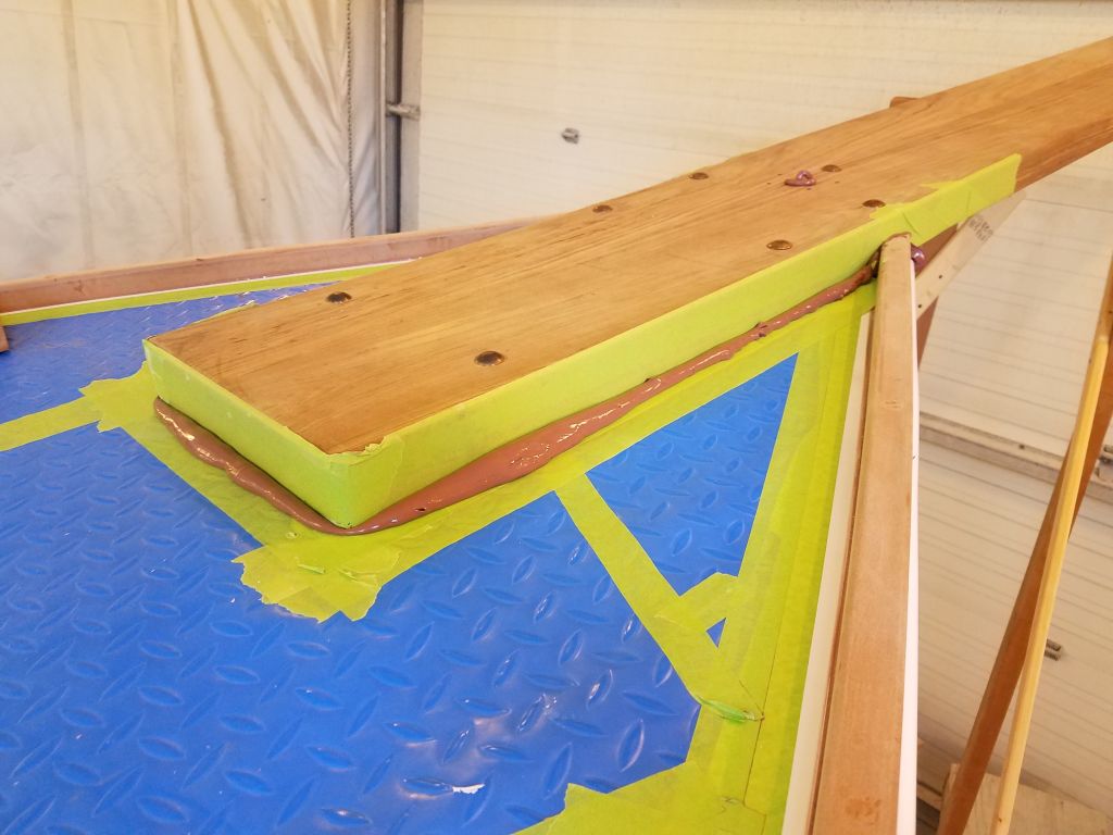
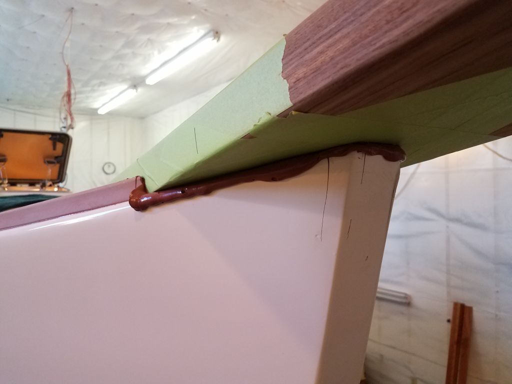
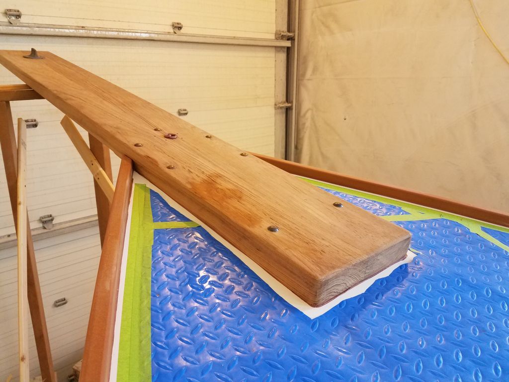
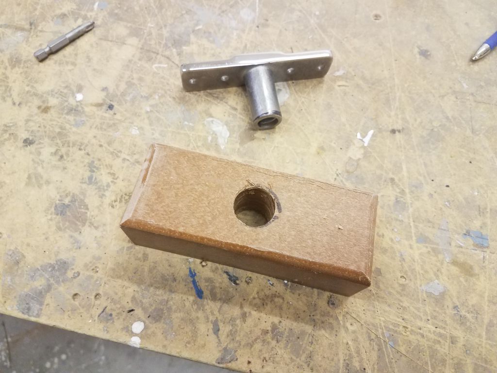
The owner requested an oarlock socket on the starboard side of the transom, and I’d recently obtained the hardware. To raise the socket above the toerail, I milled a small riser block to fit from some of the plastic lumber used on deck. I played around with mounting locations for a minute or two, but I needed to await installation till I could also address the final location of the stern chocks, and in any event I was out of time for now, so I left the oarlock uninstalled for the moment.
Total time billed on this job today: 7.75 hours
0600 Weather Observation: 18°, clear. Forecast for the day: Sunny, 31°