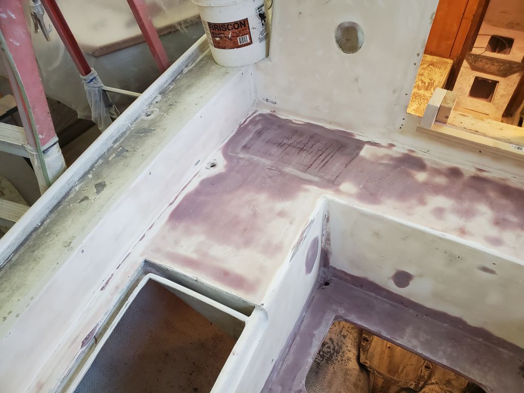
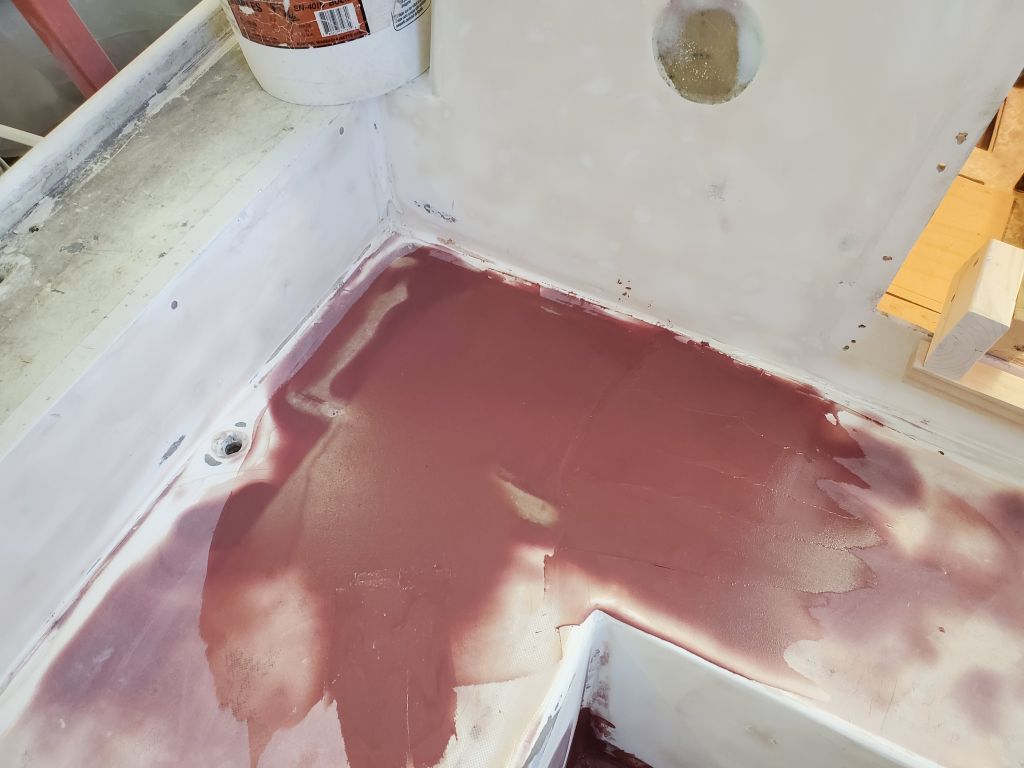
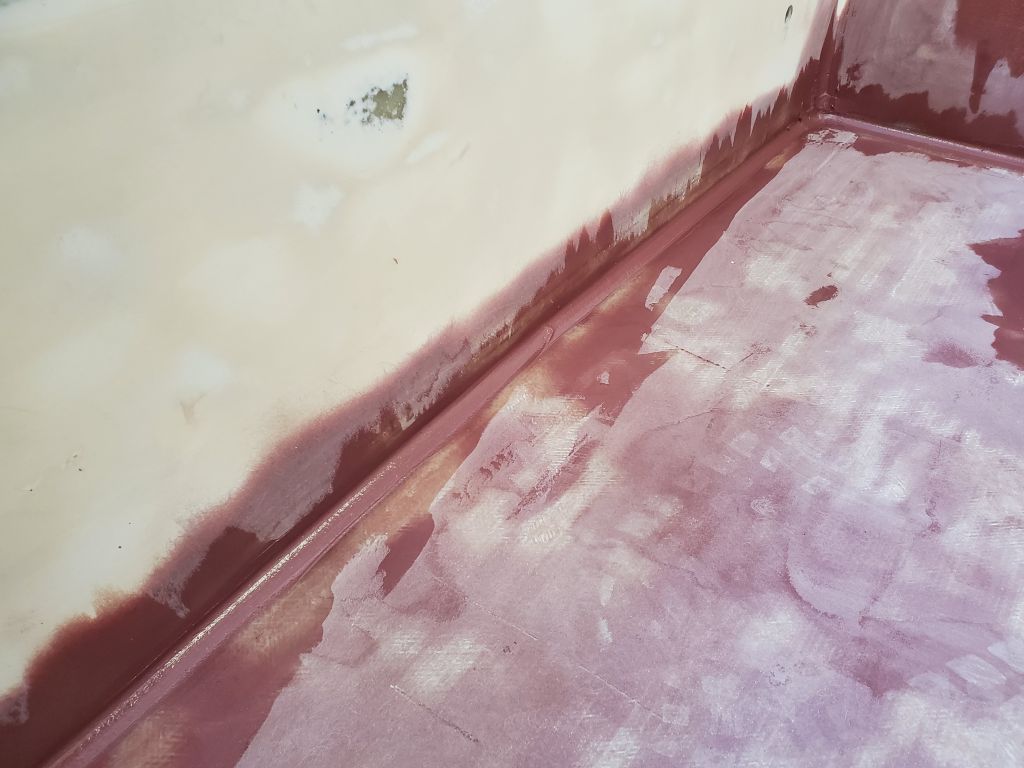
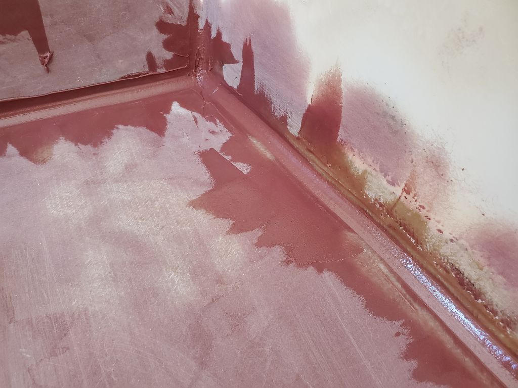
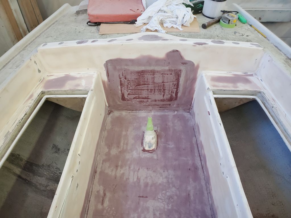
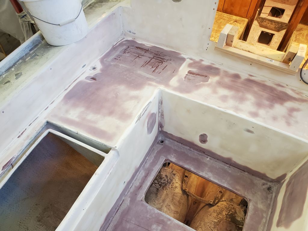
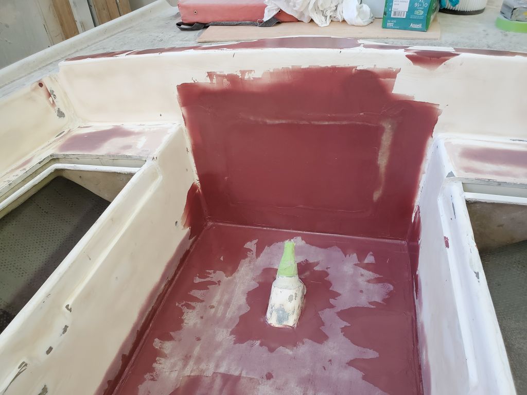
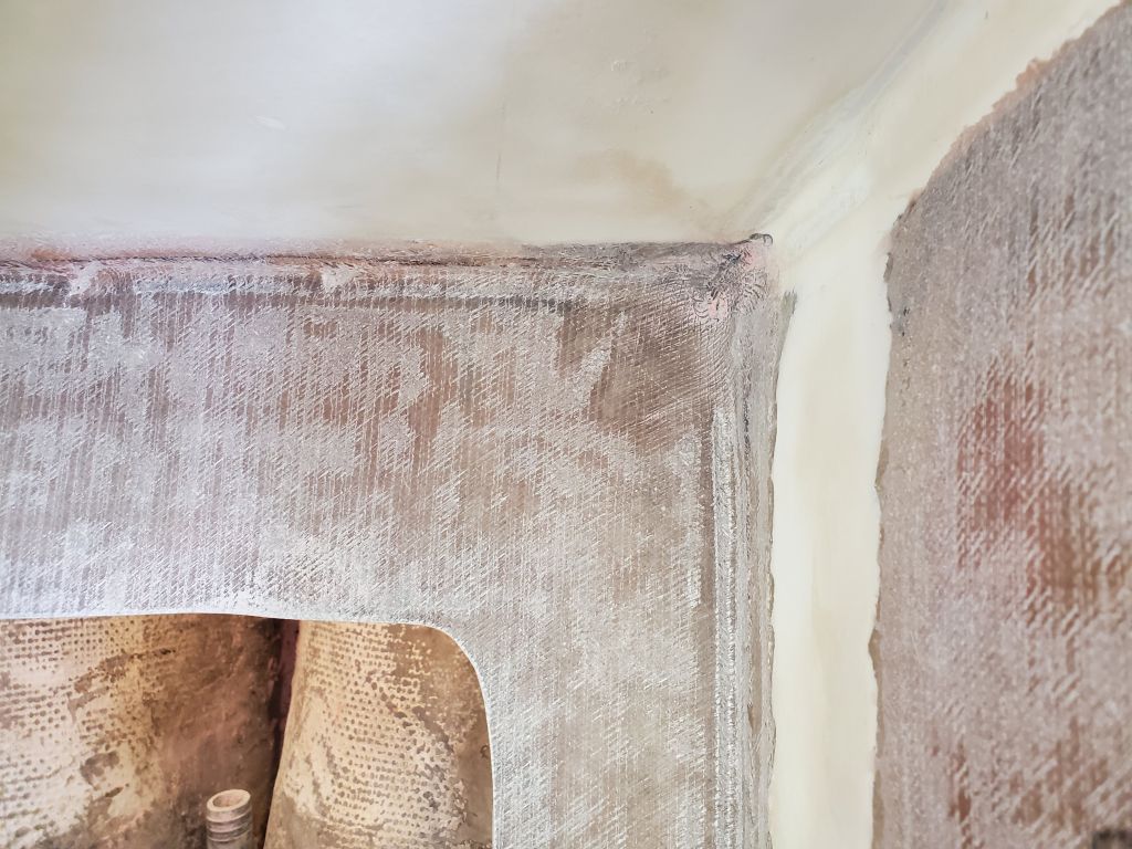
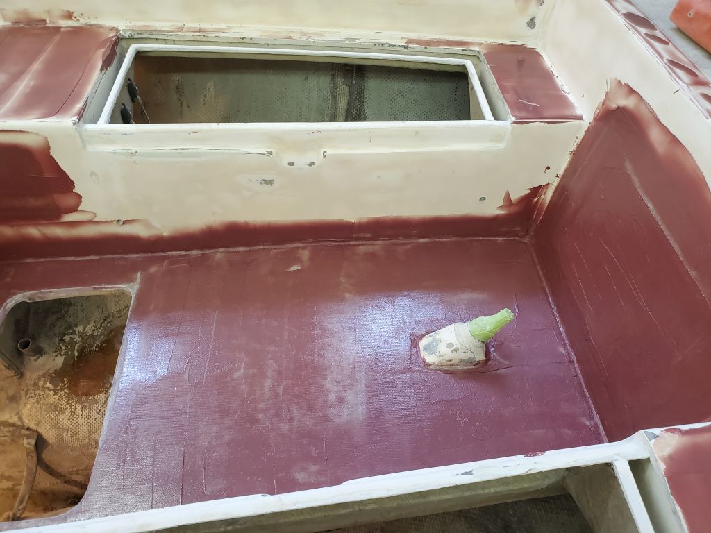
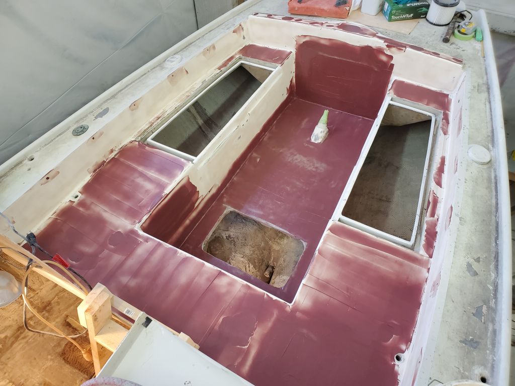
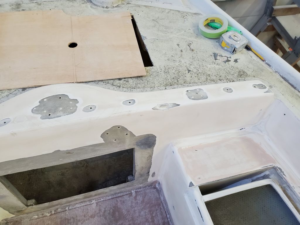
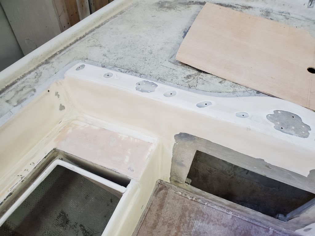
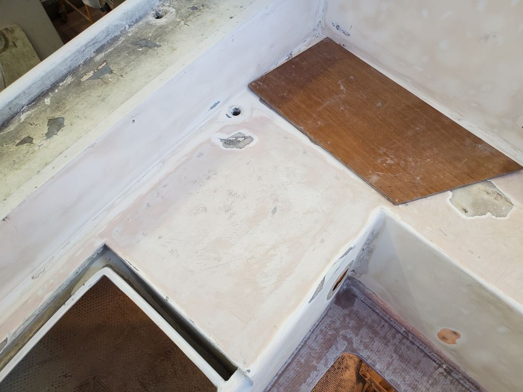
Back to work in the cockpit, once more, for another round of sanding. Now I’d reached the point where I was only using a finer grit of sandpaper on the patches as things inched towards completion for this stage. The two largest repairs–to the icebox hatch and the lazarette opening–would require some additional work to take care of remaining low spots, but most of the rest of the cockpit was in pretty good shape, other than some fine-tuning.
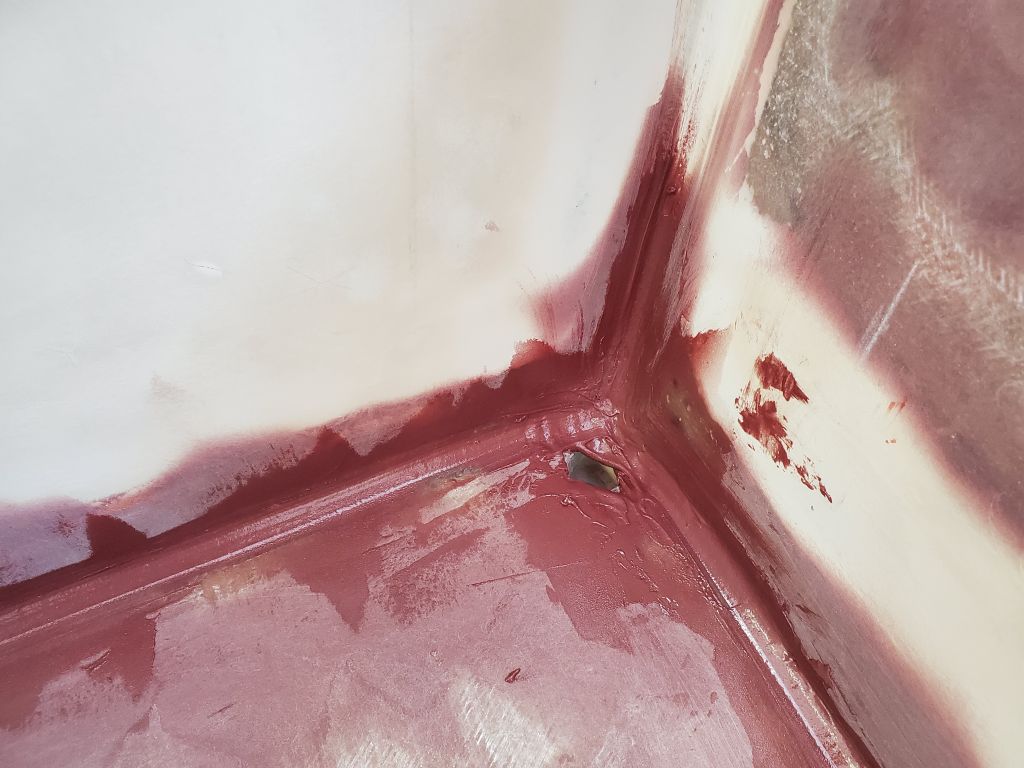
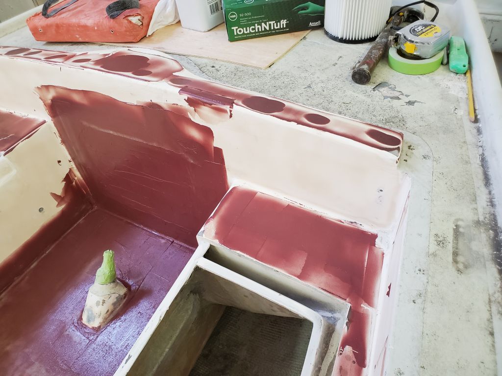
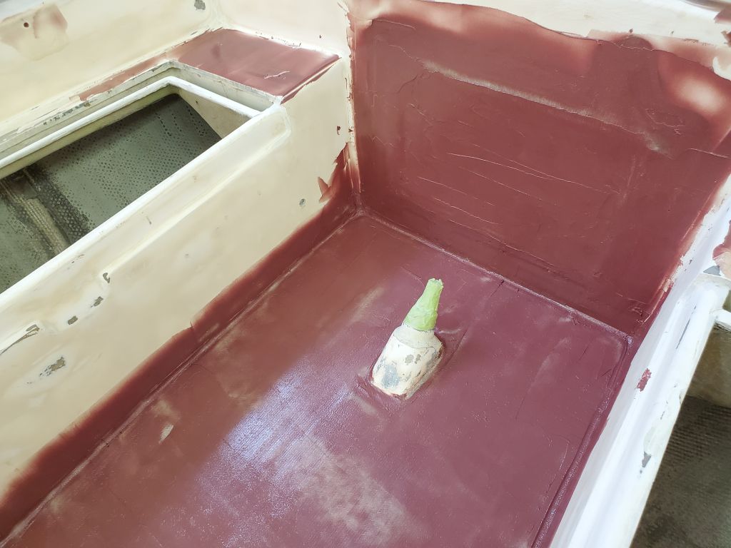
After cleanup, I applied additional fairing compound to the two larger patches, then focused mainly on forming new fillets at the edges of the cockpit sole to create smooth curves where the cockpit well met the sole, and at the corners, particularly the forward corners at the scuppers. Finger-sanding loomed ahead.
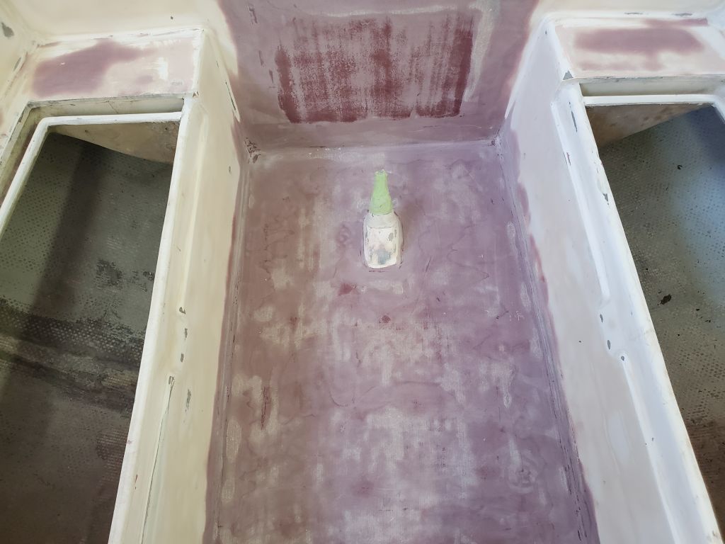
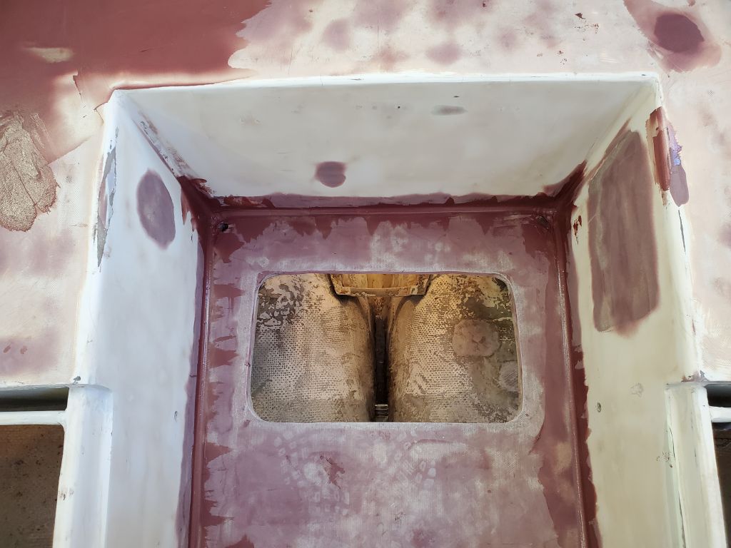
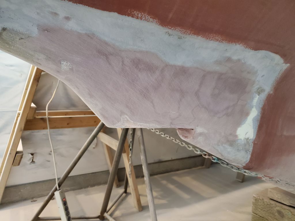
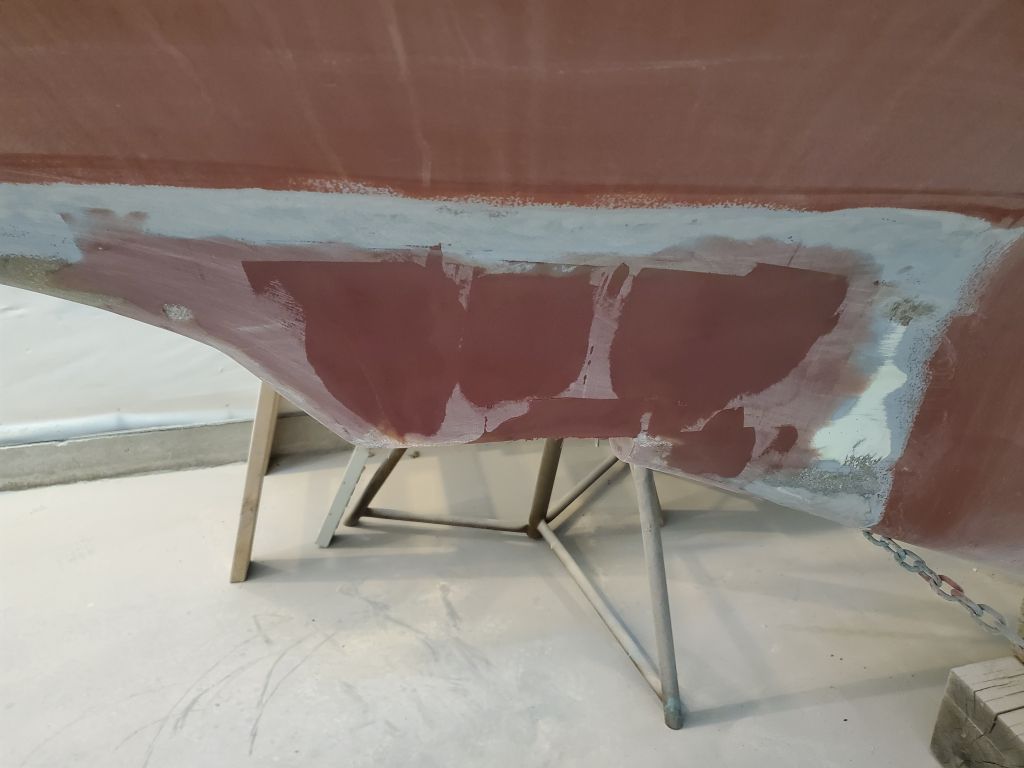
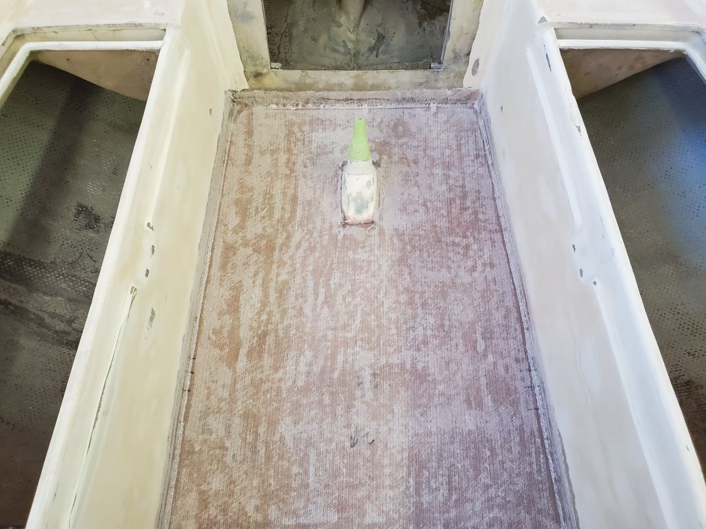
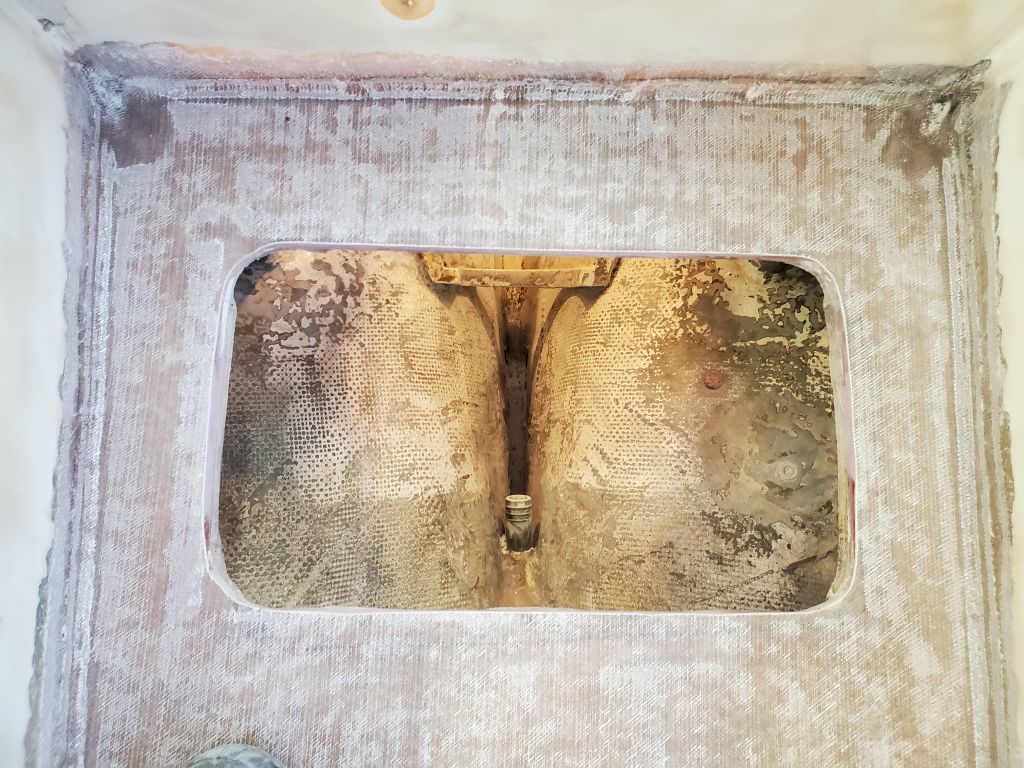
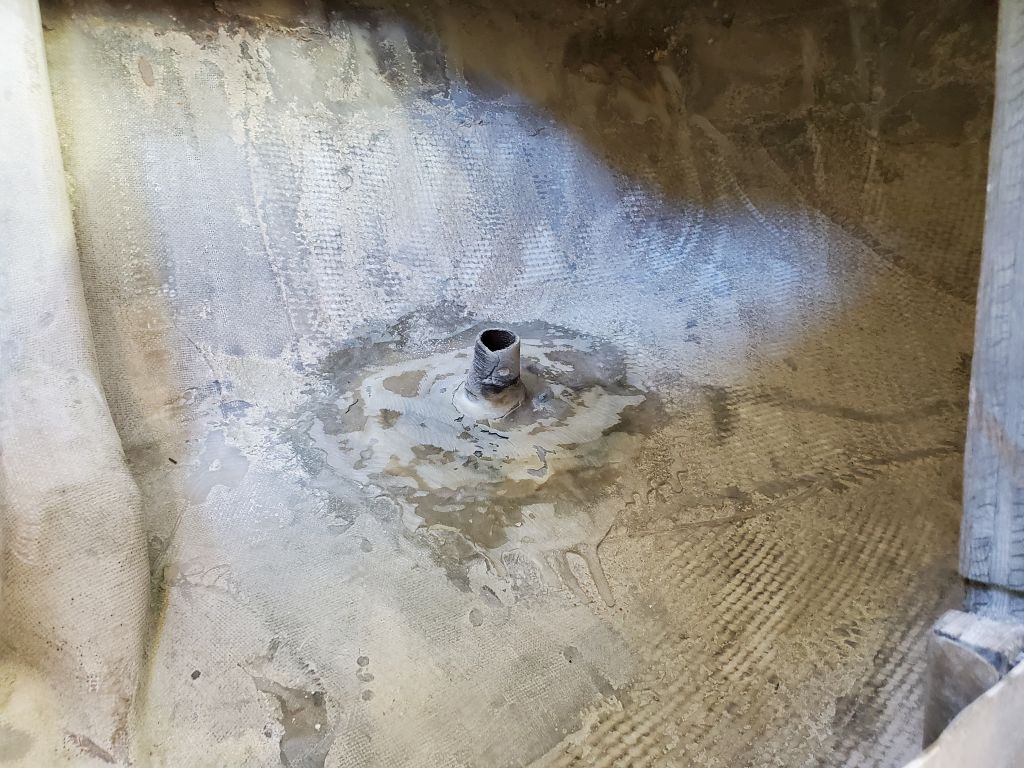
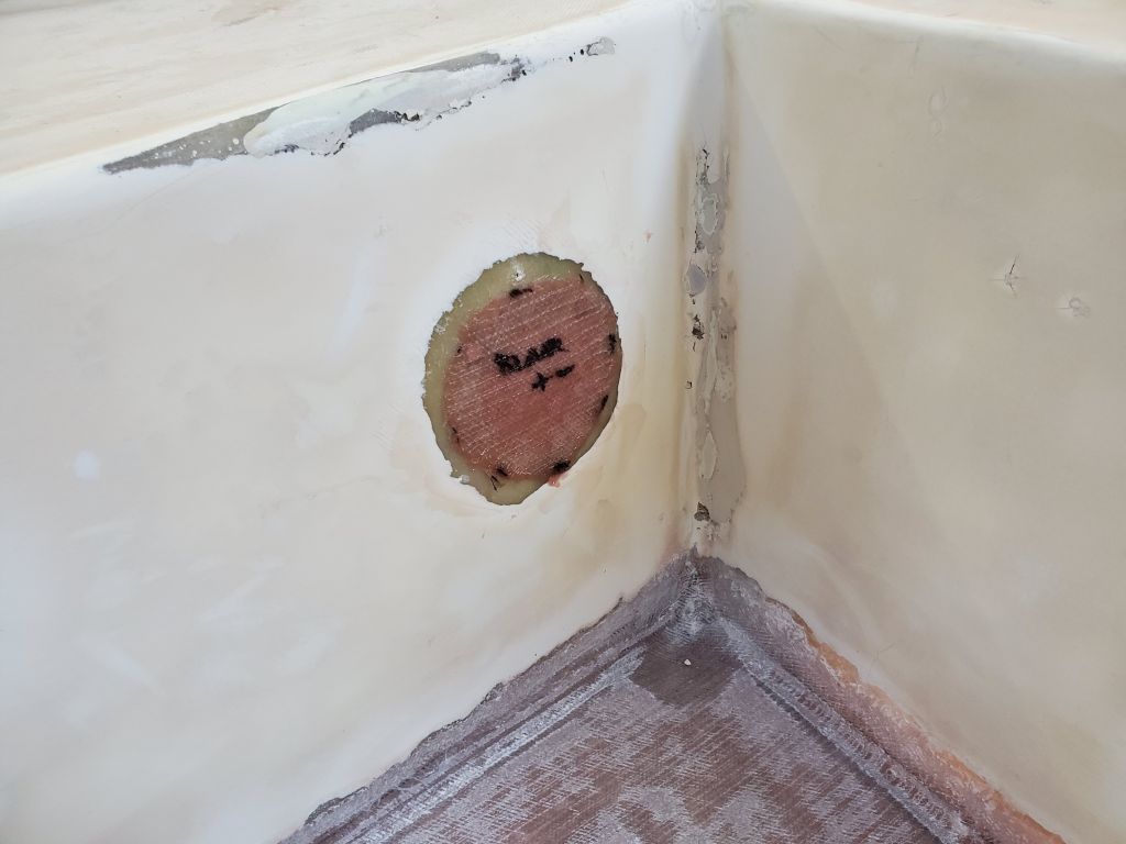
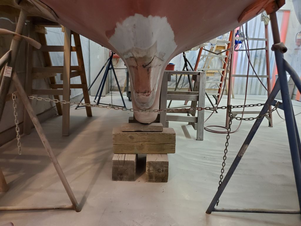
The transducer housing required one more light sanding, by machine and then by hand, after which I called this complete and ready for transducer installation (later in the project once the bilges and interior had progressed somewhat) and paint.
With the approaching end of the substantial cockpit structural repair work and surface prep, I looked forward to getting going on the interior paint, which would be the next focus after an intensive cleaning session. Most of the remaining jobs on the work list for now required that the cabin, lockers, and bilges be painted first.
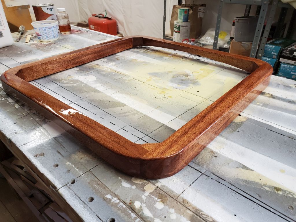
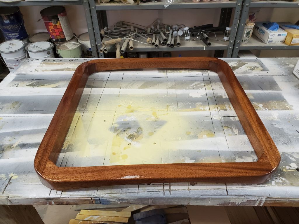
For now, I wrapped up the day’s work with another light sanding and third coat of varnish on the forward hatch, and spent the afternoon working on another ongoing project at the shop.
Total time billed on this job today: 4 hours
0600 Weather Observation: 9°, partly clear. Forecast for the day: Becoming mostly sunny, 24°.
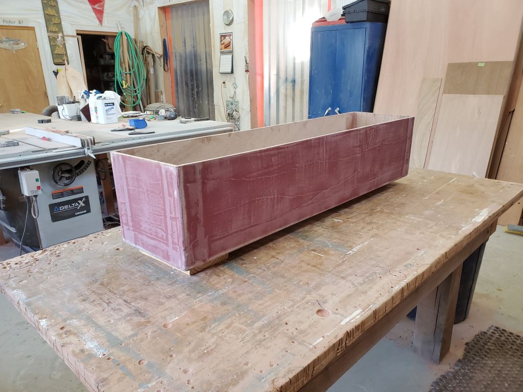
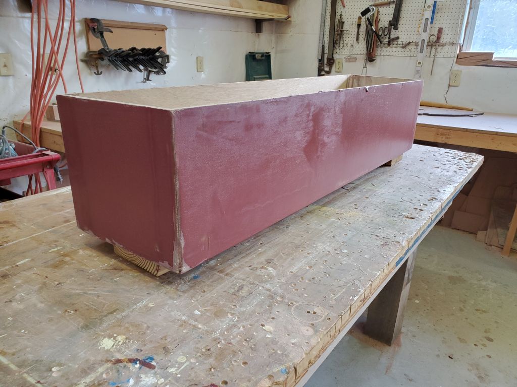
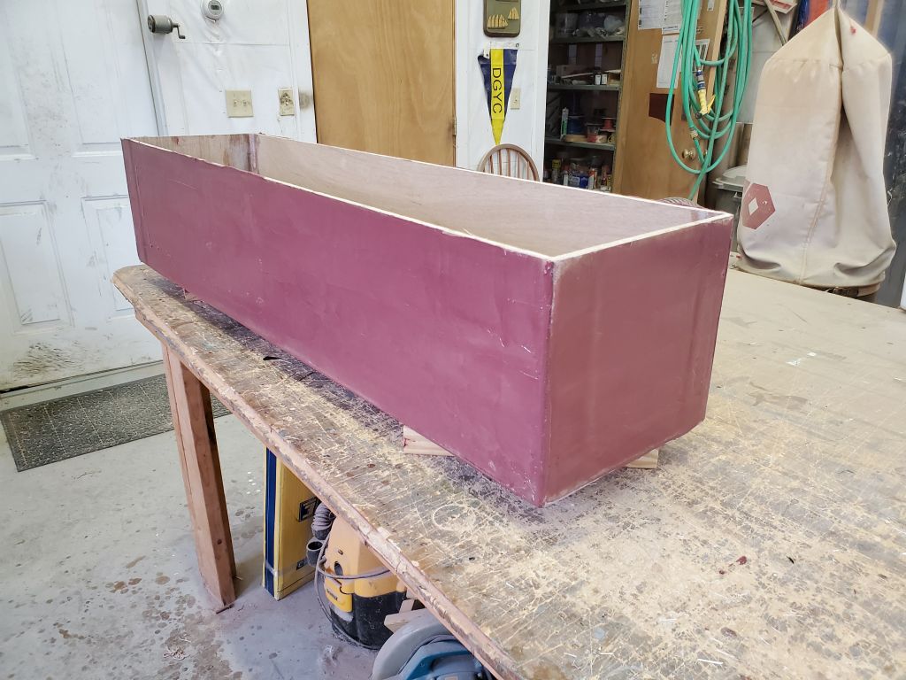
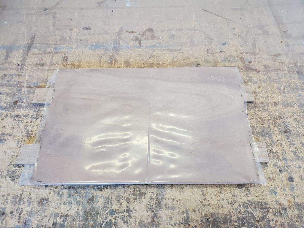
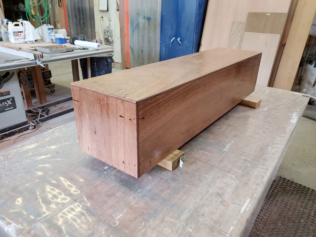
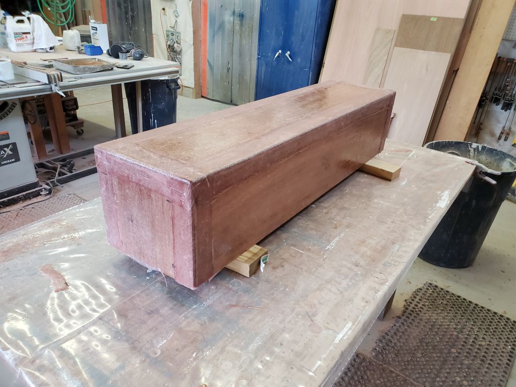
After lightly sanding the first round of fairing filler on the deck box, I applied a second layer, this time using a wide trowel to span the entire height of the box. Because the box was fairly lightweight, I’d noted the last time that tended to move about when working on the sides, so now I filled it with some scrap lumber to help weight it down; this worked well to allow me to trowel effectively.
Total time billed on this job today: .75 hours
0600 Weather Observation: 0°, clear, 2″ or so of snow from yesterday. Forecast for the day: Sunny, 28°.
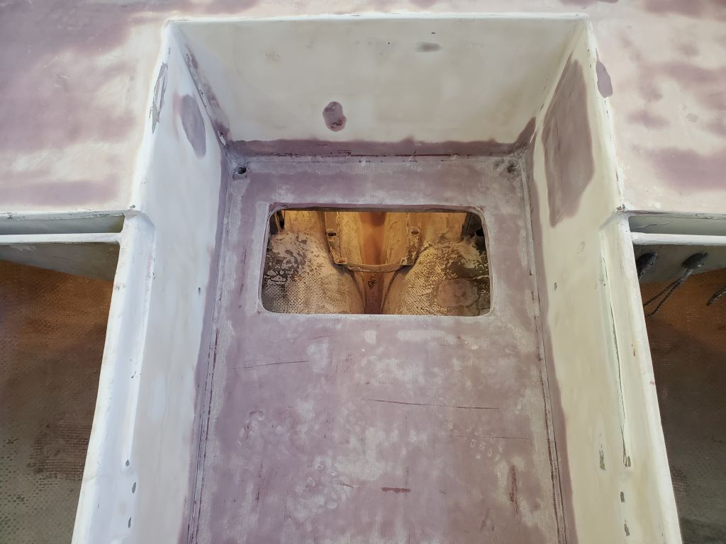
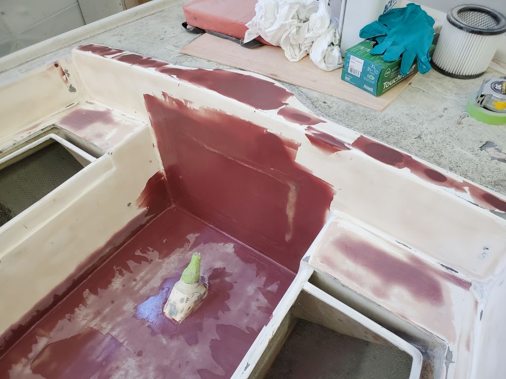
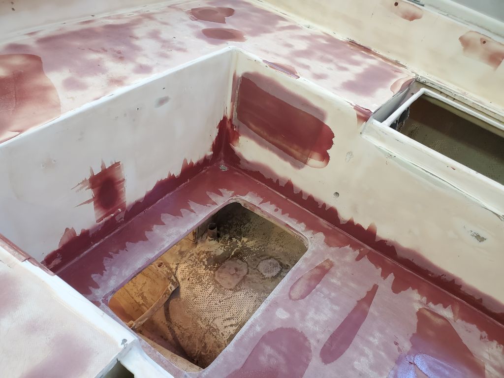
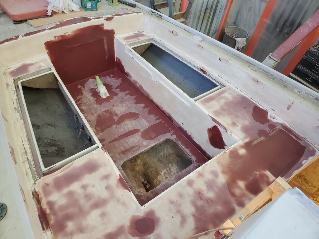
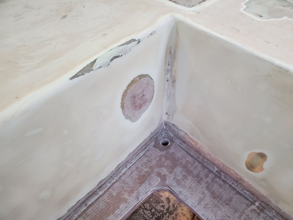
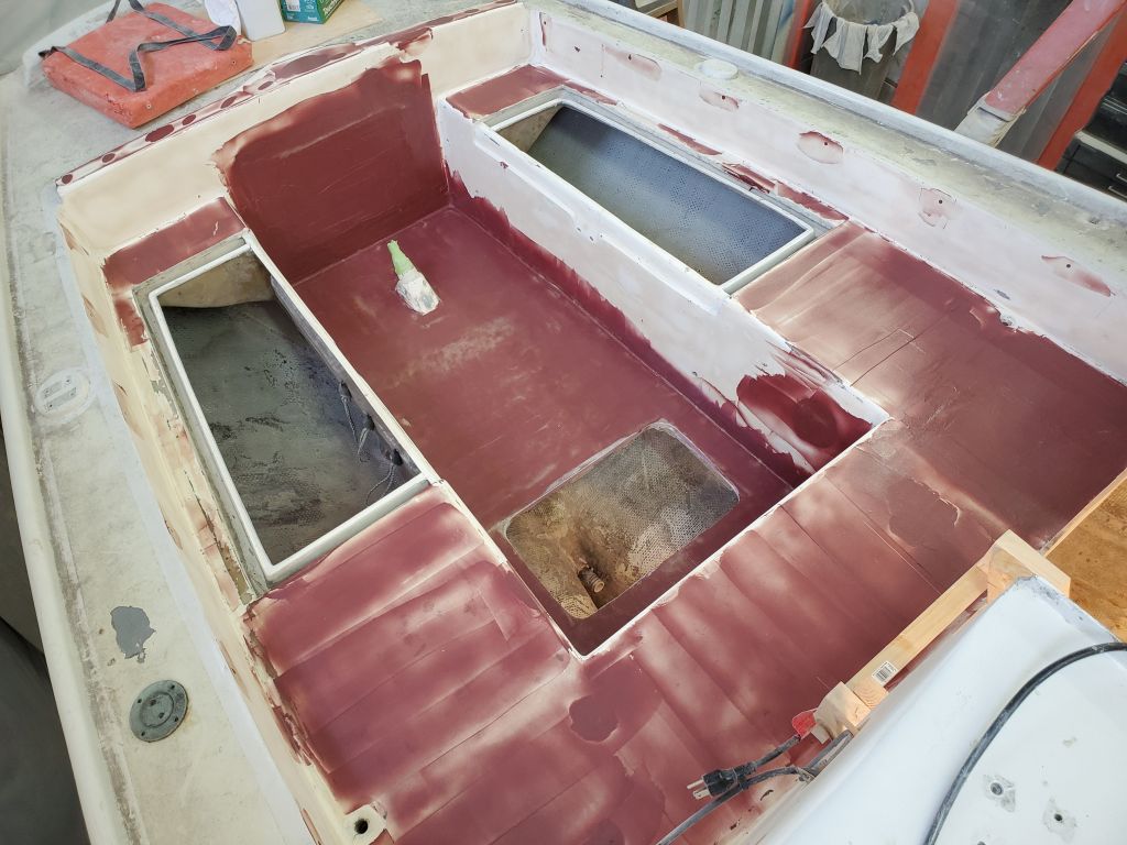
Back to work in the cockpit, I started off the morning with a round of sanding, cleaning up the first round of fairing filler in the cockpit areas and lightly sanding the fiberglass patches on the inside surfaces of the cockpit and icebox hatch.
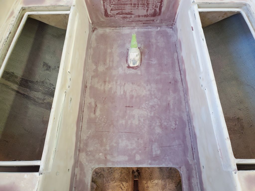
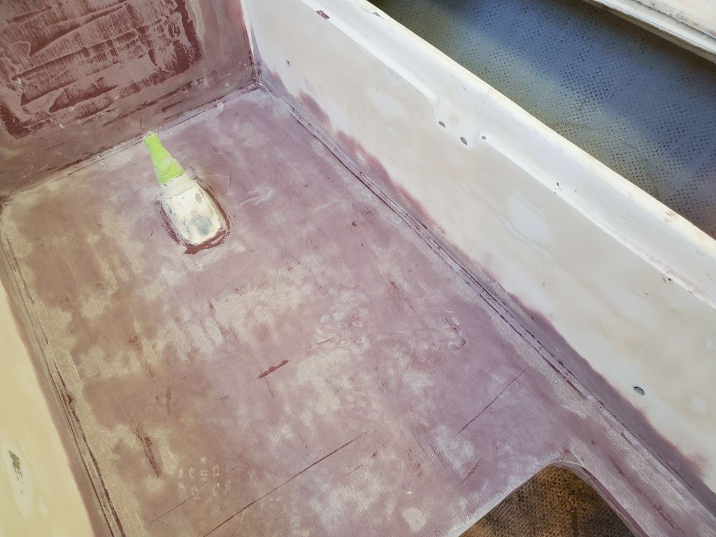
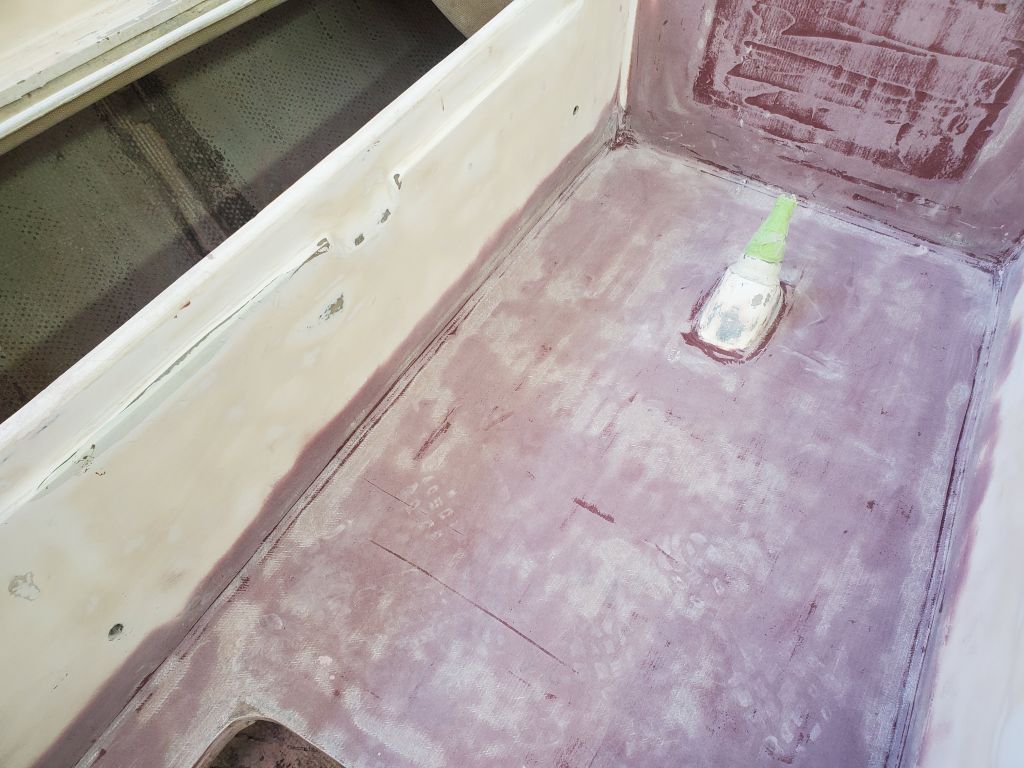
After thoroughly cleaning up, the cockpit was ready for a second round of fairing compound, this time mainly concentrated on the two larger structural patches (icebox hatch and aft lazarette), and the corners where the cockpit sole met the cockpit well sides.
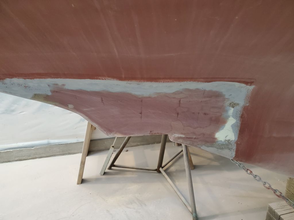
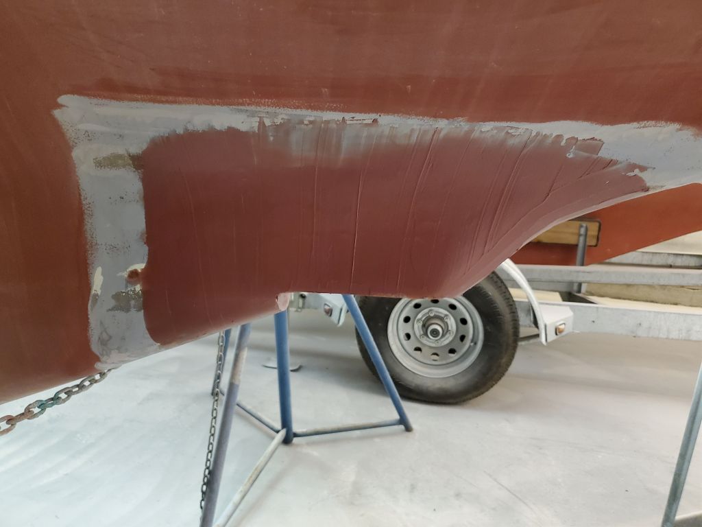
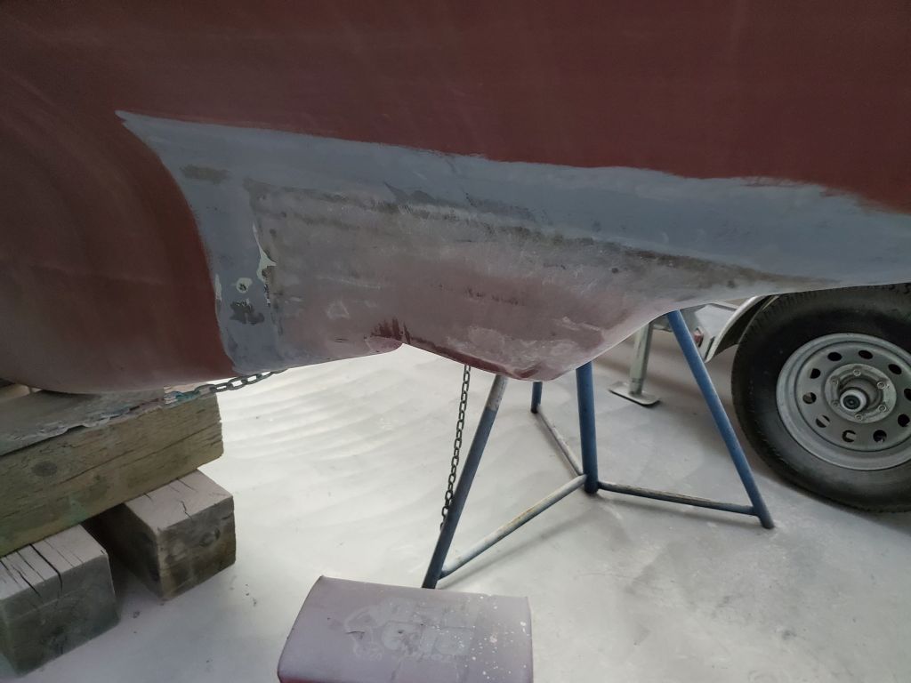
After a light sanding, the transducer housing was nearly complete–just a few pesky tool marks remaining, but the overall shape and profile was where I wanted it.
Later in the day, when I had some fairing compound leftover from another job, I filled these small voids.
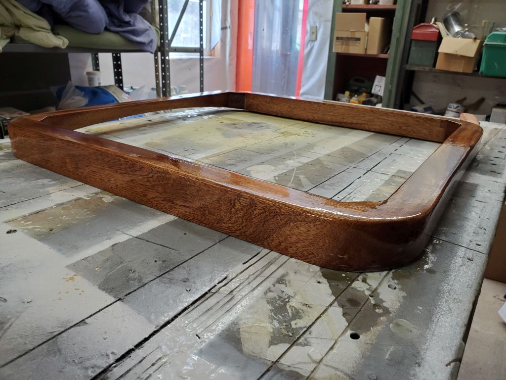
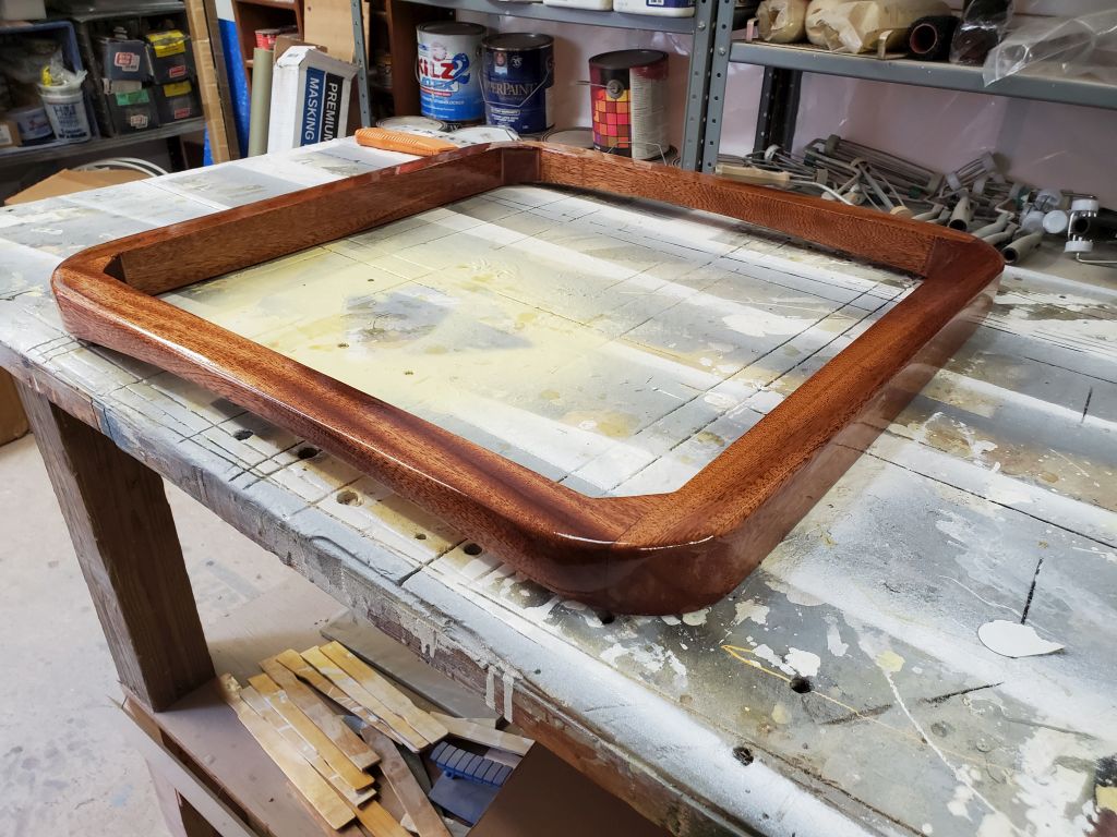
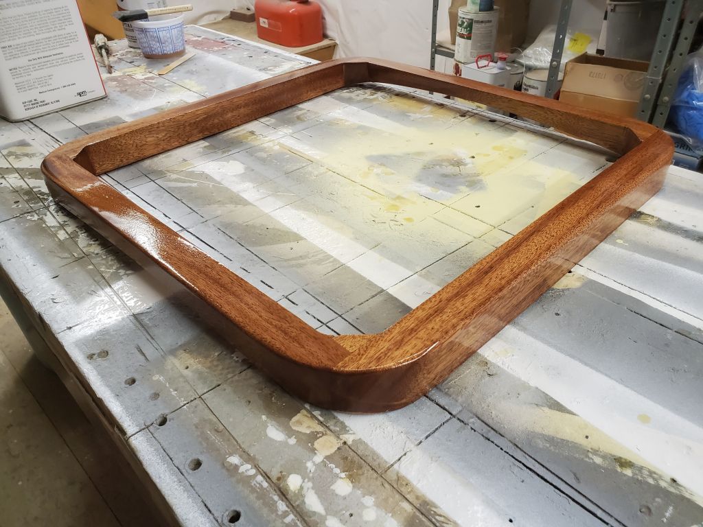
After giving the forward hatch frame a light sanding, I applied a second coat of varnish, a process I’d continue for the next several days.
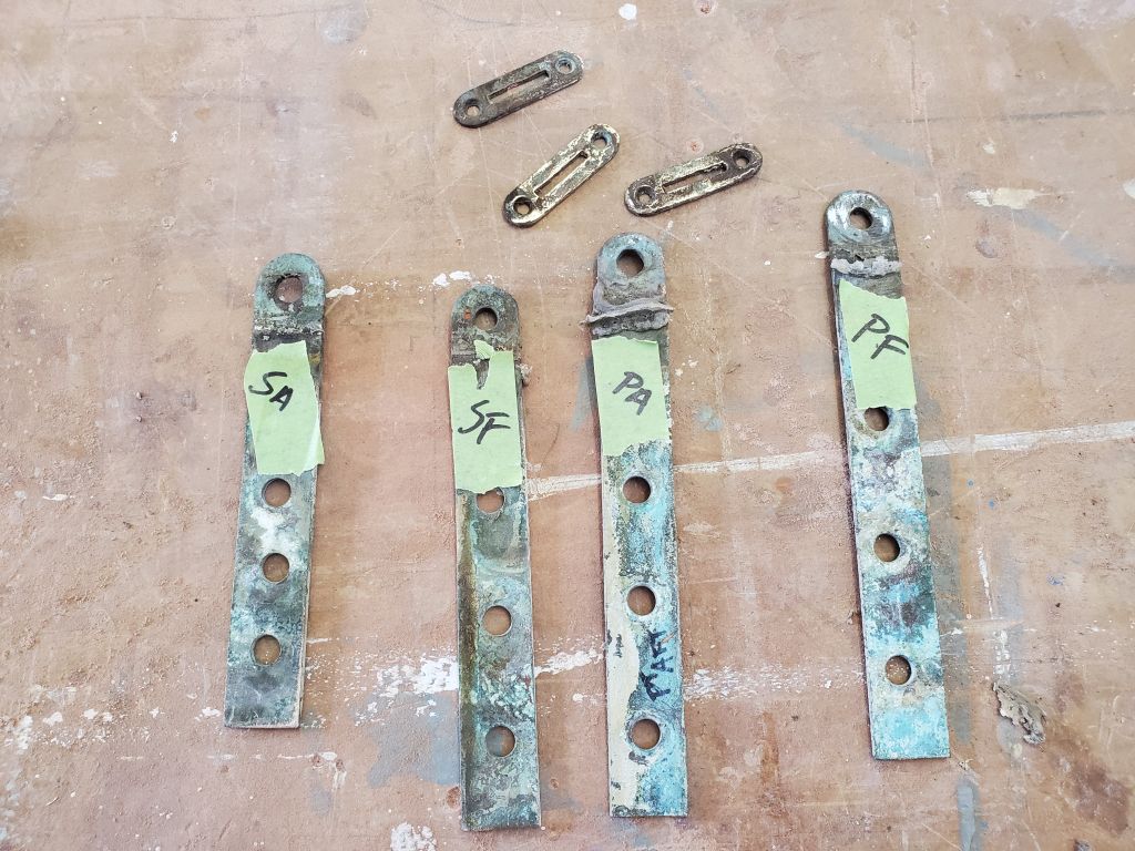
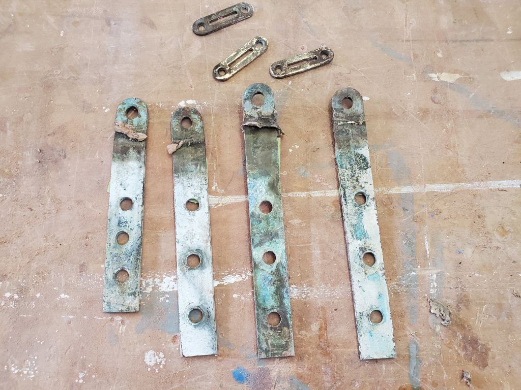
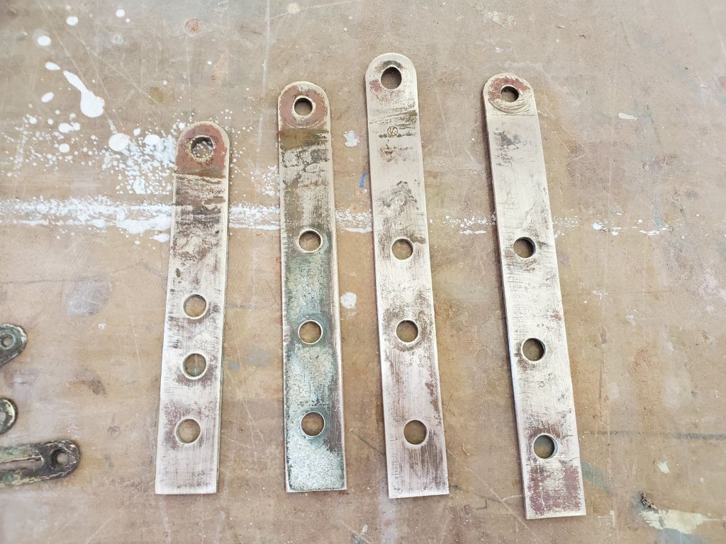
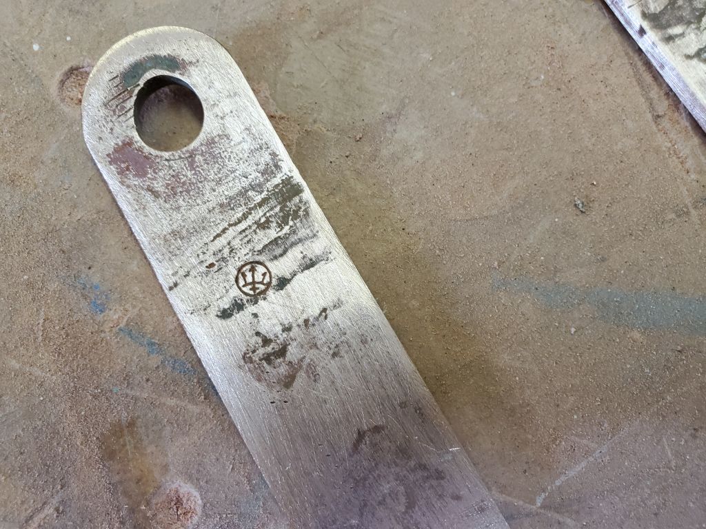
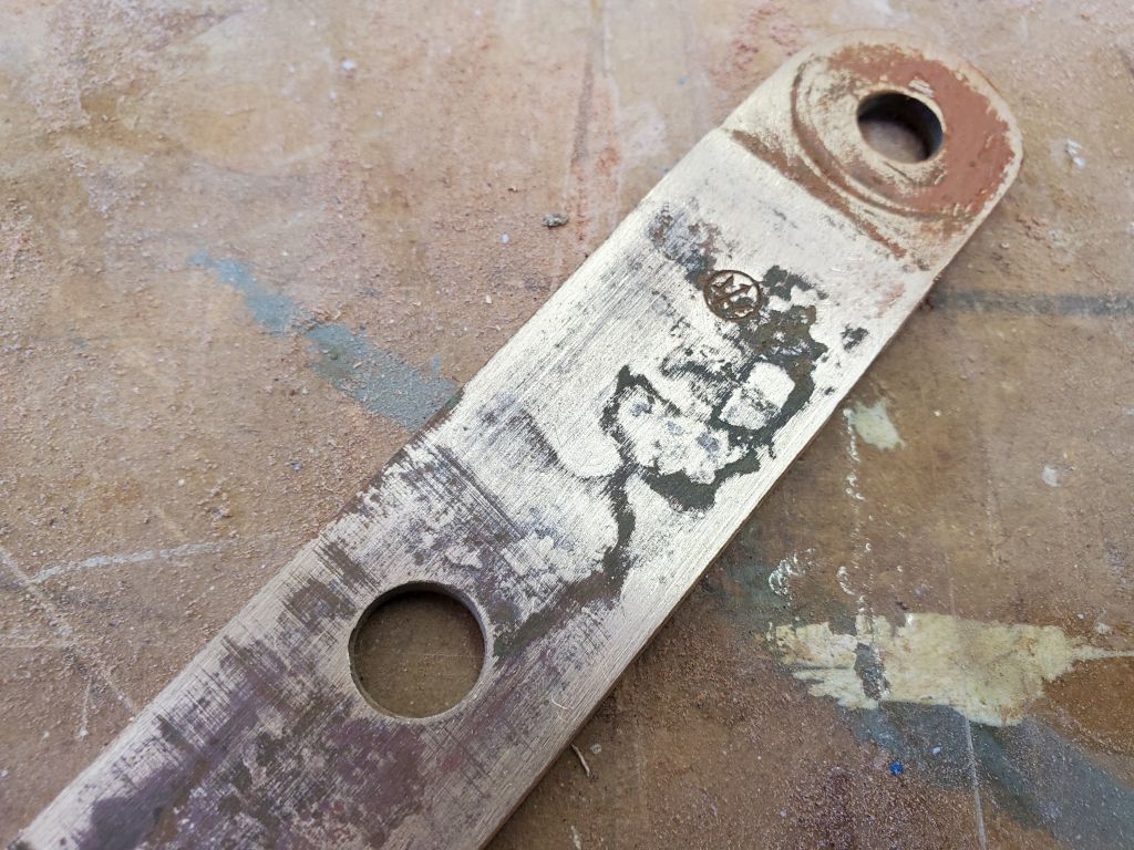
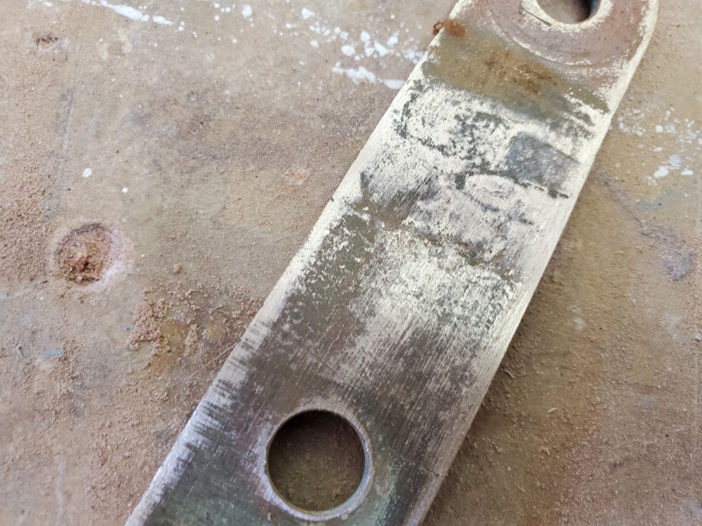
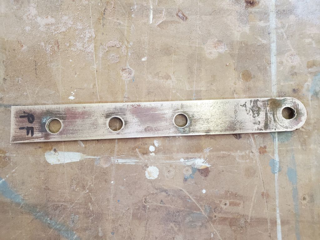
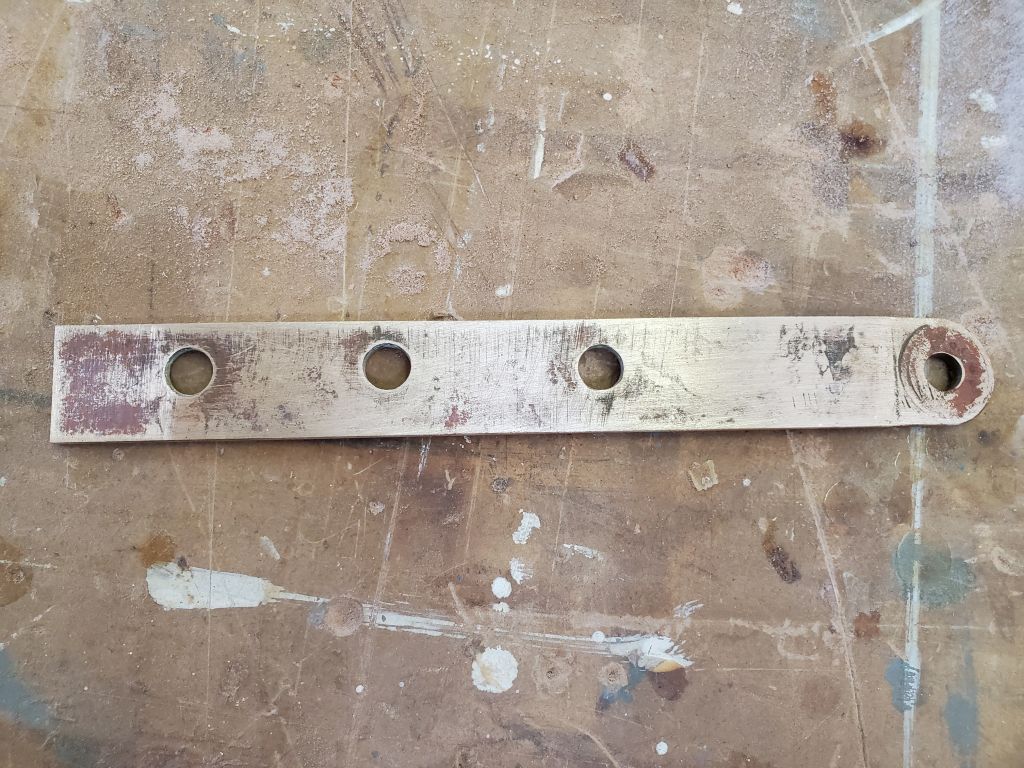
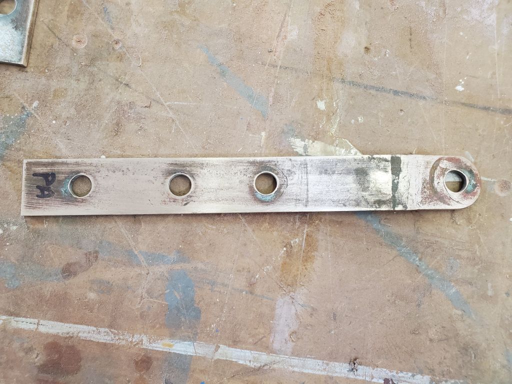
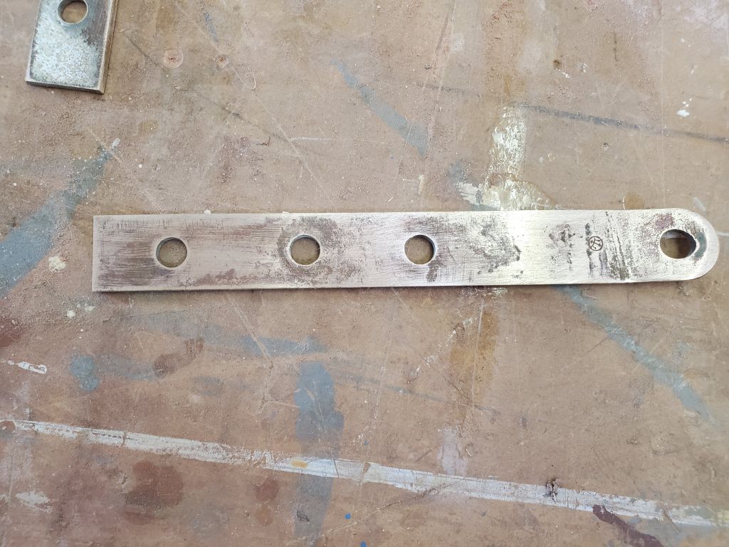
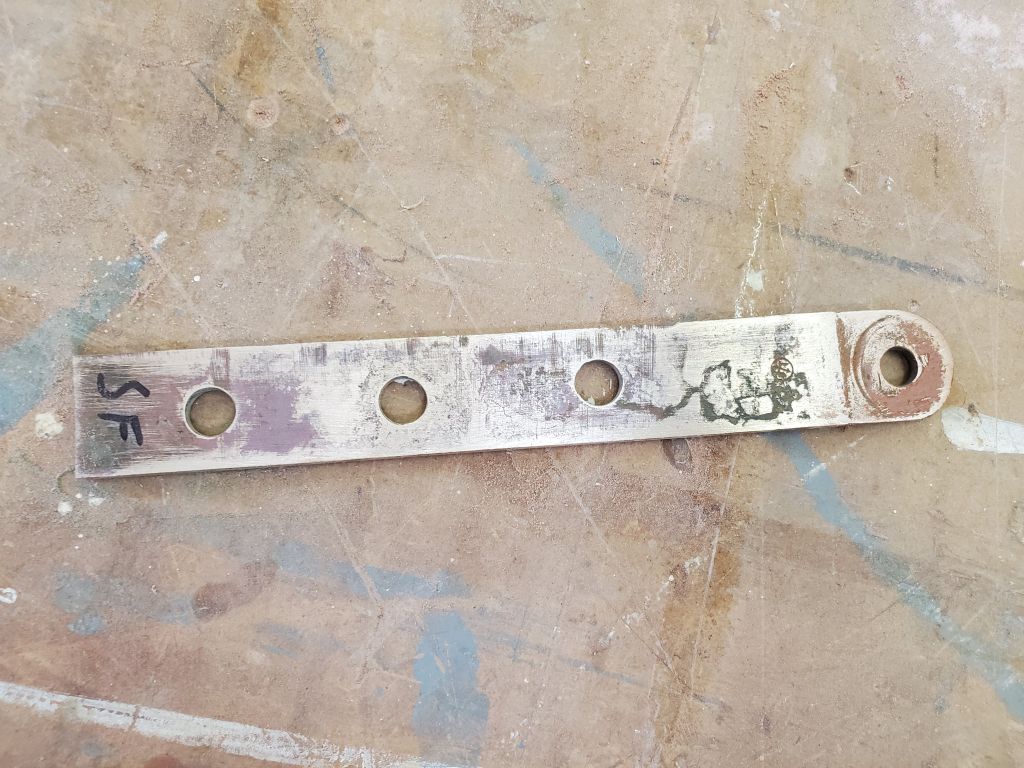
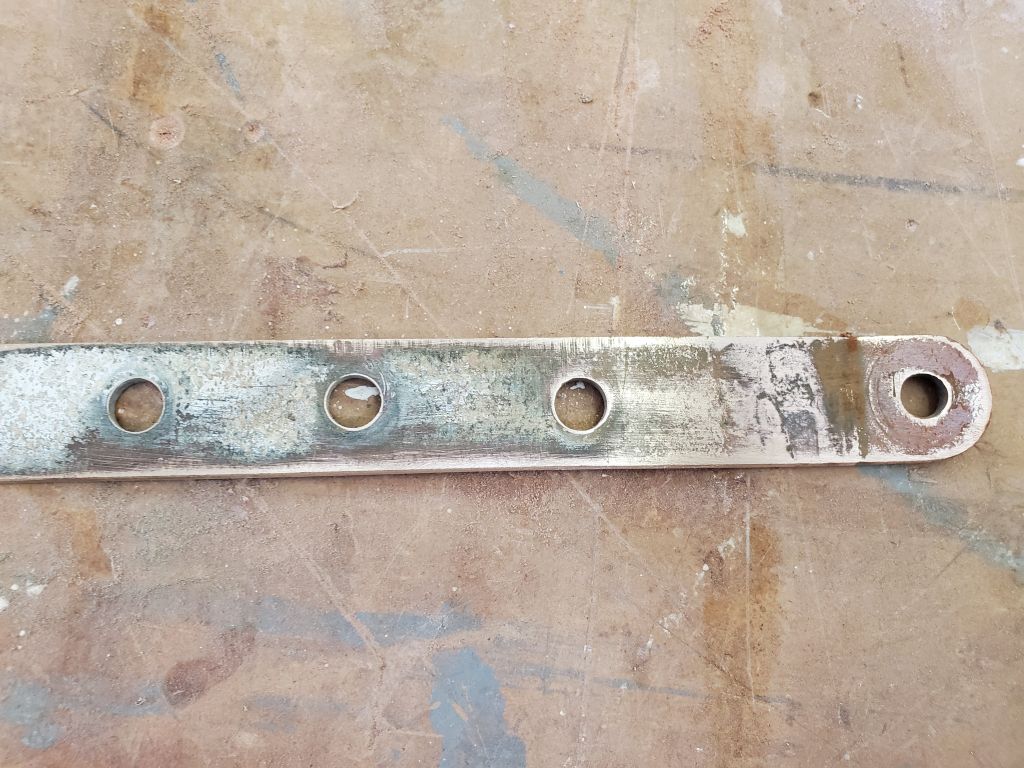
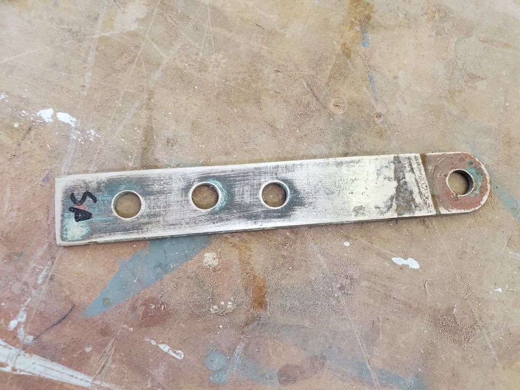
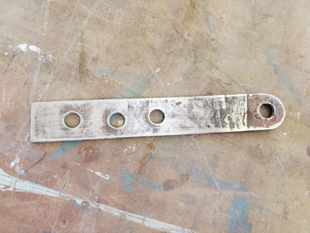
I quickly cleaned up the verdigris-coated bronze chainplates (original equipment, complete with Merriman logo) so I could better judge the metal’s condition. I didn’t bother cleaning the chainplates completely, as my goal was just to get an inspection efficiently. Getting past the idea that these chainplates seemed impossibly puny by today’s standards, the fact was they had (and still were on some sisterships) worked fine for 60 years, the bronze didn’t appear in terrible condition, but there was some discoloration suggestive of a metallic reaction, and various other signs of cumulative corrosion-related damage in the sort of topographic, dark-colored swirls seen hither and yon.
Total time billed on this job today: 5 hours
0600 Weather Observation: 0°, clear, 2″ or so of snow from yesterday. Forecast for the day: Sunny, 28°.
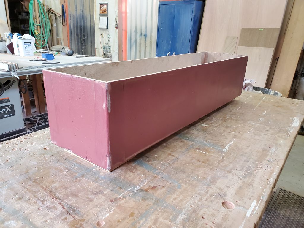
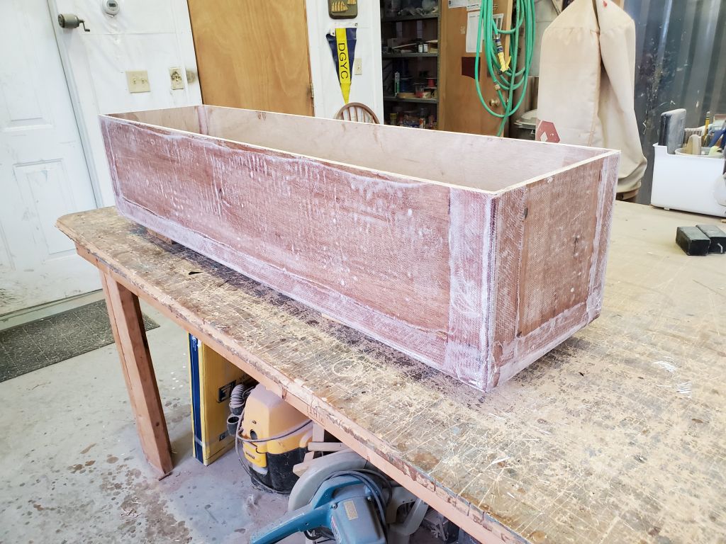
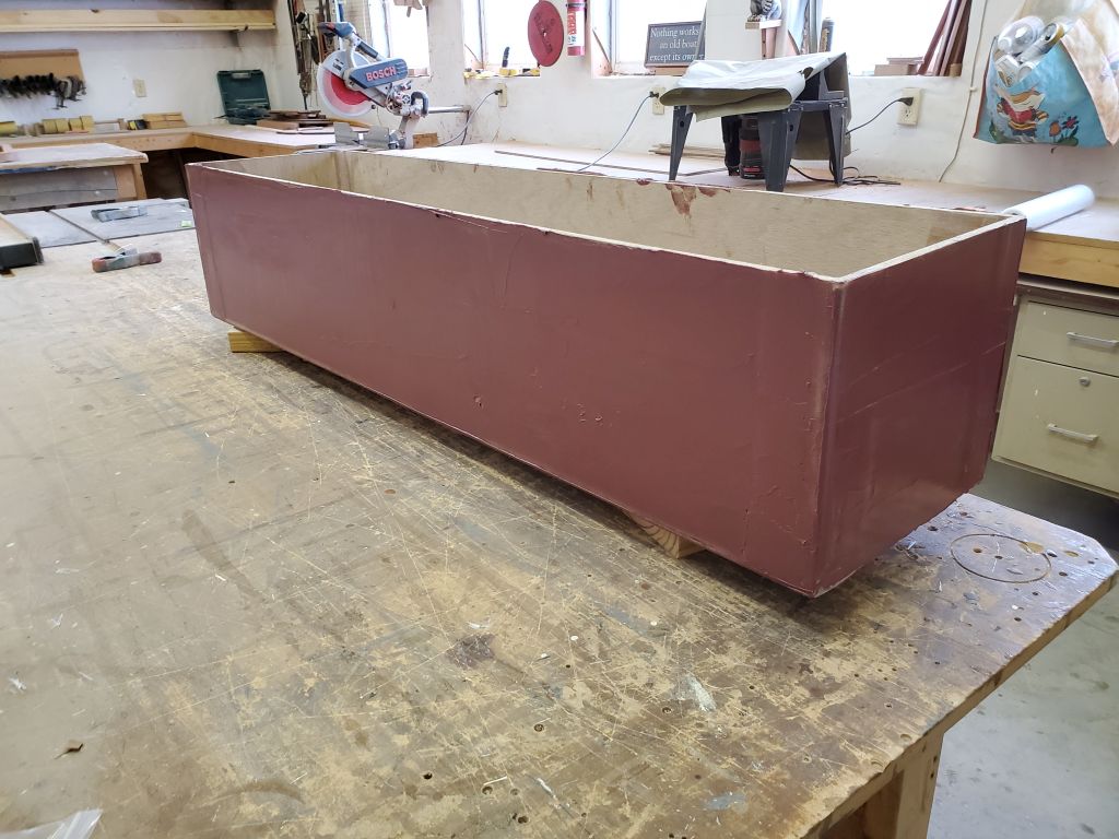
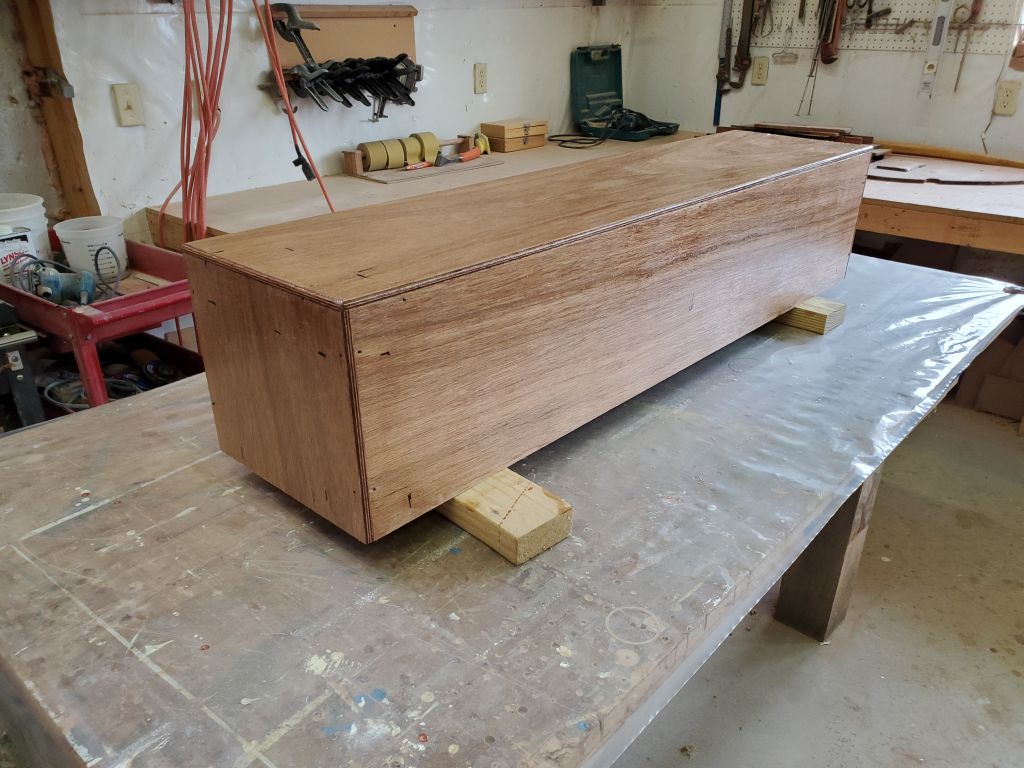
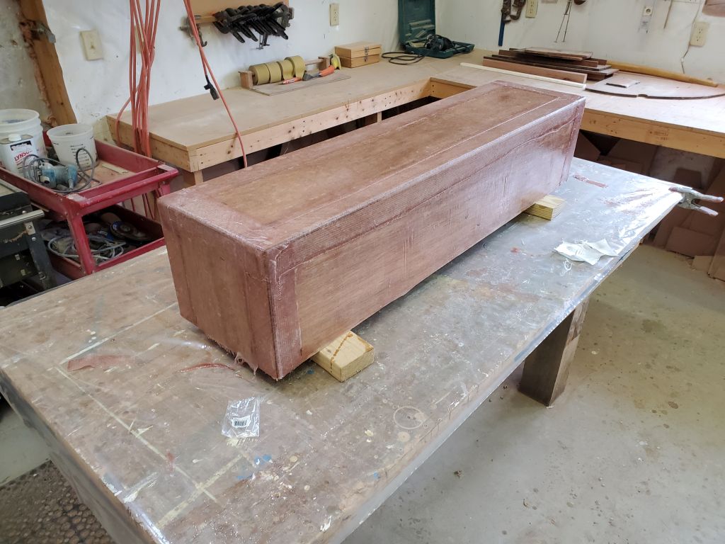
After a light sanding, I applied a round of epoxy fairing filler to the deck box, the first of a few required to prepare the exterior for the final paint finish.
Total time billed on this job today: .75 hours
0600 Weather Observation: 8°, cloudy. Forecast for the day: Cloudy, light snow in the afternoon, 21°.
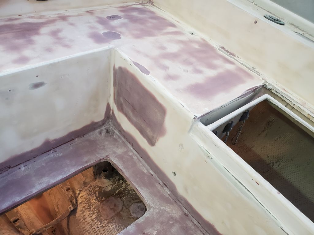
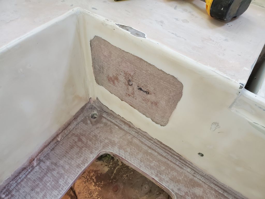
Continuing the cycle with these things, I began the day with a round of sanding to prepare the various fiberglass patches I’d completed last time: The icebox hatch; vertical lazarette hatch; gauge holes. As needed, I removed the backing tape and molds from these repairs and prepared the back sides for additional work where necessary.
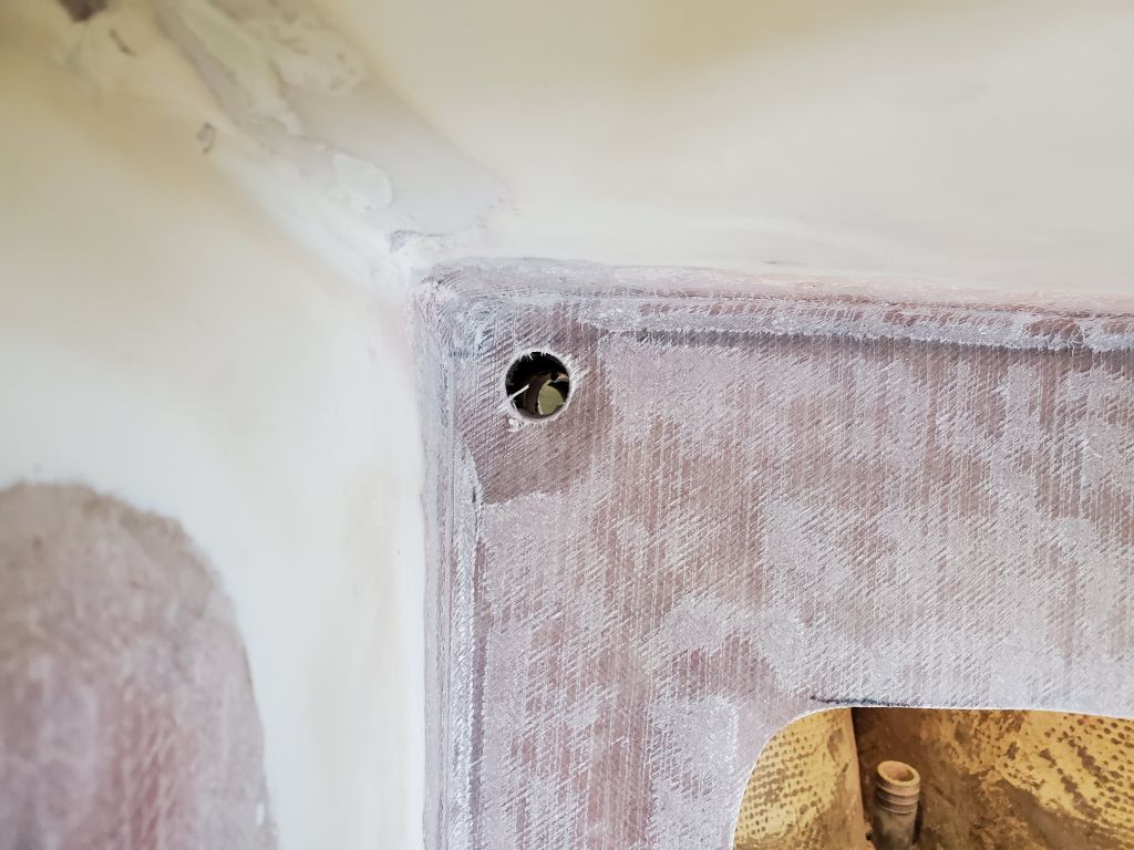
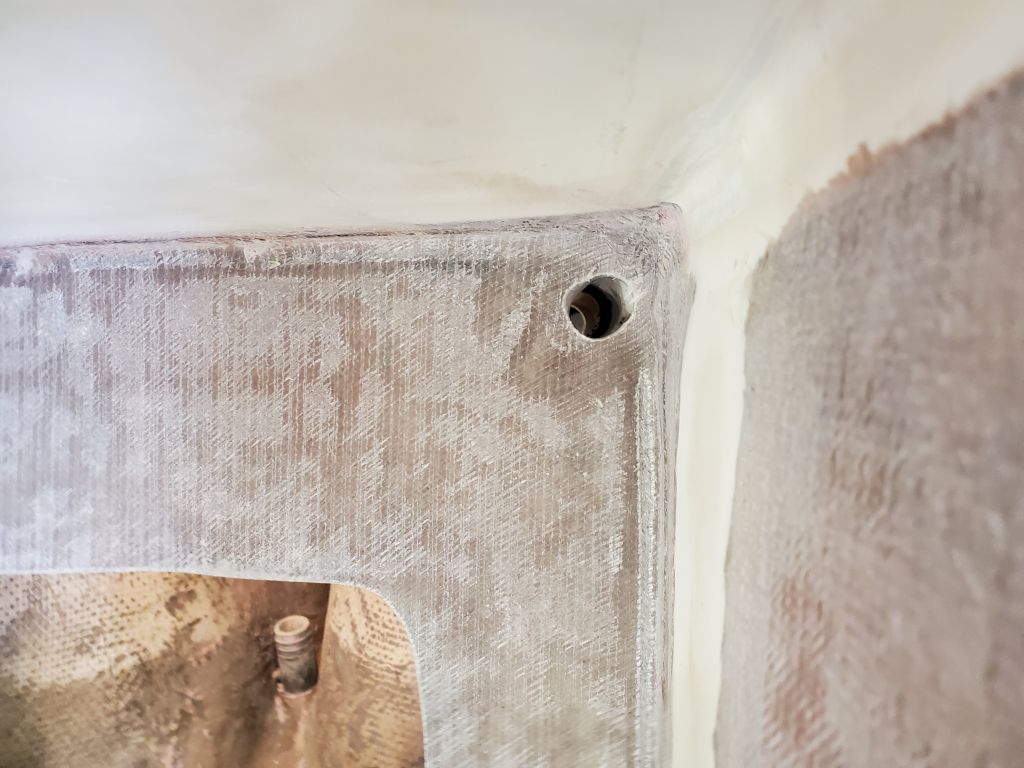
With a 1″ hole saw, I reopened the cockpit scuppers so I could continue work creating and cleaning up the top edges for finished appearance.
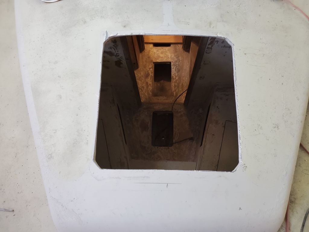
With a jigsaw, I slightly opened up the opening for the new cockpit sole hatch, as the solid fiberglass I’d installed around its perimeter overhung a bit on the forward side. With 1/8″ or so of trimming, the hatch fit properly once more. Meanwhile, I cut the opening for the forward hatch to the final size, following the lines I’d traced from the wooden hatch frame.
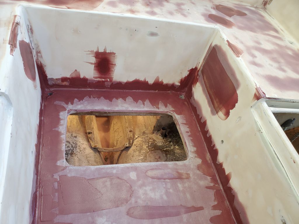
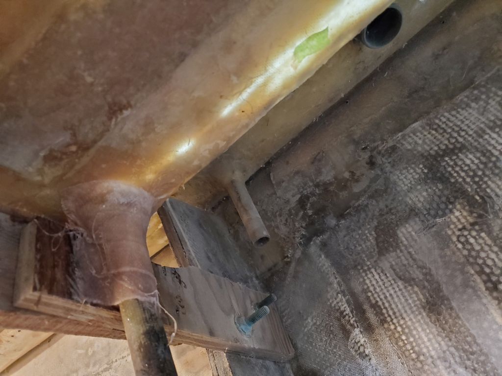
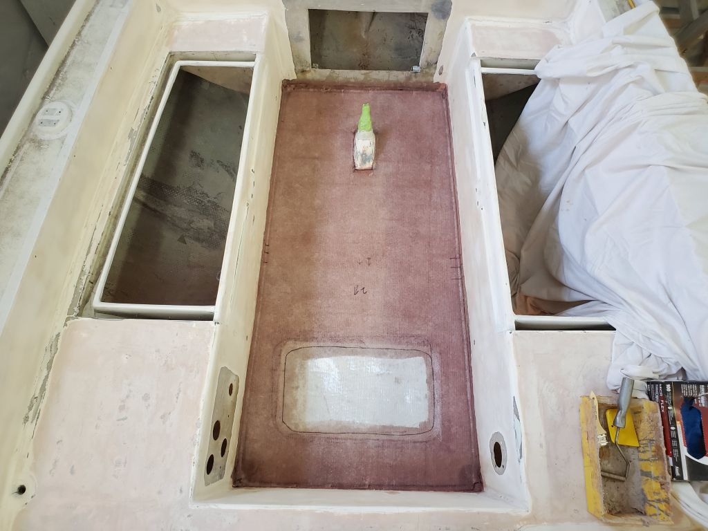
After final preparations, I added layers of fiberglass to the back sides of the icebox hatch repair, the engine gauge area, and the blower hole. I installed small fiberglass patches over the insides of the two old through hulls in the engine room as well.
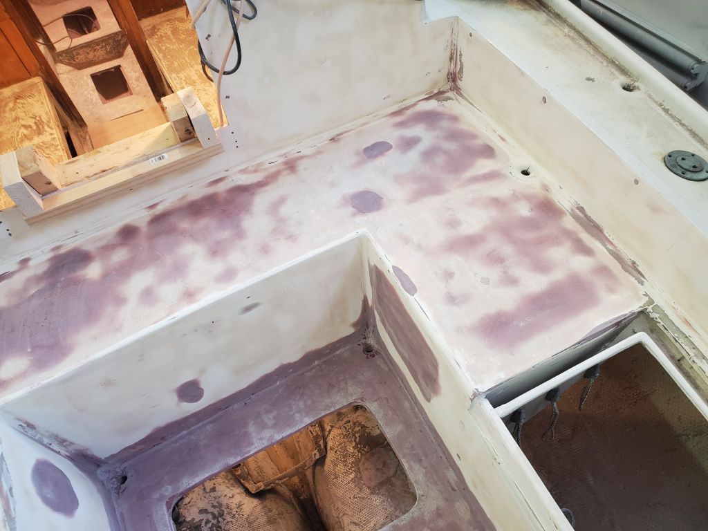
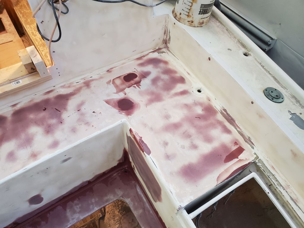
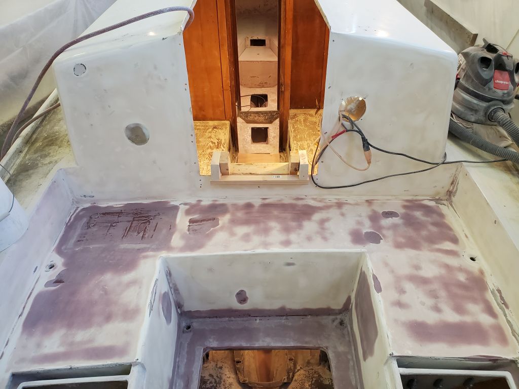
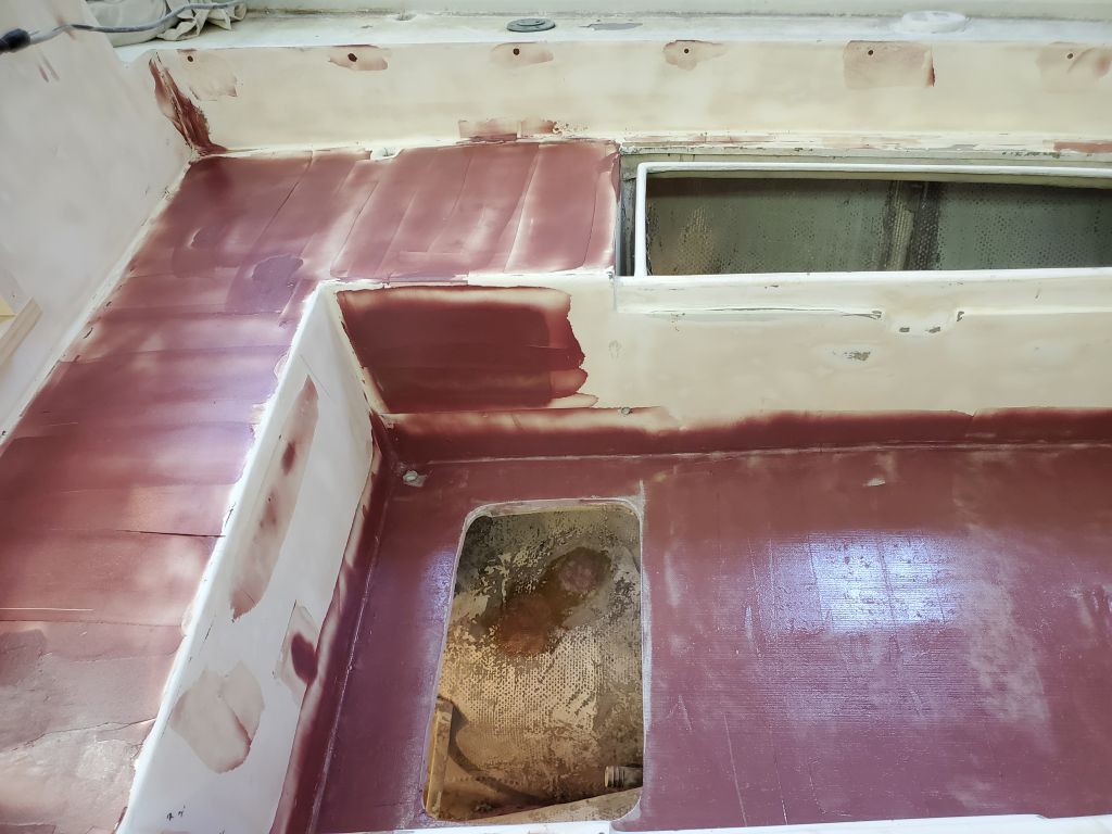
In the cockpit, I applied the first layer of fairing compound to the repairs, as well as a skim coat on the cockpit seating areas and new cockpit sole, plus filling the various screw holes and other areas requiring minor repair and filling.
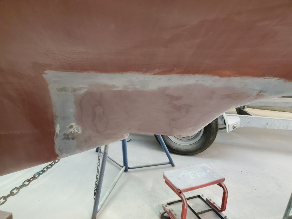
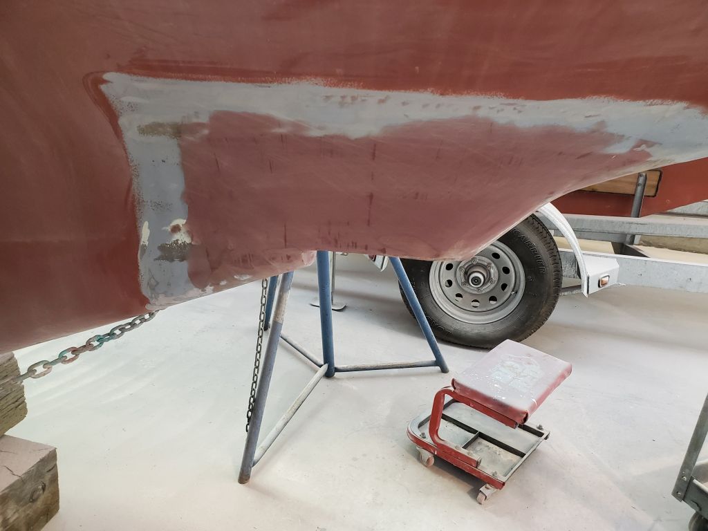
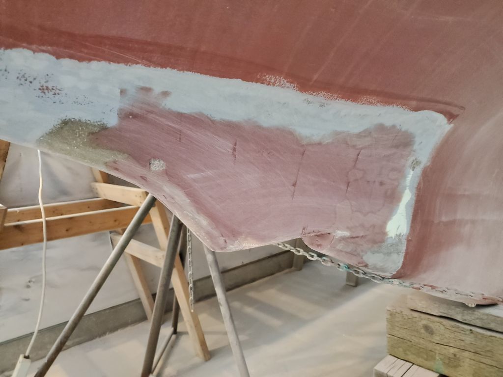
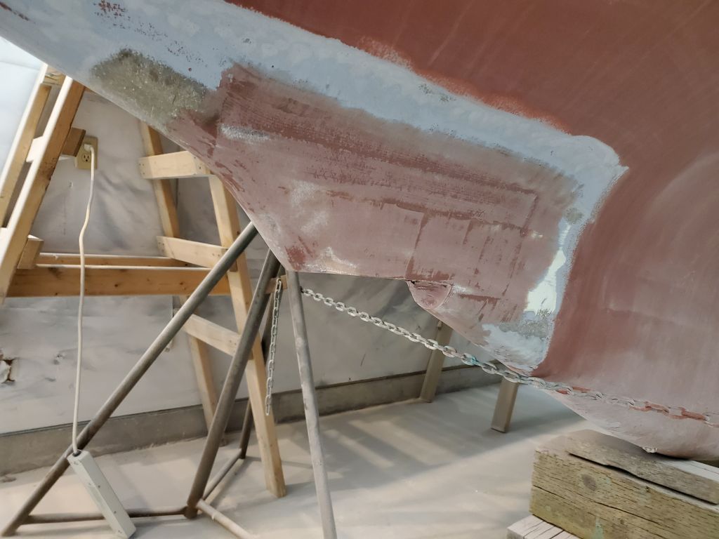
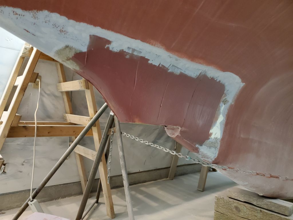
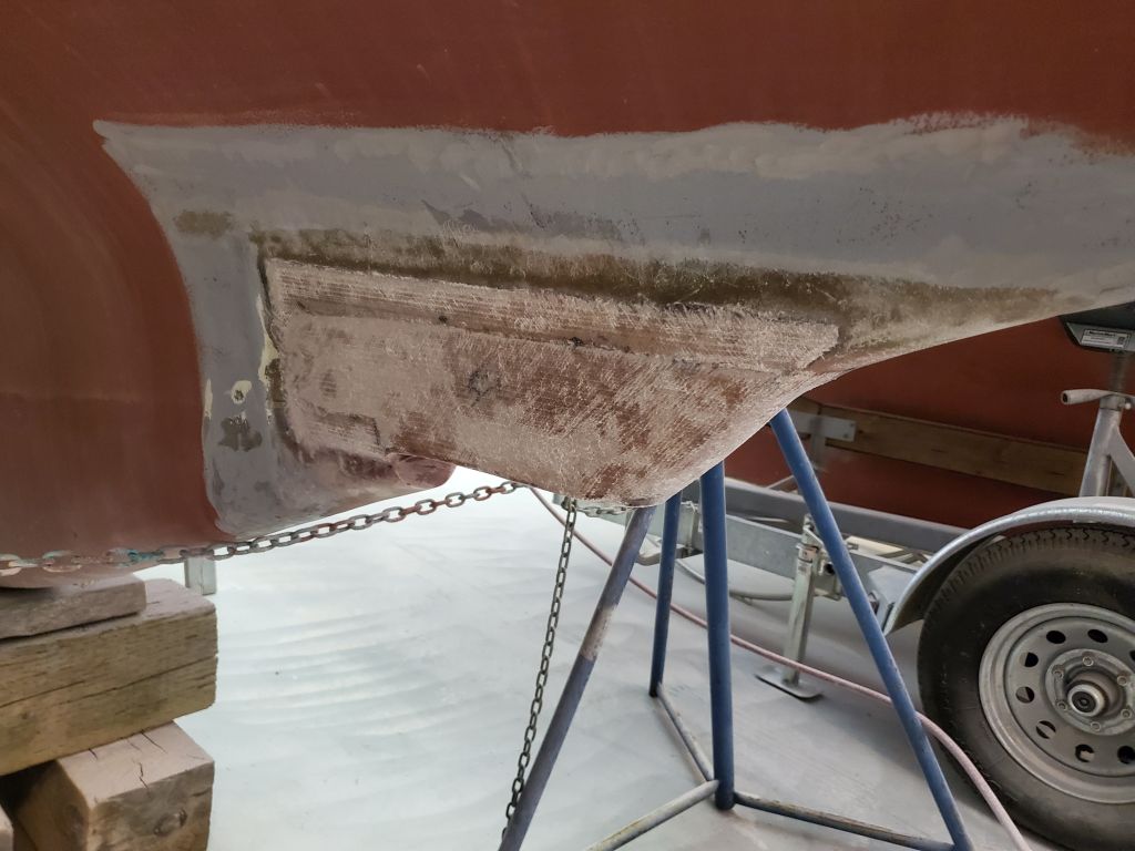
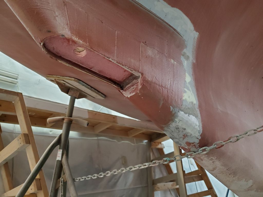
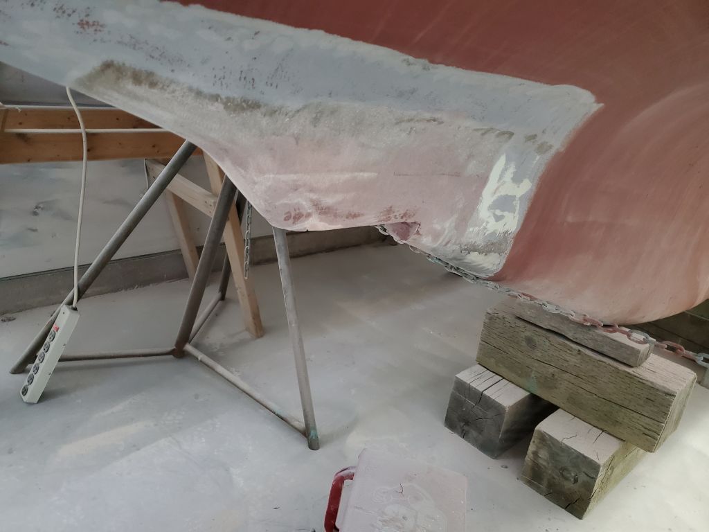
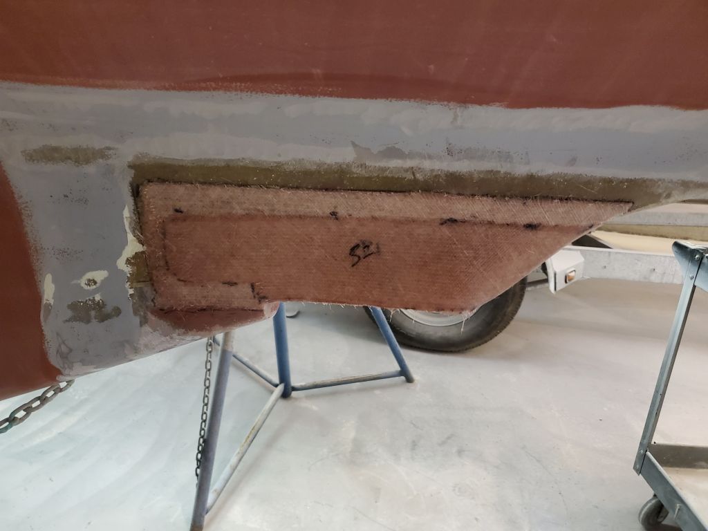
On the hull, I lightly sanded the first round of fairing filler on the transducer housing, then applied a second coat to further fine-tune the shape and fill the minor low spots.
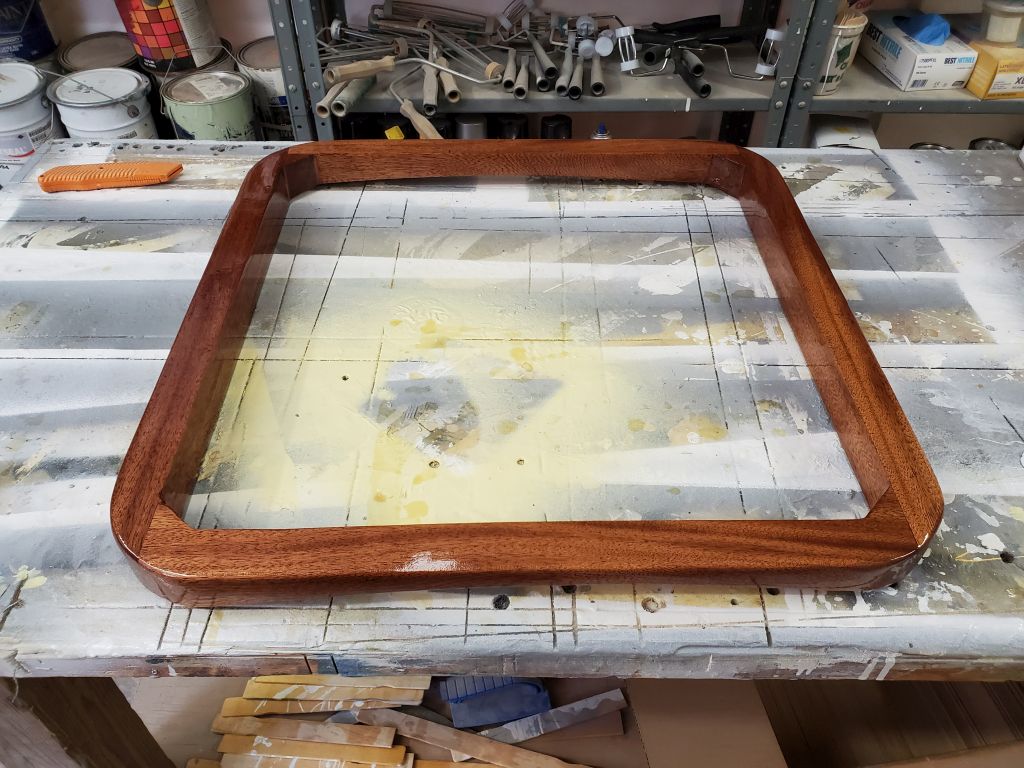
To round out the day, I finished up the milling work on the new forward hatch frame, rounding over the top outside corner for appearance and to hold varnish, and sanding the whole piece through 220 grit. Then, I applied a thin sealer coat of varnish to the piece, the first of several coats I’d apply before installing the frame permanently on deck.
Total time billed on this job today: 5.5 hours
0600 Weather Observation: 8°, cloudy. Forecast for the day: Cloudy, light snow in the afternoon, 21°.
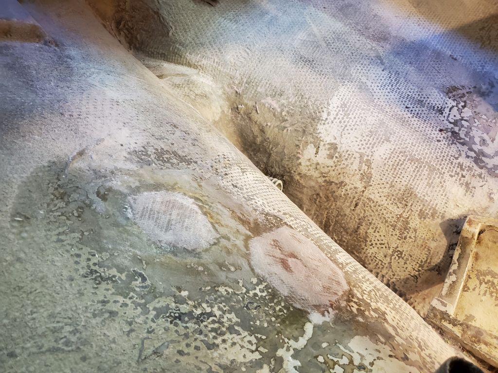
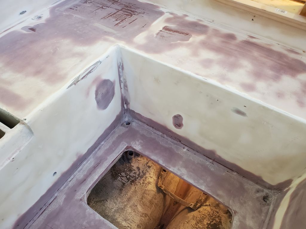
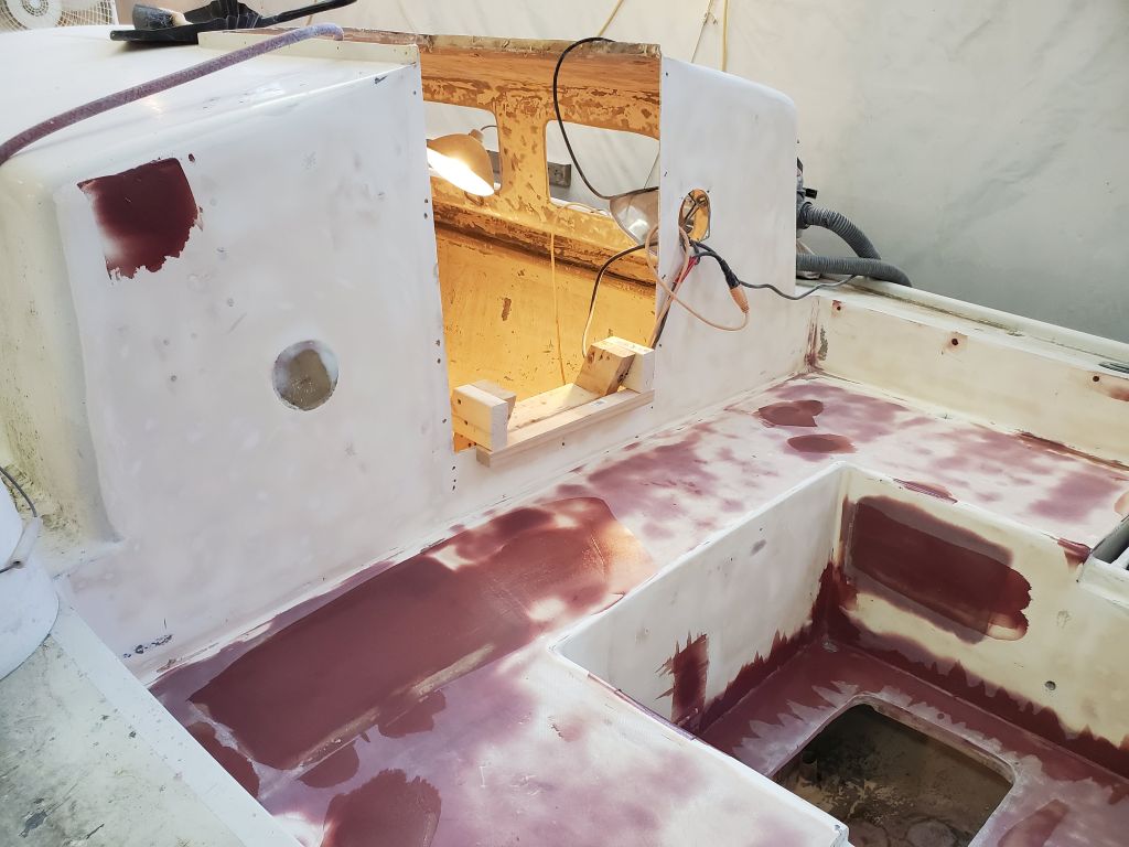
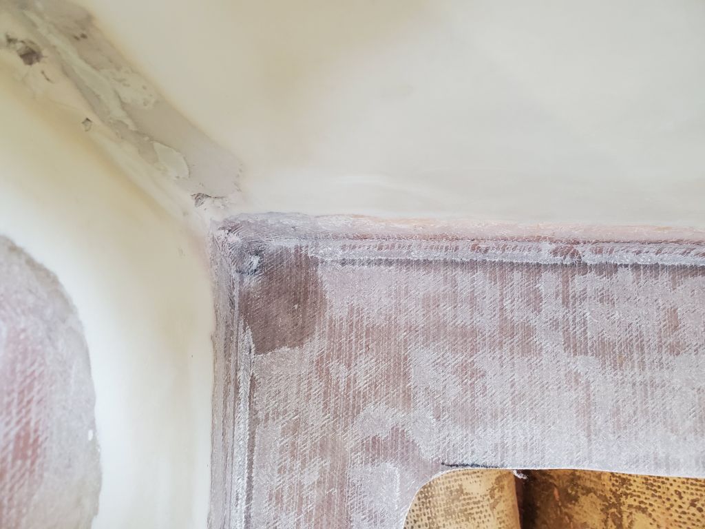
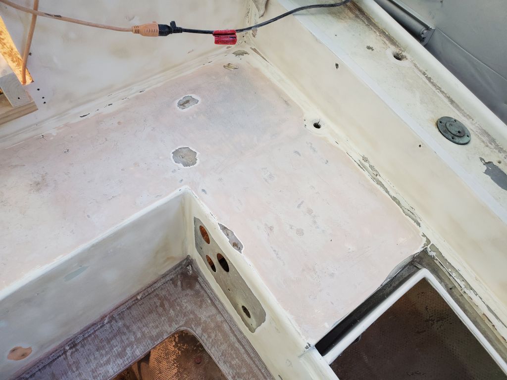
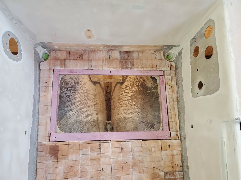
My next task in the cockpit was to lightly sand the new cockpit sole, and particularly the wrapped-up edges in the well, to prepare the new fiberglass for the next steps, and to smooth any rough edges as needed and with the adjacent surfaces. While I was in messy mode, I took care of some other final preparations in other parts of the cockpit, grinding out a few cracked or minorly-damaged areas in the seats and on the raised traveler platform aft, and also sanded the inside of the lazarette now that I had good access from the top. For the crack chasing, I had to be selective as to what I ground out, since if I’d chased all the cracks in the cockpit and seating areas, I’d be grinding and filling for weeks. I avoided the hairline cracks and focused on areas that might tend to show through the paint. In the coming days I’d fill these areas with epoxy in conjunction with related work in the cockpit.
With the sanding complete for now, I cleaned up the cockpit, adjacent lockers, and parts of the cabin fairly well so I could work in the area during the rest of the day.
The new cockpit sole was strong and stiff underfoot, a vast contrast from the original condition.
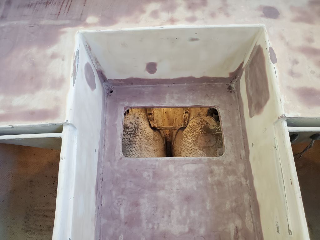
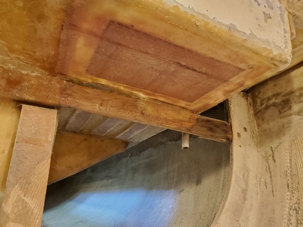
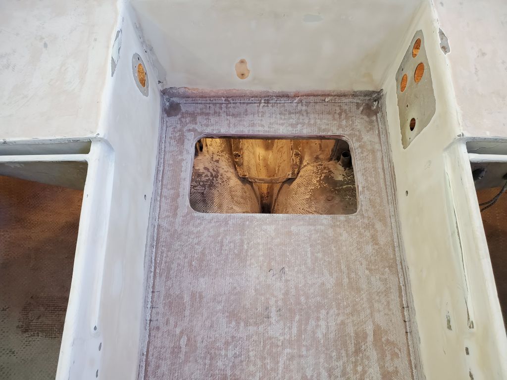
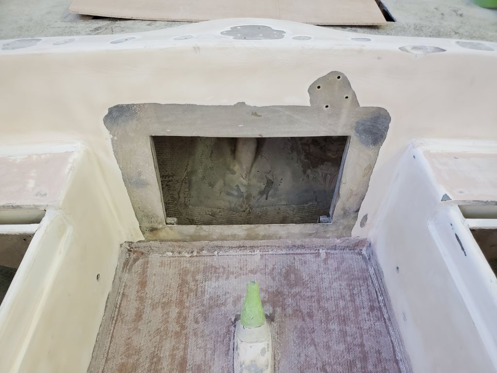
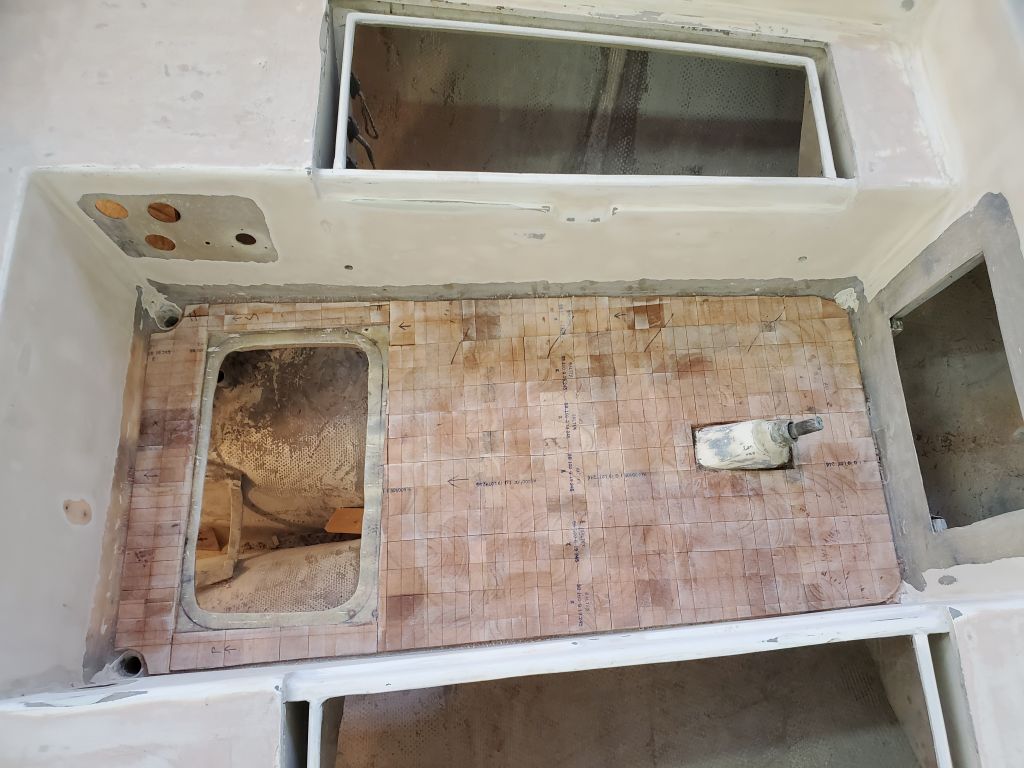
My plan for the day was to concentrate on the remaining cockpit repairs, including patching the old icebox hatch, the vertical opening to the lazarette, and the old engine gauge and blower holes.
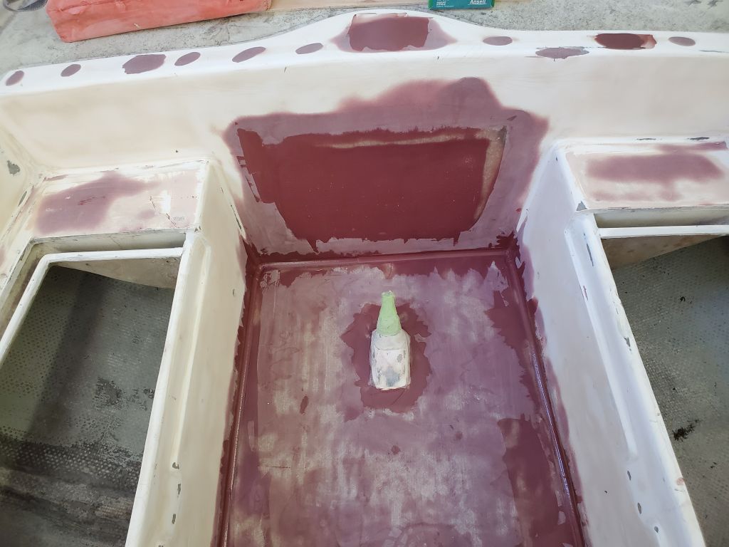
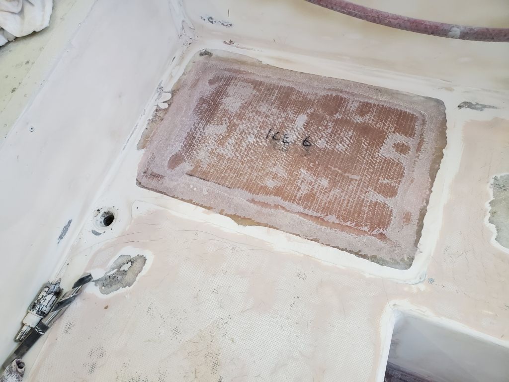
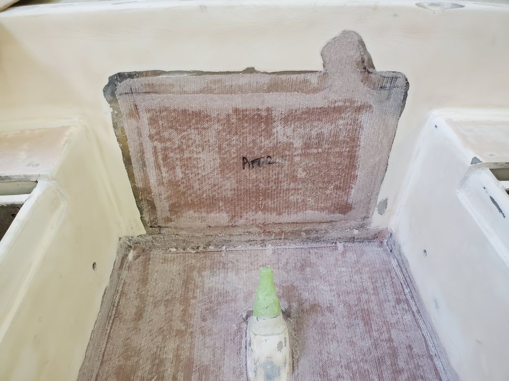
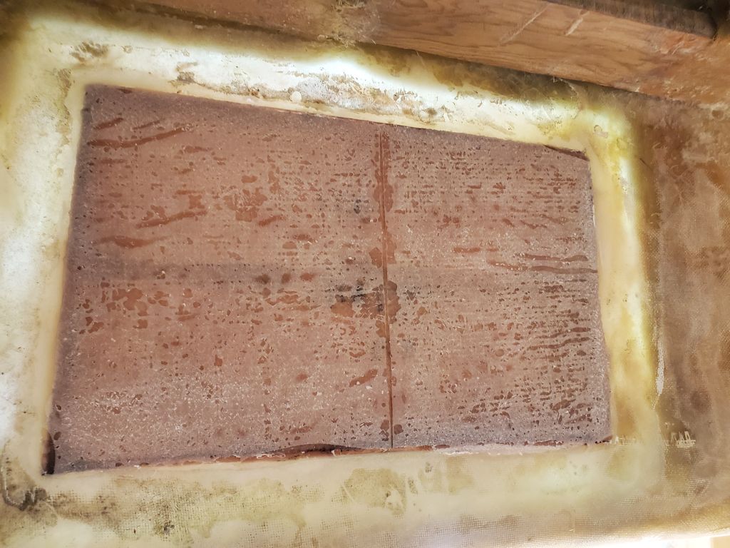
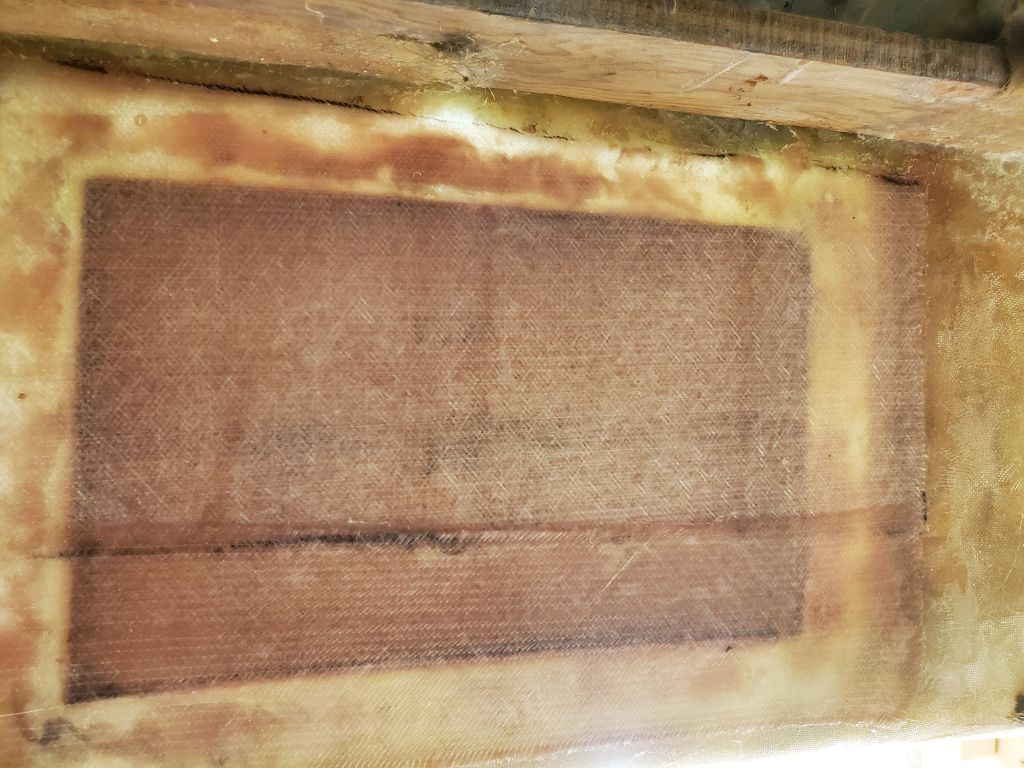
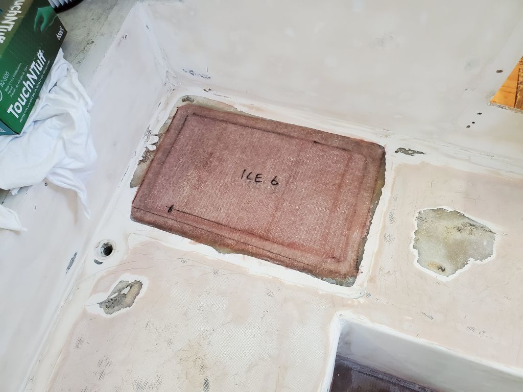
I spent most of the morning on final preparations for the various patching, starting with a simple mold for the icebox hatch, made from 1/4″ scrap plywood, plastic, some glued-on stiffeners, and various braces to hold it tightly from below. This would give me a place against which to fill in and laminate the replacement skin for the hatch opening. I cut fiberglass layers to fit within the hatch opening, and then larger ones to overlap the top onto the adjacent seating areas.
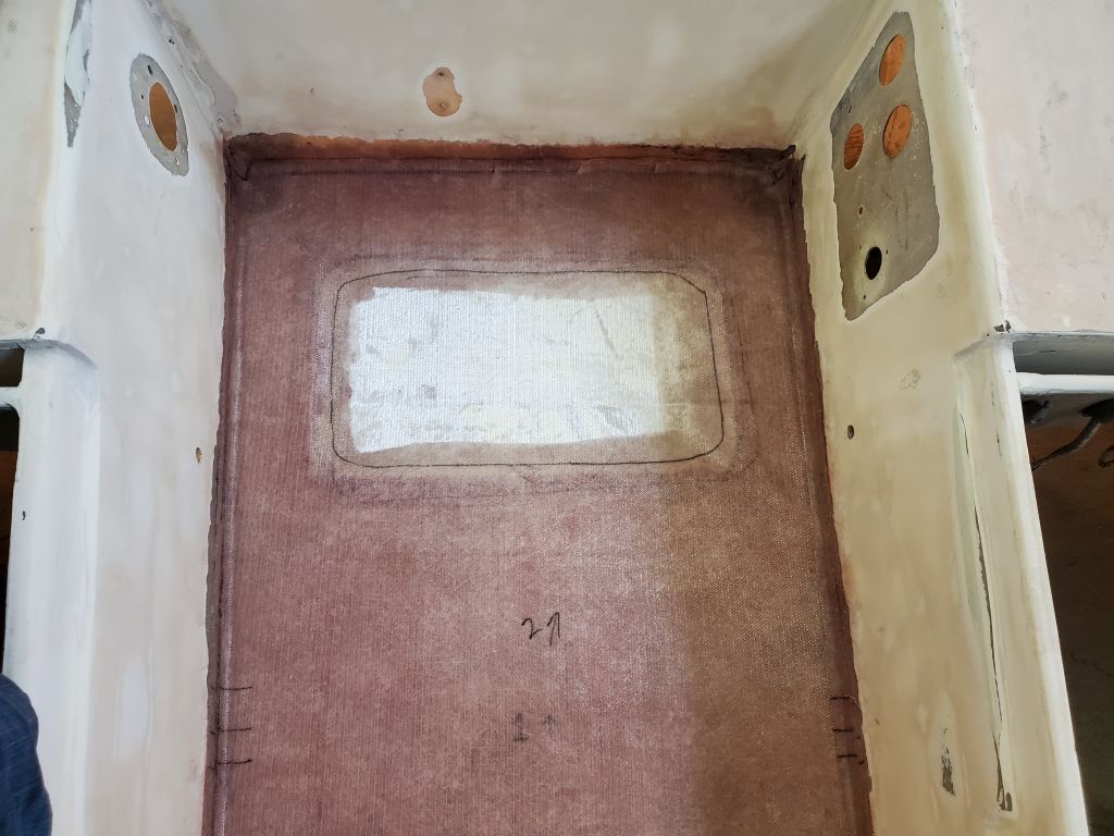
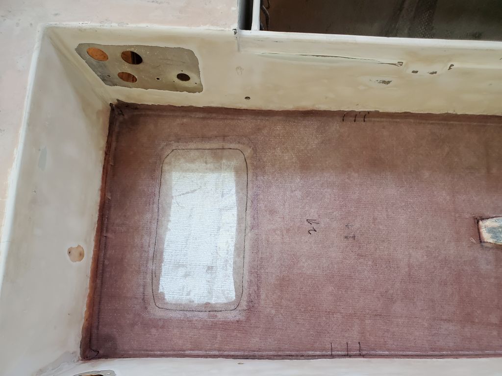
I filled in the icebox hatch opening with four layers of fiberglass, then overlapped them with two additional layers to tie it all into the cockpit seat.
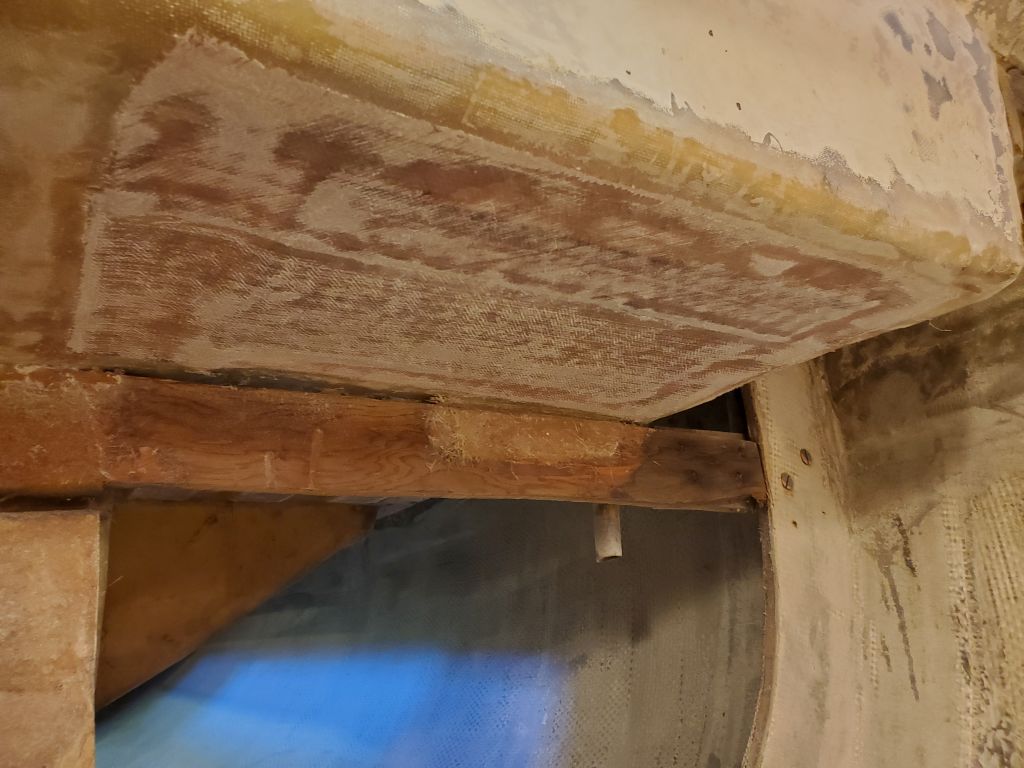
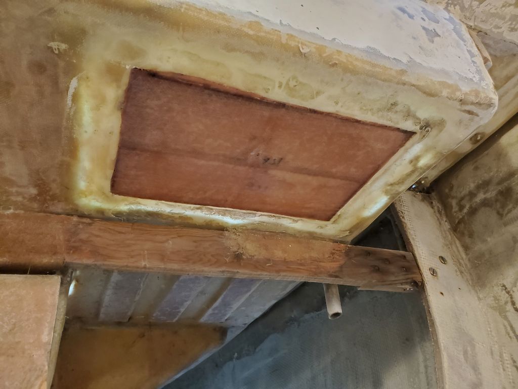
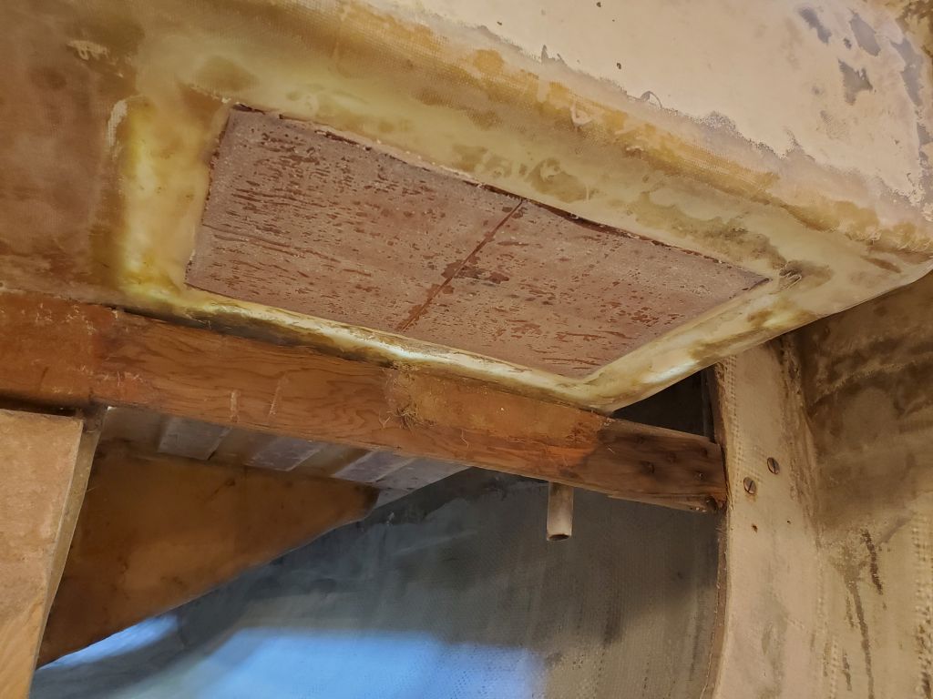
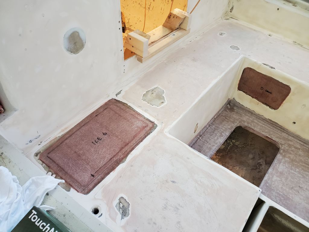
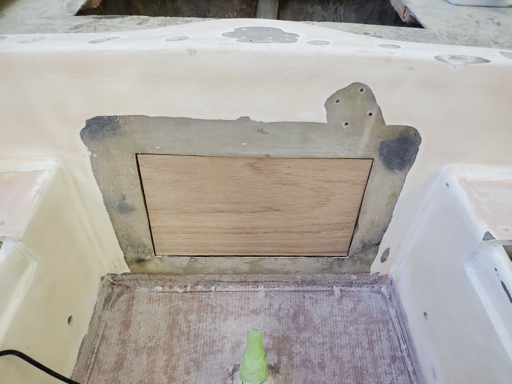
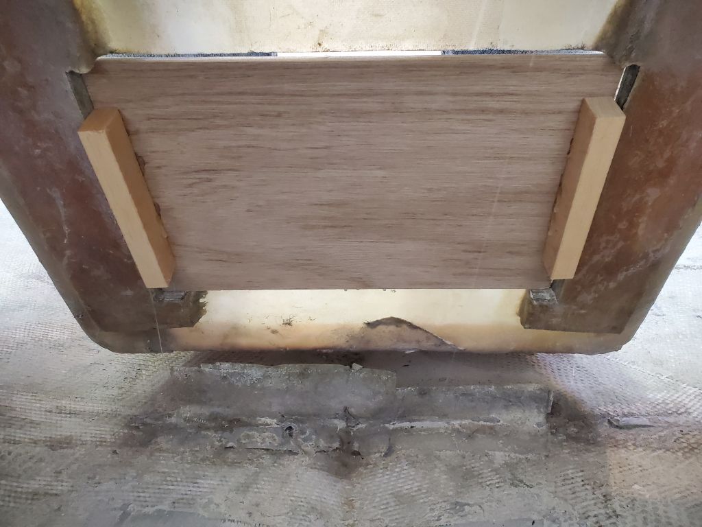
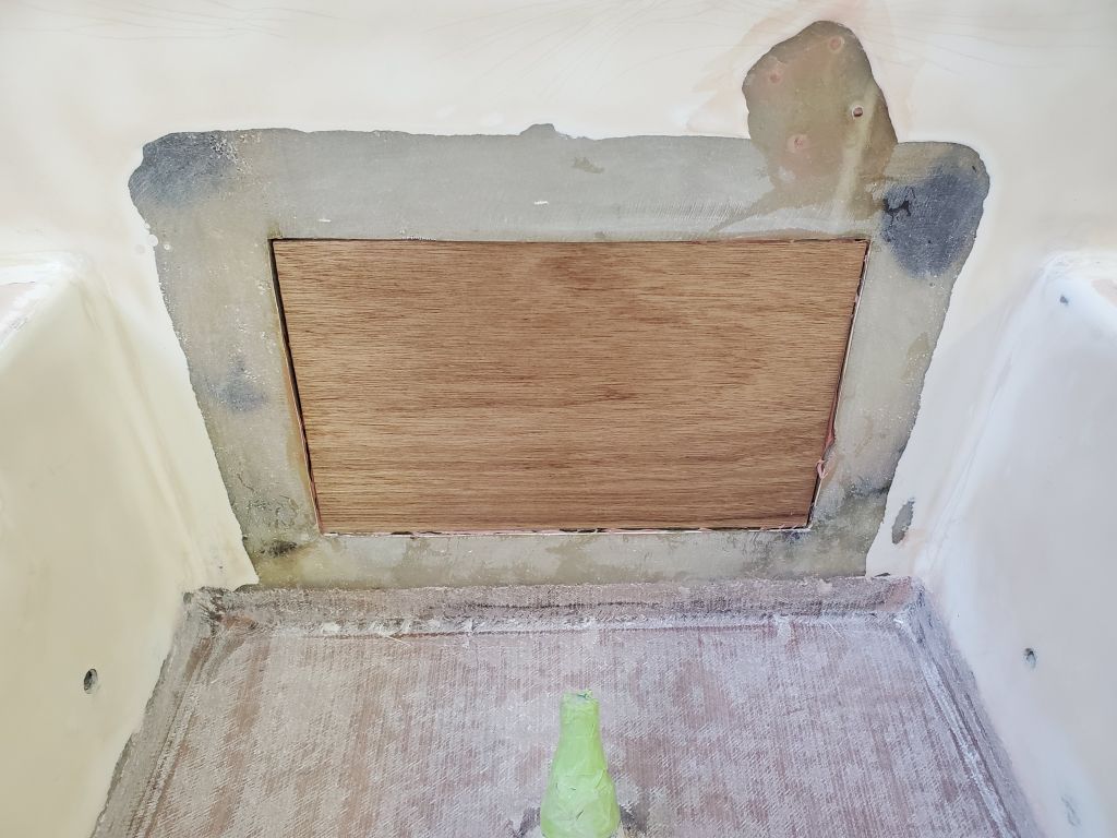
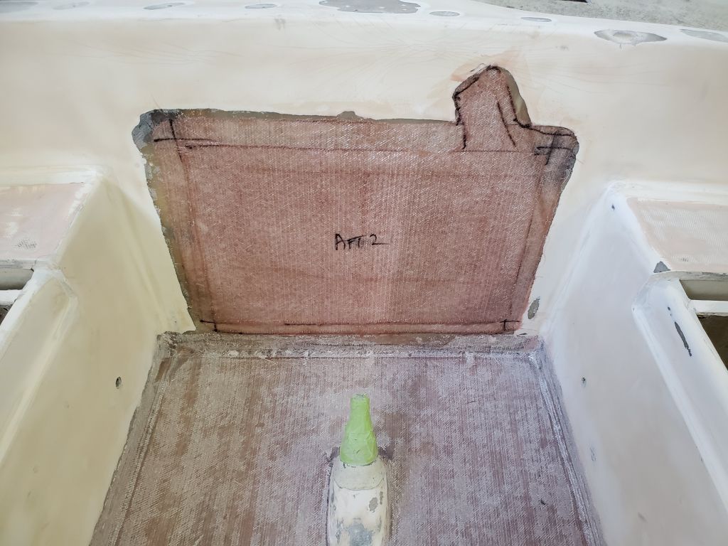
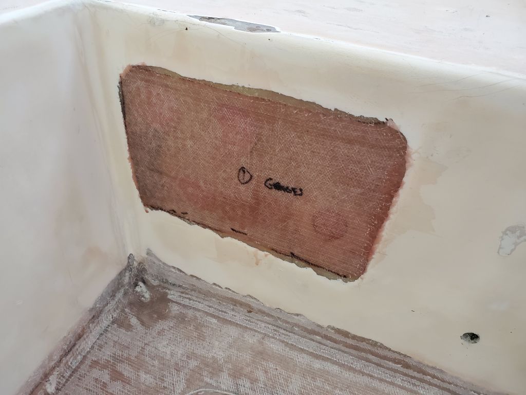
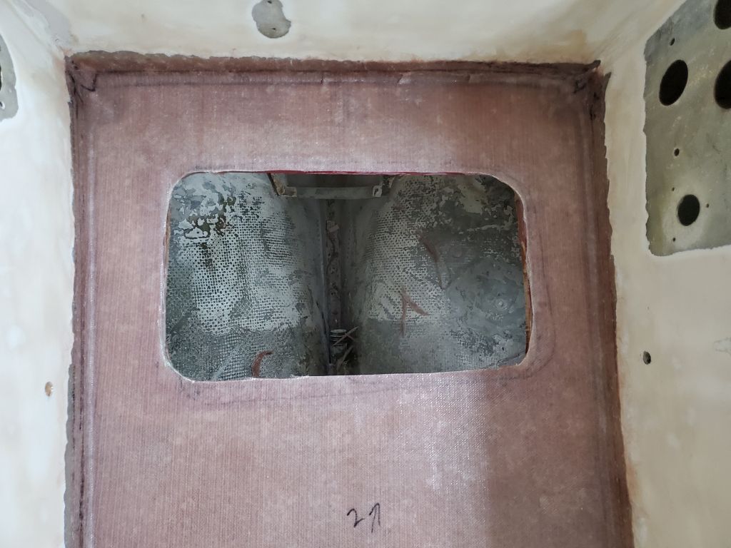
For the old opening into the lazarette, I cut a piece of 9mm marine plywood to fit inside the opening–chosen since there was a plywood banding surrounding parts of the old opening–and secured it in place with some temporary blocks hot-glued on the back side, holding the plywood roughly flush with the back side of the opening. I cut fiberglass to fit over the plywood, and larger layers to extend onto the nearby surfaces to tie the whole thing together. I wet out the plywood with epoxy, then installed three layers of fiberglass over top.
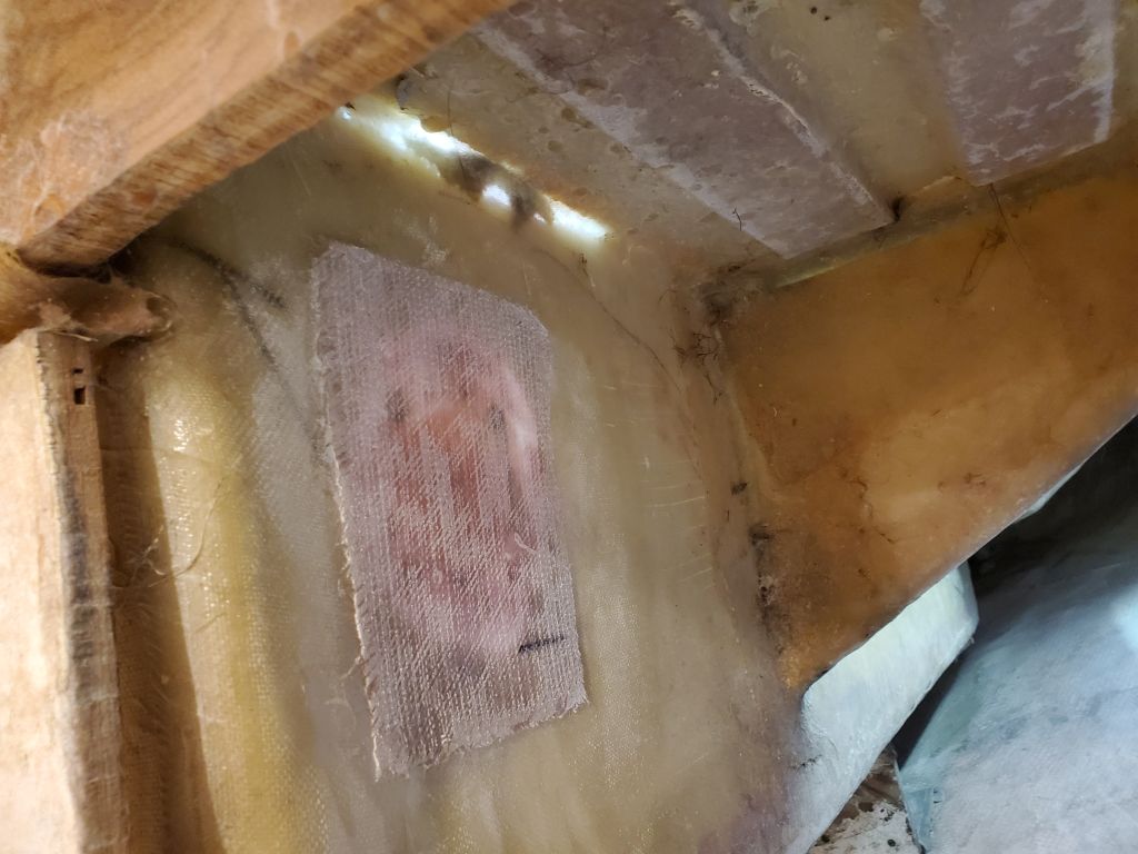
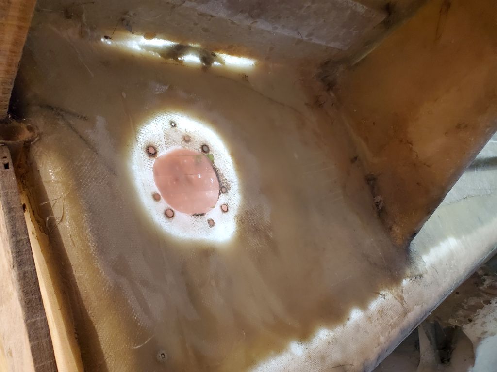
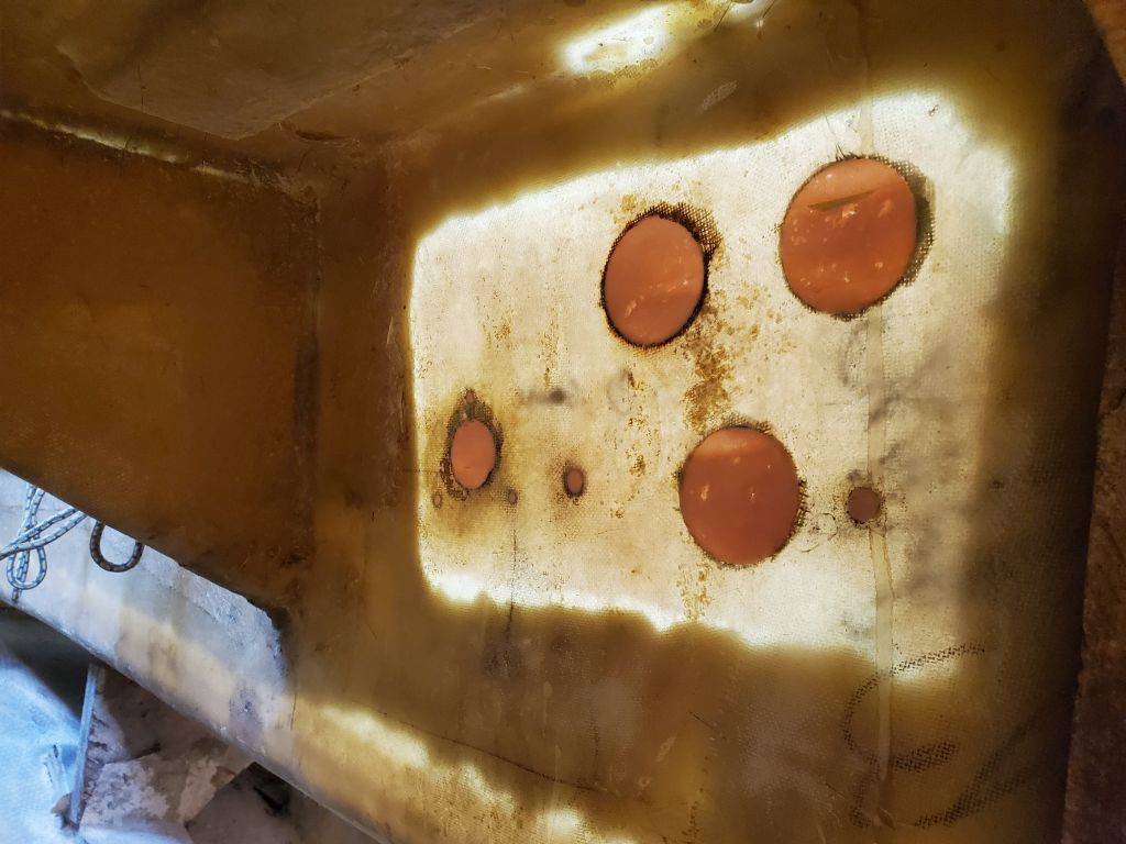
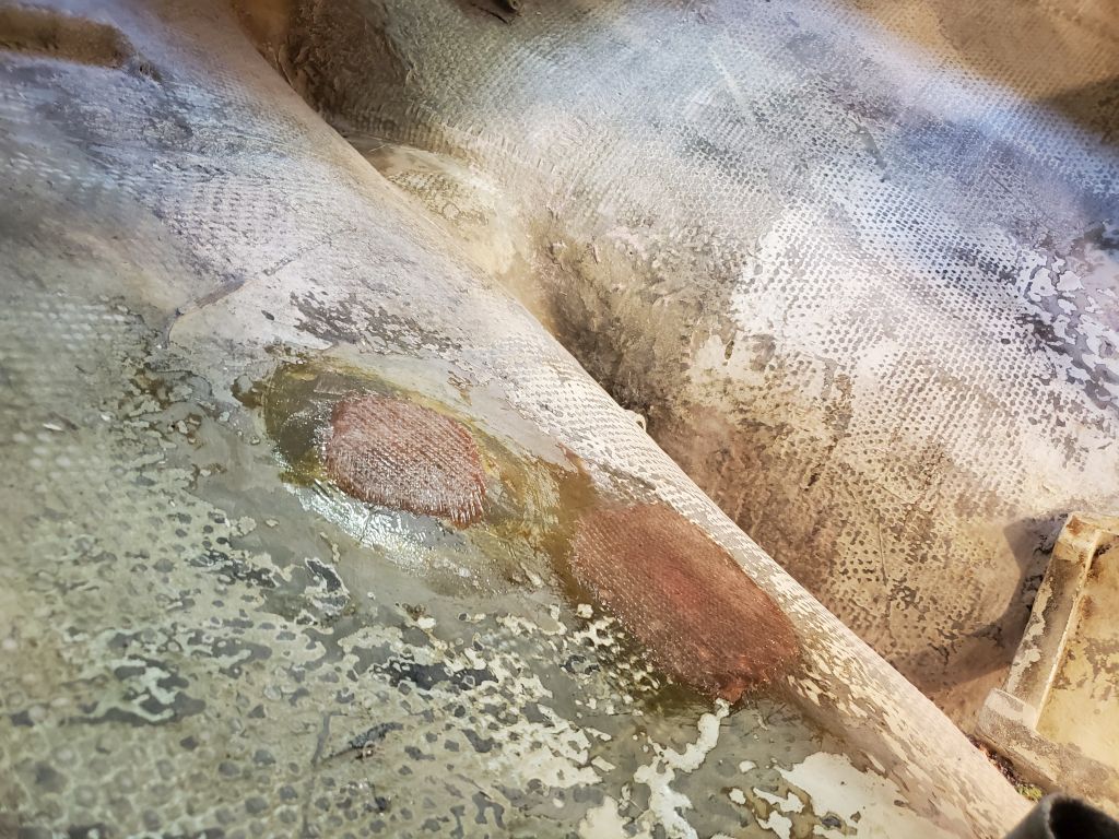
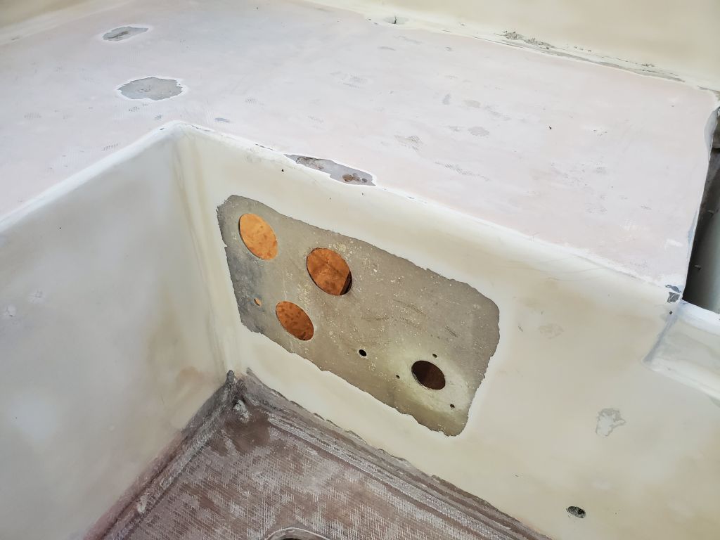
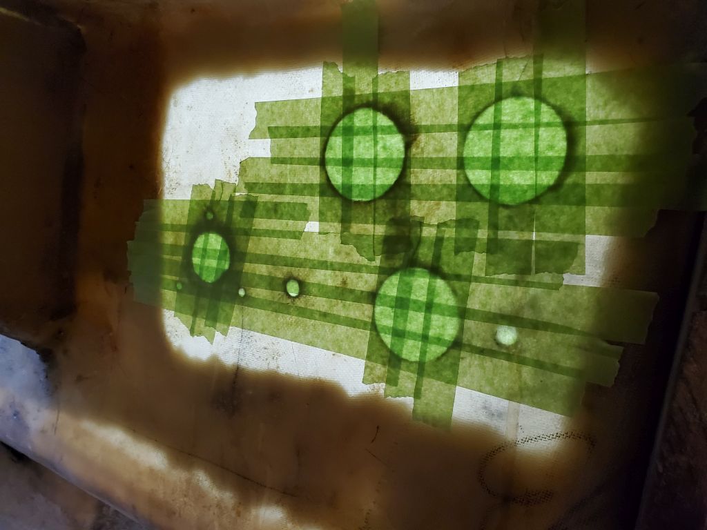
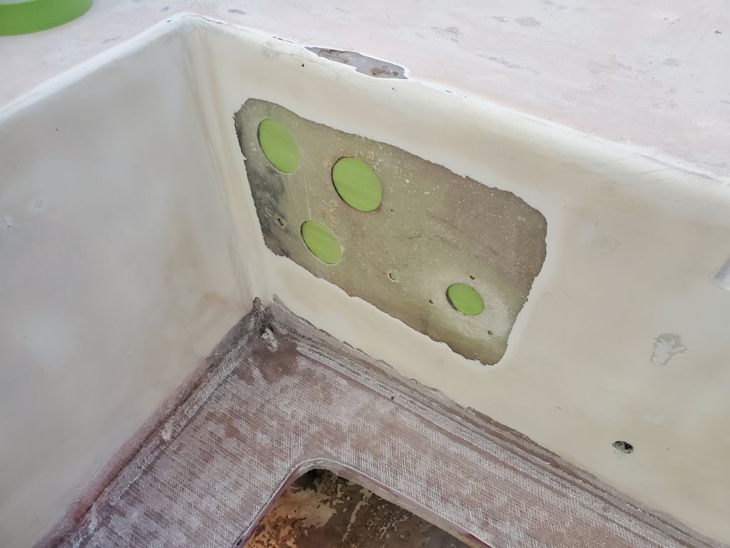
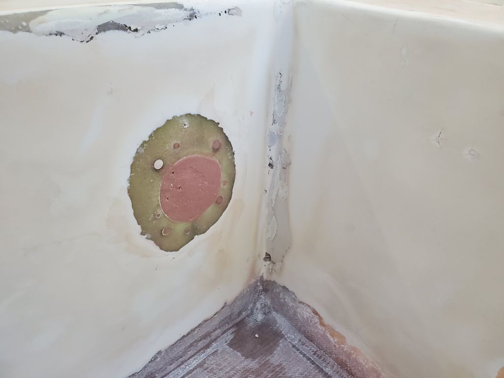
To prepare the round gauge holes and blower opening, I masked over from the back side, then filled the holes with a thickened epoxy mixture that I let partially cure while I cut fiberglass to fit. Then, with all basic and expected preparations complete, I installed the new fiberglass patches over the top of the two areas.
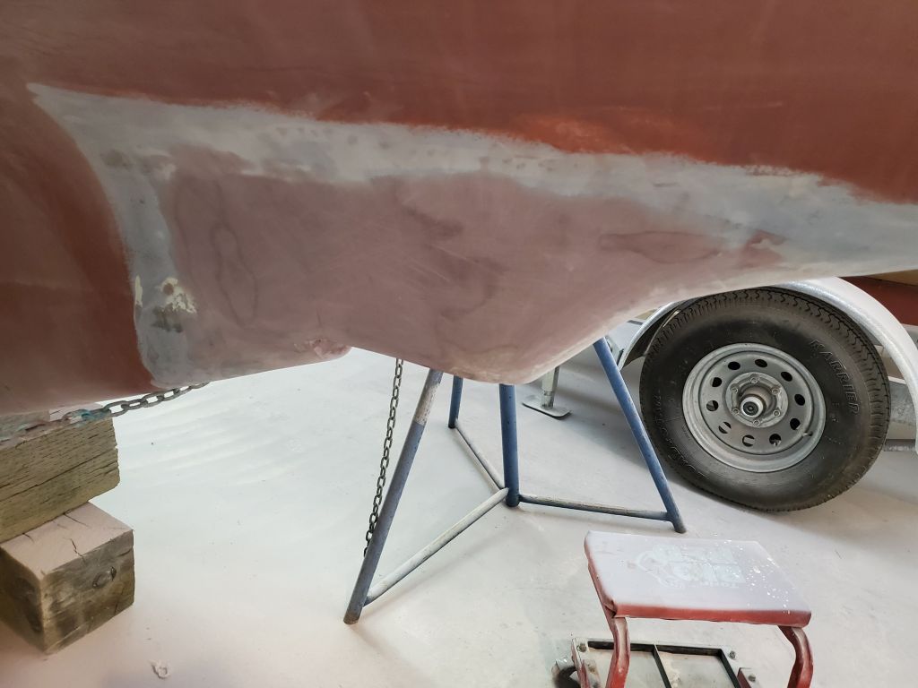
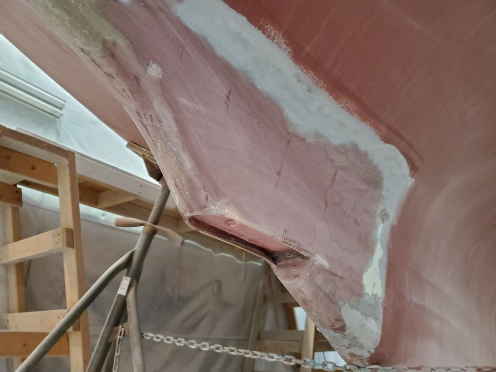
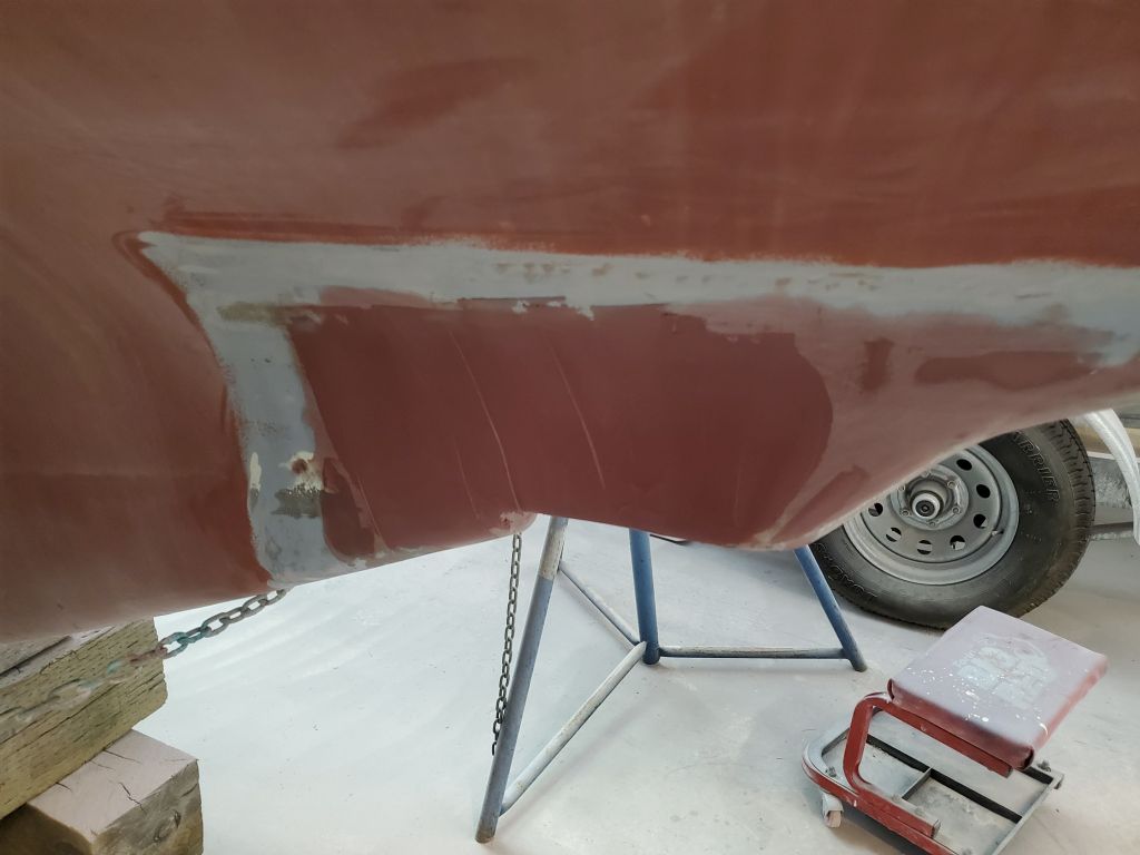
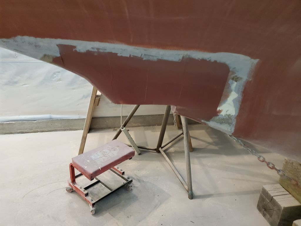
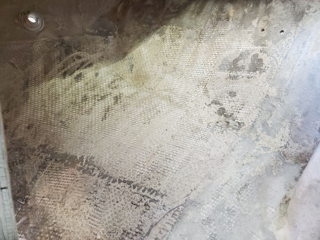
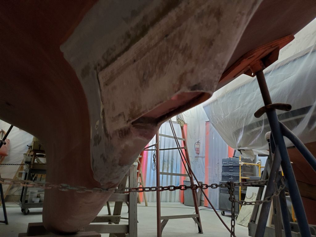
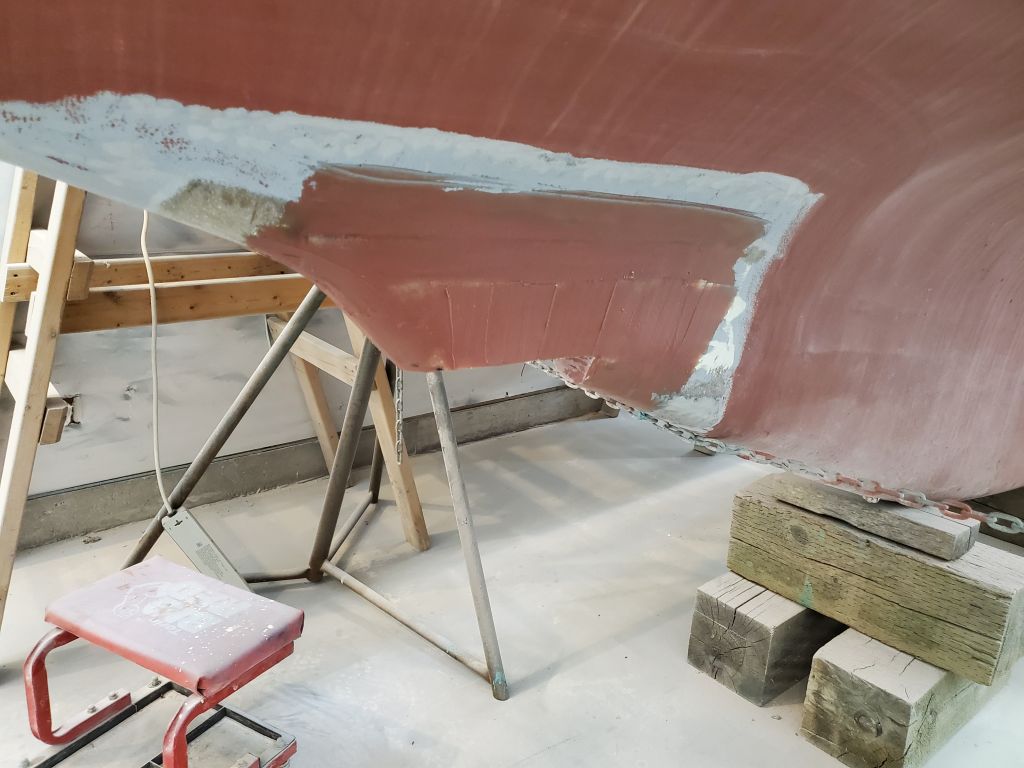
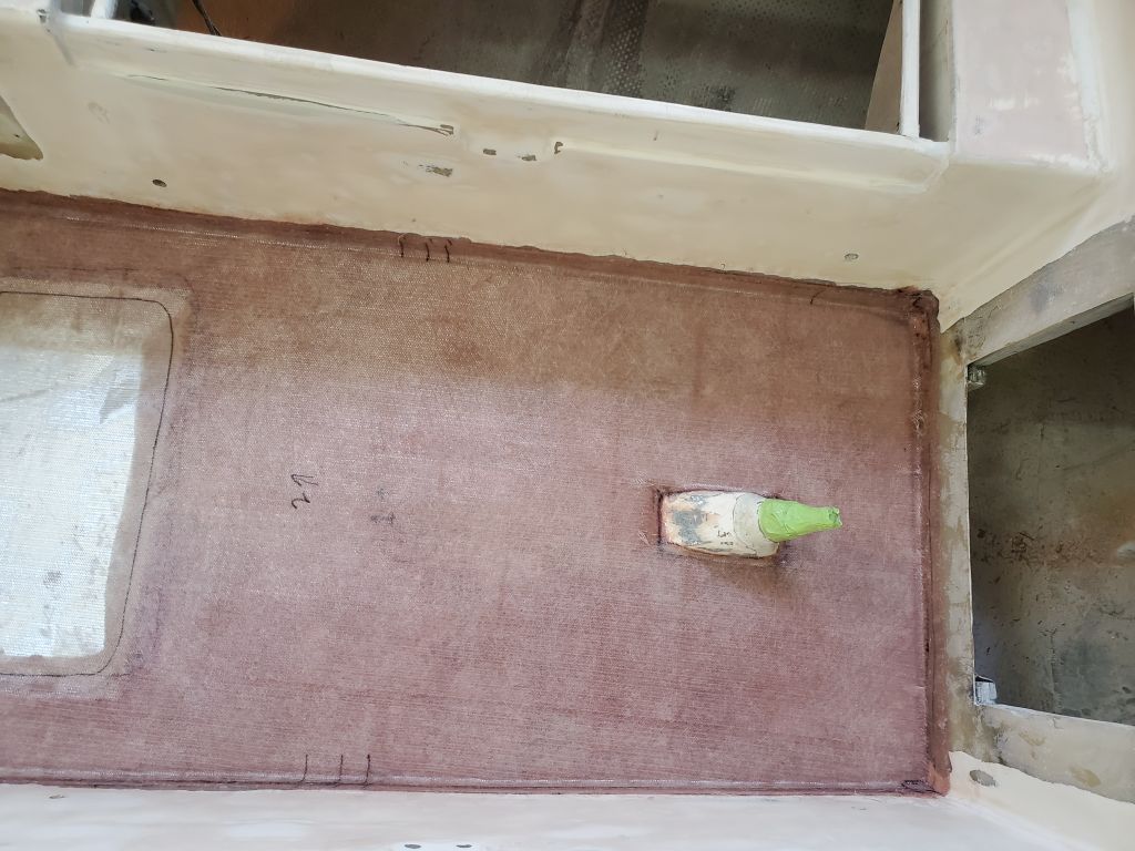
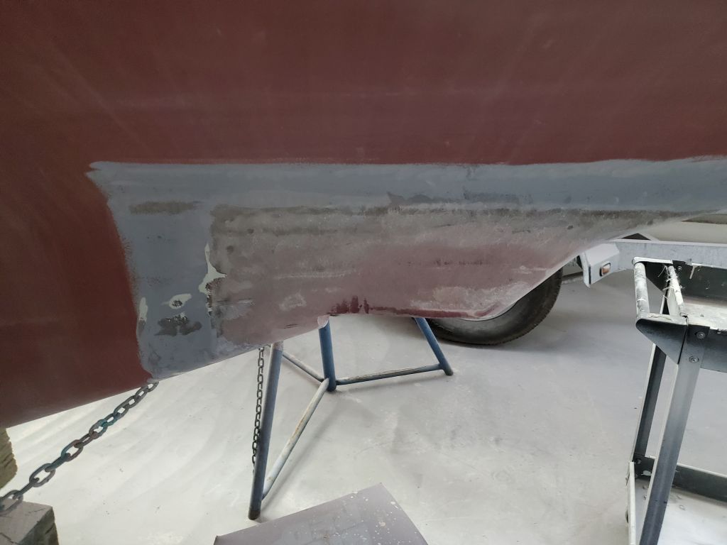
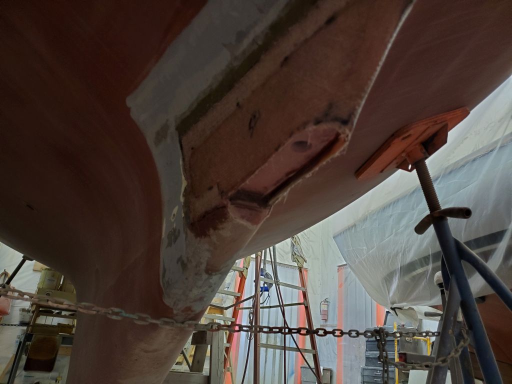
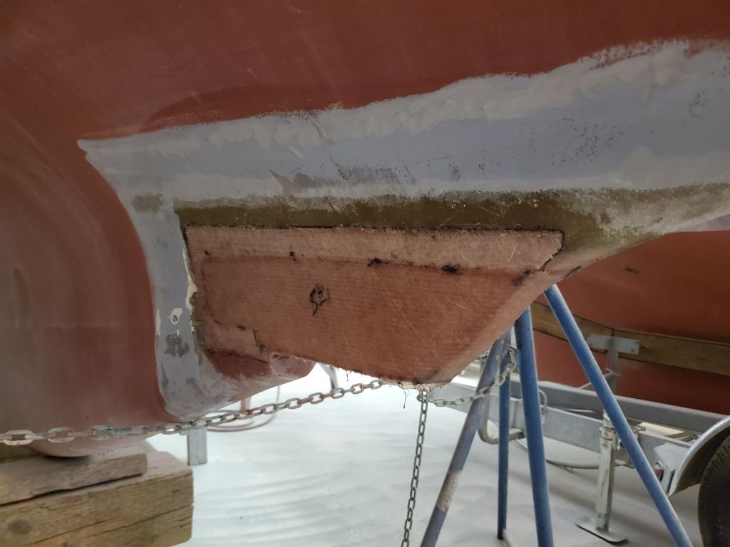
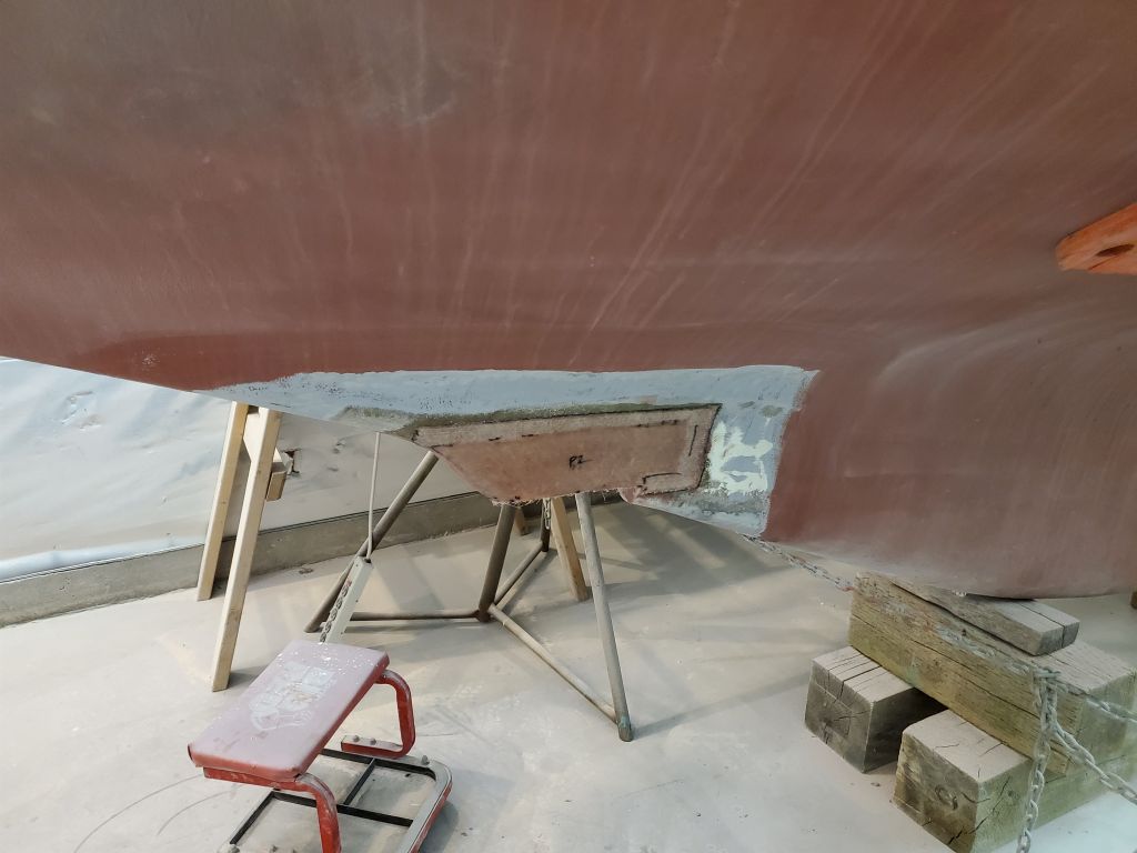
With the cockpit work complete for now, I turned to the transducer housing and, after a quick water wash, sanded the fresh fiberglass lightly as needed.
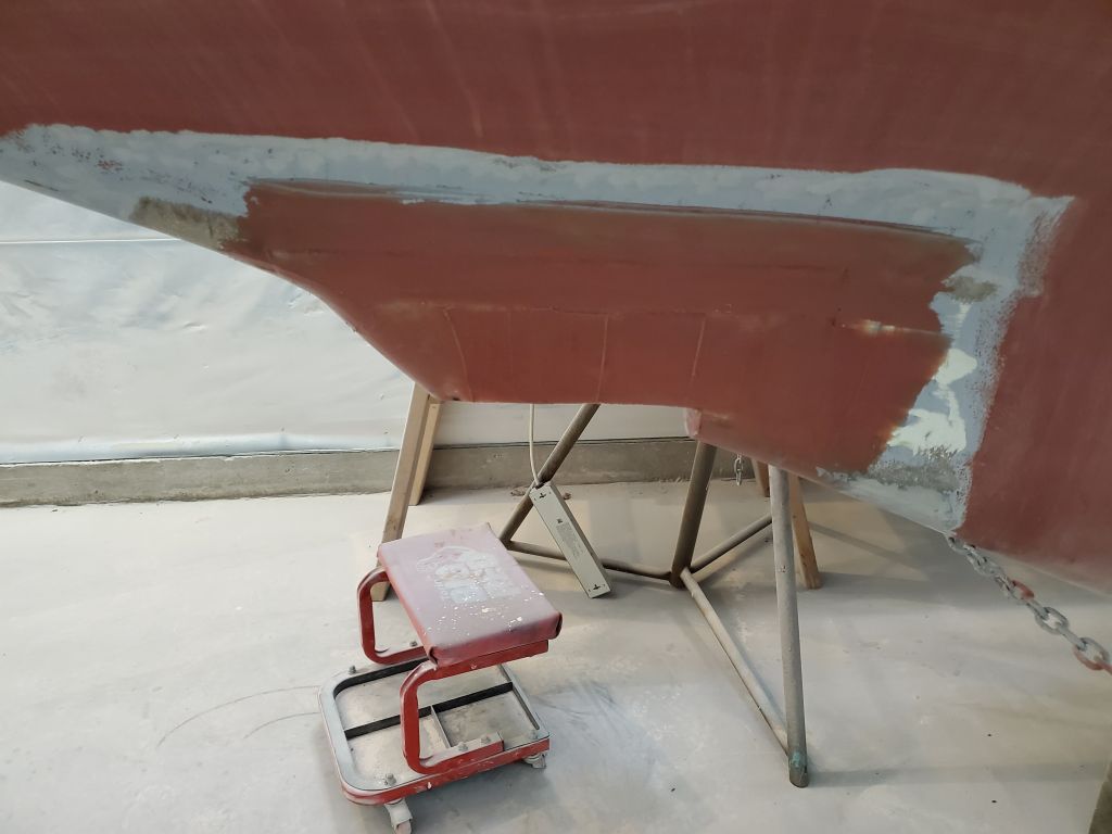
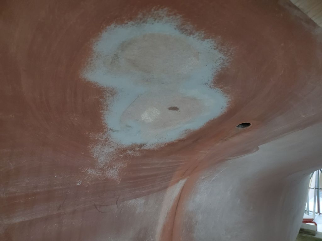
After cleanup, I applied a first coat of epoxy fairing filler to create the final shape of the new housing and tie the structural work into the surrounding hull.
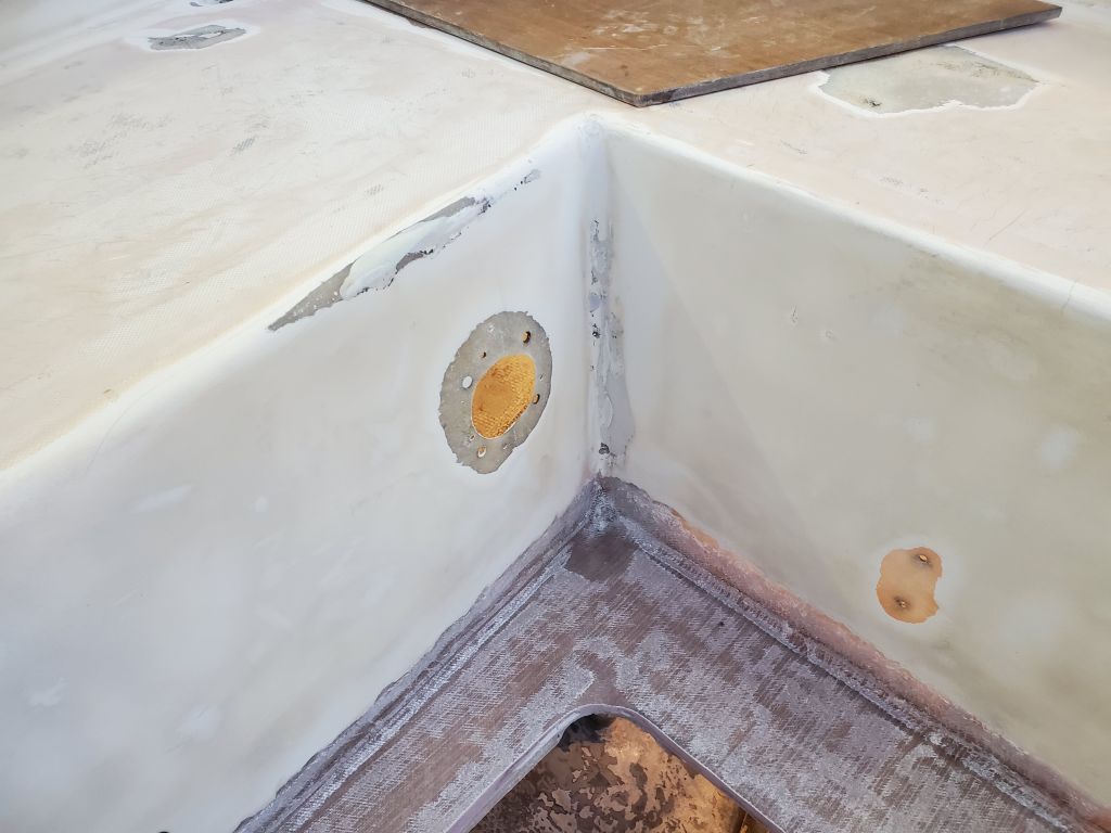
I installed some fiberglass to help reinforce the repair I’d made to the starboard cockpit seat scupper.
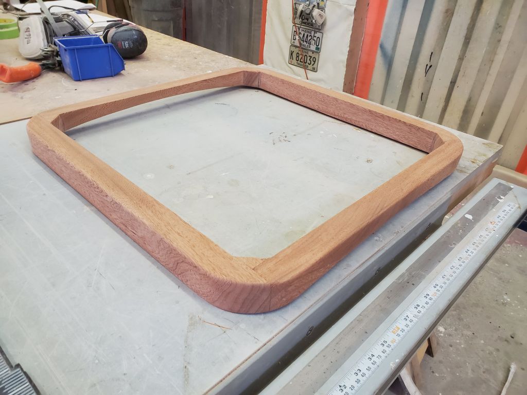
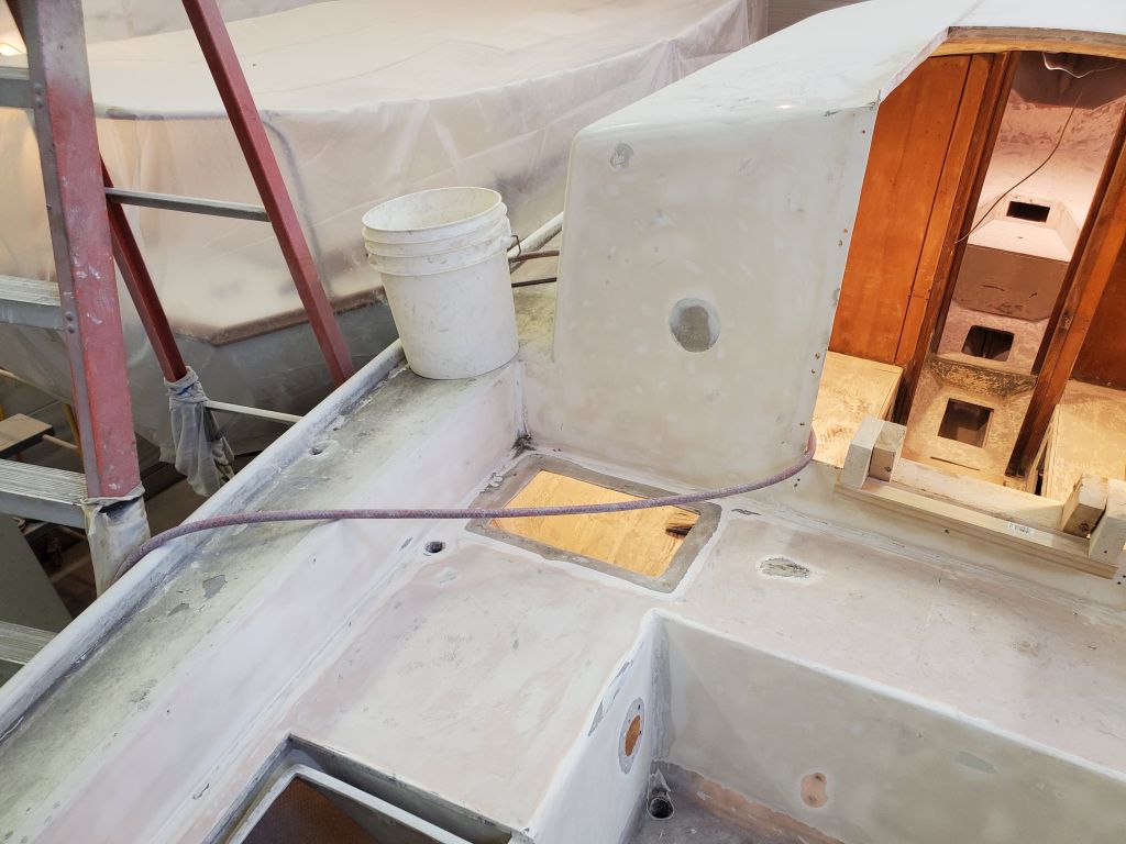
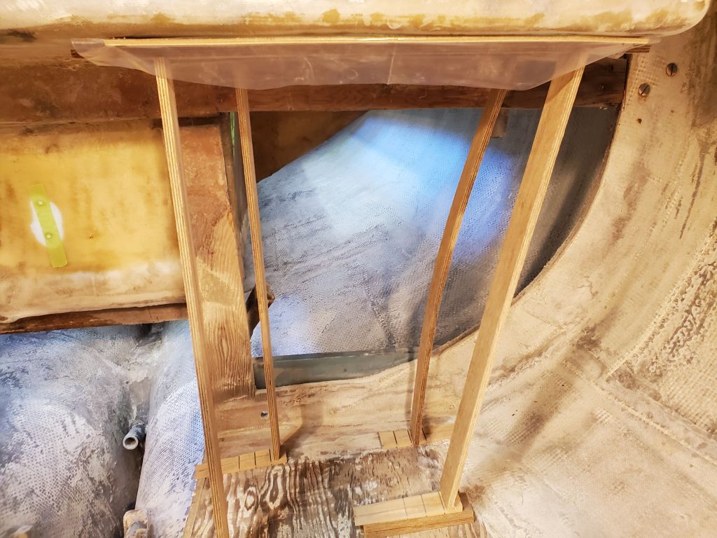
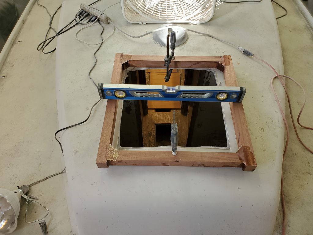
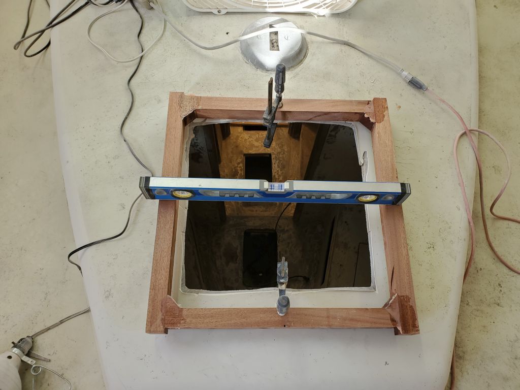
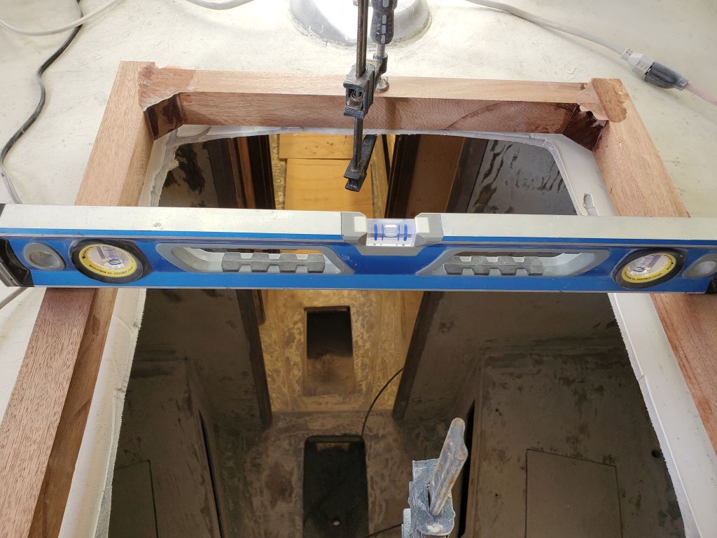
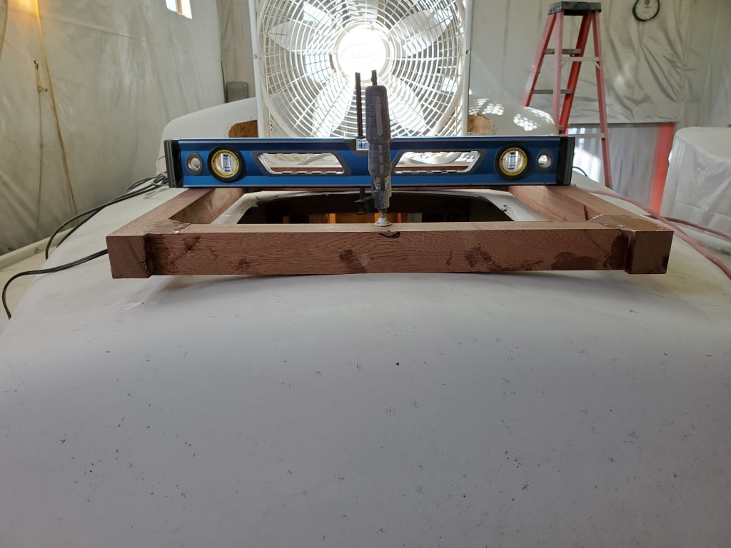
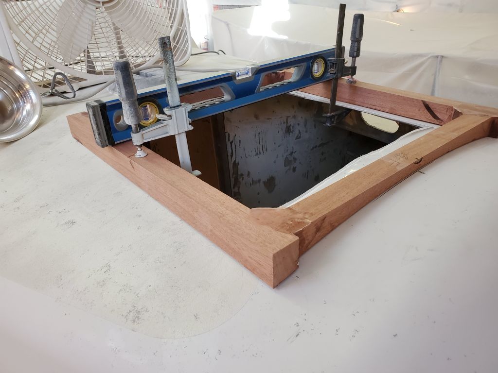
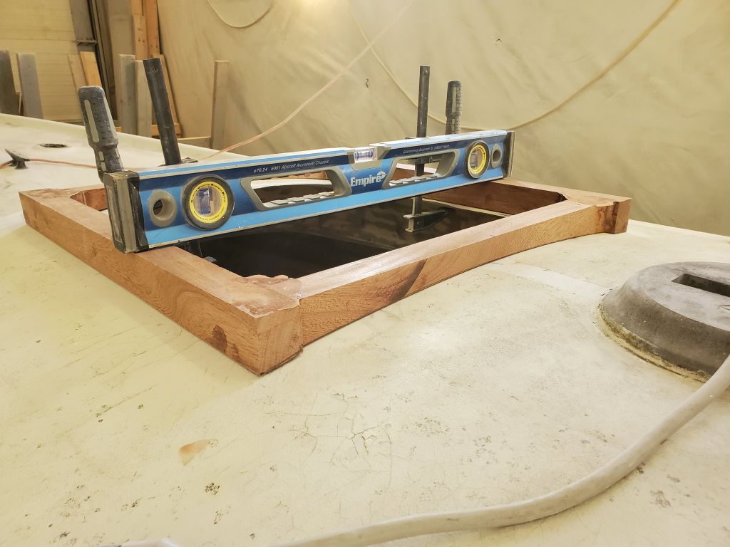
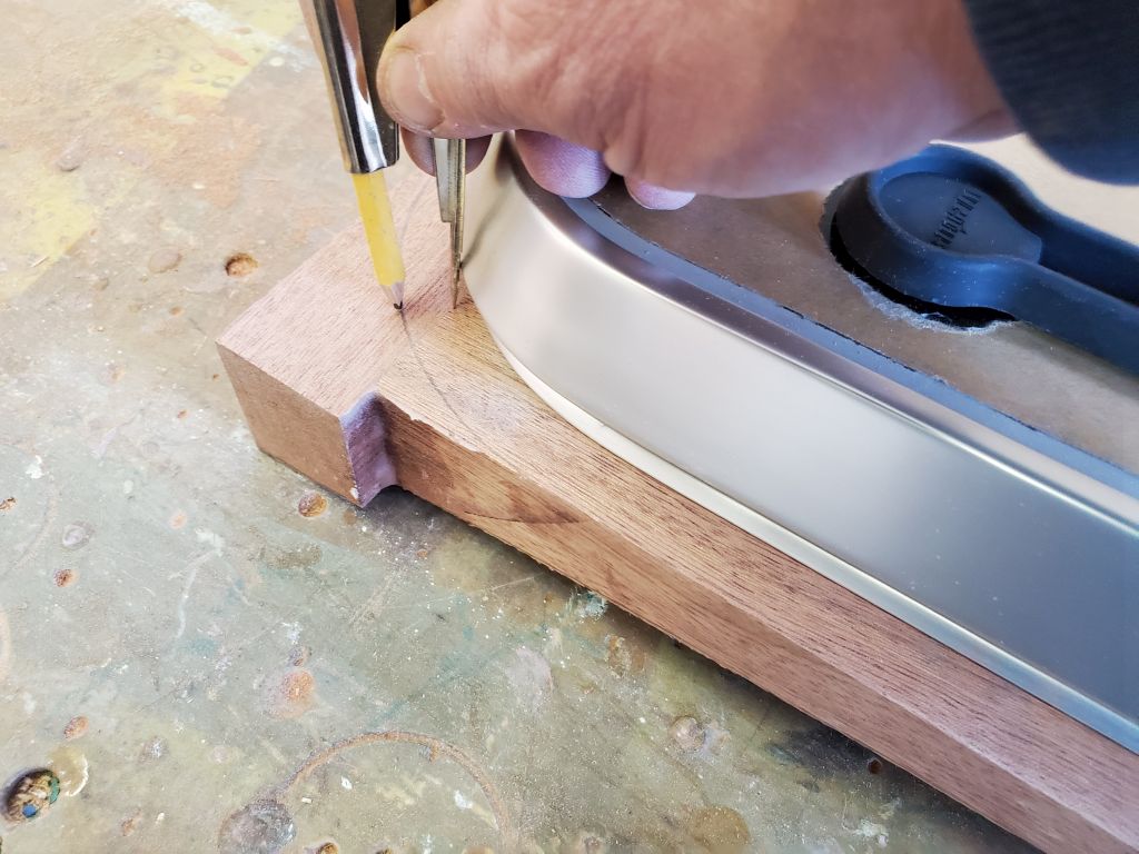
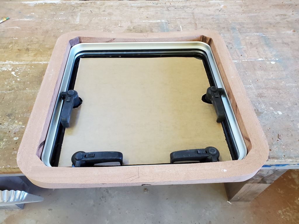
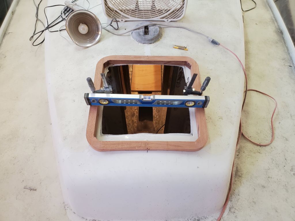
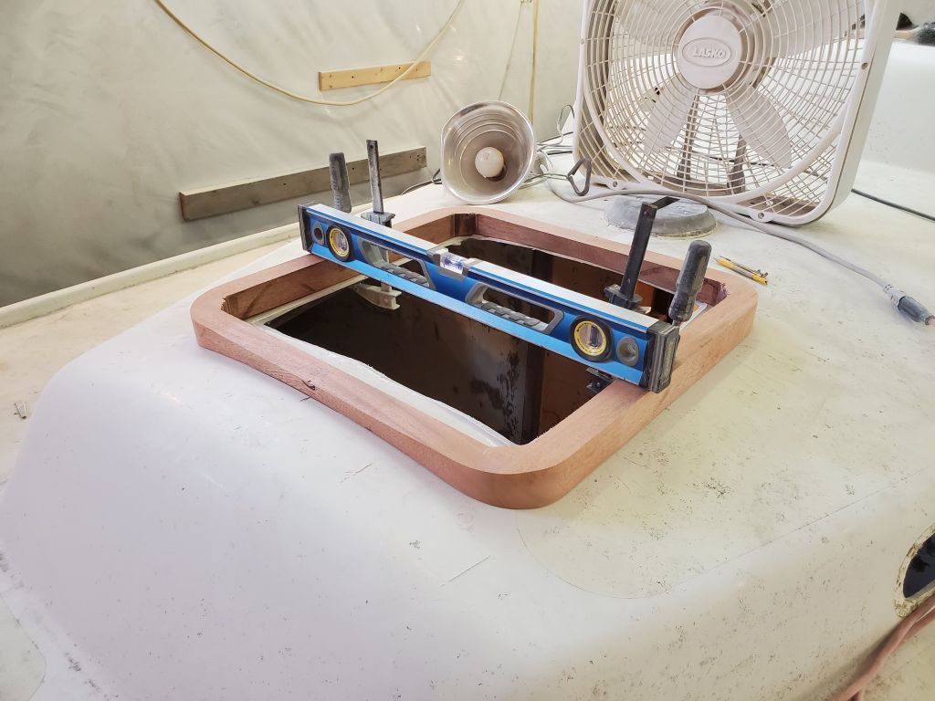
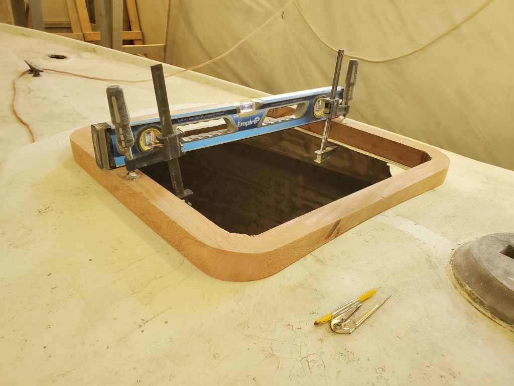
Now nearing the end of the day, I turned to the forward hatch frame. Placing the new wooden frame on deck in way of the hatch opening, I centered it and, with temporary clamps, held it in place level from side to side. Now I could scribe the camber of the deck onto the forward and after sides of the new frame so I could trim the frame to shape and fit the deck properly.
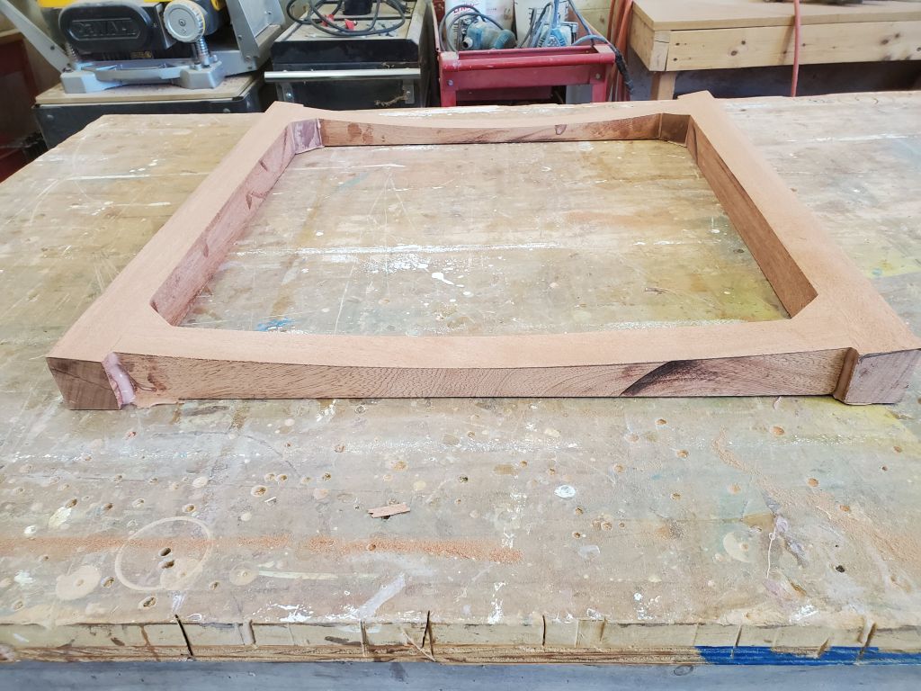
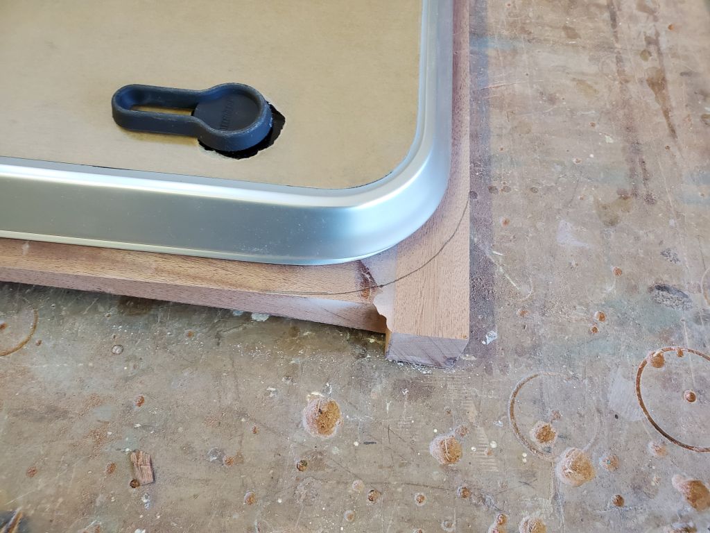
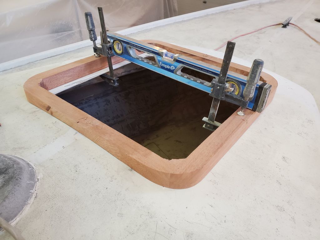
Thusly marked, I returned to the bench and made the curved cuts with a jigsaw, leaving the line and fine-tuning the curved shape with a sander thereafter. Then, I trimmed the longitudinal sides of the frame between the curved ends as needed, and test-fit the frame on deck once more. The newly-shaped frame fit well all around.
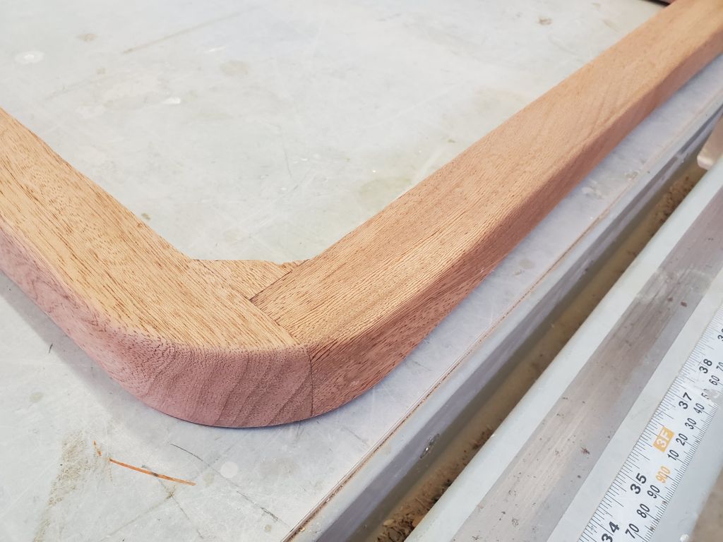
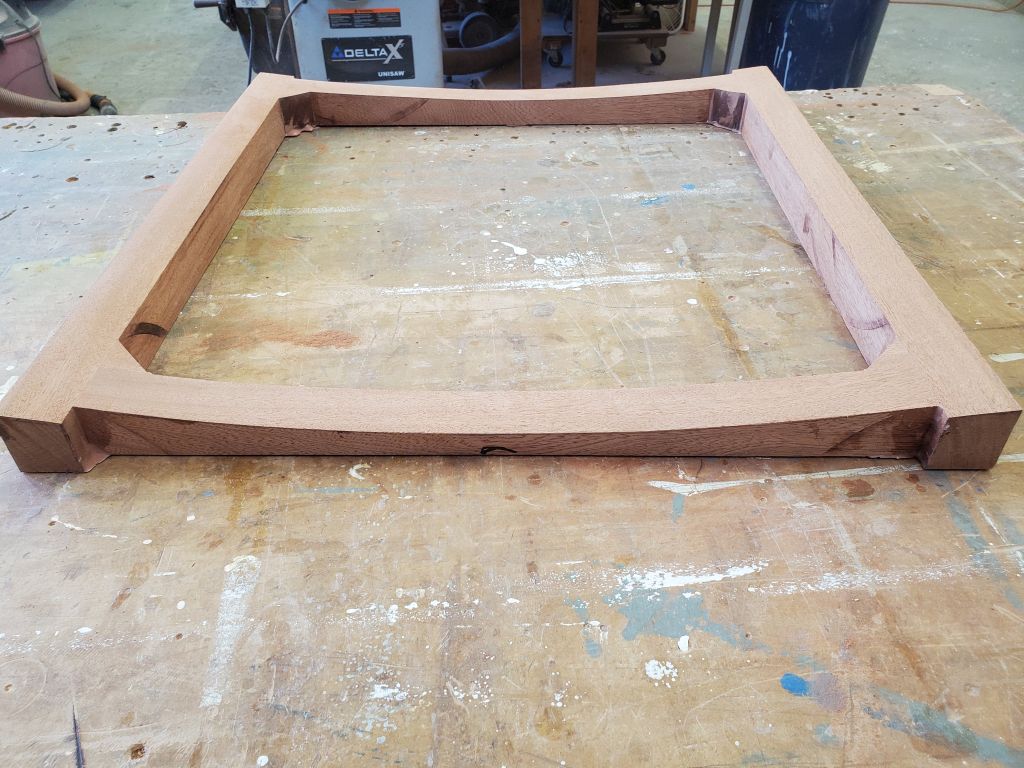
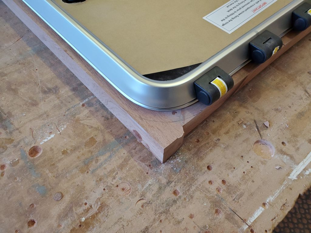
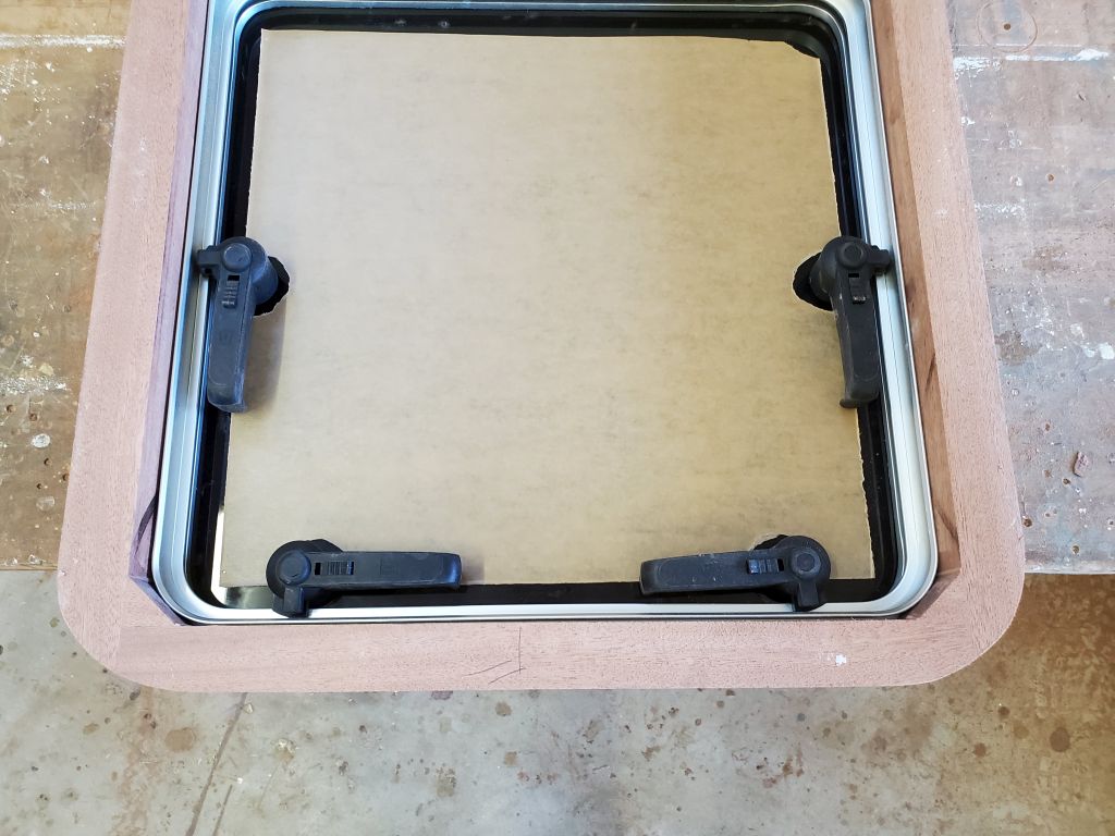
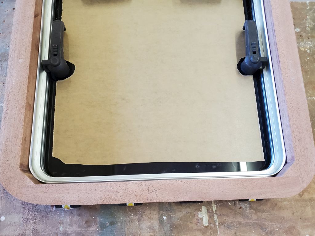
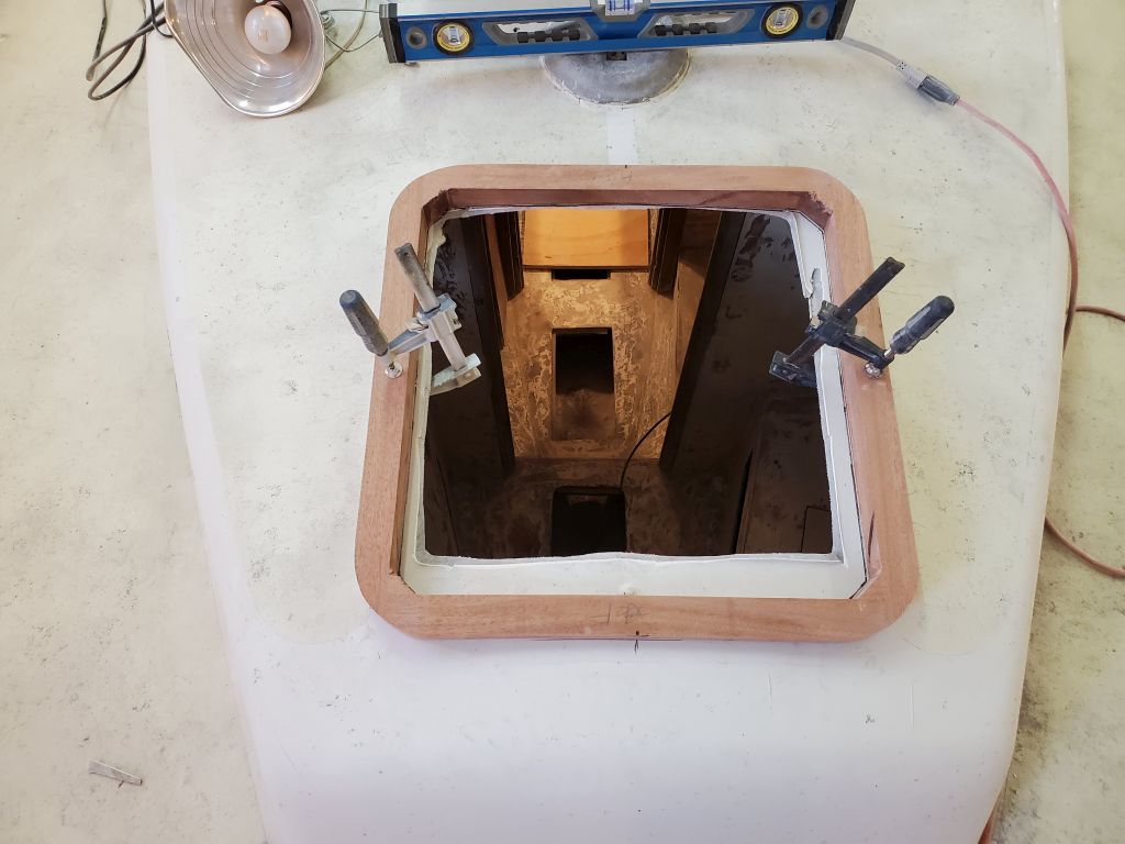
I placed the new hatch in the frame, and with a compass scribed the curves of the four corners, keeping a consistent reveal according to the straight sides of the frame. Then, I made the cuts with a jigsaw and sanded the final curves down to the line as needed.
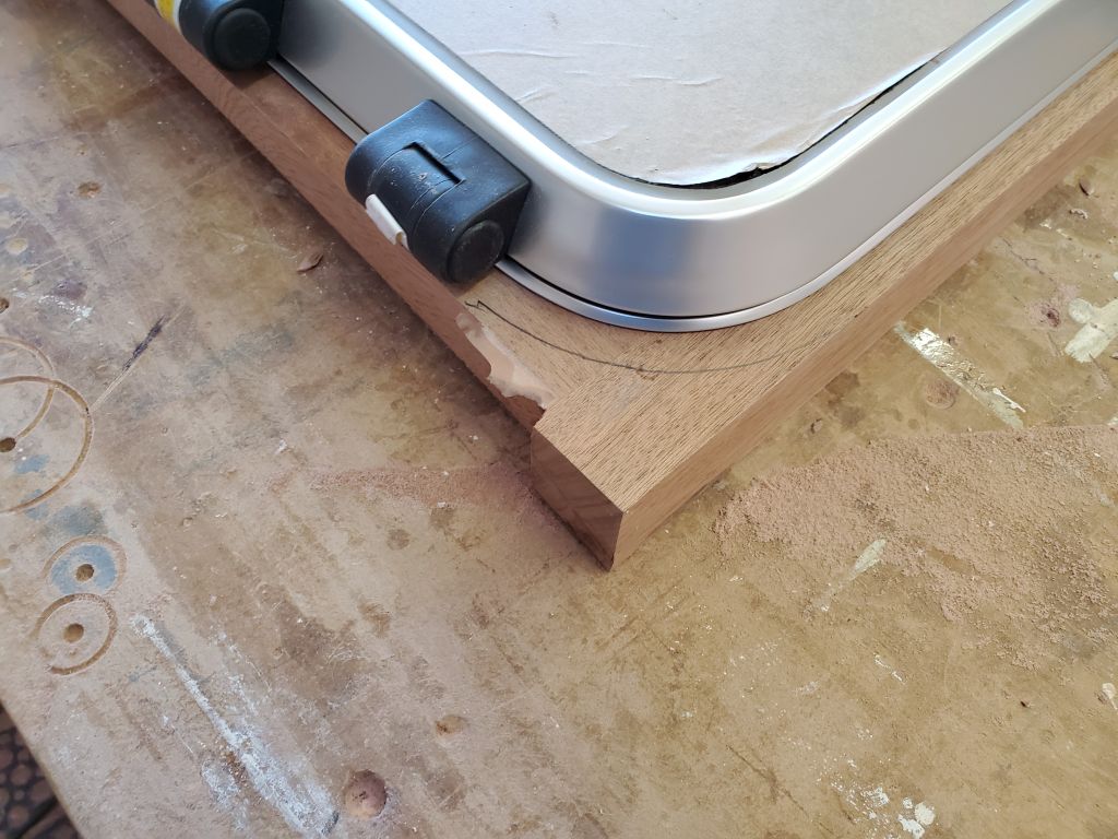
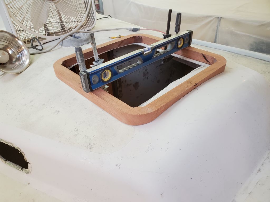
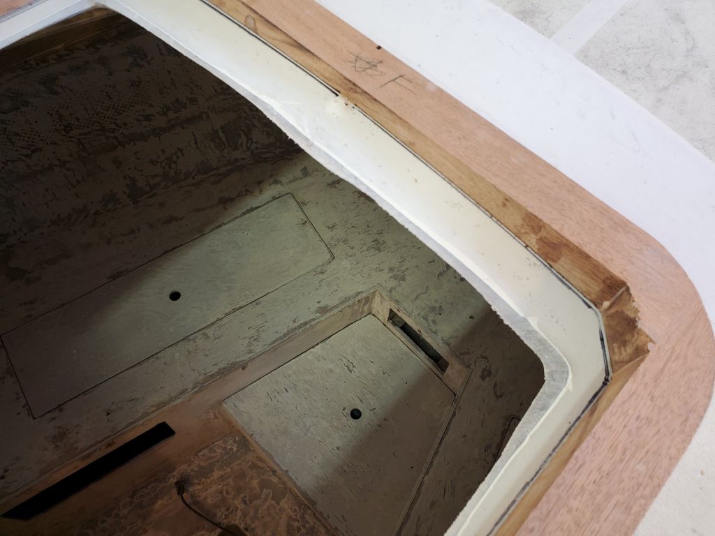
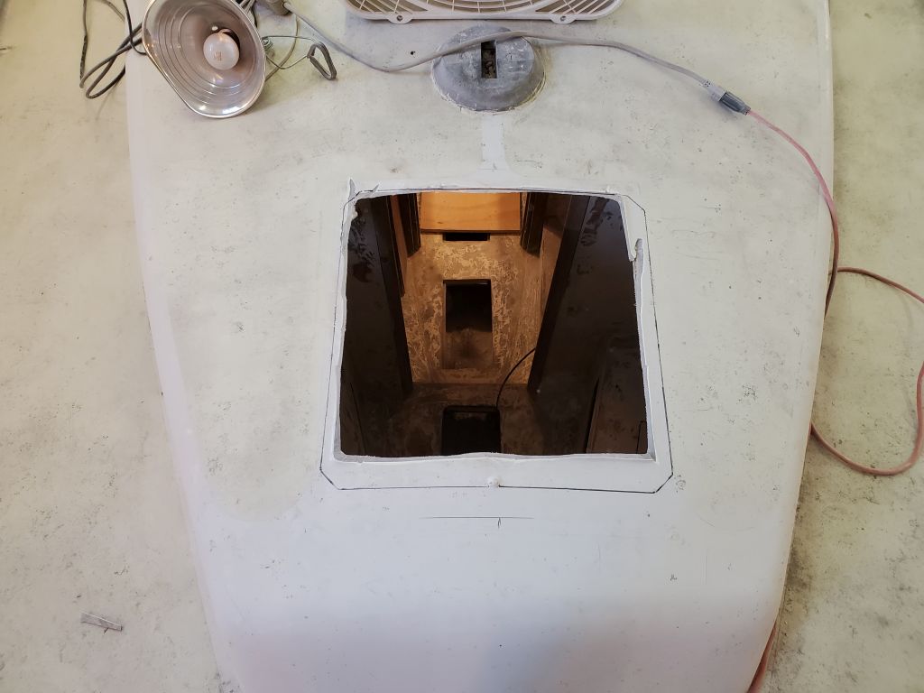
I checked the fit on deck once more, and, satisfied, marked the inside of the frame on the deck so I could make the final cutout to match the new frame. It was too late in the day to make the cut, so that would be for next time. To finish off the new frame before final installation, I planned to round over the top corners, then, apply some varnish to the piece before epoxying it to the deck when ready.
Total time billed on this job today: 6.75 hours
0600 Weather Observation: 16°, clear, 2-3″ snow down overnight. Forecast for the day: Sunny, 25°.
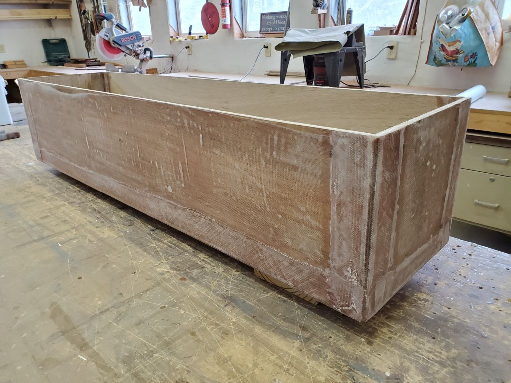
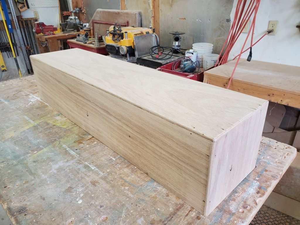
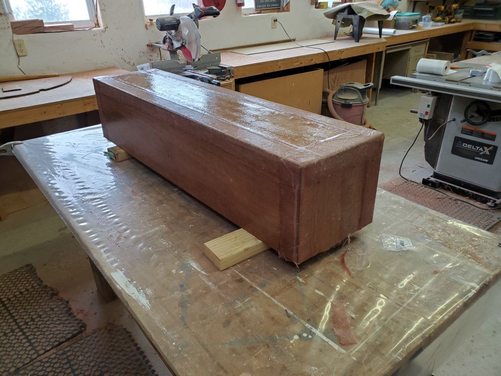
With the epoxy fillets cured sufficiently, I trimmed and removed the temporary wire ties from the edges of the box. Afterwards, I used a router to round over all the external edges of the box, for appearance, but more importantly to ease the corners for the fiberglass tabbing that would come next.
Next, I coated the outside of the box in epoxy.
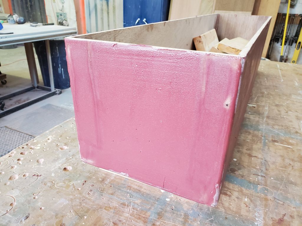
Now I installed biaxial tabbing on all the box corners, adding the structure that would help hold the box together. I sheathed the entire box between the tabbed corners with some 10 oz. cloth I had on hand; this would provide weatherproofing and durability. I left the fiberglass to cure overnight before continuing. Next would be filling and fairing to smooth the box and prepare it for finishing.
Total time billed on this job today: 1.75 hours
0600 Weather Observation: 21°, mainly cloudy. Forecast for the day: Cloudy, light snow in the afternoon/evening, 33°.
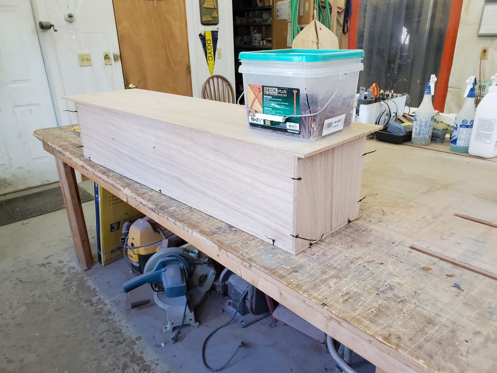
After various discussions in the weeks since I made up the rough idea of the deck box forward of the pilothouse, the owner requested that we make it a bit smaller, which I agreed with; I’d made it the size I had in order to try and fit the spare propane tank, but this did make the box larger than seemed appropriate, and another box–to be built in the cockpit–could hold the propane tank.
Needing to keep the box construction underway, since there were several other boxes on deck I hoped to conceive and build before the season, I milled the various plywood pieces down to the new size, taking off 2″ in overall height, and about 3″ in width. These dimensions seemed like they’d fit the space better overall, even at a net loss of storage capacity.
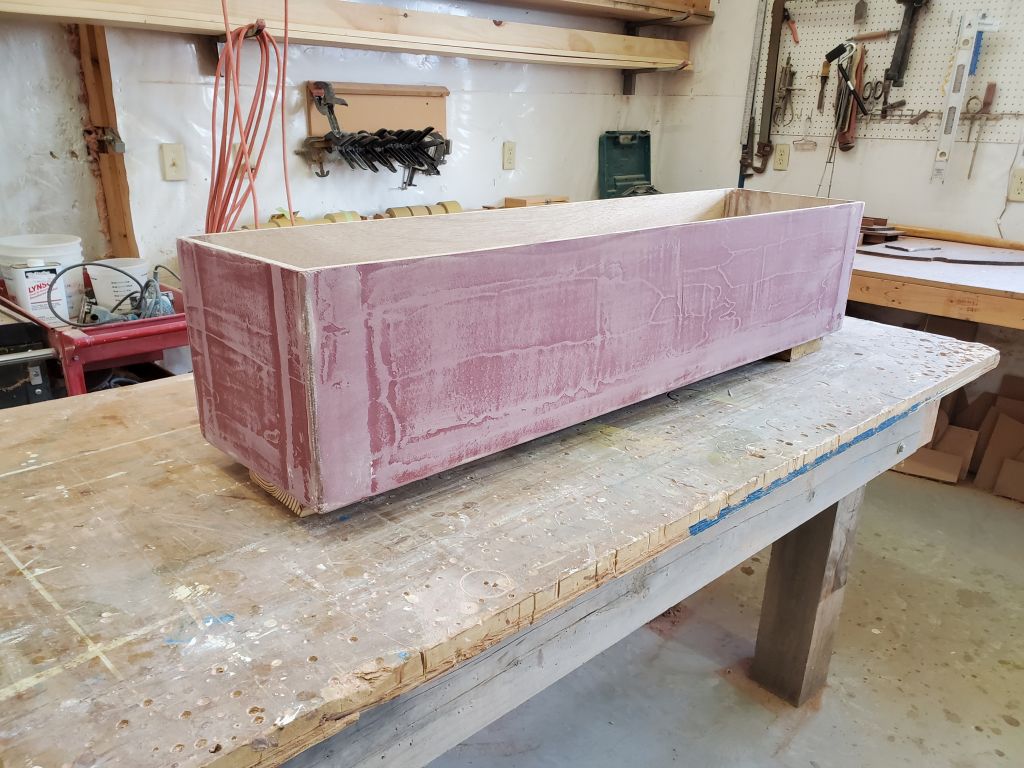
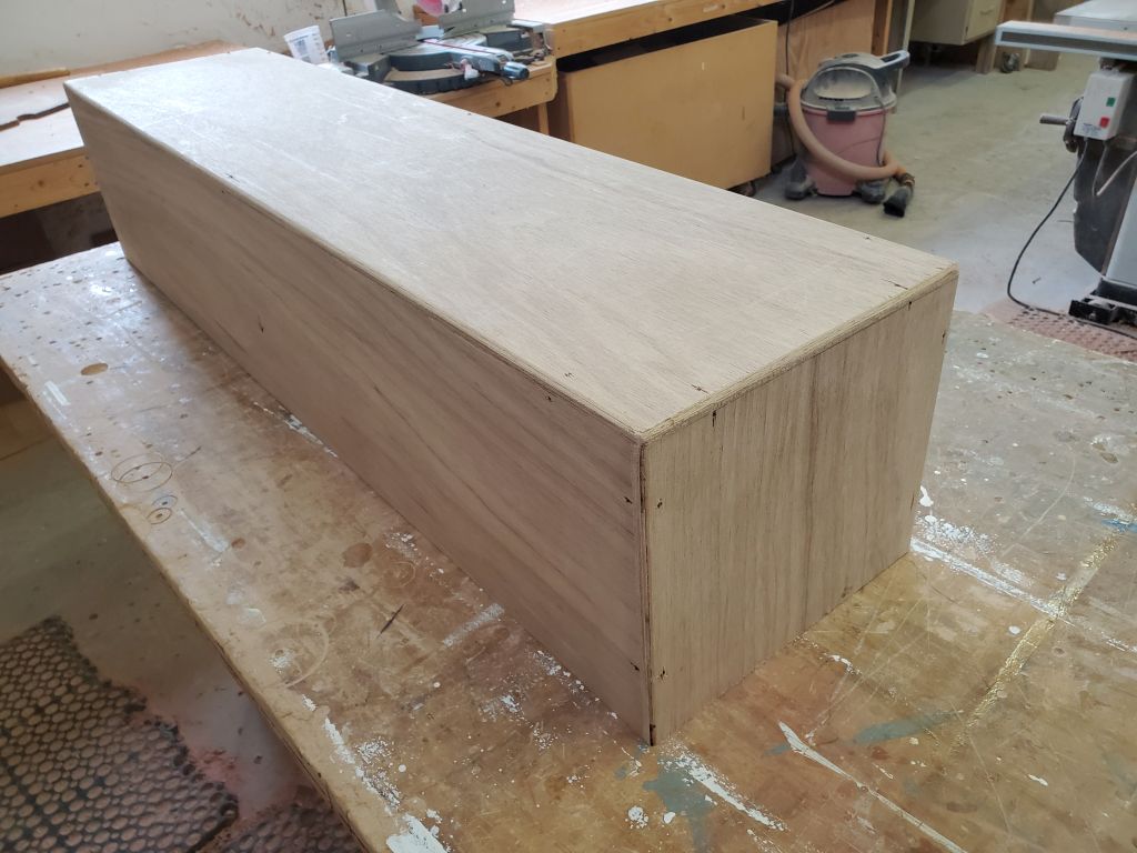
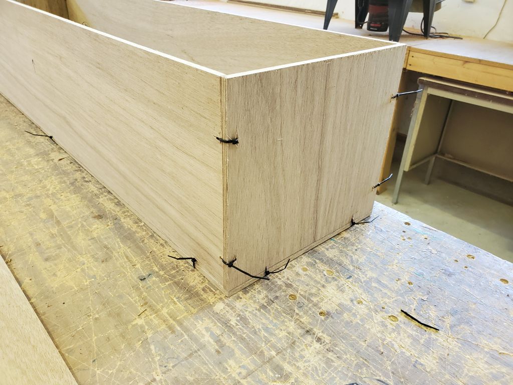
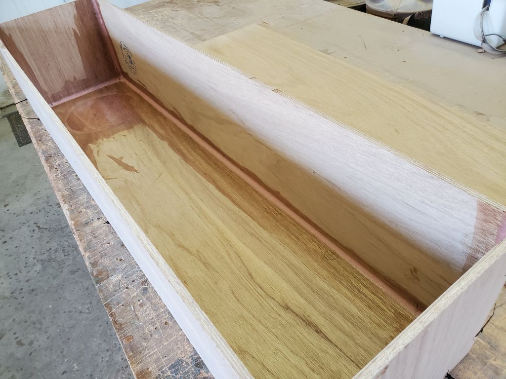
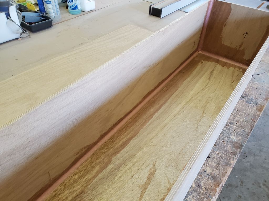
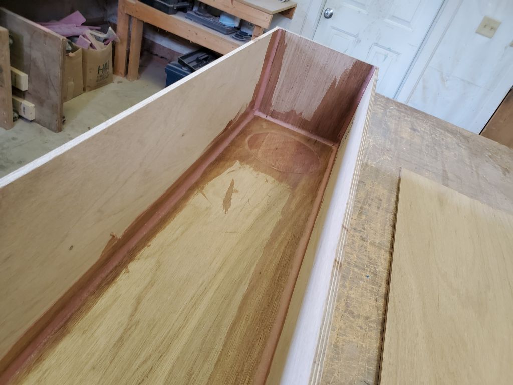
With the pieces newly cut, I secured the box together with small plastic wire ties through holes I drilled at the corners of each seam all the way around–my version of stitch-and-glue.
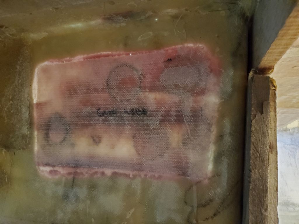
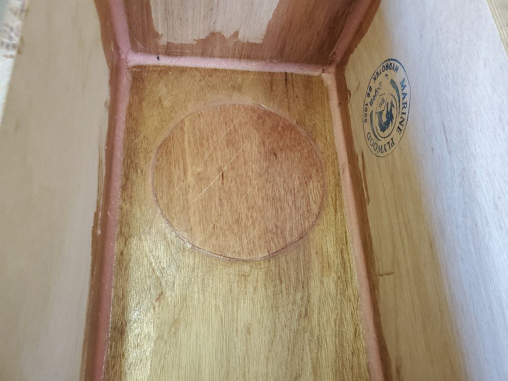
With the sides and bottom of the box held tightly together, I installed epoxy fillets on the inside of the box to permanently glue the box together and, once cured, hold things securely enough to allow me to reinforce the joints with fiberglass. I filled in the recess I’d milled in the bottom for the propane tank, using a round of 1/4″ plywood and epoxy to do so, rather than waste the bottom I’d cut previously. Because the assembled box had a slight propensity to rock, probably because of a slight warp to the plywood, I added some weight on top while the epoxy cured to keep the box flat to the bench. (After I took the photo I added weight to the opposite end also, for good measure.)
Total time billed on this job today: 1.75 hours
0600 Weather Observation: 30°, cloudy, snow shower or two. Forecast for the day: Clearing, 35°.
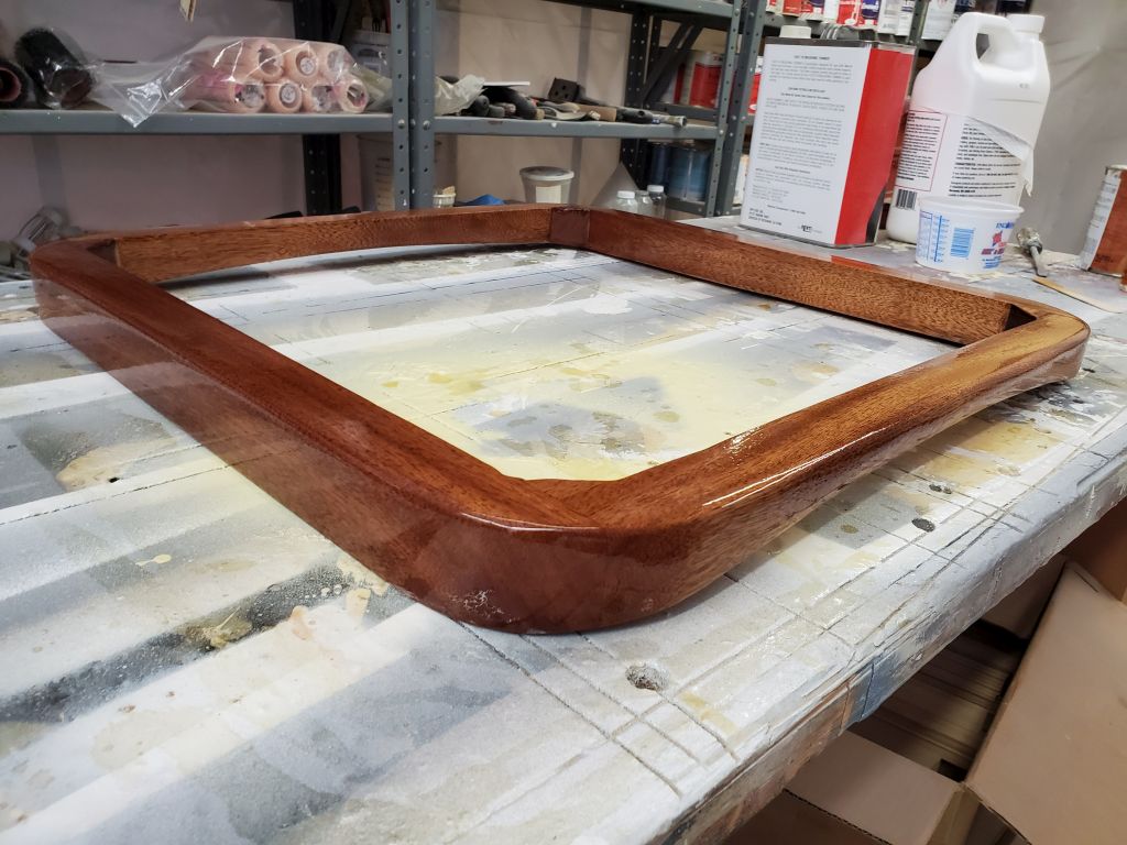
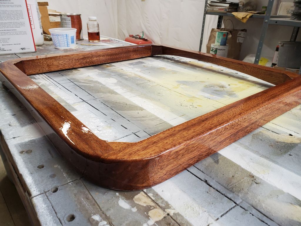
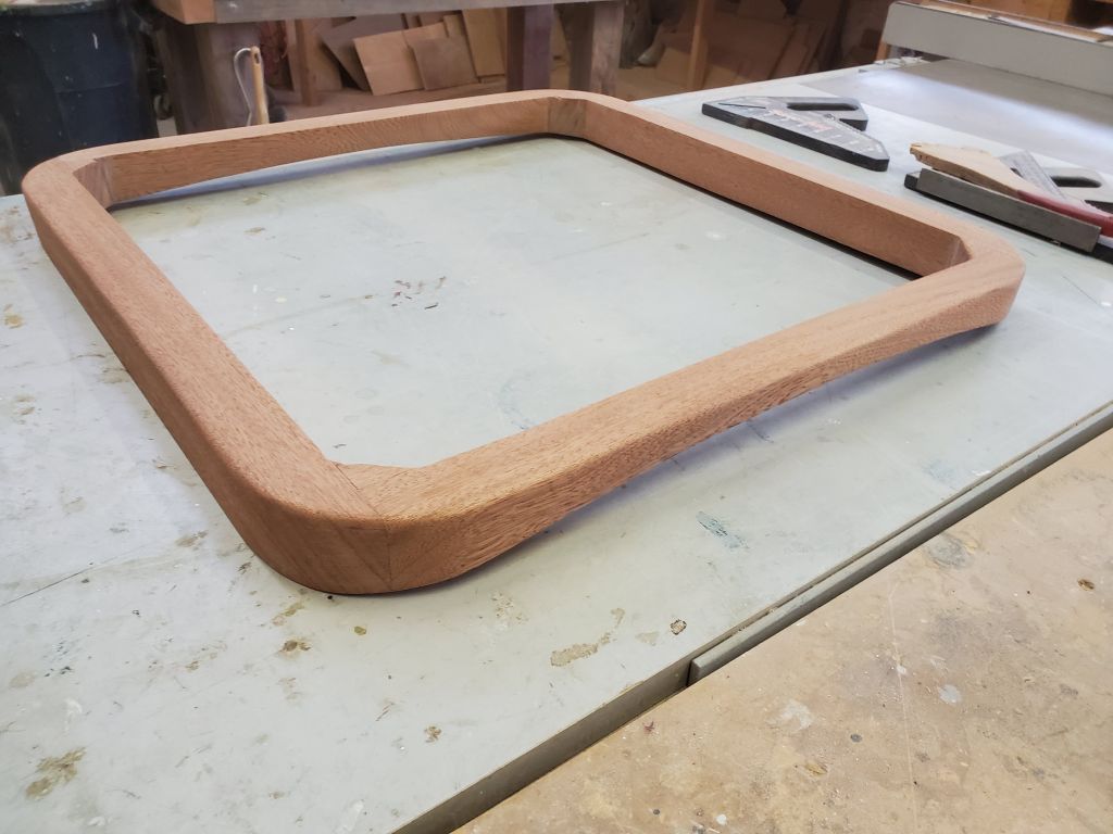
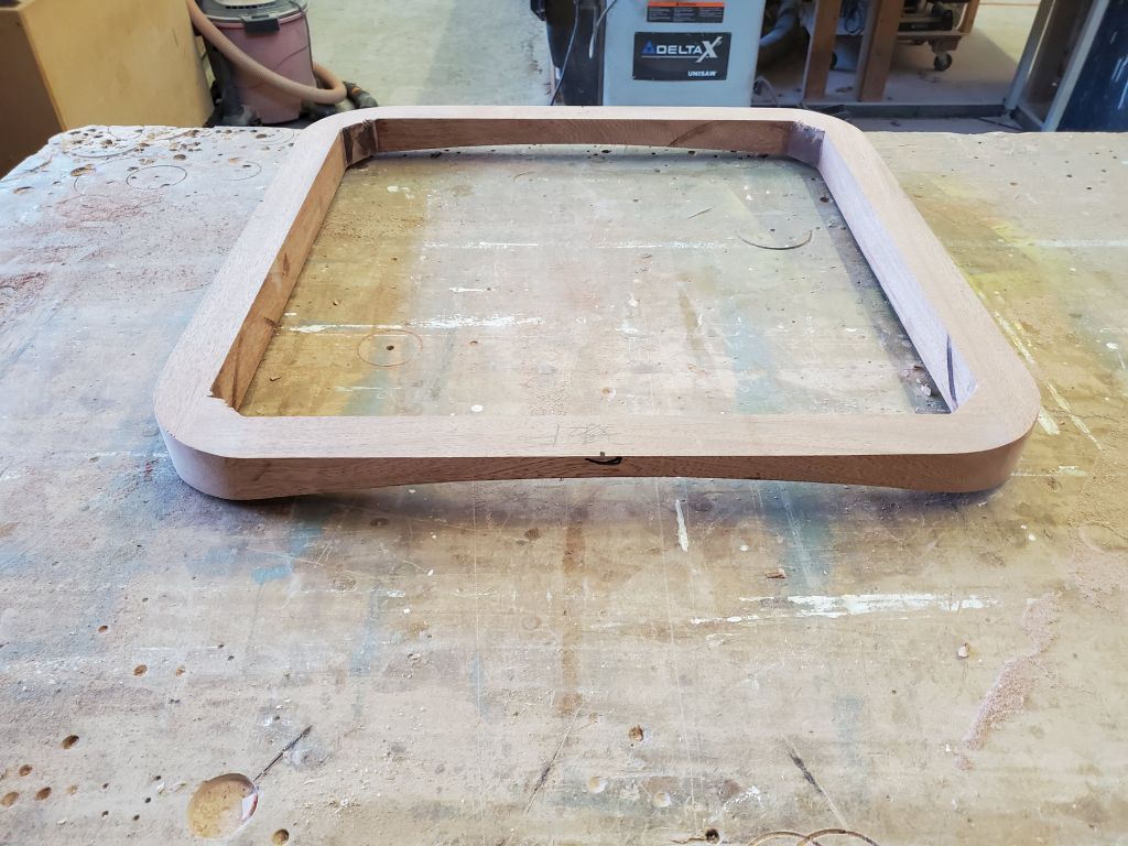
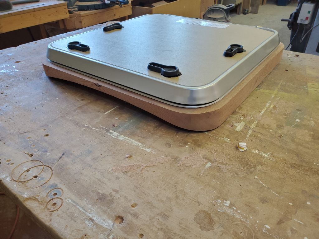
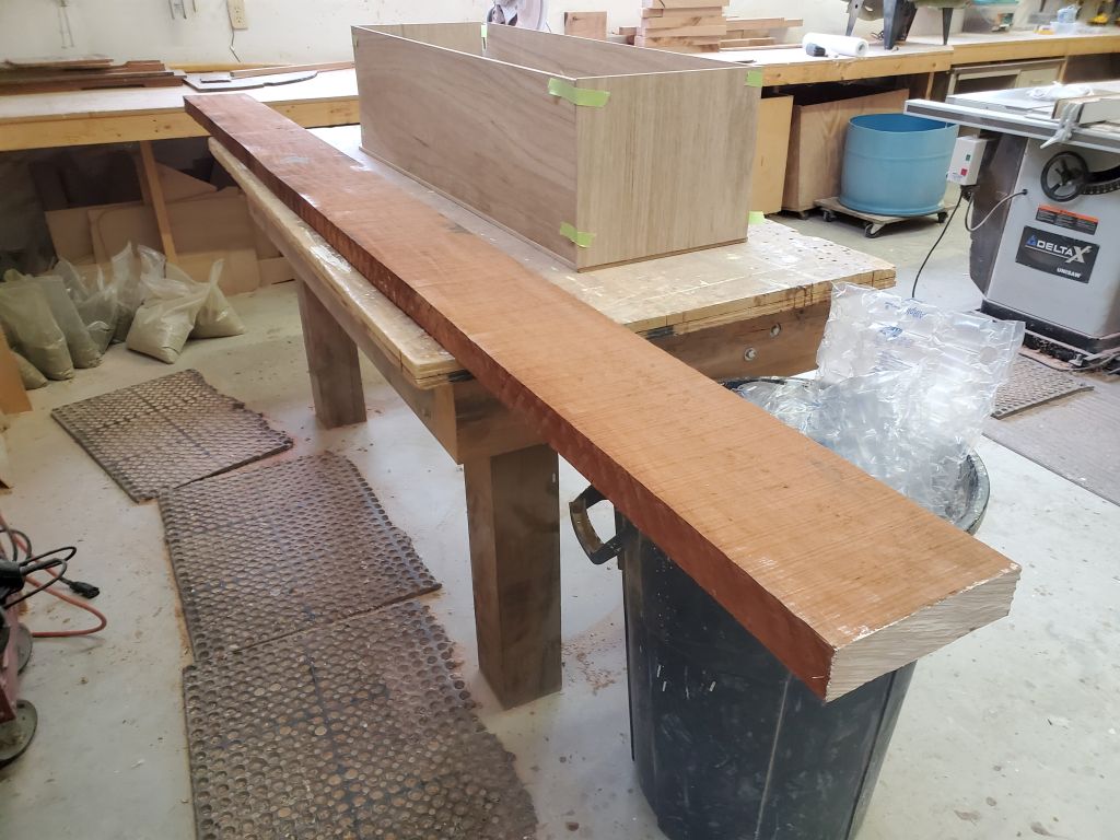
To further advance the project in the coming week, I spent some time over the weekend preparing the stock for, and gluing up, the frame for the new forward hatch.
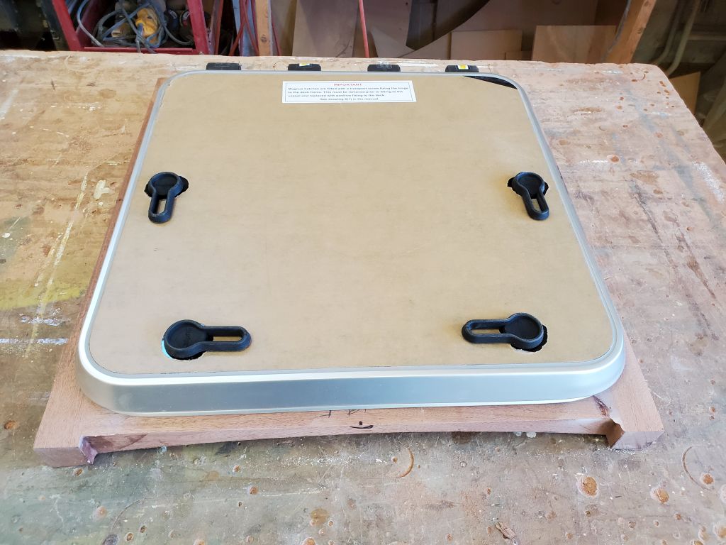
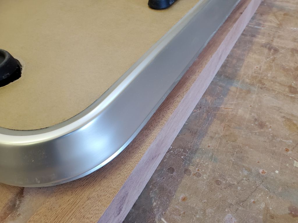
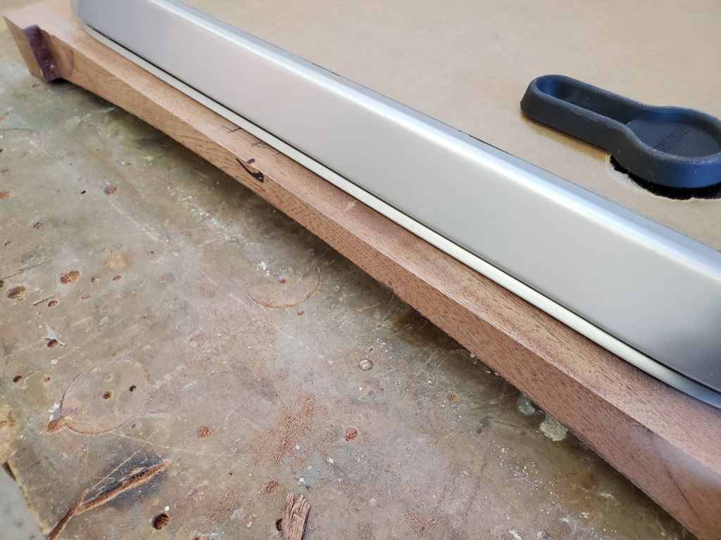
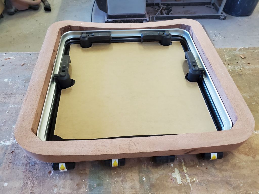
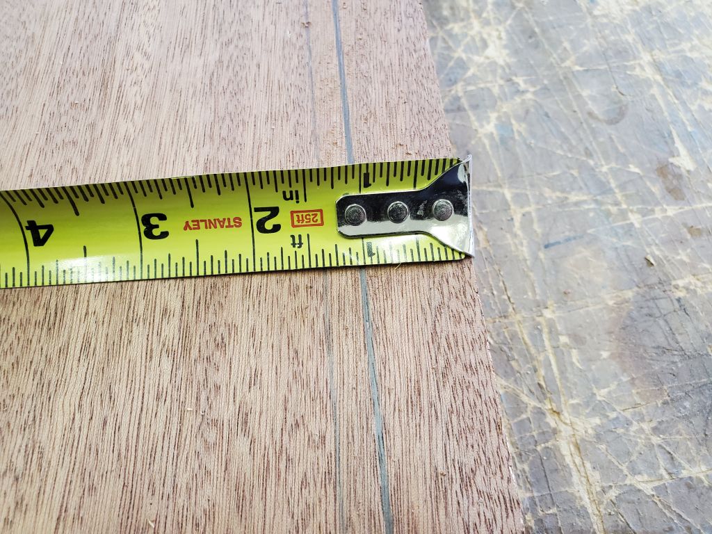
Using the hatch as a guide, I determined how much the hatch flange would overlap the frame: 1″ all around. I decided on a 1/2″ reveal, so that meant I needed to mill the stock to 1-1/2″ width. In due course, I milled a long blank from the original board to these dimensions.
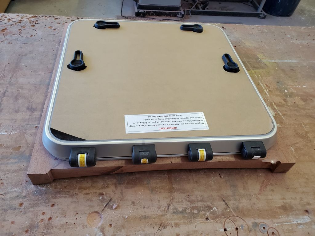
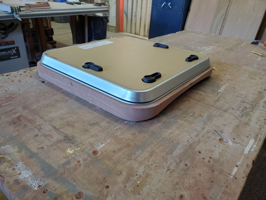
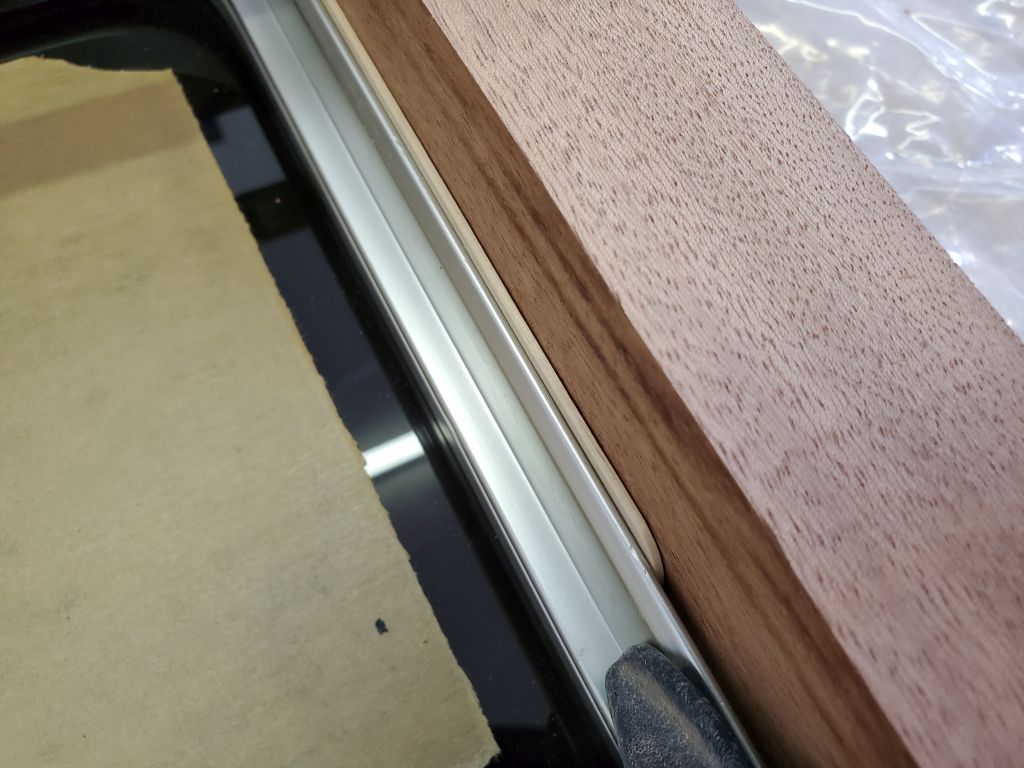
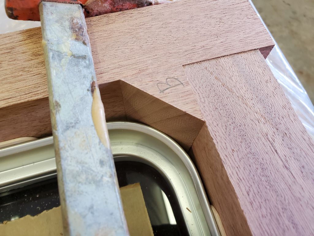
Using the hatch itself, I cut four pieces of the newly-dimensioned lumber to frame the hatch properly. I used tongue depressors as spacers between the hatch and the wood to provide a bit of leeway and provide for a close, but not overly tight, fit, and left two of the frame pieces overlong to make layout easier and since the corners of the frame would later be trimmed to a curve that matched the hatch radius anyway.
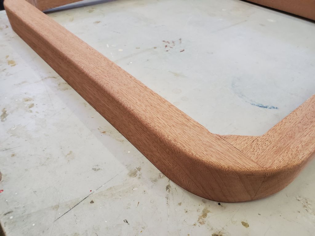
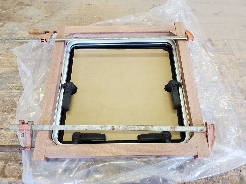
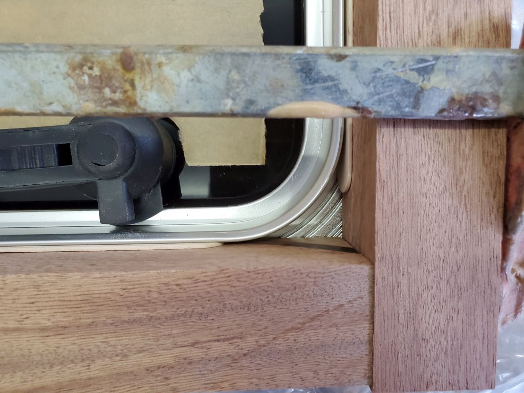
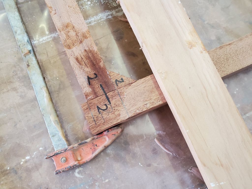
At the inside corners of the frame, I cut angled bits of wood to fit closely to the hatch curvature.
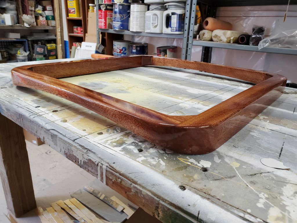
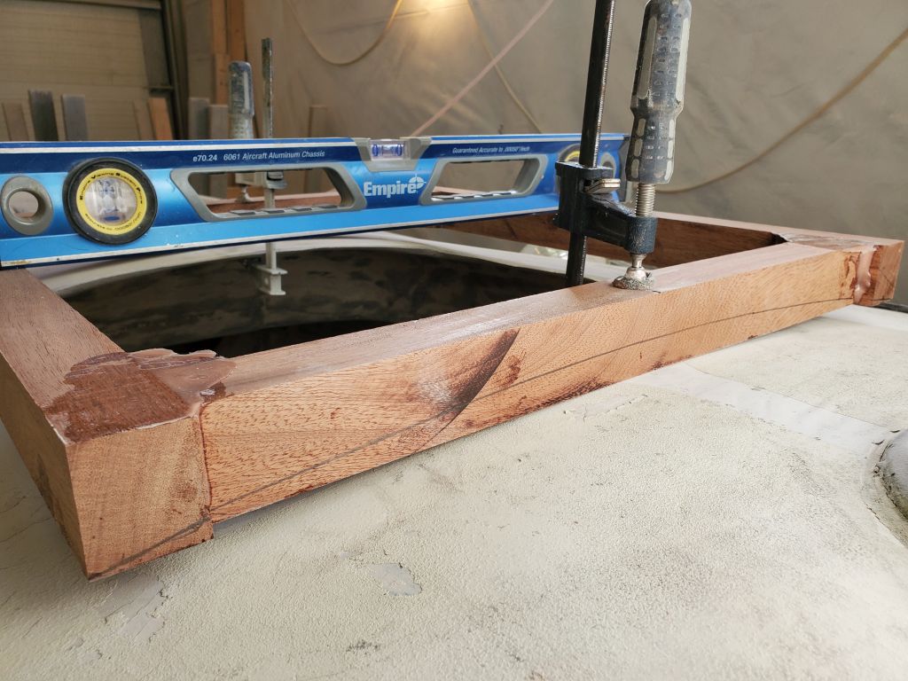
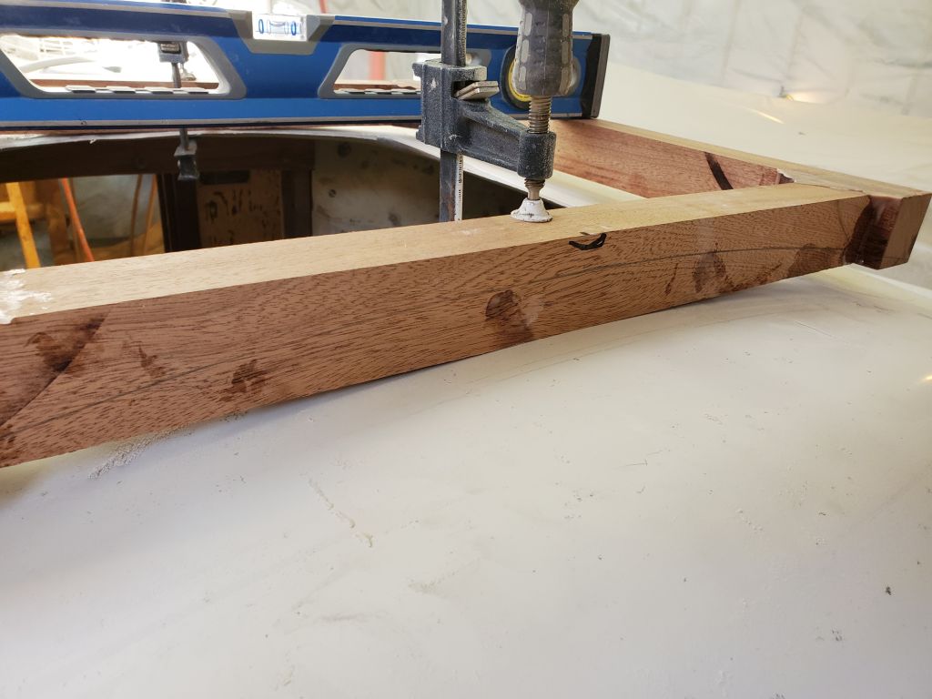
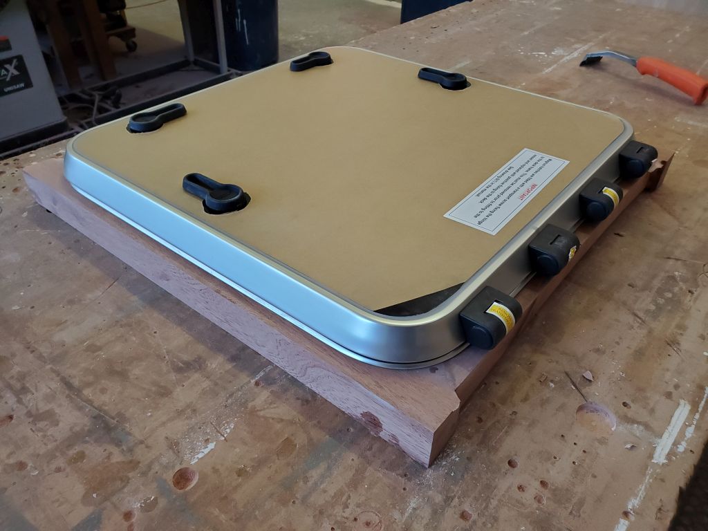
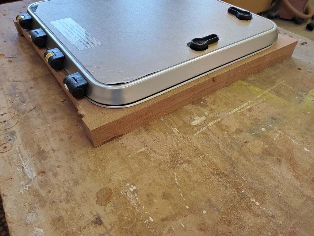
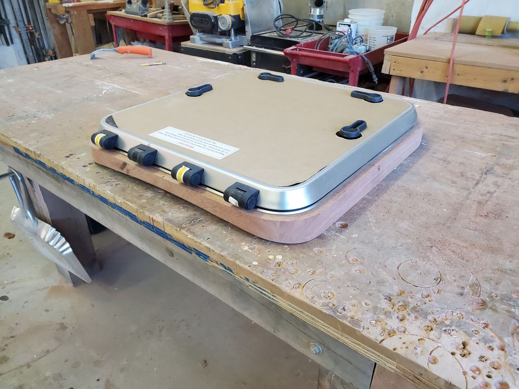
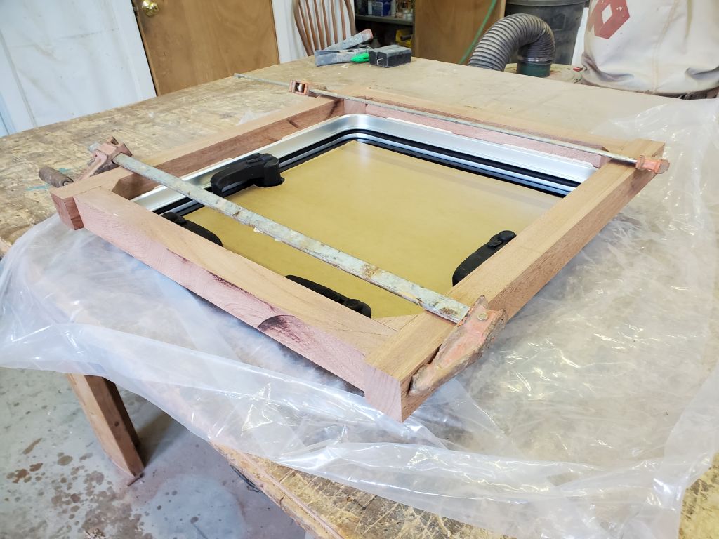
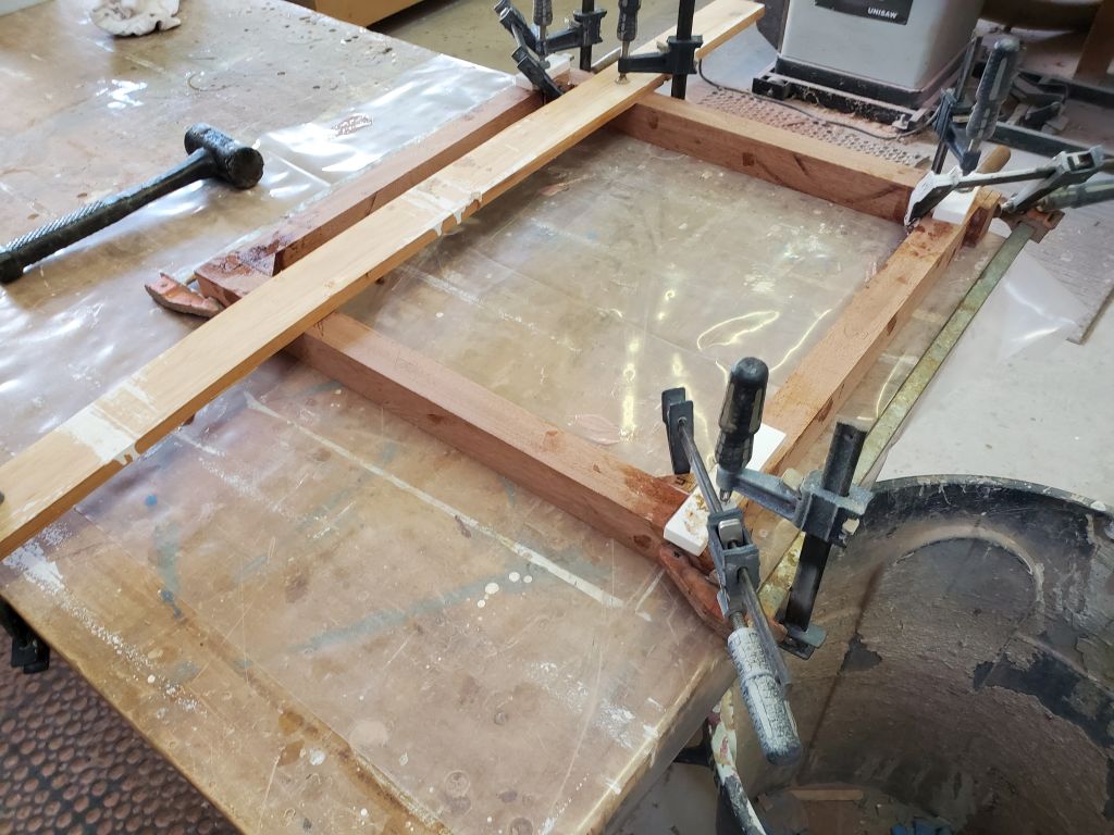
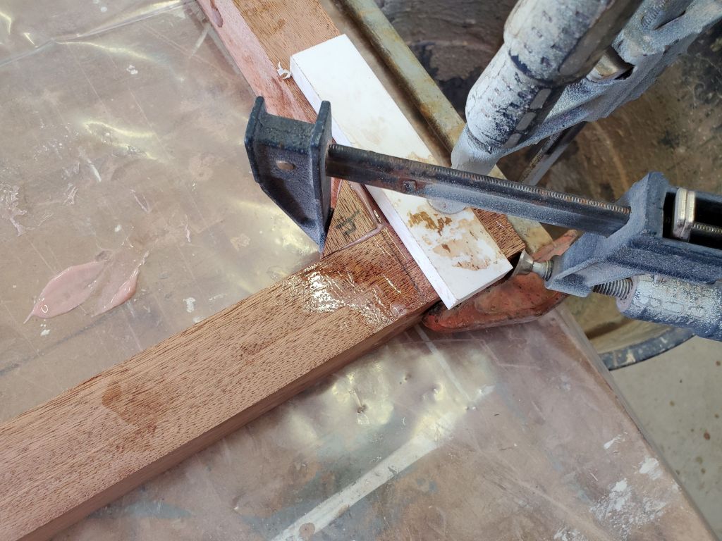
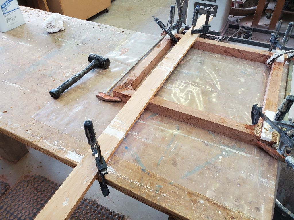
I made reference marks at all four corners to help align the pieces for gluing, then, after solvent-washing the pieces to clean them, glued up the frame with thickened epoxy adhesive. With the frame bottom side up, I clamped it securely to the table to keep things nice and flat. The angled blocks in the corners, in addition to filling in the space, also added gluing area and additional strength to the joints. At three of the four corners, I used light clamping pressure to pull the blocks into the corners; at the fourth corner, where I couldn’t directly clamp the frame to the table, I found that attempts to clamp the corner block tended to pull the joint out of alignment, so I left that block unclamped. I left the frame to cure fully.
Total time billed on this job today: 1.25 hours
0600 Weather Observation: 30°, cloudy, snow shower or two. Forecast for the day: Clearing, 35°.
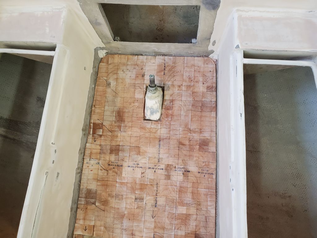
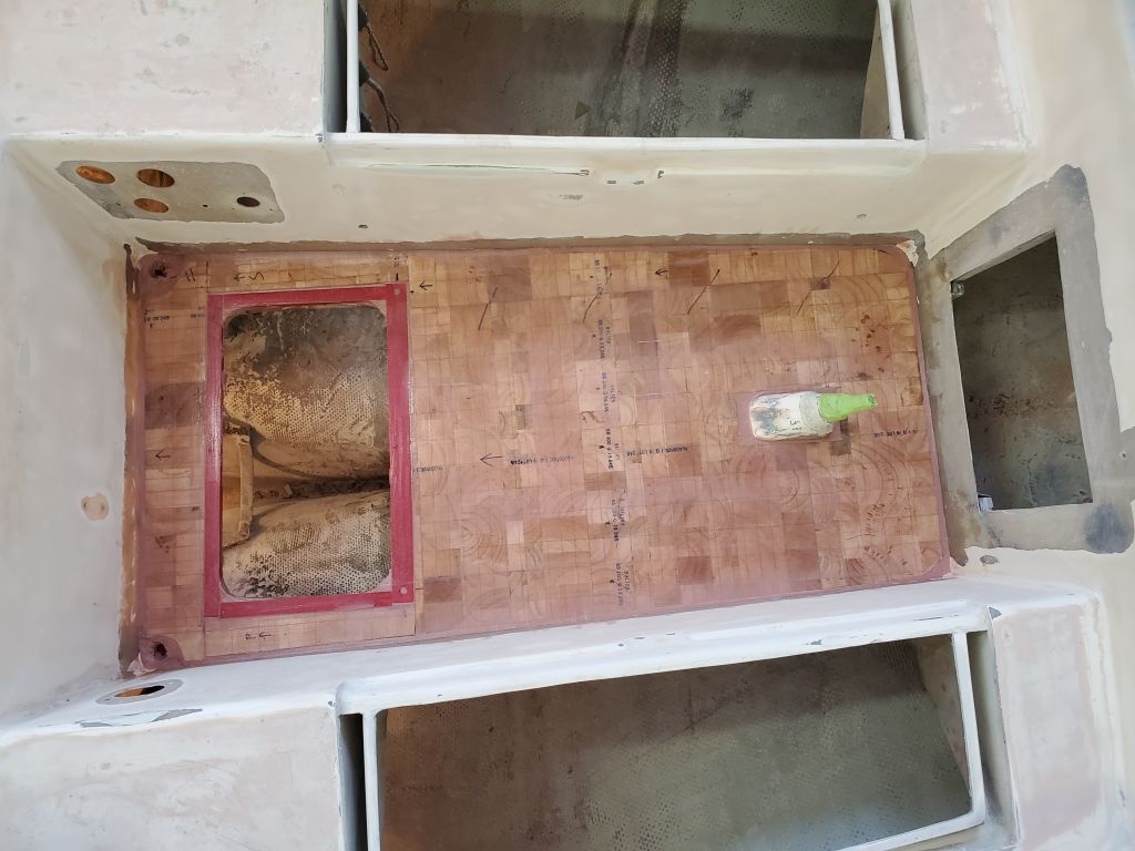
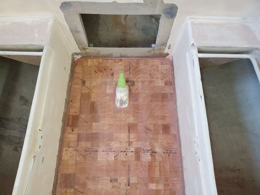
My main focus for the day was the cockpit sole and installing the new top skin laminate. Before I could do that, however, I had various other preparations to complete. Removing the weights and plastic sheeting, I lightly sanded the top of the core to remove any ridges or high spots leftover from the epoxy and installation.
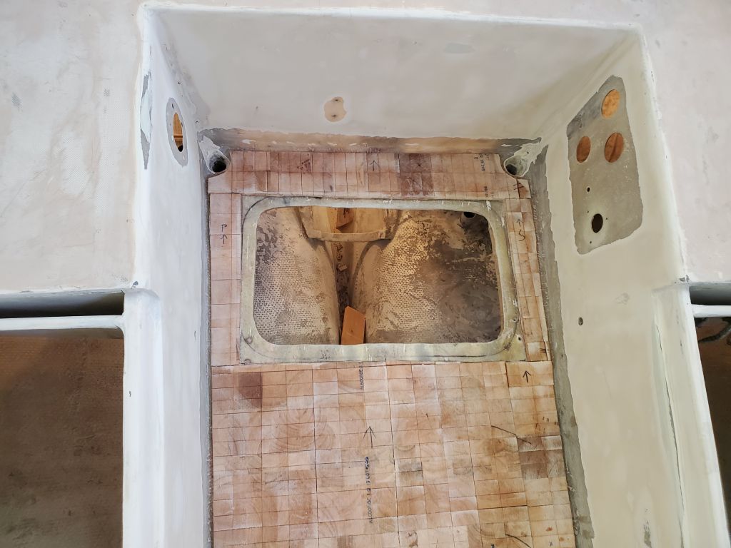
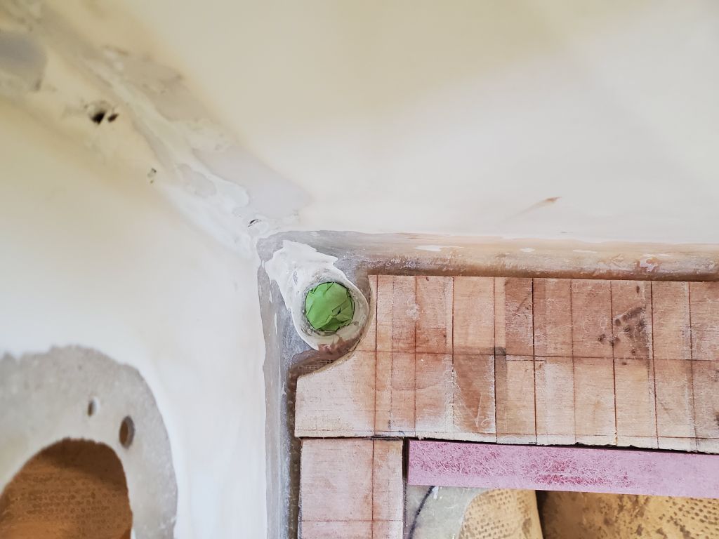
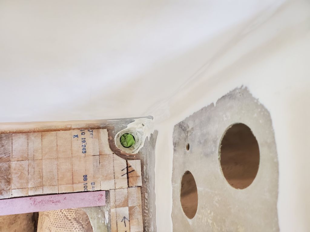
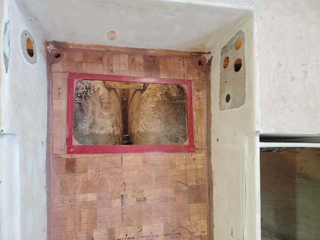
To fill in the area around the hatch opening, I cut pieces of 1/2″ fiberglass laminate to rough size. Then, I glued them in place with epoxy adhesive, using more of the thickened epoxy to fill in small gaps around the hatch and, eventually, at the edges of the new core where it met the cockpit sides. Since the original sole had a fairly wide radius at this corner, and the cockpit well featured slightly angled sides, the top edge of the core didn’t touch the sides, so I had to fill these gaps with epoxy now. After filling the cockpit drain tubes with some tape just below deck level, I filled the voids I’d left in the core around the scuppers with more thickened epoxy; I’d redrill and shape these openings more later in the reconstruction process. Finally, I filled all the kerfs in the core with thickened epoxy and troweled over the whole area, which served not only to fill and smooth, but also to wet out and prepare for the top skin.
While allowing the epoxy to tack up just a bit, I prepared my station to wet out the top skins, then, when appropriate, I installed two layers of 1708 fabric over the new core, bringing the material slightly up the edges of the cockpit well as designed. I brought the laminate right over the scuppers for now and would redrill the holes later. During fabric cutting earlier, I’d cut out the bulk of the opening for the new deck hatch in the first layer of cloth, but, belatedly growing wiser, I’d left the cloth whole for the second lager but didn’t wet out the whole area. This did make the cloth more stable during installation. Much later in the day–so late I almost forgot and worried I’d waited too long–I used a sharp knife to trim the fiberglass at the edges of the hatch opening, removing the excess from within. As it happened, the epoxy had cured just the right amount to allow for a clean cut. This hatch opening would require minor recutting to the pattern later.
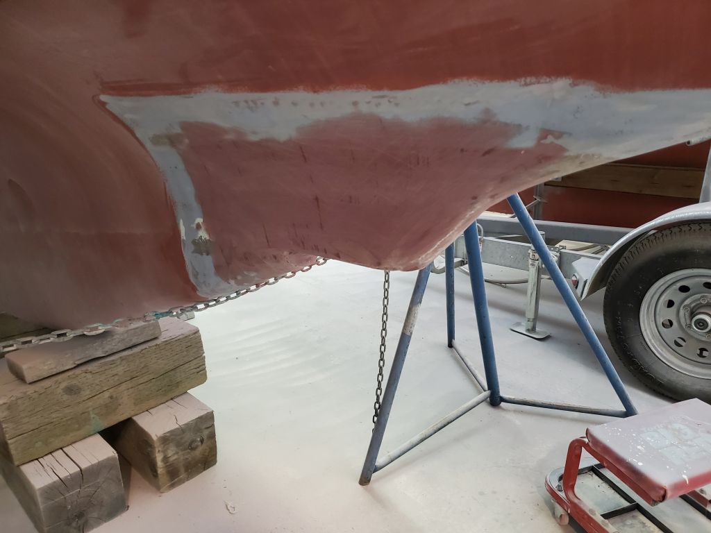
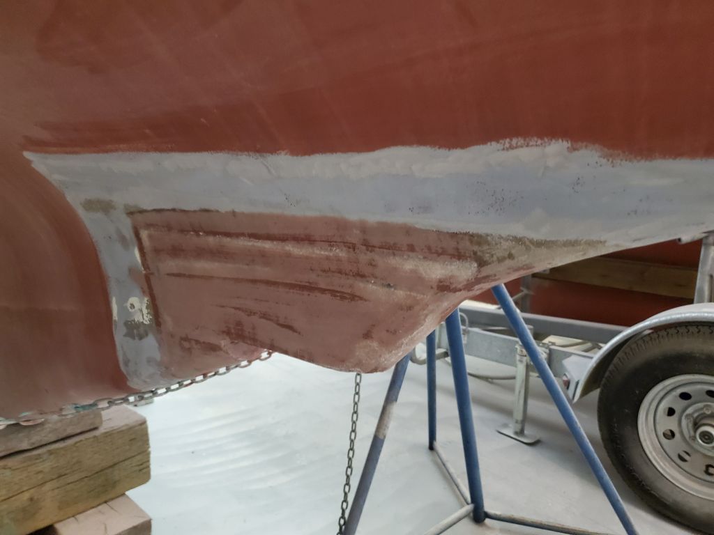
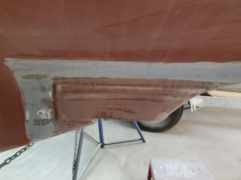
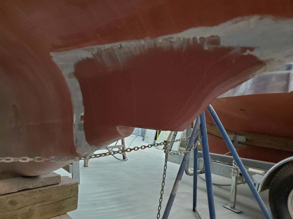
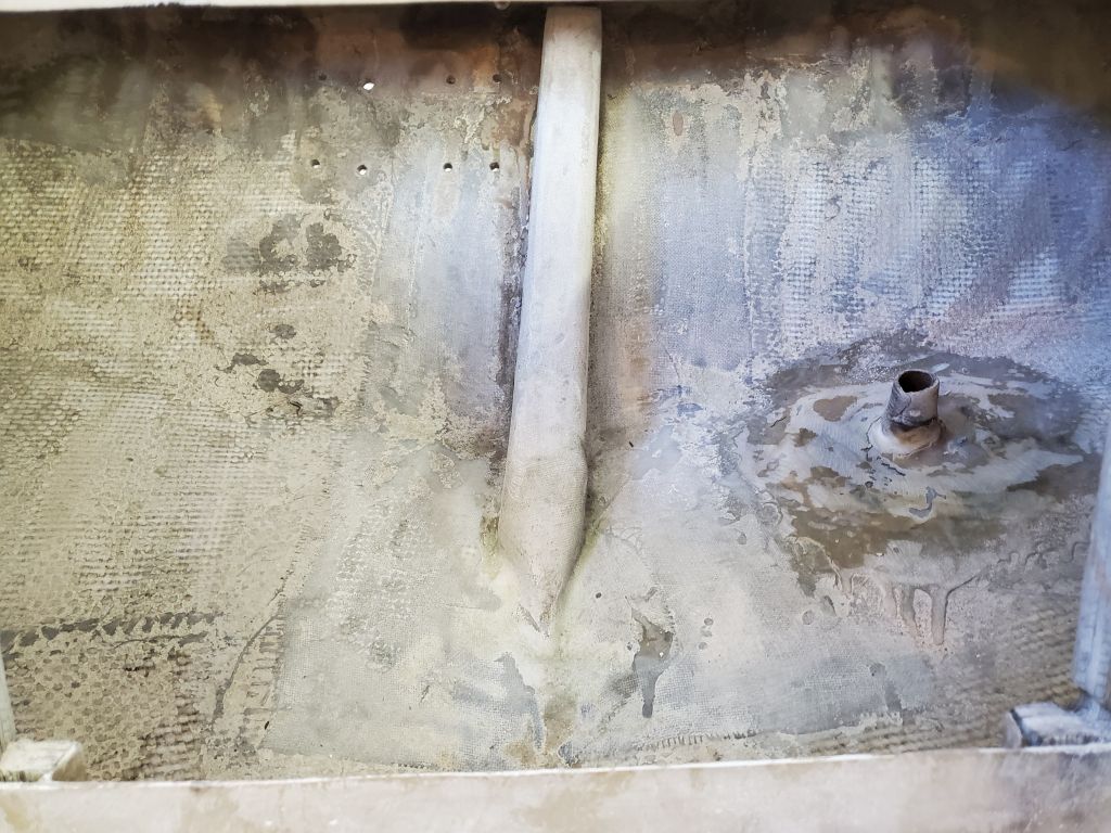
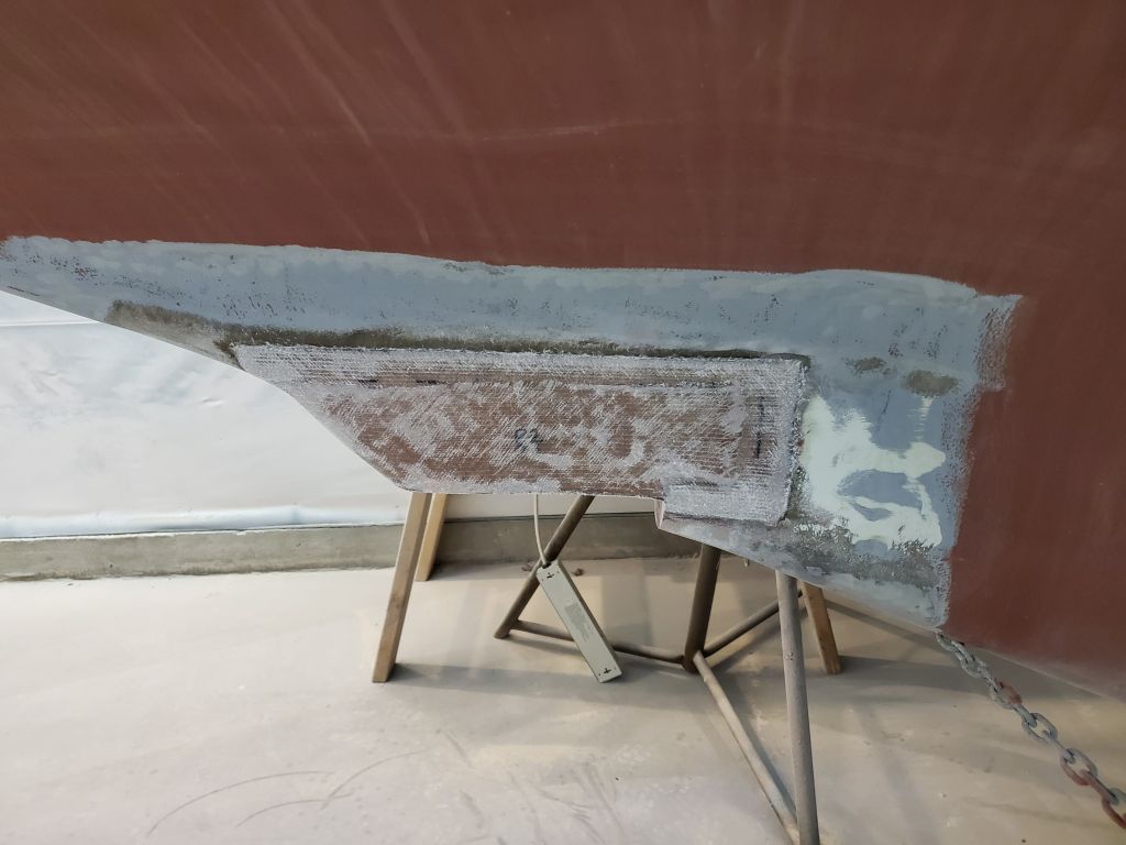
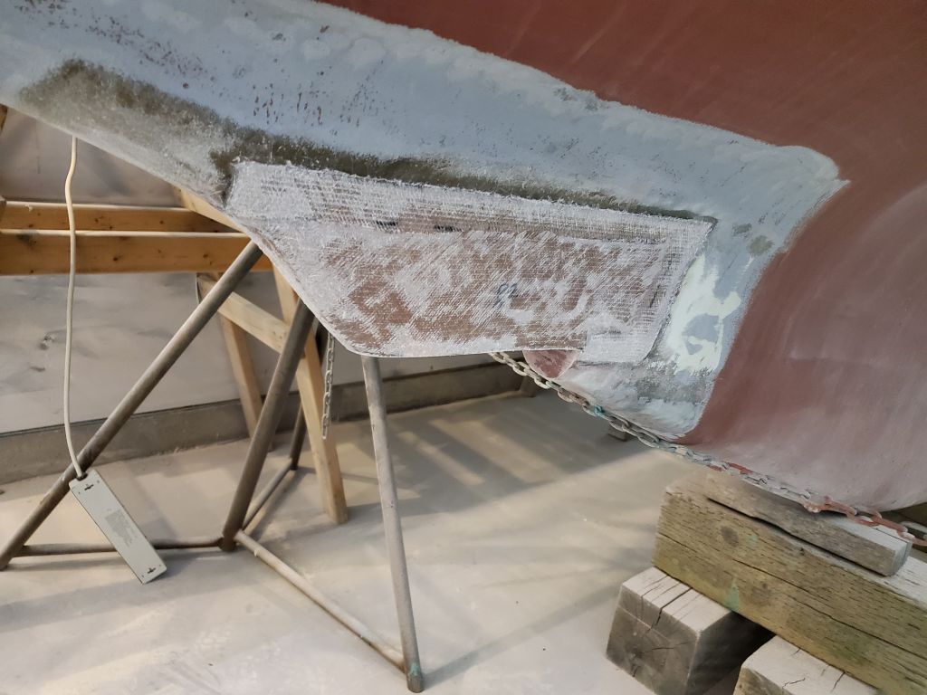
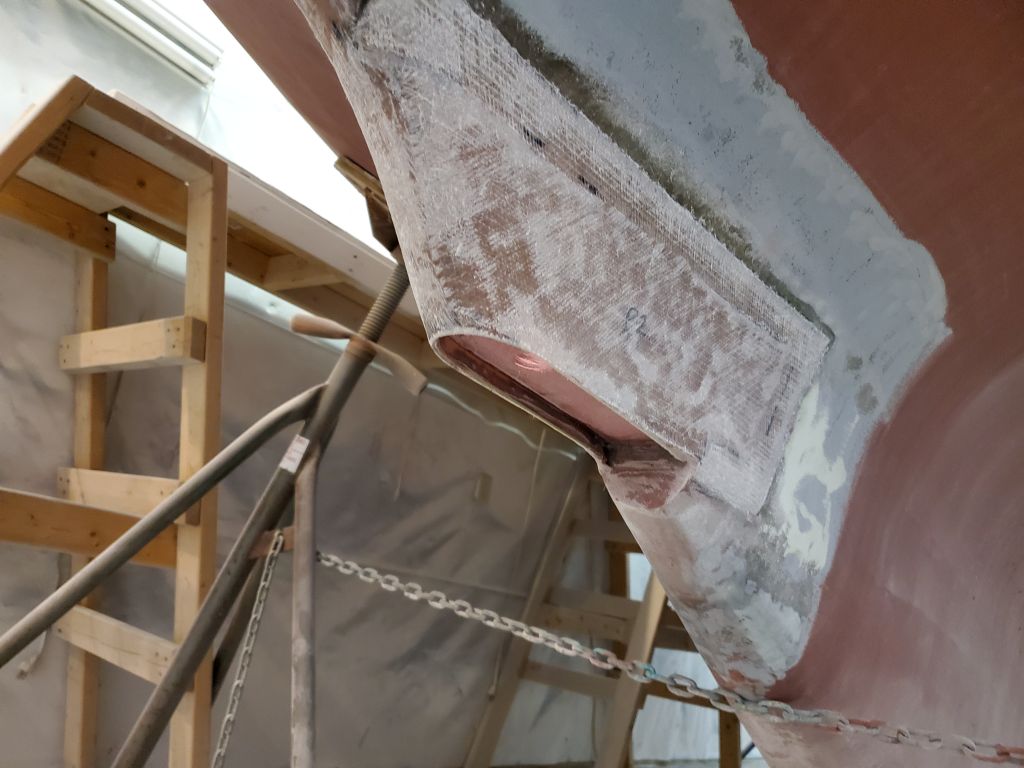
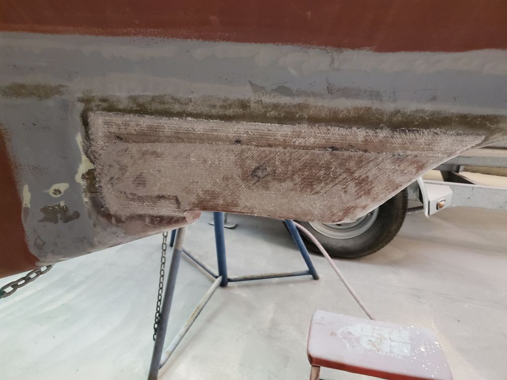
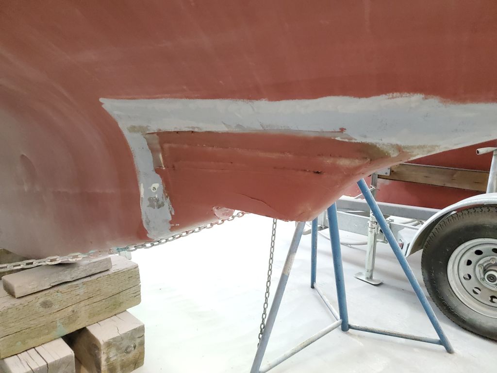
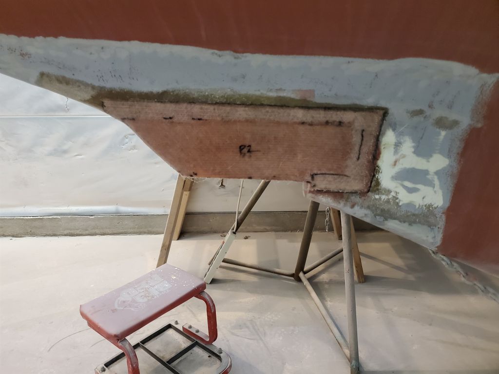
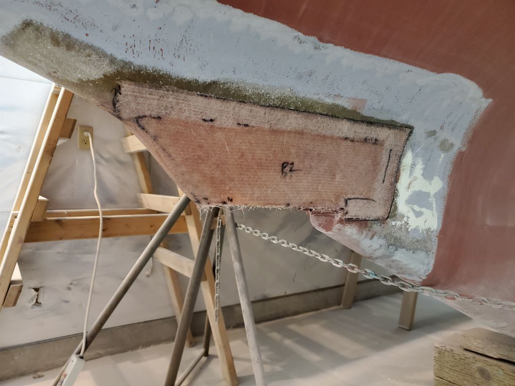
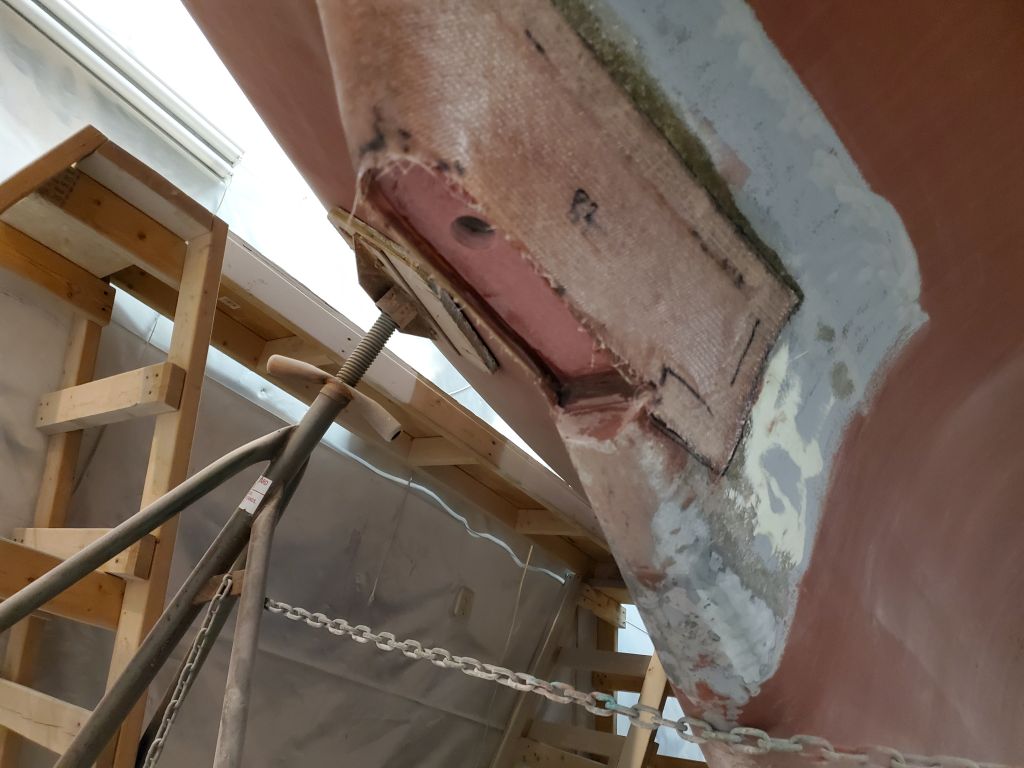
With the day’s main event behind me, I turned to some additional tasks, starting with the transducer housing fairing and ongoing patchwork on the old engine intake through hulls. These works required light sanding, which nearly completed the work on the engine intake–save for a small low area that required a bit of filler-and prepared the transducer for the next step, which was to install structural fiberglass over the whole area, to strengthen and complete the housing, and to tie it all in with the adjacent hull.
I patterned and cut two layers of fiberglass for the transducer, staggering the layers and overlapping the seams between the two. Each piece required a custom cut at the forward edge to wrap around the curved portion of the housing. Afterwards, I installed the new fiberglass in epoxy resin. All that remained now was some final fairing once the new fiberglass had cured.
I’d received a piece of 8/4 Sipo (mahogany) for the new forward hatch frame (and other trims as needed), and to finish up the day’s work I planed the rough stock till it was smooth on both sides, ending up with about 1-7/8″ thickness thereafter. Then, I straightened one of the irregular edges to prepare the stock for final dimensioning and the construction of the hatch frame in the near future.
Total time billed on this job today: 7.25 hours
0600 Weather Observation: 19°, clear. Forecast for the day: Increasing clouds, rain or snow in the afternoon, 38°.