Monday
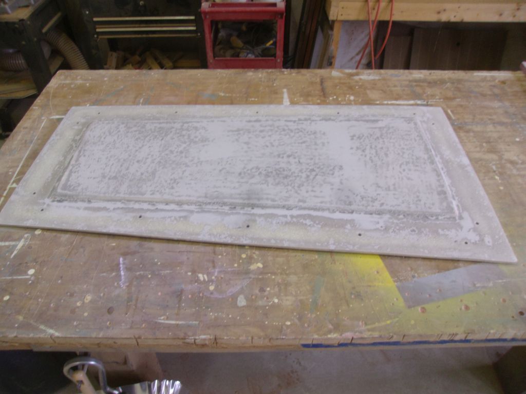
Preparing for the engine hatch modification to allow the hatch to clear the engine properly, I sanded the underside of the existing hatch, removing the factory finish from the edges to expose bare laminate, and scuffing the whole surface to prepare it for eventual paint later. I also sanded the factory surface of the prefabricated fiberglass sheet I’d purchased to build the 1-1/2″ tall lip around the edge.

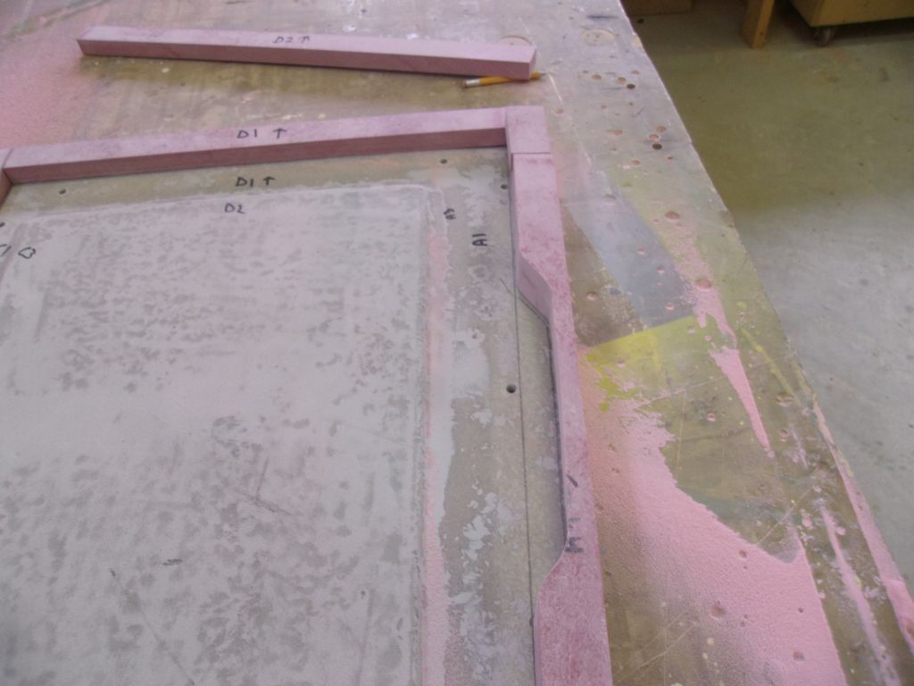
Although 1-1/2″ square prefab fiberglass was available, it came in awkwardly long lengths, and was more expensive in the end than the sheet of 3/4″ that I decided on, so my first step was to rip enough strips of fiberglass to build two layers (for the total 1-1/2″ height required) around the perimeter of the hatch. The final width of the strips ended up at 1-1/4″, which kept them outside of the engine hatch fixing bolt holes.
With enough strips prepared, I laid out and cut the two layers required to wrap the hatch perimeter, staggering the joints between the two layers.
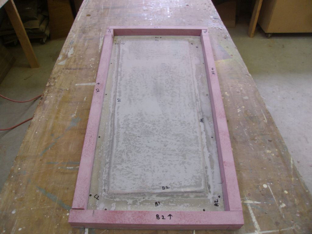
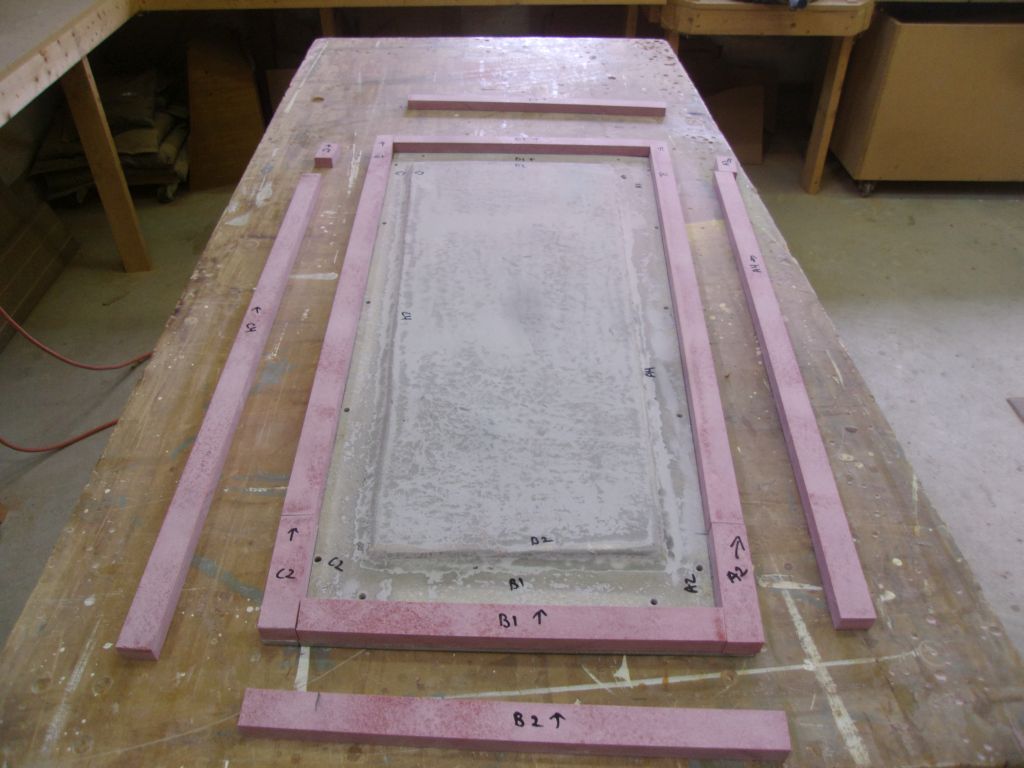
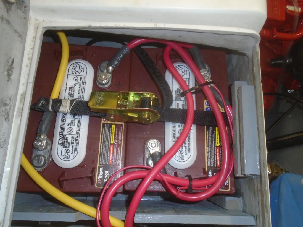
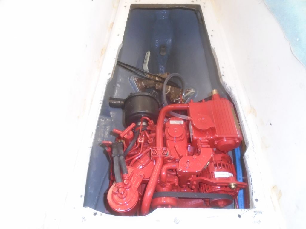
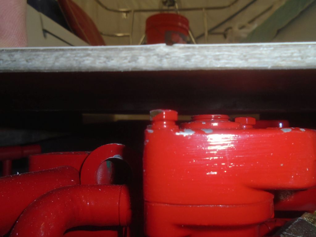
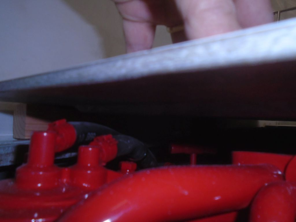
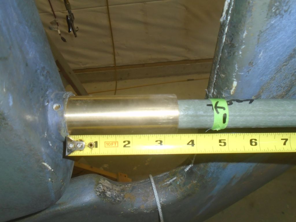
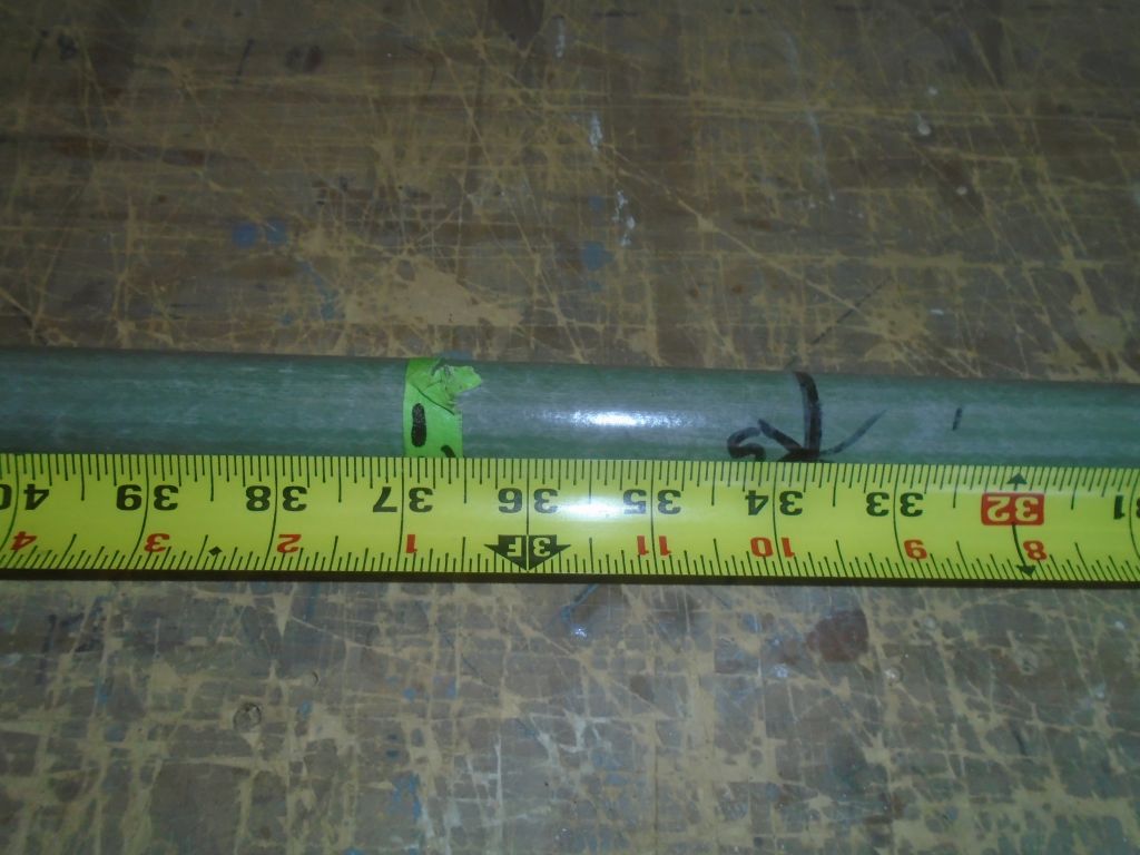
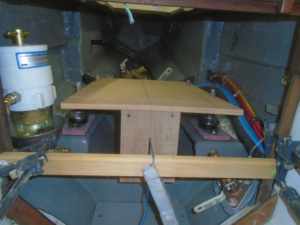
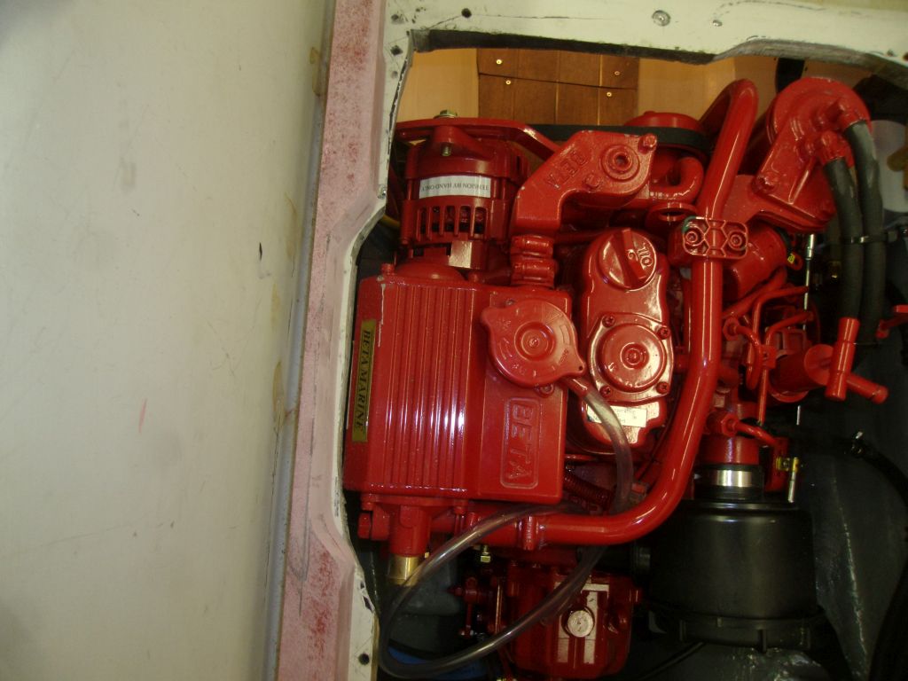
To clear the heat exchanger on the port side, which stuck out into the edge of the opening quite a bit, I laid out the two port strips as needed and marked and cut out a section in way of the heat exchanger. I also double-checked the height of the new edge to ensure that it would properly clear the highest point on the engine; with the 1/4″ – 3/8″ downward projection of the engine hatch core, the height was right where it needed to be.

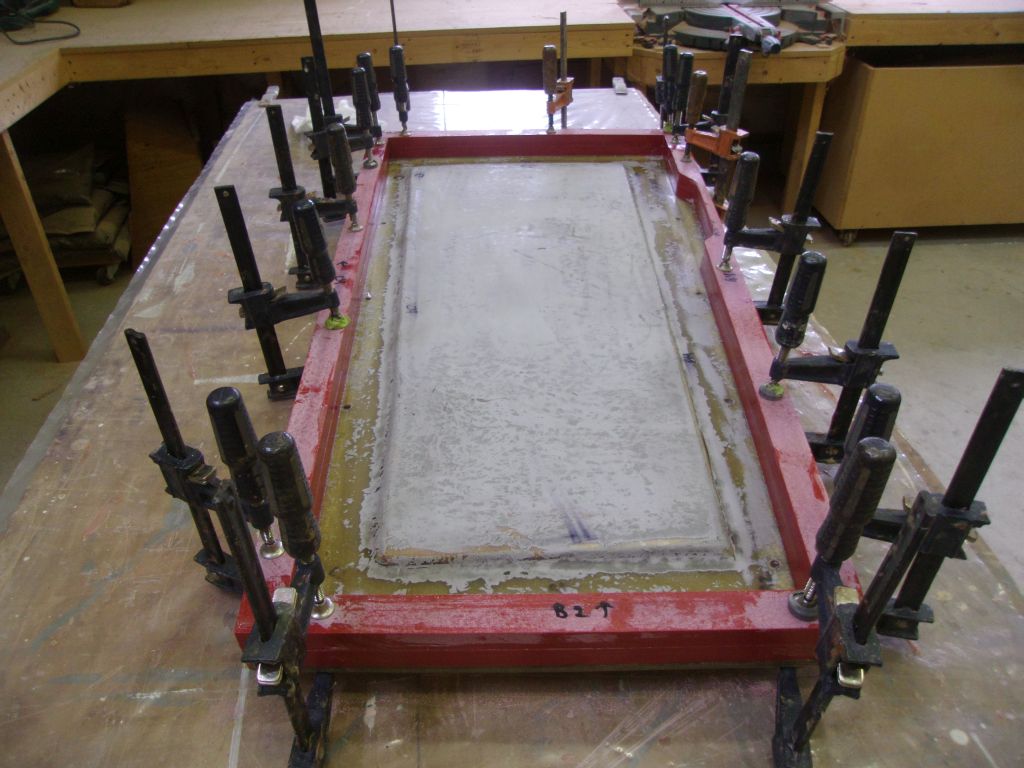
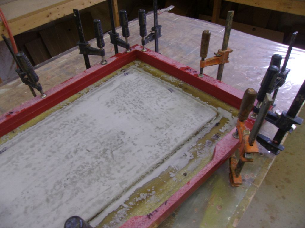
It would be much too difficult to laminate both layers to the hatch at once, so I started with one layer, glued to the hatch with epoxy adhesive and clamped into place.
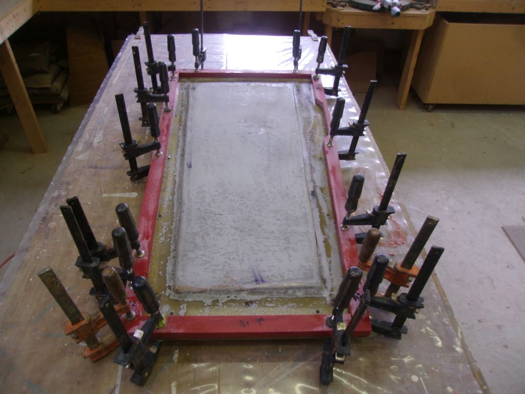
Late in the day, the first round of epoxy had cured enough to allow me to remove the clamps and install the second layer of 3/4″ edge banding on top of the first.
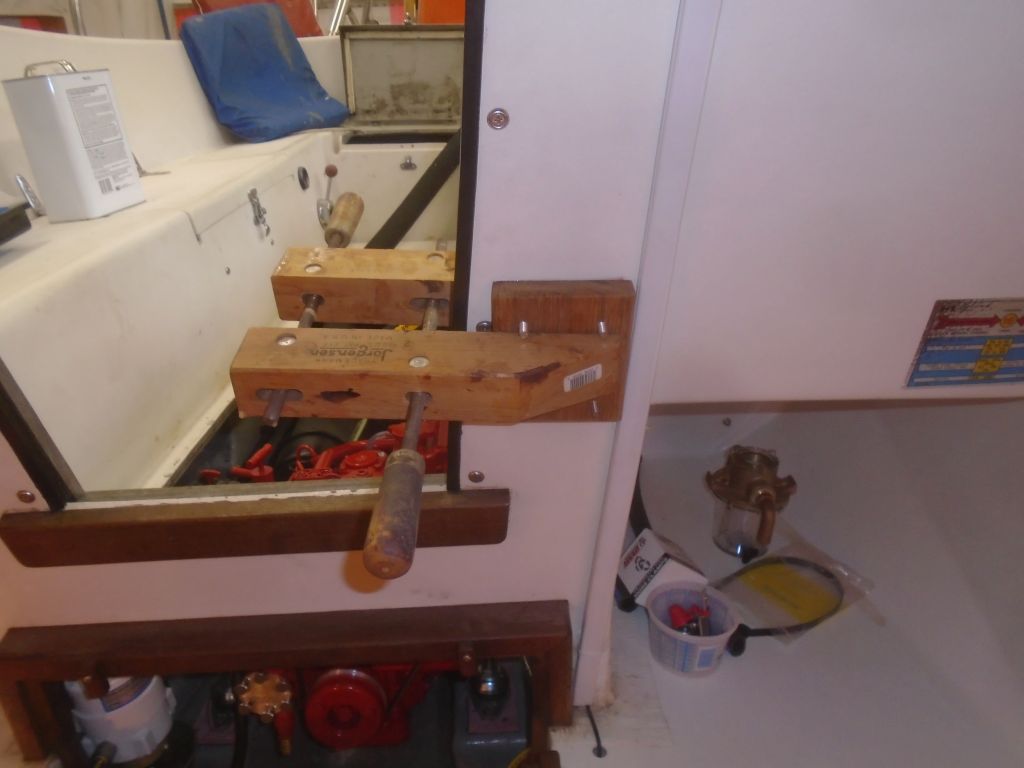
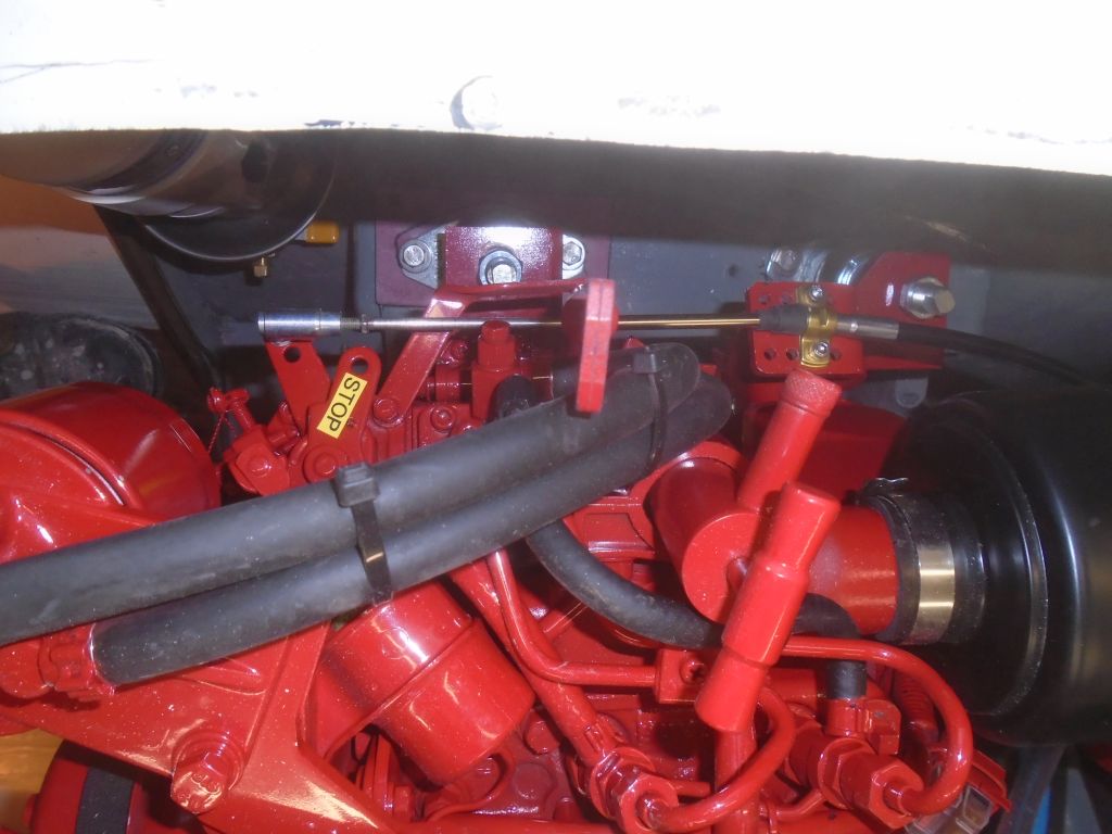
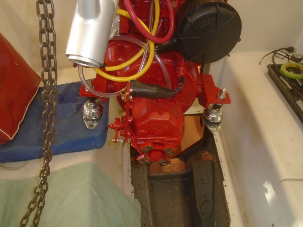
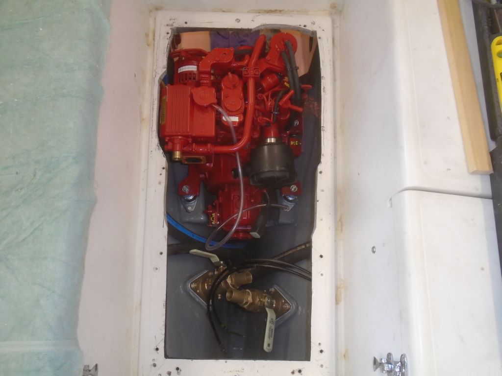
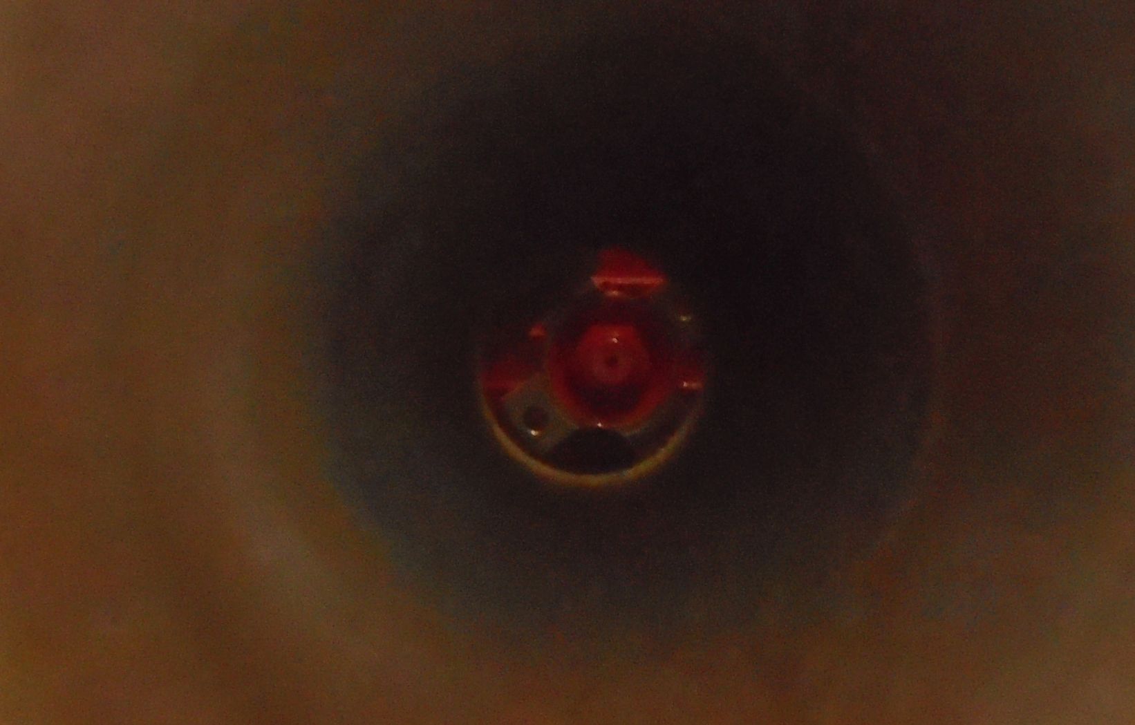
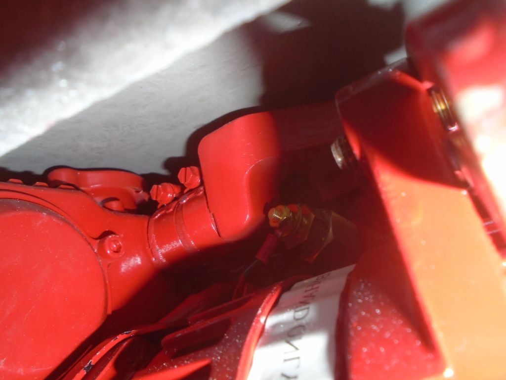
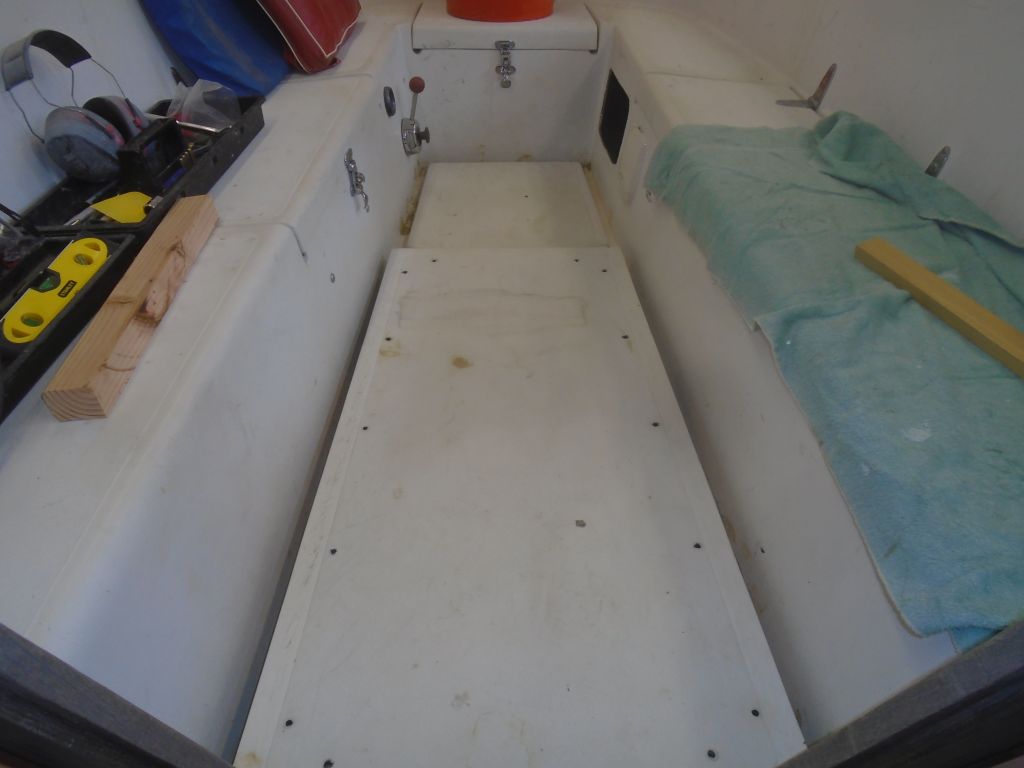
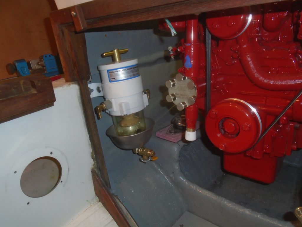
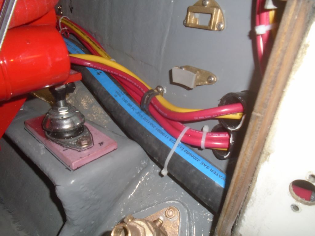
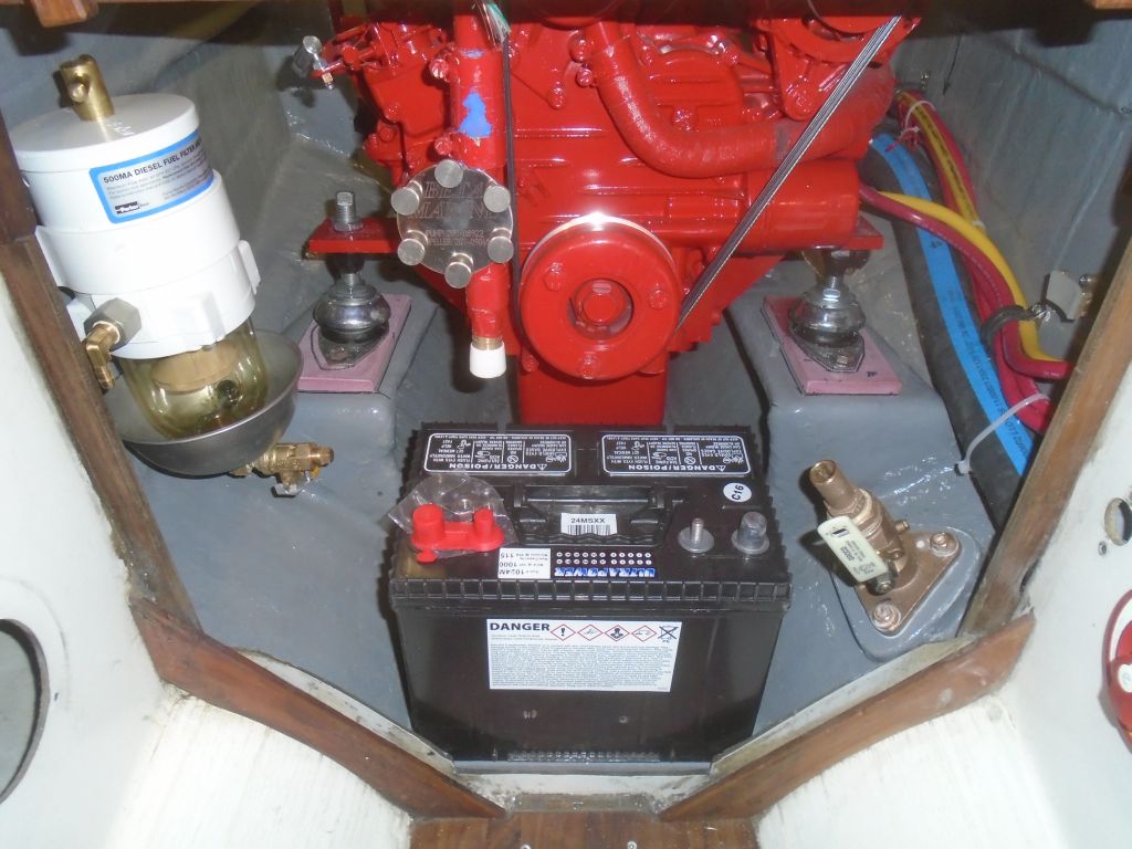
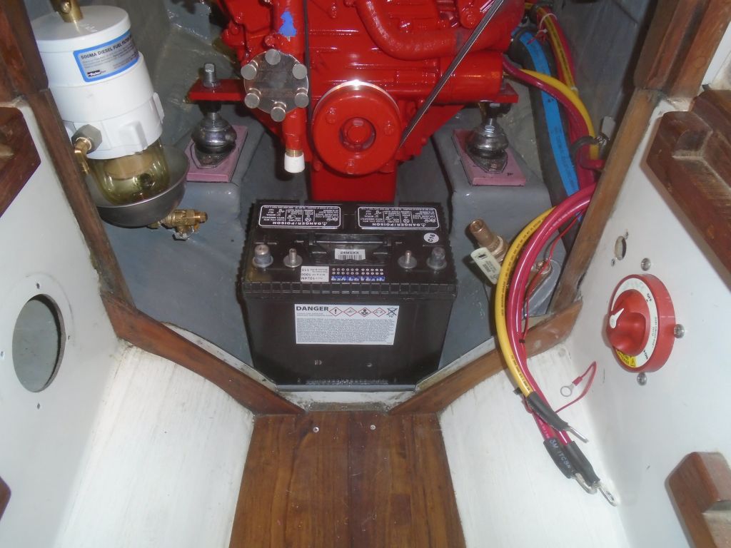
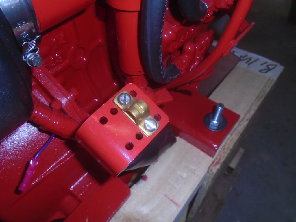
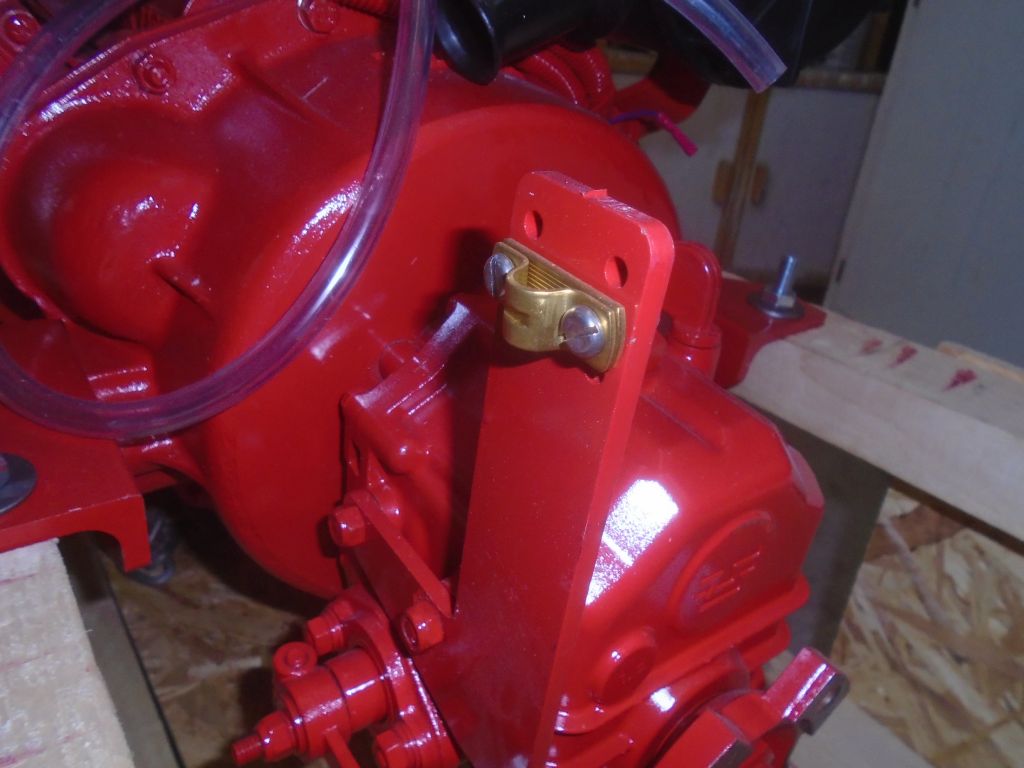
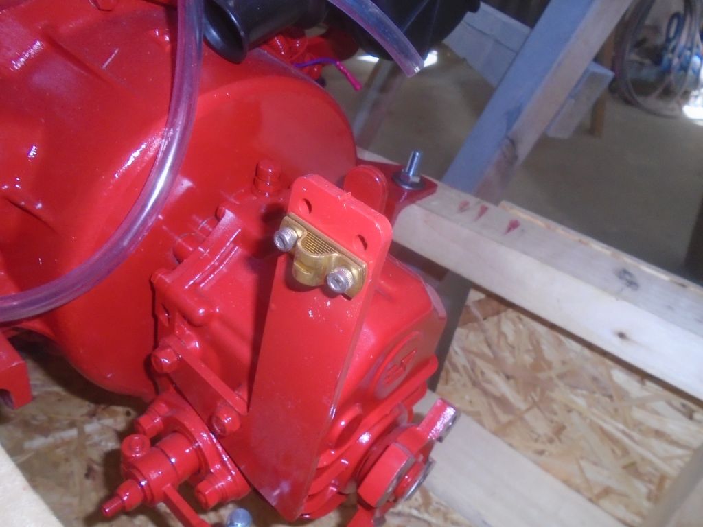
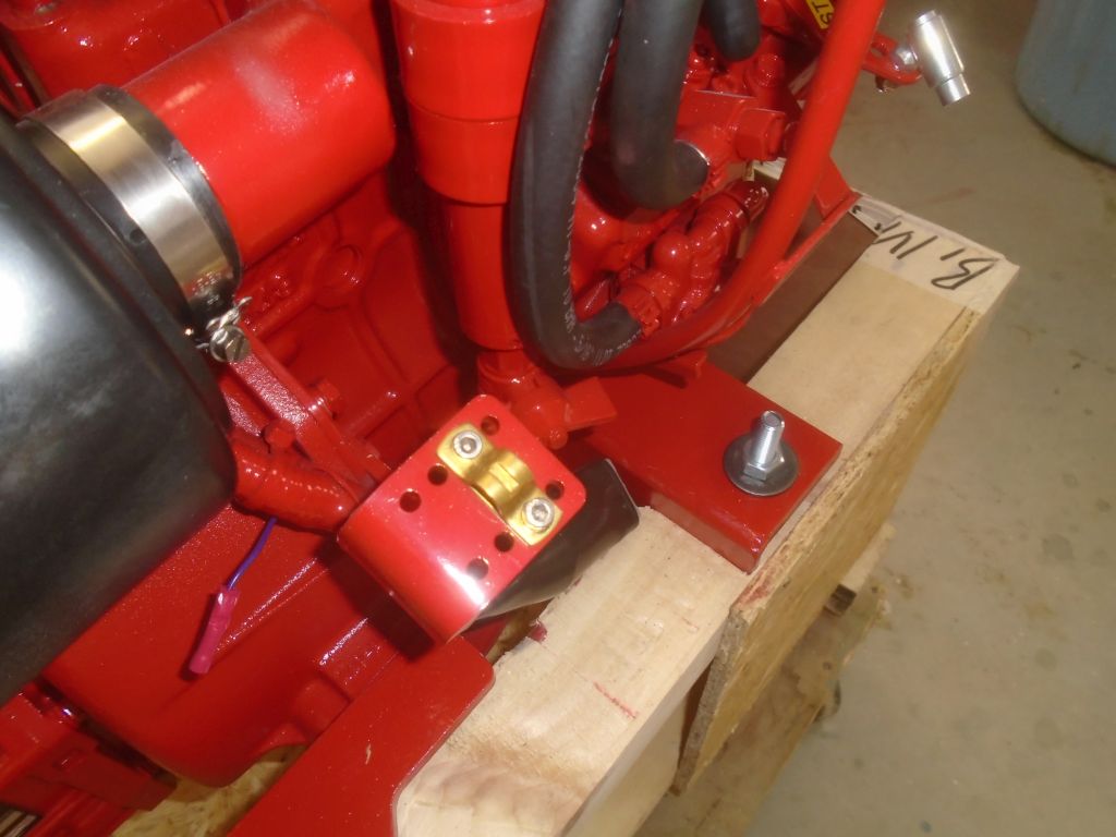
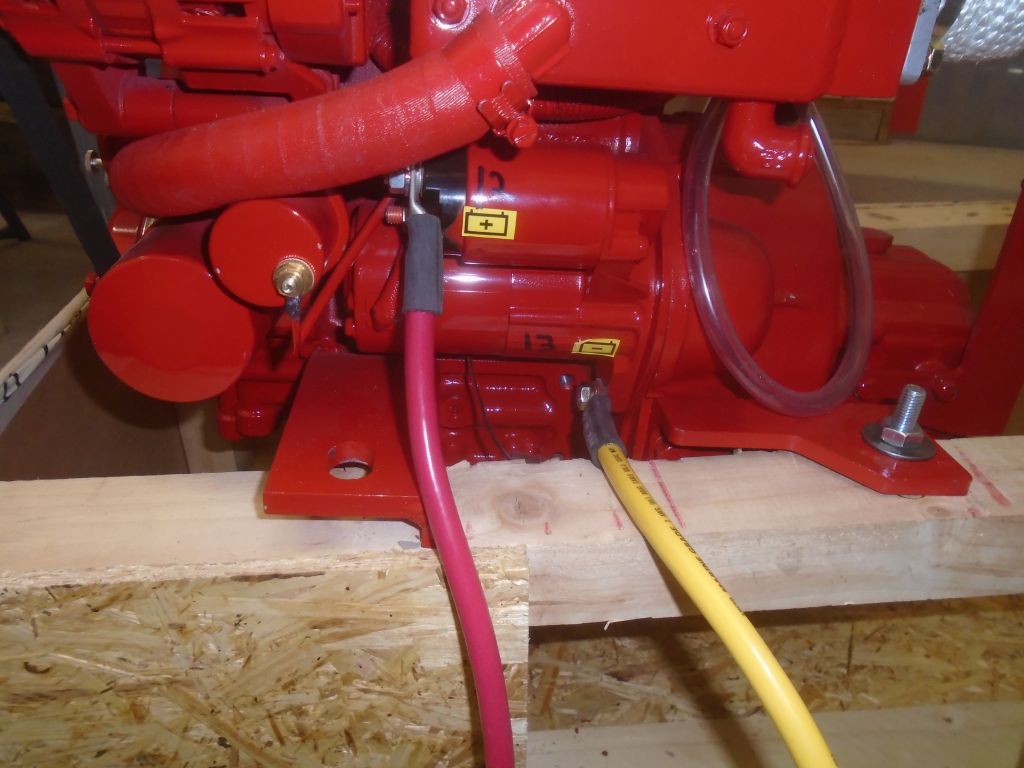
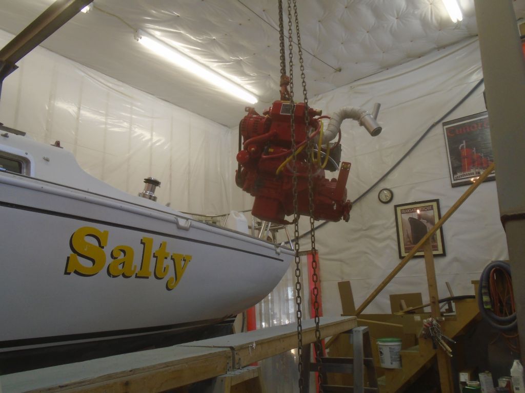
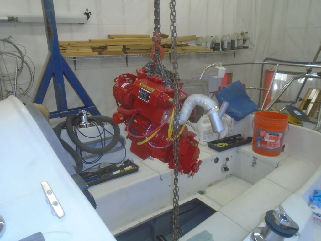
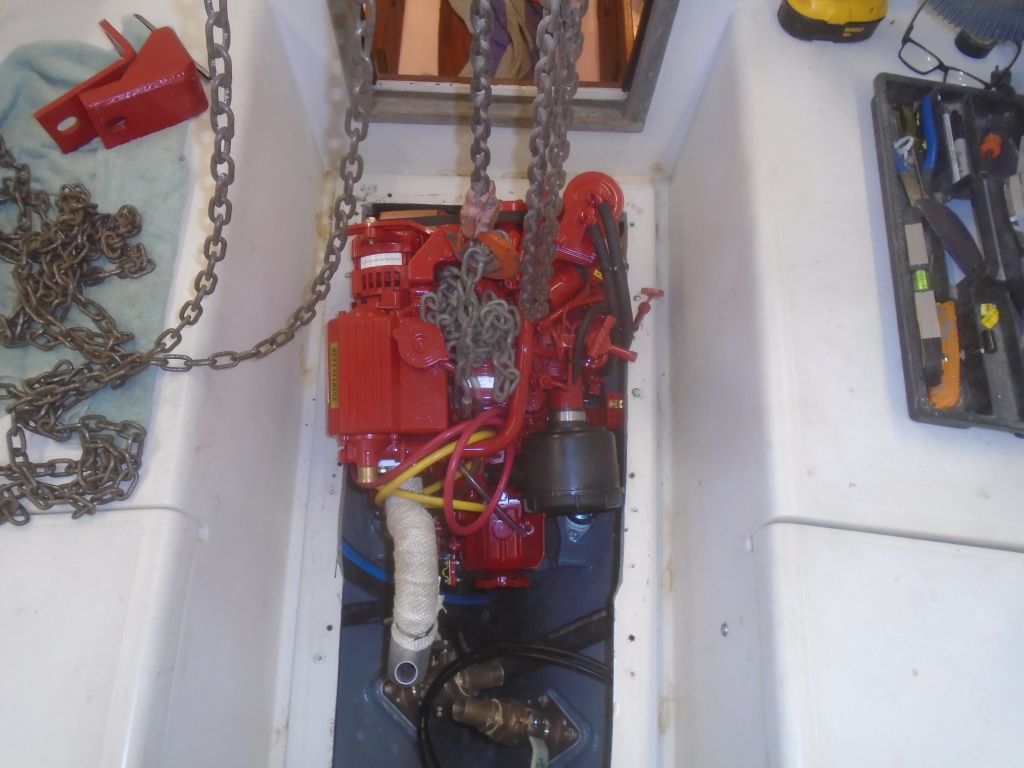
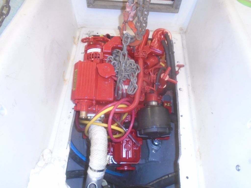
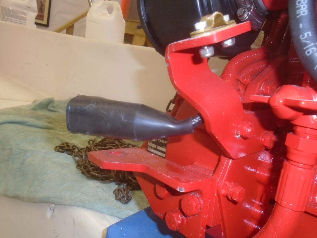
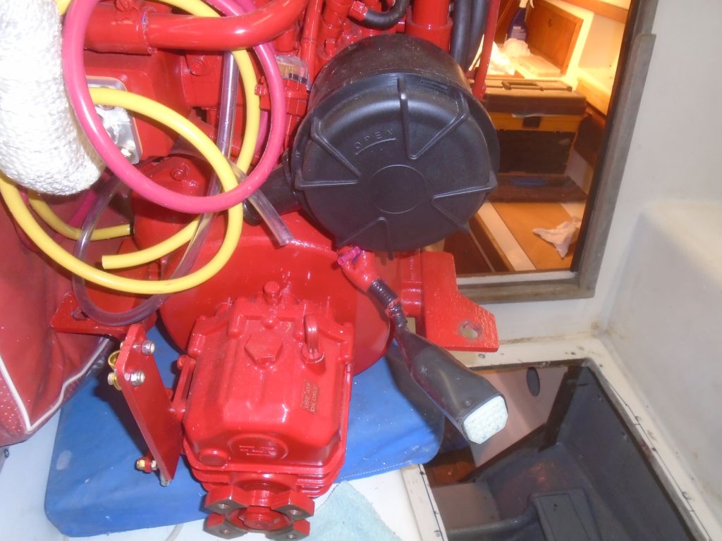
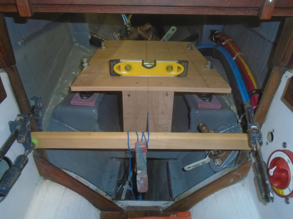
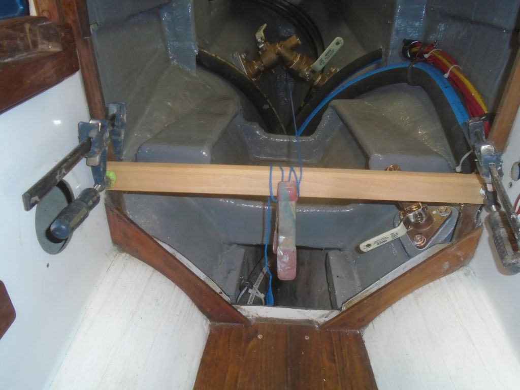
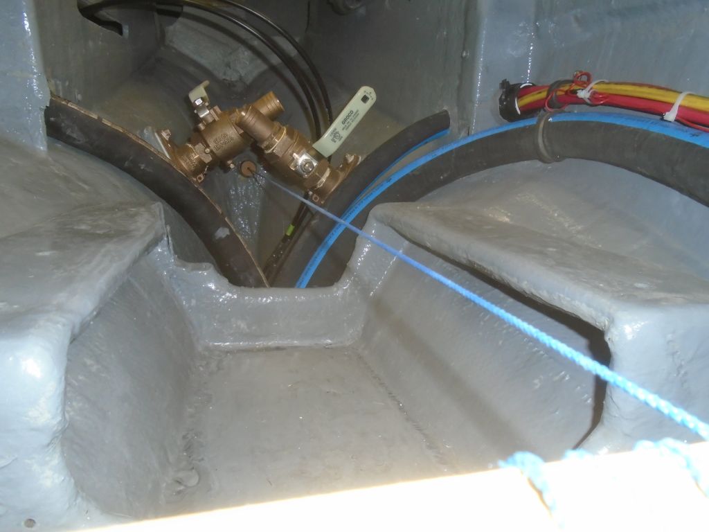
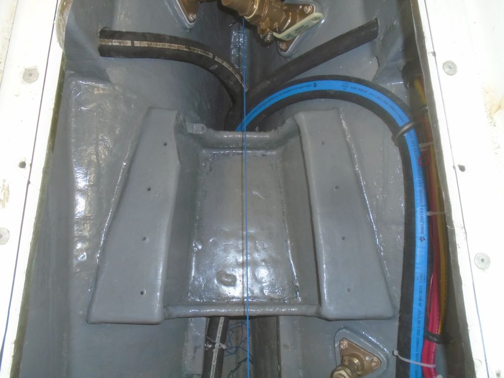
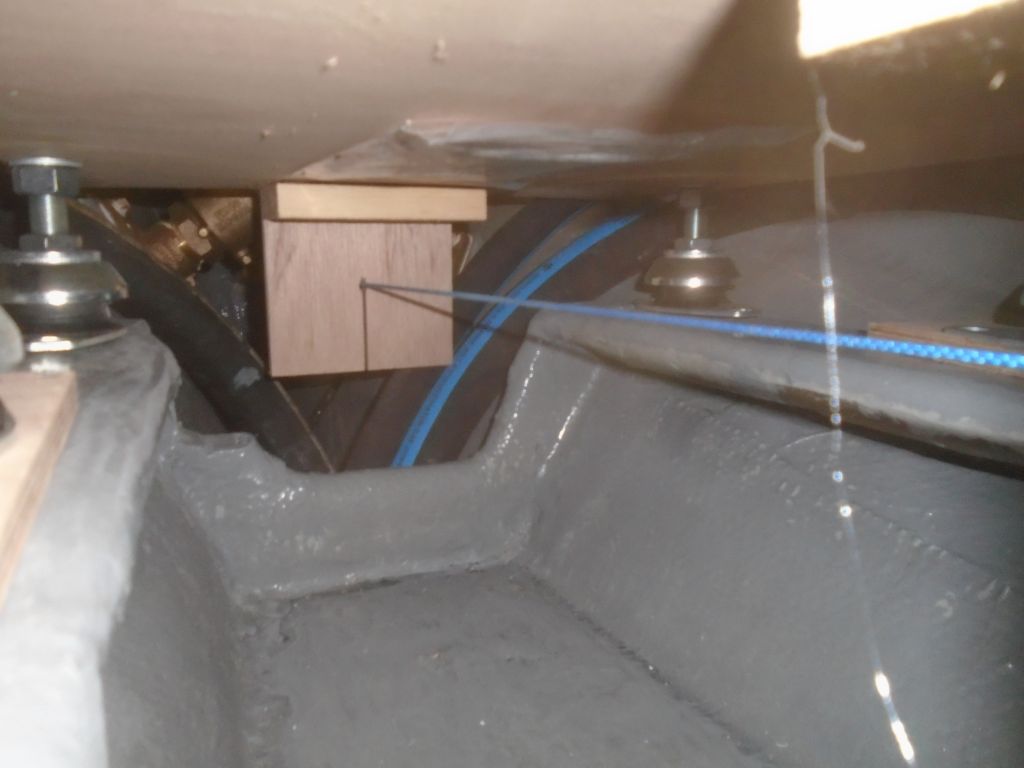
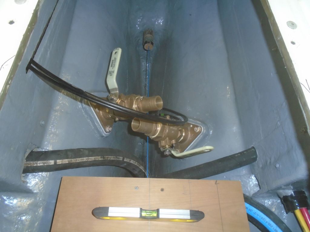
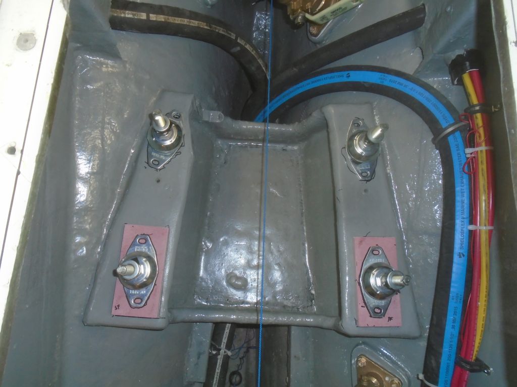
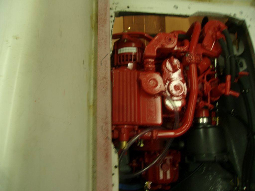
When the engine was shifted into reverse, the lever on the transmission actually contacted the U-shaped aft edge of the engine foundation. This is the sort of thing that’s hard to know might happen in advance, but the other side of the foundation had been similarly cut to accommodate the lever on the old engine (which had been to starboard, not port), so I suppose I should have known. With the engine still loosely secured on its mounts, the lever could push down and actually move the engine over a little, but that wouldn’t happen once the engine was properly secured, and in any event wasn’t an acceptable condition going forward.
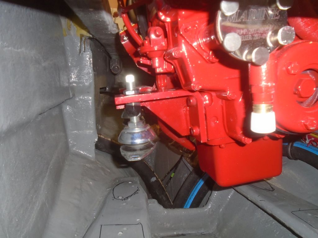
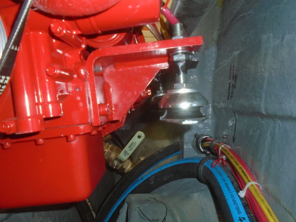
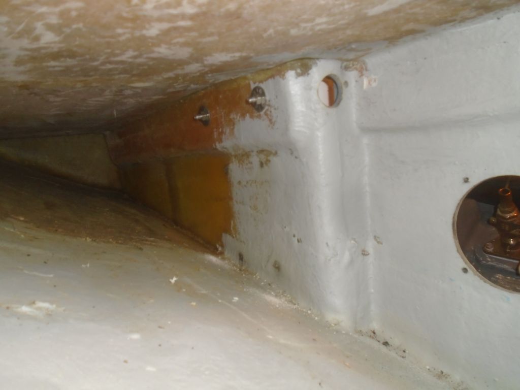
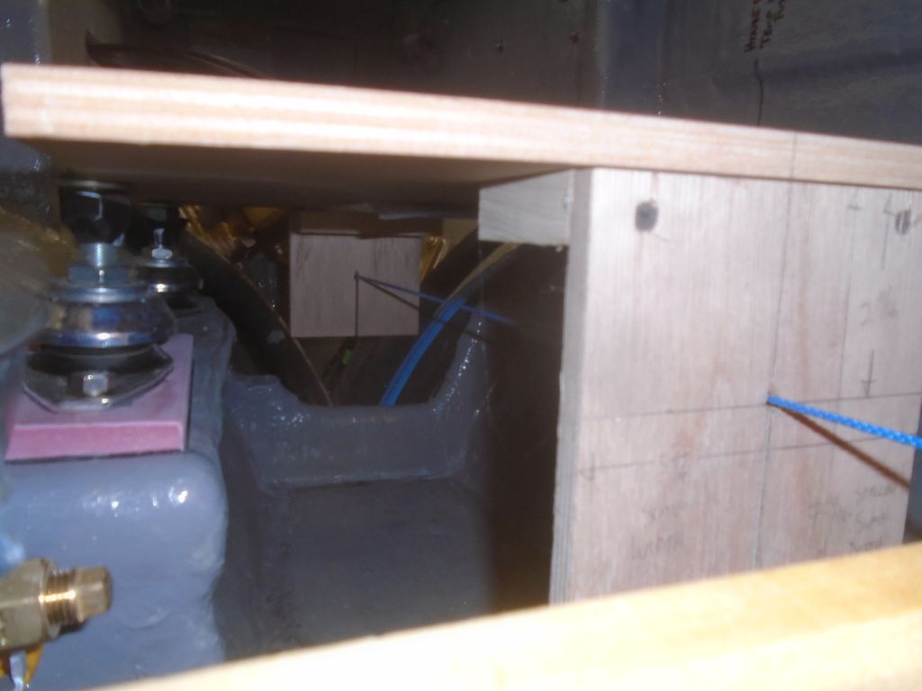
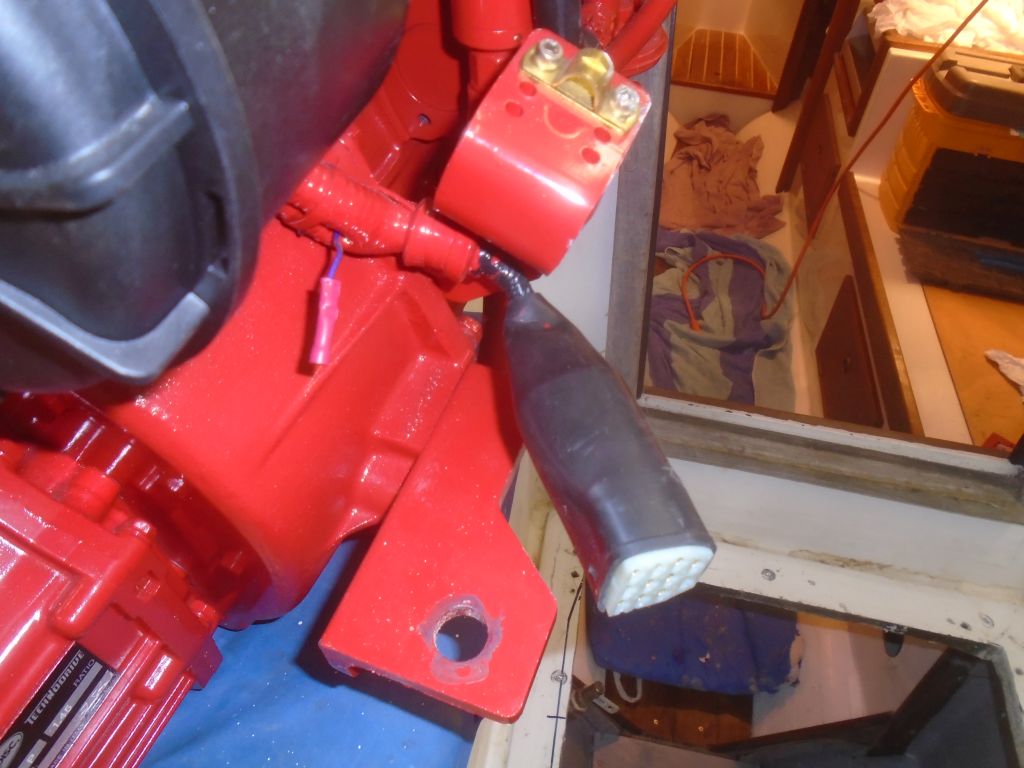
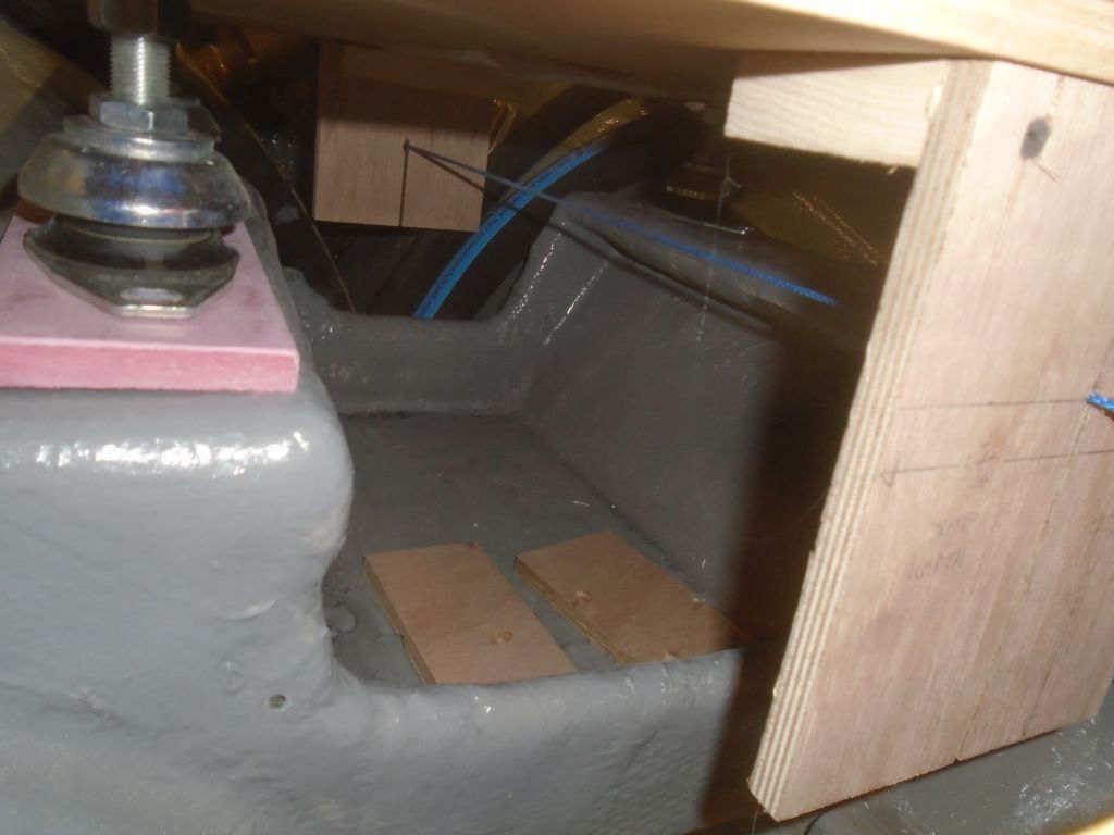
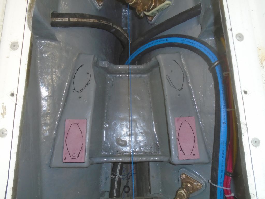
With a saw, I cut away some of the foundation to allow the transmission lever the clearance it needed for reverse. Though the cut was small, access was a challenge, and there was no good way to arrange myself and the saw down in the depths, but it had to be done whether it was easy or hard. Of greatest concern was the requirement to avoid damaging anything else in the tight confines.
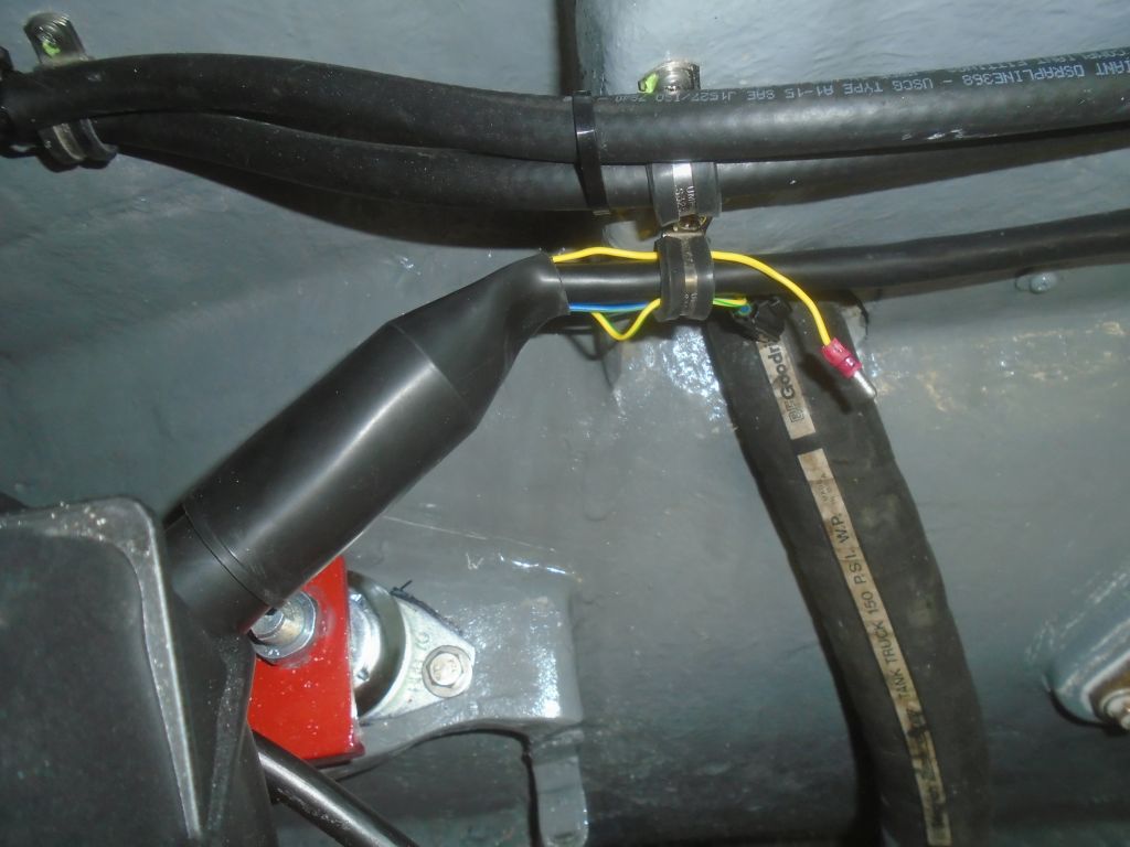
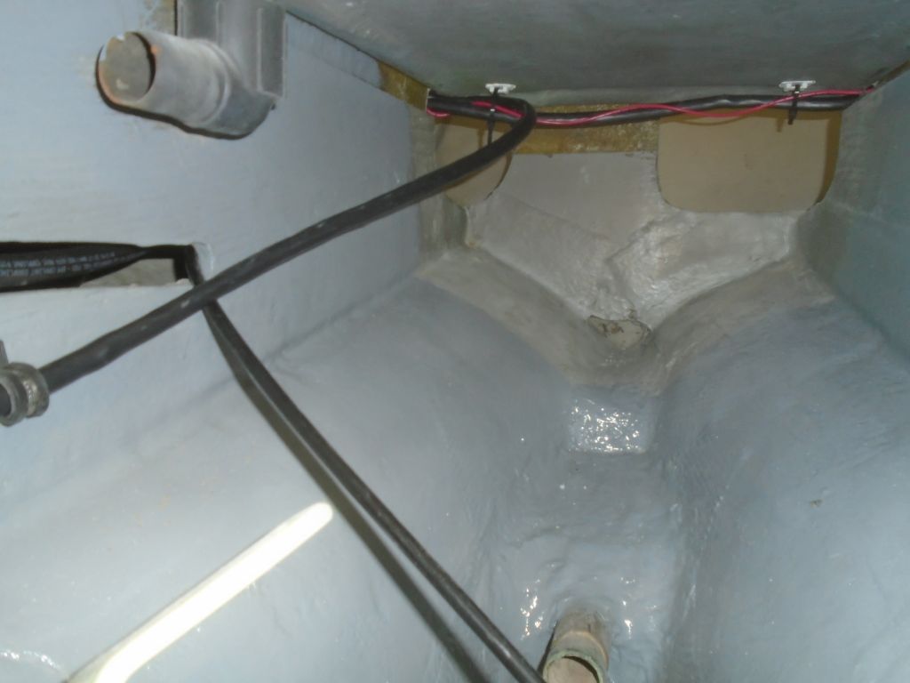
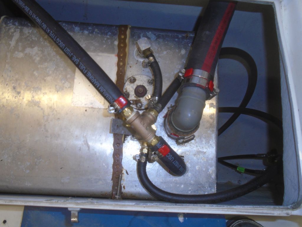
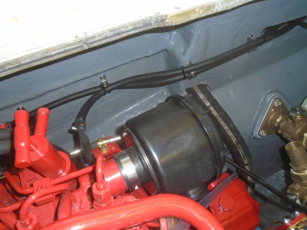
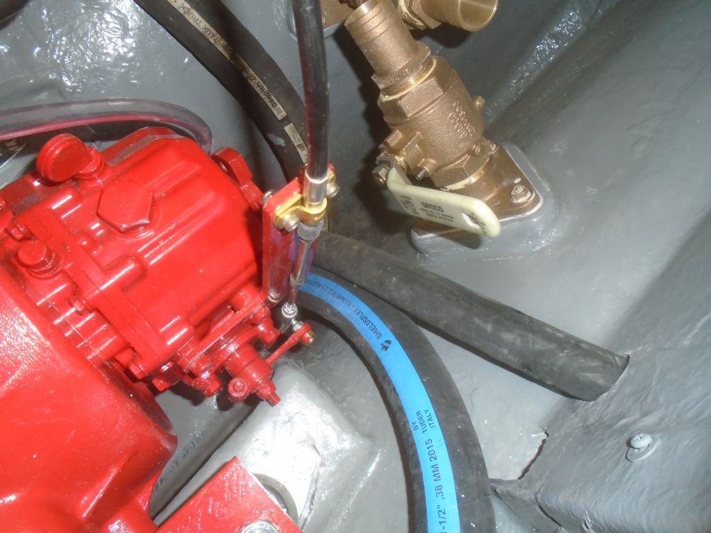
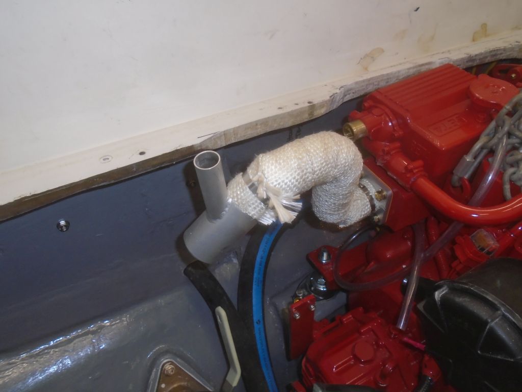
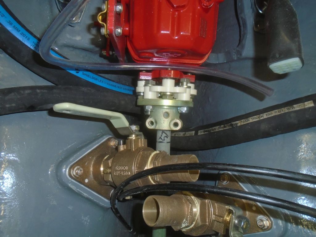
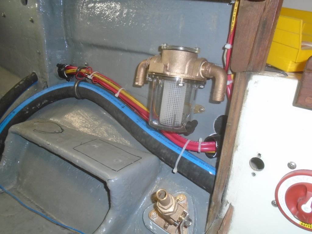
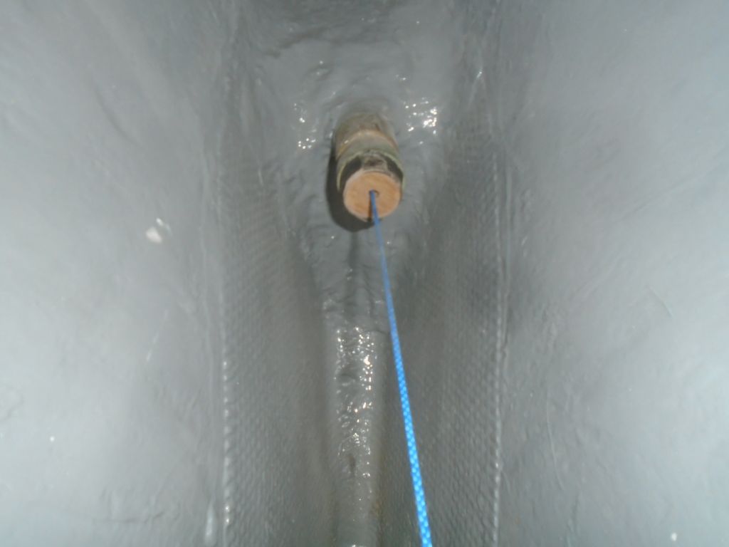
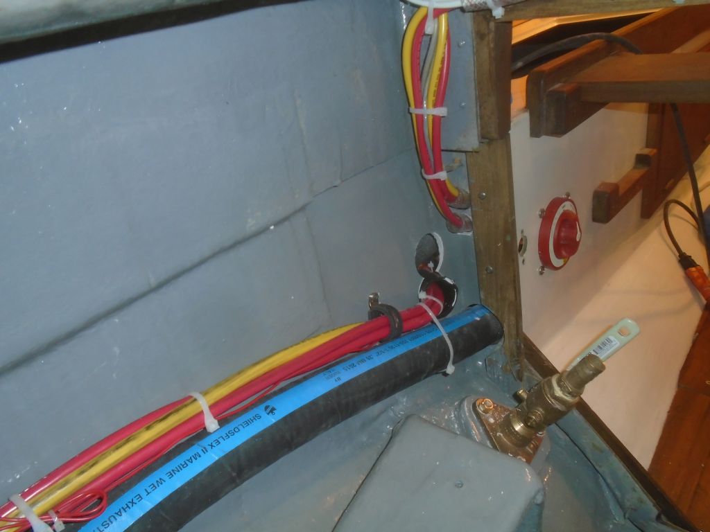
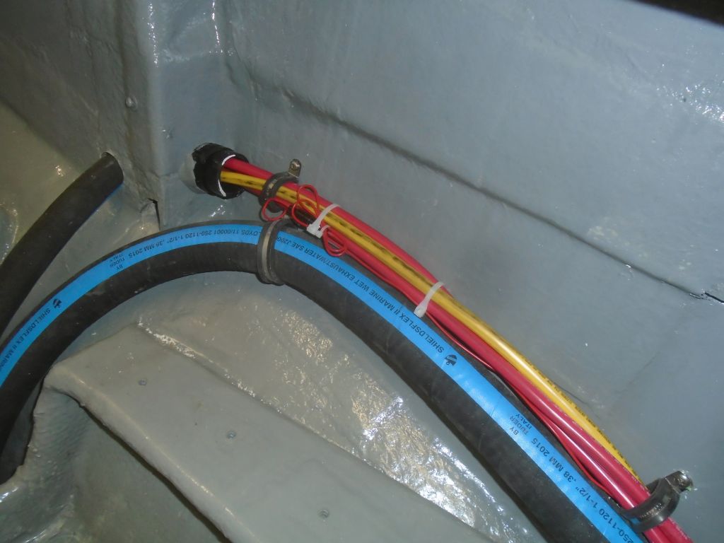
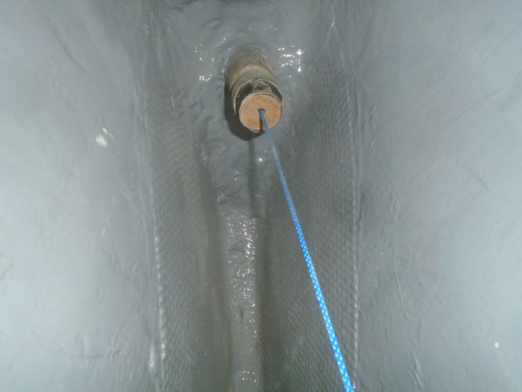
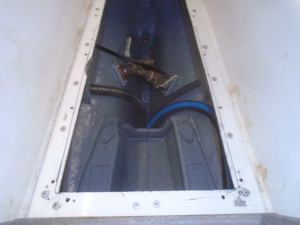
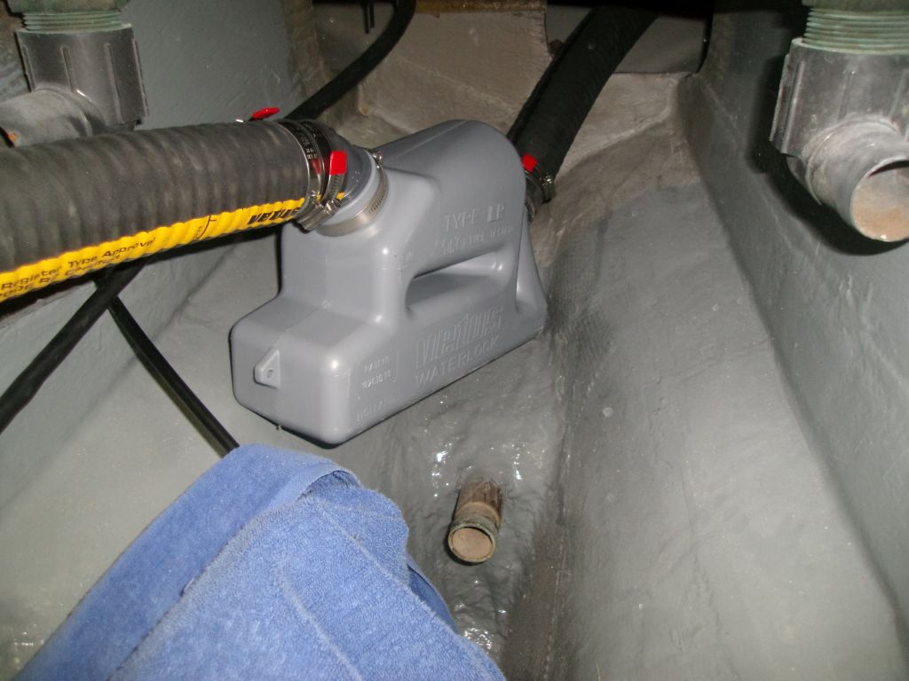
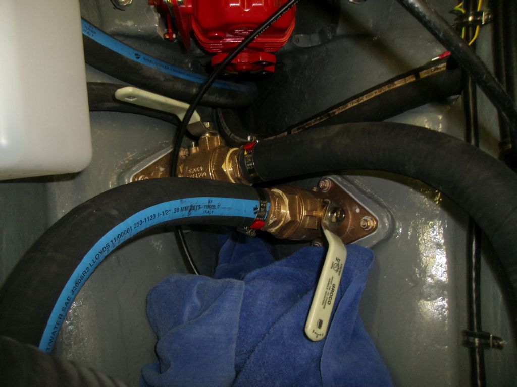
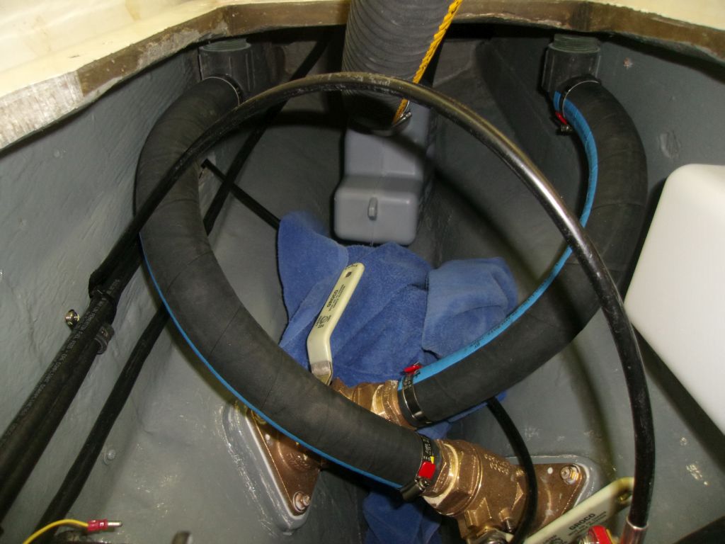
Although I awaited a replacement standard exhaust elbow for the engine, I could move forward with other portions of the exhaust system, namely the final length of hose and the waterlift muffler. With a length of hose pre-attached to the outlet side of the muffler, I could connect the other end of the hose to the gooseneck fitting inside the transom. With difficult access, a poorly-installed gooseneck that forced the hose nipple too close to the hull, and a slightly oversized barb on the connector, getting the new hose on was extremely difficult, but eventually I succeeded.
Leaving an extra length of hose for eventual connection to the engine elbow once it arrived, I made up the other end of the muffler as well, and would finish up the final installation as soon as the new part arrived.
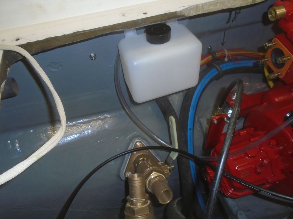
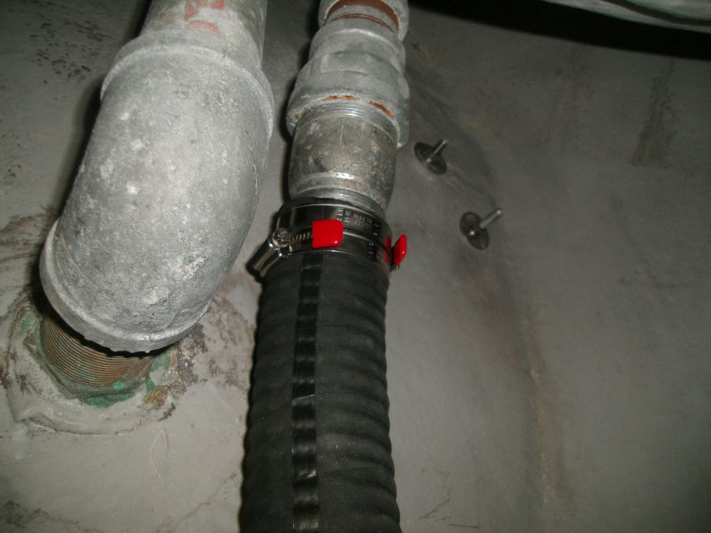
Meanwhile, I decided there was nothing to be gained by leaving the scupper hoses off any longer, so I cut the lengths as required and installed the new hoses.
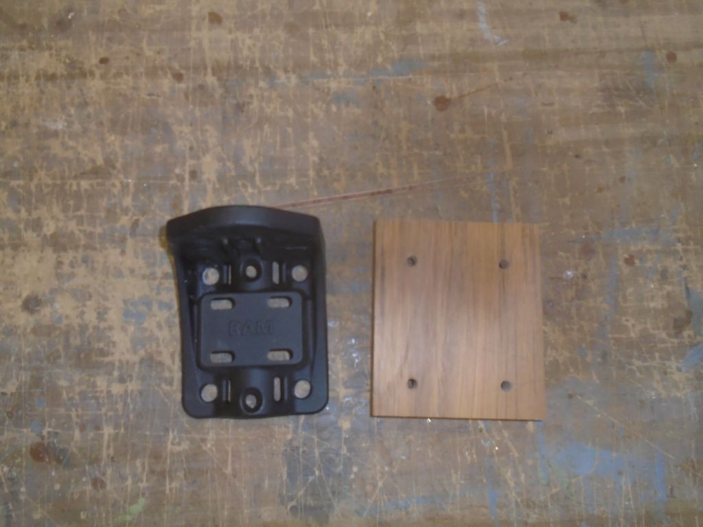
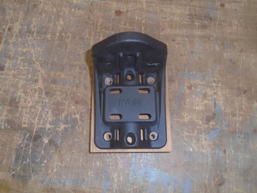
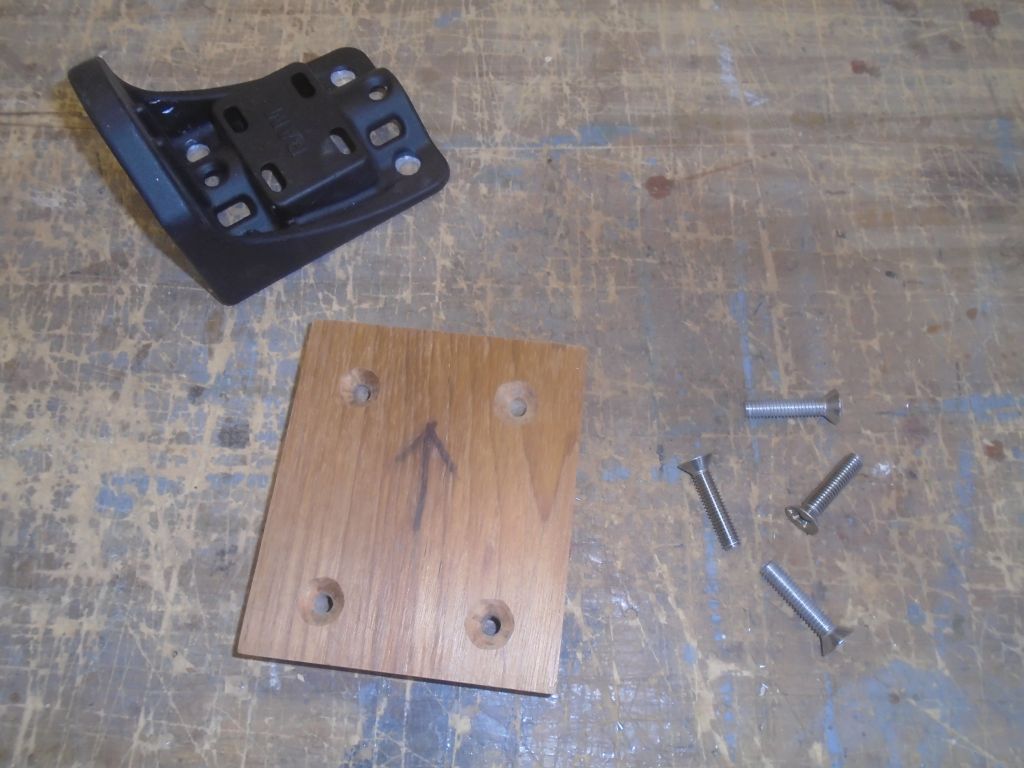
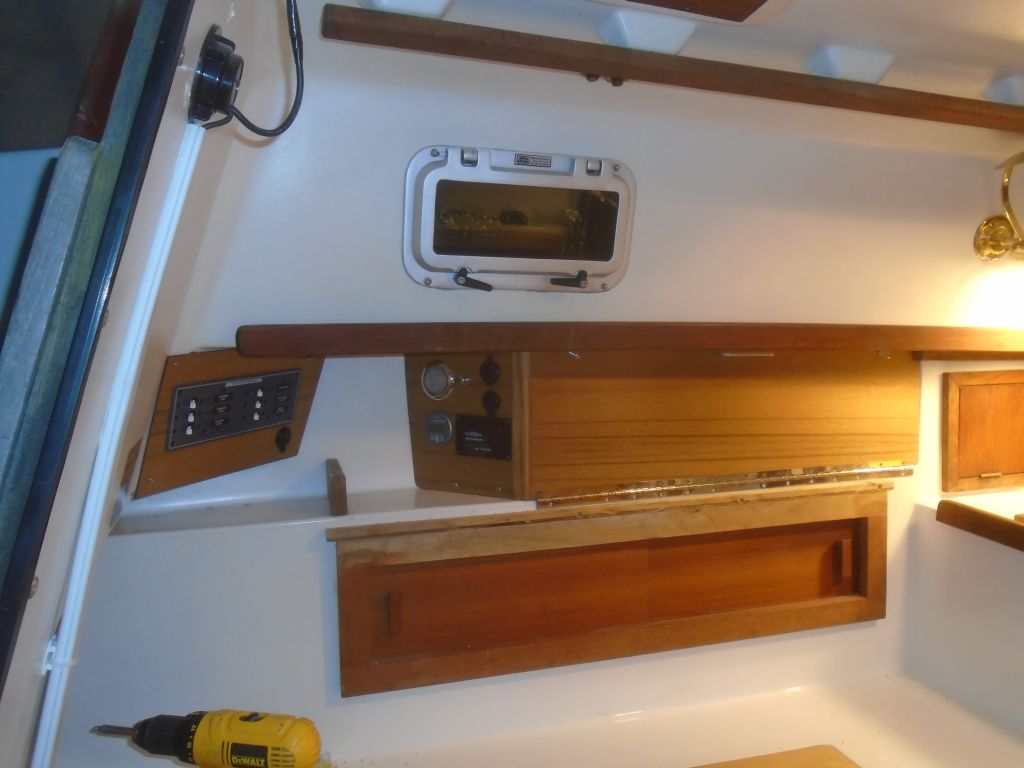
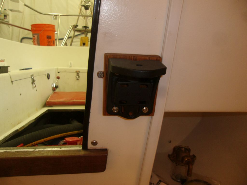
In the cabin, I oil-finished the teak mounting block for the RAM electronics mount, and, later, installed the mount base on the studs.


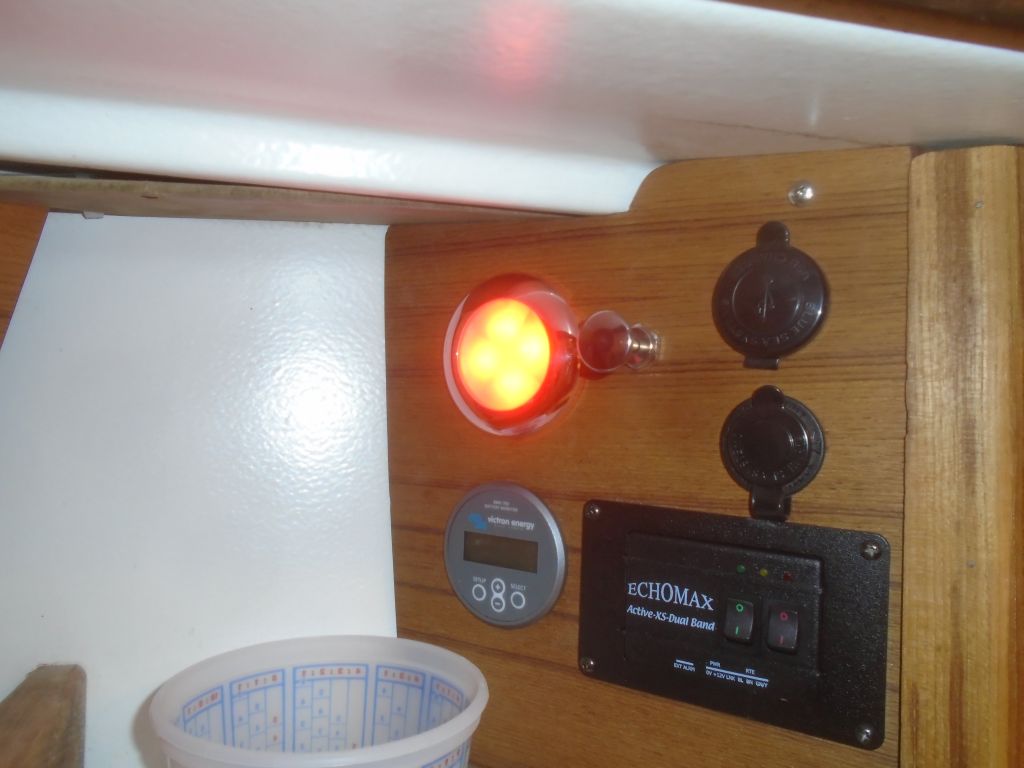
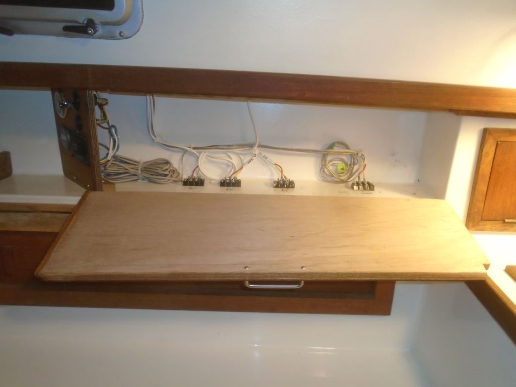
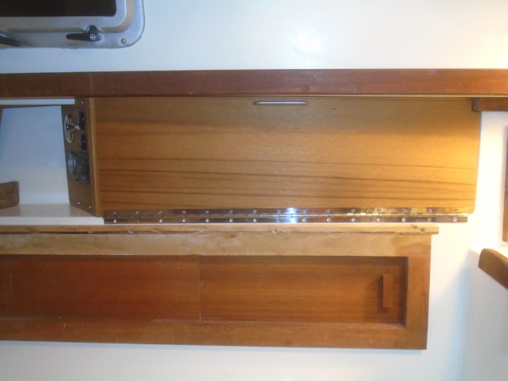
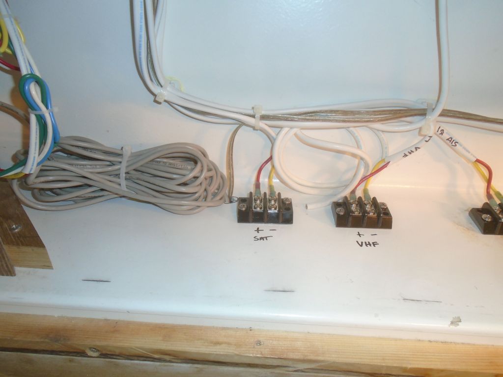
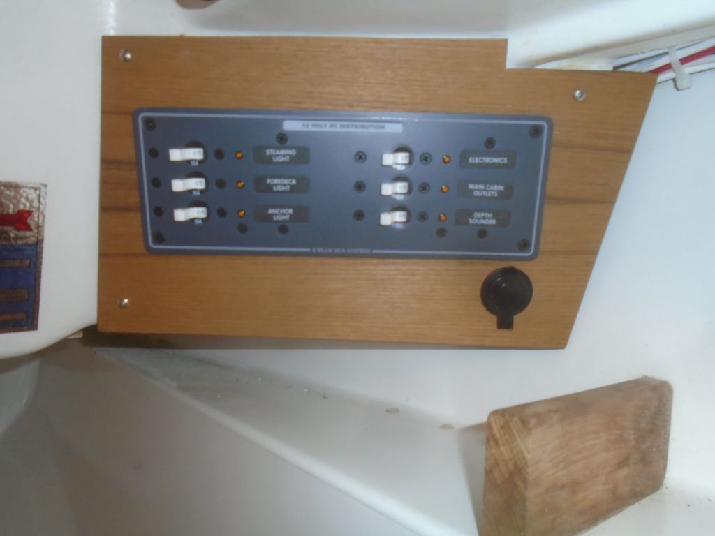
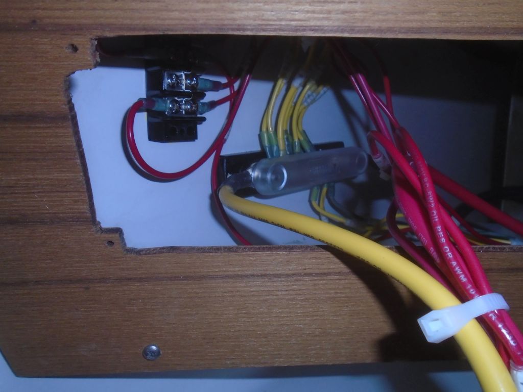
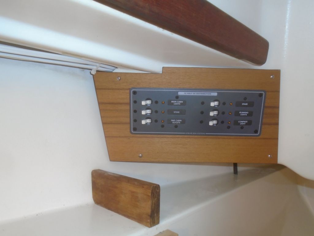
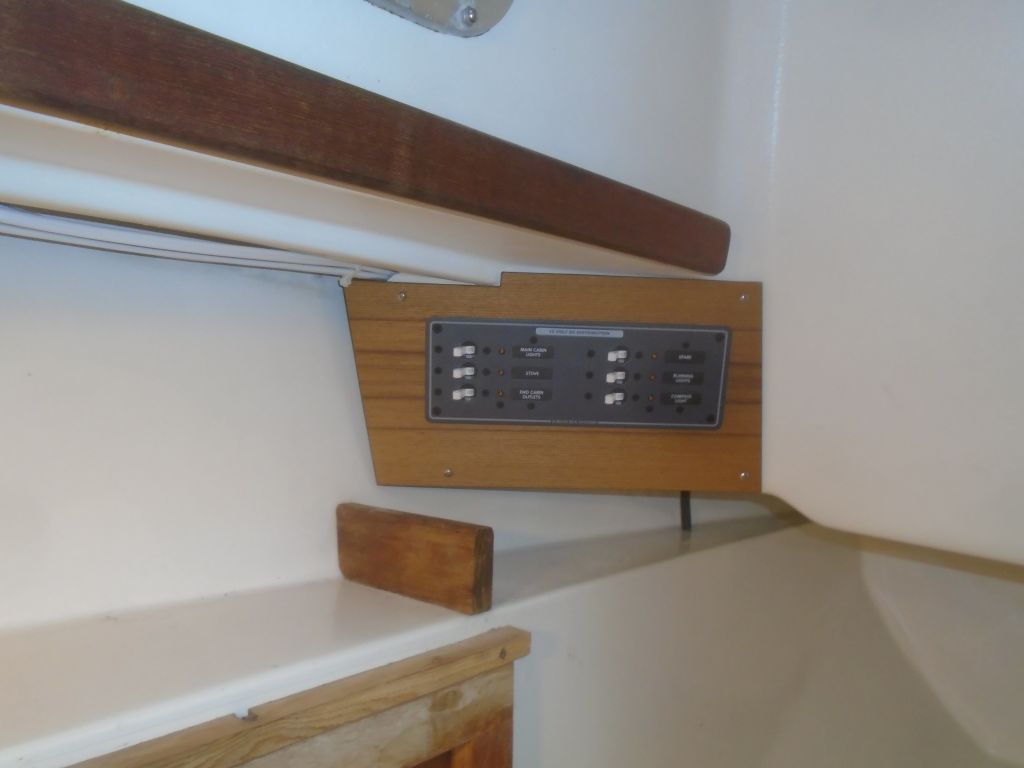
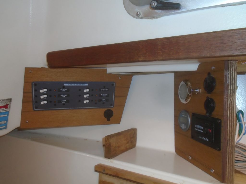
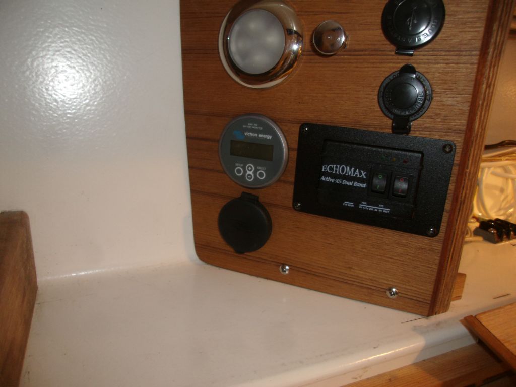
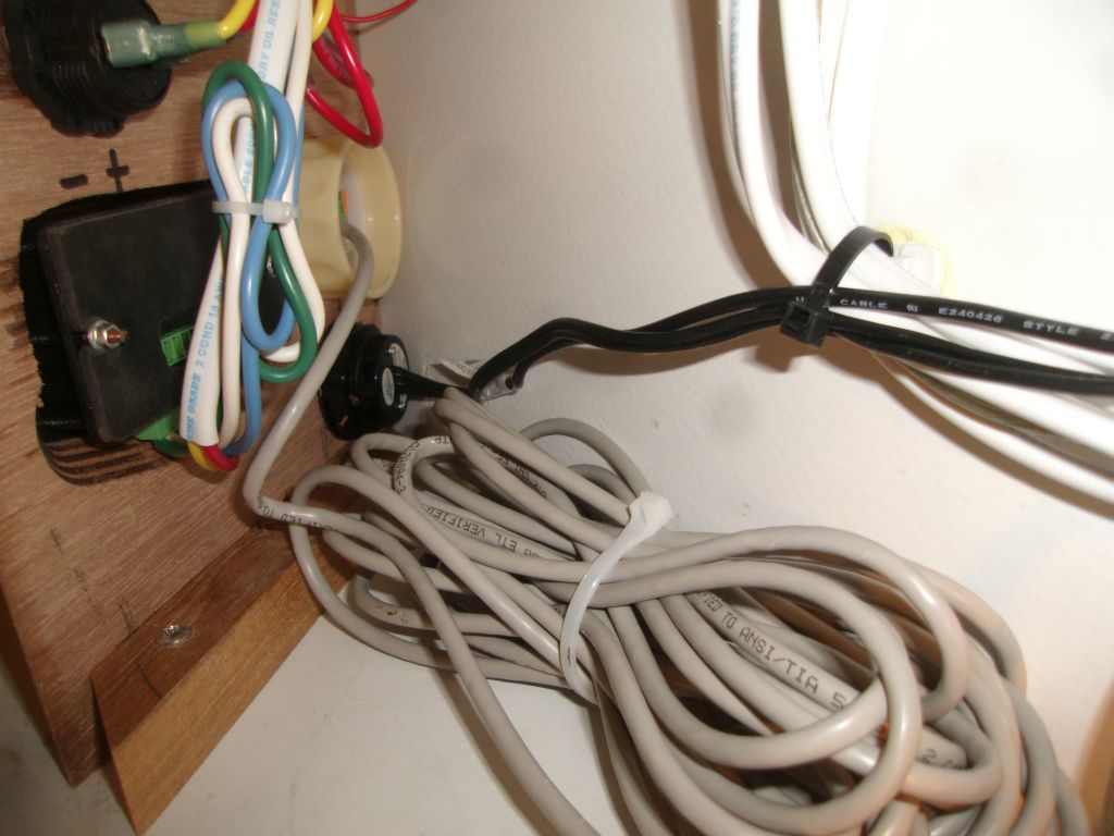
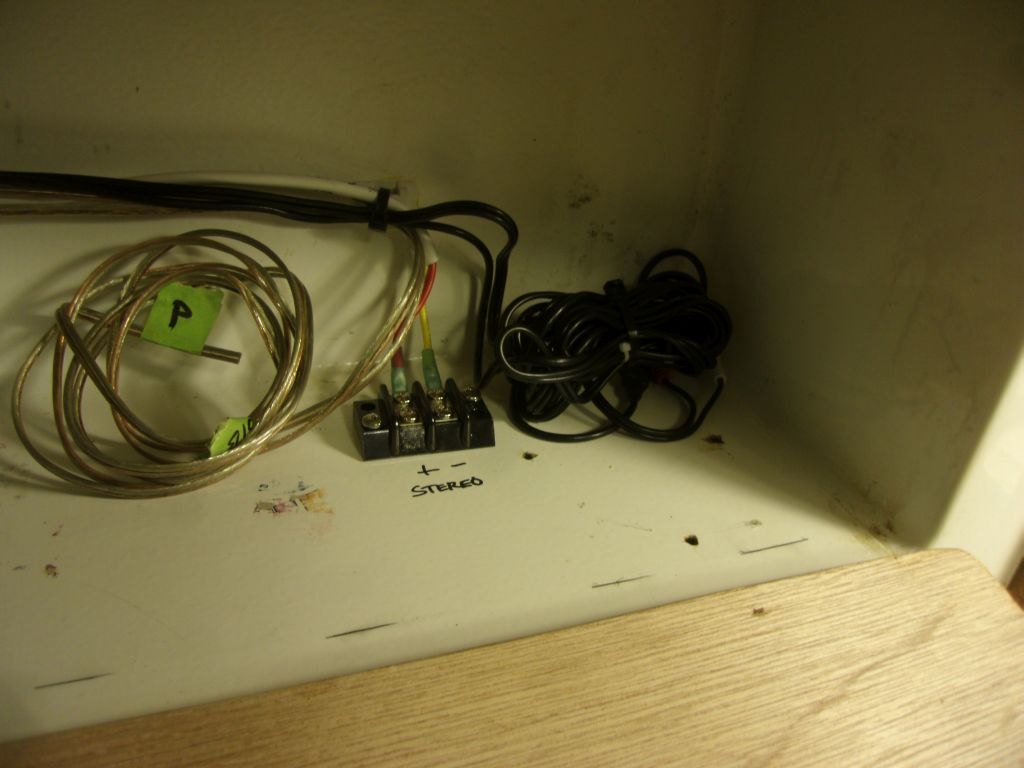
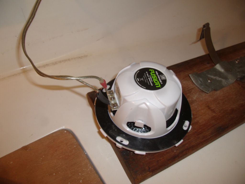
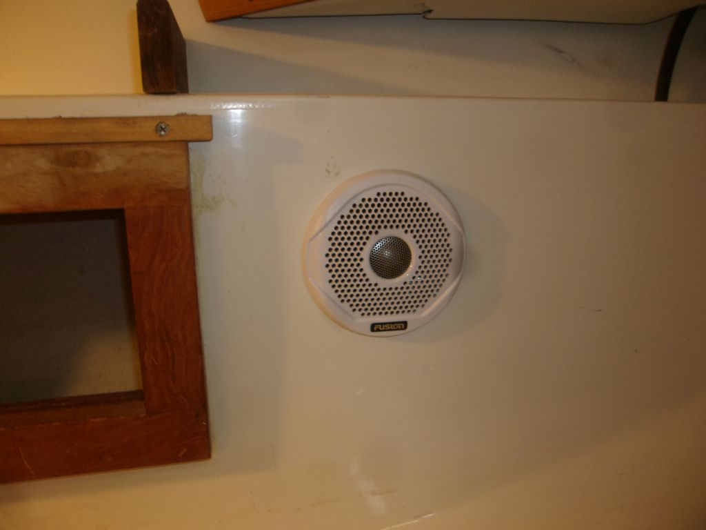
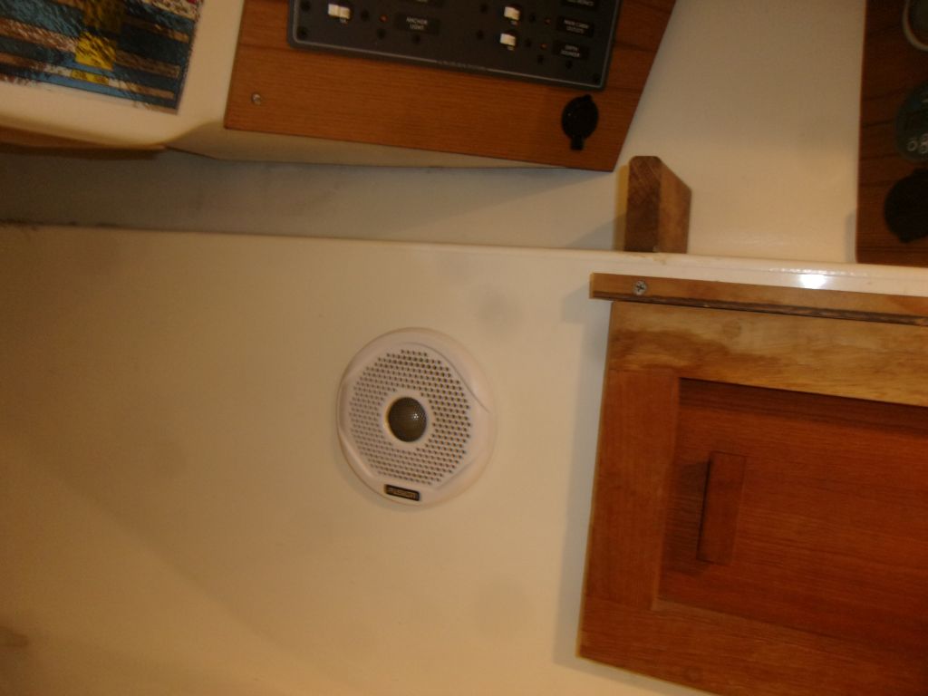
The owner had ordered a stereo and speakers, which arrived now, and I went ahead and installed the speakers in the chosen location, just aft of the settee back locker on each side where I’d previously run speaker wire. The stereo also came with a remote USB plug and headphone jack, which I installed in the angled electronics panel, leading the cables forward to where the stereo would hook up. I decided to wait on installing the stereo control unit in the panel till the VHF radio arrived later in the week, so I could make both installations at one time.
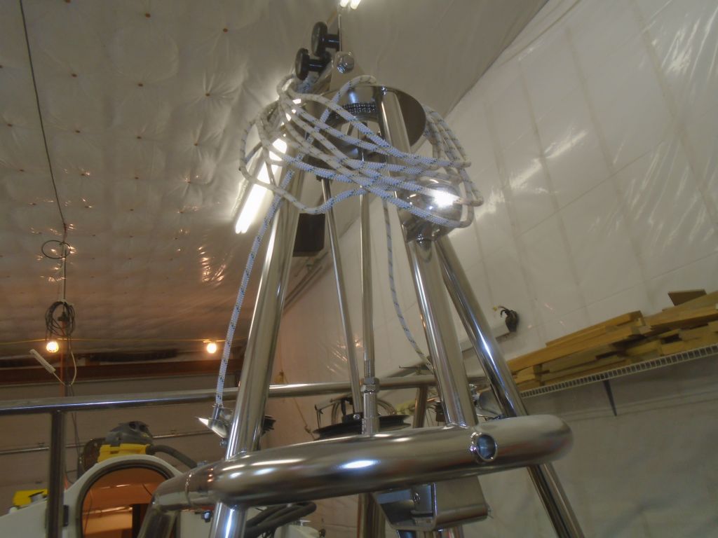
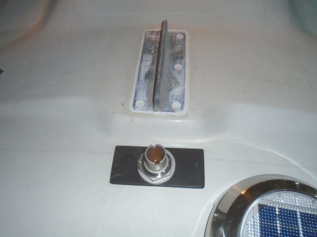
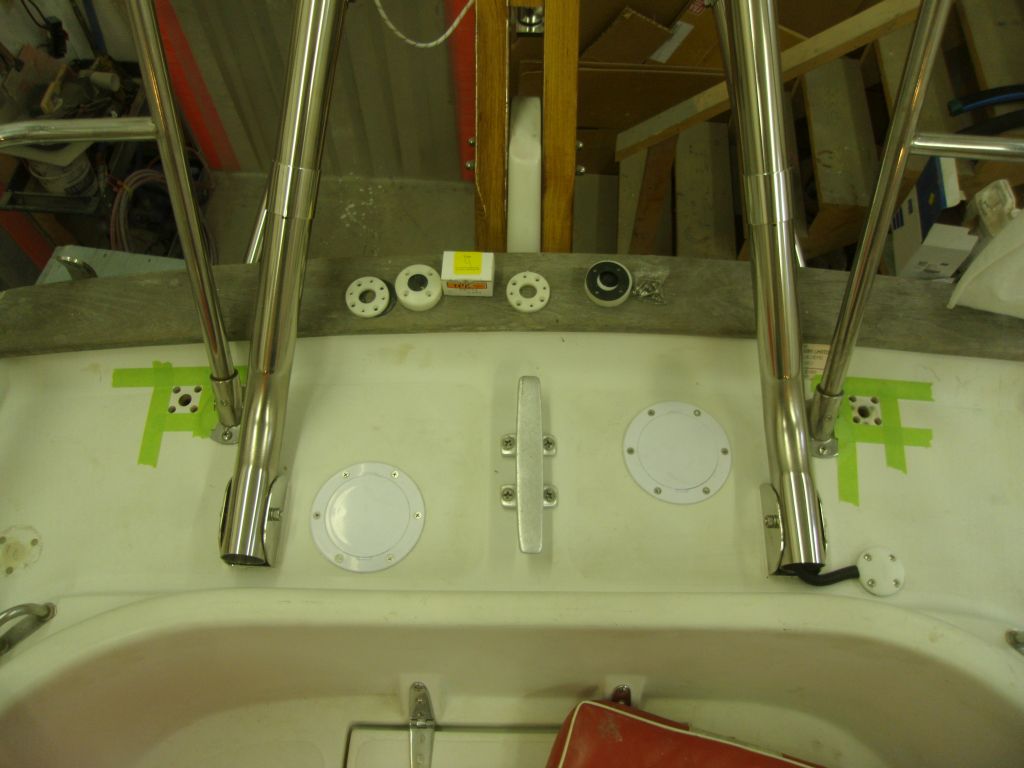
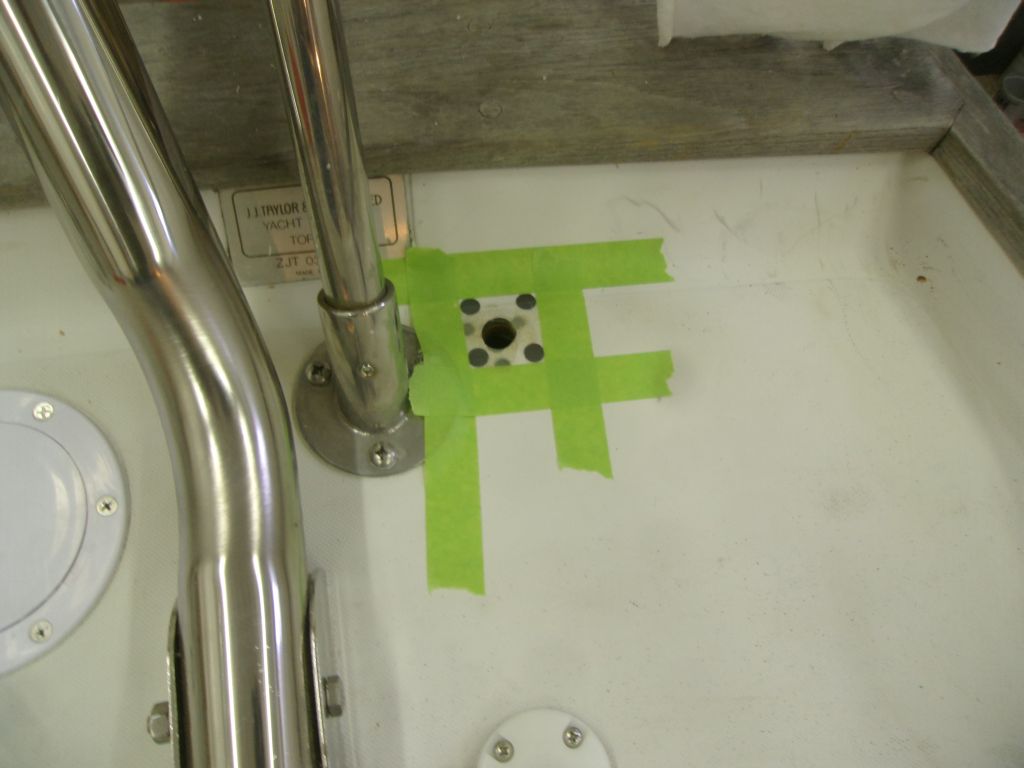
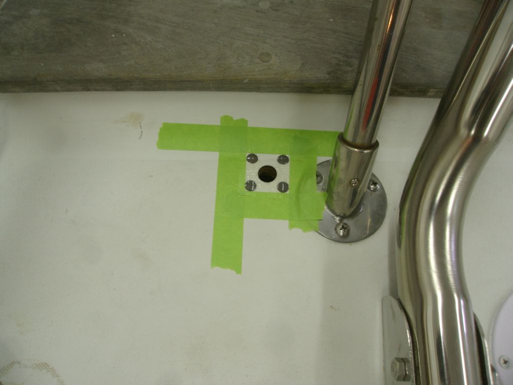
Preparing ahead for the eventual installation, at some later date, of an antenna or two at the stern, I prepared openings for two cable clams to run the wires and their connectors through the deck. In the usual way, I prepared the fastener locations by removing core material with a larger bit and filling the void with epoxy, leaving this to cure overnight.
Total time billed on this job today: 7 hours
0600 Weather Observation:
32°, cloudy. Forecast for the day: clouds, occasional shower, high in the 40s